a knowledge-based system for automated assembly planning
TRANSCRIPT
A Knowledge-Based System for Automated Assembly Planning
H. K.TOnshoff ( l ) , E. Menzel, H. S. Park Received on January 15,1992
This paper presents a computer-aided planning system for automated assembly cells, which uses the product description to generate assembly sequences and finally robot prognmms. For solving the entailed problems knowledge-based techniques are applied. In order to determine the assembly sequence, the assembly task has to be described by the jointing positions between the individual pans and by the assembly technology to be applied. The multitude of combinational possibilities for the various connections can be reduced with the help of planning rules. Within the layout planning, the travel route is optimised LO achieve the minimum cycle time. On the functional level of automatic programming, the assembly processes are described in terms of their operational functions. On the language level, the individual functions are then aanslated into commands for the specific machines.
Keywords : knowledge based systems, assembly sequence, layout planning. programming of robots
1 Introduction
Until now automation in the field of assembly has only been achieved for concrete. narrowly-defined assembly tasks. In the future. though, only flexible assembly systems will be economic, the reasons being the increasing range of variants in conjunction with decreasing batch sizes as well as the increasingly shorter product lifecycles and delivery times 11-3/. This has become clear in the last few years, considering the substantial increase of the use of industrial robots for assembly tasks.
Due to the often extensive, highly complex peripheral equipment required, the planning and consrdction of flexible assembly systems is usually not computer- aided and is often based on the experience and know-how of assembly planners. For automating planning tasks, though, suitable software is becoming more and more necessary in order to allow rapid. comprehensive completion of the planning phase.
This paper concentrates on the development of a computer-aided planning system for robot-based assembly cells. Geomemcal information on the objecrs to be assembled as well as technological knowledge about assembly is included in the system. The central problem is the determination of the assembly sequence. This sequence is the basis for the subsequent complete planning of the layout of the assembly cell as well as the generation of the robot program.
2 Knowledge-based Generation of Assemhly Sequences
Until now the assembly sequences have been determined by using precursor and successor lists /4/ as well as disassembly graphs /5,6/. Here we present an expert system for determining the optimum assembly sequence for assembly tasks with few components. Currently, the system uses data from technical drawings. which is entered interactively, but an interface to a CAD is planned for the future.
2.1
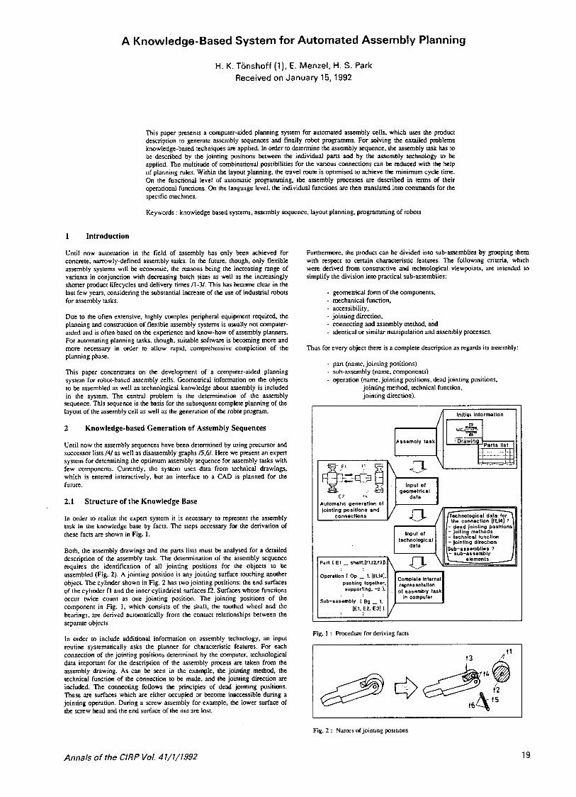
In order to realize the expen system it is necessary to represent the assembly task in the knowledge base by facts. The steps necessary for the derivation of these facts are shown in Fig. 1.
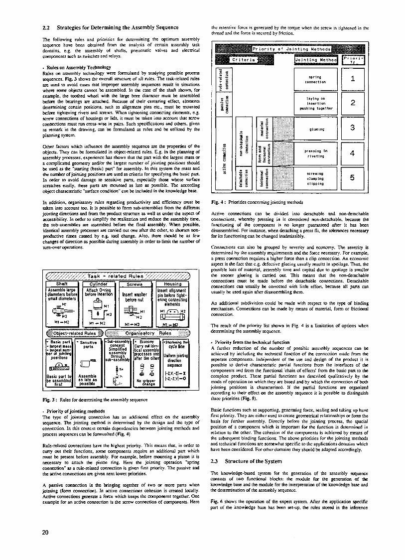
Both, the assembly drawings and the p m s lists must be analysed for a detailed description of the assembly task. The determination of the assembly sequence requires the identification of all jointing positions for the objects to be assembled (Fig. 2). A jointing position is any jointing surface touching another object. The cylinder shown in Fig. 2 has two jointing positions: the end surfaces of the cylinder f l and the inner cylindrical surfaces E. Surfaces whose functions occur twice count as one jointing position. The jointing positions of the component in Fig. I. which consists of the shaft. the toothed wheel and the bearings, are derived automatically from the contilct relationships between the sepwdre objects.
In order to include additional information on assembly technology, an input routine systematically asks the planner for chwacteristic features. For each connection of the jointing positions determined by the computer, technological data important for the description of the assembly process are taken from the assembly drawing. As can be seen in the example, the jointing method, the technical function of the connection to be made. and the jointing direction are included. The connecting follows the principles of dead jointing positions. These are surfuces which are either occupied or become inaccessible during a jointing operation. During a screw assembly for example, the lower surface of the xrew head and the end surface of the nut are lost.
Structure of the Knowledge Base
Furthermore, the product can be divided into sub-assemblies by grouping them with respect to certain characteristic features. The following criteria, which were derived from consmctive and technological viewpoints, are intended to simplify the division into practical sub-assemblies:
- geometrical form of the components, ~ mechanical function, ~ accessibility, - jointing direction, - connecting and assembly method, and ~ identical or similar manipulation and assembly processes.
Thus for every object there is a complete description as regards its assembly:
- part (name, jointing positions) ~ sub-assembly (name, components) - operation (name, jointing positions. dead jointing positions.
jointing method, technical function, jointing direction).
A Initial intormation I /I I
technical function jointing direction
ub-assemblies 7
I
Fig. 1 : Procedure for deriving facts
L I
Fig. f : Names of jointing positions
Annals of the ClRP Vol. 41/1/1992 19
2.2 Strategies for Determining the Assembly Sequence
The following rules and priorities for determining the optimum assembly sequence have been obtained from the analysis of certain assembly task domains, e.g. the assembly of shafts, pneumatic valves and elecmcal components such as switches and relays.
- Rules on Assembly Technology Rules on assembly technology were formulated by studying possible process sequences. Fig. 3 shows the overall swcture of all rules. l3e task-related rules are used to avoid cases that improper assembly sequences result in situations where some objects cannot be assembled. In the case of the shaft shown, for example, the toothed wheel with the large bore diameter must be assembled before the bearings are attached. Because of their centering effect, elements determining certain positions, such as alignment pins etc., must be mounted before tightening rivets and screws. When tightening connecting elements, e.g. screw connections of housings or lids, it must be taken into account that screw connections must run cross-wise in pairs. Such specifications and others, given as remark in the drawing, can be formulated as rules and be utilized by the planning system.
Other factors which influence the assembly sequence are the pmperdes of the objects. They can be formulated in object-related rules. E.g. in the planning of assembly processes. experience has shown that the part with the largest mass or a complicated geomeuy and/or the largest number of jointing positions should be used as the "starting (basic) part" for assembly. In this sysrem the mass and the number of jointing positions are used as criteria for specifying the basic part. In order to avoid damage to sensitive parts, especially those whose surface scratches easily, these parts are mounted as late as possible. The according object characteristic "surface condition" can be included in the knowledge base.
In addition. organisatory rules regarding productivity and efficiency must be taken into account too. It is possible to form sub-assemblies from the different jointing directions and from the product suucture as well as under the aspect of accessibility. In order to simplify the realization and reduce the assembly time. the sub-assemblies are assembled before the final assembly. When possible. idtntical assembly processes are carried out one after the other. to shorten non- productive times caused by e.g. tool change. Also. there should be as few changes of direction as possible during assembly in order to limit the number of turn-over operations
Fig. 3 : Rules for determining the assembly sequence
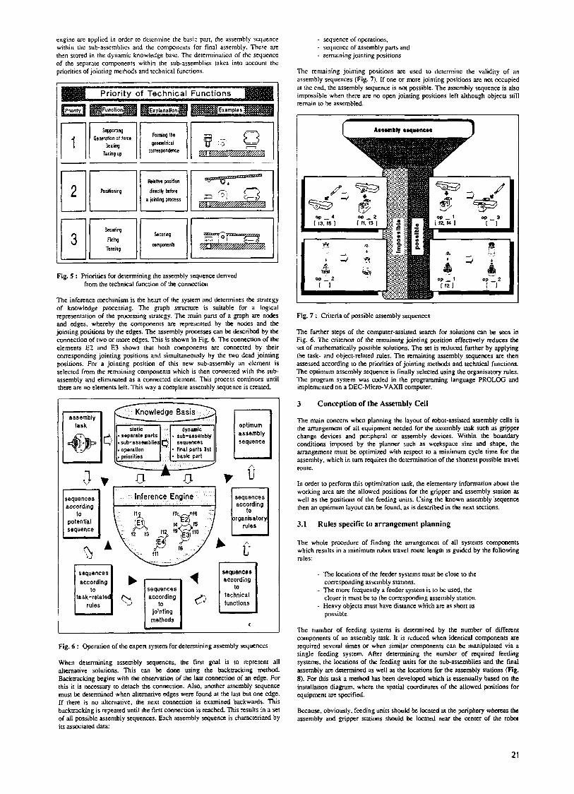
- Priority of jointing methods The type of jointing connection has an additional effect on the assembly sequence. The jointing method is determined by the design and the type of connection. In this context cenain dependencies between jointing methods and process sequences can be formualted (Fig. 4).
Rule-related connections have the highest priority. This means that. in order to carry out their functions, some components require an additional part which must be present before assembly. For example, before mounting a piston it is necessary to attach the piston ring. Hen the jointing operation "spring connection" as a rule-related connection is given first priority. The passive and the active connections are given next lower priorities.
A passive connection is the bringing together of two or more pans when jointing (form connection). In active connections cohesion is created locally. Active connections generate a force which keeps the components together. One example for an active connection is the screw connection of components. Here
the retentive force is generated by the torque when the screw is tightened in th thread and the force is secured by friction.
apring connect I on - laying on inaertion
puahlng together
E l F l
Fig. 4 : Priorities concerning jointing methods
Active connections can be divided into detachable and non-detachable connections, whereby pressing in is considered non-detachable, because the functioning of the component is no longer guardnteed after it has been disassemblied. For instance. when detaching a press fi t . the tolerances necessary for its functioning can be changed inadmissibly.
Connections can also be grouped by severity and economy. The severity is determined by the assembly requirements and the force necessary. For example, a press connection requires a higher force than a clip connection. An economic aspect is the fact that e.g. defective glueing usually results in spoilage. Thus, the possible loss of material, assembly time and capital due to spoilage is smaller the sooner glueing is carried out. This means that the non-detachable connections must be made before the detachable connections. Detachable connections can usually be corrected with little effort, because all parts can usually be used again after disassembling them.
An additional subdivision could be mrde with respect to the type of binding mechanism. Connections can be made by means of material, form or frictional connection.
The result of the priority list shown in Fig. 4 is a limitation of options when determining the assembly sequence.
- Priority from the technical function A further reduction of the number of possible assembly sequences can be achieved by including the technical function of the connection made from the seperate components. Independent of the use and design of the product it is possible to derive characteristic panial functions from the interfaces of the components and from the functional 'chain of effects' from the basic part to the complete product. These partial functions are described qualitatively by the mode of operation on which they are based and by which the connection of both jointing positions is characterized. If the partial functions are organized according to their effect on the assembly sequence it is possible to distinguish three priorities (Fig. 5).
Basic functions such as suppomng, generating force. sealing and taking up have first priority. They are either used to create geomemcal relationships or form the basis for funher assembly. Directly before the jointing pmess, the spacial position of a component which is imponint for the function is determined i n relation to the other. The cohesion of the components is achieved by means of the subsequent binding functions. The above priorities for the jointing methods and technical functions are somewhrt specific to the applications domains which have been considered. For other domains they should be adapted accordingly.
2.3 Structure of the System
The knowledge-based system for the generation of the assembly sequence consists of two functional blocks: the module for the generation of the knowledge base and the module for the interpiztation of the knowledge base and the determination of the assembly sequence.
Fig. 6 shows the operation of the expert system. After the application specific pan of the knowledge base has been set-up, the rules stored in the inference
20
engine arc applied in order to determine the basic part, the assembly sequence within the sub-assemblies and the components for final assembly. These are thcn stored in the dynamic knowledge bnse. The determination of the sequence of the separate components within the sub-assemblies takes into account the priorities of jointing nwhods and technical functions.
Fig. 5 : Priorities for determining the assembly sequence derived from the technical function of the connection
The inference mechanism is the hem of the system and determines the strategy of knowledge processing. The graph smcture is suitable for a logical represenration of the processing strategy. The main pans of a graph are nodes and edges, whereby the components are represented by the nodes and the jointing positions by the edges. The assembly processes can be described by the connection of two or more edges. This is shown in Fig. 6. The connection of the elements E? and €3 shows that both components are connected by their corresponding jointing positions and simultaneously by the two dead jointing positions. For a jointing position of this new sub-assembly an element is selected from the remaining conipnents which is then connected with the sub- assembly and eliminated as a connected element. This process continues until there are no elements left. This way a complete assembly sequence is created.
sequences
jointing
sequences according
technical U functions
m C
Fig. 6 : Operation of the expert system for determining assembly sequences
When determining assembly sequences. the first goal is to represent all alternative solutions. This can be done using the backtracking method. Backtracking begins with the observation of the last connection of an edge. For this it is necessary to detach the connection. Also, mother assembly sequence must be determined when alternative edges were found at the last but one edge. If there is no alternative, the next connection is examined backwards. This backtracking is repeated until the first connection is reached. This results in a set of ail possible assembly sequences. Each assembly sequence is Characterized by its associated data:
- sequence of operations, - sequence of assembly pans and ~ remaining jointing positions.
The remaining jointing positions are used to determine the validity of an assembly sequences (Fig. 7). If one or more jointing positions are not occupied at the end, the assembly sequence is not possible. The assembly sequence is also impossible when there are no open jointing positions left although objects still remain to be assembled.
Aaaembly roquencea i 1
I
Fig. 7 : Criteria of possible assembly sequences
The further steps of the computer-assisted search for solutions can be seen in Fig. 6. The criterion of the remaining jointing position effectively reduces the set of mathematically possible solutions. The set is reduced further by applying the task- and object-related rules. The remaining assembly sequences are then assessed according to the priorities of jointing methods and technical functions. The optimum assembly sequence is finally selected using the organisatory rules. The program system was coded in the programming language PROLOG and implemented on a DEC-Micro-VAXn computer.
3
The main concern when planning the layout of robot-assisted assembly cells is the arrangement of all equipment needed for the assembly task such as gripper change devices and peripheral or assembly devices. Within the boundary conditions imposed by the planner such as workspace size and shape. the arrangement must be optimized with respect to a minimum cycle time for the assembly, which in turn requires the determination of the shortest possible travel route.
In order to perform this optimization task, the elementary information about the working area are the allowed positions for the gripper and assembly station as well as the positions of the feeding units. Using the known assembly.sequence then an optimum layout can be found. as is described in the next sections.
3.1
Conception of the Assembly Cell
Rules specific to arrangement planning
The whole procedure of finding the arrangement of all systems components which resulrs in a minimum robot travel route length is guided by the following rules:
- The locations of the feeder systems must be close to the corresponding assembly stations.
- The more frequently a feeder systeni is to be used, the closer it must be to the corresponding assembly station.
~ Heavy objects must have distance which are as short as possible.
The number of feeding systems is determined by the number of different components of an assembly task. It is reduced when identical components are. required several times or when similar components can be manipulated via a single feeding system. After determining the number of required feeding systems, the locations of the feeding units for the sub-assemblies and the final assembly are determined as well as the locations for the assembly stations (Fig. 8). For this task a method has been developed which is essentially based on the installation diagKdm. where the spatial coordinates of the allowed positions for equipment are specified.
Because, obviously, feeding units should be located at the periphery whereas the assembly and egipper stations should be located near the center of the robot
21
working area, in the shown example there u e basically 5!x3!=720 possible arrangements for the different stations.
[ Subdivision of Locations 1
A. B : Locations 01 leeder systems for sub-assembly
feeder systems for final assembly
C. D. E : Locatbns of
Legend: SS : Sub-assembly station FS : Final assembly station
Fig. 8 : Rule for arrangement of locations
In the example the outer locations of the feeder systems (A.B) or (DE) are always allocated to the sub-assembly station and the other locations to the find assembly station. Although the locations (B,C) or (C,D) are. even closer to the subassembly station, this would not result in a minimum total navel length, because it would be necessary to access the location A or E from the final assembly station, but these are furthest away. The selection of the locations (A,B) or @E) for the sub-assembly station means that no excessively long travel routes occurr, and the number of possible solutions for the optimum arrangment is reduced to 3!x2!~3!=72. A further reduction can be the result of boundary conditions requiring a fixed position for a Certain station. Boundary conditions include factors such as collision avoidance or interfaces to subsequent stations. Fixed positions within the assembly cell can be required by high precision assembly operations, which the robot only fullfils in a certain area of the workspace.
For these arrangements now the overall travel path of the robot is calculated using the methods explained in section 3.2.. which effectively incorporate the second rule and furthermore use the number of objects to be assembled. the starting position of a sub-assembly task and the individual travel path. From all arrangements, then that one is selected which minimizes the overall travel path length.
In case there is more thari one arrangement where the minimum travel length is achieved, the third rule is applied. Experiments have shown that the total travel time for an assembly task is not essentially affected by a weight-dependent positioning of the objects in the working area. In manual assembly, though. this poht is an important physiological aspect. In automated assembly, too, the distances over which heavy objects are moved should be as short as possible in order to avoid unnecessary strain on the robot and to reduce wear and tear on moving parts. For this reawn this rule is used as an assessment criterion for the selection of the optimum travel route when the program has found several equivalent solutions.
3.2
The robot assembly route is essentially determined by the assembly sequence. This route, which the robot must travel in order to perform the assembly, is independent of the arrangement of the equipment, and can be determined from the asscmbly sequence and the gripper CharaCteriStiCS. The moment for gripper change is hereby entered into the assembly sequence. On the basis of the determined robot assembly route. all alternative travel routes are. represented by the combinatory possibilities of allocating the equipment.
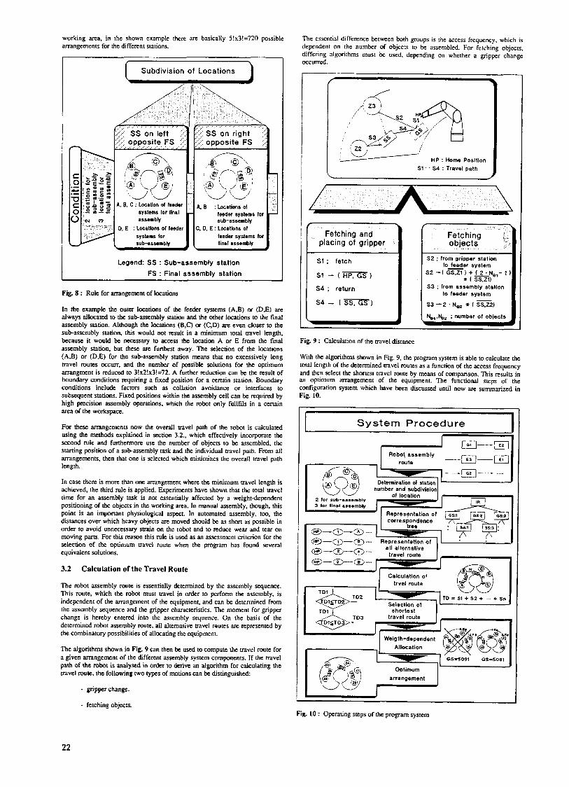
The algorithms shown in Fig. 9 can then be used to compute the travel route for a given arrangement of the different assembly system components. If the travel path of the robot is analysed in order 10 derive illl algorithm for calculating the navel route, the following two types of motions can be distinguished:
Calculation of the Travel Route
- gripper change.
- fetching objects.
The essential difference between both groups is the access frequency, which is dependent on the number of objects to be assembled. For fetching objects. differing algorithms must be used. depending on whether a gripper change occurred.
S1. ' S4 Travel path
Fetching and placing of gripper
~-
Sl ; fetch
s1- (m)
$4 - 1sST.T) S4 ; return
Fetching and placing of gripper
s1- (m)
$4 - 1sST.T) S4 ; return
Fig. 9 : Cdculation of the navel distance
5 3 ; from assembly station to feeder system
53 -2 .N- i t ISS.22)
With the algorithms shown in Fig. 9. the program system is able to calculate the total length of the determined travel routes as a function of the access frequency and then select the shortest navel route by means of comparison. This results in an optimum arrangement of the equipment. The functional steps of the configuration system which have been discussed until now are summarized in Fig. 10.
System Procedure
I I
1-
Fig. 10 : Operating steps of the program system
22
Due to its suictly object-oriented stnicture, the p r o g m system can be used flexibly. For instance. the number of ststions cdn be expanded by screwing or glueing stations.
4 Automatic Generation of the Robot Programs
In order to generate a robot program, the planner must have knowledge about assembly processes and about the equipment involved as well as a detailed plant (cell) layout. As all this information is available in the computer because of the previous planning phases, the robot program can be generated automatically.
The required data for automatic programming are the assembly sequence, the amngement of the equipment and the syntax/semantics of the robot's programming language. The movement sequence is fmt put mto a functional level and then descnbed symbolically by using manipulation functions according to VDI rule 2860 17/. A description of this kind offers the following advantages and possibilities:
- Simple, straightforward representation of complex movement sequences lake into account all requirements specific to certain tasks
processes are easy to recognize and avoid
e.g. inclusion of the monitoring functions.
- Superfluous or impractical panid functions and
- Simple expansion by additional details.
In a further step, the manipulation functions are convened to the respective programming language. The programming language used in our example is AiML.
4.1 Model for the Description of Robot Movements
The separate phases of movement can be described by using the defined functions. The partial manipulation functions useful for the description are moving and securing. The function securing is used to describe the movement of grippers. Tensing and relaxing are used for the grippers which hold the objecu in a frictional connection by the mvement of jaws. Holding and detaching an of importance for describing the action of magnetic and vacuum grippers.
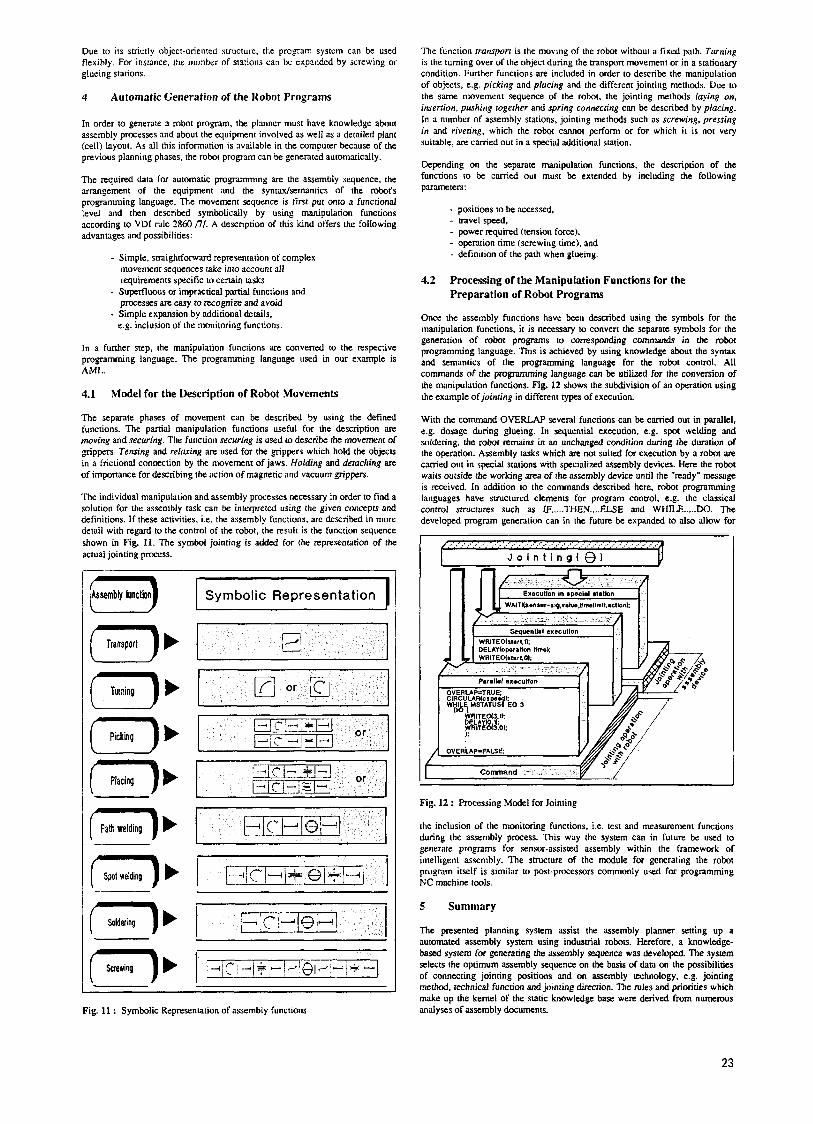
The individual manipulation and aswnbly processes necessary in order to find a solution for the assembly task can be interpreted using the given concepts and definitions. If these activities, i.e. the assembly functions, are described in more detail with regard to the control of the robot, the result is the function sequence shown in Fig. 11. The symbol jointing is added for the representation of the actual jointing process.
#Assembly function 3 1, Transporl
1' Pickinq
Symbolic Representation
r -7 ' Path welding
i' Spa1 welding
r b Soldering
(-)' I I
Fig. 11 : Symbolic Representation of assembly functions
The function transport is the moving of the robot without B fixed path. Turning is the turning over of the object during the uanspon movement or in a stationary condition. Further functions are included in order to describe the manipulation of objects, e.g. picking and plocing and the different jointing methods. Due to the same movement sequence of the robot. the jointing methods laying on. insertion, pushing together and spring connecring can be described by placing. In a number of assembly stations, jointing methods such as screwing, pressing in md rivermg, which the robot cannot perform or for which it is not very suitable. an carried out in a special additional station.
Depending on the separate manipulation functions, the description of the functions to be carried out must be extended by including the following parameters:
- positions to be accessed. - navel speed, - power required (tension force), - operation time (screwing time). and - definition of the path when glueing.
4.2 Processing of the iManipulation Functions for the Preparation of Robot Programs
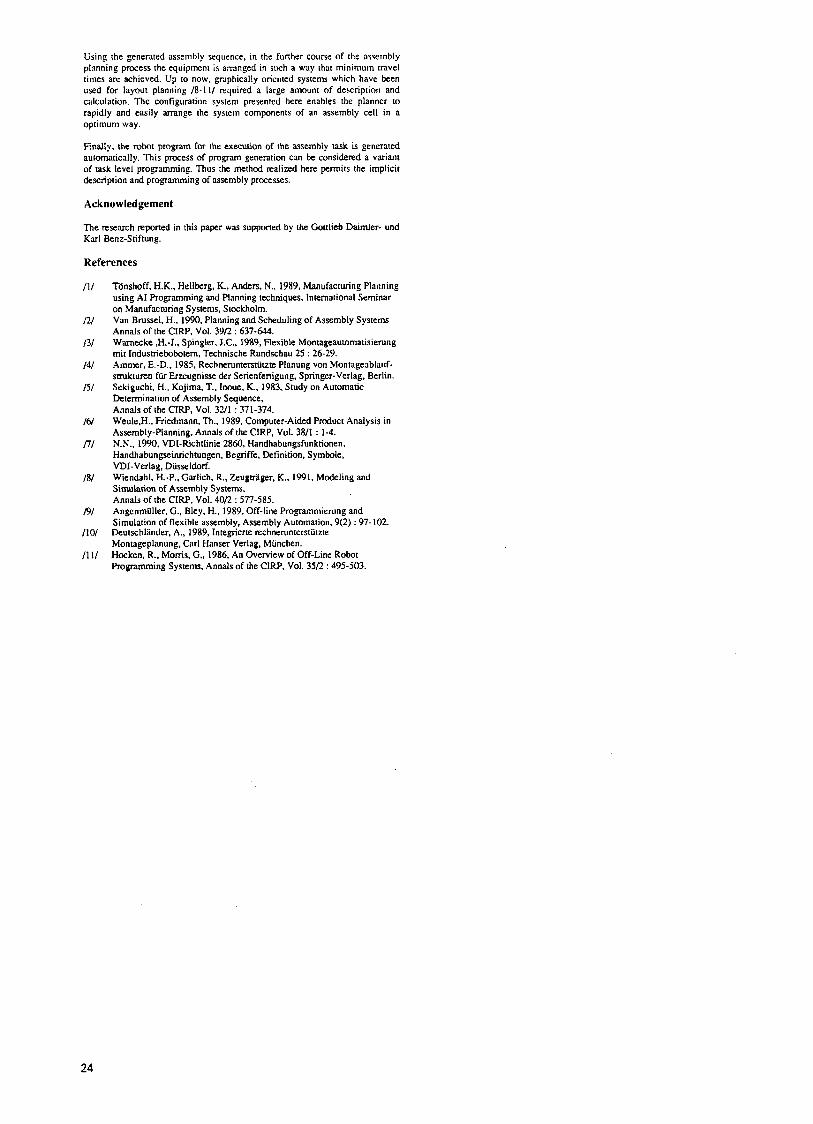
Once the assembly functions have been described using the symbols for the manipulation functions. it is necessary to convert the separate symbols for the genention of robot programs to corresponding commands in the robot programming language. This is achieved by using knowledge about the syntax and semantics of the programming language for the robot control. All commands of the programming language can be utilized for the conversion of the manipulation functions. Fig. 12 shows the subdivision of an operation using the example of joinring in different types of execution.
With the command OVERLAP several functions can be canied out in parallel, e.g. dosage during glueing. In sequential execution, e.g. spot welding and soldering. the robot remains in an unchanged condition during the duration of the operation. Assembly tasks which an not suited for execution by a robot an cvried out in special stations with specialized assembly devices. Here the robot waits outside the working m a of the assembly device until the "ready" message is received. In addition to the commands described here. robot programming languages have structured elements for program control. e.g. the classical control structures such as IF ..... THEN .... ELSE and WHILE ..... DO. The developed program generation can in the future be expanded to also allow for
Command . -- I ( Fig. 12 : Processing Model for Jointing
the inclusion of the monitoring functions, i.e. test and measurement functions during the assembly process. This way the system can in future be used to generate programs for sensor-assisted assembly within the framework of intelligent assembly. The structure of the module for generating the robot program itself is similar to post-processors commonly used for programming NC machine tools.
5 Summary
The presented planning system assist the assembly planner setting up a automated assembly system using indusmal robots. Herefore, a knowledge- based system for generating the assembly sequence was developed. The system selects the optimum assembly sequence on the basis of data on the possibilities of connecting jointing positions and on assembly technology, e.g. jointing method. technical function and jointing direction. The rules and priorities which make up the kernel of the static knowledge base. were derived from numerous analyses of assembly documents.
23
Using the generated assemhly sequence, in the further course of the assembly planning process the equipment is amnged in such a way that minimum travel times are achieved. Up to now, grdphically oriented systems which have been used for layout planning 18-111 required a luge amount of description and calculation. The configuration system presented here enables the planner to rapidly and easily arrange the system components of an assembly cell in a optimum way.
Finally. the robot program for the execution of the assembly task is generated automatically. This process of program generation can be considered a variant of task level progamming. Thus the method realized here permits the implicit description and programming of assembly processes.
Acknowledgement
The research reported in this paper was supported by the Gottlieb Daimier- und Karl Benz-Stiftung.
References
I l l
I?/
131
141
I51
161
I?/
I81
I91
/I01
/I 1/
TOnshoff. H.K., Hellberg, K., Anders, N., 1989, Manufacturing Planning using A1 Programming and Planning techniques, International Seminar on Manufacmring Systems, Stockholm. Van Brussel, H., 1990, Planning and Scheduling of Assembly Systems Annals of the CIRP, Vol. 39R : 637-644. Warnecke $I.-J., Spingler, J.C.. 1989. Flexible Montageauromatisierung mit Indusmebobotern. Technische Rundschau 25 : 26-29. Ammer, E.-D., 1985, Rechnerunrerstiitzte Planung von Montageablauf- smkturen fiir Emugnisse der Serienfemgung, Springer-Verlag. Berlin. Sekiguchi. H.. Kojima. T.. Inoue. K.. 1983, Study on Automatic Determination of Assembly Sequence, Annals of the CIRP, Vol. 3 1 1 : 371-374. WeuleP., Friedmann, Th., 1989, Computer-Aided Roduct Analysis in Assembly-Planning, Annals of the CIRP, Vol. 3811 : 1-4. N.N.. 1990. VDI-Richttinie 2860, Handhabungsfunkdonen. Handhabungseinrichtungen, Begriffe. Definition, Symbole, VDi-Verlag, Diisseldorf. Wiendahl, H.-P.. Garlich. R., Zeugtrager. K.. 1991, Modeling and Simulation of Assembly Systems, Annals of the CIW. Vol. 4OL2 : 577-585. Angenmiiller, G., Bley, H.. 1989, Off-line F’rogrammierung and Simulation of flexible assembly, Asxmbly Automation. 9(2) : 97- 102. Deutschliinder. A,. 1989. Integriene rechnerunterstiitzte Montageplanung, Carl Hans- Verlag, Munchen. Hocken, R.. Moms. G,, 1986, An Overview of Off-Line Robot Programming Systems, Annals of the CIW, Vol. 3512 : 495-503.
24