a guideline for laying of cables and installation of sleeves · a guideline for laying of cables...
TRANSCRIPT

A Guideline for Laying of Cables
and Installation of Sleeves
Accurate and faultless installation and assembly of cables and sleeves are prerequisites for a trouble-free operation.

Who is Draka Communications?
Draka Communications - part of Draka
Holding N.V. situated in Amsterdam - of-
fers a variety of reliable products in cop-
per and fibre optic technology for data
transmission and telecommunication.
Our long-term experience and knowledge
in the cable and fibre business ensures
us a major market position today.
You find Draka Communications in more
than 32 countries in Europe, Asia, North
and South America.
Cables are rarely heeded; they are ‘simply there’. General knowledge about cables is equally lacking. Very few people know what high technology is wrapped up in the inconspicuous black, grey or coloured wires. Indoor cables in particular are subjected to heavy handling by the user: office chairs are rolled over telephone connection wires, computer patch cables are trodden on by people or nibbled by their amusing pets.
Outdoor cables are affected by huge differences in temperature and high bending and pulling forces while they are being laid. The thicker the cable the stronger it may appear. However thick as well as thin wires are subject to the same physical conditions and limits.
The following pages aim to raise aware-ness about cables and explain terms such as bending radius, temperature ranges or permissible tension. Furthermore you will find instructions and tips for correct and safe installation.
ParametersInitially people have the idea, ‘We should/must modernise or expand our network’.
An engineering consultancy is hired to transform the idea into a feasible plan. Basic conditions and objectives are decided together with the customer. At the same time many technical parameters must also be considered along with the questions related to infrastructure.
During the realisation phase for the plans numerous trades work closely together. One of these is concerned with the layingof the physical network of wires or cables.
The installation company responsible for laying the cables must heed the following parameters:- temperature range of the cable,- bending radius of the cable,- maximum tension of the cable, - weight of the cable as well as- storage and cutting.
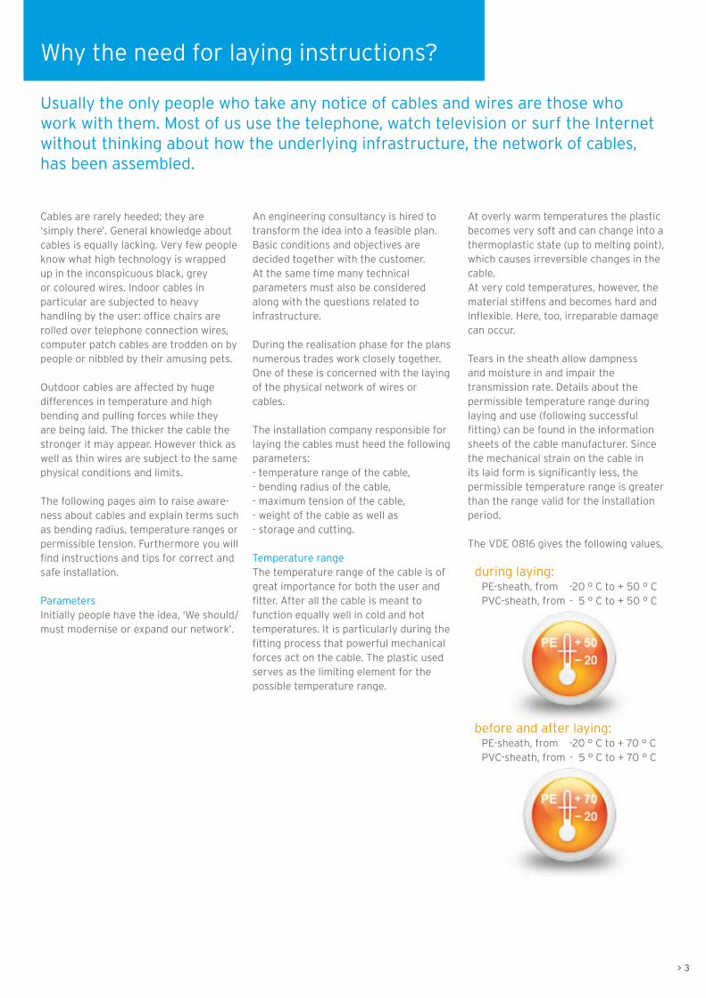
Temperature rangeThe temperature range of the cable is of great importance for both the user and fitter. After all the cable is meant to function equally well in cold and hot temperatures. It is particularly during the fitting process that powerful mechanical forces act on the cable. The plastic used serves as the limiting element for the possible temperature range.
At overly warm temperatures the plastic becomes very soft and can change into a thermoplastic state (up to melting point), which causes irreversible changes in the cable.At very cold temperatures, however, the material stiffens and becomes hard and inflexible. Here, too, irreparable damage can occur.
Tears in the sheath allow dampness and moisture in and impair the transmission rate. Details about the permissible temperature range during laying and use (following successful fitting) can be found in the information sheets of the cable manufacturer. Since the mechanical strain on the cable in its laid form is significantly less, the permissible temperature range is greater than the range valid for the installation period.
The VDE 0816 gives the following values, during laying: PE-sheath, from -20 ° C to + 50 ° C PVC-sheath, from - 5 ° C to + 50 ° C
before and after laying: PE-sheath, from -20 ° C to + 70 ° C PVC-sheath, from - 5 ° C to + 70 ° C
Why the need for laying instructions?
> 3
Usually the only people who take any notice of cables and wires are those who work with them. Most of us use the telephone, watch television or surf the Internet without thinking about how the underlying infrastructure, the network of cables, has been assembled.

Bending radiusRegarding the bending radius we distinguish between multiple and single bending (shaping into the final position). Multiple bending occurs mainly during the laying process. Cables are laid under tension around deflector rolls. Theparticular stress of multiple bending lies in the alternating stress on the materials, which can be stretched several times as well as compressed during the laying process. To prevent permanent damage there are prescribed minimum bending radii of, for example, 10 x cable external diameter for multiple bending.
The stress on the material during final bending is not characterised by alternating stress. The cable is bentinto form a final time and stays in this position for the duration of its use. The minimum bending radius in this case is, for example, 7.5 x cable external diameter. During final bending the cable can, therefore, be bent more tightly.
Exact minimum bending radii for specific cables can be found in the information sheets of the cable manufacturer.
TensionDuring laying of the cable particular attention must be paid to the maximumpossible tension. The cable is very quickly damaged by the use of too much force and must then be replaced. The maximum possible tension depends in the first place on the overall cross section and the tensile strength of the conducting materials used.For cables with steel tape or copper wire spiral armouring it is the internal copper conductors alone which determine the maximum tension! The armouring has no influence on the maximum tension or can possibly reduce it through additional weight. For armouring with steel or steel profile wires, however, the tension is determined solely by the steel and steel profile wires.
Cable weightThe cable weight of larger cable dimensions can take weights of up to more than 9 t/km (without the reel!).
Storage and cuttingCables for delivery as well as cut cables must generally be protected against moisture penetration. This best occurs through the use of shrink caps with fusible glue. Loose-fitting caps or temporary measures with plastic adhesive tape are not watertight and are unsuitable. Moisture penetration leads to corrosion and deterioration of the transmission rate. If two cable ends are to be connected with a sleeve, this must take place immediately and with protection against moisture and rain. For the period of the sleeve installation an installation tent must be erected.
4 <
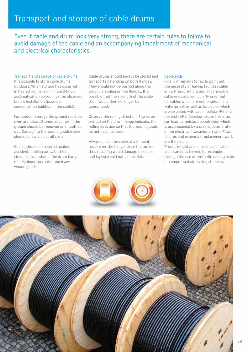
Transport and storage of cable drumsIt is possible to store cable drums outdoors. When storage has occurred in heated rooms, a minimum 24-hour acclimatisation period must be observed before installation (possible condensation build-up in the cable!).
For outdoor storage the ground must be even and clean. Stones or bumps in the ground should be removed or smoothed out. Damage to the wound goods/cable should be avoided at all costs.
Cables should be secured against accidental rolling away. Under no circumstances should the drum flangeof neighbouring cables touch any wound goods.
Cable drums should always be stored and transported standing on both flanges. They should not be pushed along the ground standing on the flanges. It is possible that the strength of the cable drum would then no longer be guaranteed.
Observe the rolling direction. The arrow printed on the drum flange indicates the rolling direction so that the wound goods do not become loose.
Always uncoil the cable at a tangent, never over the flange, since the torsion thus resulting would damage the cable and laying would not be possible.
Transport and storage of cable drums
Even if cable and drum look very strong, there are certain rules to follow to avoid damage of the cable and an accompanying impairment of mechanical and electrical characteristics.
Cable endsFinally it remains for us to point out the necessity of having faultless cable ends. Pressure-tight and impermeable cable ends are particularly essential for cables which are not longitudinally water-proof, as well as for cables which are insulated with paper, cellular-PE and foam-skin-PE. Carelessness in this area can lead to moisture penetration which is accompanied by a drastic deterioration in the electrical transmission rate. Power failures and expensive replacement work are the result. Pressure-tight and impermeable cable ends can be achieved, for example, through the use of synthetic sealing resin or compressed air sealing stoppers.
> 5

The cableCables to be laid outdoors are usually delivered on large wooden or steel drums. Manual laying is not possible due to the excessive weight. The cable drums are therefore placed in an uncoiling stand by crane or hydraulically. This stand can either be erected on a HGV trailer or separately, as seen in the picture on the right. The cable drum must have sufficient clearance from the ground and be able to turn freely. The rolling direction marked on the drum must be observed. Rolling against the rolling direction results in the loosening of the cable on the reel, which impedes uncoiling. The cable is always uncoiled at a tangent. A cable must NEVER be uncoiled over the flange. The resultant torsion can irreparably damage the cable. This is equally true for indoor cables coiled on small and light plywood reels and for ring-wound goods.
Before laying the cable, check whether the cable ends have been correctly capped and are undamaged. Missing or improperly glued caps can lead to moisture penetration during transport or laying. The same applies to any damage to the external sheath or insufficient pressure in the case of pressurised telephone cables. Moisture in the cable generally causes deterioration in the insulation resistance and the operational capacity.
A visibly damaged cable must therefore not be wound without closer inspection and clarification of the causes.
Due to their sometimes excessive weight, outdoor cables usually can not be wound by hand. Appropriate winding aids, available in diverse motorised versions, should therefore be used. Make sure that it is possible to provide evidence of the pulling in forces (tension protocol)!
There are numerous possibilities for fastening a pulling rope to a cable and this should be chosen to suit the cable type. For telecommunications cables we recommend conductor pulling with a cable pulling head.
In our example we have used a cable grip. The fastening of the pulling rope to the cable must be undertaken with care to avoid ‘losing’ the cable on the way. Corners and edges at the cross-over point from cable to rope are to be avoided otherwise the cable can easily become stuck on ledges or bumps underground. Guide swivels should be used between the cable grip and pulling rope.
The choice of the correct cable grip is dependent on the diameter of the cable.
Preparation of cable and run
A careful preparation of cable and run can avoid a number of potential reasons for damages and faults.
6 <

The runThe run is checked before laying the cable.
- Have the minimum bending radii prescribed by the cable manufacturer been followed during laying? If necessary the run must be modified.
- Are the trench, shaft, cable duct or cable pipe free of foreign bodies, sharp edges or corners and dampness or moisture?
Inspection and examination of the run prior to laying are essential. A visual check, however, is only possible for open trenches or shafts. A brush pulled through the pipe, with monitoring of any potential tension, also permits anassessment of any inaccessible areas.
If the brush becomes stuck in the pipe or if there is a temporary but significant increase in tension, this indicates dirty sections or badly fitting pipe connections. Dolly-mounted cameras can help in the inspection of a pipe or channel. Thanks to modern technology the inside of the pipe can be viewed live on screen. An accompanying meter counter gives the exact position of potential trouble spots.
> 7
Cables which are led through shafts or around corners must always run over deflector rolls. This is an effective way to avoid mechanical damage to the cable sheath.In order to achieve this some corners require a considerable measure of imagination and clever construction. It is therefore essential to have a plentiful supply of deflector rolls and to choose them correctly.When pulling horizontally rollers should also always be placed on the ground. The cable must not drag along the ground. An even pulling of the cable with the minimum possible resistance ensures quick and faultless laying.

Caterpillar tracksWhere there is sufficient space it is possible to use underground cable caterpillar tracks, which support the pulling of the cable by pushing it along with a motorised caterpillar track system. Versions with electric motor, hydraulic drive or internal combustion engine allow the use of an underground cable caterpillar track irrespective of location.
When pulling outdoor cables in cable pipe with narrow cross sections the use of cable lubricating grease should be considered. Static friction between the cable sheath and the pipe walls is minimised by the grease, which makes it easier to pull the cable into the pipe.
Trained staff and faultless equipment which is regularly checked and maintained should be a matter of course in order to guarantee safe operation. Damaged pulling ropes or bent hooks should be removed and replaced with safe ones.Pulling of the cable should occur with constant monitoring of the connected tension gauge. Suddenly increasing tension levels may indicate that the cable is obstructed or has become caught. Operators must reduce the speed of the winch or stop it in order to identify the cause. While the cable is being pulled it must be ensured that the cable is running over the installed deflector rolls. Instances of damage occurring as a result of edges, corners or stones, or vehicles driving over the cable, are to be avoided at all costs. The complete pulling process should be recorded in a protocol and any anomalies or irregularities should be noted. The tension measurements should also be added. Once cable pulling is complete, the run should, where possible, be inspected again. The cable end caps should once more be checked to ensure that they are securely fixed and watertight and should only be opened in preparation for a connection or the fitting of cable sleeves.
Pulling protocolThe protocol of tension measurements, which contains readings of the tension that occurred during pulling in, is essential to demonstrate that pulling in has been carried out correctly. If such a protocol can not be provided or if too high tension has occurred, the cable manufacturer will indicate incorrect laying and suspend the guarantee for any resultant damage.
Pulling with motorised assistance
In most cases the cable is pulled with motorised assistance. During this procedure, forces of tension result, which, depending on the type of cable to be pulled, can reach double kN figures. Particular attention must therefore be paid to work safety.
In all cases the laying instructions
of the customer and the cable
manufacturer are to be observed,
especially the data referring to
bending radius and tensile strength.

If the cable needs to be pulled in in sections, due to local conditions, no rings (pictures centre) may be laid, since this means that the cable is inappropriately twisted by 90°. Combined with high forces of tension and various deflections this can lead to destruction of the protective coating (pictures below).
The formation of loops can easily be seen in the above pictures. In narrow cable shafts and when being pulled the cables are exposed to considerable torsion, which can lead to severe damage of the cable (pictures left).
If the cable is to be laid out in sections this may only occur in so-called ‘figures of eight’ (picture above), which are set out according to the cable diameter (note the bending radius!). Torsion of the cable can then no longer occur.
Manual laying
For manual pulling in of the cable one thing that must be ensured is that the cable is on no account pulled over the flange of the drum.
> 9
For reasons of cost and space there-fore the simple lengthening of a cable is usually achieved with cable sleeves. Junctions from the cable or division of a cable into several continuing cables must be carried out with suitable distributing boxes. The connection of two or more cables within boxes or cable sleeves must be undertaken with the greatest care and be protected from dampness or moisture. A tent must be erected for the duration of the installation. Work on the sleeve and box should be undertaken quickly and without interruption.
On the following pages we provide a verbal and pictorial description of the procedure for installing a sleeve. Please note in every case the parameters of the sleeve manufacturer, the information sheets of the cable manufacturer, as well as the safety regulations of the network operator.
PreparationPreparation begins with the choice of the correct sleeve for the corresponding cable. For our example we have chosen a signal cable with reduction factor of the type Draka SIGDRAK® AJ-2Y(L)2YDB2Y 3x4x1.4 (H45) rk-group 500 as well as the matching connecting heat-shrinkable sleeve and protective heat-shrinkable sleeve.
Although we carried out the installation indoors, the same procedure applies outdoors: both cable ends must befixed to cable stands or similar devices in such a way that the work environmentis clean, tidy and protected from moisture. The cable ends should generously overlap the external edge of the sleeve. Recommendation: feel free to allow a little extra here.
Installation of sleeves
The pulled in cables are not always long enough to join together two connection points without interruption. Sometimes the position and type of laying run require the use of separate lengths of cable.
10 <
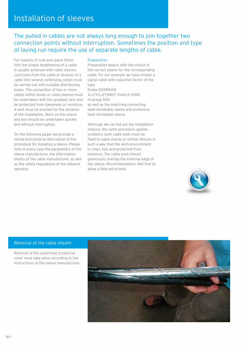
Removal of the cable sheath
Removal of the outermost protective cover must take place according to the instructions of the sleeve manufacturer.

Removal of the armouring
Removal of the armouring (steel band) occurs according to the stipulation of the sleeve manufacturer. When sawing into the steel band the shielding wires lying beneath must not be damaged. For thick cables and thick steel bands it is possible to use an iron saw with a depth marker. In our case a simple small hacksaw also served the purpose.
The upper layer of steel band is sawn into and can now be carefully unwound using a pair of pliers. Please take care with sharp edges and points: danger of injury!The same procedure is followed with the second layer of steel band. Please pay careful attention here in particular to the intactness of the shielding wires which lie beneath.The opposite cable end is to be prepared as appropriate.
> 11

Making contact with the lami-nated sheath
The inner laminated sheath is carefully stripped to the prescribed length. Damage to the core layers below can reliably be avoided by using a special stripping tool.
Installation of sleeves
12 <
The shielding wires are also shortened according to instructions. Then there are two possibilities: armouring and shielding wires can now be connected immediately or, as in our example, at the end after the connecting heat-shrinkable sleeve has been installed.
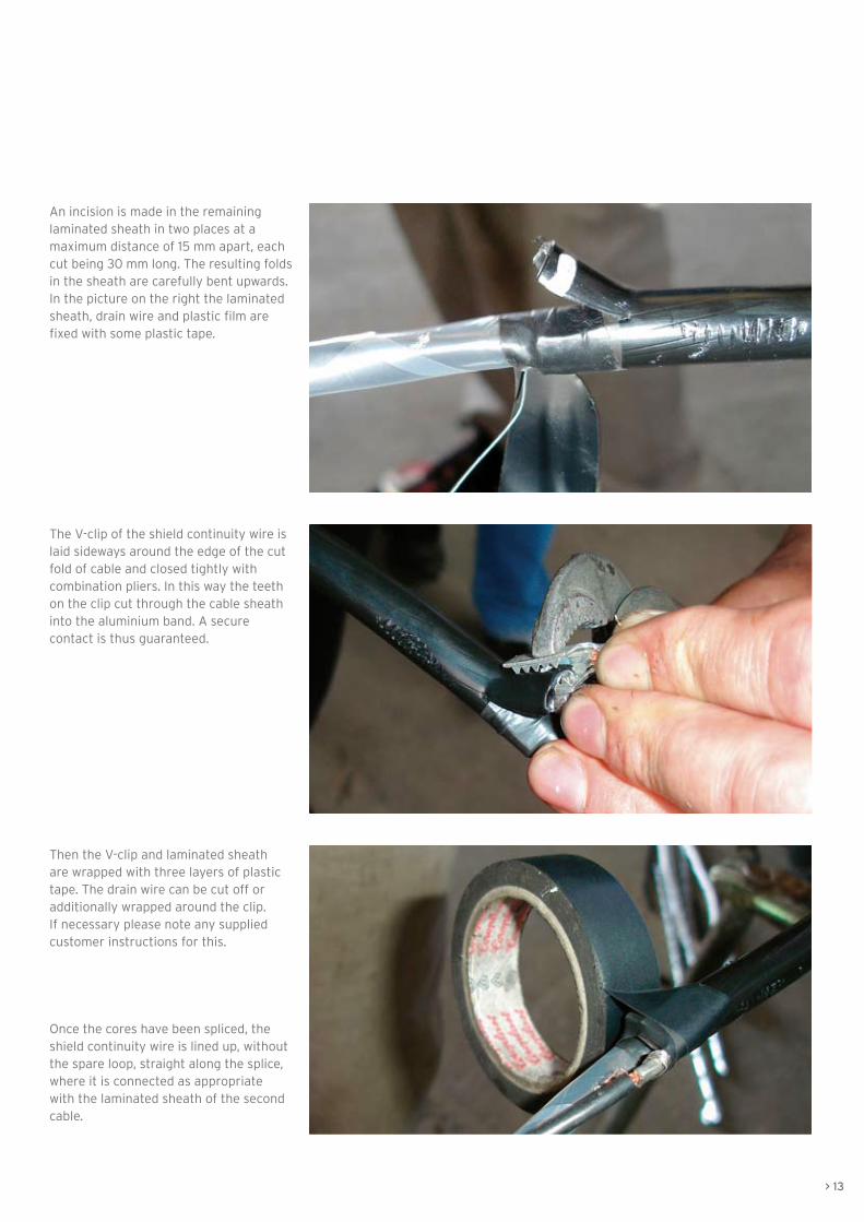
An incision is made in the remaining laminated sheath in two places at a maximum distance of 15 mm apart, each cut being 30 mm long. The resulting folds in the sheath are carefully bent upwards.In the picture on the right the laminated sheath, drain wire and plastic film are fixed with some plastic tape.
The V-clip of the shield continuity wire is laid sideways around the edge of the cut fold of cable and closed tightly with combination pliers. In this way the teeth on the clip cut through the cable sheath into the aluminium band. A secure contact is thus guaranteed.
Then the V-clip and laminated sheath are wrapped with three layers of plastic tape. The drain wire can be cut off or additionally wrapped around the clip. If necessary please note any supplied customer instructions for this.
Once the cores have been spliced, the shield continuity wire is lined up, without the spare loop, straight along the splice, where it is connected as appropriate with the laminated sheath of the second cable.
> 13
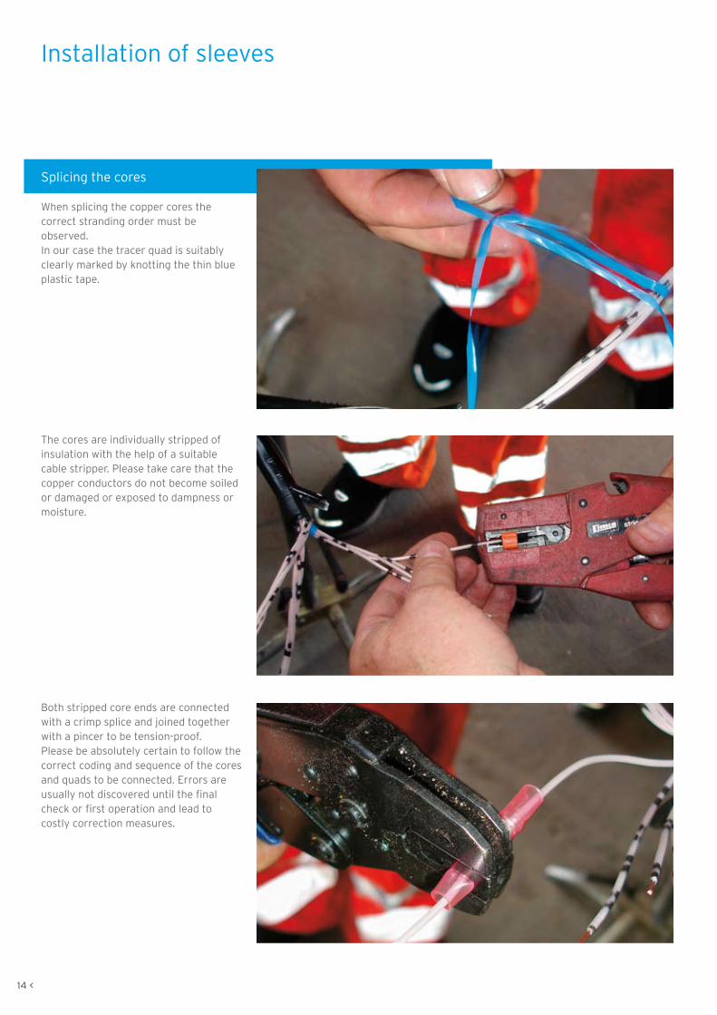
Splicing the cores
When splicing the copper cores the correct stranding order must be observed. In our case the tracer quad is suitably clearly marked by knotting the thin blue plastic tape.
The cores are individually stripped ofinsulation with the help of a suitable cable stripper. Please take care that the copper conductors do not become soiled or damaged or exposed to dampness or moisture.
Both stripped core ends are connected with a crimp splice and joined together with a pincer to be tension-proof.Please be absolutely certain to follow the correct coding and sequence of the cores and quads to be connected. Errors are usually not discovered until the final check or first operation and lead to costly correction measures.
Installation of sleeves
14 <

After installation the crimp splices are carefully shrunk with a burner. Released glue and the closely fitting plastic protect the bare copper joint mechanically and against dampness.
This is what the splices look like following successful shrinkage. When a connection has been shrunk correctly, some glue will seep out at the sides.
Staggered splices result in a narrow joint. If you have not already done so, you should now connect the shield continuity wire with the laminated sheath of the opposite cable.
> 15

Preparation of the inner connect-ing heat-shrinkable sleeve
The two laminated sheaths facing the core splices are now cleaned with a cleansing cloth so that a 150 mm wide area is oil-free.
Once the oil has been removed the laminated sheath is roughened across the cable axis with an emery cloth. Any pitted areas in the sheath must also be roughened.
Caution:
The given sequence (removal
of oil, then roughening) must
be observed!
Following this the cleaned and roughened areas are heated with a burner until they are hand-hot.
16 <
Installation of sleeves

Before installation of the actual heat-shrinkable sleeve, the drying agents supplied with the packaging should be fixed around the core splice with adhesive tape.Please do not wrap the entire drying agent with isolating tape as this will prevent it from fulfilling its function. Simple wrapping to keep the agent in place is sufficient.
> 17
The connecting heat-shrinkable sleeve
The protective padding should be rolled together before the installation (pre-formed) and then laid as tightly as possible overlapping the core splice and secured with adhesive tape.
The lamellar areas of the protective padding should be unwound with adhesive tape.

Line up centrally the seal for the heat-shrinkable sleeve. It must extend beyond the protective padding by the same length on each side.It is helpful to mark at least on one side of the laminated sheath how far the seal will extend.
The seal is laid completely around the splice and the sealing edge pulled up.
When shrinking the sleeve, begin in the middle. For this procedure heat the complete area of the sleeve and shrink it towards one end. Then work on the other end. Move the flame back and forth evenly and continuously to avoid localised burning.
Installation of sleeves
18 <

The shrinking process is over when the seal has evenly shrunk, the green colour pigment in the sleeve material has disappeared and the white indicator line is easily visible under the sealing edge. At the ends small amounts of glue must be seeping out of the cable. Caution: the shrunken seal and the seal-ing edge retain the heat for a very long time (danger of burns!). As it cools the sleeve shrinks a little further.
> 19
Connecting the armouring
Before connecting the armouring and the shielding wires, the exposed areas of the latter should be cleaned metallically bright and roughened. When doing this, please also heed the armouring layer beneath.
The copper fabric tape should be wound according to instructions in a single layer around the armouring and shielding wires. The remaining fabric tape should be cut off and retained.

The supplied contact plates are pre-formed according to instructions, laid around the copper fabric tape and wrapped and secured with one layer of the copper fabric tape (with a max. 5 mm overlap).
The earth wire is cut to 1.5 times the length of the removed section of the outer protective coating, and pulled over the neighbouring protective tube in such a way that approximately 100 mm are left bare and free at both ends of the earth strand. The end of the earth strand is fanned out and, flush with the removed edge of the armouring, laid flat onto the copper fabric tape and secured close to the end of the removed edge with a roll spring. The earth wire is fixed with the second roll spring with three layers, then pulled back and secured with the remaining layers of the roll spring.
At the end of installation the earth wire looks like this. The second side should be dealt with in the same way.
20 <
Installation of sleeves
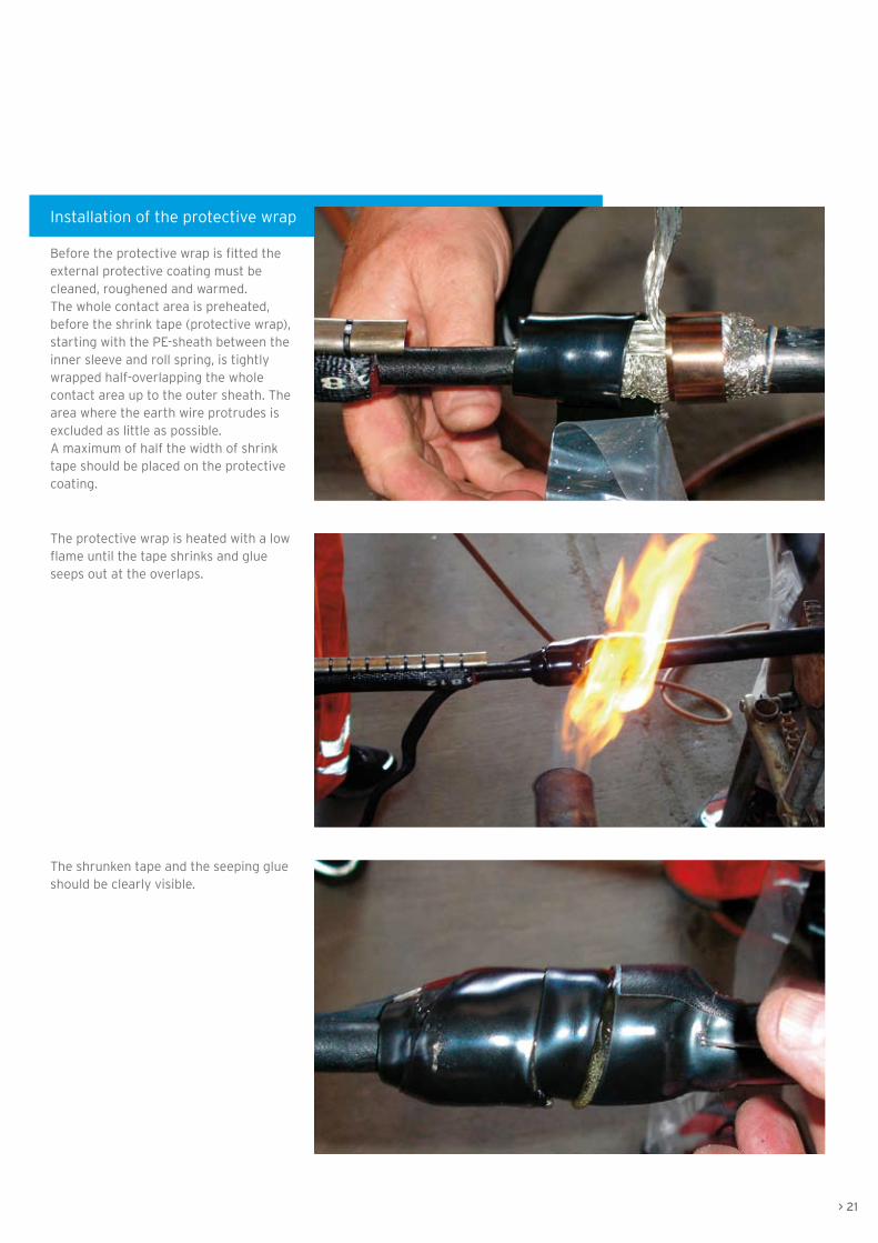
Installation of the protective wrap
Before the protective wrap is fitted the external protective coating must be cleaned, roughened and warmed. The whole contact area is preheated, before the shrink tape (protective wrap), starting with the PE-sheath between the inner sleeve and roll spring, is tightly wrapped half-overlapping the whole contact area up to the outer sheath. The area where the earth wire protrudes is excluded as little as possible.A maximum of half the width of shrink tape should be placed on the protective coating.
The protective wrap is heated with a low flame until the tape shrinks and glue seeps out at the overlaps.
The shrunken tape and the seeping glue should be clearly visible.
> 21

Installation of the protective heat-shrinkable sleeve
The earth wire is laid radially around the splice and secured with some plastic tape. Then the metal protective padding should be tightly laid around the inner sleeve, centrally and overlapping, and secured with adhesive tape. The conical ends should be carefully wrapped with plastic adhesive tape.
The outer sheath is cleaned until it is oil-free, roughened across the cable axis and then heated with a low flame to hand-hot temperature.
The wrapping on the conical ends of the metal protective padding should be clearly visible. The seal for the heat-shrinkable sleeve is laid centrally over the connecting point and the projection marked on at least one side of the laminated sheath.
22 <
Installation of sleeves
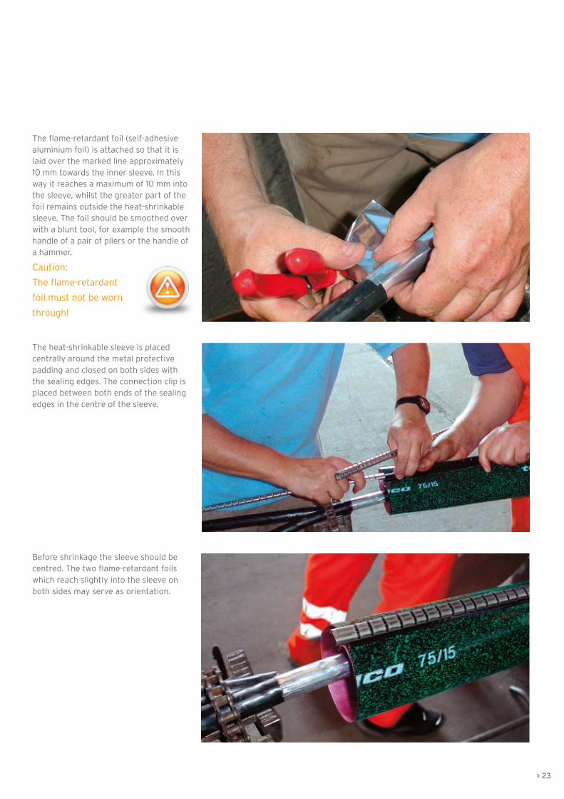
The flame-retardant foil (self-adhesive aluminium foil) is attached so that it is laid over the marked line approximately 10 mm towards the inner sleeve. In this way it reaches a maximum of 10 mm into the sleeve, whilst the greater part of the foil remains outside the heat-shrinkable sleeve. The foil should be smoothed over with a blunt tool, for example the smooth handle of a pair of pliers or the handle of a hammer.
Caution:
The flame-retardant
foil must not be worn
through!
The heat-shrinkable sleeve is placed centrally around the metal protective padding and closed on both sides with the sealing edges. The connection clip is placed between both ends of the sealing edges in the centre of the sleeve.
Before shrinkage the sleeve should be centred. The two flame-retardant foils which reach slightly into the sleeve on both sides may serve as orientation.
> 23
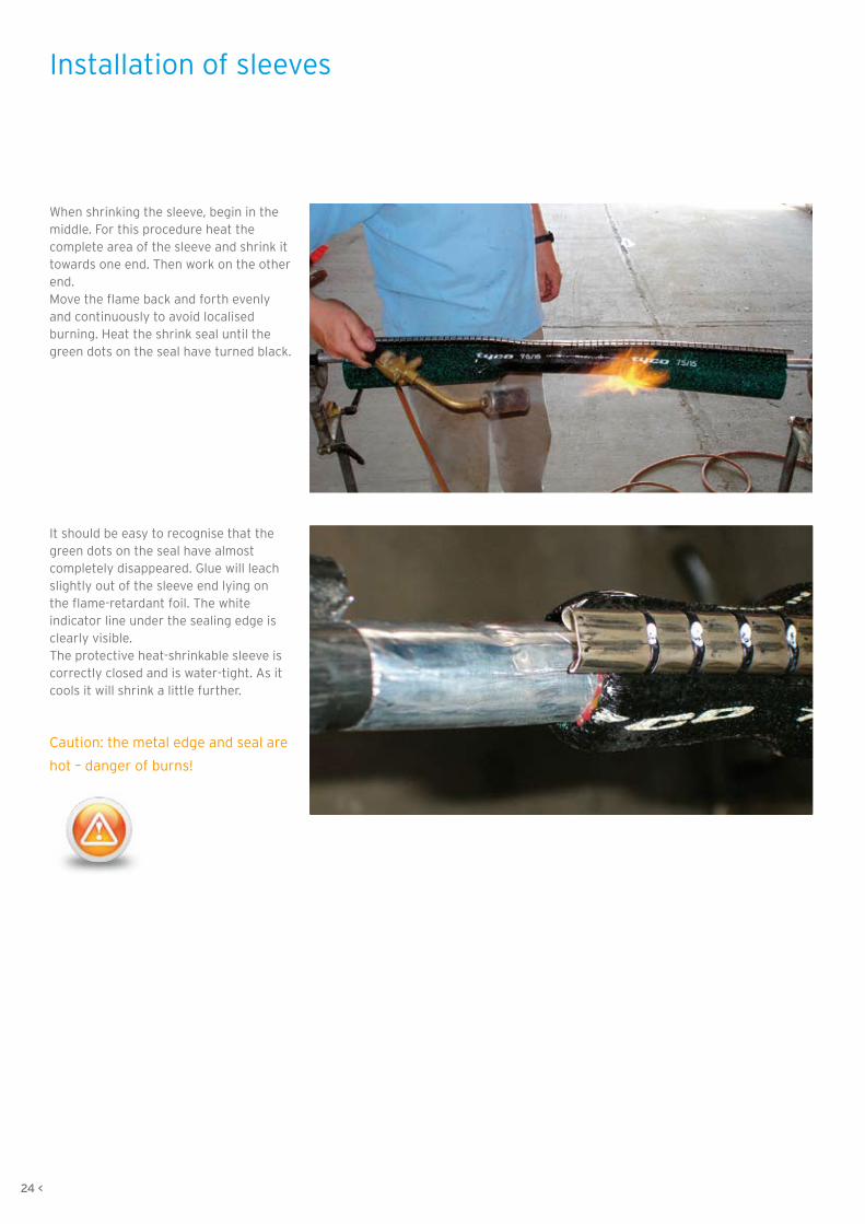
When shrinking the sleeve, begin in the middle. For this procedure heat the complete area of the sleeve and shrink it towards one end. Then work on the other end. Move the flame back and forth evenly and continuously to avoid localised burning. Heat the shrink seal until the green dots on the seal have turned black.
It should be easy to recognise that the green dots on the seal have almost completely disappeared. Glue will leach slightly out of the sleeve end lying on the flame-retardant foil. The white indicator line under the sealing edge is clearly visible. The protective heat-shrinkable sleeve is correctly closed and is water-tight. As it cools it will shrink a little further.
Caution: the metal edge and seal are
hot – danger of burns!
24 <
Installation of sleeves

Installation of rail foot cables
The installation of rail foot cables is a lengthy and expensive process. Trenches need to be dug, and channels or troughs need to be put in place. Until a few years ago the only alternative available was to hang the cable from masts or poles.
Working in close cooperation with Photon Meissener Technologies GmbH in Meißen, who develop and manufacture the fastening and junction elements, Draka has developed a rail foot cable which meets the high standards necessary for rail foot installation. Greatest consideration was given to the durability and reliability of the cable, which is subject to enormous vibration forces in the rail foot position.
Considerable care must be taken when attaching the cable to the rail foot. Only the combination of the highest quality cable and fastening elements can guarantee trouble-free and long-lasting operation.
In the following we would like to give some important tips on the fastening and fitting of rail foot cables.
In every instance
- the installation directions of the
client,
- the instructions of the cable
manufacturer with regard to the
bending radius and tensile
strength, as well as
- the assembly guidelines given
by the rail foot clamp and rail foot
junction manufacturer,
must be heeded.
Rail foot cables are only
permitted on non-electrified
sections and authorised up to a
maximum track speed of 160 km/h.
Installation temperaturesDue to the medium expansion potential of the cable, the installation and assembly of the cable at the rail foot is only possible at a temperature range of + 5 °C to + 25 °C.For installation and assembly in the ground, or in trough and pipe channels, the temperature range is - 5 °C to + 50 °C.
PreparationBefore installation of the cable the rail foot area must be given a visual inspection. This is to ensure that along the rail foot there are no heavily soiled parts, foreign bodies or sharp edges, such as welded joints for example. The following works need to be scheduled accordingly.
The installation of cable at welded joints (see sequence of pictures on the right) in tracks is in fact theoretically possible, but over time the cable would suffer damage due to movement and vibration. It makes sense to use a protection on these places.
The welded joints are to be filed down to smoothen sharp edges and welding beads in order to avoid possible future damage. The welding joint itself may only be carefully reduced externally so that the physical stability of joint will not be affected. After the grinding the cable should be covered by a protective pipe in this place. This pipe can be fixed with two rail foot clamps to the left and right on the cable or directly on the pipe. A permanent protection is then guaran-teed.

InstallationLay the cable down outside the area of the tracks and align it. When doing so the cable must not be unwound over the flange of the delivery drum. In that case loops will occur which cannot be compensated during the lay. Lay the cable along the external side of the rail foot. When installing the cable, ensure that there is a reserve length of approximately 5 m on each side.
If local conditions are met, the cable may also be laid directly along the external side of the rail foot from a slow moving railcar.
Installation of the rail foot cable and fastening to the rail foot should take place from one end only or from the middle towards both ends. If installation is attempted from both ends, loops will occur in the cable. In this case damage to the cable by passing trains could not be ruled out.
FasteningThe cable may only be fastened with rail foot clamps which are approved for the particular type of track, since the permissible downward pressure is dependent on the type of cable and the track shape.
We recommend allowing one rail foot clamp in at least every second sleeper spacing and never fitting more than one single cable under the rail foot clamps at the rail foot.In principle the installation of two rail foot cables under one rail foot clamp is possible. Special attention need to be paid to the diameter of the cable and the guidelines of the manufacturer of rail foot clamps. A combination of very small with larger rail foot cables shall be avoided as the expansion of both cables due to temperature changes are different and will result in loops. Furthermore the smaller cable shall always be installed on top.
At earthings, points, track magnets, level-crossings or in the case of a necessary joint the rail foot cable should be led away from the track with the help of a rail foot junction authorised and released by the rail operator. The cable should then be laid in the ground or in troughs, or at least be placed inside a protective pipe. For this procedure the minimum bending radius of the cable, as stipulated by the manufacturer, must be observed.
The placing of joints directly at the rail foot is not permitted. Instead the cable ends to be joined must be led away from the rail foot and brought together in a sleeve next to the tracks.
Installation of rail foot cables
Inadequate installation creates loops of the lower cable.
Ideal installation
Inadequate installation creates loops
We hope we have been able to give you some guidance in the laying and installation of outdoor cables. If you have further suggestions, please send your ideas by e-mail to [email protected].
Quality and accuracyAccuracy during preparation of run, laying of cable and installation of sleeve pays. The little additional work is in no relation to the cost which might arise in case of a complaint.
Chose products of well-known manufacturers and you have best conditions for a proper installation.
DisclaimerThe above laying and installation instructions are correct to the best of our knowledge and have resulted from consideration of current and recognised techniques and technologies. They are intended as instructions for the correct laying and installation of outdoor cables. They have no exclusive validity.
Information sheets provided by cable and sleeve manufacturers must be observed, as must laying or installation directions supplied by the network operator or installation companies.
Any company contracted to undertake the work has sole responsibility for the pulling in and laying of the cable as well as the installation of cable sleeves or branch joints. We accept no liability for any damage which occurs during pulling in or sleeve installation despite or as a result of following these instructions.
> 27
A final word
In any case observe the valid regulations for the prevention of industrial accidents.
Installation is to be executed from qualified personnel only.

08
.20
10 ©
Dra
ka C
om
mu
nic
atio
ns.
Su
bje
ct t
o c
han
ges
wit
ho
ut
pri
or
no
tice
.
www.draka.com/communications
We make communication technology work, by serving you in every way to realize your leading edge network solution
Austria*Trillergasse 8A-1210 WienPhone: +43 1 294 0095 16Telefax: +43 1 294 0095 [email protected]*) including: Hungary, Czech Repu-blic, Slovakia,Slovenia, Albania, Macedonia,Romania and Bulgaria
DenmarkPriorparken 833DK-2605 BroendbyPhone: +45 43 48 20 50Telefax: +45 43 48 26 [email protected]
Finland*Kimmeltie 1FIN-02110 EspooPhone: +358 10 56 61Telefax: +358 10 56 63 [email protected]*) including: Baltic countries, Poland, Ukraine, Belarus, Georgia and Armenia
FranceLe Sophocle - Parc de Algorithmes9, Avenue du MaraisF-95100 ArgenteuilPhone: +33 1 34 34 41 30Telefax: +33 1 30 76 40 [email protected]
GermanyFriedrichshagener Straße 29-36D-12555 BerlinPhone: +49 30 654 85 760Telefax: +49 30 654 85 [email protected]
Germany*Piccoloministraße 2D-51063 KölnPhone: +49 221 677 0Telefax: +49 221 677 [email protected]*) including: Switzerland
Netherlands(HQ - Comteq Cable Division)De Boelelaan 7 - Bulding Officia INL-1083 HJ AmsterdamPhone: +31 20 56 89 865Telefax: +31 20 56 89 [email protected]
Netherlands(HQ - Comteq Fibre Division)Zwaanstraat 1NL-5651 CA EindhovenPhone: +31 40 295 87 00Telefax: +31 40 295 87 [email protected]
Netherlands*Zuidelijk Halfrond 11NL-2801 DD GoudaPhone: +31 182 59 21 00Telefax: +31 182 59 22 [email protected]*) including: Belgium and Luxem-bourg
Norway*Kjerraten 16N-3013 DrammenPhone: +47 32 24 90 00Telefax: +47 32 24 91 16*) including: Sweden and Iceland
Romania*Draka Iberica PlantRomanian Representative OfficeCalea Floreasca, nr 169A, Floor 4Regus Biz CenterRO-014472 Bukarest, Sector 1Phone: +40 31 860 22 65Fax: +40 31 860 21 [email protected]*) including: Greece and Moldova
Russia Neva Cables Ltd.8th Verkhny pereulok, 10RUS-St. Petersburg, 194292Phone: +7 812 592 84 79Telefax: +7 812 592 77 [email protected]
Draka Communications has offices and production facilities all over the world. To get in touch with us and find out how we can help you build your network, visit our website at www.draka.com/communications or contact us.
SpainAv. de Bilbao 72E-39600 Maliaño - CantabriaPhone: +34 942 24 71 00Telefax: +34 942 24 71 [email protected]
Spain*Can Vinyalets núm. 2E-08130 Sta. Perpetua de la Mogoda - BarcelonaPhone: +34 935 74 83 83Telefax: +34 935 60 13 [email protected]*) including: Portugal and Italy
Turkey*Cumhuriyet Cad. Yedek Reis Sok.No. 9 Ergun Plaza K.4 KavcikTR-34810 Beykoz IstanbulPhone: +90 216 682 80 01Telefax: +90 212 537 66 [email protected]*) including: all other countries in Africa and Middle East
United Kingdom*Crowther RoadCrowther Industrial Estate, UK-NE38 0AQ Washington, Tyne and Wear,Phone: +44 191 415 50 00Telefax: +44 191 415 82 [email protected]*) including: Ireland
Our European Production Centres:
DenmarkBroendby
FinlandOulu
FranceCalaisHaisnes
GermanyBerlinNürnberg
NetherlandsEindhovenDelfzijl
RussiaSt. Petersburg
SlovakiaPresov
SpainSantander
United KingdomWashington, Tyne and Wear