a guide to mechanical equipment for healthy indoor environments
TRANSCRIPT
esearch ReportR
HEALTHY
HOUSING AND
COMMUNITIES
SERIES
A GUIDE TO MECHANICAL EQUIPMENT
FOR HEALTHY INDOOR ENVIRONMENTS

CMHC—Home to Canadians
Canada Mortgage and Housing Corporation (CMHC) is Canada’s national housing agency.We contribute toimproving the living conditions and the well-being of Canadians.
Our housing finance activities centre around giving Canadians access to affordable financing solutions. Themain tool to achieve this goal is our mortgage loan insurance program.
We help lower-income households — seniors, people with disabilities,Aboriginals, women and children fleeingfamily violence, youth at risk, and individuals who are homeless or at risk of homelessness — to gain accessto safe, affordable housing.
Through our research, we encourage innovation in housing design and technology, community planning,housing choice and finance.We offer a wide variety of information products to consumers and the housingindustry to help them make informed purchasing and business decisions.
We also work with our government partners and industry to promote Canadian products and expertise inforeign markets, thereby creating jobs for Canadians here at home.
In everything that we do, we are committed to helping Canadians access a wide choice of quality, affordablehomes, and making vibrant and sustainable communities a reality across the country. CMHC is home toCanadians.
Visit us at www.cmhc.ca
You can also reach us by phone at 1 800 668-2642 (outside Canada call 613 748-2003)By fax at 1 800 245-9274 (outside Canada 613 748-2016)
Canada Mortgage and Housing Corporation supports the Government of Canadapolicy on access to information for people with disabilities. If you wish to obtainthis publication in alternative formats, call 1 800 668-2642.
A GUIDE TO MECHANICAL EQUIPMENT FORHEALTHY INDOOR ENVIRONMENTS
byDavid Rousseau,Archemy Consulting Ltd.
Dara Bowser, Bowser Technical Inc.Chris Mattock, Habitat Design + Consulting Ltd.
forVirginia Salares, project manager
Canada Mortgage and Housing Corporation
CMHC offers a wide range of housing-related information, For details, call 1 800 668-2642 or visit ourWeb site at www.cmhc.ca
Cette publication est aussi disponible en français sous le titre : Guide d’équipement mécanique pour un environnement intérieur sain, 62063
This research project was (partially) funded by Canada Mortgage and Housing Corporation ("CMHC"). Thecontents, views and editorial quality of this report are the responsibility of the author(s) and CMHC acceptsno responsibility for them or any consequences arising from the reader's use of the information, materials and techniques described herein.
National Library of Canada Cataloguing in Publication Data
Rousseau, David
Main entry under title:
A guide to mechanical equipment for healthy indoor environments
Issued also in French under title: Guide d’équipement mécanique pour un environnemnt intérieur sainIncludes bibliographical references
ISBN 0-660-18498-2Cat. No. NH15-343/2001E
1. Dwellings – Heating and ventilation – Health aspects – Handbooks, manuals, etc.2. Heating – Equipment and supplies – Handbooks, manuals, etc.3. Ventilation – Equipment and supplies – Hankbooks, manuals, etc.4. Water – Purification – Equipment and supplies – Handbooks, manuals, etc.5. Housing and health – CanadaI. Mattock, ChrisII. Bowser, DaraIII. Canada Mortgage and Housing CorporationIV. Title
TD883.17.R68 2001 613.5 C2001-980138-6
© 2001 Canada Mortgage and Housing Corporation. All rights reserved. No portion of this book may be reproduced, stored in a retrieval system or transmitted in any form or by any means, mechanical, electronic, photocopying, recording or otherwise without the priorwritten permission of Canada Mortgage and Housing Corporation. Without limiting the generality of the foregoing no portion of this book may be translated from English into any other language without the priorwritten permission of Canada Mortgage and Housing Corporation.
Revised and reprinted 2003Printed in CanadaProduced by CMHC
i
PURPOSE
A house consists of two major components—the house envelope and themechanical equipment. The performance of the house over time depends,to a large extent, on the soundness and quality of the house envelope andthe mechanical equipment. The occupants also have a major contributionto the house performance. The occupancy factors include density (highor low), the habits, hobbies and lifestyles of the occupants, the kinds andamount of furnishings and belongings they bring and store in the house,and how they maintain and operate both the house and equipment.
A book on building materials, Building Materials for theEnvironmentally Hypersensitive, was prepared to assist homeowners,architects and builders in selecting building materials for residentialconstruction. A Guide to Mechanical Equipment for Healthy IndoorEnvironments was written for the same purpose, but the focus is onmechanical equipment. It discusses residential heating and coolingsystems, ventilation, filtration and water purification.
Homeowners or contractors who are building a new house can use theguide for selecting new equipment. Similarly, those who are planningretrofits can compare different equipment to replace older, less efficientsystems. The guide also discusses balanced heat recovery ventilationsystems, which every homeowner should know about.
Throughout the guide, references have been made to the needs ofenvironmentally hypersensitive individuals. While the average persontypically applies capital and operating cost considerations in selectingequipment, hypersensitive individuals rank the potential impact of theequipment on air quality or health high on their criteria list. Informationpertinent to hypersensitive individuals is presented in italics, to make iteasily recognized from the general discussion.
Virginia SalaresSenior ResearcherResearch Division
Tel. (613) 748-2032Fax (613) 748-2402

ii
ACKNOWLEDGEMENTS
We are indebted to the Heating, Refrigerating and Air ConditioningInstitute for reviewing the manuscript. Peter Russell’s invaluablesuggestions are also acknowledged.
iii
This publication summarizes current information on heating (both spaceand hot water heating), cooling and ventilation systems and equipmentused in low-rise, residential buildings with regards to their effect onindoor air quality. An additional discussion of water purification systemsis also presented. The publication is intended to be an information sourceprimarily for environmentally hypersensitive individuals and, second, forthe general public and the homebuilding industry as a reference onmechanical systems.
The document provides background information for the reader bypresenting definitions of specialized terminology used in the publicationand with a discussion of a house as a system. This latter discussionshows how the operation of mechanical equipment and the indoor airquality in a home are affected by other elements such as insulation, air barriers and the types of interior finishes used.
Various types of heating, cooling, ventilation and air filtration systemsare presented with a discussion of how they affect the indoor air qualityof a home. Retrofitting existing heating systems to improve indoor airquality is also addressed. A discussion focussed on the specific needs of the environmentally hypersensitive is presented at the end of each section.
The report concludes with a section on water quality and the types of water treatment systems available for residential applications. Theappendices contain lists of suppliers of heating, cooling, ventilation and water treatment equipment indexed both by type of equipment and by supplier.
EXECUTIVE SUMMARY
v
TABLE OF CONTENTS
1. INTRODUCTION . . . . . . . . . . . . . . . . . . . . . . . . . . . . . . . . . . . . . . . . . . . . . . . . . . . . . .1
How to Use the Guide . . . . . . . . . . . . . . . . . . . . . . . . . . . . . . . . . . . . . . . . . . . . . . . . . . . .1
2. THE HOUSE AS A SYSTEM . . . . . . . . . . . . . . . . . . . . . . . . . . . . . . . . . . . . . . . . . . . . . .3
3. HEATING AND COOLING . . . . . . . . . . . . . . . . . . . . . . . . . . . . . . . . . . . . . . . . . . . . . . .8
Energy Sources . . . . . . . . . . . . . . . . . . . . . . . . . . . . . . . . . . . . . . . . . . . . . . . . . . . . . . . . . .8
Furnace Types Based on Fuel . . . . . . . . . . . . . . . . . . . . . . . . . . . . . . . . . . . . . . . . . . . . . . .9
Forced-Air Systems . . . . . . . . . . . . . . . . . . . . . . . . . . . . . . . . . . . . . . . . . . . . . . . . . . . . . .13
Fan Coil Systems . . . . . . . . . . . . . . . . . . . . . . . . . . . . . . . . . . . . . . . . . . . . . . . . . . . . . . . .20
Heat Pumps and Central Air Conditioning Systems . . . . . . . . . . . . . . . . . . . . . . . . . . . . . .22
Convection Heating Systems . . . . . . . . . . . . . . . . . . . . . . . . . . . . . . . . . . . . . . . . . . . . . . .25
Radiant Heating Systems . . . . . . . . . . . . . . . . . . . . . . . . . . . . . . . . . . . . . . . . . . . . . . . . . .27
Passive Solar Heating Systems . . . . . . . . . . . . . . . . . . . . . . . . . . . . . . . . . . . . . . . . . . . . . .31
Portable Heating and Air Conditioning Equipment . . . . . . . . . . . . . . . . . . . . . . . . . . . . . . .32
Boilers . . . . . . . . . . . . . . . . . . . . . . . . . . . . . . . . . . . . . . . . . . . . . . . . . . . . . . . . . . . . . . .35
Central Heat Pumps/Air Conditioners . . . . . . . . . . . . . . . . . . . . . . . . . . . . . . . . . . . . . . . .37
Domestic Water Heaters . . . . . . . . . . . . . . . . . . . . . . . . . . . . . . . . . . . . . . . . . . . . . . . . . . .39
Electric Radiant Heating . . . . . . . . . . . . . . . . . . . . . . . . . . . . . . . . . . . . . . . . . . . . . . . . . .40
Enclosed Fan Motors . . . . . . . . . . . . . . . . . . . . . . . . . . . . . . . . . . . . . . . . . . . . . . . . . . . . .41
Fan Coil Heating/Cooling Units . . . . . . . . . . . . . . . . . . . . . . . . . . . . . . . . . . . . . . . . . . . . .42
Furnaces . . . . . . . . . . . . . . . . . . . . . . . . . . . . . . . . . . . . . . . . . . . . . . . . . . . . . . . . . . . . . .44
Heating/Air Conditioning Ducts and Connectors . . . . . . . . . . . . . . . . . . . . . . . . . . . . . . . .45
Hot Water Radiant Heating . . . . . . . . . . . . . . . . . . . . . . . . . . . . . . . . . . . . . . . . . . . . . . . .46
Humidifiers . . . . . . . . . . . . . . . . . . . . . . . . . . . . . . . . . . . . . . . . . . . . . . . . . . . . . . . . . . . .47
Isolated Fan Motors . . . . . . . . . . . . . . . . . . . . . . . . . . . . . . . . . . . . . . . . . . . . . . . . . . . . . .48
Low-Temperature Convection Heaters . . . . . . . . . . . . . . . . . . . . . . . . . . . . . . . . . . . . . . . .48
Low-Temperature Portable Heaters . . . . . . . . . . . . . . . . . . . . . . . . . . . . . . . . . . . . . . . . . .49
Passive Solar Heat . . . . . . . . . . . . . . . . . . . . . . . . . . . . . . . . . . . . . . . . . . . . . . . . . . . . . . .50
Portable/Window or Wall Air Conditioners and CompactSplit-System Air Conditioners . . . . . . . . . . . . . . . . . . . . . . . . . . . . . . . . . . . . . . . . . . . . . .51
4. VENTILATION AND FILTRATION BASICS . . . . . . . . . . . . . . . . . . . . . . . . . . . . . . . .52
Exhausting Pollutants at Source . . . . . . . . . . . . . . . . . . . . . . . . . . . . . . . . . . . . . . . . . . . . .52
Natural vs. Mechanical Ventilation . . . . . . . . . . . . . . . . . . . . . . . . . . . . . . . . . . . . . . . . . . .52
Ventilation Effectiveness and Distribution . . . . . . . . . . . . . . . . . . . . . . . . . . . . . . . . . . . . .52
Ventilation System Operation . . . . . . . . . . . . . . . . . . . . . . . . . . . . . . . . . . . . . . . . . . . . . . .53
Types of Mechanical Ventilation . . . . . . . . . . . . . . . . . . . . . . . . . . . . . . . . . . . . . . . . . . . .56
Central Exhaust Ventilator . . . . . . . . . . . . . . . . . . . . . . . . . . . . . . . . . . . . . . . . . . . . . . . . .64
Demand-Controlled CEV System . . . . . . . . . . . . . . . . . . . . . . . . . . . . . . . . . . . . . . . . . . . .65
Recirculating Central Ventilation Systems (RCVs) . . . . . . . . . . . . . . . . . . . . . . . . . . . . . . .67
Balanced Ventilation Systems (Heat Recovery Ventilators) . . . . . . . . . . . . . . . . . . . . . . . .69
Air-Inlet Devices . . . . . . . . . . . . . . . . . . . . . . . . . . . . . . . . . . . . . . . . . . . . . . . . . . . . . . . .75
Central Exhaust Ventilator . . . . . . . . . . . . . . . . . . . . . . . . . . . . . . . . . . . . . . . . . . . . . . . . .76
Duct Fans . . . . . . . . . . . . . . . . . . . . . . . . . . . . . . . . . . . . . . . . . . . . . . . . . . . . . . . . . . . . .76
Ducts, Flexible Duct and Sealers, Duct Insulation . . . . . . . . . . . . . . . . . . . . . . . . . . . . . . .77
Exhaust Fans . . . . . . . . . . . . . . . . . . . . . . . . . . . . . . . . . . . . . . . . . . . . . . . . . . . . . . . . . . .78
Heat Recovery Ventilators . . . . . . . . . . . . . . . . . . . . . . . . . . . . . . . . . . . . . . . . . . . . . . . . .78
Kitchen Range Exhaust (Outside Vented) . . . . . . . . . . . . . . . . . . . . . . . . . . . . . . . . . . . . . .85
Recirculating Central Ventilator . . . . . . . . . . . . . . . . . . . . . . . . . . . . . . . . . . . . . . . . . . . . .85
Supplementary Ventilation Air Filtration for HRVs . . . . . . . . . . . . . . . . . . . . . . . . . . . . . .86
Registers, Grilles and Diffusers . . . . . . . . . . . . . . . . . . . . . . . . . . . . . . . . . . . . . . . . . . . . .87
5. HEATING AND VENTILATING SYSTEM RETROFITS . . . . . . . . . . . . . . . . . . . . . .88
Adapting the Warm-Air Furnace . . . . . . . . . . . . . . . . . . . . . . . . . . . . . . . . . . . . . . . . . . . .88
6. FILTRATION AND AIR CLEANING SYSTEMS . . . . . . . . . . . . . . . . . . . . . . . . . . . . .96
The Purpose of Filtration . . . . . . . . . . . . . . . . . . . . . . . . . . . . . . . . . . . . . . . . . . . . . . . . . .96
Particulate Filters . . . . . . . . . . . . . . . . . . . . . . . . . . . . . . . . . . . . . . . . . . . . . . . . . . . . . . . .97
Installation and Use . . . . . . . . . . . . . . . . . . . . . . . . . . . . . . . . . . . . . . . . . . . . . . . . . . . . .101
Other Special Considerations for the Environmentally Hypersensitive . . . . . . . . . . . . . . .103
Air Ionizers/Ozone Generators . . . . . . . . . . . . . . . . . . . . . . . . . . . . . . . . . . . . . . . . . . . . .106
Adsorption Air Filters . . . . . . . . . . . . . . . . . . . . . . . . . . . . . . . . . . . . . . . . . . . . . . . . . . . .107
Built-In Vacuum . . . . . . . . . . . . . . . . . . . . . . . . . . . . . . . . . . . . . . . . . . . . . . . . . . . . . . . .108
Electronic ( Plate and Wire) Air Filters . . . . . . . . . . . . . . . . . . . . . . . . . . . . . . . . . . . . . . .108
A Guide to Mechanical Equipment for Healthy Indoor Environments
vi
Extended Media Filters . . . . . . . . . . . . . . . . . . . . . . . . . . . . . . . . . . . . . . . . . . . . . . . . . . .109
Furnace Filter Upgrades . . . . . . . . . . . . . . . . . . . . . . . . . . . . . . . . . . . . . . . . . . . . . . . . . .110
Passive Electrostatic Air Filter . . . . . . . . . . . . . . . . . . . . . . . . . . . . . . . . . . . . . . . . . . . . .111
Portable Air Cleaners . . . . . . . . . . . . . . . . . . . . . . . . . . . . . . . . . . . . . . . . . . . . . . . . . . . .111
Reactive Gas Scrubbers . . . . . . . . . . . . . . . . . . . . . . . . . . . . . . . . . . . . . . . . . . . . . . . . . .112
Turbulent Flow Precipitators . . . . . . . . . . . . . . . . . . . . . . . . . . . . . . . . . . . . . . . . . . . . . . .113
7. WATER TREATMENT . . . . . . . . . . . . . . . . . . . . . . . . . . . . . . . . . . . . . . . . . . . . . . . . .114
Water Purification Systems and Equipment . . . . . . . . . . . . . . . . . . . . . . . . . . . . . . . . . . . .114
Equipment Cost . . . . . . . . . . . . . . . . . . . . . . . . . . . . . . . . . . . . . . . . . . . . . . . . . . . . . . . .116
Equipment Maintenance . . . . . . . . . . . . . . . . . . . . . . . . . . . . . . . . . . . . . . . . . . . . . . . . . .117
Water Conservation . . . . . . . . . . . . . . . . . . . . . . . . . . . . . . . . . . . . . . . . . . . . . . . . . . . . . .117
Charcoal/Carbon Filter . . . . . . . . . . . . . . . . . . . . . . . . . . . . . . . . . . . . . . . . . . . . . . . . . . .117
Distillation Equipment . . . . . . . . . . . . . . . . . . . . . . . . . . . . . . . . . . . . . . . . . . . . . . . . . . .118
Membrane Filters . . . . . . . . . . . . . . . . . . . . . . . . . . . . . . . . . . . . . . . . . . . . . . . . . . . . . . .119
Metal or Mineral Removal Filters . . . . . . . . . . . . . . . . . . . . . . . . . . . . . . . . . . . . . . . . . . .120
Point-of-Use Filters . . . . . . . . . . . . . . . . . . . . . . . . . . . . . . . . . . . . . . . . . . . . . . . . . . . . .120
Sediment Filters . . . . . . . . . . . . . . . . . . . . . . . . . . . . . . . . . . . . . . . . . . . . . . . . . . . . . . . .121
Sterilization Units . . . . . . . . . . . . . . . . . . . . . . . . . . . . . . . . . . . . . . . . . . . . . . . . . . . . . . .122
Whole-House Water Filtration . . . . . . . . . . . . . . . . . . . . . . . . . . . . . . . . . . . . . . . . . . . . . .122
SELECTED REFERENCES . . . . . . . . . . . . . . . . . . . . . . . . . . . . . . . . . . . . . . . . . . . . . . . .124
APPENDICES
A: Definitions . . . . . . . . . . . . . . . . . . . . . . . . . . . . . . . . . . . . . . . . . . . . . . . . . . . . . . . . . . . .A-1
B: How to Select a Mechanical Contractor . . . . . . . . . . . . . . . . . . . . . . . . . . . . . . . . . . . . . .B-1
C: Manufacturer and Supplier Listings . . . . . . . . . . . . . . . . . . . . . . . . . . . . . . . . . . . . . . . . .C-1
vii
A Guide to Mechanical Equipment for Healthy Indoor Environments
viii
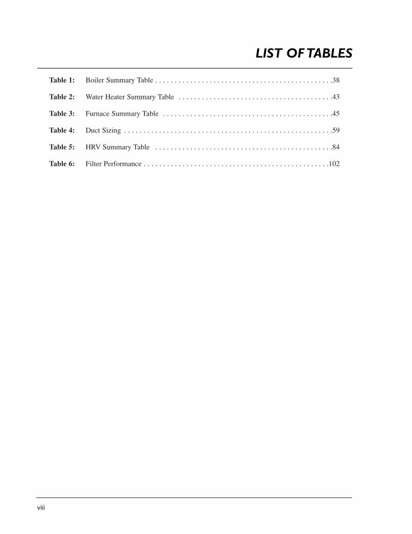
Table 1: Boiler Summary Table . . . . . . . . . . . . . . . . . . . . . . . . . . . . . . . . . . . . . . . . . . . . . .38
Table 2: Water Heater Summary Table . . . . . . . . . . . . . . . . . . . . . . . . . . . . . . . . . . . . . . . .43
Table 3: Furnace Summary Table . . . . . . . . . . . . . . . . . . . . . . . . . . . . . . . . . . . . . . . . . . . .45
Table 4: Duct Sizing . . . . . . . . . . . . . . . . . . . . . . . . . . . . . . . . . . . . . . . . . . . . . . . . . . . . . .59
Table 5: HRV Summary Table . . . . . . . . . . . . . . . . . . . . . . . . . . . . . . . . . . . . . . . . . . . . . .84
Table 6: Filter Performance . . . . . . . . . . . . . . . . . . . . . . . . . . . . . . . . . . . . . . . . . . . . . . . .102
LIST OF TABLES
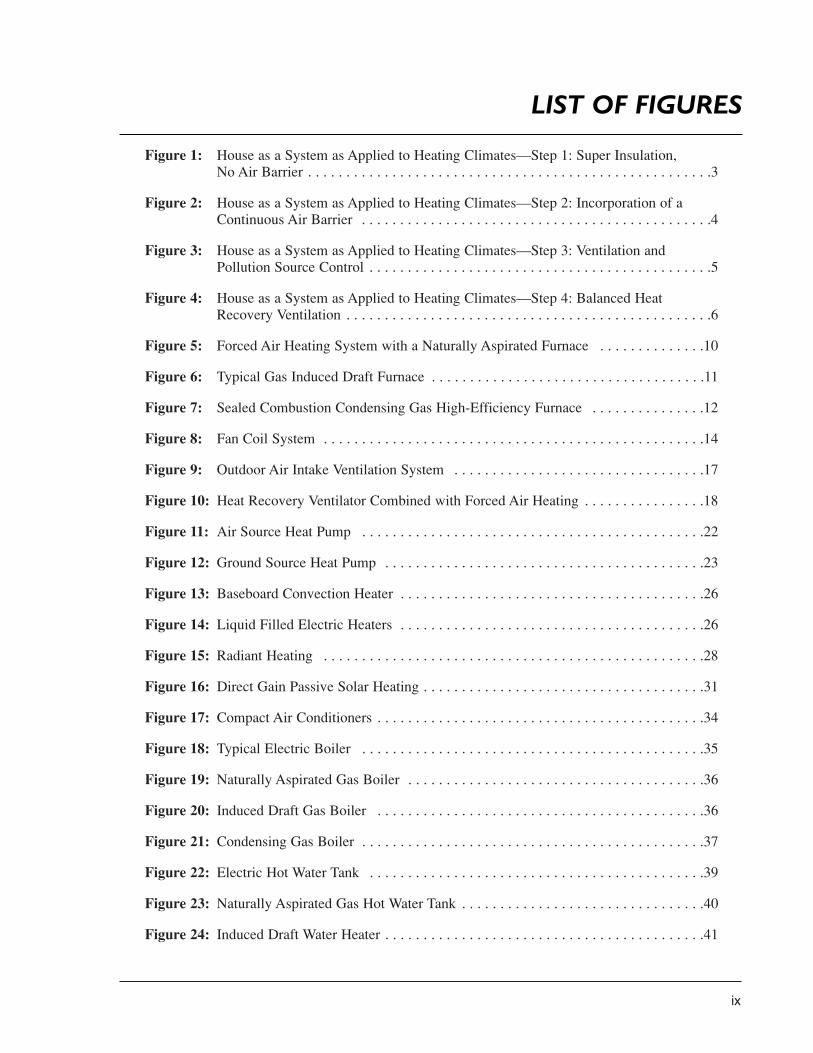
Figure 1: House as a System as Applied to Heating Climates—Step 1: Super Insulation,No Air Barrier . . . . . . . . . . . . . . . . . . . . . . . . . . . . . . . . . . . . . . . . . . . . . . . . . . . . .3
Figure 2: House as a System as Applied to Heating Climates—Step 2: Incorporation of aContinuous Air Barrier . . . . . . . . . . . . . . . . . . . . . . . . . . . . . . . . . . . . . . . . . . . . . .4
Figure 3: House as a System as Applied to Heating Climates—Step 3: Ventilation and Pollution Source Control . . . . . . . . . . . . . . . . . . . . . . . . . . . . . . . . . . . . . . . . . . . . .5
Figure 4: House as a System as Applied to Heating Climates—Step 4: Balanced Heat Recovery Ventilation . . . . . . . . . . . . . . . . . . . . . . . . . . . . . . . . . . . . . . . . . . . . . . . .6
Figure 5: Forced Air Heating System with a Naturally Aspirated Furnace . . . . . . . . . . . . . .10
Figure 6: Typical Gas Induced Draft Furnace . . . . . . . . . . . . . . . . . . . . . . . . . . . . . . . . . . . .11
Figure 7: Sealed Combustion Condensing Gas High-Efficiency Furnace . . . . . . . . . . . . . . .12
Figure 8: Fan Coil System . . . . . . . . . . . . . . . . . . . . . . . . . . . . . . . . . . . . . . . . . . . . . . . . . .14
Figure 9: Outdoor Air Intake Ventilation System . . . . . . . . . . . . . . . . . . . . . . . . . . . . . . . . .17
Figure 10: Heat Recovery Ventilator Combined with Forced Air Heating . . . . . . . . . . . . . . . .18
Figure 11: Air Source Heat Pump . . . . . . . . . . . . . . . . . . . . . . . . . . . . . . . . . . . . . . . . . . . . .22
Figure 12: Ground Source Heat Pump . . . . . . . . . . . . . . . . . . . . . . . . . . . . . . . . . . . . . . . . . .23
Figure 13: Baseboard Convection Heater . . . . . . . . . . . . . . . . . . . . . . . . . . . . . . . . . . . . . . . .26
Figure 14: Liquid Filled Electric Heaters . . . . . . . . . . . . . . . . . . . . . . . . . . . . . . . . . . . . . . . .26
Figure 15: Radiant Heating . . . . . . . . . . . . . . . . . . . . . . . . . . . . . . . . . . . . . . . . . . . . . . . . . .28
Figure 16: Direct Gain Passive Solar Heating . . . . . . . . . . . . . . . . . . . . . . . . . . . . . . . . . . . . .31
Figure 17: Compact Air Conditioners . . . . . . . . . . . . . . . . . . . . . . . . . . . . . . . . . . . . . . . . . . .34
Figure 18: Typical Electric Boiler . . . . . . . . . . . . . . . . . . . . . . . . . . . . . . . . . . . . . . . . . . . . .35
Figure 19: Naturally Aspirated Gas Boiler . . . . . . . . . . . . . . . . . . . . . . . . . . . . . . . . . . . . . . .36
Figure 20: Induced Draft Gas Boiler . . . . . . . . . . . . . . . . . . . . . . . . . . . . . . . . . . . . . . . . . . .36
Figure 21: Condensing Gas Boiler . . . . . . . . . . . . . . . . . . . . . . . . . . . . . . . . . . . . . . . . . . . . .37
Figure 22: Electric Hot Water Tank . . . . . . . . . . . . . . . . . . . . . . . . . . . . . . . . . . . . . . . . . . . .39
Figure 23: Naturally Aspirated Gas Hot Water Tank . . . . . . . . . . . . . . . . . . . . . . . . . . . . . . . .40
Figure 24: Induced Draft Water Heater . . . . . . . . . . . . . . . . . . . . . . . . . . . . . . . . . . . . . . . . . .41
ix
LIST OF FIGURES
x
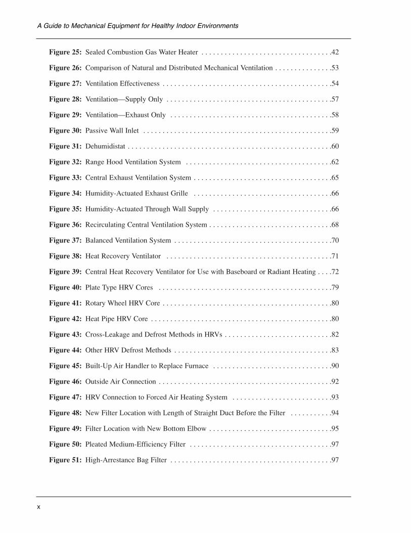
Figure 25: Sealed Combustion Gas Water Heater . . . . . . . . . . . . . . . . . . . . . . . . . . . . . . . . . .42
Figure 26: Comparison of Natural and Distributed Mechanical Ventilation . . . . . . . . . . . . . . .53
Figure 27: Ventilation Effectiveness . . . . . . . . . . . . . . . . . . . . . . . . . . . . . . . . . . . . . . . . . . . .54
Figure 28: Ventilation—Supply Only . . . . . . . . . . . . . . . . . . . . . . . . . . . . . . . . . . . . . . . . . . .57
Figure 29: Ventilation—Exhaust Only . . . . . . . . . . . . . . . . . . . . . . . . . . . . . . . . . . . . . . . . . .58
Figure 30: Passive Wall Inlet . . . . . . . . . . . . . . . . . . . . . . . . . . . . . . . . . . . . . . . . . . . . . . . . .59
Figure 31: Dehumidistat . . . . . . . . . . . . . . . . . . . . . . . . . . . . . . . . . . . . . . . . . . . . . . . . . . . . .60
Figure 32: Range Hood Ventilation System . . . . . . . . . . . . . . . . . . . . . . . . . . . . . . . . . . . . . .62
Figure 33: Central Exhaust Ventilation System . . . . . . . . . . . . . . . . . . . . . . . . . . . . . . . . . . . .65
Figure 34: Humidity-Actuated Exhaust Grille . . . . . . . . . . . . . . . . . . . . . . . . . . . . . . . . . . . .66
Figure 35: Humidity-Actuated Through Wall Supply . . . . . . . . . . . . . . . . . . . . . . . . . . . . . . .66
Figure 36: Recirculating Central Ventilation System . . . . . . . . . . . . . . . . . . . . . . . . . . . . . . . .68
Figure 37: Balanced Ventilation System . . . . . . . . . . . . . . . . . . . . . . . . . . . . . . . . . . . . . . . . .70
Figure 38: Heat Recovery Ventilator . . . . . . . . . . . . . . . . . . . . . . . . . . . . . . . . . . . . . . . . . . .71
Figure 39: Central Heat Recovery Ventilator for Use with Baseboard or Radiant Heating . . . .72
Figure 40: Plate Type HRV Cores . . . . . . . . . . . . . . . . . . . . . . . . . . . . . . . . . . . . . . . . . . . . .79
Figure 41: Rotary Wheel HRV Core . . . . . . . . . . . . . . . . . . . . . . . . . . . . . . . . . . . . . . . . . . . .80
Figure 42: Heat Pipe HRV Core . . . . . . . . . . . . . . . . . . . . . . . . . . . . . . . . . . . . . . . . . . . . . . .80
Figure 43: Cross-Leakage and Defrost Methods in HRVs . . . . . . . . . . . . . . . . . . . . . . . . . . . .82
Figure 44: Other HRV Defrost Methods . . . . . . . . . . . . . . . . . . . . . . . . . . . . . . . . . . . . . . . . .83
Figure 45: Built-Up Air Handler to Replace Furnace . . . . . . . . . . . . . . . . . . . . . . . . . . . . . . .90
Figure 46: Outside Air Connection . . . . . . . . . . . . . . . . . . . . . . . . . . . . . . . . . . . . . . . . . . . . .92
Figure 47: HRV Connection to Forced Air Heating System . . . . . . . . . . . . . . . . . . . . . . . . . .93
Figure 48: New Filter Location with Length of Straight Duct Before the Filter . . . . . . . . . . .94
Figure 49: Filter Location with New Bottom Elbow . . . . . . . . . . . . . . . . . . . . . . . . . . . . . . . .95
Figure 50: Pleated Medium-Efficiency Filter . . . . . . . . . . . . . . . . . . . . . . . . . . . . . . . . . . . . .97
Figure 51: High-Arrestance Bag Filter . . . . . . . . . . . . . . . . . . . . . . . . . . . . . . . . . . . . . . . . . .97
A Guide to Mechanical Equipment for Healthy Indoor Environments
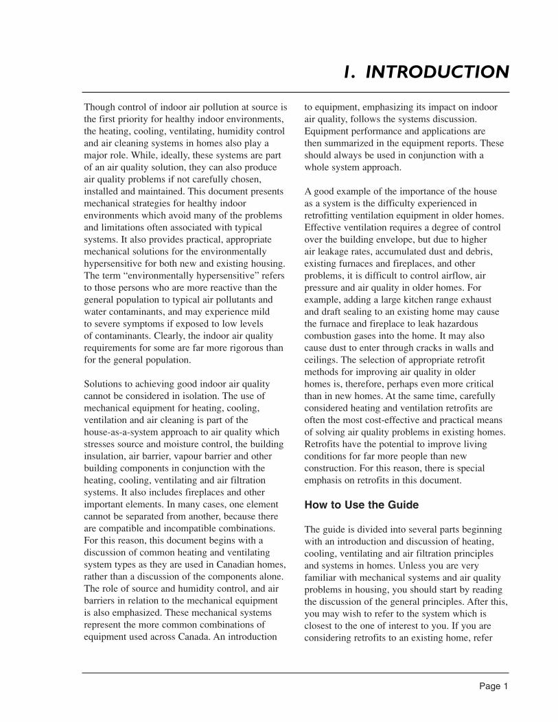
Though control of indoor air pollution at source isthe first priority for healthy indoor environments,the heating, cooling, ventilating, humidity controland air cleaning systems in homes also play amajor role. While, ideally, these systems are partof an air quality solution, they can also produceair quality problems if not carefully chosen,installed and maintained. This document presentsmechanical strategies for healthy indoorenvironments which avoid many of the problemsand limitations often associated with typicalsystems. It also provides practical, appropriatemechanical solutions for the environmentallyhypersensitive for both new and existing housing.The term “environmentally hypersensitive” refersto those persons who are more reactive than thegeneral population to typical air pollutants andwater contaminants, and may experience mild to severe symptoms if exposed to low levels of contaminants. Clearly, the indoor air qualityrequirements for some are far more rigorous thanfor the general population.
Solutions to achieving good indoor air qualitycannot be considered in isolation. The use ofmechanical equipment for heating, cooling,ventilation and air cleaning is part of the house-as-a-system approach to air quality whichstresses source and moisture control, the buildinginsulation, air barrier, vapour barrier and otherbuilding components in conjunction with theheating, cooling, ventilating and air filtrationsystems. It also includes fireplaces and otherimportant elements. In many cases, one elementcannot be separated from another, because thereare compatible and incompatible combinations.For this reason, this document begins with adiscussion of common heating and ventilatingsystem types as they are used in Canadian homes,rather than a discussion of the components alone.The role of source and humidity control, and airbarriers in relation to the mechanical equipment is also emphasized. These mechanical systemsrepresent the more common combinations ofequipment used across Canada. An introduction
to equipment, emphasizing its impact on indoorair quality, follows the systems discussion.Equipment performance and applications are then summarized in the equipment reports. Theseshould always be used in conjunction with awhole system approach.
A good example of the importance of the house as a system is the difficulty experienced inretrofitting ventilation equipment in older homes.Effective ventilation requires a degree of controlover the building envelope, but due to higher air leakage rates, accumulated dust and debris,existing furnaces and fireplaces, and otherproblems, it is difficult to control airflow, airpressure and air quality in older homes. Forexample, adding a large kitchen range exhaustand draft sealing to an existing home may cause the furnace and fireplace to leak hazardouscombustion gases into the home. It may alsocause dust to enter through cracks in walls andceilings. The selection of appropriate retrofitmethods for improving air quality in older homes is, therefore, perhaps even more criticalthan in new homes. At the same time, carefullyconsidered heating and ventilation retrofits areoften the most cost-effective and practical meansof solving air quality problems in existing homes.Retrofits have the potential to improve livingconditions for far more people than newconstruction. For this reason, there is specialemphasis on retrofits in this document.
How to Use the Guide
The guide is divided into several parts beginningwith an introduction and discussion of heating,cooling, ventilating and air filtration principlesand systems in homes. Unless you are veryfamiliar with mechanical systems and air qualityproblems in housing, you should start by readingthe discussion of the general principles. After this,you may wish to refer to the system which isclosest to the one of interest to you. If you areconsidering retrofits to an existing home, refer
Page 1
1. INTRODUCTION
Page 2
to the section dealing with retrofits. If you aredealing with environmental hypersensitivity in the household, you will need to consider thespecial requirements for those circumstances.Discussions pertaining to the environmentallyhypersensitive are in italics.
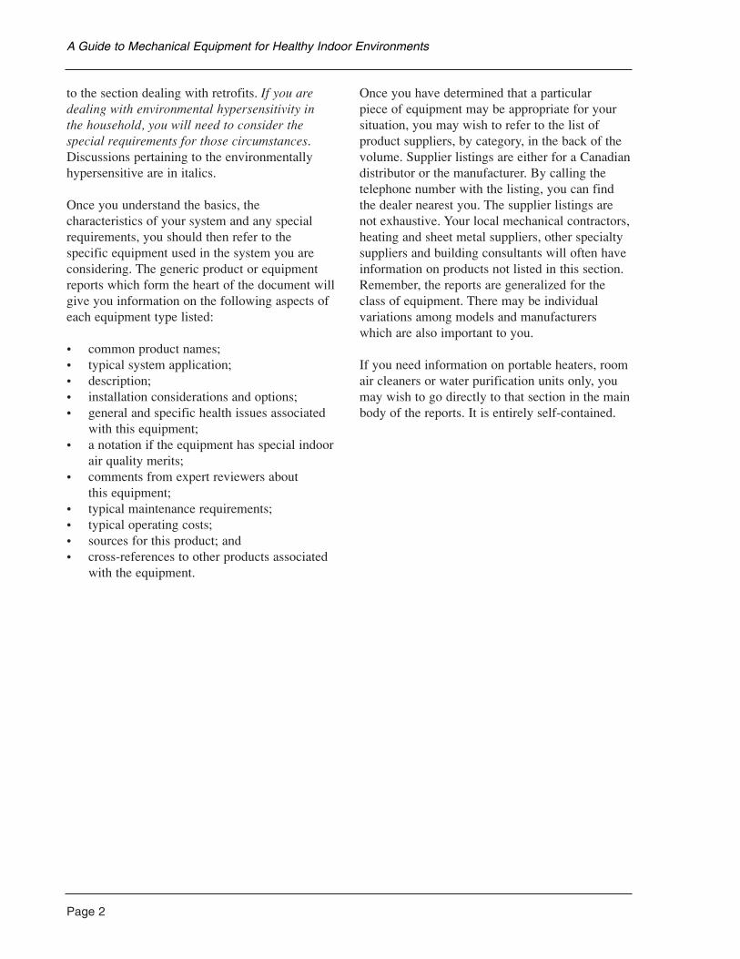
Once you understand the basics, thecharacteristics of your system and any specialrequirements, you should then refer to the specific equipment used in the system you areconsidering. The generic product or equipmentreports which form the heart of the document willgive you information on the following aspects ofeach equipment type listed:
• common product names;• typical system application;• description;• installation considerations and options;• general and specific health issues associated
with this equipment;• a notation if the equipment has special indoor
air quality merits;• comments from expert reviewers about
this equipment;• typical maintenance requirements;• typical operating costs;• sources for this product; and• cross-references to other products associated
with the equipment.
Once you have determined that a particular piece of equipment may be appropriate for yoursituation, you may wish to refer to the list ofproduct suppliers, by category, in the back of thevolume. Supplier listings are either for a Canadiandistributor or the manufacturer. By calling thetelephone number with the listing, you can findthe dealer nearest you. The supplier listings arenot exhaustive. Your local mechanical contractors,heating and sheet metal suppliers, other specialtysuppliers and building consultants will often haveinformation on products not listed in this section.Remember, the reports are generalized for theclass of equipment. There may be individualvariations among models and manufacturerswhich are also important to you.
If you need information on portable heaters, roomair cleaners or water purification units only, youmay wish to go directly to that section in the mainbody of the reports. It is entirely self-contained.
A Guide to Mechanical Equipment for Healthy Indoor Environments
Heat, moisture and air movement in buildings is interrelated—one element cannot be changedwithout affecting the others. The movement isinfluenced by the weather, the occupants, themechanical systems in the house and theconstruction of the building envelope. Theinteractions affect the indoor air quality in thehouse. For this reason, the house as a systemconcept has been developed. When designing and building a home, it is important to understandthese relationships. If this is not done, unexpectedand often negative results can occur. Below areprinciples of the house as a system.
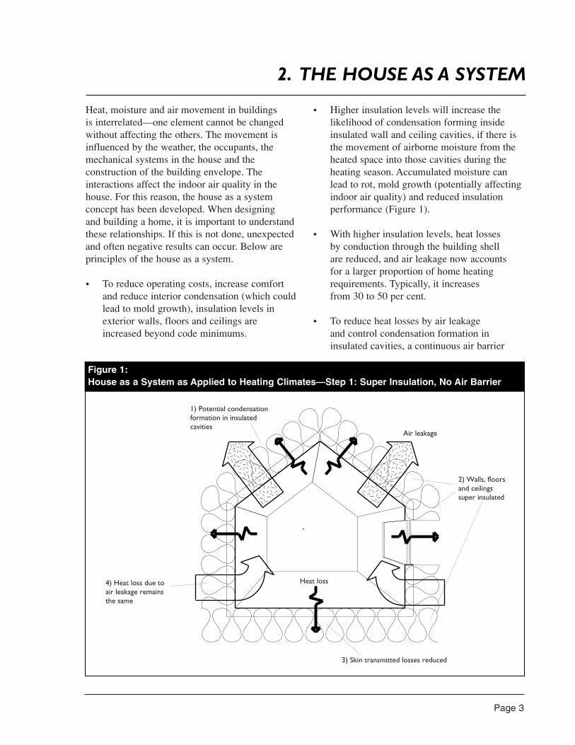
• To reduce operating costs, increase comfortand reduce interior condensation (which couldlead to mold growth), insulation levels inexterior walls, floors and ceilings areincreased beyond code minimums.
• Higher insulation levels will increase thelikelihood of condensation forming insideinsulated wall and ceiling cavities, if there isthe movement of airborne moisture from theheated space into those cavities during theheating season. Accumulated moisture canlead to rot, mold growth (potentially affectingindoor air quality) and reduced insulationperformance (Figure 1).
• With higher insulation levels, heat losses by conduction through the building shell are reduced, and air leakage now accounts for a larger proportion of home heatingrequirements. Typically, it increases from 30 to 50 per cent.
• To reduce heat losses by air leakage and control condensation formation ininsulated cavities, a continuous air barrier
Page 3
2. THE HOUSE AS A SYSTEM
2) Walls, floorsand ceilingssuper insulated
3) Skin transmitted losses reduced
4) Heat loss due toair leakage remainsthe same
1) Potential condensationformation in insulatedcavities
Air leakage
Heat loss
Figure 1:House as a System as Applied to Heating Climates—Step 1: Super Insulation, No Air Barrier
Page 4
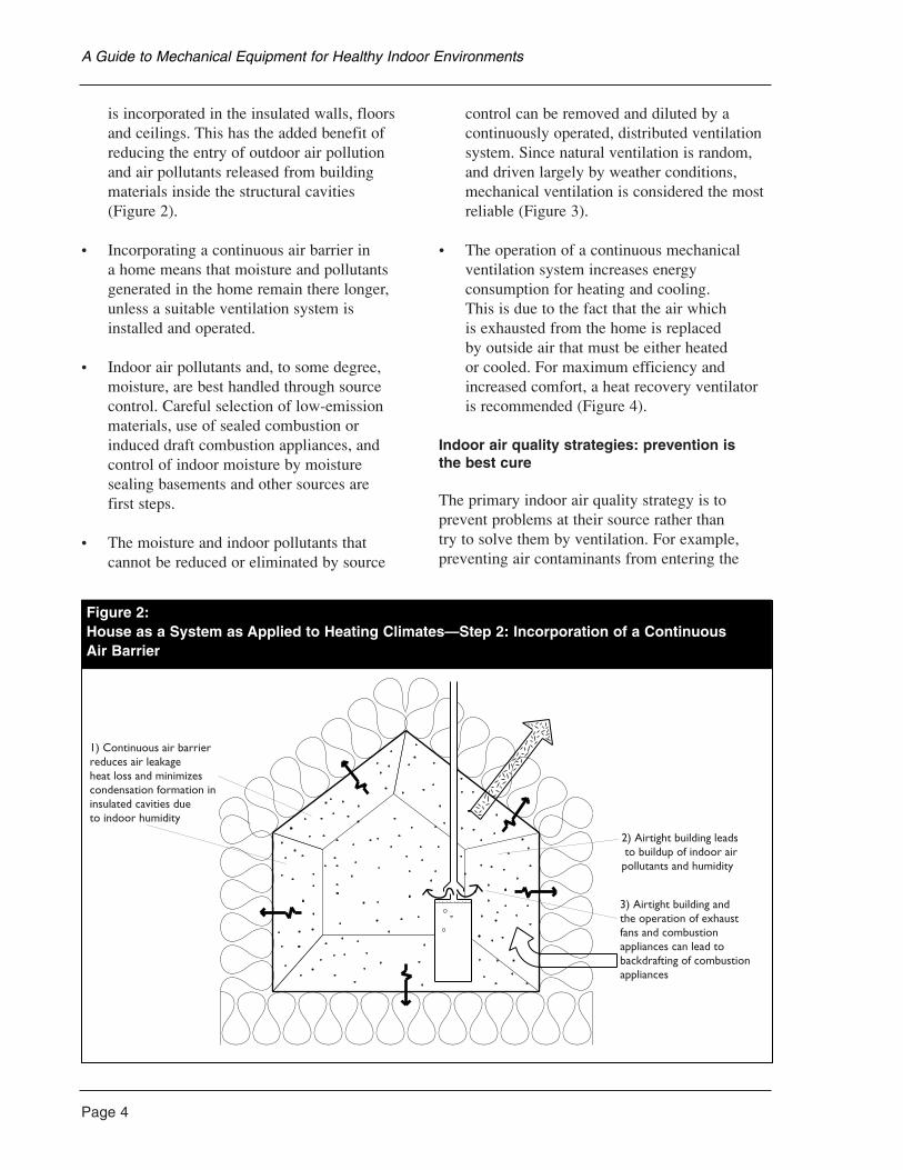
is incorporated in the insulated walls, floorsand ceilings. This has the added benefit ofreducing the entry of outdoor air pollutionand air pollutants released from buildingmaterials inside the structural cavities (Figure 2).
• Incorporating a continuous air barrier in a home means that moisture and pollutantsgenerated in the home remain there longer,unless a suitable ventilation system isinstalled and operated.
• Indoor air pollutants and, to some degree,moisture, are best handled through sourcecontrol. Careful selection of low-emissionmaterials, use of sealed combustion orinduced draft combustion appliances, andcontrol of indoor moisture by moisturesealing basements and other sources are first steps.
• The moisture and indoor pollutants thatcannot be reduced or eliminated by source
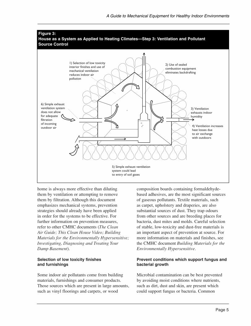
control can be removed and diluted by acontinuously operated, distributed ventilationsystem. Since natural ventilation is random,and driven largely by weather conditions,mechanical ventilation is considered the mostreliable (Figure 3).
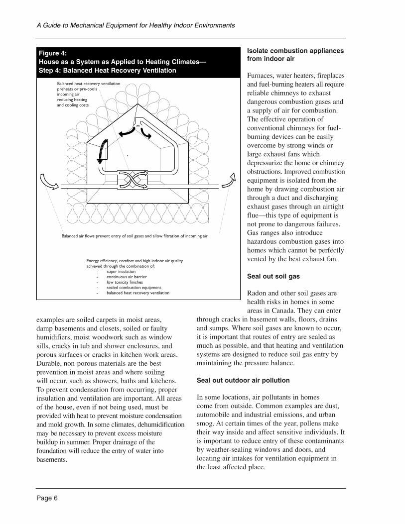
• The operation of a continuous mechanicalventilation system increases energyconsumption for heating and cooling. This is due to the fact that the air which is exhausted from the home is replaced by outside air that must be either heated or cooled. For maximum efficiency andincreased comfort, a heat recovery ventilatoris recommended (Figure 4).
Indoor air quality strategies: prevention is the best cure
The primary indoor air quality strategy is toprevent problems at their source rather than try to solve them by ventilation. For example,preventing air contaminants from entering the
A Guide to Mechanical Equipment for Healthy Indoor Environments
1) Continuous air barrier reduces air leakageheat loss and minimizes condensation formation ininsulated cavities dueto indoor humidity
2) Airtight building leads to buildup of indoor airpollutants and humidity
3) Airtight building andthe operation of exhaustfans and combustionappliances can lead tobackdrafting of combustionappliances
Figure 2:House as a System as Applied to Heating Climates—Step 2: Incorporation of a Continuous Air Barrier
home is always more effective than diluting them by ventilation or attempting to remove them by filtration. Although this documentemphasizes mechanical systems, preventionstrategies should already have been applied in order for the systems to be effective. Forfurther information on prevention measures, refer to other CMHC documents (The Clean Air Guide; This Clean House Video; BuildingMaterials for the Environmentally Hypersensitive;Investigating, Diagnosing and Treating YourDamp Basement).
Selection of low toxicity finishes and furnishings
Some indoor air pollutants come from buildingmaterials, furnishings and consumer products.Those sources which are present in large amounts,such as vinyl floorings and carpets, or wood
composition boards containing formaldehyde-based adhesives, are the most significant sourcesof gaseous pollutants. Textile materials, such as carpet, upholstery and draperies, are alsosubstantial sources of dust. They trap odours from other sources and are breeding places forbacteria, dust mites and molds. Careful selectionof stable, low-toxicity and dust-free materials isan important aspect of prevention at source. Formore information on materials and finishes, seethe CMHC document Building Materials for theEnvironmentally Hypersensitive.
Prevent conditions which support fungus andbacterial growth
Microbial contamination can be best prevented by avoiding moist conditions where nutrients,such as dirt, dust and skin, are present whichcould support fungus or bacteria. Common
Page 5
A Guide to Mechanical Equipment for Healthy Indoor Environments
1) Selection of low toxicityinterior finishes and use ofmechanical ventilationreduces indoor air pollution
2) Use of sealedcombustion equipmenteliminates backdrafting
3) Ventilationexhausts indoorhumidity
4) Ventilation increasesheat losses dueto air exchangewith outdoors
5) Simple exhaust ventilationsystem could leadto entry of soil gases
6) Simple exhaustventilation systemdoes not allowfor adequatefiltrationof incomingoutdoor air
Figure 3:House as a System as Applied to Heating Climates—Step 3: Ventilation and Pollutant Source Control
Page 6
examples are soiled carpets in moist areas, damp basements and closets, soiled or faultyhumidifiers, moist woodwork such as windowsills, cracks in tub and shower enclosures, andporous surfaces or cracks in kitchen work areas.Durable, non-porous materials are the bestprevention in moist areas and where soiling will occur, such as showers, baths and kitchens.To prevent condensation from occurring, properinsulation and ventilation are important. All areasof the house, even if not being used, must beprovided with heat to prevent moisture condensationand mold growth. In some climates, dehumidificationmay be necessary to prevent excess moisturebuildup in summer. Proper drainage of thefoundation will reduce the entry of water intobasements.
Isolate combustion appliancesfrom indoor air
Furnaces, water heaters, fireplacesand fuel-burning heaters all requirereliable chimneys to exhaustdangerous combustion gases anda supply of air for combustion.The effective operation ofconventional chimneys for fuel-burning devices can be easilyovercome by strong winds orlarge exhaust fans whichdepressurize the home or chimneyobstructions. Improved combustionequipment is isolated from thehome by drawing combustion airthrough a duct and dischargingexhaust gases through an airtightflue—this type of equipment isnot prone to dangerous failures.Gas ranges also introducehazardous combustion gases intohomes which cannot be perfectlyvented by the best exhaust fan.
Seal out soil gas
Radon and other soil gases arehealth risks in homes in someareas in Canada. They can enter
through cracks in basement walls, floors, drainsand sumps. Where soil gases are known to occur,it is important that routes of entry are sealed asmuch as possible, and that heating and ventilationsystems are designed to reduce soil gas entry bymaintaining the pressure balance.
Seal out outdoor air pollution
In some locations, air pollutants in homes come from outside. Common examples are dust,automobile and industrial emissions, and urbansmog. At certain times of the year, pollens maketheir way inside and affect sensitive individuals. Itis important to reduce entry of these contaminantsby weather-sealing windows and doors, andlocating air intakes for ventilation equipment inthe least affected place.
A Guide to Mechanical Equipment for Healthy Indoor Environments
Balanced heat recovery ventilationpreheats or pre-coolsincoming airreducing heatingand cooling costs
Balanced air flows prevent entry of soil gases and allow filtration of incoming air
Energy efficiency, comfort and high indoor air qualityachieved through the combination of:
- super insulation- continuous air barrier- low toxicity finishes- sealed combustion equipment- balanced heat recovery ventilation
Figure 4:House as a System as Applied to Heating Climates—Step 4: Balanced Heat Recovery Ventilation
Seal out gases and dust emitted by building materials
For pollutant sources such as insulation in wallsand ceilings which cannot be avoided, the bestprevention is to seal them in place. The use of a continuous air and vapour barrier for wall andceiling construction is an example of sealing out a source of dusts and gases.
Important lifestyle choices
Smokers in the household, pets, hobby activities,storage of hazardous materials, and cleaning andmaintenance methods are also very importantsources of indoor air pollutants. These are largelylifestyle choices made by the occupants whichhave a major negative impact on the indoor air quality.
Page 7
A Guide to Mechanical Equipment for Healthy Indoor Environments
Page 8
Energy Sources
Natural gas
Natural gas is the preferred heating fuel in many Canadian regions where it is available. It is a low-cost and reliable fuel which is primarilycomposed of methane with small amounts ofother gases. A potent odourant is added to makegas leaks detectable. Many environmentallyhypersensitive persons must avoid gasinstallations in the home due to the risk of small leaks and flue gas spillage. If gas is used, a gas-fired boiler should be chosen. These boilersshould be either a sealed-combustion type orlocated in a separate boiler room, preferablyaccessed from the outside.
Open gas ranges, gas space heaters and gasclothes dryers are definitely not recommended for the hypersensitive.
Natural gas is an odourless fuel; however, theodourant added is made from methyl, ethyl andbutyl mercaptan compounds containing sulphur.These are very potent irritants and exposure totiny amounts may cause severe reactions in the hypersensitive.
Propane
Propane is commonly used as a heating fuel inrural locations where natural gas is unavailable. It is primarily composed of propane and butanegases with the addition of the same odourant usedin natural gas. The advantage of propane is that it can be easily liquefied for transportation andstorage, while natural gas cannot. Generally, mostnatural gas-burning appliances can be fuelled bypropane with minor modifications, so the samesystems and equipment are applicable.
Though propane is chemically quite different from natural gas, the concerns with propane and natural gas are every similar. The explosionrisk and irritant nature of the odourants are themajor concerns.
Fuel oil
Home heating oil is a traditional heating fuel inmany parts of Canada, though it is rapidly beingreplaced by natural gas as it becomes available. It is composed of light petroleum distillatescontaining small amounts of aromatic compoundsand sulphur. Because supplies are perceived to belimited, there has been a national program toreplace heating oil.
Oil has a strong odour which many people findobjectionable. Delivering and handling oil cancause small spills. Oil burners can leak, leavingoil-saturated floors in basements. The residualodour from oil leaks can last several months oryears. It burns with a great deal more residue thanother fuels. Oil burning typically produces somesmoke and soot, as well as sulphur oxides.
Electricity
Using electricity directly as a heat source is not preferred from an environmental or a utilitymanagement standpoint in many regions ofCanada. This is because electricity is a high-quality form of energy that can do many usefulthings. Heating is a low-quality use. If theelectricity source is a coal-fired or nuclear plant, less than one third of the fuel used isconverted to useful electricity. However, in British Columbia and Québec, where most of the electricity is hydro-electric, there is a gooddeal of electric heating done. Generally, a heatpump is a more appropriate way to use electricityfor heating because it is two to three times moreeffective than electric resistance heaters.
Electricity is a clean fuel from the standpoint of occupant health because it requires no fuelhandling and no on-site combustion. However, in regions with thermal generating plants, it is a serious regional pollution concern. Concernsabout exposure to low-frequency electromagneticfields from electrical appliances in the home arealso emerging, but this area is in its infancy andpoorly understood.
3. HEATING AND COOLING
Wood
A substantial amount of wood heating is done in Canada, particularly in small towns and ruralareas. Though wood is a renewable fuel withminimal environmental impact, many woodburningappliances are very inefficient and producesubstantial air pollution. The problem is so seriousin some colder regions that restrictions on burningare applied.
Burning wood in all but the most efficientappliances produces smoke, soot, ash andaromatic hydrocarbons. Most are serious local air pollutants and some are carcinogenic. In areas with a great deal of woodburning, the healtheffects on the population are a serious concern.Many houses for the hypersensitive do not includewoodburning appliances. If they are included,they usually have tight chimneys and meet low-emission wood heater listing requirements. To reduce flue emissions, some have catalyticconverters and draft fans which require regularmaintenance. Conventional open fireplaces of anykind are not recommended due to the difficulty in preventing entry of flue gases and soot into the home.
Woodburners meeting CSA B415.1-M92“Performance Testing of Stoves, Inserts and Low to Medium Burn Rate Factory BuiltFireplaces” or the United States EnvironmentalProtection Agency (EPA) woodburning appliancestandards (1990), CFR Part 60, are lower-emission units if operated correctly.
Furnace Types Based on Fuel
Gas furnaces
This classification of furnaces also applies toboilers and domestic hot water tanks.
Naturally aspirated
Naturally aspirated gas or propane furnaces relyon the natural buoyancy of the heated flue gasesfor venting. They draw air from the house forcombustion. Dilution air is brought in through
a draft hood, primarily to isolate the burner fromchanging outside pressure conditions at the top ofthe chimney. Their efficiencies are typicallyaround 65 per cent.
Because the burner is open to the home interior, these units are prone to flue gas spillage (backdrafting) when other combustionappliances and exhaust fans are operating.Naturally aspirated gas furnaces also have a pilot light which is a source of unburned andcombustion gases.
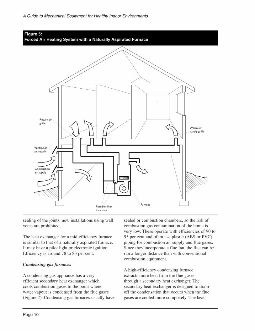
The primary heat exchanger is usually a set of tubes or channels fabricated from welded steel. The combustion process occurs inside thechannels and the air from the blower is passeddirectly over the outside of them (Figure 5). Theprimary heat exchanger must operate at hightemperatures to prevent condensation fromaccumulating on the metal parts and to boost flue gases up the chimney.
Mid-efficiency furnace (induced or forced draft)
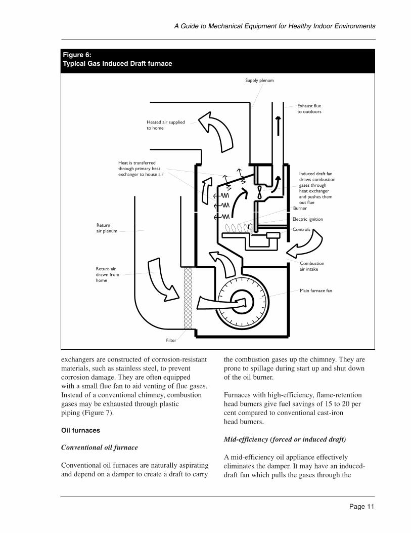
The mid-efficiency furnace usually has aninduced-draft fan located in the exhaust flue to control the flow of gases through the furnace(Figure 6). Combustion air is drawn from thehome and the flue fan forces the combustiongases out through the flue. The furnace resistsflue gas spillage (backdrafting) more effectivelythan naturally aspirated units, but does noteliminate backdrafting. Forced-draft systems with power burners, commonly used in boilers,perform similarly.
No draft hood is needed. Due to the lack ofdilution air, the amount of gas flowing throughthe venting system is less. The reduced flow andlower flue-gas temperatures can cause the fluegases to condense in the furnace or ventingsystem. Condensation is reduced by using adouble-walled connector and chimney vent, both sized to the reduced gas flow.
Instead of venting through the roof, the flue isoften vented through the wall. Due to majorproblems associated with the plastic vent and
Page 9
A Guide to Mechanical Equipment for Healthy Indoor Environments
Page 10
sealing of the joints, new installations using wallvents are prohibited.
The heat exchanger for a mid-efficiency furnaceis similar to that of a naturally aspirated furnace.It may have a pilot light or electronic ignition.Efficiency is around 78 to 83 per cent.
Condensing gas furnaces
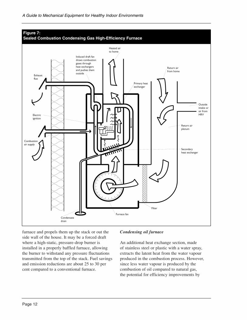
A condensing gas appliance has a very efficient secondary heat exchanger which cools combustion gases to the point where water vapour is condensed from the flue gases(Figure 7). Condensing gas furnaces usually have
sealed or combustion chambers, so the risk ofcombustion gas contamination of the home isvery low. These operate with efficiencies of 90 to95 per cent and often use plastic (ABS or PVC)piping for combustion air supply and flue gases.Since they incorporate a flue fan, the flue can berun a longer distance than with conventionalcombustion equipment.
A high-efficiency condensing furnace extracts more heat from the flue gases through a secondary heat exchanger. Thesecondary heat exchanger is designed to drain off the condensation that occurs when the fluegases are cooled more completely. The heat
A Guide to Mechanical Equipment for Healthy Indoor Environments
Forced Air Heating System with a Naturally Aspirated Furnace
Return airgrille
Ventilationair supply
Combustionair supply
Possible filterlocations
Furnace
Warm airsupply grille
Figure 5:Forced Air Heating System with a Naturally Aspirated Furnace
exchangers are constructed of corrosion-resistantmaterials, such as stainless steel, to preventcorrosion damage. They are often equipped with a small flue fan to aid venting of flue gases.Instead of a conventional chimney, combustiongases may be exhausted through plastic piping (Figure 7).
Oil furnaces
Conventional oil furnace
Conventional oil furnaces are naturally aspiratingand depend on a damper to create a draft to carry
the combustion gases up the chimney. They areprone to spillage during start up and shut down of the oil burner.
Furnaces with high-efficiency, flame-retentionhead burners give fuel savings of 15 to 20 percent compared to conventional cast-iron head burners.
Mid-efficiency (forced or induced draft)
A mid-efficiency oil appliance effectivelyeliminates the damper. It may have an induced-draft fan which pulls the gases through the
Page 11
A Guide to Mechanical Equipment for Healthy Indoor Environments
Supply plenum
Exhaust flueto outdoors
Induced draft fandraws combustiongases throughheat exchangerand pushes themout flue
Burner
Electric ignition
Controls
Combustionair intake
Main furnace fan
Filter
Return airdrawn fromhome
Returnair plenum
Heat is transferredthrough primary heatexchanger to house air
Heated air suppliedto home
Figure 6:Typical Gas Induced Draft furnace
Page 12
furnace and propels them up the stack or out theside wall of the house. It may be a forced draftwhere a high-static, pressure-drop burner isinstalled in a properly baffled furnace, allowingthe burner to withstand any pressure fluctuationstransmitted from the top of the stack. Fuel savingsand emission reductions are about 25 to 30 percent compared to a conventional furnace.
Condensing oil furnace
An additional heat exchange section, made of stainless steel or plastic with a water spray,extracts the latent heat from the water vapourproduced in the combustion process. However,since less water vapour is produced by thecombustion of oil compared to natural gas, the potential for efficiency improvements by
A Guide to Mechanical Equipment for Healthy Indoor Environments
Heated airto home
Return airfrom home
Primary heatexchanger
Outsideintake orair fromHRV
Return airplenum
Secondaryheat exchanger
Filter
Furnace fanCondensatedrain
Combustionair supply
Electricignition
Exhaustflue
Induced draft fandraws combustiongases throughheat exchangersand pushes themoutside
Figure 7:Sealed Combustion Condensing Gas High-Efficiency Furnace
condensing the flue gas from oil is much lower.The condensate is also very corrosive, and sootcan be deposited on the heat exchange surface.Condensing oil furnaces have effiencies that rangefrom being somewhat less efficient than the bettermid-efficiency types to eight per cent higher.
Due to the higher costs and potential corrosion ofcondensing oil units, mid-efficiency oil furnacesare preferred. Oil-condensing units are notrecommended at present.
Electric furnaces
Electric forced air furnaces use heating coils madeof resistance wires similar to toaster or electricrange elements. Electric hot water tanks arewidely used. Electric boilers are available.
Forced Air Systems
A forced air system is a heating or cooling plant which recirculates house air. The basiccomponents are a fan, a burner or other heatsource, a heat exchanger, supply ducts, grilles ordiffusers, a return air path and controls. Thecommon optional components are a cooling coil,air filtration, humidification, an outside air supplyand zone controls to allow heating or cooling ofindividual parts of the house. Though a forced airsystem can be an appropriate choice for goodindoor air quality, not all heating plants are alike(Figure 5).
Heating plant
Heating plants are fuelled by natural gas, propane,fuel oil, electric or wood heat. In some areas,dual-fuel systems such as oil and electricity areinstalled. Due to its moderate installation cost and simplicity, a conventional gas-fired forced air furnace is the most common heating plant inCanadian housing where natural gas is available(Figure 6). However, it is not the preferred unitfor indoor air quality since it may releasecombustion products into the house.
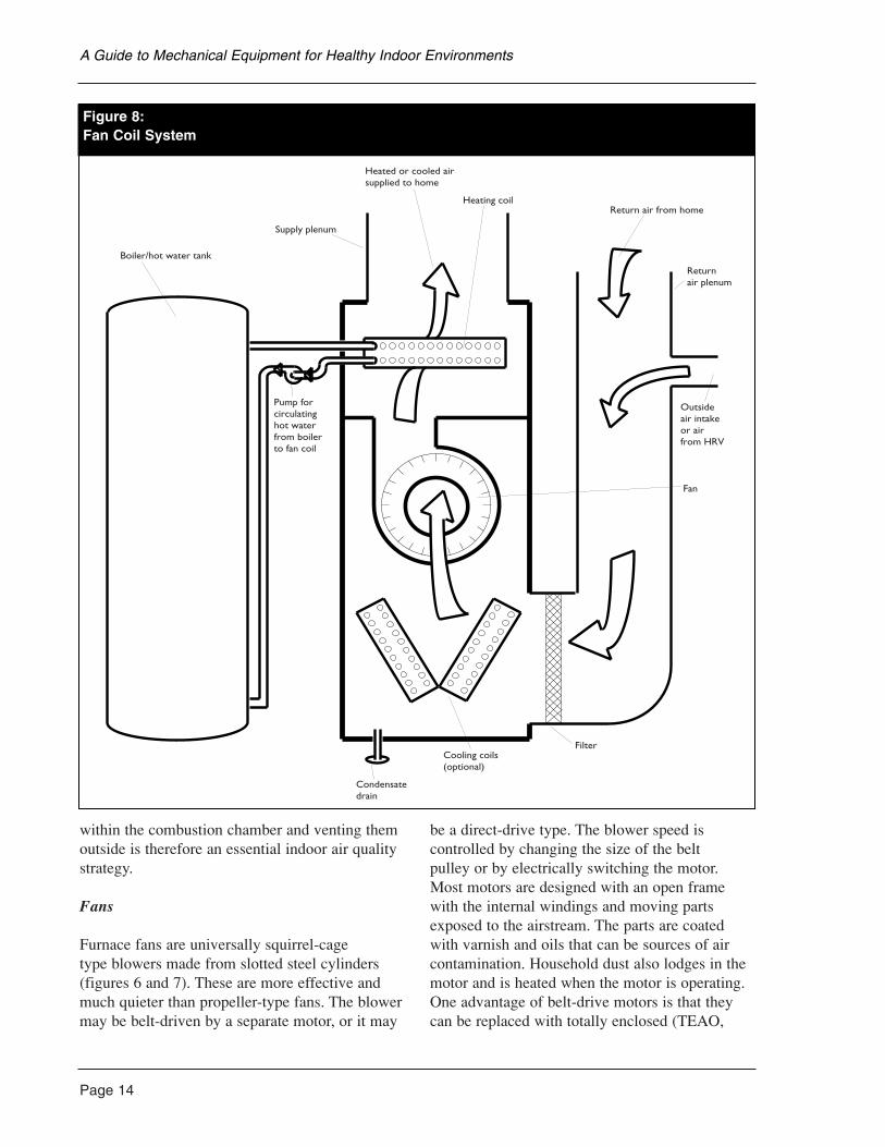
An alternative type of heating plant contains aboiler and an air handler called a fan coil. The
source of heating or cooling is a boiler, hot water heater, heat pump or an energy recovery orstorage unit. A fan coil has significant advantagesfor indoor air quality because the heat exchangetemperature is lower and any fuel burner involvedcan be isolated from the home. See the fan coilsection for more details (Figure 8).
Cooling plant
Virtually all residential cooling plants are electric motor-driven refrigeration units. Themajor component, incorporating a compressor,condenser and cooling fan, is generally locatedoutdoors in a weatherproof cabinet. A refrigerant,circulated by the compressor, extracts heat fromhouse air through a coil mounted in the airstreamand discharges it outdoors through the outsidecondensing coil. Because cooling of air alsoreduces its capacity to hold moisture, a coolingunit will also dehumidify indoor air. Thismoisture will accumulate as condensate on the expansion coils in the fan coil and must becollected and drained away. Trapped moisture incooling equipment is a serious health risk since itacts as a growth medium for bacteria and fungi.
Heat pumps are primarily designed for heatinghomes but may also function as cooling plantswhen their operation is reversed. Heat is extractedfrom outdoor air or groundwater and dischargedinto the house air through a coil. Heat pumps can also be designed to have their cycles reverseautomatically for summer cooling. See the heatpump/air conditioner section for more details.
Forced air furnace components
Furnaces
Furnaces can be either fuel burning (combustiontype) or electric. See the previous section for adiscussion of the different furnaces.
Combustion equipment in the home produceshazardous combustion gases, gaseous residuesfrom unburned fuel and, in some cases, soot. All are serious indoor air pollutants if allowed to enter the home. Reliably containing these
Page 13
A Guide to Mechanical Equipment for Healthy Indoor Environments
Page 14
within the combustion chamber and venting themoutside is therefore an essential indoor air qualitystrategy.
Fans
Furnace fans are universally squirrel-cage type blowers made from slotted steel cylinders(figures 6 and 7). These are more effective andmuch quieter than propeller-type fans. The blowermay be belt-driven by a separate motor, or it may
be a direct-drive type. The blower speed iscontrolled by changing the size of the belt pulley or by electrically switching the motor.Most motors are designed with an open framewith the internal windings and moving partsexposed to the airstream. The parts are coatedwith varnish and oils that can be sources of aircontamination. Household dust also lodges in themotor and is heated when the motor is operating.One advantage of belt-drive motors is that theycan be replaced with totally enclosed (TEAO,
A Guide to Mechanical Equipment for Healthy Indoor Environments
Boiler/hot water tank
Supply plenum
Heated or cooled air supplied to home
Heating coilReturn air from home
Returnair plenum
Outsideair intakeor airfrom HRV
Fan
FilterCooling coils(optional)
Condensatedrain
Pump forcirculatinghot waterfrom boilerto fan coil
Figure 8:Fan Coil System
TENV or TEFC) motors. Belt drives areintrinsically more noisy. These motors havewindings and internal parts that are completelysealed from the airstream thereby reducing air pollutants.
The supply-air fan in the traditional natural-draft, forced air furnace is operated by a fancontrol which starts the fan only after the heatexchanger has warmed up. The fan is also stoppedbefore it completely cools down. This ensures thatthe air delivered to the house is usually warmerthan body temperature, and will rarely causediscomfort complaints, even when the airstreamblows directly on people. This traditional fancontrol method is less common in recentlyconstructed houses because the furnace usuallyhas a continuously operating fan. In thesesystems, the fan is operated at a lower speed toimprove heat and air distribution and to providebetter ventilation and air filtration.
When a boiler and fan coil heating system are used, the delivered air temperature maysometimes be less than skin temperature andcause comfort complaints. This may also occurwith a burner-type furnace when cold outdoor air is mixed with recirculated air when the fan is operating but the burner is off. Given these conditions, which commonly occur incontemporary forced air designs, the preferredapproach is to locate the warm-air supply registersso they do not flow directly onto room occupants.
Several sophisticated furnaces and fan coil units now use electronically controlledpermanent magnet motors. These are often calledelectronically commutated motors and are capableof an almost infinite speed range variation whilemaintaining high efficiency. Use of these motorsallows optimum control over heating and coolingefficiency, comfort levels, noise and fan energyconsumption when used with the appropriatecontrol systems.
Filters
Furnace filters are normally located where the return air enters into the furnace cabinet
(Figure 6). The filters normally supplied with the furnace are primarily intended to reduce the accumulation of dust on the heat exchanger,blower motor, fan wheel and supply ducts. Manytypes of improved filters are available which canbe added to, or used in place of, standard furnacefilters. These remove fine dust and odours.
Supply and return ductwork
Air from the furnace is delivered to the rooms ofthe house through supply ductwork. While supplyductwork in most Canadian homes is constructedof galvanized steel sheet, any durable materialthat is non-combustible and corrosion-resistantsuch as aluminum, copper, clay or concrete maybe used. Ducts should be made of non-absorbent,durable materials since dust collection, mold build up or odour absorption are less likely. Theauthoritative source for the design and layout ofconventional heating and cooling duct systems isthe HRAI Residential Air System Design Manual.The design of the supply ductwork can have astrong influence on the balance of air supplybetween rooms. The system must be designed so heat flow to the rooms balances heat lossesfrom the rooms and, if the same system is usedfor cooling, it will often be necessary to adjust the airflow rates for cooling operation. Ductworkshould have balancing dampers at each split orduct take-off to allow proper balancing.Furthermore, the ducts should be accessible for cleaning and designed to minimize thetrapping of dust and debris.
Air is returned to the furnace via a return air pathor return ductwork. Though some furnace unitsare located in a closet and require minimal returnair ductwork, most conventional designs requireductwork across the house and from upper floorswhere the air is returned through grilles. In somenew systems, the return grilles are located nearthe ceiling, as high as possible in the house, toimprove heat distribution and comfort.
The construction of the return ductwork issignificantly different from the supply airductwork because air is handled at a lowertemperature and fewer return points are
Page 15
A Guide to Mechanical Equipment for Healthy Indoor Environments
Page 16
required. In many homes, interior wall and floorframing cavities have been blocked off with woodand sheet metal and are used as returns. In thesesituations, the wood studs or joists, gypsumwallboard or wood sub-floor form the walls of the duct. Return duct design is very important for indoor air quality, not only for comfort andefficiency, but because accumulated dust anddebris in ducts are an important source of indoorair contamination. These ducts also tend to drawin contaminated air from crawl spaces andinsulation cavities. In some carefully designedhouses using forced air systems, all return-airducts are lined with sheet metal and sealed sothey tend to accumulate less debris and are more easily cleaned.
Grilles, registers, diffusers
A grille is a slotted plate with no adjustmentwhich is most often used for return air. A registeris a plate with an adjusting damper which helpscontrol air volume and sometimes, air direction.Registers are commonly used for heated supplyair in floors and sometimes for wall and ceilingapplications. A diffuser is a round or rectangularfixture designed to project air into the room in a specific pattern. Diffusers are most commonlylocated in ceilings and walls, and used forventilation or cooling supply air. The location of registers and diffusers must encourage a goodair mixing pattern in the room while providingcomfort. This is usually achieved by locating the air-supply point as far away from the air-exit point as possible, and ensuring that air is not blown directly onto people.
Humidification
Humidification is often important in colderregions where winter dryness is a problem. Atraditional method for forced air systems is to usean add-on device, a humidifier which passes partof the airstream through an absorbent materialthat is moistened from a water reservoir. Some are simply switched on when needed, though a humidity control can also be used to providehumidification automatically.
The traditional types of residential humidifiers are prone to biological growth because they usetap water at room temperature and accumulatedust and debris which support bacteria and fungi. If humidification of a forced air system is necessary for health reasons in a very dryclimate, then careful, regular cleaning andmaintenance are essential.
Heating and cooling controls
The traditional basic control in a forced airheating system is a single, low voltage (24 volt)thermostat, located centrally in the house. Moresophisticated thermostats are now available which control both cooling and heating functionsseparately and allow for control of the fan,independently of the heating or cooling function,while saving energy and money. Multi-stagethermostats are also available for some heatingplants which can provide partial heating orcooling when the air temperature is fairly close to the thermostat setting. These improve thecomfort and efficiency of operation.
Programmable thermostats are also now quitecommon in residential applications. These allow the temperature to be preset according to a 24-hour or seven-day program. This canprovide energy savings (typically 10 to 15 percent) through automatic setbacks during sleepinghours or when the house is unoccupied, as well asa morning warm-up period before sleepers rise.
Zoned control systems are also available forresidential forced air systems, though they areuncommon. These provide automatic control of one or more rooms separately, using localthermostats and motorized dampers to direct air to the zones. Control systems can result inimproved control for some home designs, as wellas reduced equipment capacity, particularly for acooling plant. However, the ability of the systemto fully recirculate air throughout the house maybe reduced when they are used.
A Guide to Mechanical Equipment for Healthy Indoor Environments
Integrating ventilation with a forced air system
Forced air systems are easily adapted to provideventilation or assist in ventilating. There aregenerally two ways of doing this: add an outdoorair intake or integrate a heat recovery ventilatorwith the system.
Outdoor ventilation air intake
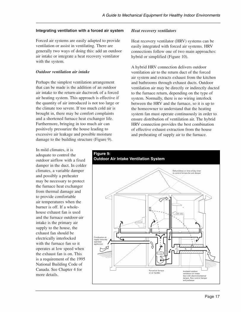
Perhaps the simplest ventilation arrangement that can be made is the addition of an outdoor air intake to the return-air ductwork of a forcedair heating system. This approach is effective ifthe quantity of air introduced is not too large orthe climate too severe. If too much cold air isbrought in, there may be comfort complaints and a shortened furnace heat exchanger life.Furthermore, bringing in too much air canpositively pressurize the house leading toexcessive air leakage and possible moisturedamage to the building structure (Figure 9).
In mild climates, it isadequate to control theoutdoor airflow with a fixeddamper in the duct. In colderclimates, a variable damperand possibly a preheater may be necessary to protectthe furnace heat exchangerfrom thermal damage and to provide comfortable air temperatures when theburner is off. If a whole-house exhaust fan is used and the furnace outdoor-airintake is the primary airsupply to the house, theexhaust fan should beelectrically interlocked with the furnace fan so itoperates at low speed whenthe exhaust fan is on. This is a requirement of the 1995National Building Code ofCanada. See Chapter 4 formore details.
Heat recovery ventilators
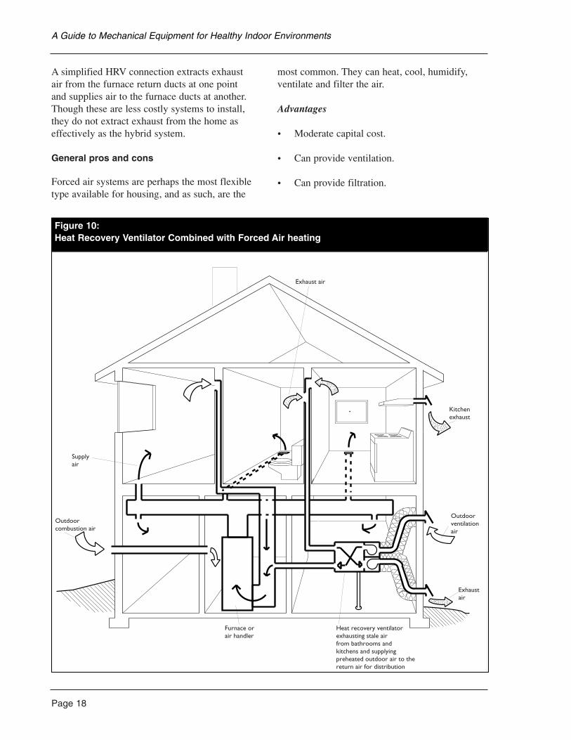
Heat recovery ventilator (HRV) systems can beeasily integrated with forced air systems. HRVconnections follow one of two main approaches:hybrid or simplified (Figure 10).
A hybrid HRV connection delivers outdoorventilation air to the return duct of the forced air system and extracts exhaust from the kitchenand bathrooms through exhaust ducts. Outdoorventilation air may be directly or indirectly ductedto the furnace return, depending on the type ofsystem. Normally, there is no wiring interlockbetween the HRV and the furnace, so it is up tothe homeowner to understand that the heatingsystem fan must operate continuously in order toensure distribution of ventilation air. The hybridHRV connection provides the best combination of effective exhaust extraction from the house and preheating of supply air to the furnace.
Page 17
A Guide to Mechanical Equipment for Healthy Indoor Environments
gure 9:Outdoor Air Intake Ventilation System
Dehumidistat or time-of-day timerto control furnace fan and damper
Insulated outdoorventilation air intakeduct with electromechanicaldamper, flow control damperand preheater
Forced air furnaceor air handler
Combustion airsupply (naturallyaspiratedappliances)
Figure 9:Outdoor Air Intake Ventilation System
Page 18
A simplified HRV connection extracts exhaust air from the furnace return ducts at one point and supplies air to the furnace ducts at another.Though these are less costly systems to install,they do not extract exhaust from the home aseffectively as the hybrid system.
General pros and cons
Forced air systems are perhaps the most flexibletype available for housing, and as such, are the
most common. They can heat, cool, humidify,ventilate and filter the air.
Advantages
• Moderate capital cost.
• Can provide ventilation.
• Can provide filtration.
A Guide to Mechanical Equipment for Healthy Indoor Environments
igure 10:Heat Recovery Ventilator Combined with Forced Air Heating
Exhaust air
Kitchenexhaust
Outdoorventilationair
Exhaustair
Heat recovery ventilatorexhausting stale airfrom bathrooms andkitchens and supplyingpreheated outdoor air to thereturn air for distribution
f
Furnace orair handler
Outdoorcombustion air
Supplyair
Figure 10:Heat Recovery Ventilator Combined with Forced Air heating
• Can provide cooling.
• Can provide central humidification.
Disadvantages
• May be noisy.
• Air movement may cause discomfort.
• Air movement stirs dust.
• Ducts accumulate dust.
• Space required for ducts.
Capital costs
Installed capital costs may range between $3,500 for a simple forced air system with aconventional gas furnace to more than $10,000for a sophisticated fan coil system with a boilerand high-performance filtration. This does notinclude expensive equipment such as heat pump units.
Operating costs
Energy costs for any system are primarilydetermined by climate, building design andequipment efficiency. The most importantequipment efficiency for a forced air system is the source of heating or cooling. Fuel-firedburners range from about 65 per cent efficiencyfor an older, conventional gas furnace or boiler to about 95 per cent efficiency for a condensingunit. The electrical efficiency of fan motors is alsoan important factor. An electronically controlledfan motor can be up to twice as efficient as aconventional permanent split capacitor motor. Fan motor operating costs can be a significanteconomic consideration if the central forced airsystem is operated continually in conjunction with ventilation.
Maintenance
Forced air systems require regular filter changesand occasional duct cleaning. If a fuel-burning
heat source is used, periodic burner inspection is recommended. If a heat pump is used, anannual inspection and cleaning of condenser and evaporator elements is recommended.
Applications for the environmentally hypersensitive
Conventional forced air systems have a tendencyto stir dust and produce odours from the hightemperature heat exchangers. Furthermore, thefuel-fired furnace introduces risks of fuel odour,fuel leakage and flue gas spillage, all of whichare serious health risks to most hypersensitivepeople. Forced air systems also mix air from allparts of the home, carrying cooking odours andpollutants throughout. This makes it very difficultto reserve parts of the house as sanctuaries forthose with special air quality needs. For this, and other reasons it is common in homes for the environmentally hypersensitive to use aseparate heating system, such as radiant floors or hot water hydronic heat, with a completelyindependent ventilation system which does notmix house air.
Though conventional electric resistance ornaturally aspirated fuel-fired, forced air systemsare not recommended for the hypersensitive,modified forced air systems using other heatsources can be very appropriate. Typicalmodifications are:
• A low temperature heat exchange unit (fancoil) is used in conjunction with a heat pumpor boiler.
• Fuel-fired equipment completely separatescombustion and flue gases from the occupiedareas of the house, often enclosed in a sealedmechanical room, with a completely separatecombustion air supply.
• High-performance air filtration is used.
• The fan motor is isolated from the airstreamor is in a totally enclosed frame.
Page 19
A Guide to Mechanical Equipment for Healthy Indoor Environments
Page 20
• All ductwork is cleaned before installation toremove oily residues.
Low-temperature heating coils are covered in thischapter. High-performance filtration is covered inChapter 4.
Fan Coil Systems
Fan coil systems recirculate house air throughheating and cooling coils which operate atmoderate temperatures. Fan coils can provideheating only, cooling only, or both heating andcooling (though not simultaneously). Fan coilunits typically are supplied with hot water orrefrigerant from an external source. The heatsource can either be an external boiler, a domesticwater heater, a heat pump or an electric coil builtinto the unit. An electric coil is usually used onlyto boost heat pump systems in very cold weather.Most units are equipped with one or two fans, oneor more coils for heating or cooling, a condensatepan and drain to remove condensation from thecooling coil, and an air filter (Figure 8).
Residential fan coil units can be purchased as horizontal types designed to be installed inceilings, vertical units for mechanical roominstallation or wall-mounted units. Because fancoils are common in commercial applications,commercial mechanical equipment suppliers areoften the best source for units with a wide rangeof features.
Fan coil system components
Fans
Fan coil fans are similar to those for furnaces,though they are usually smaller. See the furnacesection of this chapter for more details.
Heating and cooling coils
The heating coil is typically copper withaluminum fins and is supplied with hot waterfrom an external boiler or domestic water heater. Water is supplied at temperatures ranging from 40°C to 95°C (100°F to 200°F),with 85°C (180°F) being typical.
If cooling is required, a separate evaporator coilsupplied by an air conditioning or heat pump unit is the most common arrangement. Coils areavailable with capacities ranging from 5 kW to 18 kW (18,000 BTU to 60,000 BTU) per hour.
All cooling coils will condense moisture from the airstream on the coil surfaces. This moisturemust be collected in a drain pan and disposed ofwithout allowing standing water in the airstream.The pans must be equipped with a drain linewhich is continuously sloped from the fan coilunit to its outlet. Better units also have insulateddrain pans to avoid condensation on the lowersurfaces of the unit.
Filters
Like furnaces, fan coil units are usually equippedwith a basic filter at the return inlet, upstream ofthe fan. The standard filter, typically suppliedwith the unit, is a low- to medium-efficiencydisposable filter. The filter carrier in the unitshould allow for removal and replacement of thefilter easily without disconnecting ductwork. Forbetter filtration performance additional filters maybe added. See Chapter 6 for more details.
Controls
The basic control in a heating-only fan coilsystem is a single, low-voltage thermostat locatedcentrally in the dwelling. The thermostat operatesthe pump which circulates hot water through thecoil and often steps up the fan speed. This issimilar to a furnace system.
Units with water coils should have a low-temperature sensor mounted in the return air inlet and controls to prevent coil freezing byshutting down the supply fan.
Integration with ventilation systems
Fan coils can be integrated with ventilationsystems in much the same way as furnaces. Seethe previous section for more details.
Fan coil units provide a great deal of flexibility indesign and operation for forced air heating or
A Guide to Mechanical Equipment for Healthy Indoor Environments
cooling. They are well suited to integration with heat recovery ventilators and exhaust-only ventilation systems. If hydronic (hot water)heating is already contemplated, the use of a fan coil to provide heating to spaces that are not heated by local radiators or radiant floorsmakes them an attractive choice.
Advantages
• Little charring of dust.
• Easily integrated with hot water radiant floorsand radiators.
• Can provide ventilation.
• Can provide filtration.
• Can provide cooling.
• Can provide central humidification.
• Temperature of supply air is adjustable.
• Will typically be quieter than a furnace.
Disadvantages
• Water leaks can cause damage.
• Costly whole system.
• Air movement may cause discomfort becausedelivery temperature is low.
• Air movement stirs dust.
• Ducts accumulate dust.
• Space required for ducts.
It is relatively inexpensive to oversize a furnace to provide it with quick heat response. Sinceoversizing a fan coil and boiler system is moreexpensive, the heat response rate is typically lessthan with a furnace.
Capital costs and life expectancy
Fan coil units themselves cost between $700 and$1,600, depending on size and options. Theyshould last 15 to 25 years. However, when thecost of the heating or cooling source equipment,pumps, piping and air distribution ductwork isconsidered, the total system cost is often higherthan many other systems. System costs can bereduced by using an integrated heating anddomestic hot water boiler, and by placing allmechanical equipment in one central room toreduce piping and ductwork runs. In return for the increased investment, a good fan coil systemcan provide excellent comfort conditions andventilation. It should be considered where budget allows.
Operating costs
Operating costs for the fan coil alone are mainlydue to the electricity required to run the fan and the associated pump. This can range from $35 to $75 per year, depending on electricitycharges. Costs of heating and cooling are widelyvariable and depend on building design andequipment type.
Maintenance
Maintenance of a fan coil is minimal. A semi-annual inspection that includes filter replacement,inspection, cleaning and annual lubrication of themotor (if required) are all that is recommended.This is similar to the maintenance required forforced air furnaces. For cooling systems, drainpans should also be inspected and cleaned at leastquarterly to ensure proper drainage and to removebiological contaminants.
Applications for the environmentally hypersensitive
Fan coil-based heating and cooling systems have the general advantages of forced air systemswithout some of the disadvantages. Because theyrecirculate house air, it is possible to introducehigh-performance filtration which will controldust. In some cases, gas-removal filters are also
Page 21
A Guide to Mechanical Equipment for Healthy Indoor Environments
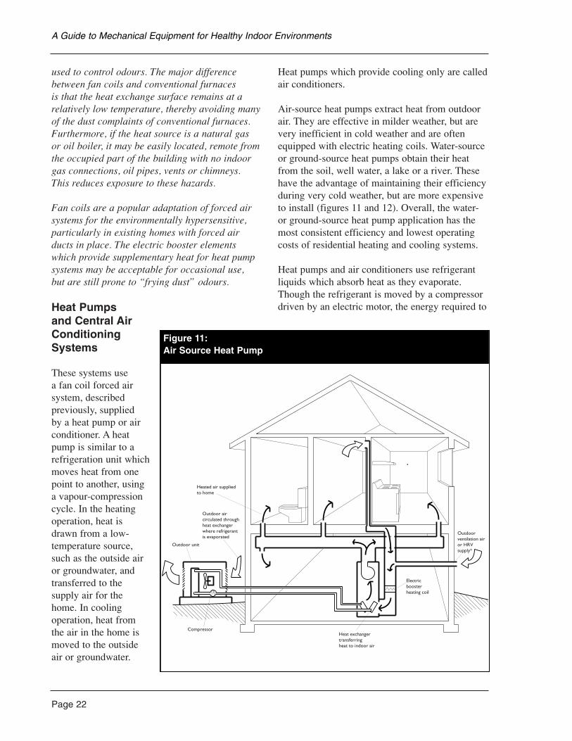
Page 22
used to control odours. The major differencebetween fan coils and conventional furnaces is that the heat exchange surface remains at arelatively low temperature, thereby avoiding manyof the dust complaints of conventional furnaces.Furthermore, if the heat source is a natural gasor oil boiler, it may be easily located, remote fromthe occupied part of the building with no indoorgas connections, oil pipes, vents or chimneys.This reduces exposure to these hazards.
Fan coils are a popular adaptation of forced airsystems for the environmentally hypersensitive,particularly in existing homes with forced airducts in place. The electric booster elementswhich provide supplementary heat for heat pumpsystems may be acceptable for occasional use, but are still prone to “frying dust” odours.
Heat Pumps and Central AirConditioningSystems
These systems use a fan coil forced airsystem, describedpreviously, supplied by a heat pump or airconditioner. A heatpump is similar to arefrigeration unit whichmoves heat from onepoint to another, usinga vapour-compressioncycle. In the heatingoperation, heat isdrawn from a low-temperature source,such as the outside airor groundwater, andtransferred to thesupply air for thehome. In coolingoperation, heat fromthe air in the home ismoved to the outsideair or groundwater.
Heat pumps which provide cooling only are calledair conditioners.
Air-source heat pumps extract heat from outdoorair. They are effective in milder weather, but arevery inefficient in cold weather and are oftenequipped with electric heating coils. Water-sourceor ground-source heat pumps obtain their heatfrom the soil, well water, a lake or a river. Thesehave the advantage of maintaining their efficiencyduring very cold weather, but are more expensiveto install (figures 11 and 12). Overall, the water-or ground-source heat pump application has themost consistent efficiency and lowest operatingcosts of residential heating and cooling systems.
Heat pumps and air conditioners use refrigerantliquids which absorb heat as they evaporate.Though the refrigerant is moved by a compressordriven by an electric motor, the energy required to
A Guide to Mechanical Equipment for Healthy Indoor Environments
Figure 11:Air Source Heat Pump
Heated air suppliedto home
Outdoor unit
Outdoor aircirculated throughheat exchangerwhere refrigerantis evaporated
CompressorHeat exchangertransferringheat to indoor air
Electricboosterheating coil
Outdoorventilation airor HRVsupply*
Figure 11:Air Source Heat Pump
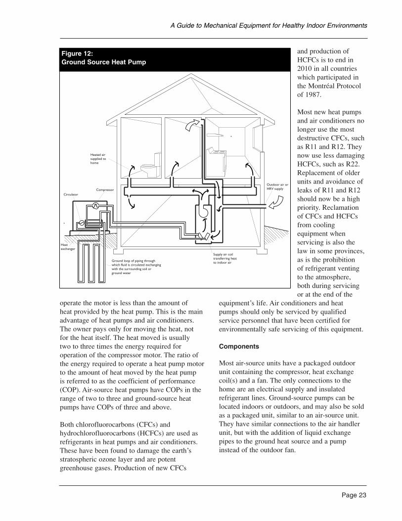
operate the motor is less than the amount of heat provided by the heat pump. This is the mainadvantage of heat pumps and air conditioners.The owner pays only for moving the heat, not for the heat itself. The heat moved is usually two to three times the energy required foroperation of the compressor motor. The ratio ofthe energy required to operate a heat pump motorto the amount of heat moved by the heat pump is referred to as the coefficient of performance(COP). Air-source heat pumps have COPs in therange of two to three and ground-source heatpumps have COPs of three and above.
Both chlorofluorocarbons (CFCs) andhydrochlorofluorocarbons (HCFCs) are used asrefrigerants in heat pumps and air conditioners.These have been found to damage the earth’sstratospheric ozone layer and are potentgreenhouse gases. Production of new CFCs
and production ofHCFCs is to end in2010 in all countrieswhich participated inthe Montréal Protocolof 1987.
Most new heat pumpsand air conditioners nolonger use the mostdestructive CFCs, suchas R11 and R12. Theynow use less damagingHCFCs, such as R22.Replacement of olderunits and avoidance ofleaks of R11 and R12should now be a highpriority. Reclamationof CFCs and HCFCsfrom coolingequipment whenservicing is also thelaw in some provinces,as is the prohibition of refrigerant ventingto the atmosphere, both during servicingor at the end of the
equipment’s life. Air conditioners and heat pumps should only be serviced by qualifiedservice personnel that have been certified forenvironmentally safe servicing of this equipment.
Components
Most air-source units have a packaged outdoorunit containing the compressor, heat exchangecoil(s) and a fan. The only connections to thehome are an electrical supply and insulatedrefrigerant lines. Ground-source pumps can belocated indoors or outdoors, and may also be soldas a packaged unit, similar to an air-source unit.They have similar connections to the air handlerunit, but with the addition of liquid exchangepipes to the ground heat source and a pumpinstead of the outdoor fan.
Page 23
A Guide to Mechanical Equipment for Healthy Indoor Environments
Figure 12:Ground Source Heat Pump
Heated airsupplied tohome
CompressorCirculator
Heatexchanger
Ground loop of piping throughwhich fluid is circulated exchangingwith the surrounding soil or ground water
Supply air coiltransferring heatto indoor air
Outdoor air orHRV supply
Figure 12:Ground Source Heat Pump
Page 24
Heat pumps use fan coils as a means ofexchanging heat to and from the house air. See the fan coil section of this chapter for more details.
General pros and cons
Heat pumps are the most energy-efficient meansof heating using electricity. They can use varioussources of heat and can also provide cooling anddehumidification.
Because the cooling coil may be below thedewpoint temperature under cooling operation,water may condense from the airstream onto thecoil surface. This has the effect of dehumidifyingthe air supplied to the house. Condensed watermust be collected and drained away from the coilwithout pooling in order to prevent the growth ofhazardous bacteria and fungi.
The main disadvantages are the high equipmentcost and the potential noise from air-sourceoutdoor units.
Advantages• Minimal heating of dust.
• Can provide heating and cooling in one unit.
• Fan coil system can provide ventilation and filtration.
• Dehumidifies while cooling.
• Can use air or groundwater as a heat source.
• Energy-efficient use of electricity.
Disadvantages
• High capital costs for whole system forheating and cooling.
• Poorly designed air movement may causediscomfort when heating because deliverytemperature can be low.
• Air movement stirs dust.
• Ducts accumulate dust.
• Space required for ducts.
• Outdoor air-source units may be noisy.
• Higher maintenance costs, more sophisticatedservice people required.
Capital costs and life expectancy
Heat pump units or central air conditionersthemselves cost between about $1,500 and$4,000, depending on size, configuration and options. They last about 10 to 15 years.Groundwater-source heat pumps also require the water collection or underground heat rejectionand collection circuits which can range fromabout $2,500 to $10,000. When coupled with the cost of pumps, piping and air distributionductwork, this places the total system costs as the highest of residential systems. Air-source heatpumps and air conditioners are typically cheaperin capital cost, but more expensive to run thanground-source heat pumps. In return for theincreased investment, a good heat pump systemcan provide excellent air quality, comfort andventilation. Heat pumps are often an appropriatechoice where budget allows.
Operating costs
Electricity is the main operating cost to run the compressor, fans and, possibly, a circulatingpump. For air-source units in Canada, the cost of electric booster coil operation can also besignificant. Total operation costs depend onclimate and system design, but are generally lessthan half of an equivalent amount of electric heat.
Maintenance
Regular maintenance of heat pumps and airconditioners is minimal. A semi-annual inspectionthat includes filter replacement, inspection andcleaning of the coils and drain pan, and annuallubrication of the motors (if required), isrecommended. Compressors are typically sealedunits requiring no maintenance. This is similar
A Guide to Mechanical Equipment for Healthy Indoor Environments
to the maintenance required for forced airfurnaces. However, service requires moresophisticated service people.
Applications for the environmentally hypersensitive
A heat pump as a source of heating and coolinghas the inherent advantage of electric systems in avoiding the use of gas and oil fuels in andaround the home. The heat exchange method islow-temperature and has the merits of providingfor filtration of recirculated air. The maindisadvantages for the environmentallyhypersensitive are the slight risk of refrigerantleaks and the noise generated by an outdoor unit’s fan while operating. Though the risk ofleaks is very small, and the outdoor unit can beinstalled well away from the home to reduce noisecomplaints, these are still concerns for some.
Since heat pumps can provide cooling to theresidence, they allow the possibility of reducingthe outdoor air-exchange rate in the summer. This can be very important to those with a pollenallergy or when outdoor air quality is poor in thesummer. Dehumidification to control mildewgrowth is another important advantage of summer cooling in some regions.
Where a special room or sanctuary is beingprovided for the hypersensitive, it is often isolatedfrom the rest of the home. In this case, a smallsplit-system air conditioner or heat pump may beuseful. These units have a wall-mounted fan coiland a remote outdoor unit which may be locatedseveral metres away from the building, making itfar quieter than a window air conditioner. The fancoil can provide some filtration and ventilation ina few models. See the portable equipment reportsin this chapter for more details.
Convection Heating Systems
Convection heating systems consist of long,narrow heaters usually placed beneath windows(baseboard units) or wall-mounted cabinet units.They heat the space by warming air adjacent tothe heating element which then rises out of the
heater and up the wall by buoyancy. Cooler airenters the heater from below to be warmed. Theheaters may use electricity, may be through-the-wall sealed combustion units (using gas,kerosene, stove oil as fuel), or may be suppliedwith hot water, circulated from an electric or fuel-fired central boiler (hydronic convectors). Someconvection systems are recessed into floors, wallsor cabinets and operate with the assistance of asmall fan (Figure 13).
Similar to furnaces, the primary air qualityconcern with convection heat is the temperatureof the heat exchanger. Conventional electricheaters can produce hot dust odours due to theirhigh surface temperature, but low-temperatureunits, called hydronic convectors, have the sameadvantage as hot water fan coils. These are eitherindividual, liquid-filled electric units, or unitsserved by a boiler. Hydronic heaters operate best at 85°C to 95°C (180°F to 200°F).
There are two types of low-temperature electricconvectors: the low-watt density and liquid-filledtypes. Low-watt density units are simply heaterswith less heat capacity per unit of length, so thesurface temperature remains lower. They requiremore wall space, but can be useful where electricheat is to be used and the budget is limited. Theliquid-filled units have a sealed loop, containingan electric heat element and a heat transfer liquid.Their performance is very similar to hydronicheat, but they require no boiler or plumbing. They are, however, much more costly to buy thanconventional, electric baseboards and have onlyslight operating cost savings if any (Figure 14).
Though convection heating has merit, it cannotprovide ventilation or dehumidification. In order to provide air filtration, humidification,dehumidification or ventilation, a separate airdistribution system must be installed.
Controls
Convectors may be controlled individually, in groups or centrally. While electric units are generally controlled by wall or built-inthermostats, hot water systems are controlled
Page 25
A Guide to Mechanical Equipment for Healthy Indoor Environments
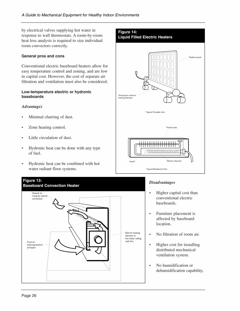
Page 26
by electrical valves supplying hot water inresponse to wall thermostats. A room-by-roomheat loss analysis is required to size individualroom convectors correctly.
General pros and cons
Conventional electric baseboard heaters allow foreasy temperature control and zoning, and are lowin capital cost. However, the cost of separate airfiltration and ventilation must also be considered.
Low-temperature electric or hydronic baseboards
Advantages
• Minimal charring of dust.
• Zone heating control.
• Little circulation of dust.
• Hydronic heat can be done with any type of fuel.
• Hydronic heat can be combined with hotwater radiant floor systems.
Disadvantages
• Higher capital cost thanconventional electricbaseboards.
• Furniture placement isaffected by baseboardlocation.
• No filtration of room air.
• Higher cost for installingdistributed mechanicalventilation system.
• No humidification ordehumidification capability.
A Guide to Mechanical Equipment for Healthy Indoor Environments
Heated airrising by naturalconvection
Electric heatingelement orhot water tubingwith finsCool air
entering bottomof heater
Figure 13:Baseboard Convection Heater
eaters
Radiant panel
Housing for electricheating element
Typical Portable Unit
Typical Baseboard Unit
Finned tube
Liquid Electric element
Figure 14:Liquid Filled Electric Heaters
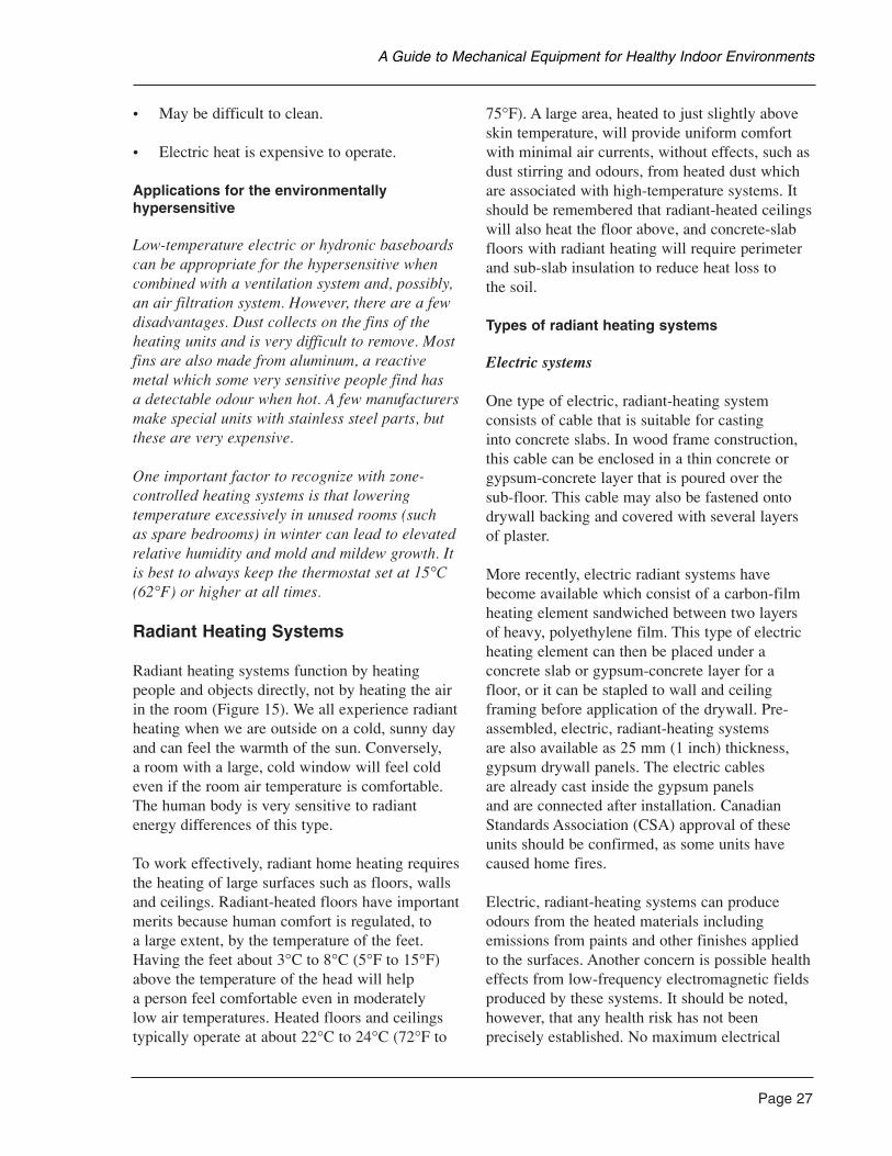
• May be difficult to clean.
• Electric heat is expensive to operate.
Applications for the environmentally hypersensitive
Low-temperature electric or hydronic baseboardscan be appropriate for the hypersensitive whencombined with a ventilation system and, possibly,an air filtration system. However, there are a fewdisadvantages. Dust collects on the fins of theheating units and is very difficult to remove. Mostfins are also made from aluminum, a reactivemetal which some very sensitive people find has a detectable odour when hot. A few manufacturersmake special units with stainless steel parts, butthese are very expensive.
One important factor to recognize with zone-controlled heating systems is that loweringtemperature excessively in unused rooms (such as spare bedrooms) in winter can lead to elevatedrelative humidity and mold and mildew growth. Itis best to always keep the thermostat set at 15°C(62°F) or higher at all times.
Radiant Heating Systems
Radiant heating systems function by heatingpeople and objects directly, not by heating the airin the room (Figure 15). We all experience radiantheating when we are outside on a cold, sunny dayand can feel the warmth of the sun. Conversely, a room with a large, cold window will feel coldeven if the room air temperature is comfortable.The human body is very sensitive to radiantenergy differences of this type.
To work effectively, radiant home heating requiresthe heating of large surfaces such as floors, wallsand ceilings. Radiant-heated floors have importantmerits because human comfort is regulated, to a large extent, by the temperature of the feet.Having the feet about 3°C to 8°C (5°F to 15°F)above the temperature of the head will help a person feel comfortable even in moderately low air temperatures. Heated floors and ceilingstypically operate at about 22°C to 24°C (72°F to
75°F). A large area, heated to just slightly aboveskin temperature, will provide uniform comfortwith minimal air currents, without effects, such asdust stirring and odours, from heated dust whichare associated with high-temperature systems. Itshould be remembered that radiant-heated ceilingswill also heat the floor above, and concrete-slabfloors with radiant heating will require perimeterand sub-slab insulation to reduce heat loss to the soil.
Types of radiant heating systems
Electric systems
One type of electric, radiant-heating systemconsists of cable that is suitable for casting into concrete slabs. In wood frame construction,this cable can be enclosed in a thin concrete orgypsum-concrete layer that is poured over thesub-floor. This cable may also be fastened ontodrywall backing and covered with several layersof plaster.
More recently, electric radiant systems havebecome available which consist of a carbon-filmheating element sandwiched between two layersof heavy, polyethylene film. This type of electricheating element can then be placed under aconcrete slab or gypsum-concrete layer for afloor, or it can be stapled to wall and ceilingframing before application of the drywall. Pre-assembled, electric, radiant-heating systems are also available as 25 mm (1 inch) thickness,gypsum drywall panels. The electric cables are already cast inside the gypsum panels and are connected after installation. CanadianStandards Association (CSA) approval of theseunits should be confirmed, as some units havecaused home fires.
Electric, radiant-heating systems can produceodours from the heated materials includingemissions from paints and other finishes appliedto the surfaces. Another concern is possible healtheffects from low-frequency electromagnetic fieldsproduced by these systems. It should be noted,however, that any health risk has not beenprecisely established. No maximum electrical
Page 27
A Guide to Mechanical Equipment for Healthy Indoor Environments
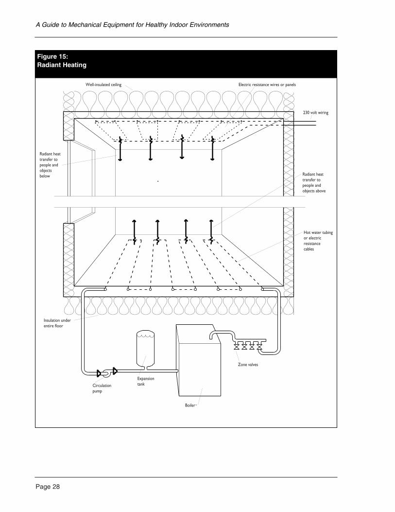
Page 28
A Guide to Mechanical Equipment for Healthy Indoor Environments
gure 15:adiant Heating
Well-insulated ceiling Electric resistance wires or panels
230 volt wiring
Radiant heattransfer to people and objects above
Hot water tubingor electricresistancecables
Zone valves
Boiler
ExpansiontankCirculation
pump
Insulation underentire floor
Radiant heattransfer topeople andobjectsbelow
Figure 15:Radiant Heating
field exposure limits exist for residentialsituations and there are many other sources ofstronger fields in homes. However, the fact thatfields from electric, radiant heating are widelydistributed throughout the house and cannot beavoided, is enough reason for some to take acautious approach and avoid these systems.Furthermore, using resistance electrical heating is a wasteful use of electricity.
It is possible to design electric radiant panels to reduce the field emissions, and this has beendone by some manufacturers. These units may beacceptable choices where electricity will be usedfor heating. Manufacturers and dealers should beasked to provide evidence that their units havebeen designed to minimize electromagnetic field emissions.
Hot water systems
Traditionally, hot water (or hydronic) radiant-heating systems consisted of copper piping, castinto concrete floor slabs. Due to the corrosiveeffect of concrete and the heated water on copper,corrosion leaks in the piping became a problem.Modern systems use plastic piping or metal andplastic composites which can be cast into aconcrete slab, encased in a lightweight concrete or gypsum-concrete topping on wood sub-floors,or enclosed in the floor joist cavity, below woodframed floors.
Similar to convection heating, radiant heatingcannot provide ventilation or dehumidification. In order to provide air filtration, humidification,dehumidification or ventilation, a separate airdistribution system must be installed.
Controls
Similar to convection systems, radiant heatingsystems are generally zoned on a room-by-roombasis, or two or three rooms together. It is alsopossible to zone specific areas within a largerroom. Electric radiant systems are switched bywall-mounted thermostats in the same way aselectric baseboard heaters. Hot water systems are controlled by an electric zone-control valve
connected to a room thermostat similar tohydronic systems. An indoor-outdoor thermostatis often added to hot water systems for additionalcontrol. The thermostat regulates the temperatureof the water in the loop so it is warmer on colderdays and not as warm on mild days. Night setbackthermostats are not appropriate for high-mass(embedded pipe or panel) systems, due to time lags.
A well-designed radiant system can provide very close control of comfort due to the zoningability and flexibility of distribution. More heatshould be supplied in front of a large glass area,for example, rather than along a wall that is well insulated.
General pros and cons
Radiant heating systems can provide very good comfort and do not stir or burn dust. They allow for cooler air temperatures which are often preferred for health reasons. They canalso be invisible in the room and not interferewith furniture placement. However, radiant-floor heating systems generally work best withconcrete, stone or ceramic floor finishes. Layingcarpet and underpad on top of the radiant floorheating is not recommended because thesematerials would be baked by the heat, resulting in significant and serious emissions into the air.Hardwood is sometimes used, but there can beproblems with shrinkage and warping of thematerial and offgassing of adhesives.
Hot water radiant systems can take advantage oflow-temperature energy sources such as those thatmight be available from a solar collector or wasteenergy recovery system. Other hot water heatingsystems, such as forced air and particularlyhydronic baseboard convectors, require a highertemperature fluid in order to work effectively.
Advantages
• Minimal stirring or burning of dust.
• Excellent comfort.
Page 29
A Guide to Mechanical Equipment for Healthy Indoor Environments
Page 30
• Lower air temperatures.
• Accurate local control.
• No obstruction to furniture placement.
• Can be integrated with the domestic hot water system.
• Can use low-temperature energy sources.
• Can take advantage of thermal mass ofmaterials for heat stability.
Disadvantages
• Typical systems are more expensive to installthan other heating systems.
• Slow response time.
• Cannot provide air filtration, cooling or ventilation.
• Additional cost for distributed ventilationsystem.
• Cannot control humidity.
• Incompatible with carpeted floors and some hardwoods.
Capital costs
A very simple system consisting of polybutylenepiping running in the floor joist cavities andsupplied by an efficient water heater can becompetitive with forced air heating for the samehouse. However, more common systems usingmulti-zoned piping loops cast into concrete-topping layers can be very costly—up to threetimes the cost of a forced air system. For fuel-fired systems, the cost of a boiler is usually morethan for a basic warm air furnace of equivalentoutput and efficiency. It can, however, alsoreplace the domestic water heater.
Operating costs
In general, operating a radiant heating system cancost slightly more than baseboard heaters. Radiantheating systems are often selected because theyprovide a high level of comfort and because of the freedom they allow in furniture placement.
Applications for the environmentally hypersensitive
Radiant heating systems have the lowest heatexchange temperatures of all systems and canprovide the best comfort conditions because heat is widely distributed. Air temperature can be kept lower than with other systemscontributing to a feeling of freshness. Radiantsystems do not collect dust or require cleaninglike other heating systems. However, radiantsystems do not provide any ventilation or airfiltration. This must be provided by systemsindependent of the heating system.
Radiant floors are often a preferred heatingsystem when concrete floor construction is used.In most cases, only concrete, ceramic or stonefinishes are used to reduce the risk of offgassingfrom heated finishes such as carpets, paints,woods and adhesives. Though walls, ceilings and wood framed floors can also be heated byradiant systems, there are similar air qualityconcerns which may make it inadvisable for the environmentally hypersensitive unless veryrigorous material selection is done. The safestapproach is to heat ceramic tile only.
Other significant concerns for theenvironmentally hypersensitive are the heatsource, the type of distribution tubing for hotwater radiant systems and the type of concrete orgypsum used to cover the tubing. Generally, onlyelectric, sealed combustion or fully isolatedboilers are recommended. For water distribution,more chemically stable plastic tubing such aspolybutylene and cross-linked polyethylene (a heat-resistant form of polyethylene) are usually acceptable. Plastics such as neoprene(polychloroprene rubber) and ethylene propylenediene monomer (EPDM) should be avoided
A Guide to Mechanical Equipment for Healthy Indoor Environments
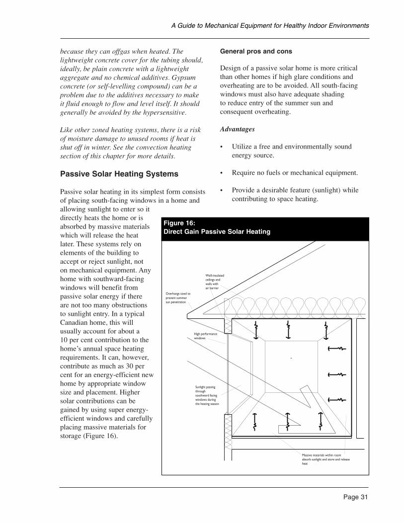
because they can offgas when heated. Thelightweight concrete cover for the tubing should,ideally, be plain concrete with a lightweightaggregate and no chemical additives. Gypsumconcrete (or self-levelling compound) can be aproblem due to the additives necessary to make it fluid enough to flow and level itself. It shouldgenerally be avoided by the hypersensitive.
Like other zoned heating systems, there is a riskof moisture damage to unused rooms if heat isshut off in winter. See the convection heatingsection of this chapter for more details.
Passive Solar Heating Systems
Passive solar heating in its simplest form consistsof placing south-facing windows in a home andallowing sunlight to enter so itdirectly heats the home or isabsorbed by massive materialswhich will release the heatlater. These systems rely onelements of the building toaccept or reject sunlight, not on mechanical equipment. Anyhome with southward-facingwindows will benefit frompassive solar energy if there are not too many obstructionsto sunlight entry. In a typicalCanadian home, this willusually account for about a 10 per cent contribution to thehome’s annual space heatingrequirements. It can, however,contribute as much as 30 percent for an energy-efficient newhome by appropriate windowsize and placement. Highersolar contributions can begained by using super energy-efficient windows and carefullyplacing massive materials forstorage (Figure 16).
General pros and cons
Design of a passive solar home is more criticalthan other homes if high glare conditions andoverheating are to be avoided. All south-facingwindows must also have adequate shading to reduce entry of the summer sun and consequent overheating.
Advantages
• Utilize a free and environmentally soundenergy source.
• Require no fuels or mechanical equipment.
• Provide a desirable feature (sunlight) whilecontributing to space heating.
Page 31
A Guide to Mechanical Equipment for Healthy Indoor Environments
Overhangs sized toprevent summersun penetration
Well-insulatedceilings andwalls withair barrier
High performancewindows
Sunlight passingthroughsouthward facingwindows duringthe heating season
Massive materials within roomabsorb sunlight and store and releaseheat
Figure 16:Direct Gain Passive Solar Heating
Page 32
• Can be used to enhance daylighting andreduce electric lighting.
• Often little or no additional cost over typicalconstruction, when designed from concept.
Disadvantages
• Require a site with direct solar exposure of at least four to six hours per day in late fall,winter and early spring.
• Require more care in design to ensure noglare or overheating.
• May require high capital investment in addedmass and super energy-efficient windows toachieve more than the 30 per cent spaceheating contribution.
• Still require a heating and ventilation system.
Applications for the environmentally hypersensitive
Passive solar heating has substantial merits for the environmentally hypersensitive because fossilfuels can be avoided in the home. Homes withsubstantial south-glazing or solariums also tendto be bright and feel spacious without addedelectric lighting requirements. These qualities areoften noted as very important to hypersensitiveindividuals, particularly in climates where theymay stay indoors for several months of the year.
However, there are two concerns about passivesolar heating in homes for environmentallyhypersensitive individuals. The first is thatmassive materials which may be used as heatstorage in walls and floors become quite warmduring sunny conditions, so the use of paints,adhesives, sealants, textiles, paper coverings and other materials which offgas when warm,must be very restricted. The second concern isthat houses with substantial passive solar heatingability will tend to become very warm on theirsouth exposures during sunny periods and it maybe necessary to distribute heat to other, coolerparts of the house, or vent it. Distributing heat
is often done by mixing warm air with cooler air through an air distribution system, using acontinuously operating fan. The disadvantage for the environmentally hypersensitive is thatodours generated in one part of the house will be distributed throughout, making zoning verydifficult. This is a problem where a particulararea of the house is to be reserved as a sanctuaryfor the hypersensitive. If super energy-efficientwindows with low-emissivity (low-E) coatings are installed, the quality of the light transmittedby the glazing should be addressed (refer to theCMHC publication, Building Materials for theEnvironmentally Hypersensitive). High insulatingproperties are a result of the thermal properties ofthe frame, the types of spacers used and the typeof glazing. Low-emissivity (low-E) windows havecoatings which reduce the infrared radiation orheat lost from the house, resulting in energysavings, but also altering the transmitted light.
Portable Heating and Air Conditioning Equipment
Portable heating equipment
Portable electric convection heaters are a popularsolution for individual room heating, particularlyfor renters and those on a limited budget who find the existing heating system in their homeunacceptable. In homes of the environmentallyhypersensitive, it is common to find a bedroomwhich has been isolated from the forced airheating and a portable electric heater substituted.Generally, the same considerations apply toportable heaters as to permanent convectionheaters. For more information, see the convection heating section of this chapter.
Most conventional portable electric baseboardunits have high-temperature surfaces whichproduce odours from “fried” dust. They also are difficult to clean due to the complex heatexchange fins. A few manufacturers make low-temperature, portable units in either a baseboardor vertical radiator style. These are liquid-filledunits which have the advantages of lower surfacetemperature and better comfort. These are thepreferred portable units for the environmentally
A Guide to Mechanical Equipment for Healthy Indoor Environments
hypersensitive for adapting a single room (Figure 1.10). However, portable heaters, airconditioners or air filtration units can only beexpected to function when used in an enclosedroom of a modest size. These units are notcapable of serving whole houses or large open areas.
Fan-operated portable heaters
Most portable heaters with fans use a high-temperature electric heating element. Theseintroduce dust odour problems. Furthermore, they often have low-quality fans which are noisy, ineffective and produce odours from wiringinsulation and oily residues. This is particularlytrue of very compact units. There are a few largeportable units made which are better quality andhave lower temperature heat exchange elements.These may be acceptable to some environmentallyhypersensitive people. Electric heaters withceramic elements may also be more acceptablethan heaters with metal elements. Ceramics havelower surface temperatures and are less reactive to air contaminants than metal elements.
Painted surfaces and oily residues on new heaterscan also cause irritation to the hypersensitive.These produce odours when heated. A fewspecialized units are available with all stainlesssteel construction, plated metal parts or metallicpaints which eliminate or reduce this problem.
Caution: All portable electric heaters introducefire risks from overheated cords and overloadedelectrical circuits. Manufacturers’ instructionsshould be followed carefully. No extension cordsor oversize fuses should be used and heaters mustbe equipped with safety controls to shut them offif overheated or tipped over.
Portable kerosene, naphtha or propane heaters
Any fuel-burning heater which does not have aneffective chimney to exhaust combustion gasesoutside is a serious health hazard to everyone.Kerosene heaters, camping heaters and fuel-burning construction heaters are not an option for the environmentally hypersensitive.
Air conditioning equipment
Compact air conditioners
Window air conditioners are noisy andproblematic, but are sometimes an importantmeans of providing comfort in existing homes in the hottest and most humid season. They arealso useful for allergic persons during pollenseason because they allow cooling withoutintroducing large amounts of pollen-laden outdoor air. They also can provide some basic air filtration (Figure 17).
A typical unit fits into a window opening or is placed in a dedicated opening in an outsidewall. It contains a small compressor and fan with two heat exchange coils. The evaporatorsurface tends to become quite wet when operatingbecause warm room air loses moisture as itcondenses on the cool surface. This moisture is collected in a drip pan and carried outside by a small tube which must be kept clean.
Some units have controls to select the amount ofoutdoor air mixed with recirculated air and basicfilters. In some cases, filters can be upgraded to a medium-efficiency type which will removesome pollens, dusts and soot from outdoors. The manufacturer should be consulted about filter options.
The main concern with these units, aside from the noise, is the difficulty in keeping them cleanand preventing the growth of microbes in thecondensate pan and drainage system. When dust collects on the evaporator and pan, it mayclog up the drain tube creating conditions whichwill grow fungus or bacteria. Some microbes will produce disagreeable odours and stains while others are a health hazard. If window airconditioners are necessary, it is important thatthey are cleaned and the condensate collectionsystem sterilized regularly.
A split-system air conditioner is a wall-mountedunit containing only the evaporator, a fan andfilters. The noisy compressor is mountedseparately outdoors. These units often have
Page 33
A Guide to Mechanical Equipment for Healthy Indoor Environments
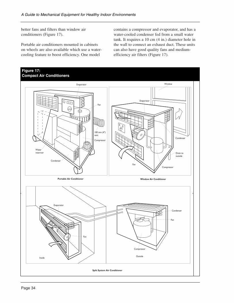
Page 34
better fans and filters than window airconditioners (Figure 17).
Portable air conditioners mounted in cabinets on wheels are also available which use a water-cooling feature to boost efficiency. One model
contains a compressor and evaporator, and has awater-cooled condenser fed from a small watertank. It requires a 10 cm (4 in.) diameter hole inthe wall to connect an exhaust duct. These unitscan also have good quality fans and medium-efficiency air filters (Figure 17).
A Guide to Mechanical Equipment for Healthy Indoor Environments
Figure 17:Compact Air Conditioners
Evaporator
Fan
100 mm (4")vent
Compressor
Condenser
Waterreservoir
Condenser
Evaporator
FanCompressor
Drain tooutside
Window
Condenser
Fan
Compressor
OutsideInside
Fan
Evaporator
Split System Air Conditioner
Portable Air Conditioner Window Air Conditioner
Figure 17:Compact Air Conditioners
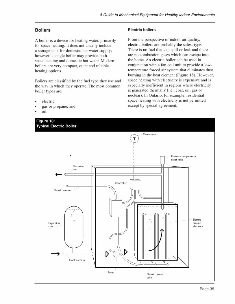
Boilers
A boiler is a device for heating water, primarilyfor space heating. It does not usually include a storage tank for domestic hot water supply;however, a single boiler may provide both space heating and domestic hot water. Modernboilers are very compact, quiet and reliableheating options.
Boilers are classified by the fuel type they use andthe way in which they operate. The most commonboiler types are:
• electric;• gas or propane; and• oil.
Electric boilers
From the perspective of indoor air quality, electric boilers are probably the safest type. There is no fuel that can spill or leak and there are no combustion gases which can escape intothe home. An electric boiler can be used inconjunction with a fan coil unit to provide a low-temperature forced air system that eliminates dustburning in the heat element (Figure 18). However,space heating with electricity is expensive and isespecially inefficient in regions where electricityis generated thermally (i.e., coal, oil, gas ornuclear). In Ontario, for example, residentialspace heating with electricity is not permittedexcept by special agreement.
Page 35
A Guide to Mechanical Equipment for Healthy Indoor Environments
T
Hot water out
Thermostat
Pressure temperaturerelief valve
Electricheatingelements
Electric powercable
Pump
Cool water in
Expansiontank
Electric service
Controller
Figure 18:Typical Electric Boiler
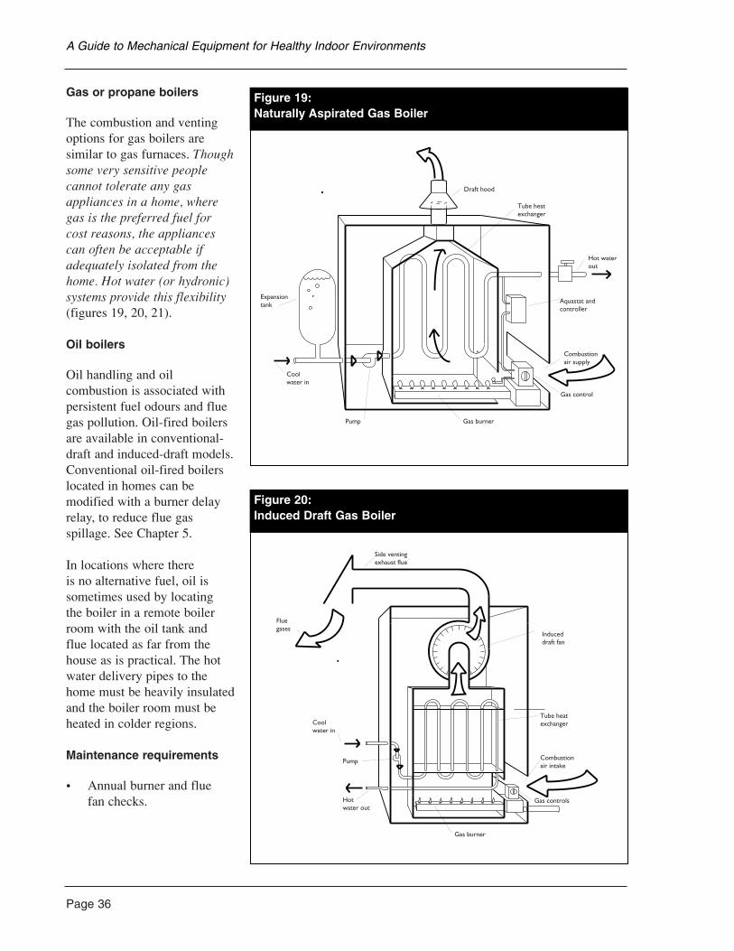
Page 36
Gas or propane boilers
The combustion and ventingoptions for gas boilers aresimilar to gas furnaces. Thoughsome very sensitive peoplecannot tolerate any gasappliances in a home, wheregas is the preferred fuel for cost reasons, the appliancescan often be acceptable ifadequately isolated from thehome. Hot water (or hydronic)systems provide this flexibility(figures 19, 20, 21).
Oil boilers
Oil handling and oilcombustion is associated withpersistent fuel odours and fluegas pollution. Oil-fired boilersare available in conventional-draft and induced-draft models.Conventional oil-fired boilerslocated in homes can bemodified with a burner delayrelay, to reduce flue gasspillage. See Chapter 5.
In locations where there is no alternative fuel, oil issometimes used by locating the boiler in a remote boilerroom with the oil tank and flue located as far from thehouse as is practical. The hotwater delivery pipes to thehome must be heavily insulatedand the boiler room must beheated in colder regions.
Maintenance requirements
• Annual burner and flue fan checks.
A Guide to Mechanical Equipment for Healthy Indoor Environments
Draft hood
Tube heatexchanger
Hot waterout
Aquastat andcontroller
Combustionair supply
Gas control
Gas burnerPump
Coolwater in
Expansiontank
Figure 19:Naturally Aspirated Gas Boiler
raft Gas Boiler
Side ventingexhaust flue
Fluegases
Induceddraft fan
Tube heatexchanger
Combustionair intake
Gas burner
Gas controlsHotwater out
Pump
Coolwater in
Figure 20:Induced Draft Gas Boiler
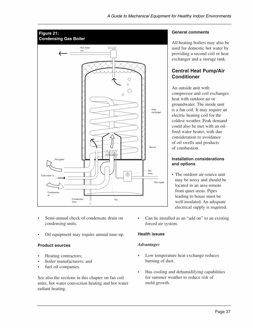
• Semi-annual check of condensate drain oncondensing units.
• Oil equipment may require annual tune-up.
Product sources
• Heating contractors;• boiler manufacturers; and• fuel oil companies.
See also the sections in this chapter on fan coilunits, hot water convection heating and hot waterradiant heating.
General comments
All heating boilers may also beused for domestic hot water byproviding a second coil or heatexchanger and a storage tank.
Central Heat Pump/AirConditioner
An outside unit withcompressor and coil exchangesheat with outdoor air orgroundwater. The inside unit is a fan coil. It may require anelectric heating coil for thecoldest weather. Peak demandcould also be met with an oil-fired water heater, with dueconsideration to avoidance of oil swells and products of combustion.
Installation considerationsand options
• The outdoor air-source unitmay be noisy and should belocated in an area remotefrom quiet areas. Pipesleading to house must be well insulated. An adequateelectrical supply is required.
• Can be installed as an “add on” to an existingforced air system.
Health issues
Advantages
• Low temperature heat exchange reducesburning of dust.
• Has cooling and dehumidifying capabilitiesfor summer weather to reduce risk of mold growth.
Page 37
A Guide to Mechanical Equipment for Healthy Indoor Environments
Gas Boiler
Hot waterout
Heatexchanger
Burner
Gasvalve
Gas supply
FanCondensatedrain
Combustionair
Cold water in
Flue gases
Figure 21:Condensing Gas Boiler
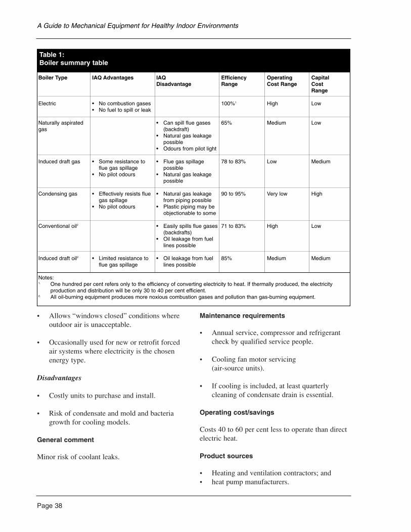
Page 38
• Allows “windows closed” conditions whereoutdoor air is unacceptable.
• Occasionally used for new or retrofit forcedair systems where electricity is the chosenenergy type.
Disadvantages
• Costly units to purchase and install.
• Risk of condensate and mold and bacteriagrowth for cooling models.
General comment
Minor risk of coolant leaks.
Maintenance requirements
• Annual service, compressor and refrigerantcheck by qualified service people.
• Cooling fan motor servicing (air-source units).
• If cooling is included, at least quarterlycleaning of condensate drain is essential.
Operating cost/savings
Costs 40 to 60 per cent less to operate than directelectric heat.
Product sources
• Heating and ventilation contractors; and• heat pump manufacturers.
A Guide to Mechanical Equipment for Healthy Indoor Environments
Table 1:Boiler summary table
Boiler Type IAQ Advantages IAQ Efficiency Operating Capital Disadvantage Range Cost Range Cost
Range
Electric • No combustion gases 100%1 High Low• No fuel to spill or leak
Naturally aspirated • Can spill flue gases 65% Medium Lowgas (backdraft)
• Natural gas leakage possible
• Odours from pilot light
Induced draft gas • Some resistance to • Flue gas spillage 78 to 83% Low Medium flue gas spillage possible
• No pilot odours • Natural gas leakage possible
Condensing gas • Effectively resists flue • Natural gas leakage 90 to 95% Very low Highgas spillage from piping possible
• No pilot odours • Plastic piping may be objectionable to some
Conventional oil2 • Easily spills flue gases 71 to 83% High Low(backdrafts)
• Oil leakage from fuel lines possible
Induced draft oil2 • Limited resistance to • Oil leakage from fuel 85% Medium Mediumflue gas spillage lines possible
Notes:1. One hundred per cent refers only to the efficiency of converting electricity to heat. If thermally produced, the electricity
production and distribution will be only 30 to 40 per cent efficient.2. All oil-burning equipment produces more noxious combustion gases and pollution than gas-burning equipment.
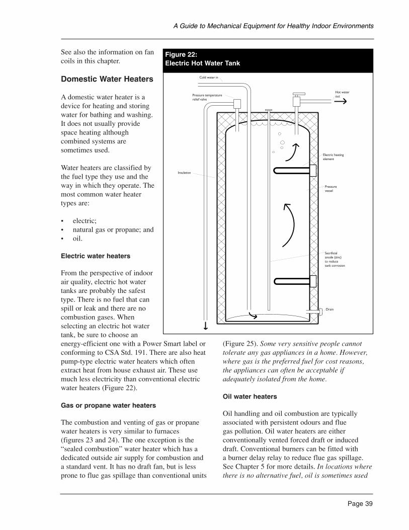
See also the information on fancoils in this chapter.
Domestic Water Heaters
A domestic water heater is adevice for heating and storingwater for bathing and washing.It does not usually providespace heating althoughcombined systems aresometimes used.
Water heaters are classified bythe fuel type they use and theway in which they operate. Themost common water heatertypes are:
• electric;• natural gas or propane; and• oil.
Electric water heaters
From the perspective of indoorair quality, electric hot watertanks are probably the safesttype. There is no fuel that canspill or leak and there are nocombustion gases. Whenselecting an electric hot watertank, be sure to choose anenergy-efficient one with a Power Smart label orconforming to CSA Std. 191. There are also heatpump-type electric water heaters which oftenextract heat from house exhaust air. These usemuch less electricity than conventional electricwater heaters (Figure 22).
Gas or propane water heaters
The combustion and venting of gas or propanewater heaters is very similar to furnaces (figures 23 and 24). The one exception is the“sealed combustion” water heater which has adedicated outside air supply for combustion and a standard vent. It has no draft fan, but is lessprone to flue gas spillage than conventional units
(Figure 25). Some very sensitive people cannottolerate any gas appliances in a home. However,where gas is the preferred fuel for cost reasons,the appliances can often be acceptable ifadequately isolated from the home.
Oil water heaters
Oil handling and oil combustion are typicallyassociated with persistent odours and flue gas pollution. Oil water heaters are eitherconventionally vented forced draft or induceddraft. Conventional burners can be fitted with a burner delay relay to reduce flue gas spillage.See Chapter 5 for more details. In locations wherethere is no alternative fuel, oil is sometimes used
Page 39
A Guide to Mechanical Equipment for Healthy Indoor Environments
t Water Tank
Cold water in
Hot waterout
Electric heatingelement
Pressurevessel
Sacrificialanode (zinc)to reduce tank corrosion
Drain
Pressure temperaturerelief valve
Insulation
Figure 22:Electric Hot Water Tank
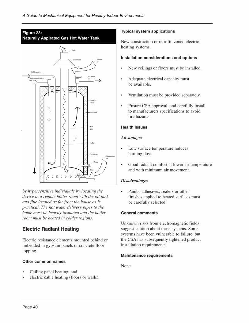
Page 40
by hypersensitive individuals by locating thedevice in a remote boiler room with the oil tankand flue located as far from the house as ispractical. The hot water delivery pipes to thehome must be heavily insulated and the boilerroom must be heated in colder regions.
Electric Radiant Heating
Electric resistance elements mounted behind orimbedded in gypsum panels or concrete floortopping.
Other common names
• Ceiling panel heating; and• electric cable heating (floors or walls).
Typical system applications
New construction or retrofit, zoned electricheating systems.
Installation considerations and options
• New ceilings or floors must be installed.
• Adequate electrical capacity must be available.
• Ventilation must be provided separately.
• Ensure CSA approval, and carefully install to manufacturers specifications to avoid fire hazards.
Health issues
Advantages
• Low surface temperature reduces burning dust.
• Good radiant comfort at lower air temperatureand with minimum air movement.
Disadvantages
• Paints, adhesives, sealers or other finishes applied to heated surfaces must be carefully selected.
General comments
Unknown risks from electromagnetic fieldssuggest caution about these systems. Somesystems have been vulnerable to failure, but the CSA has subsequently tightened productinstallation requirements.
Maintenance requirements
None.
A Guide to Mechanical Equipment for Healthy Indoor Environments
Vent
Draft hood Dilutionair
Hot waterout
Pressurevessel
Insulation
Fluepipe
Baffle
Gas burner
Drain
Pilot
Combustionair
Pressure temperaturerelief valve
Cold water in
Figure 23:Naturally Aspirated Gas Hot Water Tank
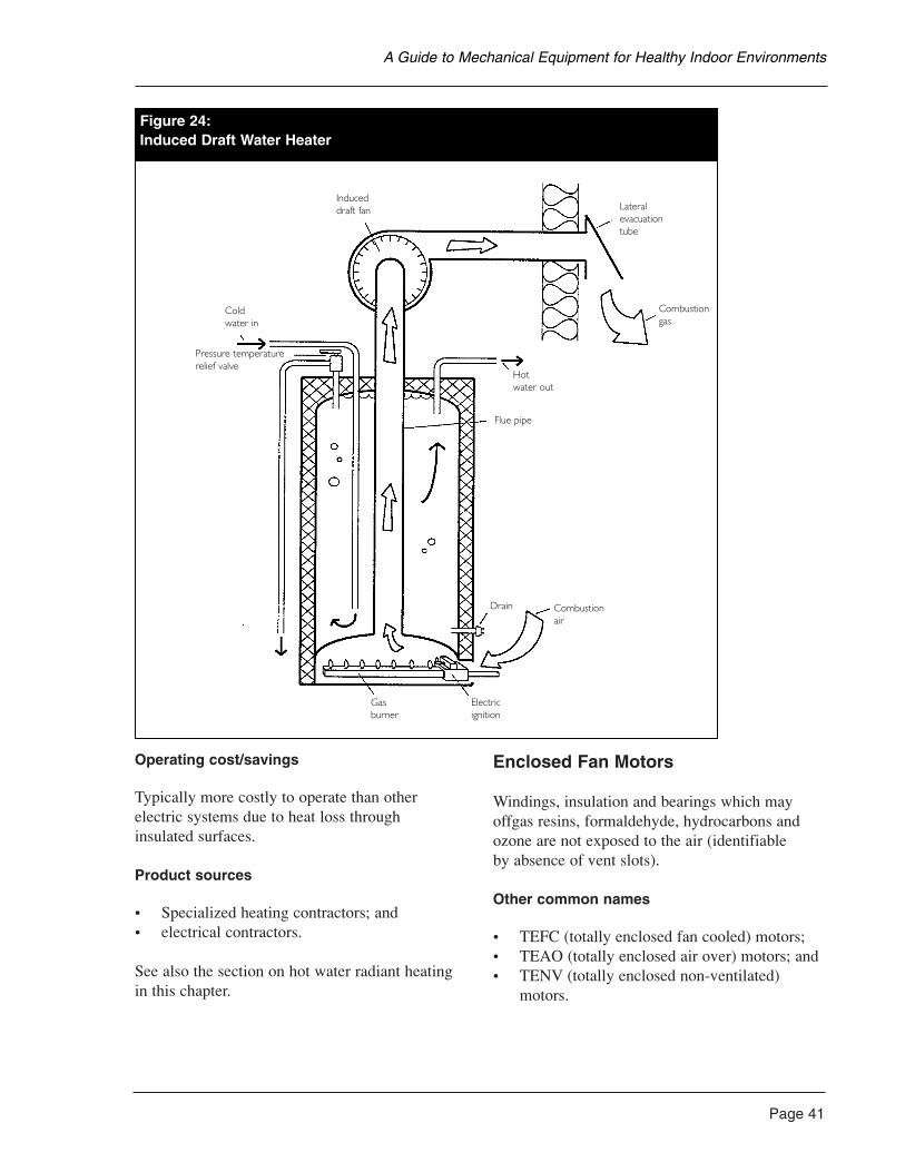
Operating cost/savings
Typically more costly to operate than otherelectric systems due to heat loss through insulated surfaces.
Product sources
• Specialized heating contractors; and• electrical contractors.
See also the section on hot water radiant heatingin this chapter.
Enclosed Fan Motors
Windings, insulation and bearings which mayoffgas resins, formaldehyde, hydrocarbons andozone are not exposed to the air (identifiable by absence of vent slots).
Other common names
• TEFC (totally enclosed fan cooled) motors;• TEAO (totally enclosed air over) motors; and• TENV (totally enclosed non-ventilated)
motors.
Page 41
A Guide to Mechanical Equipment for Healthy Indoor Environments
Figure 24:Induced Draft Water Heater
Induceddraft fan Lateral
evacuationtube
Combustiongas
Hotwater out
Flue pipe
Drain Combustionair
Electricignition
Gasburner
Coldwater in
Pressure temperaturerelief valve
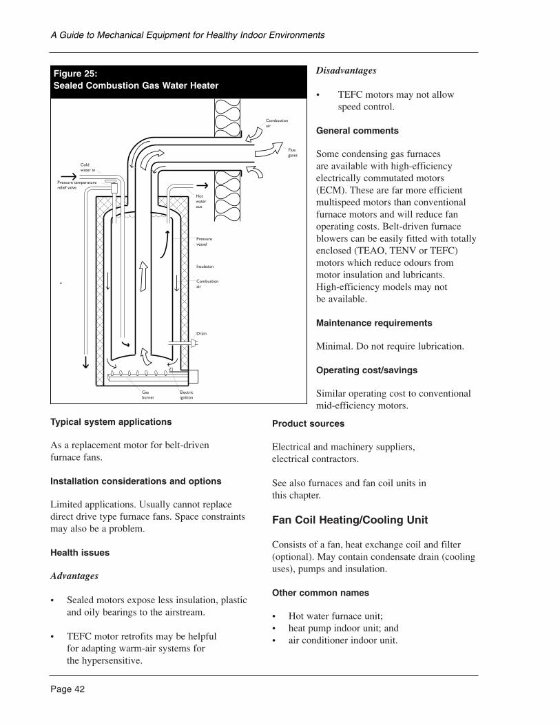
Page 42
Typical system applications
As a replacement motor for belt-driven furnace fans.
Installation considerations and options
Limited applications. Usually cannot replacedirect drive type furnace fans. Space constraintsmay also be a problem.
Health issues
Advantages
• Sealed motors expose less insulation, plasticand oily bearings to the airstream.
• TEFC motor retrofits may be helpful for adapting warm-air systems for the hypersensitive.
Disadvantages
• TEFC motors may not allow speed control.
General comments
Some condensing gas furnaces are available with high-efficiencyelectrically commutated motors(ECM). These are far more efficientmultispeed motors than conventionalfurnace motors and will reduce fanoperating costs. Belt-driven furnaceblowers can be easily fitted with totallyenclosed (TEAO, TENV or TEFC)motors which reduce odours frommotor insulation and lubricants. High-efficiency models may not be available.
Maintenance requirements
Minimal. Do not require lubrication.
Operating cost/savings
Similar operating cost to conventionalmid-efficiency motors.
Product sources
Electrical and machinery suppliers, electrical contractors.
See also furnaces and fan coil units in this chapter.
Fan Coil Heating/Cooling Unit
Consists of a fan, heat exchange coil and filter(optional). May contain condensate drain (coolinguses), pumps and insulation.
Other common names
• Hot water furnace unit;• heat pump indoor unit; and• air conditioner indoor unit.
A Guide to Mechanical Equipment for Healthy Indoor Environments
ombustion Gas Water Heater
Combustionair
Fluegases
Hotwaterout
Pressurevessel
Insulation
Combustionair
Drain
Electricignition
Gasburner
Pressure temperaturerelief valve
Coldwater in
Figure 25:Sealed Combustion Gas Water Heater
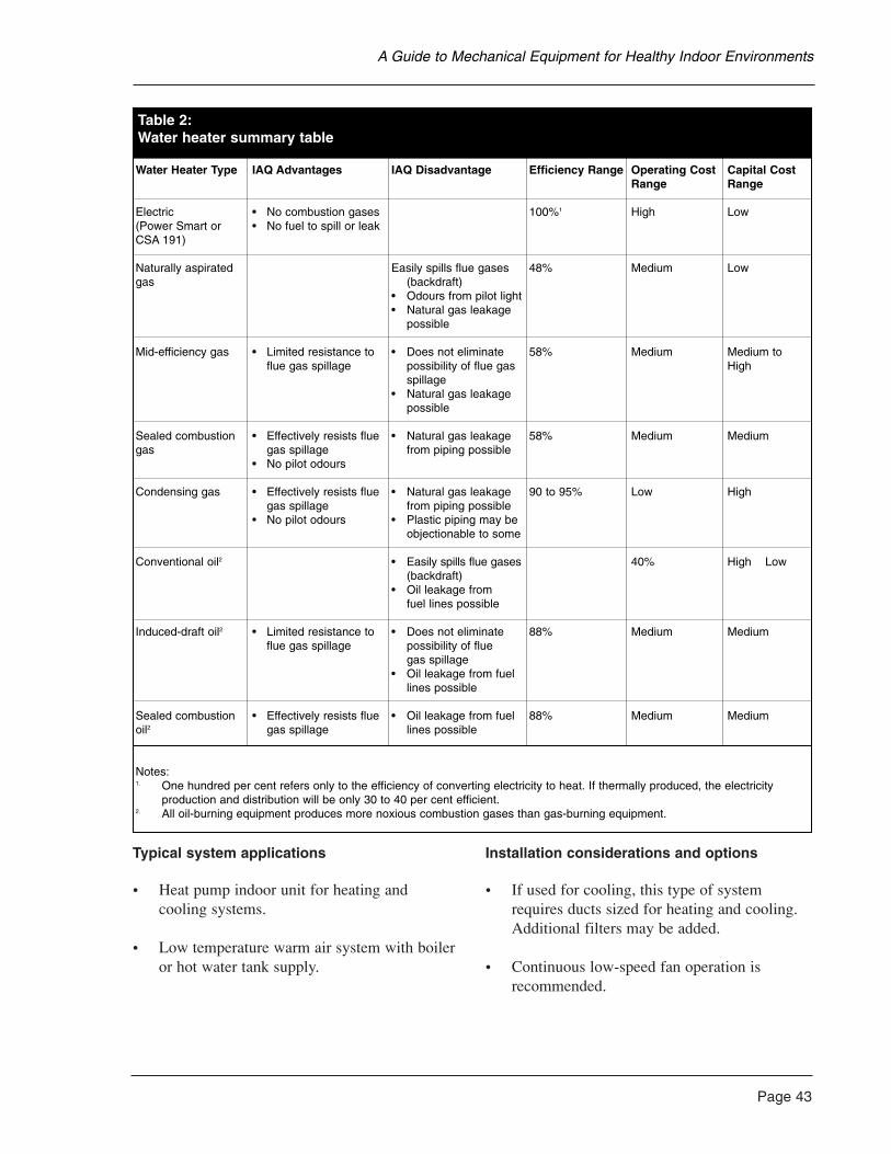
Typical system applications
• Heat pump indoor unit for heating andcooling systems.
• Low temperature warm air system with boileror hot water tank supply.
Installation considerations and options
• If used for cooling, this type of systemrequires ducts sized for heating and cooling.Additional filters may be added.
• Continuous low-speed fan operation isrecommended.
Page 43
A Guide to Mechanical Equipment for Healthy Indoor Environments
Table 2:Water heater summary table
Water Heater Type IAQ Advantages IAQ Disadvantage Efficiency Range Operating Cost Capital Cost Range Range
Electric • No combustion gases 100%1 High Low(Power Smart or • No fuel to spill or leakCSA 191)
Naturally aspirated Easily spills flue gases 48% Medium Lowgas (backdraft)
• Odours from pilot light• Natural gas leakage
possible
Mid-efficiency gas • Limited resistance to • Does not eliminate 58% Medium Medium to flue gas spillage possibility of flue gas High
spillage• Natural gas leakage
possible
Sealed combustion • Effectively resists flue • Natural gas leakage 58% Medium Mediumgas gas spillage from piping possible
• No pilot odours
Condensing gas • Effectively resists flue • Natural gas leakage 90 to 95% Low Highgas spillage from piping possible
• No pilot odours • Plastic piping may be objectionable to some
Conventional oil2 • Easily spills flue gases 40% High Low(backdraft)
• Oil leakage from fuel lines possible
Induced-draft oil2 • Limited resistance to • Does not eliminate 88% Medium Mediumflue gas spillage possibility of flue
gas spillage• Oil leakage from fuel
lines possible
Sealed combustion • Effectively resists flue • Oil leakage from fuel 88% Medium Mediumoil2 gas spillage lines possible
Notes:1. One hundred per cent refers only to the efficiency of converting electricity to heat. If thermally produced, the electricity
production and distribution will be only 30 to 40 per cent efficient.2. All oil-burning equipment produces more noxious combustion gases than gas-burning equipment.
Page 44
• May be retrofitted to replace forced airfurnace or installed as new system.
• Complete package units are now availablecombining furnace, domestic hot water tankand controls in one housing.
Health issues
Advantages
• Low temperature heat exchange reducesburning of dust.
Disadvantages
• Some may have comfort objections tocontinuous air movement.
• Especially in humid conditions, a cooling coil will condense moisture out of the air.This water has to drain away. If the systempermits moisture to remain in the drip tray,this could be a source of mold.
General comments
• Excellent retrofit for forced air furnace ifequipped with additional filters.
• Available as heating or heating/cooling units.
• Can be very compact.
• Can be used to distribute ventilation air.
Maintenance requirements
• Similar to furnaces with occasional filterchanges, duct cleaning and fan motor service.
• If cooling is included, regular cleaning ofcondensate drain is essential.
Operating cost/savings
• Cost depends on efficiency of heating/coolingequipment source.
• Multi-speed, high efficiency fan motor canreduce electrical energy consumption.
Product sources
• Heating and ventilation contractors;• furnace suppliers;• commercial equipment manufacturers; and• power utilities.
See also the sections on boilers, heat pumps andhot water tanks in this chapter and ventilation andair filtration in Chapter 4.
Furnaces
Furnaces are classified by the fuel type they useand the way in which they operate. The mostcommon furnace types are:
• electric;• gas or propane; and• oil.
Electric furnaces
From the perspective of indoor air quality, electric furnaces have the safest fuel type sincethere is no fuel that can spill or leak and there are no combustion gases which can escape intothe home. The main disadvantage of electricfurnaces is the burning of dust on the very hightemperature heat exchanger. The odours producedcan affect very sensitive individuals.
Gas or propane furnaces
Though some very sensitive people cannottolerate any gas appliances in a home, some find it acceptable to have a very well-isolatedgas-burning furnace such as one with a sealedcombustion or induced draft design.
A Guide to Mechanical Equipment for Healthy Indoor Environments
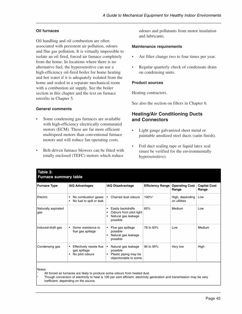
Oil furnaces
Oil handling and oil combustion are oftenassociated with persistent air pollution, odoursand flue gas pollution. It is virtually impossible toisolate an oil fired, forced air furnace completelyfrom the home. In locations where there is noalternative fuel, the hypersensitive can use a high-efficiency oil-fired boiler for home heatingand hot water if it is adequately isolated from thehome and sealed in a separate mechanical roomwith a combustion air supply. See the boilersection in this chapter and the text on furnaceretrofits in Chapter 5.
General comments
• Some condensing gas furnaces are availablewith high-efficiency electrically commutatedmotors (ECM). These are far more efficientmultispeed motors than conventional furnacemotors and will reduce fan operating costs.
• Belt-driven furnace blowers can be fitted withtotally enclosed (TEFC) motors which reduce
odours and pollutants from motor insulationand lubricants.
Maintenance requirements
• Air filter change two to four times per year.
• Regular quarterly check of condensate drainon condensing units.
Product sources
Heating contractors.
See also the section on filters in Chapter 6.
Heating/Air Conditioning Ducts and Connectors
• Light gauge galvanized sheet metal orpaintable anodized steel ducts (satin finish).
• Foil duct sealing tape or liquid latex seal(must be verified for the environmentallyhypersensitive).
Page 45
A Guide to Mechanical Equipment for Healthy Indoor Environments
Table 3:Furnace summary table
Furnace Type IAQ Advantages IAQ Disadvantage Efficiency Range Operating Cost Capital Cost Range Range
Electric • No combustion gases • Charred dust odours 100%2 High, depending Low• No fuel to spill or leak on utilities
Naturally aspirated • Easily backdrafts 65% Medium Lowgas • Odours from pilot light
• Natural gas leakage possible
Induced-draft gas • Some resistance to • Flue gas spillage 78 to 83% Low Medium flue gas spillage possible
• Natural gas leakage possible
Condensing gas • Effectively resists flue • Natural gas leakage 90 to 95% Very low Highgas spillage possible
• No pilot odours • Plastic piping may be objectionable to some
Notes:1. All forced air furnaces are likely to produce some odours from heated dust.2. Though conversion of electricity to heat is 100 per cent efficient, electricity generation and transmission may be very
inefficient, depending on the source.
Page 46
• Mylar or foil-faced flexible duct.
• Extruded aluminium flexible duct.
Typical system applications
• Supply and return ducts for forced air heatingand air conditioning systems.
• Sealers for duct joints.
• Vibration isolating duct connectors.
Installation considerations and options
• All sheet metal ducts are preferred. Woodjoists used as return ducts are difficult toclean and can also contribute odours to the air.
• New sheet metal carries oily residues.Washing with mild detergent or washing soda (sodium carbonate) is recommended.
• Flexible ducts offer higher resistance toairflow and may contribute emissions to the air especially when the air is heated.
Health issues
Advantages
• Metal foil tape is generally less odorous thanfabric tape or liquid duct sealers.
• Anodized steel duct materials may have lessoily residues than conventional galvanized.
Disadvantages
• Vinyl contents of some flexible componentsmay not be acceptable due to odours and offgassing. Careful selection canminimize problems.
Maintenance requirements
Periodic duct vacuum cleaning and inspection.
Product sources
Heating and sheet metal contractors.
See also the section on furnaces and fan coil units in this chapter and the text on ventilation in Chapter 4.
Hot Water Radiant Heating
Plastic or composite tubing carries water at 35ºC to 70ºC to heat floor or ceiling surfaces.
Typical system applications
Zoned heating of concrete floors or wood floorsand ceilings.
Installation considerations and options
• Combined radiant/convection systems are common.
• Systems may be supplied by fuel or anelectric boiler.
• Heated concrete slabs should have insulationat perimeter and beneath.
• Ventilation must be provided separately.
Health issues
Advantages
• Low surface temperature reduces burning dust.
• Good radiant comfort at lower air temperatureand with minimum air movement.
• Radiators, which are often hard to keep clean,are unnecessary in this type of system.
Disadvantages
• Best used on floors with concrete or ceramictile finish. Carpet, wood, gypsum and paintedmaterials may outgas when warm.
A Guide to Mechanical Equipment for Healthy Indoor Environments
General comments
• Low-odour plastic tubing is very importantfor the hypersensitive. Tubing that is exposedabove the floor can contribute odours.Polybutylene or X-link polyethylene aregenerally acceptable.
• Hypersensitive individuals should ensure thatthe concrete contains no admixtures.
• Recommended minimum slab insulation isRSI 2-3.2 (R12-20) at perimeter, and RSI 1-2(R6-12) underneath.
Maintenance requirements
None.
Operating cost/savings
Typically, more costly to operate than forced airsystem due to heat loss through outside surfacesor ground.
Product sources
• Specialized heating contractors; and • plumbing contractors.
See also the section on boilers in this chapter.
Humidifiers
Typically consist of wick and fabric or rotatingdrum units located in bypass airstream.
Typical system applications
Add-on units for forced air systems in dry andcold climates.
Installation considerations and options
• Water supply required.
• Floor drain near unit is recommended.
• Special automatic drain and flush valves are available which reduce maintenancerequirements.
• “Cool mist” units are an option. Thesevaporize water using ultrasonic energy.
• Steam type are also an option, but at highenergy cost.
Health issues
Advantages
• Increased humidity during heating season can relieve respiratory irritation and reduceairborne dust.
• The need for a humidifier should be assessedfirst. Take relative humidity readings with ahygrometer. The relative humidity should notexceed 45 per cent.
Disadvantages
• Risks of microbial contamination cause manyto avoid these units except when conditionsare very dry. Unless the house envelope,especially the windows, is well insulated,condensation will occur in cold weather.
General comments
• Portable humidifiers and humidifier/filterwarm air registers (floor grille replacementswith water reservoir and fabric filter) arepossible options.
• “Cool mist” units should only be operatedwith sterilized, demineralized and filtered water.
Maintenance requirements
Humidifiers must be cleaned and checkedregularly.
Page 47
A Guide to Mechanical Equipment for Healthy Indoor Environments
Page 48
Operating cost/savings
Steam types use a great deal of electricity (about1,500 watts).
Product sources
• Heating contractors;• furnace manufacturers; and• humidifier manufacturers.
See also the section on furnaces in this chapter.
Isolated Fan Motors
Totally enclosed motors are sealed units.Windings, insulation and bearings are not exposed to the air.
Other common names
• TEAO (totally enclosed air over) motors;• TENV(totally enclosed non-ventilated)
motors; and• TEFC (totally enclosed fan cooled) motors.
Typical system applications
As a replacement motor for furnace, fan-coil orheat-pump fans. Belt-drive fan motors are moreeasily replaced than direct-drive types.
Installation considerations and options
Replacement of direct-drive type furnace fans canbe difficult, requiring custom mounting bracketsand parts, or not possible due to non-compatibilitywith furnace control system. Space constraintsmay also be a problem.
Health issues
Advantages
• Sealed motors expose less insulation, plasticand oily bearings to the airstream.
• Totally enclosed motor retrofits may behelpful for adapting warm air systems for the hypersensitive.
Disadvantages
• Totally enclosed motors may not allow speed control.
General comments
High-efficiency models not as readily available.
Maintenance requirements
Minimal, totally enclosed motors usually do notrequire lubrication.
Operating cost/savings
Similar operating cost to conventional motors.
Product sources
Electrical, machinery and agricultural suppliers.
See also the section on furnaces and fan coil unitsin this chapter.
Low-Temperature Convection Heaters
Baseboard-type heaters using hot water suppliedat 75°C to 95°C. Also liquid-filled electricbaseboards or low-watt density electricbaseboards (typically less than 400 W/M).
Other common names
• Hydronic heating (hot water); • liquid-filled electric heaters; and• low-watt density electric baseboard heaters.
Typical system applications
Zoned space heating.
Installation considerations and options
Requires hot water boiler or adequate electrical supply (electric units). Usually zone or single room controlled. Ventilation must beprovided separately.
A Guide to Mechanical Equipment for Healthy Indoor Environments
Health issues
Advantages
• Lower surface temperature reduces burning dust.
• Zoned operation allows isolation of rooms,that is, no air mixing between rooms.
• Liquid-filled electric variety is particularlyuseful for isolated retrofits of one room or suite, where a forced air system is found unacceptable.
Disadvantages
Air filtration is not possible.
General comments
• A 460-volt industrial convectors will operateas low-watt density if supplied at 230 volts.
• Should not be turned down too low in winter or moisture damage may occur inclosed rooms.
Maintenance requirements
Occasional cleaning.
Operating cost/savings
• Hydronic unit operating costs depend onboiler equipment.
• Electric units are similar to other electric heating.
Product sources
• Heating and ventilation contractors;• electrical contractors; • specialty manufacturers; and • plumbing contractors.
See also the sections on boilers and portableheaters in this chapter.
Low-Temperature Portable Heaters
• Low watt density or liquid-filled baseboard-type convector or liquid-filled radiator type.
• Generally 120 volt, 1,500 watt maximum.
• Includes thermostat and safety shut-off.
Typical system applications
Convection heating of single rooms or small areas.
Installation considerations and options
• A separate 120V 15A electrical circuitrequired for each heater.
• Do not use extension cords.
Health issues
Advantages
• Low surface temperature reduces burning dust.
• Good radiant comfort at reduced airtemperature (with large radiator types).
• Good retrofit solution for a special sanctuary room.
Disadvantages
• Special heater finishes may be required (i.e., stainless steel or baked enamel). Plastic,rubber or painted parts are generally notacceptable to the hypersensitive.
General comments
• Must have tip-over safety protection (safetyshut-off).
• Inexpensive solution for renters.
Page 49
A Guide to Mechanical Equipment for Healthy Indoor Environments
Page 50
• Do not use fuel-operated portable heaters.These may produce combustion gases.
• Some people find fan-operated, ceramic units acceptable.
Maintenance requirements
• Occasional check of electrical cord and plug.
• Occasional cleaning.
Operating cost/savings
Same as other electric heating.
Product sources
• Specialty heating suppliers; and• allergy product services.
See also the section on low-temperatureconvection heaters in this chapter.
Passive Solar Heat
Primarily south-facing glazing, high-performancewindows and usually an air circulation system.May also require massive materials for storage.
Typical system applications
As a supplementary heating source in sunny regions.
Installation considerations and options
• Requires an appropriate climate andunobstructed solar exposure.
• Careful design, window sizing and selectionare essential.
• High insulation levels are important.
• Ventilation and air filtration must be provided separately.
Health issues
Advantages
• No fuel consumption, no mechanicalequipment and low temperature surface heating.
• Enhanced daylight and sunlight exposure ininterior spaces.
Disadvantages
• Heat storage surfaces should be finished withlow-emissions materials (i.e., concrete, brickor ceramic).
General comments
Air circulation between rooms is usuallynecessary to distribute heat. This makes it difficult to maintain air quality zones.
Maintenance requirements
None.
Operating cost/savings
Solar energy is free. With high-performancewindows, heat losses are minimized. Twenty toforty per cent solar heat is possible in someclimates with appropriate design.
Product sources
• Solar design consultants;• energy efficiency consultants; and • builders with solar design experience.
A Guide to Mechanical Equipment for Healthy Indoor Environments
Portable/Window or Wall AirConditioners and Compact Split-System Air Conditioners
• Housing containing refrigeration system andair circulating fan. Usually has outside airintake and basic filter.
• Split units have a remote mountedcompressor. These are quieter and more efficient.
• Portable units are available which areinstalled in a hole in the wall or in a modified window opening.
Typical system applications
• Single room cooling and dehumidifying.
• Some units may have heating capability.
• Most units have ventilation ability.
Installation considerations and options
• Separate electrical circuit is required.
• Condensate drain is required.
Health issues
Advantages
• Dehumidifies to control mold and dust mites.
• Can provide ventilation if required with air intake.
• Can provide basic air filtration.
• Allows “windows closed” conditions whereoutdoor air is unacceptable.
Disadvantages
• Risk of contamination of condensate system.
• Noisy when operating (split units are quieter).
General comments
Sometimes the only available means of providing comfort in a room or apartment in hot, humid conditions.
Maintenance requirements
• Condensate system and unit must be keptclean and sterile to prevent microbial growth.
• Regular cleaning.
• Winter shut down.
Operating cost/savings
• Less efficient than typical central heat pumps.
• Air leaks around window units add to heatingand cooling costs.
Product sources
• Department and hardware stores; and• appliance dealers.
Page 51
A Guide to Mechanical Equipment for Healthy Indoor Environments

Page 52
Ventilation is the removal of stale air and excessmoisture from the occupied zones of the house,and the introduction of outdoor air to diluteindoor air contaminants. Ventilation should bedistinguished from air filtration and air cleaning.Only systems which remove air from the home orsupply outside air to the home are referred to asventilation systems.
Mechanical ventilation will:
• provide reliable control over air exchange ifthe house is fairly draft free with a continuousair barrier;
• improve indoor air quality under allcircumstances except where outdoor airquality is worse than the indoor air quality;
• reduce indoor relative humidity levels inwinter when applicable and thereby reducesurface condensation on windows and othercold surfaces; and
• possibly increase the need to supplycombustion air for fuel-burning appliances.
Mechanical ventilation will not:
• be an appropriate method to supplycombustion air to fireplaces, wood stoves andother fuel-burning appliances, which require a separate, dedicated combustion air supply;
• remove all indoor air pollutants such assmoking, odorous hobbies, pets or otherunusual odour sources which exist in a home;
• effectively filter room air;• do much to cool the house in summer or heat
it in winter;• guarantee freedom from condensation; and• operate for free. Ventilation air must be
heated in the winter and cooled in thesummer, increasing operating costs.
Exhausting Pollutants at Source
Concentrated moisture and air pollutants aregenerated by cooking, bathing, laundry and hobbyactivities. These will disperse throughout the
home if not removed at their source. Locatingeffective exhaust fans which remove air from asclosely as possible to the point where pollutantsare generated is an essential part of a ventilationstrategy. Exhaust may be by a simple local fan,such as a kitchen range hood, or it may bethrough a ducted central ventilator or heatrecovery ventilator, drawing from bathrooms and laundry. Exhaust can also be drawn from the closets to remove odours from stored clothing and household goods.
Natural vs. Mechanical Ventilation
Ventilation in housing has traditionally beenprovided by natural means such as openingwindows or through leaks in wall construction.While this approach has an appeal due to itssimplicity and low construction costs, it has thedisadvantage of relying on thermal effects (thestack effect) or wind to move air. Both of theseforces vary with weather conditions. The stackeffect is strongest during winter when the outsideair temperature is low. In late spring, summer and early fall when the outside air temperature iswarmer, the stack effect is weak or non-existent.Wind on most sites is highly variable all year and cannot be relied on for continuous andreliable ventilation. In addition, the random holes and cracks in walls, floors and ceilings do not ensure that all rooms are adequatelyventilated. Uncontrolled leakage can causeuncomfortable drafts.
A complete mechanical ventilation systemexhausts and supplies ventilation air in acontrolled manner. Outdoor ventilation is airbrought in by ducts where it is easily filtered,tempered, distributed and its rate of supplycontrolled (Figure 26).
Ventilation Effectiveness andDistribution
Ventilation effectiveness is a measure of thequantity of outside air actually delivered to
4. Ventilation and Filtration Basics
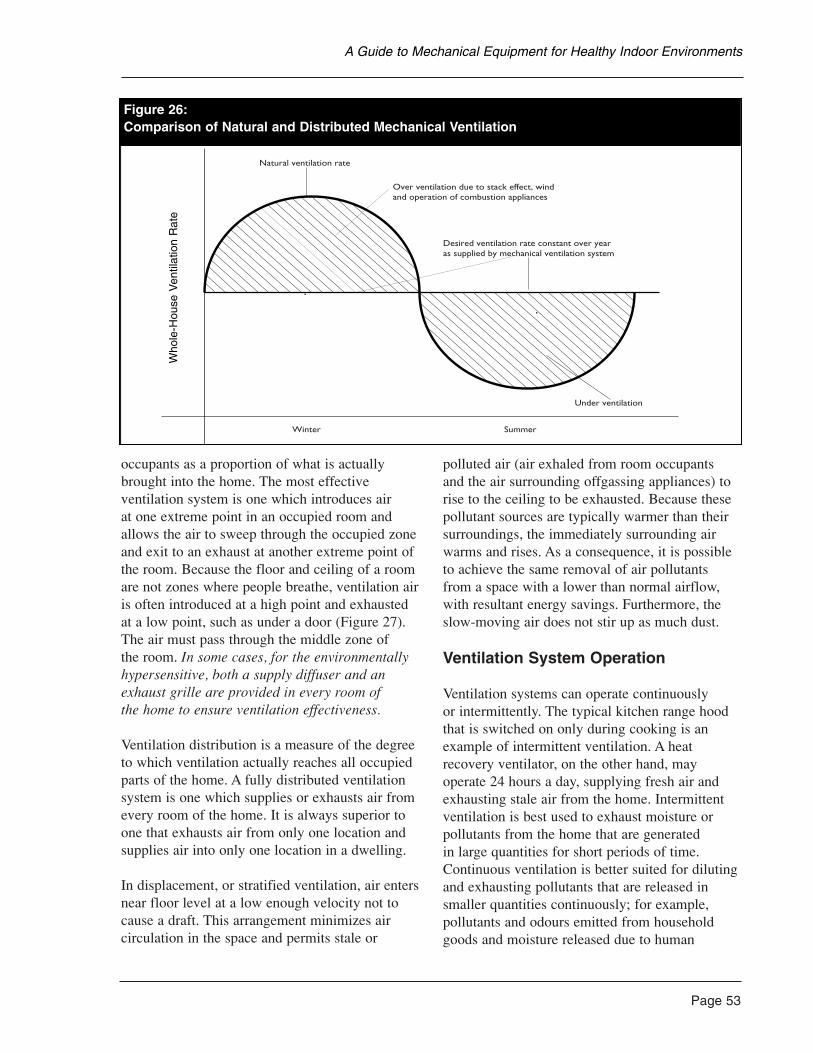
occupants as a proportion of what is actuallybrought into the home. The most effectiveventilation system is one which introduces air at one extreme point in an occupied room andallows the air to sweep through the occupied zoneand exit to an exhaust at another extreme point ofthe room. Because the floor and ceiling of a roomare not zones where people breathe, ventilation airis often introduced at a high point and exhaustedat a low point, such as under a door (Figure 27).The air must pass through the middle zone of the room. In some cases, for the environmentallyhypersensitive, both a supply diffuser and anexhaust grille are provided in every room of the home to ensure ventilation effectiveness.
Ventilation distribution is a measure of the degreeto which ventilation actually reaches all occupiedparts of the home. A fully distributed ventilationsystem is one which supplies or exhausts air fromevery room of the home. It is always superior toone that exhausts air from only one location andsupplies air into only one location in a dwelling.
In displacement, or stratified ventilation, air entersnear floor level at a low enough velocity not tocause a draft. This arrangement minimizes aircirculation in the space and permits stale or
polluted air (air exhaled from room occupants and the air surrounding offgassing appliances) torise to the ceiling to be exhausted. Because thesepollutant sources are typically warmer than theirsurroundings, the immediately surrounding airwarms and rises. As a consequence, it is possibleto achieve the same removal of air pollutants from a space with a lower than normal airflow,with resultant energy savings. Furthermore, theslow-moving air does not stir up as much dust.
Ventilation System Operation
Ventilation systems can operate continuously or intermittently. The typical kitchen range hoodthat is switched on only during cooking is anexample of intermittent ventilation. A heatrecovery ventilator, on the other hand, mayoperate 24 hours a day, supplying fresh air andexhausting stale air from the home. Intermittentventilation is best used to exhaust moisture orpollutants from the home that are generated in large quantities for short periods of time.Continuous ventilation is better suited for dilutingand exhausting pollutants that are released insmaller quantities continuously; for example,pollutants and odours emitted from householdgoods and moisture released due to human
Page 53
A Guide to Mechanical Equipment for Healthy Indoor Environments
Natural ventilation rate
Desired ventilation rate constant over yearas supplied by mechanical ventilation system
Over ventilation due to stack effect, windand operation of combustion appliances
Under ventilation
Winter Summer
Figure 26:Comparison of Natural and Distributed Mechanical Ventilation
Who
le-H
ouse
Ven
tilat
ion
Rat
e
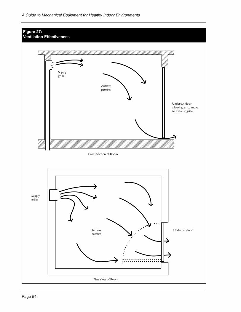
Page 54
A Guide to Mechanical Equipment for Healthy Indoor Environments
ectiveness
Supplygrille
Airflowpattern
Undercut doorallowing air to moveto exhaust grille
Cross Section of Room
Supplygrille
Airflowpattern
Undercut door
Plan View of Room
Figure 27:Ventilation Effectiveness
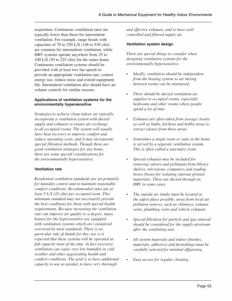
respiration. Continuous ventilation rates aretypically lower than those for intermittentventilation. For example, range hoods withcapacities of 70 to 250 L/S (148 to 530 cfm) are common for intermittent ventilation, whileHRV systems operate anywhere from 25 to 100 L/S (50 to 225 cfm) for the entire home.Continuous ventilation systems should beprovided with at least two fan speeds to provide an appropriate ventilation rate, controlenergy use, reduce noise and extend equipmentlife. Intermittent ventilation also should have airvolume controls for similar reasons.
Applications of ventilation systems for theenvironmentally hypersensitive
Strategies to achieve clean indoor air typicallyincorporate a ventilation system with ductedsupply and exhausts to ensure air exchange in all occupied rooms. The system will usuallyhave heat recovery to improve comfort and reduce operating costs, and it may incorporatespecial filtration methods. Though these are good ventilation strategies for any home, there are some special considerations for the environmentally hypersensitive.
Ventilation rate
Residential ventilation standards are set primarilyfor humidity control and to maintain reasonablecomfort conditions. Recommended rates are atleast 5 L/S (10 cfm) per occupied room. Thisminimum standard may not necessarily providethe best conditions for those with special healthrequirements. Because increasing the ventilationrate can improve air quality to a degree, manyhouses for the hypersensitive are equipped with ventilation systems which are consideredoversized by most standards. There is noparticular rule of thumb for this, nor is itexpected that these systems will be operated atfull capacity most of the time. In fact excessiveventilation can cause very low humidity in coldweather and other aggravating health andcomfort conditions. The goal is to have additionalcapacity to use as needed, to have very thorough
and effective exhausts, and to have well-controlled and filtered supply air.
Ventilation system design
There are special things to consider whendesigning ventilation systems for theenvironmentally hypersensitive.
• Ideally, ventilation should be independentfrom the heating system so air mixing between rooms can be minimized.
• There should be ducted ventilation airsupplies to occupied rooms, especiallybedrooms and other rooms where peoplespend a lot of time.
• Exhausts are often taken from storage closetsas well as baths, kitchens and hobby areas toextract odours from these areas.
• Sometimes a single room or suite in the homeis served by a separate ventilation system.This is often called a sanctuary room.
• Special exhausts may be included forremoving odours and pollutants from libraryshelves, televisions, computers and readingboxes (boxes for isolating odorous printedmaterials). These are ducted through an HRV in some cases.
• The outside air intake must be located in the safest place possible, away from local airpollution sources, such as chimneys, exhaustvents, plumbing vents and vehicle exhausts.
• Special filtration for particle and gas removalshould be considered for the supply airstreamafter the ventilating unit.
• All system materials and indoor finishes,materials, adhesives and furnishings must becarefully selected for minimal offgassing.
• Easy access for regular cleaning.
Page 55
A Guide to Mechanical Equipment for Healthy Indoor Environments
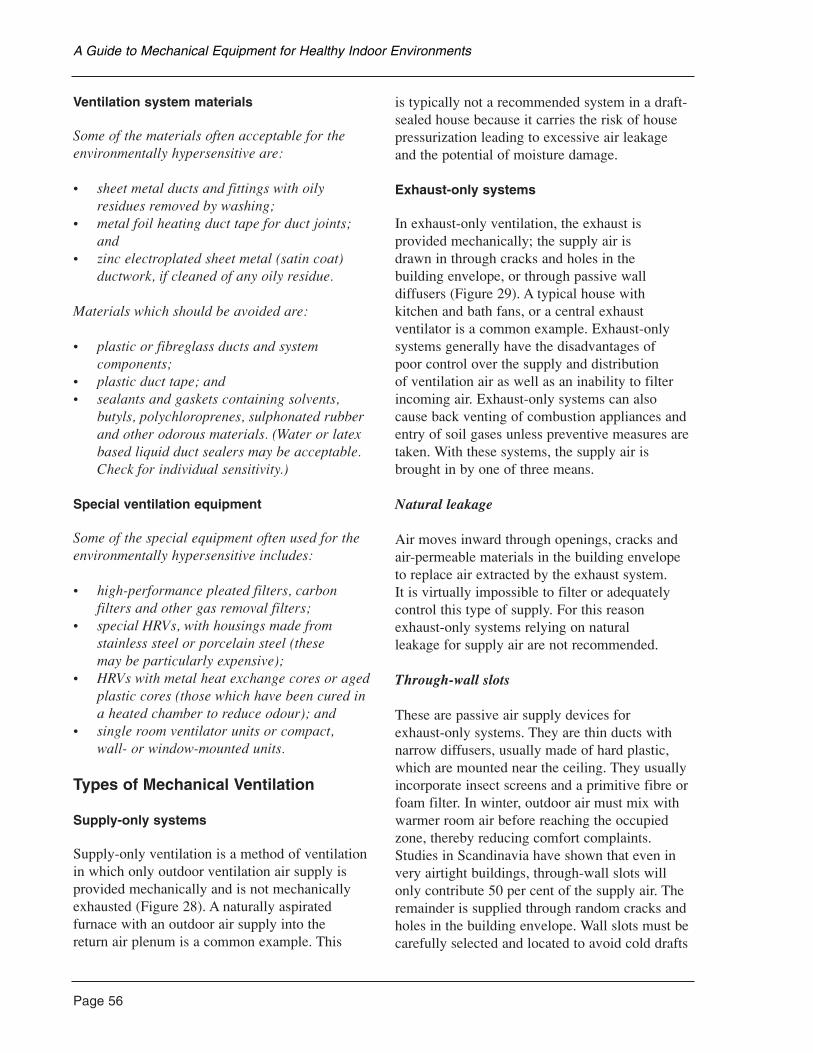
Page 56
Ventilation system materials
Some of the materials often acceptable for theenvironmentally hypersensitive are:
• sheet metal ducts and fittings with oilyresidues removed by washing;
• metal foil heating duct tape for duct joints;and
• zinc electroplated sheet metal (satin coat)ductwork, if cleaned of any oily residue.
Materials which should be avoided are:
• plastic or fibreglass ducts and systemcomponents;
• plastic duct tape; and• sealants and gaskets containing solvents,
butyls, polychloroprenes, sulphonated rubberand other odorous materials. (Water or latexbased liquid duct sealers may be acceptable.Check for individual sensitivity.)
Special ventilation equipment
Some of the special equipment often used for theenvironmentally hypersensitive includes:
• high-performance pleated filters, carbonfilters and other gas removal filters;
• special HRVs, with housings made fromstainless steel or porcelain steel (these may be particularly expensive);
• HRVs with metal heat exchange cores or agedplastic cores (those which have been cured ina heated chamber to reduce odour); and
• single room ventilator units or compact, wall- or window-mounted units.
Types of Mechanical Ventilation
Supply-only systems
Supply-only ventilation is a method of ventilationin which only outdoor ventilation air supply isprovided mechanically and is not mechanicallyexhausted (Figure 28). A naturally aspiratedfurnace with an outdoor air supply into the return air plenum is a common example. This
is typically not a recommended system in a draft-sealed house because it carries the risk of housepressurization leading to excessive air leakage and the potential of moisture damage.
Exhaust-only systems
In exhaust-only ventilation, the exhaust isprovided mechanically; the supply air is drawn in through cracks and holes in the building envelope, or through passive walldiffusers (Figure 29). A typical house with kitchen and bath fans, or a central exhaustventilator is a common example. Exhaust-onlysystems generally have the disadvantages of poor control over the supply and distribution of ventilation air as well as an inability to filterincoming air. Exhaust-only systems can alsocause back venting of combustion appliances andentry of soil gases unless preventive measures aretaken. With these systems, the supply air isbrought in by one of three means.
Natural leakage
Air moves inward through openings, cracks andair-permeable materials in the building envelopeto replace air extracted by the exhaust system. It is virtually impossible to filter or adequatelycontrol this type of supply. For this reasonexhaust-only systems relying on natural leakage for supply air are not recommended.
Through-wall slots
These are passive air supply devices for exhaust-only systems. They are thin ducts withnarrow diffusers, usually made of hard plastic,which are mounted near the ceiling. They usuallyincorporate insect screens and a primitive fibre orfoam filter. In winter, outdoor air must mix withwarmer room air before reaching the occupiedzone, thereby reducing comfort complaints.Studies in Scandinavia have shown that even invery airtight buildings, through-wall slots willonly contribute 50 per cent of the supply air. Theremainder is supplied through random cracks andholes in the building envelope. Wall slots must becarefully selected and located to avoid cold drafts
A Guide to Mechanical Equipment for Healthy Indoor Environments
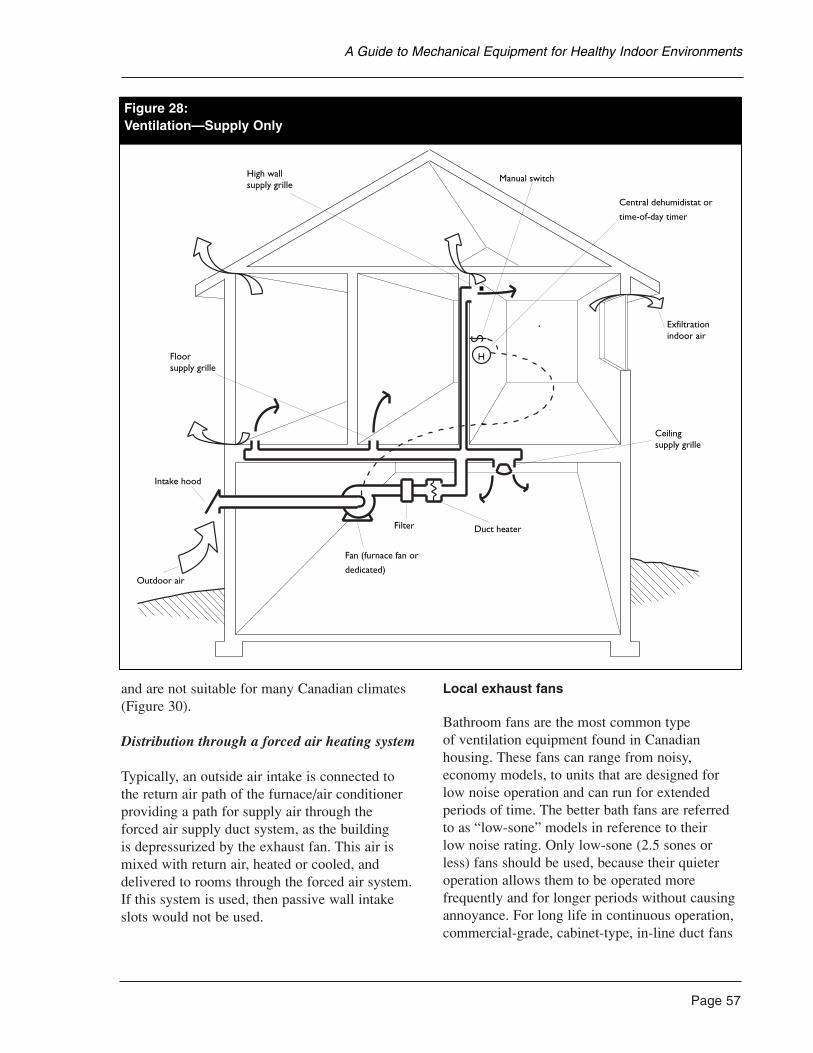
and are not suitable for many Canadian climates(Figure 30).
Distribution through a forced air heating system
Typically, an outside air intake is connected to the return air path of the furnace/air conditionerproviding a path for supply air through the forced air supply duct system, as the building is depressurized by the exhaust fan. This air ismixed with return air, heated or cooled, anddelivered to rooms through the forced air system.If this system is used, then passive wall intakeslots would not be used.
Local exhaust fans
Bathroom fans are the most common type of ventilation equipment found in Canadianhousing. These fans can range from noisy,economy models, to units that are designed forlow noise operation and can run for extendedperiods of time. The better bath fans are referredto as “low-sone” models in reference to their low noise rating. Only low-sone (2.5 sones orless) fans should be used, because their quieteroperation allows them to be operated morefrequently and for longer periods without causingannoyance. For long life in continuous operation,commercial-grade, cabinet-type, in-line duct fans
Page 57
A Guide to Mechanical Equipment for Healthy Indoor Environments
H
Intake hood
Outdoor air
Floorsupply grille
High wallsupply grille
Manual switch
Central dehumidistat or
time-of-day timer
Exfiltrationindoor air
Ceilingsupply grille
Duct heaterFilter
Fan (furnace fan or
dedicated)
Figure 28:Ventilation—Supply Only
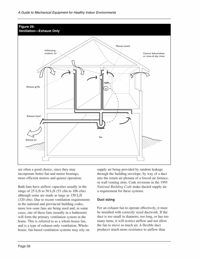
Page 58
are often a good choice, since they mayincorporate better fan and motor bearings, more efficient motors and quieter operation.
Bath fans have airflow capacities usually in therange of 25 L/S to 50 L/S (53 cfm to 106 cfm)although some are made as large as 150 L/S (320 cfm). Due to recent ventilation requirementsin the national and provincial building codes,more low-sone fans are being used and, in somecases, one of these fans (usually in a bathroom)will form the primary ventilation system in thehome. This is referred to as a whole-house fan,and is a type of exhaust-only ventilation. Whole-house, fan-based ventilation systems may rely on
supply air being provided by random leakagethrough the building envelope, by way of a ductinto the return air plenum of a forced air furnace,or wall venting slots. Code revisions in the 1995National Building Code make ducted supply air a requirement for these systems.
Duct sizing
For an exhaust fan to operate effectively, it mustbe installed with correctly sized ductwork. If theduct is too small in diameter, too long, or has toomany turns, it will restrict airflow and not allowthe fan to move as much air. A flexible ductproduces much more resistance to airflow than
A Guide to Mechanical Equipment for Healthy Indoor Environments
H
Exhaust air
Exhaust hood
Infiltratingoutdoor air
Exhaust grille
Manual switch
Central dehumidstat or time-of-day timer
Fan
Figure 29:Ventilation—Exhaust Only
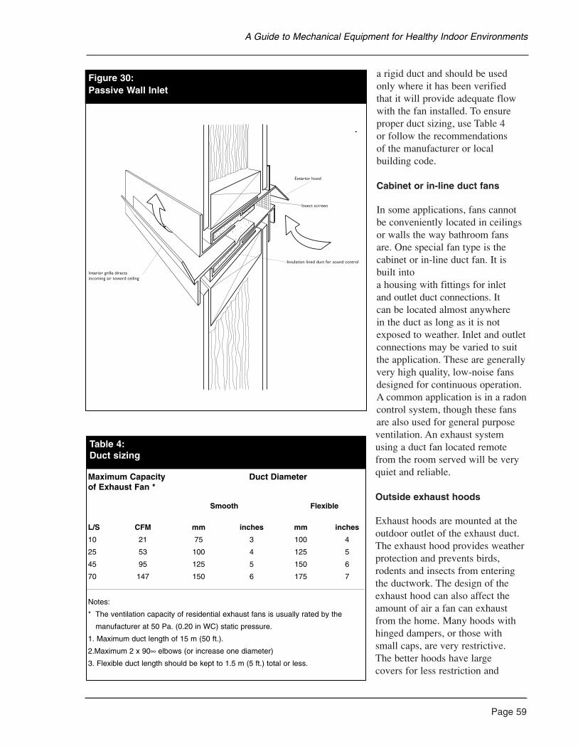
a rigid duct and should be usedonly where it has been verified that it will provide adequate flowwith the fan installed. To ensureproper duct sizing, use Table 4 or follow the recommendations of the manufacturer or localbuilding code.
Cabinet or in-line duct fans
In some applications, fans cannotbe conveniently located in ceilingsor walls the way bathroom fansare. One special fan type is thecabinet or in-line duct fan. It isbuilt into a housing with fittings for inlet and outlet duct connections. It can be located almost anywhere in the duct as long as it is not exposed to weather. Inlet and outletconnections may be varied to suitthe application. These are generallyvery high quality, low-noise fansdesigned for continuous operation.A common application is in a radoncontrol system, though these fansare also used for general purposeventilation. An exhaust systemusing a duct fan located remotefrom the room served will be veryquiet and reliable.
Outside exhaust hoods
Exhaust hoods are mounted at theoutdoor outlet of the exhaust duct.The exhaust hood provides weatherprotection and prevents birds,rodents and insects from enteringthe ductwork. The design of theexhaust hood can also affect theamount of air a fan can exhaustfrom the home. Many hoods withhinged dampers, or those withsmall caps, are very restrictive. The better hoods have large covers for less restriction and
Page 59
A Guide to Mechanical Equipment for Healthy Indoor Environments
Figure 30:Passive Wall Inlet
Exterior hood
Insect scrreen
Insulation lined duct for sound control
Interior grille directsincoming air toward ceiling
Figure 30:Passive Wall Inlet
Table 4:Duct sizing
Maximum Capacity Duct Diameterof Exhaust Fan *
Smooth Flexible
L/S CFM mm inches mm inches
10 21 75 3 100 4
25 53 100 4 125 5
45 95 125 5 150 6
70 147 150 6 175 7
Notes:
* The ventilation capacity of residential exhaust fans is usually rated by the
* manufacturer at 50 Pa. (0.20 in WC) static pressure.
1. Maximum duct length of 15 m (50 ft.).
2.Maximum 2 x 90∞ elbows (or increase one diameter)
3. Flexible duct length should be kept to 1.5 m (5 ft.) total or less.
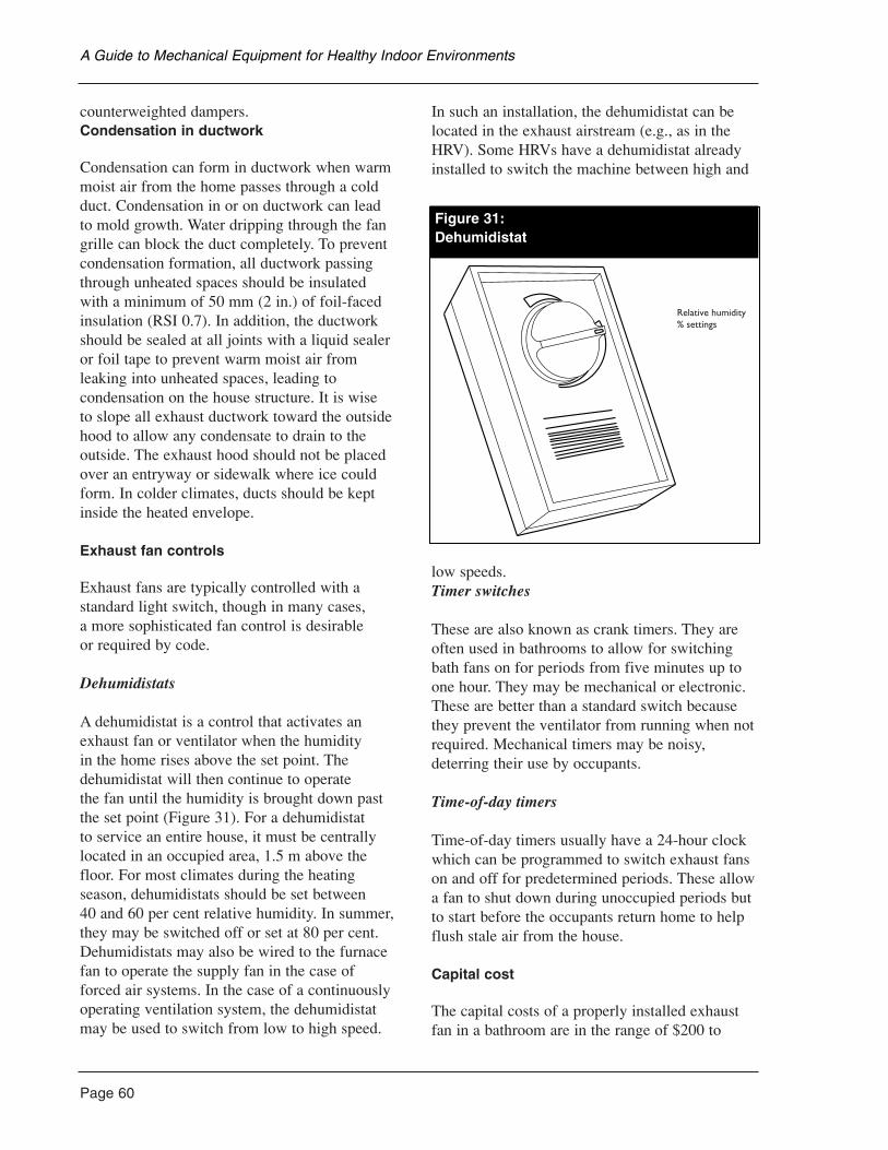
Page 60
counterweighted dampers.Condensation in ductwork
Condensation can form in ductwork when warmmoist air from the home passes through a coldduct. Condensation in or on ductwork can lead to mold growth. Water dripping through the fangrille can block the duct completely. To preventcondensation formation, all ductwork passingthrough unheated spaces should be insulated with a minimum of 50 mm (2 in.) of foil-facedinsulation (RSI 0.7). In addition, the ductworkshould be sealed at all joints with a liquid sealeror foil tape to prevent warm moist air fromleaking into unheated spaces, leading tocondensation on the house structure. It is wise to slope all exhaust ductwork toward the outsidehood to allow any condensate to drain to theoutside. The exhaust hood should not be placedover an entryway or sidewalk where ice couldform. In colder climates, ducts should be keptinside the heated envelope.
Exhaust fan controls
Exhaust fans are typically controlled with astandard light switch, though in many cases, a more sophisticated fan control is desirable or required by code.
Dehumidistats
A dehumidistat is a control that activates anexhaust fan or ventilator when the humidity in the home rises above the set point. Thedehumidistat will then continue to operate the fan until the humidity is brought down pastthe set point (Figure 31). For a dehumidistat to service an entire house, it must be centrallylocated in an occupied area, 1.5 m above thefloor. For most climates during the heatingseason, dehumidistats should be set between 40 and 60 per cent relative humidity. In summer,they may be switched off or set at 80 per cent.Dehumidistats may also be wired to the furnacefan to operate the supply fan in the case of forced air systems. In the case of a continuouslyoperating ventilation system, the dehumidistatmay be used to switch from low to high speed.
In such an installation, the dehumidistat can belocated in the exhaust airstream (e.g., as in theHRV). Some HRVs have a dehumidistat alreadyinstalled to switch the machine between high and
low speeds.Timer switches
These are also known as crank timers. They areoften used in bathrooms to allow for switchingbath fans on for periods from five minutes up toone hour. They may be mechanical or electronic.These are better than a standard switch becausethey prevent the ventilator from running when notrequired. Mechanical timers may be noisy,deterring their use by occupants.
Time-of-day timers
Time-of-day timers usually have a 24-hour clockwhich can be programmed to switch exhaust fanson and off for predetermined periods. These allowa fan to shut down during unoccupied periods butto start before the occupants return home to helpflush stale air from the house.
Capital cost
The capital costs of a properly installed exhaustfan in a bathroom are in the range of $200 to
A Guide to Mechanical Equipment for Healthy Indoor Environments
Relative humidity% settings
Figure 31:Dehumidistat
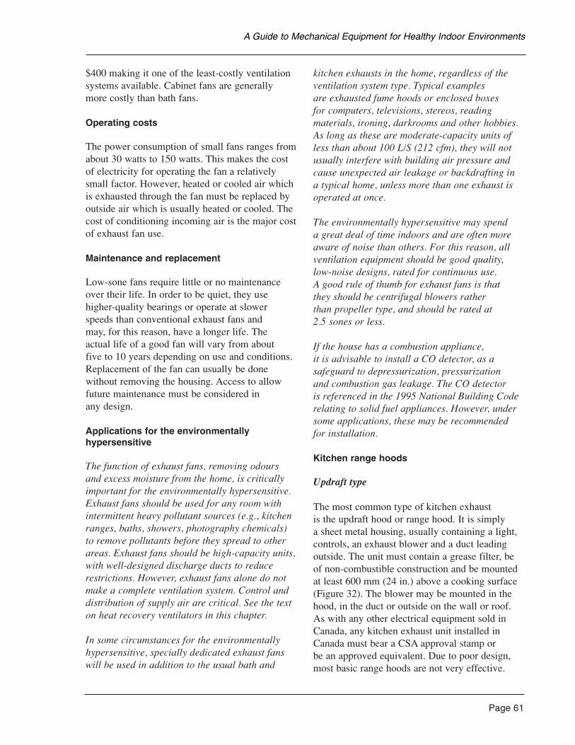
$400 making it one of the least-costly ventilationsystems available. Cabinet fans are generallymore costly than bath fans.
Operating costs
The power consumption of small fans ranges fromabout 30 watts to 150 watts. This makes the costof electricity for operating the fan a relativelysmall factor. However, heated or cooled air whichis exhausted through the fan must be replaced byoutside air which is usually heated or cooled. Thecost of conditioning incoming air is the major costof exhaust fan use.
Maintenance and replacement
Low-sone fans require little or no maintenanceover their life. In order to be quiet, they usehigher-quality bearings or operate at slowerspeeds than conventional exhaust fans and may, for this reason, have a longer life. The actual life of a good fan will vary from about five to 10 years depending on use and conditions.Replacement of the fan can usually be donewithout removing the housing. Access to allowfuture maintenance must be considered in any design.
Applications for the environmentally hypersensitive
The function of exhaust fans, removing odoursand excess moisture from the home, is criticallyimportant for the environmentally hypersensitive.Exhaust fans should be used for any room withintermittent heavy pollutant sources (e.g., kitchenranges, baths, showers, photography chemicals)to remove pollutants before they spread to otherareas. Exhaust fans should be high-capacity units,with well-designed discharge ducts to reducerestrictions. However, exhaust fans alone do notmake a complete ventilation system. Control anddistribution of supply air are critical. See the texton heat recovery ventilators in this chapter.
In some circumstances for the environmentallyhypersensitive, specially dedicated exhaust fanswill be used in addition to the usual bath and
kitchen exhausts in the home, regardless of theventilation system type. Typical examples are exhausted fume hoods or enclosed boxes for computers, televisions, stereos, readingmaterials, ironing, darkrooms and other hobbies.As long as these are moderate-capacity units ofless than about 100 L/S (212 cfm), they will notusually interfere with building air pressure andcause unexpected air leakage or backdrafting in a typical home, unless more than one exhaust isoperated at once.
The environmentally hypersensitive may spend a great deal of time indoors and are often moreaware of noise than others. For this reason, allventilation equipment should be good quality,low-noise designs, rated for continuous use. A good rule of thumb for exhaust fans is that they should be centrifugal blowers rather than propeller type, and should be rated at 2.5 sones or less.
If the house has a combustion appliance, it is advisable to install a CO detector, as asafeguard to depressurization, pressurization and combustion gas leakage. The CO detector is referenced in the 1995 National Building Coderelating to solid fuel appliances. However, undersome applications, these may be recommended for installation.
Kitchen range hoods
Updraft type
The most common type of kitchen exhaust is the updraft hood or range hood. It is simply a sheet metal housing, usually containing a light,controls, an exhaust blower and a duct leadingoutside. The unit must contain a grease filter, beof non-combustible construction and be mountedat least 600 mm (24 in.) above a cooking surface(Figure 32). The blower may be mounted in thehood, in the duct or outside on the wall or roof.As with any other electrical equipment sold inCanada, any kitchen exhaust unit installed inCanada must bear a CSA approval stamp or be an approved equivalent. Due to poor design,most basic range hoods are not very effective.
Page 61
A Guide to Mechanical Equipment for Healthy Indoor Environments
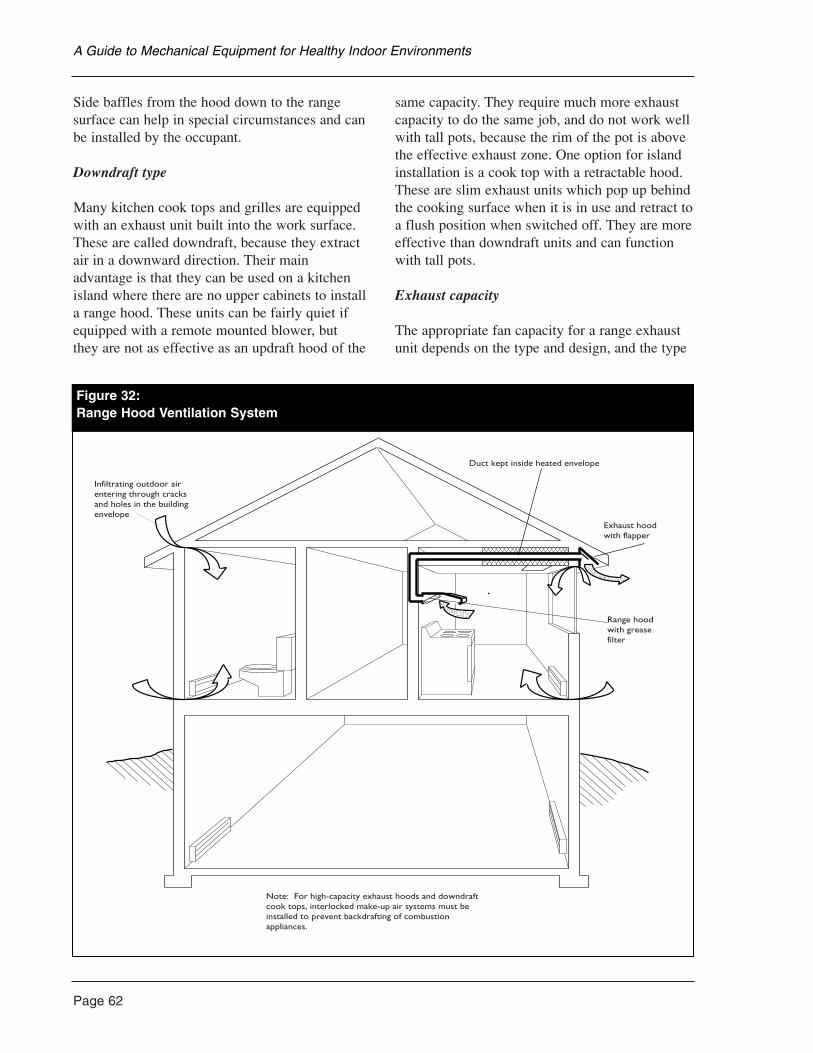
Page 62
Side baffles from the hood down to the rangesurface can help in special circumstances and canbe installed by the occupant.
Downdraft type
Many kitchen cook tops and grilles are equippedwith an exhaust unit built into the work surface.These are called downdraft, because they extractair in a downward direction. Their mainadvantage is that they can be used on a kitchenisland where there are no upper cabinets to installa range hood. These units can be fairly quiet ifequipped with a remote mounted blower, but they are not as effective as an updraft hood of the
same capacity. They require much more exhaustcapacity to do the same job, and do not work wellwith tall pots, because the rim of the pot is abovethe effective exhaust zone. One option for islandinstallation is a cook top with a retractable hood.These are slim exhaust units which pop up behindthe cooking surface when it is in use and retract toa flush position when switched off. They are moreeffective than downdraft units and can functionwith tall pots.
Exhaust capacity
The appropriate fan capacity for a range exhaustunit depends on the type and design, and the type
A Guide to Mechanical Equipment for Healthy Indoor Environments
Duct kept inside heated envelope
Exhaust hoodwith flapper
Range hoodwith greasefilter
Note: For high-capacity exhaust hoods and downdraftcook tops, interlocked make-up air systems must beinstalled to prevent backdrafting of combustionappliances.
Infiltrating outdoor airentering through cracksand holes in the buildingenvelope
Figure 32:Range Hood Ventilation System
of range it serves. The usual high-speed capacityfor a well-designed range hood with a built-in fan is about 150 L/S (318 cfm). Some of the most effective hoods with remote-mountedblowers have a maximum capacity of about 400 L/S (850 cfm). Those which are carefullydesigned and have less restrictive grease filters and ducts can operate with less airflow.Downdraft exhausts always require at least 300 L/S (635 cfm) to operate effectively. These high-capacity models must be carefullyconsidered in relation to fuel-burning equipmentin the home, due to their ability to causebackdrafting of flues.
All units, regardless of size, should have a speed control to allow quieter operation atmoderate speed and to control cold drafts andhouse depressurization. High speed is usuallyonly used for extreme situations such as burnt food.
Ductwork
Only rigid sheet metal ducts are appropriate for range exhausts. The duct size should not be reduced below manufacturers’ specifications.Duct runs should be kept short and with aminimum of bends. All joints should be securelysealed with foil duct tape to prevent leakage andany duct sections passing through unheatedspaces must be insulated to reduce condensation.Due to the risk of grease accumulation, theNational Building Code requires that the duct be accessible for cleaning. Should the duct not be accessible, a grease filter must be provided at the range hood or the exhaust grille at theentrance of the duct.
Capital cost
A basic, effective kitchen range hood with avariable speed control and a moderately quietblower of about 200 L/S (425 cfm) capacity willcost about $350 to $500 installed. High-capacityunits with remote blowers and downdraft unitswill usually cost from $700 to $1,800.
Operating costs
Fan operation is a small part of the operating cost of a kitchen exhaust. However, large-capacityunits used extensively in winter will substantiallyincrease heating costs. The actual amount iswidely variable depending on local weather and conditions.
Maintenance
All kitchen fans require periodic cleaning of thegrease filter and hood surfaces. The frequencywill depend on the type of cooking done. Oilydeposits which are not removed will tend tobecome rancid causing odours and will eventuallyharden. A sodium carbonate (washing soda) andhot water solution is an effective and reasonablysafe cleaning material. Many people wash thegrease filter in a dishwasher. Stainless steel filtersare available, easily cleaned and durable.
Applications for the environmentally hypersensitive
The kitchen exhaust fan is critically important for those sensitive to inhalants. Cooking andsmall appliance use produces a wide range of odours and pollutants including occasional,accidental burning of spilled food. A kitchen must have direct and effective exhaust capacityfor these situations, and constant exhaustoperation during cooking periods is alwaysrecommended for the hypersensitive. The mostimportant considerations for rigorous kitchen air quality are:
• Electric cooking appliances only. Any use of natural gas, propane or any open flame isnot recommended.
• Ceramic or glass top cookers are preferredfor their ease of cleaning.
• Direct vented ovens are preferred. These aretypically only available as wall ovens.
• A hood-type exhaust unit is preferred to adowndraft unit. The hood should be as low
Page 63
A Guide to Mechanical Equipment for Healthy Indoor Environments
Page 64
as is practical over the cooking surfaces, andshould extend beyond the range by at least150 mm on each side if possible.
• A work surface for small appliances, alsounder the hood, is recommended.
• A remote-mounted exhaust blower with avariable speed control is recommendedbecause it is the quietest type.
• Maximum exhaust capacity will typicallyexceed 200 L/S (425 cfm).
• Addition of incombustible (i.e., stainless steel)side baffles extending from the hood to therange surface can significantly aid exhausteffectiveness, but these are inconvenient.
Installation of large-capacity kitchen exhaustsmust consider their possible effects on othersystems in a draft-sealed house. They are notcompatible with conventional fireplaces ornaturally aspirated, naturally vented furnaces,water heaters or boilers. In these circumstances,it may be necessary to provide make-up air (i.e., a supply of outside air to replace the air removedby the exhaust when it is on high speed). Make-upair may need to be preheated to prevent comfortcomplaints. This requires a design by a qualifiedventilation expert.
Non-ducted kitchen range hoods are not anacceptable substitute for a kitchen exhaust. Theseunits recirculate kitchen air through a charcoalfilter, but do not exhaust odours, pollutants andhazardous gases. The charcoal filters becomeloaded with odours very quickly.
Central Exhaust Ventilator
A central exhaust ventilator (CEV) is a singleexhaust fan mounted in a box which typicallydraws air from bathrooms, kitchen and laundryand discharges it through a single duct (Figure 33). A CEV generally has from 60 to 150 L/S capacity (128 to 318 cfm) and can beinstalled in attic spaces, under stairs or, occasionally,basements or crawlspaces. A relatively
inexpensive exhaust-only system option, a CEVis quiet and reliable. The ducting requirements are simple and the units are available packaged as a system, ready to install. It has the samelimitations as all exhaust-only systems in thatsupply air cannot be reliably controlled.
A variant of the central exhaust ventilator is theheat pump exhaust system sometimes used inCanadian houses. Heat pump systems extract heat from exhaust air which is then used to heat domestic hot water.
Duct types and sizing
Some units are equipped with flexible ducts which can be extended, if necessary, by connecting them to rigid sheet metal ducts. Room exhaust duct size is usually 100 mm to 150 mm (4 in. to 6 in.) and main building exhaust150 mm to 200 mm (6 in. to 8 in.). Total flexibleduct length should be minimized and kinks andbends avoided as much as possible.
Duct installation
Condensation can form in ducts exposed to cold air. For this reason, ductwork should be kept inside the heated envelope where possible. If there is a risk of condensation formation, thefan unit should be mounted at a high point and the main exhaust duct sloped downward to theexit point. Furthermore, by running the fancontinuously (on low speed), the risk ofcondensation is reduced.
Supply air options
CEVs can be integrated with forced airheating/cooling systems the same way that other exhaust-only systems can. See the supply air discussion at the beginning of this section.
Capital cost
A packaged CEV unit can be installed in amodest-sized new home for about $500 to $1,000.Passive through-wall slots will add approximately$40 to $60 per room.
A Guide to Mechanical Equipment for Healthy Indoor Environments
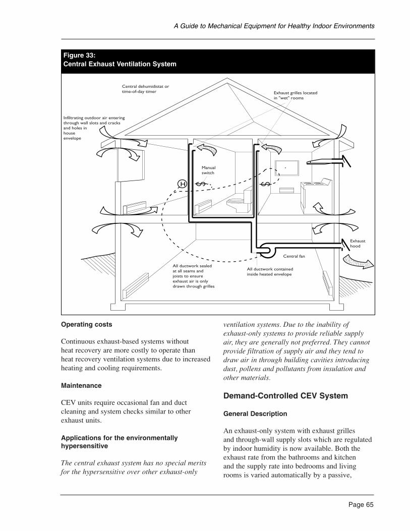
Operating costs
Continuous exhaust-based systems without heat recovery are more costly to operate than heat recovery ventilation systems due to increasedheating and cooling requirements.
Maintenance
CEV units require occasional fan and ductcleaning and system checks similar to otherexhaust units.
Applications for the environmentally hypersensitive
The central exhaust system has no special meritsfor the hypersensitive over other exhaust-only
ventilation systems. Due to the inability ofexhaust-only systems to provide reliable supplyair, they are generally not preferred. They cannotprovide filtration of supply air and they tend todraw air in through building cavities introducingdust, pollens and pollutants from insulation andother materials.
Demand-Controlled CEV System
General Description
An exhaust-only system with exhaust grilles and through-wall supply slots which are regulatedby indoor humidity is now available. Both theexhaust rate from the bathrooms and kitchen and the supply rate into bedrooms and livingrooms is varied automatically by a passive,
Page 65
A Guide to Mechanical Equipment for Healthy Indoor Environments
H
Central fan
Exhausthood
All ductwork containedinside heated envelope
All ductwork sealedat all seams andjoists to ensureexhaust air is onlydrawn through grilles
Infiltrating outdoor air enteringthrough wall slots and cracksand holes inhouseenvelope
Central dehumidistat ortime-of-day timer
Manualswitch
Exhaust grilles locatedin "wet" rooms
Figure 33:Central Exhaust Ventilation System
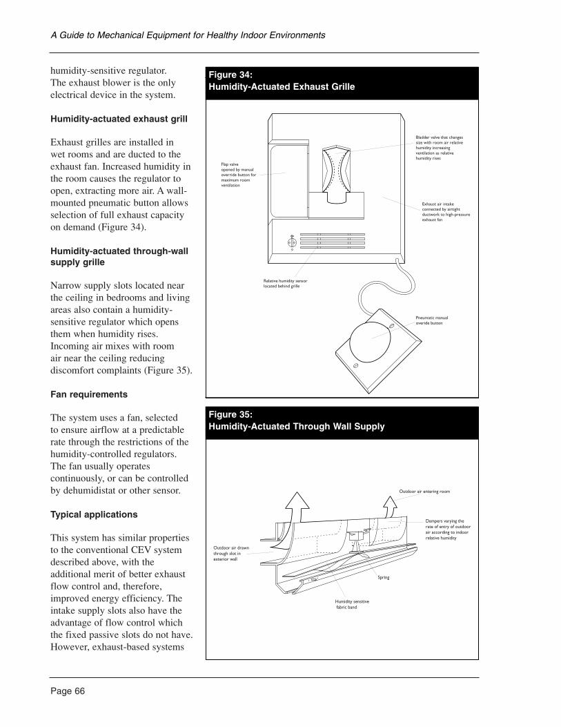
Page 66
humidity-sensitive regulator. The exhaust blower is the onlyelectrical device in the system.
Humidity-actuated exhaust grill
Exhaust grilles are installed in wet rooms and are ducted to theexhaust fan. Increased humidity inthe room causes the regulator toopen, extracting more air. A wall-mounted pneumatic button allowsselection of full exhaust capacityon demand (Figure 34).
Humidity-actuated through-wallsupply grille
Narrow supply slots located nearthe ceiling in bedrooms and livingareas also contain a humidity-sensitive regulator which opensthem when humidity rises.Incoming air mixes with room air near the ceiling reducingdiscomfort complaints (Figure 35).
Fan requirements
The system uses a fan, selected to ensure airflow at a predictablerate through the restrictions of thehumidity-controlled regulators. The fan usually operatescontinuously, or can be controlledby dehumidistat or other sensor.
Typical applications
This system has similar propertiesto the conventional CEV systemdescribed above, with theadditional merit of better exhaustflow control and, therefore,improved energy efficiency. Theintake supply slots also have theadvantage of flow control whichthe fixed passive slots do not have.However, exhaust-based systems
A Guide to Mechanical Equipment for Healthy Indoor Environments
Figure 34:Humidity Actuated Exhaust Grille
Exhaust air intakeconnected by airtightductwork to high-pressureexhaust fan
Bladder valve that changessize with room air relativehumidity increasingventilation as relativehumidity rises
Pneumatic manualoveride button
Relative humidity sensorlocated behind grille
Flap valveopened by manualoverride button formaximum roomventilation
Figure 34:Humidity-Actuated Exhaust Grille
dity Actuated Through Wall Supply
Dampers varying the rate of entry of outdoorair according to indoorrelative humidity
Outdoor air entering room
Spring
Humidity sensitive fabric band
Outdoor air drawnthrough slot inexterior wall
Figure 35:Humidity-Actuated Through Wall Supply
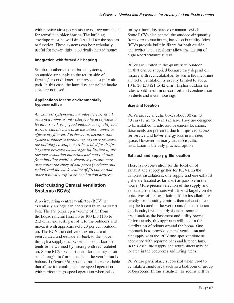
with passive air supply slots are not recommendedfor retrofits to older houses. The buildingenvelope must be well draft sealed for the systemto function. These systems can be particularlyuseful for newer, tight, electrically heated homes.
Integration with forced air heating
Similar to other exhaust-based systems, an outside air supply to the return side of afurnace/air conditioner can provide a supply airpath. In this case, the humidity-controlled intakeslots are not used.
Applications for the environmentally hypersensitive
An exhaust system with air-inlet devices in alloccupied rooms is only likely to be acceptable inlocations with very good outdoor air quality andwarmer climates, because the intake cannot beeffectively filtered. Furthermore, because thissystem produces a continuous negative pressure,the building envelope must be sealed for drafts.Negative pressure encourages infiltration of airthrough insulation materials and entry of dustfrom building cavities. Negative pressure mayalso cause the entry of soil gases (methane andradon) and the back venting of fireplaces andother naturally aspirated combustion devices.
Recirculating Central VentilationSystems (RCVs)
A recirculating central ventilator (RCV) isessentially a single fan contained in an insulatedbox. The fan picks up a volume of air from the house ranging from 50 to 100 L/S (106 to 212 cfm), exhausts part of it to the outdoors andmixes it with approximately 20 per cent outdoorair. The RCV then delivers this mixture ofrecirculated and outside air back to the spacethrough a supply duct system. The outdoor airtends to be warmed by mixing with recirculatedair. Some RCVs exhaust a similar quantity of airas is brought in from outside so the ventilation isbalanced (Figure 36). Speed controls are availablethat allow for continuous low-speed operationwith periodic high-speed operation when called
for by a humidity sensor or manual switch. Some RCVs also control the outdoor air quantityfrom zero to maximum, based on humidity. MostRCVs provide built-in filters for both outside and recirculated air. Some allow installation ofhigher-performance filters.
RCVs are limited in the quantity of outdoor air that can be supplied because they depend onmixing with recirculated air to warm the incomingair. Total ventilation is usually limited to about 10 to 20 L/S (21 to 42 cfm). Higher outdoor airrates would result in discomfort and condensationon ducts and metal housings.
Size and location
RCVs are rectangular boxes about 30 cm to 40 cm (12 in. to 16 in.) in size. They are designedto be installed in attic and basement locations.Basements are preferred due to improved accessfor service and lower energy loss in a heatedspace. However, in many situations, atticinstallation is the only practical option.
Exhaust and supply grille location
There is no convention for the location of exhaust and supply grilles for RCVs. In thesimplest installations, one supply and one exhaustgrille are located as far apart as possible in thehouse. More precise selection of the supply andexhaust grille locations will depend largely on theobjectives of the installation. If the installation isstrictly for humidity control, then exhaust inletsmay be located in the wet rooms (baths, kitchenand laundry) with supply ducts in remote areas such as the basement and utility rooms.Unfortunately, this approach will lead to thedistribution of odours around the home. Oneapproach is to provide general ventilation and air supply with the RCV and spot ventilate asnecessary with separate bath and kitchen fans. In this case, the supply and return ducts may belocated in the bedrooms and living areas.
RCVs are particularly successful when used toventilate a single area such as a bedroom or groupof bedrooms. In this situation, the rooms will be
Page 67
A Guide to Mechanical Equipment for Healthy Indoor Environments

Page 68
well ventilated and good air mixing and somefiltration can be provided. This approach can beused in houses equipped with a forced air systemwhere it is preferred that the forced air system notoperate continuously because of cost or to avoiddistribution of contaminants from other areas of the house.
RCVs may also be successfully used as part of awhole-house distribution strategy where air is tobe moved from a primary occupied area, such as a bedroom, to a secondary area, such as a livingarea, or from a living area to a remote zone, suchas washroom, basement or exhaust closet. In thesesituations, the RCV operates together with otherexhaust fans or with another ventilation system.
RCVs do not have the same air quality and energy conservation benefits as HRVs.Because approximately 80 per cent of the air isrecirculated, air contaminants picked up by theexhaust will be immediately distributed to thesupply location when the ventilator is operating.
Exterior hoods, ducts and duct sizing
The location and selection of intake and exhausthoods is very important for controlling the qualityof supply air. Intakes can be easily contaminatedby auto exhaust, combustion gases, sewer andgarbage odours, and gas and oil services. Ductsmust be sized carefully and insulated in most
A Guide to Mechanical Equipment for Healthy Indoor Environments
gure 36:ecirculating Central Ventilation System
Outside airsupply duct
Recirculating centralventilator
House air and outdoor airmixed in unit, part returnedto house and part exhaustedto outside
Exhaustduct
Baseboard orradiantheating
Figure 36:Recirculating Central Ventilation System
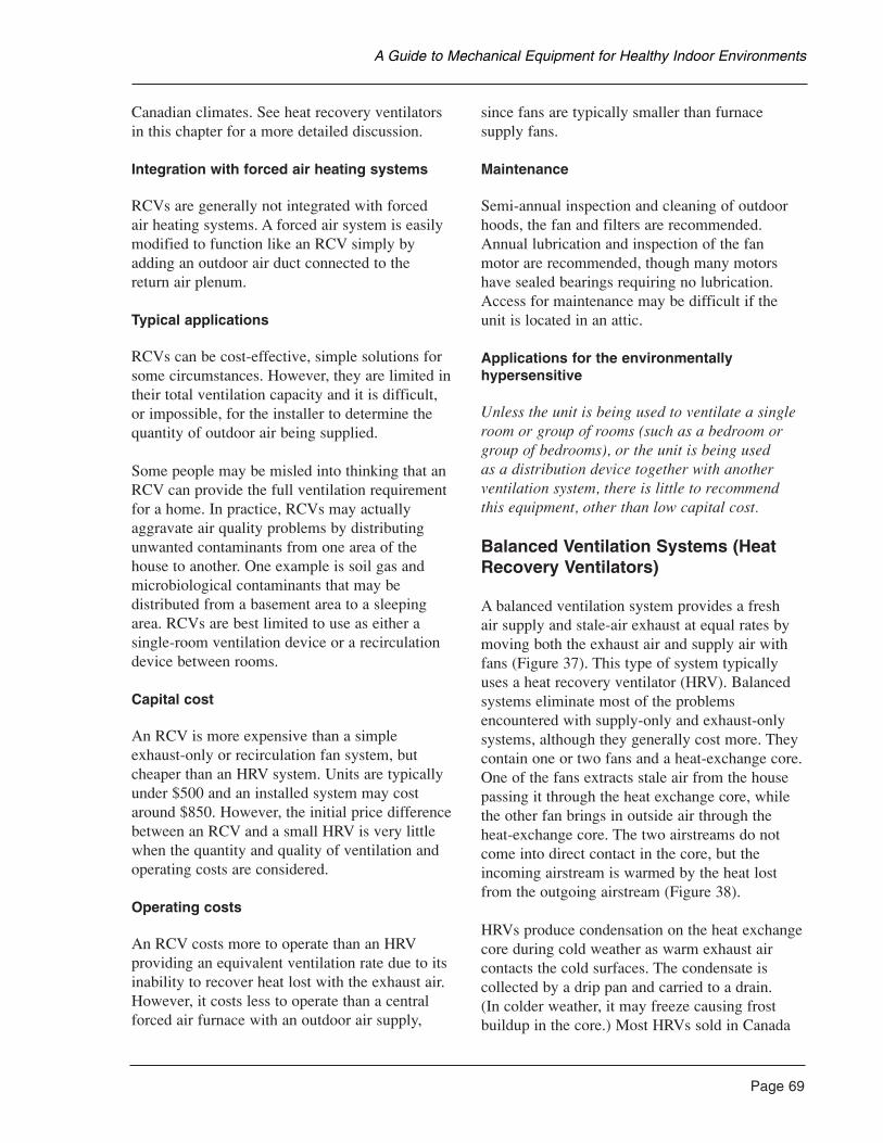
Canadian climates. See heat recovery ventilatorsin this chapter for a more detailed discussion.
Integration with forced air heating systems
RCVs are generally not integrated with forced air heating systems. A forced air system is easilymodified to function like an RCV simply byadding an outdoor air duct connected to the return air plenum.
Typical applications
RCVs can be cost-effective, simple solutions forsome circumstances. However, they are limited intheir total ventilation capacity and it is difficult,or impossible, for the installer to determine thequantity of outdoor air being supplied.
Some people may be misled into thinking that anRCV can provide the full ventilation requirementfor a home. In practice, RCVs may actuallyaggravate air quality problems by distributingunwanted contaminants from one area of thehouse to another. One example is soil gas andmicrobiological contaminants that may bedistributed from a basement area to a sleepingarea. RCVs are best limited to use as either asingle-room ventilation device or a recirculationdevice between rooms.
Capital cost
An RCV is more expensive than a simpleexhaust-only or recirculation fan system, butcheaper than an HRV system. Units are typicallyunder $500 and an installed system may costaround $850. However, the initial price differencebetween an RCV and a small HRV is very littlewhen the quantity and quality of ventilation andoperating costs are considered.
Operating costs
An RCV costs more to operate than an HRVproviding an equivalent ventilation rate due to itsinability to recover heat lost with the exhaust air.However, it costs less to operate than a centralforced air furnace with an outdoor air supply,
since fans are typically smaller than furnacesupply fans.
Maintenance
Semi-annual inspection and cleaning of outdoorhoods, the fan and filters are recommended.Annual lubrication and inspection of the fanmotor are recommended, though many motorshave sealed bearings requiring no lubrication.Access for maintenance may be difficult if theunit is located in an attic.
Applications for the environmentally hypersensitive
Unless the unit is being used to ventilate a singleroom or group of rooms (such as a bedroom orgroup of bedrooms), or the unit is being used as a distribution device together with anotherventilation system, there is little to recommendthis equipment, other than low capital cost.
Balanced Ventilation Systems (HeatRecovery Ventilators)
A balanced ventilation system provides a fresh air supply and stale-air exhaust at equal rates bymoving both the exhaust air and supply air withfans (Figure 37). This type of system typicallyuses a heat recovery ventilator (HRV). Balancedsystems eliminate most of the problemsencountered with supply-only and exhaust-onlysystems, although they generally cost more. Theycontain one or two fans and a heat-exchange core.One of the fans extracts stale air from the housepassing it through the heat exchange core, whilethe other fan brings in outside air through theheat-exchange core. The two airstreams do notcome into direct contact in the core, but theincoming airstream is warmed by the heat lostfrom the outgoing airstream (Figure 38).
HRVs produce condensation on the heat exchangecore during cold weather as warm exhaust aircontacts the cold surfaces. The condensate iscollected by a drip pan and carried to a drain. (In colder weather, it may freeze causing frostbuildup in the core.) Most HRVs sold in Canada
Page 69
A Guide to Mechanical Equipment for Healthy Indoor Environments
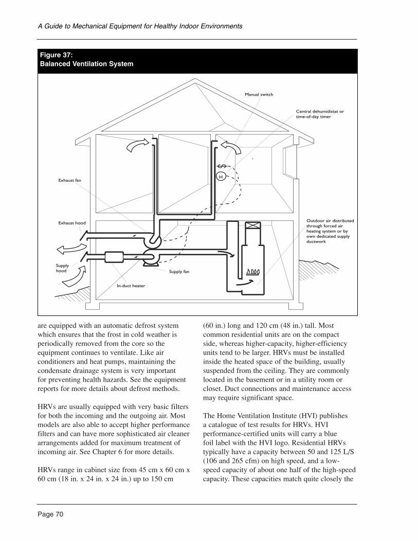
Page 70
are equipped with an automatic defrost systemwhich ensures that the frost in cold weather isperiodically removed from the core so theequipment continues to ventilate. Like airconditioners and heat pumps, maintaining thecondensate drainage system is very important for preventing health hazards. See the equipmentreports for more details about defrost methods.
HRVs are usually equipped with very basic filtersfor both the incoming and the outgoing air. Mostmodels are also able to accept higher performancefilters and can have more sophisticated air cleanerarrangements added for maximum treatment ofincoming air. See Chapter 6 for more details.
HRVs range in cabinet size from 45 cm x 60 cm x60 cm (18 in. x 24 in. x 24 in.) up to 150 cm
(60 in.) long and 120 cm (48 in.) tall. Mostcommon residential units are on the compact side, whereas higher-capacity, higher-efficiencyunits tend to be larger. HRVs must be installedinside the heated space of the building, usuallysuspended from the ceiling. They are commonlylocated in the basement or in a utility room orcloset. Duct connections and maintenance accessmay require significant space.
The Home Ventilation Institute (HVI) publishes a catalogue of test results for HRVs. HVIperformance-certified units will carry a blue foil label with the HVI logo. Residential HRVstypically have a capacity between 50 and 125 L/S(106 and 265 cfm) on high speed, and a low-speed capacity of about one half of the high-speedcapacity. These capacities match quite closely the
A Guide to Mechanical Equipment for Healthy Indoor Environments
igure 37:Balanced Ventilation System
H
In-duct heater
Supply fan
Outdoor air distributedthrough forced airheating system or byown dedicated supplyductwork
Manual switch
Central dehumidistat ortime-of-day timer
Exhaust fan
Exhaust hood
Supplyhood
Figure 37:Balanced Ventilation System
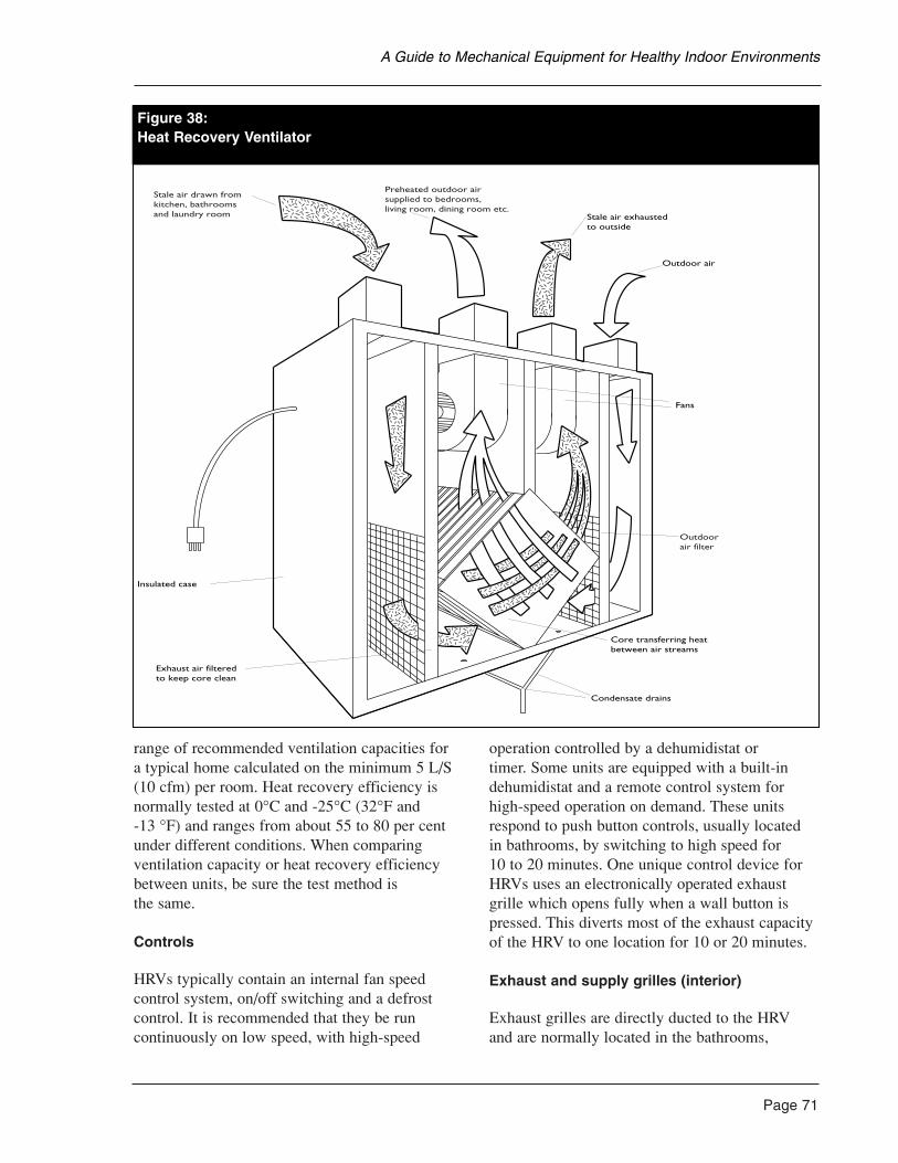
range of recommended ventilation capacities for a typical home calculated on the minimum 5 L/S(10 cfm) per room. Heat recovery efficiency isnormally tested at 0°C and -25°C (32°F and -13 °F) and ranges from about 55 to 80 per centunder different conditions. When comparingventilation capacity or heat recovery efficiencybetween units, be sure the test method is the same.
Controls
HRVs typically contain an internal fan speedcontrol system, on/off switching and a defrostcontrol. It is recommended that they be runcontinuously on low speed, with high-speed
operation controlled by a dehumidistat or timer. Some units are equipped with a built-indehumidistat and a remote control system forhigh-speed operation on demand. These unitsrespond to push button controls, usually located in bathrooms, by switching to high speed for 10 to 20 minutes. One unique control device forHRVs uses an electronically operated exhaustgrille which opens fully when a wall button ispressed. This diverts most of the exhaust capacityof the HRV to one location for 10 or 20 minutes.
Exhaust and supply grilles (interior)
Exhaust grilles are directly ducted to the HRVand are normally located in the bathrooms,
Page 71
A Guide to Mechanical Equipment for Healthy Indoor Environments
Figure 38:Heat Recovery Ventilator
Exhaust air filteredto keep core clean
Insulated case
Stale air exhaustedto outside
Outdoor air
Fans
Condensate drains
Core transferring heat between air streams
Stale air drawn fromkitchen, bathroomsand laundry room
Preheated outdoor airsupplied to bedrooms,living room, dining room etc.
Outdoorair filter
Figure 38:Heat Recovery Ventilator
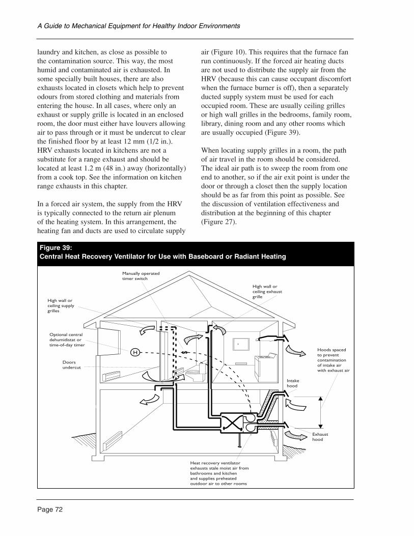
Page 72
laundry and kitchen, as close as possible to the contamination source. This way, the mosthumid and contaminated air is exhausted. In some specially built houses, there are alsoexhausts located in closets which help to preventodours from stored clothing and materials fromentering the house. In all cases, where only anexhaust or supply grille is located in an enclosedroom, the door must either have louvers allowingair to pass through or it must be undercut to clearthe finished floor by at least 12 mm (1/2 in.).HRV exhausts located in kitchens are not asubstitute for a range exhaust and should belocated at least 1.2 m (48 in.) away (horizontally)from a cook top. See the information on kitchenrange exhausts in this chapter.
In a forced air system, the supply from the HRVis typically connected to the return air plenum of the heating system. In this arrangement, theheating fan and ducts are used to circulate supply
air (Figure 10). This requires that the furnace fanrun continuously. If the forced air heating ductsare not used to distribute the supply air from theHRV (because this can cause occupant discomfortwhen the furnace burner is off), then a separatelyducted supply system must be used for eachoccupied room. These are usually ceiling grillesor high wall grilles in the bedrooms, family room,library, dining room and any other rooms whichare usually occupied (Figure 39).
When locating supply grilles in a room, the pathof air travel in the room should be considered.The ideal air path is to sweep the room from oneend to another, so if the air exit point is under thedoor or through a closet then the supply locationshould be as far from this point as possible. Seethe discussion of ventilation effectiveness anddistribution at the beginning of this chapter(Figure 27).
A Guide to Mechanical Equipment for Healthy Indoor Environments
H Hoods spacedto preventcontaminationof intake air with exhaust air
Intakehood
Exhausthood
Heat recovery ventilatorexhausts stale moist air frombathrooms and kitchenand supplies preheatedoutdoor air to other rooms
Doorsundercut
Optional centraldehumidistat ortime-of-day timer
High wall orceiling supplygrilles
Manually operatedtimer switch
High wall orceiling exhaustgrille
Figure 39:Central Heat Recovery Ventilator for Use with Baseboard or Radiant Heating
A small HRV can also be used to ventilate asingle bedroom or group of rooms. The HRVis connected directly to the rooms and exhaust air may be removed from the closet or anadjoining bathroom. In this way, the space may be ventilated independently from the rest of thehouse, without depending on the operation of a central system. Some small HRV units areavailable for this purpose, including wall-mounted units which have very simple ducting arrangements.
Air intake and exhaust (exterior)
HRV intake hoods provide the outside air supplyfor the home and should be carefully placed inorder to obtain the highest-quality air possible.Though only 45 cm (18 in.) clearance abovegrade is usually recommended, much higherlocations are advisable to reduce the risk of entry of debris, automobile exhaust, gardenchemicals and other contaminants. The intakemust be above the snow line. Locations adjacentto chimneys and plumbing vents, as well askitchen and bath exhaust discharges should alsobe avoided. Intakes should always be equippedwith a screen to prevent rodents, birds and insectsfrom entering. As a general rule, HRV intakehoods should be at least 2 m (6.5 ft.) upwind of the nearest pollution source.
Some of the local sources of contamination ofHRV intakes are:• driveways;• barbecues;• gas meters;• oil fillers;• garbage storage areas;• pet areas;• dryer exhausts;• chimneys or gas vents; and• asphalt roofing.
When it is difficult to bring the HRV intakethrough the wall at an ideal location, it can bebrought through elsewhere and connected to anuninsulated duct on the outside of the house inorder to reach a location where better quality air may be obtained. These intake location
considerations apply equally to any building air intake such as an outdoor air connection to a forced air heating system. Because the screen in the air intake hood can become blocked byleaves and debris, the hoods must be accessiblefor cleaning.
Exhaust hoods may be located at practically any location; however, it is best to be at least 1 m (40 in.) from a building opening. If locatedhigh up, it should be in a location where it may be inspected and cleaned, if necessary. An HRVor exhaust fan should never be exhausted into an attic, garage, crawlspace or other enclosedspace. Exhaust hoods should also be equippedwith a backdraft damper, and rodent, insect andbird screen.
Ducts
Both the intake duct from the outdoors and theexhaust duct leading to the outside should beinsulated to prevent condensation, especiallywhere they run through heated spaces. At least 25 mm (1 in.) thick insulation with a vapourbarrier jacket should be used. Often, this isprovided by using vertically slit lengths of pre-insulated flexible ducting, used as a jacket overthe duct. If the intake duct runs for more thanabout 3 m (10 ft.) through a conditioned space,consideration should be given to increasing theamount of insulation used as an energy measure.
When any exhaust or supply air ducts from theHRV to the rooms are installed in an unheatedspace such as an attic, the duct must also beinsulated: 50 mm (2 in.) insulation is usuallyrecommended. The duct should be made asairtight as possible by taping or sealing allconnections, joints and seams. When these ducts are installed in an insulated attic, theyshould be run on the underside of the atticinsulation if possible.
The ventilation designer or contractor willnormally select the appropriate size of duct to use for each situation. In general, exhaust andintake ducts and main supply and return ducts willbe 150 mm or 175 mm (6 in. or 7 in.) in diameter.
Page 73
A Guide to Mechanical Equipment for Healthy Indoor Environments
Page 74
Branch ducts serving one diffuser may be as smallas 75 mm or 100 mm (3 in. or 4 in.). The use offlex duct should be limited both for air qualityand flow-resistance reasons. Short pieces used for vibration isolation and passing throughdifficult frame areas are usually acceptable.
The Heating, Refrigerating and Air ConditioningInstitute of Canada (HRAI) offers certificationcourses for contractors in ventilation and HRVinstallation based on the national ventilationstandard CSA F326. Contractors who have takenthis program and are listed as certified ventilationsystem installers or designers are capable ofdesigning a ductwork system for most residentialapplications. This training should not be confusedwith training provided by local HRAI chapters for provincial building code compliance. HRAI-certified contractors must enter into anarbitration/decertification agreement to provideassurance of a properly designed and installedventilation systems.
Integration with forced air heating systems
HRVs are commonly integrated with forced air heating systems in simplified and hybridarrangements, since supply ductwork does double duty. The hybrid arrangement iseconomical especially if a forced air system exists.
If the primary forced air system fan is notnecessarily intended to be operated continuously,if it does not serve the entire house or if the house is intended to be zoned separately and kept isolated for air quality reasons, then it maybe necessary to consider installing an independentHRV-based ventilation system, even if a forced air system exists. The system will require bothsupply and exhaust ducts throughout theventilated zone. An independent system has merit because ventilation can be controlledseparately from heating and cooling, althoughinitially it costs more.
Capital cost
HRVs are more expensive than exhaust-only orrecirculation ventilation systems. Small-capacity
HRVs installed as simple systems may cost$1,500 to $2,000. Systems with more complexducting and large-capacity, high-performanceHRVs may cost more than $3,000.
Operating costs
Ventilation costs vary with climate, buildingdesign and heating system design. However, onthe basis of amount of ventilation provided, anHRV will provide the lowest operating cost whencompared to all other systems. An HRV-systemcan also be installed independently of the heatingsystem so it can be operated continuously withoutheating fan operation. This will reduce electricalcosts when heating or cooling is not in use.
Maintenance
Occasional inspection and cleaning of outdoorexhaust and inlet hoods, and cleaning of unit and filters is recommended. Fungal contaminationof the air can result from dirty filters within theHRV. Cleaning the filters should be doneregularly. Annual lubrication of the fan motor isrecommended, though many motors have sealedbearings requiring no lubrication.
Applications for the environmentally hypersensitive
An HRV is often the basis for ventilation inhousing where exceptional air quality is required.There are, however, several special considerationswhich should be remembered.
• High ventilation rates will lead to dryness inwinter. Humidification may be required inmany Canadian climates.
• High-performance filtration, including gasscrubbers to remove odours from outdoor air, can be added to the HRV supply duct ifnecessary. In some cases, these will require a separate filter housing. These gas scrubbersmay not be adequate if the outdoor pollutionis high. In these situations, it is best to turnthe HRV off temporarily.
A Guide to Mechanical Equipment for Healthy Indoor Environments
• A small HRV can be used to serve a singleroom, or a group of rooms, if these rooms canbe adequately isolated from the remainder ofthe house.
• HRVs with plastic cores may not beacceptable to the hypersensitive. Aged plasticcores which have been stored in a heatedchamber to reduce odours, or odour-freemetal cores are available for some units.(Stainless steel cores are quite expensive).Enthalpy type HRVs use a core with resinpaper. The environmentally hypersensitiveshould test the core first for tolerability.Aluminum cores are available and should be tested for acceptability.
• All components of the system should becarefully selected to avoid soft plastics, oilyresidues, rubber seals and gaskets, plastictape, caulkings and liquid sealants.
• A unit which does not expose motor windingsto the airstream is preferred because itrequires no lubrication oil.
Special models incorporating many of the above features are not available commerciallyand can be obtained by custom modification ofcommercial units by competent contractors.
Air-Inlet Devices
• Hard plastic or metal units.
• Some have manual control by pull cord.
• Some limited air filtration ability.
Other common names
• Passive vents;• passive slot diffusers; and• high-wall diffusers.
Typical system applications
• Introduce and distribute outdoor ventilationair directly into room. Used with controlledexhaust systems.
• Usually used in bedrooms and living rooms.
Installation considerations and options
• Must be carefully located to avoid cold drafts.High wall location near ceiling preferred.
• Should be as far as possible from exhaustpoint in room.
• A unique unit provides airflow control basedon indoor relative humidity.
Health issues
Advantages
• Can provide cleaner supply air (than byinfiltration) for exhaust-only systems.
Disadvantages
• No filtration possible, not appropriate forpolluted regions.
General comments
Not acceptable in very cold climates.
Maintenance requirements
Periodic cleaning; the filters are usually washable.
Product sources
Specialty ventilation suppliers.
See also the information on control exhaustsystems and exhaust fans in this chapter.
Page 75
A Guide to Mechanical Equipment for Healthy Indoor Environments
Page 76
Central Exhaust Ventilator
This type of fan is installed in a box with severalexhaust ducts, connected to humid rooms andwith an outside discharge.
Other common names
• Ducted, whole-house fan; and• CEV.
Typical system applications
For bathroom, kitchen and laundry exhaust withany type of heating system.
Installation considerations and options
• Unit may be located in attic or basement.Flexduct connections are often provided with unit.
• Unique system with humidity-controlled airinlets and exhaust is available.
• Exhaust duct must be sloped down to thedischarge point.
Health issues
Advantages
• Generally, provides adequate continuousexhaust for moisture control.
• Quiet reliable operation.
Disadvantages
• Controlled supply air must be providedseparately.
General comments
May be controlled by dehumidistat or timer.
Maintenance requirements
Occasional checks and cleaning.
Operating cost/savings
Fan operation is inexpensive. Ventilation cost depends on heating system and otherventilation factors.
Product sources
• Heating and ventilation contractors; and• equipment manufacturers.
See also the information on ventilationaccessories and air-inlet devices in this chapter.
Duct Fans
• Compact centrifugal fans mounted in roundsheet metal duct or rectangular boxes.
• Generally high-quality motors, quiet andefficient (varies with model).
• Can operate at high static pressure and continuously.
Other common names
• In-line fan; and• cabinet fan.
Typical system applications
As remote-mounted exhaust fans, booster fans forheating and ventilating and radon control fans.
Installation considerations and options
• Commonly available in 125 mm to 250 mm(5 in. to 10 in.) duct sizes.
• Common capabilities of approximately 25 to200 L/S (53 to 424 cfm).
• Check noise rating before purchasing.
A Guide to Mechanical Equipment for Healthy Indoor Environments
Health issues
Advantages
• Preferred for quiet continuous exhaust systems.
• Useful for operating custom air filtrationsystems and for ducted exhausts where quiet,remote mounted blower is required.
Disadvantages
• Ideal for mounting in ducts serving sub-slabradon control systems.
• Usually have totally enclosed motors withsealed bearings.
Maintenance requirements
Minimal.
Operating cost/savings
Moderately efficient, split-capacitor motors.
Product sources
• Heating and ventilation contractors; and• specialty ventilation suppliers
See also the information on air-inlet devices in this chapter and the text on air filtration inChapter 6.
Ducts, Flexible Duct and Sealers, Duct Insulation
• Light gauge galvanized sheet metal, orpaintable, anodized steel ducts (satin finish).
• Metal foil duct tape (or liquid latex seal ifacceptable to the hypersensitive).
• Metal foil, mylar (polyester) or extrudedaluminium coil flexible duct.
• Spun fibreglass insulation.
Typical system applications
• Supply and exhaust ducts for ventilation systems.
• Sealer for duct joints.
• Vibration isolating duct connections.
Installation considerations and options
• Sheet metal ducts are preferred.
• Sheet metal carries oily residues. Ducts maybe washed with mild detergent or washingsoda solution (sodium carbonate), rinse after.
• Satin-galvanized steel, aluminum or“galvalume” steel ducts may have less oily residue.
Health issues
Advantages
• Sheet metal duct provides cleaner supply air and is more easily cleaned.
• Metal foil tape is generally less odorous thanfabric tape or liquid duct sealers.
• Anodized steel, aluminum or “galvalume”duct may have less oily residues.
• Insulated and sealed ducts resist condensationand contamination.
Disadvantages
• Vinyl fittings and covering should be avoidedby the hypersensitive.
• Flexible ducts trap contaminants, offer greaterresistance to airflow and can contributeemissions to the air.
• Insulation should be tightly covered with foilto resist fibre shedding.
Page 77
A Guide to Mechanical Equipment for Healthy Indoor Environments
Page 78
General comments
Flexduct is more acceptable for exhaust stream.
Maintenance requirements
Periodic inspection, especially of seals andflexible parts.
Product sources
Sheet metal contractors.
Exhaust Fans
These small propeller fans or centrifugal blowers(in better quality units) are for ceiling or wallmounting. They are usually ducted to a hood orregister with a backdraft damper at the outlet.
Other common names
• Low-sone bath fans; and• bathroom fans.
Typical system applications
Moisture, pollutant and odour removal frombaths, laundry and kitchen.
Installation considerations and options
• Short duct runs with smooth duct, minimumbends and adequate duct size are essential for effectiveness.
• Better-quality units are quieter (2.5 sones or less).
• Reversible and speed-controlled units are available.
• Wall-mounted units with automatic shuttersare available.
Health issues
Advantages
• Effective means of discharging air pollutantsat source.
• Effective for moisture and local odour control.
• May be used for local exhaust in any systemif safe house depressurization limits are not exceeded.
Disadvantages
• Supply air is not controlled in exhaust-onlysystems.
General comments
Low noise fans are also better quality and aremore durable.
Maintenance requirements
Occasional cleaning.
Operating cost/savings
Depend on heating system and other ventilation factors.
Product sources
• Heating and ventilation contractors;• building suppliers; and• electrical contractors.
See also the information on vent accessories andair-inlet devices in this chapter.
Heat Recovery Ventilators
Heat recovery ventilators are usually classified by the type of heat transfer core they use. Thethree types commonly used are:
A Guide to Mechanical Equipment for Healthy Indoor Environments
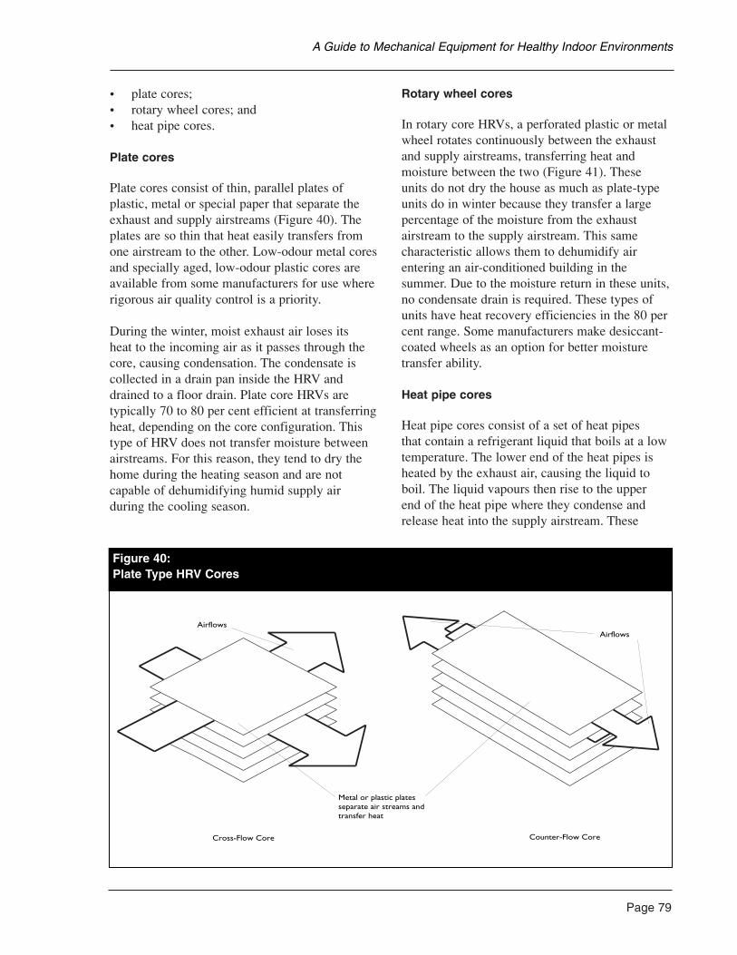
• plate cores; • rotary wheel cores; and• heat pipe cores.
Plate cores
Plate cores consist of thin, parallel plates ofplastic, metal or special paper that separate theexhaust and supply airstreams (Figure 40). Theplates are so thin that heat easily transfers fromone airstream to the other. Low-odour metal coresand specially aged, low-odour plastic cores areavailable from some manufacturers for use whererigorous air quality control is a priority.
During the winter, moist exhaust air loses its heat to the incoming air as it passes through thecore, causing condensation. The condensate iscollected in a drain pan inside the HRV anddrained to a floor drain. Plate core HRVs aretypically 70 to 80 per cent efficient at transferringheat, depending on the core configuration. Thistype of HRV does not transfer moisture betweenairstreams. For this reason, they tend to dry thehome during the heating season and are notcapable of dehumidifying humid supply air during the cooling season.
Rotary wheel cores
In rotary core HRVs, a perforated plastic or metalwheel rotates continuously between the exhaustand supply airstreams, transferring heat andmoisture between the two (Figure 41). These units do not dry the house as much as plate-typeunits do in winter because they transfer a largepercentage of the moisture from the exhaustairstream to the supply airstream. This samecharacteristic allows them to dehumidify airentering an air-conditioned building in thesummer. Due to the moisture return in these units,no condensate drain is required. These types ofunits have heat recovery efficiencies in the 80 percent range. Some manufacturers make desiccant-coated wheels as an option for better moisturetransfer ability.
Heat pipe cores
Heat pipe cores consist of a set of heat pipes that contain a refrigerant liquid that boils at a lowtemperature. The lower end of the heat pipes isheated by the exhaust air, causing the liquid toboil. The liquid vapours then rise to the upper end of the heat pipe where they condense andrelease heat into the supply airstream. These
Page 79
A Guide to Mechanical Equipment for Healthy Indoor Environments
Cross-Flow Core Counter-Flow Core
Airflows
Metal or plastic plates separate air streams and transfer heat
Airflows
Figure 40:Plate Type HRV Cores
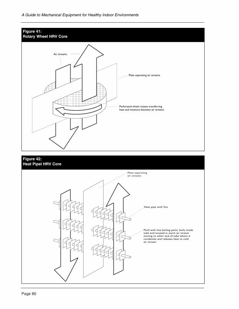
Page 80
A Guide to Mechanical Equipment for Healthy Indoor Environments
Air streams
Plate separating air streams
Perforated wheel rotates transferringheat and moisture between air streams
Figure 41:Rotary Wheel HRV Core
Heat pipe with fins
Fluid with low boiling point, boils insidetube end located in warm air streammoving to other end of tube where itcondenses and releases heat to coldair stream
Plate separatingair streams
Figure 42:Heat Pipel HRV Core
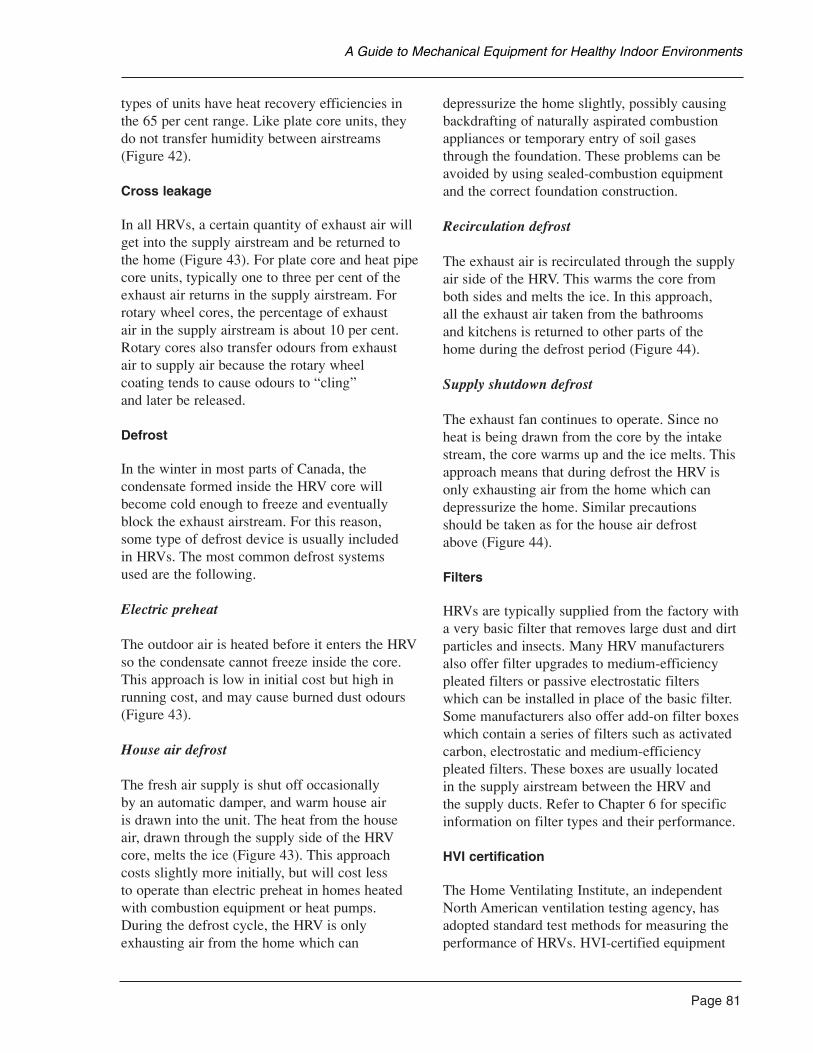
types of units have heat recovery efficiencies inthe 65 per cent range. Like plate core units, theydo not transfer humidity between airstreams(Figure 42).
Cross leakage
In all HRVs, a certain quantity of exhaust air willget into the supply airstream and be returned tothe home (Figure 43). For plate core and heat pipecore units, typically one to three per cent of theexhaust air returns in the supply airstream. Forrotary wheel cores, the percentage of exhaust air in the supply airstream is about 10 per cent.Rotary cores also transfer odours from exhaust air to supply air because the rotary wheel coating tends to cause odours to “cling” and later be released.
Defrost
In the winter in most parts of Canada, thecondensate formed inside the HRV core willbecome cold enough to freeze and eventuallyblock the exhaust airstream. For this reason, some type of defrost device is usually included in HRVs. The most common defrost systems used are the following.
Electric preheat
The outdoor air is heated before it enters the HRVso the condensate cannot freeze inside the core.This approach is low in initial cost but high inrunning cost, and may cause burned dust odours(Figure 43).
House air defrost
The fresh air supply is shut off occasionally by an automatic damper, and warm house air is drawn into the unit. The heat from the houseair, drawn through the supply side of the HRVcore, melts the ice (Figure 43). This approachcosts slightly more initially, but will cost less to operate than electric preheat in homes heatedwith combustion equipment or heat pumps.During the defrost cycle, the HRV is onlyexhausting air from the home which can
depressurize the home slightly, possibly causingbackdrafting of naturally aspirated combustionappliances or temporary entry of soil gasesthrough the foundation. These problems can beavoided by using sealed-combustion equipmentand the correct foundation construction.
Recirculation defrost
The exhaust air is recirculated through the supplyair side of the HRV. This warms the core fromboth sides and melts the ice. In this approach, all the exhaust air taken from the bathrooms and kitchens is returned to other parts of the home during the defrost period (Figure 44).
Supply shutdown defrost
The exhaust fan continues to operate. Since noheat is being drawn from the core by the intakestream, the core warms up and the ice melts. Thisapproach means that during defrost the HRV isonly exhausting air from the home which candepressurize the home. Similar precautions should be taken as for the house air defrost above (Figure 44).
Filters
HRVs are typically supplied from the factory witha very basic filter that removes large dust and dirtparticles and insects. Many HRV manufacturersalso offer filter upgrades to medium-efficiencypleated filters or passive electrostatic filters which can be installed in place of the basic filter.Some manufacturers also offer add-on filter boxeswhich contain a series of filters such as activatedcarbon, electrostatic and medium-efficiencypleated filters. These boxes are usually located in the supply airstream between the HRV and the supply ducts. Refer to Chapter 6 for specificinformation on filter types and their performance.
HVI certification
The Home Ventilating Institute, an independentNorth American ventilation testing agency, hasadopted standard test methods for measuring theperformance of HRVs. HVI-certified equipment
Page 81
A Guide to Mechanical Equipment for Healthy Indoor Environments
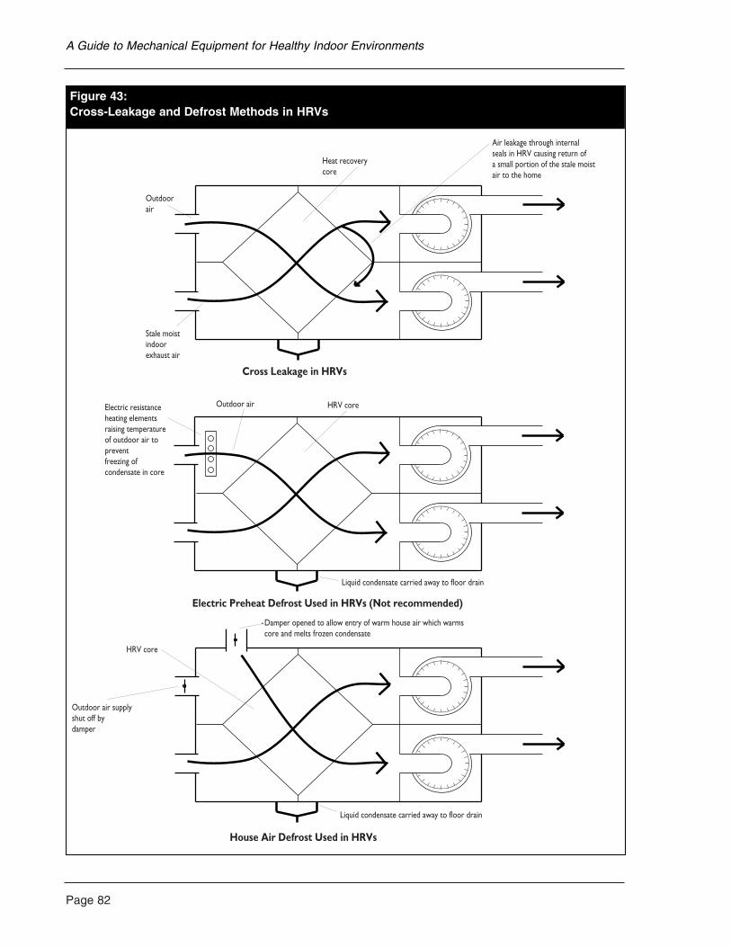
Page 82
A Guide to Mechanical Equipment for Healthy Indoor Environments
Figure 43:Cross Leakage and Defrost Methods in HRVs
Cross Leakage in HRVs
Electric Preheat Defrost Used in HRVs (Not recommended)
House Air Defrost Used in HRVs
Heat recoverycore
Stale moistindoorexhaust air
Outdoorair
Air leakage through internalseals in HRV causing return ofa small portion of the stale moistair to the home
Electric resistanceheating elementsraising temperatureof outdoor air topreventfreezing ofcondensate in core
Outdoor air HRV core
Liquid condensate carried away to floor drain
Damper opened to allow entry of warm house air which warmscore and melts frozen condensate
HRV core
Outdoor air supplyshut off bydamper
Liquid condensate carried away to floor drain
Figure 43:Cross-Leakage and Defrost Methods in HRVs
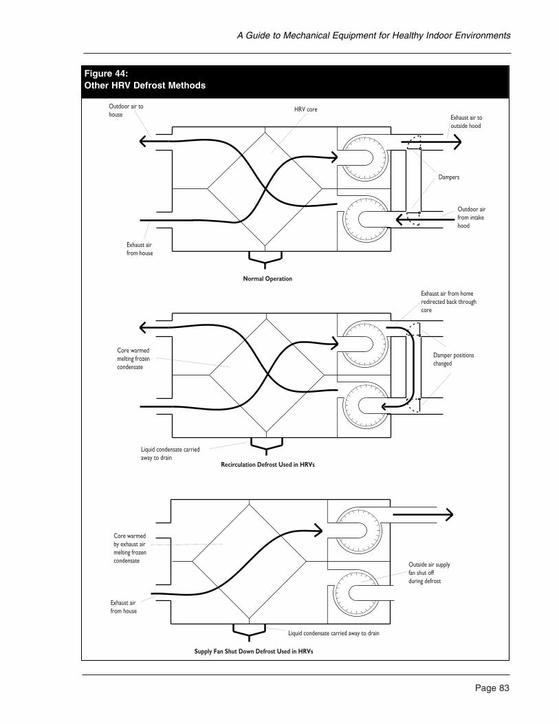
Page 83
A Guide to Mechanical Equipment for Healthy Indoor Environments
er HRV Defrost Methods
Normal Operation
Recirculation Defrost Used in HRVs
Supply Fan Shut Down Defrost Used in HRVs
Outdoor air tohouse
HRV core
Exhaust air from house
Dampers
Exhaust air tooutside hood
Outdoor airfrom intakehood
Liquid condensate carriedaway to drain
Core warmedmelting frozencondensate
Exhaust air from homeredirected back throughcore
Damper positionschanged
Liquid condensate carried away to drain
Core warmedby exhaust airmelting frozencondensate
Exhaust airfrom house
Outside air supplyfan shut offduring defrost
Figure 44:Other HRV Defrost Methods
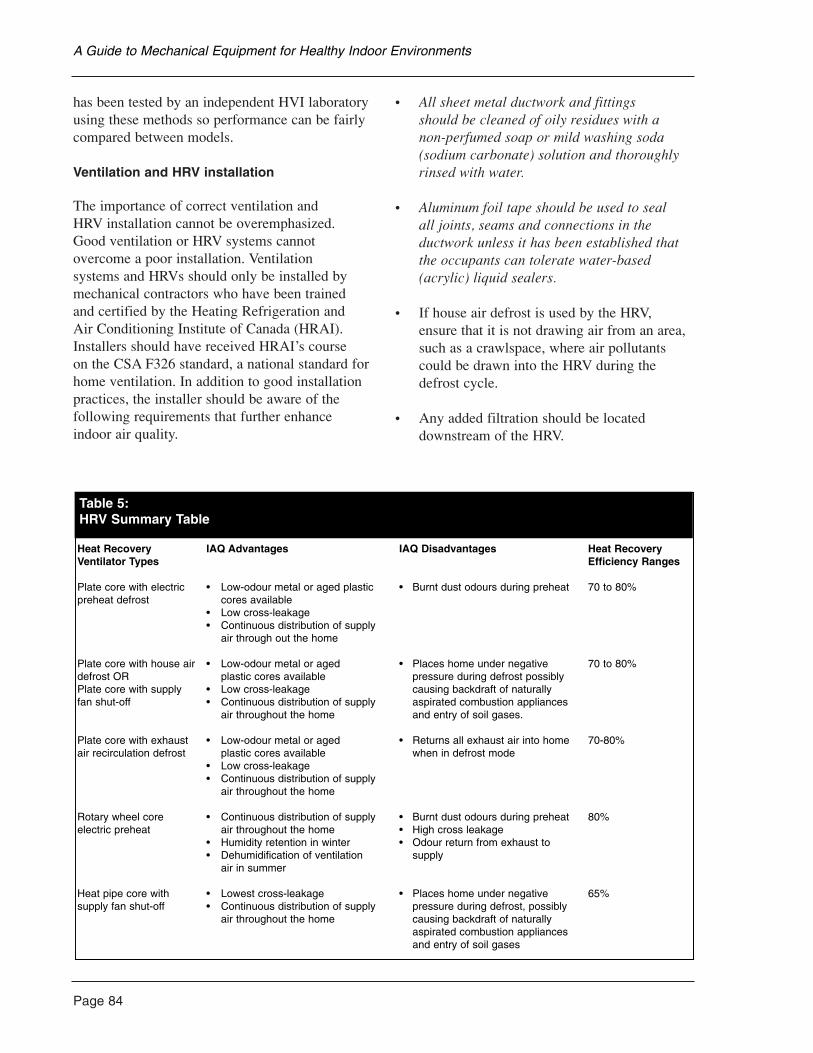
Page 84
has been tested by an independent HVI laboratoryusing these methods so performance can be fairlycompared between models.
Ventilation and HRV installation
The importance of correct ventilation and HRV installation cannot be overemphasized.Good ventilation or HRV systems cannotovercome a poor installation. Ventilation systems and HRVs should only be installed bymechanical contractors who have been trained and certified by the Heating Refrigeration and Air Conditioning Institute of Canada (HRAI).Installers should have received HRAI’s course on the CSA F326 standard, a national standard forhome ventilation. In addition to good installationpractices, the installer should be aware of thefollowing requirements that further enhanceindoor air quality.
• All sheet metal ductwork and fittings should be cleaned of oily residues with a non-perfumed soap or mild washing soda(sodium carbonate) solution and thoroughlyrinsed with water.
• Aluminum foil tape should be used to seal all joints, seams and connections in theductwork unless it has been established thatthe occupants can tolerate water-based(acrylic) liquid sealers.
• If house air defrost is used by the HRV,ensure that it is not drawing air from an area,such as a crawlspace, where air pollutantscould be drawn into the HRV during thedefrost cycle.
• Any added filtration should be locateddownstream of the HRV.
A Guide to Mechanical Equipment for Healthy Indoor Environments
Table 5:HRV Summary Table
Heat Recovery IAQ Advantages IAQ Disadvantages Heat Recovery Ventilator Types Efficiency Ranges
Plate core with electric • Low-odour metal or aged plastic • Burnt dust odours during preheat 70 to 80%preheat defrost cores available
• Low cross-leakage• Continuous distribution of supply
air through out the home
Plate core with house air • Low-odour metal or aged • Places home under negative 70 to 80%defrost OR plastic cores available pressure during defrost possibly Plate core with supply • Low cross-leakage causing backdraft of naturally fan shut-off • Continuous distribution of supply aspirated combustion appliances
air throughout the home and entry of soil gases.
Plate core with exhaust • Low-odour metal or aged • Returns all exhaust air into home 70-80%air recirculation defrost plastic cores available when in defrost mode
• Low cross-leakage• Continuous distribution of supply
air throughout the home
Rotary wheel core • Continuous distribution of supply • Burnt dust odours during preheat 80%electric preheat air throughout the home • High cross leakage
• Humidity retention in winter • Odour return from exhaust to • Dehumidification of ventilation supply
air in summer
Heat pipe core with • Lowest cross-leakage • Places home under negative 65%supply fan shut-off • Continuous distribution of supply pressure during defrost, possibly
air throughout the home causing backdraft of naturally aspirated combustion appliances and entry of soil gases
Maintenance
The filters and the core have to be periodicallycleaned. Clogged filters block the airflow andprovide a medium for microbial contaminants to grow.
Kitchen Range Exhaust (Outside Vented)
• Sheet metal hoods with grease filter and light.Fan may be in hood or remote-mounted.
• Downdraft exhaust is integrated with cooktop/grille units.
Other common names
• Range hood; and• downdraft cook top exhaust.
Typical system applications
Kitchen exhaust with any type of heating andventilation system.
Installation considerations and options
• Only outside vented units are effective;recirculating units are not recommended.
• Hood type units are more effective thandowndraft of the same capacity.
• Remote blowers are quieter. Location isflexible, but must allow access for repair,replacement and cleaning.
Health issues
Advantages
• Exhausting cooking odours and combustionproducts at source is an important air quality measure.
• High-capacity range exhausts with at least200 L/S (424 cfm) flow, with remote-mountedblower are preferred.
Disadvantages
• Large-capacity exhausts are incompatiblewith conventionally vented furnaces, waterheaters and fireplaces, especially in draft-sealed houses. Pressure relief or supply air provisions must be made.
General comments
Only electric cookers should be used by thehypersensitive. Recirculation kitchen rangeexhausts should not be used by the hypersensitive.
Maintenance requirements
Regular grease filter cleaning.
Operating cost/savings
Fan operation is inexpensive. Ventilation cost depends on heating system and otherventilation factors.
Product sources
• Ventilation and heating contractors; and• kitchen equipment suppliers.
See also the information on ventilationaccessories in this chapter.
Recirculating Central Ventilator
• A fan is installed in a box with exhaust ducts,a return duct, outside air intake and outsidedischarge. Air is mixed and recirculated by a baffle system.
• Primarily developed for moisture control.May incorporate basic filtration.
Other common names
RCV.
Page 85
A Guide to Mechanical Equipment for Healthy Indoor Environments
Page 86
Typical system applications
For bathroom, kitchen and laundry exhaust with any type of heating system. Some supply air capacity.
Installation considerations and options
Located similar to CEV or HRV in attic or basement.
Health issues
Advantages
• Can provide adequate exhaust capacity formoisture control.
Disadvantages
• Outside air capacity is limited and notadequate for full ventilation requirements.
• Recirculating house air retains pollutants andmixes odours between rooms.
General comments
RCVs do not provide a complete ventilationsystem for the home, but are appropriate forsingle rooms or as recirculation fans for use inside the home.
Maintenance requirements
Occasional checks and cleaning.
Operating cost/savings
Similar to other exhaust-only systems. Fanoperation is inexpensive but RCVs have no ability to recover heating energy.
Product sources
• Heating and ventilation contractors; and• equipment manufacturers.
See also the information in this chapter onventilation accessories.
Supplementary Ventilation AirFiltration for HRVs
Additional particulate and possibly odour removalfilters are installed in a sheet metal box connectedto a supply air duct. The increased resistance toairflow from having additional filter media shouldbe corrected by proper sizing of the HRV.
Other common names
• Medium-efficiency filters;• electrostatic filters; and• odour removal filters.
Typical system applications
Supply air filters for HRVs where outdoor air iscontaminated. See Chapter 6 for filter details.
Installation considerations and options
• Large filters must be used to minimize restriction.
• Access required for easy filter changes.
• Some reduction in ventilation airflow shouldbe expected.
Health issues
Advantages
• Can improve quality of air by reducingcontaminants such as pollens, someautomobile and industrial pollution,agricultural odours, etc.
Disadvantages
• One pass operation only. Must be effective filters.
• Will restrict airflow.
A Guide to Mechanical Equipment for Healthy Indoor Environments
General comments
• Minimum filter size is 300 mm x 300 mm x25 mm (12 in. x 12 in. x 1 in.). Larger filtersare preferred.
• Filter should fit tightly in housing to avoid bypassing.
Maintenance requirements
Periodic filter changes.
Product sources
• Ventilation and heating contractors; and• specialty filtration suppliers.
See also the information on air filtration inChapter 6.
Registers, Grilles and Diffusers
• Hard plastic (usually PVC) molded units.
• Steel units.
Other common names
Registers.
Typical system applications
Supply exhaust and return points for CEV, RCVand HRV systems.
Installation considerations and options
• Press-fitted into duct end or sealed with foil tape.
• A unique unit allows temporary full openingfor high-exhaust capacity.
• Motorized damper and humidity-actuatedunits available.
Health issues
Advantages
• Metal units are preferable to the hypersensitive.
Disadvantages
• May contain gaskets and seals which have anodour to the hypersensitive.
General comments
Metal units are usually painted. If paint odour is aproblem, plated (brass, chrome and stainless steel)units are available, usually from commercialequipment suppliers.
Maintenance requirements
None.
Product sources
• Ventilation and heating contractors; and• specialty ventilation suppliers.
See also the information on air filtration inChapter 6.
Page 87
A Guide to Mechanical Equipment for Healthy Indoor Environments
Page 88
Adapting the Warm-Air Furnace
Before modifying an existing furnace, theremaining lifetime of the furnace should beconsidered. The actual costs and benefits ofreplacing it with a more suitable model or aspecially designed air handling system shouldthen be compared. Often, a new furnace orheating system will result in lower energy costs due to higher-efficiency burners and motors. These will eventually offset some of theinvestment, typically in five to 15 years. The gasor electric utility, or fuel supplier will often havefinancing options available at favourable rates thatcan help to pay for replacement equipment.
If the furnace is fuel-fired, it should be checkedfor back venting and heat-exchanger conditionbefore undertaking any significant work on thesystem. Any problems should be corrected, and if major problems are encountered, the furnaceshould be replaced with a more suitable model.
Because a furnace is certified for safety by acertification agency, there are few changes thatcan be made to the furnace without voiding thesafety certification. Major changes are simply not permitted. Any modifications carried out to afurnace must be undertaken by a person with theappropriate fuel-safety or electrical qualifications.
Continuous blower operation
If the furnace fan is to be operated continuouslyfor ventilation or filtration reasons, a fan-onlyswitch is frequently added. Often, in older, belt-drive equipment, only one speed will be available.High-speed operation may cause discomfortproblems during the cold season while the burneris not operating, but will generally be acceptableduring milder weather. If a second speed isrequired, the single-speed motor can usually bereplaced. When electrical costs are considered,continuous low-speed operation is also less costlyto operate than high speed. If a direct-drive motoris installed, a lower speed can likely be provided
for continuous operation through wiring changes.Conversion to two-speed operation will requirethe installation of a fan control relay on many furnaces.
Burner delay for oil furnaces
Older oil furnaces tend to backdraft gases into the home, particularly when the chimney is cold,because the burner starts before a reliable drafthas been established. A simple modification toreduce this problem is to add a solenoid valvedelay unit to the burner. This device prevents oil from being injected into the burner until theburner blower has run for a short time and theflue draft has been more reliably established.These must be installed by a qualified burnerservice technician.
Blower motor replacement (belt drive motors)
If the furnace has a belt-drive fan, the motor may be replaced with a totally enclosed, fan-cooled (TEFC) motor. The advantage of a TEFCmotor is that the internal parts and windings arenot exposed to the recirculating airstream. Thisavoids the contribution of contaminants fromlubricating oils and motor insulation to theairstream. The housing and external parts of the new motor should be washed thoroughlybefore installation with a solution of washingsoda (sodium carbonate) and warm water toremove any oil and grease. Unfortunately, totallyenclosed replacement motors are not available for direct drive blowers.
If high-performance filtration or air conditioningare to be added to an older, forced air system, anew, more powerful fan motor may be required to overcome the added airflow resistance of these components.
Ductwork improvements
Typically, conventional ductwork installationshave many air leaks often located in areas where
5. HEATING AND VENTILATION SYSTEM RETROFITS
contaminants may be picked up and circulatedthroughout the house. Return air ducts located incrawlspaces or damp and unconditioned basementareas are of particular concern, since they oftendraw contaminated air into the occupied areas. Air leaks into return air ducts can also cause localdepressurization in the rooms where the furnaceand water heater are located. Depressurization cancause increased soil gas entry and combustion gasspillage from the furnace or water heater.
Ductwork should be carefully sealed usingaluminum foil tape or water-based liquid ductsealer (tested to be acceptable to the homeoccupants). Sealing should be carried out on thereturn air ductwork as a first priority, beginning at the furnace and working back toward thegrilles. Particular attention should be paid to the point at which the main return air trunk isjoined to any joist cavities which form return air branches. In some cases, particularly in olderhomes, joist cavities should be opened and linedwith sheet metal to reduce dust pickup andfiltering through from floors above, and to makeducts easier to clean. In older homes which havehad insulation blown into the wall, the return airsystem should be carefully checked to see thatinsulation is not being drawn from walls into joist cavities that are used as return paths.
Adding air conditioning
In houses with forced air systems, the mostcommon approach for adding air conditioning isto install a coil connected to an air conditioner orheat pump in the central forced air furnace. Thecompressor and condenser are typically mountedin an outdoor unit. The evaporator coil is mountedin the furnace plenum and is fed by refrigerantlines from the compressor. See Chapter 3 formore information.
In houses without forced air systems or where it is not appropriate to operate the forced airsystem continuously, local air conditioners maybe installed in specific rooms. The simplest ofthese is the basic window or wall-mounted airconditioner, though better-quality units are alsoavailable. See Chapter 3 for more information.
Furnace replacement
If a decision is made to replace a furnace, the requirements for the replacement unit should be considered carefully. Should a furnace replacement be desirable, a quality, heat loss calculation should be performed and an authorized worksheet or computer printoutshould be presented to the homeowner. The ideal replacement system for forced air systems,where air quality is a high priority, is often abuilt-up system that contains the following basic components:
• a blower with a TEFC motor isolated fromthe airstream;
• a high-performance filter unit;• a low-temperature heating coil supplied by a
remote heat pump, sealed combustion boileror water heater; and
• a cooling coil (if required) supplied by aremote heat pump or chiller unit (Figure 45).
A gas-fired domestic water heater with a fan-coil furnace attached is now available in Canada.This combined unit simplifies installation and has most of the features mentioned above. Thistype of system can have significant energy andoperating cost benefits. Such a system may also include special filter units for removinggaseous air pollutants if required (see Chapter 6).Accurate sizing of the water heater is critical. Themaximum legal limit for domestic water heaters is 60°C (140° F); therefore, the heat exchangermust be calculated at this temperature. Should the design water temperature be selected anyhigher than 60°C, not only will the residencereceive inadequate heating, but there will also be problems maintaining a supply of domestic hot water.
Modifying electric baseboard heating systems
The first decision to be made regarding electric baseboard heating is whether or not thebaseboards will be kept. If the baseboards are tobe kept, the ventilation, air filtration and other airtreatment will typically be added locally, ratherthan as part of a central system. If there is enough
Page 89
A Guide to Mechanical Equipment for Healthy Indoor Environments
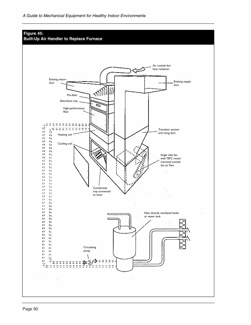
Page 90
A Guide to Mechanical Equipment for Healthy Indoor Environments
Figure 45:Built-Up Air Handler to Replace Furnace
Air outside fan/heat reclaimer
Existing supplyduct
Transition section and rising duct
New directly ventilated boileror water tank
Circulatingpump
Condensatetray connectedto drain
Cooling coil
Heating coil
Pre-filter
Absorbent tray
High-performancefilter
Existing returnduct
Single inlet fanwith TEFC motormounted outsidethe air flow
access for ducts, HRVs and air conditionersserving a few rooms are a common solution. Theaddition of a central ventilation system can alsobe done. However, if the baseboard heaters are asource of air quality complaints, due to their highsurface temperatures and subsequent charring ofdust particles, then they should be replaced. As an intermediate solution, they may be replacedwith lower-watt-density units. The leastexpensive, lower-watt-density units are thosestandard electric models with lower capacityelements for their length. Liquid-filled electricbaseboard heaters are a more costly option, butwith other advantages.
Adding low-temperature radiant heating
Radiant heating may sometimes be added toceilings or walls in existing houses by placing it over existing surfaces. Floor installation ofelectric radiant heating may also be done byremoving the ceiling below the room to be heated and applying hot water tubing to theunderside of the floor above. However, this is an inefficient system so tubing with aluminumfins is sometimes used to improve heat transfer.Insulation is then placed in the cavity between the tubing and the ceiling below, and the ceiling is replaced. Radiant electric heat elements or matsmay also be applied directly to an existing floor.For hydronic radiant heat, polybutylene or cross-linked polyethylene tubing is placed on theoriginal floor and covered with a thin layer of concrete, lightweight concrete or gypsumconcrete. A new finish floor will then be requiredon top of the heating system. This approach willresult in a floor height difference between theroom being heated and other rooms in the house,unless they are also converted. See Chapter 3 fora further discussion of these systems.
Adding ventilation and filtration equipment
If exhaust-only ventilation is added to the wholehouse, there is no assurance that individual roomswill receive sufficient ventilation at all times,even if they are equipped with a wall-inlet slot. To ensure adequate ventilation air distribution, an RCV or recirculation system should be
installed. Typically, such a fan would remove air from the bath and closet locations and supplythe air to the living areas of the house such as the bedrooms and living room. Exhaust points aretypically located in kitchens and washrooms. Therate of air withdrawal or supply for a recirculationsystem should be at least 10 L/S (20 cfm) for asingle bedroom and 20 L/S (40 cfm) for a masterbedroom. Higher airflow rates provide betterperformance. See Chapter 4 for further discussion.
An HRV may be equipped with high-performancefilters to treat incoming air fairly effectively.RCVs are usually more limited in filtrationcapacity. A portable or single-room filtration unit is one option, especially in sanctuary rooms. If air conditioning is added in the form of a window unit or mini split air conditioner,some filtering may be adapted. A mini split airconditioning unit can be operated continuouslyfor filtration with less noise than a window unit.See Chapter 6 for more details.
Houses without a forced air system
For houses without a central forced air heatingsystem or where it is not appropriate to operatethe heating system continuously, ventilation maybe provided by an RCV serving a single room or a wider area of the house. Higher-quality andhigher-volume ventilation may be provided by an HRV. Fresh air should be delivered directly to sleeping areas and may be removed fromsecondary areas such as washrooms or closets.See Chapter 4 for more details.
Houses with a forced air system
For houses where a central forced air system exists and it is appropriate to operate itcontinuously, some ventilation may be providedby installing a duct from the outside, connected tothe return air plenum of the furnace. Care shouldbe taken when installing this duct that the airflowquantity is not too large (Figure 46). Excessiveairflow can lead to discomfort and prematurefailure of some furnace components. However,the ventilation that may be provided in this way
Page 91
A Guide to Mechanical Equipment for Healthy Indoor Environments
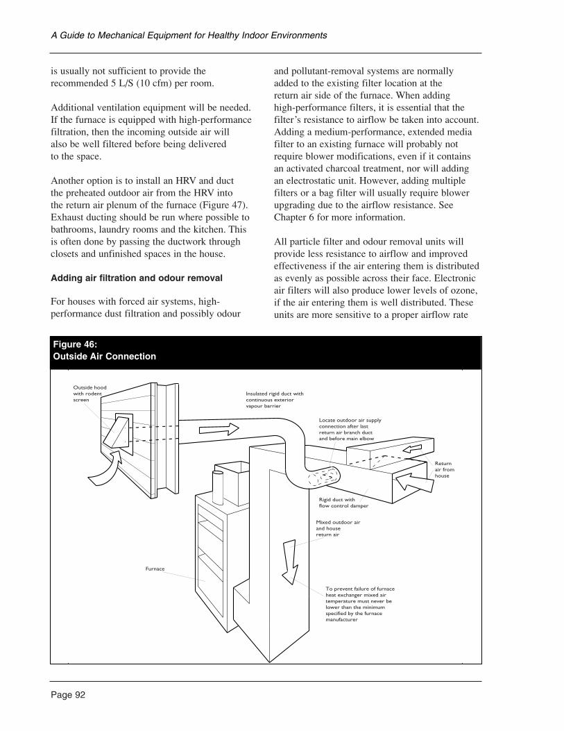
Page 92
is usually not sufficient to provide therecommended 5 L/S (10 cfm) per room.
Additional ventilation equipment will be needed.If the furnace is equipped with high-performancefiltration, then the incoming outside air will also be well filtered before being delivered to the space.
Another option is to install an HRV and duct the preheated outdoor air from the HRV into the return air plenum of the furnace (Figure 47).Exhaust ducting should be run where possible tobathrooms, laundry rooms and the kitchen. This is often done by passing the ductwork throughclosets and unfinished spaces in the house.
Adding air filtration and odour removal
For houses with forced air systems, high-performance dust filtration and possibly odour
and pollutant-removal systems are normallyadded to the existing filter location at the return air side of the furnace. When adding high-performance filters, it is essential that thefilter’s resistance to airflow be taken into account.Adding a medium-performance, extended mediafilter to an existing furnace will probably notrequire blower modifications, even if it containsan activated charcoal treatment, nor will addingan electrostatic unit. However, adding multiplefilters or a bag filter will usually require blowerupgrading due to the airflow resistance. SeeChapter 6 for more information.
All particle filter and odour removal units willprovide less resistance to airflow and improvedeffectiveness if the air entering them is distributedas evenly as possible across their face. Electronicair filters will also produce lower levels of ozone,if the air entering them is well distributed. Theseunits are more sensitive to a proper airflow rate
A Guide to Mechanical Equipment for Healthy Indoor Environments
Outside hoodwith rodentscreen
Furnace
Mixed outdoor airand housereturn air
To prevent failure of furnaceheat exchanger mixed airtemperature must never belower than the minimumspecified by the furnacemanufacturer
Rigid duct withflow control damper
Returnair fromhouse
Locate outdoor air supplyconnection after lastreturn air branch ductand before main elbow
Insulated rigid duct withcontinuous exteriorvapour barrier
Figure 46:Outside Air Connection
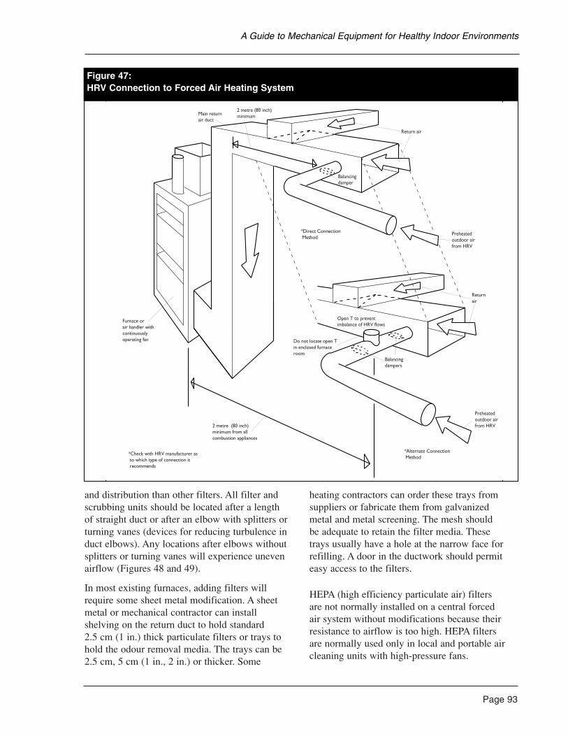
and distribution than other filters. All filter andscrubbing units should be located after a length of straight duct or after an elbow with splitters orturning vanes (devices for reducing turbulence induct elbows). Any locations after elbows withoutsplitters or turning vanes will experience unevenairflow (Figures 48 and 49).
In most existing furnaces, adding filters willrequire some sheet metal modification. A sheetmetal or mechanical contractor can installshelving on the return duct to hold standard 2.5 cm (1 in.) thick particulate filters or trays tohold the odour removal media. The trays can be2.5 cm, 5 cm (1 in., 2 in.) or thicker. Some
heating contractors can order these trays fromsuppliers or fabricate them from galvanized metal and metal screening. The mesh should be adequate to retain the filter media. These trays usually have a hole at the narrow face forrefilling. A door in the ductwork should permiteasy access to the filters.
HEPA (high efficiency particulate air) filters are not normally installed on a central forced air system without modifications because theirresistance to airflow is too high. HEPA filters are normally used only in local and portable aircleaning units with high-pressure fans.
Page 93
A Guide to Mechanical Equipment for Healthy Indoor Environments
Figure 47:HRV Connection to Forced Air Heating System
Main returnair duct
2 metre (80 inch)minimum
Return air
Balancingdamper
Preheatedoutdoor airfrom HRV
*Direct Connection Method
Returnair
Balancingdampers
Open T to preventimbalance of HRV flows
Preheatedoutdoor airfrom HRV
*Alternate Connection Method
Do not locate open Tin enclosed furnaceroom
2 metre (80 inch)minimum from allcombustion appliances
*Check with HRV manufacturer as to which type of connection it recommends
Furnace orair handler withcontinuouslyoperating fan
Figure 47:HRV Connection to Forced Air Heating System
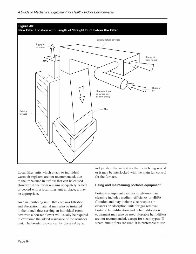
Page 94
Local filter units which attach to individual warm air registers are not recommended, due to the imbalance in airflow that can be caused.However, if the room remains adequately heatedor cooled with a local filter unit in place, it maybe appropriate.
An “air scrubbing unit” that contains filtration and absorption material may also be installed in the branch duct serving an individual room;however, a booster blower will usually be requiredto overcome the added resistance of the scrubberunit. The booster blower can be operated by an
independent thermostat for the room being servedor it may be interlocked with the main fan controlfor the furnace.
Using and maintaining portable equipment
Portable equipment used for single-room aircleaning includes medium-efficiency or HEPAfiltration and may include electrostatic aircleaners or adsorption units for gas removal.Portable humidification and dehumidificationequipment may also be used. Portable humidifiersare not recommended, except for steam types. Ifsteam humidifiers are used, it is preferable to use
A Guide to Mechanical Equipment for Healthy Indoor Environments
Existing return air duct
Return air from house
OutdoorairNew transition
to spread out air flow evenly
New filterExistingfurnace
Supply airto house
Figure 48:New Filter Location with Length of Straight Duct before the Filter
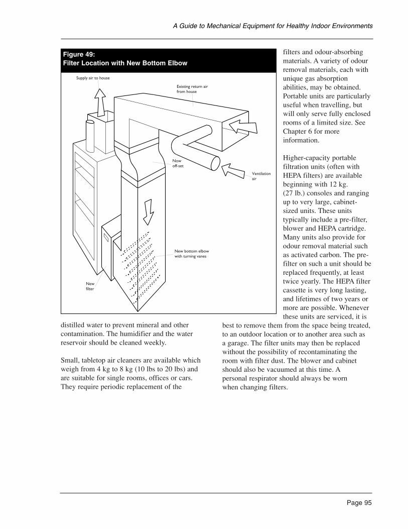
distilled water to prevent mineral and othercontamination. The humidifier and the waterreservoir should be cleaned weekly.
Small, tabletop air cleaners are available whichweigh from 4 kg to 8 kg (10 lbs to 20 lbs) and are suitable for single rooms, offices or cars. They require periodic replacement of the
filters and odour-absorbingmaterials. A variety of odourremoval materials, each withunique gas absorptionabilities, may be obtained.Portable units are particularlyuseful when travelling, butwill only serve fully enclosedrooms of a limited size. SeeChapter 6 for moreinformation.
Higher-capacity portablefiltration units (often withHEPA filters) are availablebeginning with 12 kg. (27 lb.) consoles and rangingup to very large, cabinet-sized units. These unitstypically include a pre-filter,blower and HEPA cartridge.Many units also provide forodour removal material suchas activated carbon. The pre-filter on such a unit should bereplaced frequently, at leasttwice yearly. The HEPA filtercassette is very long lasting,and lifetimes of two years ormore are possible. Wheneverthese units are serviced, it is
best to remove them from the space being treated,to an outdoor location or to another area such as a garage. The filter units may then be replacedwithout the possibility of recontaminating theroom with filter dust. The blower and cabinetshould also be vacuumed at this time. Apersonal respirator should always be worn when changing filters.
Page 95
A Guide to Mechanical Equipment for Healthy Indoor Environments
Supply air to house
Existing return airfrom house
Ventilationair
Nowoff-set
New bottom elbowwith turning vanes
Newfilter
Figure 49:Filter Location with New Bottom Elbow
Page 96
The Purpose of Filtration
Air filtration is usually incorporated into a forced air system to remove contaminants in theair supplied to occupants. Homes with other typesof heating usually have no filtration. Filtrationmay also be incorporated into a ventilation systemor sometimes into special systems which filterrecirculating air.
Basic air filtration reduces the quantity ofparticulates (dust, particles, pollens, molds)suspended in the air of the home. This isimportant to reduce:
• the quantity of particulates which are likely to be inhaled;
• the need for housecleaning and furnace duct cleaning;
• the quantity of particulates reaching hotsurfaces in heating systems;
• the accumulation of dust on moist surfaceswhich can support microbial growth; and
• inhalants that may aggravate or cause allergicor asthmatic reactions.
It also protects the heating, air conditioning andventilation equipment.
House dust is a mixture of fine and coarse particlesfrom many sources including allergenic fungi,animal dander, pollens, mineral fibres, soot, metalaerosols and particles devolving from the decayprocess of some airborne organic compounds.
Fine particles (below 20 microns in diameter) arenot visible without magnification and are normallymeasured as:
• PM10 Particulate Matter below 10 micron(also referred to as Inhalable SuspendedParticulates, or ISP).
• PM2.5 Particulate Matter below 2.5 micron(also referred to as Respirable SuspendedParticulate, or RSP).
Respirable Suspended Particulate (PM2.5) are thosewhich will travel deeply into the respiratory tract.Some of these particles may enter directly into thebloodstream. Particles between 2.5 and 10 microndiameter do not usually penetrate deeply into therespiratory tract and tend to lodge in the upperrespiratory tract and upper air passageways.Particles larger than the PM10 cut point are notgenerally breathed in by persons during ordinaryactivities.
In the absence of filtration, particles larger than 5 micron settle out of the air by gravity and verysmall particles of less than 1 micron diameter areremoved by electromagnetic forces and other,non-gravitational forces. Particles between 1 and5 micron diameter are removed by a combinationof gravity and the non-gravitational forces.
When there is no activity in a room or space,all particles tend to settle out within a matter of hours. Whenever there is activity however,particles are re-suspended from the surfaces in the room. Certain activities such as vacuumingmay re-suspend very large amounts of particles.Other activities, such as cooking, may generateparticles. A filter located in a central warm-airfurnace will not have a very large effect on theamount of dust breathed in by the occupantsduring periods of activity, but over time, mayreduce the total amount of dust in the home whichis available for re-suspension. An in-room airfilter will have a similar effect, varying accordingto the size and airflow of the filter relative to thesize of the room. For all houses, and in particularfor houses which do not have central, forced-airheating or cooling systems, careful andcontinuous cleaning of surfaces is an importantmethod of controlling dust.
Where there is an outdoor-air ventilation system,and where pollens or dust from outdoor sourcesmay be a problem, a system of air filtration forthe incoming air is very important.
6. FILTRATION AND AIR CLEANING SYSTEMS
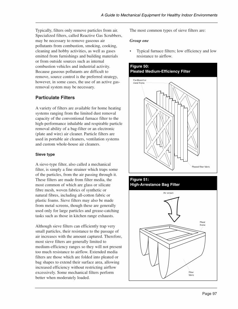
Typically, filters only remove particles from air.Specialized filters, called Reactive Gas Scrubbers,may be necessary to remove gaseous airpollutants from combustion, smoking, cooking,cleaning and hobby activities, as well as gasesemitted from furnishings and building materialsor from outside sources such as internalcombustion vehicles and industrial activity.Because gaseous pollutants are difficult toremove, source control is the preferred strategy,however, in some cases, the use of an active gas-removal system may be necessary.
Particulate Filters
A variety of filters are available for home heatingsystems ranging from the limited dust removalcapacity of the conventional furnace filter to thehigh-performance inhalable and respirable particleremoval ability of a bag-filter or an electronic(plate and wire) air cleaner. Particle filters areused in portable air cleaners, ventilation systemsand custom whole-house air cleaners.
Sieve type
A sieve-type filter, also called a mechanical filter, is simply a fine strainer which traps some of the particles, from the air passing through it.These filters are made from filter media, the most common of which are glass or silicate fibre mesh, woven fabrics of synthetic or natural fibres, including all-cotton fabric or plastic foams. Sieve filters may also be madefrom metal screens, though these are generallyused only for large particles and grease-catchingtasks such as those in kitchen range exhausts.
Although sieve filters can efficiently trap verysmall particles, their resistance to the passage ofair increases with the amount captured. Therefore,most sieve filters are generally limited tomedium-efficiency ranges so they will not presenttoo much resistance to airflow. Extended mediafilters are those which are folded into pleated orbag shapes to extend their surface area, allowingincreased efficiency without restricting airflowexcessively. Some mechanical filters performbetter when moderately loaded.
The most common types of sieve filters are:
Group one
• Typical furnace filters; low efficiency and lowresistance to airflow.
Page 97
A Guide to Mechanical Equipment for Healthy Indoor Environments
Cardboard or metal frame
Pleated filter fabric
Figure 50:Pleated Medium-Efficiency Filter
Air stream
Metalframe
Filterfabric
Figure 51:High-Arrestance Bag Filter
Page 98
• Useful only for coarse filtration to protectequipment, and pre-filtering to protect finerfilters and gas removal filters.
• Traps textile fibres, hair and coarse dustgreater than 10 microns.
Groups one and two
• Pleated, extended media; medium efficiencyand low to medium resistance to airflow.
• Commonly used as a furnace filter upgrade,or in air cleaners.
• Traps some pollens, animal dander, fungalspores and fine soil particles in the fivemicron range (Figure 50).
Group two
• Bag-type, extended media; medium to highefficiency and medium to high resistance toairflow.
• Commonly used in special air cleaningsystems, portable filters and with fan-coil,forced air systems equipped with highpressure fans.
• A wide range of efficiencies are available. These are capable of trapping pollens, fungalspores, fine soil and some bacteria in the onemicron range (Figure 51).
Group three
• Extended media; very high efficiency andvery high resistance to airflow.
• Commonly used in hospital and industrialclean-room situations and occasionally inhigh-performance portable air cleaners orcustom filter systems.
• HEPA grade is capable of trapping bacteria aswell as other fine particles and has a minimumparticle removal efficiency of 99.97% at 0.3micron and larger when tested according tothe D.O.P. (di-octyl phthalate) test method.
Filter efficiency for trapping small particles is notonly a function of the size of the openings in thefilter, but also of materials with which it may becoated. For example, some sieve filters may havea coating which aids in trapping fine dust. (Seethe information on filter coatings in this chapter.)As the filter becomes loaded with dust, itsefficiency for trapping small particles thenimproves because it is less porous.
Electrostatic filters
The principle behind electrostatic filters is thatdust particles which become electrically chargedmay be attracted to collection plates, screens orpads. The three distinct types are: PassiveElectrostatic, Charged Media and Electronic(Plate and Wire). Unlike disposable filters, mosttypes of electrostatic filers are semi-permanent,requiring only periodic cleaning and washing toremove accumulated dust. Some charged padfilters require replacement of the pad element.
Passive electrostatic filters
These units use grids of fine, polypropylenestrands with or without a polyester sheet betweenthe grids. These retain a small static electricalcharge which is renewed by the movement of air over them. Charged dust particles passingthrough the grid tend to stick to the strands. These are commonly used as retrofit furnacefilters and in portable air cleaners. They use noelectricity and produce no ozone gas.
Charged media filters
These filters consist of two screens betweenwhich a pad is sandwiched. The first screenimparts a charge to the incoming particles and the second screen imparts an opposite charge to the pad. Performance is very similar to passiveelectrostatic filters. Pads may require periodicchanging and may only be available from themanufacturer.
A Guide to Mechanical Equipment for Healthy Indoor Environments
Electronic (Plate and Wire) filters
The electronic filter works by a similar principle,but the grids are made from metal wires or finswhich are charged by a high-voltage electricalsupply. This type of filter was found to be themost effective at respirable/inhalable particleremoval in field testing by CMHC. Unfortunately,these filters also produce small amounts of ozone,an irritating gas. Ozone can affect asthmatics andthose with severe respiratory sensitivity. Theseunits also produce a characteristic crackling orpopping noise.
Turbulent flow precipitator
Turbulent flow precipitator (TFP) is a new type of filter which can remove particles as smallas 0.1 micron. Particles are separated from theairstream by means of a turbulent airflow. Theperformance of the unit is not affected by theloading since the air particles are captured in aseparate compartment. For residential use, thesefilters require a booster fan and are not able tohandle the full flow of a typical central forced airheating and cooling system. For this reason, theyare installed in a bypass configuration or as in-room,portable units.
Ion generators
Air ionization is the process of altering theelectrical charge on gas molecules in the air.
Though generally thought of as an odour controlmethod or a means of enhancing a feeling of well-being through altering ion balance, ionization hasalso been used for particulate removal. Some verysmall particles are maintained suspended in airbecause they carry static electric charges whichcause them to be repelled by walls and floors.These are difficult to trap with conventional airfilters. An ion generator produces ions which alterthe charge on particles, which in turn, alter otherparticles nearby. In theory, suspended particleswhich have had their charge altered tend to fall tothe floor where they can be removed by cleaning.This effect is not well proven.
The use of ionization for odour control and enhancedwell-being, discussed later in this chapter underother special considerations, should be distinguishedfrom its use for particle removal.
Filter performance
Currently, there are four generally acceptedmeasures of filter performance which areapplicable to residential type filters:• Arrestance• Atmospheric (Dust Spot) Efficiency• D.O.P. Efficiency• Clean Air Delivery
Arrestance is a result of the Arrestance test cyclecarried out according to the ASHRAE Standard52.1. This test is useful for rating filters for theirability to filter particles in the coarse, visiblerange, but is not useful for rating filters for theirability to remove respirable or inhalable particlesfrom the airstream. Group one filters are usuallyrated by this method. The Arrestance value can be quite high (90%) for a filter which has onlymediocre performance (10 to 20%) in removinginhalable and respirable dust. Arrestance is oftenquoted by suppliers of filtration products as"Efficiency" because it is expressed as a % removalvalue. This practice is misleading, tending togrossly over-represent the ability of the filter toremove particles in the inhalable/respirable range.
Atmospheric Efficiency is the result of theAtmospheric Dust Spot Test Method carried outaccording to ASHRAE Standard 52.1. This test isuseful for rating filters in the inhalable/respirabledust range. Pleated fabric filters of the group twotype are rated at about 20 to 30% atmosphericefficiency. Group three bag filters can haveratings between 30 and 70% according to thismethod.
D.O.P. Efficiency is the result of a specific testwhich measures the ability of the filter to removeparticles of 0.3 micron and larger. The test isrelevant for High Efficiency Particulate Air(HEPA) filters which must achieve a value of99.97% removal effectiveness according to thistest in order to be classified as HEPA filters. Thebest of the Group three filters, high performancebags and electronics are rated at about 10 to 30%
Page 99
A Guide to Mechanical Equipment for Healthy Indoor Environments
Page 100
D.O.P efficiency.Clean Air Delivery Rate is the reported parameterfor portable air cleaners tested by the AmericanHome Appliance Manufacturer's Association(AHAM). Conceptually, the Clean Air DeliveryRate (CADR) is the flow rate of perfectly cleanair which would be required to produce theequivalent effect of the air cleaning device inquestion. This allows comparison of two unitswith different airflows and efficiencies. For example,a unit may have an airflow of 100 L/s and anefficiency of 50%, so the CADR is 50 L/s. Anotherunit may have an airflow of 200 L/s and anefficiency of 25% but will also have a CADR of 50 L/s.
Typical medium-efficiency filters for home useshould be about 30% atmospheric efficiency. Thisis the minimum recommendation forenvironmentally hypersensitive applications. Ifhigh performance filters are desired they shouldbe rated at 60% atmospheric. Very highperformance filters of up to 85% atmospheric maybe used, however these filters may require specialmodifications to a conventional forced air systemin order to accommodate the higher resistance toairflow.
Odour removal
Removal of gases from air requires differentmethods than particle removal and differentequipment. There are two methods which can be used: adsorption and reactive scrubbing.Unlike sieve filters which differ mainly in theirefficiency at trapping particles of a certain size,adsorption and reactive scrubbing materials mustbe specifically selected for the gases they areintended to remove. Some of the importantvariables, among the hundreds of gases which can be trapped, are the size of the gas molecule,its reactivity and its ability to form acids or alkalis.
Gaseous adsorbers
An adsorption material is one which containsmicroscopic pores or surface irregularities able to trap molecules of gases on its surfaces wherethey can be held until disposed. Activated carbonand crystalline zeolite are common types of
adsorbent material.
• Activated carbon (charcoal), the mostcommon and broadly effective gas adsorptionmaterial, is effective for many solvent odours,diesel and other fuels, alcohol odours, bodyand bathroom odours, cooking, dry cleaning,paint and adhesive odours, and pet odours. It is not highly effective for formaldehyde,ammonia and some irritating components of urban smog, such as sulphur and nitrogenoxides. Generally, it is least effective forcompounds with low molecular weight.Activated carbon is usually made from wood, coconut shell or peat.
• Zeolite, mined from mineral deposits, isparticularly effective for ammonia odoursfrom pets and urine spills. Generally, it ismost effective for compounds which arealkaline. Zeolite is not a substitute for carbon for general odour removal purposes,but can be an important supplement.
Adsorption filters will usually collect moisturequite readily and begin to deteriorate if used indamp locations. They should only be used in adry airstream which is relatively free of particlesand oily substances.
Reactive scrubbers
Reactive scrubbers actually react chemically with gases and render them inert or stable until they can be disposed. These are also called absorbers. Potassium permanganate on a base of activated alumina is a common type of reactive scrubber material.
• Potassium permanganate on alumina isparticularly effective for formaldehyde,hydrogen sulphide (rotten egg odour),odourants in natural gas and acid materials.
• Formaldehyde scrubbers—speciallyformulated formaldehyde gas removalmaterials—are available which are quitespecific for this compound. They typicallycontain sulphite or ammonia compounds.These can be dispersed in a filter fabric or
A Guide to Mechanical Equipment for Healthy Indoor Environments
compressed into a pellet form and containedin porous bags.
• Acid scrubbers are useful where acid orchlorine odours are a problem, such as in aphotographic lab or chlorinated pool. A strongalkaline material, such as sodium hydroxide(lye), is sometimes applied to an inert base for gas removal. These are also effective foriodine and other halogen gases, as well asmany acids.
• Other specialized scrubbers are used insituations where specific irritants can beidentified which cannot be avoided. A customreactive filter can often be prepared whichwill solve a problem. This is possible even for air contaminants which are not effectivelyremoved by conventional gas removal agents.This work must be done by a qualifiedfiltration consultant.
Filters designed specifically for adsorption orreactive scrubbing are also capable of trappingsmall particles, but should not be used primarilyfor this purpose. Their effectiveness diminishes asthey become clogged with particles, and they arecostly and tedious to replace. This type of filtershould always be located after a particle filterwhich can protect it from clogging. The filtermedia can also be a source of fine particulates.The trays should be vacuumed to remove loosedust, and a particulate filter should be installedpast the filter media.
Specially treated filter fabrics, such as glass and polyester mats and cotton fabric, are also available, treated with charcoal for odourremoval. These filters can trap both particles andgases and are useful where both functions must beaccommodated in a small space. For example, acharcoal-treated, pleated filter can be installed ina forced air system for dust and odour removal.However, due to the limited quantity of charcoal,and the increased restriction to airflow, theseshould be used only where space is limited. Theyare more costly to replace than an untreated filter.
Installation and Use
Filter location
Air filters are most effective when they receive a recirculated airstream such as the filter in aforced air furnace or a portable room air cleaner.The reason for this is that trapping particles orgases in a filter is largely a matter of chance.Therefore, the more times contaminated air ispassed through a filter, the better the chances of trapping contaminants. However, filters aresometimes used in single-pass locations such as ventilation supply ducts. In this case, theefficiency of the filter becomes critical since therewill only be one chance to trap contaminants.
Filter restriction to airflow
All filters present some resistance to the flow of air. As the filters become loaded, theresistance increases. This resistance is usuallyexpressed as air pressure (pascals or inches ofwater column) at a given airflow rate (litres/sec. or cfm). For example, a filter may be rated at 0.6 in. WC at 500 cfm. (236 L/S). This meansthat at a 500 cfm airflow rate, it presents resistancepressure equal to a column of water 0.6 incheshigh. This pressure can also be expressed as 150 pascals. It is critically important that filterresistance be matched to the fan and motor inwhich it is used. If resistance is too high for thefan, the filter and the equipment will not performeffectively. This is important for high-performancefilters and for filter upgrades for forced airheating and ventilation systems. This should bedetermined by a qualified heating and ventilationcontractor or consultant.
One reason that electronic (plate and wire) filtersare so popular for air cleaners and furnace upgradesis that they present relatively little resistance toairflow, yet provide medium-to high-efficiencyperformance.
Page 101
A Guide to Mechanical Equipment for Healthy Indoor Environments
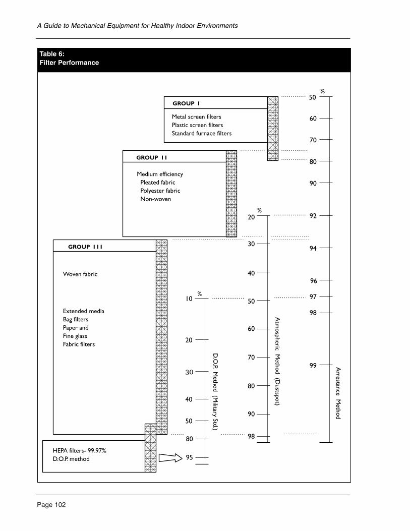
Page 102
A Guide to Mechanical Equipment for Healthy Indoor Environments
50
60
70
80
90
92
94
96
98
99
20
30
40
50
60
70
80
90
97
98
10
20
40
50
80
95
Metal screen filtersPlastic screen filtersStandard furnace filters
Woven fabric
Extended mediaBag filtersPaper and Fine glassFabric filters
HEPA filters- 99.97%D.O.P. method
GROUP I
GROUP I I
GROUP I I I
Medium efficiency Pleated fabric Polyester fabric Non-woven
Arrestance M
ethod
Atm
ospheric Method (D
ustspot)
D.O
.P. Method (M
ilitary Std.)
%
%
%
Table 6:Filter Performance
Filter maintenance
Filter maintenance is critical to proper operation.Regular checks, washing or replacement isessential. Sieve filters, such as extended mediafilters and high-performance filters, often becomemore efficient as they become loaded with dust.As they become fully loaded, however, they begin to restrict the airstream to the point where theyreduce the performance of the fan which movesair through them. In fact, a fully loaded furnacefilter can reduce air movement through the furnaceheat exchanger to the point where the furnace willno longer function. This will normally not happenunless replacement is severely neglected.Standard and medium-efficiency furnace filters,used in forced air heating may requirereplacement, two to four times annually. High-performance filters, such as bag filters, are oftenused after a standard filter and may only needannual replacement or less, due to their largesurface area.
Adsorption and reactive scrubbers also becomeless efficient as they become loaded. In fact, ifused in heavily contaminated circumstances, they will eventually cease to have any effect and, particularly adsorption media, will begin to release the compounds they have trapped back into the airstream. They may also becomecontaminated with bacteria or fungi if used underhumid conditions. For these reasons, regularreplacement of adsorption and reactive mediafilters is more critical than it is for sieve filters.
Filters used in portable room air cleaners mayinclude any or all four types discussed above.These will have widely variable servicingrequirements based on equipment type, room size,operating hours and quantity of air contaminants.It is best to observe the manufacturer’s recommendedreplacement schedule for this equipment.
Other Special Considerations for theEnvironmentally Hypersensitive
Filter materials and coatings
The environmentally hypersensitive may wish to
be very cautious about the type of material theychoose for a particulate filter. Some fabrics andfibres may have a slight odour or release smallamounts of dust or other gases.
The most common materials for low- andmedium-efficiency filters are polyester or spunglass mats or fabrics. These are generally madewith small amounts of resin binders to hold themtogether and they may be coated with oily orsticky materials to make them more effective.(See the discussion of filter coatings in thischapter.) The fibres themselves are generally notodorous, but glass fibres may release irritatingparticles when handled. For those few who may be affected by these materials, polyester-cottonblends or all-cotton fabric filters are alsoavailable in medium-efficiency types. Some high-efficiency filters are made from filter paper,or cellulose-glass paper blends, which usually are acceptable to the hypersensitive. They aregenerally very pure materials with no coatings.These are often used in very high-performance,portable air filters, such as HEPA units.
Because new particulate filters are usually made from synthetic fibres which tend to be very slippery, and they may hold a small staticcharge which repels some particles, they are oftencoated at the factory with a sticky material whichhelps to catch dust. This is called a “tackifier,” a viscous coating or sometimes an electret. Thematerials used are oils, waxy substances and sometypes of adhesives which do not harden. Thesecoatings do not present any problem to mostpeople, but may produce a slight odour which isirritating to the hypersensitive, particularly whenthe filter is new. Filter suppliers should be able to tell their customers if their filters are coated,and hypersensitive individuals can generally tell by smell if a filter is irritating to them.These coatings are most likely to be used on low-efficiency filters. They are unusual on medium- and higher-performance filters.
Ozone
Ozone is created by the reaction of oxygenmolecules in the presence of a strong electrical
Page 103
A Guide to Mechanical Equipment for Healthy Indoor Environments
Page 104
charge or ultraviolet light. Ozone has a relatively short life span and breaks down into oxygen quiterapidly. However, with a continuous source, it canbe a serious problem in housing, particularly to those with respiratory problems.
The most common sources of ozone are outdoorsfrom urban air pollution and electrical storms. Airpollution reacts in the presence of strong sunlightto form ozone and other hazardous gases. Ozonecauses burning eyes and nose, shortness of breathand swelling of the soft tissues in the throat andbronchia. Asthmatics, and those with emphysemaand other respiratory problems, can be acutelysensitive to ozone. However, it can also beproduced indoors from an electronic (plate andwire) air cleaner, open electric motor, laser printeror other high-intensity voltage field. Ozone isdetectableby its very pungent odour, even at very lowconcentrations of a few parts per billion (ppb), but it also has the property of paralyzing the sense of smell very quickly, so there is only a very limited time available to detect it.
Due to the risk of ozone, many hypersensitivepeople avoid electronic (plate and wire) aircleaners. Open frame motors, such as those inmany kitchen appliances and power tools, alsoproduce ozone and should only be used withadequate ventilation by the hypersensitive.
Ozone is also sometimes used intentionally as a means of air cleaning and odour removal. For example, some air cleaners produce smallamounts of ozone which are intended to reactwith odours and neutralize them. Though it iswell known that ozone has the ability to causechemical changes in many air pollutants whichwill render them less potent, it is difficult toestablish that ozone is an effective air treatment inoccupied spaces. Though small amounts of ozonewill reduce the apparent level of odours, this ispartly due to the paralyzing effect ozone has onthe nose. It is unlikely that ozone levels can bemaintained at a high enough level in an occupiedbuilding to be effective for odour removal withoutcausing health complaints.
In heavily contaminated buildings, such as those with smoke and water damage or funguscontamination, high-capacity ozone generatorscan be used temporarily for effective removal of lingering odours after clean-up. This methodreduces odour levels, but its effectiveness inkilling microbes is not known. It cannot be usedwhile people or pets are present, because it mustbe used at very high concentrations which wouldinjure them. It may also damage house plants,delicate fabrics, plastics, elastics and otherreactive materials.
Ion balance
Air contains gas molecules and particles that carry electrical charges. An electrically chargedgas molecule is called an ion and its state can be described as negative, (carrying an excess of electrons) or positive (lacking electrons). Inextreme conditions, such as during an electricalstorm or near high-voltage electrical equipment,the altered state of air ionization is quite apparentand recognizable by the pungent odour of ozone.
However, more subtle states of air ionizationprobably also affect our perception of air qualityand sense of well-being. Because air tends to lose its negative charges when it is containedwithin buildings or moved through metal ducts, it is well known that outdoor air contains morenegative ions than indoor air. One theory suggeststhat the perception of altered ionization is onefactor in complaints about stale air or stuffiness in buildings. Though this explanation iscontroversial among air quality researchers, somemanufacturers sell negative ion devices, as stand-alone units or as part of air cleaning equipment,and some people find that these improveperceived air quality.
Though ionization devices may be helpful tosome people, it should be emphasized that theyare not recommended for general use withoutcareful assessment of risks, costs and other indoor air quality strategies.
A Guide to Mechanical Equipment for Healthy Indoor Environments
Humidity control
Control of indoor humidity has been discussed inChapter 4, with emphasis on preventing extremeconditions which can lead to health risks. Theserisks normally occur at very low humidity levelswhich can cause respiratory irritation and highdust levels, or at very high humidity levels whichsupport microbial growth, dust mites and thepersistence of airborne bacteria and viruses.
The residential indoor air quality guidelinesadopted by the Federal-Provincial Working Group on Indoor Air Quality recommend anoptimum range of indoor humidity of from 30 to 55 per cent relative humidity in winter and 30 to 80 per cent in summer. This range is practical and achievable for most Canadians by adequate ventilation, occasional winterhumidification and summer dehumidificationduring extreme weather.
Very low relative humidity can irritate sensitiverespiratory tissue. It is best, where possible, tomaintain humidity at about 45 per cent. Higherrelative humidities support mildew growth and prolong the viable life of airborne bacteria,viruses and fungal spores. Good quality thermalwindows, at least double-glazed, will be necessaryto control condensation.
Dust mite control
Dust mites are highly allergenic, microscopicinsects which thrive in humid bedding, carpetsand fabrics. They are one of the most prominentcauses of dust allergy. Because dust mites thrivein damp conditions, moisture control is one of the most effective methods of dust mite control.Air filtration is also important. Regular washingof all bed linens in hot (not warm) water andcovering pillows, mattresses and box-springs in mite-proof or washable coverings is alsorecommended where dust allergy is a knownproblem. Mattresses and box springs should be vacuumed regularly.
Central vacuums
A built-in vacuum can be an important part of an indoor air quality strategy. Conventionalportable vacuums release a great deal of dustwhile in use, partly due to the inability of thefilter bag to contain fine particles, and partly due to the disturbance of the dust in the room.Furthermore, the motors in vacuums commonlyproduce ozone and oily odours when operated.Built-in vacuums can be very effective becausethe motor is usually powerful and the dust storageis remote from the user. Motorized cleaning headsare also available for some models which aredriven by air pressure and do not containelectrical parts which can produce ozone or insulation odours.
When planning for a built-in vacuum, the two primary concerns for the hypersensitive are locating the motor and dust storage unitoutside of the occupied areas of the home, andconnecting the motor exhaust duct to an outlet tothe outdoors. Some people may also react to thePVC duct and solvent glue used for connectingthe vacuum hose outlets, though this lasts only a short time. If this is a problem, it is possible toconstruct this part of the system with metal ductswith joints sealed with foil tape. Another optionsometimes used by the hypersensitive, is to wrapexposed plastic ducts carefully with metal foil and seal with foil tape.
In existing houses where a built-in vacuum isdifficult to install, or where cost is prohibitive,there are very high-performance portable vacuums available which have some of theadvantages of built-in systems. These may use very high-performance filters (HEPAstandard) to minimize the fine dust released by their use. Some models are designed to theexacting standards required for asbestos removaloperations. With careful handling, these can be animportant aid to dust removal when a built-invacuum is not feasible.
Page 105
A Guide to Mechanical Equipment for Healthy Indoor Environments
Page 106
Noise
Many hypersensitive people will have periods ofacute noise sensitivity as part of their condition.This may affect sleep and even daily activity. It is extremely important to reduce noise frommechanical equipment for this reason. Thecommon strategies employed are:
• selecting high-quality, low-noise equipment; • locating equipment as far as possible
from bedrooms and other commonly occupied rooms;
• isolating equipment by using vibration-absorbing mounts and duct connectors etc.;
• sizing equipment so it need not run at fullcapacity; and
• controlling equipment so it runs only whenneeded, and only at the speed that is needed.
Cleaning supply air where ambient conditionsare poor
In some locations, the outdoor air is socontaminated, that a filtration system should beinstalled to clean the supply air. Often, the systemwill include filters in the ventilation air supply of the HRV which exceed the capacity of thestandard filters supplied with the HRV. This is usually done with an auxiliary filter housingattached to the supply duct as it leaves the HRVbefore it leads to the supply air distributionnetwork. The filter housing may include pleatedfabric filters, electrostatic filters, charcoal filtersand, possibly, specialized chemical scrubbers. The filter housing should always accommodatefilters which are as large as is practical for thespace, and the manufacturer of the HRV should be consulted regarding the restriction produced by the filters. Please note that if the outdoor air is heavily polluted only part of the time, a practical approach is to turn off the HRVduring these times.
Chlorine removal from tap water
Most public water supplies are chlorinated to prevent the spread of infectious organismsthrough water supplies. Chlorination, however,
produces gases such as chloroform, which arevolatile and become airborne. Though the obvious route of exposure is through drinking and cooking, it is also important to note that about half of a typical person’s exposure tochlorine compounds is through inhalation ofvapours and skin absorption while showering.Gases and other contaminants can be removed bya whole-house filtration unit containing activatedcarbon. Where the cost of installing such a unit is prohibitive, a high-capacity shower filter andkitchen filtration unit may be an acceptablealternative. See Chapter 7 for more details.
Air Ionizers/Ozone Generators
• Electrically charged elements generatenegative ions.
• An ultraviolet chamber or electrical dischargegenerates ozone.
Typical system applications
As a tabletop unit or part of a multi-stage air cleaner.
Installation considerations and options
Typically only portable units.
Health issues
Advantages
• Negative ions may enhance apparentfreshness of air and can reduce suspendeddust. Ozone will reduce odours of somegases. Effectiveness of both is controversial.
Disadvantages
• Ozone in the indoor air is not recommended.
General comments
• Ionizers are sold for dust control.Effectiveness is uncertain.
A Guide to Mechanical Equipment for Healthy Indoor Environments
• High potency ozone generators are often used for effective odour removal (i.e., afterfire damage) but must be used in unoccupiedbuildings as high ozone levels are hazardous.Ozone can cause materials to deteriorate.Some very sensitive individuals are adverselyaffected by very low levels of ozone.
• Use of ozone generators for cleaning the air isnot recommended.
• Greater reliance should be placed onremoving the contaminants at the source.
Maintenance requirements
Occasional cleaning.
Operating cost/savings
Small electrical cost.
Product sources
• Specialty filtration suppliers; and• allergy product suppliers.
Adsorption Air Filters
Charcoal granules in fabric pockets, metal trays or charcoal treated fabric. Zeolite in fabric pockets. Charcoal and zeolite trap gases by adsorption.
Other common names
• Charcoal or activated charcoal;• activated carbon; • zeolite filters;• odour removal filters; and• adsorption media forced air heating systems
and HRVs.
Typical system applications
As second stage filters in air cleaners or metaltrays, for odour removal or occasionally infurnaces, fan coils and HRVs.
Installation considerations and options
• Most effective in recirculating air systems.
• Low airflow rate preferred.
• Charcoal source may be hardwoods, coconutshell or peat.
• Treated fabrics available for both particle andgas removal.
• Cannot be used in humid conditions.
• Should have effective particulate filterupstream and downstream.
Health issues
Advantages
• Charcoal will trap many gases but is lesseffective for formaldehyde and otherlightweight gases.
• Zeolites will trap ammonia and otheralkalines (especially urine odours).
• Very useful for reducing household odoursand odours from outdoors such as woodsmoke.
Disadvantages
• Must be replaced before saturated, otherwisethe contaminants can be re-emitted.
• Charcoal and zeolite replacement is based onodour or a schedule.
• Adsorption media are costly.
• Refilling trays or containers is tedious andgenerates dust.
General comments
• Source of charcoal may be important for the hypersensitive. Coconut shell is often tolerable.
Page 107
A Guide to Mechanical Equipment for Healthy Indoor Environments
Page 108
• Must be changed regularly and kept dry. Not for use in humid environments.
• Also used in emergency filter masks for the hypersensitive.
Maintenance requirements
Regular filter changes.
Operating cost/savings
Cost of replacement of disposable media.
Product sources
• Specialty filter suppliers; and• allergy product suppliers.
See also the information on portable air cleanersin this chapter.
Built-in Vacuum
A large vacuum motor and filter bag are ducted to several wall outlets. The vacuum head ormotorized carpet brush is plugged into one of these outlets.
Other common names
Central vacuum.
Typical system applications
As a new or retrofit vacuum system.
Installation considerations and options
• Separate electrical circuit for central unit.
• Sixty millimetre (2 1/2 in.) diameter PVCduct to outlets.
• Vacuum exhaust can be ducted to outdoors.
• Air-powered carpet brush motor available.
Health issues
Advantages
• Minimizes fine dust stirred up by portable vacuums.
• Allergens which pass filter can be ducted outdoors.
• Vacuum motor can be located in isolation to reduce noise and motor odours.
• Air-powered carpet brush produces no motor odours.
Disadvantages
• PVC duct and glue may not be tolerated bythe hypersensitive. These can be sealed.
General comments
A high-performance, portable vacuum using a HEPA final filter may be an acceptablealternative. These should meet asbestos removal standards.
Maintenance requirements
Periodic canister cleaning. (Note: allergicindividuals should wear a filter mask when cleaning.)
Product sources
• Building contractors; and• vacuum suppliers.
Electronic (Plate and Wire) Air Cleaners
Electrically charged plates trap fine dust by staticattraction.
Other common names
Electrostatic precipitator.
A Guide to Mechanical Equipment for Healthy Indoor Environments
Typical system applications
• Furnace filter upgrades.
• Portable room air cleaners.
Installation considerations and options
Requires continuous electrical supply and adequatespace for installation. Airflowing into the filtershould be smooth and unobstructed.
Health issues
Advantages
• Very effective for fine dust and smokeparticle removal.
Disadvantages
• Produces small amounts of irritating ozone. Caution is suggested particularly with asthmatics and the environmentallyhypersensitive.
• Installation in retrofits where there isinadequate length of duct to the filter unit, or where the unit is located next to a bend in the ducting, may contribute to higher ozone production.
General comments
• Must have appropriate airflow rate for proper function.
• Often noisy (popping or crackling sounds).
Maintenance requirements
• Regular cleaning.
• Monitoring to ensure electrical chargeis not lost.
Operating cost/savings
Small electrical cost for operation.
Product sources
• Heating and ventilation contractors; and• Specialty filtration suppliers.
Extended Media Filters
• Pleated units are medium efficiency withmoderate flow resistance, made from glass,polyester or cotton blend panels.
• Bags have moderately high efficiency andflow resistance, made from polyester orcotton blend.
• HEPA units are high efficiency with high flowresistance, made from compressed fibre fabricor paper.
Other common names
• Fabric filters; and• Dust filters.
Typical system applications
In furnaces, fan coils, HRVs and room aircleaners usually for removing coarse to medium particles.
Installation considerations and options
• Pleated units can typically be retrofitted tofurnaces or fan coils without modifications.
• Medium efficiency available with charcoaltreatment for odour removal.
• Bag filters require extra filter housing andpossibly stronger fans.
• HEPA can only be used with speciallydesigned blower units.
Page 109
A Guide to Mechanical Equipment for Healthy Indoor Environments
Page 110
Health issues
Advantages
• Pleated units effectively remove pollen, finedust, animal dander, etc.
• Bags remove fungi and smoke particles.
• HEPA units remove bacteria and very fine particles.
Disadvantages
• Airflow decreases as they become loaded.
General comments
• Fan capacity must be adequate to overcome resistance.
• Avoid fungicide-treated filters.
Maintenance requirements
Regular changes when loaded.
Operating cost/savings
Cost of replacement units for disposable types.
Product sources
• Heating and ventilation contractors;• specialty air filtration suppliers; and• allergy product suppliers.
Furnace Filter Upgrades
Medium-performance particle filters (pleatedfabric), electrostatic filters or charcoal odourremoval filters. Minimum of 400 mm x 600 mm x 50 mm (16 in. x 24 in. x 2 in.).
Other common names
• Pleated filters;• Electrostatic filters; and• Charcoal filters.
Typical system applications
Additional filters for forced air systems.
Installation considerations and options
• Must be large enough to minimize restrictionof airflow. Additional sheet metal work andpossibly a larger fan may be necessary.
• Manufactured filter boxes are available to fit furnaces.
Health issues
Advantages
• Can remove some pollens, animal dander, finedust and odours.
• A popular upgrade for forced air systems.Best if combined with a low-temperature heat exchanger.
General comments
• Filters in a recirculated airstream are moreeffective than in a one-time application (i.e., filtered HRV supply).
• High-performance filters are generally toorestrictive for furnaces. A separate blowersystem is required.
Maintenance requirements
Regular filter replacement of cleaning(electrostatic units).
Operating cost/savings
• Increased fan energy cost.
• Electronic units use a small amount of electricity.
• Replacement cost of disposable filters.
A Guide to Mechanical Equipment for Healthy Indoor Environments
Product sources
• Heating and sheet metal contractors; and• Specialty filter suppliers.
See also the information on the specific airfiltration types in this chapter.
Passive Electrostatic Air Filters
Permanently charged plastic mesh traps fine dust.Usually polypropylene filter mesh.
Other common names
• Permanent electrostatic filter; and• electret filters.
Typical system applications
• Furnace retrofits.
• Occasionally in portable units and HRVs.
Installation considerations and options
• Typically will fit in standard furnace filter space.
• Continuous fan operation recommended.
• Twenty-five millimetre, 50 mm (1 in., 2 in.)thick and custom sizes available.
Health issues
Advantages
• Effective removal of medium-sized dust andsome smoke particles.
• Often used instead of electronic units due toozone concerns.
Disadvantages
• Not as effective as electronic filters.
• Core layers of multi-layer washable filters arenot easily cleaned.
General comments
• No noise, no operating costs and simple installation.
• Some fine dust still passes through.
Maintenance requirements
• Regular cleaning of mesh screens byvacuuming and washing filters that are washable.
• “Permanent” filters still need to be replacedafter some time. Inspect the layers at thecentre for staining.
Operating cost/savings
None.
Product sources
• Specialty filter suppliers; and• allergy product suppliers.
Portable Air Cleaners
A box with a fan and two or more filters.
Other common names
Room air cleaners.
Typical system applications
For dust and odour removal in small, enclosedrooms or apartments.
Installation considerations and options
• Many filter configurations are available.
• Automobile units available.
• High-efficiency (HEPA) units available.
• Available in all metal construction, no plasticsor rubber parts.
Page 111
A Guide to Mechanical Equipment for Healthy Indoor Environments
Page 112
• Check that there are no parts made of particleboard or medium-density fibreboard (MDF).
Health issues
Advantages
• Can offer moderate benefits for dust and odour removal in small rooms. Not asubstitute for source control and ventilation.
• Often used to improve air quality inapartments and houses when major changesare impractical.
Disadvantages
• Limited ability to clean air in a large room.
• Noisy and generate heat.
• Motors and components may generate odours.
General comments
• The largest practical capacity unit should be used.
• Some units are noisy.
Maintenance requirements
Occasional filter changes and cleaning.
Product sources
• Specialty air cleaning suppliers; and• allergy product suppliers.
See also the information on specific filter types in this chapter.
Reactive Gas Scrubbers
Typically activated alumina impregnated withpotassium permanganate, sodium hydroxide and other agents. Gases are trapped then brokendown (oxidized by the permanganate; acids areneutralized by sodium hydroxide).
Other common names
• Absorption filters;• activated alumina filters; and• permanganate filters.
Typical system applications
As second or third stage filters in air cleaners for odour removal.
Installation considerations and options
• Used for cleaning recirculated air.
• Effective for scrubbing incoming fresh air.
• Low airflow rate preferred.
• Should be protected by particulate filtersupstream and downstream.
Health issues
Advantages
• Permanganate units will break downformaldehyde, hydrogen sulphide, natural gas odours, chlorine and other gases.
• Activated alumina with potassiumpermanganate have built-in indicators. Pinkpellets turn brown to the core when spent.
• Alkaline units will neutralize acids, chlorine,bromine and fluorine.
Disadvantages
• Media are costly.
• Refilling is dusty and tedious.
General comments
• A common element in multistage air cleanersfor the hypersensitive.
• More effective than charcoal forformaldehyde and natural gas odours.
A Guide to Mechanical Equipment for Healthy Indoor Environments
Maintenance requirements
Regular filter changes. Effectiveness lost with age and use.
Operating cost/savings
Cost of replacement of disposable media.
Product sources
• Specialty filter suppliers; and• allergy suppliers.
See also the information on portable air cleanersand vacuum equipment in this chapter.
Turbulent Flow Precipitators
• Particles are separated from the airstream byturbulent airflow created by a fan.
• No filter media are needed.
Other common names
TFP.
Typical system applications
Installed in supply side of an HRV or in the returnair plenum of forced air systems.
Health issues
Advantages
• Does not produce ozone.
• Effectively removes particles to 0.1 micron.
• Low maintenance requirements.
• Performance does not depend on the loading.
General comments
• Only a portion of the air (up to 135 cfm)passes through the TFP at a time. When large amounts of pollutants are introduced or generated in the house, it may take time to bring the levels down.
• Sensitive individuals should test the unit.
Maintenance requirements
Clean collectors annually or more frequentlydepending on the amount of dust.
Operating cost/savings
Some electrical cost.
Product sources
One manufacturer in Canada through heating andventilation contractors.
See also the information on table air cleaners andvacuum equipment in this chapter.
Page 113
A Guide to Mechanical Equipment for Healthy Indoor Environments
Page 114
Concerns about the quality of rural and municipalwater supplies are increasing. The quality of rawwater supplied to municipal plants from surfacesources has been declining for many years,particularly in the densely populated areas. This is mainly due to industrial and sewage discharges,land development and agricultural run-off. Manywho rely on groundwater are now also faced withcontamination from industrial waste and landfills.Home water treatment systems or bottled drinkingwater are now widely used.
However, not all water quality problems arecreated by human activity. Excessive hardness(mineral content), metal and salt content, andhydrogen sulphide are some of the common,naturally occurring problems. Only a few arelucky enough to live in locations where theyreceive very pure water from wells and springswhich requires no treatment at all.
One of the first principles of successful watertreatment is to determine what may be necessary.Water contaminants must be identified, and thetreatment specifically designed for the conditions.Fortunately, unlike air quality problems which can be very difficult to identify by testing, water quality testing is a relatively simple andinexpensive procedure. A basic water test forcoliform bacteria, minerals, metals and salt isroutine and costs about $25 to $50. If you are on a municipal system, these tests are doneperiodically by the local water authority, and theresults can be obtained from them. Tests for heavymetals, agricultural chemicals or industrial wasteare more expensive and are done by speciallaboratories.
Water Purification Systems and Equipment
There are two basic types of water purificationsystems: point-of-use systems and whole-housesystems. The point-of-use system treats only thewater at one location. It may treat the water as it
passes through the tap or shower, or deliver it to a small storage container and then to a special tap,usually installed in the kitchen. This tap is thenused for drinking and cooking. The whole-housesystem treats potable water before it enters thehome plumbing, and may treat all the water, orjust the water that flows to the kitchen andbathrooms. There is usually no treatment done for water used for yard and garden, and oftenuntreated water is used for toilets and washing.
Most water treatment systems can be retrofitted to existing plumbing almost as readily as they canbe installed in new plumbing. The only exceptionis a whole-house treatment system which isintended to serve some plumbing fixtures and not others. This type of installation may requirealteration to some of the supply pipes to separatethese fixtures. Some systems also require anelectrical supply and a drain for dischargingwastewater which is diverted past the filters or used for filter backwashing. This should be considered when planning an installation.
Types of water treatment
Each type of water treatment is designed forremoval of specific contaminants.
Sediment removal
Sieve filters are most commonly used for thispurpose. These are usually disposable cartridgesmade from polyester or mineral fibre fabrictightly woven around a plastic core. When water is forced through these, small particles are trapped in the fabric.
Sediment filters are effective for particles of about five microns and larger, and do notgenerally produce excessive restriction to waterflow. They can be used in whole-house filters.They are effective for most sand, soil and clayparticles, rust residue and other visible sediment.These should always be used where sediment is a common problem and to protect more delicate
7. WATER TREATMENT
filtration equipment, such as reverse osmosisunits, from sediment blockage. Sediments areusually not a health risk unless they containmetals, industrial waste or soils from surface run-off which may carry bacteria.
Mineral removal
Hard water is a common problem in many parts of Canada, particularly where groundwateris drawn from limestone formations. Hardness is usually defined as an excess of calciumcarbonate, though other minerals may beinvolved. Hardness is generally only a nuisancebecause it causes staining of fixtures, poorperformance of soaps and plugging of pipes.Water softening is typically done by packagedsoftener systems using a tank containing an ion-exchange resin which attracts and traps theminerals. The tank is then periodically flushedwith salt which removes the trapped minerals and restores the resin. Though high mineralcontent is not usually considered a health risk, the unavoidable salt residue introduced by thesoftener after replenishing may be a risk to thoseon low sodium diets.
Sterilization
Surface water or groundwater subject tocontamination by sewage or animal waste has ahigh risk of carrying coliform bacteria and otherdisease-causing organisms, such as amoebae andgiardia, in many areas in Canada. This risk iswidely considered to be the major public healthproblem with water systems. Though municipalwater is sterilized with chlorine, some ruralsystems and independent wells and springs mayrequire in-home sterilization. The usual methodsare ultraviolet light and ozone treatment, thoughchlorine is also sometimes used. Ultraviolet andozone treatment use high-energy electron sourcescontained in a contact chamber to destroyorganisms. An advantage of this system is that, unlike chlorination, the process leaves nohazardous and polluting residue in the water.
Metal removal
Water supplies occasionally contain quantities of metals, such as iron, which are a nuisance;more toxic metals are sometimes present.Treatment systems similar to water softeners maybe used for removal of some metal, or specializedchemical methods may be used. Metal removalmay be also accomplished by processes such asreverse osmosis. (See organic compound removaland salt removal below.) Generally, where seriousmetal problems are present, a treatment system is required, designed specifically for localconditions. In these circumstances, a watertreatment consultant, familiar with localconditions, should be used.
De-chlorinating
Chlorination of water supplies results in residual chlorine and other by-products whichmany health authorities now believe are apotential health risk. The most common methodof removal is an activated charcoal or carbonblock system which must be periodicallydiscarded. This is an effective method, whetherused as a whole-house system or at point of use. The most important feature of an effectivecharcoal system is the quantity of charcoalcontained in it, and how often it is replaced orrecharged. Only systems with large volumes ofcharcoal are effective. However, once chlorine hasbeen removed, water is again prone to microbialcontamination. It should not be stored for lengthyperiods, or a sterilization unit should be added.(See sterilization above.) Some carbon filters are impregnated with silver as a bactericide. The effectiveness or impact of silver on the water is not known.
Salt removal
Reverse osmosis systems are the most popular for salt removal. These units force water underpressure through a selective membrane. Mostcontaminants will not pass through the membrane.
Page 115
A Guide to Mechanical Equipment for Healthy Indoor Environments
Page 116
The process is slow and often energy intensive,and a large storage tank is required for fresh water supply to the house. The process requires a continuous flow past the membrane to prevent it from clogging. The bypass flow water isdischarged to a drain. Typically, at least five litresof water are flushed for each litre of purifiedwater. The membrane should be examinedvisually on a regular basis (or conductivity teststaken) to determine how often the membraneshave to be replaced. It may be possible to use the bypass water for non-potable purposes, e.g., toilet flushing.
Distillation
This process removes minerals, heavy metals,other inorganic contaminants and organicmaterials of low volatility. Bacteria and molds are unlikely to survive the boiling process.Distillation effectively removes inorganicsubstances. Volatile organic substances, however,can be carried over with the water vapour. Carbonfiltration combined with distillation wouldremove both types of contaminants.
Organic compound removal
Reverse osmosis units may also be used fororganic compound removal. Point-of-use filtersusing ceramic elements or distillers can alsoremove salt and some organic compoundseffectively in selected faucets. Charcoal filteringmay also be used for organic compound removal,but should be preceded by a reverse osmosis or ceramic filter if contamination is serious.Charcoal alone is not entirely effective and will become contaminated too quickly.
Buffering
In some situations, water is acidic due to itssource, usually in watersheds with pine and firforests and acidic soil. Acidic water will leachmetals such as lead and copper from plumbing,and will cause staining of metal fixtures andreduced life for pipes. A whole-house bufferingunit is usually a tank containing an alkalinematerial, such as ground limestone or sterilized
oyster shell, which will reduce the acidity ofwater. The alkaline buffer must be renewedperiodically as it is consumed. Where acid wateris a problem, these systems are effective forreducing copper and lead content and prolongingthe life of fixtures and pipes. Often, the unitcontains charcoal for removal of chlorineproducts. Very alkaline water usually has anexcess of calcium carbonate and can be treatedwith water softeners.
Equipment Cost
The least costly water treatment units are point-of-use charcoal filters such as countertop units,under-counter units or shower filters for chlorineremoval. These are available for $50 to $200. The most important considerations are the amountof charcoal contained in the unit and the cost ofcharcoal replacement.The consumer should becautious and note that very inexpensive, smalldisposable units are probably not very effective,and will cost more when their short lifespan is considered. At the same time, there are many overpriced charcoal units sold throughquestionable marketing schemes which requirevery costly charcoal replacement. The bestcharcoal units are reasonably priced andinexpensive to renew. Some are available fromdepartment stores and mail order services.
A more sophisticated point-of-use unit designedfor the countertop often contains a reverseosmosis or ceramic filter, followed by a charcoalfilter. These cost about $300 to $400. Countertopdistillation units are available in a higher pricerange. An under-counter unit containing reverseosmosis and charcoal with a small storage tankcosts about $400 to $500, including installation of a special tap on the sink top.
Whole-house filters vary widely in costdepending on the treatment requirements andcapacity. A whole house charcoal unit for chlorineremoval can be built on basic water softenerhardware (without the softener resin) and will cost about $1,400 installed. It may also contain abuffer if acidic water is a problem. Other whole-house systems for softening and metal removal
A Guide to Mechanical Equipment for Healthy Indoor Environments
are in the same price range. A whole-house saltremoval system or other specialized system, usinga large reverse osmosis membrane and storagetanks, may cost several thousand dollars includingpumps, tanks and wiring.
Equipment Maintenance
All water treatment equipment requires periodicmaintenance and replacement of disposablefilters. This is particularly important with units using charcoal filters, because these will become contaminated over time and maysupport hazardous bacteria. Replacement ofsmaller sediment filters and charcoal units is necessary periodically and may cost from $5 to $40. Larger units may only require annualreplacement. Reverse osmosis and ceramicelements will need occasional replacement,depending on what quantities of contaminantsreach them. Reverse osmosis membranes and ceramic filters usually cost about $50 to $150 to replace.
It is always best to trust service of anysophisticated water treatment equipment to aqualified and reputable service contractor. Servicecan often be purchased for a reasonable annualfee. However, it is wise to do some carefulconsumer research before entering into anagreement with a water treatment company.
Water Conservation
Water conservation measures, such as low-flow fixtures, low-flush toilets and a thoughtfulconservation lifestyle, are always appropriate.This is even more true if water in the home hasbeen treated by costly systems. Moderation ofwater use may permit a downsizing of watertreatment equipment which will reduce initial cost of the system and ongoing costs ofpurchasing or pumping and heating water.
Charcoal/Carbon Filter
Granular charcoal or compressed charcoal blocksprovide millions of pores for trapping impurities.
Other common names
• Odour filter;• chlorine removal filter; and• adsorption filter.
Typical system applications
As a final stage in treatment systems beforedelivery of filtered water. It can be a small unit(point-of-use) or a whole-house unit for treatingall the water supply.
Installation considerations and options
• Requires slow flow-through rate foreffectiveness.
• Charcoal source may be hardwoods, coconut shell or peat.
• Large vessels filled with granular charcoalshould be backwashed periodically to preventchanneling which allows impurities to escape.
• Should be followed by a sterilization unit toprevent bacterial contamination.
Health issues
Advantages
• Can effectively remove chlorine and othercompounds caused by municipal chlorination.
• Can remove some sulphur and other odours.
• The type of charcoal may determine the acceptability of the filters tohypersensitive individuals.
Disadvantages
• Not a safe method of treating water with high concentrations of hazardous contents(solvents, agricultural chemicals, etc.).
• Poor maintenance or absence of a sterilizercan lead to microbial contamination.
Page 117
A Guide to Mechanical Equipment for Healthy Indoor Environments
Page 118
• The contaminants can break through or be re-released when the charcoal is exhausted.
General comments
• Used charcoal may release contaminants.
• Filters must be changed regularly.
• Some units contain small amounts of silver to retard bacteria growth.
Maintenance requirements
Charcoal replacement as required. The need forreplacement is usually gauged by taste.
Operating cost/savings
Cost of replacement media.
Product sources
Water filtration suppliers.
See also the information on whole-house filters, point-of-use filters and sterilization units in this chapter.
Distillation Equipment
Tap water is heated by an electric element andcondensed steam is collected for use.
Other common names
Water stills, distillers.
Typical system applications
• As a countertop unit with a storage vessel for treating cooking and drinking water.
• Occasionally as a built-in unit.
Installation considerations and options
• Countertop units approximately 250 mm x400 mm x 250 mm (10 in. x 16 in. x 10 in.) in size.
• May require separate electrical circuit.
• Can be tapped into supply line for in-linecontinuous operation.
• Produce heat while operating.
Health issues
Advantages
• Very effective removal of most impuritiesincluding metals, minerals, bacteria and someorganic compounds.
• Does not require pre-chlorination of water.
• One of the most desirable for well water purification.
• Compared to reverse osmosis, does notrequire a minimum water pressure.
Disadvantages
• Some volatile impurities such as chlorinationby-products or volatile organic chemicalcontaminants are released to the air and can re-enter finished water. Ventilation should be provided over the distiller toremove chlorine or other gases, if the water supply is chlorinated.
General comments
• Can be used as a countertop unit for kitchenwater, but may generate too much heat.
• The heat generated by the distiller can beused for drying clothes in a ventilated room.
• Water tastes flat.
Maintenance requirements
Regular flushing of boiling chamber and de-scaling as required.
A Guide to Mechanical Equipment for Healthy Indoor Environments
Operating cost/savings
High electrical usage.
Product sources
• Water filtration suppliers; and• allergy product suppliers.
See also the information on point-of-use filters inthis chapter.
Membrane Filters
• Reverse osmosis: water is forced through asemi-permeable membrane which preventsmany impurities from passing through. Only a fraction of the water flowing through themembrane is purified.
• Ceramic: water is forced through a thinceramic cylinder.
• Flow rate is slow (10 to 50 ml/min.) for small units.
Other common names
• Reverse osmosis; and• ceramic filters.
Typical system applications
• As a second-stage filter in point-of-usesystems, after sediment filtration.
• Often followed by a charcoal filter.
Installation considerations and options
• Used in under-counter or countertop units.
• Both stainless steel and PVC plastic housingsare available.
• Water-saver control is available.
• Pre-treatment of the water with chlorinereduces microbial growth on the filter.
Health issues
Advantages
• Can remove salts, bacteria, fine sediment and, if it has a charcoal filter, some organic compounds including chlorination by-products.
Disadvantages
• Small molecules are not retained by membranes.
• Cannot remove all dissolved metals.
• Possibility of microbial contamination of the membrane.
• There is no easy way to tell when themembrane should be replaced.
• Reverse osmosis units operate with minimumwater pressure requirements and may not bethe best choice if the water pressure is low or fluctuates.
• Large volume of bypass water is wasted.
General comments
Both are prone to clogging and should beprotected by a sediment filter. Ceramic filters are very fragile. Note that large-scale, commercialreverse osmosis units are professionally servicedand maintained on a regular basis. Units installedin homes must be maintained by the owner.
Maintenance requirements
• Occasional replacement. Pull out and visuallyexamine the membrane for loading.
• Charcoal filter must be replaced regularly.
• Regular pre-filter replacement to protect membrane.
Page 119
A Guide to Mechanical Equipment for Healthy Indoor Environments
Page 120
Operating cost/savings
Replacement cost for membranes.
Product sources
• Water filtration suppliers; and• allergy product suppliers.
See also information on point-of-use filters,sediment filters and charcoal filters in this chapter.
Metal or Mineral Removal Filters
A vessel containing an ion-exchange resin attracts minerals or metals. Collected minerals are occasionally flushed to a drain by anautomatic backwash cycle using salt to renew theresin. Treated water is typically for domestic uses.
Other common names
• Water softeners; and• iron (or other metal) filters.
Typical system applications
As whole-house filters for water with highmineral or metal content.
Installation considerations and options
• Standard softeners are used for high mineral(calcium carbonate) content. Special units areavailable for specific metals (i.e., iron).
• A drain and electrical supply are required. A bypass line can be installed for a separatekitchen faucet.
Health issues
Advantages
• High mineral content is a nuisance, not amajor heath concern.
• Conditions water and reduces scaling or staining.
Disadvantages
• Softness may add salt to finished water.Caution for those on low sodium diets.
• Replenishing salt is a chore.
General comments
Water bypasses without treatment duringbackwash cycle.
Maintenance requirements
Occasional checks and periodic addition of salt.
Operating cost/savings
Cost of salt.
Product sources
• Water treatment suppliers; and• water softener companies.
Point-of-Use Filters
• Usually has two or more stages.
• Sediment filter removes particles toapproximately five microns.
• Reverse osmosis or ceramic filter removesorganic compounds, salts, bacteria and some metals.
• Charcoal filter removes chlorine and odours.
• A small storage vessel, often pressurized, is required.
Other common names
• Countertop filters; and• under-counter filters. (See also
distillation equipment.)
Typical system applications
For cooking and drinking water treatment.
A Guide to Mechanical Equipment for Healthy Indoor Environments
Installation considerations and options
• Reverse osmosis or ceramic/charcoal unitsrequire drain connection.
• Under-counter units require approximately a 500 mm x 300 mm x 150 mm (20 in. x 12 in. x 6 in.) space.
• Units with pressurized storage require anextra tap at sink.
• Sediment/charcoal units can use bypass valveon kitchen tap.
Health issues
Advantages
• Various filter combinations can remove nearlyall impurities.
Disadvantages
• Storage vessels should be made of stainlesssteel or glass. Rubber bladders may not beacceptable to some individuals.
• Poor maintenance leads to contamination.
General comments
• Small charcoal filters which fasten on to tapsor showers are not effective. Filters shouldcontain sediment pre-filters and 750 g (l.5 lbs)of charcoal minimum.
• Reverse osmosis units discharge bypass water to drain. Water use can be reduced with automatic shutoff valve.
Maintenance requirements
• Periodic filter and charcoal replacement.
• Periodic reverse osmosis or ceramicmembrane replacement.
Operating cost/savings
Replacement cost of filter or membrane.
Product sources
• Specialty water filtration suppliers; and• allergy product suppliers.
See also the information on the various filtertypes in this chapter.
Sediment Filters
Disposable cartridges made from polyester fibrein metal or plastic (PVC) housings. Fibre meshtraps particles.
Other common names
• Sieve filters; and• particle filters.
Typical system applications
As a pre-filter or whole-house sediment filter to protect other filters.
Installation considerations and options
• Filters cause some flow restriction. The unitmust be large enough for expected flow.
• Filters particles two to 10 microns in size.
• Can be used for whole-house or point-of-usesystems.
Health issues
Advantages
• Removes most sand, soil and clay particleswhich cause turbidity (cloudiness), thoughmost particles are not health risks.
• Poor maintenance is indicated by poor flow.
Page 121
A Guide to Mechanical Equipment for Healthy Indoor Environments
Page 122
Disadvantages
• Cannot remove dissolved contaminants.
General comments
Should be used as a pre-filter in any watertreatment system to protect filter membranes and charcoal from clogging.
Maintenance requirements
Periodic filter replacement as required.
Operating cost/savings
Cost of replacing disposable filters.
Product sources
• Plumbing contractors; and• water filtration suppliers.
See also the information on whole-house andpoint-of-use filters in this chapter.
Sterilization Units
• A powerful ultraviolet lamp in a contactchamber with water flowing slowly past.
OR
• An electronic ozone generator pumps ozoneinto a contact chamber. Water must be ventedfor a few minutes for ozone to disappear.
Other common names
Ultraviolet or ozone treatment.
Typical system applications
• For whole-house treatment where microbialcontamination is a concern, i.e., rural water systems.
• Occasionally as a final stage in whole housetreatment of municipal water to preventcontamination after chlorine removal.
Installation considerations and options
• Requires separate electrical circuit and controls.
• May require storage tanks and pumps.
• Automatic self-cleaning available for UV lamps.
Health issues
Advantages
• Effectively destroys micro-organisms such ascoliform, bacteria, amoeba and giardia.
Disadvantages
• Ozone must be vented to outdoors, away fromwindows and ventilation intakes.
General comments
Usually only used where water is contaminated bysurface run-off. Can be used after charcoal filtersto protect from bacterial contamination.
Maintenance requirements
Ultraviolet contact units require regular lampcleaning to prevent scum buildup.
Operating cost/savings
Consumes moderate amounts of electricity.
Product sources
Specialty water filtration suppliers.
See also the information on whole-house andcharcoal filters in this chapter.
Whole-House Water Filtration
Usually has two or more stages:
• sediment filter removes particles toapproximately five microns;
A Guide to Mechanical Equipment for Healthy Indoor Environments
• charcoal filter removes chlorine and odours;• sterilizers (ultraviolet or ozone) to destroy
bacteria; and• buffers (alkaline materials) to neutralize
acidity (if required).
Other common names
Point-of-entry filter.
Typical system applications
Filtration of all water to kitchen, baths andlaundry. Garden taps are usually not filtered.
Installation considerations and options
• Requires connection at main water entrance.
• Requires floor space for tank.
• May require electrical outlet and drain.
• Some units may use reverse osmosis andstorage for salt or metal removal.
• System design depends on water contaminants.
Health issues
Advantages
• Can minimize chlorine exposure in shower.
• Can remove many contaminants from naturalcauses, agriculture and industry.
• Popular system for those on city water. May also be used with a kitchen filter fordrinking water.
Disadvantages
• Does not sterilize water.
• Poor maintenance leads to contamination.
General comments
Can be built around standard water softenerhardware using charcoal and buffer (if necessary)in place of softener resin. Timer can be used forbackwashing to preserve charcoal effectiveness.
Maintenance requirements
• Filter and charcoal replacement (based onmanufacturer’s recommendations).
• Buffer renewal.
Operating cost/savings
Cost of replacing disposable filters and media.
Product sources
Specialty water filtration suppliers.
See also the information on the various filtermedia types and on sterilization units in thischapter.
Page 123
A Guide to Mechanical Equipment for Healthy Indoor Environments
Page 124
Bower, John. (1995). Understanding Ventilation. Indiana: The Healthy House Institute.
CMHC (Canada Mortgage and Housing Corporation). (1998). Guide to Ventilation Systems: Consumer Series. Ottawa.
——––. (1998). The Clean Air Guide. How to Identify and Correct Indoor Air Quality Problems in Your Home,rev. ed. Ottawa.
——––. (1997). Building Materials for the Environmentally Hypersensitive, rev. ed. Ottawa.
——––. (1997). Towards Healthy House Renovations: Research on Trends and Practices Relating to HealthyHousing, Indoor Air Quality and Ventilation within the Residential Renovation Industry. Ottawa.
——––. (1996). Optimizing Residential Forced Air HVAC Systems. Ottawa.
——––. (1995). Combustion Gases in Your Home: Things You Should Know About Combustion Spillage. Ottawa.
——––. (1995). Ventilation System for New and Existing Houses with Baseboard Heating. Ottawa.
——––. (1993). Efficient and Effective Residential Air Handling Devices: Final Report. Ottawa.
——––. (nd). Maintaining Your HRV, About Your House series, No. 9. Ottawa.
SELECTED REFERENCES
APPENDIX A:
DEFINITIONS
Page A-1
Page A-2
AbsorptionChemical agents can be used for collecting orneutralizing gases by reacting with them. Thiseffect is used for air cleaning using materials such as potassium permanganate.
AdsorptionPorous and rough surfaces are capable ofcollecting gases because gas molecules aretrapped inside the microscopic matrix. This effect is used for air cleaning using materials such as activated charcoal.
Air BarriersAn air barrier is designed to restrict the movement of air into insulated cavities. It mayalso incorporate a vapour diffusion retarder. Thecontinuous air barrier consists of an assembly ofbuilding materials in the exterior floors, walls andceilings that are joined together to minimize airmovement through the building envelope. Itspurpose is to limit the movement of moisture into insulated cavities and entry of pollutants into the house from outside and from materials in the insulation cavities. The Airtight DrywallApproach is a complete system of air-barrier and vapour-diffusion retarder construction fornew housing that uses drywall as the primarybarrier component.
Backdrafting (Back Venting or Flue Gas Spillage)A conventional chimney serving a furnace, heateror fireplace depends on the buoyancy forces ofwarm combustion gases to carry them outside.This is a weak force and can easily be overcomeby a strong exhaust fan in a house or by windconditions, particularly when the chimney is cold. When this occurs, these hazardous gasesenter the home, a situation called backdrafting,back venting or flue gas spillage.
Building EnvelopeThe sum of the enclosing and weather resistingparts of a house are called the building envelope.It includes walls, floors, ceilings, roofs, windows,doors, insulation cavities, air barriers, vapourbarriers and all of their component parts.
ConductionConduction is heat transfer through solidmaterials. Heat is lost from your home in winteror gained in summer by this means. An exampleof conduction moving heat out of a home is astandard aluminum window frame or single sheet of glass which loses heat rapidly during cold weather.
ConvectionConvection is the transfer of heat by means ofmovement of a liquid or a gas such as air due tothe changes in density at different temperatures.For example, when air is heated, it becomes lessdense and is then pushed up by cold air around it.An example of natural convection is warm airrising in a room and collecting near the ceiling.
ElectretA filter coating to increase its ability to trap dust.An electret may be a material which retains astatic electrical charge.
Envelope Air ExchangeEnvelope air exchange is air entering and leavingthrough cracks and openings in the exterior partsof the house. This can provide random naturalventilation, and often also provides air forcombustion appliances. It also accounts for aboutone third of the home’s heat requirements and isan important cause of comfort complaints.
ExfiltrationExfiltration is the uncontrolled leakage of air outof a building.
FiltrationFiltration is the removal of contaminants from air or water by use of mechanical, electronic orchemical devices. Air filters may be designed to remove particles, gases and odours.
High Efficiency Particulate Air Filter (HEPA) A designation for very high-performance airfilters capable of trapping very small particlessuch as the size of bacteria.
A Guide to Mechanical Equipment for Healthy Indoor Environments
Indoor Air QualityAppropriate indoor air quality is defined as theabsence of air contaminants which may impair thecomfort or health of building occupants. Clearlythis is a relative condition, because perfectly cleanair free of all contaminants is difficult to achieve.In this report, indoor air quality refers to theabsence of pollutants which can affect the healthof typical occupants. Reference is also made tothe extremely rigorous air quality conditionsrequired by the environmentally hypersensitive.
Mechanical Ventilation (Forced Air)Mechanical ventilation is the introduction ofoutdoor air and extraction of indoor air by fan-operated equipment. It is largely independent oftemperature or wind conditions. Typical examplesare exhaust fans in kitchens and bathrooms, andheat-recovery ventilators providing supply andexhaust air. Fan-driven recirculation of indoor air for heating, cooling or air cleaning purposesby a furnace or air handler is not the same as ventilation.
Natural VentilationNatural ventilation is air change provided byopening windows, stack action or air leakagethrough the building envelope without mechanicalmeans such as fans. Natural ventilation needs a driving force, such as temperature differencesbetween various parts of the house or air pressuredifferences caused by wind.
RadiationRadiation is the movement of heat byelectromagnetic wave energy. It can move throughempty space. Any object that is warmer than theobjects around it will radiate heat to them. Anexample of radiation is the transfer of heat fromthe sun to the earth.
RecirculationRecirculation is the movement of air inside the building without intentional exchange withoutdoor air. Recirculation is typically done to mixand distribute heated or cooled air, as well as tofilter, humidify and dehumidify it. Recirculationimproves the distribution of air, but is not a formof ventilation.
Relative HumidityRelative humidity (RH) is a measure of themoisture content of air compared to the maximumamount of moisture which the air could carry atthat temperature. Relative humidity is expressedas a percentage, with 100 per cent RH indicatingair which is fully saturated with moisture. RH isan important factor in comfort and air quality.
ScrubberA device for removing gases from an airstream.Usually contains adsorption and absorption filter materials.
Static PressureFans moving air, or pumps moving liquid must be capable of overcoming the resistance to flowcreated by restrictions in equipment, ducts andpiping. This resistance is called static pressureloss and is measured as a resistance pressuregenerated at a given flow rate. This is animportant design consideration when choosingfans, pumps, filters, ducts, piping and otherequipment, which must provide sufficient static pressure at the required flow rate toovercome losses.
Supply AirAir supplied to the inhabited rooms through ducts, from a fan in a mechanical device such as a furnace, air handler or air conditioner.Usually a mix of recirculated and outdoor air.
Thermal InsulationThermal insulation is a material which is a poorconductor of heat. Still air is a very good insulatorbecause it has a low rate of heat conduction. Most insulations work by trapping air in foamedplastics, glass fibre, shredded paper (cellulose),mineral wool and expanded mineral materials.
Vapour Diffusion RetarderIn addition to the moisture carried into buildingcavities by air movement, a small amount is alsotransferred by vapour diffusion. Because watervapour tends to move from a moist area to a dryerone, it can be forced through permeable materialssuch as wood and plaster. A diffusion retarder is a material, such as plastic film or a paint,
Page A-3
A Guide to Mechanical Equipment for Healthy Indoor Environments
Page A-4
which resists moisture movement in the building envelope.
VentilationVentilation is the removal of contaminated airfrom within the building and its replacement byoutdoor air. This may be done by fan equipment,opening windows, by air leakage through thebuilding envelope or a combination of these.
A Guide to Mechanical Equipment for Healthy Indoor Environments
APPENDIX B:
HOW TO SELECT A MECHANICAL CONTRACTOR
Page B-1
Page B-2
Identifying a Contractor
You can find heating contractors listed in theyellow pages or get referrals from people youknow who have used contractors and have beensatisfied with their services. You can also contactreputable builders in your area. They typicallysubcontract work to contractors who deliver good quality work. When you are choosing amechanical contractor, these are some of thequestions you should ask.
• Is the company an established firm?
• Does it provide a 24-hour emergency service?
• Are the personnel or staff apropriately trainedor certified?
The Heating, Refrigerating and Air ConditioningInstitute (HRAI) certifies individuals forresidential ventilation installation, ventilatingdesign and residential load calculation and ductdesign. Individuals who are certified by HRAIcarry a wallet card bearing the certificate numberand expiry date. HRAI publishes a list of certifiedpersons, organized by city name. There are othercertifications, usually provincial trade licensingrequirements for working on gas, oil, electric orrefrigeration-based systems.
An advantage of the HRAI certification is thecomplaint and arbitration process. This givessome level of assurance to consumers that if theyare not satisfied with the certified person’s work,they can appeal to the HRAI for investigation. Ifthe certified person is found not to have followedthe appropriate guidelines, he or she will be askedto set things right and if not, certification may be withdrawn.
It should be noted that many contractors use the services of outside designers who have theappropriate qualifications. A good contractor with the appropriate trade qualifications, wholistens and works with an appropriately qualifieddesigner/consultant will give as good a result as a contractor who holds all the qualifications. In
addition, the consumer has the advantage ofrelying on the consultant for independent advice.
• Does the company offer service contracts?The contractor should install the equipmentand provide maintenance services.
• Can you get assurance of quality ofequipment and service from the mechanicalcontractor? The contractor should be familiarwith the history, frequency of repairs andmaintenance requirements of the equipment.The contractor should be knowledgeableabout the product and should be able toadvise on its suitability based on your housecharacteristics, thermal insulation levels orcompatibility with the existing system. Youwill be better off selecting contractors thatpromote the quality of their service andequipment at a reasonable rate rather than just low prices.
• Is the contractor approachable and willing to listen? You may have some requirements or preferences and you should be able todiscuss these with the contractor. In situationswhere the homeowner is very sensitive, it isimportant that the client be able to discuss therequirements with the contractor. The clientmay have very specific requirements formaterials to use or not to use, methods ofinstallation or for the contractor to come to the job site free of cigarette smoke or other odours.
• Is the company in good standing with theBetter Business Bureau? The Better BusinessBureau maintains records of consumercomplaints about its members.
Getting Estimates
Arrange for the contractor to come and inspect the job site. Some small jobs may be priced outand an estimate written immediately, but largerjobs may require additional time to price properlyand to prepare a heat loss and gain calculation for proper sizing of the equipment.
A Guide to Mechanical Equipment for Healthy Indoor Environments
When comparing estimates, make sure they arewritten on proper forms that are easily read andunderstood. The work to be performed and thematerials used should be of comparable quality, or make allowances for differences. Be sure theestimate includes the proper permits and licence.The warranty policy should be clearly stated forequipment, materials and labour. If the contractoruses subcontractors for some of the actual work,these should be listed in the proposal and in the contract.
The Contract
The contract is the agreement between thehomeowner and the contractor that specifies whatwork will be performed and gives a firm dollarvalue on that work. It is a legal binding documentwhen signed by both parties, so be sure you agreewith the contents before signing. Any changes oradditions in the work to be done should never bemade without those alterations being written intothe contract and initialled by both parties.
In addition to the name, address and telephonenumber of the consumer and the contractor, thecontract should clearly state the following items:
• required licences and permits will bepurchased by the contractor;
• responsibility for removal of old equipmentand materials;
• warranties and guarantees on materials and labour;
• approximate start and completion dates,unless specific dates and times are agreed upon;
• price and method of payment;• provision of consumer orientation regarding
operation and maintenance of equipment; • provision of operation and maintenance
manual to be left with the consumer; and• any other specific requirements of
the consumer.
Methods of Payment
There is no standard method of payment, so this will vary from company to company. In anycase, the payment schedule should be easy tounderstand and clearly state if interest charges are applicable. A normal deposit may berequested. Get a receipt for your deposit or havethe amount shown on the contract and initialledby the salesman. All payments should be madedirectly to the company named in the contract.
Insurance
It is important that the contractor and anysubcontractors each have public liability andproperty damage insurance and be able to producea certificate of good standing with the Workers’Compensation Board. You may wish to ask who the policy is with and follow up to verify its content.
The address for the Heating, Refrigerating and AirConditioning Institute of Canada is:
HRAI300—5045 Orbitor RoadMississauga, Ontario L4W 4Y4
Page B-3
A Guide to Mechanical Equipment for Healthy Indoor Environments
APPENDIX C:
MANUFACTURER AND SUPPLIER LISTINGS
Page C-1
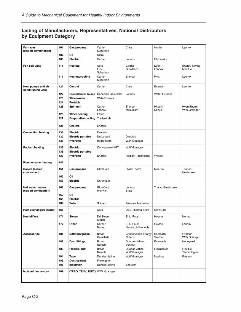
Page C-2
Listing of Manufacturers, Representatives, National Distributors by Equipment Category
A Guide to Mechanical Equipment for Healthy Indoor Environments
Furnaces 101 Gas/propane Carrier Clare Hunter Lennox (sealed combination) Suburban
102 Oil Clare
103 Electric Carrier Lennox Chromalox
Fan coil units 111 Heating Aero Carrier Delhi Energy SavingFirst GlowCore Lennox Mor-FloSuburban
112 Heating/cooling Carrier Enersol First LennoxSuburban
Heat pumps and air 121 Central Carrier Clare Enersol Lennox conditioning units
122 Ground/water source Canadian Geo-Solar Lennox Water Furnace
123 Water-water WaterFurnace
124 Portable
125 Split unit Carrier Enersol Hitachi HydroTherm Lennox Mitsubishi Sanyo W.W.Grainger
126 Water heating Etech
127 Evaporative cooling Tradewinds
128 Chillers Enersol
Convection heating 131 Electric Fantech
132 Electric portable De Longhi Dimplex
133 Hydronic Hydrotherm W.W.Grainger
Radiant heating 135 Electric Convectaire-NMT W.W.Grainger
136 Electric portable
137 Hydronic Enersol Radiant Technology Wirsbo
Passive solar heating 141
Boilers (sealed 151 Gas/propane GlowCore HydroTherm Mor-Flo Trianco-combustion) Heatmaker
152 Oil
153 Electric Chromalox
Hot water heaters 161 Gas/propane GlowCore Lennox Trianco-Heatmaker (sealed combustion) Mor-Flo State
162 Oil
163 Electric
164 Solar Solcan Trianco-Heatmaker
Heat exchangers (water) 165 Aero DEC Therma Store GlowCore
Humidifiers 171 Steam Dri-Steem E. L. Foust Hoyme NortecSkuttle
172 Other Carrier E. L. Foust Hoyme LennoxNortec Research Products
Accessories 181 Diffmors/grilles Broan Conservation Energy Eneready FantechKanalflakt Nutech Venmar W.W.Grainger
182 Duct fittings Broan Dundas-Jafine Eneready HoneywellNutech Venmar
183 Flexible duct Broan Dundas-Jafine Flexmaster Flexible Nutech W.W.Grainger Technologies
184 Tape Dundas-Jafine W.W.Grainger Nashua Polyken
185 Duct sealant Flexmaster
186 Insulation Dundas-Jafine Schuller
Isolated fan motors 189 (TEAO, TENV, TEFC) W.W. Grainger
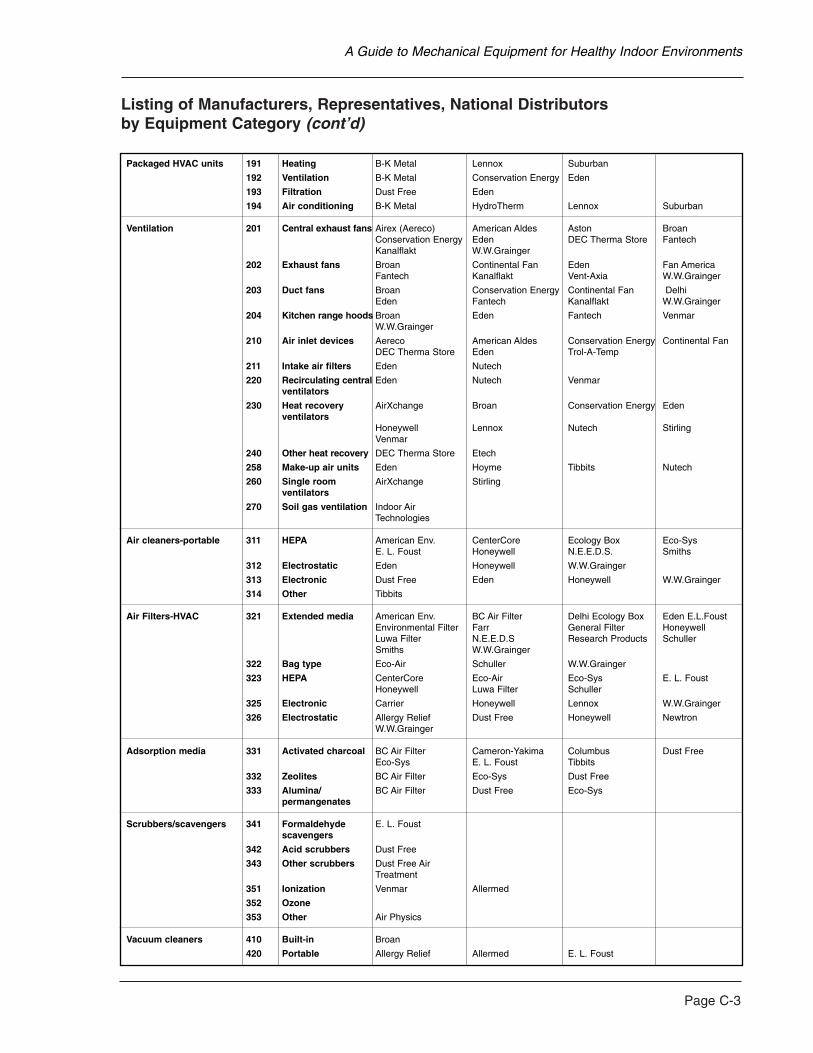
Listing of Manufacturers, Representatives, National Distributors by Equipment Category (cont’d)
Page C-3
A Guide to Mechanical Equipment for Healthy Indoor Environments
Packaged HVAC units 191 Heating B-K Metal Lennox Suburban
192 Ventilation B-K Metal Conservation Energy Eden
193 Filtration Dust Free Eden
194 Air conditioning B-K Metal HydroTherm Lennox Suburban
Ventilation 201 Central exhaust fans Airex (Aereco) American Aldes Aston BroanConservation Energy Eden DEC Therma Store FantechKanalflakt W.W.Grainger
202 Exhaust fans Broan Continental Fan Eden Fan America Fantech Kanalflakt Vent-Axia W.W.Grainger
203 Duct fans Broan Conservation Energy Continental Fan Delhi Eden Fantech Kanalflakt W.W.Grainger
204 Kitchen range hoods Broan Eden Fantech VenmarW.W.Grainger
210 Air inlet devices Aereco American Aldes Conservation Energy Continental Fan DEC Therma Store Eden Trol-A-Temp
211 Intake air filters Eden Nutech
220 Recirculating central Eden Nutech Venmar ventilators
230 Heat recovery AirXchange Broan Conservation Energy Edenventilators
Honeywell Lennox Nutech StirlingVenmar
240 Other heat recovery DEC Therma Store Etech
258 Make-up air units Eden Hoyme Tibbits Nutech
260 Single room AirXchange Stirling ventilators
270 Soil gas ventilation Indoor Air Technologies
Air cleaners-portable 311 HEPA American Env. CenterCore Ecology Box Eco-Sys E. L. Foust Honeywell N.E.E.D.S. Smiths
312 Electrostatic Eden Honeywell W.W.Grainger
313 Electronic Dust Free Eden Honeywell W.W.Grainger
314 Other Tibbits
Air Filters-HVAC 321 Extended media American Env. BC Air Filter Delhi Ecology Box Eden E.L.FoustEnvironmental Filter Farr General Filter HoneywellLuwa Filter N.E.E.D.S Research Products Schuller Smiths W.W.Grainger
322 Bag type Eco-Air Schuller W.W.Grainger
323 HEPA CenterCore Eco-Air Eco-Sys E. L. FoustHoneywell Luwa Filter Schuller
325 Electronic Carrier Honeywell Lennox W.W.Grainger
326 Electrostatic Allergy Relief Dust Free Honeywell Newtron W.W.Grainger
Adsorption media 331 Activated charcoal BC Air Filter Cameron-Yakima Columbus Dust Free Eco-Sys E. L. Foust Tibbits
332 Zeolites BC Air Filter Eco-Sys Dust Free
333 Alumina/ BC Air Filter Dust Free Eco-Syspermangenates
Scrubbers/scavengers 341 Formaldehyde E. L. Foust scavengers
342 Acid scrubbers Dust Free
343 Other scrubbers Dust Free Air Treatment
351 Ionization Venmar Allermed
352 Ozone
353 Other Air Physics
Vacuum cleaners 410 Built-in Broan
420 Portable Allergy Relief Allermed E. L. Foust
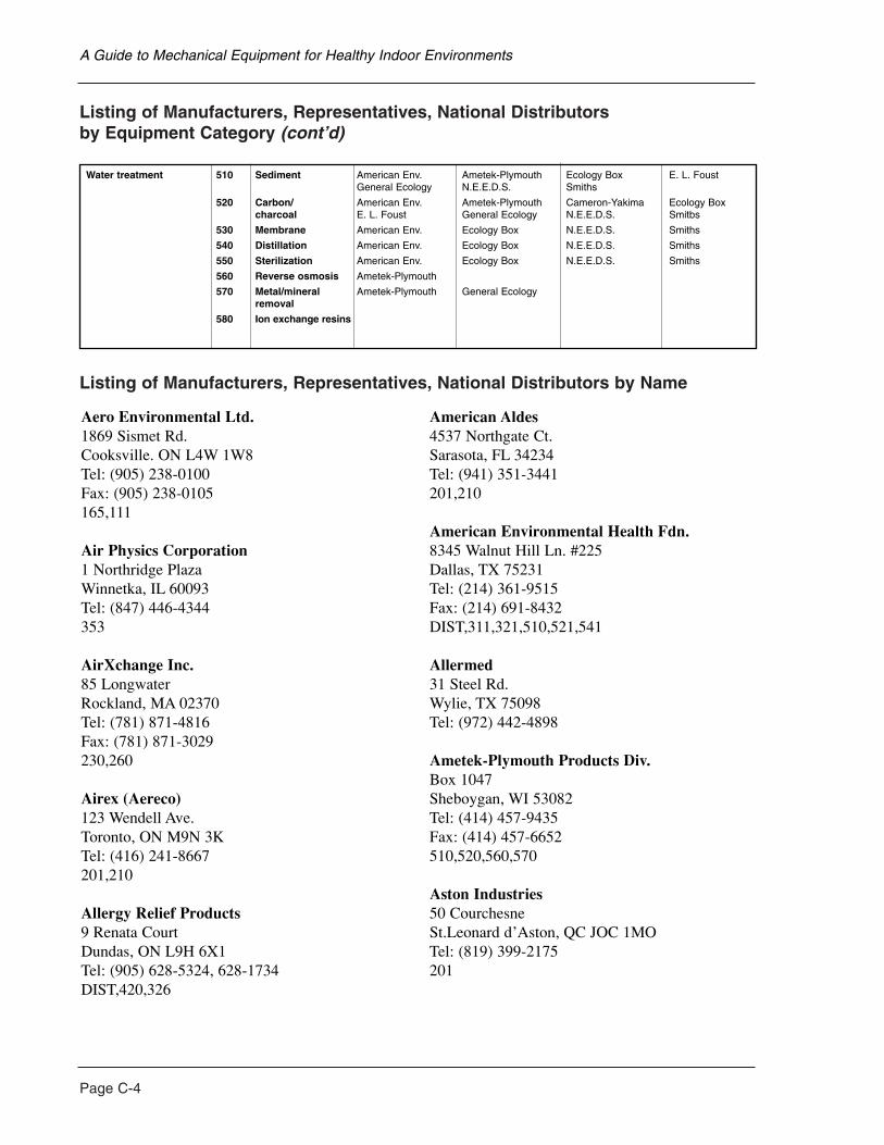
Page C-4
Listing of Manufacturers, Representatives, National Distributors by Equipment Category (cont’d)
Listing of Manufacturers, Representatives, National Distributors by Name
A Guide to Mechanical Equipment for Healthy Indoor Environments
Water treatment 510 Sediment American Env. Ametek-Plymouth Ecology Box E. L. FoustGeneral Ecology N.E.E.D.S. Smiths
520 Carbon/ American Env. Ametek-Plymouth Cameron-Yakima Ecology Boxcharcoal E. L. Foust General Ecology N.E.E.D.S. Smitbs
530 Membrane American Env. Ecology Box N.E.E.D.S. Smiths
540 Distillation American Env. Ecology Box N.E.E.D.S. Smiths
550 Sterilization American Env. Ecology Box N.E.E.D.S. Smiths
560 Reverse osmosis Ametek-Plymouth
570 Metal/mineral Ametek-Plymouth General Ecologyremoval
580 Ion exchange resins
Aero Environmental Ltd.1869 Sismet Rd.Cooksville. ON L4W 1W8Tel: (905) 238-0100Fax: (905) 238-0105 165,111
Air Physics Corporation1 Northridge PlazaWinnetka, IL 60093Tel: (847) 446-4344353
AirXchange Inc.85 LongwaterRockland, MA 02370Tel: (781) 871-4816Fax: (781) 871-3029 230,260
Airex (Aereco)123 Wendell Ave.Toronto, ON M9N 3KTel: (416) 241-8667201,210
Allergy Relief Products9 Renata CourtDundas, ON L9H 6X1Tel: (905) 628-5324, 628-1734DIST,420,326
American Aldes4537 Northgate Ct.Sarasota, FL 34234Tel: (941) 351-3441201,210
American Environmental Health Fdn.8345 Walnut Hill Ln. #225Dallas, TX 75231Tel: (214) 361-9515Fax: (214) 691-8432 DIST,311,321,510,521,541
Allermed31 Steel Rd.Wylie, TX 75098Tel: (972) 442-4898
Ametek-Plymouth Products Div.Box 1047Sheboygan, WI 53082Tel: (414) 457-9435Fax: (414) 457-6652 510,520,560,570
Aston Industries50 CourchesneSt.Leonard d’Aston, QC JOC 1MOTel: (819) 399-2175201
BC Air Filter2809 Norland Ave.Burnaby, BC V5B 3A9Tel: (604) 291-2554321,331,332
Broan Canada Ltd.1140 Tistar Dr.Mississauga, ON L5T 1H9Tel: (905) 670-2500, 678-2251201,202,203,204,230,183,182,181,410
B-K Metal Supplies Ltd.1050 Ellias St.London, ON N5W 3P6Tel: (519) 659-4666Fax: (519) 659-4683 191,192,194
Cameron-Yakima Inc.720 Valley Mall BoulevardYakima,WA 98903Tel: (509) 452-6605Fax: (509) 453-9912 331,520
Canadian Geo-Solar640 Gartshore Rd.Fergus, ON N1M 2W8Tel: (519) 843-3393Fax: (519) 843-6944 122
Carrier Canada200-1900 Minnesota CourtMississauga, ON L5N 5RSTel: (905) 826-9508Fax: (905) 826-2349 101,103,111,112,121,125,172,325
CentreCore Canada Inc.6725 Millcreek Dr.Mississauga, ON L5N 5V3Tel: (905) 542-7661Fax: (905) 542-7662 311,323
Clare Brothers Limited675 Davenport RoadKitchener, ON N2V 2E2Tel: (519) 725-1854101,102,121
Columbus Industries2938 Rt 752Ashville, OH 43103Tel: (614) 983-2552331
Conservation Energy Systems2525 Wentz Ave.Saskatoon, SK S7K 2K9Tel: (306) 242-3663Fax: (306) 242-3484 201,203,210,230,192,181,182,183
Continental Fan Mfg. Inc.205 Matheson Blvd. E.Cooksville, ON L4Z 3E3Tel: (905) 890-6887Fax: (905) 890-6193 210,202,203
Convectaire-NMT Inc.30 Place SicardSt-Therese, QC J7E 3X6Tel: (514) 433-5701, 434-3166135
DeLonghi5425 Dixie Rd., Rm 201Mississauga, ON L4W 1E6Tel: (905) 238-1957132
DEC Therma Store2001 Stoughton RoadMadison, WI 53716Tel: (608) 222-5301201,240,165,210
Delhi Industries Inc.83 ShaverBrantford, ON N4B 2Z3Tel: (519) 752-0311, 582-0581203,111,321
Page C-5
A Guide to Mechanical Equipment for Healthy Indoor Environments
Page C-6
Dri-Steem Humidifier Co.14949 Technology Dr.Eden Prairie, MN 55344Tel: (612) 949-2415, 949-2933171
Dundas-Jafine Inc.80 West Dr.Brampton, ON L6T 3T6Tel: (905) 450-7200Fax: (905) 450-7207 182,183,184,186
Dust Free Inc.1112 Industrial Dr.Royse City, TX 75189Tel: (972) 635-9564Fax: (972) 635-7972 326,331,313,193
Eco-Air Products Inc.9455 Cabot Dr.San Diego, CA 92126Tel: (619) 271-8111Fax: (619) 578-8316 322,323
Eco-Sys Ltd.2777C Innes Rd.Ottawa, ON K1B 3J7Tel: (613) 841-0190311,323,332,331,333
Ecology Box308 Oak TreeClinton, MI 49236Tel: (517) 456-4188DIST,311,321,510,520,550
Eden Energy Equipment71 Wyndham St. SGuelph, ON N1E 5R3Tel: (519) 821-8478Fax: (519) 821-8491 DIST,201,202,203,204,210,211,220,230,258,321,312,313,192,193
Eneready Products Ltd.6860 Antrim Ave.Burnaby, BC V5J 4M4Tel: (604) 433-5697Fax: (604) 438-8906DIST,181,182
Energy Saving Products Ltd.12615-124 StreetEdmonton, AL T5L 0N8Tel: (403) 453-2093Fax: (403) 435-1932 111
Enersol Inc.1655 de l’industrieBeloeil, QC J3G 4S5Tel: (514) 464-4545Fax: (514) 464-5563 112,121,125,128.137
Environmental Filter Corp.265 Roberts Ave.Santa Rosa, CA 95407Tel: (707) 525-8633321
Etech3040 Holcomb Bridge Road NWNorcross, GA 30071Tel: (770) 825-0535240,126
E.L. Foust Co. Inc.Industrial DriveElmhurst, IL 60126Tel: (630) 834-4952Fax: (630) 834-5341420,331,323,311,172,171,321,341,510,520
Fan America Inc.1748 Independence Blvd.Sarasota, FL 34234Tel: (941) 359-3616Fax: (941) 359-3523 202
A Guide to Mechanical Equipment for Healthy Indoor Environments
Fantech Inc.1712 Northgate Blvd.Sarasota, FL 34234Tel: (941) 351-2947Fax: (941) 487-9951 131,201,202,203,204,181
Farr Co.2221 Park PlaceEl Segundo, CA 90245Tel: (310) 536-0606321,323
First Co.8273 Moberly LaneDallas, TX 75227Tel: (214) 388-5751Fax: (214) 388-2255 111,121
Flexmaster Canada Ltd.20 West Pearce St.Thornhill, ON L4B 1E3Tel: (905) 731-9411Fax: (905) 731-7086183,185
Flexible Technologies1630 Matheson Blvd.Cooksville, ON L4W 1Y4Tel: (905) 602-9660Fax: (905) 602-9665 183
General Ecology Inc.151 Sheree Blvd.Exton, PA 19341Tel: (620) 363-7900Fax: (620) 363-0412 510,520,570
General Filters Inc.43800 Grand River Ave.Novi, MI 48375Tel: (810) 349-2488Fax: (810) 349-2366321
GlowCore Canada140 Sydney St. S.Kitchener, ON N2G 4J1Tel: (519) 571-0036Fax: (519) 579-5730151,161,165,111
Hitachi (HSC) Canada Inc.6740 Capobello Rd.Streetsville, ON L5N 2L8Tel: (905) 821-4545125
Honeywell Ltd.115 Gordon Baker RoadToronto, ON M2H 2N7Tel: (416) 502-5200182,230,311,312,313,321,325,326
Hoyme Manufacturing Inc.3843 44th Ave.Camrose, AB T4V 3T1Tel: (403) 672-6553Fax: (403) 672-6554 258,171,172
Hunter Energy&Technologies Inc.100 Hunter Vallley Rd.Orillia, ON L3V 1T4Tel: (705) 325-6111Fax: (705) 327-5658 102,101
HydroTherm Canada Corp.5211 CreekbankCooksville, ON L4W 1R3Tel: (905) 625-2991Fax: (905) 625-6610 151,165,194,125
Indoor Air Technologies Inc.2344 Haddington Crt.Ottawa, ON K1N 8J4Tel: (613) 731-2559Fax: (613) 731-2559 270
Page C-7
A Guide to Mechanical Equipment for Healthy Indoor Environments
Page C-8
Kanalflakt Inc.50 Kanalflakt Way, P.O. Box 2000Bouctouche, NB E0A 1G0Tel: (506) 743-9500Fax: (506) 743-9600201,202,203,181
Lennox Industries Canada Ltd.400 Norris Glen Rd.Etobicoke, ON M9C 1H5Tel: (416) 621-9302Fax: (416) 621-6303101,103,111,112,121,122,125,161,172,191,194,230,325
Luwa Filter Corp.401 Hanks Ave.Aurora, IL 60505Tel: (630) 906-2100321,323
Mitsubishi Electric Canada Inc.4299 Fourteenth Unionville, ON L3R 5G1Tel: (905) 475-7728Fax: (905) 475-7861 125
N.E.E.D.S.527 Charles Ave. 12ASyracuse, NY 13209Tel: (315) 488-6300Fax: (315) 488-6336 DIST,311,321,510,520,540
Newtron Products3874 Virginia Ave.Cincinnati, OH 45227Tel: (513) 561-7373326
Nortec Air Conditioning Ind. Ltd.2740 Fenton Rd.Gloucester, ON K1T 3T7 Tel: (613) 822-0335171,172
Nutech Energy Systems Inc.511 McCormick Blvd.London, ON N5W 4C8Tel: (519) 457-1904Fax: (519) 457-1676 181,182,183,211,220,230
Radiant Technology Inc.11 Farber DriveBellport, NY 11713Tel: (516) 286-0900, 286-0947137
Research Products Corp.Box 1467Madison, WI 53701Tel: (608) 257-8801Fax: (608) 257-4357 172,321
Sanyo Canada Inc.50 Beth Nealson DriveToronto, ON M4H 1M6Tel: (416) 421-8344Fax: (416) 421-8827125
Schuller International Inc.Box 5108Denver, CO 80217Tel: (303) 978-2000186,321,322,323
Skuttle Mfg. Co.Box 51Marietta, OH 45750Tel: (614) 373-9169, 373-9565171,172
Smiths Pharmacy3463 Yonge St.Toronto, ON M2N 2N3Tel: (416) 488-2600Fax: (416) 484-8855DIST,311,321,510,520,530
A Guide to Mechanical Equipment for Healthy Indoor Environments
Solcan126 Wynchwood ParkLondon, ON N6G 1R7Tel: (519) 473-0501164
State Industries Inc.500 Bypass Rd.Ashland City, TN 37015Tel: (615) 792-4371161
Stirling Technology Inc.Box 2633Athens, OH 45701Tel: (740) 594-2277Fax: (740) 594-1499 230,260
Suburban Distribution Ltd.3096 Devon Dr.Windsor, ON N8X 4L2Tel: (519) 969-1152101,111,112,191,194
Tibbits Clean Air Machine Corp.Box 1016Cobourg, ON K9A 4W4Tel: (905) 372-7082Fax: (905) 372-8853 314,321,331,258
Tradewinds Technologies Inc.616 S. 55th Ave.Phoenix, AZ 85043Tel: (602) 278-1957Fax: (602) 272-9544 127
Trianco-Heatmaker111 York Ave.Randolph, MA 02368Tel: (617) 961-1660Fax: (617) 986-9907 151,161,165
Trol-A-Temp Ltd.55 Bushes LaneElmwood Park, NJ 07407Tel: (201) 794-8004210
Venmar Ventilation 550 Lemire BoulevardDrummondville, QC J2C 7W9Tel: (819) 477-6226Fax: (819) 475-2660 181,182,204,220,230,351
W.W. Grainger Inc.50 McKesson ParkwayBuffalo, NY 14225Tel: (716) 684-1000Fax: (716) 681-5334 DIST,189,135,133,183,184,181,125,313,312,321,325,326,322,323,201,202,203,204
Water-Furnace Inc.RR#1Mount Brydges, ON N8H 1P1Tel: (519) 264-1585122,123
Wirsbo Company5925 148 St.W.Apple Valley, MN 55124Tel: (612) 891-2000Fax: (612) 891-2008 137
Page C-9
A Guide to Mechanical Equipment for Healthy Indoor Environments

6201
5
20/06/05
Visit our home page at www.cmhc.ca