a guidance and obstacle evasion software framework for visually impaired …dkoester/... ·...
TRANSCRIPT

A Guidance and Obstacle Evasion
Software Framework for Visually
Impaired People
Diploma thesis of
Daniel Koester
At the faculty of Computer Science
Institute for Anthropomatics
Reviewer: Prof. Dr.-Ing. Rainer Stiefelhagen
Second reviewer: Prof. Dr.-Ing. Rüdiger Dillmann
Advisor: Dipl.-Inform. Boris Schauerte
Duration: 1. August 2012 – 31. January 2013
KIT – University of the State of Baden-Wuerttemberg and National Laboratory of the Helmholtz Association www.kit.edu

Computer Vision for Human-Computer Interaction Research GroupInstitute for AnthropomaticsKarlsruhe Institute of TechnologyTitle: A Guidance and Obstacle Evasion Software Framework for Visually Impaired PeopleAuthor: Daniel Koester
Daniel KoesterBernhardstraße 2176131 [email protected]
ii

Statement of Authorship
I hereby declare that this thesis is my own original work which I created without illegitimatehelp by others, that I have not used any other sources or resources than the ones indicatedand that due acknowledgement is given where reference is made to the work of others.
Karlsruhe, 31. January 2013 . . . . . . . . . . . . . . . . . . . . . . . . . . . . . . . . . . . . . . . . . . . .(Daniel Koester)
iii

Abstract
Information about the environment is desired in several applications, for example au-tonomous robots and support systems for visually impaired persons. Like with mostscenarios where a human being uses a support system, reliability is of utmost importance.This creates a high demand for performance and robustness in real-world settings. Manysystems created towards this purpose cannot cope with constraints such as platforms witha large amount of uncontrolled ego-motion and the need for real-time processing of infor-mation and are thus not feasible for this specific situation.
The topic of this thesis is a novel framework to create vision based support systems forvisually impaired persons. It consists of a modular, easily extendable and highly agilesoftware system. Furthermore, a ground detection system is created to aid in mobilenavigation scenarios. The system calculates the accessible section by relying on the as-sumption that the orientation of a given plane segment can be calculated using a stereocamera reconstruction process.
Many frameworks have been created to simplify the developing process of large and com-plex systems and to foster collaboration among researchers. Usually, such frameworkswould be created towards a certain purpose, for example a robotic application. In such ascenario, many elements are needed to manage the components of the robotic platform,such as motor controls. This creates dependencies on the availability of specific buildingblocks and induce great overhead if such components are not needed. Thus, the createdframework imposes no restrictions on its use case by moving such functionality into mod-ular components.
In computer vision many features and algorithms to detect ground plane exist. Some ofthese are quite costly to calculate, for example segmentation based algorithms. Others usea random sample consensus (RANSAC) based approach that shows problems in situationswhere the existing ground plane only accounts for a small part of the examined inputdata. To alleviate these problems a simple, yet robust, feature is proposed which consistsof a gradient detection in the stereo reconstruction data. The gradient of a region in thedisparity map correlates directly with the orientation of a surface in the real world. Sincethe gradient calculation is not complex, a fast and reliable computation of the accessiblesection becomes possible.
To evaluate the proposed ground detection system, a dataset was created. This datasetconsists of 20 videos recorded with a hand held camera rig and contains a high degreeof camera ego-motion to simulate a system worn by a pedestrian. The accessible sectiondetection based on the gradient calculation shows promising results.
v


Kurzbeschreibung
Informationen uber die nahere Umgebung sind in den verschiedensten Anwendungsfallensehr begehrt, zum Beispiel fur autonome Roboter und unterstutzende Systeme fur Blindeund sehbehinderte Menschen. Wie in den meisten Szenarien, in denen sich der Menschauf ein unterstutzendes System verlasst, ist Zuverlassigkeit ein entscheidender Faktor.Diese Tatsache stellt hohe Anforderungen an Performanz und Robustheit unter realenBedingungen. Viele Systeme die zu diesem Zweck erstellt wurden weisen Probleme auf,welche durch die Verwendung von mobilen Plattformen mit einer starken Eigenbewegungsowie der Erfordernis an echtzeitfahiger Verarbeitung entstehen. Sie sind daher in solchspezifischen Situationen nicht verwendbar.
Der Schwerpunkt dieser Arbeit liegt auf einem neuartigen Software Framework fur die bild-basierte Unterstutzung von Blinden oder sehbehinderten Menschen. Es besteht aus einemmodularen, einfach zu erweiternden und hochst agilem Software System. Weiterhin wirdeine Methode zur Erkennung der begehbaren Flache zur Hilfe bei der mobilen Orientierungeiner Person erstellt. Dieses System ermittelt die begehbare Flache basierend auf derAnnahme, dass die Ausrichtung eines Flachenabschnittes aus den gewonnen Daten einerStereo Rekonstruktion berechnet werden kann.
Viele Software Frameworks wurden bereits erstellt um den Entwicklungsprozess von großenund komplexen System zu vereinfachen und um die Zusammenarbeit zwischen Forschernvoranzutreiben. Normalerweise werden solche Software Frameworks zu einem bestimmtenZweck erstellt, zum Beispiel der Steuerung eines Roboters. In solch einer Umgebungwerden viele Elemente gebraucht und die verschiedensten Komponenten einer solchenRobotik-Plattform anzusprechen, z.B. Motor Steuerungen. Dies kann eine Abhangigkeitzu spezifischen Bestandteilen erzeugen und damit einen Mehraufwand hervorrufen, solltensolche Komponenten nicht gebraucht werden. Daher wurde das Framework so erstellt, dasses keinerlei Einschrankungen an sein Benutzungsszenario stellt, indem jegliche derartigeFunktionalitat ausgelagert wird.
In der Bild-Verarbeitung existieren bereits viele Algorithmen zur Bestimmung der Bo-denflache. Manche dieser Algorithmen sind sehr aufwendig zu berechnen, zum BeispielSegmentierungen. Andere benutzen einen random sample consensus (RANSAC) basiertenAnsatz, welcher Probleme aufzeigt, wenn die zu erkennende Bodenflache nur einen kleinenTeil der zu untersuchenden Daten ausmacht. Um solche Probleme zu vermeiden, wird eineinfaches, jedoch robustes, Merkmal vorgestellt, welches auf der Berechnung eines Gradien-tens in einer Stereo Rekonstruktion basiert. Dabei lasst sich feststellen, dass der Gradienteiner untersuchten Region der Stereo Rekonstruktion mit der Ausrichtung einer Flache inder realen Welt korreliert. Da die Gradienten Berechnung nicht komplex ist, wird eineschnelle und zuverlassige Berechnung der begehbaren Sektion ermoglicht.
Um das erstellte System zu evaluieren, wurde ein Datensatz erstellt. Dieser Datensatzbesteht aus 20 Videos, welche mit einer handgefuhrten Kameraanlage aufgenommen wur-den. Die Videos enthalten einen hohen Grad an Eigenbewegung der Kameras um ein trag-bares System zu simulieren. Die Bodenerkennung basierend auf der Gradienten Berech-nung zeigt hierbei verheißungsvolle Ergebnisse.
vii

Contents
1. Introduction 1
1.1. Motivation . . . . . . . . . . . . . . . . . . . . . . . . . . . . . . . . . . . . 2
1.2. Contributions . . . . . . . . . . . . . . . . . . . . . . . . . . . . . . . . . . . 4
1.3. Outline . . . . . . . . . . . . . . . . . . . . . . . . . . . . . . . . . . . . . . 4
2. Related Work 7
2.1. Navigational Aids for Visually Impaired People . . . . . . . . . . . . . . . . 7
2.2. Frameworks . . . . . . . . . . . . . . . . . . . . . . . . . . . . . . . . . . . . 9
2.2.1. Robotic Operating System . . . . . . . . . . . . . . . . . . . . . . . 9
2.2.2. Player 2.0 . . . . . . . . . . . . . . . . . . . . . . . . . . . . . . . . . 10
2.2.3. Distributed Augmented Reality Framework . . . . . . . . . . . . . . 10
2.3. Ground Plane and Obstacle Detection . . . . . . . . . . . . . . . . . . . . . 11
2.3.1. Plane Fitting . . . . . . . . . . . . . . . . . . . . . . . . . . . . . . . 11
2.3.2. Segmentation . . . . . . . . . . . . . . . . . . . . . . . . . . . . . . . 12
2.3.3. Obstacles . . . . . . . . . . . . . . . . . . . . . . . . . . . . . . . . . 12
3. The Blind and Visually Impaired Support System 15
3.1. Main Design Goals . . . . . . . . . . . . . . . . . . . . . . . . . . . . . . . . 15
3.2. Public Interfaces . . . . . . . . . . . . . . . . . . . . . . . . . . . . . . . . . 17
3.2.1. Client Interface . . . . . . . . . . . . . . . . . . . . . . . . . . . . . . 17
3.2.2. Module Interface . . . . . . . . . . . . . . . . . . . . . . . . . . . . . 19
3.2.3. Module Connectors . . . . . . . . . . . . . . . . . . . . . . . . . . . . 19
3.2.4. Configuration Subsystem . . . . . . . . . . . . . . . . . . . . . . . . 20
3.2.5. Logging Subsystem . . . . . . . . . . . . . . . . . . . . . . . . . . . . 22
3.2.6. System Information . . . . . . . . . . . . . . . . . . . . . . . . . . . 23
3.3. Private Interfaces . . . . . . . . . . . . . . . . . . . . . . . . . . . . . . . . . 23
3.3.1. Loader . . . . . . . . . . . . . . . . . . . . . . . . . . . . . . . . . . . 23
3.3.2. Control . . . . . . . . . . . . . . . . . . . . . . . . . . . . . . . . . . 24
3.4. Base Modules . . . . . . . . . . . . . . . . . . . . . . . . . . . . . . . . . . . 25
3.4.1. Capture Module . . . . . . . . . . . . . . . . . . . . . . . . . . . . . 25
3.4.2. Calibration Module . . . . . . . . . . . . . . . . . . . . . . . . . . . 26
3.4.3. Stereo Vision Module . . . . . . . . . . . . . . . . . . . . . . . . . . 26
3.5. Additional Tools . . . . . . . . . . . . . . . . . . . . . . . . . . . . . . . . . 26
ix

Contents
4. The Ground Detection System 29
4.1. Design . . . . . . . . . . . . . . . . . . . . . . . . . . . . . . . . . . . . . . . 294.1.1. System Description . . . . . . . . . . . . . . . . . . . . . . . . . . . . 294.1.2. Efficient Large-scale Stereo Matching . . . . . . . . . . . . . . . . . . 304.1.3. Gradient Calculation . . . . . . . . . . . . . . . . . . . . . . . . . . . 314.1.4. Accessible Section . . . . . . . . . . . . . . . . . . . . . . . . . . . . 33
4.2. The Flower-Box Dataset . . . . . . . . . . . . . . . . . . . . . . . . . . . . . 334.2.1. Acquisition . . . . . . . . . . . . . . . . . . . . . . . . . . . . . . . . 344.2.2. Labeling Process . . . . . . . . . . . . . . . . . . . . . . . . . . . . . 34
4.3. Evaluation . . . . . . . . . . . . . . . . . . . . . . . . . . . . . . . . . . . . . 384.4. Results . . . . . . . . . . . . . . . . . . . . . . . . . . . . . . . . . . . . . . . 40
5. Conclusion 49
5.1. Future Work . . . . . . . . . . . . . . . . . . . . . . . . . . . . . . . . . . . 50
Bibliography 53
Appendix 57
A. BVS System Overview . . . . . . . . . . . . . . . . . . . . . . . . . . . . . . 57
x

List of Figures
1.1. A visually impaired person crossing a street . . . . . . . . . . . . . . . . . . 21.2. Subaru’s EyeSight System . . . . . . . . . . . . . . . . . . . . . . . . . . . . 3
2.1. The GuideCane housing and wheelbase . . . . . . . . . . . . . . . . . . . . . 82.2. Aerial obstacle detection . . . . . . . . . . . . . . . . . . . . . . . . . . . . . 92.3. Distributed Wearable Augmented Reality Framework . . . . . . . . . . . . . 112.4. Close Range Human Detection for Head Mounted Cameras . . . . . . . . . 12
3.1. An overview of the framework . . . . . . . . . . . . . . . . . . . . . . . . . . 153.2. Configuration subsystem syntax . . . . . . . . . . . . . . . . . . . . . . . . . 213.3. Module configuration syntax . . . . . . . . . . . . . . . . . . . . . . . . . . 223.4. Overview of logging levels . . . . . . . . . . . . . . . . . . . . . . . . . . . . 23
4.1. A framework configuration example . . . . . . . . . . . . . . . . . . . . . . 304.2. Results of the ELAS stereo reconstruction . . . . . . . . . . . . . . . . . . . 314.3. Disparity map mockup . . . . . . . . . . . . . . . . . . . . . . . . . . . . . . 324.4. Flower-Box dataset video list . . . . . . . . . . . . . . . . . . . . . . . . . . 354.5. Flower-Box dataset videos part I/II . . . . . . . . . . . . . . . . . . . . . . 364.6. Flower-Box dataset videos part II/II . . . . . . . . . . . . . . . . . . . . . . 374.7. Confusion matrix . . . . . . . . . . . . . . . . . . . . . . . . . . . . . . . . . 384.8. Prediction classes example . . . . . . . . . . . . . . . . . . . . . . . . . . . . 394.9. Good recognition examples . . . . . . . . . . . . . . . . . . . . . . . . . . . 414.10. Bad recognition examples . . . . . . . . . . . . . . . . . . . . . . . . . . . . 424.11. Low recognition scores caused by failing stereo reconstruction . . . . . . . . 434.12. Flower-Box dataset video results part I/II . . . . . . . . . . . . . . . . . . . 444.13. Flower-Box dataset video results part II/II . . . . . . . . . . . . . . . . . . 454.14. Flower-Box dataset result overview . . . . . . . . . . . . . . . . . . . . . . . 464.15. Flower-Box dataset result standard deviation . . . . . . . . . . . . . . . . . 47
A.1. The main interfaces . . . . . . . . . . . . . . . . . . . . . . . . . . . . . . . 57A.2. The logging system backend . . . . . . . . . . . . . . . . . . . . . . . . . . . 58A.3. The control and loader relationship . . . . . . . . . . . . . . . . . . . . . . . 59
xi

List of Abbreviations
ARToolKit augmented reality toolkit. . . . . . . . . . . . . . . . . . . . . . . . . . . . . . . . . . . . . . . . . . . . . . . . .10AR augmented reality . . . . . . . . . . . . . . . . . . . . . . . . . . . . . . . . . . . . . . . . . . . . . . . . . . . . . . . . 10AUC area under the curve . . . . . . . . . . . . . . . . . . . . . . . . . . . . . . . . . . . . . . . . . . . . . . . . . . . . . 38BVS blind and visually impaired support systemCARMEN carnegie mellon navigation toolkit . . . . . . . . . . . . . . . . . . . . . . . . . . . . . . . . . . . . . . . . . 9CMake cross-platform make . . . . . . . . . . . . . . . . . . . . . . . . . . . . . . . . . . . . . . . . . . . . . . . . . . . . . . 17CPU central processing unit . . . . . . . . . . . . . . . . . . . . . . . . . . . . . . . . . . . . . . . . . . . . . . . . . . . 10DTAM dense tracking and mapping . . . . . . . . . . . . . . . . . . . . . . . . . . . . . . . . . . . . . . . . . . . . . . 51DWARF distributed wearable augmented reality framework . . . . . . . . . . . . . . . . . . . . . . . . . 9ELAS efficient large-scale stereo matching. . . . . . . . . . . . . . . . . . . . . . . . . . . . . . . . . . . . . . .30GPS global positioning system. . . . . . . . . . . . . . . . . . . . . . . . . . . . . . . . . . . . . . . . . . . . . . . . . . 7GPU graphics processing unit . . . . . . . . . . . . . . . . . . . . . . . . . . . . . . . . . . . . . . . . . . . . . . . . . . 26GUI graphical user interface. . . . . . . . . . . . . . . . . . . . . . . . . . . . . . . . . . . . . . . . . . . . . . . . . . .50IMU inertial measurement unit . . . . . . . . . . . . . . . . . . . . . . . . . . . . . . . . . . . . . . . . . . . . . . . . . 8IPC inter-process communication . . . . . . . . . . . . . . . . . . . . . . . . . . . . . . . . . . . . . . . . . . . . . 10IRLS iteratively reweighted least-squares . . . . . . . . . . . . . . . . . . . . . . . . . . . . . . . . . . . . . . . 11LIDAR light detection and ranging . . . . . . . . . . . . . . . . . . . . . . . . . . . . . . . . . . . . . . . . . . . . . . . . 1MATLAB matrix laboratory . . . . . . . . . . . . . . . . . . . . . . . . . . . . . . . . . . . . . . . . . . . . . . . . . . . . . . . . 34OpenCV open source computer vision library . . . . . . . . . . . . . . . . . . . . . . . . . . . . . . . . . . . . . . . 9PR precision-recall . . . . . . . . . . . . . . . . . . . . . . . . . . . . . . . . . . . . . . . . . . . . . . . . . . . . . . . . . . . 38PTAM parallel tracking and mapping . . . . . . . . . . . . . . . . . . . . . . . . . . . . . . . . . . . . . . . . . . . . 51RANSAC random sample consensus . . . . . . . . . . . . . . . . . . . . . . . . . . . . . . . . . . . . . . . . . . . . . . . . . vRGB-D red-green-blue and depth . . . . . . . . . . . . . . . . . . . . . . . . . . . . . . . . . . . . . . . . . . . . . . . . . . 8RGB red-green-blue . . . . . . . . . . . . . . . . . . . . . . . . . . . . . . . . . . . . . . . . . . . . . . . . . . . . . . . . . . . . . 8ROC receiver operating characteristic . . . . . . . . . . . . . . . . . . . . . . . . . . . . . . . . . . . . . . . . . . 38ROS robot operating system . . . . . . . . . . . . . . . . . . . . . . . . . . . . . . . . . . . . . . . . . . . . . . . . . . . . 9RTTI run-time type information . . . . . . . . . . . . . . . . . . . . . . . . . . . . . . . . . . . . . . . . . . . . . . . . 20SLAM simultaneous localization and mapping . . . . . . . . . . . . . . . . . . . . . . . . . . . . . . . . . . . 51STOC stereo on chip . . . . . . . . . . . . . . . . . . . . . . . . . . . . . . . . . . . . . . . . . . . . . . . . . . . . . . . . . . . . 13TCP transmission control protocol . . . . . . . . . . . . . . . . . . . . . . . . . . . . . . . . . . . . . . . . . . . . . 10TOF time of flight . . . . . . . . . . . . . . . . . . . . . . . . . . . . . . . . . . . . . . . . . . . . . . . . . . . . . . . . . . . . . . 8UAV unmanned aerial vehicle . . . . . . . . . . . . . . . . . . . . . . . . . . . . . . . . . . . . . . . . . . . . . . . . . . . 1
xiii


Acknowledgements
I want to thank the people without whom my diploma thesis would not have been madepossible.
First, Rainer Stiefelhagen for the opportunity to write my thesis with his Computer Visionfor Human-Computer Interaction Lab (CVHCI), for letting me participate in his researcharea and allowing me to concentrate my efforts on topics very dear to my heart. I am verygrateful to Boris Schauerte for his interest in my diploma thesis topic, his support andguidance as well as his supervision and experience in all related matters. Furthermore, Iam proud that Rainer Stiefelhagen is giving me the chance to become a member of hisCVHCI lab. I suppose I also have to partially thank Boris for this opportunity, you are agreat mentor and I am sure, will become even more so in the future.
My thanks go to all the CVHCI members for their interesting discussions as well as valuableinput whenever problems arose. The supportive working atmosphere and the relocationto a new, much quieter facility, makes the CVHCI lab an amazing place to work in.
Many thanks and apologies go to my fellow lab students Matthias Lang and Timo Schneiderfor testing as well as using early prototypes of the created framework and creating bugs Icould never even imagine. I would also like to thank my very good friends Paul Margnerand Jan-Ole Sasse for proofreading, your corrections are much valued.
I want to thank my family for their support and encouragement throughout the years ofmy academic studies. Especially my parents and my sister, who are optometrists, followedmy diploma thesis with great interest. Their ongoing assistance has helped me greatly topursue this endeavor. I hope to make them proud and to show them my appreciation forall they have done for me.
Finally, I want to thank my girlfriend Nicole. Not only for her efforts put into countlesshours labeling the dataset with me, but especially for her love, support and care wheneverit was most needed. You make my day.
xv

1. Introduction
”Walking with a friend in the dark is better than walking alone in the light.”Helen Keller
Navigation in an unknown or known terrain has been an intensively researched topic for along time. It exists in several scientific domains, either directly related to computer visionor using computer vision as a means to gather such information, often in combination withother methods and sensors. A robot could search for a path in an unknown terrain. Anautomobile could not only scan for the existence of road, respectively lanes in front of thecar, but additionally try to warn the driver against pedestrians or other traffic participantsthat are getting in the way or too close to the vehicle. An unmanned aerial vehicle (UAV)could try to avoid collisions while being controlled remotely or flying autonomously. Avisually impaired person could simply search for a way to walk without colliding withmoving or static obstacles.
There already exists an entire array of techniques and specialized hardware to gatherinformation in an unknown surrounding, such as for example radar, sonar or light detectionand ranging (LIDAR). Most of these require elaborate, complex, obtrusive, bulky orexpensive hardware. Meanwhile, digital cameras and raw computing power have seen aconstant decrease in cost and size. This manifests itself in mobile smartphones whichhave become commonplace in our modern world. Computer vision can replace their moreexpensive counterparts and provide an inexpensive and mobile alternative for navigationalaid systems.
1
1. Introduction
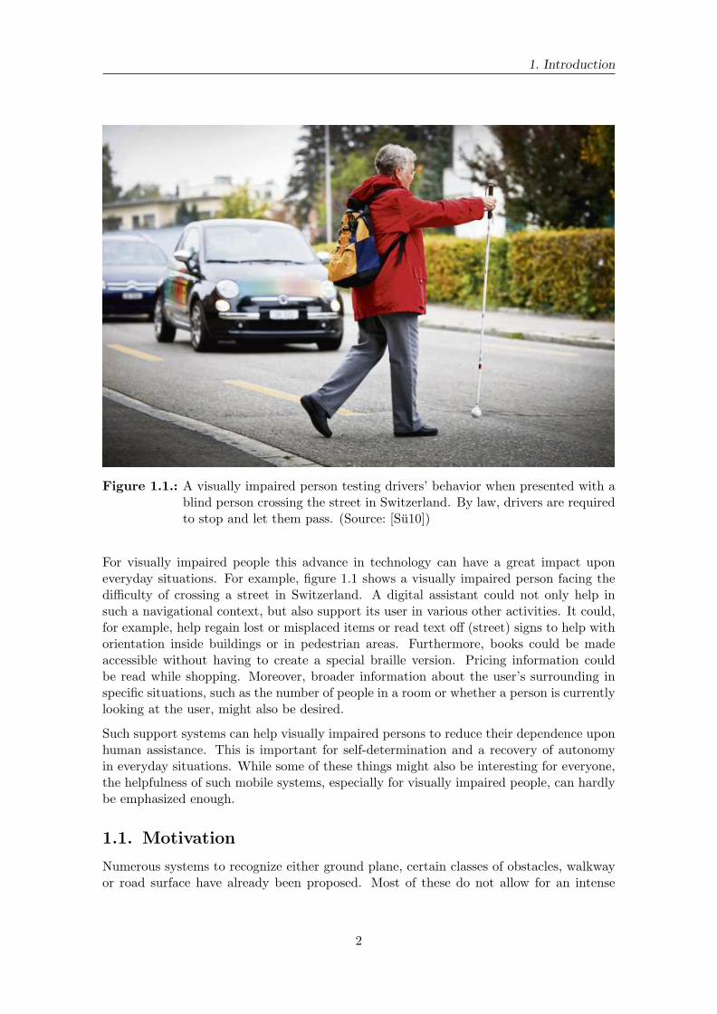
Figure 1.1.: A visually impaired person testing drivers’ behavior when presented with ablind person crossing the street in Switzerland. By law, drivers are requiredto stop and let them pass. (Source: [Su10])
For visually impaired people this advance in technology can have a great impact uponeveryday situations. For example, figure 1.1 shows a visually impaired person facing thedifficulty of crossing a street in Switzerland. A digital assistant could not only help insuch a navigational context, but also support its user in various other activities. It could,for example, help regain lost or misplaced items or read text off (street) signs to help withorientation inside buildings or in pedestrian areas. Furthermore, books could be madeaccessible without having to create a special braille version. Pricing information couldbe read while shopping. Moreover, broader information about the user’s surrounding inspecific situations, such as the number of people in a room or whether a person is currentlylooking at the user, might also be desired.
Such support systems can help visually impaired persons to reduce their dependence uponhuman assistance. This is important for self-determination and a recovery of autonomyin everyday situations. While some of these things might also be interesting for everyone,the helpfulness of such mobile systems, especially for visually impaired people, can hardlybe emphasized enough.
1.1. Motivation
Numerous systems to recognize either ground plane, certain classes of obstacles, walkwayor road surface have already been proposed. Most of these do not allow for an intense
2

1.1. Motivation
Figure 1.2.: Subaru’s EyeSight system can recognize pedestrians, cyclists and other carsto help drivers avoid collisions. It also triggers several active, passive andpreventive systems when hazards are detected. (Source: [Ste11])
camera movement and have so far been used in rather static settings such as upon slowlymoving robots. This is due to the fact that they impose constraints upon the observedapplication-dependent environment, for example viewing a typical street scene from amoving car, as can be seen in figure 1.2.
These constraints are a problem when applied to a more versatile platform, as such systemsshould be worn on the body by a visually impaired person, which induces ego-motion. Tobecome insusceptible to such ego-motion, the entire system needs to be built without rely-ing on specific external conditions, such as the exact distance of the camera to the ground,the angle of the camera towards the horizon or the direction of the camera movement aswell as its possible rotations. Thus, most of the existing systems cannot be used in such asetting.
On the software side, most systems are built for a specific subset of the possible settings.These situations often enforce specific requirements, for example integration into exist-ing frameworks and commercial robotic or automotive platforms. Such platforms alwayscontain domain specific components and restrictions that are hard to remove in case theyare not required. The reuse of individual components is made harder by dependenciesbetween those components as well as reliance on specific framework attributes. In orderto increase reusability, a framework should thus be as abstract as possible while still beingbuilt towards a particular target.
3
1. Introduction
1.2. Contributions
Even though there already exist quite a few software frameworks, the focus of this thesiscompartmentalizes itself between a software framework and a base method for a grounddetection system for visually impaired people.
A framework’s role should be to foster collaboration between researchers by providing acommon platform as well as tools to simplify the development process. Furthermore, it canhelp to reduce development overhead by splitting the effort between researchers. This isdone by creating a modular software framework, which can easily be extended with softwaremodules. Each of these modules can represent a small part, even a single functionality. Itis also possible to create a module that contains an entire collection of related functionality.Due to the separation of ideas and principles into encapsulated modules it becomes easyand straightforward to reuse them. This has been inspired by modern object orienteddesign paradigms as well as already existing systems. Since research mostly focuses on avery small and specific topic, a main design aspect is ease of use and that a new systemfor a specific research interest can be build from scratch as fast and easy as possible. Inaddition, much infrastructure will be built around the core framework to provide supporttools for common tasks.
A method for a ground detection system for visually impaired persons is then build us-ing above framework. Its prospective purpose is to provide a research base for furtherinvestigation into a mobile navigation system for visually impaired persons. It will con-tain functionality for ground detection and basic obstacle avoidance. An already existinglibrary [GRU11] to retrieve stereo disparities, also known as depth-images, is used. Thesedepth images are the basis of the ground detection system, so its correctness is heavilydependent on the stereo algorithm quality. The ground detection part of the system usesa strong correlation between an analyzed region’s gradient and the surface normal of theworld area it represents. Next, a simple search for the accessible section is performed us-ing the calculated surface normals. This section is then returned by the ground detectionsystem.
1.3. Outline
Chapter 2 lists and discusses related work. Moreover, chapter 2 provides further motivationfor the created framework and the ground detection system for visually impaired people.Therefore, it is separated into several sections and subsections, each of which concentrateson a specific component. It starts with a short summary of some of the already existingsystems that act as navigational aids for visually impaired people. Then it moves onwardsto a discussion of similar frameworks, based in robotics and computer vision. It finisheswith a short summary of some ground plane as well as obstacle detection approaches.
In chapter 3, a high level summary of the created framework is given. Some design issuesas well as the compromises made are discussed in detail. Public and private interfacesare described, as well as selected base modules. It finishes with a short description ofadditional support tools, which have been created to aid the user with various tasks.
The ground detection method is described in chapter 4. A simple, yet effective, feature isintroduced and its motivation explained. Furthermore, the created dataset is described in
4

1.3. Outline
detail. Afterwards the evaluation is discussed. The chapter concludes with a descriptionof the used criteria and the evaluation results.
Finally, chapter 5 gives a summary of this thesis and discusses potential areas for futurework to further improve usability of the framework as well as robustness of the grounddetection system.
5


2. Related Work
This chapter discusses related work of the framework and ground detection. First, naviga-tional aids for visually impaired people are presented in section 2.1. Then other frameworksthat inspired this work are presented in section 2.2 and differentiated with respect to thecreated system. Finally, in section 2.3, several techniques for ground plane or obstacledetection are discussed.
2.1. Navigational Aids for Visually Impaired People
As argued by Olson and Robinson [OR12], ”Humans often move and rotate faster andwith more complex motions than robots, therefore requiring increased processing speedand robustness and the use of specialized algorithms.”
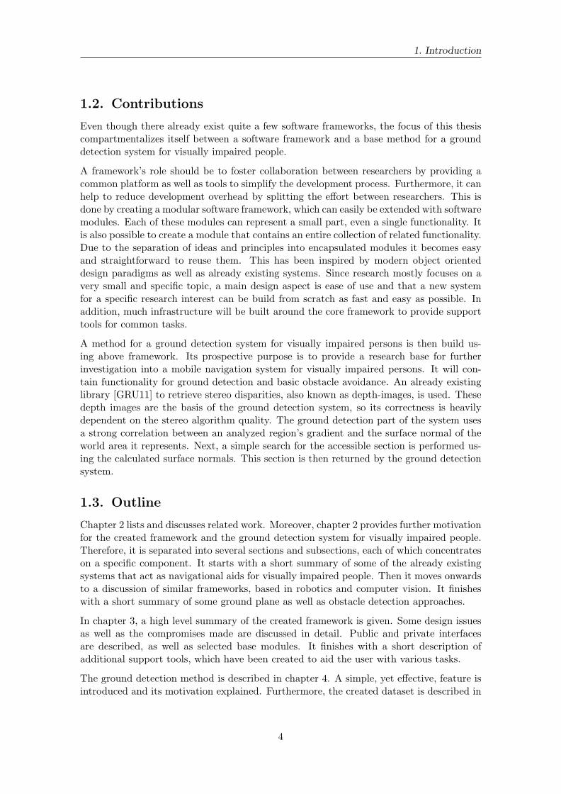
There have been attempts to replace the walking stick with digital means. The Guide-Cane [SUB03], as shown in figure 2.1, replaces the walking stick with a digitally enhancedcounterpart. It is similar to a normal cane, but has a two wheeled base and an array ofdistance sensors mounted to it. Obstacles in front of it, perceived close to the ground,are evaded. This is achieved by breaking the corresponding wheel, which generates anevasive maneuver by the person pushing it. The user is steered away from the obstaclein a circular motion until the obstacle is passed. In this regard, it acts similar to a guidedog. Another method uses sonar sensors and haptic feedback through small vibration unitssewn into the wearer’s garment and provides an unobtrusive and almost invisible way tosignal feedback [CTV05].
To achieve real-time capabilities, some systems rely on the existence of specific markers orreal world characteristics. This can be hard to do with a purely vision based approach dueto hardware restrictions imposed by the mobile platform. For example Coughlan and Man-duchi [CM09] rely on colored markers installed throughout a building that are detected bya mobile phone application to help location- and way-finding inside buildings. The idea isto improve location aware systems where the global positioning system (GPS) is not avail-able. Furthermore, this system can directly provide location and routing information tothe user. The main disadvantage of this system is that the markers must be provided and
7
2. Related Work
Figure 2.1.: The GuideCane housing and wheelbase. (Source: [SUB03])
the layout of a site must be known. Also, since its focus is clearly navigation, it does notconsider moving obstacles, such as people. It should therefore be seen as another comple-mentary aid to already existing techniques (such as the cane). The need for such markersis alleviated by Chen et al. [CFZ+12]. Here, an inertial measurement unit (IMU) is usedto sample the user’s kinematic data and thus its ego-motion. By combining informationabout walking direction, step length and frequency, a position estimation is created on ana priori known map.
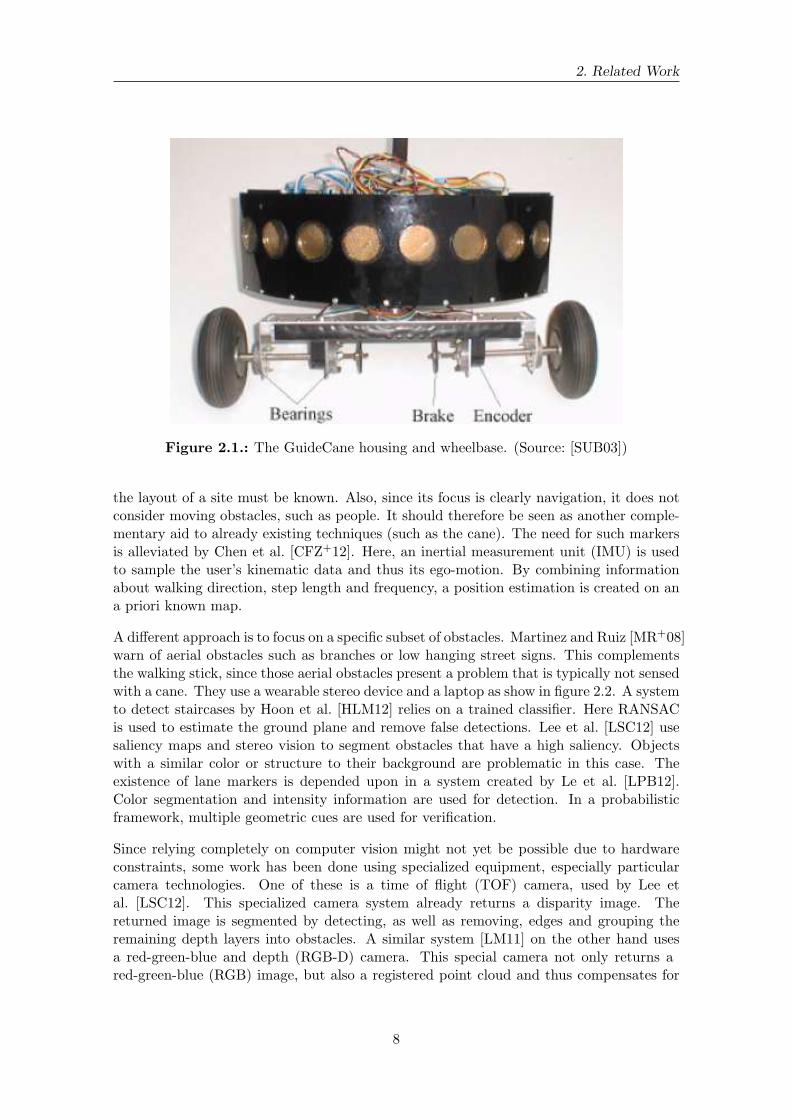
A different approach is to focus on a specific subset of obstacles. Martinez and Ruiz [MR+08]warn of aerial obstacles such as branches or low hanging street signs. This complementsthe walking stick, since those aerial obstacles present a problem that is typically not sensedwith a cane. They use a wearable stereo device and a laptop as show in figure 2.2. A systemto detect staircases by Hoon et al. [HLM12] relies on a trained classifier. Here RANSACis used to estimate the ground plane and remove false detections. Lee et al. [LSC12] usesaliency maps and stereo vision to segment obstacles that have a high saliency. Objectswith a similar color or structure to their background are problematic in this case. Theexistence of lane markers is depended upon in a system created by Le et al. [LPB12].Color segmentation and intensity information are used for detection. In a probabilisticframework, multiple geometric cues are used for verification.
Since relying completely on computer vision might not yet be possible due to hardwareconstraints, some work has been done using specialized equipment, especially particularcamera technologies. One of these is a time of flight (TOF) camera, used by Lee etal. [LSC12]. This specialized camera system already returns a disparity image. Thereturned image is segmented by detecting, as well as removing, edges and grouping theremaining depth layers into obstacles. A similar system [LM11] on the other hand usesa red-green-blue and depth (RGB-D) camera. This special camera not only returns ared-green-blue (RGB) image, but also a registered point cloud and thus compensates for
8
2.2. Frameworks
Figure 2.2.: A wearable stereo device for aerial obstacle detection. It is comprised of aBumblebee stereo camera and a laptop. (Source: [MR+08])
the costly depth map calculation.
2.2. Frameworks
As stated by Sullivan, Griswold and Hallen [SGCH01], ”. . .modularity in design createsvalue in the form of real options to improve a system by experimenting with new imple-mentations and substituting any superior ones that are found.” Such modularity cannotonly help to improve a system by replacing its parts, it also divides development effortsmore clearly among several developers, since it encourages a separation of responsibilities.To support modularity, a constantly growing number of frameworks have been developed,such as robot operating system (ROS) [QGC+09], Player 2.0 [CMG05], carnegie mellonnavigation toolkit (CARMEN) [MRT03] or the distributed wearable augmented realityframework (DWARF) [BBK+01].
2.2.1. Robotic Operating System
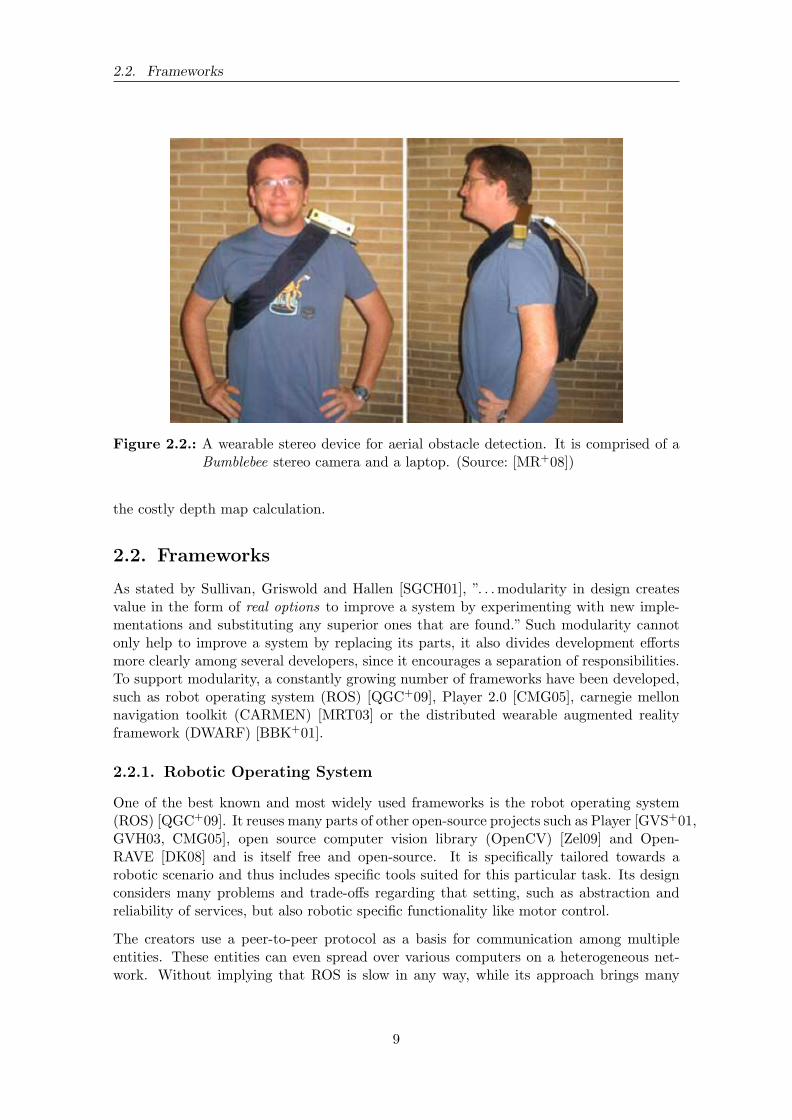
One of the best known and most widely used frameworks is the robot operating system(ROS) [QGC+09]. It reuses many parts of other open-source projects such as Player [GVS+01,GVH03, CMG05], open source computer vision library (OpenCV) [Zel09] and Open-RAVE [DK08] and is itself free and open-source. It is specifically tailored towards arobotic scenario and thus includes specific tools suited for this particular task. Its designconsiders many problems and trade-offs regarding that setting, such as abstraction andreliability of services, but also robotic specific functionality like motor control.
The creators use a peer-to-peer protocol as a basis for communication among multipleentities. These entities can even spread over various computers on a heterogeneous net-work. Without implying that ROS is slow in any way, while its approach brings many
9

2. Related Work
advantages, such as possible redundancy, fault tolerance and a distributed load, one canalso argue that it induces a fair amount of overhead. It might be more feasible to assemblemodular parts into a single execution unit and use multithreading to distribute work on asingle machine, while keeping tight control over all contained modules. This could be es-pecially useful when targeting a mobile platform, since mobile platforms tend to have lesscomputing power and resources available. Also when moving towards a mobile platform,multi machine capabilities are most likely to not be needed, so a compact integration todecrease latency and overhead should be preferable as there is only a single central pro-cessing unit (CPU) available and no distribution over the network required. Thereforea monolithic design should be favored, as it reduces the overhead from communicationamong entities. To be extensible while still being monolithic, a functional and objectoriented approach can be used, where each module is controlled by a master authority.
While at first a framework that has similar goals to ROS will likely seem redundant, thedifferences in design choices made during implementation of these ideas might largely onlybe perceived upon intense usage of said systems. The plethora of available tools, optionsand settings of ROS can be intimidating and represents an unwanted barrier to entry, soa smaller framework more suited towards a particular goal can greatly improve learningspeed. This is especially true when for example an assignment is given to lab students. Insuch a scenario, using a framework is desired in order to increase productivity by reusingalready available components. Furthermore, collaboration among individual groups ispromoted through the use of a common base. One of the main goals of the createdframework is thus ease of use, especially for students that do not have prior experiencewith computer vision systems and programming. Using a fully featured framework likeROS can be more of a hindrance under such specific circumstances.
2.2.2. Player 2.0
Player 2.0 [CMG05] is a widely adopted framework for robotic scenarios. It is an ad-vancement of Player [GVS+01, GVH03], which uses transmission control protocol (TCP)sockets to create a server/client architecture. Besides sockets, Player 2.0 is also usinginter-process communication (IPC) as a means to connect various software modules andlibraries with one another.
Being a robotic framework, Player contains, just like ROS 2.2.1, many parts to controlrobot actuators and get information from its sensors. While different kinds of sensors areoften used in a computer vision oriented framework, several capabilities are not needed inthat case, like motor control. Although this server client module brings much flexibility, italso creates communication overhead that is best avoided when being on a limited platform.
2.2.3. Distributed Augmented Reality Framework
The distributed wearable augmented reality framework (DWARF) [BBK+01] is anothersystem. Figure 2.3 shows an indoor scenario with a superimposed map of a building. It is aframework built to simplify the developing process of augmented reality (AR) applications.Similar to the augmented reality toolkit (ARToolKit) [Kat02] library, DWARF containsa component to deal with low level hardware issues, such as trackers. Furthermore, theDWARF framework concentrates on providing a complete world model, a task flow engine
10
2.3. Ground Plane and Obstacle Detection
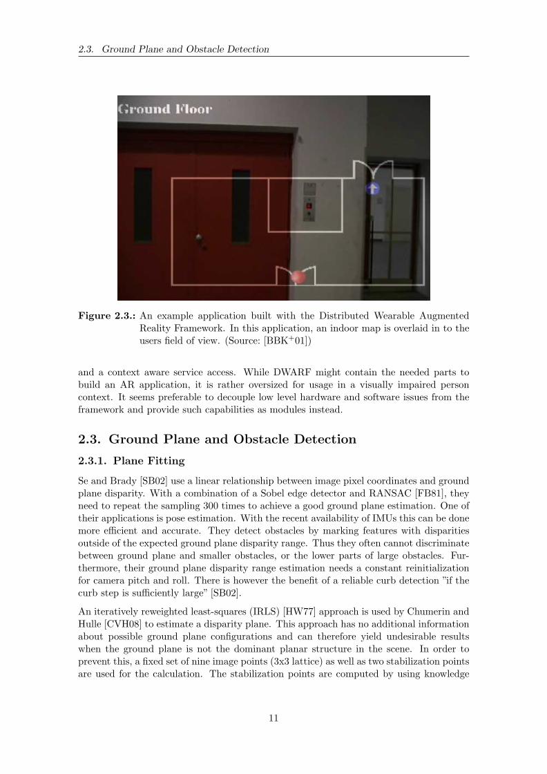
Figure 2.3.: An example application built with the Distributed Wearable AugmentedReality Framework. In this application, an indoor map is overlaid in to theusers field of view. (Source: [BBK+01])
and a context aware service access. While DWARF might contain the needed parts tobuild an AR application, it is rather oversized for usage in a visually impaired personcontext. It seems preferable to decouple low level hardware and software issues from theframework and provide such capabilities as modules instead.
2.3. Ground Plane and Obstacle Detection
2.3.1. Plane Fitting
Se and Brady [SB02] use a linear relationship between image pixel coordinates and groundplane disparity. With a combination of a Sobel edge detector and RANSAC [FB81], theyneed to repeat the sampling 300 times to achieve a good ground plane estimation. One oftheir applications is pose estimation. With the recent availability of IMUs this can be donemore efficient and accurate. They detect obstacles by marking features with disparitiesoutside of the expected ground plane disparity range. Thus they often cannot discriminatebetween ground plane and smaller obstacles, or the lower parts of large obstacles. Fur-thermore, their ground plane disparity range estimation needs a constant reinitializationfor camera pitch and roll. There is however the benefit of a reliable curb detection ”if thecurb step is sufficiently large” [SB02].
An iteratively reweighted least-squares (IRLS) [HW77] approach is used by Chumerin andHulle [CVH08] to estimate a disparity plane. This approach has no additional informationabout possible ground plane configurations and can therefore yield undesirable resultswhen the ground plane is not the dominant planar structure in the scene. In order toprevent this, a fixed set of nine image points (3x3 lattice) as well as two stabilization pointsare used for the calculation. The stabilization points are computed by using knowledge
11
2. Related Work
(i) (ii)
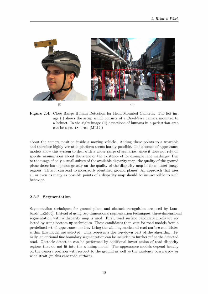
Figure 2.4.: Close Range Human Detection for Head Mounted Cameras. The left im-age (i) shows the setup which consists of a Bumblebee camera mounted toa helmet. In the right image (ii) detections of humans in a pedestrian areacan be seen. (Source: [ML12])
about the camera position inside a moving vehicle. Adding these points to a wearableand therefore highly versatile platform seems hardly possible. The absence of appearancemodels allow this system to deal with a wider range of scenarios, since it does not rely onspecific assumptions about the scene or the existence of for example lane markings. Dueto the usage of only a small subset of the available disparity map, the quality of the groundplane detection depends greatly on the quality of the disparity map in these exact imageregions. Thus it can lead to incorrectly identified ground planes. An approach that usesall or even as many as possible points of a disparity map should be insusceptible to suchbehavior.
2.3.2. Segmentation
Segmentation techniques for ground plane and obstacle recognition are used by Lom-bardi [LZM05]. Instead of using two-dimensional segmentation techniques, three-dimensionalsegmentation with a disparity map is used. First, road surface candidate pixels are se-lected by using bottom-up techniques. These candidates then vote for road models from apredefined set of appearance models. Using the winning model, all road surface candidateswithin this model are selected. This represents the top-down part of the algorithm. Fi-nally, an optional fine boundary segmentation can be included to further refine the detectedroad. Obstacle detection can be performed by additional investigation of road disparityregions that do not fit into the winning model. The appearance models depend heavilyon the camera position with respect to the ground as well as the existence of a narrow orwide strait (in this case road surface).
12
2.3. Ground Plane and Obstacle Detection
2.3.3. Obstacles
While most of the works from section 2.3 already use a correlation between the presenceof ground plane and obstacles, there also exists an array of work focusing on obstacledetection. Many of those deal with automobile settings [LAT02, BPCL06]. They usevarying techniques, such as the Hough Transformation [DH72], to detect prominent orsalient objects as well as optical flow [HS81].
A quite different approach is used in an obstacle avoidance system for a rotorcraft un-manned aerial vehicle (UAV) [Hra08]. Through the use of special equipment, such asstereo on chip (STOC) technology and an embedded computer, real-time capabilities areachieved. A sophisticated framework for probabilistic map occupancy is then used to gen-erate a point cloud representing the surrounding obstacles. This technique is limited by”the amount of memory (such a map) can require” [Hra08], since it becomes very big forrather small voxel resolutions. Furthermore, a probabilistic roadmap planning as well as astereo-based replanning is calculated using techniques such as A* or, more efficiently, D*Lite.
A great many works deal with pedestrian detection in urban settings, some even on awearable platform [ML12]. Here, depth information is gathered through the use of aBumblebee camera, which is attached to a helmet as shown in figure 2.4 (i). Then depthtemplates of upper bodies are learned and matched to the disparity image. This worksreally well, even for crowded scenes as can be seen in figure 2.4 (ii). In a similar systemstereo camera rigs mounted on wheeled vehicles are used [ELSVG09, ESLVG10]. Thisresults in a rather steady camera movement with only very few pitch and roll changes. Herea probabilistic model is used through a Bayesian network, which models the dependency ofperson detection, detection size and location, and by using all detections creates a commonground plane estimation. This model is then updated in each frame, so it can deal withstatic as well as moving obstacles.
13


3. The Blind and Visually Impaired
Support System
Client BVS ModuleControl
Loader
Logsystem
Config
Logger
Connector
Figure 3.1.: An overview of the blind and visually impaired support system (BVS) frame-work. Additional system parts are shown in appendix A.
This chapter gives an overview of the created framework presented in this thesis. Its mainparts, public and private interfaces, are discussed and some design decisions are explained.Then, the modules created to aid in computer vision tasks are presented in detail.
3.1. Main Design Goals
The blind and visually impaired support system (BVS) has been created to simplify col-laborative research efforts towards visually impaired users. It was designed to be fast tolearn and as easy to use as possible with a setup time of less than a few hours. In order tonot impose special demands onto the user, the framework itself is completely free of anyspecial purpose parts created towards a particular research domain. Such functionality is
15
3. The Blind and Visually Impaired Support System
outsourced into modules, so for every use case the decision to include these can be madeupon the specific needs and requirements of a project. Thus the framework itself is keptas abstract as possible.
One of the reasons to create this framework is to encourage code reuse instead of codeduplication. Often, specific code is written to deal with a certain library, driver or dataconversion. This code is often hard to separate from other aspects of an application sinceit will most likely be deeply interwoven with other application parts. Therefore, reuse ismade much harder than it would be in a strictly separated environment. Also, bug fixingefforts must be duplicated, because a bug found in one application does not translate wellinto another application using parts of the same code base. To counter this development,it has long been proposed and successfully deployed to group functionality into classes,objects or functions. The notion of modularity represents nothing different, but goes astep further. With separate objects or classes, there are no specifications about commondata structures or caller formats. On the contrary, within a modular approach, policiesand procedures to share and use data are fundamental attributes. Every module part ofa larger system has to obey these rules. Thus modularity presents a stronger argumenttowards reusability, connectivity and interchangeability.
To reduce overhead created by the modular framework, a functional approach has beentaken. Each module consists of an object with a core functionality. This functionalityrepresents its main contribution, while the rest of the module deals with startup andshutdown of the module, for example initializing and shutting down hardware systems.Oftentimes, additional information or functionality is necessary and must be providedoutside the core functionality. By separating support and core functionality, the conceptof a pure function is approached. Modules can be connected, just like functionality wouldbe chained, in a program to request a certain outcome. Using the framework, this can bedone dynamically. The framework will call their core functionality in the order they havebeen specified, while all the side effects of data passing and data conversion have alreadybeen taken care of. The inflicted overhead of the framework can be made negligible byusing a flat calling hierarchy. Eventually, the framework approximates the running costs ofa specifically created application which simply calls several functions, but with the addedadvantage of being dynamically changeable, even at runtime.
The framework itself is completely encapsulated inside a library object, also known as”shared objects” or ”dynamic link libraries” [BWC01]. While this contradicts the commonnotion that a library is not a framework, it allows for the creation of a two sided interface,one for clients that desire to control the framework, the other one for framework modules.Both interfaces provide the specific parts needed and are described in the following sections.Since the framework allows for easy creation of additional clients, it is a straightforwardprocess to include this framework into others.
Documentation is an important step towards creating an easy to use framework. Thus,the popular Doxygen [vH08] documentation system is used throughout the framework andits modules. This allows for a comfortable generation of the documentation as well as theability to supply pre-generated documentation bundled with the framework library.
The, at the time of this writing, new C++11 standard is used extensively throughout theframework. It greatly helps with programming several aspects of the framework, especially
16
3.2. Public Interfaces
multi threading. Although the multi threading support in C++11 is far from complete, itsupports system portability as well as code simplicity. As a build system, cross-platformmake (CMake) [MH08] is used to simplify the build process of the framework and its mod-ules. It allows for an easy to use and understandable build structure. Furthermore, eachmodule can be bundled with its own compiling directives, which separates the process fromthe framework as well as other modules. Thus, it alleviates the treatment of dependencies,even inter-module dependencies. To manage the framework’s source code as well as thesource code of created modules, git [TH05] is used. It allows for a distributed version con-trol and is used widely in the industry as well as the open source software scene, amongstothers the Linux kernel development. Moreover, git has become another important toolto promote the sharing of resources with other researchers or research students.
3.2. Public Interfaces
3.2.1. Client Interface
The client interface provides the basic functionality for the entire BVS framework. It allowsfor a dynamic change of all existing framework traits at startup as well as any time duringusage. Such traits are for example a logging system, which will be described in detail aspart of the module interface in section 3.2.2. Furthermore, multi-threading and modulepooling can be enabled or disabled. The major reason to allow explicitly the removalof multi-threading is debugging. In a debugging scenario, it is often preferable to haveall modules running inside a single thread, since not all debugger handle multi-threadedscenarios rather well. Also, it allows the debugging process to concentrate on issues thatare not related to the nature of simultaneous execution in multi-threaded scenarios. Assuch, it cannot help with issues that stem from multi-threaded synchronization issues.
A framework client can, after the creation of a framework instance, load modules indi-vidually or use the supplied configuration mechanism (section 3.2.4) to load a predefinednumber of modules as well as framework settings. This mechanism allows for a fast cre-ation of systems that can be loaded simply by specifying a configuration file to the client.Furthermore, it is easy to create for example demo applications using this technique. Anadded advantage in such a scenario is that while the number as well as the order of compo-nents are fixed, individual components benefit from bug fixing and feature improvements.
Of course, the client interface contains methods for the client to start, run, step, pause andquit the frameworks operation. A step, also referred to as a round, is considered to be asingle execution of all loaded modules. All modules are run synchronized by the framework,executed in the order they are specified or running in parallel in a highly multi-threadedscenario. Synchronization is achieved by using a barrier, a synchronization method thatregulates concurrency among a fixed number of threads by enforcing rendezvous points.So during each round, it is guaranteed that each module of a system will run exactly once.
An asynchronous control mechanism has been considered, but it was found that it ispreferable to leave unused processing power to busy modules, instead of having all modulesconstantly poll, therefore actively competing for resources, and thus occupying all availableCPU cores. The major drawback of having all modules run in a synchronized fashion isoverall round time as well as system delay. The overall round time is the time that it
17
3. The Blind and Visually Impaired Support System
takes for all modules to finish one round. The system delay, however, is the accumulatedtime it takes for information to pass through the entire system, that is the entire chainof modules from the first to the last one. Thus one slow module, most likely processor orinput/output dependent, can dramatically increase the round time and thereby the overallsystem delay. In order to alleviate the effects of such a behavior, statistics such as thecollection of individual module and pool runtimes during each round have been integratedinto the framework to detect such ill manners. A module pooling mechanism has beenintegrated to join the execution of other modules into single threads, thus decreasing theoverall round time, see section 3.3.2. Since this mechanism enables multiple modules to beexecuted using current round information from their predecessors, the system delay canbe reduced by several round times, depending on how many modules can be bundled intosuch a pool.
Given that all modules belong to the same system process, unlike with ROS, passingdata between modules has been implemented by using shared memory instead of messagepassing or IPC. This guarantees a low overhead, as connections must only be establishedonce and is especially advantageous for large amounts of data, such as images. Moreinformation about this mechanism can be found in the section about module connectors,section 3.2.3.
The framework has been designed to make heavy use of the Pimpl Idiom [Sut09] whereverpossible, which is also known as a ”compilation firewall.” Its purpose is to hide the specificsof an implementation behind a public interface. This allows programmers to change theinner workings of a system, without exposing these changes to the outside world. Anysystem depending on the framework does not need to be recompiled upon frameworkimplementation changes, since those are not reflected in the public interface. Therefore,the usage of the Pimpl Idiom allows for later internal changes of the framework withoutaffecting already used instances.
As stated above in section 3.1, the purpose of having this client interface is the ability toencapsulate the framework into a library object. This allows for greater portability as wellas easier integration within other systems. However, this leads to a minor problem, whichis that a framework that needs to be controlled by a client cannot run on itself. That iswhy a daemon is provided with the framework. It is presented in the next section.
Daemon
A daemon has been created that serves two purposes. First, it can control the frameworkin headless environments, meaning it runs on the command line. Second, it serves as anexample of how to use the client interface. Future work is planned for a graphical client,which should also serve as a debugging tool.
The daemon starts an interactive shell through which the user interacts with the frame-work. In addition, this shell can be used to output the systems log. These are notframework features, but belong to the daemon implementation. Giving the user interac-tive control to the framework is perhaps the most important aspect of the developmentprocess. Only through this access modules can easily be interchanged at runtime. Aframework client or daemon could also be written to simply run a specific system, whichcould be created through the use of the configuration mechanism, or implemented insidethe daemon’s source code.
18
3.2. Public Interfaces
Furthermore, the daemon allows to overwrite any kind of configuration option on thecommand line. This permits the usage of the daemon inside a fully scripted scenario,where any property of the system can be changed upon each execution of the framework.Especially for system and algorithm optimization this represents an invaluable tool.
3.2.2. Module Interface
The second interface is aimed towards the integration of framework modules, it must beconformed to in order to allow the framework proper integration. To promote a con-sistent module interface, a helper tool has been created that creates an empty templatefor the newly created module. This frame can then be extended to include the desiredfunctionality.
Such an approach allows for easy, partly automated and, therefore, fast creation of librarywrappers. These wrappers are completely self-contained, they only define their desiredinput channels and provided output channels as well. Once the library functionality hasbeen added to the module, this library can then be reused in many different projects.Instead of having custom written code each time an external library is used, this processabstracts the library and wraps it into an easily reusable container.
While modules are controlled completely by the framework, they are still allowed to makefull use of all system resources, for example starting additional threads. Such behaviorshould always be considered carefully, since especially in high speed scenarios the additionaloverhead caused through the additional synchronization layer is not negligible.
There is however one important ability for modules: they can request a system shutdownif required. This can happen when for example an input module has no more data toprocess or when faulty states are detected inside a module. The framework will then notimmediately shut itself down, but rather keep the system running for a while to give allother modules that belong to an active system a chance to finish processing their inputand properly shutdown for example hardware components. Additionally, modules caninform the framework of various module states. One such state could be that a moduleis repeatedly not receiving any input. While the framework itself cannot handle suchsituations yet, a client could, in an interactive setting, act upon it.
Sometimes it is needed to store various configurations of an algorithm, which is itselfrepresented as part of the framework through a module. The configuration subsystem,described in section 3.2.4, allows to store these settings inside a more dynamic environment.They can be bundled into module configurations, which can then easily be accessed throughthe frameworks module configuration syntax, shown in section 3.2.4. This allows for a fastswitch between several already created module configurations.
3.2.3. Module Connectors
Module connectors define the way for a module to acquire input from other modules aswell as send output to others. The connector system has been built to allow for a highspeed message exchange with negligible overhead. Such connections are initialized bythe framework upon startup. Afterwards, a sending entity can put its data into a sharedmemory region. This region is automatically announced to the receiving entity. To prevent
19
3. The Blind and Visually Impaired Support System
concurrent access, a locking mechanism is included. This ensures the integrity of data inmulti threaded scenarios by excluding race conditions and other synchronization issues.
The framework has been built to be completely agnostic to the type of passed data insidesuch connectors. To it, all passed data are just memory regions. The main reason forthis design decision is to keep the framework free from application specific code. Thishowever, has the disadvantage that each module must check the validity of its input beforeprocessing it further to avoid crashes resulting from incomplete or corrupted data, whichis widely considered a good behavior anyway. On the software side, through the use ofmetaprogramming, a connector is type safe, feels and handles just like a native object, soit is easy to use.
In order to provide at least a bit of support with type checking, the framework can relyon run-time type information (RTTI) to detect incorrectly setup connectors during thestartup phase. This can be explicitly disabled if desired, since not all compilers might beable to include such information in the resulting binary. The produced overhead of thismechanism is negligible, as it only affects the startup time.
3.2.4. Configuration Subsystem
The configuration subsystem, named simply Config, serves an important purpose whiledeveloping a system. It allows for an easy change of system settings and configurations.With the configuration mechanism, the user can create or change all system aspects,without having to recompile. Furthermore, having a configuration that can be savedand passed around to other researchers enables easy sharing of system implementations,instantiation, algorithm parametrization and their results.
As with any configuration mechanism, it demands a specific syntax to be followed. Thissyntax has been kept simple, while still allowing for advanced features, such as arrayspecifications inside a single line, as shown in figure 3.2. As can be seen in the example,through the use of metaprogramming, the configuration system converts desired optionvalues into the demanded formats. Thanks to this mechanism, the user does not have totake care of any form of configuration parameter conversion. This mechanism can even beextended to user created types.
In order to separate module configurations from the base framework settings, a sourcingmechanism has also been included. This allows to distribute a module’s configurationbundled with the module code, while still enabling an easy integration into an existingsystem by simply sourcing its configuration options.
Module Configuration Syntax
To support modules that assemble a broader array of functionality or support differentmodus operandi, a special module syntax is used by the framework as shown in figure 3.3.This syntax helps in the definition of modules using various of its possible capabilitiesby allowing to select a module with a certain configuration. Furthermore, by decouplingthe name or identification of a module from its origin, the underlying implementationof a module instance can easily be switched by another implementation without causingfurther problems down the module graph, especially when connecting the module to other
20

3.2. Public Interfaces
# eve ry t h in g a f t e r ’#’ i s cons idered a commentopt ion = ignored # must be long to a s e c t i on
# s e c t i o n s and op t i ons are case i n s e n s i t i v e[ s e c t i o n ] # same as [ SeCtIoN ]opt ion1 = value1 # commentOption1 = value1 # warning , r e d e f i n i t i o n
# spaces are s t r i p p e d i f not i n s i d e quo tesopt ion2 = ”value2 with spaces ” # s i n g l e quo tes a l s o p o s s i b l eopt ion3=valueopt ion4 = valueopt ion5 =value
# a l l o f the above are v a l i d e n t r i e s
booleanOption = true# for boo lean type option−va lue pa i r s :# ’1 ’ , ’ true ’ , ’True ’ , ’TRUE’ ,# ’on ’ , ’On’ , ’ON’ ,# ’ yes ’ , ’Yes ’ or ’YES’# are i n t e r p r e t e d as TRUE, ev e r y t h in g e l s e as FALSE
s t r i n gL i s t = elementOne , ”element Two” , ’ e lement Three ’boo l eanL i s t = true , f a l s e , True# accessed by us ing getValue wi th s t d : : vec tor<TYPE>
# the p lus−equa l opera tor can be used to expand e x i s t i n g op t i ons# t h i s turns them in to a l i s t , a l l ow ing f o r f a s t e r r eorder ingl i s t = onel i s t += twol i s t += three#l i s t += fourl i s t += f i v e# the r e s u l t o f t h i s w i l l be : l i s t = one , two , three , f i v e
# other con f i g f i l e s can be sourced ( inc luded )source OtherConf igFi l e . txt
Figure 3.2.: Configuration subsystem syntax.
21

3. The Blind and Visually Impaired Support System
# modules [+]= [+ | poolName ] id [ ( l i b r a r y [ . c on f i g ] ) ] [ . connec t ions ]## [+] −> Append to the module l i s t .# [+ | poolName ] −> Load module i n s i d e i t s own poo l ( ’+ ’) or# add/ cr ea t e to a module poo l o f name ’ poolName ’# which a l s o runs i n s i d e i t s own thread and execu t e s# added modules in the g iven order .# NOTE: ’+ ’ i s e f f e c t i v e l y a shorthand f o r ’ [ i d ] id ’ .# NOTE: ’ poolName ’ MUST be i n s i d e ’ [ . . . ] ’ , ’+ ’ not .# [ ( l i b r a r y . . . ) ] −> Use as module l i b r a r y to a c t u a l l y load# module from , u s e f u l f o r mu l t i p l e modules from a# s i n g l e l i b r a r y .# [ . c on f i g ] −> Use t h i s c on f i g u r a t i on f o r the module , u s e f u l so# the module name does not change but i t s# con f i g u ra t i on can be changed e a s i l y .# [ . connec t ions ] −> Options f o r connectors , l o o k s as f o l l o w s :# input ( t e s t . output ) [ . input2 ( t e s t . output2 ) ] . . .## I f c on f i g u r a t i on and/or l i b r a r y are not given , the system w i l l# use the g iven id in s t ead ( u s e f u l as a shorthand ) .## Examples :# < SHORTHAND > < VERBOSE ># id id ( id . i d )# id ( l i b ) id ( l i b . i d )# +id2 ( l i b 2 ) [ id2 ] id2 ( l i b 2 . id2 )# +id3 ( l i b 2 . conf ) . in ( id2 . out ) [ id3 ] id3 ( l i b 2 . conf ) . in ( id2 . out )# [ poo l ] id4 . in ( id3 . out ) [ poo l ] id4 ( id4 . id4 ) . in ( id3 . out )
Figure 3.3.: Module configuration syntax.
modules. Without this mechanism, all appearances of the original module identificationwould have to be changed as well if an implementation was switched. An example of howto use the module configuration syntax to create and connect various modules is shown infigure 4.1.
3.2.5. Logging Subsystem
Having the ability to output any data at any given point during a programs executiontime can be a major factor in diagnosing problems early on. As such, a logging systemshould be powerful and easy to use but still lightweight.
In order to simplify the logging mechanism for an user, a logger instance is created, which isthen used to interact with the logging backend. This object contains all the users settingsfor its logger instance, such as the instance’s name and verbosity level. Furthermore, itcan be selected, whether the instance should log to a console only or also to a file. The
22
3.3. Private Interfaces
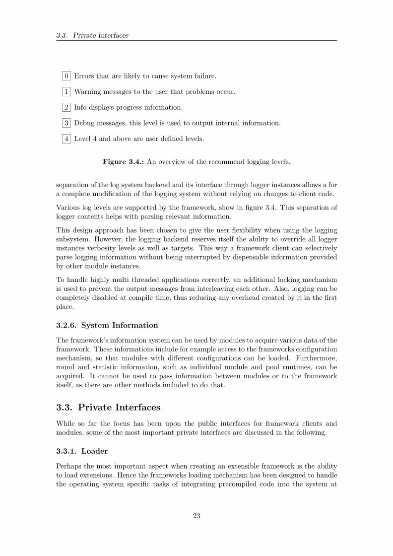
0 Errors that are likely to cause system failure.
1 Warning messages to the user that problems occur.
2 Info displays progress information.
3 Debug messages, this level is used to output internal information.
4 Level 4 and above are user defined levels.
Figure 3.4.: An overview of the recommend logging levels.
separation of the log system backend and its interface through logger instances allows a fora complete modification of the logging system without relying on changes to client code.
Various log levels are supported by the framework, show in figure 3.4. This separation oflogger contents helps with parsing relevant information.
This design approach has been chosen to give the user flexibility when using the loggingsubsystem. However, the logging backend reserves itself the ability to override all loggerinstances verbosity levels as well as targets. This way a framework client can selectivelyparse logging information without being interrupted by dispensable information providedby other module instances.
To handle highly multi threaded applications correctly, an additional locking mechanismis used to prevent the output messages from interleaving each other. Also, logging can becompletely disabled at compile time, thus reducing any overhead created by it in the firstplace.
3.2.6. System Information
The framework’s information system can be used by modules to acquire various data of theframework. These informations include for example access to the frameworks configurationmechanism, so that modules with different configurations can be loaded. Furthermore,round and statistic information, such as individual module and pool runtimes, can beacquired. It cannot be used to pass information between modules or to the frameworkitself, as there are other methods included to do that.
3.3. Private Interfaces
While so far the focus has been upon the public interfaces for framework clients andmodules, some of the most important private interfaces are discussed in the following.
3.3.1. Loader
Perhaps the most important aspect when creating an extensible framework is the abilityto load extensions. Hence the frameworks loading mechanism has been designed to handlethe operating system specific tasks of integrating precompiled code into the system at
23
3. The Blind and Visually Impaired Support System
runtime. The loader abstracts the rather arcane operating system functions to handledynamic libraries into an easy to use interface. It handles the loading of dynamic libraryobjects, the creation of module instances from these and it registers the modules withinthe framework. Of course, it also does the opposite operations when closing a module thatis no longer needed. While the integration of modules seems trivial, it strongly dependsupon the used language and its implementation. At the time of writing, C++ did nothave any form of module support. That is why the frameworks relies on old C interfacesto achieve the same functionality since these are platform specific. Concentrating thisfunctionality into a single place decreases the overhead needed when porting to a differentplatform is desired.
Working with a modular system can bring a lot of benefits, such as the ability to reload amodule because it is either misbehaving, has been corrupted or there is a newer version ofit available. The latter happens especially often during the development cycle of a system.When reloading a module through traditional means, it loses all internal state information,unless these were saved inside an external structure beforehand and, therefore, supportedby the module. In order to support a true module reloading experience, a hot swappingcapability has been added to the loading mechanism.
Module Hot Swapping
To substantially decrease the time of a development cycle, a hot swapping mechanismhas been included in the framework. Instead of relying on a module to lose all its internalstate or save said state in an external structure, the occupied memory of a module instanceis reused when recreating the updated module instance. While this technique is neitherdesirable nor standard conform, it has proven itself to be reliable. Instead of deleting amodule and thus erasing all of its memory, the module instance is kept in memory whilethe old library version is unloaded. Then, a newer version of the library is loaded into thesystem and combined with the old instance’s memory. However, this can lead to all sortsof problems and crashes and should therefore only be used inside a development scenario.Even then, it has its limitations due to the way objects are laid out in memory. Exceptfor a hot swapping mechanism that requires special support, there is nothing that can bedone to prevent it. Such an operating procedure is even considered ”undefined behavior”by the C++ standard [Str93] and should thus be used with caution.
Although the inherent insecurity of this mechanism cannot be eliminated, it has provenitself really valuable in various development situations. Especially when relying on hard-ware that has a long warm up and cool down phase - for example some camera systems -this reduces the iteration cycle by a fair amount of time.
3.3.2. Control
The next important part of a framework is the ability to gain full control over all modules.In the BVS framework this is implemented in the control system.
The control system supports a messaging mechanism. It can be started as a separatecontrol process, which runs inside its own thread. That way, a client could offer an in-teractive shell that connects to the control system and signals the desired actions to thecontrol system. Furthermore, the control system can be used directly by a client through
24
3.4. Base Modules
the public interface, but this has the disadvantage that every round needs to be triggeredmanually.
A round is considered a full cycle, that is an execution of all involved modules from startto finish. The round time is limited by the slowest module since all modules run in asynchronized mode. The reason for this is mainly to not lose any data due to overzealousmodules and to free processing capabilities.
A barrier is used to synchronize the individual modules. Such a barrier is a well knownthread synchronization primitive used in many operating systems. C++ does so far notinclude a barrier mechanism, while it has gained a lot of support for multi threading inits latest incarnation C++11. Furthermore, most barrier implementations only considera static barrier, where the number of participants never changes. Since the frameworksintended use case requires it to be as dynamic as possible, such a static barrier cannotbe used in this context. Thus a custom barrier had to be written that allows for a dy-namic adjustment of the participating parties, in this case module pool threads. The poolabstraction is explained in the following section.
Pools
Pools are an abstraction mechanism of the framework to simplify dealing with individualmodules or module groups. A module pool consists of at least one or more modules. Ifa pool does not contain any more modules, it takes care of its own proper destruction.Modules can be added or removed from a pool dynamically, i.e., during runtime, withoutaffecting other modules, except when disintegrating parts of their input sources.
The major reason to introduce module pools is the ability to group small and fast modulestogether. As explained in section 3.2.1, this can significantly reduce the overall systemdelay when a single module has a large execution time. Thus a higher throughput canbe achieved, which equals a higher frame rate. While at first, there were different controlstructures depending on whether a module was to be run in parallel or not, module poolsgreatly simplified the underlying architecture.
3.4. Base Modules
The base framework itself contains no specific low level drivers. To support developmentof systems aimed towards visually impaired people, some needed functionality has beenencapsulated inside basic modules. These modules are provided in combination with theframework and can thus, while they are technically not required to run it, be considereda part of it. They also serve the purpose of being exemplary to the creation of furthermodules.
3.4.1. Capture Module
The capture module has been created to simplify the process of retrieving input fromone camera or if necessary camera arrays. This is a fundamental step in computer visionapplications. OpenCV [Zel09] is relied upon to deal with hardware issues, such as drivingdifferent camera gear and retrieving images over various connection types. The number ofdesired cameras, also referred to as nodes, can be set upon startup in a configuration file.
25
3. The Blind and Visually Impaired Support System
During usage of the framework it became apparent there would be a need to store captureddata and retrieve it later on. Thus, the capture module has been extended. It can storeindividual frames as images or videos as well as retrieve recorded data from these. Thisallows for a complete replay of recorded data. Such a mechanism can be used for exampleto evaluate algorithms or a dataset.
3.4.2. Calibration Module
When working with a stereo camera system, calibration is an important step and thismodule has been conceived as a result. It is designed in such ways that it supportsintrinsic calibration of multiple cameras as well as extrinsic calibration of stereo camerasystems, while it could also be extended to calibrate an entire array of cameras. It servesas an abstraction layer to the OpenCV [Zel09] calibration methods. It connects to thecapture module to do a live calibration but it can also calibrate a camera from alreadysaved image series.
To support live calibration, an auto shot mode is integrated into the module. In this modethe calibration module waits until the calibration pattern can be reliably detected in allcameras. Then snapshots are taken which are in return used later for further processing.In order to increase the calibration quality, which is an important step in retrieving goodresults from stereo algorithms, a calibration guide has been designed. This optional guidetries to ensure that pattern detections are evenly spread all over the image in such a waythat the calibration process does not overfit towards a particular region of the image, whileneglecting others.
After a successful calibration, the results can be extracted from a calibration file for furtheruse and the input images can be extracted from the calibration module in a rectifiedcondition. Also, after a successful calibration, the results will automatically be reusedduring the following executions.
3.4.3. Stereo Vision Module
To test the speed and reliability of a few stereo algorithms, a separate module has beencreated. This module uses the graphics processing unit (GPU) and OpenCV [Zel09] tospeedup the stereo reconstruction process. It can dynamically switch between a blockmatching algorithm, a belief propagation and a constant space belief propagation. Themodule was used in early stages to test the correctness of the capture system, especiallythe calibration module.
3.5. Additional Tools
To simplify framework usage, some additional tools have been included. When an userfirst downloads the framework, a setup function can be run. This will install the desiredmodules that are already known to the framework, but this process can also be expandedto include repositories of other origins.
Furthermore, an update function is provided. Since the framework supports modules fromvarying sources, it can become quite cumbersome to retrieve updates from a lot of differentrepositories and keep all in sync. That is why the update function will look for installed
26

3.5. Additional Tools
repositories and update these accordingly. This can even be done without losing localinformation. Sometimes it might be necessary to do the opposite of a framework update,a version rollback. For this case, there also exists a helper function.
Also, to ensure module consistency, a module creation script is included. This has alreadybeen described to some detail in section 3.2.2. All of the above capabilities are integratedinto the main utility script located in the base of the repository.
27


4. The Ground Detection System
After creating the framework a ground detection mechanism has been developed. Sec-tion 4.1 discusses the design decisions, some of its components and the underlying al-gorithm. An introduction into the created dataset comes afterwards in section 4.2. Insection 4.3 follows a description of the experimental setup as well as the used measure-ments. Finally, the results are presented in section 4.4.
4.1. Design
The ground detection system is built using the created framework that is described inchapter 3. Moreover the supplied modules detailed in section 3.4 are used. These basemodules are used to reduce the effort of building a functional prototype as well as to testtheir functionality. Furthermore they provide much of the needed capabilities, such asinput and output of video or image data and calibration of the used stereo camera system.
Since the entire framework is built upon the assumption of a modular system, the actualground detection algorithm is encapsulated inside a module. This way it can be easilyused with the created framework and reuse in different applications or usage scenarios isgreatly simplified. Encapsulation of the ground detection system furthermore enables theuse of sophisticated framework support tools. For example the hot swapping mechanismdescribed in section 3.3.1 helped to reduce the development time of the algorithm by a fairamount. Due to the modular nature of the framework, changing the input to the grounddetection module is quite simple.
In the following sections, a few parts of the ground detection system will be further ex-plained. This starts with a general system overview. Afterwards, a short description ofthe used stereo reconstruction algorithm follows. It is followed by an explanation of thealgorithm and its main feature, the gradient detection.
4.1.1. System Description
The ground detection system consists of various components, such as the base modules de-scribed in section 3.4 and the actual ground detection. Furthermore an additional stereo re-
29

4. The Ground Detection System
### INPUTmodules = cap (CaptureCV . video )
### PROCESSINGmodules += ca l i b ( CalibrationCV ) . in1 ( cap . out1 ) . in2 ( cap . out2 )modules += e l a s ( StereoELAS ) . inL ( c a l i b . out1 ) . inR ( c a l i b . out2 )modules += ground ( GroundDetector . GroundDetector ) . in ( e l a s . outL )
### OUTPUTmodules += vid (CaptureCV . v i d e o wr i t e r ) . in1 ( ground . out1 )
Figure 4.1.: A framework configuration example. Here, a video is being processed andthe calculated ground plane information is saved into another video file.This example shows the convenience of a modular framework. With a fewconfiguration lines, a complex system can be realized. It should be notedthat in this example multi threading is not used, but doing so requires onlya simple operation, adding a ’+’ in front of each module instantiation.
construction module has been created to encapsulate the efficient large-scale stereo match-ing (ELAS) stereo library that yields better results than the OpenCV implementations.
The capture module, discussed in section 3.4.1, is used to read parts of the dataset intothe system. This can be done in a video format, as individual images or from a live camerasystem. Then the calibration module from section 3.4.2 uses calibration information torectify captured images. The calibration information is obtained beforehand by doing acalibration whenever the stereo camera system is used. Even marginal alterations withinstereo camera system result in a change of the stereo base and thus render older calibrationinformation useless. The rectification process is necessary to achieve good stereo recon-struction results. Without these, the proposed algorithm does not work properly. Afterthe images are rectified, they are passed on to the stereo reconstruction module.
Since the created base stereo reconstruction module of the framework 3.4.3 does not deliverwell enough results to create a proper ground detection, an additional stereo module hasbeen created. This module uses the ELAS [GRU11] system that is explained further insection 4.1.2.
The configuration layout of the system is shown in figure 4.1. More information about theconfiguration system and the module syntax can be found in section 3.2.4.
4.1.2. Efficient Large-scale Stereo Matching
As stated in section 4.1.1, the stereo reconstruction module delivered with the frameworkdoes not produce depth information of a sufficient quality. Thus another module hasbeen created that uses the efficient large-scale stereo matching (ELAS) reconstructionmethod [GRU11]. Some results of the ELAS algorithm are shown in figure 4.2.
30
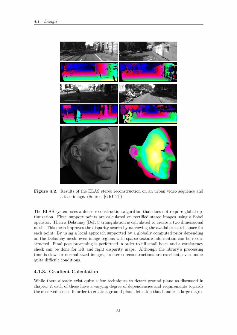
4.1. Design
Figure 4.2.: Results of the ELAS stereo reconstruction on an urban video sequence anda face image. (Source: [GRU11])
The ELAS system uses a dense reconstruction algorithm that does not require global op-timization. First, support points are calculated on rectified stereo images using a Sobeloperator. Then a Delaunay [Del34] triangulation is calculated to create a two dimensionalmesh. This mesh improves the disparity search by narrowing the available search space foreach point. By using a local approach supported by a globally computed prior dependingon the Delaunay mesh, even image regions with sparse texture information can be recon-structed. Final post processing is performed in order to fill small holes and a consistencycheck can be done for left and right disparity maps. Although the library’s processingtime is slow for normal sized images, its stereo reconstructions are excellent, even underquite difficult conditions.
4.1.3. Gradient Calculation
While there already exist quite a few techniques to detect ground plane as discussed inchapter 2, each of these have a varying degree of dependencies and requirements towardsthe observed scene. In order to create a ground plane detection that handles a large degree
31
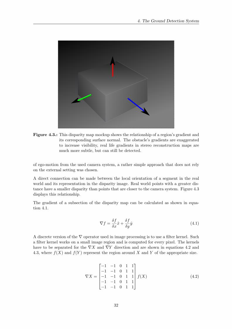
4. The Ground Detection System
Figure 4.3.: This disparity map mockup shows the relationship of a region’s gradient andits corresponding surface normal. The obstacle’s gradients are exaggeratedto increase visibility, real life gradients in stereo reconstruction maps aremuch more subtle, but can still be detected.
of ego-motion from the used camera system, a rather simple approach that does not relyon the external setting was chosen.
A direct connection can be made between the local orientation of a segment in the realworld and its representation in the disparity image. Real world points with a greater dis-tance have a smaller disparity than points that are closer to the camera system. Figure 4.3displays this relationship.
The gradient of a subsection of the disparity map can be calculated as shown in equa-tion 4.1.
∇f =δf
δxx+
δf
δyy (4.1)
A discrete version of the ∇ operator used in image processing is to use a filter kernel. Sucha filter kernel works on a small image region and is computed for every pixel. The kernelshave to be separated for the ∇X and ∇Y direction and are shown in equations 4.2 and4.3, where f(X) and f(Y ) represent the region around X and Y of the appropriate size.
∇X =
−1 −1 0 1 1−1 −1 0 1 1−1 −1 0 1 1−1 −1 0 1 1−1 −1 0 1 1
f(X) (4.2)
32
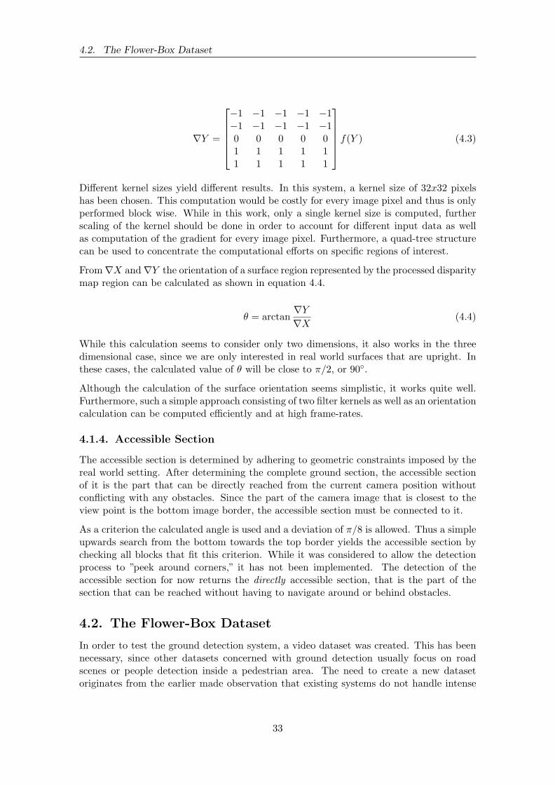
4.2. The Flower-Box Dataset
∇Y =
−1 −1 −1 −1 −1−1 −1 −1 −1 −10 0 0 0 01 1 1 1 11 1 1 1 1
f(Y ) (4.3)
Different kernel sizes yield different results. In this system, a kernel size of 32x32 pixelshas been chosen. This computation would be costly for every image pixel and thus is onlyperformed block wise. While in this work, only a single kernel size is computed, furtherscaling of the kernel should be done in order to account for different input data as wellas computation of the gradient for every image pixel. Furthermore, a quad-tree structurecan be used to concentrate the computational efforts on specific regions of interest.
From∇X and∇Y the orientation of a surface region represented by the processed disparitymap region can be calculated as shown in equation 4.4.
θ = arctan∇Y
∇X(4.4)
While this calculation seems to consider only two dimensions, it also works in the threedimensional case, since we are only interested in real world surfaces that are upright. Inthese cases, the calculated value of θ will be close to π/2, or 90◦.
Although the calculation of the surface orientation seems simplistic, it works quite well.Furthermore, such a simple approach consisting of two filter kernels as well as an orientationcalculation can be computed efficiently and at high frame-rates.
4.1.4. Accessible Section
The accessible section is determined by adhering to geometric constraints imposed by thereal world setting. After determining the complete ground section, the accessible sectionof it is the part that can be directly reached from the current camera position withoutconflicting with any obstacles. Since the part of the camera image that is closest to theview point is the bottom image border, the accessible section must be connected to it.
As a criterion the calculated angle is used and a deviation of π/8 is allowed. Thus a simpleupwards search from the bottom towards the top border yields the accessible section bychecking all blocks that fit this criterion. While it was considered to allow the detectionprocess to ”peek around corners,” it has not been implemented. The detection of theaccessible section for now returns the directly accessible section, that is the part of thesection that can be reached without having to navigate around or behind obstacles.
4.2. The Flower-Box Dataset
In order to test the ground detection system, a video dataset was created. This has beennecessary, since other datasets concerned with ground detection usually focus on roadscenes or people detection inside a pedestrian area. The need to create a new datasetoriginates from the earlier made observation that existing systems do not handle intense
33

4. The Ground Detection System
camera movement well. Thus, a dataset has been created where an intense ego-motioncan be observed.
The dataset consists of 20 videos of varying length. These videos cover an array of differentscenes and objects, such as sidewalks or walkways with parked cars or bicycles, a fewpedestrians or cyclists and street poles as well as a few edge cases such as a ladder likesculpture and a narrow ridge. A complete overview of the dataset is given in table 4.4.Some key frames of each video can be seen in figures 4.5 and 4.6.
4.2.1. Acquisition
The dataset has been recorded using a hand-held stereo camera rig and a laptop. Thiscamera system is comprised of two Point Grey Grasshopper 2 cameras mounted onto ametal carrier at a fixed distance. These cameras can record images at up to 2448x2048with 15 frames per second or smaller resolutions at higher frame rates. Due to technicallimitations the dataset could not be recorded using the fully available frame rate andresolution. The used laptop, a MacBook Pro 7.1, possesses only a single FireWire portto connect to the cameras. Luckily, these can be daisy-chained, which also brings theadded benefit of camera synchronization, especially important in stereo reconstructionscenarios. Due to these hardware limitations, the dataset has been recorded at a resolutionof 1028x768 pixels and 15 frames per second in 8-bit grey mode.
The videos were recorded within a duration of two hours on a sunny day inside an urbanarea. They were not captured in one session and the listed videos of table 4.4 are not sortedby time, but by content. Altogether, the videos add up to almost nine minutes of videodata. Also, much care has been taken to record the videos under realistic settings. Directsunlight, weak lens flares and strong shadows can be seen in the videos. Furthermorethere is much camera movement on all axes to simulate a mobile platform carried by apedestrian.
A calibration has been obtained before and after the recording of the dataset to mitigatethe possibility of an unintended change in the relative camera position due to outsideforces. No modification was detected.
In order to improve the stereo reconstruction, several precautionary measures have beentaken. The cameras’ optical axes are aligned to be parallel. Both cameras record in asynchronized manner through the use of a built-in synchronization mechanism over theFireWire bus. Also, the cameras gains and exposures are synced to create stereo imageswith similar illumination and contrast.
4.2.2. Labeling Process
Together, all videos contain 7789 frames. Every fifth frame has been labeled, that amountsto three labeled frames per second. Furthermore, the first 30 frames (or two seconds) ofeach video were not labeled to account for camera initialization of gain and exposure,which adds up to a reduction of 100 labeled frames.
To simplify the labeling process, the videos were first converted into their individual frames.After excluding undesired frames, the remaining were then labeled by hand using a specif-ically created labeling tool using the matrix laboratory (MATLAB) environment. This
34
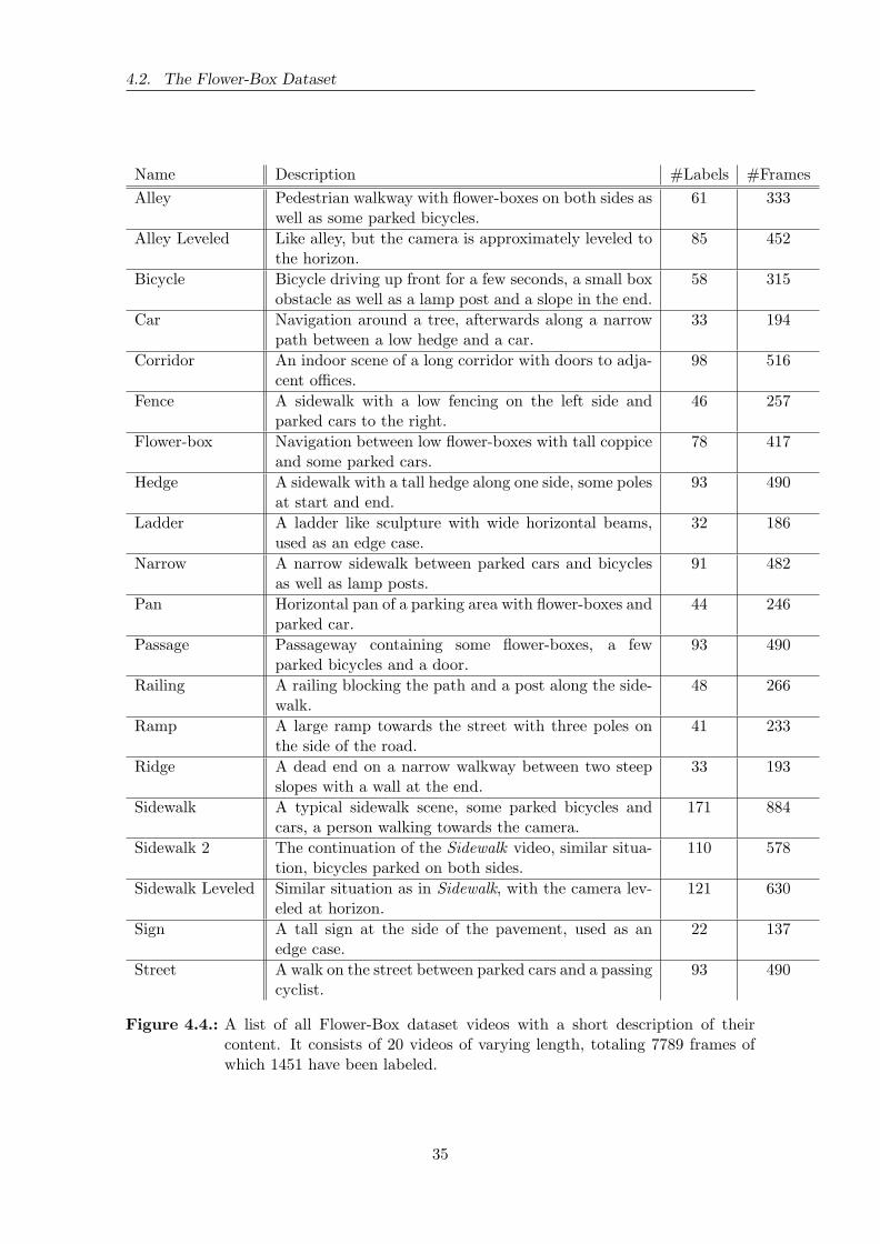
4.2. The Flower-Box Dataset
Name Description #Labels #Frames
Alley Pedestrian walkway with flower-boxes on both sides aswell as some parked bicycles.
61 333
Alley Leveled Like alley, but the camera is approximately leveled tothe horizon.
85 452
Bicycle Bicycle driving up front for a few seconds, a small boxobstacle as well as a lamp post and a slope in the end.
58 315
Car Navigation around a tree, afterwards along a narrowpath between a low hedge and a car.
33 194
Corridor An indoor scene of a long corridor with doors to adja-cent offices.
98 516
Fence A sidewalk with a low fencing on the left side andparked cars to the right.
46 257
Flower-box Navigation between low flower-boxes with tall coppiceand some parked cars.
78 417
Hedge A sidewalk with a tall hedge along one side, some polesat start and end.
93 490
Ladder A ladder like sculpture with wide horizontal beams,used as an edge case.
32 186
Narrow A narrow sidewalk between parked cars and bicyclesas well as lamp posts.
91 482
Pan Horizontal pan of a parking area with flower-boxes andparked car.
44 246
Passage Passageway containing some flower-boxes, a fewparked bicycles and a door.
93 490
Railing A railing blocking the path and a post along the side-walk.
48 266
Ramp A large ramp towards the street with three poles onthe side of the road.
41 233
Ridge A dead end on a narrow walkway between two steepslopes with a wall at the end.
33 193
Sidewalk A typical sidewalk scene, some parked bicycles andcars, a person walking towards the camera.
171 884
Sidewalk 2 The continuation of the Sidewalk video, similar situa-tion, bicycles parked on both sides.
110 578
Sidewalk Leveled Similar situation as in Sidewalk, with the camera lev-eled at horizon.
121 630
Sign A tall sign at the side of the pavement, used as anedge case.
22 137
Street A walk on the street between parked cars and a passingcyclist.
93 490
Figure 4.4.: A list of all Flower-Box dataset videos with a short description of theircontent. It consists of 20 videos of varying length, totaling 7789 frames ofwhich 1451 have been labeled.
35
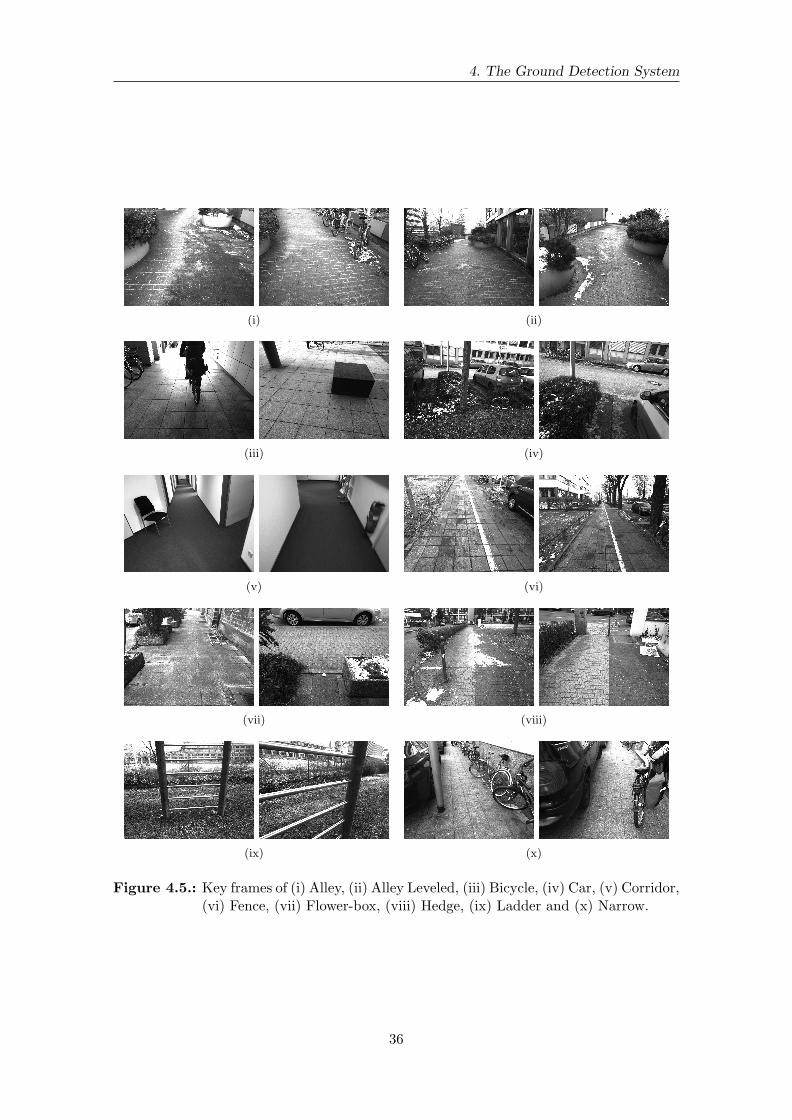
4. The Ground Detection System
(i) (ii)
(iii) (iv)
(v) (vi)
(vii) (viii)
(ix) (x)
Figure 4.5.: Key frames of (i) Alley, (ii) Alley Leveled, (iii) Bicycle, (iv) Car, (v) Corridor,(vi) Fence, (vii) Flower-box, (viii) Hedge, (ix) Ladder and (x) Narrow.
36
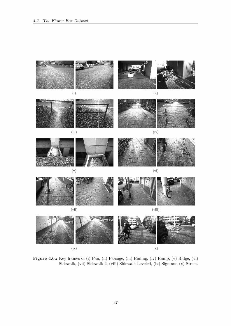
4.2. The Flower-Box Dataset
(i) (ii)
(iii) (iv)
(v) (vi)
(vii) (viii)
(ix) (x)
Figure 4.6.: Key frames of (i) Pan, (ii) Passage, (iii) Railing, (iv) Ramp, (v) Ridge, (vi)Sidewalk, (vii) Sidewalk 2, (viii) Sidewalk Leveled, (ix) Sign and (x) Street.
37
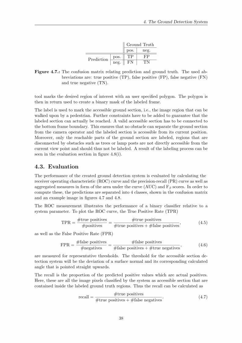
4. The Ground Detection System
Ground Truthpos. neg.
Predictionpos. TP FPneg. FN TN
Figure 4.7.: The confusion matrix relating prediction and ground truth. The used ab-breviations are: true positive (TP), false positive (FP), false negative (FN)and true negative (TN).
tool marks the desired region of interest with an user specified polygon. The polygon isthen in return used to create a binary mask of the labeled frame.
The label is used to mark the accessible ground section, i.e., the image region that can bewalked upon by a pedestrian. Further constraints have to be added to guarantee that thelabeled section can actually be reached. A valid accessible section has to be connected tothe bottom frame boundary. This ensures that no obstacle can separate the ground sectionfrom the camera operator and the labeled section is accessible from its current position.Moreover, only the reachable parts of the ground section are labeled, regions that aredisconnected by obstacles such as trees or lamp posts are not directly accessible from thecurrent view point and should thus not be labeled. A result of the labeling process can beseen in the evaluation section in figure 4.8(i).
4.3. Evaluation
The performance of the created ground detection system is evaluated by calculating thereceiver operating characteristic (ROC) curve and the precision-recall (PR) curve as well asaggregated measures in form of the area under the curve (AUC) and Fβ scores. In order tocompute these, the predictions are separated into 4 classes, shown in the confusion matrixand an example image in figures 4.7 and 4.8.
The ROC measurement illustrates the performance of a binary classifier relative to asystem parameter. To plot the ROC curve, the True Positive Rate (TPR)
TPR =#true positives
#positives=
#true positives
#true positives + #false positives, (4.5)
as well as the False Positive Rate (FPR)
FPR =#false positives
#negatives=
#false positives
#false positives + #true negatives, (4.6)
are measured for representative thresholds. The threshold for the accessible section de-tection system will be the deviation of a surface normal and its corresponding calculatedangle that is pointed straight upwards.
The recall is the proportion of the predicted positive values which are actual positives.Here, these are all the image pixels classified by the system as accessible section that arecontained inside the labeled ground truth regions. Thus the recall can be calculated as
recall =#true positives
#true positives + #false negatives. (4.7)
38

4.3. Evaluation
(i) (ii)
Figure 4.8.: An example of the four prediction classes. The original image (i) with theaccessible section outlined in red. The bottom image (ii) shows the pre-diction with the individual classes which are the correctly identified section(true positive) in green, the missed parts (false negatives) in yellow, falseidentified parts (false positives) in red and the remainder of the scene (truenegative) in blue.
The precision is the proportion of correct matches relative to the false and correct matches,
precision =#true positives
#true positives + #false positives. (4.8)
The Fβ score combines precision and recall into a single value, their individual weightsdetermined by β,
Fβ = (1 + β2) ·precision · recall
(β2 · precision) + recall. (4.9)
When evenly weighted, the F-score becomes the balanced F-measure, also known as theF1 score,
F1 = 2 ·precision · recall
precision + recall. (4.10)
Additionally, in the following F0.5 will be used, as it places a higher importance on precisionthan recall. A high precision seems more relevant than a high recall in this application,since it correlates with a high percentage of correct results with few false positives. Thisis especially important when dealing with a system that directly affects a human being,as it seems preferable to detect all obstacles rather than all of the accessible section.
Finally, the overall accuracy for each video is calculated as
accuracy =#true positives + #true negatives
#true positives + #true negatives + #false positives + #false negatives.
(4.11)
39
4. The Ground Detection System
4.4. Results
The created accessible section detection achieves varying results depending on circum-stances like the amount of observable ground plane or its texture. Three good classifica-tion results can be seen in figure 4.9, one indoor and two outdoor scenes. These threesettings constitute common scenarios for a navigational support system for visually im-paired persons. The outdoor scenes contain a sidewalk, once narrowed by parked cars andbicycles and once mainly free of obstacles. In these and similar scenarios, where there isa great variability in the texture of the observed scene, the classification achieves goodresults. This is due to the fact that the stereo reconstruction algorithm provides a stableand gap-less disparity map which in turn leads to a good classification.
In figure 4.10 three bad classification results can be seen. The system fails these situationsand only a small percentage of the accessible ground section is classified. Either the stereoreconstruction cannot deliver sufficient information or the classifier cannot deal with thecreated noise in the disparity map. Figure 4.11 shows such a case that is part of thePan video. Large holes and artefacts as well as strong noise in the disparity map causethe classification to fail on many image parts. Originally, 36 videos were recorded forthe data set, but almost half had to be discarded due to a poor stereo reconstructionquality. To further improve the classification method and discern between a failure on thesegmentation part, additional measures have to be taken. This could for example includethe development of a disparity map check of some sort.
Figures 4.12 and 4.13 show the per video averaged ROC and PR curves. Especially forthe Alley, Alley Leveled, Narrow, Sidewalk, Sidewalk 2, Sidewalk Leveled and Street videosa very high discrimination ratio is achieved, almost always above 90%. These videos havea fairly large stretch of accessible section with obstacles located on both sides in commonas well as only very few obstructions separating the ground section. Good results are alsoachieved on the Car, Corridor, Fence, Hedge, Ladder, Passage and Sign videos. Here,a variable amount of directly accessible ground section is available and it is often sepa-rated into several parts. Classification rates are still above 80% and support the initialassumption that the gradient classifier could deliver good results even under difficult cir-cumstances. The Bicycle, Flower-box, Pan, Railing and Ramp videos show the algorithm’slimits. Large parts of the ground section cannot be recognized. The worst detection ac-curacy is observed in the Ridge video. Much noise is created in the disparity map by thecombination of grass partly covered with snow, which has very low texture information.Furthermore, this video has by far the smallest amount of visible ground section whichcauses the algorithm to detect more false positives in relation to other videos.
An overview of the achieved classification rates for all videos is shown in figure 4.14 aswell as their standard deviation 4.15. The area under the curve (AUC) for ROC and PRare given as well as various F-scores. F0.5 and F1 scores show that the algorithm has ahigh reliability. Also, the small difference between the mean of the maximum and thefixed threshold F-scores and accuracies show that the selection of a general threshold ispossible.
40
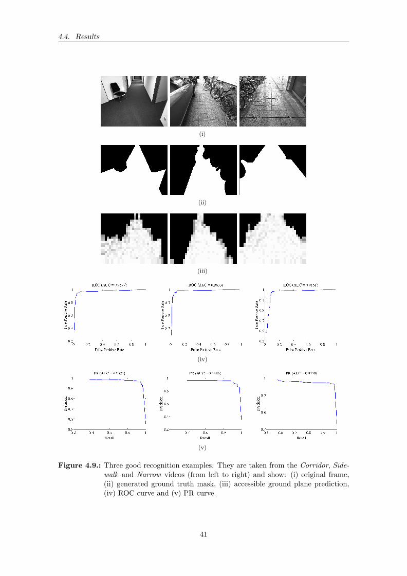
4.4. Results
(i)
(ii)
(iii)
(iv)
(v)
Figure 4.9.: Three good recognition examples. They are taken from the Corridor, Side-walk and Narrow videos (from left to right) and show: (i) original frame,(ii) generated ground truth mask, (iii) accessible ground plane prediction,(iv) ROC curve and (v) PR curve.
41

4. The Ground Detection System
(i)
(ii)
(iii)
(iv)
(v)
Figure 4.10.: Three bad recognition examples. They are taken from the Bicycle, Flower-box and Pan videos (from left to right) and show: (i) original frame, (ii)generated ground truth mask, (iii) accessible ground plane prediction, (iv)ROC curve and (v) PR curve.
42

4.4. Results
(i)
(ii)
(iii)
Figure 4.11.: Here a low recognition score is caused by a failing of the stereo reconstruc-tion algorithm. The images show the open area of a parking space (i), theproblems of the disparity map with large holes and artifacts (ii) and thefailing accessible section detection (iii).
43
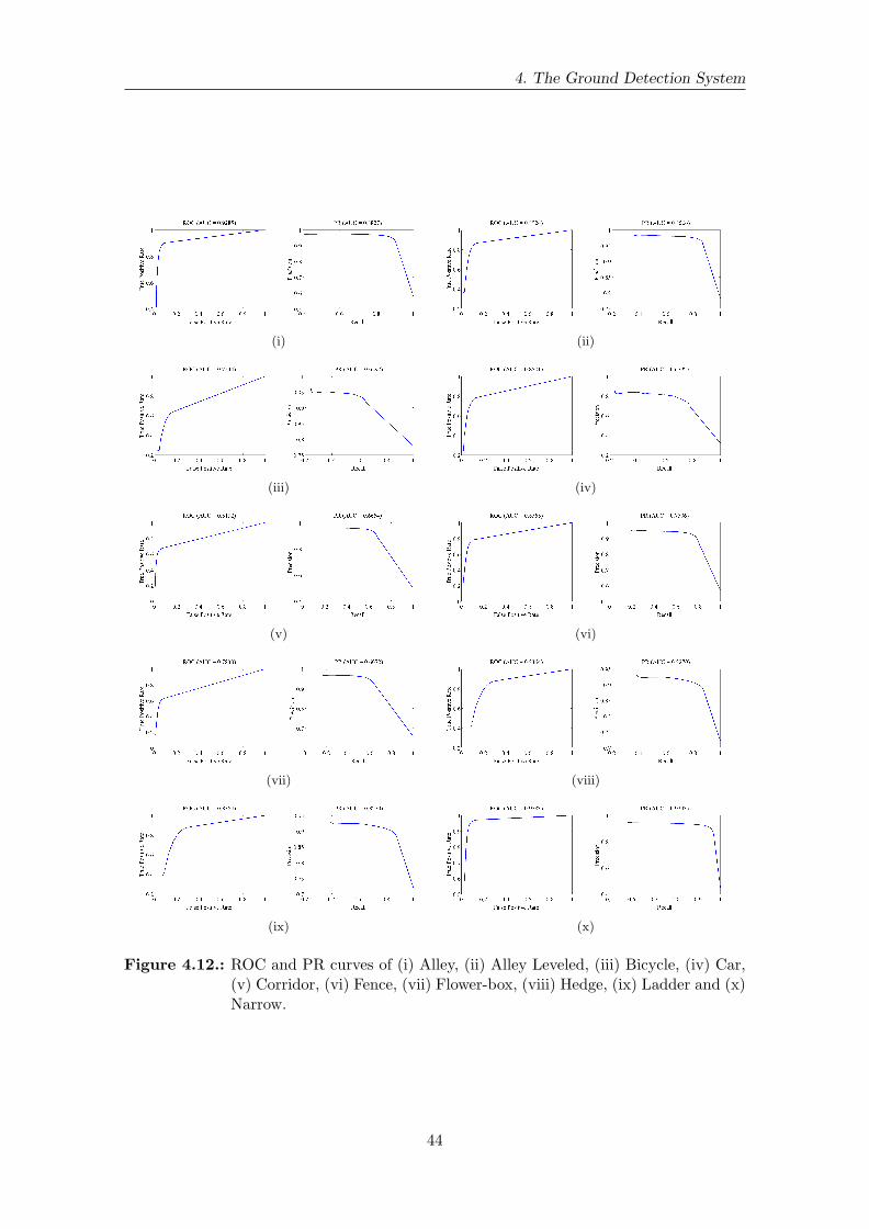
4. The Ground Detection System
(i) (ii)
(iii) (iv)
(v) (vi)
(vii) (viii)
(ix) (x)
Figure 4.12.: ROC and PR curves of (i) Alley, (ii) Alley Leveled, (iii) Bicycle, (iv) Car,(v) Corridor, (vi) Fence, (vii) Flower-box, (viii) Hedge, (ix) Ladder and (x)Narrow.
44

4.4. Results
(i) (ii)
(iii) (iv)
(v) (vi)
(vii) (viii)
(ix) (x)
Figure 4.13.: ROC and PR curves of (i) Pan, (ii) Passage, (iii) Railing, (iv) Ramp, (v)Ridge, (vi) Sidewalk, (vii) Sidewalk 2, (viii) Sidewalk Leveled, (ix) Signand (x) Street.
45
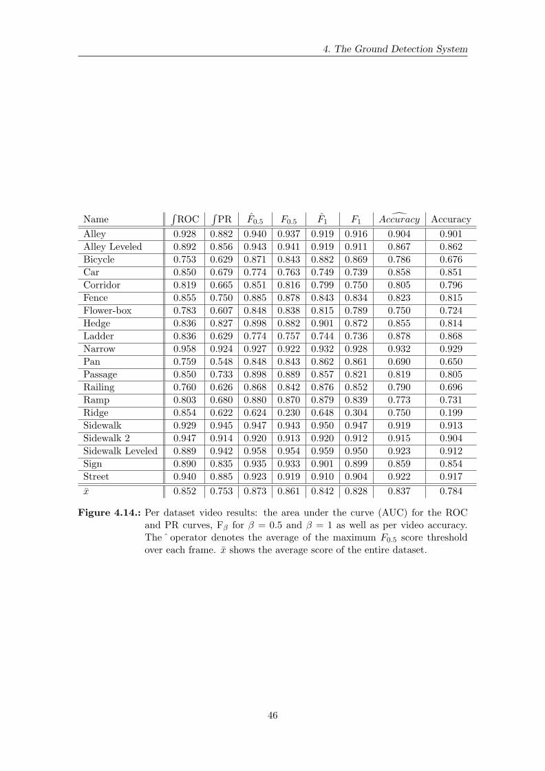
4. The Ground Detection System
Name∫ROC
∫PR F0.5 F0.5 F1 F1
Accuracy Accuracy
Alley 0.928 0.882 0.940 0.937 0.919 0.916 0.904 0.901
Alley Leveled 0.892 0.856 0.943 0.941 0.919 0.911 0.867 0.862
Bicycle 0.753 0.629 0.871 0.843 0.882 0.869 0.786 0.676
Car 0.850 0.679 0.774 0.763 0.749 0.739 0.858 0.851
Corridor 0.819 0.665 0.851 0.816 0.799 0.750 0.805 0.796
Fence 0.855 0.750 0.885 0.878 0.843 0.834 0.823 0.815
Flower-box 0.783 0.607 0.848 0.838 0.815 0.789 0.750 0.724
Hedge 0.836 0.827 0.898 0.882 0.901 0.872 0.855 0.814
Ladder 0.836 0.629 0.774 0.757 0.744 0.736 0.878 0.868
Narrow 0.958 0.924 0.927 0.922 0.932 0.928 0.932 0.929
Pan 0.759 0.548 0.848 0.843 0.862 0.861 0.690 0.650
Passage 0.850 0.733 0.898 0.889 0.857 0.821 0.819 0.805
Railing 0.760 0.626 0.868 0.842 0.876 0.852 0.790 0.696
Ramp 0.803 0.680 0.880 0.870 0.879 0.839 0.773 0.731
Ridge 0.854 0.622 0.624 0.230 0.648 0.304 0.750 0.199
Sidewalk 0.929 0.945 0.947 0.943 0.950 0.947 0.919 0.913
Sidewalk 2 0.947 0.914 0.920 0.913 0.920 0.912 0.915 0.904
Sidewalk Leveled 0.889 0.942 0.958 0.954 0.959 0.950 0.923 0.912
Sign 0.890 0.835 0.935 0.933 0.901 0.899 0.859 0.854
Street 0.940 0.885 0.923 0.919 0.910 0.904 0.922 0.917
x 0.852 0.753 0.873 0.861 0.842 0.828 0.837 0.784
Figure 4.14.: Per dataset video results: the area under the curve (AUC) for the ROCand PR curves, Fβ for β = 0.5 and β = 1 as well as per video accuracy.The ˆ operator denotes the average of the maximum F0.5 score thresholdover each frame. x shows the average score of the entire dataset.
46
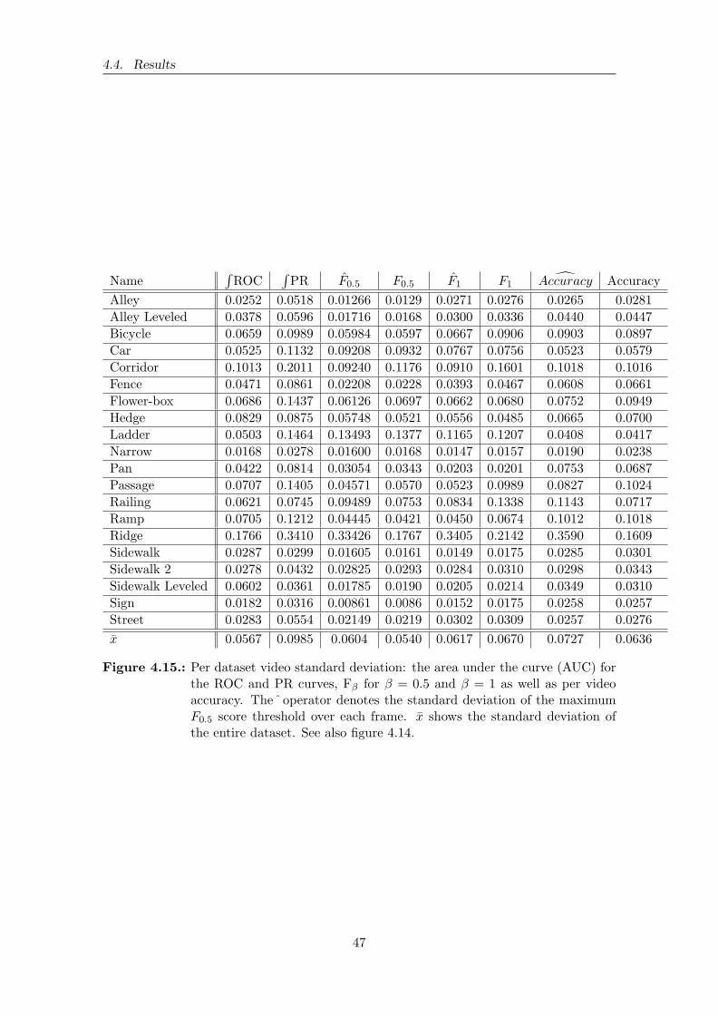
4.4. Results
Name∫ROC
∫PR F0.5 F0.5 F1 F1
Accuracy Accuracy
Alley 0.0252 0.0518 0.01266 0.0129 0.0271 0.0276 0.0265 0.0281
Alley Leveled 0.0378 0.0596 0.01716 0.0168 0.0300 0.0336 0.0440 0.0447
Bicycle 0.0659 0.0989 0.05984 0.0597 0.0667 0.0906 0.0903 0.0897
Car 0.0525 0.1132 0.09208 0.0932 0.0767 0.0756 0.0523 0.0579
Corridor 0.1013 0.2011 0.09240 0.1176 0.0910 0.1601 0.1018 0.1016
Fence 0.0471 0.0861 0.02208 0.0228 0.0393 0.0467 0.0608 0.0661
Flower-box 0.0686 0.1437 0.06126 0.0697 0.0662 0.0680 0.0752 0.0949
Hedge 0.0829 0.0875 0.05748 0.0521 0.0556 0.0485 0.0665 0.0700
Ladder 0.0503 0.1464 0.13493 0.1377 0.1165 0.1207 0.0408 0.0417
Narrow 0.0168 0.0278 0.01600 0.0168 0.0147 0.0157 0.0190 0.0238
Pan 0.0422 0.0814 0.03054 0.0343 0.0203 0.0201 0.0753 0.0687
Passage 0.0707 0.1405 0.04571 0.0570 0.0523 0.0989 0.0827 0.1024
Railing 0.0621 0.0745 0.09489 0.0753 0.0834 0.1338 0.1143 0.0717
Ramp 0.0705 0.1212 0.04445 0.0421 0.0450 0.0674 0.1012 0.1018
Ridge 0.1766 0.3410 0.33426 0.1767 0.3405 0.2142 0.3590 0.1609
Sidewalk 0.0287 0.0299 0.01605 0.0161 0.0149 0.0175 0.0285 0.0301
Sidewalk 2 0.0278 0.0432 0.02825 0.0293 0.0284 0.0310 0.0298 0.0343
Sidewalk Leveled 0.0602 0.0361 0.01785 0.0190 0.0205 0.0214 0.0349 0.0310
Sign 0.0182 0.0316 0.00861 0.0086 0.0152 0.0175 0.0258 0.0257
Street 0.0283 0.0554 0.02149 0.0219 0.0302 0.0309 0.0257 0.0276
x 0.0567 0.0985 0.0604 0.0540 0.0617 0.0670 0.0727 0.0636
Figure 4.15.: Per dataset video standard deviation: the area under the curve (AUC) forthe ROC and PR curves, Fβ for β = 0.5 and β = 1 as well as per videoaccuracy. Theˆoperator denotes the standard deviation of the maximumF0.5 score threshold over each frame. x shows the standard deviation ofthe entire dataset. See also figure 4.14.
47


5. Conclusion
The existence of numerous frameworks for various research purposes indicates the need ofa common base to foster collaboration among researchers. However, due to their devel-opment towards a particular purpose, they often contain many parts that are not neededin other research areas and may become hard to use in a different scenario. Thus, in thisthesis, a framework aimed towards visually impaired persons has been presented with a fo-cus on simplicity and ease of use by other research students. The frameworks main designgoals: modularity, versatility, functionality, encapsulation and provision of core compo-nents have greatly helped in the development process of a walkable area detection systemfor visually impaired persons. By reusing already existing framework components, muchdevelopment time was saved. Furthermore, the framework could be tested with regard toits ease of use and flexibility. It can be concluded that the framework justifies its investedwork. Already, a few useful modules have been developed by other student researchersfrom the same laboratory.
While there already exist many ground plane detection systems, such systems were usuallydeveloped taking into account several artificially enforced constraints. Conditions such asknowledge about the exact camera position were used as well as the existence of specificmarkers, amongst others. This dependency upon external constraints renders them un-feasible for visually impaired persons, as these cannot be guaranteed. Thus, a simple andeffective feature has been introduced, the gradient detection inside a disparity map pro-duced by a stereo reconstruction algorithm. The gradient uses the correlation between theorientation of a surface in the real world and its representation in the acquired disparitymap. Its calculation is neither complex nor computationally expensive and can thus bedone fast and efficiently. In addition, a simple detector to retrieve the accessible sectionwas created. This detector relies on a few simple geometric constraints to process thedetected ground region. The simple approach of the ground detection system yields sur-prisingly effective classifications, but can only be seen as a small step towards a reliablenavigation system for visually impaired persons.
A real world dataset was created to evaluate the developed ground detection system. Itwas collected inside an urban area using a hand held stereo camera rig and a laptop.
49
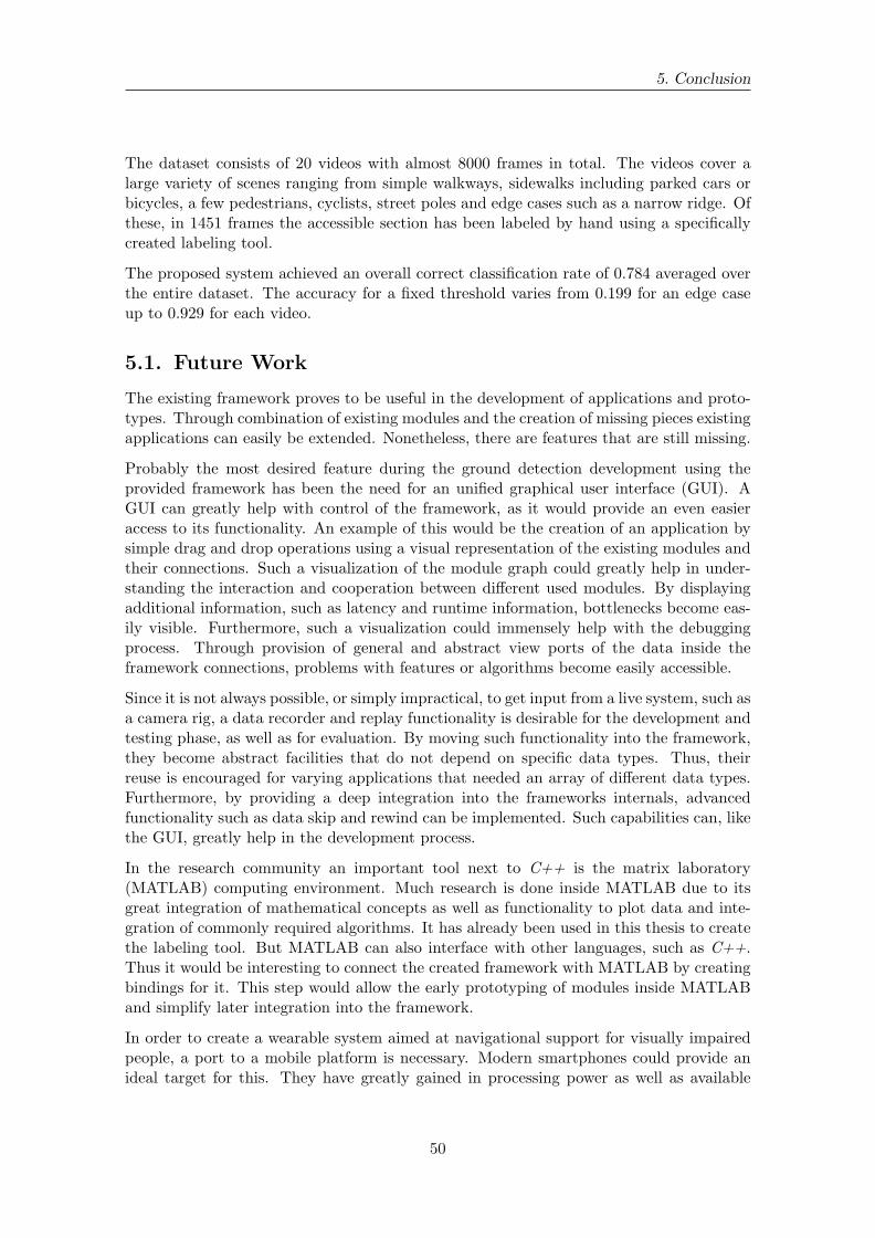
5. Conclusion
The dataset consists of 20 videos with almost 8000 frames in total. The videos cover alarge variety of scenes ranging from simple walkways, sidewalks including parked cars orbicycles, a few pedestrians, cyclists, street poles and edge cases such as a narrow ridge. Ofthese, in 1451 frames the accessible section has been labeled by hand using a specificallycreated labeling tool.
The proposed system achieved an overall correct classification rate of 0.784 averaged overthe entire dataset. The accuracy for a fixed threshold varies from 0.199 for an edge caseup to 0.929 for each video.
5.1. Future Work
The existing framework proves to be useful in the development of applications and proto-types. Through combination of existing modules and the creation of missing pieces existingapplications can easily be extended. Nonetheless, there are features that are still missing.
Probably the most desired feature during the ground detection development using theprovided framework has been the need for an unified graphical user interface (GUI). AGUI can greatly help with control of the framework, as it would provide an even easieraccess to its functionality. An example of this would be the creation of an application bysimple drag and drop operations using a visual representation of the existing modules andtheir connections. Such a visualization of the module graph could greatly help in under-standing the interaction and cooperation between different used modules. By displayingadditional information, such as latency and runtime information, bottlenecks become eas-ily visible. Furthermore, such a visualization could immensely help with the debuggingprocess. Through provision of general and abstract view ports of the data inside theframework connections, problems with features or algorithms become easily accessible.
Since it is not always possible, or simply impractical, to get input from a live system, such asa camera rig, a data recorder and replay functionality is desirable for the development andtesting phase, as well as for evaluation. By moving such functionality into the framework,they become abstract facilities that do not depend on specific data types. Thus, theirreuse is encouraged for varying applications that needed an array of different data types.Furthermore, by providing a deep integration into the frameworks internals, advancedfunctionality such as data skip and rewind can be implemented. Such capabilities can, likethe GUI, greatly help in the development process.
In the research community an important tool next to C++ is the matrix laboratory(MATLAB) computing environment. Much research is done inside MATLAB due to itsgreat integration of mathematical concepts as well as functionality to plot data and inte-gration of commonly required algorithms. It has already been used in this thesis to createthe labeling tool. But MATLAB can also interface with other languages, such as C++.Thus it would be interesting to connect the created framework with MATLAB by creatingbindings for it. This step would allow the early prototyping of modules inside MATLABand simplify later integration into the framework.
In order to create a wearable system aimed at navigational support for visually impairedpeople, a port to a mobile platform is necessary. Modern smartphones could provide anideal target for this. They have greatly gained in processing power as well as available
50

5.1. Future Work
memory over the years and also contain high resolution cameras. The Android platformseems especially suited for this purpose, since it is open source and widely used.
Ways of providing feedback to the user must also be explored. Through haptic interfaces,such as the Vibrotac [SEWP10] device, guidance information could be passed along. Soni-fication could also provide such a feedback system, but the feasibility of any approach mustbe examined first. Integration of such systems is an important step towards the creationof usable navigation support systems.
The ground detection system can be further improved by evolving the gradient and thedetection of the accessible system using quadtree like structures and varying gradientkernel sizes. By processing the disparity map with such improvements, the focus could beconcentrated on regions of interest and thus a finer grained representation of the groundplane could be acquired. Furthermore, using a three dimensional representation could helpin specifically difficult situations. Various approaches, such as simultaneous localizationand mapping (SLAM) [Dav03], dense tracking and mapping (DTAM) [NLD11] and paralleltracking and mapping (PTAM) [KM09] already exist, although their feasibility on mobileplatforms remain to be tested due to high complexity and processing requirements.
51


Bibliography
[BBK+01] M. Bauer, B. Bruegge, G. Klinker, A. MacWilliams, T. Reicher, S. Riss,C. Sandor, and M. Wagner, “Design of a component-based augmented re-ality framework,” in Augmented Reality, 2001. Proceedings. IEEE and ACMInternational Symposium on, 2001, pp. 45–54.
[BPCL06] C. Braillon, C. Pradalier, J. Crowley, and C. Laugier, “Real-time moving ob-stacle detection using optical flow models,” in Intelligent Vehicles Symposium,2006 IEEE, 0-0 2006, pp. 466–471.
[BWC01] D. Beazley, B. Ward, and I. Cooke, “The inside story on shared libraries anddynamic loading,”Computing in Science Engineering, vol. 3, no. 5, pp. 90–97,sep/oct 2001.
[CFZ+12] D. Chen, W. Feng, Q. Zhao, M. Hu, and T. Wang, “An infrastructure-freeindoor navigation system for blind people,” Intelligent Robotics and Applica-tions, pp. 552–561, 2012.
[CM09] J. Coughlan and R. Manduchi, “A mobile phone wayfinding system for visuallyimpaired users,”Assistive technology research series, vol. 25, no. 2009, p. 849,2009.
[CMG05] T. H. Collett, B. A. MacDonald, and B. P. Gerkey, “Player 2.0: Toward apractical robot programming framework,” in Proceedings of the AustralasianConference on Robotics and Automation (ACRA 2005), 2005.
[CTV05] S. Cardin, D. Thalmann, and F. Vexo, “Wearable obstacle detection systemfor visually impaired people,” in VR workshop on haptic and tactile perceptionof deformable objects, 2005, pp. 50–55.
[CVH08] N. Chumerin and M. M. Van Hulle, “Ground plane estimation based on densestereo disparity,” in The Fifth International Conference on Neural Networksand artificial intelligence, Minsk, Belarus, 2008, pp. 209–213.
[Dav03] A. Davison, “Real-time simultaneous localisation and mapping with a singlecamera,” in Computer Vision, 2003. Proceedings. Ninth IEEE InternationalConference on, oct. 2003, pp. 1403 –1410 vol.2.
[Del34] B. Delaunay, “Sur la sphere vide,” Izv. Akad. Nauk SSSR, Otdelenie Matem-aticheskii i Estestvennyka Nauk, vol. 7, no. 793-800, pp. 1–2, 1934.
[DH72] R. O. Duda and P. E. Hart, “Use of the hough transformation to detect linesand curves in pictures,”Communications of the ACM, vol. 15, no. 1, pp. 11–15,1972.
53
Bibliography
[DK08] R. Diankov and J. Kuffner, “Openrave: A planning architecture for au-tonomous robotics,” Robotics Institute, Pittsburgh, PA, Tech. Rep. CMU-RI-TR-08-34, 2008.
[ELSVG09] A. Ess, B. Leibe, K. Schindler, and L. Van Gool, “Moving obstacle detection inhighly dynamic scenes,” in Robotics and Automation, 2009. ICRA ’09. IEEEInternational Conference on, may 2009, pp. 56–63.
[ESLVG10] A. Ess, K. Schindler, B. Leibe, and L. Van Gool, “Object detection and track-ing for autonomous navigation in dynamic environments,” The InternationalJournal of Robotics Research, vol. 29, no. 14, pp. 1707–1725, 2010.
[FB81] M. A. Fischler and R. C. Bolles, “Random sample consensus: a paradigm formodel fitting with applications to image analysis and automated cartography,”Communications of the ACM, vol. 24, no. 6, pp. 381–395, 1981.
[GRU11] A. Geiger, M. Roser, and R. Urtasun, “Efficient large-scale stereo matching,”Computer Vision–ACCV 2010, pp. 25–38, 2011.
[GVH03] B. Gerkey, R. T. Vaughan, and A. Howard, “The player/stage project: Toolsfor multi-robot and distributed sensor systems,” in Proceedings of the 11thinternational conference on advanced robotics, vol. 1. Portugal, 2003, pp.317–323.
[GVS+01] B. Gerkey, R. Vaughan, K. Stoy, A. Howard, G. Sukhatme, and M. Mataric,“Most valuable player: a robot device server for distributed control,” in Intel-ligent Robots and Systems, 2001. Proceedings. 2001 IEEE/RSJ InternationalConference on, vol. 3, 2001, pp. 1226–1231.
[HLM12] Y. Hoon, L. T.-s. Leung, and G. Medioni, “Real-time staircase detection froma wearable stereo system,” ICPR - International Conference on Pattern Recog-nition, pp. 6–9, 2012.
[Hra08] S. Hrabar, “3d path planning and stereo-based obstacle avoidance for rotor-craft uavs,” in Intelligent Robots and Systems, 2008. IROS 2008. IEEE/RSJInternational Conference on, sept. 2008, pp. 807–814.
[HS81] B. K. Horn and B. G. Schunck, “Determining optical flow,” Artificial intelli-gence, vol. 17, no. 1, pp. 185–203, 1981.
[HW77] P. W. Holland and R. E. Welsch, “Robust regression using iterativelyreweighted least-squares,”Communications in Statistics-Theory and Methods,vol. 6, no. 9, pp. 813–827, 1977.
[Kat02] H. Kato, “Artoolkit: Library for vision-based augmented reality,” IEICE,PRMU, pp. 79–86, 2002.
[KM09] G. Klein and D. Murray, “Parallel tracking and mapping on a camera phone,”in Mixed and Augmented Reality, 2009. ISMAR 2009. 8th IEEE InternationalSymposium on, oct. 2009, pp. 83 –86.
[LAT02] R. Labayrade, D. Aubert, and J.-P. Tarel, “Real time obstacle detection instereovision on non flat road geometry through ”v-disparity” representation,”in Intelligent Vehicle Symposium, 2002. IEEE, vol. 2, june 2002, pp. 646–651.
54

Bibliography
[LM11] Y. H. Lee and G. Medioni, “Rgb-d camera based navigation for the visuallyimpaired.” Robotic Science and Systems, 2011.
[LPB12] M. C. Le, S. L. Phung, and A. Bouzerdoum, “Pedestrian lane detection for thevisually impaired,” in Digital Image Computing Techniques and Applications(DICTA), 2012 International Conference on, dec. 2012, pp. 1–6.
[LSC12] C.-H. Lee, Y.-C. Su, and L.-G. Chen, “An intelligent depth-based obstacle de-tection system for visually-impaired aid applications,” in Image Analysis forMultimedia Interactive Services (WIAMIS), 2012 13th International Work-shop on, may 2012, pp. 1–4.
[LZM05] P. Lombardi, M. Zanin, and S. Messelodi, “Unified stereovision for ground,road, and obstacle detection,” in Intelligent Vehicles Symposium, 2005. Pro-ceedings. IEEE, june 2005, pp. 783–788.
[MH08] K. Martin and B. Hoffman, Mastering CMake 4th Edition. Kitware, Inc.,2008.
[ML12] D. Mitzel and B. Leibe, “Close-Range Human Detection for Head-MountedCameras,” The British Machine Vision Association and Society for PatternRecognition, pp. 1–11, 2012.
[MR+08] J. M. S. Martinez, F. E. Ruiz et al., “Stereo-based aerial obstacle detectionfor the visually impaired,” in Workshop on Computer Vision Applications forthe Visually Impaired, 2008.
[MRT03] M. Montemerlo, N. Roy, and S. Thrun, “Perspectives on standardization inmobile robot programming: the carnegie mellon navigation (carmen) toolkit,”in Intelligent Robots and Systems, 2003. (IROS 2003). Proceedings. 2003IEEE/RSJ International Conference on, vol. 3, oct. 2003, pp. 2436–2441.
[NLD11] R. Newcombe, S. Lovegrove, and A. Davison, “Dtam: Dense tracking andmapping in real-time,” in Computer Vision (ICCV), 2011 IEEE InternationalConference on, nov. 2011, pp. 2320 –2327.
[OR12] C. Olson and A. Robinson, “Camera-aided human navigation: Advances andchallenges,” in Emerging Signal Processing Applications (ESPA), 2012 IEEEInternational Conference on, jan. 2012, pp. 75–78.
[QGC+09] M. Quigley, B. Gerkey, K. Conley, J. Faust, T. Foote, J. Leibs, E. Berger,R. Wheeler, and A. Ng, “Ros: an open-source robot operating system,” inICRA workshop on open source software, vol. 3, no. 3.2, 2009.
[SB02] S. Se and M. Brady, “Ground plane estimation, error analysis and applica-tions,”Robotics and Autonomous Systems, vol. 39, no. 2, pp. 59–71, 2002.
[SEWP10] S. Schaetzle, T. Ende, T. Wuesthoff, and C. Preusche, “Vibrotac: An er-gonomic and versatile usable vibrotactile feedback device,” in RO-MAN, 2010IEEE, sept. 2010, pp. 670 –675.
[SGCH01] K. J. Sullivan, W. G. Griswold, Y. Cai, and B. Hallen, “The structure andvalue of modularity in software design,”ACM SIGSOFT Software EngineeringNotes, vol. 26, no. 5, p. 99, Sep. 2001.
55

Bibliography
[Ste11] M. Stevens,“Subaru eyesight coming to australia for liberty and outback in late2011,” 2011. [Online]. Available: http://www.themotorreport.com.au/51481/subaru-eyesight-coming-to-australia-for-liberty-and-outback-in-late-2011
[Str93] B. Stroustrup, “New Casts Revisited,” 1993. [Online]. Available: http://www.open-std.org/jtc1/sc22/wg21/docs/papers/1993/N0349a.pdf
[SUB03] S. Shoval, I. Ulrich, and J. Borenstein, “Navbelt and the guide-cane [obstacle-avoidance systems for the blind and visually impaired],”Robotics AutomationMagazine, IEEE, vol. 10, no. 1, pp. 9–20, mar 2003.
[Sut09] H. Sutter, “The Fast Pimpl Idiom,” 2009. [Online]. Available: http://www.gotw.ca/gotw/028.htm
[Su10] Sudostschweiz.ch, “Am Tag des Weissen Stocks testen Blinde dieAnhaltedisziplin,” 2010. [Online]. Available: http://www.suedostschweiz.ch/vermischtes/am-tag-des-weissen-stocks-testen-blinde-die-anhaltedisziplin
[TH05] L. Torvalds and J. Hamano, “GIT-fast version control system,” 2005. [Online].Available: www.git-scm.com
[vH08] D. van Heesch, “Doxygen: Source code documentation generator tool,” 2008.[Online]. Available: www.doxygen.org
[Zel09] A. Zelinsky, “Learning opencv—computer vision with the opencv library(bradski, g.r. et al.; 2008)[on the shelf],” Robotics Automation Magazine,IEEE, vol. 16, no. 3, p. 100, september 2009.
56

Appendix
A. BVS System Overview
BVS::BVS+ shutdownHandler- moduleStack+ BVS()+ ~BVS()+ loadModules()+ loadModule()+ unloadModules()+ unloadModule()+ connectAllModules()+ connectModule()+ loadConfigFile()+ setLogSystemVerbosity()and 10 more...- BVS()- operator=()
BVS::Connector< T >- connection- data+ Connector()+ Connector()+ ~Connector()+ send()+ receive()+ operator*()+ operator->()+ lockConnection()+ unlockConnection()- activate()- operator=()
BVS::Module
+ Module()+ ~Module()+ execute()+ debugDisplay()- Module()- operator=()
Figure A.1.: These are BVS’ main interfaces. On the left, the client interface can beseen. It is used to control the framework and interact with its parts. Inthe middle, the module interface used by the framework to interact witheach module is shown. On the right, the module connector template usedby module connections is displayed.
57
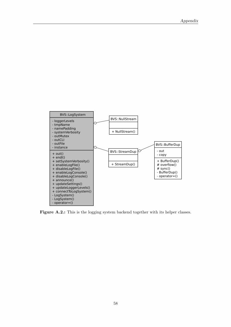
Appendix
BVS::LogSystem- loggerLevels- tmpName- namePadding- systemVerbosity- outMutex- outCLI- outFile- instance+ out()+ endl()+ setSystemVerbosity()+ enableLogFile()+ disableLogFile()+ enableLogConsole()+ disableLogConsole()+ announce()+ updateSettings()+ updateLoggerLevels()+ connectToLogSystem()- LogSystem()- LogSystem()- operator=()
BVS::NullStream
+ NullStream()
BVS::StreamDup
+ StreamDup()
BVS::BufferDup- out- copy+ BufferDup()# overflow()# sync()- BufferDup()- operator=()
Figure A.2.: This is the logging system backend together with its helper classes.
58

A. BVS System Overview
BVS::ConnectorData+ id+ type+ active+ pointer+ typeIDHash+ typeIDName+ mutex+ lock+ locked+ ConnectorData()+ ConnectorData()+ operator=()
BVS::Control+ modules- activePools- pools- flag- masterLock- controlThread- round- shutdownRequested- shutdownRound+ Control()+ masterController()+ sendCommand()+ queryActiveFlag()+ startModule()+ stopModule()+ waitUntilInactive()+ isActive()- moduleController()- poolController()- checkModuleStatus()- Control()- operator=()
BVS::Loader+ modules- errorHandler- hotSwapGraveYard+ Loader()+ load()+ unload()+ connectAllModules()+ connectModule()+ disconnectModule()+ loadLibrary()+ unloadLibrary()+ registerModule()- checkModuleInput()- checkModuleOutput()- printModuleConnectors()- Loader()- operator=()
BVS::ModuleData+ id+ library+ configuration+ options+ module+ dlib+ poolName+ flag+ status+ connectors+ ModuleData()+ ModuleData()+ operator=()
BVS::PoolData+ poolName+ flag+ thread+ modules+ PoolData()+ ~PoolData()
BVS::Config+ name- mutex- optionStore- sections- fileStack+ Config()+ loadConfigFile()+ dumpOptionStore()+ getValue()+ getValue()+ getValue()- loadCommandLine()- error()- searchOption()- convertStringTo()- convertStringTo()- convertStringTo()- convertStringTo()
BVS::Info+ version+ round+ lastRoundDuration+ moduleDurations+ poolDurations+ getFPS()
BVS::Logger+ name+ verbosity+ target+ Logger()+ out()+ endl()- Logger()- operator=()
BVS::Barrier- mutex- cv- parties- queued+ Barrier()+ attachParty()+ detachParty()+ enqueue()+ enqueue()+ notify()
Figure A.3.: Here the relationship between the loading mechanism and the control sys-tem is shown. Both share access to commonly used data and control struc-tures as well as internal framework interfaces.
59