a generalised failure envelope for undrained capacity of ... · a generalised failure envelope for...
TRANSCRIPT
A generalised failure envelope for undrained capacity of circularshallow foundations under general loading
C. VULPE*, S. GOURVENEC* and M. POWER{
This paper presents a generalised failure envelope for the prediction of the undrained capacity ofcircular shallow foundations under general vertical, horizontal and moment (VHM) loading. Uniaxialcapacities and failure envelopes under combined loading are presented for shallow circularfoundations over a practical range of embedment ratio and soil strength heterogeneity. Anapproximating expression is proposed to describe the shape of the normalised VHM failure envelopeas a function of foundation embedment ratio, normalised soil strength heterogeneity index andvertical load mobilisation.
KEYWORDS: bearing capacity; footings/foundations; offshore engineering
ICE Publishing: all rights reserved
NOTATION
A cross-sectional plan area of the foundationD foundation diameterd skirt depthdcV, dcH, dcM depth factorsEu undrained Young’s modulusH horizontal loadHult uniaxial horizontal capacityk undrained shear strength gradientM momentMult uniaxial moment capacityNcV, NcH, NcM bearing capacity factorssu undrained shear strengthsum undrained shear strength at the mudlineV vertical loadVult uniaxial vertical capacityz depthc9 effective unit weightk soil heterogeneity indexv Poisson’s ratio
INTRODUCTIONGeneral loading of foundation systems may arise from thecombined actions of self-weight, inclined or eccentricallyapplied dead loads, operational or environmental loads.The capacity of foundations under general loading is afundamental problem of geotechnical engineering and theadvantage of failure envelope methods that explicitlyaccount for independent load components over classicalbearing capacity is widely acknowledged (Roscoe &Schofield, 1957; Butterfield & Ticof, 1979; Gottardi &Butterfield, 1993; Ukritchon et al., 1998; Martin & Houlsby,2001; Gourvenec & Randolph, 2003; Gourvenec & Barnett,2011). Advantages of failure envelope methods over classicalbearing capacity theory include
N explicit consideration of (H, M/D,) interaction as opposedto linear superposition of load inclination and loadeccentricity
N coupling of the horizontal and moment degrees offreedom for embedded foundations as opposed to adepth factor, the latter in effect leading to isotropicexpansion of the failure envelope
N concurrent consideration of foundation geometry,embedment and soil strength profile as opposed to thesuperposition of independent factors
N provision for uplift resistance for skirted foundations atlow vertical loads as opposed to the assumption of ‘lift-off’ under overturning moment at vertical loads lessthan half the ultimate uniaxial capacity (V/Vult # 0?5)implied by the effective area method (Meyerhof, 1953)
N an indication of the proximity to failure in terms ofchanges in individual load components as opposed to areduction in vertical bearing pressure (Gourvenec &Barnett, 2011).The failure envelope approach is not new (Roscoe &
Schofield, 1957), and has been widely applied to bearingcapacity problems (e.g. Butterfield & Ticof, 1979; Nova &Montrasio, 1991; Butterfield & Gottardi, 1994; Martin &Houlsby, 2001; Bransby & Randolph, 1998; Ukritchonet al., 1998; Taiebat & Carter, 2000; Gourvenec &Randolph, 2003; Gourvenec, 2007a, 2007b; Bransby &Yun, 2009; Gourvenec & Barnett, 2011; Govoni et al.,2011; Zhang et al., 2011; Vulpe et al., 2013; Mana et al.,2013; Feng et al., 2014).
Previous investigations have addressed plane strain andthree-dimensional (3D) conditions, surface and embeddedfoundations, and uniform and linearly increasing shearstrength profiles, but not comprehensively for all combina-tions. A summary of published work on failure envelopesfor the undrained capacity of shallow foundations undergeneral loading is shown in Table 1. Table 1 highlights thecoverage and gaps in the knowledge base of undrainedultimate limit states under general vertical, horizontal andmoment (VHM) loading for shallow foundations. Asystematic study of embedded circular foundations acrossa range of soil strength heterogeneity is notably absent, andprovided the motivation for this study.
This study addressed the undrained capacity of circularshallow foundations under general VHM loading.Expressions are presented to predict pure vertical, horizontal
Manuscript received 12 February 2014; first decision 12 March2014; accepted 14 July 2014.Published online at www.geotechniqueletters.com on 19August 2014.*Centre for Offshore Foundation Systems & ARC Centre ofExcellence for Geotechnical Science and Engineering,University of Western Australia, Perth, WA, Australia{Fugro-TSM, Perth, WA 6000, Australia, formerly a student atUniversity of Western Australia
Vulpe, C. et al. (2014) Geotechnique Letters 4, 187–196, http://dx.doi.org/10.1680/geolett.14.00010
187
Downloaded by [ University Of Western Australia] on [15/11/15]. Copyright © ICE Publishing, all rights reserved.
Ta
ble
1.
Sum
mary
of
pub
lished
wo
rko
nund
rain
ed
cap
acity
of
shallo
wfo
und
atio
ns
und
er
genera
llo
ad
ing
Fo
un
da
tio
ng
eom
etry
Em
bed
men
tIn
terf
ace
con
dit
ion
So
ilst
ren
gth
kD
/su
mV
HM
exp
ress
ion
Met
ho
da
Ref
eren
ce
Str
ipC
ircu
lar/
rect
an
gu
-la
rS
urf
ace
Em
bed
ded
Un
lim
ited
ten
sio
nN
ote
nsi
on
+—
+—
++
#1
2—
NL
AU
kri
tch
on
eta
l.(1
99
8)
+—
+—
+—
6+
FE
AB
ran
sby
&R
an
do
lph
(19
98
)+
——
++
—0
,6
+F
EA
/LU
BB
ran
sby
&R
an
do
lph
(19
99
)C
++
0+
EX
PM
art
in&
Ho
uls
by
(20
01
)b
+—
—+
+—
0,
20
0—
FE
AB
ran
sby
&Y
un
(20
09
)+
—+
++
—0
,2
00
+c
FE
A/L
UB
Yu
n&
Bra
nsb
y(2
00
7)
+—
++
+—
0—
FE
AG
ou
rven
ec(2
00
8)
+—
++
+—
#6
+F
EA
Go
urv
enec
&B
arn
ett
(20
11
)+
——
++
—0
,‘
—N
LA
Ma
na
eta
l.(2
01
3)
+C
+—
+—
#1
0—
FE
AG
ou
rven
ec&
Ra
nd
olp
h(2
00
3)
—C
+—
+—
0,
6—
LU
BR
an
do
lph
&P
uzr
in(2
00
3)
—R
+—
++
0+
dF
EA
Go
urv
enec
(20
07
a)
—C
+—
+—
#6
+F
EA
Go
urv
enec
(20
07
b)
—C
+—
+0
+F
EA
Ta
ieb
at
&C
art
er(2
01
0)
—C
++
—0
,‘
+F
EA
Zh
an
get
al.
(20
11
)e
—C
++
—0
,2
00
+F
EA
Vu
lpe
eta
l.(2
01
3)
e
—R
f+
++
—0
–2
00
+F
EA
Fen
get
al.
(20
14
)—
C+
++
—0
–1
00
+F
EA
Th
isst
ud
y
aN
LA
,n
um
eric
al
lim
ita
na
lysi
s;F
EA
,fi
nit
e-el
emen
ta
na
lysi
s;L
UB
,lo
wer
an
d/o
ru
pp
erb
ou
nd
;E
XP
,ex
per
imen
tal
bS
pu
dca
nfo
un
da
tio
ns,
fail
ure
env
elo
pes
ten
dto
zero
at
low
ver
tica
llo
ad
scE
xp
ress
ion
for
HM
spa
ceo
nly
dE
xp
ress
ion
for
no
-ten
sio
nso
il–
stru
ctu
rein
terf
ace
on
lyeS
pu
dca
nfo
un
da
tio
ns
f Rec
tan
gu
lar
fou
nd
ati
on
,B
/L5
0?5
on
ly
188 Vulpe, Gourvenec and Power
Downloaded by [ University Of Western Australia] on [15/11/15]. Copyright © ICE Publishing, all rights reserved.
and moment capacity factors and 3D failure envelopes as afunction of foundation embedment ratio, normalised soilstrength heterogeneity index and vertical load mobilisation,derived from 3D finite-element analyses (FEA).
FINITE-ELEMENT MODELThree-dimensional small-strain analyses were used tomodel the undrained capacity of shallow circular founda-tions under general VHM loading. The FEA were carriedout using the commercial finite-element software Abaqus(Dassault Systemes, 2012). Sign conventions for this studyfollow the recommendations of Butterfield et al. (1997) andthe notation used in this study is defined in Table 2.
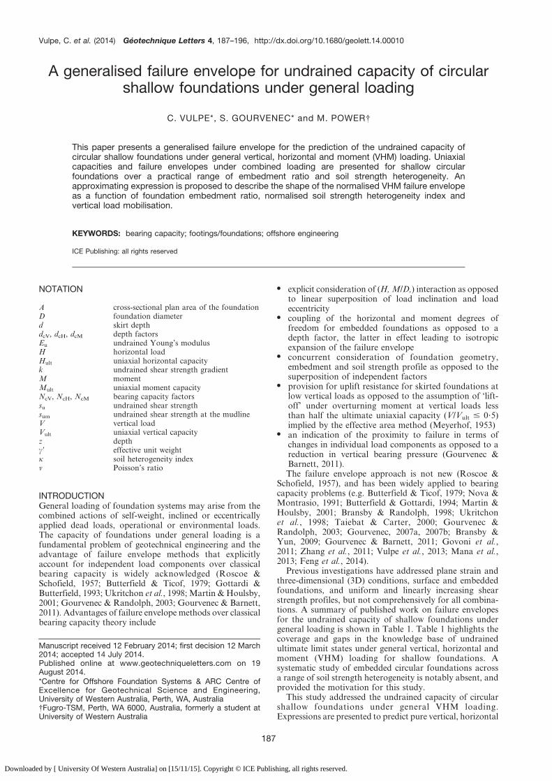
Model geometry and meshCircular foundations with embedment depth to diameterratios d/D of 0 (surface), 0?10, 0?25 and 0?50 wereconsidered. The foundations were wished-in-place (i.e. theinstallation process was not modelled). Zero-displacementboundaries of the mesh were located at a distance of 5D toeither side of the foundation centreline and 5D below thefree surface, sufficiently remote that the results wereindependent of the boundaries. Due to symmetry of thegeometry and planar loading conditions, a semi-cylindricalsection was modelled to optimise calculation efficiency. Anexample of the finite-element mesh used is shown in Fig. 1.
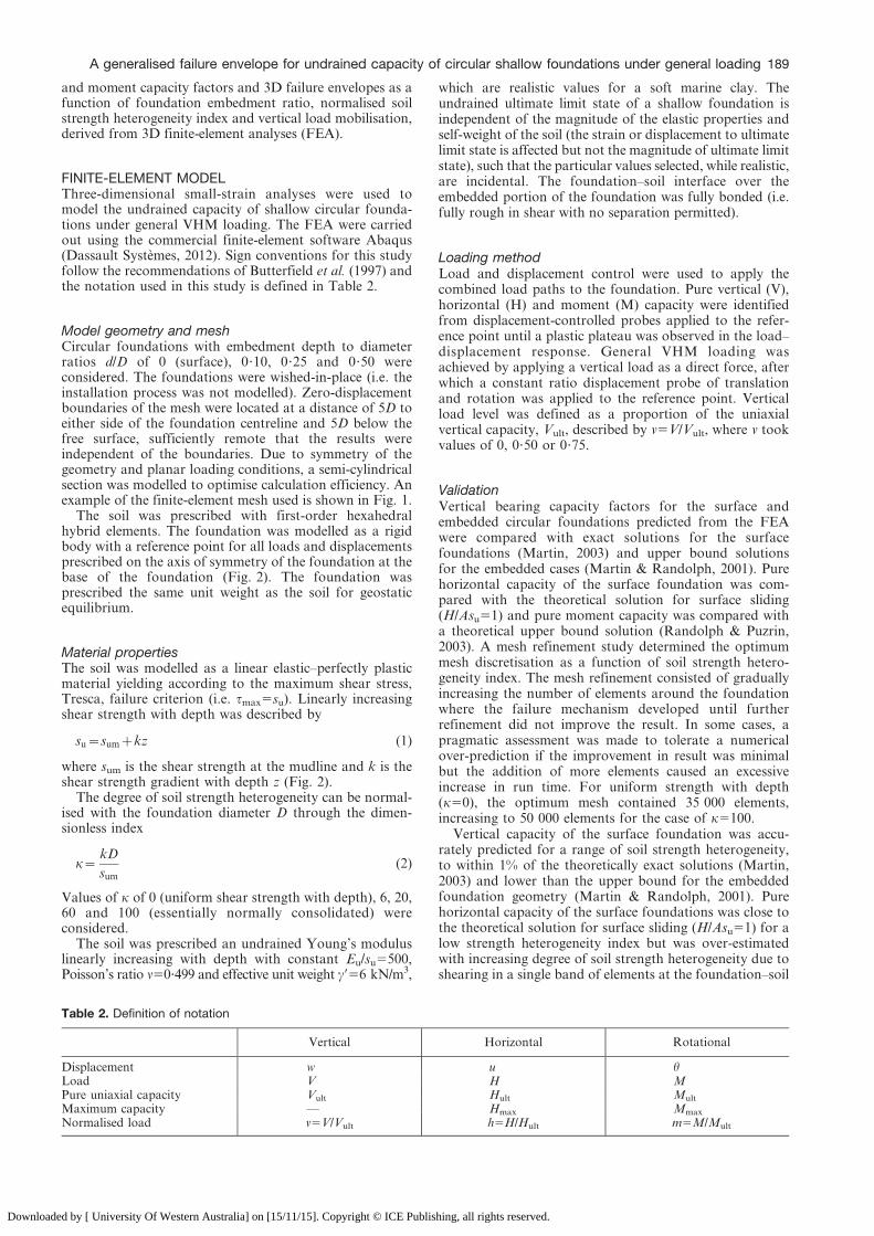
The soil was prescribed with first-order hexahedralhybrid elements. The foundation was modelled as a rigidbody with a reference point for all loads and displacementsprescribed on the axis of symmetry of the foundation at thebase of the foundation (Fig. 2). The foundation wasprescribed the same unit weight as the soil for geostaticequilibrium.
Material propertiesThe soil was modelled as a linear elastic–perfectly plasticmaterial yielding according to the maximum shear stress,Tresca, failure criterion (i.e. tmax5su). Linearly increasingshear strength with depth was described by
su~sumzkz (1)
where sum is the shear strength at the mudline and k is theshear strength gradient with depth z (Fig. 2).
The degree of soil strength heterogeneity can be normal-ised with the foundation diameter D through the dimen-sionless index
k~kD
sum
(2)
Values of k of 0 (uniform shear strength with depth), 6, 20,60 and 100 (essentially normally consolidated) wereconsidered.
The soil was prescribed an undrained Young’s moduluslinearly increasing with depth with constant Eu/su5500,Poisson’s ratio n50?499 and effective unit weight c956 kN/m3,
which are realistic values for a soft marine clay. Theundrained ultimate limit state of a shallow foundation isindependent of the magnitude of the elastic properties andself-weight of the soil (the strain or displacement to ultimatelimit state is affected but not the magnitude of ultimate limitstate), such that the particular values selected, while realistic,are incidental. The foundation–soil interface over theembedded portion of the foundation was fully bonded (i.e.fully rough in shear with no separation permitted).
Loading methodLoad and displacement control were used to apply thecombined load paths to the foundation. Pure vertical (V),horizontal (H) and moment (M) capacity were identifiedfrom displacement-controlled probes applied to the refer-ence point until a plastic plateau was observed in the load–displacement response. General VHM loading wasachieved by applying a vertical load as a direct force, afterwhich a constant ratio displacement probe of translationand rotation was applied to the reference point. Verticalload level was defined as a proportion of the uniaxialvertical capacity, Vult, described by v5V/Vult, where v tookvalues of 0, 0?50 or 0?75.
ValidationVertical bearing capacity factors for the surface andembedded circular foundations predicted from the FEAwere compared with exact solutions for the surfacefoundations (Martin, 2003) and upper bound solutionsfor the embedded cases (Martin & Randolph, 2001). Purehorizontal capacity of the surface foundation was com-pared with the theoretical solution for surface sliding(H/Asu51) and pure moment capacity was compared witha theoretical upper bound solution (Randolph & Puzrin,2003). A mesh refinement study determined the optimummesh discretisation as a function of soil strength hetero-geneity index. The mesh refinement consisted of graduallyincreasing the number of elements around the foundationwhere the failure mechanism developed until furtherrefinement did not improve the result. In some cases, apragmatic assessment was made to tolerate a numericalover-prediction if the improvement in result was minimalbut the addition of more elements caused an excessiveincrease in run time. For uniform strength with depth(k50), the optimum mesh contained 35 000 elements,increasing to 50 000 elements for the case of k5100.
Vertical capacity of the surface foundation was accu-rately predicted for a range of soil strength heterogeneity,to within 1% of the theoretically exact solutions (Martin,2003) and lower than the upper bound for the embeddedfoundation geometry (Martin & Randolph, 2001). Purehorizontal capacity of the surface foundations was close tothe theoretical solution for surface sliding (H/Asu51) for alow strength heterogeneity index but was over-estimatedwith increasing degree of soil strength heterogeneity due toshearing in a single band of elements at the foundation–soil
Table 2. Definition of notation
Vertical Horizontal Rotational
Displacement w u hLoad V H MPure uniaxial capacity Vult Hult Mult
Maximum capacity — Hmax Mmax
Normalised load v5V/Vult h5H/Hult m5M/Mult
A generalised failure envelope for undrained capacity of circular shallow foundations under general loading 189
Downloaded by [ University Of Western Australia] on [15/11/15]. Copyright © ICE Publishing, all rights reserved.
interface (up to 10% for k5100). Moment capacity wasslightly over-predicted compared with a theoretical upperbound solution (Randolph & Puzrin, 2003), by up to 10%,due to representation of a circular scoop failure mechanismwith hexahedral elements.
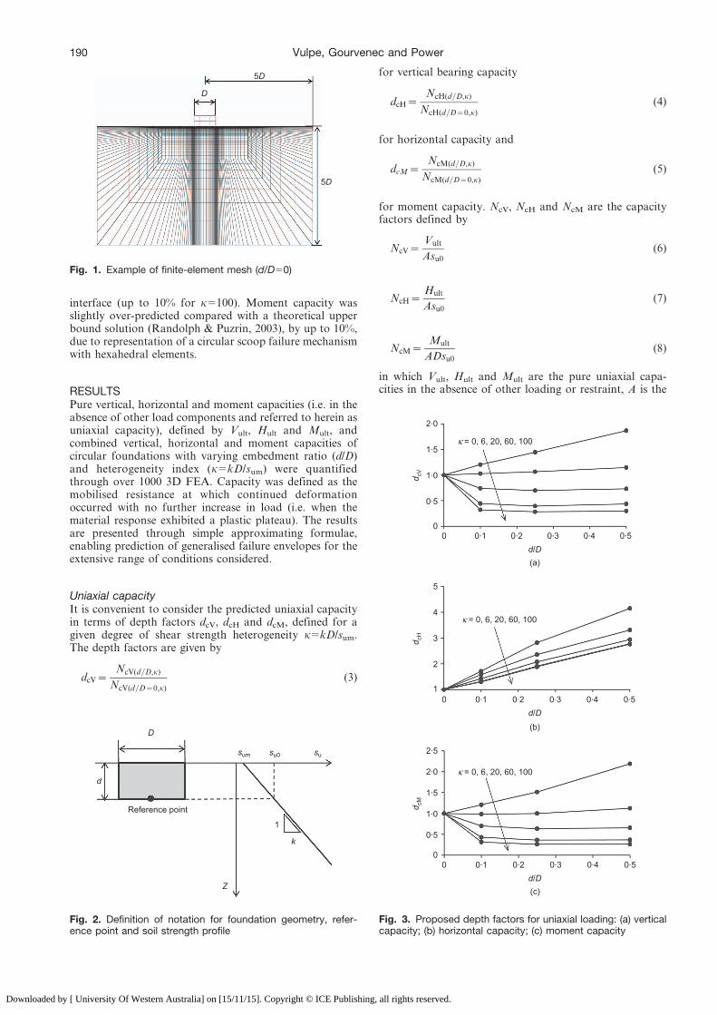
RESULTSPure vertical, horizontal and moment capacities (i.e. in theabsence of other load components and referred to herein asuniaxial capacity), defined by Vult, Hult and Mult, andcombined vertical, horizontal and moment capacities ofcircular foundations with varying embedment ratio (d/D)and heterogeneity index (k5kD/sum) were quantifiedthrough over 1000 3D FEA. Capacity was defined as themobilised resistance at which continued deformationoccurred with no further increase in load (i.e. when thematerial response exhibited a plastic plateau). The resultsare presented through simple approximating formulae,enabling prediction of generalised failure envelopes for theextensive range of conditions considered.
Uniaxial capacityIt is convenient to consider the predicted uniaxial capacityin terms of depth factors dcV, dcH and dcM, defined for agiven degree of shear strength heterogeneity k5kD/sum.The depth factors are given by
dcV~NcV(d=D,k)
NcV(d=D~0,k)
(3)
for vertical bearing capacity
dcH~NcH(d=D,k)
NcH(d=D~0,k)
(4)
for horizontal capacity and
dcM~NcM(d=D,k)
NcM(d=D~0,k)
(5)
for moment capacity. NcV, NcH and NcM are the capacityfactors defined by
NcV~Vult
Asu0
(6)
NcH~Hult
Asu0
(7)
NcM~Mult
ADsu0
(8)
in which Vult, Hult and Mult are the pure uniaxial capa-cities in the absence of other loading or restraint, A is the
5D
5D
D
Fig. 1. Example of finite-element mesh (d/D50)
sum
Z
k
su0 su
D
Reference point
d
1
Fig. 2. Definition of notation for foundation geometry, refer-ence point and soil strength profile
1.5
1.0
0.5
d cV
d/D
2.0
00
(a)
(b)
(c)
0.40.30.20.1 0.5
κ = 0, 6, 20, 60, 100
1.5
1.0
0.5
d cM
d/D
2.0
2.5
00 0.40.30.20.1 0.5
κ = 0, 6, 20, 60, 100
4
3
2
d cH
d/D
5
10 0.40.30.20.1 0.5
κ = 0, 6, 20, 60, 100
Fig. 3. Proposed depth factors for uniaxial loading: (a) verticalcapacity; (b) horizontal capacity; (c) moment capacity
190 Vulpe, Gourvenec and Power
Downloaded by [ University Of Western Australia] on [15/11/15]. Copyright © ICE Publishing, all rights reserved.
cross-sectional plan area of the foundation, D is thefoundation diameter and su0 is the undrained shear strengthat foundation level, su05sum+kd.
The vertical bearing capacity factor NcV(d/D50,k) for asurface circular foundation (i.e. d/D50) can be defined as afunction of soil strength heterogeneity index k from
Table 3. Depth factors for uniaxial vertical, horizontal and moment capacity; dc5Nc(d/D,k)/Nc(d/D50,k)
d/D k5kD/sum dcV dcH dcM
0 0 1 1 10 6 1 1 10 20 1 1 10 60 1 1 10 100 1 1 10?10 0 1?20 1?72 1?210?10 6 1?03 1?58 0?980?10 20 0?74 1?42 0?700?10 60 0?44 1?32 0?430?10 100 0?32 1?30 0?320?25 0 1?45 2?82 1?510?25 6 1?06 2?36 1?000?25 20 0?70 2?07 0?630?25 60 0?40 1?91 0?360?25 100 0?28 1?89 0?260?50 0 1?87 4?15 2?190?50 6 1?15 3?31 1?130?50 20 0?73 2?94 0?660?50 60 0?44 2?78 0?370?50 100 0?30 2?76 0?27
Table 4. Uniaxial capacity factors
d/D k5kD/sum NcV NcH NcM
0 0 6?05 1 0?670 6 9?85 1 1?190 20 15?48 1 1?920 60 27?69 1 3?490 100 37?88 1 4?770?10 0 7?28 1?72 0?810?10 6 10?11 1?58 1?170?10 20 11?46 1?42 1?350?10 60 12?30 1?32 1?490?10 100 12?25 1?30 1?500?25 0 8?75 2?82 1?010?25 6 10?48 2?36 1?190?25 20 10?81 2?07 1?220?25 60 10?97 1?91 1?260?25 100 10?78 1?89 1?250?50 0 11?29 4?15 1?470?50 6 11?29 3?31 1?340?50 20 11?31 2?94 1?260?50 60 12?07 2?78 1?280?50 100 11?31 2?76 1?27
0.8
0.8
0.6
0.6
0.4
0.4
0.2
0.2
FEAConservative curve fit
1.0
1.00
0
v = V/ Vult
h =
H/ H
ult
0.8
0.8
0.6
0.6
0.4
0.4
0.2
0.2
1.0
1.00
0
v = V/ Vult
m =
M/ M
ult
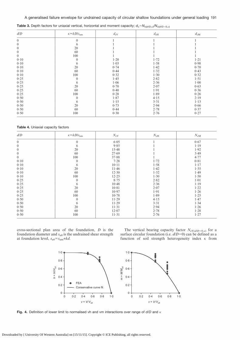
Fig. 4. Definition of lower limit to normalised vh and vm interactions over range of d/D and k
A generalised failure envelope for undrained capacity of circular shallow foundations under general loading 191
Downloaded by [ University Of Western Australia] on [15/11/15]. Copyright © ICE Publishing, all rights reserved.
available exact analytical solutions for a limited range of k(Houlsby & Wroth, 1983), from numerical solutions(Gourvenec & Mana, 2011) or with the numerical limitanalysis freeware ABC (Martin, 2003). The various sourcesresult in a similar relationship, which can be approximatedthrough
FV~NcV(d=D~0,k)
NcV(d=D~0,k~0)
~1z(0:09k)0:76 (9)
where NcV(d/D50,k50) 56?05, the exact solution for a roughcircular foundation on Tresca material (Cox et al., 1961).
NcH(d/D50,k) 51 irrespective of the soil heterogeneityindex since the pure horizontal load capacity of a surfacefoundation is governed by the mudline shear strength forcases of uniform or increasing shear strength with depth.
NcM(d/D50,k) can be defined as a function of soil strengthheterogeneity coefficient from the FEA solutions as
FM~NcM(d=D~0,k)
NcM(d=D~0,k~0)
~1z0:21k0:74 (10)
where NcM(d/D50,k50) 50?67, from an upper bound solution(Randolph & Puzrin, 2003).
The depth factors for pure vertical, horizontal andmoment capacity of circular foundations with embedmentratio 0 # d/D # 0?50 and soil shear strength heterogeneityindex 0 # k # 100 are shown in Fig. 3 and summarised inTable 3. Uniaxial capacity factors derived from Table 3and equations (3)–(10) are summarised in Table 4 to allowfor direct interpolation of uniaxial ultimate limit states Vult,Hult and Mult.
Combined vertical and horizontal load (VH) and verticalload and moment (VM) capacityUltimate limit states under combined vertical and hor-izontal load and vertical load and moment are shown inFig. 4 for the range of embedment ratios and soil strengthheterogeneity considered in normalised vh and vm space,where v5V/Vult, h5H/Hult and m5M/Mult. A power lawexpression is used to define a lower limit of normalised vhand vm interaction; that is, the FE results for allembedment ratios and degrees of soil strength heterogene-ity fall outside the fitted curve.
The normalised failure envelopes in vh space are closelybanded, irrespective of the foundation embedment ratio orthe soil shear strength heterogeneity index. The distributionof failure envelopes in normalised vm space is more diversebut shows no clear trend for grouping by embedment ratioor shear strength heterogeneity. Conservative fits to the vhand vm interactions are given by the power laws
h�~1{vq (11)
where q54?69 and
m�~1{vp (12)
in which p52?12.The expressions h* and m* are functions used to describe
the interactions in vh and vm space and determine thelimiting horizontal or moment load in conjunction with aknown applied vertical load. Inference of displacements atfailure through the principle of normality should not beapplied to the bounding surfaces described by equations (11)and (12) since they simply represent a lower limit to a rangeof observed results for a range of boundary conditions,rather than the precise shape of a particular failure envelopefor a given set of boundary conditions. A failure envelopeobserving normality would be expected to exhibit zerochange of gradient across the H 5 0 or M50 axes.
Vertical, horizontal and moment (VHM) capacityFailure envelopes were constructed in HM load space byinterpolating between individual HD/M load paths resulting
Constant displacement ratio probe
Envelope
1.5
1.5
0.5
0.5
1.0
1.0
–1.0 –0.5–1.5 00
H/ Asu0
M/ A
Ds u
0
Fig. 5. Example of failure envelope using probe tests from FEA(d/D50, k56, V50)
0
(a)
(b)
(c)
2 64–2–6 –4
M/ A
Ds u
0
d/ D = 0.50, 0.25, 0.10, 0v = 0.50κ = 0
1.5
2.5
2.0
0.5
1.0
0
H/ Asu0
0 2 64–2–6 –4
M/ A
Ds u
0
κ = 0, 6, 20, 60, 100d/D = 0.50 v = 0.50
1.5
2.5
2.0
0.5
1.0
0
H/ Asu0
0 1 32–1–3 –2
M/ A
Ds u
0v = 0, 0.50, 0.75d/D = 0.25
κ = 201.5
2.0
0.5
1.0
0
H/ Asu0
Fig. 6. Effect on shape and size of VHM failure envelopes ofvarying (a) foundation embedment ratio d/D, (b) soil strengthheterogeneity index, k5kD/sum and (c) vertical load mobilisationv5V/Vult
192 Vulpe, Gourvenec and Power
Downloaded by [ University Of Western Australia] on [15/11/15]. Copyright © ICE Publishing, all rights reserved.
1.4d/D = 0.50
m/m
*
h/h*
d/D = 0.10κ = 0
d/D = 0.50
m/m
*
d/D = 0κ = 100
1.2
1.0
1.0 1.5
0.8
0.6
0.4
0.2
–0.5 0.5–1.0
1.6
0
1.4
1.2
1.0
0.8
0.6
0.4
0.2
00
h/h*
v =0, 0.50, 0.75
1.0 1.5–0.5 0.5–1.0 0
Fig. 7. Comparison of selected failure envelopes predicted by FEA (broken lines) and approximating expression (solid lines)(equation (13)); applicable to all levels of vertical load mobilisation V/Vult
Table 5. Fitting parameters for approximating expression for VHM envelope for vertical load mobilisation 0 # V/Vult # 1
ka b
d/D d/D
0 0?10 0?25 0?50 0 0?10 0?25 0?50
0 1?63 1?93 2?16 1?61 20?05 20?16 20?44 20?606 2?00 1?85 1?94 1?76 0?06 20?10 20?27 20?55
20 2?46 2?09 1?90 1?99 20?01 20?02 20?21 20?4860 2?89 2?12 1?99 2?02 0?13 0?02 20?24 20?46
100 3?12 2?05 2?00 1?65 0?13 0?00 20?22 20?48
Table 6. Values of hmax/h* for vertical load mobilisation 0 # V/Vult # 1
d/Dk
0 6 20 60 100
0 1 1 1 1 10?10 1 1 1 1 10?25 1?09 1?02 1?01 1 10?50 1?35 1?15 1?13 1?11 1?11
Table 7. Fitting parameters for approximating expression for VHM envelope for limited vertical load mobilisation V/Vult # 0?50
ka b
d/D d/D
0 0?10 0?25 0?50 0 0?10 0?25 0?50
0 2?13 2?33 2?33 1?46 20?26 20?28 20?49 20?576 2?58 2?09 2?10 1?76 20?11 20?23 20?35 20?55
20 2?83 2?47 2?01 1?83 20?03 20?15 20?29 20?5560 3?32 2?51 2?10 2?19 0?04 20?13 20?29 20?51
100 3?74 2?56 2?12 1?90 0?08 20?12 20?27 20?48
Table 8. Maximum values of hmax/h* for low vertical load mobilisation V/Vult # 0?50
d/Dk
0 6 20 60 100
0 1 1 1 1 10?10 1?01 1 1 1 10?25 1?09 1?01 1?01 1 10?50 1?34 1?15 1?11 1?10 1?10
A generalised failure envelope for undrained capacity of circular shallow foundations under general loading 193
Downloaded by [ University Of Western Australia] on [15/11/15]. Copyright © ICE Publishing, all rights reserved.
from constant ratio displacement probes (u/Dh), as illu-strated in Fig. 5. Once the failure envelope is reached, eachload path travels around the envelope until it reaches a pointwhere the normal to the failure envelope corresponds to theprescribed displacement ratio.
Figure 6 shows two dimensional slices in the HM planethrough 3D VHM failure envelopes in dimensionless loadspace (H/Asu0, M/ADsu0) at discrete levels of vertical loadmobilisation v5V/Vult. The failure envelopes in HM load spaceare seen to be asymmetrical about the H and M axes. Thedegree of asymmetry depends on the load combination,foundation embedment ratio and soil strength heterogeneityand has been observed both experimentally (Gottardi et al.,1999; Martin & Houlsby, 2000; Zhang et al., 2014) andnumerically (Ukritchon et al., 1998; Bransby & Randolph,1999; Martin & Houlsby, 2001; Gourvenec & Randolph, 2003;Gourvenec, 2008; Bransby & Yun, 2009; Zhang et al., 2011).
The selections of FEA results presented in Fig. 6 demon-strate the effect on the size and shape of the failure envelopeswith varying foundation embedment ratio (Fig. 6(a)), soilshear strength heterogeneity coefficient (Fig. 6(b)) and relativevertical load level (Fig. 6(c)). The results shown in Fig. 5 areconsistent with the 60 sections of HM envelopes generatedacross the full range of foundation and soil conditionsconsidered and are selected to illustrate the observed trends,avoiding the clutter of presentation of all results.
Embedment ratio and soil strength heterogeneity have thegreatest influence on the shape of the failure envelopes(Figs 6(a) and 6(b), while the influence of the level of verticalload mobilisation is secondary (Fig. 6(c)). Increasing oblique-ness of the failure envelopes (due to HM cross-coupling) isassociated with increasing embedment ratio while asymmetryabout the moment axis is associated with reducing soil strengthheterogeneity. The level of vertical load has, by comparison,only secondary effects on the shape of the failure envelopes.
APPROXIMATING EXPRESSIONAn approximating expression to predict the shape of thenormalised VHM failure envelopes as a function offoundation embedment ratio and soil strength heterogene-ity index can be defined by the elliptical expression
h
h�
��������
� �a
zm
m�
� �a
z2bhm
h�m�~1 (13)
in which h5H/Hult and m5M/Mult define the normalisedhorizontal load and moment mobilisation, while the effect
of vertical mobilisation, v5V/Vult, is taken into accountthrough h* and m* (equations (11) and (12)). a and b arefitting parameters that depend on the foundation embed-ment ratio and soil shear strength heterogeneity index. Inthis case, the effect of the level of vertical load mobilisationis neglected in the prediction of the shape of the failureenvelope (since the influence is considered secondary), butis incorporated in the prediction of the size of the failureenvelope through h* and m*. The form of equation (13)was proposed by Gourvenec & Barnett (2011) for embeddedstrip foundations, but was defined as a function ofembedment ratio only, since only low values of soil strengthheterogeneity were considered in that case (k # 6) andtherefore the effect was limited.
Figure 7 compares FEA results with the approximatingexpression in normalised h*m* space for selected values ofthe foundation embedment ratio and soil strength hetero-geneity index. The FEA capture the changing shape of thefailure envelopes.
The fitting parameters a and b are listed in Table 5.Fitting parameters can be interpolated for intermediatevalues of the foundation embedment ratio and shearstrength heterogeneity index. The values of hmax/h* (hmax
represents the maximum horizontal mobilisation as a resultof HM cross-coupling) required to reconstruct the failureenvelopes are given in Table 6.
The results presented in Fig. 7 indicate that theapproximating expression becomes increasingly conserva-tive for low vertical mobilisation v5V/Vult by neglecting theeffect of vertical load level, but captures changes in shapeassociated with the foundation embedment ratio and soilstrength heterogeneity. It should be borne in mind thatpredictions of ultimate limit states under combined loading
1.4grey full range v black v ≤ 0.50
m/m
*
h/h*
κ = 0
1.2
1.0
1.0 1.5
0.8
0.6
0.4
0.2
–0.5 0.5–1.0
1.6
00
d/D = 0.50, 0.25, 0.10, 0
Fig. 8. Effect of vertical load mobilisation on available com-bined load capacity for full range of v (grey lines) and v,0?50(black lines)
3
α
d/D
β
2
1
00
(b)
d/D(a)
0.1 0.40.3
0 ≤ V/Vult ≤ 1
0 ≤ V/Vult ≤ 0.50
0.2 0.5
0 0.1 0.40.30.2 0.5
4
–1
3
α
β
2
1
0
4
–1
Fig. 9. Simplified fitting parameters aav and bav (lines) andexact fitting parameters (symbols)
194 Vulpe, Gourvenec and Power
Downloaded by [ University Of Western Australia] on [15/11/15]. Copyright © ICE Publishing, all rights reserved.
from the approximating expression proposed here areconsiderably less conservative than the predictions result-ing from methods based on classical bearing capacitytheory (demonstrated explicitly by Ukrtichon et al. (1998)and Gourvenec & Barnett (2011)), which forms the basis ofindustry design guidance worldwide.
For cases in which vertical loads are known to be wellbelow vertical capacity, optimised values of the fittingparameters a and b were derived for low values of verticalload mobilisation. Optimised fitting parameters for verticalload mobilisation v5V/Vult # 0?50 are presented inTable 7, with the necessary values of hmax/h* to reconstructthe envelopes given in Table 8. Figure 8 illustrates thepotential efficiency of accounting for limited vertical loadmobilisation, showing larger normalised failure envelopesfor the cases of limited vertical load mobilisation.
Simplified fitting parameters defined as a function ofonly the embedment ratio can be used to give a quick,rough indication of the failure envelope. For 0 # V/Vult # 1,representative fitting parameters may be given by
aav~2:28{1:03(d=D) (14a)
bav~0:05{1:15(d=D) (14b)
and for low vertical load mobilisation, V/Vult # 0?50, by
aav~2:55{1:43(d=D) (15a)
bav~{0:09{0:88(d=D) (15b)
Figures 9(a) and 9(b) show that a and b are closely bandedfor each embedment ratio, except for the surface case,irrespective of soil strength heterogeneity and that theaveraged expressions for aav and bav (equations (14) and(15)) provide a satisfactory fit.
The procedure for recreating a failure envelope for agiven foundation embedment ratio, soil strength hetero-geneity index and vertical load mobilisation based on themethod proposed in this paper is outlined in Table 9.
CONCLUDING REMARKSThis paper has presented undrained uniaxial ultimate limitstates and failure envelopes for the VHM capacity of shallowcircular foundations across a practical range of foundationembedment ratio and soil strength heterogeneity index. Theshape of the normalised failure envelope is shown to vary withfoundation embedment ratio and soil strength heterogeneity
index and, to a lesser extent, with the level of vertical loadmobilisation. A single algebraic expression was proposed toapproximate failure envelopes as a function of embedmentratio and soil strength heterogeneity index. Fitting parametersfor conditions of limited vertical load mobilisation were alsoproposed. Uniaxial bearing capacity factors were proposedthrough depth factors to transform normalised failureenvelopes to absolute load space.
The tabulated data and fitting expressions proposed inthe paper can be incorporated into a spreadsheet to
N enable automatic calculation of failure envelopes forselected foundation geometries and shear strength profiles
N optimise foundation geometry for a given set of designloads and shear strength profile
N evaluate load or material factors.
ACKNOWLEDGEMENTSThis work forms part of the activities of the Centre forOffshore Foundation Systems (COFS), currently supportedas a node of the Australian Research Council Centre ofExcellence for Geotechnical Science and Engineering. Thework presented in this paper is supported through ARCgrant (DP140100684), which is gratefully acknowledged.
REFERENCESBransby, M. F. & Randolph, M. F. (1998). Combined loading of
skirted foundations. Geotechnique 48, No. 5, 637–655.Bransby, M. F. & Randolph, M. F. (1999). The effect of embedment
depth on the undrained response of skirted foundations tocombined loading. Soils and Found. 39, No. 4, 19–33.
Bransby, M. F. & Yun, G. J. (2009). The undrained capacity ofskirted strip foundations under combined loading. Geotechnique59, No. 2, 115–125.
Butterfield, R. & Gottardi, G. (1994). A complete threedimensional failure envelope for shallow footings on sand.Geotechnique 44, No. 1, 181–184.
Butterfield, R. & Ticof, J. (1979). Design parameters for granularsoils (discussion contribution). Proc. 7th European Conf. SoilMech. and Foundation Engng (ECSMFE), Brighton, 4,259–261.
Butterfield, R., Houlsby, G. T. & Gottardi, G. (1997).Standardised sign conventions and notation for generallyloaded foundations. Geotechnique 47, No. 4, 1051–1052.
Cox, A. D., Eason, G. & Hopkins, H. G. (1961). Axiallysymmetric plastic deformation in soils. Proc. Royal Soc.London, Ser. A 254, 1–45.
Dassault Systemes (2012). Abaqus analysis user’s manual.Providence, RI: Simulia Corp.
Feng, X., Randolph, M. F., Gourvenec, S. & Wallerand, R.(2014). Design approach for rectangular mudmats under fullythree dimensional loading, Geotechnique 64, No. 1, 51–63.
Table 9. Summary of proposed procedure
Step Activity Reference
1 Evaluate d/D, su0 and kD/sum for given foundation geometry and soil strength profile2 Calculate Fv, dcV, NcV and Vult Equations (9), (3) and (6)3 Calculate vertical utilisation ratio v5V/Vult —4 Calculate h* and m* Equations (11) and (12)5 Choose exact fitting parameters a and b or calculate average fitting parameters aav
and bav
Tables 5 and 7, Equations (14) and (15)
6 Plot normalised h*m* envelope for given v (for constant intervals of h solve for m) —7 Calculate NcH and NcM (in absence of other loads or constraints) Equations (10), (4), (5), (7) and (8)8 Calculate H*/Asu0 and M*/ADsu0 at given vertical load level (i.e. h* and m*
multiplied by NcH and NcM, respectively)—
9 Convert h*m* envelope to dimensionless load space (i.e. h/(H*/Asu0) and m/(M*/ADsu0))
—
A generalised failure envelope for undrained capacity of circular shallow foundations under general loading 195
Downloaded by [ University Of Western Australia] on [15/11/15]. Copyright © ICE Publishing, all rights reserved.
Gottardi, G. & Butterfield, R. (1993). On the bearing capacity ofsurface footings on sand under general planar load. Soils andFound. 33, No. 3, 68–79.
Gottardi, G., Houlsby, G. T. & Butterfield, R. (1999). Plasticresponse of circular footings on sand under general planarloading. Geotechnique 49, No. 4, 453–469.
Gourvenec, S. (2007a). Failure envelopes for offshore shallowfoundations under general loading. Geotechnique 57, No. 3,715–728.
Gourvenec, S. (2007b). Shape effects on the capacity ofrectangular footings under general loading. Geotechnique 57,No. 8, 637–646.
Gourvenec, S. (2008). Effect of embedment on the undrainedcapacity of shallow foundations under general loading.Geotechnique 58, No. 3, 177–185.
Gourvenec, S. & Barnett, S. (2011). Undrained failure envelopefor skirted foundations under general loading. Geotechnique61, No. 3, 263–270.
Gourvenec, S. & Mana, D. K. S. (2011). Undrained vertical bearingcapacity factors for shallow foundations. Geotechnique Lett. 1,No. 4, 101–108.
Gourvenec, S. & Randolph, M. F. (2003). Effect of strength non-homogeneity on the shape and failure envelopes for combinedloading of strip and circular foundations on clay. Geotechnique53, No. 6, 575–586.
Govoni, L., Gourvenec, S. & Gottardi, G. (2011). A centrifugestudy on the effect of embedment on the drained response ofshallow foundations under combined loading. Geotechnique 61,No. 12, 1055–1068.
Houlsby, G. T. & Wroth, C. P. (1983). Calculation of stresses onshallow penetrometers and footings. Proc. IUTAM/IUGGSeabed Mechanics, Newcastle, 107–112.
Mana, D. K. S., Gourvenec, S. & Martin, C. M. (2013). Criticalskirt spacing for shallow foundations under general loading.ASCE J. Geotech. Geoenviron. Engng 139, No. 9, 1554–1566.
Martin, C. M. (2003). New software for rigorous bearing capacitycalculations. Proc. Br. Geotech. Assoc. Int. Conf. on Foundations,Dundee, 581–592.
Martin, C. M. & Houlsby, G. T. (2000). Combined loading ofspudcan foundations on clay: laboratory tests. Geotechnique50, No. 4, 325–338.
Martin, C. M. & Houlsby, G. T. (2001). Combined loading ofspudcan foundations on clay: numerical modelling. Geotechnique51, No. 8, 687–699.
Martin, C. M. & Randolph, M. F. (2001). Applications of thelower and upper bound theorems of plasticity to collapse ofcircular foundations. Proc. 10th Int. Conf. Int. Assoc. ofComputer Methods and Advances in Geomech (IACMAG),Tucson 2, 1417–1428.
Meyerhof, G. G. (1953). The bearing capacity of foundationsunder eccentric and inclined loads. Proc. 3rd Int. Conf. on SoilMechanics and Foundation Engng, Zurich, Switzerland, 1,440–445.
Nova, R. & Montrasio, L. (1991). Settlements of shallowfoundations on sand. Geotechnique 41, No. 2, 243–256.
Randolph, M. F. & Puzrin, A. M. (2003). Upper bound limitanalysis of circular foundations on clay under general loading.Geotechnique 53, No. 9, 785–796.
Roscoe, K. H. & Schofield, A. N. (1957). The stability of short pierfoundations in sand: discussion. Br. Weld. J., January, 12–18.
Taiebat, H. A. & Carter, J. P. (2000). Numerical studies of thebearing capacity of shallow foundations on cohesive soilsubjected to combined loading. Geotechnique 50, No. 4, 409–418.
Taiebat, H. A. & Carter, J. P. (2010). A failure surface for shallowcircular footings on cohesive soils. Geotechnique 60, No. 4,265–273.
Ukritchon, B., Whittle, A. J. & Sloan, S. W. (1998). Undrainedlimit analysis for combined loading of strip footings on clay.ASCE J. Geotech. Geoenviron. Engng 124, No. 3, 265–276.
Vulpe, C., Bienen, B. & Gaudin, C. (2013). Predicting theundrained capacity of skirted spudcans under combinedloading. Ocean Engng 74, 178–188.
Yun, G. & Bransby, M. F. (2007). The horizontal-momentcapacity of embedded foundations in undrained soil. Can.Geotech. J. 44, No. 4, 409–427.
Zhang, Y., Bienen, B., Cassidy, M.J. & Gourvenec, S. (2011). Theundrained bearing capacity of a spudcan foundation undercombined loading in soft clay. Marine Struct. 24, No. 4, 459–477.
Zhang, Y., Bienen, B., & Cassidy, M. J. (2014). A plasticity modelfor spudcan foundations in soft clay. Can. Geotech. J. 51, No.6, 629–646, http://dx.doi.org/10.1139/cgj-2013-0269.
WHAT DO YOU THINK?
To discuss this paper, please email up to 500 words tothe editor at [email protected]. Your contribution willbe forwarded to the author(s) for a reply and, ifconsidered appropriate by the editorial panel, will bepublished as a discussion.
196 Vulpe, Gourvenec and Power
Downloaded by [ University Of Western Australia] on [15/11/15]. Copyright © ICE Publishing, all rights reserved.