a design study in austempered ductile iron drive wheel … wheel.pdf · a design study in...
TRANSCRIPT

Title Page --Austempered Ductile Iron Casting
A Design Study in Austempered Ductile Iron
Drive Wheel for the Trackson a Compact Utility Loader
Design Study OutlineIntroductionDesign for Performance Austempered Ductile Iron Considerations Alloy Grade Selection Radii and FilletsDesign for Production Molding Method Cores versus Machining Riser DesignMachine and Heat TreatQuality AssuranceLessons Learned and Summary
Key Words = metal casting, austempered ductile iron, ADI, Smith Foundry, green sand Start the Design Study ! Next
Acknowledgment -- The metalcasting design studies are a joint effort of the
American Foundry Society and the Steel Founders' Society of America.Project funding was provided by the American Metalcasting Consortium Project, which
is sponsored by the Defense Logistics Agency, Attn: DLSC-T, Ft. Belvoir, VA, 22060-6221
AFS Home Page
Copyright 2005 by the American Foundry Society. All rights reserved. Address Comments to: [email protected]. Last Modified:May, 2005 by STG
In cooperation withSmith Foundry Co.
file:///C|/A-My%20Documents/My%20Webs/Drive%20Wheel/default.htm [5/25/05 5:03:37 PM]

Application
A Design Study in Austempered Ductile Iron - Smith Foundry Drive Wheel
Utility Loader -- ApplicationThe Toro Company produces the Dingo TX 400 compact utility loader,
designed for professional contractors working in tight quarters and difficult ground conditions.
The TX 400 series loaders are powered by 4-cycle gas engines and move on continuous rubber tracks, rather than on wheels.
● The walk-behind operator position provides 360 degrees of visibility and outstanding operator mobility.
● The continuous track drive on this models is a critical performance feature, providing excellent traction and floatation even in the most difficult ground conditions.
❍ Kevlar reinforcement of the track gives long life and durability under the most aggressive wear and abrasion conditions.
Back Next 2
AFS Home Page
Copyright 2005 by the American Foundry Society. All rights reserved. Address Comments to: [email protected]. Last Modified:April, 2005 by STG Page 1
In cooperation withSmith Foundry Co
file:///C|/A-My%20Documents/My%20Webs/Drive%20Wheel/dwheel_02.htm [5/25/05 5:03:44 PM]

Function
A Design Study in Austempered Ductile Iron - Smith Foundry Drive Wheel
Drive Wheel -- FunctionThe left and right rubber tracks on the Toro Dingo TX
413 utility loader are each driven by a metal drive wheel, 12" in diameter.
● The two drive wheels transfer power from the 13 Horsepower Honda 4-cycle engine to the tracks of the loader.
● The wheels have to handle high torque loads, impact, fatigue, abrasion, and corrosion in many different field conditions across a wide range of temperatures.
Back Next 3
AFS Home Page
Copyright 2005 by the American Foundry Society. All rights reserved. Address Comments to: [email protected]. Last Modified:May, 2005 by STG Page 1
In cooperation withSmith Foundry Co
file:///C|/A-My%20Documents/My%20Webs/Drive%20Wheel/dwheel_03.htm [5/25/05 5:03:49 PM]

Description
A Design Study in Austempered Ductile Iron - Smith Foundry Drive Wheel
Drive Wheel -- DescriptionThe drive wheel consists of a drive hub with two wheel rims connected to the hub by six heavy spokes. Eleven cross bars on the perimeter engage
with and drive the rubber tracks.
The wheel is 12" in outer diameter and 3.6" in height and has a weight of 23.5 pounds.The inner hub has a diameter of 3.65" inches and a height of 2.5" with a 1" center bore. The maximum wall thickness is 1.32" in the hub, while the nominal wall thickness is 0.5" in the rims and cross bars. The eleven cross bars on the OD are 0.7" in diameter.
Back Next 4
AFS Home Page
Copyright 2005 by the American Foundry Society. All rights reserved. Address Comments to: [email protected]. Last Modified:May, 2005 by STG Page 1
In cooperation withSmith Foundry Co
file:///C|/A-My%20Documents/My%20Webs/Drive%20Wheel/dwheel_04.htm [5/25/05 5:03:53 PM]
Requirements
A Design Study in Austempered Ductile Iron - Smith Foundry Drive Wheel
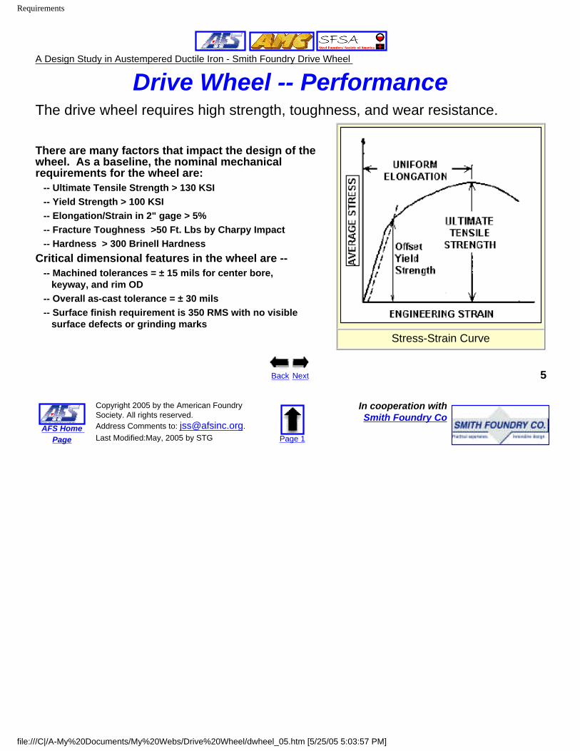
Drive Wheel -- PerformanceThe drive wheel requires high strength, toughness, and wear resistance.
There are many factors that impact the design of the wheel. As a baseline, the nominal mechanical requirements for the wheel are:
-- Ultimate Tensile Strength > 130 KSI-- Yield Strength > 100 KSI-- Elongation/Strain in 2" gage > 5%-- Fracture Toughness >50 Ft. Lbs by Charpy Impact-- Hardness > 300 Brinell Hardness
Critical dimensional features in the wheel are ---- Machined tolerances = ± 15 mils for center bore, keyway, and rim OD-- Overall as-cast tolerance = ± 30 mils-- Surface finish requirement is 350 RMS with no visible surface defects or grinding marks
Stress-Strain Curve
Back Next 5
AFS Home Page
Copyright 2005 by the American Foundry Society. All rights reserved. Address Comments to: [email protected]. Last Modified:May, 2005 by STG Page 1
In cooperation withSmith Foundry Co
file:///C|/A-My%20Documents/My%20Webs/Drive%20Wheel/dwheel_05.htm [5/25/05 5:03:57 PM]
Conversion
A Design Study in Austempered Ductile Iron - Smith Foundry Drive Wheel
Drive Wheel -- Design Approach
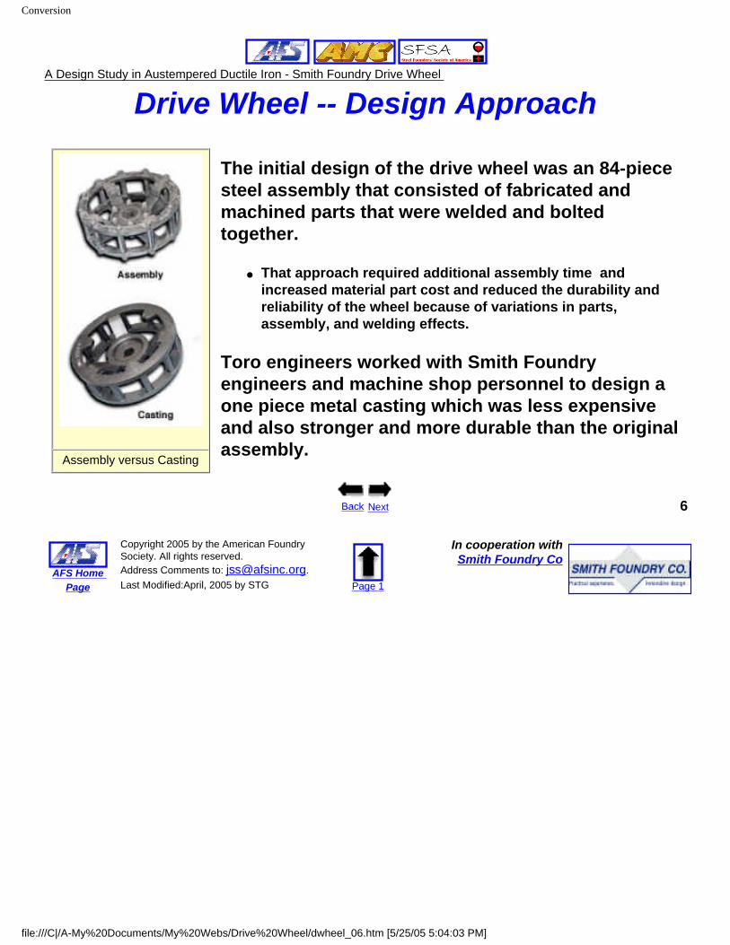
Assembly versus Casting
The initial design of the drive wheel was an 84-piece steel assembly that consisted of fabricated and machined parts that were welded and bolted together.
● That approach required additional assembly time and increased material part cost and reduced the durability and reliability of the wheel because of variations in parts, assembly, and welding effects.
Toro engineers worked with Smith Foundry engineers and machine shop personnel to design a one piece metal casting which was less expensive and also stronger and more durable than the original assembly.
Back Next 6
AFS Home Page
Copyright 2005 by the American Foundry Society. All rights reserved. Address Comments to: [email protected]. Last Modified:April, 2005 by STG Page 1
In cooperation withSmith Foundry Co
file:///C|/A-My%20Documents/My%20Webs/Drive%20Wheel/dwheel_06.htm [5/25/05 5:04:03 PM]
Austempered Ductile Iron
A Design Study in Austempered Ductile Iron - Smith Foundry Drive Wheel
Alloy SelectionThe mechanical requirements for the wheel first pointed to a conventional steel as the casting
alloy of choice.
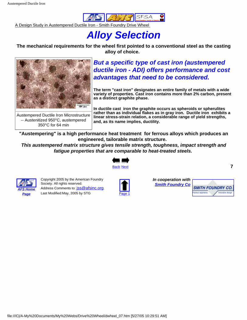
Austempered Ductile Iron Microstructure -- Austenitized 950°C, austempered
350°C for 64 min
But a specific type of cast iron (austempered ductile iron - ADI) offers performance and cost advantages that need to be considered.
The term "cast iron" designates an entire family of metals with a wide variety of properties. Cast iron contains more than 2% carbon, present as a distinct graphite phase.
In ductile cast iron the graphite occurs as spheroids or spherulites rather than as individual flakes as in gray iron. Ductile iron exhibits a linear stress-strain relation, a considerable range of yield strengths, and, as its name implies, ductility.
"Austempering" is a high performance heat treatment for ferrous alloys which produces an engineered, tailorable matrix structure.
This austempered matrix structure gives tensile strength, toughness, impact strength and fatigue properties that are comparable to heat-treated steels.
Back Next 7
AFS Home Page
Copyright 2005 by the American Foundry Society. All rights reserved. Address Comments to: [email protected]. Last Modified:May, 2005 by STG Page 1
In cooperation withSmith Foundry Co
file:///C|/A-My%20Documents/My%20Webs/Drive%20Wheel/dwheel_07.htm [5/27/05 10:29:51 AM]
ADI Cost Advantages
A Design Study in Austempered Ductile Iron - Smith Foundry Drive Wheel
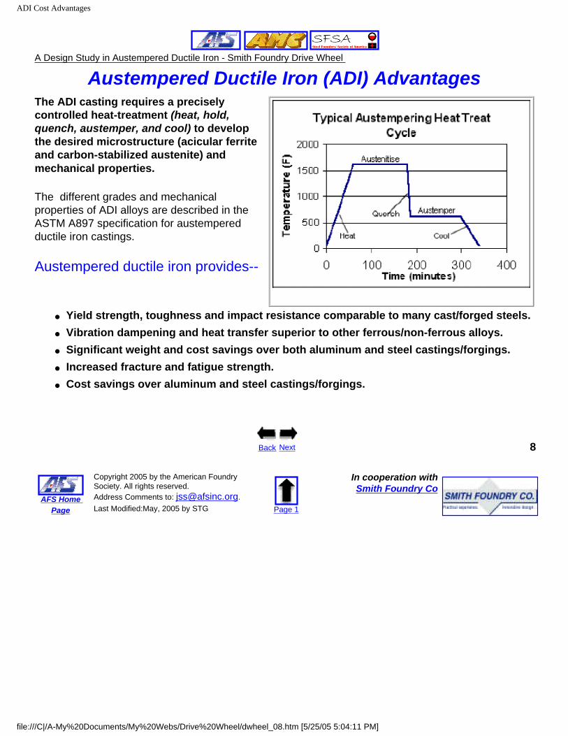
Austempered Ductile Iron (ADI) AdvantagesThe ADI casting requires a precisely controlled heat-treatment (heat, hold, quench, austemper, and cool) to develop the desired microstructure (acicular ferrite and carbon-stabilized austenite) and mechanical properties.
The different grades and mechanical properties of ADI alloys are described in the ASTM A897 specification for austempered ductile iron castings.
Austempered ductile iron provides--
● Yield strength, toughness and impact resistance comparable to many cast/forged steels.● Vibration dampening and heat transfer superior to other ferrous/non-ferrous alloys.● Significant weight and cost savings over both aluminum and steel castings/forgings.● Increased fracture and fatigue strength.● Cost savings over aluminum and steel castings/forgings.
Back Next 8
AFS Home Page
Copyright 2005 by the American Foundry Society. All rights reserved. Address Comments to: [email protected]. Last Modified:May, 2005 by STG Page 1
In cooperation withSmith Foundry Co
file:///C|/A-My%20Documents/My%20Webs/Drive%20Wheel/dwheel_08.htm [5/25/05 5:04:11 PM]
Design Issues
A Design Study in Austempered Ductile Iron - Smith Foundry Drive Wheel
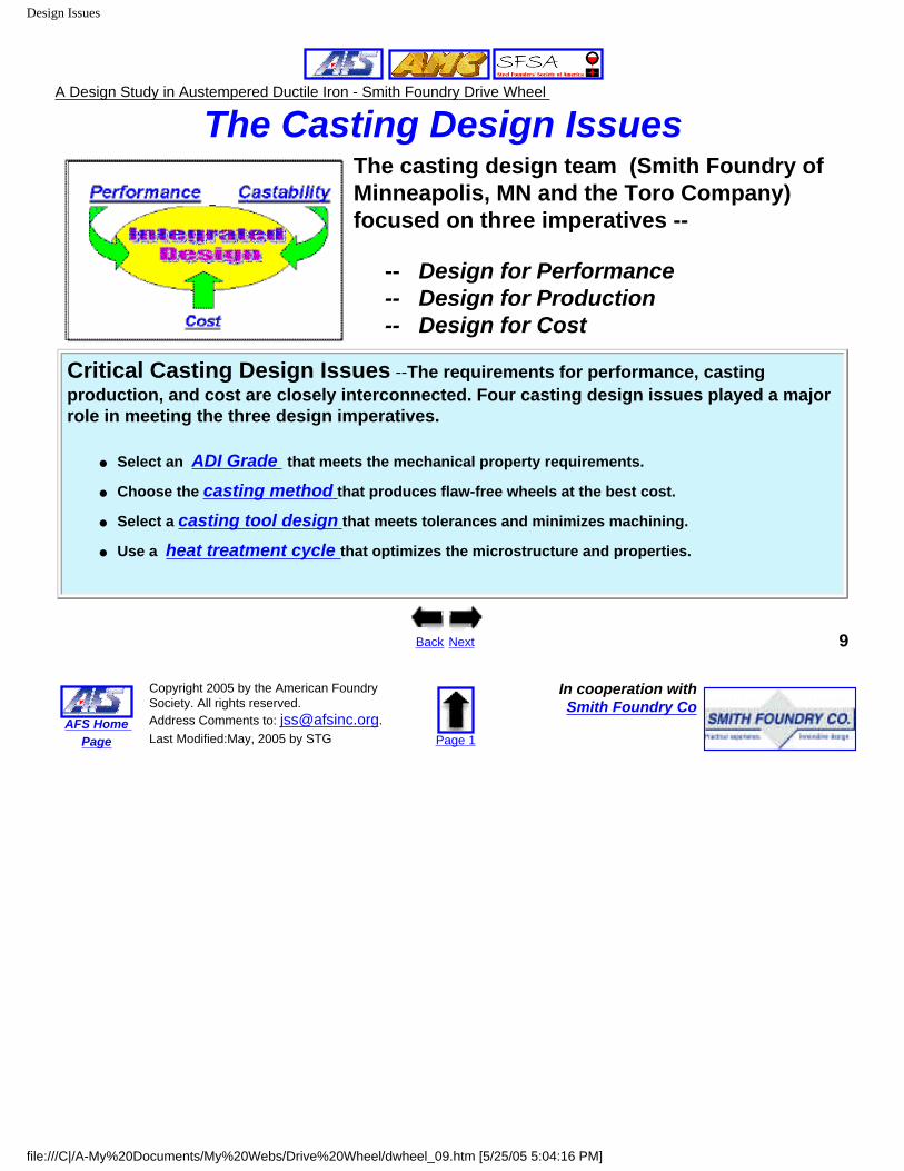
The Casting Design Issues The casting design team (Smith Foundry of Minneapolis, MN and the Toro Company) focused on three imperatives --
-- Design for Performance-- Design for Production-- Design for Cost
Critical Casting Design Issues --The requirements for performance, casting production, and cost are closely interconnected. Four casting design issues played a major role in meeting the three design imperatives.
● Select an ADI Grade that meets the mechanical property requirements.
● Choose the casting method that produces flaw-free wheels at the best cost.
● Select a casting tool design that meets tolerances and minimizes machining.
● Use a heat treatment cycle that optimizes the microstructure and properties.
Back Next 9
AFS Home Page
Copyright 2005 by the American Foundry Society. All rights reserved. Address Comments to: [email protected]. Last Modified:May, 2005 by STG Page 1
In cooperation withSmith Foundry Co
file:///C|/A-My%20Documents/My%20Webs/Drive%20Wheel/dwheel_09.htm [5/25/05 5:04:16 PM]
A-897 Selection
A Design Study in Austempered Ductile Iron - Smith Foundry Drive Wheel
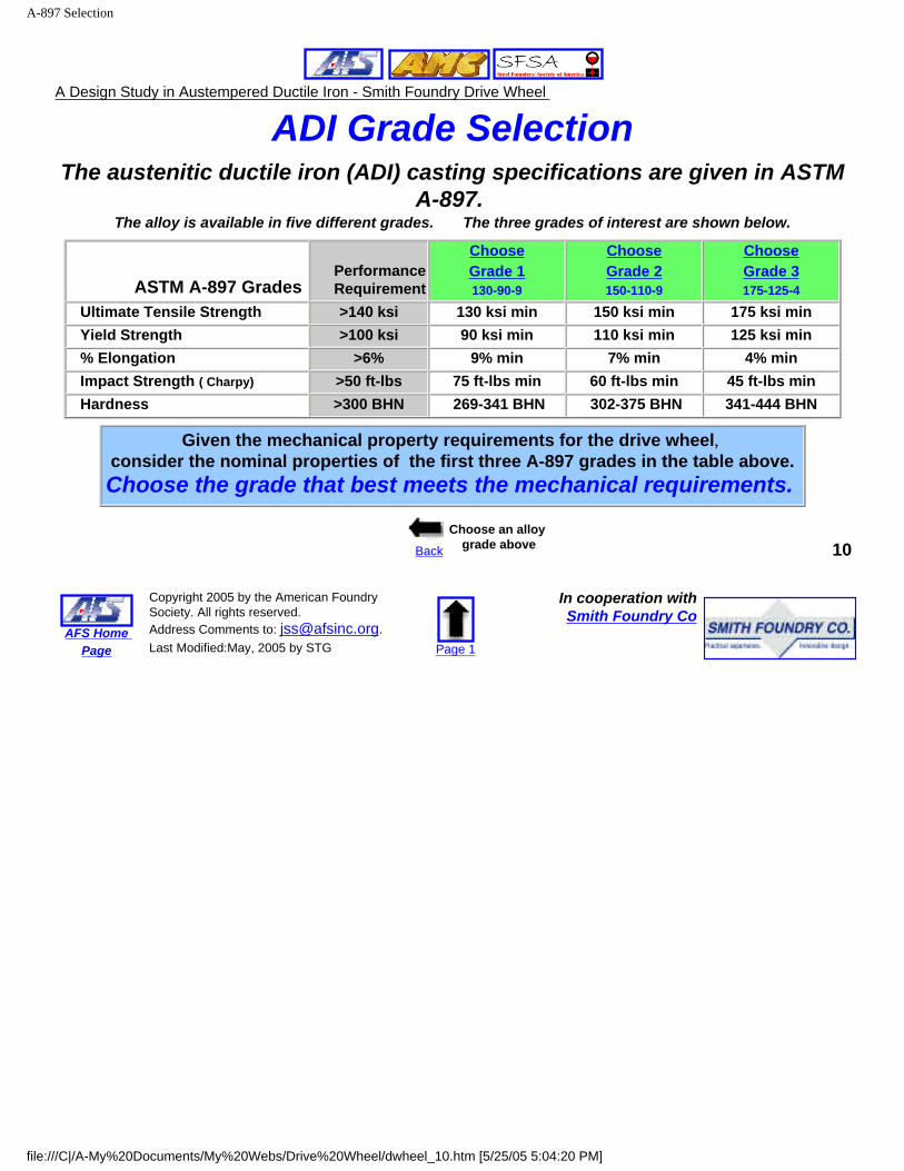
ADI Grade SelectionThe austenitic ductile iron (ADI) casting specifications are given in ASTM
A-897. The alloy is available in five different grades. The three grades of interest are shown below.
ASTM A-897 Grades PerformanceRequirement
ChooseGrade 1130-90-9
ChooseGrade 2150-110-9
ChooseGrade 3175-125-4
Ultimate Tensile Strength >140 ksi 130 ksi min 150 ksi min 175 ksi min Yield Strength >100 ksi 90 ksi min 110 ksi min 125 ksi min % Elongation >6% 9% min 7% min 4% min Impact Strength ( Charpy) >50 ft-lbs 75 ft-lbs min 60 ft-lbs min 45 ft-lbs min Hardness >300 BHN 269-341 BHN 302-375 BHN 341-444 BHN
Given the mechanical property requirements for the drive wheel, consider the nominal properties of the first three A-897 grades in the table above.Choose the grade that best meets the mechanical requirements.
Back
Choose an alloy grade above 10
AFS Home Page
Copyright 2005 by the American Foundry Society. All rights reserved. Address Comments to: [email protected]. Last Modified:May, 2005 by STG Page 1
In cooperation withSmith Foundry Co
file:///C|/A-My%20Documents/My%20Webs/Drive%20Wheel/dwheel_10.htm [5/25/05 5:04:20 PM]
A-897-Grade 1
A Design Study in Austempered Ductile Iron - Smith Foundry Drive Wheel
A-897 Grade 1The ASTM A-897 ductile iron casting specification is based on demonstrated mechanical
properties which depend on the proper cast iron microstructure.
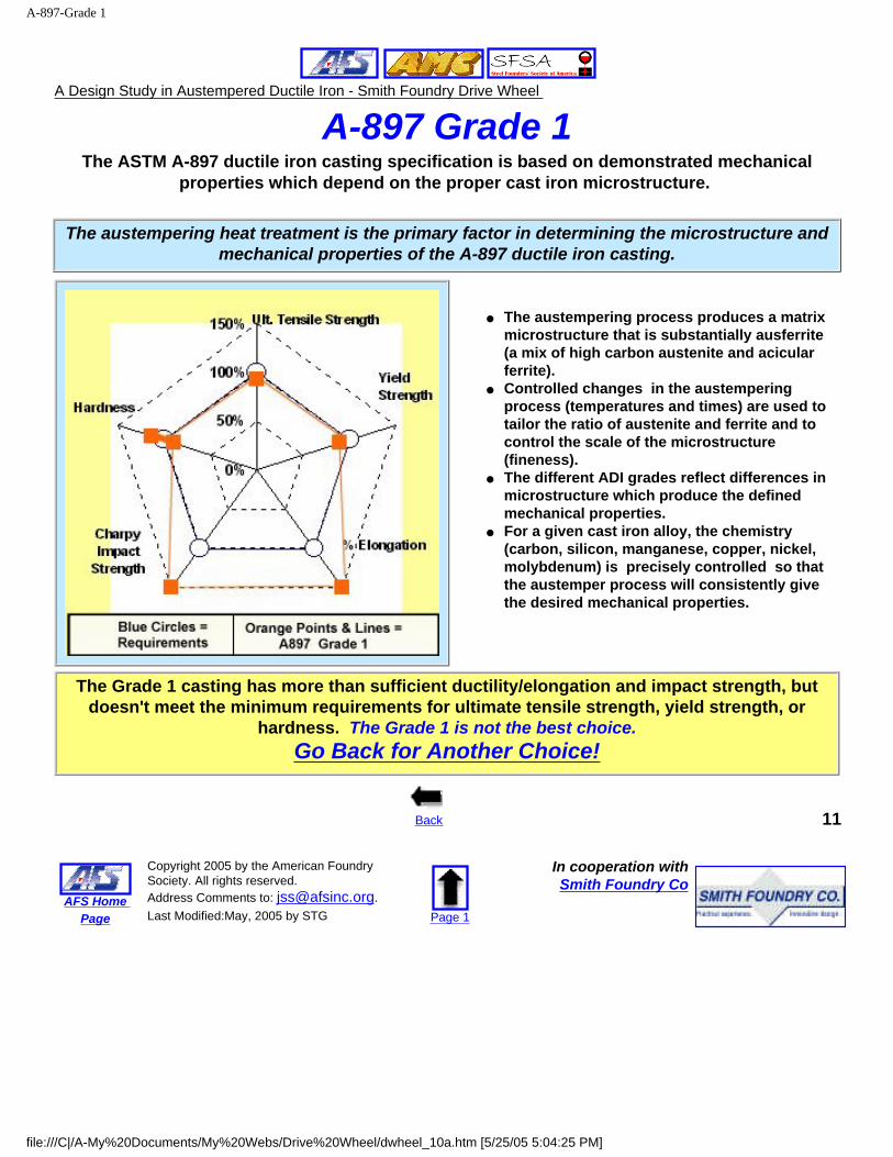
The austempering heat treatment is the primary factor in determining the microstructure and mechanical properties of the A-897 ductile iron casting.
● The austempering process produces a matrix microstructure that is substantially ausferrite (a mix of high carbon austenite and acicular ferrite).
● Controlled changes in the austempering process (temperatures and times) are used to tailor the ratio of austenite and ferrite and to control the scale of the microstructure (fineness).
● The different ADI grades reflect differences in microstructure which produce the defined mechanical properties.
● For a given cast iron alloy, the chemistry (carbon, silicon, manganese, copper, nickel, molybdenum) is precisely controlled so that the austemper process will consistently give the desired mechanical properties.
The Grade 1 casting has more than sufficient ductility/elongation and impact strength, but doesn't meet the minimum requirements for ultimate tensile strength, yield strength, or
hardness. The Grade 1 is not the best choice.Go Back for Another Choice!
Back 11
AFS Home Page
Copyright 2005 by the American Foundry Society. All rights reserved. Address Comments to: [email protected]. Last Modified:May, 2005 by STG Page 1
In cooperation withSmith Foundry Co
file:///C|/A-My%20Documents/My%20Webs/Drive%20Wheel/dwheel_10a.htm [5/25/05 5:04:25 PM]
A-897 Grade 2
A Design Study in Austempered Ductile Iron - Smith Foundry Drive Wheel
A-897 Grade 2The ASTM A-897 ductile iron casting specification is based on demonstrated mechanical
properties which depend on the proper cast iron microstructure.
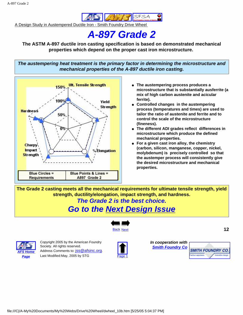
The austempering heat treatment is the primary factor in determining the microstructure and mechanical properties of the A-897 ductile iron casting.
● The austempering process produces a microstructure that is substantially ausferrite (a mix of high carbon austenite and acicular ferrite).
● Controlled changes in the austempering process (temperatures and times) are used to tailor the ratio of austenite and ferrite and to control the scale of the microstructure (fineness).
● The different ADI grades reflect differences in microstructure which produce the defined mechanical properties.
● For a given cast iron alloy, the chemistry (carbon, silicon, manganese, copper, nickel, molybdenum) is precisely controlled so that the austemper process will consistently give the desired microstructure and mechanical properties.
The Grade 2 casting meets all the mechanical requirements for ultimate tensile strength, yield strength, ductility/elongation, impact strength, and hardness.
The Grade 2 is the best choice.Go to the Next Design Issue
Back Next 12
AFS Home Page
Copyright 2005 by the American Foundry Society. All rights reserved. Address Comments to: [email protected]. Last Modified:May, 2005 by STG Page 1
In cooperation withSmith Foundry Co
file:///C|/A-My%20Documents/My%20Webs/Drive%20Wheel/dwheel_10b.htm [5/25/05 5:04:37 PM]
A-897 Grade 3
A Design Study in Austempered Ductile Iron - Smith Foundry Drive Wheel
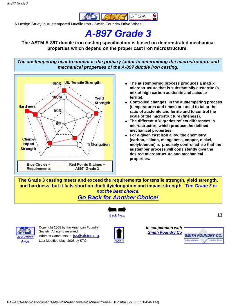
A-897 Grade 3The ASTM A-897 ductile iron casting specification is based on demonstrated mechanical
properties which depend on the proper cast iron microstructure.
The austempering heat treatment is the primary factor in determining the microstructure and mechanical properties of the A-897 ductile iron casting.
● The austempering process produces a matrix microstructure that is substantially ausferrite (a mix of high carbon austenite and acicular ferrite).
● Controlled changes in the austempering process (temperatures and times) are used to tailor the ratio of austenite and ferrite and to control the scale of the microstructure (fineness).
● The different ADI grades reflect differences in microstructure which produce the defined mechanical properties..
● For a given cast iron alloy, the chemistry (carbon, silicon, manganese, copper, nickel, molybdenum) is precisely controlled so that the austemper process will consistently give the desired microstructure and mechanical properties.
The Grade 3 casting meets and exceed the requirements for tensile strength, yield strength, and hardness, but it falls short on ductility/elongation and impact strength. The Grade 3 is
not the best choice.Go Back for Another Choice!
Back Next 13
AFS Home Page
Copyright 2005 by the American Foundry Society. All rights reserved. Address Comments to: [email protected]. Last Modified:May, 2005 by STG Page 1
In cooperation withSmith Foundry Co
file:///C|/A-My%20Documents/My%20Webs/Drive%20Wheel/dwheel_10c.htm [5/25/05 5:04:46 PM]
Stress Reduction - Fillets and Radii
A Design Study in Austempered Ductile Iron - Smith Foundry Drive Wheel
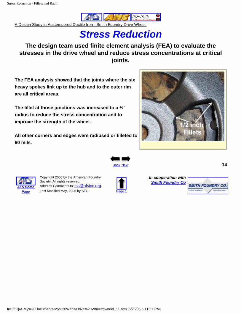
Stress ReductionThe design team used finite element analysis (FEA) to evaluate the
stresses in the drive wheel and reduce stress concentrations at critical joints.
The FEA analysis showed that the joints where the six heavy spokes link up to the hub and to the outer rim are all critical areas.
The fillet at those junctions was increased to a ½" radius to reduce the stress concentration and to improve the strength of the wheel.
All other corners and edges were radiused or filleted to 60 mils.
Back Next 14
AFS Home Page
Copyright 2005 by the American Foundry Society. All rights reserved. Address Comments to: [email protected]. Last Modified:May, 2005 by STG Page 1
In cooperation withSmith Foundry Co
file:///C|/A-My%20Documents/My%20Webs/Drive%20Wheel/dwheel_11.htm [5/25/05 5:11:57 PM]
Sand Molding
A Design Study in Austempered Ductile Iron - Smith Foundry Drive Wheel
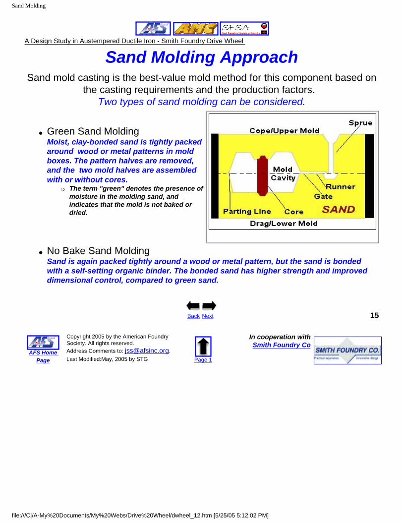
Sand Molding ApproachSand mold casting is the best-value mold method for this component based on
the casting requirements and the production factors. Two types of sand molding can be considered.
● Green Sand Molding Moist, clay-bonded sand is tightly packed around wood or metal patterns in mold boxes. The pattern halves are removed, and the two mold halves are assembled with or without cores.
❍ The term "green" denotes the presence of moisture in the molding sand, and indicates that the mold is not baked or dried.
● No Bake Sand MoldingSand is again packed tightly around a wood or metal pattern, but the sand is bonded with a self-setting organic binder. The bonded sand has higher strength and improved dimensional control, compared to green sand.
Back Next 15
AFS Home Page
Copyright 2005 by the American Foundry Society. All rights reserved. Address Comments to: [email protected]. Last Modified:May, 2005 by STG Page 1
In cooperation withSmith Foundry Co
file:///C|/A-My%20Documents/My%20Webs/Drive%20Wheel/dwheel_12.htm [5/25/05 5:12:02 PM]
Mold Selection
A Design Study in Austempered Ductile Iron - Smith Foundry Drive Wheel
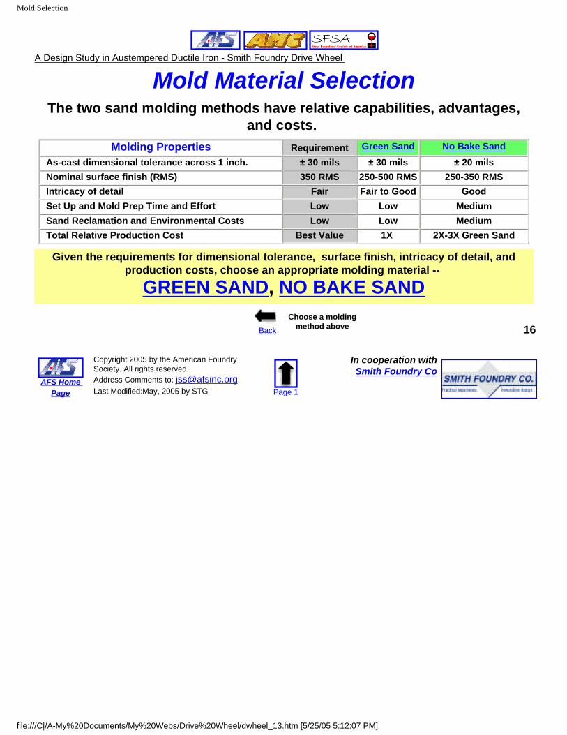
Mold Material SelectionThe two sand molding methods have relative capabilities, advantages,
and costs. Molding Properties Requirement Green Sand No Bake Sand
As-cast dimensional tolerance across 1 inch. ± 30 mils ± 30 mils ± 20 mils Nominal surface finish (RMS) 350 RMS 250-500 RMS 250-350 RMS Intricacy of detail Fair Fair to Good Good Set Up and Mold Prep Time and Effort Low Low Medium Sand Reclamation and Environmental Costs Low Low Medium Total Relative Production Cost Best Value 1X 2X-3X Green Sand
Given the requirements for dimensional tolerance, surface finish, intricacy of detail, and production costs, choose an appropriate molding material --
GREEN SAND, NO BAKE SAND
Back
Choose a molding method above 16
AFS Home Page
Copyright 2005 by the American Foundry Society. All rights reserved. Address Comments to: [email protected]. Last Modified:May, 2005 by STG Page 1
In cooperation withSmith Foundry Co
file:///C|/A-My%20Documents/My%20Webs/Drive%20Wheel/dwheel_13.htm [5/25/05 5:12:07 PM]
Green Sand
A Design Study in Austempered Ductile Iron - Smith Foundry Drive Wheel
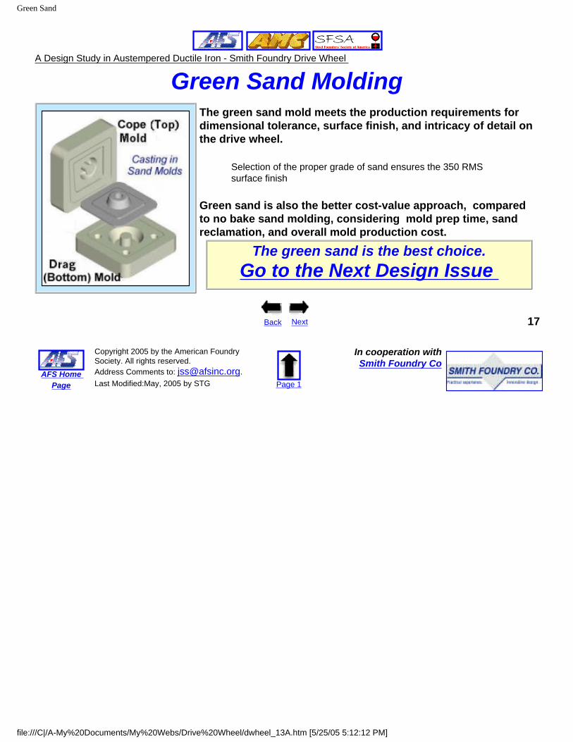
Green Sand Molding
The green sand mold meets the production requirements for dimensional tolerance, surface finish, and intricacy of detail on the drive wheel.
Selection of the proper grade of sand ensures the 350 RMS surface finish
Green sand is also the better cost-value approach, compared to no bake sand molding, considering mold prep time, sand reclamation, and overall mold production cost.
The green sand is the best choice.Go to the Next Design Issue
Back Next 17
AFS Home Page
Copyright 2005 by the American Foundry Society. All rights reserved. Address Comments to: [email protected]. Last Modified:May, 2005 by STG Page 1
In cooperation withSmith Foundry Co
file:///C|/A-My%20Documents/My%20Webs/Drive%20Wheel/dwheel_13A.htm [5/25/05 5:12:12 PM]
No Bake Sand
A Design Study in Austempered Ductile Iron - Smith Foundry Drive Wheel
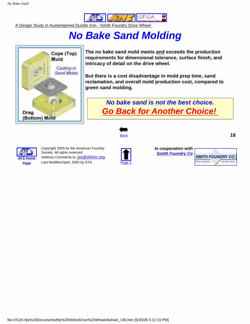
No Bake Sand Molding The no bake sand mold meets and exceeds the production requirements for dimensional tolerance, surface finish, and intricacy of detail on the drive wheel.
But there is a cost disadvantage in mold prep time, sand reclamation, and overall mold production cost, compared to green sand molding.
No bake sand is not the best choice.Go Back for Another Choice!
Back 18
AFS Home Page
Copyright 2005 by the American Foundry Society. All rights reserved. Address Comments to: [email protected]. Last Modified:April, 2005 by STG Page 1
In cooperation withSmith Foundry Co
file:///C|/A-My%20Documents/My%20Webs/Drive%20Wheel/dwheel_13b.htm [5/25/05 5:12:19 PM]
Cores and Machining
A Design Study in Austempered Ductile Iron - Smith Foundry Drive Wheel
Cores versus Machining
Two Step Machine
Center Core & Machine
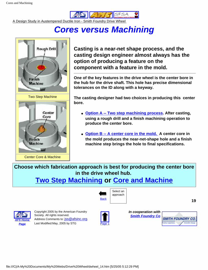
Casting is a near-net shape process, and the casting design engineer almost always has the option of producing a feature on the component with a feature in the mold.
One of the key features in the drive wheel is the center bore in the hub for the drive shaft. This hole has precise dimensional tolerances on the ID along with a keyway.
The casting designer had two choices in producing this center bore.
● Option A -- Two step machining process. After casting, using a rough drill and a finish machining operation to produce the center bore.
● Option B -- A center core in the mold. A center core in the mold produces the near-net-shape hole and a finish machine step brings the hole to final specifications.
Choose which fabrication approach is best for producing the center bore in the drive wheel hub.
Two Step Machining or Core and Machine
Back
Select an approach
19
AFS Home Page
Copyright 2005 by the American Foundry Society. All rights reserved. Address Comments to: [email protected]. Last Modified:May, 2005 by STG Page 1
In cooperation withSmith Foundry Co
file:///C|/A-My%20Documents/My%20Webs/Drive%20Wheel/dwheel_14.htm [5/25/05 5:12:29 PM]
Two Step Machining
A Design Study in Austempered Ductile Iron - Smith Foundry Drive Wheel
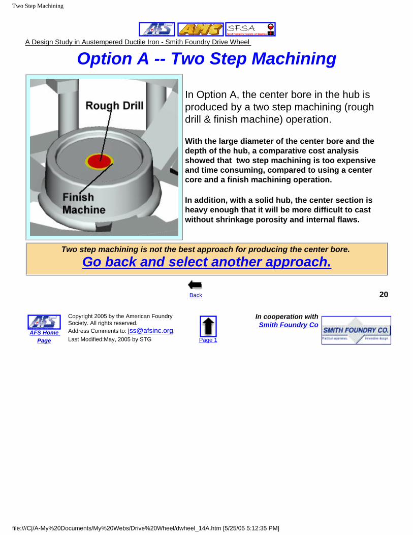
Option A -- Two Step Machining
In Option A, the center bore in the hub is produced by a two step machining (rough drill & finish machine) operation.
With the large diameter of the center bore and the depth of the hub, a comparative cost analysis showed that two step machining is too expensive and time consuming, compared to using a center core and a finish machining operation.
In addition, with a solid hub, the center section is heavy enough that it will be more difficult to cast without shrinkage porosity and internal flaws.
Two step machining is not the best approach for producing the center bore.
Go back and select another approach.
Back 20
AFS Home Page
Copyright 2005 by the American Foundry Society. All rights reserved. Address Comments to: [email protected]. Last Modified:May, 2005 by STG Page 1
In cooperation withSmith Foundry Co
file:///C|/A-My%20Documents/My%20Webs/Drive%20Wheel/dwheel_14A.htm [5/25/05 5:12:35 PM]
Core and Finish Machine
A Design Study in Austempered Ductile Iron - Smith Foundry Drive Wheel
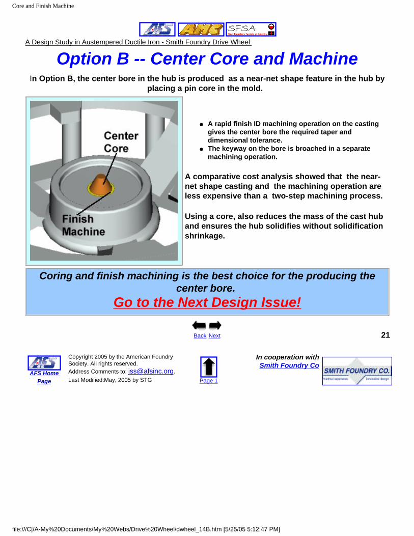
Option B -- Center Core and MachineIn Option B, the center bore in the hub is produced as a near-net shape feature in the hub by
placing a pin core in the mold.
● A rapid finish ID machining operation on the casting gives the center bore the required taper and dimensional tolerance.
● The keyway on the bore is broached in a separate machining operation.
A comparative cost analysis showed that the near-net shape casting and the machining operation are less expensive than a two-step machining process.
Using a core, also reduces the mass of the cast hub and ensures the hub solidifies without solidification shrinkage.
Coring and finish machining is the best choice for the producing the center bore.
Go to the Next Design Issue!
Back Next 21
AFS Home Page
Copyright 2005 by the American Foundry Society. All rights reserved. Address Comments to: [email protected]. Last Modified:May, 2005 by STG Page 1
In cooperation withSmith Foundry Co
file:///C|/A-My%20Documents/My%20Webs/Drive%20Wheel/dwheel_14B.htm [5/25/05 5:12:47 PM]
Risers and Gating
A Design Study in Austempered Ductile Iron - Smith Foundry Drive Wheel
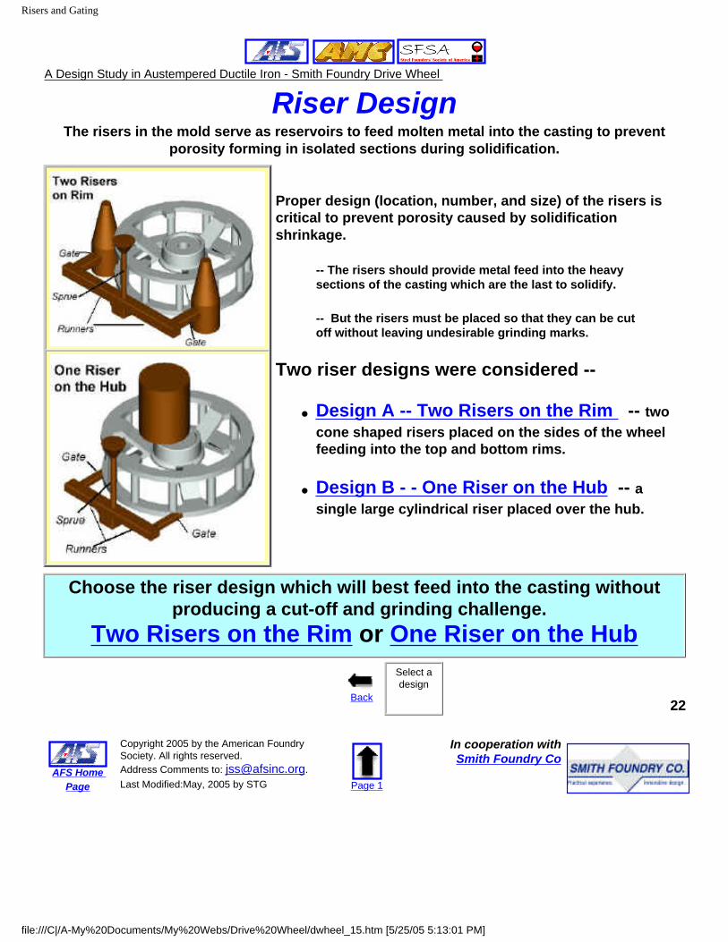
Riser DesignThe risers in the mold serve as reservoirs to feed molten metal into the casting to prevent
porosity forming in isolated sections during solidification.
Proper design (location, number, and size) of the risers is critical to prevent porosity caused by solidification shrinkage.
-- The risers should provide metal feed into the heavy sections of the casting which are the last to solidify.
-- But the risers must be placed so that they can be cut off without leaving undesirable grinding marks.
Two riser designs were considered --
● Design A -- Two Risers on the Rim -- two cone shaped risers placed on the sides of the wheel feeding into the top and bottom rims.
● Design B - - One Riser on the Hub -- a single large cylindrical riser placed over the hub.
Choose the riser design which will best feed into the casting without producing a cut-off and grinding challenge.
Two Risers on the Rim or One Riser on the Hub
Back
Select a design
22
AFS Home Page
Copyright 2005 by the American Foundry Society. All rights reserved. Address Comments to: [email protected]. Last Modified:May, 2005 by STG Page 1
In cooperation withSmith Foundry Co
file:///C|/A-My%20Documents/My%20Webs/Drive%20Wheel/dwheel_15.htm [5/25/05 5:13:01 PM]
Rim Risers
A Design Study in Austempered Ductile Iron - Smith Foundry Drive Wheel
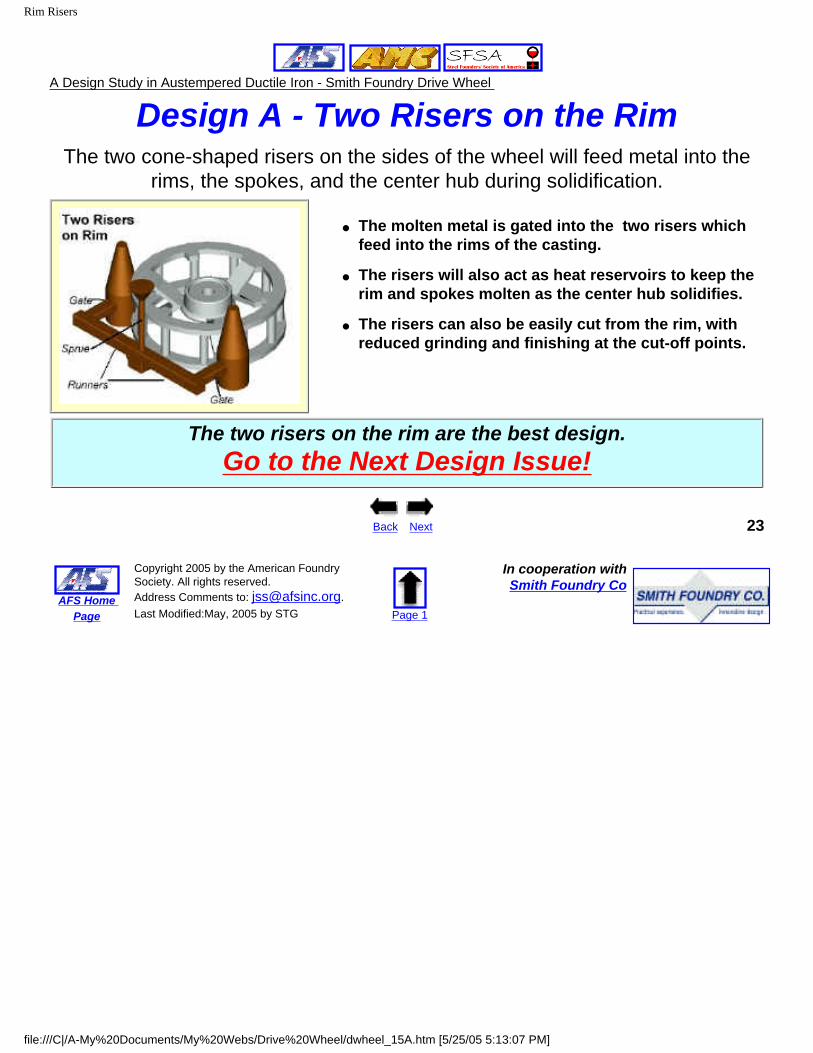
Design A - Two Risers on the RimThe two cone-shaped risers on the sides of the wheel will feed metal into the
rims, the spokes, and the center hub during solidification.
● The molten metal is gated into the two risers which feed into the rims of the casting.
● The risers will also act as heat reservoirs to keep the rim and spokes molten as the center hub solidifies.
● The risers can also be easily cut from the rim, with reduced grinding and finishing at the cut-off points.
The two risers on the rim are the best design.Go to the Next Design Issue!
Back Next 23
AFS Home Page
Copyright 2005 by the American Foundry Society. All rights reserved. Address Comments to: [email protected]. Last Modified:May, 2005 by STG Page 1
In cooperation withSmith Foundry Co
file:///C|/A-My%20Documents/My%20Webs/Drive%20Wheel/dwheel_15A.htm [5/25/05 5:13:07 PM]
Hub Riser
A Design Study in Austempered Ductile Iron - Smith Foundry Drive Wheel
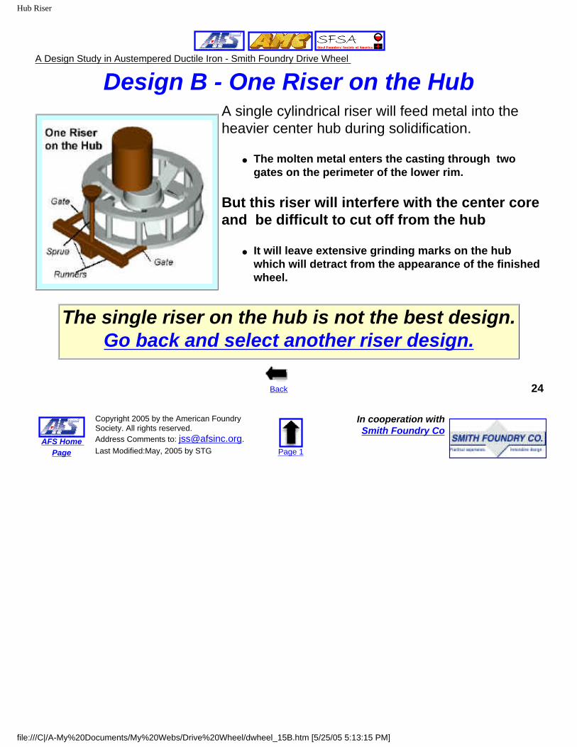
Design B - One Riser on the HubA single cylindrical riser will feed metal into the heavier center hub during solidification.
● The molten metal enters the casting through two gates on the perimeter of the lower rim.
But this riser will interfere with the center core and be difficult to cut off from the hub
● It will leave extensive grinding marks on the hub which will detract from the appearance of the finished wheel.
The single riser on the hub is not the best design.Go back and select another riser design.
Back 24
AFS Home Page
Copyright 2005 by the American Foundry Society. All rights reserved. Address Comments to: [email protected]. Last Modified:May, 2005 by STG Page 1
In cooperation withSmith Foundry Co
file:///C|/A-My%20Documents/My%20Webs/Drive%20Wheel/dwheel_15B.htm [5/25/05 5:13:15 PM]
Final Mold Design
A Design Study in Austempered Ductile Iron - Smith Foundry Drive Wheel
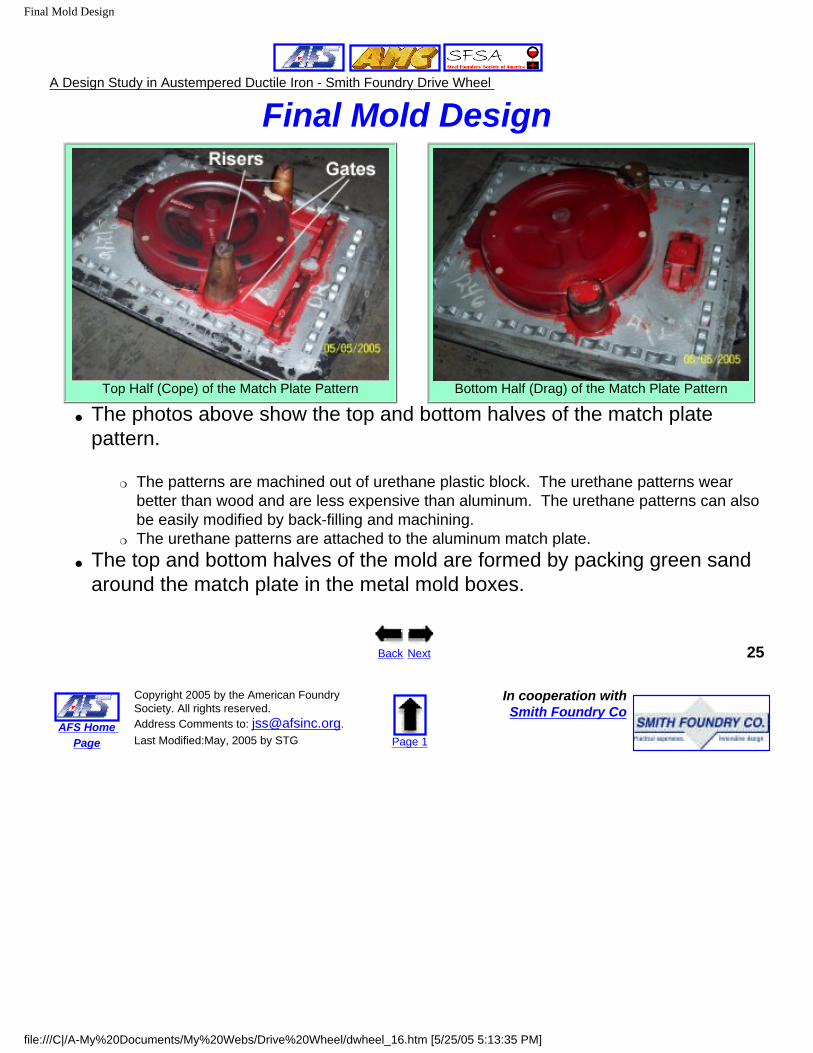
Final Mold Design
Top Half (Cope) of the Match Plate Pattern Bottom Half (Drag) of the Match Plate Pattern
● The photos above show the top and bottom halves of the match plate pattern.
❍ The patterns are machined out of urethane plastic block. The urethane patterns wear better than wood and are less expensive than aluminum. The urethane patterns can also be easily modified by back-filling and machining.
❍ The urethane patterns are attached to the aluminum match plate.● The top and bottom halves of the mold are formed by packing green sand
around the match plate in the metal mold boxes.
Back Next 25
AFS Home Page
Copyright 2005 by the American Foundry Society. All rights reserved. Address Comments to: [email protected]. Last Modified:May, 2005 by STG Page 1
In cooperation withSmith Foundry Co
file:///C|/A-My%20Documents/My%20Webs/Drive%20Wheel/dwheel_16.htm [5/25/05 5:13:35 PM]
Cores
A Design Study in Austempered Ductile Iron - Smith Foundry Drive Wheel
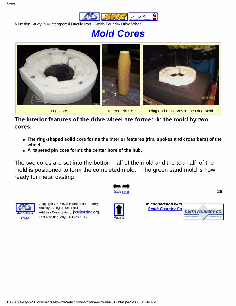
Mold Cores
Ring Core Tapered Pin Core Ring and Pin Cores in the Drag Mold
The interior features of the drive wheel are formed in the mold by two cores.
● The ring-shaped solid core forms the interior features (rim, spokes and cross bars) of the wheel
● A tapered pin core forms the center bore of the hub.
The two cores are set into the bottom half of the mold and the top half of the mold is positioned to form the completed mold. The green sand mold is now ready for metal casting.
Back Next 26
AFS Home Page
Copyright 2005 by the American Foundry Society. All rights reserved. Address Comments to: [email protected]. Last Modified:May, 2005 by STG Page 1
In cooperation withSmith Foundry Co
file:///C|/A-My%20Documents/My%20Webs/Drive%20Wheel/dwheel_17.htm [5/25/05 5:13:46 PM]
Process Steps
A Design Study in Austempered Ductile Iron - Smith Foundry Drive Wheel
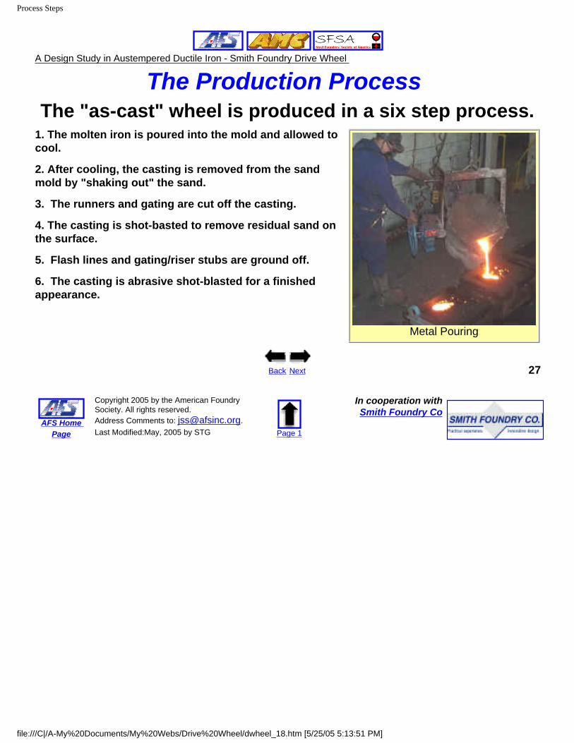
The Production Process The "as-cast" wheel is produced in a six step process.
1. The molten iron is poured into the mold and allowed to cool.
2. After cooling, the casting is removed from the sand mold by "shaking out" the sand.
3. The runners and gating are cut off the casting.
4. The casting is shot-basted to remove residual sand on the surface.
5. Flash lines and gating/riser stubs are ground off.
6. The casting is abrasive shot-blasted for a finished appearance.
Metal Pouring
Back Next 27
AFS Home Page
Copyright 2005 by the American Foundry Society. All rights reserved. Address Comments to: [email protected]. Last Modified:May, 2005 by STG Page 1
In cooperation withSmith Foundry Co
file:///C|/A-My%20Documents/My%20Webs/Drive%20Wheel/dwheel_18.htm [5/25/05 5:13:51 PM]
Machining
A Design Study in Austempered Ductile Iron - Smith Foundry Drive Wheel
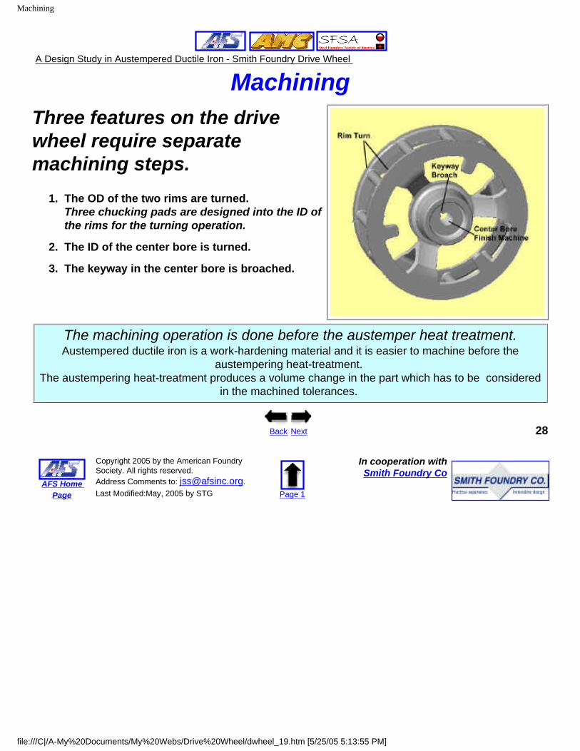
MachiningThree features on the drive wheel require separate machining steps.
1. The OD of the two rims are turned.Three chucking pads are designed into the ID of the rims for the turning operation.
2. The ID of the center bore is turned.
3. The keyway in the center bore is broached.
The machining operation is done before the austemper heat treatment.Austempered ductile iron is a work-hardening material and it is easier to machine before the
austempering heat-treatment. The austempering heat-treatment produces a volume change in the part which has to be considered
in the machined tolerances.
Back Next 28
AFS Home Page
Copyright 2005 by the American Foundry Society. All rights reserved. Address Comments to: [email protected]. Last Modified:May, 2005 by STG Page 1
In cooperation withSmith Foundry Co
file:///C|/A-My%20Documents/My%20Webs/Drive%20Wheel/dwheel_19.htm [5/25/05 5:13:55 PM]
Heat Treating
A Design Study in Austempered Ductile Iron - Smith Foundry Drive Wheel
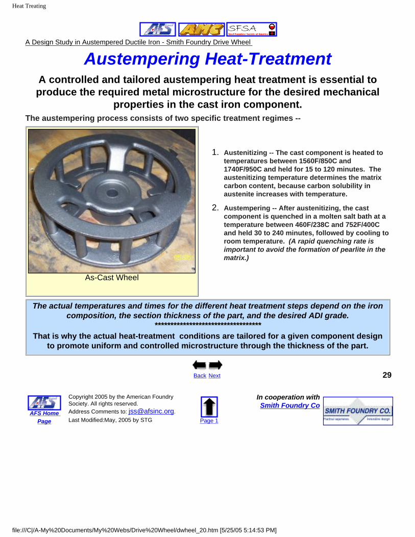
Austempering Heat-TreatmentA controlled and tailored austempering heat treatment is essential to produce the required metal microstructure for the desired mechanical
properties in the cast iron component. The austempering process consists of two specific treatment regimes --
As-Cast Wheel
1. Austenitizing -- The cast component is heated to temperatures between 1560F/850C and 1740F/950C and held for 15 to 120 minutes. The austenitizing temperature determines the matrix carbon content, because carbon solubility in austenite increases with temperature.
2. Austempering -- After austenitizing, the cast component is quenched in a molten salt bath at a temperature between 460F/238C and 752F/400C and held 30 to 240 minutes, followed by cooling to room temperature. (A rapid quenching rate is important to avoid the formation of pearlite in the matrix.)
The actual temperatures and times for the different heat treatment steps depend on the iron composition, the section thickness of the part, and the desired ADI grade.
**********************************That is why the actual heat-treatment conditions are tailored for a given component design
to promote uniform and controlled microstructure through the thickness of the part.
Back Next 29
AFS Home Page
Copyright 2005 by the American Foundry Society. All rights reserved. Address Comments to: [email protected]. Last Modified:May, 2005 by STG Page 1
In cooperation withSmith Foundry Co
file:///C|/A-My%20Documents/My%20Webs/Drive%20Wheel/dwheel_20.htm [5/25/05 5:14:53 PM]
Quality Assurance
A Design Study in Austempered Ductile Iron - Smith Foundry Drive Wheel
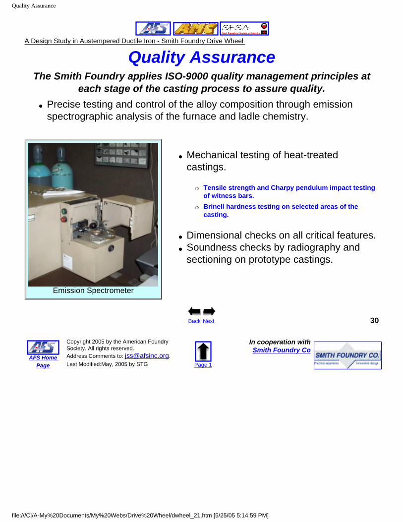
Quality AssuranceThe Smith Foundry applies ISO-9000 quality management principles at
each stage of the casting process to assure quality. ● Precise testing and control of the alloy composition through emission
spectrographic analysis of the furnace and ladle chemistry.
Emission Spectrometer
● Mechanical testing of heat-treated castings.
❍ Tensile strength and Charpy pendulum impact testing of witness bars.
❍ Brinell hardness testing on selected areas of the casting.
● Dimensional checks on all critical features.● Soundness checks by radiography and
sectioning on prototype castings.
Back Next 30
AFS Home Page
Copyright 2005 by the American Foundry Society. All rights reserved. Address Comments to: [email protected]. Last Modified:May, 2005 by STG Page 1
In cooperation withSmith Foundry Co
file:///C|/A-My%20Documents/My%20Webs/Drive%20Wheel/dwheel_21.htm [5/25/05 5:14:59 PM]
Lessons Learned
A Design Study in Austempered Ductile Iron - Smith Foundry Drive Wheel
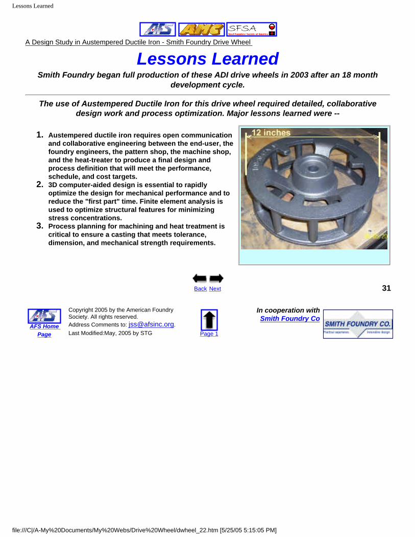
Lessons LearnedSmith Foundry began full production of these ADI drive wheels in 2003 after an 18 month
development cycle.
The use of Austempered Ductile Iron for this drive wheel required detailed, collaborative design work and process optimization. Major lessons learned were --
1. Austempered ductile iron requires open communication and collaborative engineering between the end-user, the foundry engineers, the pattern shop, the machine shop, and the heat-treater to produce a final design and process definition that will meet the performance, schedule, and cost targets.
2. 3D computer-aided design is essential to rapidly optimize the design for mechanical performance and to reduce the "first part" time. Finite element analysis is used to optimize structural features for minimizing stress concentrations.
3. Process planning for machining and heat treatment is critical to ensure a casting that meets tolerance, dimension, and mechanical strength requirements.
Back Next 31
AFS Home Page
Copyright 2005 by the American Foundry Society. All rights reserved. Address Comments to: [email protected]. Last Modified:May, 2005 by STG Page 1
In cooperation withSmith Foundry Co
file:///C|/A-My%20Documents/My%20Webs/Drive%20Wheel/dwheel_22.htm [5/25/05 5:15:05 PM]
Summary
A Design Study in Austempered Ductile Iron - Smith Foundry Drive Wheel
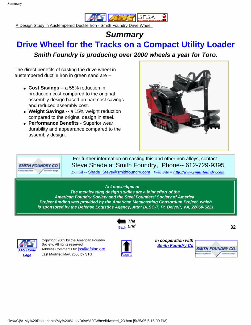
Summary Drive Wheel for the Tracks on a Compact Utility Loader
Smith Foundry is producing over 2000 wheels a year for Toro.
The direct benefits of casting the drive wheel in austempered ductile iron in green sand are --
● Cost Savings -- a 55% reduction in production cost compared to the original assembly design based on part cost savings and reduced assembly cost.
● Weight Savings -- a 15% weight reduction compared to the original design in steel.
● Performance Benefits - Superior wear, durability and appearance compared to the assembly design.
For further information on casting this and other iron alloys, contact -- Steve Shade at Smith Foundry, Phone-- 612-729-9395 E-mail -- [email protected] Web Site = http://www.smithfoundry.com
Acknowledgment --The metalcasting design studies are a joint effort of the
American Foundry Society and the Steel Founders' Society of America .Project funding was provided by the American Metalcasting Consortium Project, which
is sponsored by the Defense Logistics Agency, Attn: DLSC-T, Ft. Belvoir, VA, 22060-6221
Back
The End 32
AFS Home Page
Copyright 2005 by the American Foundry Society. All rights reserved. Address Comments to: [email protected]. Last Modified:May, 2005 by STG Page 1
In cooperation withSmith Foundry Co
file:///C|/A-My%20Documents/My%20Webs/Drive%20Wheel/dwheel_23.htm [5/25/05 5:15:09 PM]