a convenient nuclear resonance magnetometer
TRANSCRIPT

This content has been downloaded from IOPscience. Please scroll down to see the full text.
Download details:
IP Address: 129.130.252.222
This content was downloaded on 19/07/2014 at 08:56
Please note that terms and conditions apply.
A convenient nuclear resonance magnetometer
View the table of contents for this issue, or go to the journal homepage for more
1987 J. Phys. E: Sci. Instrum. 20 502
(http://iopscience.iop.org/0022-3735/20/5/005)
Home Search Collections Journals About Contact us My IOPscience
P T Squire and M R J Gibbs J. Phys. E: Sci. Instrum. 20 (1987). Printed in the UK
By operating in the pulsed mode the system is capable of measuring saturation magnetostriction with a sensitivity of 10-8.
One useful improvement that would make calibration simpler and more repeatable would be to operate the system in a closed-loop mode. In this the signal from the phase-sensitive detector would be fed back to a piezoelectric shifter that would maintain the output close to zero. The voltage applied to the piezoelectric shifter would then be a precise measure of the displacement, independent of the slope of the open-loop calibration curve.
Acknowledgments The authors are grateful to the School of Physics, University of Bath, for providing facilities for this work. Part of the equipment was funded by a cooperative award from SERC and STL. Mr M Tatar constructed the apparatus. The nickel and Mumetal samples were kindly provided by Dr R V Major of Telcon Metals Ltd.
References Bozorth R M 195 1 Ferromagnetism (Princeton, NJ: Van Nostrand) Kabacoff L T, Wun-Fogle M and Bucholz F 1985 Thermal, magnetic and magnetomechanical properties of amorphous Fe80-,Ni,Bls si3 IEEE Trans. Magn. MAG-21 2014-6 Lachowicz H K and Szymczak H 1984 Magnetostriction of amorphous magnetic materials J. Magn. Magn. Mater. 41 321-34
A convenient nuclear resonance magnetometer F N H Robinson Clarendon Laboratory, University of Oxford, Parks Road, Oxford OX1 3PU, UK
Received 6 August 1986
Abstract. A design is given for a low-noise limited oscillator whose inherent sensitivity is then sacrificed for the practical convenience of having remotely controlled varicap diode tuning and small diameter probes. A series of seven probes. each tunable over more than an octave, covers 1.36 to 60 MHz in overlapping ranges.
Mechanically driven tuning is always a problem in NMR
magnetometers, it leads to microphonic noise and the size of the capacitor and drive mechanism that has to be built in to the RF
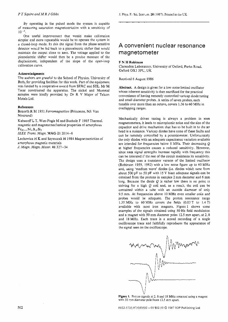
head is a nuisance. Varicap diodes have none of these faults and can be remotely controlled by a potentiometer. Unfortunately the only diodes with an adequate capacitance variation available are intended for frequencies below 5 MHz. Their decreasing Q at higher frequencies causes a reduced sensitivity. However, since NMR signal strengths increase rapidly with frequency this can be tolerated if the rest of the circuit maintains its sensitivity. The design uses a transistor version of the limited oscillator (Robinson 1959, 1982) with a low noise figure up to 60 MHz and, using ‘medium wave’ diodes (i.e. diodes which tune from about 500 pF to 50 pF with 15 V bias) adequate signals can be obtained from the protons in samples 2 mm diameter and 6 mm long. Because the diode Q is rather low there is no point in striving for a high Q coil and, as a result, the coil can be contained within a tube with an outside diameter of only 9.5 mm. At frequencies above 10 MHz even smaller coils and probes would be adequate. The proton resonance range 1.35 MHz to 60 MHz covers the fields (0.03 T to 1.4 T) available with most iron magnets. Figure 1 shows some examples of the signals obtained using 50 Hz field modulation and a magnet with 50 mm diameter poles 12.5 mm apart, at 2 , 8 and 18 MHz. Each trace is a stored recording of a single oscilloscope trace and faithfully reproduces the appearance of the signal seen on the oscilloscope.
h
Figure 1. Proton signals at 2, 8 and 18 MHz obtained using a magnet with 50 mm diameter pole faces 12.5 mm apart.
502 0022-3735/87/050502 + 03 $02.50 0 1987 IOP Publishing Ltd
A convenient nuclear resonance magnetometer
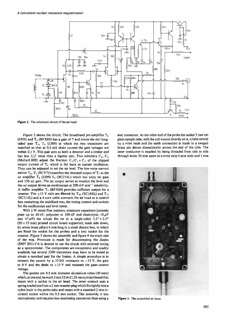
Figure 2. The schematic circuit of the RF head.
Figure 2 shows the circuit. The broadband pre-amplifier TI (5309) and T2 (BFX89) has a gain of 7 and drives the FET long- tailed pair T3, T, (5309) in which the two transistors are matched so that at 0.5 mA drain current the gate voltages are within 0.1 V. This pair acts as both a detector and a limiter and has less 1/ f noise than a bipolar pair. Two trimmers C , , C1 (Mullard 808) adjust the fraction CI/C1 + C2 of the clipped output current of T4 which is fed back to sustain oscillation. They can be adjusted to set the RF level. The low-noise current mirror T6, TI (BCY71) transfers the detected output of T, to the LF amplifier TB (5309) Tg (BC214L) which has unity DC gain and 150 AC gain. The DC output serves to monitor the level and the AC output drives an oscilloscope at 200 mV mm-I sensitivity. A buffer amplifier TS (BFX89) provides sufficient output for a counter. The f 15 V rails are filtered by Tlo (BC184L) and T I I (BC2 14L) and a 4-core cable connects the RF head to a control box containing the stabilised PSU, the tuning control and sockets for the oscilloscope and level meter.
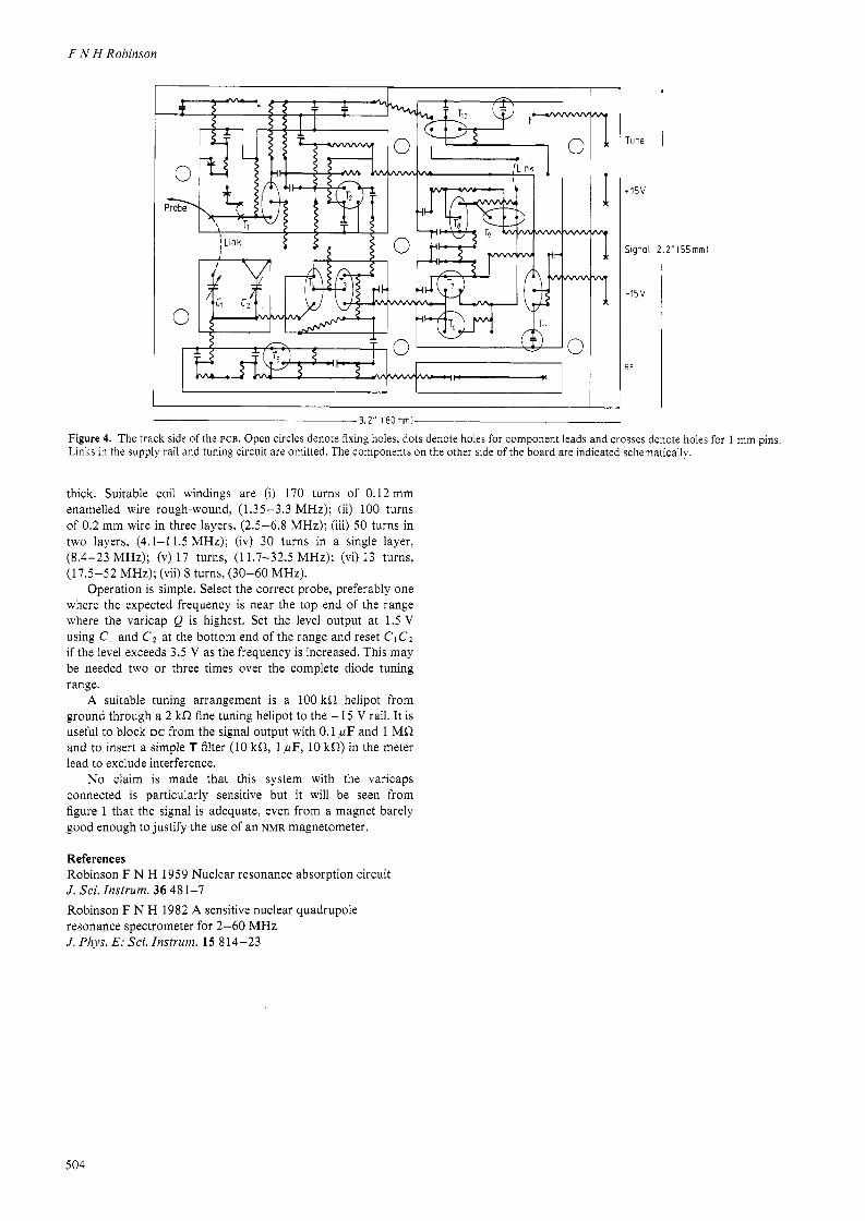
With Q W metal-film resistors, miniature capacitors (ceramic plate up to 10 nF, polyester at 100 n F and electrolytic 1 0 p F and 4 7 p F ) the circuit fits on to a single-sided 3.2" x 2.2" (80 x 55 mm) printed circuit board supported, track side down, by seven brass pillars 6 mm long in a small diecast box, to which are fitted the socket for the probes and a BNC socket for the counter. Figure 3 shows the assembly and figure 4 the track side of the PCB. Provision is made for disconnecting the diodes (SMV 201) if it is desired to use the circuit with external tuning as a spectrometer. The components are inexpensive and readily available but several 5309 transistors may have to be tested to obtain a matched pair for the limiter. A simple procedure is to connect the source by a 33 kR resistance to -15 V, the gate to 0 V and the drain to + I5 V and measure the gate-source voltage.
The probes are 9.5 mm diameter aluminium tubes (20 SWG)
which,atoneend,havea9.5 mm32TPr( 1.26 turns/mm)threadthat mates with a socket in the RF head. The inner contact uses a spring loaded pin from a 2 mm wander plug which fits tightly intoa nylon bush in the probe tube and mates with a standard 2 mm in- sulated socket within the 9.5 mm socket. This assembly is less microphonic and requires less machining operations than using a
BNC connector. At the other end of the probe the sealed 3 mm OD glass sample tube, with the coil wound directly on it, is held central by a PTFE bush and the earth connection is made to a swaged brass pin driven diametrically across the end of the tube. The inner conductor is steadied by being threaded from side to side through holes 30 mm apart in a PTFE strip 6 mm wide and 1 mm
Figure 3. The assembled RF head.
503
F N H Robinson
I I I I I
I Tune
+15V
Signal Z . Z " I 5 5 m m )
-15v
E F
3.2'' I d o m m i
Figure 4. The track side of the PCB. Open circles denote fixing holes, dots denote holes for component leads and crosses denote holes for 1 mm pins. Links in the supply rail and tuning circuit are omitted. The components on the other side of the board are indicated schematically.
thick. Suitable coil windings are (i) 170 turns of 0.12 mm enamelled wire rough-wound, (1.35-3.3 MHz); (ii) 100 turns of 0.2 mm wire in three layers, (2.5-6.8 MHz); (iii) 50 turns in two layers, (4.1-1 1.5 MHz); (iv) 30 turns in a single layer. (8.4-23 MHz); (v) 1 7 turns, (11.7-32.5 MHz); (vi) 13 turns. (17.5-52 MHz); (vii) 8 turns, (30-60 MHz).
Operation is simple. Select the correct probe, preferably one where the expected frequency is near the top end of the range where the varicap Q is highest. Set the level output at 1.5 V using C1 and Cz at the bottom end of the range and reset C1 C1 if the level exceeds 3.5 V as the frequency is increased. This may be needed two or three times over the complete diode tuning range.
A suitable tuning arrangement is a 100 kR helipot from ground through a 2 kR fine tuning helipot to the + 15 V rail. It is useful to block DC from the signal output with 0.1 p F and 1 MR and to insert a simple T filter (10 kR, 1 ,uF, 10 kR) in the meter lead to exclude interference.
No claim is made that this system with the varicaps connected is particularly sensitive but it will be seen from figure 1 that the signal is adequate, even from a magnet barely good enough to justify the use of an NMR magnetometer.
References Robinson F N H 1959 Nuclear resonance absorption circuit J . Sci. Instrum. 36 48 1-7 Robinson F N H 1982 A sensitive nuclear quadrupole resonance spectrometer for 2-60 MHz J. Phys. E: Sci. Instrum. 15 814-23
504