a control system and power electronic for an electric...
TRANSCRIPT
A control system and power electronic for an electric powertrain implemented on a go-kartMaster of Science Thesis in the Programme Integrated Electronic System
Design
Fredrik LönnbladAndreas Öhlund
Chalmers University of TechnologyUniversity of GothenburgDepartment of Computer Science and EngineeringGöteborg, Sweden, December 2012

The Author grants to Chalmers University of Technology and University of Gothenburg the non-exclusive right to publish the Work electronically and in a non-commercial purpose make it accessible on the Internet. The Author warrants that he/she is the author to the Work, and warrants that the Work does not contain text, pictures or other material that violates copyright law.
The Author shall, when transferring the rights of the Work to a third party (for example a publisher or a company), acknowledge the third party about this agreement. If the Author has signed a copyright agreement with a third party regarding the Work, the Author warrants hereby that he/she has obtained any necessary permission from this third party to let Chalmers University of Technology and University of Gothenburg store the Work electronically and make it accessible on the Internet.
A control system and power electronic for an electric powertrain implemented on a go-kart
Fredrik LönnbladAndreas Öhlund
© Fredrik Lönnblad, December 2012.© Andreas Öhlund, December 2012.
Examiner: Lars Svensson
Chalmers University of TechnologyUniversity of GothenburgDepartment of Computer Science and EngineeringSE-412 96 GöteborgSwedenTelephone + 46 (0)31-772 1000
Department of Computer Science and EngineeringGöteborg, Sweden December 2012

Acknowledgements
Thanks QRTECH AB for having us and all the help with thisproject.
3
Abstract
This report describes the master thesis project where a 3-phase AC-inverter is designed with software to space vector modulate the outputcurrents. The report outlines a brief background to the project andthen goes on to describe the demands that the inverter must fulfill. Thecontrolling software is described both in general and the applicationspecifics are treated. The hardware solution is described and majorcomponent choices are discussed. The complete working inverter wassuccessfully implemented on a go-kart, and the testing verifies thatthe functionality of the inverter is according to the specifications. Theinverter was not fully tested to the upper limits of 72V and 300Vpeak current due to lack of testing equipment, though the results arepromising for the inverter to be able to handle this.
4
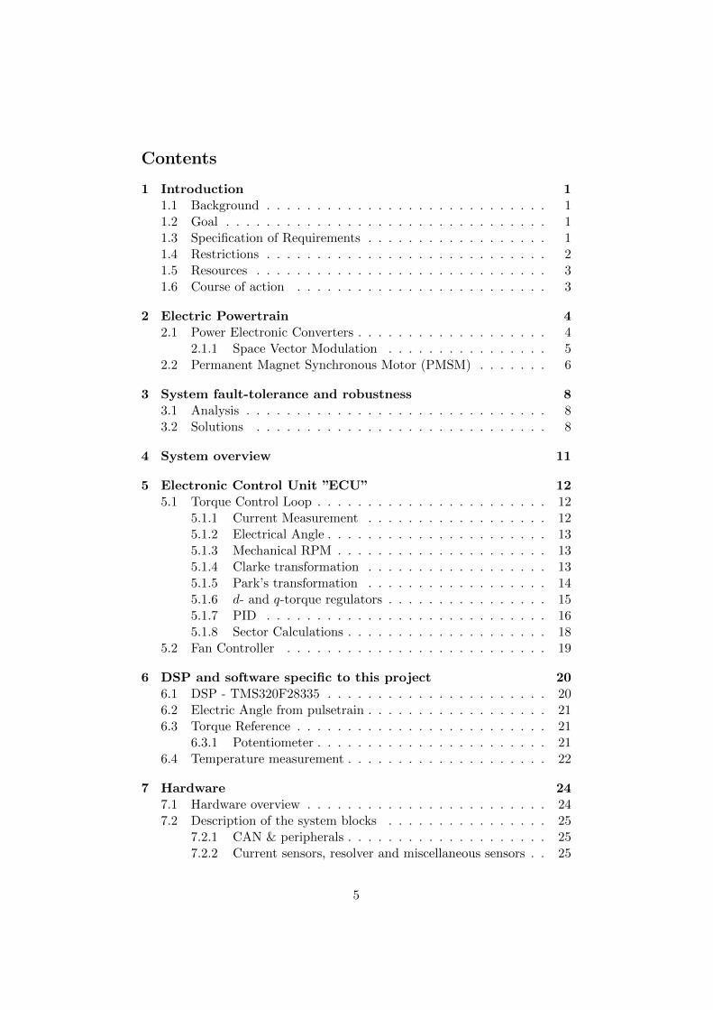
Contents
1 Introduction 11.1 Background . . . . . . . . . . . . . . . . . . . . . . . . . . . . 11.2 Goal . . . . . . . . . . . . . . . . . . . . . . . . . . . . . . . . 11.3 Specification of Requirements . . . . . . . . . . . . . . . . . . 11.4 Restrictions . . . . . . . . . . . . . . . . . . . . . . . . . . . . 21.5 Resources . . . . . . . . . . . . . . . . . . . . . . . . . . . . . 31.6 Course of action . . . . . . . . . . . . . . . . . . . . . . . . . 3
2 Electric Powertrain 42.1 Power Electronic Converters . . . . . . . . . . . . . . . . . . . 4
2.1.1 Space Vector Modulation . . . . . . . . . . . . . . . . 52.2 Permanent Magnet Synchronous Motor (PMSM) . . . . . . . 6
3 System fault-tolerance and robustness 83.1 Analysis . . . . . . . . . . . . . . . . . . . . . . . . . . . . . . 83.2 Solutions . . . . . . . . . . . . . . . . . . . . . . . . . . . . . 8
4 System overview 11
5 Electronic Control Unit ”ECU” 125.1 Torque Control Loop . . . . . . . . . . . . . . . . . . . . . . . 12
5.1.1 Current Measurement . . . . . . . . . . . . . . . . . . 125.1.2 Electrical Angle . . . . . . . . . . . . . . . . . . . . . . 135.1.3 Mechanical RPM . . . . . . . . . . . . . . . . . . . . . 135.1.4 Clarke transformation . . . . . . . . . . . . . . . . . . 135.1.5 Park’s transformation . . . . . . . . . . . . . . . . . . 145.1.6 d- and q-torque regulators . . . . . . . . . . . . . . . . 155.1.7 PID . . . . . . . . . . . . . . . . . . . . . . . . . . . . 165.1.8 Sector Calculations . . . . . . . . . . . . . . . . . . . . 18
5.2 Fan Controller . . . . . . . . . . . . . . . . . . . . . . . . . . 19
6 DSP and software specific to this project 206.1 DSP - TMS320F28335 . . . . . . . . . . . . . . . . . . . . . . 206.2 Electric Angle from pulsetrain . . . . . . . . . . . . . . . . . . 216.3 Torque Reference . . . . . . . . . . . . . . . . . . . . . . . . . 21
6.3.1 Potentiometer . . . . . . . . . . . . . . . . . . . . . . . 216.4 Temperature measurement . . . . . . . . . . . . . . . . . . . . 22
7 Hardware 247.1 Hardware overview . . . . . . . . . . . . . . . . . . . . . . . . 247.2 Description of the system blocks . . . . . . . . . . . . . . . . 25
7.2.1 CAN & peripherals . . . . . . . . . . . . . . . . . . . . 257.2.2 Current sensors, resolver and miscellaneous sensors . . 25
5
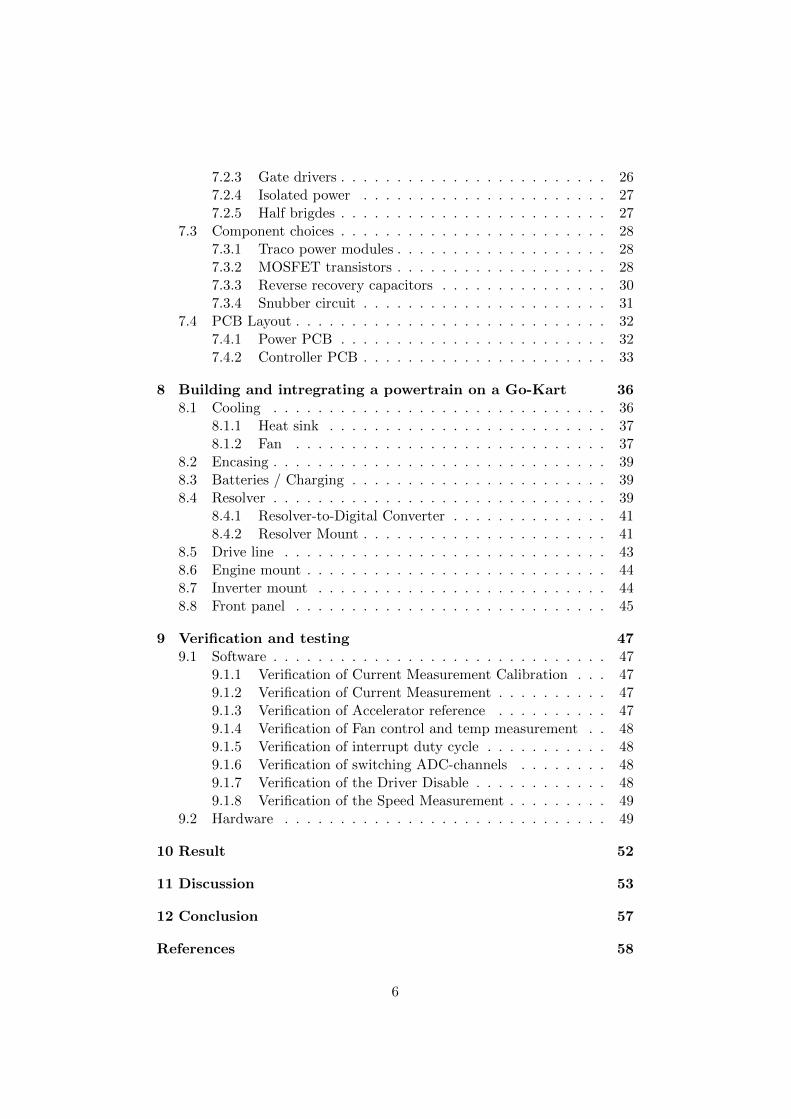
7.2.3 Gate drivers . . . . . . . . . . . . . . . . . . . . . . . . 267.2.4 Isolated power . . . . . . . . . . . . . . . . . . . . . . 277.2.5 Half brigdes . . . . . . . . . . . . . . . . . . . . . . . . 27
7.3 Component choices . . . . . . . . . . . . . . . . . . . . . . . . 287.3.1 Traco power modules . . . . . . . . . . . . . . . . . . . 287.3.2 MOSFET transistors . . . . . . . . . . . . . . . . . . . 287.3.3 Reverse recovery capacitors . . . . . . . . . . . . . . . 307.3.4 Snubber circuit . . . . . . . . . . . . . . . . . . . . . . 31
7.4 PCB Layout . . . . . . . . . . . . . . . . . . . . . . . . . . . . 327.4.1 Power PCB . . . . . . . . . . . . . . . . . . . . . . . . 327.4.2 Controller PCB . . . . . . . . . . . . . . . . . . . . . . 33
8 Building and intregrating a powertrain on a Go-Kart 368.1 Cooling . . . . . . . . . . . . . . . . . . . . . . . . . . . . . . 36
8.1.1 Heat sink . . . . . . . . . . . . . . . . . . . . . . . . . 378.1.2 Fan . . . . . . . . . . . . . . . . . . . . . . . . . . . . 37
8.2 Encasing . . . . . . . . . . . . . . . . . . . . . . . . . . . . . . 398.3 Batteries / Charging . . . . . . . . . . . . . . . . . . . . . . . 398.4 Resolver . . . . . . . . . . . . . . . . . . . . . . . . . . . . . . 39
8.4.1 Resolver-to-Digital Converter . . . . . . . . . . . . . . 418.4.2 Resolver Mount . . . . . . . . . . . . . . . . . . . . . . 41
8.5 Drive line . . . . . . . . . . . . . . . . . . . . . . . . . . . . . 438.6 Engine mount . . . . . . . . . . . . . . . . . . . . . . . . . . . 448.7 Inverter mount . . . . . . . . . . . . . . . . . . . . . . . . . . 448.8 Front panel . . . . . . . . . . . . . . . . . . . . . . . . . . . . 45
9 Verification and testing 479.1 Software . . . . . . . . . . . . . . . . . . . . . . . . . . . . . . 47
9.1.1 Verification of Current Measurement Calibration . . . 479.1.2 Verification of Current Measurement . . . . . . . . . . 479.1.3 Verification of Accelerator reference . . . . . . . . . . 479.1.4 Verification of Fan control and temp measurement . . 489.1.5 Verification of interrupt duty cycle . . . . . . . . . . . 489.1.6 Verification of switching ADC-channels . . . . . . . . 489.1.7 Verification of the Driver Disable . . . . . . . . . . . . 489.1.8 Verification of the Speed Measurement . . . . . . . . . 49
9.2 Hardware . . . . . . . . . . . . . . . . . . . . . . . . . . . . . 49
10 Result 52
11 Discussion 53
12 Conclusion 57
References 58
6

A Control PCB schematics I
B Power PCB schematics XVII
7
List of Abbreviations
AC Alternating Current
ADC Analog to Digital Converter
ATO Angle Tracing Observer
BEV Battery Electric Vehicle
CAN Controller Area Network
DC Direct current
DSP Digital Signal Processor
ECU Electric Control Unit
EMC Electro Magnetic Compatibility
EMI Electro Magnetic Interference
ESD Electro Static Discharge
EV Electric Vehicle
GND Ground
GPIO General Purpose Input Output
HEV Hybrid Electric Vehicle
IC Integrated Circuit
IGBT Isolated Gate Bipolar Transistor
IR Infra Red
JTAG Joint Test Action Group
LED Light Emitting Diode
LUT Look-Up Table
Mbps Mega bit per second
MOSFET Metal Oxide Semiconductor Field Effect Transistor
MSPS Mega Samples per Second
NTC Negative Temperature Coefficient
PCB Printed Circuit Board
PHEV Plug-in Hybrid Electric Vehicle
PMSM Permanent Magnet Synchronous Machine
8

PTC Positive Temperature Coefficient
PWM Pulse Width Modulation
QEP Quadrature Encoder Pulse
R/D Resolver to Digital
RMS Root Mean Square
RPM Revolutions Per Minutes
9
1 Introduction
This report describes a proposed design and its implementation for an in-verter and its control system in an electric powertrain. The report will alsoinclude sections on how this inverter was integrated in a real powertrain ona go-kart.
This introduction describes the motivations behind the project and how itwas carried out.
1.1 Background
Presently, roughly every sixth human on earth has a car in general, sum-ming up to a total of around a billion cars[1]. Looking at Sweden, aroundevery second citizen own a passenger car[2], if this would have been the caseglobally, the total number of cars in the world would be roughly 4 billion in2025[3]. However projections say that the number will be around 2 billion,largely a consequence of China’s and India’s growth, this is still a double tothe current amount. Given that greenhouse gases are already causing prob-lems with our climate, air-pollution is a major concern in our cities and thatconflicts in unstable oil-rich nations is a current reality, realistic solutionsneed to be found[1].
With this in mind QRTECH seeks to expand its current product portfo-lio within power electronics and develops DC/DC-converters, inverters, on-board chargers and battery systems for the automotive industry.
1.2 Goal
The primary goal of this project is to redesign an existing inverter to fit achanged set of demands. Analysis and implementation of safety mechanismsis also a central part to guarantee robustness and fault-tolerance. Second tothis is that the inverter is to be implemented with a complete drive line onan electric go-kart and make it drivable.
1.3 Specification of Requirements
This section describes a set of requirements that were developed out of dis-cussions between the project group and QRTECH.
Supply VoltageThe system shall be designed for a DC supply voltage between 40-70volts.
1
3 phase currentThe system shall be designed for a 3 phase AC and be able to handlepeaks up to 300A.
Torque controlThe system shall utilize a closed feedback-loop with a pair of torque-setpoints, current-measurement as feedback together with the rotor-angle of the PMSM.
CoolingThe system shall have both an active (fan) and a passive (heat sink)cooling system to prevent the inverter from overheating and possiblysustaining damage.
MechanicalThe system shall be implemented on a go-kart and therefore mechan-ical parts shall be designed and manufactured to enable this.
CANThe system shall have support for CAN-communication[4] to enablefuture development of communication and interactions with the in-verter.
Safety aspectsThe system shall be designed with safety aspects in terms fault-toleranceand robustness in mind.
Angle measurementThe system shall utilize resolver type sensor and a R/D (Resolverto Digital) Converter IC, prechoosen by QRTECH, for the the anglefeedback from the motor to the control loop.
1.4 Restrictions
This section presents some parts that are outside the scope of this projectand/or already a part of an older version of this system.
MotorThe motor is a part of the old system and is therefore predetermined.
Regenerative breakingSoftware implementation of regenerative breaking is outside the scopeof this project.
ChassiThe go-kart chassis is a part of the old project and is therefore prede-termined.
2
BatteryThe batteries are a part of the old project and are therefore predeter-mined.
DSPSince the DSP is prechoosen by QRTECH, analysis will not be carriedout.
CANSoftware implementation of CAN is outside the scope of this project.
1.5 Resources
In this section, a brief listing of the resources available for the project ispresented.
1600 man-hoursA total of 1600 man-hours over 20 weeks, divided on a 2 man groupare available.
QRTECH ABQRTECH AB offered a lot of the resources to make this project possi-ble. Among them are Supervisor and help from co-workers, lab equip-ment, software and budget.
ChalmersExaminer
E-sektionens Teletekniska AvdelningMechanical workshop and other tools and equipment.
1.6 Course of action
Here a coarse description of the planned course of action in this project ispresented.
• Prestudy of the inverters developed by QRTECH.
• Analysis of the safety and reliability needs
• Adaptation of the current hardware and software to this project
• Mechanical integration of the inverter
• Verification of the implementation
• Documentation
3
2 Electric Powertrain
In the automotive industry, the term powertrain refers to the system thatgenerates propulsion. This includes the whole chain of components thatgenerate power and delivers it to the road surface. In more detail, thismeans the engine, transmission, drive shafts, differentials and the wheels.
An electric vehicle (EV) is a vehicle that is powered, at least in part, byelectricity. EV configurations include battery electric vehicles (BEVs) whichare powered by 100% electric energy, various hybrid-electric vehicles (HEVs),and plug-in hybrid electric vehicles (PHEVs) [5].
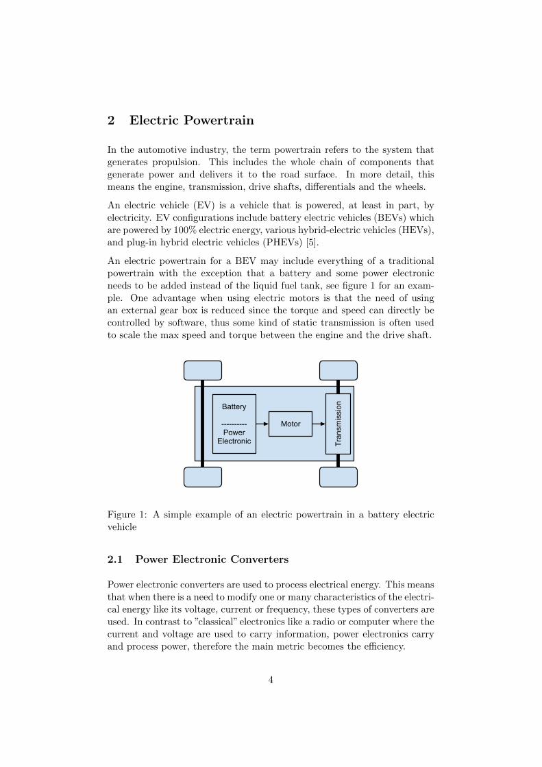
An electric powertrain for a BEV may include everything of a traditionalpowertrain with the exception that a battery and some power electronicneeds to be added instead of the liquid fuel tank, see figure 1 for an exam-ple. One advantage when using electric motors is that the need of usingan external gear box is reduced since the torque and speed can directly becontrolled by software, thus some kind of static transmission is often usedto scale the max speed and torque between the engine and the drive shaft.
Battery
----------Power
Electronic
Motor
Tran
smis
sion
Figure 1: A simple example of an electric powertrain in a battery electricvehicle
2.1 Power Electronic Converters
Power electronic converters are used to process electrical energy. This meansthat when there is a need to modify one or many characteristics of the electri-cal energy like its voltage, current or frequency, these types of converters areused. In contrast to ”classical” electronics like a radio or computer where thecurrent and voltage are used to carry information, power electronics carryand process power, therefore the main metric becomes the efficiency.
4
The power conversion systems can be classified according to the type of theinput and output power
• AC to DC (rectifier)
• DC to AC (inverter)
• DC to DC (DC to DC converter)
• AC to AC (AC to AC converter)
2.1.1 Space Vector Modulation
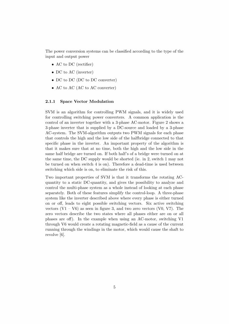
SVM is an algorithm for controlling PWM signals, and it is widely usedfor controlling switching power converters. A common application is thecontrol of an inverter together with a 3-phase AC-motor. Figure 2 shows a3-phase inverter that is supplied by a DC-source and loaded by a 3-phaseAC-system. The SVM-algorithm outputs two PWM signals for each phasethat controls the high and the low side of the halfbridge connected to thatspecific phase in the inverter. An important property of the algorithm isthat it makes sure that at no time, both the high and the low side in thesame half bridge are turned on. If both half’s of a bridge were turned on atthe same time, the DC supply would be shorted (ie. in 2, switch 1 may notbe turned on when switch 4 is on). Therefore a dead-time is used betweenswitching which side is on, to eliminate the risk of this.
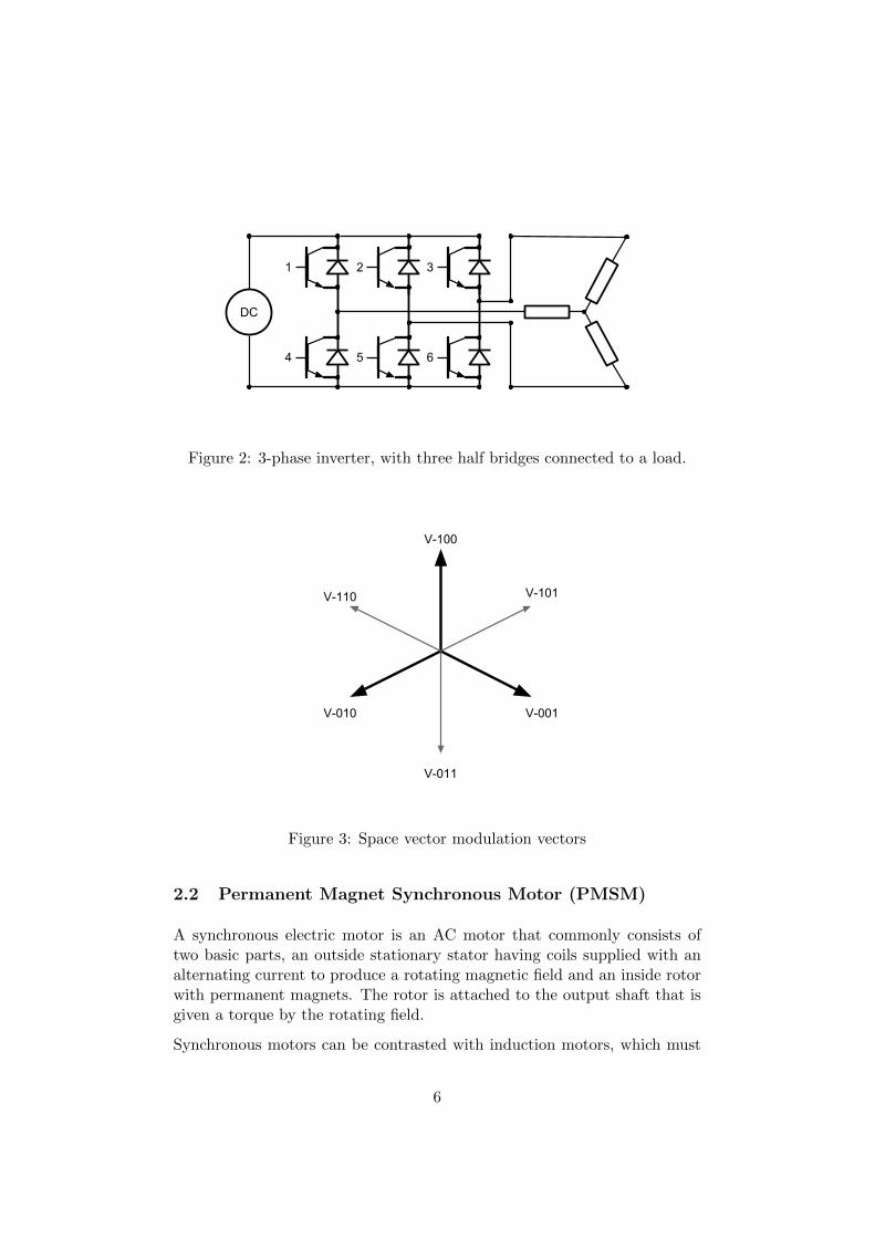
Two important properties of SVM is that it transforms the rotating AC-quantity to a static DC-quantity, and gives the possibility to analyze andcontrol the multi-phase system as a whole instead of looking at each phaseseparately. Both of these features simplify the control-loop. A three-phasesystem like the inverter described above where every phase is either turnedon or off, leads to eight possible switching vectors. Six active switchingvectors (V1 – V6) as seen in figure 3, and two zero vectors (V0, V7). Thezero vectors describe the two states where all phases either are on or allphases are off). In the example when using an AC-motor, switching V1through V6 would create a rotating magnetic-field as a cause of the currentrunning through the windings in the motor, which would cause the shaft torevolve [6].
5
DC
1 2 3
4 65
Figure 2: 3-phase inverter, with three half bridges connected to a load.
V-100
V-110
V-010
V-011
V-001
V-101
Figure 3: Space vector modulation vectors
2.2 Permanent Magnet Synchronous Motor (PMSM)
A synchronous electric motor is an AC motor that commonly consists oftwo basic parts, an outside stationary stator having coils supplied with analternating current to produce a rotating magnetic field and an inside rotorwith permanent magnets. The rotor is attached to the output shaft that isgiven a torque by the rotating field.
Synchronous motors can be contrasted with induction motors, which must
6

slip in order to produce torque. A PMSM operates synchronously with theAC frequency and the mechanical speed is determined by the number ofpairs of poles and the frequency.
Most synchronous motors are used where precise constant speed is required.It is a highly efficient mean of converting AC energy to mechanical workand a PMSM can also be used as an alternator to regain energy when anexternal torque is applied to the motor.
7
3 System fault-tolerance and robustness
This section will describe the safety factors that the inverter will need tohandle and how they are taken care of.
3.1 Analysis
Current shoot-throughThe inverter must be built to ensure that no shoot-through currentscan occur in any of the inverters half bridges.
HeatThe inverter must be able to handle the heat that the power compo-nents develop and have some protection in place to ensure that thehardware will not overheat and possibly sustain damage.
Electrical InterferenceThe inverter must be able to handle the interference itself and themotor produce during operation. However the inverter is not requiredto have EMC compliance with specifications such as those for CE-marking, since it is not required in this project.
Torque capThe inverter must have a torque cap implemented so that the systemwill not provide more current than the inverter is built for, to ensurethat the inverter itself or the motor it is driving will not sustain damagefrom over-current.
Voltage dropThe inverter must be able to handle voltage drops on the input power,since if the input voltage drops too much, control of the switchingmight fail due to some circuits not functioning properly.
3.2 Solutions
Current shoot-throughThere are several safety features to deal with this demand. Softwarefeatures ensure that both MOSFETs in any of the half bridges shouldnot be turned on at the same time. As well as the gate drivers whichhave a hardware solution that ensures a minimum dead band in theswitching and also never permits both transistors to be turned onsimultaneously.
8
HeatThis is an important consideration, since if the system is overheating,the circuitry might sustain damage and therefore multiple solutionshas been implemented.
• Two types of sensors for measuring the temperature have beenintegrated
– PTC resistors placed close to the half bridges on the powerPCB, that at a max allowed temperature trigger an interruptin the software that also automatically shuts down the gatedriver hardware. This puts the PWM signals that controlthe inverter to a low state.
– NTC resistor that is constantly sampled in the DSP to pro-duce a temperature reading of the power PCB.
• A heat sink that is mounted directly to the power-board.
• A fan to cool of the sink. This is controlled by a linearly regulatedPWM signal.
• A routine to reduce the torque if the heat sink and the fan is notenough to prevent the inverter from overheating.
Electrical InterferenceThe whole inverter has been designed with this in mind. Most of thecircuitry put in place to handle overshoots and oscillations are a partof the solutions to cope with this requirement. The layouts of bothPCBs have many considerations in an effort to minimize noise andsensitivity to noise. These considerations and the component choicesare described in much more detail in section 7.
Torque capA torque cap has been implemented in software to ensure that thesystem will not provide more current than the inverter is built for.
Driver DisableWhenever the system or the user decides that the system should bedisabled, the gate drivers that control the power PCB are switchedoff. This has two main positive effects; first, it will save energy sincethe drivers and the power PCB will stop switching; second is that ifsomething is malfunctioning, some part might be damaged if continuedswitching is allowed.
Voltage dropThis is taken care of by measuring the input DC-voltage from the bat-tery. A minimum voltage is defined as a constant that is larger than
9

the minimum required voltage for proper functionality of the electri-cal components. If the measured voltage drops below this constant,the system will start to regulate against zero torque. There is alsoa constant lower than this which is the limit for when the controllerwill disable the drivers and stop switching. If the latter happens, asoftware interrupt occurs and the inverter is disabled, and will need tobe reset for further operation.
10
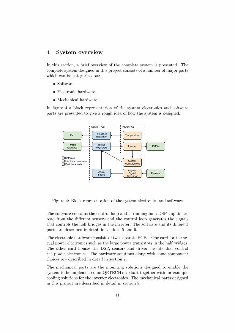
4 System overview
In this section, a brief overview of the complete system is presented. Thecomplete system designed in this project consists of a number of major partswhich can be categorized as:
• Software.
• Electronic hardware.
• Mechanical hardware.
In figure 4 a block representation of the system electronics and softwareparts are presented to give a rough idea of how the system is designed.
Current Measurement
TemperatureFan speed Regulator
AngleSpeed
Torque Regulators
Fan
Inverter
Peripheral units
SoftwareElectronic hardware
Angular Signal
ConverterResolver
Power PCBControl PCB
PMSMThrottle reference
Figure 4: Block representation of the system electronics and software
The software contains the control loop and is running on a DSP. Inputs areread from the different sensors and the control loop generates the signalsthat controls the half bridges in the inverter. The software and its differentparts are described in detail in sections 5 and 6.
The electronic hardware consists of two separate PCBs. One card for the ac-tual power electronics such as the large power transistors in the half bridges.The other card houses the DSP, sensors and driver circuits that controlthe power electronics. The hardware solutions along with some componentchoices are described in detail in section 7.
The mechanical parts are the mounting solutions designed to enable thesystem to be implemented on QRTECH’s go-kart together with for examplecooling solutions for the inverter electronics. The mechanical parts designedin this project are described in detail in section 8.
11
5 Electronic Control Unit ”ECU”
This chapter will describe a general theory behind an ECU for motor controland its sub blocks. It consists of routines for collecting and processing datafrom the inverter and peripheral units as well as controlling them, it handlessecurity and log data.
This section will not describe how the ECU interfaces to other units nor givea detailed description of the software implementation since that is specificto this project. Those parts is discussed in section 6.
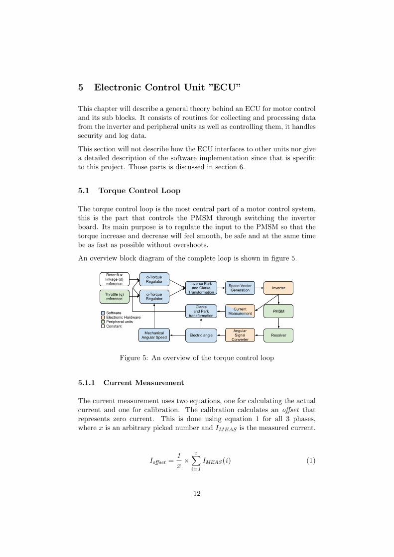
5.1 Torque Control Loop
The torque control loop is the most central part of a motor control system,this is the part that controls the PMSM through switching the inverterboard. Its main purpose is to regulate the input to the PMSM so that thetorque increase and decrease will feel smooth, be safe and at the same timebe as fast as possible without overshoots.
An overview block diagram of the complete loop is shown in figure 5.
Software
q-Torque Regulator
d-Torque Regulator Inverse Park
and Clarke Transformation
Space Vector Generation Inverter
Angular Signal
Converter
PMSM
Resolver
Throttle (q) reference
Rotor flux linkage (d) reference
Electric angle
Clarke and Park
transformation
Current Measurement
Mechanical Angular Speed
Electronic Hardware
ConstantPeripheral units
Figure 5: An overview of the torque control loop
5.1.1 Current Measurement
The current measurement uses two equations, one for calculating the actualcurrent and one for calibration. The calibration calculates an offset thatrepresents zero current. This is done using equation 1 for all 3 phases,where x is an arbitrary picked number and IMEAS is the measured current.
Ioffset =1
x×
x∑i=1
IMEAS (i) (1)
12
Equation 2 calculates the actual current, this is done for all 3 phases.
I = (IMEAS − Ioffset) (2)
5.1.2 Electrical Angle
The electrical angle is used as a feedback to know where the motor-shaft ispositioned. This information is used to calculate speed and as an input tothe space vector modulation. There is a number of ways to calculate theangle and the one used in the project is described in section 6.2.
5.1.3 Mechanical RPM
The mechanical RPM is calculated using equation 3 on the electrical angle(θ) described in section 5.1.2. The difference between mechanical and elec-trical RPM is the number of pole pairs in the motor, the electrical RPMdescribes how fast the magnetic field in the motor is rotating in contrast tomechanical RPM which describes the speed of the motor shaft. The sampletime (t) is in seconds which is why the ∆θ is multiplied by 60 and PolePairsrefers to the amount of pole pairs in the PMSM.
(∆θ) = θ0 − θ−1
vmech =60× (∆θ)
t× PolePairs× 2π(3)
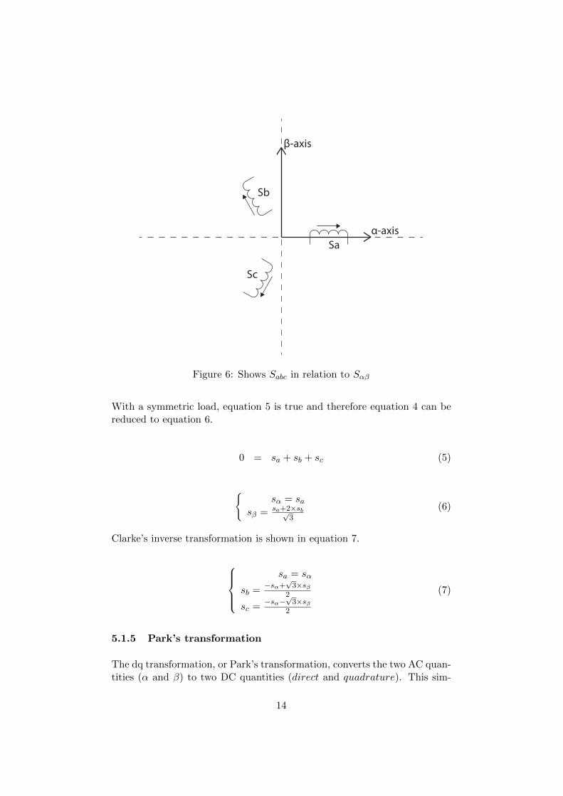
5.1.4 Clarke transformation
The αβ transformation, or the Clarke transformation, is used to simplifythe analysis of three-phase system using equation 4. Figure 6 shows how αand β corresponds to the three phases.
[7] [8]
sα = sa
sβ = sb−sc√3
(4)
13
α-axis
Sc
Sb
β-axis
Sa
Figure 6: Shows Sabc in relation to Sαβ
With a symmetric load, equation 5 is true and therefore equation 4 can bereduced to equation 6.
0 = sa + sb + sc (5)
sα = sa
sβ = sa+2×sb√3
(6)
Clarke’s inverse transformation is shown in equation 7.
sa = sα
sb =−sα+
√3×sβ
2
sc =−sα−
√3×sβ
2
(7)
5.1.5 Park’s transformation
The dq transformation, or Park’s transformation, converts the two AC quan-tities (α and β) to two DC quantities (direct and quadrature). This sim-
14
plifies the use of these quantities as feedback input to the regulators. Thed and q representation is achieved using equation 8 where θ is the electricalangle described in section 5.1.2 [7] [8].
sd = sα × cos(θ) + sβ × sin(θ)
sq = −sα × sin(θ) + sβ × cos(θ)(8)
Park’s inverse transformation is shown in equation 9.
sα = sd × cos(θ)− sq × sin(θ)sβ = sd × sin(θ) + sq × cos(θ)
(9)
5.1.6 d- and q-torque regulators
In the torque control loop the system regulates two DC quantities (d and q).There is one independent regulator for each quantity. The measured currentis transformed as described earlier and used as feedback. The d quantity isused to control the rotor flux linkage while the q quantity is used to controlthe torque. This project is only focused on controlling the motor torqueand therefore this system uses a static 0 reference for the d quantity. The qquantity however gets its reference from the throttle, for further details, seesection 6.3.
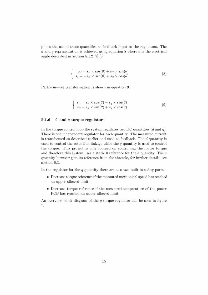
In the regulator for the q quantity there are also two built-in safety parts:
• Decrease torque reference if the measured mechanical speed has reachedan upper allowed limit.
• Decrease torque reference if the measured temperature of the powerPCB has reached an upper allowed limit.
An overview block diagram of the q-torque regulator can be seen in figure7.
15
Decrease Torque
Reference
Max Speed
Measured Speed
Torque Reference
Decrease Torque
Reference
PID
Measured Torque
Max Temp
Measured Temp
>=
YES
YES
>=
Figure 7: An overview of the q-torque regulator
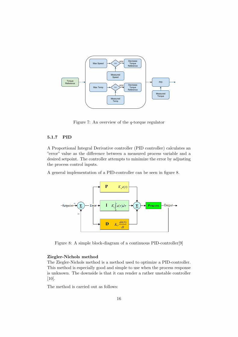
5.1.7 PID
A Proportional Integral Derivative controller (PID controller) calculates an”error” value as the difference between a measured process variable and adesired setpoint. The controller attempts to minimize the error by adjustingthe process control inputs.
A general implementation of a PID-controller can be seen in figure 8.
Figure 8: A simple block-diagram of a continuous PID-controller[9]
Ziegler-Nichols methodThe Ziegler-Nichols method is a method used to optimize a PID-controller.This method is especially good and simple to use when the process responseis unknown. The downside is that it can render a rather unstable controller[10].
The method is carried out as follows:
16

• Turn of the I- and D-parts, ie. set Ti =∞ and Td = 0.
• Set K0 to 0.
• Then increase K0 iteratively until the system begins to oscillate.
• Measure the period time T0 as in figure 9.
• Adjust the parameters according to table 1.
T0
Figure 9: Ziegler-Nichols
TypeParametersK Ti Td
P-type 0.5K0 − −PI-type 0.45K0 0.85T0 −PID-type 0.6K0 0.5T0 0.125T0
Table 1: Ziegler-Nichols
However Karl Johan Astrom and Tore Hagglund have shown that whenusing the same method, the parameters chosen in table 2 normally leads toa better stability [10]. Therefore the PID controllers were configured usingthis method.
TypeParametersK Ti Td
PID-type 0.35K0 0.77T0 0.19T0
Table 2: Astrom - Hagglund
17
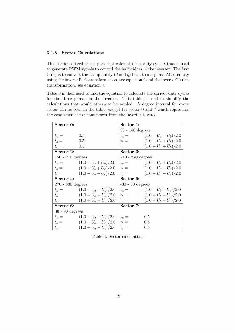
5.1.8 Sector Calculations
This section describes the part that calculates the duty cycle t that is usedto generate PWM signals to control the halfbridges in the inverter. The firstthing is to convert the DC quantity (d and q) back to a 3-phase AC quantityusing the inverse Park-transformation, see equation 9 and the inverse Clarke-transformation, see equation 7.
Table 8 is then used to find the equation to calculate the correct duty cyclesfor the three phases in the inverter. This table is used to simplify thecalculations that would otherwise be needed. A degree interval for everysector can be seen in the table, except for sector 0 and 7 which representsthe case when the output power from the inverter is zero.
Sector 0: Sector 1:90 - 150 degrees
ta = 0.5 ta = (1.0− Ua − Ub)/2.0tb = 0.5 tb = (1.0− Ua + Ub)/2.0tc = 0.5 tc = (1.0 + Ua + Ub)/2.0
Sector 2: Sector 3:150 - 210 degrees 210 - 270 degreesta = (1.0− Ub + Uc)/2.0 ta = (1.0 + Ua + Uc)/2.0tb = (1.0 + Ub + Uc)/2.0 tb = (1.0− Ua − Uc)/2.0tc = (1.0− Ub − Uc)/2.0 tc = (1.0 + Ua − Uc)/2.0Sector 4: Sector 5:270 - 330 degrees -30 - 30 degreesta = (1.0− Ua − Ub)/2.0 ta = (1.0− Ub + Uc)/2.0tb = (1.0− Ua + Ub)/2.0 tb = (1.0 + Ub + Uc)/2.0tc = (1.0 + Ua + Ub)/2.0 tc = (1.0− Ub − Uc)/2.0Sector 6: Sector 7:30 - 90 degreesta = (1.0 + Ua + Uc)/2.0 ta = 0.5tb = (1.0− Ua − Uc)/2.0 tb = 0.5tc = (1.0 + Ua − Uc)/2.0 tc = 0.5
Table 3: Sector calculations
18
0,00%
20,00%
40,00%
60,00%
80,00%
100,00%
0,00 30,00 60,00 90,00 120,00 150,00 180,00 210,00 240,00 270,00 300,00 330,00 360,00 390,00
Ta
Tb
Tc
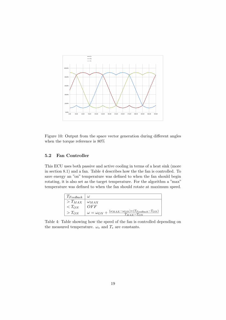
Figure 10: Output from the space vector generation during different angleswhen the torque reference is 80%
5.2 Fan Controller
This ECU uses both passive and active cooling in terms of a heat sink (morein section 8.1) and a fan. Table 4 describes how the the fan is controlled. Tosave energy an ”on” temperature was defined to when the fan should beginrotating, it is also set as the target temperature. For the algorithm a ”max”temperature was defined to when the fan should rotate at maximum speed.
TFeedback ω
> TMAX ωMAX
< TON OFF
> TON ω = ωON + (ωMAX−ωON )×(TFeedback−TON )TMAX−TON
Table 4: Table showing how the speed of the fan is controlled depending onthe measured temperature. ω∗ and T∗ are constants.
19
6 DSP and software specific to this project
This section describes the DSP used in this project and what applicationspecific software that has been constructed for this micro controller and thecustom PCB.
6.1 DSP - TMS320F28335
The DSP is a part of the Texas Instruments C2000 family and was providedby QRTECH. It has been chosen as a generic development platform becauseof its floating point acceleration and large range of integrated peripheralmodules (CAN, ADC, PWM etc.). The modules used in this project aredescribed in this section, but this DSP has a larger range of peripheralmodules built-in that can be used in different applications. This sectiongives a short description of the DSP that was used, further reading for moredetailed descriptions can be found in the datasheet [11].
ADC-moduleThis DSP has a built-in 12-bit ADC-core which can sample up to 12.5MSPS. It has 2 Sample/Hold circuits and 16 dedicated ADC channelswhere 8 channels can be multiplexed per Sample/Hold. It has an autosequencing capability that provides up to 16 ”auto-conversions” in asingle session. Each conversion can be programmed to select any ofthe 16 input channels. A session can either be triggered by softwareor the PWM-module.
CAN-moduleThe CAN module is fully compliant with CAN protocol, version 2.0Band supports data rates up to 1 Mbps. It also has 32 mailboxes withup to 8 bytes of data each.
GPIO-moduleThe device supports 88 GPIO pins, but all pins are multipurpose in thesense that they can support one or more peripheral modules as well.Two examples are that GPIO-0 also can be used as PWM channel 1-Aand GPIO-12 can also can be used as either Trip Zone-1 or CAN-Btransmit.
PWM-moduleThe PWM-module has 12 channels divided on 6 pairs, the system has 6dedicated Trip-zone signals to alert the module of external fault condi-tion. What happens when different trips occur can be configured indi-vidually for every pair of PWM-channels. The PWM-module can alsobe used to start internal interrupt sequences and ADC-conversions.
20
QEP-moduleThe quadrature encoder pulse (QEP) module is used for direct in-terface with a linear or rotary incremental encoder to get position,direction, and speed information from a rotating machine. In thisproject it takes two pulse trains (A and B) where every pulse repre-sent a fraction of the revolution, it combines this with a third pulsetrain (I) that ticks once every full revelation.
Real-Time JTAG and AnalysisThe device implements the standard IEEE 1149.1 JTAG interface
and supports real-time analysis whereby the contents of memory, pe-ripheral and register locations can be modified while the processor isrunning and executing code and servicing interrupts. The user can alsosingle step through non-time critical code while enabling time-criticalinterrupts to be serviced without interference. Additionally, it allowssetting of hardware breakpoint or data/address watch-points.
6.2 Electric Angle from pulsetrain
The signals from the IC-circuit described in section 7 is fed to the QEPmodule and then equation 10 is used where POSCNT is the current partiallength of an electric revolution in the PMSM, CPM is the total length of anelectric revolution, 2.0×π is to transform it into radian and calibratedAngleis the static phase shift between the PMSM and the Resolver. The QEP-module can be used in a number of ways to calculate the position count, inthis application the flanks of the A-pulse train triggers an up-count of thePOSCNT and the I-pulse train resets it to zero.
θ =2.0π × POSCNT
CPM+ calibratedAngle (10)
6.3 Torque Reference
This project uses a potentiometer for determining the torque reference andthis chapter will discuss the implementation of this. The ECU also hasbuilt-in functionality to be able to receive a torque reference from a Masterthrough CAN.
6.3.1 Potentiometer
To get a torque reference (τREF ) from the driver, two potentiometers areused, one for acceleration (AccRef) and one for the brakes (BrakeRef). To
21
ensure that the motor will not output a too high torque when the mechanicalbrake is applied, equation 11 is used to reduce the accelerator’s impact. Thereason for this is that one might otherwise burn power unnecessarily or burnthe windings in the motor. One aim here is that the brakes should have littleor no impact on the motor when a low force is applied and have an impactgrowth that is polynomiall, where the brakes will cut off the acceleratorwhen they are applied by 50%. AccRef and BrakeRef are normalizedvalues between 0.0 to 1.0.
τREF = (AccRef − 32×BrakeRef4)× τMAX (11)
6.4 Temperature measurement
The temperature measurement is done by a thermistor of a nonlinear NTC-type, the details of this can be found in the datasheet [12]. Because this isnonlinear, some kind of linearizion needed to be carried out for the DSP tobe able to convert the ADC-readout (x) to an approximated temperature.Two methods were considered, lookup-table and multiple equations for shortintervals. Look-up tables (LUT) lost because recalculating the ADC-readoutto an address that could be used with a LUT would be more complex thanto use the hardware acceleration for floating point multiplications in theDSP. And this renders it faster to use multiple equations with a switch andcase statement which is important since the calculation is executed duringthe interrupt-loop which has a given time frame. This resulted in 6 firstorder equations, see equation 12 and their results can be seen in table 5.The reason for multiplying with 4095 in equation 12 is that this equation iswritten so that it can easily be modified from taking normalized input from0.0 - 1.0 to the real ADC-readout where 1.0 is represented by 4095.
In table 5, the deviation from the real temperature to the calculated oneis always less then 1C, these equations were auto generated and the effortto produce these 6 equations were therefore negligible. These precise valuesare not of a great importance when controlling the fan, but the values aresupposed to be presented to the driver and used for future development andoptimizations, and thus the seemingly unnecessary precision.
t =
−0.0256× 4095× x+ 103.82, 1.000 >= x > 0.828−0.0213× 4095× x+ 90.263, 0.828 >= x > 0.493−0.0253× 4095× x+ 98.389, 0.493 >= x > 0.308−0.0377× 4095× x+ 114.83, 0.308 >= x > 0.211−0.0627× 4095× x+ 135.11, 0.211 >= x > 0.128−0.1083× 4095× x+ 157.63, 0.128 >= x >= 0.000
(12)
22

real (C) aprox. (C) real (C) aprox. (C)
10,00 9,66 70,00 70,3115,00 14,42 75,00 75,5520,00 20,27 80,00 80,2225,00 25,00 85,00 84,3930,00 29,94 90,00 90,4035,00 34,99 95,00 95,6740,00 40,04 100,00 100,3145,00 44,58 105,00 104,3550,00 50,14 110,00 110,4155,00 55,35 115,00 115,6160,00 60,16 120,00 120,2765,00 64,54 125,00 124,27
Table 5: Real values and their respective approximated values from themodel used.
23
7 Hardware
In this section the inverter hardware and its components will be discussed.At first a brief overview of the system will be presented and then the functionwill be described. The most relevant and active component choices made inthis project will be discussed and motivated here and the physical solutionwith layout will be discussed. Throughout this chapter it is valuable to havethe schematics for the two parts of the system at hand. The schematics,together with drawings of the layouts, can be found in appendix A and B.
7.1 Hardware overview
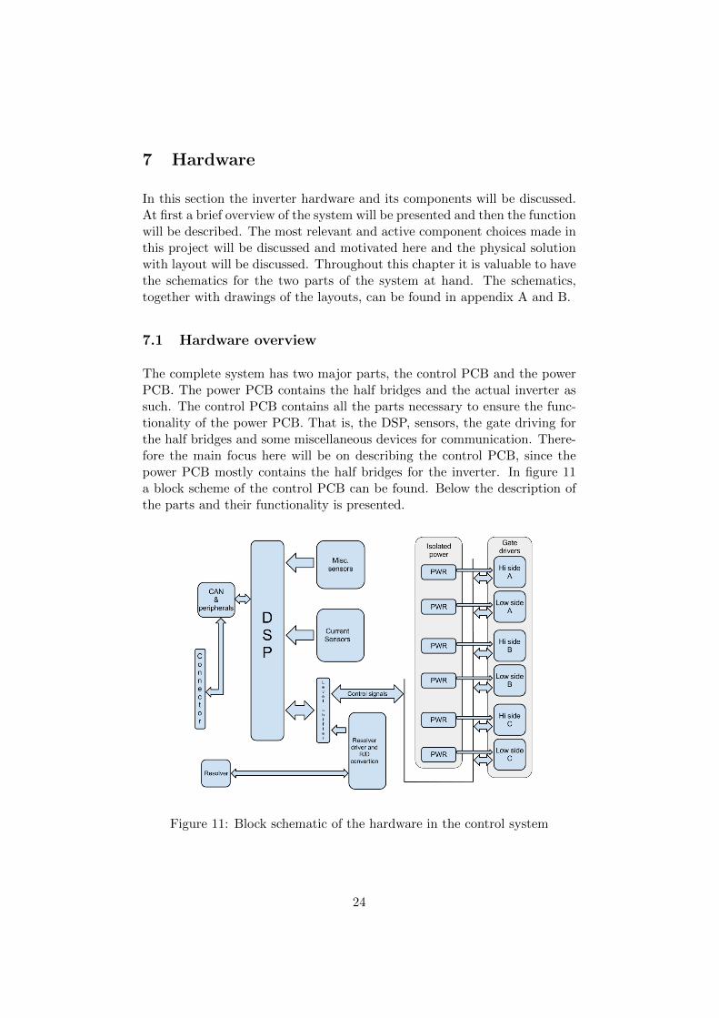
The complete system has two major parts, the control PCB and the powerPCB. The power PCB contains the half bridges and the actual inverter assuch. The control PCB contains all the parts necessary to ensure the func-tionality of the power PCB. That is, the DSP, sensors, the gate driving forthe half bridges and some miscellaneous devices for communication. There-fore the main focus here will be on describing the control PCB, since thepower PCB mostly contains the half bridges for the inverter. In figure 11a block scheme of the control PCB can be found. Below the description ofthe parts and their functionality is presented.
Figure 11: Block schematic of the hardware in the control system
24
7.2 Description of the system blocks
Here a more in-depth description of the system blocks can be found. Thegeneral function is described for each of the blocks and the design is dis-cussed. For reference see the schematics in appendix A and B.
7.2.1 CAN & peripherals
In this block the CAN controller and some outputs for peripheral indicatorLEDs are found. CAN is implemented with a basic CAN transceiver andsome ESD protection on the bus terminals. The CAN transceiver is thendirectly connected to the on-board CAN controller in the DSP. The outputsfor the indicator LEDs are driven by small MOSFETs in series with a currentlimiting resistor. The outputs are connected to the cathode of standardLEDs.
7.2.2 Current sensors, resolver and miscellaneous sensors
On the control PCB some different sensors are implemented. The mostprominent ones on the PCB are the three current sensors that measure thecurrent output to each of the three phases. These are operation criticaland are hall-effect type current sensors from LEM that can measure upto 300A. The sensors outputs a voltage directly proportional to the currentflowing though the sensor. Since the sensors are supplied with 5V the outputranges from 0 to +5V. The DSP can only handle +3.3V on the ADC inputsthough, this is sorted by a simple resistive voltage divider. This could havebeen solved with a op-amp instead, which would have been a much moreproper solution, however this would have required too much time to develop.Therefore the simple solution was preferred. The sensors also have simpleRC-low pass filters on the outputs to reduce the high frequency noise on thesignal to the DSP.
The other operation crucial sensor is the angle sensor mounted on the mo-tor. This sensor is a resolver type sensor, and the sensor itself is describedin detail in section 8.4. This sensor measures the angle of the motor driveshaft in electrical RPM. This means that the output angle from the sensor isdirectly coupled to the current flowing through the motors windings. Boththe motor and the resolver sensor thus have four electrical revolutions permechanical revolution. The resolver requires a driving and conversion cir-cuit, which drives the primary side of the resolver and converts the outputsfrom the resolver sensor to either a 12bit binary number or to two pulsetrains and an index pulse, equivalent to the outputs of an encoder. In thisproject the encoder equivalent outputs were chosen since the DSP has an
25
integrated module to decode such an input to an angle. This also reducesthe number of I/O lines required on the DSP. The R/D converter IC alsooutputs the sine and cosine waveforms and these are also connected to theADC unit in the DSP via a resistive voltage divider. This was done to enablethe future development of a software R/D converter, however this is not inthe scope of this project.
On the power PCB there are two types of temperature sensors. Firstlythere is an NTC resistor to measure the actual temperature of the powerPCB and the heat sink. Secondly, there is also a series of PTC-resistors, withone resistor for each half bridge. These are used to disable the inverter viahardware shutdown functions to prevent damage due to overheating. Thechain of PTC-resistors is connected to an op-amp based comparator witha small window of hysteresis. The output of the comparator is connectedto the hardware shutdown on all of the gate drivers and to a GPIO on theDSP to indicate normal operating temperature. The same signal is also, viaa small transistor, connected to the DPS’s shutdown signal, to enable thesoftware to utilize the hardware shutdown on the drivers.
7.2.3 Gate drivers
Each phase has a set of gate drivers which drive the gates of the MOS-FETs in the bridge. Since this inverter needs to be able to handle largeamounts of current, there is a demand for low resistive losses and abilityfor fast switching of the transistors. This set of demands makes P-channelMOSFETs undesirable since they have much lower charge carrier mobilityand thus need to be a lot bigger to compensate this and meet the currentrequirement. This in turn leads to an equal increase in gate capacitance.However, the N-channel device needs a positive gate-source voltage to beturned on, and this is the reason for the use of galvanically isolated gatedrivers.
The gate drivers used for this design are the Infineon 1ed020i12-f isolateddrivers. These gate drivers were prechosen to this project by QRTECH.Each gate driver drives one side (upper or lower side) of each phase, thusthere are are two drivers per phase and six drivers in total in the design.Input to the drivers are isolated power, and control signals. Among thecontrols signals there are two PWM signals, one for the upper half and onefor the lower half of the phase, i.e. the two drivers in each phase receive thePWM signals for both the upper and the lower half of the phase that theyare driving. This is done because built in to the drivers is a safety featurethat by the use of both PWM signals ensures that both half’s of a bridgeis never in on state at the same time and thus preventing shoot throughcurrents. A shutdown or reset input is also available which turns off the
26
driver output. This is used either by the software or by the temperatureprotection to shut down all the gate drivers if needed.
On the output side of the drivers there are small driving bridges, that con-sists of a pair of npn/pnp bipolar transistors, two for each half bridge (seeschematics in appendix A for details). By this design the gate drivers onlyhave to drive a signal to the final small bridges that do the actual drivingof the MOSFETs gates. Although the drivers are specified to drive 2A railto rail[13], these small final bridges were implemented. When this is donethe driver only needs to drive the output to signal strength, and the actualdrive current to the gates are delivered by the final small npn/pnp bridges.This design offers very high noise immunity since the drivers can drive theiroutput very hard. The final small bridges also have a small filtering of thepower supplied to the bipolar transistors with a 100Ω resistor and a 1µFcapacitor. Since the gates are more or less a capacitor that is charged toturn the MOSFET on, the large capacitor and the resistor smooths out thecurrent spikes that otherwise would appear on the supply lines to the smallbridges. This is desirable since it reduces noise emissions.
7.2.4 Isolated power
The gate drivers need a galvanically isolated power supply to drive the MOS-FETs. The power is supplied by Traco isolated power modules that outputgalvanically isolated 24V. This is then divided with zener diodes to give a+15V, -8V and a GND reference. By dividing the isolated voltage the gatesof the MOSFETs can be driven to voltages that ensure safe and reliableoperation. By driving the gates to -8V in off state, the possibility of thetransistor being turned on from over heard noise to the gate, or by parasiticcapacitances is greatly reduced.
7.2.5 Half brigdes
The half bridges are the main part of the inverter it self, see schematicsin appendix B. They mainly consist of a pair of MOSFETs connected inseries between the poles of the battery supply. The output phase voltage isconnected in between the two transistors. Parallel to each of the transistorssnubber circuits are connected. The snubber is a RC-circuit used to dampenovershoots that occur from the parasitic inductance in the tracks on thepower PCB. The snubber is further discussed in section 7.3.4. In parallelwith both the transistors is the reverse recovery capacitor connected, this isalso discussed in detail in section 7.3.3. To the gate of each MOSFET thereis a protection diode connected to protect the transistor from a too highgate voltage. There is also a small transistor connected between the gate
27
and the source on the large MOS devices. This transistor is there to ensurethat the gate of the large MOSFET is kept low when the device is turnedoff and does not get turned on by parasitic capacitances or other noise. Thesignals to control this are connected to the control PCB via a 6 way pinheader.
7.3 Component choices
In this section the major important component choices are discussed in de-tail. Many of all the components used in the whole design are not discussedhere since many are considered self explanatory, such as pull up/down re-sistors and decoupling capacitors. Those components of interest are moreof a crucial nature to the design and have been changed from the originaldesign to fit the new specification. Note that the whole design is mostlycarried over from a previous similar project with another set of demands onvoltages and currents and thus most of the design choices were not made inthis project.
7.3.1 Traco power modules
To supply the isolated gate drivers with galvanically isolated power, Tracopower modules were chosen. In the original design, this isolated power wassupplied via switch transformers controlled by the DSP. This solution neededsome rework to handle the increase in power demand when redesigning fromIGBTs to MOSFETs used in this project, since the IGBTs from previousdesign has a much lower gate charge than the MOSFETs and there werefewer of them. Thus the demand for current is increased. However due totime constraints and a desire to simply avoid problems arising from thesepower supplies a complete off the shelf solution was chosen. The modulestake an input voltage of 36-72V and outputs an galvanically isolated 24V,125mA.
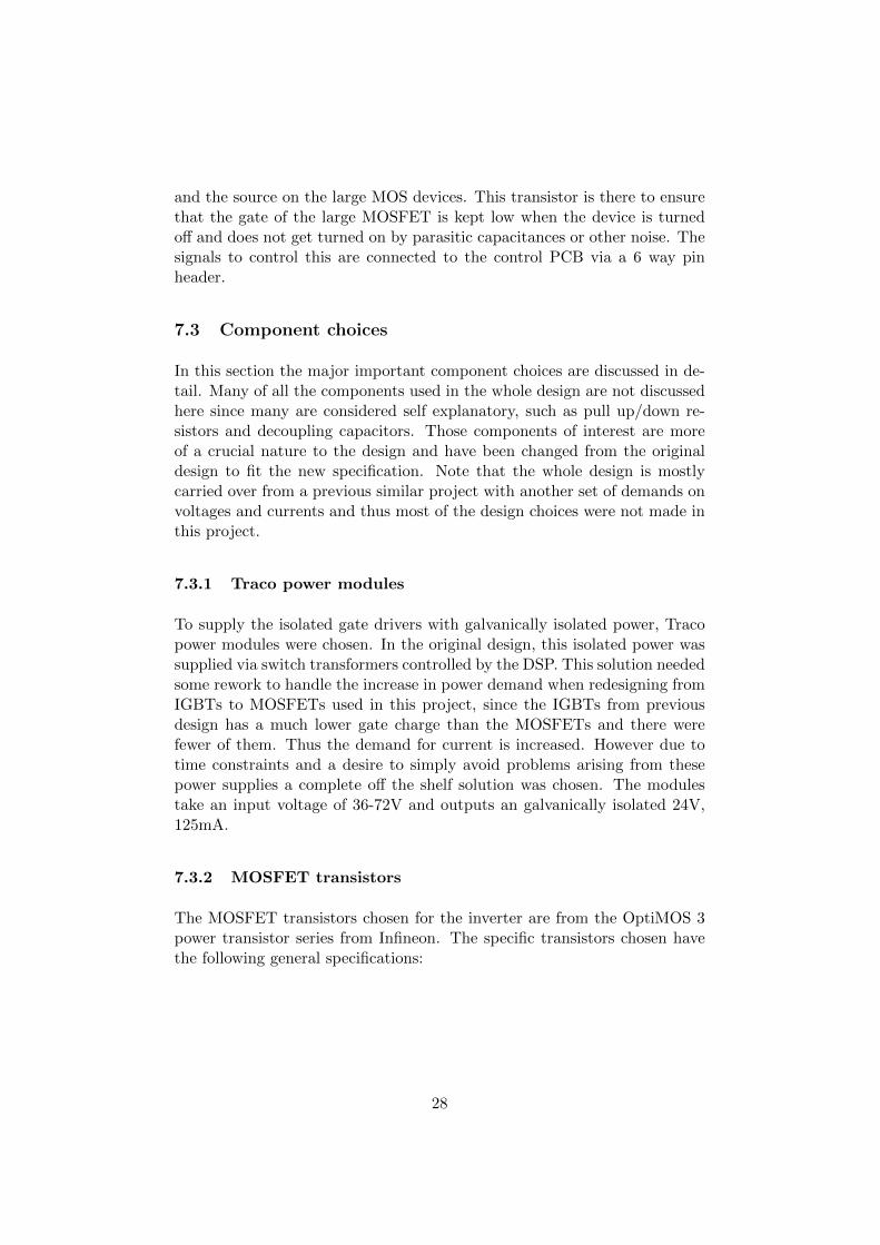
7.3.2 MOSFET transistors
The MOSFET transistors chosen for the inverter are from the OptiMOS 3power transistor series from Infineon. The specific transistors chosen havethe following general specifications:
28
Description: value:
VDS 100V
RDS(on),max 2.5mΩ
ID 180A
Table 6: Basic properties of the MOS-transistors
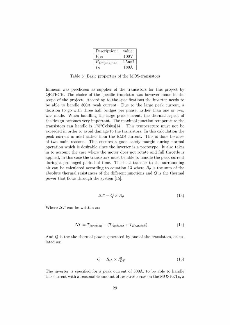
Infineon was prechosen as supplier of the transistors for this project byQRTECH. The choice of the specific transistor was however made in thescope of the project. According to the specifications the inverter needs tobe able to handle 300A peak current. Due to the large peak current, adecision to go with three half bridges per phase, rather than one or two,was made. When handling the large peak current, the thermal aspect ofthe design becomes very important. The maximal junction temperature thetransistors can handle is 175Celsius[14]. This temperature must not beexceeded in order to avoid damage to the transistors. In this calculation thepeak current is used rather than the RMS current. This is done becauseof two main reasons. This ensures a good safety margin during normaloperation which is desirable since the inverter is a prototype. It also takesin to account the case where the motor does not rotate and full throttle isapplied, in this case the transistors must be able to handle the peak currentduring a prolonged period of time. The heat transfer to the surroundingair can be calculated according to equation 13 where Rθ is the sum of theabsolute thermal resistances of the different junctions and Q is the thermalpower that flows through the system [15].
∆T = Q×Rθ (13)
Where ∆T can be written as:
∆T = Tjunction − (TAmbient + THeatsink) (14)
And Q is the the thermal power generated by one of the transistors, calcu-lated as:
Q = Rch × I2DS (15)
The inverter is specified for a peak current of 300A, to be able to handlethis current with a reasonable amount of resistive losses on the MOSFETs, a
29
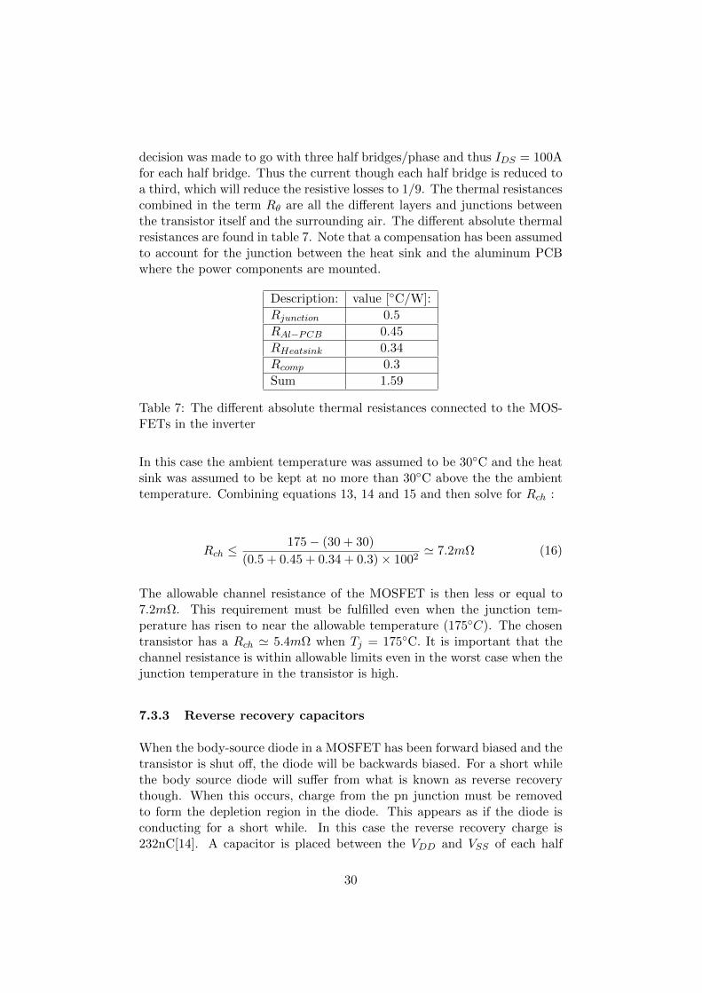
decision was made to go with three half bridges/phase and thus IDS = 100Afor each half bridge. Thus the current though each half bridge is reduced toa third, which will reduce the resistive losses to 1/9. The thermal resistancescombined in the term Rθ are all the different layers and junctions betweenthe transistor itself and the surrounding air. The different absolute thermalresistances are found in table 7. Note that a compensation has been assumedto account for the junction between the heat sink and the aluminum PCBwhere the power components are mounted.
Description: value [C/W]:
Rjunction 0.5
RAl−PCB 0.45
RHeatsink 0.34
Rcomp 0.3
Sum 1.59
Table 7: The different absolute thermal resistances connected to the MOS-FETs in the inverter
In this case the ambient temperature was assumed to be 30C and the heatsink was assumed to be kept at no more than 30C above the the ambienttemperature. Combining equations 13, 14 and 15 and then solve for Rch :
Rch ≤175− (30 + 30)
(0.5 + 0.45 + 0.34 + 0.3)× 1002' 7.2mΩ (16)
The allowable channel resistance of the MOSFET is then less or equal to7.2mΩ. This requirement must be fulfilled even when the junction tem-perature has risen to near the allowable temperature (175C). The chosentransistor has a Rch ' 5.4mΩ when Tj = 175C. It is important that thechannel resistance is within allowable limits even in the worst case when thejunction temperature in the transistor is high.
7.3.3 Reverse recovery capacitors
When the body-source diode in a MOSFET has been forward biased and thetransistor is shut off, the diode will be backwards biased. For a short whilethe body source diode will suffer from what is known as reverse recoverythough. When this occurs, charge from the pn junction must be removedto form the depletion region in the diode. This appears as if the diode isconducting for a short while. In this case the reverse recovery charge is232nC[14]. A capacitor is placed between the VDD and VSS of each half
30
bridge, as close as possible to the transistors, to handle this charge. Thecapacitor must be a ceramic or plastic, since the the course of the reverserecovery is in the order of 10th of nano seconds. The chosen capacitor is ofX7R-type dielectric. The accepted voltage ripple over this capacitor whenthis charge flows in and out of the capacitor was set to 0.05V. The requiredcapacitance to achieve this is then:
C =Q
V=
232nC
0.05V' 4.7µF (17)
In the inverter two of these capacitors have been stacked for double thecapacitance. This was done to further decrease the amplitude of the rippleon the VSS and VDD rails to the half bridges.
7.3.4 Snubber circuit
The ”snubber” is a RC-link placed parallel to each MOS-transistor in all thehalf bridges. The snubber circuit is there to handle the voltage overshootthat occurs when the MOS-transistors are turned off. This overshoot occursdue to the stray inductance, that comes from the cables and the tracks onthe power PCB and such, which tries to continue driving the current thoughthe transistor when it is quickly turned off.
As a rule of thumb, a RC-snubber for a MOSFET can be designed with a ca-pacitance twice the output capacitance of the transistor. The resistor valueis determined by measuring the frequency of the oscillations on the over-shoot, and then fitting the cutoff frequency of the RC-link to the frequencyof the oscillations. In this design however, the capacitance was chosen tobe able to handle as much energy as possible to minimize the peak voltageof the overshoot, and was therefore chosen to 22nF, since these capacitorswere already available.
To decide the resistor value in the RC-link, the max current though the tran-sistor was considered. When driving the max allowed 100A, and abruptlyshutting off the transistor, the current will continue flowing for a short while.This current will flow through to the capacitor, and since the capacitor isconducting like this, basically the whole voltage drop will end up over theresistors. This voltage is simply derived from ohm’s model in equation 18.
U = R× I (18)
The voltage over the resistor needs to be sufficiently low to not break theresistor. The accepted voltage over the resistor was decided to be less than
31
100V but the resistor can not be too small since this would cause unneces-sarily large amounts of energy being wasted as heat. Therefore after somediscussions the resistance was chosen to 0.68Ω. This will give a voltage of68V when 100A flows through the snubber, which was deemed as acceptable.
7.4 PCB Layout
In this section the configuration of the PCBs and layout of both of the PCBswill be discussed. Some special considerations and component placement willbe discussed. The section is divided into one chapter per PCB. The inverterPCBs are divided in to a power PCB where the half bridges are mountedand a control PCB where the DSP and the gate drivers are mounted.
7.4.1 Power PCB
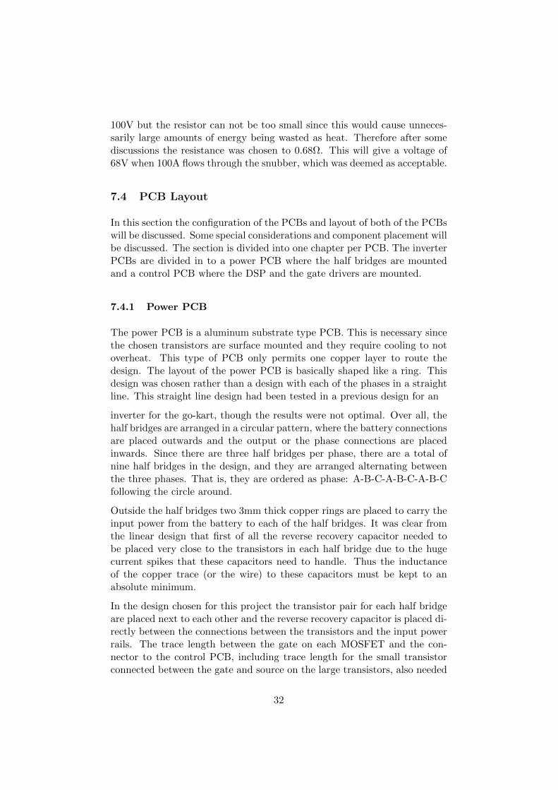
The power PCB is a aluminum substrate type PCB. This is necessary sincethe chosen transistors are surface mounted and they require cooling to notoverheat. This type of PCB only permits one copper layer to route thedesign. The layout of the power PCB is basically shaped like a ring. Thisdesign was chosen rather than a design with each of the phases in a straightline. This straight line design had been tested in a previous design for an
inverter for the go-kart, though the results were not optimal. Over all, thehalf bridges are arranged in a circular pattern, where the battery connectionsare placed outwards and the output or the phase connections are placedinwards. Since there are three half bridges per phase, there are a total ofnine half bridges in the design, and they are arranged alternating betweenthe three phases. That is, they are ordered as phase: A-B-C-A-B-C-A-B-Cfollowing the circle around.
Outside the half bridges two 3mm thick copper rings are placed to carry theinput power from the battery to each of the half bridges. It was clear fromthe linear design that first of all the reverse recovery capacitor needed tobe placed very close to the transistors in each half bridge due to the hugecurrent spikes that these capacitors need to handle. Thus the inductanceof the copper trace (or the wire) to these capacitors must be kept to anabsolute minimum.
In the design chosen for this project the transistor pair for each half bridgeare placed next to each other and the reverse recovery capacitor is placed di-rectly between the connections between the transistors and the input powerrails. The trace length between the gate on each MOSFET and the con-nector to the control PCB, including trace length for the small transistorconnected between the gate and source on the large transistors, also needed
32
special care. These traces need to be as short as possible to have as lowimpedance as possible and to avoid picking up too much noise, which couldlead to potentially driving a transistor to a faulty state.
The old linear design also had a large input capacitor for some currentbuffering, though it had become apparent that the trace length from thehalf bridges out to the large capacitor was too great. With this in mind alarge number of smaller aluminum electrolytic capacitors were placed on thecopper rings. This enabled the capacitance to still be quite large and yet bedistributed over all the half bridges, and thus the trace length to the bridgesis minimized.
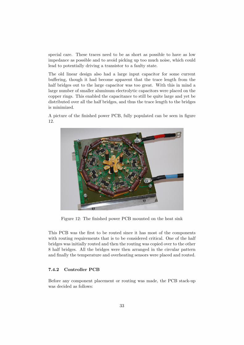
A picture of the finished power PCB, fully populated can be seen in figure12.
Figure 12: The finished power PCB mounted on the heat sink
This PCB was the first to be routed since it has most of the componentswith routing requirements that is to be considered critical. One of the halfbridges was initially routed and then the routing was copied over to the other8 half bridges. All the bridges were then arranged in the circular patternand finally the temperature and overheating sensors were placed and routed.
7.4.2 Controller PCB
Before any component placement or routing was made, the PCB stack-upwas decided as follows:
33
• 6 layers should be used. This was preferred to save time spent routingcompared to a 4 layer board
• All components must be placed on the top layer, with exception to theconnectors connecting the control and power PCB together
• The outer top and bottom layers should only have local signal routing,especially the bottom layer, to ensure good noise immunity
• Internal layers will be 3 signal layers and one layer reserved for powerplanes
Since the power PCB was routed prior to the any routing being done on thecontrol PCB, the pin headers connecting the two cards together could beplaced on the bottom side and locked in position first on the control PCB.The remaining routing was done with these headers as a first premise.
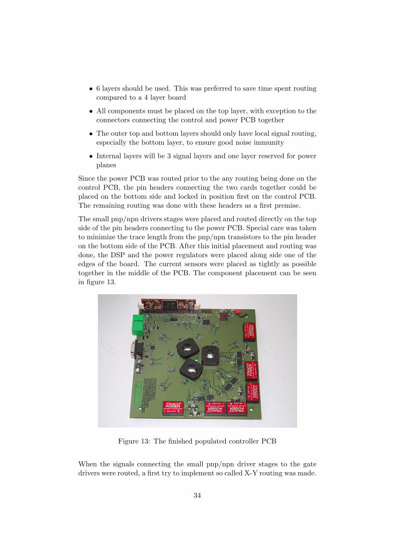
The small pnp/npn drivers stages were placed and routed directly on the topside of the pin headers connecting to the power PCB. Special care was takento minimize the trace length from the pnp/npn transistors to the pin headeron the bottom side of the PCB. After this initial placement and routing wasdone, the DSP and the power regulators were placed along side one of theedges of the board. The current sensors were placed as tightly as possibletogether in the middle of the PCB. The component placement can be seenin figure 13.
Figure 13: The finished populated controller PCB
When the signals connecting the small pnp/npn driver stages to the gatedrivers were routed, a first try to implement so called X-Y routing was made.
34
X-Y routing means that designated layers are used for routing strictly in Xor Y direction of the PCB only, and is used to minimize EMI problems.
However, it became apparent due to the layout of the pin headers, i.e. thering-shape and the order of the phases as described earlier, made this routingstyle very inconvenient. Therefore a solution based on the ring shape usedon the power PCB was used where open rings with all the 6 signals/isolatedpower lines were routed in parallel and the different phases were stacked onindividual layers in the PCB. These rings can clearly be seen in the compositedrawing of the control PCB in appendix A. The rings were orientated to leavethe opening facing the DSP and the level shifter so the signal traces fromthe current sensors could be routed.
The gate driver circuits were placed on the opposite side of the circle openingto equalize the trace lenght to the small driver stages. The Traco powermodules were placed last and were merely placed along side the edges ofthe PCB that were closest to the gate drivers. A composite drawing of therouting on the different layers can be found in appendix A.
35
8 Building and intregrating a powertrain on a Go-Kart
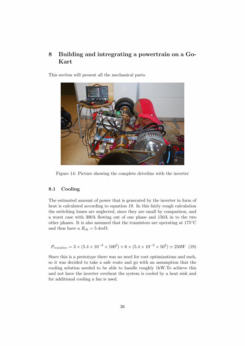
This section will present all the mechanical parts.
Figure 14: Picture showing the complete driveline with the inverter
8.1 Cooling
The estimated amount of power that is generated by the inverter in form ofheat is calculated according to equation 19. In this fairly rough calculationthe switching losses are neglected, since they are small by comparison, anda worst case with 300A flowing out of one phase and 150A in to the twoother phases. It is also assumed that the transistors are operating at 175Cand thus have a Rch = 5.4mΩ.
Presistive = 3× (5.4× 10−3 × 1002) + 6× (5.4× 10−3 × 502) ' 250W (19)
Since this is a prototype there was no need for cost optimizations and such,so it was decided to take a safe route and go with an assumption that thecooling solution needed to be able to handle roughly 1kW.To achieve thisand not have the inverter overheat the system is cooled by a heat sink andfor additional cooling a fan is used.
36
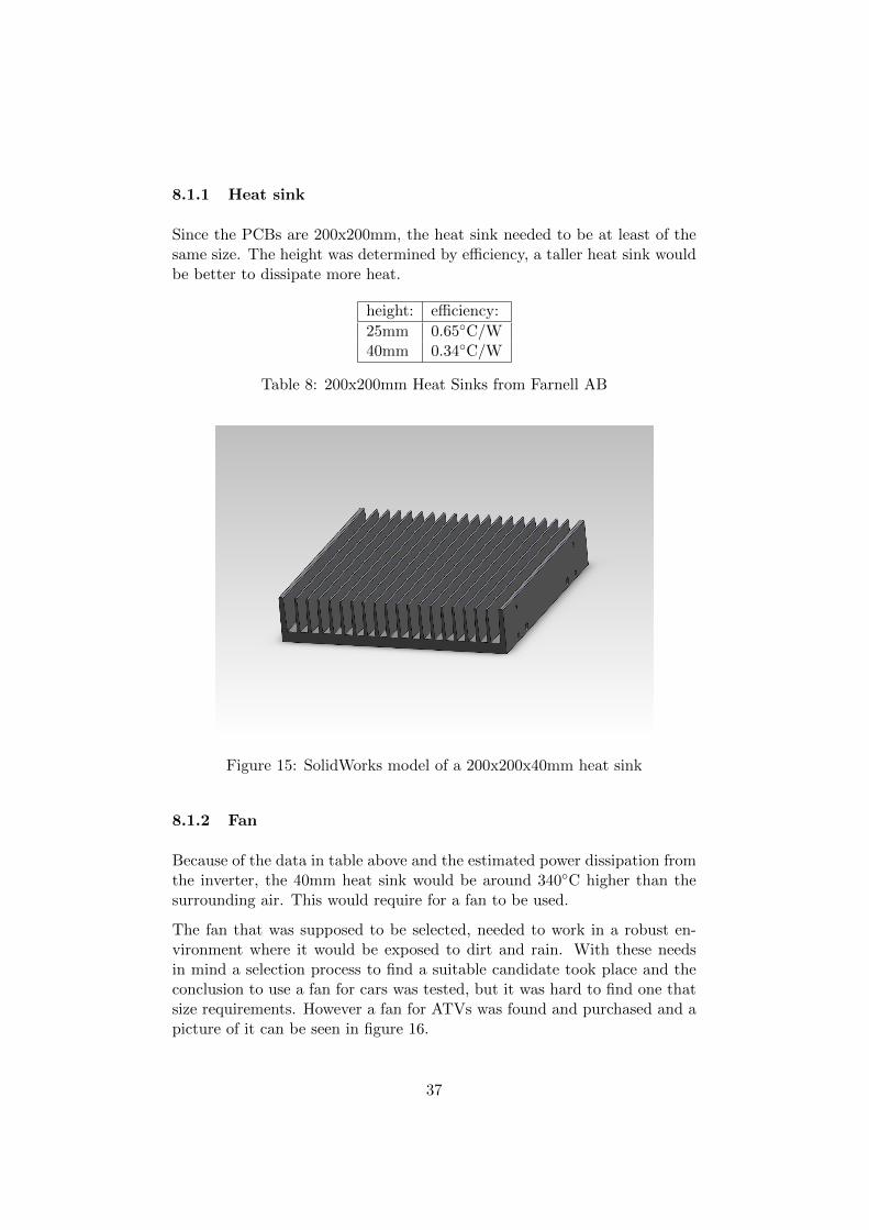
8.1.1 Heat sink
Since the PCBs are 200x200mm, the heat sink needed to be at least of thesame size. The height was determined by efficiency, a taller heat sink wouldbe better to dissipate more heat.
height: efficiency:
25mm 0.65C/W40mm 0.34C/W
Table 8: 200x200mm Heat Sinks from Farnell AB
Figure 15: SolidWorks model of a 200x200x40mm heat sink
8.1.2 Fan
Because of the data in table above and the estimated power dissipation fromthe inverter, the 40mm heat sink would be around 340C higher than thesurrounding air. This would require for a fan to be used.
The fan that was supposed to be selected, needed to work in a robust en-vironment where it would be exposed to dirt and rain. With these needsin mind a selection process to find a suitable candidate took place and theconclusion to use a fan for cars was tested, but it was hard to find one thatsize requirements. However a fan for ATVs was found and purchased and apicture of it can be seen in figure 16.
37
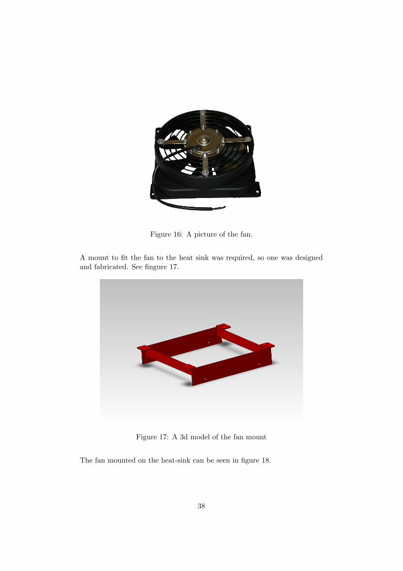
Figure 16: A picture of the fan.
A mount to fit the fan to the heat sink was required, so one was designedand fabricated. See fingure 17.
Figure 17: A 3d model of the fan mount
The fan mounted on the heat-sink can be seen in figure 18.
38
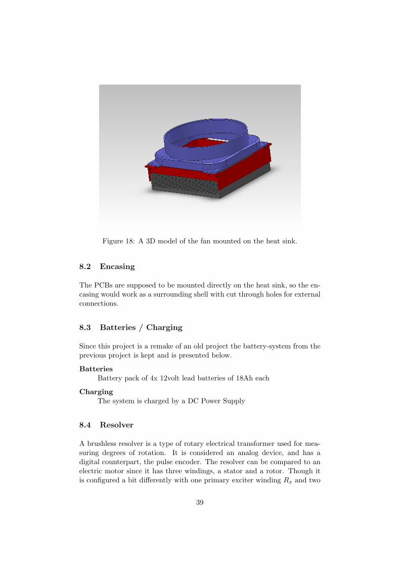
Figure 18: A 3D model of the fan mounted on the heat sink.
8.2 Encasing
The PCBs are supposed to be mounted directly on the heat sink, so the en-casing would work as a surrounding shell with cut through holes for externalconnections.
8.3 Batteries / Charging
Since this project is a remake of an old project the battery-system from theprevious project is kept and is presented below.
BatteriesBattery pack of 4x 12volt lead batteries of 18Ah each
ChargingThe system is charged by a DC Power Supply
8.4 Resolver
A brushless resolver is a type of rotary electrical transformer used for mea-suring degrees of rotation. It is considered an analog device, and has adigital counterpart, the pulse encoder. The resolver can be compared to anelectric motor since it has three windings, a stator and a rotor. Though itis configured a bit differently with one primary exciter winding Rx and two
39
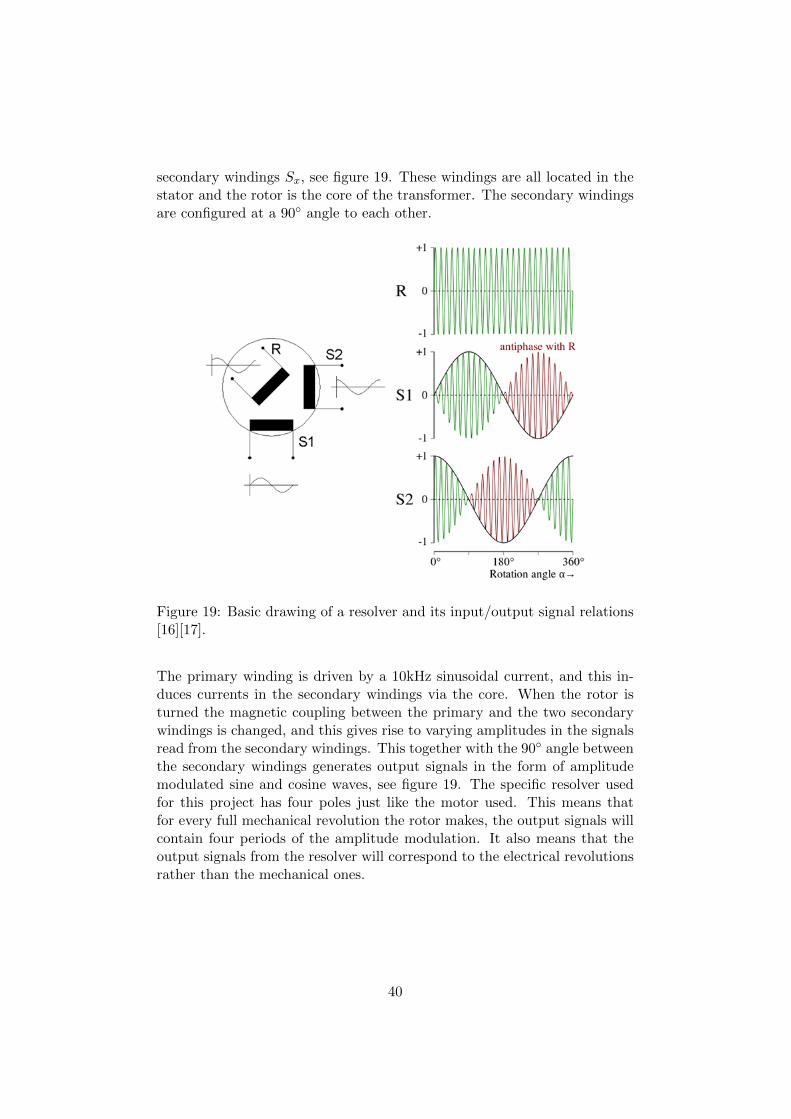
secondary windings Sx, see figure 19. These windings are all located in thestator and the rotor is the core of the transformer. The secondary windingsare configured at a 90 angle to each other.
Figure 19: Basic drawing of a resolver and its input/output signal relations[16][17].
The primary winding is driven by a 10kHz sinusoidal current, and this in-duces currents in the secondary windings via the core. When the rotor isturned the magnetic coupling between the primary and the two secondarywindings is changed, and this gives rise to varying amplitudes in the signalsread from the secondary windings. This together with the 90 angle betweenthe secondary windings generates output signals in the form of amplitudemodulated sine and cosine waves, see figure 19. The specific resolver usedfor this project has four poles just like the motor used. This means thatfor every full mechanical revolution the rotor makes, the output signals willcontain four periods of the amplitude modulation. It also means that theoutput signals from the resolver will correspond to the electrical revolutionsrather than the mechanical ones.
40
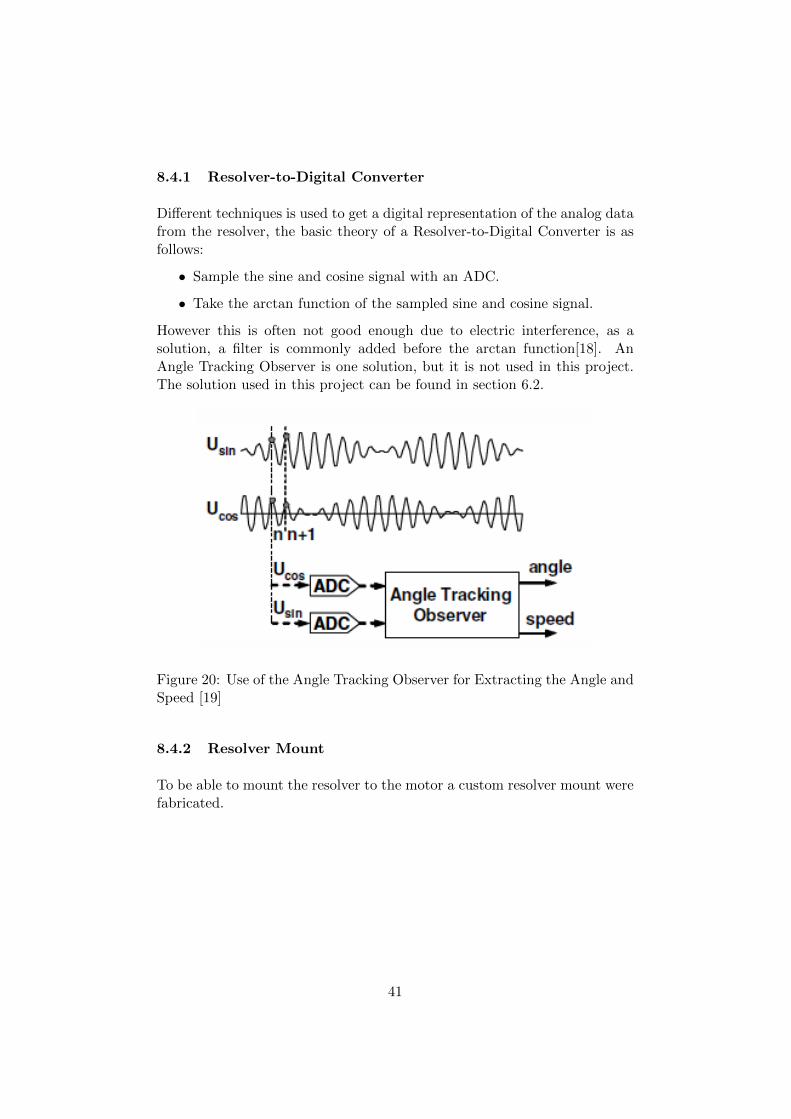
8.4.1 Resolver-to-Digital Converter
Different techniques is used to get a digital representation of the analog datafrom the resolver, the basic theory of a Resolver-to-Digital Converter is asfollows:
• Sample the sine and cosine signal with an ADC.
• Take the arctan function of the sampled sine and cosine signal.
However this is often not good enough due to electric interference, as asolution, a filter is commonly added before the arctan function[18]. AnAngle Tracking Observer is one solution, but it is not used in this project.The solution used in this project can be found in section 6.2.
Figure 20: Use of the Angle Tracking Observer for Extracting the Angle andSpeed [19]
8.4.2 Resolver Mount
To be able to mount the resolver to the motor a custom resolver mount werefabricated.
41

Figure 21: SolidWorks model of the resolver mount
Resolver Shield For the resolver to be protected from stone chips and dirta shield was fabricated.
Figure 22: SolidWorks model of the resolver shield
Resolver Rotor The rotor bought to the resolver needs an adapter to fitaround the motors drive shaft. This was fabricated and it also needed somespacers so that the rotor could be fixed between two washers.
42
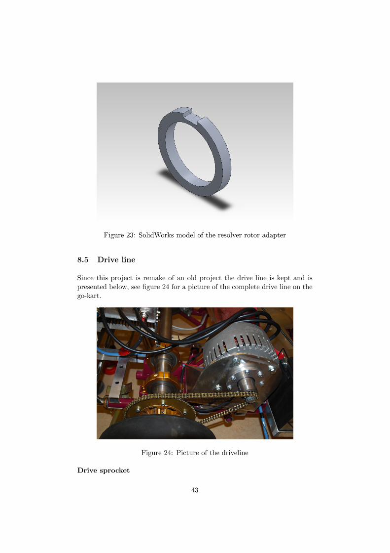
Figure 23: SolidWorks model of the resolver rotor adapter
8.5 Drive line
Since this project is remake of an old project the drive line is kept and ispresented below, see figure 24 for a picture of the complete drive line on thego-kart.
Figure 24: Picture of the driveline
Drive sprocket
43
The engine axle is not of a go-kart-standard an adapter is used to drivea drive sprocket. The drive-sprocket used has 13 teeth.
Driven sprocketThe driven sprocket is of a standard go-kart size and has 70 teeth.
Roller chainThe roller chain is a go-kart chain
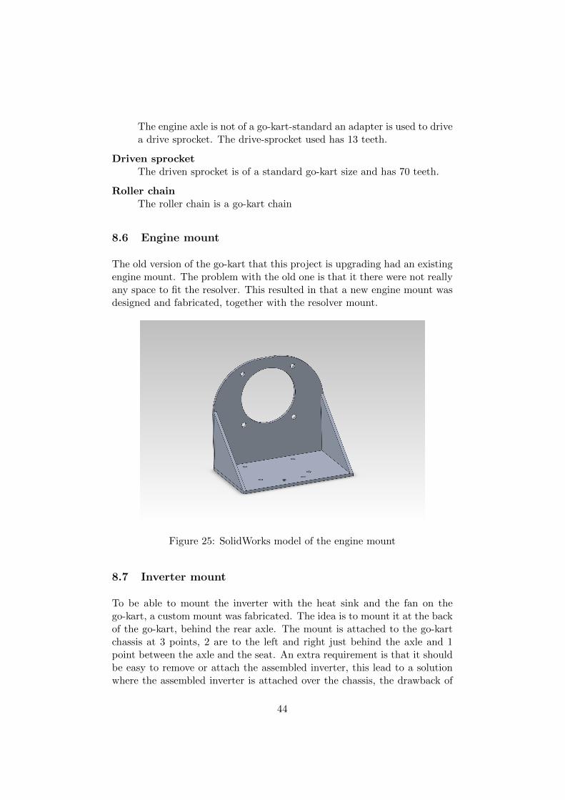
8.6 Engine mount
The old version of the go-kart that this project is upgrading had an existingengine mount. The problem with the old one is that it there were not reallyany space to fit the resolver. This resulted in that a new engine mount wasdesigned and fabricated, together with the resolver mount.
Figure 25: SolidWorks model of the engine mount
8.7 Inverter mount
To be able to mount the inverter with the heat sink and the fan on thego-kart, a custom mount was fabricated. The idea is to mount it at the backof the go-kart, behind the rear axle. The mount is attached to the go-kartchassis at 3 points, 2 are to the left and right just behind the axle and 1point between the axle and the seat. An extra requirement is that it shouldbe easy to remove or attach the assembled inverter, this lead to a solutionwhere the assembled inverter is attached over the chassis, the drawback of
44
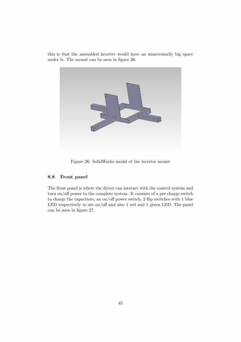
this is that the assembled inverter would have an unnecessarily big spaceunder it. The mount can be seen in figure 26.
Figure 26: SolidWorks model of the inverter mount
8.8 Front panel
The front panel is where the driver can interact with the control system andturn on/off power to the complete system. It consists of a pre-charge switchto charge the capacitors, an on/off power switch, 2 flip switches with 1 blueLED respectively to see on/off and also 1 red and 1 green LED. The panelcan be seen in figure 27.
45
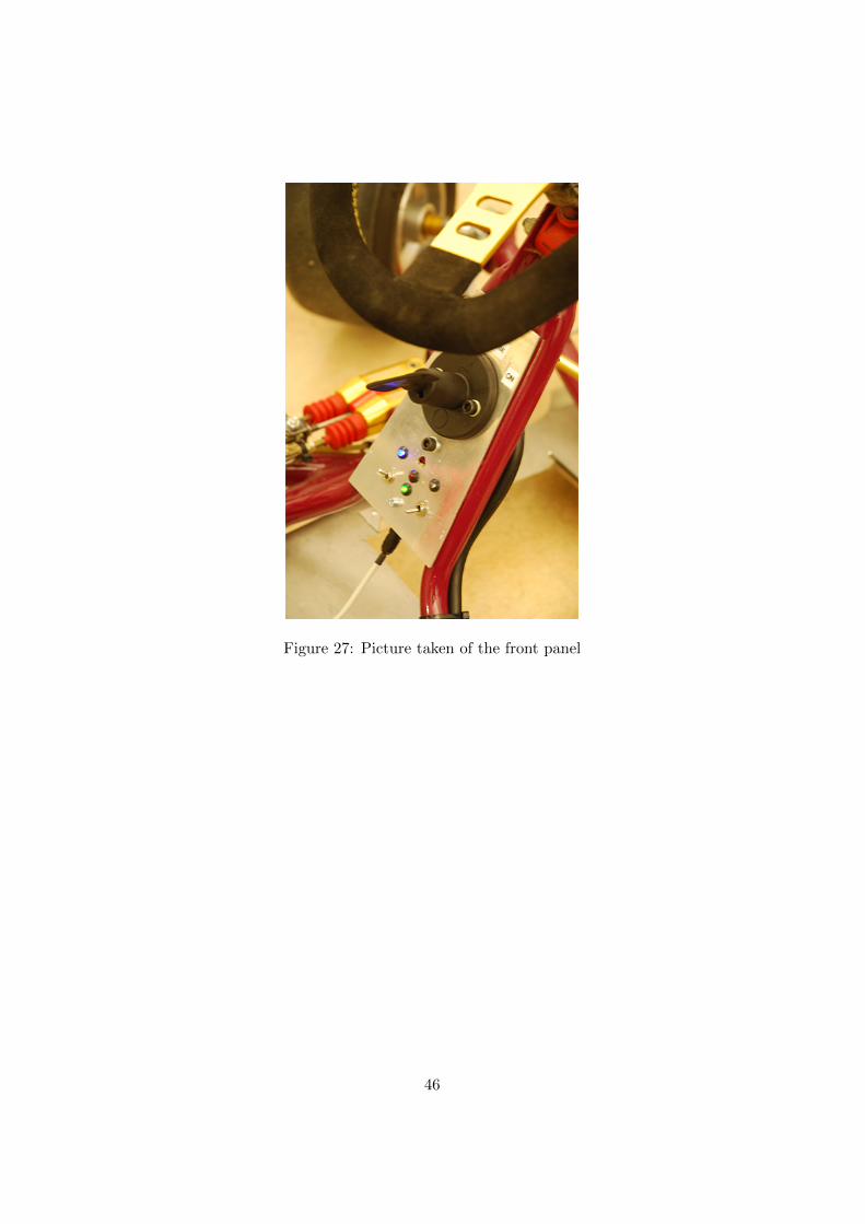
Figure 27: Picture taken of the front panel
46
9 Verification and testing
9.1 Software
Since the DSP (TMS320F2833x) offers real-time analysis, more on this insection 6.1, software verification can be carried out live on the DSP, this hasbeen done both on a evaluation board and on the custom designed controlboard for this project. Details on the software verification will follow in thesections below.
A lot of the software verification was done in multiple steps on differentcircuit boards to be able to verify in parallel with the design of the projectsown circuit board and finally on that board. All tests that were carried outon the old inverter were also done on the new inverter built in the projectand the verification produced positive test results in all cases.
9.1.1 Verification of Current Measurement Calibration
The calibration was done just by starting up the system and checking sothat the offset calibrated would represent 1.5 volt on all systems.
9.1.2 Verification of Current Measurement
Development boardThe current measurement have been verified using a potentiometer inthe range 0.0 to 3.0 volt connected to the current measurement pins.The measured value in the DSP was then compared with a multimeter.
First step with an old inverterIn a first try to verify the current measurement, 3 wires were putthrough a LEM-sensor and was short circuited so that they would run3.0A each. The software reading ranged between 8.5 to 9.0A. The 0.5Awere considered an acceptable margin when discussed with QRTECH.
9.1.3 Verification of Accelerator reference
Development boardThe acceleration reference have been verified using a potentiometer inthe range 0.0 to 3.0 volt connected to the current measurement pins.The measured value in the DSP was then compared with a multimeter.
First step with an old inverterIn a first try to verify the measurement of accelerator reference, two
47
potentiometers in the range 0.0 to 3.0 volt were connected to the con-troller PCB extension port. Then the result in the DSP was comparedwith a multimeter.
9.1.4 Verification of Fan control and temp measurement
Development boardThe fan control have been verified using a potentiometer in the range0.0 to 3.0 volt connected to the temperature measurement pin. Themeasured value in the DSP was then compared with table 5.
First step with an old inverterThe same tests as above were carried out on the development-board.
With a motor and the project’s inverterThe same tests as above were carried out on the old-inverter but thefan was also attached.
9.1.5 Verification of interrupt duty cycle
The time the DSP needs to execute an interrupt is not allowed to exceed theperiod time that interrupt. The interrupt in question is the 40kHz interruptthat controls the SVM generation algorithm. The length in time of theinterrupt was measured by setting a pin high when the interrupt startedand pulling it low when it ended and then the time was measured with anoscilloscope to see if it was under 100% of the period time of the interrupt.The test showed that the marginal is around 30% when running interruptsat 40kHz.
9.1.6 Verification of switching ADC-channels
Since the system is changing which ADC-channels to sample during runtime,it was verified so that the right channels were sampled at the right time andwould not interfere with each other. This was done by using different inputon the different ADC-channels that might interfere with each other andlooking at the sampled data during runtime to see if there were fluctuationsthat shouldn’t be there.
9.1.7 Verification of the Driver Disable
The driver disable was verified with the hardware produced in this project,the testing were done so that the pin was toggled during a run of the system
48
and then the drivers output were looked at through an oscilloscope.
9.1.8 Verification of the Speed Measurement
The verification of the software was done so that during a run with theinverter and a spinning motor, a fixed revolving speed was used to create anangular velocity and then using the primitive function to get the angle asan input to the speed calculations made in the software. The results werealso compared with the data provided by the resolver and the QEP-moduleto see so that they wouldn’t deviate too much from each other.
9.2 Hardware
This section will describe and discuss the testing process of the hardware.Measurements done on the hardware will be discussed and the proceduresfor testing the hardware will also be discussed.
As the hardware was assembled and ready for the first test runs, some firstpower up tests were done. At first the power was just connected to thecontrol PCB and the different voltages on the card were measured. Atthis stage a first problem was encountered, one of the Traco-modules didnot output the correct voltage. An inspection with an IR-camera was thendone to look for malfunctioning components. An OP-amp in the voltagefeedback from the isolated power connected to the Traco-module in questionproved to develop a lot of heat. Since this feedback was from the originaldesign where the isolated power was controlled by the DSP, the OP-ampwas simply removed and the problem thus solved. After the initial powerup test connectivity to the DSP via the JTAG interface was established.
At the first test run in the lab with the motor, a decision was made to dothe test run without the capacitors on the power rings on the power PCB.This was done to enable a comparison between the measurements with andwithout the capacitors. The snubbers on the MOSFETs were not mountedat this stage either. A current limit of about 10A was used on the powersupply to limit the current in case of breakdown. However, this combinationproved catastrophic. As the motor made a few first turns, the lack of inputcapacitance made power supply hit the current limit and then a kind ofoscillation between the inverter and the power supply occurred. This leadto large voltage spikes that eventually lead to a catastrophic failure of the5V regulator and the DSP on the controller PCB.
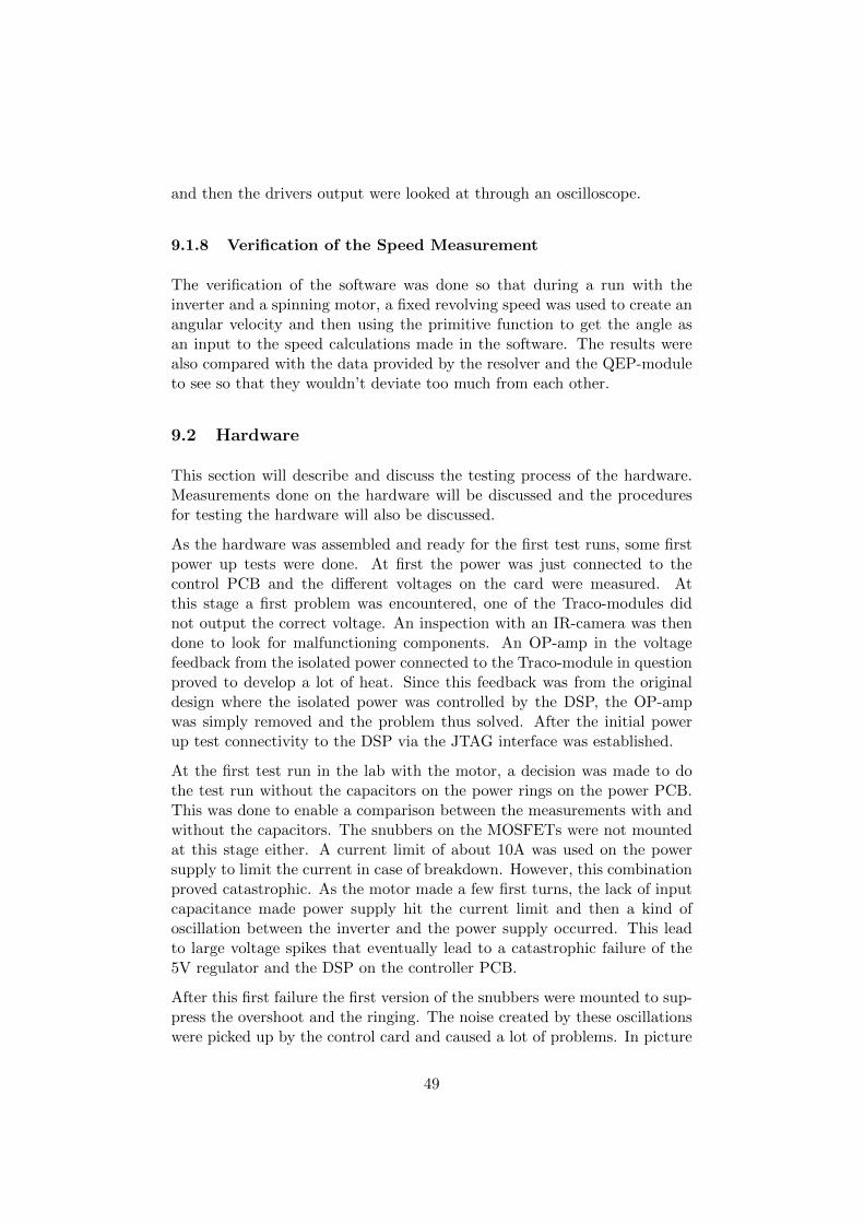
After this first failure the first version of the snubbers were mounted to sup-press the overshoot and the ringing. The noise created by these oscillationswere picked up by the control card and caused a lot of problems. In picture
49
28 the induced oscillations on the 5V supply are clearly visible, at the timeof the measurement, the switching of the half bridges were on but no currentwas output. With larger currents, the ringings became larger in amplitude.
Figure 28: Induced oscillations on 5V supply. Ch1: Source-Drain on upperMOSFET, Ch4: Source-Drain on lower MOSFET and CH3: 5V supply line.
This noise seen on the 5V was also present on the 3.3V supply, since it isderived from the 5V supply, although it were somewhat suppressed.
The resolver with surrounding circuitry showed some severe impact of thisnoise as well, though when measured it didn’t seem as it came from the con-troller PCB, so it was assumed that it was picked up in the cable connectingthe resolver to the PCB. More importantly, it caused a lot of problems onthe feedback signals from the resolver. At every flank of the switching aspike was induced on the signals from the resolver. To suppress this a shieldwas added to the cable and a lot of tuning of the filter on the resolver signalswere done. The noise caused the encoder output of the R/D converter ICto jitter quite badly, and this in turn lead to the angle tracking circuitryin the DSP to count a step backwards every now and then. The filter wasnever really able to suppress the noise to a satisfying level though. Therewere additional problems caused by these ringings where the JTAG deviceused to communicate with the DSP and the DSP itself sustained damage.
As the snubbers and the reverse recovery capacitors were replaced, the os-cillations were suppressed to more acceptable levels, and tests in a rig wherea DC-motor and an electronic load was used to load the motor driven by
50
the inverter. This enabled tests with higher currents. During these tests afinal adjusting of the snubbers was done, to the final values described in sec-tion 7.3.4. From these tests it became apparent that the noise found on thecontrol PCB were strongly coupled to the galvanic contact with the powerPCB through the shared input power from the same power supply. Whenthis was separated almost all of the problems were gone.
These tests in the rig also served to investigate how the input capacitanceon the power PCB is most suitable. Tests were done without the capacitorsmounted on the power PCB, and with external capacitors. Combinationswith a 10mF aluminum capacitor and and 4.7nF plastic film capacitorswere conducted. These capacitors were connected with short cables to theinput terminals on the power PCB. In a test where only the aluminumcapacitor was used, ripple currents were measured to exceed 200A to/fromthe external capacitor. The tests clearly showed that the best choice is tohave the capacitance as close to the half bridges as possible, and thus thesolution with the capacitors mounted on the copper rings deemed to be thebest.
As the input capacitance, snubbers and the reverse recovery capacitors wereadjusted to their final values, almost all of the noise picked up by the con-troller PCB were gone. A presumed problem with the current sensing wasalso discovered during these test, were the DSP reported very large out-put currents (in excess 200A) when the input current were measured in therage of 5 − 30A. This was just assumed to be of lesser importance and nothardware related, so not much attention was given to it at this point.
As the test in the rig were finished, the system was mounted on the actual go-kart and the tests and measurements done in the rig were repeated with thebattery supply. In this case the problem with shared input power from thesame source could not be solved with actual galvanic separation. Thoughthe problem was solved through the use of long separate cables from thebattery to supply the control PCB with input power. As everything seemedto work well, a first test drive was performed. The test drive resulted in another catastrophic failure, where one of the MOSFETs actually exploded. Itwas concluded that an avalanche breakthrough had occurred. After repairs,measurements were taken via a small RC-filter on one of the output phasessimultaneously as the current was measured. This revealed why the outputcurrents was measured as high as they were. The angle tracking offset waswrong and this lead to the inverter driving the motor as a pure inductance,leading to a phase shift between voltage and current of almost 90. Thiswas adjusted in the software and everything worked as intended.
51
10 Result
This section presents the result of the project, a summary of how the goalswere fulfilled and that the set of demands were satisfied.
The primal goal of this project was to redesign an existing inverter to fit achanged set of demands.
Second to this is that the inverter is to be implemented with a completedriveline on an electric go-kart and the go-kart should be drivable.
Supply VoltageThe system can work in a DC supply voltage between 36-72 volt, sincethis is the range of which certain components do work in.
3 phase Alternating CurrentAs can be seen in the choice of transistors, the system should in theorybe able to manage 3x 180A per phase during short intervals which iswell over the 300 that it was specified for. However this has not beentested with currents over 150A flowing out of the inverter.
Torque controlUtilize a closed feedback-loop with a pair of torque-setpoints, current-measurement as feedback together with the rotor-angle of the PMSM.
CoolingAs seen in section 8.1 the system have both an active (fan) and a pas-sive (heat sink) cooling system to prevent the inverter from overheatingand possibly sustaining damage.
MechanicalAs can be seen in section 8 all mechanical parts needed to fit thesystem on the go-kart have been designed and manufactured.
CANHardware support for CAN-communication is implemented to enablefuture development of communication and interactions with the in-verter.
Safety aspectsIn section 3, safety aspects in terms of fault-tolerance and robust-ness have been analyzed and those have also been implemented in theproject.
Angle measurementThe angle feedback from the motor to the control loop should be doneby implementation of a resolver and a R/D (Resolver to Digital) Con-verter IC, prechoosen by QRTECH.
52
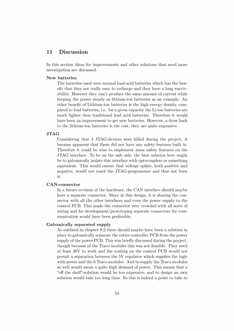
11 Discussion
In this section ideas for improvements and other solutions that need moreinvestigation are discussed.
New batteriesThe batteries used were normal lead-acid batteries which has the ben-efit that they are really easy to recharge and they have a long surviv-ability. However they can’t produce the same amount of current whilekeeping the power steady as lithium-ion batteries as an example. Another benefit of Lithium-ion batteries is the high energy density com-pared to lead batteries, i.e. for a given capacity the Li-ion batteries aremuch lighter then traditional lead acid batteries. Therefore it wouldhave been an improvement to get new batteries. However, a draw backto the lithium-ion batteries is the cost, they are quite expensive.
JTAGConsidering that 4 JTAG-devices were killed during the project, itbecame apparent that these did not have any safety features built in.Therefore it could be wise to implement some safety features on theJTAG interface. To be on the safe side, the best solution here mightbe to galvanically isolate this interface with optocouplers or somethingequivalent. This would ensure that voltage spikes, both positive andnegative, would not reach the JTAG-programmer and thus not burnit.
CAN-connectorIn a future revision of the hardware, the CAN interface should maybehave a separate connector. Since in this design, it is sharing the con-nector with all the other interfaces and even the power supply to thecontrol PCB. This made the connector very crowded with all sorts ofwiring and for development/prototyping separate connectors for com-munication would have been preferable.
Galvanically separated supplyAs outlined in chapter 9.2 there should maybe have been a solution inplace to galvanically separate the entire controller PCB from the powersupply of the power PCB. This was briefly discussed during the project,though because of the Traco modules this was not feasible. They needat least 36V to work and the routing on the control PCB would notpermit a separation between the 5V regulator which supplies the logicwith power and the 6 Traco modules. And to supply the Traco modulesas well would mean a quite high demand of power. This means that a”off the shelf”-solution would be too expensive, and to design an ownsolution would take too long time. So this is indeed a point to take to
53
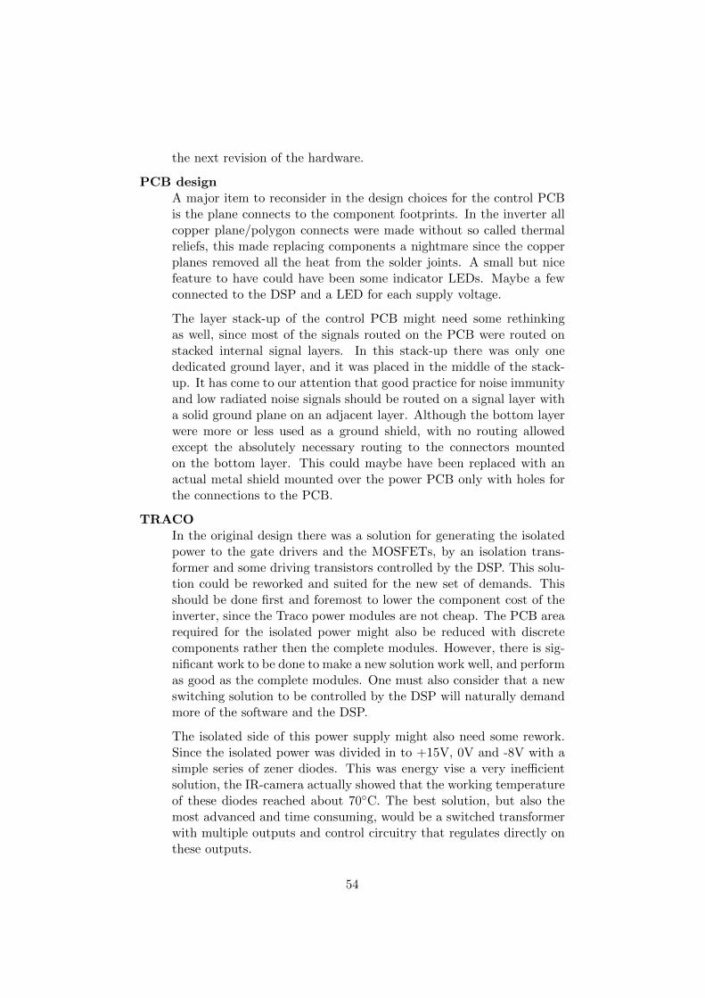
the next revision of the hardware.
PCB designA major item to reconsider in the design choices for the control PCBis the plane connects to the component footprints. In the inverter allcopper plane/polygon connects were made without so called thermalreliefs, this made replacing components a nightmare since the copperplanes removed all the heat from the solder joints. A small but nicefeature to have could have been some indicator LEDs. Maybe a fewconnected to the DSP and a LED for each supply voltage.
The layer stack-up of the control PCB might need some rethinkingas well, since most of the signals routed on the PCB were routed onstacked internal signal layers. In this stack-up there was only onededicated ground layer, and it was placed in the middle of the stack-up. It has come to our attention that good practice for noise immunityand low radiated noise signals should be routed on a signal layer witha solid ground plane on an adjacent layer. Although the bottom layerwere more or less used as a ground shield, with no routing allowedexcept the absolutely necessary routing to the connectors mountedon the bottom layer. This could maybe have been replaced with anactual metal shield mounted over the power PCB only with holes forthe connections to the PCB.
TRACOIn the original design there was a solution for generating the isolatedpower to the gate drivers and the MOSFETs, by an isolation trans-former and some driving transistors controlled by the DSP. This solu-tion could be reworked and suited for the new set of demands. Thisshould be done first and foremost to lower the component cost of theinverter, since the Traco power modules are not cheap. The PCB arearequired for the isolated power might also be reduced with discretecomponents rather then the complete modules. However, there is sig-nificant work to be done to make a new solution work well, and performas good as the complete modules. One must also consider that a newswitching solution to be controlled by the DSP will naturally demandmore of the software and the DSP.
The isolated side of this power supply might also need some rework.Since the isolated power was divided in to +15V, 0V and -8V with asimple series of zener diodes. This was energy vise a very inefficientsolution, the IR-camera actually showed that the working temperatureof these diodes reached about 70C. The best solution, but also themost advanced and time consuming, would be a switched transformerwith multiple outputs and control circuitry that regulates directly onthese outputs.
54
Change battery positionAs of now, all the batteries are placed on one side which makes theweight very unbalanced, this could be fixed by a change in batteryposition.
R/D (Resolver to Digital) Converter ICThe current system have a dedicated IC that is used together withthe resolver both for excitation and interpretation. To reduce cost,alternative solutions to this IC is discussed in the following topics:”Resolver excitation” and ”Angle Tracking Observer (ATO)”
Resolver excitationThe resolver is excited by a 10kHz signal that instead of havingthe IC constructing it, could be constructed by a PWM from theDSP.
Angle Tracking Observer (ATO)An alternative basic method for interpreting the signals from
the resolver in the DSP is to use the inverse tangent method onthe sampled sine and cosine modulated output from the resolver,however this is an approach that gives an unfiltered rotor angleand is therefore sensitive to noise [19].
In the Angle Tracking Observer method, a closed-loop state sys-tem (state observer) replaces the simple inverse tangent functionin order to compute the shaft angle and speed. This is an ap-proach that estimates the rotor angle and having the advantageof rendering a smoother and more accurate rotor angle [19].
An integrator and a PI regulator are connected in series andclosed by a feedback loop. A block-diagram of this can be seenin figure 29.
Figure 29: Block Diagram of the Angle Tracking Observer in the DigitalDomain [20]
55
The error is computed as a sine of the difference of the resolverangle α and the computed angle β as shown in equation 20.
sin(α− β) = sinα× cosβ − cosα× sinβ (20)
For implementation purpose, the sampled resolver outputs arescaled to the range of -1 to 1. After performing this, the AngleTracking Observer can be implemented as equation 21.
ek = RESsin × cos(Θk)−REScos × sin(Θk)
Ωk = Ωk−1 + ek ×K1
Acck = Acck−1 + Ωk−1
Θk+1 = (K2 × Ωk +Acck)× π
K1 =T 2s × ω2
n
π
K2 =2× ζωn × Ts
(21)
Regenerative BrakingThe hardware is prepared to use regenerative braking but was not im-plemented in software because it was outside the scope of the project.It would be a good solution to maximize the utilisation of the battery-power since energy would not be wasted as heat during breaking.
56
12 Conclusion
The primary goal of the project was, as outlined in section 1.2, to redesignan existing inverter to fit a new set of demands on voltage and current.Although the inverter were not fully tested for the upper limits of the voltageand current demands, the redesign was successful. Thus it must also beconcluded that it is not certain that the functionality can be guaranteed atmax specified voltage and current. This is simply because testing equipmentto test under these conditions were not available. The secondary goal, toimplement the inverter in a drive train on a go-kart, was also achieved [21].The finished inverter is a prototype and there is a lot of optimization ofthe hardware design, and as stated before, there is still some testing tobe done. It can also be said that the lead-batteries were probably not intoo good condition, and the go-kart would have more power if they werechanged to lithium based batteries. Concerning the project itself, it can beconcluded that more time could have been spent on project management,but in hindsight, there seemed to be no time for much more. A very clearconclusion is that more then one prototype should have been built, sincemuch of the testing had to wait for the hardware to be repaired after sustaindamage from previous tests.
After the project was finished at QRTECH, we as a group had worked around200 hours over the budget and we still had around 200 hours left to makethe report and presentations done as well. Because of this we feel that sincethis project were fairly large it would have been good to have an extra setof hands with good knowledge in especially electrical design but also goodprogramming knowledge.
57
References
[1] D. Sperling, D. Gordon, and A. Schwarzenegger, Two billion cars: driv-ing toward sustainability. Oxford University Press, USA, 2009.
[2] European Environment Agency. (2011) Size of the vehiclefleet (term 032). [Online]. Available: http://www.eea.europa.eu/data-and-maps/indicators/size-of-the-vehicle-fleet/ds resolveuid/284a9269b0b8e08ac5f5ac29f7886460
[3] United Nations. (2010) World population prospects. [Online]. Available:http://esa.un.org/wpp/unpp/p2k0data.asp
[4] Wikipedia. Can bus. [Online]. Available: http://en.wikipedia.org/wiki/Controller area network
[5] MIT Electric Vehicle Team. (2008) Electric powertrains. [Online].Available: http://web.mit.edu/evt/summary powertrains.pdf
[6] D. O. Neacsu. (2001) Space vector modulation, an in-troduction. [Online]. Available: http://et.upt.ro/admin/tmpfile/fileM1224954797file490353adde0d4.pdf
[7] M. Alakula, Power Electronic Control. KFS, 2003.
[8] IEA, Lund Institute of Technology, Power Electronic Control. KFS,2003.
[9] A. Urquizo. (2011) Pid controller overview. [Online]. Available:http://upload.wikimedia.org/wikipedia/commons/4/43/PID en.svg
[10] B. Thomas, Modern Reglerteknik. Liber, 2008.
[11] Texas Instruments. (2011) Tms320f28335 datasheetl. [Online]. Avail-able: http://www.ti.com/lit/ds/sprs439m/sprs439m.pdf
[12] EPCOS. (2012) Ntc thermistors for temperature measurement.[Online]. Available: http://www.epcos.com/inf/50/db/ntcsmd 11/SMD NTCs NiBarrier Automotive 0603.pdf
[13] Infineon technologies. 1ed020i12f, gate driver ic datasheet. [Online].Available: http://www.infineon.com/dgdl/Datasheet1ED020I12-FV2.1.pdf?folderId=db3a3043132679fb0113346c911c05a4&fileId=db3a30431689f4420116d3baa8120c6c
[14] Infineon technologies. Ipb025n10n3 g, mosfet transistor datasheet. [On-line]. Available: http://www.infineon.com/dgdl/IPB025N10N3+GRe2.03.pdf?folderId=db3a304313b8b5a60113cee8763b02d7&fileId=db3a30431ce5fb52011d1ab1d9d51349&location=en.Products.Discretes Standard Products.MOSFETs.Power MOSFETs.
58
N-Channel MOSFETs 20...250 .DATASHEET.IPB025N10N3%20G Re2.03.pdf
[15] Wikipedia. Thermal resistance. [Online]. Available: http://en.wikipedia.org/wiki/Thermal resistance
[16] H. Seehagel. (2004) Concept of rotor excited resolver. [On-line]. Available: http://upload.wikimedia.org/wikipedia/commons/6/6d/ResolverPrinzip.png
[17] Menner. (2012) Characteristic of a resolver. [Online].Available: http://upload.wikimedia.org/wikipedia/commons/9/91/Resolver-Uebertragungsverhalten.svg
[18] Admotec Inc., “Tech talk 2: Understanding resolvers and r/dconversion,” 1997. [Online]. Available: http://www.admotec.com/TT02.pdf
[19] Freescale Semiconductor., “56f80x resolver driver and hardwareinterface,” 2005. [Online]. Available: http://cache.freescale.com/files/product/doc/AN1942.pdf
[20] Freescale Semiconductor, “Using the resolver interface etpu func-tion,” 2009. [Online]. Available: http://cache.freescale.com/files/microcontrollers/doc/app note/AN3943.pdf
[21] F. Lonnblad, A. Ohlund and QRTECH. (2011, Nov.) Electric gokarttest dirve. [Online]. Available: http://www.youtube.com/watch?v=RFh-Bldvg6M&feature=plcp
59

A Control PCB schematics
I
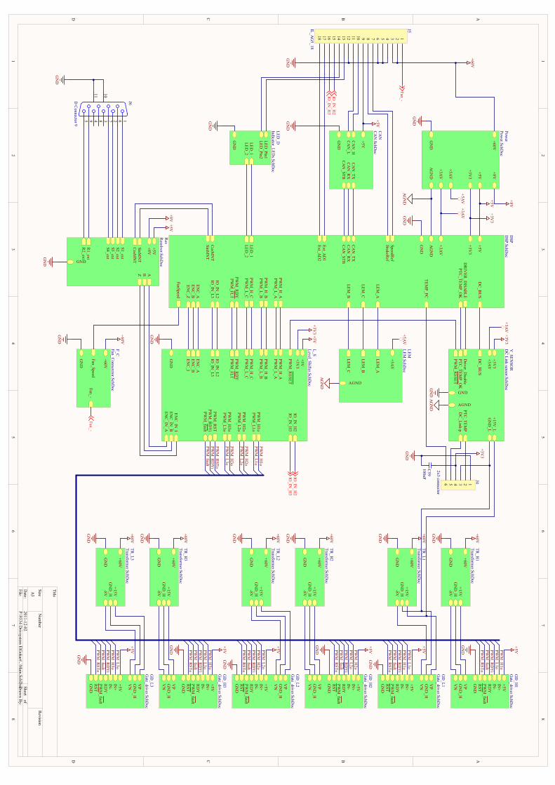
1 1
2 2
3 3
4 4
5 5
6 6
7 7
8 8
DD
CC
BB
AA
Title
Num
berR
evisionSizeA
3
Date:
2011-12-02Sheet of
File:P:\9334 D
rivsystem ElG
okart\..\Main.SchD
ocDraw
n By:
456 3 2 1101112 9 8 7141516 131718
J5IL_AG
5_18
+60V
GN
D
+3V3
+5V
+3AV
+5AV
AG
ND
+8V
Power
Power.SchD
oc
+5V+3V
3
GN
D
PWM
_H1o
PWM
_H_B
PWM
_H_A
PWM
_L_C
PWM
_L_B
PWM
_H_C
PWM
_H2o
PWM
_L_A
PWM
_L1o
PWM
_L3oPW
M_H
3o
PWM
_L2o
ENC
_IN_A
ENC
_IN_B
ENC
_IN_I
ENC
_IEN
C_B
ENC
_A
PWM
_RESET
PWM
_RST
PWM
_FLT
PWM
_fault
PWM
_RD
Y
PWM
_RD
Yi
IO_IN
_L2IO
_IN_L3
IO_IN
_H2
IO_IN
_H3
L_SLevel_Shifter.SchD
oc
CAN
_RX
CAN
_TX
ENC
_BEN
C_A
PTC_TEM
P_OK
DC
_BU
S
TEMP_PC
DR
IVER
_DISA
BLE
+5V
GN
D
+3V3
AG
ND
CAN
_STB
+3AV
PWM
_H_C
PWM
_L_C
PWM
_H_B
PWM
_L_B
PWM
_H_A
PWM
_L_A
LEM_A
LEM_B
LEM_C
ENC
_Z
Ext_AD
1
FanSpeed
PWM
_RD
YPW
M_FLT
Ext_AD
2
SinMN
TC
osMN
T
SpeedRef
BrakeR
ef
LED_1
LED_2
IO_IN
_L2IO
_IN_L3
DSP
DSP.SchD
oc
+5AV
AGND
LEM_A
LEM_B
LEM_C
LEMLEM
.SchDoc
CAN
_HCA
N_L
CAN
_RX
CAN
_TX
CAN
_STB
+5V
GN
D
CAN
CAN
.SchDoc
+15V
GN
DG
ND
_H-8V
+60V
TR_H
1Transform
er.SchDoc
DC
_BU
S
DC
_Link-p
+3AV
AGND
+15V_L
+3V3
GND
PTC_TEM
PD
river_Disable
PTC_TEM
P_OK
PWM
_RESET
GN
D_L
V_SEN
SOR
DC
Link sensor.SchDoc
PWM
_faultR
ST
IN+
VP
VN
+5V
GN
D
IN-
GN
D_H
RD
Y
GD
_H2
Gate_driver.SchD
oc
PWM
_faultR
ST
IN+
VP
VN
+5V
GN
D
IN-
GN
D_H
RD
Y
GD
_L1G
ate_driver.SchDoc
PWM
_faultR
ST
IN+
VP
VN
+5V
GN
D
IN-
GN
D_H
RD
Y
GD
_H1
Gate_driver.SchD
oc+5V
GN
D
+5V
PWM
_faultR
ST
IN+
VP
VN
+5V
GN
D
IN-
GN
D_H
RD
Y
GD
_L2G
ate_driver.SchDoc
PWM
_faultR
ST
IN+
VP
VN
+5V
GN
D
IN-
GN
D_H
RD
Y
GD
_H3
Gate_driver.SchD
oc
PWM
_faultR
ST
IN+
VP
VN
+5V
GN
D
IN-
GN
D_H
RD
Y
GD
_L3G
ate_driver.SchDoc
GN
D
GN
DA
GN
D
GN
DA
GN
D
+5AV
+3AV
+5V+3V
3
GN
D
+60V
PWM
_H1o
PWM
_L1o
PWM
_H2o
PWM
_L2o
PWM
_H3o
PWM
_L3o
PWM
_RSTo
PWM
_RD
Yi
PWM
_fault
PWM
_faultPW
M_R
STo
PWM
_RSTo
PWM
_RSTo
PWM
_RSTo
PWM
_RSTo
PWM
_RSTo
PWM
_fault
PWM
_fault
PWM
_fault
PWM
_fault
PWM
_fault
PWM
_RD
Yi
PWM
_RD
Yi
PWM
_RD
Yi
PWM
_RD
Yi
PWM
_RD
Yi
PWM
_RD
Yi
PWM
_H1o
PWM
_H1o
PWM
_L1o
PWM
_L1o
PWM
_H2o
PWM
_H2o
PWM
_L2o
PWM
_L2o
PWM
_H3o
PWM
_H3o
PWM
_L3o
PWM
_L3o
GN
D
GN
D
GN
D
GN
D
GN
D
+5V
+5V
+5V
+5V
+5V
GN
D
+3V3
+5V+3V
3
AG
ND
+5AV
+3V3
+3AV
GN
D
GN
D
3 12456
J4
2x3 connector
GN
D
+5V
GND
ABZSinM
NT
CosM
NT
S1_extS2_extS3_extS4_ext
R1_ext
R2_ext
+8V
Res
Resolver.SchD
oc
GN
D
Fan_Speed
GN
D
Fan_-
+60V
F_CFan_C
onnerctor.SchDoc
GN
D
+60V
+60V
+15V
GN
DG
ND
_H-8V
+60V
TR_L1
Transformer.SchD
oc
GN
D
+60V
+15V
GN
DG
ND
_H-8V
+60V
TR_H
2Transform
er.SchDoc
GN
D
+60V
+15V
GN
DG
ND
_H-8V
+60V
TR_L2
Transformer.SchD
oc
GN
D
+60V
+15V
GN
DG
ND
_H-8V
+60V
TR_H
3Transform
er.SchDoc
GN
D
+60V
+15V
GN
DG
ND
_H-8V
+60V
TR_L3
Transformer.SchD
oc
GN
D
+60V
IO_IN
_H2
IO_IN
_H3
IO_IN
_H2
IO_IN
_H3
LED_1
LED_2
GN
D
LED_Pin1
LED_Pin2
LED_D
Indicator_LEDs.SchD
oc
GN
D
GN
D
5 4 3 2 19 8 7 6
11 10
J6D C
onnector 9
Fan_-
Fan_-
+5V+8V
+8V
C59
100nFPIC5901 PIC5902COC59
PIJ401
PIJ402
PIJ403PIJ404
PIJ405
PIJ406 COJ4
PIJ501
PIJ502
PIJ503
PIJ504
PIJ505
PIJ506
PIJ507
PIJ508
PIJ509
PIJ5010
PIJ5011
PIJ5012
PIJ5013
PIJ5014
PIJ5015
PIJ5016
PIJ5017
PIJ5018
COJ5
PIJ601
PIJ602
PIJ603
PIJ604
PIJ605
PIJ606
PIJ607
PIJ608
PIJ609
PIJ6010
PIJ6011 COJ6
PIC5902
PIJ404
PIJ509
PIJ502
PIJ503
PIJ501
PIC5901
PIJ401
PIJ504
PIJ505
PIJ506
PIJ5012
PIJ6010
PIJ6011
PIJ5015
PIJ5016
PIJ402
PIJ403
PIJ405
PIJ406
PIJ507
PIJ508
PIJ5010
PIJ5011
PIJ5013
PIJ5014
PIJ5017
PIJ5018
PIJ601
PIJ602
PIJ603
PIJ604
PIJ605
PIJ606
PIJ607
PIJ608
PIJ609
NLPWM0f\a\u\l\t
NLPWM0H1o
NLPWM0H2o
NLPWM0H3o
NLPWM0L1o
NLPWM0L2o
NLPWM0L3o
NLPWM0RDYi
NLPWM0RSTo
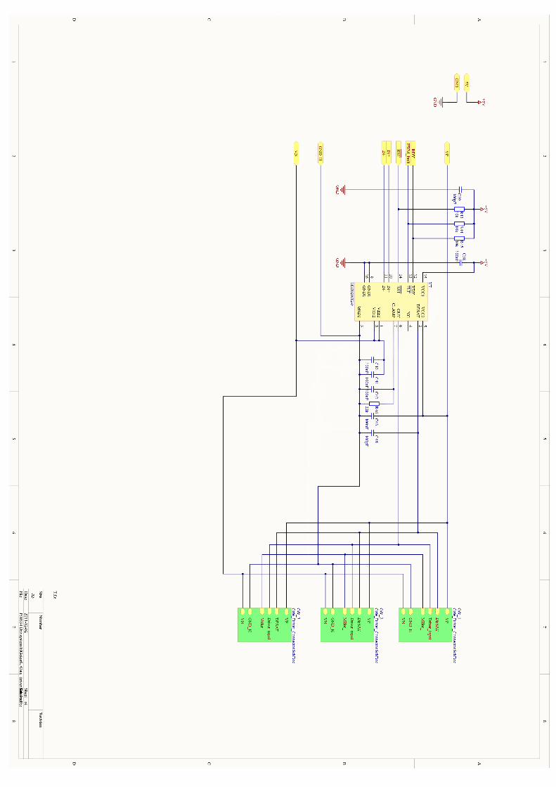
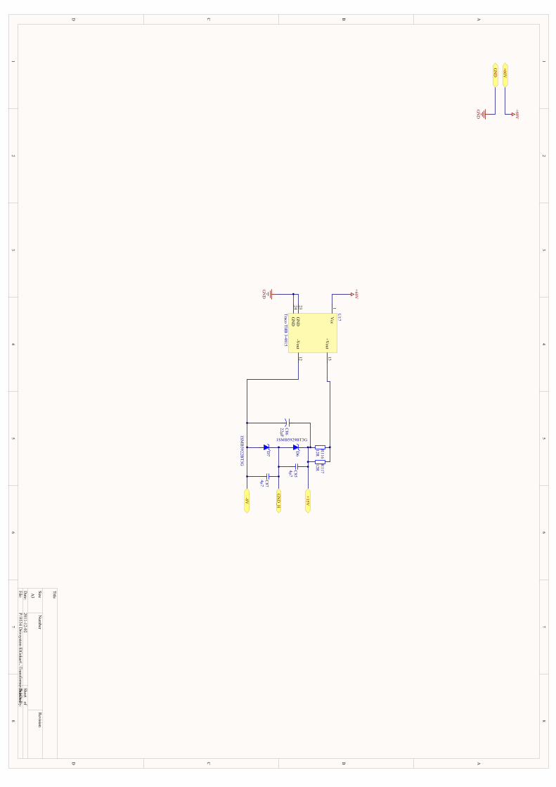
1 1
2 2
3 3
4 4
5 5
6 6
7 7
8 8
DD
CC
BB
AA
Title
Num
berR
evisionSizeA
3
Date:
2011-12-02Sheet of
File:P:\9334 D
rivsystem ElG
okart\..\Transformer.SchD
ocD
rawn B
y:
+15V
+60V
+60V
GN
D
GN
D
C86
22µF
C85
4µ7
C87
4µ7
D6
1SMB5929BT3G
GN
D_H
-8V
R116
12RR
11712R
D7
1SMB
5922BT3G
Vcc
1
+Vout
13
-Vout
12
GN
D24
GN
D23
U17
Traco THB
3-4815
GN
D
+60V
PIC8501 PIC8502COC85
PIC8601 PIC8602COC86
PIC8701 PIC8702COC87
PID601 PID602COD6
PID701 PID702COD7
PIR11601 PIR11602COR116
PIR11701 PIR11702COR117
PIU1701
PIU17012
PIU17013
PIU17023
PIU17024 COU17
PIU1701
PO060V
PIU17023
PIU17024
POGND
PIC8501
PIC8702
PID601PID702POGND0H
PIC8502PIC8602
PID602 PIR11601PIR11701
PO015V
PIC8601
PIC8701PID701
PIU17012
PO08V
PIR11602PIR11702
PIU17013
PO015V
PO060V
PO08V
POGND
POGND0H
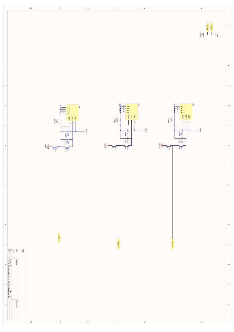
1 1
2 2
3 3
4 4
5 5
6 6
7 7
8 8
DD
CC
BB
AA
Title
Num
berR
evisionSizeA
3
Date:
2011-12-02Sheet of
File:P:\9334 D
rivsystem ElG
okart\..\LEM.SchD
ocDrawn B
y:
C49
100nFC
504n7F
AG
ND
+5AV
+5AV
AG
ND
+5AV
AG
ND
R54
1k8
R55
2k7
AG
ND
LEM_A
C51
100nFC
524n7F
AG
ND
+5AV
R56
1k8
R57
2k7
AG
ND
LEM_B
C53
100nFC
544n7F
AG
ND
+5AV
R58
1k8
R59
2k7
AG
ND
LEM_C
GN
D2
VC
C3
OU
T1
E14 E25 E36 E47
U8
HC
5F300-S
GN
D2
VC
C3
OU
T1
E14 E25 E36 E47
U9
HC
5F300-S
GN
D2
VC
C3
OU
T1
E14 E25 E36 E47
U10
HC
5F300-S
PIC4901 PIC4902COC49
PIC5001 PIC5002COC50
PIC5101 PIC5102COC51
PIC5201 PIC5202COC52
PIC5301 PIC5302COC53PIC5401 PIC5402COC54 PIR5401 PIR5402COR54
PIR5501 PIR5502COR55
PIR5601 PIR5602COR56
PIR5701 PIR5702COR57
PIR5801 PIR5802COR58
PIR5901 PIR5902COR59
PIU801
PIU802
PIU803
PIU804PIU805
PIU806PIU807
COU8
PIU901
PIU902
PIU903
PIU904PIU905
PIU906PIU907
COU9
PIU1001
PIU1002
PIU1003
PIU1004PIU1005
PIU1006PIU1007
COU10
PIC4902PIC5102PIC5302
PIU803
PIU903
PIU1003
PO05AV
PIC4901PIC5001
PIC5101PIC5201
PIC5301PIC5401
PIR5501PIR5701PIR5901
PIU802
PIU804PIU805
PIU806PIU807
PIU902
PIU904PIU905
PIU906PIU907
PIU1002
PIU1004PIU1005
PIU1006PIU1007
POAGND
PIC5002PIR5402
PIU801
PIC5202PIR5602
PIU901
PIC5402PIR5802
PIU1001
PIR5401PIR5502POLEM0A
PIR5601PIR5702POLEM0B
PIR5801PIR5902POLEM0C
PO05AV
POAGND
POLEM0A
POLEM0B
POLEM0C
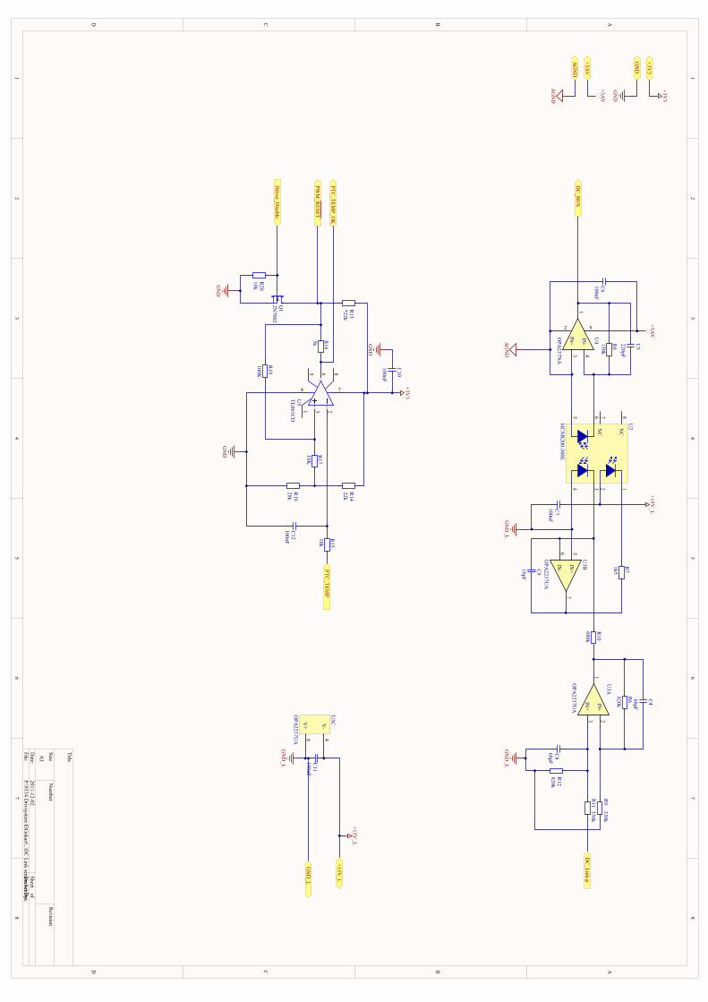
1 1
2 2
3 3
4 4
5 5
6 6
7 7
8 8
DD
CC
BB
AA
Title
Num
berR
evisionSizeA
3
Date:
2011-12-02Sheet of
File:P:\9334 D
rivsystem ElG
okart\..\DC
Link sensor.SchDoc
Draw
n By:
2
IN+
31
5
IN-
4
U4
OPA
237NA
IN+
31
IN-
2U
3A
OPA
2237UA
IN+
57
IN-
6
U3B
OPA
2237UA
R9
330k
R11
330k
R12
820kC
868pF
GN
D_L
R6
820k
C4
68pF
2 14 3
5 6N
C7
NC
8U
2
HC
NR
200-300EC
7100nFG
ND
_L
R7
1k5
+15V_L
C9
10pF
R10
680k
R8
150k
C5
220pF
+3AV
C6
100nF
AG
ND
DC
_BU
S
GN
D_L
DC
_Link-p
V+
8
V-
4U
3C
OPA
2237UA
C11
100nF
GN
D_L
+15V_L
+3AV
+15V_L
AG
ND
+3AV
AG
ND
853 2
674
1U
5TL061C
D
R14
22k
R18
28k
+3V3
GN
D
+3V3
GN
D
+3V3
PTC_TEM
P
Q1
2N7002
R16
5k
R13
*22k
Driver_D
isable
GN
D
R20
10k
PTC_TEM
P_OK
C12
100nF R15
10kPW
M_R
ESET
C10
100nF
GN
D
R17
10K
R19
100K
GN
D
PIC401PIC402 COC4
PIC501PIC502 COC5
PIC601PIC602 COC6
PIC701 PIC702COC7PIC801 PIC802COC8
PIC901PIC902 COC9
PIC1001PIC1002 COC10
PIC1101 PIC1102COC11
PIC1201 PIC1202COC12
PIQ101
PIQ102 PIQ103COQ1
PIR601PIR602
COR6PIR701
PIR702
COR7
PIR801PIR802
COR8
PIR901PIR902
COR9
PIR1001PIR1002
COR10
PIR1101PIR1102
COR11
PIR1201PIR1202
COR12
PIR1301PIR1302
COR13PIR1401PIR1402
COR14
PIR1501PIR1502
COR15
PIR1601PIR1602
COR16
PIR1701PIR1702
COR17
PIR1801PIR1802
COR18
PIR1901PIR1902
COR19PIR2001PIR2002
COR20
PIU201
PIU202
PIU203
PIU204
PIU205
PIU206
PIU207
PIU208 COU2
PIU301
PIU302
PIU303
COU3A
PIU305
PIU306
PIU307
COU3B
PIU304
PIU308
COU3C
PIU401
PIU402PIU403
PIU404
PIU405COU4
PIU501
PIU502
PIU503
PIU504PIU505
PIU506
PIU507PIU508
COU5
PIC601
PIU405PO03AV
PIC1001
PIR1301PIR1401
PIU507
PO03V3
PIC702
PIC1102
PIU202
PIU304
PO015V0L
PIC602
PIU205
PIU402PIU403
POAGND
PIC1002
PIC1201
PIQ102
PIR1802
PIR2002
PIU504
POGND
PIC701PIC801
PIC1101
PIR901
PIR1202
PIU204
PIU305
PIU308
POGND0L
PIC401PIR602
PIR902PIU302
PIC402
PIR601
PIR1002PIU301
PIC501
PIR802
PIU206
PIU404
PIC502
PIR801
PIU401
PODC0BUS
PIC802
PIR1102
PIR1201
PIU303
PIC901 PIR702
PIU307
PIC902
PIR1001PIU203
PIU306
PIC1202
PIR1501PIU502
PIQ101
PIR2001PODriver0Disable
PIQ103 PIR1302
PIR1601
PIR1901
POPWM0R\E\S\E\T\
PIR701PIU201
PIR1101PODC0Link0p
PIR1402
PIR1702
PIR1801
PIR1502POPTC0TEMP
PIR1602PIU506
POPTC0TEMP0OK
PIR1701
PIR1902
PIU503
PIU207
PIU208
PIU501
PIU505
PIU508
PO03AV
PO03V3
PO015V0L
POAGND
PODC0BUS
PODC0LINK0P
PODRIVER0DISABLE
POGND
POGND0L
POPTC0TEMP
POPTC0TEMP0OK
POPWM0R\E\S\E\T\
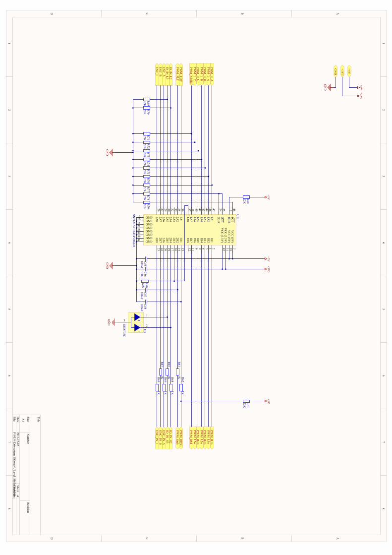
1 1
2 2
3 3
4 4
5 5
6 6
7 7
8 8
DD
CC
BB
AA
Title
Num
berR
evisionSizeA
3
Date:
2011-12-02Sheet of
File:P:\9334 D
rivsystem ElG
okart\..\Level_Shifter.SchDoc
Draw
n By:
R60
22K
GN
D
+5V
R79
22K
GN
D
C55
100nFC
56100nF
+5V+3V
3
R63
1K
R61
22K
C57
100nF
+5V
+5V
+3V3
GN
D
+5V+3V
3
GN
D
PWM
_H1o
PWM
_RD
Y
PWM
_H_B
PWM
_H_A
PWM
_L_C
PWM
_fault
PWM
_L_BPW
M_H
_C
PWM
_H2o
PWM
_L_APW
M_L1o
PWM
_L3oPW
M_H
3oPW
M_L2o
R68
1K
R78
22KR
7722K
R76
22KR
7522K
R74
22KR
7322K
R72
22KR
7122K
R67
1K R66
1KEN
C_IN
_AEN
C_IN
_BEN
C_IN
_IEN
C_I
ENC
_BEN
C_A
PWM
_RESET
PWM
_RST
PWM
_RD
Yi
R62
1K
C58
100nF
PWM
_FLT
GN
D
2DIR
24
1A2
46
1A7
38
2OE
25
1A3
44
1A1
47
1A6
40
1DIR
1
1A5
411A
443
1OE
48
2A2
35
2A7
27
1A8
37
2A6
29
2A8
26
2A1
36
2A3
33
2A5
302A
432
GND4
GND10
GND15
GND21
GND28
GND34
GND39
GND45
VC
C (5V
)7
VC
C (5V
)18
VC
C (3.3V
)31
VC
C (3.3V
)42
1B7
11
1B2
3
1B6
9
1B8
12
1B3
5
1B4
6
1B5
8
1B1
2
2B7
22
2B2
14
2B3
16
2B1
13
2B8
23
2A6
20
2B4
17
2B5
19
U11
SN74A
LVC
164245DG
GR
R80
22K
IO_IN
_L2IO
_IN_L3
R70
22KR
6922K
R64
1KR
651K
IO_IN
_H2
IO_IN
_H3
1
3
2
D3
GSO
T05C
PIC5501 PIC5502COC55PIC5601 PIC5602COC56PIC5701 PIC5702COC57
PIC5801 PIC5802COC58PID301
PID302
PID303
COD3
PIR6001 PIR6002COR60
PIR6101 PIR6102COR61
PIR6201PIR6202
COR62
PIR6301PIR6302
COR63
PIR6401PIR6402
COR64
PIR6501PIR6502
COR65
PIR6601PIR6602
COR66
PIR6701PIR6702
COR67
PIR6801PIR6802
COR68
PIR6901 PIR6902COR69PIR7001 PIR7002COR70
PIR7101 PIR7102COR71PIR7201 PIR7202COR72PIR7301 PIR7302COR73PIR7401 PIR7402COR74PIR7501 PIR7502COR75PIR7601 PIR7602COR76PIR7701 PIR7702COR77PIR7801 PIR7802COR78PIR7901 PIR7902COR79
PIR8001 PIR8002COR80
PIU1101
PIU1102
PIU1103
PIU1104
PIU1105
PIU1106
PIU1107
PIU1108
PIU1109
PIU11010
PIU11011
PIU11012
PIU11013
PIU11014
PIU11015
PIU11016
PIU11017
PIU11018
PIU11019
PIU11020
PIU11021
PIU11022
PIU11023
PIU11024
PIU11025
PIU11026
PIU11027
PIU11028
PIU11029
PIU11030
PIU11031
PIU11032
PIU11033
PIU11034
PIU11035
PIU11036
PIU11037
PIU11038
PIU11039
PIU11040
PIU11041
PIU11042
PIU11043
PIU11044
PIU11045
PIU11046
PIU11047
PIU11048 COU11
PIC5602
PIU11031
PIU11042
PO03V3
PIC5502
PIR6002PIR6102
PIU1107
PIU11018
PO05V
PIC5501PIC5601
PIC5701PIC5801
PID303
PIR6901PIR7001
PIR7101PIR7201
PIR7301PIR7401
PIR7501PIR7601
PIR7701PIR7801
PIR7901PIR8001
PIU1104PIU11010PIU11015PIU11021PIU11028PIU11034PIU11039PIU11045
POGND
PIC5702
PIR6302PIU11014
PIC5802
PIR6202PIU11013
PID301
PIR6502PIU11019
PID302
PIR6402PIU11017
PIR6001
PIU1101
PIR6101
PIR6201POPWM0RDYi
PIR6301POPWM0f\a\u\l\t
PIR6401POIO0IN0H2
PIR6501POIO0IN0H3
PIR6601POENC0IN0A
PIR6602PIU11020
PIR6701POENC0IN0B
PIR6702PIU11022
PIR6801POENC0IN0I
PIR6802PIU11023
PIR6902
PIU11030POIO0IN0L3
PIR7002
PIU11032POIO0IN0L2
PIR7102
PIU11038POPWM0R\E\S\E\T\
PIR7202
PIU11040POPWM0L0C
PIR7302
PIU11041POPWM0H0C
PIR7402
PIU11043POPWM0L0B
PIR7502
PIU11044POPWM0H0B
PIR7602
PIU11046POPWM0L0A
PIR7702
PIU11047POPWM0H0A
PIR7802
PIU11024
PIU11025
PIR7902
PIU11048
PIR8002
PIU11016
PIU11037
PIU1102
POPWM0H1o
PIU1103
POPWM0L1o
PIU1105
POPWM0H2o
PIU1106
POPWM0L2o
PIU1108
POPWM0H3o
PIU1109
POPWM0L3o
PIU11011POPWM0RST
PIU11012
PIU11026POENC0I
PIU11027POENC0B
PIU11029POENC0A
PIU11033
PIU11035POPWM0F\L\T\
PIU11036POPWM0RDY
PO03V3
PO05V
POENC0A
POENC0B
POENC0I
POENC0IN0A
POENC0IN0B
POENC0IN0I
POGND
POIO0IN0H2
POIO0IN0H3
POIO0IN0L2
POIO0IN0L3
POPWM0F\A\U\L\TPOPWM0F\L\T\
POPWM0H1O
POPWM0H2O
POPWM0H3O
POPWM0H0A
POPWM0H0B
POPWM0H0C
POPWM0L1O
POPWM0L2O
POPWM0L3O
POPWM0L0A
POPWM0L0B
POPWM0L0C
POPWM0R\E\S\E\T\
POPWM0RDY
POPWM0RDYI
POPWM0RST
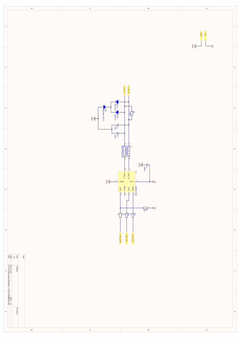
1 1
2 2
3 3
4 4
5 5
6 6
7 7
8 8
DD
CC
BB
AA
Title
Num
berR
evisionSizeA
3
Date:
2011-12-02Sheet of
File:P:\9334 D
rivsystem ElG
okart\..\CAN
.SchDocD
rawn B
y:
14
23
L1B82789S223N
2SPLIT
5
TXD
1
RX
D4
CAN
_H7
STB8
CAN
_L6
VCC 3GND2
U1
AM
IS-42665
D1A
BAV
23D
1BBA
V23
CAN
_H
CAN
_L
C2
47pFC
347pF
GN
D
D2
BZX
84C33LT1
R2
1kR4
1kR5
1k
R1
22k
+5V+5V
C1
100nF
GN
D
GN
D
CAN
_RX
CAN
_TX
CAN
_STB
+5V
GN
D
+5V
GN
D
R3
120R
PIC101PIC102 COC1
PIC201 PIC202COC2PIC301 PIC302
COC3
PID101 PID104COD1A
PID102 PID103COD1B
PID201 PID203COD2
PIL101
PIL102
PIL103
PIL104 COL1
PIR101 PIR102COR1PIR201PIR202
COR2
PIR301PIR302
COR3
PIR401PIR402
COR4
PIR501PIR502
COR5
PIU101
PIU102 PIU103PIU104
PIU105
PIU106
PIU107
PIU108
COU1
PIC101PIR102
PIU103
PO05V
PIC102
PIC201PIC301
PID201
PIU102
POGND
PIC202PID104
PIL101
PIR302
POCAN0H
PIC302PID103
PIL104
PIR301
POCAN0L
PID101PID102
PID203
PIL102
PIU107
PIL103
PIU106
PIR101
PIR501PIU108
PIR201PIU104
PIR202POCAN0RX
PIR401
PIU101
PIR402POCAN0TX
PIR502POCAN0STB
PIU105
PO05V
POCAN0H
POCAN0L
POCAN0RX
POCAN0STB
POCAN0TX
POGND
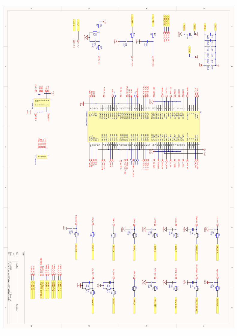
1 1
2 2
3 3
4 4
5 5
6 6
7 7
8 8
DD
CC
BB
AA
Title
Num
berR
evisionSizeA
3
Date:
2011-12-02Sheet of
File:P:\9334 D
rivsystem ElG
okart\..\DSP.SchD
ocDraw
n By:
TDI
97
TDO
98
TRSTn
99
EMU
0100
5V96
GPIO
-3395
GPIO
-3194
GPIO
-2993
5V92
GPIO
-2391
5V87
GPIO
-1788
GPIO
-1989
GPIO
-2190
GPIO
-2786
GPIO
-2585
GPIO
-1484
GPIO
-1383
5V82
GPIO
-8581
5V77
GPIO
-0978
GPIO
-1179
GPIO
-4980
GPIO
-0776
GPIO
-0575
GPIO
-0374
GPIO
-0173
GPIO
-6372
AD
C-A
771
AD
C-A
567
GPIO
-5968
AD
C-A
669
GPIO
-6170
VR
EF-HI
66A
DC
-A4
65G
ND
64A
DC
-A3
63G
ND
62A
DC
-A2
61
AD
C-A
057
GN
D58
AD
C-A
159
GN
D60
GN
D-ISO
56N
C55
NC
54N
C53
TX-ISO
523v3-ISO
51
GN
D47
TCK
48
TMS
49
EMU
150
GPIO
-3446
GPIO
-3245
GPIO
-3044
GPIO
-2843
GPIO
-8742
GPIO
-2241
GN
D37
GPIO
-1638
GPIO
-1839
GPIO
-2040
GPIO
-2636
GPIO
-2435
GPIO
-1534
GPIO
-1233
GPIO
-8632
GPIO
-8431
GN
D27
GPIO
-0828
GPIO
-1029
GPIO
-4830
GPIO
-0626
GPIO
-0425
GPIO
-0224
GPIO
-0023
GPIO
-6222
AD
C-B
721
AD
C-B
517
GPIO
-5818
AD
C-B
619
GPIO
-6020
VR
EF-LO16
AD
C-B
415
GN
D14
AD
C-B
313
GN
D12
AD
C-B
211
AD
C-B
07
GN
D8
AD
C-B
19
GN
D10
GN
D-ISO
6N
C5
NC
4N
C3
RX
-ISO2
3V3-ISO
1U
6
F28335 control card
3 124
J22x2 connector
5 1376 248
13 91114 1012
J12x7 connector
3V3_ISO
TX_ISO
RX
_ISOG
ND
_ISO
3V3_ISO
RX
_ISO
GN
D_ISO
3V3_ISO
TX_ISO
GN
D_ISO
TMS
TDI
TDO
TCK
EMU
0
TRSTn
EMU
1
TMS
TCK
TDI
TDO
TRSTn
EMU
0EM
U1
GN
D
+3V3
CAN
_TXCA
N_R
X
CAN
_TXCA
N_R
X
PWM
_H_C
PWM
_L_CPW
M_H
_CPW
M_L_C
PWM
_H_B
PWM
_L_BPW
M_H
_BPW
M_L_B
PWM
_H_A
PWM
_L_APW
M_H
_APW
M_L_A
Sin_MN
T
Speed_ref
LEM-B
LEM_A
LEM-A
LEM-A
ENC
-BEN
C-Z
ENC
-A
PWM
_H_C
PWM
_H_B
PWM
_H_A
PWM
_L_CPW
M_L_B
PWM
_L_A
PTC_TEM
P_OK
PTC-TEM
P_OK
PTC-TEM
P_OK
DC
_BU
SD
C-B
US
DC
-BU
S
TEMP_PC
TEMP-PC
TEMP-PC
DR
IVER
_DISA
BLE
DR
IVER
_DISA
BLE
DR
IVER
_DISA
BLE
GN
D
AG
ND
AG
ND
+5V+3A
V
C16
100nF
C17
100nF
C18
100nF
C19
100nF
C20
100nF
C15
2µ2F
C23
100nF
+5V
+3AV
GN
D
AG
ND
TP2TP1TP3
TP5
TP4
EXT-A
D2
R21
10kC
13100nF
AG
ND
R23
1kC
2110nF
AG
ND
R24
10kC
22100nF
GN
D
R25
50RC
24*10nF
AG
ND
R26
10KC
25100nF
AG
ND
LEM_B
LEM-B
R27
50RC
26*10nF
AG
ND
R28
10KC
27100nF
AG
ND
LEM_C
LEM-C
R30
50RC
29*10nF
AG
ND
R37
10KC
34100nF
AG
ND
ENC
_AEN
C-A
R33
100R
ENC
_BEN
C-B
R31
100R
ENC
_ZEN
C-Z
R39
100R
CAN
_STB
CAN
_STB
R40
1K8
C36
10nF
GN
D
CAN
_TX
+5V
GN
D
+3AV
AG
ND
CAN
_RX
CAN
_STB
IO_IN
_L3
IO_IN
_L3
EXT-A
D2
Ext_AD
1R
29
1k
C28
10nF
GN
D
+3V3
+3V3
LEM-B
LEM-A
LEM-C
LEM-C
Cos_M
NT
Brake_ref
FanSpeed
FanSpeedFanSpeed
PWM
_OK
PWM
_FLT
PWM
_OK
PWM
_RD
Y
PWM
_FLTPW
M_FLT
5V_ref
5V_ref
EXT-A
D1
EXT-A
D1
Ext_AD
2R
32
1k
C31
10nF
GN
D
+5AVR
36
2k7R
382k7
R34
1K8
C33
10nF
GN
D
Sin_MN
T
Cos_M
NT
SinMN
T
CosM
NT
IO_IN
_L2IO
_IN_L3
IO_IN
_L2
IO_IN
_L2
Speed_refSpeedR
efR
22
10kC
14100nF
GN
D
Brake_ref
BrakeR
efR
42
10kC
37100nF
GN
D
LED_1
LED_2
LED_1
LED_2
LED_1
LED_2
R35
2K2
R41
2K2
PIC1301 PIC1302COC13PIC1401 PIC1402COC14
PIC1501 PIC1502 COC15PIC1601 PIC1602 COC16
PIC1701 PIC1702 COC17PIC1801 PIC1802 COC18
PIC1901 PIC1902 COC19PIC2001 PIC2002 COC20
PIC2101 PIC2102COC21PIC2201 PIC2202COC22
PIC2301 PIC2302 COC23
PIC2401 PIC2402COC24PIC2501 PIC2502COC25
PIC2601 PIC2602COC26PIC2701 PIC2702COC27
PIC2801 PIC2802COC28
PIC2901 PIC2902COC29
PIC3101 PIC3102COC31
PIC3301 PIC3302COC33
PIC3401 PIC3402COC34
PIC3601 PIC3602COC36
PIC3701 PIC3702COC37
PIJ101
PIJ102
PIJ103
PIJ104
PIJ105
PIJ106
PIJ107
PIJ108
PIJ109
PIJ1010
PIJ1011
PIJ1012
PIJ1013PIJ1014
COJ1
PIJ201
PIJ202
PIJ203
PIJ204 COJ2
PIR2101PIR2102
COR21PIR2201
PIR2202
COR22
PIR2301PIR2302
COR23PIR2401
PIR2402COR24
PIR2501PIR2502
COR25PIR2601
PIR2602
COR26
PIR2701PIR2702
COR27PIR2801
PIR2802
COR28
PIR2901PIR2902
COR29
PIR3001PIR3002
COR30PIR3101
PIR3102COR31
PIR3201PIR3202
COR32
PIR3301PIR3302
COR33PIR3401
PIR3402
COR34
PIR3501 PIR3502COR35
PIR3601PIR3602 COR36
PIR3701PIR3702
COR37
PIR3801PIR3802 COR38
PIR3901PIR3902
COR39PIR4001
PIR4002COR40
PIR4101 PIR4102COR41
PIR4201PIR4202
COR42
PITP101COTP1
PITP201COTP2
PITP301COTP3
PITP401COTP4
PITP501COTP5
PIU601
PIU602
PIU603
PIU604
PIU605
PIU606
PIU607
PIU608
PIU609
PIU6010
PIU6011
PIU6012
PIU6013
PIU6014
PIU6015
PIU6016
PIU6017
PIU6018
PIU6019
PIU6020
PIU6021
PIU6022
PIU6023
PIU6024
PIU6025
PIU6026
PIU6027
PIU6028
PIU6029
PIU6030
PIU6031
PIU6032
PIU6033
PIU6034
PIU6035
PIU6036
PIU6037
PIU6038
PIU6039
PIU6040
PIU6041
PIU6042
PIU6043
PIU6044
PIU6045
PIU6046
PIU6047
PIU6048
PIU6049
PIU6050
PIU6051
PIU6052
PIU6053
PIU6054
PIU6055
PIU6056
PIU6057
PIU6058
PIU6059
PIU6060
PIU6061
PIU6062
PIU6063
PIU6064
PIU6065
PIU6066
PIU6067
PIU6068
PIU6069
PIU6070
PIU6071
PIU6072
PIU6073
PIU6074
PIU6075
PIU6076
PIU6077
PIU6078
PIU6079
PIU6080
PIU6081
PIU6082
PIU6083
PIU6084
PIU6085
PIU6086
PIU6087
PIU6088
PIU6089
PIU6090
PIU6091
PIU6092
PIU6093
PIU6094
PIU6095
PIU6096
PIU6097
PIU6098
PIU6099
PIU60100
COU6
PIC2302
PIU6066
PO03AV
PIJ105
PO03V3
PIR3602
PIC1502PIC1602
PIC1702PIC1802
PIC1902PIC2002
PIU6077
PIU6082
PIU6087
PIU6092
PIU6096
PO05V
PIJ201
PIU601
PIU6051
PIR3702
PIU6063
PIC1301PIC2101PIC2301
PIC2401PIC2501
PIC2601PIC2701
PIC2901
PIC3401PIR3802
PIU608
PIU6010
PIU6012
PIU6014
PIU6016
PIU6058
PIU6060
PIU6062
PIU6064
POAGND
PIC3702PIR4201
PIU6017
PIU6044
POCAN0RX
PIU6095
POCAN0STB
PIU6094
POCAN0TX
PIC3602PIR4001
PIR4102
PIU6015
PIC1302PIR2101
PIU6071
PIU6080
PODRIVER0DISABLE
PIJ1013
PIU60100
PIJ1014
PIU6050
PIR3301PIU6040
PIR3101
PIU6090
PIR3901
PIU6091
PIC3102
PIR3202
PIU6013
PIC2802
PIR2902PIU6021
PIU6028
POFanSpeed
PIC1401PIC1501
PIC1601PIC1701
PIC1801PIC1901
PIC2001
PIC2201
PIC2801PIC3101
PIC3301PIC3601
PIC3701
PIJ104
PIJ108
PIJ1010
PIJ1012
PIR3501PIR4101
PIU6027
PIU6037
PIU6047
POGND
PIJ204
PIU606
PIU6056
PIU6036
POIO0IN0L2
PIU6086
POIO0IN0L3
PIU6031
POLED01
PIU6032
POLED02
PIC2402PIR2501
PIU6057
PIU6059
PIC2602PIR2701
PIU607
PIU6061
PIC2902PIR3001
PIU609
PIU6011
PIC3402PIR3601
PIR3701PIR3801
PIJ106
PIR2102PODC0BUS
PIR2202POSpeedRef
PIR2302POTEMP0PC
PIR2402POPTC0TEMP0OK
PIR2502POLEM0A
PIR2602POPWM0RDY
PIR2702POLEM0B
PIR2802POPWM0F\L\T\
PIR2901POExt0AD1
PIR3002POLEM0C
PIR3102POENC0B
PIR3201POExt0AD2
PIR3302POENC0A
PIR3402POSinMNT
PIR3902POENC0Z
PIR4002POCosMNT
PIR4202POBrakeRef
PITP101PIU6078
PITP201PIU6029
PITP301PIU6079
PITP401PIU6081
PITP501PIU6039
PIU603
PIU604
PIU605
PIU6018
PIU6019
PIU6020
PIU6022
PIU6026
PIU6030
PIU6034
PIU6035
PIU6038
PIU6041
PIU6042
PIU6043
PIU6045
PIU6046
PIU6053
PIU6054
PIU6055
PIU6068
PIU6070
PIU6072
PIU6076
PIU6085
PIU6088
PIU6089
PIU6093
PIC2202PIR2401
PIU6084
PIC2702PIR2801
PIU6033
PIU6023
POPWM0H0A
PIU6024
POPWM0H0B
PIU6025
POPWM0H0C
PIU6073
POPWM0L0A
PIU6074
POPWM0L0B
PIU6075
POPWM0L0C
PIC2502PIR2601
PIU6083
PIJ203
PIU602
PIC3302PIR3401
PIR3502
PIU6065
PIC1402PIR2201
PIU6067
PIJ109
PIJ1011
PIU6048
PIJ103
PIU6097
PIJ107
PIU6098
PIC2102PIR2301
PIU6069
PIJ101
PIU6049
PIJ102
PIU6099
PIJ202
PIU6052
PO03AV
PO03V3
PO05V
POAGND
POBRAKEREF
POCAN0RX
POCAN0STB
POCAN0TX
POCOSMNT
PODC0BUS
PODRIVER0DISABLE
POENC0A
POENC0B
POENC0Z
POEXT0AD1
POEXT0AD2
POFANSPEED
POGND
POIO0IN0L2
POIO0IN0L3
POLED01
POLED02
POLEM0A
POLEM0B
POLEM0C
POPTC0TEMP0OK
POPWM0F\L\T\
POPWM0H0A
POPWM0H0B
POPWM0H0C
POPWM0L0A
POPWM0L0B
POPWM0L0C POPWM0RDY
POSINMNT
POSPEEDREF
POTEMP0PC
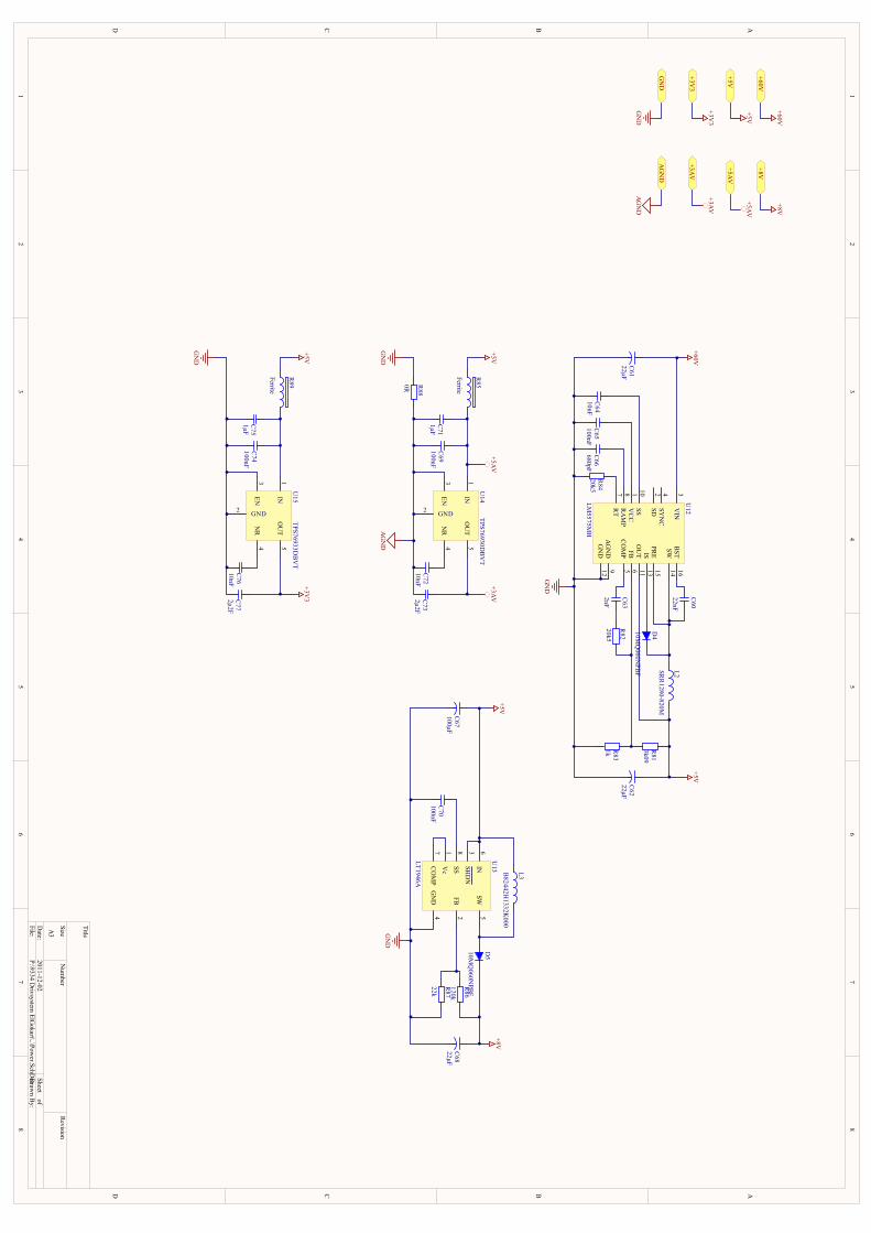
1 1
2 2
3 3
4 4
5 5
6 6
7 7
8 8
DD
CC
BB
AA
Title
Num
berR
evisionSizeA
3
Date:
2011-12-02Sheet of
File:P:\9334 D
rivsystem ElG
okart\..\Power.SchD
ocDrawn B
y:
+60V
+60V
GN
D
GN
D
+3V3
+3V3
R84
20k5C
66680pF
C64
10nFC
65100nF
C61
22µF
+60VC
60
22nF
C63
2nF
R82
20k5
R81
3k09
R83
1k
C62
22µF
D4
10MQ
060NPBF L2SR
R1280-820M
+5V
+5V
+5V
EN3
GND2
IN1
OU
T5
NR
4
U14
TPS76930DB
VT
EN3
GND2
IN1
OU
T5
NR
4
U15
TPS76933DB
VT
C71
1µFC
69100nF
C73
2µ2FC
7210nF
R85
Ferrite
R89
Ferrite
GN
D
+5V
+5V
C75
1µFC
74100nF
C77
2µ2FC
7610nF
GN
D
AG
ND
+5AV
+3AV
+3V3
+3AV
+3AV
+5AV
+5AV
AG
ND
AG
ND
SD2
SS10
SYN
C4
RAM
P8
VC
C1
VIN
3
RT
7
FB6
CO
MP
5
SW14
PRE
15
BST
16
AG
ND
9
GN
D12
IS13
OU
T11
U12
LM5575M
H
GN
D
R88
0R
SHD
N3
Vc
1
IN6
SW5
SS8
CO
MP
7
FB2
GN
D4
U13
LT1946A
C67
100µF
+5V
C70
100nF
L3B82442H
1332K000
D5
10MQ
060NPBFR
86
120kR
87
22k
GN
D
C68
22µF
+8V
+8V
+8V
PIC6001PIC6002
COC60
PIC6101 PIC6102COC61
PIC6201 PIC6202COC62
PIC6301PIC6302
COC63
PIC6401PIC6402 COC64PIC6501PIC6502 COC65
PIC6601PIC6602 COC66
PIC6701 PIC6702COC67
PIC6801 PIC6802COC68
PIC6901PIC6902 COC69PIC7001PIC7002 COC70
PIC7101 PIC7102COC71PIC7201PIC7202 COC72
PIC7301 PIC7302COC73
PIC7401PIC7402 COC74PIC7501 PIC7502COC75
PIC7601PIC7602 COC76PIC7701 PIC7702COC77
PID401PID402
COD4
PID501PID502
COD5
PIL201PIL202
COL2
PIL301PIL302
COL3
PIR8101 PIR8102COR81
PIR8201PIR8202 COR82
PIR8301 PIR8302COR83
PIR8401 PIR8402COR84
PIR8501PIR8502
COR85
PIR8601PIR8602
COR86
PIR8701PIR8702
COR87
PIR8801PIR8802 COR88
PIR8901PIR8902
COR89
PIU1201
PIU1202
PIU1203
PIU1204
PIU1205
PIU1206
PIU1207
PIU1208
PIU1209
PIU12010
PIU12011
PIU12012
PIU12013
PIU12014
PIU12015
PIU12016
COU12
PIU1301
PIU1302
PIU1303
PIU1304
PIU1305
PIU1306
PIU1307
PIU1308 COU13
PIU1401
PIU1402PIU1403
PIU1404
PIU1405
COU14
PIU1501
PIU1502PIU1503
PIU1504
PIU1505
COU15
PIC7302
PIU1405
PO03AV
PIC7702
PIU1505
PO03V3
PIC6901PIC7102
PIR8502PIU1401
PO05AV
PIC6202
PIC6702
PIL202
PIL301
PIR8102
PIR8501
PIR8901
PIU12011
PIU1303
PIU1306
PO05V
PIC6802
PID502
PIR8602
PO08V
PIC6102
PIU1203
PO060V
PIC6902PIC7101
PIC7202PIC7301
PIR8801
PIU1402PIU1403
POAGND
PIC6101PIC6201
PIC6402PIC6502
PIC6602
PIC6701PIC6801
PIC7002
PIC7402PIC7501
PIC7602PIC7701
PIR8301
PIR8401
PIR8702
PIR8802
PIU1209
PIU12012
PIU12017
PIU1304
PIU1309
PIU1502PIU1503
POGND
PIC6001
PIU12016
PIC6002
PID402
PIL201PIU12014
PIU12015
PIC6301
PIU1205
PIC6302PIR8202
PIC6401
PIU12010
PIC6501
PIU1201
PIC6601
PIU1208
PIC7001PIU1308
PIC7201PIU1404
PIC7401PIC7502
PIR8902PIU1501
PIC7601PIU1504
PID401PIU12013
PID501
PIL302PIU1305
PIR8101
PIR8201
PIR8302PIU1206
PIR8402PIU1207
PIR8601
PIR8701
PIU1302
PIU1202
PIU1204
PIU1301
PIU1307
PO03AV
PO03V3
PO05AV
PO05V
PO08V
PO060V
POAGND
POGND
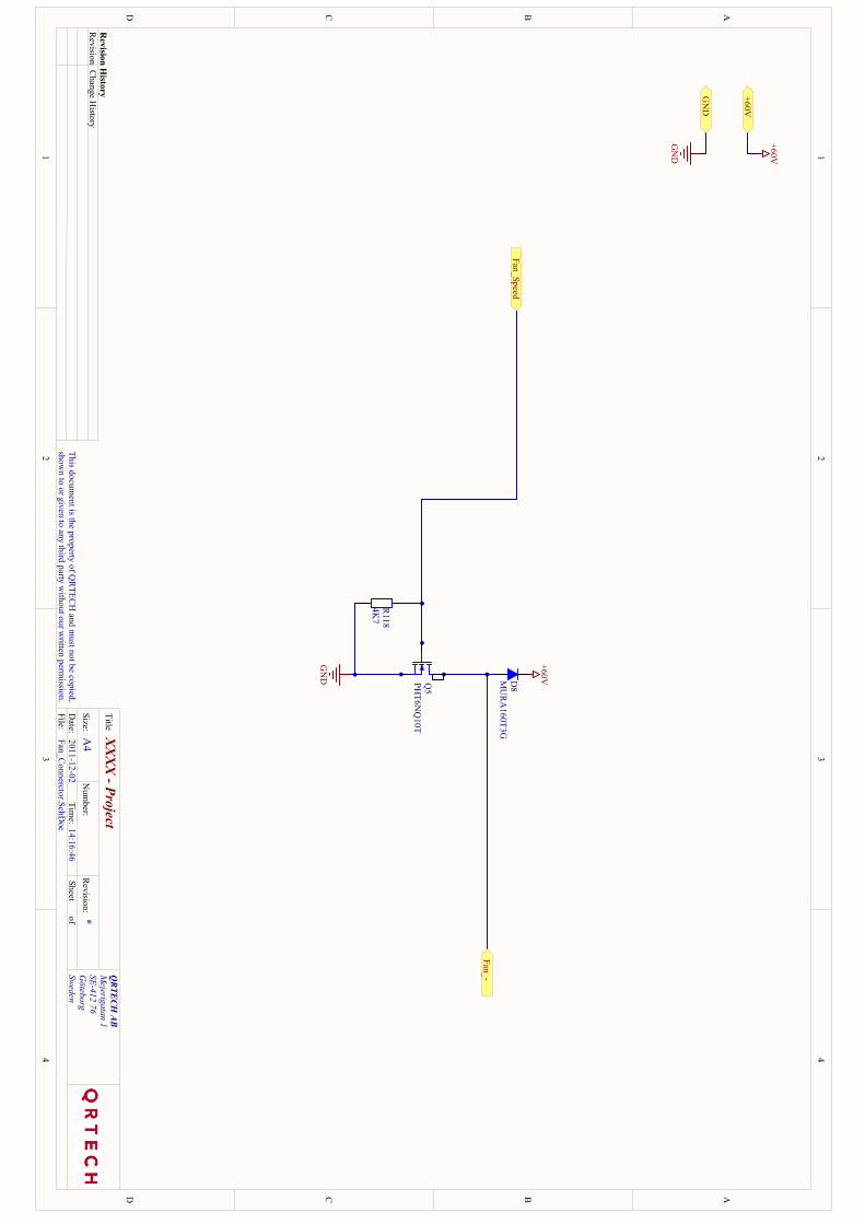
1 1
2 2
3 3
4 4
DD
CC
BB
AA
QRTECH
ABM
ejerigatan 1SE-412 76G
öteborgSweden
XX
XX
- Project*
2011-12-0214:16:46
Fan_Connerctor.SchD
oc
Title
Size:N
umber:
Date:
File:
Revision:
Sheetof
Time:
A4
This document is the property of Q
RTEC
H and m
ust not be copied,show
n to or given to any third party without our w
ritten permission.
Revision H
istoryR
evisionC
hange History
Fan_Speed
GN
D
R118
4K7
+60V
+60V
GN
D
GN
D
Fan_-
+60VD8
MU
RA
160T3G
Q5
PHT6N
Q10T
PID801 PID802COD8
PIQ501
PIQ502PIQ503 PIQ504COQ5
PIR11801 PIR11802COR118
PID802
PO060V
PIQ503
PIR11801
POGND
PID801PIQ502PIQ504
POFan00
PIQ501
PIR11802
POFan0Speed
PO060V
POFAN00
POFAN0SPEED
POGND
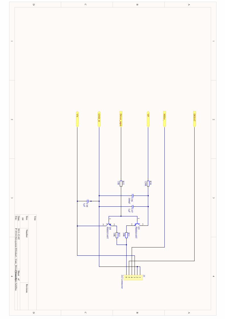
1 1
2 2
3 3
4 4
DD
CC
BB
AA
Title
Num
berR
evisionSize
A4
Date:
2011-12-02Sheet of
File:P:\9334 D
rivsystem ElG
okart\..\Gate_D
river_Connector.SchD
ocD
rawn By:
R53
10R
R51
20RR
52
11R
R50
120R
C47
1µFC
46100nFC
481µF
1
3 2Q4
PBSS5160T
1
32 Q3
PBSS4160T
3 12456
J32x3 connectorD
river_input
VP
VN
GN
D_H
DESA
T
Miller_
PIC4601 PIC4602COC46
PIC4701 PIC4702COC47
PIC4801 PIC4802COC48
PIJ301
PIJ302
PIJ303
PIJ304
PIJ305
PIJ306 COJ3
PIQ301
PIQ302 PIQ303COQ3
PIQ401
PIQ402PIQ403 COQ4
PIR5001PIR5002 C
OR50
PIR5101PIR5102
COR51
PIR5201PIR5202 C
OR52
PIR5301PIR5302
COR53
PIC4601PIC4701
PIC4802
PIJ301
PIJ302
POGND0H
PIC4602PIC4702
PIQ303
PIR5001
PIC4801
PIJ303
PIQ403
POVN
PIJ304
POMiller0
PIJ305
PODESAT
PIJ306
PIR5102
PIR5302
PIQ301
PIQ401
PIR5201
PIQ302
PIR5101
PIQ402PIR5301
PIR5002POVP
PIR5202PODriver0input
PODESAT
PODRIVER0INPUT
POGND0H
POMILLER0
POVN
POVP
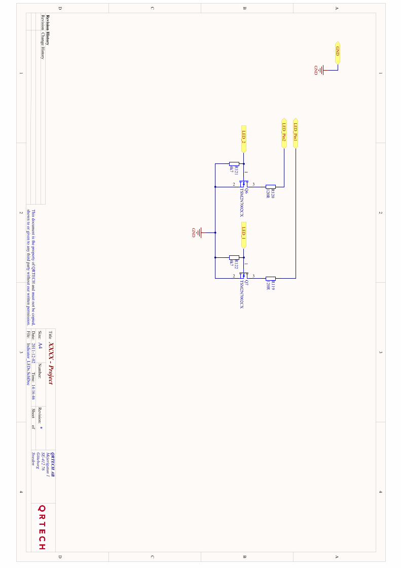
1 1
2 2
3 3
4 4
DD
CC
BB
AA
QRTECH
ABM
ejerigatan 1SE-412 76G
öteborgSweden
XX
XX
- Project*
2011-12-0214:16:46
Indicator_LEDs.SchD
oc
Title
Size:N
umber:
Date:
File:
Revision:
Sheetof
Time:
A4
This document is the property of Q
RTEC
H and m
ust not be copied,show
n to or given to any third party without our w
ritten permission.
Revision H
istoryR
evisionC
hange History
3
1
2 Q6
TSM2N
7002CX
3
1
2 Q7
TSM2N
7002CX
LED_1
LED_2
GN
D
GN
D
GN
D
R120
120RR
119120R
LED_Pin1
LED_Pin2
R121
4k7R
1224k7
PIQ601
PIQ602 PIQ603COQ6PIQ701
PIQ702 PIQ703COQ7
PIR11901 PIR11902COR119
PIR12001 PIR12002COR120
PIR12101 PIR12102COR121
PIR12201 PIR12202COR122PIQ602
PIQ702
PIR12101PIR12201
POGND
PIQ601PIR12102
POLED02
PIQ603 PIR12001
PIQ701PIR12202
POLED01
PIQ703 PIR11901 PIR11902
POLED0Pin1
PIR12002POLED0Pin2
POGND
POLED01
POLED02
POLED0PIN1
POLED0PIN2
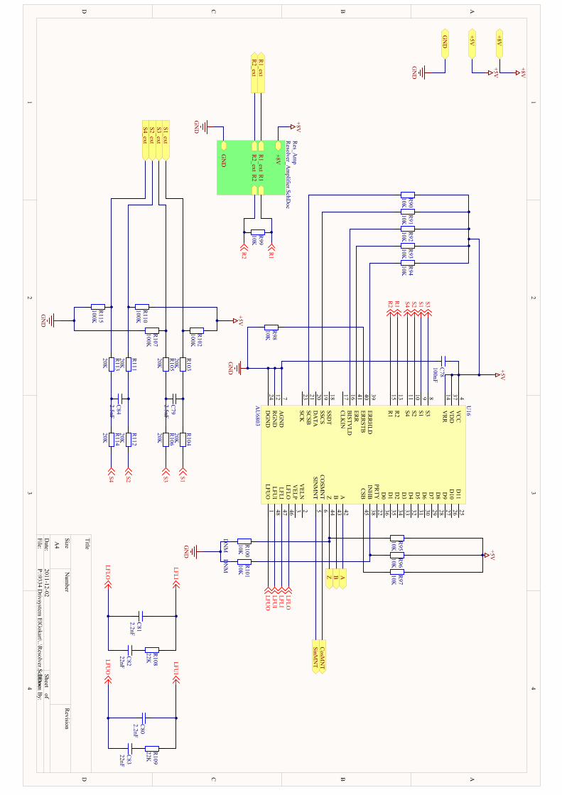
1 1
2 2
3 3
4 4
DD
CC
BB
AA
Title
Num
berR
evisionSize
A4
Date:
2011-12-02Sheet of
File:P:\9334 D
rivsystem ElG
okart\..\Resolver.SchD
ocD
rawn By:
LFUO
1
VELN
2
VELP
3
VC
C4
SINM
NT
5C
OSM
NT
6
AG
ND
7
S38
S19
S210
S411
RG
ND
12
R2
13
VR
R14
R1
15
BISTV
LD16
CLK
IN17
SSDT
18
SSCS
19
DA
TA20
SCSB
21
PRTY
22
SCK
23
DG
ND
24
D11
25
D10
26
D9
27
D8
28
D7
29
D6
30
D5
31
D4
32
D3
33
D2
34
D1
35
D0
36
VD
D37
INH
B38
ERR
HLD
39
ERR
STB40
ERR
41
A42
B43
Z44
CSB
45
LFLO46
LFLI47
LFUI
48
U16
AU
6803
DN
M R101
10K
R93
10K
GN
D
+5V
GN
D
+5V+5V
GN
D
ABZ
+5V
S3S1S2S4
R1
R2
S1S2 S3S4
R1
R2
R97
10KR
9610K
DN
M R100
10K
R92
10K
GN
D
R94
10K
R98
10K
R91
10K
C78
100nF
R108
22KR
10922K
C80
2.2nFC
8322nF
C82
22nF
C81
2.2nF
LFUO
LFUI
LFLI
LFLO
LFLOLFLILFU
ILFU
O
R90
10K
C79
2.5nF
R103
20K
R104
20KR
106
20K
R105
20K
R102
100K
R107
100K
+5V
GN
D
C84
2.5nF
R111
20K
R112
20KR
114
20K
R113
20K
R110
100K
R115
100K
R95
10K
SinMN
TC
osMN
T
S1_ext
S2_extS3_ext
S4_ext
R1_ext
R2_ext
R1
R2
+8V
GN
D
R1_ext
R2_ext
Res_A
mp
Resolver_A
mplifier.SchD
oc
GN
D
+8V
+8V
+8V
R99
10K
PIC7801 PIC7802COC78
PIC7901 PIC7902COC79
PIC8001 PIC8002COC80
PIC8101 PIC8102COC81
PIC8201 PIC8202COC82
PIC8301 PIC8302COC83
PIC8401 PIC8402COC84
PIR9001PIR9002 COR90 PIR9101PIR9102 COR91 PIR9201PIR9202 COR92 PIR9301PIR9302 COR93 PIR9401PIR9402 COR94PIR9501PIR9502 COR95 PIR9601PIR9602 COR96 PIR9701PIR9702 COR97
PIR9801PIR9802 COR98PIR9901PIR9902 COR99
PIR10001PIR10002 COR100 PIR10101PIR10102 COR101
PIR10201 PIR10202COR102
PIR10301PIR10302
COR103PIR10401
PIR10402
COR104
PIR10501PIR10502
COR105PIR10601
PIR10602
COR106
PIR10701 PIR10702COR107PIR10801PIR10802 COR108
PIR10901PIR10902 COR109
PIR11001 PIR11002COR110
PIR11101PIR11102
COR111PIR11201
PIR11202
COR112
PIR11301PIR11302
COR113PIR11401
PIR11402COR114
PIR11501 PIR11502COR115
PIU1601
PIU1602
PIU1603
PIU1604
PIU1605
PIU1606
PIU1607
PIU1608
PIU1609
PIU16010
PIU16011
PIU16012
PIU16013
PIU16014
PIU16015
PIU16016
PIU16017
PIU16018
PIU16019
PIU16020
PIU16021
PIU16022
PIU16023
PIU16024
PIU16025
PIU16026
PIU16027
PIU16028
PIU16029
PIU16030
PIU16031
PIU16032
PIU16033
PIU16034
PIU16035
PIU16036
PIU16037
PIU16038
PIU16039
PIU16040
PIU16041
PIU16042
PIU16043
PIU16044
PIU16045
PIU16046
PIU16047
PIU16048
COU16
PIC7802
PIR9001PIR9101
PIR9201PIR9301
PIR9401PIR9501
PIR9601PIR9701
PIR10202
PIR11002
PIU1604
PIU16014
PIU16037
PO05V
PO08V
PIC7801
PIR9802
PIR10002PIR10102
PIR10701
PIR11501
PIU1607
PIU16012
PIU16024
POGND
PIC8102
PIR10801
PIU16047
PIC8101PIC8201
PIU16046
PIC8002
PIR10901
PIU16048
PIC8001
PIC8301
PIU1601
PIC7901PIR10502
PIR10601
PIC7902PIR10302
PIR10401
PIC8202 PIR10802PIC8302 PIR10902
PIC8401PIR11302
PIR11401
PIC8402PIR11102
PIR11201
PIR9002
PIU16021
PIR9102
PIU16019
PIR9202
PIU16016
PIR9302
PIU16041
PIR9402
PIU16039
PIR9502PIR10001
PIU16044
POZ
PIR9602PIR10101
PIU16038
PIR9702
PIU16045
PIR9801
PIU16040
PIR10201PIR10301
POS10ext
PIR10501PIR10702
POS30ext
PIR11001PIR11101
POS20ext
PIR11301PIR11502
POS40ext
PIU1602
PIU1603
PIU1605
POSinMNT
PIU1606
POCosMNT
PIU16017
PIU16018
PIU16020
PIU16022
PIU16023
PIU16025
PIU16026
PIU16027
PIU16028
PIU16029
PIU16030
PIU16031
PIU16032
PIU16033
PIU16034
PIU16035
PIU16036
PIU16042
POA
PIU16043
POB
PIR9901
PIU16013
POR10ext
PIR9902
PIU16015
POR20ext
PIR10402
PIU1609
PIR11202
PIU16010
PIR10602
PIU1608
PIR11402
PIU16011
PO05V
PO08V
POA
POB
POCOSMNT
POGNDPOR10EXT
POR20EXT
POS10EXT
POS20EXT
POS30EXT
POS40EXT
POSINMNT
POZ
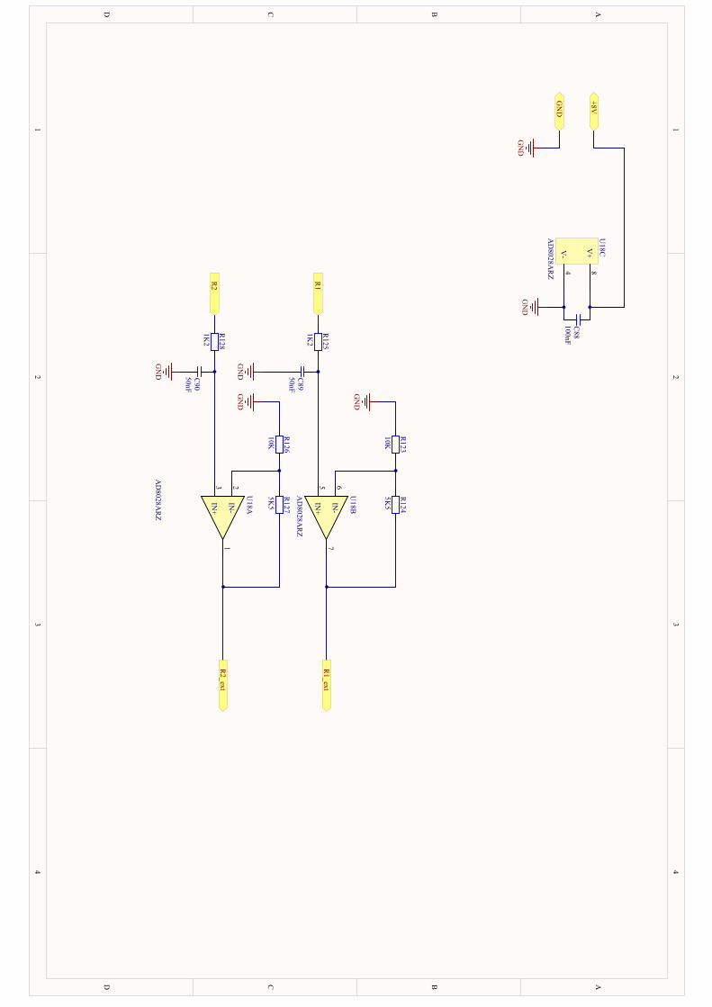
1 1
2 2
3 3
4 4
DD
CC
BB
AA
IN+
57
IN-
6
U18B
AD
8028AR
Z
IN+
31
IN-
2
U18A
AD
8028AR
Z
V+
8
V-
4
U18C
AD
8028AR
Z
R1
R2
R127
5K5
R126
10K
R123
10K
R124
5K5
GN
D
+8V
GN
D
GN
D
GN
D
R125
1K2
R128
1K2
GN
D
C89
50nF
C90
50nF
GN
D
GN
D
R1_ext
R2_ext
C88
100nFPIC8801 PIC8802COC88
PIC8901 PIC8902COC89
PIC9001 PIC9002COC90
PIR12301PIR12302
COR123PIR12401
PIR12402
COR124
PIR12501PIR12502
COR125
PIR12601PIR12602
COR126PIR12701
PIR12702
COR127
PIR12801PIR12802
COR128PIU1801
PIU1802
PIU1803 COU18A
PIU1805
PIU1806
PIU1807
COU18B
PIU1804
PIU1808
COU18C
PIC8801
PIC8901PIC9001
PIR12301
PIR12601
PIU1804
POGND
PIC8802PIU1808
PO08V
PIC8902PIR12502
PIU1805
PIC9002PIR12802
PIU1803
PIR12302PIR12401
PIU1806
PIR12402
PIU1807
POR10ext
PIR12501POR1
PIR12602PIR12701
PIU1802
PIR12702
PIU1801
POR20ext
PIR12801POR2
PO08V
POGND
POR1
POR10EXT
POR2
POR20EXT
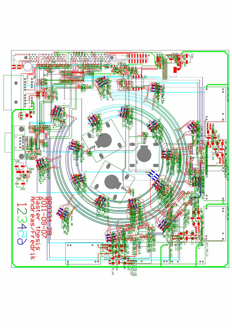
PAC102PAC101
COC1
PAC202PAC201
COC2PAC302
PAC301
COC3
PAC402PAC401
COC4
PAC502PAC501
COC5PAC602
PAC601
COC6
PAC702PAC701
COC7PAC802
PAC801
COC8PAC902
PAC901
COC9
PAC1001PAC1002
COC10
PAC1102PAC1101
COC11
PAC1202PAC1201
COC12
PAC1302PAC1301
COC13
PAC1402PAC1401
COC14
PAC1501PAC1502 COC15
PAC1602PAC1601
COC16
PAC1702PAC1701
COC17
PAC1802PAC1801
COC18PAC1902PAC1901
COC19
PAC2002PAC2001
COC20
PAC2102PAC2101
COC21
PAC2202PAC2201
COC22
PAC2301PAC2302
COC23
PAC2402PAC2401
COC24
PAC2502PAC2501
COC25
PAC2602PAC2601
COC26
PAC2702PAC2701
COC27
PAC2802PAC2801
COC28
PAC2902PAC2901
COC29
PAC3002PAC3001
COC30
PAC3102PAC3101
COC31
PAC3202PAC3201
COC32
PAC3302PAC3301
COC33
PAC3402PAC3401
COC34
PAC3502PAC3501
COC35
PAC3602PAC3601
COC36PAC3702PAC3701
COC37
PAC380GD0H101 PAC380GD0H102
COC380GD0H1
PAC380GD0H202
PAC380GD0H201
COC380GD0H2
PAC380GD0H301 PAC380GD0H302
COC380GD0H3
PAC380GD0L102PAC380GD0L101
COC380GD0L1
PAC380GD0L202
PAC380GD0L201
COC380GD0L2
PAC380GD0L301 PAC380GD0L302
COC380GD0L3
PAC390GD0H101PAC390GD0H102
COC390GD0H1
PAC390GD0H202
PAC390GD0H201
COC390GD0H2
PAC390GD0H301 PAC390GD0H302
COC390GD0H3
PAC390GD0L102PAC390GD0L101
COC390GD0L1
PAC390GD0L202
PAC390GD0L201
COC390GD0L2
PAC390GD0L301 PAC390GD0L302
COC390GD0L3
PAC400GD0H101PAC400GD0H102
COC400GD0H1
PAC400GD0H202
PAC400GD0H201
COC400GD0H2
PAC400GD0H301PAC400GD0H302
COC400GD0H3
PAC400GD0L102PAC400GD0L101
COC400GD0L1
PAC400GD0L202PAC400GD0L201
COC400GD0L2
PAC400GD0L301 PAC400GD0L302
COC400GD0L3
PAC410GD0H101PAC410GD0H102
COC410GD0H1PAC410GD0H202
PAC410GD0H201
COC410GD0H2
PAC410GD0H301PAC410GD0H302
COC410GD0H3
PAC410GD0L102PAC410GD0L101
COC410GD0L1
PAC410GD0L202PAC410GD0L201
COC410GD0L2
PAC410GD0L301 PAC410GD0L302
COC410GD0L3
PAC420GD0H101 PAC420GD0H102
COC420GD0H1
PAC420GD0H202
PAC420GD0H201
COC420GD0H2
PAC420GD0H301 PAC420GD0H302
COC420GD0H3
PAC420GD0L102PAC420GD0L101
COC420GD0L1
PAC420GD0L202PAC420GD0L201
COC420GD0L2
PAC420GD0L301PAC420GD0L302
COC420GD0L3
PAC430GD0H101PAC430GD0H102
COC430GD0H1
PAC430GD0H202
PAC430GD0H201
COC430GD0H2
PAC430GD0H301PAC430GD0H302
COC430GD0H3
PAC430GD0L102PAC430GD0L101
COC430GD0L1
PAC430GD0L202PAC430GD0L201
COC430GD0L2
PAC430GD0L301PAC430GD0L302
COC430GD0L3
PAC440GD0H101PAC440GD0H102
COC440GD0H1
PAC440GD0H202PAC440GD0H201
COC440GD0H2
PAC440GD0H301PAC440GD0H302
COC440GD0H3
PAC440GD0L102 PAC440GD0L101
COC440GD0L1
PAC440GD0L202
PAC440GD0L201
COC440GD0L2
PAC440GD0L301PAC440GD0L302
COC440GD0L3
PAC450GD0H101PAC450GD0H102
COC450GD0H1
PAC450GD0H202
PAC450GD0H201
COC450GD0H2
PAC450GD0H301PAC450GD0H302
COC450GD0H3
PAC450GD0L102PAC450GD0L101
COC450GD0L1
PAC450GD0L202PAC450GD0L201
COC450GD0L2
PAC450GD0L301
PAC450GD0L302
COC450GD0L3PAC460Gdc01102PAC460Gdc01101
COC460Gdc011
PAC460Gdc01202 PAC460Gdc01201
COC460Gdc012
PAC460Gdc01302 PAC460Gdc01301
COC460Gdc013
PAC460Gdc01402PAC460Gdc01401
COC460Gdc014
PAC460Gdc01501PAC460Gdc01502
COC460Gdc015
PAC460Gdc01602PAC460Gdc01601
COC460Gdc016
PAC460Gdc02102PAC460Gdc02101
COC460Gdc021
PAC460Gdc02202PAC460Gdc02201
COC460Gdc022
PAC460Gdc02302PAC460Gdc02301
COC460Gdc023
PAC460Gdc02402PAC460Gdc02401
COC460Gdc024 PAC460Gdc02502PAC460Gdc02501
COC460Gdc025
PAC460Gdc02602PAC460Gdc02601
COC460Gdc026
PAC460Gdc03102PAC460Gdc03101
COC460Gdc031
PAC460Gdc03202
PAC460Gdc03201
COC460Gdc032
PAC460Gdc03302PAC460Gdc03301
COC460Gdc033
PAC460Gdc03402PAC460Gdc03401
COC460Gdc034
PAC460Gdc03501PAC460Gdc03502
COC460Gdc035
PAC460Gdc03602 PAC460Gdc03601
COC460Gdc036
PAC470Gdc01101PAC470Gdc01102
COC470Gdc011
PAC470Gdc01201PAC470Gdc01202
COC470Gdc012
PAC470Gdc01301
PAC470Gdc01302
COC470Gdc013
PAC470Gdc01401
PAC470Gdc01402
COC470Gdc014
PAC470Gdc01502PAC470Gdc01501
COC470Gdc015
PAC470Gdc01601PAC470Gdc01602
COC470Gdc016
PAC470Gdc02101
PAC470Gdc02102
COC470Gdc021
PAC470Gdc02201PAC470Gdc02202
COC470Gdc022
PAC470Gdc02301PAC470Gdc02302
COC470Gdc023
PAC470Gdc02401 PAC470Gdc02402COC470Gdc024 PAC470Gdc02501
PAC470Gdc02502
COC470Gdc025
PAC470Gdc02601
PAC470Gdc02602
COC470Gdc026
PAC470Gdc03101 PAC470Gdc03102COC470Gdc031
PAC470Gdc03201
PAC470Gdc03202
COC470Gdc032
PAC470Gdc03301PAC470Gdc03302
COC470Gdc033
PAC470Gdc03401PAC470Gdc03402COC470Gdc034
PAC470Gdc03502
PAC470Gdc03501
COC470Gdc035
PAC470Gdc03601PAC470Gdc03602
COC470Gdc036
PAC480Gdc01101PAC480Gdc01102COC480Gdc011
PAC480Gdc01201PAC480Gdc01202
COC480Gdc012
PAC480Gdc01301
PAC480Gdc01302
COC480Gdc013
PAC480Gdc01401
PAC480Gdc01402
COC480Gdc014
PAC480Gdc01502PAC480Gdc01501COC480Gdc015
PAC480Gdc01601PAC480Gdc01602
COC480Gdc016
PAC480Gdc02101PAC480Gdc02102
COC480Gdc021
PAC480Gdc02201PAC480Gdc02202
COC480Gdc022
PAC480Gdc02301PAC480Gdc02302
COC480Gdc023
PAC480Gdc02401 PAC480Gdc02402
COC480Gdc024
PAC480Gdc02501PAC480Gdc02502
COC480Gdc025
PAC480Gdc02601
PAC480Gdc02602
COC480Gdc026
PAC480Gdc03101 PAC480Gdc03102COC480Gdc031
PAC480Gdc03201
PAC480Gdc03202
COC480Gdc032
PAC480Gdc03301PAC480Gdc03302
COC480Gdc033
PAC480Gdc03401PAC480Gdc03402
COC480Gdc034
PAC480Gdc03502PAC480Gdc03501
COC480Gdc035
PAC480Gdc03601PAC480Gdc03602
COC480Gdc036
PAC4902
PAC4901
COC49
PAC5002
PAC5001
COC50
PAC5102PAC5101
COC51
PAC5202PAC5201
COC52
PAC5302PAC5301
COC53
PAC5402PAC5401
COC54
PAC5502PAC5501
COC55
PAC5602PAC5601
COC56
PAC5702
PAC5701
COC57
PAC5802
PAC5801
COC58
PAC5901
PAC5902
COC59
PAC6002PAC6001
COC60PAC6102
PAC6101
COC61PAC6202 PAC6201COC62
PAC6302
PAC6301
COC63PAC6402
PAC6401
COC64
PAC6502PAC6501
COC65
PAC6602
PAC6601
COC66
PAC6702 PAC6701COC67
PAC6802PAC6801COC68
PAC6902PAC6901
COC69
PAC7002
PAC7001
COC70
PAC7101
PAC7102
COC71
PAC7202PAC7201
COC72PAC7301
PAC7302
COC73PAC7402
PAC7401
COC74
PAC7501
PAC7502
COC75
PAC7602PAC7601
COC76
PAC7701PAC7702
COC77
PAC7802PAC7801
COC78
PAC7902PAC7901
COC79PAC8002PAC8001
COC80PAC8102PAC8101
COC81PAC8202
PAC8201
COC82
PAC8302PAC8301
COC83PAC8402PAC8401
COC84
PAC850TR0H101
PAC850TR0H102
COC850TR0H1
PAC850TR0H201
PAC850TR0H202
COC850TR0H2
PAC850TR0H301PAC850TR0H302
COC850TR0H3
PAC850TR0L101PAC850TR0L102
COC850TR0L1
PAC850TR0L201
PAC850TR0L202
COC850TR0L2
PAC850TR0L301PAC850TR0L302
COC850TR0L3
PAC860TR0H102 PAC860TR0H101COC860TR0H1
PAC860TR0H202PAC860TR0H201
COC860TR0H2
PAC860TR0H302PAC860TR0H301
COC860TR0H3
PAC860TR0L102PAC860TR0L101
COC860TR0L1
PAC860TR0L202 PAC860TR0L201COC860TR0L2
PAC860TR0L302PAC860TR0L301
COC860TR0L3
PAC870TR0H101
PAC870TR0H102
COC870TR0H1
PAC870TR0H201
PAC870TR0H202
COC870TR0H2
PAC870TR0H301PAC870TR0H302
COC870TR0H3
PAC870TR0L101PAC870TR0L102
COC870TR0L1
PAC870TR0L201
PAC870TR0L202
COC870TR0L2
PAC870TR0L301PAC870TR0L302
COC870TR0L3
PAC8801PAC8802
COC88 PAC8902PAC8901COC89
PAC9002PAC9001COC90
PAD104PAD103
PAD102PAD101
COD1PAD203
PAD202PAD201
COD2
PAD303PAD302
PAD301
COD3
PAD401PAD402
COD4
PAD501
PAD502COD5
PAD60TR0H102
PAD60TR0H101
COD60TR0H1
PAD60TR0H202
PAD60TR0H201
COD60TR0H2
PAD60TR0H302PAD60TR0H301COD60TR0H3
PAD60TR0L102PAD60TR0L101
COD60TR0L1
PAD60TR0L202
PAD60TR0L201COD60TR0L2
PAD60TR0L302PAD60TR0L301
COD60TR0L3
PAD70TR0H102
PAD70TR0H101
COD70TR0H1
PAD70TR0H202
PAD70TR0H201
COD70TR0H2
PAD70TR0H302PAD70TR0H301COD70TR0H3
PAD70TR0L102PAD70TR0L101
COD70TR0L1
PAD70TR0L202
PAD70TR0L201COD70TR0L2
PAD70TR0L302PAD70TR0L301
COD70TR0L3
PAD801PAD802
COD8
PAJ1013PAJ1014
PAJ1012
PAJ1010
PAJ1011
PAJ109
PAJ108
PAJ106
PAJ107
PAJ105
PAJ101
PAJ103
PAJ102
PAJ104
COJ1
PAJ201PAJ203
PAJ202PAJ204COJ2
PAJ30Gdc01104PAJ30Gdc01102PAJ30Gdc01103
PAJ30Gdc01101
PAJ30Gdc01105PAJ30Gdc01106
COJ30Gdc011PAJ30Gdc01204PAJ30Gdc01202
PAJ30Gdc01203PAJ30Gdc01201PAJ30Gdc01205
PAJ30Gdc01206
COJ30Gdc012
PAJ30Gdc01304PAJ30Gdc01302 PAJ30Gdc01303
PAJ30Gdc01301PAJ30Gdc01305
PAJ30Gdc01306
COJ30Gdc013
PAJ30Gdc01404PAJ30Gdc01402 PAJ30Gdc01403
PAJ30Gdc01401PAJ30Gdc01405
PAJ30Gdc01406
COJ30Gdc014
PAJ30Gdc01504PAJ30Gdc01502
PAJ30Gdc01503PAJ30Gdc01501 PAJ30Gdc01505PAJ30Gdc01506
COJ30Gdc015
PAJ30Gdc01604PAJ30Gdc01602
PAJ30Gdc01603PAJ30Gdc01601
PAJ30Gdc01605PAJ30Gdc01606
COJ30Gdc016
PAJ30Gdc02104PAJ30Gdc02102 PAJ30Gdc02103
PAJ30Gdc02101PAJ30Gdc02105PAJ30Gdc02106
COJ30Gdc021
PAJ30Gdc02204PAJ30Gdc02202
PAJ30Gdc02203PAJ30Gdc02201 PAJ30Gdc02205PAJ30Gdc02206
COJ30Gdc022
PAJ30Gdc02304
PAJ30Gdc02302PAJ30Gdc02303
PAJ30Gdc02301
PAJ30Gdc02305PAJ30Gdc02306
COJ30Gdc023
PAJ30Gdc02404PAJ30Gdc02402
PAJ30Gdc02403PAJ30Gdc02401
PAJ30Gdc02405 PAJ30Gdc02406COJ30Gdc024
PAJ30Gdc02504
PAJ30Gdc02502
PAJ30Gdc02503
PAJ30Gdc02501
PAJ30Gdc02505PAJ30Gdc02506
COJ30Gdc025
PAJ30Gdc02604 PAJ30Gdc02602
PAJ30Gdc02603 PAJ30Gdc02601PAJ30Gdc02605
PAJ30Gdc02606COJ30Gdc026
PAJ30Gdc03104PAJ30Gdc03102PAJ30Gdc03103PAJ30Gdc03101
PAJ30Gdc03105 PAJ30Gdc03106COJ30Gdc031
PAJ30Gdc03204PAJ30Gdc03202
PAJ30Gdc03203PAJ30Gdc03201PAJ30Gdc03205 PAJ30Gdc03206
COJ30Gdc032
PAJ30Gdc03304 PAJ30Gdc03302PAJ30Gdc03303 PAJ30Gdc03301PAJ30Gdc03305
PAJ30Gdc03306
COJ30Gdc033
PAJ30Gdc03404 PAJ30Gdc03402PAJ30Gdc03403 PAJ30Gdc03401PAJ30Gdc03405
PAJ30Gdc03406
COJ30Gdc034
PAJ30Gdc03504PAJ30Gdc03502PAJ30Gdc03503PAJ30Gdc03501
PAJ30Gdc03505 PAJ30Gdc03506COJ30Gdc035
PAJ30Gdc03604PAJ30Gdc03602
PAJ30Gdc03603PAJ30Gdc03601PAJ30Gdc03605
PAJ30Gdc03606
COJ30Gdc036
PAJ404PAJ402
PAJ403PAJ401PAJ405PAJ406 COJ4
PAJ50
PAJ508PAJ506
PAJ502PAJ503
PAJ505PAJ507
PAJ504
PAJ5014PAJ5018
PAJ5017PAJ5012
PAJ5013
PAJ501
PAJ5015PAJ5016
PAJ5011PAJ5010PAJ509
COJ5
PAJ601PAJ606 PAJ602PAJ607 PAJ603PAJ608 PAJ604PAJ609 PAJ605PAJ6010
PAJ6011
COJ6
PAL103PAL102
PAL104PAL101
COL1
PAL202
PAL201COL2
PAL301PAL302
COL3
PAQ103PAQ102PAQ101
COQ1
PAQ20GD0H101PAQ20GD0H102PAQ20GD0H103
COQ20GD0H1
PAQ20GD0H203PAQ20GD0H202PAQ20GD0H201
COQ20GD0H2
PAQ20GD0H301
PAQ20GD0H302 PAQ20GD0H303
COQ20GD0H3
PAQ20GD0L103PAQ20GD0L102PAQ20GD0L101
COQ20GD0L1
PAQ20GD0L203 PAQ20GD0L202
PAQ20GD0L201
COQ20GD0L2
PAQ20GD0L301PAQ20GD0L302
PAQ20GD0L303
COQ20GD0L3
PAQ30Gdc01103 PAQ30Gdc01102
PAQ30Gdc01101
COQ30Gdc011
PAQ30Gdc01203 PAQ30Gdc01202PAQ30Gdc01201
COQ30Gdc012
PAQ30Gdc01303
PAQ30Gdc01302PAQ30Gdc01301
COQ30Gdc013
PAQ30Gdc01403PAQ30Gdc01402
PAQ30Gdc01401
COQ30Gdc014
PAQ30Gdc01501PAQ30Gdc01502PAQ30Gdc01503
COQ30Gdc015
PAQ30Gdc01603PAQ30Gdc01602
PAQ30Gdc01601
COQ30Gdc016
PAQ30Gdc02103PAQ30Gdc02102 PAQ30Gdc02101
COQ30Gdc021
PAQ30Gdc02203PAQ30Gdc02202 PAQ30Gdc02201
COQ30Gdc022
PAQ30Gdc02303
PAQ30Gdc02302
PAQ30Gdc02301
COQ30Gdc023
PAQ30Gdc02403PAQ30Gdc02402
PAQ30Gdc02401
COQ30Gdc024
PAQ30Gdc02503
PAQ30Gdc02502
PAQ30Gdc02501
COQ30Gdc025
PAQ30Gdc02603PAQ30Gdc02602PAQ30Gdc02601
COQ30Gdc026
PAQ30Gdc03103PAQ30Gdc03102
PAQ30Gdc03101
COQ30Gdc031
PAQ30Gdc03203PAQ30Gdc03202PAQ30Gdc03201
COQ30Gdc032
PAQ30Gdc03303PAQ30Gdc03302PAQ30Gdc03301
COQ30Gdc033
PAQ30Gdc03403PAQ30Gdc03402PAQ30Gdc03401
COQ30Gdc034
PAQ30Gdc03501PAQ30Gdc03502PAQ30Gdc03503
COQ30Gdc035
PAQ30Gdc03603 PAQ30Gdc03602PAQ30Gdc03601
COQ30Gdc036
PAQ40Gdc01103 PAQ40Gdc01102
PAQ40Gdc01101
COQ40Gdc011
PAQ40Gdc01203
PAQ40Gdc01202PAQ40Gdc01201
COQ40Gdc012
PAQ40Gdc01303
PAQ40Gdc01302PAQ40Gdc01301
COQ40Gdc013
PAQ40Gdc01403
PAQ40Gdc01402PAQ40Gdc01401
COQ40Gdc014
PAQ40Gdc01501PAQ40Gdc01502PAQ40Gdc01503
COQ40Gdc015
PAQ40Gdc01603PAQ40Gdc01602
PAQ40Gdc01601
COQ40Gdc016
PAQ40Gdc02103PAQ40Gdc02102 PAQ40Gdc02101
COQ40Gdc021
PAQ40Gdc02203PAQ40Gdc02202 PAQ40Gdc02201
COQ40Gdc022
PAQ40Gdc02303
PAQ40Gdc02302
PAQ40Gdc02301
COQ40Gdc023
PAQ40Gdc02403PAQ40Gdc02402
PAQ40Gdc02401
COQ40Gdc024
PAQ40Gdc02503
PAQ40Gdc02502
PAQ40Gdc02501
COQ40Gdc025
PAQ40Gdc02603PAQ40Gdc02602PAQ40Gdc02601
COQ40Gdc026
PAQ40Gdc03103PAQ40Gdc03102
PAQ40Gdc03101
COQ40Gdc031
PAQ40Gdc03203PAQ40Gdc03202PAQ40Gdc03201
COQ40Gdc032
PAQ40Gdc03303PAQ40Gdc03302PAQ40Gdc03301
COQ40Gdc033
PAQ40Gdc03403PAQ40Gdc03402
PAQ40Gdc03401
COQ40Gdc034
PAQ40Gdc03501PAQ40Gdc03502
PAQ40Gdc03503
COQ40Gdc035
PAQ40Gdc03603 PAQ40Gdc03602PAQ40Gdc03601
COQ40Gdc036
PAQ501PAQ502
PAQ503
PAQ504COQ5
PAQ603PAQ602
PAQ601
COQ6
PAQ703PAQ702
PAQ701
COQ7PAR102
PAR101
COR1
PAR202
PAR201
COR2PAR302PAR301
COR3 PAR402
PAR401
COR4PAR502
PAR501
COR5
PAR602PAR601
COR6
PAR702
PAR701
COR7PAR802
PAR801
COR8
PAR902
PAR901
COR9PAR1002
PAR1001
COR10
PAR1102
PAR1101
COR11 PAR1202PAR1201
COR12
PAR1302
PAR1301
COR13
PAR1402
PAR1401
COR14
PAR1502PAR1501
COR15
PAR1602PAR1601
COR16
PAR1702
PAR1701
COR17
PAR1802
PAR1801
COR18
PAR1902
PAR1901
COR19
PAR2002PAR2001
COR20PAR2102PAR2101
COR21
PAR2202PAR2201
COR22PAR2302
PAR2301
COR23
PAR2402PAR2401
COR24
PAR2502PAR2501
COR25
PAR2602PAR2601
COR26
PAR2702PAR2701 COR27
PAR2802PAR2801
COR28
PAR2902PAR2901
COR29
PAR3002PAR3001
COR30
PAR3102PAR3101
COR31
PAR3202PAR3201
COR32
PAR3302PAR3301
COR33
PAR3402PAR3401
COR34PAR3502
PAR3501
COR35
PAR3602PAR3601COR36
PAR3702PAR3701
COR37
PAR3802PAR3801
COR38
PAR3902PAR3901
COR39
PAR4002PAR4001
COR40
PAR4101PAR4102
COR41PAR4202
PAR4201
COR42
PAR430GD0H102PAR430GD0H101
COR430GD0H1
PAR430GD0H202
PAR430GD0H201
COR430GD0H2
PAR430GD0H302PAR430GD0H301
COR430GD0H3
PAR430GD0L102PAR430GD0L101
COR430GD0L1
PAR430GD0L202
PAR430GD0L201
COR430GD0L2
PAR430GD0L302PAR430GD0L301
COR430GD0L3
PAR440GD0H102PAR440GD0H101
COR440GD0H1
PAR440GD0H202
PAR440GD0H201
COR440GD0H2
PAR440GD0H302PAR440GD0H301
COR440GD0H3
PAR440GD0L102PAR440GD0L101
COR440GD0L1
PAR440GD0L202
PAR440GD0L201
COR440GD0L2
PAR440GD0L302PAR440GD0L301
COR440GD0L3
PAR450GD0H102PAR450GD0H101
COR450GD0H1
PAR450GD0H202
PAR450GD0H201
COR450GD0H2
PAR450GD0H302PAR450GD0H301
COR450GD0H3
PAR450GD0L102PAR450GD0L101
COR450GD0L1
PAR450GD0L202
PAR450GD0L201
COR450GD0L2
PAR450GD0L302PAR450GD0L301
COR450GD0L3
PAR460GD0H102PAR460GD0H101
COR460GD0H1
PAR460GD0H202
PAR460GD0H201
COR460GD0H2
PAR460GD0H302PAR460GD0H301
COR460GD0H3
PAR460GD0L102PAR460GD0L101
COR460GD0L1
PAR460GD0L202PAR460GD0L201
COR460GD0L2
PAR460GD0L302
PAR460GD0L301
COR460GD0L3
PAR470GD0H102 PAR470GD0H101
COR470GD0H1
PAR470GD0H202
PAR470GD0H201
COR470GD0H2
PAR470GD0H302 PAR470GD0H301
COR470GD0H3
PAR470GD0L102PAR470GD0L101
COR470GD0L1
PAR470GD0L202PAR470GD0L201
COR470GD0L2
PAR470GD0L302
PAR470GD0L301
COR470GD0L3
PAR480GD0H102PAR480GD0H101
COR480GD0H1
PAR480GD0H202
PAR480GD0H201
COR480GD0H2
PAR480GD0H302PAR480GD0H301
COR480GD0H3
PAR480GD0L102PAR480GD0L101
COR480GD0L1
PAR480GD0L202PAR480GD0L201 COR480GD0L2
PAR480GD0L302
PAR480GD0L301
COR480GD0L3
PAR490GD0H102 PAR490GD0H101
COR490GD0H1
PAR490GD0H202
PAR490GD0H201
COR490GD0H2
PAR490GD0H302 PAR490GD0H301
COR490GD0H3
PAR490GD0L102PAR490GD0L101
COR490GD0L1
PAR490GD0L202PAR490GD0L201
COR490GD0L2
PAR490GD0L302
PAR490GD0L301
COR490GD0L3
PAR500Gdc01102PAR500Gdc01101
COR500Gdc011
PAR500Gdc01202 PAR500Gdc01201
COR500Gdc012
PAR500Gdc01302 PAR500Gdc01301
COR500Gdc013
PAR500Gdc01401
PAR500Gdc01402
COR500Gdc014
PAR500Gdc01502PAR500Gdc01501
COR500Gdc015
PAR500Gdc01602PAR500Gdc01601
COR500Gdc016
PAR500Gdc02102
PAR500Gdc02101
COR500Gdc021
PAR500Gdc02202PAR500Gdc02201
COR500Gdc022
PAR500Gdc02302PAR500Gdc02301
COR500Gdc023
PAR500Gdc02402PAR500Gdc02401
COR500Gdc024
PAR500Gdc02502PAR500Gdc02501
COR500Gdc025
PAR500Gdc02601
PAR500Gdc02602
COR500Gdc026
PAR500Gdc03102PAR500Gdc03101
COR500Gdc031
PAR500Gdc03202
PAR500Gdc03201
COR500Gdc032
PAR500Gdc03302PAR500Gdc03301
COR500Gdc033
PAR500Gdc03402PAR500Gdc03401
COR500Gdc034
PAR500Gdc03502PAR500Gdc03501
COR500Gdc035
PAR500Gdc03602 PAR500Gdc03601
COR500Gdc036
PAR510Gdc01101PAR510Gdc01102
COR510Gdc011
PAR510Gdc01201 PAR510Gdc01202COR510Gdc012
PAR510Gdc01301 PAR510Gdc01302
COR510Gdc013
PAR510Gdc01401
PAR510Gdc01402
COR510Gdc014
PAR510Gdc01502PAR510Gdc01501
COR510Gdc015
PAR510Gdc01601PAR510Gdc01602COR510Gdc016
PAR510Gdc02101PAR510Gdc02102
COR510Gdc021
PAR510Gdc02201PAR510Gdc02202
COR510Gdc022
PAR510Gdc02301PAR510Gdc02302
COR510Gdc023
PAR510Gdc02401PAR510Gdc02402
COR510Gdc024 PAR510Gdc02501
PAR510Gdc02502
COR510Gdc025
PAR510Gdc02601
PAR510Gdc02602
COR510Gdc026
PAR510Gdc03101PAR510Gdc03102
COR510Gdc031
PAR510Gdc03201
PAR510Gdc03202
COR510Gdc032
PAR510Gdc03301PAR510Gdc03302
COR510Gdc033
PAR510Gdc03401PAR510Gdc03402
COR510Gdc034
PAR510Gdc03502 PAR510Gdc03501
COR510Gdc035
PAR510Gdc03601 PAR510Gdc03602COR510Gdc036
PAR520Gdc01102
PAR520Gdc01101
COR520Gdc011
PAR520Gdc01202PAR520Gdc01201
COR520Gdc012
PAR520Gdc01302PAR520Gdc01301
COR520Gdc013
PAR520Gdc01401PAR520Gdc01402
COR520Gdc014
PAR520Gdc01502PAR520Gdc01501
COR520Gdc015
PAR520Gdc01602PAR520Gdc01601
COR520Gdc016
PAR520Gdc02102PAR520Gdc02101
COR520Gdc021
PAR520Gdc02202PAR520Gdc02201
COR520Gdc022
PAR520Gdc02302
PAR520Gdc02301
COR520Gdc023
PAR520Gdc02402
PAR520Gdc02401
COR520Gdc024
PAR520Gdc02502
PAR520Gdc02501
COR520Gdc025
PAR520Gdc02601PAR520Gdc02602
COR520Gdc026
PAR520Gdc03102PAR520Gdc03101
COR520Gdc031PAR520Gdc03202PAR520Gdc03201
COR520Gdc032
PAR520Gdc03302 PAR520Gdc03301
COR520Gdc033
PAR520Gdc03402 PAR520Gdc03401
COR520Gdc034
PAR520Gdc03502PAR520Gdc03501
COR520Gdc035
PAR520Gdc03602PAR520Gdc03601
COR520Gdc036
PAR530Gdc01101PAR530Gdc01102
COR530Gdc011
PAR530Gdc01201PAR530Gdc01202
COR530Gdc012
PAR530Gdc01301
PAR530Gdc01302
COR530Gdc013
PAR530Gdc01401
PAR530Gdc01402
COR530Gdc014
PAR530Gdc01502PAR530Gdc01501COR530Gdc015
PAR530Gdc01601PAR530Gdc01602
COR530Gdc016
PAR530Gdc02101
PAR530Gdc02102
COR530Gdc021
PAR530Gdc02201PAR530Gdc02202
COR530Gdc022
PAR530Gdc02301PAR530Gdc02302
COR530Gdc023
PAR530Gdc02401 PAR530Gdc02402COR530Gdc024
PAR530Gdc02501PAR530Gdc02502
COR530Gdc025
PAR530Gdc02601
PAR530Gdc02602
COR530Gdc026
PAR530Gdc03101 PAR530Gdc03102COR530Gdc031
PAR530Gdc03201
PAR530Gdc03202
COR530Gdc032
PAR530Gdc03301PAR530Gdc03302COR530Gdc033
PAR530Gdc03401PAR530Gdc03402
COR530Gdc034
PAR530Gdc03502PAR530Gdc03501
COR530Gdc035
PAR530Gdc03601PAR530Gdc03602
COR530Gdc036
PAR5402PAR5401
COR54PAR5502
PAR5501
COR55
PAR5602
PAR5601
COR56
PAR5702PAR5701
COR57
PAR5802
PAR5801
COR58
PAR5902PAR5901
COR59
PAR6002PAR6001
COR60
PAR6102
PAR6101
COR61
PAR6202
PAR6201
COR62
PAR6302PAR6301
COR63
PAR6402PAR6401
COR64
PAR6502PAR6501
COR65
PAR6602PAR6601
COR66
PAR6702PAR6701
COR67
PAR6802PAR6801
COR68
PAR6902PAR6901
COR69PAR7002
PAR7001
COR70
PAR7102PAR7101
COR71PAR7202
PAR7201
COR72PAR7302
PAR7301
COR73PAR7402
PAR7401
COR74PAR7502
PAR7501
COR75PAR7602
PAR7601
COR76PAR7702
PAR7701
COR77
PAR7802PAR7801
COR78
PAR7902PAR7901
COR79
PAR8002PAR8001
COR80
PAR8102
PAR8101
COR81PAR8202
PAR8201
COR82PAR8302
PAR8301
COR83PAR8402
PAR8401
COR84
PAR8502PAR8501
COR85
PAR8601PAR8602
COR86PAR8701
PAR8702
COR87
PAR8801PAR8802
COR88
PAR8902
PAR8901
COR89
PAR9002PAR9001
COR90
PAR9102PAR9101
COR91
PAR9202PAR9201
COR92PAR9302
PAR9301
COR93PAR9402
PAR9401
COR94
PAR9502PAR9501
COR95
PAR9602PAR9601
COR96
PAR9702PAR9701
COR97
PAR9802PAR9801
COR98
PAR9902PAR9901
COR99PAR10002
PAR10001
COR100PAR10102
PAR10101
COR101
PAR10202
PAR10201
COR102PAR10302
PAR10301
COR103PAR10402
PAR10401
COR104
PAR10502
PAR10501
COR105
PAR10602
PAR10601
COR106
PAR10702
PAR10701
COR107
PAR10802PAR10801
COR108
PAR10902PAR10901
COR109
PAR11002
PAR11001
COR110PAR11102
PAR11101
COR111PAR11202
PAR11201
COR112
PAR11302
PAR11301
COR113PAR11402
PAR11401
COR114
PAR11502
PAR11501
COR115
PAR1160TR0H101
PAR1160TR0H102
COR1160TR0H1
PAR1160TR0H201
PAR1160TR0H202
COR1160TR0H2
PAR1160TR0H301PAR1160TR0H302
COR1160TR0H3
PAR1160TR0L101PAR1160TR0L102
COR1160TR0L1
PAR1160TR0L201
PAR1160TR0L202
COR1160TR0L2
PAR1160TR0L301PAR1160TR0L302
COR1160TR0L3
PAR1170TR0H101
PAR1170TR0H102
COR1170TR0H1
PAR1170TR0H201
PAR1170TR0H202
COR1170TR0H2
PAR1170TR0H301PAR1170TR0H302 COR1170TR0H3
PAR1170TR0L101PAR1170TR0L102
COR1170TR0L1
PAR1170TR0L201
PAR1170TR0L202
COR1170TR0L2
PAR1170TR0L301PAR1170TR0L302
COR1170TR0L3
PAR11802PAR11801
COR118
PAR11902PAR11901
COR119PAR12002PAR12001
COR120
PAR12102PAR12101
COR121PAR12202PAR12201
COR122
PAR12301
PAR12302
COR123 PAR12401
PAR12402
COR124 PAR12501PAR12502COR125
PAR12601
PAR12602
COR126 PAR12701
PAR12702
COR127
PAR12801PAR12802COR128
PATP101
COTP1PATP201
COTP2PATP301
COTP3PATP401
COTP4
PATP501
COTP5
PAU101PAU102
PAU103PAU104
PAU108PAU107
PAU106PAU105
COU1
PAU208
PAU207
PAU206
PAU205PAU204
PAU203
PAU202PAU201
COU2
PAU301PAU302PAU303PAU304
PAU308PAU307PAU306PAU305
COU3
PAU405
PAU404PAU403PAU402
PAU401
COU4PAU501PAU502
PAU503PAU504
PAU508PAU507
PAU506PAU505
COU5
PAU603
PAU601
PAU605PAU602
PAU604
PAU6011
PAU609
PAU607
PAU606
PAU6053
PAU6051PAU6052
PAU6054
PAU6056PAU6055
PAU6013
PAU6017
PAU6015PAU608
PAU6010
PAU6012
PAU6019
PAU6021PAU6014
PAU6016
PAU6018
PAU6020
PAU6022PAU6072
PAU6070
PAU6068
PAU6066
PAU6064
PAU6071
PAU6069
PAU6062
PAU6060
PAU6058
PAU6065
PAU6067
PAU6063
PAU6057
PAU6059
PAU6061
PAU6029
PAU6033PAU6024
PAU6092
PAU6096
PAU6094
PAU6035
PAU6037
PAU6039
PAU6098
PAU60100
PAU6041
PAU6043
PAU6045
PAU6047
PAU6049 PAU6050
PAU6046
PAU6042
PAU6040
PAU6028
PAU6048
PAU6044
PAU6038
PAU6036
PAU6034
PAU6027
PAU6031
PAU6025 PAU6026
PAU6030
PAU6032
PAU6090
PAU6088
PAU6084
PAU6086
PAU6082
PAU6080
PAU6078
PAU6074
PAU6076
PAU6099
PAU6097
PAU6093
PAU6095
PAU6091
PAU6089
PAU6087
PAU6083
PAU6085
PAU6081
PAU6079
PAU6077
PAU6075
PAU6023PAU6073PAU60
COU6
PAU70GD0H101
PAU70GD0H1016
PAU70GD0H102PAU70GD0H103PAU70GD0H104PAU70GD0H105PAU70GD0H106PAU70GD0H107PAU70GD0H108
PAU70GD0H1015PAU70GD0H1014PAU70GD0H1013PAU70GD0H1012PAU70GD0H1011PAU70GD0H1010PAU70GD0H109
COU70GD0H1
PAU70GD0H209PAU70GD0H2010
PAU70GD0H2011PAU70GD0H2012
PAU70GD0H2013PAU70GD0H2014
PAU70GD0H2015
PAU70GD0H208PAU70GD0H207
PAU70GD0H206PAU70GD0H205
PAU70GD0H204PAU70GD0H203
PAU70GD0H202
PAU70GD0H2016PAU70GD0H201
COU70GD0H2
PAU70GD0H301
PAU70GD0H3016
PAU70GD0H302
PAU70GD0H303PAU70GD0H304PAU70GD0H305PAU70GD0H306PAU70GD0H307
PAU70GD0H308
PAU70GD0H3015PAU70GD0H3014
PAU70GD0H3013PAU70GD0H3012
PAU70GD0H3011PAU70GD0H3010PAU70GD0H309
COU70GD0H3
PAU70GD0L109PAU70GD0L1010
PAU70GD0L1011PAU70GD0L1012
PAU70GD0L1013PAU70GD0L1014
PAU70GD0L1015
PAU70GD0L108PAU70GD0L107
PAU70GD0L106PAU70GD0L105
PAU70GD0L104PAU70GD0L103
PAU70GD0L102
PAU70GD0L1016
PAU70GD0L101
COU70GD0L1
PAU70GD0L209PAU70GD0L2010
PAU70GD0L2011PAU70GD0L2012
PAU70GD0L2013PAU70GD0L2014
PAU70GD0L2015
PAU70GD0L208PAU70GD0L207
PAU70GD0L206PAU70GD0L205
PAU70GD0L204PAU70GD0L203
PAU70GD0L202
PAU70GD0L2016PAU70GD0L201 COU70GD0L2
PAU70GD0L301
PAU70GD0L3016
PAU70GD0L302PAU70GD0L303PAU70GD0L304PAU70GD0L305PAU70GD0L306PAU70GD0L307
PAU70GD0L308
PAU70GD0L3015PAU70GD0L3014PAU70GD0L3013
PAU70GD0L3012
PAU70GD0L3011PAU70GD0L3010PAU70GD0L309
COU70GD0L3
PAU80 PAU802PAU803 PAU801
PAU806
PAU807
PAU804
PAU805
COU8
PAU90PAU902PAU903
PAU901
PAU906
PAU907PAU904
PAU905COU9
PAU100PAU1002PAU1003PAU1001
PAU1006
PAU1007
PAU1004
PAU1005
COU10
PAU11048PAU11047PAU11046PAU11045PAU11044PAU11043PAU11042PAU11041PAU11040PAU11039PAU11038PAU11037PAU11036PAU11035PAU11034PAU11033PAU11032PAU11031PAU11030PAU11029PAU11028PAU11027PAU11026PAU11025
PAU11024
PAU11023PAU11022
PAU11021PAU11020PAU11019
PAU11018PAU11017PAU11016
PAU11015PAU11014PAU11013
PAU11012PAU11011PAU11010
PAU1109PAU1108
PAU1107PAU1106PAU1105
PAU1104PAU1103PAU1102
PAU1101
COU11
PAU1209
PAU12010PAU12011PAU12012PAU12013
PAU12014PAU12015PAU12016
PAU1208
PAU1207
PAU1206PAU1205PAU1204
PAU1203
PAU1202PAU1201PAU12017
COU12
PAU1309PAU1308PAU1307
PAU1306PAU1305
PAU1304PAU1303PAU1302PAU1301
COU13
PAU1405
PAU1404PAU1403
PAU1402PAU1401
COU14
PAU1505
PAU1504PAU1503PAU1502PAU1501
COU15
PAU1601PAU1602PAU1603PAU1604PAU1605PAU1606PAU1607PAU1608PAU1609PAU16010PAU16011PAU16012PAU16013PAU16014PAU16015PAU16016PAU16017PAU16018PAU16019PAU16020PAU16021PAU16022PAU16023PAU16024
PAU16025PAU16026
PAU16027PAU16028PAU16029PAU16030
PAU16031PAU16032PAU16033
PAU16034PAU16035PAU16036
PAU16037
PAU16038
PAU16039PAU16040
PAU16041
PAU16042PAU16043
PAU16044
PAU16045PAU16046
PAU16047
PAU16048
COU16
PAU170TR0H1023
PAU170TR0H101PAU170TR0H1011PAU170TR0H1012
PAU170TR0H1013PAU170TR0H1015
PAU170TR0H1024
COU170TR0H1
PAU170TR0H2023
PAU170TR0H201PAU170TR0H2011PAU170TR0H2012
PAU170TR0H2013PAU170TR0H2015
PAU170TR0H2024
COU170TR0H2
PAU170TR0H3023
PAU170TR0H301
PAU170TR0H3011
PAU170TR0H3012PAU170TR0H3013
PAU170TR0H3015
PAU170TR0H3024
COU170TR0H3
PAU170TR0L1023
PAU170TR0L101
PAU170TR0L1011PAU170TR0L1012
PAU170TR0L1013
PAU170TR0L1015
PAU170TR0L1024
COU170TR0L1PAU170TR0L2023
PAU170TR0L201PAU170TR0L2011
PAU170TR0L2012
PAU170TR0L2013PAU170TR0L2015
PAU170TR0L2024
COU170TR0L2
PAU170TR0L3023
PAU170TR0L301
PAU170TR0L3011
PAU170TR0L3012PAU170TR0L3013
PAU170TR0L3015
PAU170TR0L3024
COU170TR0L3
PAU1801
PAU1802
PAU1803
PAU1804
PAU1808
PAU1807
PAU1806
PAU1805
COU18
PAC601
PAC2302
PAC7302
PAU405
PAU6066
PAU1405
PAC1001
PAC5602
PAC5902
PAC7702
PAJ105
PAJ404
PAR1301
PAR1401
PAU507PAU11031
PAU11042
PAU1505
PAC4902
PAC5102
PAC5302
PAC6901PAC7102
PAR3602
PAR8502
PAU803
PAU903PAU1003
PAU1401
PAC101
PAC1502PAC1602PAC1702
PAC1802
PAC1902
PAC2002
PAC380GD0H102
PAC380GD0H202
PAC380GD0H302
PAC380GD0L102
PAC380GD0L202
PAC380GD0L302
PAC390GD0H102
PAC390GD0H202
PAC390GD0H302
PAC390GD0L102
PAC390GD0L202
PAC390GD0L302
PAC5502
PAC6202
PAC6702
PAC7802
PAJ509
PAL202
PAL301
PAR102
PAR430GD0H102
PAR430GD0H202
PAR430GD0H302
PAR430GD0L102
PAR430GD0L202
PAR430GD0L302
PAR440GD0H102
PAR440GD0H202
PAR440GD0H302
PAR440GD0L102
PAR440GD0L202
PAR440GD0L302
PAR450GD0H102
PAR450GD0H202
PAR450GD0H302
PAR450GD0L102
PAR450GD0L202
PAR450GD0L302
PAR6002
PAR6102
PAR8102
PAR8501
PAR8901
PAR9001PAR9101
PAR9201
PAR9301
PAR9401
PAR9501
PAR9601
PAR9701
PAR10202PAR11002
PAU103
PAU6077
PAU6082
PAU6087
PAU6092
PAU6096
PAU70GD0H1015
PAU70GD0H2015
PAU70GD0H3015
PAU70GD0L1015
PAU70GD0L2015
PAU70GD0L3015
PAU1107
PAU11018
PAU12011
PAU1303PAU1306
PAU1604
PAU16014
PAU16037
PAC6802
PAC8802PAD502PAR8602
PAU1808
PAC702
PAC1102
PAC430GD0L102
PAC850TR0L102
PAC860TR0L102
PAD60TR0L102
PAR500Gdc01402
PAR500Gdc02402
PAR500Gdc03402
PAR1160TR0L101PAR1170TR0L101
PAU202
PAU304
PAU70GD0L105
PAC6102
PAD802PAJ502
PAJ503
PAU1203
PAU170TR0H101PAU170TR0H201
PAU170TR0H301
PAU170TR0L101
PAU170TR0L201
PAU170TR0L301
PAJ201
PAU601PAU6051
PAR3702
PAU6063
PAC602
PAC1301
PAC2101
PAC2301
PAC2401
PAC2501
PAC2601
PAC2701
PAC2901
PAC3401
PAC4901PAC5001
PAC5101PAC5201
PAC5301
PAC5401
PAC6902
PAC7101PAC7202
PAC7301
PAR3802
PAR5501
PAR5701
PAR5901
PAR8801
PAU205
PAU402PAU403
PAU608
PAU6010
PAU6012
PAU6014
PAU6016
PAU6058
PAU6060
PAU6062
PAU6064
PAU802PAU804
PAU805
PAU806
PAU807
PAU902PAU904
PAU905PAU906
PAU907
PAU1002
PAU1004
PAU1005
PAU1006
PAU1007
PAU1402
PAU1403
PAC3702
PAR4201PAU6017
PAR202
PAU6044
PAR502
PAU6095
PAR402
PAU6094
PAC3602PAR4001
PAR4102
PAU6015
PAC1302
PAR2101
PAU6071
PAQ101PAR2001
PAU6080
PAJ1013
PAU60100
PAJ1014
PAU6050
PAC3202PAR3301
PAU6040PAC3002
PAR3101PAU6090
PAC3502PAR3901
PAU6091
PAC3102PAR3202
PAU6013
PAC2802PAR2902
PAU6021
PAD801PAJ501
PAQ502
PAQ504
PAQ501PAR11802
PAU6028
PAC102
PAC201PAC301
PAC1002PAC1201
PAC1401 PAC1501PAC1601PAC1701
PAC1801
PAC1901
PAC2001
PAC2201
PAC2801
PAC3001
PAC3101
PAC3201
PAC3301
PAC3501
PAC3601
PAC3701
PAC380GD0H101
PAC380GD0H201
PAC380GD0H301
PAC380GD0L101
PAC380GD0L201
PAC380GD0L301
PAC390GD0H101
PAC390GD0H201
PAC390GD0H301
PAC390GD0L101
PAC390GD0L201
PAC390GD0L301
PAC5501
PAC5601
PAC5701PAC5801
PAC5901
PAC6101
PAC6201PAC6402
PAC6502
PAC6602
PAC6701
PAC6801
PAC7002
PAC7402
PAC7501PAC7602
PAC7701
PAC7801
PAC8801
PAC8901PAC9001
PAD201
PAD303
PAJ104
PAJ108
PAJ1010
PAJ1012
PAJ401
PAJ504PAJ505
PAJ506
PAJ5012
PAJ6010PAJ6011
PAQ102
PAQ503
PAQ602PAQ702
PAR1802
PAR2002PAR3501
PAR4101
PAR6901
PAR7001
PAR7101
PAR7201PAR7301
PAR7401PAR7501PAR7601
PAR7701
PAR7801
PAR7901
PAR8001
PAR8301PAR8401
PAR8702
PAR8802
PAR9802
PAR10002
PAR10102
PAR10701PAR11501
PAR11801
PAR12101PAR12201
PAR12301PAR12601
PAU102
PAU504
PAU6027
PAU6037
PAU6047
PAU70GD0H109
PAU70GD0H1016
PAU70GD0H209PAU70GD0H2016
PAU70GD0H309
PAU70GD0H3016
PAU70GD0L109
PAU70GD0L1016
PAU70GD0L209PAU70GD0L2016
PAU70GD0L309
PAU70GD0L3016
PAU1104
PAU11010
PAU11015
PAU11021PAU11028
PAU11034
PAU11039
PAU11045
PAU1209
PAU12012PAU12017
PAU1304
PAU1309
PAU1502PAU1503
PAU1607PAU16012
PAU16024
PAU170TR0H1023PAU170TR0H1024
PAU170TR0H2023PAU170TR0H2024
PAU170TR0H3023
PAU170TR0H3024
PAU170TR0L1023
PAU170TR0L1024
PAU170TR0L2023PAU170TR0L2024
PAU170TR0L3023
PAU170TR0L3024
PAU1804
PAJ204
PAU606PAU6056
PAC701
PAC801 PAC1101
PAC400GD0L101PAC410GD0L101
PAC420GD0L101
PAC430GD0L101
PAC440GD0L102
PAC460Gdc01401
PAC460Gdc02401
PAC460Gdc03401
PAC470Gdc01401
PAC470Gdc02401
PAC470Gdc03401
PAC480Gdc01402
PAC480Gdc02402
PAC480Gdc03402
PAC850TR0L101
PAC870TR0L102PAD60TR0L101
PAD70TR0L102
PAJ30Gdc01401PAJ30Gdc01402
PAJ30Gdc02401 PAJ30Gdc02402
PAJ30Gdc03401PAJ30Gdc03402
PAJ403
PAQ20GD0L102
PAR901
PAR1202
PAR460GD0L101
PAR480GD0L102
PAU204
PAU305PAU308
PAU70GD0L103
PAJ5015
PAR6401PAJ5016
PAR6501
PAR7002
PAU6036
PAU11032
PAR6902PAU6086
PAU11030
PAQ701PAR12202
PAU6031
PAQ601PAR12102
PAU6032
PAC2402PAR2501
PAU6057
PAU6059
PAC2602PAR2701
PAU607
PAU6061
PAC2902PAR3001
PAU609
PAU6011
PAC8102PAR10801
PAU16047
PAC8101PAC8201
PAU16046
PAC8002PAR10901
PAU16048
PAC8001PAC8301
PAU1601PAC202
PAD104
PAJ5010
PAL101PAR302
PAC302
PAD103
PAJ5011
PAL104PAR301
PAC401PAR602PAR902
PAU302PAC402PAR601
PAR1002 PAU301
PAC501PAR802
PAU206
PAU404
PAC502PAR801
PAR2102
PAU401
PAC802
PAR1102
PAR1201
PAU303 PAC901
PAR702PAU307 PAC902
PAR1001
PAU203
PAU306PAC1202
PAR1501
PAU502
PAC3402 PAR3601PAR3701PAR3801
PAC400GD0H101PAC410GD0H101PAC420GD0H101PAC430GD0H101
PAC440GD0H102
PAC460Gdc01101
PAC460Gdc02101
PAC460Gdc03101
PAC470Gdc01101
PAC470Gdc02101
PAC470Gdc03101
PAC480Gdc01102
PAC480Gdc02102
PAC480Gdc03102
PAC850TR0H101
PAC870TR0H102
PAD60TR0H101
PAD70TR0H102
PAJ30Gdc01101PAJ30Gdc01102
PAJ30Gdc02101PAJ30Gdc02102
PAJ30Gdc03101 PAJ30Gdc03102 PAQ20GD0H102PAR460GD0H101PAR480GD0H102
PAU70GD0H103
PAC400GD0H102PAC410GD0H102
PAC480Gdc01101
PAC480Gdc02101
PAC480Gdc03101
PAC860TR0H101PAC870TR0H101PAD70TR0H101
PAJ30Gdc01103
PAJ30Gdc02103 PAJ30Gdc03103
PAQ40Gdc01103
PAQ40Gdc02103 PAQ40Gdc03103
PAU70GD0H101
PAU70GD0H108
PAU170TR0H1012
PAC400GD0H201PAC410GD0H201
PAC420GD0H201PAC430GD0H201
PAC440GD0H202
PAC460Gdc01201PAC460Gdc02201
PAC460Gdc03201
PAC470Gdc01201PAC470Gdc02201
PAC470Gdc03201
PAC480Gdc01202PAC480Gdc02202
PAC480Gdc03202
PAC850TR0H201
PAC870TR0H202
PAD60TR0H201
PAD70TR0H202
PAJ30Gdc01201PAJ30Gdc01202
PAJ30Gdc02201PAJ30Gdc02202
PAJ30Gdc03201 PAJ30Gdc03202
PAQ20GD0H202PAR460GD0H201PAR480GD0H202
PAU70GD0H203PAC400GD0H202
PAC410GD0H202
PAC480Gdc01201PAC480Gdc02201
PAC480Gdc03201
PAC860TR0H201PAC870TR0H201
PAD70TR0H201
PAJ30Gdc01203
PAJ30Gdc02203
PAJ30Gdc03203
PAQ40Gdc01203
PAQ40Gdc02203
PAQ40Gdc03203
PAU70GD0H201PAU70GD0H208
PAU170TR0H2012
PAC400GD0H301PAC410GD0H301
PAC420GD0H301
PAC430GD0H301
PAC440GD0H302
PAC460Gdc01301
PAC460Gdc02301
PAC460Gdc03301
PAC470Gdc01301
PAC470Gdc02301
PAC470Gdc03301
PAC480Gdc01302
PAC480Gdc02302
PAC480Gdc03302
PAC850TR0H301
PAC870TR0H302
PAD60TR0H301
PAD70TR0H302
PAJ30Gdc01301PAJ30Gdc01302
PAJ30Gdc02301PAJ30Gdc02302
PAJ30Gdc03301PAJ30Gdc03302
PAQ20GD0H302PAR460GD0H301PAR480GD0H302
PAU70GD0H303 PAC400GD0H302PAC410GD0H302
PAC480Gdc01301
PAC480Gdc02301
PAC480Gdc03301
PAC860TR0H301
PAC870TR0H301
PAD70TR0H301
PAJ30Gdc01303
PAJ30Gdc02303
PAJ30Gdc03303
PAQ40Gdc01303
PAQ40Gdc02303
PAQ40Gdc03303PAU70GD0H301PAU70GD0H308
PAU170TR0H3012
PAC400GD0L102PAC410GD0L102
PAC480Gdc01401
PAC480Gdc02401
PAC480Gdc03401
PAC860TR0L101
PAC870TR0L101
PAD70TR0L101
PAJ30Gdc01403
PAJ30Gdc02403
PAJ30Gdc03403PAQ40Gdc01403
PAQ40Gdc02403
PAQ40Gdc03403
PAU70GD0L101
PAU70GD0L108
PAU170TR0L1012
PAC400GD0L201PAC410GD0L201
PAC420GD0L201
PAC430GD0L201
PAC440GD0L202
PAC460Gdc01501
PAC460Gdc02501
PAC460Gdc03501
PAC470Gdc01501
PAC470Gdc02501
PAC470Gdc03501
PAC480Gdc01502
PAC480Gdc02502
PAC480Gdc03502
PAC850TR0L201
PAC870TR0L202
PAD60TR0L201
PAD70TR0L202
PAJ30Gdc01501PAJ30Gdc01502
PAJ30Gdc02501PAJ30Gdc02502
PAJ30Gdc03501 PAJ30Gdc03502
PAQ20GD0L202
PAR460GD0L201
PAR480GD0L202
PAU70GD0L203PAC400GD0L202PAC410GD0L202
PAC480Gdc01501
PAC480Gdc02501
PAC480Gdc03501
PAC860TR0L201PAC870TR0L201PAD70TR0L201
PAJ30Gdc01503
PAJ30Gdc02503
PAJ30Gdc03503
PAQ40Gdc01503
PAQ40Gdc02503
PAQ40Gdc03503
PAU70GD0L201PAU70GD0L208 PAU170TR0L2012
PAC400GD0L301PAC410GD0L301
PAC420GD0L301
PAC430GD0L301
PAC440GD0L302
PAC460Gdc01601
PAC460Gdc02601
PAC460Gdc03601
PAC470Gdc01601
PAC470Gdc02601
PAC470Gdc03601
PAC480Gdc01602
PAC480Gdc02602
PAC480Gdc03602
PAC850TR0L301
PAC870TR0L302
PAD60TR0L301
PAD70TR0L302
PAJ30Gdc01601PAJ30Gdc01602
PAJ30Gdc02601PAJ30Gdc02602
PAJ30Gdc03601PAJ30Gdc03602
PAQ20GD0L302PAR460GD0L301
PAR480GD0L302
PAU70GD0L303
PAC400GD0L302
PAC410GD0L302
PAC480Gdc01601
PAC480Gdc02601
PAC480Gdc03601
PAC860TR0L301
PAC870TR0L301PAD70TR0L301
PAJ30Gdc01603
PAJ30Gdc02603
PAJ30Gdc03603
PAQ40Gdc01603
PAQ40Gdc02603
PAQ40Gdc03603
PAU70GD0L301PAU70GD0L308
PAU170TR0L3012
PAC420GD0H102PAR460GD0H102
PAU70GD0H107PAC420GD0H202
PAR460GD0H202
PAU70GD0H207
PAC420GD0H302PAR460GD0H302
PAU70GD0H307
PAC420GD0L102 PAR460GD0L102
PAU70GD0L107
PAC420GD0L202PAR460GD0L202
PAU70GD0L207
PAC420GD0L302 PAR460GD0L302
PAU70GD0L307
PAC430GD0H102
PAC850TR0H102
PAC860TR0H102PAD60TR0H102
PAR500Gdc01102
PAR500Gdc02102
PAR500Gdc03102
PAR1160TR0H101PAR1170TR0H101
PAU70GD0H105
PAC430GD0H202
PAC850TR0H202
PAC860TR0H202PAD60TR0H202
PAR500Gdc01202PAR500Gdc02202
PAR500Gdc03202
PAR1160TR0H201PAR1170TR0H201
PAU70GD0H205
PAC430GD0H302PAC850TR0H302
PAC860TR0H302
PAD60TR0H302
PAR500Gdc01302
PAR500Gdc02302
PAR500Gdc03302
PAR1160TR0H301PAR1170TR0H301
PAU70GD0H305
PAC430GD0L202
PAC850TR0L202
PAC860TR0L202PAD60TR0L202
PAR500Gdc01502
PAR500Gdc02502
PAR500Gdc03502
PAR1160TR0L201PAR1170TR0L201PAU70GD0L205
PAC430GD0L302
PAC850TR0L302
PAC860TR0L302
PAD60TR0L302
PAR500Gdc01602
PAR500Gdc02602
PAR500Gdc03602
PAR1160TR0L301PAR1170TR0L301
PAU70GD0L305
PAC440GD0H101
PAJ30Gdc01105
PAJ30Gdc02105
PAJ30Gdc03105
PAU70GD0H102
PAC440GD0H201
PAJ30Gdc01205
PAJ30Gdc02205
PAJ30Gdc03205
PAU70GD0H202
PAC440GD0H301
PAJ30Gdc01305
PAJ30Gdc02305
PAJ30Gdc03305PAU70GD0H302
PAC440GD0L101
PAJ30Gdc01405
PAJ30Gdc02405
PAJ30Gdc03405
PAU70GD0L102
PAC440GD0L201
PAJ30Gdc01505
PAJ30Gdc02505
PAJ30Gdc03505
PAU70GD0L202
PAC440GD0L301
PAJ30Gdc01605
PAJ30Gdc02605
PAJ30Gdc03605
PAU70GD0L302
PAC450GD0H101
PAR480GD0H101
PAR490GD0H102PAC450GD0H102
PAR470GD0H101
PAC450GD0H201
PAR480GD0H201
PAR490GD0H202PAC450GD0H202
PAR470GD0H201
PAC450GD0H301
PAR480GD0H301 PAR490GD0H302
PAC450GD0H302PAR470GD0H301
PAC450GD0L101PAR480GD0L101
PAR490GD0L102
PAC450GD0L102
PAR470GD0L101
PAC450GD0L201
PAR480GD0L201PAR490GD0L202
PAC450GD0L202
PAR470GD0L201
PAC450GD0L301PAR480GD0L301
PAR490GD0L302
PAC450GD0L302PAR470GD0L301
PAC460Gdc01102PAC470Gdc01102
PAQ30Gdc01103
PAR500Gdc01101
PAC460Gdc01202
PAC470Gdc01202PAQ30Gdc01203
PAR500Gdc01201
PAC460Gdc01302PAC470Gdc01302PAQ30Gdc01303
PAR500Gdc01301
PAC460Gdc01402PAC470Gdc01402PAQ30Gdc01403
PAR500Gdc01401
PAC460Gdc01502
PAC470Gdc01502PAQ30Gdc01503
PAR500Gdc01501
PAC460Gdc01602PAC470Gdc01602
PAQ30Gdc01603
PAR500Gdc01601
PAC460Gdc02102PAC470Gdc02102PAQ30Gdc02103
PAR500Gdc02101
PAC460Gdc02202PAC470Gdc02202
PAQ30Gdc02203
PAR500Gdc02201
PAC460Gdc02302 PAC470Gdc02302
PAQ30Gdc02303
PAR500Gdc02301
PAC460Gdc02402 PAC470Gdc02402
PAQ30Gdc02403
PAR500Gdc02401
PAC460Gdc02502
PAC470Gdc02502
PAQ30Gdc02503
PAR500Gdc02501
PAC460Gdc02602
PAC470Gdc02602PAQ30Gdc02603
PAR500Gdc02601
PAC460Gdc03102
PAC470Gdc03102
PAQ30Gdc03103
PAR500Gdc03101
PAC460Gdc03202
PAC470Gdc03202PAQ30Gdc03203
PAR500Gdc03201
PAC460Gdc03302PAC470Gdc03302
PAQ30Gdc03303
PAR500Gdc03301
PAC460Gdc03402PAC470Gdc03402
PAQ30Gdc03403
PAR500Gdc03401
PAC460Gdc03502
PAC470Gdc03502
PAQ30Gdc03503
PAR500Gdc03501
PAC460Gdc03602
PAC470Gdc03602
PAQ30Gdc03603
PAR500Gdc03601
PAC5002
PAR5402
PAU801
PAC5202PAR5602
PAU901
PAC5402PAR5802
PAU1001
PAC5702
PAR6302
PAU11014PAC5802PAR6202
PAU11013
PAC6001PAU12016 PAC6002
PAD402
PAL201
PAU12014PAU12015
PAC6301 PAU1205
PAC6302
PAR8202
PAC6401 PAU12010
PAC6501PAU1201
PAC6601PAU1208
PAC7001PAU1308
PAC7201 PAU1404
PAC7401PAC7502
PAR8902 PAU1501
PAC7601PAU1504
PAC7901PAR10502
PAR10601PAC7902PAR10302
PAR10401
PAC8202PAR10802
PAC8302PAR10902
PAC8401PAR11302
PAR11401
PAC8402PAR11102
PAR11201
PAC8902PAR12502
PAU1805
PAC9002
PAR12802
PAU1803
PAD101PAD102
PAD203
PAD301
PAR6502
PAU11019
PAD302
PAR6402
PAU11017
PAD401PAU12013
PAD501
PAL302PAU1305
PAJ30Gdc01104
PAJ30Gdc02104
PAJ30Gdc03104
PAQ20GD0H103
PAJ30Gdc01106 PAR510Gdc01102PAR530Gdc01102
PAJ30Gdc01204
PAJ30Gdc02204
PAJ30Gdc03204 PAQ20GD0H203
PAJ30Gdc01206
PAR510Gdc01202 PAR530Gdc01202
PAJ30Gdc01304
PAJ30Gdc02304
PAJ30Gdc03304
PAQ20GD0H303
PAJ30Gdc01306PAR510Gdc01302
PAR530Gdc01302
PAJ30Gdc01404
PAJ30Gdc02404
PAJ30Gdc03404
PAQ20GD0L103
PAJ30Gdc01406PAR510Gdc01402
PAR530Gdc01402
PAJ30Gdc01504
PAJ30Gdc02504
PAJ30Gdc03504
PAQ20GD0L203
PAJ30Gdc01506PAR510Gdc01502
PAR530Gdc01502
PAJ30Gdc01604
PAJ30Gdc02604
PAJ30Gdc03604
PAQ20GD0L303
PAJ30Gdc01606PAR510Gdc01602
PAR530Gdc01602
PAJ30Gdc02106PAR510Gdc02102
PAR530Gdc02102
PAJ30Gdc02206PAR510Gdc02202
PAR530Gdc02202
PAJ30Gdc02306
PAR510Gdc02302PAR530Gdc02302
PAJ30Gdc02406
PAR510Gdc02402PAR530Gdc02402
PAJ30Gdc02506 PAR510Gdc02502PAR530Gdc02502
PAJ30Gdc02606PAR510Gdc02602
PAR530Gdc02602
PAJ30Gdc03106PAR510Gdc03102PAR530Gdc03102
PAJ30Gdc03206PAR510Gdc03202PAR530Gdc03202
PAJ30Gdc03306PAR510Gdc03302
PAR530Gdc03302
PAJ30Gdc03406 PAR510Gdc03402PAR530Gdc03402
PAJ30Gdc03506PAR510Gdc03502PAR530Gdc03502
PAJ30Gdc03606PAR510Gdc03602 PAR530Gdc03602
PAJ402
PAR1502
PAJ405
PAR1101
PAJ406
PAR2302
PAJ507
PAR2202
PAJ508
PAR4202
PAJ5013
PAR11902
PAJ5014
PAR12002PAJ5017
PAR2901
PAJ5018
PAR3201
PAJ601 PAR10201PAR10301
PAJ602
PAR10501PAR10702PAJ605
PAR12702PAU1801
PAJ606
PAR11001PAR11101
PAJ607
PAR11301PAR11502PAJ609
PAR12402PAU1807
PAL102
PAU107
PAL103 PAU106
PAQ103PAR1302
PAR1601
PAR1901
PAR7102
PAU11038
PAQ20GD0H101PAR490GD0H101
PAQ20GD0H201PAR490GD0H201
PAQ20GD0H301 PAR490GD0H301
PAQ20GD0L101PAR490GD0L101
PAQ20GD0L201
PAR490GD0L201
PAQ20GD0L301PAR490GD0L301
PAQ30Gdc01101PAQ40Gdc01101
PAR520Gdc01101
PAQ30Gdc01102PAR510Gdc01101
PAQ30Gdc01201
PAQ40Gdc01201PAR520Gdc01201
PAQ30Gdc01202PAR510Gdc01201
PAQ30Gdc01301
PAQ40Gdc01301
PAR520Gdc01301
PAQ30Gdc01302PAR510Gdc01301
PAQ30Gdc01401 PAQ40Gdc01401
PAR520Gdc01401
PAQ30Gdc01402PAR510Gdc01401
PAQ30Gdc01501
PAQ40Gdc01501PAR520Gdc01501
PAQ30Gdc01502PAR510Gdc01501
PAQ30Gdc01601
PAQ40Gdc01601PAR520Gdc01601
PAQ30Gdc01602
PAR510Gdc01601
PAQ30Gdc02101
PAQ40Gdc02101PAR520Gdc02101
PAQ30Gdc02102PAR510Gdc02101
PAQ30Gdc02201
PAQ40Gdc02201
PAR520Gdc02201PAQ30Gdc02202PAR510Gdc02201
PAQ30Gdc02301PAQ40Gdc02301
PAR520Gdc02301
PAQ30Gdc02302
PAR510Gdc02301
PAQ30Gdc02401
PAQ40Gdc02401PAR520Gdc02401
PAQ30Gdc02402
PAR510Gdc02401
PAQ30Gdc02501PAQ40Gdc02501
PAR520Gdc02501
PAQ30Gdc02502
PAR510Gdc02501
PAQ30Gdc02601PAQ40Gdc02601
PAR520Gdc02601 PAQ30Gdc02602 PAR510Gdc02601
PAQ30Gdc03101
PAQ40Gdc03101
PAR520Gdc03101PAQ30Gdc03102PAR510Gdc03101
PAQ30Gdc03201PAQ40Gdc03201
PAR520Gdc03201
PAQ30Gdc03202PAR510Gdc03201
PAQ30Gdc03301
PAQ40Gdc03301
PAR520Gdc03301
PAQ30Gdc03302 PAR510Gdc03301
PAQ30Gdc03401
PAQ40Gdc03401
PAR520Gdc03401
PAQ30Gdc03402 PAR510Gdc03401
PAQ30Gdc03501
PAQ40Gdc03501 PAR520Gdc03501
PAQ30Gdc03502PAR510Gdc03501
PAQ30Gdc03601
PAQ40Gdc03601
PAR520Gdc03601PAQ30Gdc03602
PAR510Gdc03601
PAQ40Gdc01102PAR530Gdc01101
PAQ40Gdc01202PAR530Gdc01201
PAQ40Gdc01302PAR530Gdc01301
PAQ40Gdc01402PAR530Gdc01401
PAQ40Gdc01502PAR530Gdc01501
PAQ40Gdc01602PAR530Gdc01601
PAQ40Gdc02102PAR530Gdc02101
PAQ40Gdc02202PAR530Gdc02201 PAQ40Gdc02302
PAR530Gdc02301
PAQ40Gdc02402
PAR530Gdc02401
PAQ40Gdc02502
PAR530Gdc02501
PAQ40Gdc02602 PAR530Gdc02601
PAQ40Gdc03102PAR530Gdc03101
PAQ40Gdc03202PAR530Gdc03201
PAQ40Gdc03302 PAR530Gdc03301
PAQ40Gdc03402 PAR530Gdc03401
PAQ40Gdc03502PAR530Gdc03501
PAQ40Gdc03602PAR530Gdc03601
PAQ603PAR12001PAQ703
PAR11901
PAR101
PAR501
PAU108
PAR201
PAU104PAR401
PAU101
PAR701
PAU201
PAR1402PAR1702
PAR1801
PAR1602
PAR2402
PAU506
PAR1701
PAR1902PAU503
PAR2502
PAR5401PAR5502
PAR2602
PAU11036
PAR2702
PAR5801 PAR5902PAR2802
PAU11035
PAR3002
PAR5601PAR5702
PAR3102
PAU11027
PAR3302
PAU11029
PAR3402
PAU1605
PAR3902
PAU11026
PAR4002
PAU1606
PAR470GD0H102
PAR520Gdc01102
PAR520Gdc02102
PAR520Gdc03102
PAU70GD0H106
PAR470GD0H202
PAR520Gdc01202
PAR520Gdc02202
PAR520Gdc03202 PAU70GD0H206
PAR470GD0H302
PAR520Gdc01302
PAR520Gdc02302
PAR520Gdc03302
PAU70GD0H306
PAR470GD0L102
PAR520Gdc01402
PAR520Gdc02402
PAR520Gdc03402
PAU70GD0L106
PAR470GD0L202
PAR520Gdc01502
PAR520Gdc02502
PAR520Gdc03502
PAU70GD0L206
PAR470GD0L302
PAR520Gdc01602
PAR520Gdc02602
PAR520Gdc03602
PAU70GD0L306
PAR6001
PAU1101PAR6601
PAU16042
PAR6602
PAU11020PAR6701
PAU16043
PAR6702
PAU11022PAR6801
PAR9502PAR10001
PAU16044
PAR6802
PAU11023
PAR7802
PAU11024PAU11025
PAR7902
PAU11048
PAR8002
PAU11016
PAU11037
PAR8101
PAR8201
PAR8302
PAU1206
PAR8402
PAU1207
PAR8601
PAR8701PAU1302
PAR9002PAU16021
PAR9102PAU16019
PAR9202PAU16016
PAR9302PAU16041
PAR9402PAU16039
PAR9602PAR10101
PAU16038
PAR9702
PAU16045
PAR9801PAU16040
PAR1160TR0H102PAR1170TR0H102
PAU170TR0H1013
PAR1160TR0H202PAR1170TR0H202
PAU170TR0H2013
PAR1160TR0H302PAR1170TR0H302 PAU170TR0H3013
PAR1160TR0L102PAR1170TR0L102
PAU170TR0L1013
PAR1160TR0L202PAR1170TR0L202
PAU170TR0L2013
PAR1160TR0L302PAR1170TR0L302
PAU170TR0L3013
PAR12302PAR12401
PAU1806PAR12602PAR12701
PAU1802
PATP101
PAU6078PATP201
PAU6029PATP301
PAU6079
PATP401PAU6081
PATP501PAU6039
PAU1301
PAU1307
PAC2202PAR2401
PAU6084
PAR440GD0H101
PAR440GD0H201
PAR440GD0H301
PAR440GD0L101
PAR440GD0L201
PAR440GD0L301
PAR6301
PAU70GD0H1013
PAU70GD0H2013
PAU70GD0H3013
PAU70GD0L1013
PAU70GD0L2013
PAU70GD0L3013
PAC2702PAR2801
PAU6033
PAU70GD0H1010
PAU70GD0L1011
PAU1102
PAU70GD0H2010PAU70GD0L2011
PAU1105
PAU70GD0H3010PAU70GD0L3011
PAU1108
PAR7702
PAU6023PAU11047
PAR7502
PAU6024PAU11044
PAR7302
PAU6025PAU11041
PAU70GD0H1011
PAU70GD0L1010
PAU1103
PAU70GD0H2011PAU70GD0L2010
PAU1106
PAU70GD0H3011PAU70GD0L3010
PAU1109
PAR7602
PAU6073PAU11046
PAR7402
PAU6074PAU11043
PAR7202
PAU6075
PAU11040
PAC2502PAR2601
PAU6083
PAR450GD0H101
PAR450GD0H201
PAR450GD0H301
PAR450GD0L101
PAR450GD0L201
PAR450GD0L301
PAR6101PAR6201
PAU70GD0H1012
PAU70GD0H2012
PAU70GD0H3012
PAU70GD0L1012
PAU70GD0L2012
PAU70GD0L3012
PAR430GD0H101
PAR430GD0H201
PAR430GD0H301
PAR430GD0L101
PAR430GD0L201
PAR430GD0L301
PAU70GD0H1014
PAU70GD0H2014
PAU70GD0H3014
PAU70GD0L1014
PAU70GD0L2014
PAU70GD0L3014
PAU11011
PAR9901PAR12501
PAU16013PAR9902PAR12801
PAU16015
PAJ203
PAU602
PAR10402
PAU1609
PAR11202
PAU16010
PAR10602
PAU1608
PAR11402
PAU16011
PAC3302
PAR3401PAR3502
PAU6065
PAC1402
PAR2201PAU6067
PAJ109
PAJ1011
PAU6048
PAJ103
PAU6097
PAJ107
PAU6098
PAC2102PAR2301
PAU6069
PAJ101
PAU6049 PAJ102
PAU6099
PAJ202
PAU6052

B Power PCB schematics
XVII
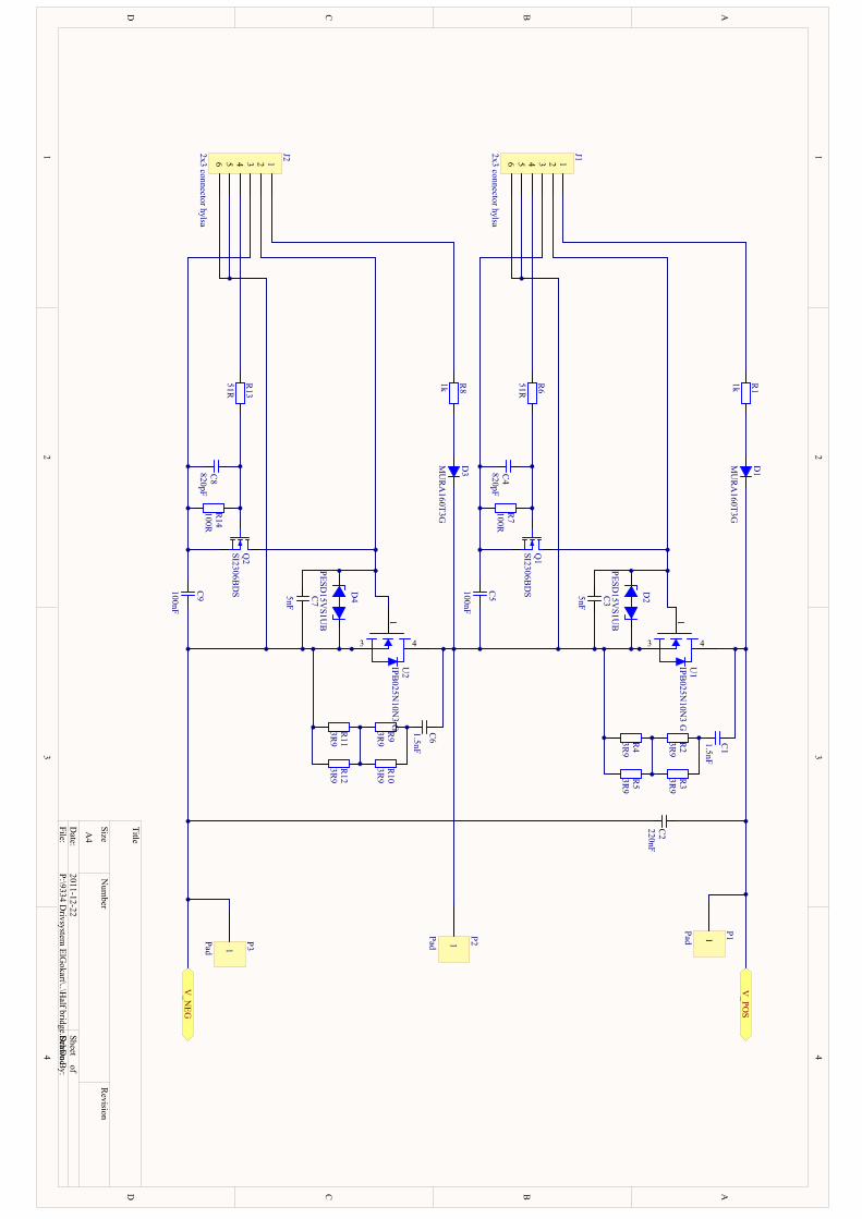
1 1
2 2
3 3
4 4
DD
CC
BB
AA
Title
Num
berR
evisionSize
A4
Date:
2011-12-22Sheet of
File:P:\9334 D
rivsystem ElG
okart\..\Half bridge.SchD
ocD
rawn By:
C2
220nFD
2
PESD15V
S1UB
R6
51RR
7100R
V_PO
S
C1
1.5nF
C4
820pF
R1
1k
D1
MU
RA160T3G
Q1
SI2306BD
S C3
5nF
C5
100nF
D4
PESD15V
S1UB
R13
51RR
14100R
V_N
EG
C6
1.5nF
C8
820pF
R8
1k
D3
MU
RA160T3G
Q2
SI2306BD
S C7
5nF
C9
100nF
1
P2Pad
1
P1Pad
3 12456
J12x3 connector hylsa
3 12456
J22x3 connector hylsa
R2
3R9
R3
3R9
R4
3R9
R5
3R9
R11
3R9
R9
3R9
R10
3R9
R12
3R9
1
43
U1
IPB025N
10N3 G
1
43
U2
IPB025N
10N3 G
1
P3Pad
PIC101 PIC102 COC1
PIC201 PIC202COC2
PIC301PIC302 C
OC3
PIC401 PIC402COC4
PIC501PIC502 C
OC5
PIC601 PIC602 COC6
PIC701PIC702 C
OC7
PIC801 PIC802COC8
PIC901PIC902 C
OC9
PID101PID102
COD1
PID201
PID202
COD2
PID301PID302
COD3
PID401
PID402
COD4
PIJ101
PIJ102
PIJ103
PIJ104
PIJ105
PIJ106
COJ1
PIJ201
PIJ202
PIJ203
PIJ204
PIJ205
PIJ206
COJ2
PIP101 COP1
PIP201 COP2
PIP301 COP3
PIQ101
PIQ102 PIQ103COQ1
PIQ201
PIQ202 PIQ203COQ2
PIR101PIR102
COR1
PIR201 PIR202COR2PIR301 PIR302COR3
PIR401 PIR402COR4PIR501 PIR502COR5
PIR601PIR602 C
OR6
PIR701PIR702 COR7
PIR801PIR802
COR8
PIR901 PIR902COR9PIR1001 PIR1002COR10
PIR1101 PIR1102COR11
PIR1201 PIR1202COR12
PIR1301PIR1302 C
OR13
PIR1401PIR1402 COR14
PIU101
PIU102PIU103 PIU104PIU105PIU106PIU107
COU1
PIU201
PIU202PIU203 PIU204PIU205PIU206PIU207
COU2
PIC101PIR202PIR302
PIC102
PIC202
PID102
PIP101
PIU104
POV0POS
PIC201
PIC701
PIC901 PID402
PIJ205
PIJ206
PIP301
PIR1101PIR1201
PIU202PIU203PIU205PIU206PIU207
POV0NEG
PIC301
PIC501
PIC602
PID202
PID302
PIJ105
PIJ106
PIP201
PIR401PIR501
PIU102PIU103PIU105PIU106PIU107PIU204
PIC302
PID201
PIJ102
PIQ103
PIU101
PIC401PIC502
PIJ103
PIQ102
PIR702
PIC402PIQ101
PIR601
PIR701
PIC601PIR902PIR1002
PIC702
PID401
PIJ202
PIQ203
PIU201
PIC801PIC902
PIJ203
PIQ202
PIR1402
PIC802
PIQ201PIR1301
PIR1401
PID101PIR102
PID301PIR802
PIJ101
PIR101
PIJ104
PIR602
PIJ201
PIR801
PIJ204
PIR1302
PIR201PIR301
PIR402PIR502
PIR901PIR1001
PIR1102PIR1202
POV0NEG
POV0POS
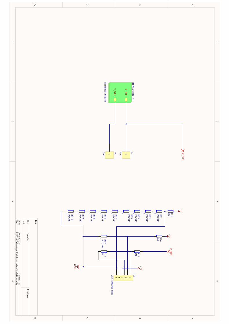
1 1
2 2
3 3
4 4
DD
CC
BB
AA
Title
Num
berR
evisionSize
A4
Date:
2011-12-22Sheet of
File:P:\9334 D
rivsystem ElG
okart\..\Main.SchD
ocDrawn By:
V_PO
S
V_N
EG
REPEA
T(HB
,1,9)
Half bridge.SchD
oc
t° RT7
NTC
10k
R17
87k
V_PO
S
3V3
R16
4k7
GN
D
R18
3k
V_PO
S
1
P4Pad1
P5Pad
3V3
R15
42k
t° RT2
PTC4k7
3V3t° R
T3PTC
4k7
t° RT4
PTC4k7
t° RT5
PTC4k7
t° RT1
PTC4k7
t° RT6
PTC4k7
3 12456
J32x3 connector hylsa
t° RT8
PTC4k7
t° RT9
PTC4k7
t° RT10
PTC4k7
PIJ301
PIJ302
PIJ303
PIJ304
PIJ305
PIJ306 COJ3
PIP401 COP4
PIP501 COP5
PIR1501 PIR1502COR15
PIR1601 PIR1602COR16
PIR1701 PIR1702COR17
PIR1801 PIR1802COR18
PIRT101PIRT102
CORT1
PIRT201PIRT202
CORT2
PIRT301PIRT302
CORT3
PIRT401PIRT402
CORT4
PIRT501PIRT502
CORT5
PIRT601PIRT602
CORT6PIRT701PIRT702
CORT7
PIRT801PIRT802
CORT8
PIRT901PIRT902
CORT9
PIRT1001PIRT1002
CORT10
PIJ304
PIR1502
PIR1602
PIJ305
PIRT702
PIRT1002
PIJ301
PIR1701PIR1802
PIJ302
PIR1601PIRT701
PIJ303
PIR1801
PIJ306
PIR1501PIRT101
PIP501
PIRT102PIRT201PIRT202PIRT301PIRT302PIRT401PIRT402PIRT501PIRT502PIRT601PIRT602PIRT801PIRT802PIRT901PIRT902PIRT1001
PIP401
PIR1702
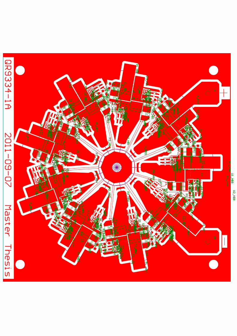
PAC10HB102
PAC10HB101
COC10HB1
PAC10HB202PAC10HB201
COC10HB2
PAC10HB302PAC10HB301
COC10HB3
PAC10HB402 PAC10HB401COC10HB4
PAC10HB502 PAC10HB501
COC10HB5
PAC10HB602
PAC10HB601
COC10HB6
PAC10HB702PAC10HB701
COC10HB7
PAC10HB802PAC10HB801
COC10HB8
PAC10HB902PAC10HB901
COC10HB9
PAC20HB101
PAC20HB102
COC20HB1
PAC20HB201PAC20HB202
COC20HB2
PAC20HB301PAC20HB302COC20HB3
PAC20HB401 PAC20HB402COC20HB4
PAC20HB501PAC20HB502
COC20HB5
PAC20HB601
PAC20HB602COC20HB6
PAC20HB701PAC20HB702COC20HB7
PAC20HB802PAC20HB801
COC20HB8
PAC20HB901PAC20HB902
COC20HB9
PAC30HB101PAC30HB102
COC30HB1
PAC30HB201PAC30HB202
COC30HB2
PAC30HB301PAC30HB302
COC30HB3
PAC30HB401PAC30HB402
COC30HB4
PAC30HB501PAC30HB502
COC30HB5
PAC30HB601
PAC30HB602
COC30HB6
PAC30HB701PAC30HB702
COC30HB7
PAC30HB802PAC30HB801
COC30HB8
PAC30HB901 PAC30HB902
COC30HB9
PAC40HB101PAC40HB102
COC40HB1
PAC40HB201 PAC40HB202
COC40HB2
PAC40HB301PAC40HB302
COC40HB3PAC40HB401
PAC40HB402
COC40HB4
PAC40HB501PAC40HB502
COC40HB5
PAC40HB601PAC40HB602
COC40HB6
PAC40HB701PAC40HB702
COC40HB7
PAC40HB802
PAC40HB801
COC40HB8
PAC40HB901PAC40HB902
COC40HB9
PAC50HB101PAC50HB102
COC50HB1
PAC50HB201 PAC50HB202
COC50HB2
PAC50HB301PAC50HB302
COC50HB3PAC50HB401
PAC50HB402
COC50HB4
PAC50HB501PAC50HB502
COC50HB5
PAC50HB601PAC50HB602
COC50HB6
PAC50HB701PAC50HB702
COC50HB7
PAC50HB802
PAC50HB801
COC50HB8
PAC50HB901PAC50HB902
COC50HB9
PAC60HB102
PAC60HB101
COC60HB1
PAC60HB202PAC60HB201
COC60HB2
PAC60HB302PAC60HB301
COC60HB3
PAC60HB402PAC60HB401
COC60HB4
PAC60HB502PAC60HB501
COC60HB5
PAC60HB602
PAC60HB601
COC60HB6
PAC60HB702PAC60HB701
COC60HB7
PAC60HB802PAC60HB801
COC60HB8
PAC60HB902 PAC60HB901
COC60HB9
PAC70HB101PAC70HB102
COC70HB1
PAC70HB201PAC70HB202
COC70HB2
PAC70HB301PAC70HB302
COC70HB3
PAC70HB401 PAC70HB402
COC70HB4
PAC70HB501PAC70HB502
COC70HB5
PAC70HB601PAC70HB602
COC70HB6
PAC70HB701PAC70HB702COC70HB7
PAC70HB802PAC70HB801
COC70HB8
PAC70HB901PAC70HB902
COC70HB9
PAC80HB101
PAC80HB102
COC80HB1
PAC80HB201PAC80HB202
COC80HB2
PAC80HB301PAC80HB302
COC80HB3
PAC80HB401PAC80HB402
COC80HB4
PAC80HB501PAC80HB502
COC80HB5
PAC80HB601
PAC80HB602
COC80HB6
PAC80HB701PAC80HB702
COC80HB7
PAC80HB802PAC80HB801
COC80HB8
PAC80HB901 PAC80HB902
COC80HB9
PAC90HB101
PAC90HB102
COC90HB1
PAC90HB201PAC90HB202
COC90HB2
PAC90HB301PAC90HB302
COC90HB3
PAC90HB401PAC90HB402
COC90HB4
PAC90HB501PAC90HB502
COC90HB5
PAC90HB601PAC90HB602
COC90HB6
PAC90HB701PAC90HB702
COC90HB7
PAC90HB802PAC90HB801
COC90HB8
PAC90HB901 PAC90HB902
COC90HB9
PAD10HB102PAD10HB101
COD10HB1
PAD10HB202 PAD10HB201COD10HB2
PAD10HB302 PAD10HB301COD10HB3
PAD10HB402PAD10HB401COD10HB4
PAD10HB502PAD10HB501COD10HB5
PAD10HB602PAD10HB601
COD10HB6
PAD10HB702PAD10HB701
COD10HB7PAD10HB801
PAD10HB802
COD10HB8
PAD10HB902PAD10HB901
COD10HB9
PAD20HB102PAD20HB101
COD20HB1
PAD20HB202 PAD20HB201
COD20HB2
PAD20HB302PAD20HB301
COD20HB3PAD20HB402
PAD20HB401
COD20HB4
PAD20HB502PAD20HB501
COD20HB5
PAD20HB602PAD20HB601
COD20HB6
PAD20HB702PAD20HB701
COD20HB7
PAD20HB801PAD20HB802
COD20HB8
PAD20HB902PAD20HB901
COD20HB9
PAD30HB102
PAD30HB101COD30HB1
PAD30HB202PAD30HB201COD30HB2
PAD30HB302PAD30HB301COD30HB3
PAD30HB402PAD30HB401
COD30HB4
PAD30HB502PAD30HB501
COD30HB5
PAD30HB602
PAD30HB601
COD30HB6
PAD30HB702PAD30HB701
COD30HB7
PAD30HB801PAD30HB802
COD30HB8
PAD30HB902 PAD30HB901COD30HB9
PAD40HB102PAD40HB101
COD40HB1
PAD40HB202PAD40HB201
COD40HB2
PAD40HB302PAD40HB301
COD40HB3
PAD40HB402PAD40HB401
COD40HB4
PAD40HB502PAD40HB501
COD40HB5
PAD40HB602 PAD40HB601
COD40HB6
PAD40HB702 PAD40HB701
COD40HB7
PAD40HB801PAD40HB802
COD40HB8
PAD40HB902PAD40HB901
COD40HB9
PAJ10HB104
PAJ10HB102PAJ10HB103
PAJ10HB101
PAJ10HB105PAJ10HB106
COJ10HB1PAJ10HB204PAJ10HB202 PAJ10HB203
PAJ10HB201
PAJ10HB205PAJ10HB206
COJ10HB2
PAJ10HB304PAJ10HB302
PAJ10HB303PAJ10HB301PAJ10HB305
PAJ10HB306
COJ10HB3
PAJ10HB404 PAJ10HB402PAJ10HB403 PAJ10HB401
PAJ10HB405PAJ10HB406
COJ10HB4
PAJ10HB504PAJ10HB502
PAJ10HB503PAJ10HB501
PAJ10HB505PAJ10HB506
COJ10HB5 PAJ10HB604
PAJ10HB602
PAJ10HB603
PAJ10HB601
PAJ10HB605PAJ10HB606
COJ10HB6
PAJ10HB704PAJ10HB702
PAJ10HB703PAJ10HB701PAJ10HB705 PAJ10HB706
COJ10HB7PAJ10HB806PAJ10HB805
PAJ10HB801PAJ10HB803PAJ10HB802PAJ10HB804COJ10HB8
PAJ10HB904PAJ10HB902
PAJ10HB903PAJ10HB901 PAJ10HB905
PAJ10HB906COJ10HB9
PAJ20HB104PAJ20HB102
PAJ20HB103PAJ20HB101PAJ20HB105
PAJ20HB106 COJ20HB1
PAJ20HB204 PAJ20HB202PAJ20HB203 PAJ20HB201
PAJ20HB205PAJ20HB206
COJ20HB2
PAJ20HB304PAJ20HB302
PAJ20HB303PAJ20HB301
PAJ20HB305PAJ20HB306
COJ20HB3
PAJ20HB404PAJ20HB402
PAJ20HB403PAJ20HB401
PAJ20HB405 PAJ20HB406
COJ20HB4
PAJ20HB504PAJ20HB502
PAJ20HB503PAJ20HB501PAJ20HB505 PAJ20HB506
COJ20HB5
PAJ20HB604PAJ20HB602PAJ20HB603
PAJ20HB601PAJ20HB605
PAJ20HB606COJ20HB6
PAJ20HB704PAJ20HB702
PAJ20HB703PAJ20HB701 PAJ20HB705
PAJ20HB706COJ20HB7
PAJ20HB806PAJ20HB805
PAJ20HB801
PAJ20HB803
PAJ20HB802
PAJ20HB804
COJ20HB8
PAJ20HB904PAJ20HB902 PAJ20HB903PAJ20HB901
PAJ20HB905PAJ20HB906
COJ20HB9
PAJ306 PAJ305PAJ301PAJ303
PAJ302PAJ304
COJ3
PAP10HB101COP10HB1PAP10HB201
COP10HB2
PAP10HB301COP10HB3
PAP10HB401COP10HB4
PAP10HB501COP10HB5 PAP10HB601
COP10HB6
PAP10HB701COP10HB7
PAP10HB801
COP10HB8
PAP10HB901COP10HB9
PAP20HB101COP20HB1
PAP20HB201COP20HB2
PAP20HB301COP20HB3
PAP20HB401COP20HB4
PAP20HB501COP20HB5
PAP20HB601COP20HB6
PAP20HB701COP20HB7
PAP20HB801 COP20HB8
PAP20HB901COP20HB9
PAP30HB101COP30HB1
PAP30HB201COP30HB2
PAP30HB301COP30HB3
PAP30HB401COP30HB4
PAP30HB501COP30HB5
PAP30HB601COP30HB6
PAP30HB701COP30HB7
PAP30HB801 COP30HB8
PAP30HB901COP30HB9
PAP402PAP401
PAP403PAP404
PAP405
PAP406
PAP407PAP408
PAP409PAP4010
PAP4011
PAP4012
COP4
PAP502PAP501
PAP503PAP504
PAP505
PAP506
PAP507PAP508
PAP509PAP5010
PAP5011
PAP5012
COP5
PAQ10HB101PAQ10HB102PAQ10HB103
COQ10HB1
PAQ10HB201PAQ10HB202PAQ10HB203
COQ10HB2
PAQ10HB301
PAQ10HB302 PAQ10HB303
COQ10HB3PAQ10HB401
PAQ10HB402 PAQ10HB403
COQ10HB4
PAQ10HB501PAQ10HB502
PAQ10HB503
COQ10HB5
PAQ10HB601PAQ10HB602
PAQ10HB603
COQ10HB6
PAQ10HB701 PAQ10HB702PAQ10HB703
COQ10HB7PAQ10HB803
PAQ10HB802
PAQ10HB801
COQ10HB8
PAQ10HB901PAQ10HB902
PAQ10HB903
COQ10HB9
PAQ20HB101
PAQ20HB102 PAQ20HB103
COQ20HB1
PAQ20HB201PAQ20HB202 PAQ20HB203
COQ20HB2
PAQ20HB301PAQ20HB302
PAQ20HB303
COQ20HB3
PAQ20HB401 PAQ20HB402PAQ20HB403
COQ20HB4
PAQ20HB501 PAQ20HB502PAQ20HB503
COQ20HB5
PAQ20HB601
PAQ20HB602
PAQ20HB603
COQ20HB6
PAQ20HB701PAQ20HB702
PAQ20HB703
COQ20HB7
PAQ20HB803PAQ20HB802
PAQ20HB801
COQ20HB8
PAQ20HB901PAQ20HB902PAQ20HB903
COQ20HB9
PAR10HB101
PAR10HB102
COR10HB1
PAR10HB201PAR10HB202
COR10HB2
PAR10HB301PAR10HB302
COR10HB3
PAR10HB401 PAR10HB402
COR10HB4
PAR10HB501 PAR10HB502
COR10HB5
PAR10HB601
PAR10HB602
COR10HB6
PAR10HB701PAR10HB702
COR10HB7PAR10HB802
PAR10HB801
COR10HB8
PAR10HB901PAR10HB902
COR10HB9
PAR20HB101PAR20HB102COR20HB1
PAR20HB201PAR20HB202
COR20HB2
PAR20HB301
PAR20HB302
COR20HB3
PAR20HB401
PAR20HB402
COR20HB4
PAR20HB501PAR20HB502
COR20HB5
PAR20HB601PAR20HB602
COR20HB6
PAR20HB701 PAR20HB702COR20HB7
PAR20HB801
PAR20HB802COR20HB8
PAR20HB901PAR20HB902COR20HB9
PAR30HB101PAR30HB102COR30HB1
PAR30HB201PAR30HB202
COR30HB2
PAR30HB301
PAR30HB302
COR30HB3
PAR30HB401
PAR30HB402
COR30HB4
PAR30HB501PAR30HB502
COR30HB5
PAR30HB601PAR30HB602
COR30HB6
PAR30HB701 PAR30HB702COR30HB7
PAR30HB801
PAR30HB802COR30HB8
PAR30HB901PAR30HB902COR30HB9
PAR40HB101PAR40HB102COR40HB1
PAR40HB201PAR40HB202
COR40HB2
PAR40HB301
PAR40HB302
COR40HB3
PAR40HB401PAR40HB402
COR40HB4
PAR40HB501PAR40HB502
COR40HB5
PAR40HB601PAR40HB602
COR40HB6
PAR40HB701 PAR40HB702COR40HB7
PAR40HB801
PAR40HB802COR40HB8
PAR40HB901PAR40HB902COR40HB9
PAR50HB101PAR50HB102COR50HB1
PAR50HB201PAR50HB202
COR50HB2
PAR50HB301
PAR50HB302
COR50HB3
PAR50HB401PAR50HB402
COR50HB4
PAR50HB501PAR50HB502
COR50HB5
PAR50HB601PAR50HB602
COR50HB6
PAR50HB701 PAR50HB702COR50HB7
PAR50HB801
PAR50HB802COR50HB8
PAR50HB901PAR50HB902COR50HB9
PAR60HB101
PAR60HB102
COR60HB1
PAR60HB201PAR60HB202
COR60HB2
PAR60HB301PAR60HB302
COR60HB3
PAR60HB401 PAR60HB402
COR60HB4
PAR60HB501 PAR60HB502
COR60HB5
PAR60HB601
PAR60HB602
COR60HB6
PAR60HB701PAR60HB702
COR60HB7
PAR60HB802PAR60HB801
COR60HB8
PAR60HB901PAR60HB902
COR60HB9
PAR70HB101PAR70HB102
COR70HB1
PAR70HB201PAR70HB202
COR70HB2
PAR70HB301PAR70HB302
COR70HB3
PAR70HB401
PAR70HB402
COR70HB4
PAR70HB501PAR70HB502
COR70HB5
PAR70HB601 PAR70HB602
COR70HB6
PAR70HB701 PAR70HB702
COR70HB7
PAR70HB802
PAR70HB801
COR70HB8
PAR70HB901PAR70HB902
COR70HB9PAR80HB101PAR80HB102
COR80HB1
PAR80HB201 PAR80HB202
COR80HB2
PAR80HB301
PAR80HB302
COR80HB3
PAR80HB401PAR80HB402
COR80HB4
PAR80HB501PAR80HB502
COR80HB5
PAR80HB601PAR80HB602
COR80HB6
PAR80HB701PAR80HB702
COR80HB7
PAR80HB802
PAR80HB801
COR80HB8
PAR80HB901PAR80HB902
COR80HB9
PAR90HB101PAR90HB102
COR90HB1
PAR90HB201 PAR90HB202COR90HB2
PAR90HB301 PAR90HB302COR90HB3
PAR90HB401
PAR90HB402COR90HB4
PAR90HB501PAR90HB502COR90HB5
PAR90HB601PAR90HB602COR90HB6
PAR90HB701PAR90HB702
COR90HB7
PAR90HB801
PAR90HB802
COR90HB8
PAR90HB901PAR90HB902
COR90HB9
PAR100HB101PAR100HB102
COR100HB1
PAR100HB201 PAR100HB202COR100HB2
PAR100HB301
PAR100HB302COR100HB3
PAR100HB401
PAR100HB402COR100HB4
PAR100HB501PAR100HB502COR100HB5
PAR100HB601PAR100HB602COR100HB6
PAR100HB701PAR100HB702
COR100HB7
PAR100HB801
PAR100HB802
COR100HB8
PAR100HB901PAR100HB902
COR100HB9
PAR110HB101PAR110HB102
COR110HB1
PAR110HB201 PAR110HB202COR110HB2
PAR110HB301 PAR110HB302COR110HB3
PAR110HB401
PAR110HB402COR110HB4
PAR110HB501PAR110HB502COR110HB5
PAR110HB601PAR110HB602COR110HB6
PAR110HB701PAR110HB702
COR110HB7
PAR110HB801
PAR110HB802
COR110HB8
PAR110HB901PAR110HB902
COR110HB9
PAR120HB101PAR120HB102
COR120HB1
PAR120HB201 PAR120HB202COR120HB2
PAR120HB301 PAR120HB302COR120HB3
PAR120HB401
PAR120HB402COR120HB4
PAR120HB501PAR120HB502COR120HB5
PAR120HB601PAR120HB602COR120HB6
PAR120HB701PAR120HB702
COR120HB7
PAR120HB801
PAR120HB802
COR120HB8
PAR120HB901PAR120HB902
COR120HB9
PAR130HB101PAR130HB102
COR130HB1
PAR130HB201PAR130HB202
COR130HB2
PAR130HB301PAR130HB302
COR130HB3
PAR130HB401
PAR130HB402
COR130HB4
PAR130HB501PAR130HB502
COR130HB5
PAR130HB601 PAR130HB602
COR130HB6
PAR130HB701 PAR130HB702
COR130HB7
PAR130HB802
PAR130HB801
COR130HB8
PAR130HB901PAR130HB902
COR130HB9
PAR140HB101
PAR140HB102
COR140HB1
PAR140HB201PAR140HB202
COR140HB2
PAR140HB301PAR140HB302
COR140HB3
PAR140HB401 PAR140HB402
COR140HB4
PAR140HB501PAR140HB502
COR140HB5
PAR140HB601
PAR140HB602
COR140HB6
PAR140HB701PAR140HB702
COR140HB7
PAR140HB802PAR140HB801
COR140HB8
PAR140HB901PAR140HB902
COR140HB9
PAR1502PAR1501
COR15
PAR1602PAR1601
COR16
PAR1702PAR1701
COR17
PAR1802PAR1801
COR18
PART102PART101
CORT1
PART202
PART201
CORT2
PART302 PART301
CORT3
PART402 PART401
CORT4
PART502PART501
CORT5
PART602PART601
CORT6
PART702PART701
CORT7
PART802
PART801
CORT8
PART902PART901
CORT9PART1002
PART1001
CORT10
PAU10HB104PAU10HB107PAU10HB106PAU10HB105
PAU10HB103PAU10HB102PAU10HB101
COU10HB1PAU10HB204 PAU10HB207PAU10HB206PAU10HB205
PAU10HB203PAU10HB202PAU10HB201
COU10HB2
PAU10HB304PAU10HB307PAU10HB306PAU10HB305PAU10HB303PAU10HB302PAU10HB301
COU10HB3
PAU10HB404PAU10HB407 PAU10HB406 PAU10HB405 PAU10HB403 PAU10HB402 PAU10HB401COU10HB4
PAU10HB504PAU10HB507PAU10HB506PAU10HB505
PAU10HB503PAU10HB502PAU10HB501
COU10HB5 PAU10HB604PAU10HB607PAU10HB606PAU10HB605
PAU10HB603PAU10HB602PAU10HB601
COU10HB6
PAU10HB704PAU10HB707
PAU10HB706PAU10HB705
PAU10HB703PAU10HB702
PAU10HB701
COU10HB7PAU10HB804PAU10HB807PAU10HB806
PAU10HB805PAU10HB803PAU10HB802
PAU10HB801
COU10HB8
PAU10HB904PAU10HB907PAU10HB906
PAU10HB905PAU10HB903
PAU10HB902PAU10HB901
COU10HB9
PAU20HB104PAU20HB107PAU20HB106PAU20HB105
PAU20HB103PAU20HB102PAU20HB101
COU20HB1PAU20HB204PAU20HB207
PAU20HB206PAU20HB205
PAU20HB203PAU20HB202
PAU20HB201
COU20HB2
PAU20HB304PAU20HB307PAU20HB306
PAU20HB305PAU20HB303
PAU20HB302PAU20HB301 COU20HB3
PAU20HB404PAU20HB407PAU20HB406
PAU20HB405PAU20HB403
PAU20HB402PAU20HB401
COU20HB4
PAU20HB504PAU20HB507
PAU20HB506PAU20HB505
PAU20HB503PAU20HB502
PAU20HB501
COU20HB5 PAU20HB604PAU20HB607PAU20HB606PAU20HB605
PAU20HB603PAU20HB602PAU20HB601
COU20HB6
PAU20HB704 PAU20HB707PAU20HB706PAU20HB705PAU20HB703
PAU20HB702PAU20HB701
COU20HB7
PAU20HB801PAU20HB802PAU20HB803
PAU20HB805PAU20HB806PAU20HB807PAU20HB804
COU20HB8
PAU20HB904PAU20HB907
PAU20HB906PAU20HB905 PAU20HB903
PAU20HB902PAU20HB901
COU20HB9
PAJ304PAR1502PAR1602 PAJ305
PART702 PART1002
PAC10HB101PAR20HB102 PAR30HB102
PAC10HB201PAR20HB202PAR30HB202
PAC10HB301PAR20HB302
PAR30HB302
PAC10HB401 PAR20HB402PAR30HB402
PAC10HB501
PAR20HB502PAR30HB502 PAC10HB601
PAR20HB602PAR30HB602
PAC10HB701PAR20HB702PAR30HB702
PAC10HB801
PAR20HB802PAR30HB802
PAC10HB901
PAR20HB902 PAR30HB902
PAC20HB101PAC20HB201
PAC20HB301PAC20HB401
PAC20HB501
PAC20HB601
PAC20HB701
PAC20HB801
PAC20HB901
PAC70HB101
PAC70HB201
PAC70HB301
PAC70HB401
PAC70HB501
PAC70HB601
PAC70HB701
PAC70HB801
PAC70HB901
PAC90HB101PAC90HB201
PAC90HB301
PAC90HB401
PAC90HB501
PAC90HB601
PAC90HB701
PAC90HB801
PAC90HB901
PAD40HB102
PAD40HB202
PAD40HB302
PAD40HB402
PAD40HB502
PAD40HB602
PAD40HB702
PAD40HB802
PAD40HB902
PAJ20HB105
PAJ20HB106
PAJ20HB205PAJ20HB206
PAJ20HB305PAJ20HB306
PAJ20HB405 PAJ20HB406
PAJ20HB505 PAJ20HB506
PAJ20HB605PAJ20HB606
PAJ20HB705PAJ20HB706
PAJ20HB805PAJ20HB806
PAJ20HB905PAJ20HB906
PAP30HB101PAP30HB201
PAP30HB301PAP30HB401
PAP30HB501
PAP30HB601
PAP30HB701
PAP30HB801
PAP30HB901
PAP501
PAR110HB101
PAR110HB201
PAR110HB301
PAR110HB401
PAR110HB501
PAR110HB601
PAR110HB701
PAR110HB801PAR110HB901
PAR120HB101
PAR120HB201
PAR120HB301
PAR120HB401
PAR120HB501
PAR120HB601
PAR120HB701
PAR120HB801
PAR120HB901
PAU20HB102PAU20HB103
PAU20HB105PAU20HB106PAU20HB107
PAU20HB202PAU20HB203
PAU20HB205PAU20HB206PAU20HB207
PAU20HB302PAU20HB303PAU20HB305PAU20HB306PAU20HB307PAU20HB402 PAU20HB403 PAU20HB405 PAU20HB406 PAU20HB407
PAU20HB502PAU20HB503
PAU20HB505PAU20HB506PAU20HB507
PAU20HB602PAU20HB603
PAU20HB605PAU20HB606PAU20HB607
PAU20HB702PAU20HB703
PAU20HB705PAU20HB706
PAU20HB707
PAU20HB802PAU20HB803PAU20HB805PAU20HB806
PAU20HB807
PAU20HB902PAU20HB903
PAU20HB905PAU20HB906
PAU20HB907
PAC30HB101
PAC50HB101
PAC60HB102
PAD20HB102
PAD30HB102
PAJ10HB105PAJ10HB106
PAP20HB101PAR40HB101 PAR50HB101 PAU10HB102
PAU10HB103
PAU10HB105PAU10HB106PAU10HB107
PAU20HB104PAC30HB102
PAD20HB101PAJ10HB102
PAQ10HB103PAU10HB101
PAC30HB201
PAC50HB201
PAC60HB202PAD20HB202
PAD30HB202
PAJ10HB205PAJ10HB206
PAP20HB201
PAR40HB201PAR50HB201
PAU10HB202PAU10HB203
PAU10HB205PAU10HB206
PAU10HB207PAU20HB204
PAC30HB202PAD20HB201
PAJ10HB202PAQ10HB203
PAU10HB201
PAC30HB301
PAC50HB301
PAC60HB302
PAD20HB302PAD30HB302
PAJ10HB305PAJ10HB306 PAP20HB301PAR40HB301
PAR50HB301
PAU10HB302PAU10HB303
PAU10HB305PAU10HB306
PAU10HB307PAU20HB304
PAC30HB302PAD20HB301
PAJ10HB302PAQ10HB303
PAU10HB301
PAC30HB401PAC50HB401
PAC60HB402PAD20HB402
PAD30HB402
PAJ10HB405PAJ10HB406
PAP20HB401
PAR40HB401PAR50HB401
PAU10HB402PAU10HB403
PAU10HB405PAU10HB406
PAU10HB407PAU20HB404
PAC30HB402PAD20HB401
PAJ10HB402PAQ10HB403
PAU10HB401
PAC30HB501
PAC50HB501
PAC60HB502
PAD20HB502
PAD30HB502
PAJ10HB505PAJ10HB506
PAP20HB501PAR40HB501
PAR50HB501PAU10HB502
PAU10HB503PAU10HB505
PAU10HB506PAU10HB507
PAU20HB504PAC30HB502
PAD20HB501
PAJ10HB502PAQ10HB503PAU10HB501 PAC30HB601
PAC50HB601
PAC60HB602
PAD20HB602
PAD30HB602
PAJ10HB605PAJ10HB606
PAP20HB601
PAR40HB601PAR50HB601PAU10HB602PAU10HB603
PAU10HB605PAU10HB606PAU10HB607
PAU20HB604
PAC30HB602PAD20HB601
PAJ10HB602
PAQ10HB603PAU10HB601
PAC30HB701
PAC50HB701
PAC60HB702
PAD20HB702
PAD30HB702
PAJ10HB705 PAJ10HB706
PAP20HB701
PAR40HB701PAR50HB701PAU10HB702PAU10HB703PAU10HB705
PAU10HB706PAU10HB707PAU20HB704
PAC30HB702PAD20HB701
PAJ10HB702 PAQ10HB703 PAU10HB701
PAC30HB801
PAC50HB801
PAC60HB802
PAD20HB802
PAD30HB802
PAJ10HB805 PAJ10HB806PAP20HB801
PAR40HB801PAR50HB801
PAU10HB802PAU10HB803PAU10HB805PAU10HB806PAU10HB807 PAU20HB804PAC30HB802PAD20HB801PAJ10HB802
PAQ10HB803 PAU10HB801
PAC30HB901
PAC50HB901
PAC60HB902
PAD20HB902
PAD30HB902
PAJ10HB905PAJ10HB906
PAP20HB901
PAR40HB901 PAR50HB901PAU10HB902PAU10HB903 PAU10HB905
PAU10HB906PAU10HB907PAU20HB904
PAC30HB902 PAD20HB901
PAJ10HB902PAQ10HB903
PAU10HB901
PAC40HB101PAC50HB102
PAJ10HB103PAQ10HB102 PAR70HB102 PAC40HB102
PAQ10HB101 PAR60HB101
PAR70HB101
PAC40HB201PAC50HB202
PAJ10HB203
PAQ10HB202PAR70HB202 PAC40HB202PAQ10HB201
PAR60HB201PAR70HB201
PAC40HB301PAC50HB302
PAJ10HB303
PAQ10HB302PAR70HB302
PAC40HB302PAQ10HB301
PAR60HB301PAR70HB301PAC40HB401PAC50HB402
PAJ10HB403
PAQ10HB402PAR70HB402
PAC40HB402PAQ10HB401
PAR60HB401PAR70HB401
PAC40HB501PAC50HB502
PAJ10HB503PAQ10HB502
PAR70HB502PAC40HB502 PAQ10HB501
PAR60HB501 PAR70HB501
PAC40HB601 PAC50HB602
PAJ10HB603
PAQ10HB602PAR70HB602
PAC40HB602
PAQ10HB601
PAR60HB601 PAR70HB601
PAC40HB701 PAC50HB702
PAJ10HB703
PAQ10HB702PAR70HB702
PAC40HB702PAQ10HB701PAR60HB701
PAR70HB701
PAC40HB801PAC50HB802
PAJ10HB803
PAQ10HB802 PAR70HB802PAC40HB802PAQ10HB801
PAR60HB801PAR70HB801
PAC40HB901PAC50HB902
PAJ10HB903
PAQ10HB902 PAR70HB902PAC40HB902PAQ10HB901
PAR60HB901PAR70HB901
PAC60HB101
PAR90HB102PAR100HB102
PAC60HB201PAR90HB202PAR100HB202
PAC60HB301PAR90HB302PAR100HB302
PAC60HB401
PAR90HB402 PAR100HB402
PAC60HB501
PAR90HB502 PAR100HB502
PAC60HB601PAR90HB602PAR100HB602
PAC60HB701PAR90HB702
PAR100HB702
PAC60HB801PAR90HB802
PAR100HB802
PAC60HB901
PAR90HB902PAR100HB902
PAC70HB102PAD40HB101
PAJ20HB102PAQ20HB103
PAU20HB101
PAC70HB202PAD40HB201
PAJ20HB202PAQ20HB203
PAU20HB201
PAC70HB302PAD40HB301PAJ20HB302
PAQ20HB303PAU20HB301PAC70HB402 PAD40HB401
PAJ20HB402PAQ20HB403 PAU20HB401
PAC70HB502 PAD40HB501
PAJ20HB502 PAQ20HB503
PAU20HB501
PAC70HB602PAD40HB601
PAJ20HB602
PAQ20HB603
PAU20HB601
PAC70HB702PAD40HB701
PAJ20HB702PAQ20HB703
PAU20HB701
PAC70HB802PAD40HB801
PAJ20HB802PAQ20HB803
PAU20HB801
PAC70HB902PAD40HB901 PAJ20HB902
PAQ20HB903
PAU20HB901
PAC80HB101PAC90HB102 PAJ20HB103
PAQ20HB102
PAR140HB102
PAC80HB102PAQ20HB101
PAR130HB101PAR140HB101
PAC80HB201PAC90HB202
PAJ20HB203
PAQ20HB202PAR140HB202
PAC80HB202 PAQ20HB201PAR130HB201PAR140HB201
PAC80HB301 PAC90HB302
PAJ20HB303PAQ20HB302PAR140HB302
PAC80HB302
PAQ20HB301PAR130HB301PAR140HB301
PAC80HB401
PAC90HB402
PAJ20HB403
PAQ20HB402PAR140HB402PAC80HB402
PAQ20HB401PAR130HB401 PAR140HB401
PAC80HB501PAC90HB502
PAJ20HB503
PAQ20HB502 PAR140HB502PAC80HB502
PAQ20HB501PAR130HB501 PAR140HB501
PAC80HB601PAC90HB602PAJ20HB603
PAQ20HB602 PAR140HB602PAC80HB602
PAQ20HB601 PAR130HB601PAR140HB601
PAC80HB701PAC90HB702
PAJ20HB703
PAQ20HB702PAR140HB702
PAC80HB702
PAQ20HB701 PAR130HB701PAR140HB701
PAC80HB801
PAC90HB802PAJ20HB803
PAQ20HB802PAR140HB802 PAC80HB802
PAQ20HB801PAR130HB801
PAR140HB801
PAC80HB901PAC90HB902
PAJ20HB903
PAQ20HB902PAR140HB902
PAC80HB902PAQ20HB901
PAR130HB901PAR140HB901
PAD10HB101PAR10HB102
PAD10HB201
PAR10HB202
PAD10HB301 PAR10HB302PAD10HB401
PAR10HB402
PAD10HB501PAR10HB502
PAD10HB601
PAR10HB602
PAD10HB701
PAR10HB702
PAD10HB801
PAR10HB802
PAD10HB901
PAR10HB902PAD30HB101 PAR80HB102
PAD30HB201PAR80HB202
PAD30HB301PAR80HB302
PAD30HB401PAR80HB402
PAD30HB501PAR80HB502
PAD30HB601PAR80HB602
PAD30HB701PAR80HB702
PAD30HB801PAR80HB802
PAD30HB901 PAR80HB902
PAJ10HB101
PAR10HB101
PAJ10HB104PAR60HB102
PAJ10HB201
PAR10HB201 PAJ10HB204PAR60HB202
PAJ10HB301PAR10HB301
PAJ10HB304PAR60HB302
PAJ10HB401
PAR10HB401
PAJ10HB404PAR60HB402
PAJ10HB501PAR10HB501
PAJ10HB504PAR60HB502
PAJ10HB601
PAR10HB601
PAJ10HB604 PAR60HB602
PAJ10HB701
PAR10HB701
PAJ10HB704 PAR60HB702PAJ10HB801
PAR10HB801
PAJ10HB804PAR60HB802
PAJ10HB901
PAR10HB901PAJ10HB904
PAR60HB902PAJ20HB101
PAR80HB101
PAJ20HB104PAR130HB102
PAJ20HB201 PAR80HB201
PAJ20HB204PAR130HB202
PAJ20HB301PAR80HB301
PAJ20HB304PAR130HB302
PAJ20HB401PAR80HB401
PAJ20HB404PAR130HB402
PAJ20HB501PAR80HB501
PAJ20HB504PAR130HB502
PAJ20HB601PAR80HB601 PAJ20HB604 PAR130HB602
PAJ20HB701PAR80HB701
PAJ20HB704PAR130HB702
PAJ20HB801PAR80HB801
PAJ20HB804PAR130HB802
PAJ20HB901PAR80HB901PAJ20HB904
PAR130HB902
PAJ301 PAR1701PAR1802
PAJ302PAR1601
PART701PAJ303
PAR1801
PAJ306PAR1501
PART101
PAR20HB101 PAR30HB101PAR40HB102 PAR50HB102
PAR20HB201PAR30HB201PAR40HB202
PAR50HB202
PAR20HB301PAR30HB301 PAR40HB302PAR50HB302
PAR20HB401PAR30HB401 PAR40HB402
PAR50HB402
PAR20HB501PAR30HB501PAR40HB502
PAR50HB502 PAR20HB601PAR30HB601PAR40HB602PAR50HB602
PAR20HB701PAR30HB701PAR40HB702PAR50HB702
PAR20HB801PAR30HB801
PAR40HB802PAR50HB802
PAR20HB901 PAR30HB901PAR40HB902 PAR50HB902
PAR90HB101PAR100HB101
PAR110HB102PAR120HB102
PAR90HB201PAR100HB201PAR110HB202PAR120HB202
PAR90HB301PAR100HB301PAR110HB302PAR120HB302
PAR90HB401 PAR100HB401PAR110HB402 PAR120HB402
PAR90HB501 PAR100HB501PAR110HB502 PAR120HB502
PAR90HB601PAR100HB601PAR110HB602
PAR120HB602
PAR90HB701PAR100HB701PAR110HB702
PAR120HB702
PAR90HB801PAR100HB801 PAR110HB802PAR120HB802
PAR90HB901PAR100HB901
PAR110HB902PAR120HB902
PART102
PART201PART202
PART301PART302
PART401PART402
PART501PART502
PART601PART602
PART801
PART802
PART901 PART902PART1001
PAC10HB102
PAC10HB202
PAC10HB302
PAC10HB402
PAC10HB502 PAC10HB602
PAC10HB702
PAC10HB802
PAC10HB902
PAC20HB102
PAC20HB202
PAC20HB302PAC20HB402
PAC20HB502
PAC20HB602
PAC20HB702
PAC20HB802
PAC20HB902
PAD10HB102
PAD10HB202
PAD10HB302
PAD10HB402
PAD10HB502
PAD10HB602
PAD10HB702
PAD10HB802
PAD10HB902
PAP10HB101
PAP10HB201
PAP10HB301PAP10HB401
PAP10HB501 PAP10HB601
PAP10HB701
PAP10HB801
PAP10HB901
PAP401
PAR1702
PAU10HB104PAU10HB204
PAU10HB304PAU10HB404
PAU10HB504 PAU10HB604
PAU10HB704PAU10HB804
PAU10HB904