a combination conformal-transfinite mapping method for grids about fin-afterbody combinations
TRANSCRIPT

A Combination Conforma�-Transfinite Mapping Methodfor Grids about Fin-Afterbody Combinations
Gi�bert H. Hoffman
App�ied Research LaboratoryThe Pennsy�vania State UniversityPost Office Box 30State Co��ege, Pennsy�vania 16804
Transmitted by Joe Thompson
ABSTRACT
An a�gebraic procedure is presented for the generation of a smooth computationa�grid about an afterbody-fin configuration. The method makes use of a sequence ofconforma� transformations to unwrap the geometry and remove the comer singu�ari-ties at the fin trai�ing edge and tai� of the afterbody . A 3-D grid is generated bystacking a sequence of 2-D grids of the C type on predetermined, smooth tubu�arsurfaces. C�ustering is accomp�ished by a sequence of one-dimensiona� stretchingfunctions in physica� space. Examp�es are presented to show the character of theresu�ting grid.
I . INTRODUCTION
The prob�em treated in this paper is the generation of a surface-fitted gridin the stem region of an undersea vehic�e, specifica��y an axisymmetricpointed afterbody with four identica�, symmetric, constant chord fins . Inmany respects this prob�em is simi�ar to the airp�ane wing-fuse�age prob�em .The desired grid is to be used for either inviscid or viscid incompressib�e-f�ow ca�cu�ations and hence must have proper c�ustering abi�ity to reso�veregions of high f�ow gradients. An a�gebraic approach is used which is an
* This research was sponsored joint�y by the Office of Nava� Research and Nava� Sea SystemsCommand.
APPLIED MATHEMATICS AND COMPUTATION 22 :309-331
309E�sevier Science Pub�ishing Co., Inc., 1987
52 Vanderbi�t Ave., New York, NY 10017
009&3003/87/$03 . .50

310
GILSERT H. HOFFMAN
outgrowth of ear�ier 3-D grid generation work on a fin-cy�inder configuration[1]
A�gebraic grid generation methods for three-dimensiona� (3-D) f�ow prob-�ems have the advantage over their differentia�-equation counterparts inspeed and abi�ity to hand�e high-aspect-ratio ce��s without difficu�ty . Wherethe a�gebraic methods are sometimes at a disadvantage is in treating a widevariety of boundary shapes with a sing�e code .
Since 1979 grids about wing-body configurations have been successfu��ygenerated by severa� a�gebraic approaches . Eriksson [2] has generated asing�e-b�ock nonorthogona� 3-D grid using transfinite interpo�ation wheregeometric data are specified on�y on the boundaries . Since no interna�surfaces are specified, grid qua�ity is contro��ed, especia��y near a surface, byincorporating out-of-surface parametric derivatives . Smith et a�. [3] simp�ifythe generation of a 3-D grid by using the bui�ding-b�ock concept wheresevera� adjoining or partia��y over�apping physica� grids map to a computa-tiona� cube . On the interior of each bui�ding b�ock transfinite interpo�ation isused to generate the grid . Their treatment extends on�y to the wing tips,which �imits its usefu�ness . A third and quite different approach has beentaken by Caughey and Jameson [4] . Their technique generates a boundary-conforming coordinate system by a sequence of conforma� and shearingtransformations to yie�d a near�y orthogona� computationa� domain. The gridis then generated by simp�e �inear interpo�ation . Shmi�ovich and Caughey [5]have recent�y extended this technique to inc�ude a tai� surface . TheCaughey-Jameson procedure was deve�oped for use with the :3-D transonicFLO codes .
One of the major difficu�ties in a�gebraic grid generation is preventingcorner singu�arities on the boundaries from propagating into the grid . Anyinterpo�ation method wi�� propagate such singu�arities into the interior .Differentia� equation grid generation schemes suffer no such prob�em becauseof the diffusive action of the e��iptic operator . Comer singu�arities are a�wayspresent in 3-D configurations at wing/fin trai�ing edges and tai� points onpointed bodies . A method for removing these singu�arities in a�gebraic gridgeneration has been deve�oped by Vinokur and Lombard [6] for 2-D geome-tries . Their method consists of patching a conforma� hinge-point transforma-tion in a sma�� region near the corner to a grid in the remainder of thedomain generated by transfinite interpo�ation. They successfu��y app�ied thismethod in generating a patched grid in a domain consisting of a backward-facing step at the end of a nozz�e exhausting into a cy�indrica� diffuser.
The a�gebraic method adopted here was origina��y inspired by the work ofCaughey and Jameson in unwrapping a geometry as much as possib�e toproduce a para��e�piped with near�y straight boundaries . This procedure is ofthe stacking type where a 3-D grid is produced by a sequence of 2-D grid

Mapping about Fin and Afterbody
311
generation operations . In the present method stacked tubu�ar surfaces ofcircu�ar cross-section are first determined and then a C-type grid generatedon each surface. In the process of generating these surfaces as we�� as inunwrapping the airfoi�, comer singu�arities are removed by app�ication of ahinge point transformation to the entire boundary . The present approachthus differs from that of Vinokur and Lombard in being g�oba� rather than�oca� in the use of the hinge-point transformation . The resu�t is a smoothboundary with a s�ow�y varying tangent . A grid which is orthogona� at a��boundaries is then generated on the interior by transfinite interpo�ation . Byusing a sequence of one-dimensiona� stretching functions in physica� space,precise contro� is maintained over the c�ustering at a�� boundaries .
II . ANALYSIS
Geometry of Computationa� DomainWe start by defining the geometry for which a surface-fitted grid is to be
generated .
(1) The afterbody is of circu�ar cross-section and has a smooth butotherwise arbitrary meridian profi�e that c�oses at the tai� point .
(2) Four identica� fins of constant unit chord and infinite span, consistingof symmetric airfoi� sections, are mounted 90 degrees apart with their chord
Ftc . 1 . Schematic of geometry and computationa� domain .

312
GILRERT H. HOFFMAN
Y
FIG. 2. P�anes of symmetryy
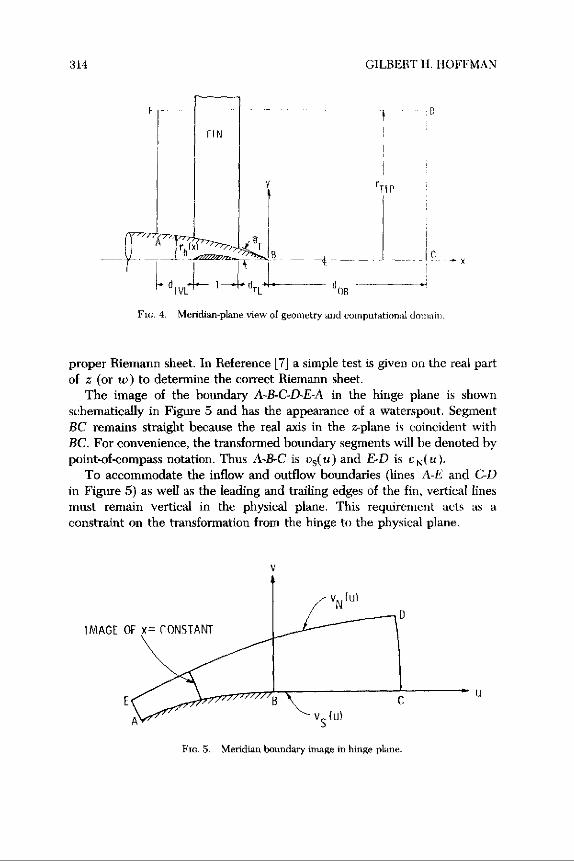
p�anes passing through the afterbody center�ine . The trai�ing edges of the finsare �ocated upstream of the tai� point a distance dr ,, .
(3) The computationa� domain consists of the region interior to an outercy�inder of radius rr1 , and exterior to the afterbody, bounded upstream anddownstream by p�anes norma� to the afterbody center�ine (the initia� va�ueand outf�ow p�anes) .
A schematic of the geometry and computationa� domain is shown inFigure 1, and a head-on view showing the coordinate system in the crossf�owp�ane appears in Figure 2. Since the fins are identica� and equa��y spaced,there are four p�anes of symmetry at B = 0, a/4, 27/2, and 327/4 . Thus, on�ythe section - 27/4 B 0 is considered in generating a grid and in thef�owfie�d ca�cu�ation .
Grid Stacking ProcedureThe simp�est grid stacking scheme, such as that in Reference [4], makes
use of a shearing transformation to distribute a sequence of two-dimensiona��yproduced grids in the third spatia� direction . Unfortunate�y the shearingtransformation causes surface corner discontinuities to propagate into thegrid. In the present case of a pointed tai� body, Figure 3 i��ustrates thesituation that wou�d exist in the meridian p�ane if a shearing transformationwere used . A�ong the vertica� �ine through the tai� point, x = xr , �ines ofconstant rt have discontinuous s�opes .
UPPER SYMMETRY PLANE,0= ,r14
LOWER SYMMETRY PLANE,
B=-n14

Mapping about Fin and Afferbody
313
Fic . 3 . Grid in meridian p�ane using shearing transformation .
What is needed is a transformation to produce r� = constant �ines that doesnot propagate corner discontinuities. The hinge-point (power-�aw) conforma�transformation has this desired property . At the tai� point (comer discontinu-ity) we write
The tai� ang�e Br is defined in the meridian-p�ane schematic given in Figure4. Equation (1) maps the sector 0 c B c - Br above the rea� axis onto theupper ha�f p�ane. If Equation (1) is app�ied to the entire bounding curve inthe meridian p�ane, A-B-GD-&A, the corner at the tai� point B is e�iminatedin the w (hinge) p�ane. Then interpo�ating a grid in the hinge p�ane, upontransformation, wi�� produce a smooth grid (except at B) in the physica�p�ane, which can be used for stacking .
The on�y difficu�ty in determining w (given z), or vice versa, arises fromthe exponent n not being an integer, so that one must be carefu� to se�ect the
w=zm, (1)
where the rea� axis is a�igned with the axis of symmetry, and
z = x + iy, (2)
w=u+iv, (3)
aJ1= (4)
m-8,
314
CILBEBT H . HOFFMAN
F
FIN
rh _�7~(eo,r~r __ ~T
~'d IVL'
� ' tdTL �
F OR
Fir. . 4 . Meridian-p�ane view of geometry and computationa� domain .
proper Rfemann sheet . In Reference [7] a simp�e test is given on the rea� partof z (or w) to determine the correct Riemann sheet .
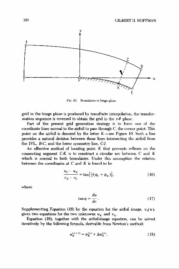
The image of the boundary A-B-C-D-E-A in the hinge p�ane is shownschematica��y in Figure 5 and has the appearance of a waterspout . SegmentBC remains straight because the rea� axis in the z-p�ane is coincident withBC. For convenience, the transformed boundary segments wi�� be denoted bypoint-of-compass notation . Thus A-B-C is o 5(u) and £4) is r N( u)
To accommodate the inf�ow and outf�ow boundaries (�ines A-B and C-I.)in Figure 5) as we�� as the �eading and trai�ing edges of the fin, vertica� �inesmust remain vertica� in the physica� p�ane . This requirement acts as aconstraint on the transformation from the hinge to the physica� p�ane .
U
Fm . 5. Meridian boundary image in hinge p�ane_

Mapping about Fin and Afterbody
315
The simp�est scheme for producing a grid in the hinge p�ane is a shearingtransformation on the image of x = constant �ines . For this purpose, anorma�ized variab�e r is defined as
v-vsUN-US
x-cons[
Vu= vsa + r�(vN - vs )„
BF=sin-'Iys I,
(5)
At this point the distribution of F7 is assumed known, and hence in theinterior v is given by
(B)
where the index i is constant on x=constant �ines . Thus at point (i, j) theva�ues of x ; and v, are known. Then (y, u)11 are determined by iterative�yso�ving Equation (1).
Using the above procedure, a smooth curve y5(x) is determined in themeridian p�ane for each va�ue of F=constant . By revo�ving y5(x) about thex-axis a tubu�ar coordinate surface is obtained which is smooth and nondeve�-opab�e (except when it is a cy�inder) . On each of these surfaces a surface-fittedgrid is determined as though the surface were deve�opab�e, then projectedback onto the surface . This means that given (x, B), r is determined byinterpo�ation of the tubu�ar meridian-p�ane curve rs(x)=y5(x) . For theprojection method to work proper�y, the foi� subtended ang�e BF ( x) must becomputed to account for the variab�e r5(r) from
(7)
where YF(x) is the airfoi� semithickness distribution . Cubic interpo�ation ofthe Lagrange type [8] is used to determine r, given x, from the previous�ydetermined va�ues of rs .
An a�ternative to the hinge-point transformation as a means of e�iminatingthe corner at the tai� point is the Karman-Trefftz (K-T) transformation . TheK-T transformation, being �oca� in character, has the advantage of distortingthe boundary significant�y on�y in the vicinity of the corner, the distortion ofthe other boundaries being s�ight. On the other hand, the K-T transformationis more comp�icated than a pure hinge-point transformation and hence ismore difficu�t to app�y in the sense of Equation (5).
C�ustering of F = constant �ines near the body surface is needed to reso�vethe viscous �ayer, whereas further away, where f�ow gradients diminish, these

316
CILBEBT H . HOFFMAN
�ines can be further apart . A one-sided stretching function is thereforeappropriate to determine the grid �ine spacing in the meridian p�ane .
Vinokur [9] has determined approximate criteria for the deve�opment ofone- and two-sided stretching functions of one variab�e which give a uniformtruncation error independent of the governing differentia� equation or dif-ference a�gorithm . He investigates severa� ana�ytic functions but finds thaton�y tan z, where z is rea� or pure imaginary, satisfies a�� of his criteria . Thesestretching functions were used in the predecessor grid generation scheme [1]and are a�so used here .
Since i is a�ready a norma�ized variab�e, its distribution is given by
=ftanh[z0¢(g-�)]
(8)T
�tank = 9¢
where is the norma�ized generating variab�e given by
- j-1
A4 is the so�ution of
sink 14Sn = 1¢
(q)
and
Su =
Nr = ( number of interva�s in i) =
- 1 .
Grid Generation on a Tubu�ar SurfaceGrid generation in the x-6 p�ane is accomp�ished in three stages . The first
stage invo�ves a sequence of conforma transformations to unwrap the airfoi�,symmetry �ines, and initia� and outf�ow �ines into a quadri�atera� with a s�ow�yvarying height. The unwrapping transformations are the basis for producing aC-grid about the airfoi� . The second stage invo�ves trans�ation and rotation ofcoordinates about the image of the airfoi� trai�ing edge, fo��owed by a

Mapping about Fin and AJterbodg
317
hinge-point transformation to e�iminate the corner at the trai�ing edge . Thethird stage makes use of transfinite interpo�ation to determine the grid in thehinge p�ane that is orthogona� at a�� boundaries . Since the boundaries in thehinge p�ane are smooth and have a s�ow�y varying tangent, transfiniteinterpo�ation wi�� produce a smooth grid in which nonorthogona�ity in theinterior is he�d to a minimum . The grid in the physica� p�ane is obtained bytaking the inverse of the sequence of transformations . Since the intermediatetransformations are conforma�, the orthogona�ity at boundaries and gridsmoothness wi�� be preserved in the physica� p�ane . The spacing of grid �inesis determined on appropriate boundaries in the physica� p�ane by use ofstretching functions .
Once the coordinates of the fin airfoi� (x,,, 04 are specified on anr = constant tubu�ar surface, the first step, in preparation for the unwrappingtransformation, is to sca�e the (x, B) coordinates according to
z = 4(x - d s)+1n2,(10)
B = 40,
where ds is the �ocation of the singu�ar point in the unwrapping transforma-tion and is just inside the �eading edge of the airfoi� . The stretching factor 4 isrequired by the unwrapping transformation so that the upper �imit on B wi��be t ar (the upper and �ower symmetry p�anes are at B ± rr/4) .
In References [1] and [4], x is trans�ated but not magnified, whereas 0 ismagnified as above. Unequa� sca�ing is of course not conforma�, so thatorthogona�ity of the grid cannot be maintained at the boundaries . Theresu�ting grid in the x-0 p�ane wi�� be high�y f�attened and thus high�ynonorthogona� .
On an r = constant surface the boundaries and coordinate system in thex-0 p�ane are sketched in Figure 6 . Because of symmetry, on�y the region- ar 0 6 0 needs to be considered. The airfoi� can be unwrapped byapp�ying the conforma� transformation
x+iB=�n[1-cosh(+iij)] .
(11)
Equation (11) maps the region be�ow the x-axis to positive in the bando ,� a. Figure 7 presents a schematic of the boundaries in the #-q p�ane .The initia� va�ue �ine (IVL) A-B-C is seen to map into a near-semicirc�e .
Fo��owing Reference [1], the comers at points A and C can be e�iminatedby app�ying the conforma� transformation
2
#+i~=i+in+ +°i~,
(12)

318
C;ILBERT H. HOFFMAN
INITIAL
i,._- •VALUE LINE
UPPER SYMMETRY PLANE
LOWER SYMMETRY PLANE
Fin . 6. Computationa� domatn .
constant surface
where o is defined in Figure 7 . Equation (12) has the effect of near�ystraightening out the IVL . The geometry of the boundaries in the -ij p�ane isshown in Figure 8 .
In Reference [1] a shearing transformation is used to generate a grid in theE-U p�ane. For airfoi�s with nonzero trai�ing-edge ang�es this procedureproduces discontinuous metric coefficients across the �ine E- EF . To e�iminatethe effect of the corner at the trai�ing edge (point F) a procedure simi�ar tothe generation of the smooth curves in the meridian p�ane is used . The (E, ij)coordinates are first trans�ated and rotated about point F according to
x=(EP - f�cosai. +(n p -~) sinA F ,(13)
y=-( F -UsinA F_ +( f -~)cosX f ,
where the positive z-axis points toward point E, the airfoi� �eading edge, and
AF is the trai�ing-edge ang�e in the :-7f p�ane. The trans�ated and rotated -jboundaries are sketched in Figure 9 .
UPPER SYM . LINE -Eb \ .Eb LOWER SYM . LINE
UPSTREAM "
Ftc . 7 . - Boundaries in E-f� p�ane .

Mapping about Fin and A,fterbodg
319
FIG . 8 . Boundaries in positive !•-8 p�ane.
The fina� step in producing a smooth boundary is to app�y a hinge-pointtransformation to (1, 9) to e�iminate the corner at point F . Equation (1)app�ies provided z = i t 19 and
ITn=
IT AX,
(14)
where
The resu�ting boundary in the hinge p�ane is sketched in Figure 10. Once a
FIG . 9 . Trans�ated and rotated boundaries in 1-y p�ane .
3 20
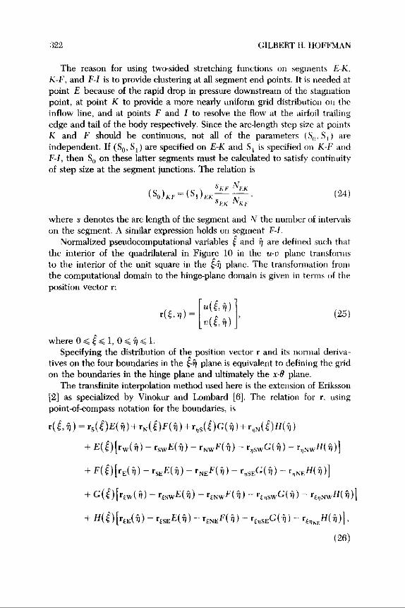
Pie . 10 . Boundaries in hinge p�ane .
grid in the hinge p�ane is produced by transfinite interpo�ation, the transfor-mation sequence is reversed to obtain the grid in the x-D p�ane .
Part of the present grid generation strategy is to force one of thecoordinate �ines norma� to the airfoi� to pass through C, the corner point . Thispoint on the airfoi� is denoted by the �etter K-see Figure 10. Such a �ineprovides a natura� division between those �ines intersecting the airfoi� fromthe IVL, B-C, and the �ower symmetry �ine, C-I.
An effective method of �ocating point K that prevents ref�exes on theconnecting segment C-K is to construct a circu�ar arc between C and Kwhich is norma� to both boundaries . Under this assumption the re�ationbetween the coordinates at C and K is found to be
u .-uRvK-vc
-ta~i~a($c+$K)] .
(16)
where
dutan $ = r�v .
(17)
Supp�ementing Equation (16) by the equation for the airfoi� image, us( ii),gives two equations for the two unknowns uh and vx .
Equation (16), together with the airfoi�-image equation, can be so�vediterative�y by the fo��owing formu�a, derivab�e from Newton's method :
uk i = uK + Dud
(18)
GILBERT H. HOFFMAN

Mapping about Fin and Afterbody
321
here
uC - uK+(VC - VK)tan`2($C+*K)] (n,AnK
1+tan~Ktan[E($C+4r.K)]
19
The right-hand side of Eq . (19) is eva�uated from va�ues at point K at the nthiteration �eve�. In the determination of vK i and tangy", Lagrange cubicinterpo�ation is used. Convergence of u K is quite rapid, requiring usua��yabout four or five iterations to reach IAu K I c 10-0 . Once (u, v)K are known,(x, 9)K are found by the inverse transformation of the mapping sequence .
In the x-9 p�ane, the two-sided stretching function of Vinokur is used togenerate the grid-point distributions on the stagnation stream�ine B-E and theairfoi�-wake center�ine E-K-F I. For segment B-E a sing�e stretching functionis used, whereas for segment E-K-F-I a sequence of three stretching functionsis required .
The two-sided stretching function for the norma�ized variab�e t is given by
_
t (EA$) 20tAsinhA+(1-AcoshA)tanh(EA)'
()
where is the norma�ized generating variab�e of constant step size, A~ is theso�ution of the transcendenta� equation
sink $B =
A
(21)
and
A=(So/S )"2 ,
B = (SS)1/2 ,
in which S o and S 1 are dimension�ess s�opes defined as
So= dt (0),
Si
dt (1),
which contro� the c�ustering at t = 0 and t =1 .
(22)
(23)
322
GILBERT H. HOFFMAN
The reason for using two-sided stretching functions on segments E-K,K-F', and F-I is to provide c�ustering at a�� segment end points . It is needed atpoint E because of the rapid drop in pressure downstream of the stagnationpoint, at point K to provide a more near�y uniform grid distribution on theinf�ow �ine, and at points F and I to reso�ve the f�ow at the airfoi� trai�ingedge and tai� of the body respective�y. Since the arc-�ength step size at pointsK and F shou�d be continuous, not a�� of the parameters (S r„ S ) areindependent . If (So , S r ) are specified on E-K and S r is specified on K-F andF-I, then S„ on these �atter segments must be ca�cu�ated to satisfy continuityof step size at the segment junctions . The re�ation is
SKF 's'Ex( SO)KF - ( S I)Ef
_
( 2 `1 )Su< AFP
where s denotes the arc �ength of the segment and N the number of interva�son the segment . A simi�ar expression ho�ds on segment F-I .
Norma�ized pseudocomputationa� variab�es and are defined such thatthe interior of the quadri�atera� in Figure 10 in the u-u p�ane transformsto the interior of the unit square in the - i p�ane. The transformation fromthe computationa� domain to the hinge-p�ane domain is given in terns of theposition vector r :
r( �) [uftn)]
(2?)U(~~~)
where 0 c
1,0 7 51 .Specifying the distribution of the position vector r and its norma� deriva-
tives on the four boundaries in the -fj p�ane is equiva�ent to defining the gridon the boundaries in the hinge p�ane and u�timate�y the x-B p�ane .
The transffnite interpo�ation method used here is the extension of Eriksson[2] as specia�ized by Vinokur and Lombard [6] . The re�ation for r, usingpoint-of-compass notation for the boundaries, is
r(,~)=rs(E')E(n)+ N(€)F(fi)+r,1sOG(Ij)+rqN(€)H(n)
+E(')[rw(f�) - rswE(f�) - rNwF(T�) - r„swG(T�) - r„NwH(TI)1
+F( )[rE(f�) - r5NE( 7)) - rNEF(TI) - r„sEG(f�) - r„NEH(f1)I
+ G(t) [riw(f) - rtswE(T1) - rENWF(n) - rBnswG ('n) --
+
rt,,;vwH(f7 )~
H(s)[r(E(TI) - r$SEE(n) - rENEF(TI) - rt„SEG(TI) -r£,7 .`H(TI)~,
(26)

Mapping about Fin and Afterbody
s
4
2
V 1
a
I
2
7
2
•1 1U
Fic . 11. Typica� grid in hinge p�ane using transfinite interpo�ation .
where E, F, G and H are cubic b�ending functions given by
F(u)=u2(3-2u),
G(u) = u(1 - u)2 ,
H(u) =u 2(u-1),
E(u)=1-F(u) .
323
(27)
Equation (26) thus provides a smooth b�ending on the interior of the givendistribution of grid points and norma� derivatives on the boundaries . Atypica� grid in the hinge p�ane obtained by transfinite interpo�ation is shownin Figure 11 .
The eva�uation of the various derivatives on the boundaries in Eq. (26)fo��ows the prescription given by Vinokur and Lombard and is presented indetai� in Appendix II of Reference [7] .
The procedure described above produces a C-grid in the x-B p�ane in theregion upstream of the tai� �ine I-J. Because E=constant �ines in theupstream grid are norma� to I-J (and I-J is straight as we�� as norma� tothe wake center�ine), a downstream grid can easi�y be created which hascontinuity through first derivatives across I-J. The add-on grid which has

324
CILBERT H. HOFFMAN
these characteristics is a Cartesian grid with the same 0-distribution at 1-I asthe upstream grid . Distributing grid points on the xdirection downstream of1-I is accomp�ished by a one-sided Vinokur stretching function with theparameter S o determined by requiring continuity of Ax on either side of I-I .
Computationa� GridIf indices i, j, and k denote the coordinates E, ~, and r . then the
computationa� coordinates x, y, and z may be convenient�y defined as
The advantage of this system is that the computationa� step size in the threedirections is unity, which simp�ifies the metric-coefficient ca�cu�ations .
III. RESULTS AND DISCUSSION
The afterbody-fin grid generation code, ca��ed TAwcRtn, consists of about1800 FORTRAN statements and computes in terms of rea� variab�es on�y . Todate a�� grid generation has been done on a VAX 11/782 computer with CPUper grid point found to be about 7>< 10 sec. Thus computing a surfacecontaining 1500 points requires approximate�y 10 sec •. .
O .SOr
-] SO
-ICE
-0 .50
000
0 .54)
100
1.50k
Fir. 12 . Typica� 2-0 grid produced by present method .
SO
R=i-1,
i= ] 1,
1CiCi,ny ,
I c]
j„r . (28)

Mapping about Fin and Afterbody
325
The airfoi� fami�y chosen for testing the grid generation procedure was theNACA symmetric four-digit series . The equation for this profi�e is
ifF = - 5T(0.2969f -0.1281x-0.3516x 2 +0.2843x'-0.1015x'), (29)
where T is the maximum thickness expressed as a fraction of the chord . In theorigina� equation for yF (see Equation (6.2) of Reference [10]), the coefficientof x is given as 0 .12600, which causes the airfoi� to have a finite trai�ing-edgethickness (yTE = 0.0021). Since the grid generation procedure requires zerotrai�ing-edge thickness, the coefficient of x was modified as shown inEquation (29) . Interpo�ation is used �ibera��y on the airfoi� in the gridgeneration process; thus an accurate definition of yF versus x is a necessity .Usua��y 100 points on the airfoi� are computed for this purpose, withc�ustering at the �eading edge.
Figure 12 i��ustrates a typica� 2'D grid produced by this method beforeprojection onto a tubu�ar surface . In this examp�e, c�ustering is used at the foi��eading and trai�ing edges as we�� as at point K . The foi� section is an NACA0012. Further 2-D examp�es which i��ustrate the effects of various inputparameters may be found in Reference [7] . Figure 13 shows a 3-D schematicof how the boundaries appear after conforma� mapping .
INFLOW SURFACE
V
r
45 DEGREE SYMMETRY PLANE
U
Ftc. 13. Configuration of boundaries after conforma� mapping sequence .
STAGNATIONSTREAMSNRFACE

326
GILBERT H. HOFFMAN
For a 3-D test prob�em the afterbody meridian profi�e was represented bythe fo��owing ana�ytic function :
where
and F and G arc the cubic b�ending functions defined by Equation (27) . Theparticu�ar va�ues chosen for the afterbody parameters are
rat =0 .75,
d ba,=2 .5,
tanOT =0.50,
which produce a fair�y fu�� profi�e with a tai� ha�f ang�e of 26 .6 degrees .The meridian p�ane view of the test-prob�em geometry, computationa�
domain, and intermediate surface is shown in Figure 14 . Two views of eachT = constant surface are presented : the first from be�ow and in front, and thesecond from the side . These views are shown in Figures 15 through 20 . A
re,(µ)=ru,�F(µ)-d1 1 tanBTG(IL),
L
d i,od
1 IX)4 = afterbody �ength,
= initia� afterbody radius,
Fm. 14. Meridian-p�ane view of test-prob�em geometry .
(30)

Mapping about Fin and Afterbody
Ftc. 15. Front view of afterbody grid .
2
Ftc . 18 . Side view of afterbody grid.
Ftc . 17 . Front view of intermediate-surface grid .

328
Fir. . 18. Side view of intermediate-surface grid .
Fw. 19 . Front view of outer-surface grid .
composite side view showing the position of each surface re�ative to the otheris presented in Figure 21 . In this examp�e, the same type of c�ustering is usedas in Figure 12 .
In a grid-stacking procedure, each grid on a surface is generated somewhatindependent�y of the other . The dependence is indirect through the geome-try, and not direct as in the case of partia�-differentia�-equation grid genera-tion schemes or fu��y 3-D a�gebraic schemes . Thus for 3-D grids generated bystacking, one of the primary concerns is with smoothness in the stackingdirection. In the present method, the on�y reason that the grid changes in thex-8 p�ane from surface to surface is that the airfoi� image is changing . As rincreases, the airfoi� image, according to Equation (7), is shrinking in terms ofmaximum thickness approximate�y as 1/r5. A�though the tota� arc �ength ofthe airfoi� image is a�so shrinking s�ight�y as F increases, the c�usteringparameters are fixed and hence the airfoi� point distribution on each surfaceis a�ways in the same proportion. As the airfoi� image grows thinner, point Ks�ow�y moves toward the �eading edge . The trace of point K in the meridianp�ane is shown in Figure 13 . On the other hand, the distribution of points mrthe stagnation �ine remains the same, independent of r . Of course, c�ose tothe surface of the afterhody in the vicinity of the tai�, the grid shrinks rapid�yto ref�ect the pointed nature of the tai� and the axis singu�arity . This feature
GILRERT H. HOFFMAN

Mapping about Fin and Afterbody
329

Fm
. 21.
Comp
osit
e view of afterbody, intennediate•
siufaoe, and outer-ssufaee grids.

Mapping about Fin and Afterbody
331
wou�d exist whether or not stacking were used . Thus because the airfoi�image is varying s�owing as r increases and the points on the image remain inthe same proportion of arc �ength, the present method can be expected toproduce a grid of high qua�ity in the stacking direction .
One aspect of the current strategy of point p�acement on boundaries is notentire�y satisfactory. A�though the circu�ar-arc method of point p�acement inthe hinge p�ane works we�� on the �ower symmetry �ine, it �eaves something tobe desired on the IVL . Coup�ed with the singu�arity at the corner (point C)and the orthogona�ity requirement at boundaries, c�ustering at point K wasfound to be necessary to achieve a reasonab�e point spacing near point C onthe IVL. This c�ustering wou�d probab�y not be necessary if a differentstrategy were used to �ocate the points on the IVL . One possibi�ity wou�d beto space them in the x-8 p�ane in the same proportion of arc �ength as a�ongthe airfoi� between the �eading edge and point K. Downstream of point Kthe strategy wou�d remain as before.
REFERENCES
1 G. H. Hoffman, Grid Generation about a Fin-Cy�inder Combination, ARL/PSUTM 83115, App�ied Research Lab ., The Pennsy�vania State Univ ., UniversityPark, Pa., 30 Mar. 1983 .
2 L. E. Eriksson, Generation of boundary-conforming grids around wing-bodyconfigurations using transfinite interpo�ation, AIAA J . 20:1313-1320 (1982).
3 R. E. Smith, Jr., E . L. Everton, and R. A. Kud�inski, A�gebraic Grid Generationfor Wing-Fuse�age Bodies, AIAA Paper 84-0002, presented at AIAA 22ndAerospace Sci. Meeting, Reno, Nev., 9-12 Jan . 1984.
4 D. A. Caughey and A. Jameson, Numerica� ca�cu�ation of transonic potentia� f�owabout wing-body combinations, AL4A J . 17:175-181 (1979) .
5 A. Shmi�ovich and D . A . Caughey, Grid generation for wing-tai�-fuse�age config-urations, in Advances in Grid Generation, ASME FED, Vo�. 5, pp. 189-197 ;presented at App�. Mech ., Bioengrg . and F�uids Engrg. Conf., Houston, Tex .,20-22 June 1983 .
B M. Vinokur and C . K . Lombard, A�gebraic grid generation with corner singu�ari-ties, in Advances in Grid Generation, ASME FED, Vo� . 5, pp. 99-108; pre-sented at App�. Mech., Bicengrg. and F�uids Engrg. Conf., Houston, Tex., 20-22June 1983.
7 G. H. Hoffman, A�gebraic grid generation about a fin-afterbody configuration,ARL/PSU TM 8557, App�ied Research Lab ., The Pennsy�vania State Univ.,University Park, Pa ., 12 Apr . 1985 .
8 K. E. Atkinson, An Introduction to Numerica� Ana�ysis, Wi�ey, New York, 1978,p. 110 .
9 M. Vinokur, On one-dimensiona� stretching functions for finite-difference ca�cu�a-tions, NASA CR-3133, Oct. 1980.
10 Ira H. Abbott and A. E. Von Dcenhoff, Theory of Wing Sections, Dover, 1959,p. 113 .