a b cdefc cddcb f c cb f ˘ˇˇˆ - magneticservices.com.mt · electric motor efficiency motori 4...
TRANSCRIPT
������������������A�BCDEF�C��CDDCB���F����C��C�BF���������D�����B�C���F����E�CB���C��B��F�C� �!�������F�C�������������BC���EE��C�C"�FB�C�C��� �CBC�F�D�FE�C��""C�CBF��C���� F��C"��BF�F�BF����D#��������F��$������F�F����E��F��F��F�$CEE%�BF�F�F����E%F����CB����B� FBF�F�&��'�B�"�����#F$�E�D�����DEF�����C$��E�$$F�E�C�F��������E�B����DE��������C��#��C�C���BC� �CB�F��FC��!�B��D���C�F���� CB�""C�C�F�D�������C�C��F���$���D��BF��$F�EC���E�$F����������F����$������F�F����E��(F��E��D���F ���CBB����#F$�%C�DC����� �C�C BC�D���C�����E�C�F��C�D��$C�����BC�DF$��F���)�#CD�C�E��FB�F�C �C"�F�C��C�*�C���!��F�������������������B��C�C��C�����FDD��BC���!�F��C��DF�#�"����+�FD����F�%C��F�$FDD����C��C� C�F����������E�B��B��E�$$F�E�C����B�B��#��$F�EC��������F���E�B��B��F����F���#F�D���F�&$F��E%F���'&���EC�����F�������FB�F��C,,�CEE�CB���*��B�����������E�B��BFB���
&��� ����#F$������F�����B�B�$F�D��$C���F���E�B�DE������B����������$�B����FD����C����-./��F��C�������C�����"��BF��$CB�FBFB����BC� C$$C�������������FD��F$C$FB�F�#CD�C�F� C�CB�FB���D���"��B��F�D�BC��""C�F�C��F�C"�FB�F�E%F�%CBB��DEF��������C#��C�F�E�B�B����&���)����0.�CBB���C��C�BCDE��C�E�B��B��C$��C����F�C�F�E�B��C�D�FDDC��CDD��BF��E�B� ���D�FDD��#C������E�B��C�D�FDDC� ��B�C���CD$FDDC��C���B�C���F��DF$��F�$���#C���BF��C���EF�EC����D���"��B���BB�#C��#F��F�����FBF�F��C�D����D�C"��BF��F��B�D���E��FB���
���������������A�A�B�CDE�F�����������DEED���������D��D�������������F������ ���!�D����D��� �CDE�D���D�"�#����C�����F���� �D�E$D����D���!�DF#�F��$�E%���������#�����E�&� �D�����'����$��#��F����!#��!�$�#��E�D�� �&����D��" ���#D#��&����!#��!�$D!����E�� ��#���(�&�����&���'�$�!��E#�#�#��� #���!�$$��!�D� �(�D�!���F �����C�#� � #��������E�� #� �&�'��(��#� � #� �D�&��D# � ����E#��D� � ��D��#" ���&D��)���D���E#��!#�����#��(�!�$��D�$D��FD!#������F����!#��!�$�#��E�*����&�#���"�D�E���'�$�CDE�D(���#��&D���$����D���$����#���#��E#�D���#�����E��!#��F�D��D�&��!����!#��� �#�D�%E�#��#���+�D��#"��F��#E��C�������!#E ����#���#���#E����F�EE���D��E$�D���E��'�!������E��#���&E�D���C�� ���'�$�#��C������#E�!�$$��!�D��!��F���$��#E������C�$D�%�#E �(�"����#���������D��!��F���$��#E �#�CD��E �,$���!D �,F��!D �#�����������DE# ��$(�D!��&�#����F����D���#���!��#����#E�
���D"���'�$ �E#���&�����#E�C����C�����E#�$D#�����-���#E�./0��F�#�����#��# �$D��#D����&�D�'��"�C�����D�&���F������!#E�D���F����E���&�!�E#�$�E���E���#���E�#��#���F��$E�#�D#��D'��!��E���#��C��%�C�#���E��,F#���$��� �#�D��1/�"�D�E�F��$��#E�F����D#��� �C��%�����������D#��&�C�#��#���ED$���DEE��� �C�#��#���ED$��'D���E �C�#� �#���ED$��E����#�#�D�EF������("�#���F������ �E#�������%��&�F�������'D#�'��E���#���E�F���#���ED#�EFD!#�����F���� �!�E#�$��E�
(F��C�D�FD��C��F��EC�C�� ��1�D�C�C��F��EC�C��C�$CDD�$C�C��FB"��BF�C����BF����CDD�E��C�F��'CEE��C�F""C��F���C��� � ����C#�C�B�B�D����DD�B��CEEF��C�F��FD��BDC,����!��F��F#FB��C���F��������$�DD��B�����C���B�B�C ���BC����'��"�!D����DE�(����#D%������#�����DC��&�����F�#���!D#D��&�� �#����E����#���D!!��D!"��F�#�����F��$D#����!��#D��������#��E���(��!D#���2 ���C�'��������E���ED(���#"�!D��(��D!!��#���F���D�"������E ��$�EE���E������#����D#����D#D�
����������
3
INDICE / INDEX
1 - Caratteristiche generali / General speciications
2 - Norme speciiche di riferimento / Reference standards
3 - Rendimenti / Eficiency3.1 - Calcolo risparmio energetico / Energetic saving calculation
4 - Forme costruttive / Available conigurations
5 - Tolleranze / Tolerances5.1 - Tolleranze elettriche / Electric tolerances
5.2 - Tolleranze meccaniche / Mechanical tolerances
6 - Caratteristiche meccaniche / Mechanical speciications6.1 - Materiali / Materials
6.2 - Dimensioni principali di accoppiamento langia/albero / Main assembling dimension lange/shaft6.3 - Rumorosità / Sound levels
6.4 - Vibrazioni / Vibrations
6.5 - Verniciatura / Finishing coat
6.6 - Protezione contro la corrosione / Corrosion protection
6.7 - Grado di protezione IP / Housing protection level IP
7 - Caratteristiche elettriche / Electric speciications7.1 - Isolamento ed avvolgimento statorico / Insulation and stator winding
7.2 - Variazione potenza per condizioni ambientali / Variations of power related to environment7.3 - Alimentazione con inverter / Inverter control
7.4 - Variazione caratteristiche nominali / Variation of nominal speciications7.5 - Tipo di servizio / Type of duty7.6 - Frequenza massima di avviamento / Maximum starting frequency
8 - Cuscinetti / Bearings8.1 - Cuscinetti ed intervalli di lubriicazione / Bearing size and regreasing informations8.2 - Carichi radiali ed assiali / Radial and axial loads on shaft end
9 - Motori autofrenanti / Brake motors9.1 - Scelta del freno / Choice of the brake9.2 - Caratteristiche serie AT - AM / Characteristics of model AT - AM9.3 - Caratteristiche serie ATK - AMK / Characteristics of model ATK - AMK9.4 - Caratteristiche del freno serie AKTH / Characteristics of brake model AKTH9.5 - Caratteristiche del freno serie ATR / Characteristics of brake model ATR9.6 - Caratteristiche serie ATC / Characteristics of model ATC
10 - Prestazioni motori / Technical data
11 - Esecuzioni speciali / Special conigurations
12 - Dimensioni / Overall dimensions
13 - Parti di ricambio / Spare parts
14 - Appendice / Appendix14.1 - Schemi di collegamento / Connection diagrams
14.2 - Legenda / Legenda
14.3 - Condizioni generali di fornitura / Terms and conditions of sale
............ 4
............ 6
............ 7
............ 8
............ 8
............ 9
............ 9
............ 9
.......... 10
.......... 10
.......... 10.......... 11.......... 11.......... 12.......... 12.......... 13
.......... 14
.......... 14
.......... 15
.......... 15
.......... 16
.......... 17
.......... 19
.......... 20
.......... 21
.......... 22
.......... 23
.......... 23
.......... 25
.......... 28
.......... 31
.......... 32
.......... 34
.......... 37
.......... 47
.......... 53
.......... 59
.......... 61
.......... 61
.......... 62
.......... 63
4
1 - CARATTERISTICHE GENERALI
Questo catalogo contiene la descrizione e i dati tecnici principali dei motori elettrici asincroni trifase e monofase standardizzati in bassa tensione, con rotore a gabbia di scoiattolo, completamente chiusi, autoventilati (secondo IC 411), con o senza freno.La serie trifase comprende: 16 altezze d’asse (56...355) ad una velocità di rotazione (2, 4, 6 o 8 poli); 12 altezze (71...280) a due velocità (2/4, 4/8, 4/6 o 6/8 poli).La serie monofase comprende 7 altezze d’asse (56...112) ad una velocità di rotazione (2 o 4 poli).Le caratteristiche generali dei motori sono le seguenti:
tensione standard:•
alta qualità costruttiva• alto rendimento • さ ed alto fattore di potenza cosllivello della rumorosità molto al di sotto dei • valori deiniti dalle norme CEI EN 60034-9classe di isolamento F, con sovratemperature • classe Bsicurezza nel servizio• manutenzione sempliicata• elevata possibilità di personalizzazione•
motore trifase 63...180 singola o doppia • polarità con freno in corrente continua a basso ingombromotore trifase 63...225 singola o doppia • polarità con freno in corrente continua ad alta coppia di frenaturamotore monofase 63...100 singola polarità • con freno in corrente continua a basso ingombromotore monofase 63...100 singola polarità • con freno in corrente continua ad alta coppia di frenaturamotore trifase 63...200 singola o doppia • polarità con freno in corrente alternata ad alta coppia di frenatura
three-phase motor 63...180 single or • double speed, with small size DC brakethree-phase motor 63...225 single or • double speed, with high torque DC brakesingle-phase motor 63...100 single speed, • with small size DC brakesingle-phase motor 63...100 single speed, • with high torque DC brakethree-phase motor 63...200 single or • double speed, with high torque AC brake
standard voltage:•
high quality construction• high efficiency さ and power factor cosl• very low noisy, much below CEI EN 60034-9•
speciications class F insulation, class B overheating• safety in duty• simple maintenance• very customizable•
1 - GENERAL SPECIFICATIONS
This catalogue contains description and technical data of totally enclosed, three-phase and single-phase, squirrel cage, fan cooled (as IC 411) electric motors, with or without brake.Three-phase motor range includes: 16 shaft heights (56...355) single speed motors (2, 4, 6 or 8 poles); 12 shaft heights (71...280) double speed motors (2/4, 4/8, 4/6 or 6/8 poles).Single-phase motor range includes 7 shaft heights (56...112) single speed motors (2 or 4 poles).Here below the general speciications of the motors:
I motori asincroni trifase e monofase autofrenanti sono fornibili nelle seguenti conigurazioni:
Three-phase and single-phase brake motors can be supplied in following conigurations:
∆230V/Y400V ±10% 50Hz per i motori trifase56...100 a 2, 4, 6, 8 poli∆400V ±10% 50Hz per i motori trifase 100...355 a 2, 4, 6, 8 poli230V ±5% 50Hz per i motori monofase 2, 4 poli400V ±10% 50Hz per i motori doppia polarità 71...280
∆230V/Y400V ±10% 50Hz for three-phasemotors, size 56...100 at 2, 4, 6, 8 poles∆400V ±10% 50Hz for three-phase motors, size 100...355 at 2, 4, 6, 8 poles230V ±5% 50Hz for single-phase motors 2, 4 poles400V ±10% 50Hz for double speed motors, size 71...280
5
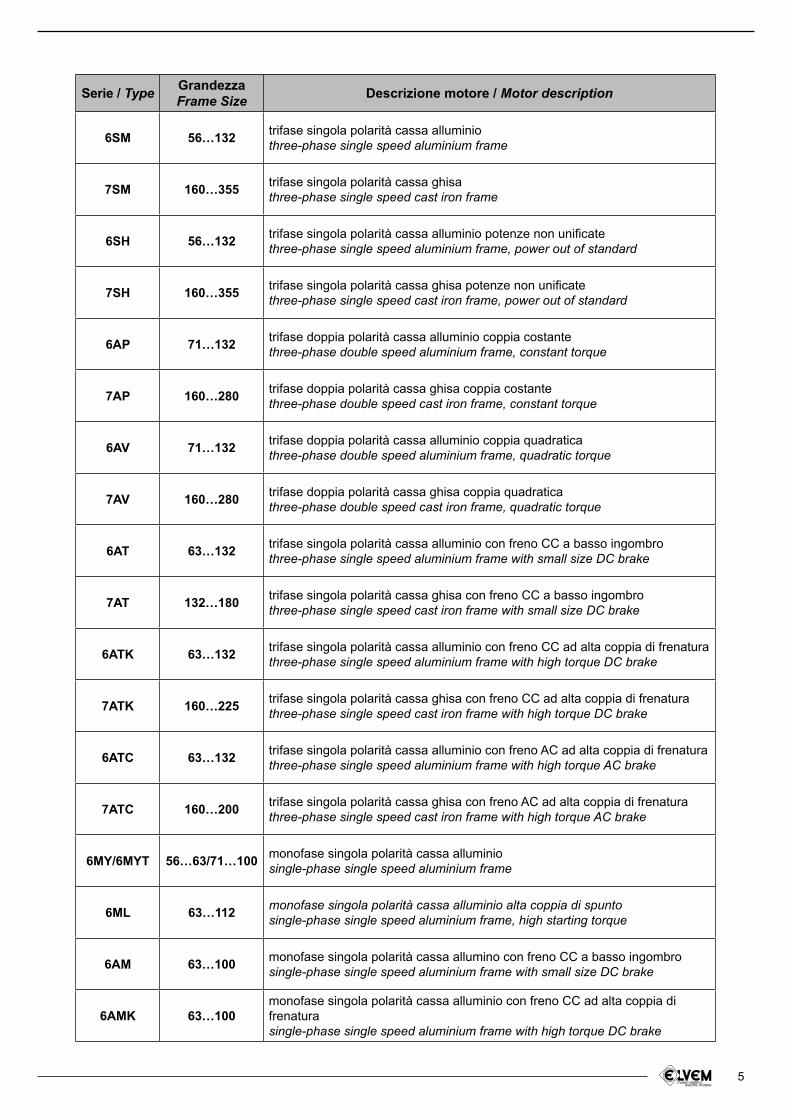
Serie / Type GrandezzaFrame Size Descrizione motore / Motor description
6SM 56…132trifase singola polarità cassa alluminiothree-phase single speed aluminium frame
7SM 160…355trifase singola polarità cassa ghisathree-phase single speed cast iron frame
6SH 56…132trifase singola polarità cassa alluminio potenze non uniicatethree-phase single speed aluminium frame, power out of standard
7SH 160…355trifase singola polarità cassa ghisa potenze non uniicatethree-phase single speed cast iron frame, power out of standard
6AP 71…132trifase doppia polarità cassa alluminio coppia costantethree-phase double speed aluminium frame, constant torque
7AP 160…280trifase doppia polarità cassa ghisa coppia costantethree-phase double speed cast iron frame, constant torque
6AV 71…132trifase doppia polarità cassa alluminio coppia quadraticathree-phase double speed aluminium frame, quadratic torque
7AV 160…280trifase doppia polarità cassa ghisa coppia quadraticathree-phase double speed cast iron frame, quadratic torque
6AT 63…132trifase singola polarità cassa alluminio con freno CC a basso ingombrothree-phase single speed aluminium frame with small size DC brake
7AT 132…180trifase singola polarità cassa ghisa con freno CC a basso ingombrothree-phase single speed cast iron frame with small size DC brake
6ATK 63…132trifase singola polarità cassa alluminio con freno CC ad alta coppia di frenaturathree-phase single speed aluminium frame with high torque DC brake
7ATK 160…225trifase singola polarità cassa ghisa con freno CC ad alta coppia di frenaturathree-phase single speed cast iron frame with high torque DC brake
6ATC 63…132trifase singola polarità cassa alluminio con freno AC ad alta coppia di frenaturathree-phase single speed aluminium frame with high torque AC brake
7ATC 160…200trifase singola polarità cassa ghisa con freno AC ad alta coppia di frenaturathree-phase single speed cast iron frame with high torque AC brake
6MY/6MYT 56…63/71…100monofase singola polarità cassa alluminiosingle-phase single speed aluminium frame
6ML 63…112monofase singola polarità cassa alluminio alta coppia di spuntosingle-phase single speed aluminium frame, high starting torque
6AM 63…100monofase singola polarità cassa allumino con freno CC a basso ingombrosingle-phase single speed aluminium frame with small size DC brake
6AMK 63…100monofase singola polarità cassa alluminio con freno CC ad alta coppia di frenaturasingle-phase single speed aluminium frame with high torque DC brake
6
2 - NORMATIVE DI RIFERIMENTO / REFERENCE STANDARDS CEI IEC
Prescrizioni generali per macchine elettriche rotantiGeneral requirements for rotating electrical machines CEI EN 60034-1 IEC 60034-1
Marcatura dei terminali e senso di rotazione per macchine elettriche rotantiTerminal markings and direction of rotation of rotating machines CEI 2-8 IEC 60034-8
Metodi di raffreddamento delle macchine elettricheMethods of cooling for electrical machines CEI EN 60034-6 IEC 60034-6
Dimensioni e potenze nominali per macchine elettriche rotantiDimensions and output ratings for rotating electrical machines EN 50347 IEC 60072
Classiicazione dei gradi di protezione delle macchine elettriche rotantiClassiication of degree of protection provided by enclosures for rotating machines CEI EN 60034-5 IEC 60034-5
Limiti di rumorositàNoise limits
CEI EN 60034-9 IEC 60034-9
Sigle di designazione delle forme costruttive e dei tipi di installazioneClassiication of type of construction and mounting arrangements CEI EN 60034-7 IEC 60034-7
Tensione nominale per i sistemi di distribuzione pubblica dell’energia elettrica a bassa tensioneRated voltage for low voltage mains power CEI 8-6 IEC 60038
Grado di vibrazione delle macchine elettricheVibration level of electric machines CEI EN 60034-14 IEC 60034-14
7
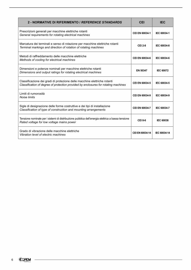
3 - RENDIMENTI
I motori trifase 2 e 4 P Elvem con potenza compresa tra 1,1 e 90 Kw sono a rendimento aumentato EFF2 e riportano in targa il logo registrato .
Le tabelle seguenti riportano l’accordo stabilito tra la Commissione Europea ed il CEMEP (Comitato Europeo Costruttori Macchine Rotanti e Elettronica di Potenza) sul sistema di classiicazione dei motori basato sul rendimento.
3 - EFFICIENCY
Elvem three-phase motors 2 and 4 P with power ranging from 1,1 up 90 Kw are high eficiency motors EFF2 and there is stated the registered mark on name plate.The following diagram shows agreement between European Commission and CEMEP (European Commitee of Manufacturer of Electrical Machines and Power Electronics) on classiication system of electric motors based on eficiency.
Kw EFF3 motors
さ %
EFF2 motors
さ %
EFF1 motors
さ %
1.1 < 76,2 ≥ 76,2 ≥ 82,81.5 < 78,5 ≥ 78,5 ≥ 84,12.2 < 81,0 ≥ 81,0 ≥ 85,63 < 82,6 ≥ 82,6 ≥ 86,74 < 84,6 ≥ 84,6 ≥ 87,6
5.5 < 85,7 ≥ 85,7 ≥ 88,67.5 < 87,0 ≥ 87,0 ≥ 89,511 < 88,4 ≥ 88,4 ≥ 90,515 < 89,4 ≥ 89,4 ≥ 91,3
18.5 < 90,0 ≥ 90,0 ≥ 91,822 < 90,5 ≥ 90,5 ≥ 92,230 < 91,4 ≥ 91,4 ≥ 92,937 < 92,0 ≥ 92,0 ≥ 93,345 < 92,5 ≥ 92,5 ≥ 93,755 < 93,0 ≥ 93,0 ≥ 94,075 < 93,6 ≥ 93,6 ≥ 94,690 < 93,9 ≥ 93,9 ≥ 95,0
Kw EFF3 motors
さ %
EFF2 motors
さ %
EFF1 motors
さ %
1.1 < 76,2 ≥ 76,2 ≥ 83,81.5 < 78,5 ≥ 78,5 ≥ 85,02.2 < 81,0 ≥ 81,0 ≥ 86,43 < 82,6 ≥ 82,6 ≥ 87,44 < 84,6 ≥ 84,6 ≥ 88,3
5.5 < 85,7 ≥ 85,7 ≥ 89,27.5 < 87,0 ≥ 87,0 ≥ 90,111 < 88,4 ≥ 88,4 ≥ 91,015 < 89,4 ≥ 89,4 ≥ 91,8
18.5 < 90,0 ≥ 90,0 ≥ 92,222 < 90,5 ≥ 90,5 ≥ 92,630 < 91,4 ≥ 91,4 ≥ 93,237 < 92,0 ≥ 92,0 ≥ 93,645 < 92,5 ≥ 92,5 ≥ 93,955 < 93,0 ≥ 93,0 ≥ 94,275 < 93,6 ≥ 93,6 ≥ 94,790 < 93,9 ≥ 93,9 ≥ 95,0
ELECTRIC MOTOR EFFICIENCY MOTORI 4 POLI/4 POLE MOTORS MOTORI 2 POLI/2 POLE MOTORS
Vantaggi nell’utilizzo dei motori in EFF1
riduzione dei consumi di energia elettrica. • Es: nel caso di un motore di 15 Kw per 6000 ore/annue di utilizzo, si possono risparmiare circa 4 Mwh per anno (più di 200€ con 0,05 €/Kwh)
riduzione della sovratemperatura del motore e • e quindi incremento della durata dell’isolante, dei cuscinetti e degli altri componenti
vantaggi nelle applicazioni che richiedono • l’impiego di inverter
minore rumorosità•
maggiore resistenza ai sovraccarichi•
Advantages of using EFF1 motors
less consumption of electric energy. E.g.: • using a 15 Kw motor for 6000 hours/year duty, it can be saved about 4 Mwh per year (more than 200 € with 0,05 €/Kwh)
reduction of motor temperature rises: that • means longer life for insulation material, bearings and other components
higher capacities in application where inverter • is required
reduces noise level•
suitable for overloads•
8
3.1 - Calcolo risparmio energetico
Qui di seguito riportiamo il metodo per calcolare agevolmente il risparmio energetico:
3.1 - Energetic saving calculation
Here below how to calculate quickly the energetic savings:
R = h x Kw x %FL x €/Kwh x (¹/さ²% - ¹/さ¹%)
dove:R = risparmio energetico annualeh = ore utilizzo annue motoreKw = potenza motore (Kw)%FL = coeficiente di utilizzo della potenza nominale del motore€/Kwh = costo energiaさ²% = % rendimento del motore EFF2
さ¹% = % rendimento del motore EFF1
where:R = annual saving
h = annual running (hours)Kw = motor rated power (Kw)%FL = fraction of full load power at which motors runs€/Kwh = electricity cost
さ²% = % eficiency of standard motor EFF2
さ¹% = % eficiency of standard motor EFF1
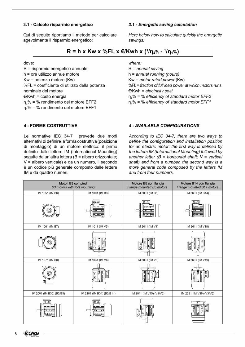
4 - FORME COSTRUTTIVE
Le normative IEC 34-7 prevede due modi alternativi di deinire la forma costruttiva (posizione di montaggio) di un motore elettrico: il primo deinito dalle lettere IM (International Mounting) seguite da un’altra lettera (B = albero orizzontale; V = albero verticale) e da un numero, il secondo è un codice più generale composto dalle lettere IM e da quattro numeri.
4 - AVAILABLE CONFIGURATIONS
According to IEC 34-7, there are two ways to deine the coniguration and installation position for an electric motor: the irst way is deined by the letters IM (International Mounting) followed by another letter (B = horizontal shaft; V = vertical shaft) and from a number, the second way is a more general code composed by the letters IM and from four numbers.
9
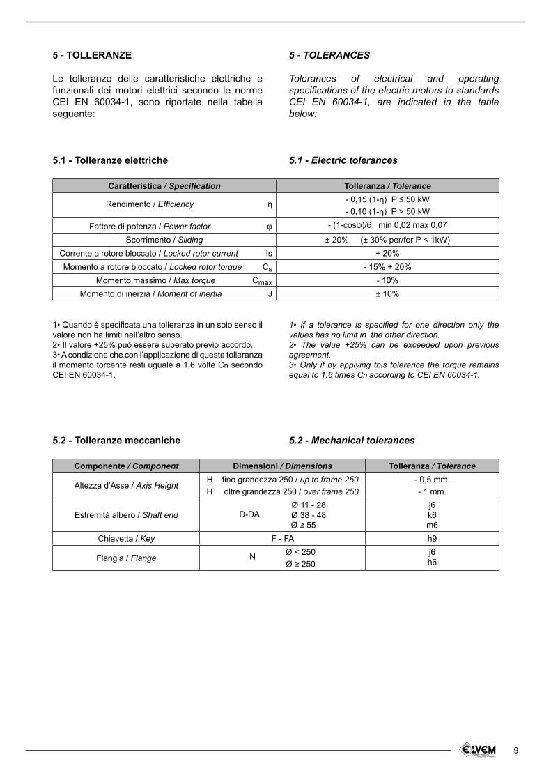
5 - TOLLERANZE
Le tolleranze delle caratteristiche elettriche e funzionali dei motori elettrici secondo le norme CEI EN 60034-1, sono riportate nella tabella seguente:
5.1 - Tolleranze elettriche
5 - TOLERANCES
Tolerances of electrical and operating speciications of the electric motors to standards CEI EN 60034-1, are indicated in the table below:
5.1 - Electric tolerances
Caratteristica / Speciication Tolleranza / Tolerance
Rendimento / Eficiency さ - 0,15 (1-さ) P ≤ 50 kW- 0,10 (1-さ) P > 50 kW
Fattore di potenza / Power factor l - (1-cosl)/6 min 0,02 max 0,07
Scorrimento / Sliding ± 20% (± 30% per/for P < 1kW)Corrente a rotore bloccato / Locked rotor current Is + 20%Momento a rotore bloccato / Locked rotor torque Cs - 15% + 20%
Momento massimo / Max torque Cmax - 10%Momento di inerzia / Moment of inertia J ± 10%
1• Quando è speciicata una tolleranza in un solo senso il valore non ha limiti nell’altro senso.2• Il valore +25% può essere superato previo accordo.3• A condizione che con l’applicazione di questa tolleranza il momento torcente resti uguale a 1,6 volte Cn secondo CEI EN 60034-1.
1• If a tolerance is speciied for one direction only the values has no limit in the other direction.2• The value +25% can be exceeded upon previous agreement.3• Only if by applying this tolerance the torque remains equal to 1,6 times Cn according to CEI EN 60034-1.
Componente / Component Dimensioni / Dimensions Tolleranza / Tolerance
Altezza d’Asse / Axis HeightH fino grandezza 250 / up to frame 250H oltre grandezza 250 / over frame 250
- 0,5 mm.
- 1 mm.
Estremità albero / Shaft end D-DA Ø 11 - 28
Ø 38 - 48 Ø ≥ 55
j6k6m6
Chiavetta / Key F - FA h9
Flangia / Flange N Ø < 250
Ø ≥ 250j6h6
5.2 - Tolleranze meccaniche 5.2 - Mechanical tolerances
10
6 - CARATTERISTICHE MECCANICHE
6.1 - Materiali
6 - MECHANICAL SPECIFICATIONS
6.1 - Materials
Componenti / Components Grandezze / Size Tipo di materiali / Material type
Cassa statore / Stator casing 56-160160-355
alluminio/aluminium *
ghisa/cast iron
Scudo anteriore e posterioreFront and back endshield
56-160160-355
alluminio/aluminium *
ghisa/cast iron
Copriventola / Fan cover 56-355 metallo/metal
Ventola / Cooling fan 56-355 termoplastico/thermoplastic **
Coprimorsettiera / Terminal box 56-160160-355
alluminio/aluminium
ghisa/cast iron
* grandezza 71-132: ghisa su richiesta** alluminio su richiesta
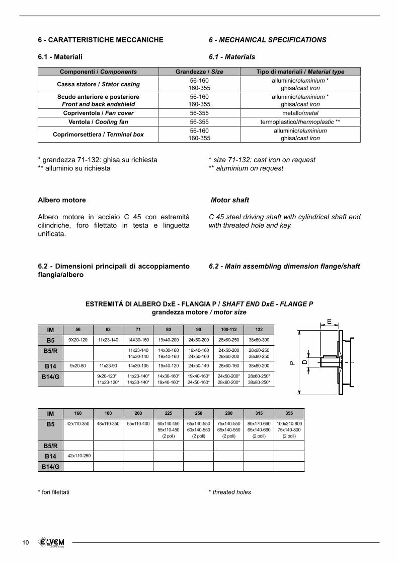
6.2 - Dimensioni principali di accoppiamento langia/albero
Albero motore
Albero motore in acciaio C 45 con estremità cilindriche, foro ilettato in testa e linguetta uniicata.
* size 71-132: cast iron on request** aluminium on request
6.2 - Main assembling dimension lange/shaft
Motor shaft
C 45 steel driving shaft with cylindrical shaft end with threated hole and key.
* fori ilettati * threated holes
ESTREMITÁ DI ALBERO DxE - FLANGIA P / SHAFT END DxE - FLANGE Pgrandezza motore / motor size
B5 9X20-120 11x23-140 14X30-160 19x40-200 24x50-200 28x60-250 38x80-300
B5/R 11x23-14014x30-140
14x30-16019x40-160
19x40-16024x50-160
24x50-20028x60-200
28x60-25038x80-250
B14 9x20-80 11x23-90 14x30-105 19x40-120 24x50-140 28x60-160 38x80-200
B14/G 9x20-120*11x23-120*
11x23-140*14x30-140*
14x30-160*19x40-160*
19x40-160*24x50-160*
24x50-200*28x60-200*
28x60-250*38x80-250*
IM 56 63 71 80 90 100-112 132
B5 42x110-350 48x110-350 55x110-400 60x140-45055x110-450
(2 poli)
65x140-55060x140-550
(2 poli)
75x140-55065x140-550
(2 poli)
80x170-66065x140-660
(2 poli)
100x210-80075x140-800
(2 poli)
B5/R
B14 42x110-250
B14/G
IM 160 180 200 225 250 280 315 355
P
11
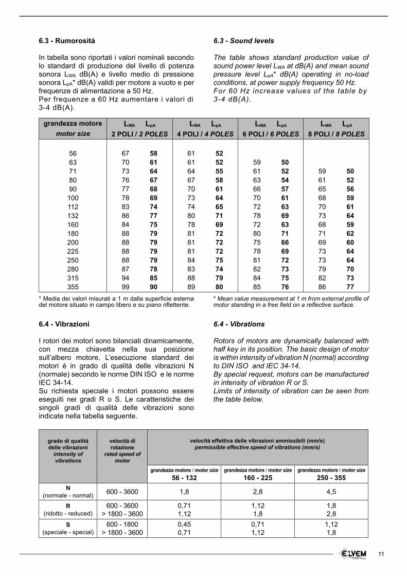
6.3 - Rumorositá
In tabella sono riportati i valori nominali secondo lo standard di produzione del livello di potenza sonora LWA dB(A) e livello medio di pressione sonora LpA* dB(A) validi per motore a vuoto e per frequenze di alimentazione a 50 Hz.Per frequenze a 60 Hz aumentare i valori di3-4 dB(A).
6.3 - Sound levels
The table shows standard production value of sound power level LWA at dB(A) and mean sound pressure level LpA* dB(A) operating in no-load conditions, at power supply frequency 50 Hz.For 60 Hz increase values of the table by3-4 dB(A).
* Media dei valori misurati a 1 m dalla supericie esterna del motore situato in campo libero e su piano rilettente.
* Mean value measurement at 1 m from external proile of motor standing in a free ield on a relective surface.
grandezza motoremotor size
LWA LpA
2 POLI / 2 POLESLWA LpA
4 POLI / 4 POLESLWA LpA
6 POLI / 6 POLESLWA LpA
8 POLI / 8 POLES
5663718090
100112132160180200225250280315355
67707376777883868488888888879499
58616467686974777579797979788590
61616467707374807881818184838889
52525558616465716972727275747980
596163667072787280757881828485
505254576163696371666972737576
5961656870736871697373798286
5052565961645962606464707377
6.4 - Vibrazioni
I rotori dei motori sono bilanciati dinamicamente, con mezza chiavetta nella sua posizione sull’albero motore. L’esecuzione standard dei motori è in grado di qualità delle vibrazioni N (normale) secondo le norme DIN ISO e le norme IEC 34-14.Su richiesta speciale i motori possono essere eseguiti nei gradi R o S. Le caratteristiche dei singoli gradi di qualità delle vibrazioni sono indicate nella tabella seguente.
6.4 - Vibrations
Rotors of motors are dynamically balanced with half key in its position. The basic design of motor is within intensity of vibration N (normal) according to DIN ISO and IEC 34-14.By special request, motors can be manufactured in intensity of vibration R or S.Limits of intensity of vibration can be seen from the table below.
grado di qualità delle vibrazioni
intensity ofvibrations
velocità dirotazione
rated speed of motor
grandezza motore / motor size56 - 132
grandezza motore / motor size
160 - 225grandezza motore / motor size
250 - 355
N(normale - normal)
600 - 3600 1,8 2,8 4,5
R(ridotto - reduced)
600 - 3600> 1800 - 3600
0,711,12
1,121,8
1,82,8
S(speciale - special)
600 - 1800> 1800 - 3600
0,450,71
0,711,12
1,121,8
velocità effettiva delle vibrazioni ammissibili (mm/s) permissible effective speed of vibrations (mm/s)
12
6.5 - Verniciatura
Lo strato inale della vernice è in sfumatura RAL 5010. Su richiesta speciale è possibile eseguire la verniciatura inale in altre sfumature.
6.5 - Finishing coat
Finishing coat of paint is in the color shade RAL 5010. By special request inishing coat of paint can be performed in other color shade.
6.6 - Protezione contro la corrosione
Per garantire l’elevata resistenza alla corrosione di tutte le superici metalliche eseguiamo una accurata selezione dei materiali: tutte le superici sono sabbiate, sgrassate quindi controllate accuratamente.L’estremità libera dell’albero e di tutte le sedi sono protette dalla corrosione con i mezzi di protezione provvisoria.Su richiesta possiamo applicare la protezione speciica per l’utilizzo in ambienti particolarmente agressivi (ad es. zone tropicali, atmosfera ad alta concentrazione salina, ecc.).
6.6 - Corrosion protection
All materials are selected to ensure high resistance to corrosion: the metallic surfaces is sand-blasted, degreased and therefore checked carefully. All the housings and drive end of the shaft are protected with temporary corrosion inhibitor. By special request, we can apply speciic protection for harsh environments (e.g. tropical area, high saline concentration...).
13
6.7 - Grado di protezione IP
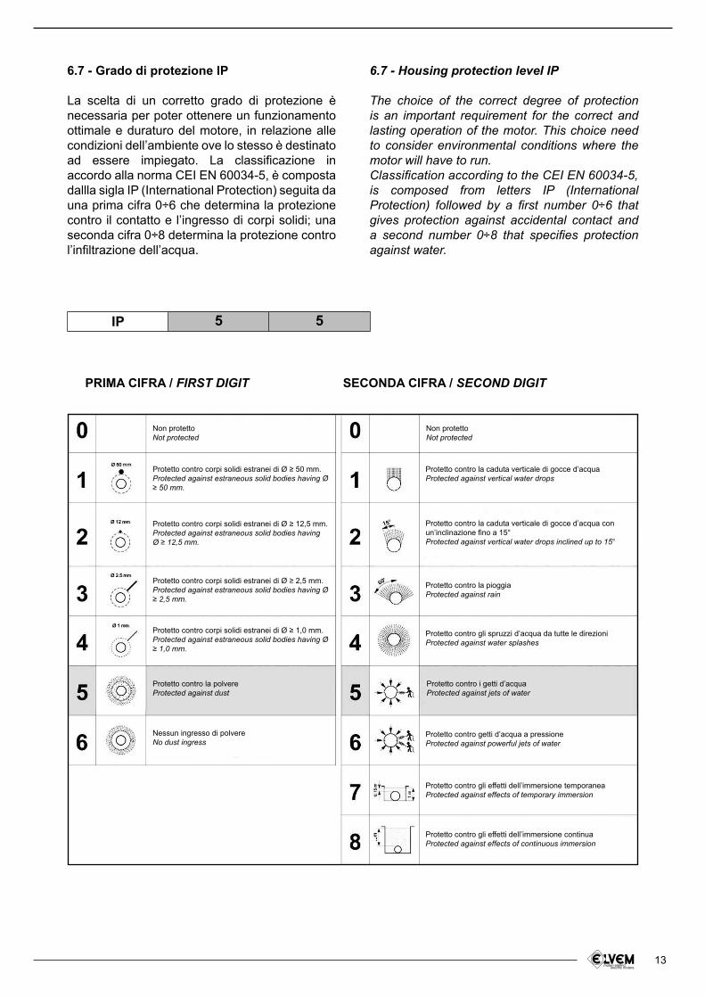
La scelta di un corretto grado di protezione è necessaria per poter ottenere un funzionamento ottimale e duraturo del motore, in relazione alle condizioni dell’ambiente ove lo stesso è destinato ad essere impiegato. La classiicazione in accordo alla norma CEI EN 60034-5, è composta dallla sigla IP (International Protection) seguita da una prima cifra 0÷6 che determina la protezione contro il contatto e l’ingresso di corpi solidi; una seconda cifra 0÷8 determina la protezione contro l’iniltrazione dell’acqua.
6.7 - Housing protection level IP
The choice of the correct degree of protection is an important requirement for the correct and lasting operation of the motor. This choice need to consider environmental conditions where the motor will have to run.Classiication according to the CEI EN 60034-5,is composed from letters IP (International Protection) followed by a irst number 0÷6 that gives protection against accidental contact and a second number 0÷8 that speciies protection against water.
PRIMA CIFRA / FIRST DIGIT SECONDA CIFRA / SECOND DIGIT
IP 5 5
Non protettoNot protected
Non protettoNot protected
Protetto contro la polvereProtected against dust
Protetto contro i getti d’acquaProtected against jets of water
Nessun ingresso di polvereNo dust ingress
Protetto contro corpi solidi estranei di Ø ≥ 50 mm.Protected against estraneous solid bodies having Ø ≥ 50 mm.
Protetto contro la caduta verticale di gocce d’acquaProtected against vertical water drops
Protetto contro la caduta verticale di gocce d’acqua con un’inclinazione ino a 15°Protected against vertical water drops inclined up to 15°
Protetto contro la pioggiaProtected against rain
Protetto contro gli spruzzi d’acqua da tutte le direzioniProtected against water splashes
Protetto contro getti d’acqua a pressioneProtected against powerful jets of water
Protetto contro gli effetti dell’immersione temporaneaProtected against effects of temporary immersion
Protetto contro gli effetti dell’immersione continuaProtected against effects of continuous immersion
Protetto contro corpi solidi estranei di Ø ≥ 12,5 mm.Protected against estraneous solid bodies havingØ ≥ 12,5 mm.
Protetto contro corpi solidi estranei di Ø ≥ 2,5 mm.Protected against estraneous solid bodies having Ø ≥ 2,5 mm.
Protetto contro corpi solidi estranei di Ø ≥ 1,0 mm.Protected against estraneous solid bodies having Ø ≥ 1,0 mm.
14
7 - CARATTERISTICHE ELETTRICHE
7.1 - Isolamento ed avvolgimento statorico
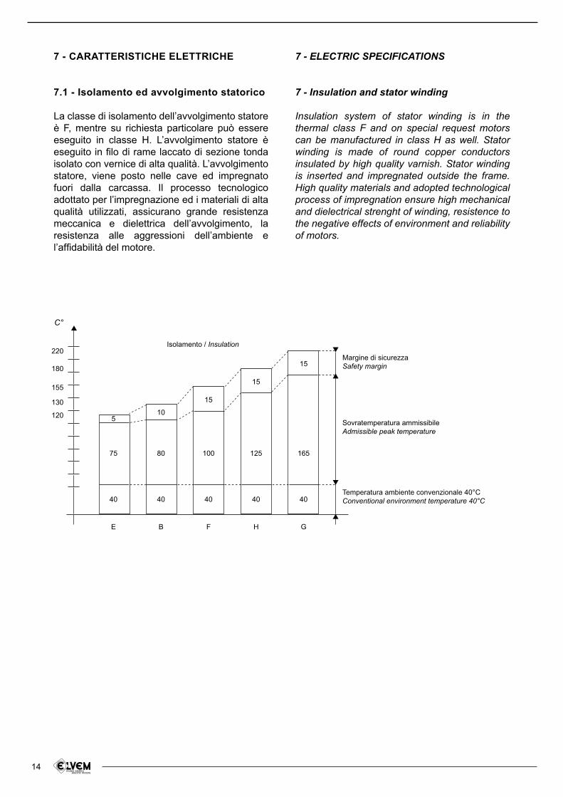
La classe di isolamento dell’avvolgimento statore è F, mentre su richiesta particolare può essere eseguito in classe H. L’avvolgimento statore è eseguito in ilo di rame laccato di sezione tonda isolato con vernice di alta qualità. L’avvolgimento statore, viene posto nelle cave ed impregnato fuori dalla carcassa. Il processo tecnologico adottato per l’impregnazione ed i materiali di alta qualità utilizzati, assicurano grande resistenza meccanica e dielettrica dell’avvolgimento, la resistenza alle aggressioni dell’ambiente e l’afidabilità del motore.
7 - ELECTRIC SPECIFICATIONS
7 - Insulation and stator winding
Insulation system of stator winding is in the thermal class F and on special request motors can be manufactured in class H as well. Stator winding is made of round copper conductors insulated by high quality varnish. Stator winding is inserted and impregnated outside the frame. High quality materials and adopted technological process of impregnation ensure high mechanical and dielectrical strenght of winding, resistence to the negative effects of environment and reliability of motors.
120
130
E B F H G
40 40 40 40 40
75 80 100 125 165
510
15
15
15Margine di sicurezza
Safety margin
Isolamento / Insulation
Sovratemperatura ammissibile
Admissible peak temperature
Temperatura ambiente convenzionale 40°C
Conventional environment temperature 40°C
155
180
220
C°
15
7.2 - Variazione potenza per condizioni ambientali
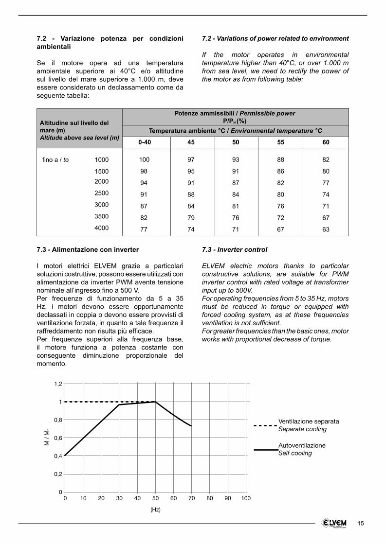
Se il motore opera ad una temperatura ambientale superiore ai 40°C e/o altitudine sul livello del mare superiore a 1.000 m, deve essere considerato un declassamento come da seguente tabella:
7.2 - Variations of power related to environment
If the motor operates in environmental temperature higher than 40°C, or over 1.000 m from sea level, we need to rectify the power of the motor as from following table:
Altitudine sul livello del
mare (m)
Altitude above sea level (m)
Potenze ammissibili / Permissible power
P/PN (%)
Temperatura ambiente °C / Environmental temperature °C
2000
1500
1000fino a / to
2500
3000
3500
4000
0-40
100
98
94
91
87
82
77
45
97
95
91
88
84
79
74
50
93
91
87
84
81
76
71
55
88
86
82
80
76
72
67
60
82
80
77
74
71
67
63
7.3 - Alimentazione con inverter
I motori elettrici ELVEM grazie a particolari soluzioni costruttive, possono essere utilizzati con alimentazione da inverter PWM avente tensione nominale all’ingresso ino a 500 V.Per frequenze di funzionamento da 5 a 35 Hz, i motori devono essere opportunamente declassati in coppia o devono essere provvisti di ventilazione forzata, in quanto a tale frequenze il raffreddamento non risulta più eficace.Per frequenze superiori alla frequenza base, il motore funziona a potenza costante con conseguente diminuzione proporzionale del momento.
7.3 - Inverter control
ELVEM electric motors thanks to particolar constructive solutions, are suitable for PWM inverter control with rated voltage at transformer input up to 500V.For operating frequencies from 5 to 35 Hz, motors must be reduced in torque or equipped with forced cooling system, as at these frequencies ventilation is not suficient.For greater frequencies than the basic ones, motor works with proportional decrease of torque.
1,2
1
0,8
0,6
M /
MN
0,4
0,2
00 10 20 30 40 50
(Hz)
Ventilazione separata
Separate cooling
Autoventilazione
Self cooling
60 70 80 90 100
16
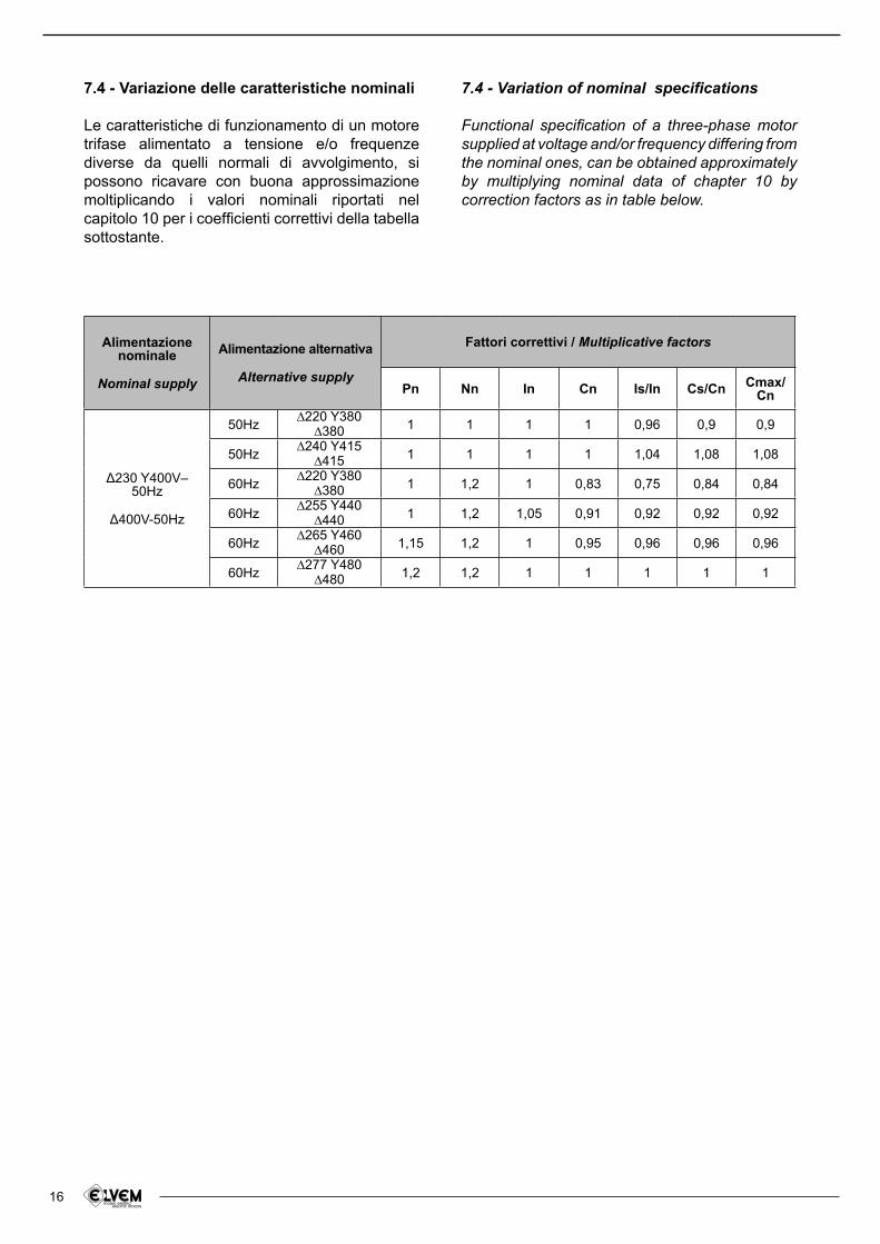
7.4 - Variazione delle caratteristiche nominali
Le caratteristiche di funzionamento di un motore trifase alimentato a tensione e/o frequenze diverse da quelli normali di avvolgimento, si possono ricavare con buona approssimazione moltiplicando i valori nominali riportati nel capitolo 10 per i coeficienti correttivi della tabella sottostante.
7.4 - Variation of nominal speciications
Functional speciication of a three-phase motor supplied at voltage and/or frequency differing from the nominal ones, can be obtained approximately by multiplying nominal data of chapter 10 by correction factors as in table below.
Alimentazione nominale
Nominal supply
Alimentazione alternativa
Alternative supply
Fattori correttivi / Multiplicative factors
Pn Nn In Cn Is/In Cs/Cn Cmax/ Cn
〉230 Y400V–50Hz
〉400V-50Hz
50Hz∆220 Y380
∆380 1 1 1 1 0,96 0,9 0,9
50Hz∆240 Y415
∆415 1 1 1 1 1,04 1,08 1,08
60Hz∆220 Y380
∆380 1 1,2 1 0,83 0,75 0,84 0,84
60Hz∆255 Y440
∆440 1 1,2 1,05 0,91 0,92 0,92 0,92
60Hz∆265 Y460
∆460 1,15 1,2 1 0,95 0,96 0,96 0,96
60Hz∆277 Y480
∆480 1,2 1,2 1 1 1 1 1
17
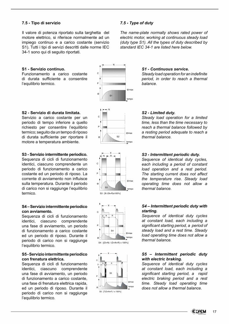
S1 - Servizio continuo.Funzionamento a carico costante di durata suficiente a consentire l’equilibrio termico.
S2 - Servizio di durata limitata.Servizio a carico costante per un periodo di tempo inferiore a quello richiesto per consentire l’equilibrio termico; seguito da un tempo di riposo di durata suficiente per riportare il motore a temperatura ambiente.
S3 - Servizio intermittente periodico.Sequenza di cicli di funzionamento identici, ciascuno comprendente un periodo di funzionamento a carico costante ed un periodo di riposo. La corrente di avviamento non inluisce sulla temperatura. Durante il periodo di carico non si raggiunge l’equilibrio termico.
S4 – Servizio intermittente periodico con avviamento. Sequenza di cicli di funzionamento identici, ciascuno comprendente una fase di avviamento, un periodo di funzionamento a carico costante ed un periodo di riposo. Durante il periodo di carico non si raggiunge l’equilibrio termico.
S5 - Servizio intermittente periodico con frenatura elettrica.Sequenza di cicli di funzionamento identici, ciascuno comprendente una fase di avviamento, un periodo di funzionamento a carico costante, una fase di frenatura elettrica rapida, ed un periodo di riposo. Durante il periodo di carico non si raggiunge l’equilibrio termico.
S1 - Continuous service.Steady load operation for an indeinite period, in order to reach a thermal balance.
S2 - Limited duty.Steady load operation for a limited time, less than the time necessary to reach a thermal balance followed by a resting period adequate to reach a thermal balance.
S3 - Intermittent periodic duty.Sequence of identical duty cycles, each including a period of constant load operation and a rest period. The starting current does not affect the temperature rise. Steady load operating time does not allow a thermal balance.
S4 – Intermittent periodic duty with starting.Sequence of identical duty cycles at constant load, each including a signiicant starting period, a period of steady load and a rest time. Steady load operating time does not allow a thermal balance.
S5 – Intermittent periodic duty with electric braking.Sequence of identical duty cycles at constant load, each including a signiicant starting period, a rapid electric braking period and a rest time. Steady load operating time does not allow a thermal balance.
S1
tempo
max
N
P
C
O-
O-
θ
θ
θ
S2
tempo
max
P
C
N
O-
O-
θ
θ
θ
S3 : [N /(N+R)x100%]
tempo
max
S3
N R
X
P
C
O-
O-
θ
θ
θ
S4 : [(D+N) / (D+N+R) x 100%]
tempo
maxS4
X
D N R
P
C
O-
O-
θ
θ
θ
S5 : [T(D+N+F) / x 100%]
tempo
max
S5
X
DN
F
R
P
C
O-
O-
θ
θ
θ
7.5 - Tipo di servizio
Il valore di potenza riportato sulla targhetta del motore elettrico, si riferisce normalmente ad un impiego continuo e a carico costante (servizio S1). Tutti i tipi di servizi descritti dalle norme IEC 34-1 sono qui di seguito riportati.
7.5 - Type of duty
The name-plate normally shows rated power of electric motor, working at continuous steady load (duty type S1). All the types of duty described by standard IEC 34-1 are listed here below.
18
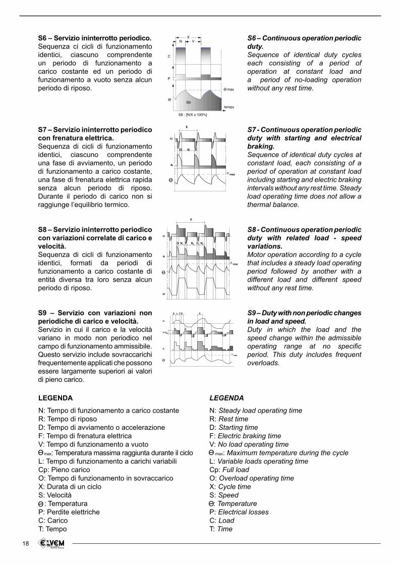
S6 – Servizio ininterrotto periodico.Sequenza ci cicli di funzionamento identici, ciascuno comprendente un periodo di funzionamento a carico costante ed un periodo di funzionamento a vuoto senza alcun periodo di riposo.
S7 – Servizio ininterrotto periodico con frenatura elettrica.Sequenza di cicli di funzionamento identici, ciascuno comprendente una fase di avviamento, un periodo di funzionamento a carico costante, una fase di frenatura elettrica rapida senza alcun periodo di riposo.Durante il periodo di carico non si raggiunge l’equilibrio termico.
S8 – Servizio ininterrotto periodico con variazioni correlate di carico e velocità.Sequenza di cicli di funzionamento identici, formati da periodi di funzionamento a carico costante di entità diversa tra loro senza alcun periodo di riposo.
S9 – Servizio con variazioni non periodiche di carico e velocità.Servizio in cui il carico e la velocità variano in modo non periodico nel campo di funzionamento ammissibile. Questo servizio include sovraccarichi frequentemente applicati che possono essere largamente superiori ai valori di pieno carico.
S6 – Continuous operation periodic duty.Sequence of identical duty cycles each consisting of a period of operation at constant load and a period of no-loading operation without any rest time.
S7 - Continuous operation periodic duty with starting and electrical braking.Sequence of identical duty cycles at constant load, each consisting of a period of operation at constant load including starting and electric braking intervals without any rest time. Steady load operating time does not allow a thermal balance.
S8 - Continuous operation periodic duty with related load - speed variations.Motor operation according to a cycle that includes a steady load operating period followed by another with a different load and different speed without any rest time.
S9 – Duty with non periodic changes in load and speed.Duty in which the load and the speed change within the admissible operating range at no speciic period. This duty includes frequent overloads.
S6 : [N/X x 100%]
tempo
max
S6
N VX
P
C
O-
O-
θ
θ
θ
X
θ maxC
P
D N F
θ
O-
θ
θ
D F R S
θ max
SC
P
Cp
L
O-
θ
θ
θ
O-
X
θ max
SC
P
D N1 F1 N2 N3F2
LEGENDA
N: Tempo di funzionamento a carico costanteR: Tempo di riposoD: Tempo di avviamento o accelerazioneF: Tempo di frenatura elettricaV: Tempo di funzionamento a vuoto max: Temperatura massima raggiunta durante il cicloL: Tempo di funzionamento a carichi variabiliCp: Pieno caricoO: Tempo di funzionamento in sovraccaricoX: Durata di un cicloS: Velocità : TemperaturaP: Perdite elettricheC: CaricoT: Tempo
LEGENDA
N: Steady load operating timeR: Rest timeD: Starting timeF: Electric braking timeV: No load operating time max: Maximum temperature during the cycleL: Variable loads operating timeCp: Full loadO: Overload operating timeX: Cycle timeS: Speed : TemperatureP: Electrical lossesC: LoadT: Time
O-
θ
θ
θ
O-
θ
θ
θ
O-
θ
θ
θ
O-
θ
θ
θ
19
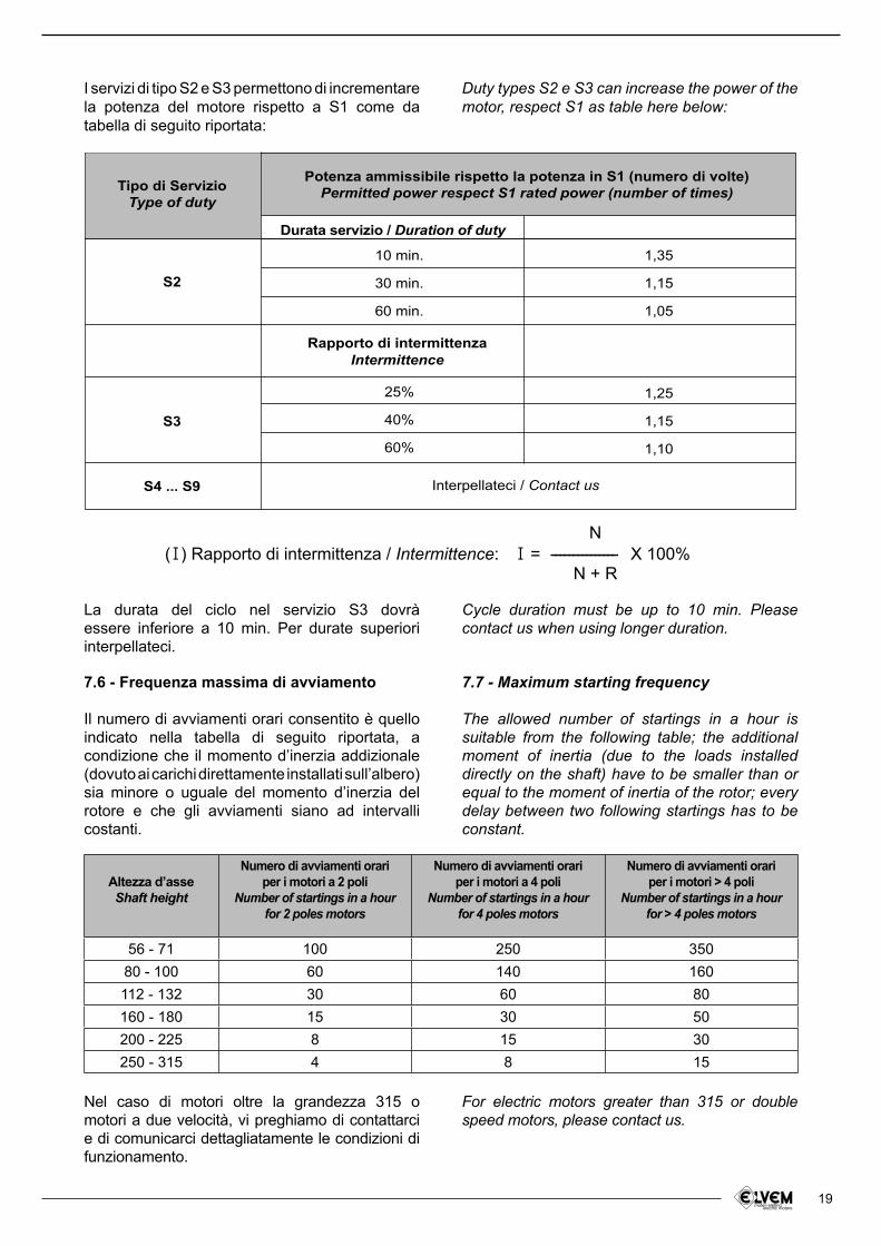
I servizi di tipo S2 e S3 permettono di incrementare la potenza del motore rispetto a S1 come da tabella di seguito riportata:
Duty types S2 e S3 can increase the power of the motor, respect S1 as table here below:
Tipo di Servizio
Type of duty
Potenza ammissibile rispetto la potenza in S1 (numero di volte)
Permitted power respect S1 rated power (number of times)
S2
Durata servizio / Duration of duty
Rapporto di intermittenza
Intermittence
Interpellateci / Contact us
10 min.
30 min.
60 min.
25%
40%
60%
1,35
1,15
1,05
1,25
1,15
1,10
S3
S4 ... S9
(I) Rapporto di intermittenza / Intermittence:N
N + RI = --------------- X 100%
7.7 - Maximum starting frequency
The allowed number of startings in a hour is suitable from the following table; the additional moment of inertia (due to the loads installed directly on the shaft) have to be smaller than or equal to the moment of inertia of the rotor; every delay between two following startings has to be constant.
Cycle duration must be up to 10 min. Please contact us when using longer duration.
For electric motors greater than 315 or double speed motors, please contact us.
La durata del ciclo nel servizio S3 dovrà essere inferiore a 10 min. Per durate superiori interpellateci.
Nel caso di motori oltre la grandezza 315 o motori a due velocità, vi preghiamo di contattarci e di comunicarci dettagliatamente le condizioni di funzionamento.
7.6 - Frequenza massima di avviamento
Il numero di avviamenti orari consentito è quello indicato nella tabella di seguito riportata, a condizione che il momento d’inerzia addizionale (dovuto ai carichi direttamente installati sull’albero) sia minore o uguale del momento d’inerzia del rotore e che gli avviamenti siano ad intervalli costanti.
Altezza d’asse Shaft height
Numero di avviamenti orariper i motori a 2 poli
Number of startings in a hourfor 2 poles motors
Numero di avviamenti orariper i motori a 4 poli
Number of startings in a hourfor 4 poles motors
Numero di avviamenti orariper i motori > 4 poli
Number of startings in a hourfor > 4 poles motors
56 - 71 100 250 350
80 - 100 60 140 160
112 - 132 30 60 80
160 - 180 15 30 50
200 - 225 8 15 30
250 - 315 4 8 15
20
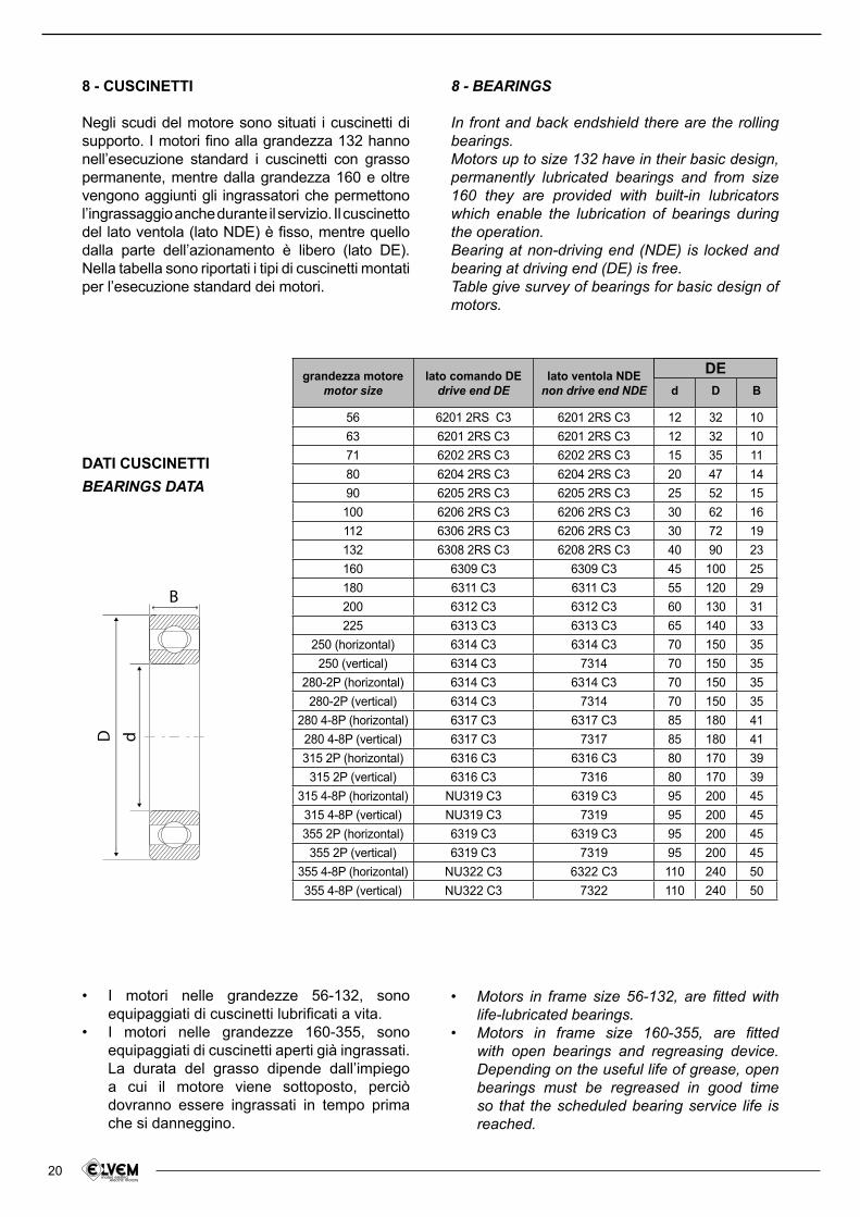
I motori nelle grandezze 56-132, sono • equipaggiati di cuscinetti lubriicati a vita.I motori nelle grandezze 160-355, sono • equipaggiati di cuscinetti aperti già ingrassati. La durata del grasso dipende dall’impiego a cui il motore viene sottoposto, perciò dovranno essere ingrassati in tempo prima che si danneggino.
8 - CUSCINETTI
Negli scudi del motore sono situati i cuscinetti di supporto. I motori ino alla grandezza 132 hanno nell’esecuzione standard i cuscinetti con grasso permanente, mentre dalla grandezza 160 e oltre vengono aggiunti gli ingrassatori che permettono l’ingrassaggio anche durante il servizio. Il cuscinetto del lato ventola (lato NDE) è isso, mentre quello dalla parte dell’azionamento è libero (lato DE). Nella tabella sono riportati i tipi di cuscinetti montati per l’esecuzione standard dei motori.
8 - BEARINGS
In front and back endshield there are the rolling bearings.Motors up to size 132 have in their basic design, permanently lubricated bearings and from size 160 they are provided with built-in lubricators which enable the lubrication of bearings during the operation.Bearing at non-driving end (NDE) is locked and bearing at driving end (DE) is free.Table give survey of bearings for basic design of motors.
Motors in frame size 56-132, are itted with • life-lubricated bearings.Motors in frame size 160-355, are itted • with open bearings and regreasing device. Depending on the useful life of grease, open bearings must be regreased in good time so that the scheduled bearing service life is reached.
DATI CUSCINETTI
BEARINGS DATA
grandezza motoremotor size
lato comando DEdrive end DE
lato ventola NDEnon drive end NDE d D B
56 6201 2RS C3 6201 2RS C3 12 32 10
63 6201 2RS C3 6201 2RS C3 12 32 10
71 6202 2RS C3 6202 2RS C3 15 35 11
80 6204 2RS C3 6204 2RS C3 20 47 14
90 6205 2RS C3 6205 2RS C3 25 52 15
100 6206 2RS C3 6206 2RS C3 30 62 16
112 6306 2RS C3 6206 2RS C3 30 72 19
132 6308 2RS C3 6208 2RS C3 40 90 23
160 6309 C3 6309 C3 45 100 25
180 6311 C3 6311 C3 55 120 29
200 6312 C3 6312 C3 60 130 31
225 6313 C3 6313 C3 65 140 33
250 (horizontal) 6314 C3 6314 C3 70 150 35
250 (vertical) 6314 C3 7314 70 150 35
280-2P (horizontal) 6314 C3 6314 C3 70 150 35
280-2P (vertical) 6314 C3 7314 70 150 35
280 4-8P (horizontal) 6317 C3 6317 C3 85 180 41
280 4-8P (vertical) 6317 C3 7317 85 180 41
315 2P (horizontal) 6316 C3 6316 C3 80 170 39
315 2P (vertical) 6316 C3 7316 80 170 39
315 4-8P (horizontal) NU319 C3 6319 C3 95 200 45
315 4-8P (vertical) NU319 C3 7319 95 200 45
355 2P (horizontal) 6319 C3 6319 C3 95 200 45
355 2P (vertical) 6319 C3 7319 95 200 45
355 4-8P (horizontal) NU322 C3 6322 C3 110 240 50
355 4-8P (vertical) NU322 C3 7322 110 240 50
D d
B
DE
21
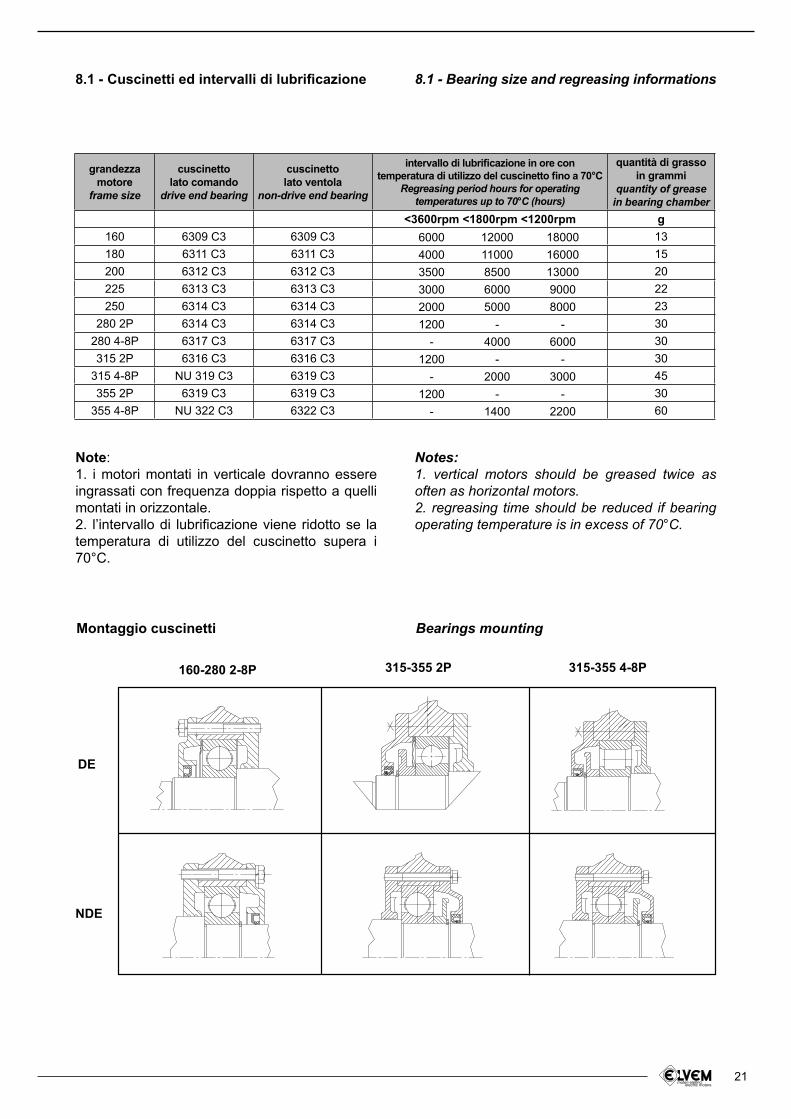
8.1 - Cuscinetti ed intervalli di lubriicazione 8.1 - Bearing size and regreasing informations
Note:1. i motori montati in verticale dovranno essere ingrassati con frequenza doppia rispetto a quelli montati in orizzontale.2. l’intervallo di lubriicazione viene ridotto se la temperatura di utilizzo del cuscinetto supera i 70°C.
Notes:1. vertical motors should be greased twice as often as horizontal motors.2. regreasing time should be reduced if bearing operating temperature is in excess of 70°C.
Montaggio cuscinetti Bearings mounting
grandezzamotore
frame size
cuscinettolato comando
drive end bearing
cuscinettolato ventola
non-drive end bearing
intervallo di lubriicazione in ore con temperatura di utilizzo del cuscinetto ino a 70°C
Regreasing period hours for operating temperatures up to 70°C (hours)
quantità di grasso in grammi
quantity of grease in bearing chamber
<3600rpm <1800rpm <1200rpm g
160 6309 C3 6309 C3 13
180 6311 C3 6311 C3 15
200 6312 C3 6312 C3 20
225 6313 C3 6313 C3 22
250 6314 C3 6314 C3 23
280 2P 6314 C3 6314 C3 30
280 4-8P 6317 C3 6317 C3 30
315 2P 6316 C3 6316 C3 30
315 4-8P NU 319 C3 6319 C3 45
355 2P 6319 C3 6319 C3 30
355 4-8P NU 322 C3 6322 C3 60
6000
4000
3500
3000
2000
1200
-
1200
-
1200
-
12000
11000
8500
6000
5000
-
4000
-
2000
-
1400
18000
16000
13000
9000
8000
-
6000
-
3000
-
2200
DE
NDE
160-280 2-8P 315-355 2P 315-355 4-8P

22
8.2 - Carichi radiali ed assiali sull’estremitá dell’albero
Se il collegamento tra motore e macchina è realizzato con una trasmissione che genera carichi radiali sull’estremità dell’albero, è necessario veriicare che questi siano minori o uguali a quelli riportati nella tabella sottostante.Il carico radiale si ricava da:
dove:
P è la potenza richiesta dal motore (Kw)n è la velocità angolare (min -1)d è il diametro primitivo (m)C è un coeficiente che assume un valore diverso a seconda del tipo di trasmissione:
C= 1 per trasmissione a catenaC= 1,1 per trasmissione ad ingranaggioC= 1,5 per trasmissione a cinghia dentataC= 2,5 per trasmissione a cinghia trapezoidale
where:
P is motor power required (Kw)n is the speed (min -1)d is the pitch diameter (m)C is a coeficient assuming different value according to the drive type:
C= 1 for chain driveC= 1,1 for gear pair driveC= 1,5 for toothed belt driveC= 2,5 for V-belt drive
8.2 - Radial and axial loads on shaft end
If connection between motor and drive machine is generating radial loads on the shaft end, must be less than or equal to those given in the following table.The radial load Fr is given from:
Nella tabella sono indicati i valori massimi ammissibili per i carichi radiali ed assiali che agiscono sull’estremità dell’albero motore (Fr agente in mezzeria albero), calcolati per una durata pari a 20000 ore. Per durate superiori, i valori riportati devono essere moltiplicati per opportuni coeficienti correttivi.
Values in table below, are the maximum loads that can be applied on shaft end (Fr working on the middle of shaft end), calculated for a working period of 20000 hours. For longer periods, all the values must be corrected by speciic coeficients.
Fr =
C • 19100 • P
n • d--------------------- (N)
Fr
Fa1
Fa2
Taglia motoreFrame size
rpm 3000 1500 1000 750 3000 1500 1000 750 3000 1500 1000 750
56 275 360 120 160 120 160
63 300 375 400 120 160 200 120 160 200
71 330 410 480 500 200 250 300 320 200 250 300 320
80 550 690 800 900 260 340 400 460 260 340 400 460
90 600 770 880 980 340 460 570 650 340 460 570 650
100 880 1100 1250 1400 480 590 750 850 480 590 750 850
112 1000 1200 1400 1500 480 590 750 850 600 700 900 1000
132 1350 1700 1950 2200 600 1000 1300 1500 800 1300 1700 1850
160 2300 2700 3000 3200 1300 1500 1900 2200 1300 1500 1900 2200
180 3000 4000 4600 5300 2400 2700 3000 3300 2400 2700 3000 3300
200 3800 4800 5500 6000 3000 3900 4800 5400 3000 3900 4800 5400
225 4200 5200 6000 6600 3600 4900 5700 6500 3600 4900 5700 6500
250 4800 6000 6900 7600 4100 5500 6500 7300 4175 5500 6500 7300
280 4800 7800 8900 9800 4100 6800 8100 9100 4100 6800 8100 9100
315 5800 15000 16000 17500 4600 7800 9000 10100 4600 7800 9000 10100
355 7700 19000 19000 19000 5800 9900 11500 13000 5800 9900 11500 13000
Fr (N) Fa¹ (N)s
Fa² (N)q
23
9.1 - Scelta del freno
La scelta del freno in termini di coppia frenante Cf necessaria per una determinata applicazione è subordinata alla conoscenza dei dati di progetto. Tali dati sono i seguenti:1) L’inerzia complessiva totale Jtot (Kgm²) delle parti rotanti ridotte all’albero motore;2) Il numero di giri massimo di rotazione del motore n (giri al minuto);3) Il tempo massimo ammesso per la frenatura tf (secondi);4) La coppia agente sul sistema CL (Nm) che può essere rappresentata, ad esempio, da un carico da sollevare oppure da un momento resistente;5) La frequenza operativa del freno, ovvero il numero di manovre eseguite dal freno in un’ora m (1/h). Oltre a questi, altri dati, quali la temperatura media dell’ambiente, le condizioni ambientali speciiche (es. umidità, polvere etc.) e la posizione di montaggio del motore, risultano utili per determinare il più eficiente modo di funzionamento del freno.
Criteri di selezione
Per la deinizione della coppia frenante sono stati individuati quattro casi che si presentano con maggior frequenza:A) Sollevamento di un peso P (N) avente rispetto all’asse di rotazione un momento CL;B) Discesa di un peso P (N) avente rispetto all’asse di rotazione un momento CL;C) Coppia costante resistente CL (Nm) che si oppone alla rotazione del motore;D) Coppia costante resistente CL (Nm) che favorisce la rotazione del motore.Nelle formule utilizzate vengono calcolate alcune quantità che servono per veriicare l’applicazione, in accordo con le tabelle ed i graici riportati nelle pagine del catalogo. Tali formule sono:S coeficiente di sicurezza (deve essere S ≥ 2);Ct coeficiente di riduzione del tempo di intervento (mediamente pari a 0,995);L lavoro per manovra (Joule) che deve essere dissipato in calore dal freno.
9.1 - Choice of the brake
The choice of the brake, according to the braking torque Cf necessary for a special application, depends on the knowledge of the project data. These are:1) The total inertia Jtot (kgm²) of the rotating parts reduced with respect to the motor shaft;2) The greatest number of motor revolutions n (rpm);3) The maximum time allowed for braking the system tf (seconds);4) The torque CL (Nm) acting on the system, which can be a load to be lifted up or a moment of resistance;5) The operating frequency of the brake, or working of the brake within 1 hour m (1/h).There are also other aspects that can determine the best performances of the brake, such as the average room temperature, the speciic environment conditions (humidity, dust, etc) and the assembling position of the motor.
Selection Criteria
In order to deine the braking torque there are four frequent events:A) lifting of a load P (N) which has with respect to the rotation axis a moment CL;B) descent of a load P (N) which has with respect to the rotation axis a moment CL;C) steady resisting torque CL (Nm), which is opposed to the motor rotation;D) steady resisting torque CL (Nm), which favours the motor rotation.We also use some expressions which are already deined, in order to check the application according to the chart and graphics reported in this catalogue:S safety coeficient (S≥ 2);ct brake operating decreasing coeficient (usually equal to 0,995);L work per operation (Joule), or heat that the brake must dissipate during operation.
9 - MOTORI AUTOFRENANTI 9 - BRAKE MOTORS
Calcolo della coppia frenante necessaria
La coppia frenante necessaria è calcolata utilizzando le formule sotto indicate. Moltiplicando il risultato di tali formule per il coeficiente di sicurezza S, generalmente pari a 2, si ottiene la coppia frenante desiderata.
Braking torque calculation
Use the following formulae to calculate the necessary braking torque. You can obtain the wanted braking torque multiplying the result by the safety coeficient S, generally equal to 2.
24
( )
( )
Formula 1 (casi A e C)
Formula 4 (caso A)
Formula 5 (caso B)
Formula 6 (casi C e D)
Formula 2 (casi B e D)
Formula 3
Formula 1 (events A and C)
Formula 4 (events A)
Formula 5 (events B)
Formula 6 (events C and D)
Formula 2 (events B and D)
Formula 3
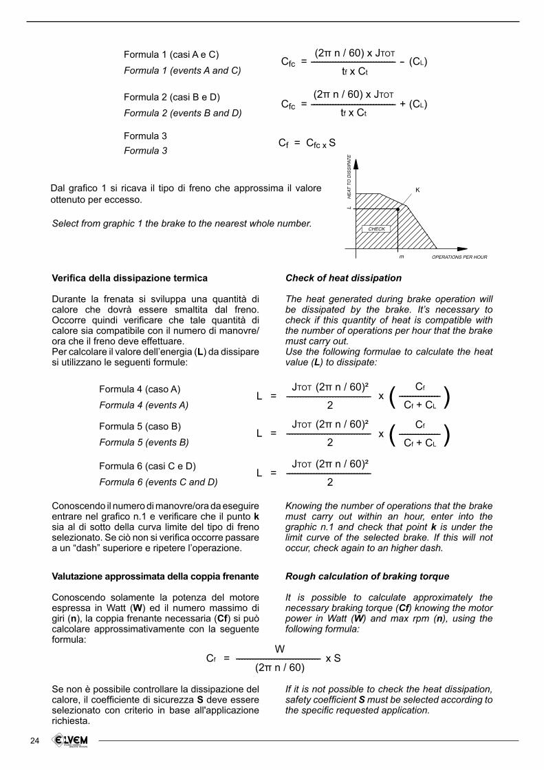
Dal graico 1 si ricava il tipo di freno che approssima il valore ottenuto per eccesso.
Select from graphic 1 the brake to the nearest whole number.
Veriica della dissipazione termica
Durante la frenata si sviluppa una quantità di calore che dovrà essere smaltita dal freno. Occorre quindi veriicare che tale quantità di calore sia compatibile con il numero di manovre/ora che il freno deve effettuare.Per calcolare il valore dell’energia (L) da dissipare si utilizzano le seguenti formule:
Conoscendo il numero di manovre/ora da eseguire entrare nel graico n.1 e veriicare che il punto k sia al di sotto della curva limite del tipo di freno selezionato. Se ciò non si veriica occorre passare a un “dash” superiore e ripetere l’operazione.
Valutazione approssimata della coppia frenante
Conoscendo solamente la potenza del motore espressa in Watt (W) ed il numero massimo di giri (n), la coppia frenante necessaria (Cf) si può calcolare approssimativamente con la seguente formula:
Se non è possibile controllare la dissipazione del calore, il coeficiente di sicurezza S deve essere selezionato con criterio in base all'applicazione richiesta.
Knowing the number of operations that the brake must carry out within an hour, enter into the graphic n.1 and check that point k is under the limit curve of the selected brake. If this will not occur, check again to an higher dash.
Rough calculation of braking torque
It is possible to calculate approximately the necessary braking torque (Cf) knowing the motor power in Watt (W) and max rpm (n), using the following formula:
If it is not possible to check the heat dissipation, safety coeficient S must be selected according to the speciic requested application.
Check of heat dissipation
The heat generated during brake operation will be dissipated by the brake. It’s necessary to check if this quantity of heat is compatible with the number of operations per hour that the brake must carry out.Use the following formulae to calculate the heat value (L) to dissipate:
Cfc =
L =
L =
L =
Cf = x S
Cfc =
Cf =
(2ヾ n / 60) x JTOT
tf x Ct
JTOT (2ヾ n / 60)²
2
JTOT (2ヾ n / 60)²
2
JTOT (2ヾ n / 60)²
2
W
(2ヾ n / 60)
Cf
Cf + CL
Cf
Cf + CL
(2ヾ n / 60) x JTOT
tf x Ct
Cfc x S
------------------------------- - (CL)
-------------------------------
-------------------------------
-------------------------------
-------------------------------
x ---------------
x ---------------
------------------------------- + (CL)
LH
EA
T T
O D
ISS
IPA
TE
m OPERATIONS PER HOUR
K
CHECK
25
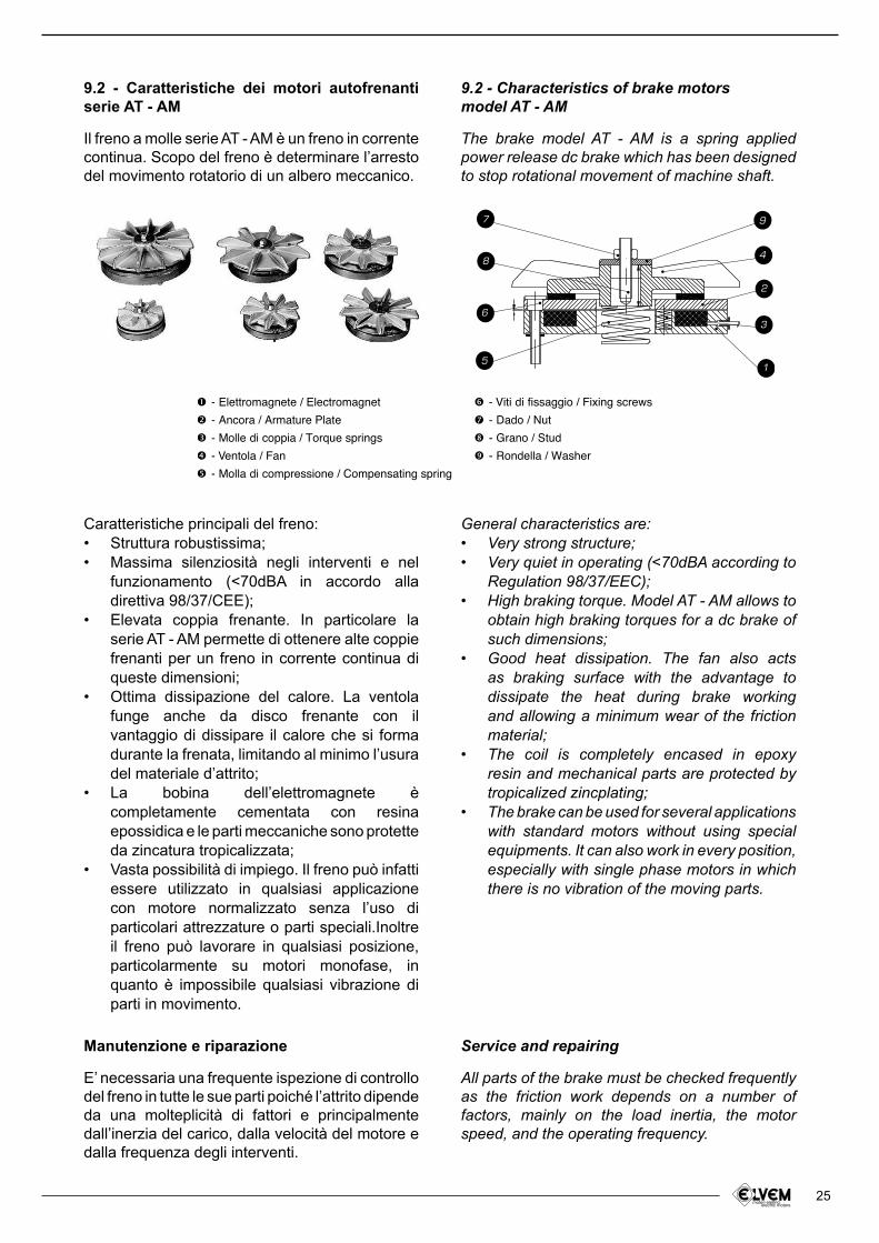
9.2 - Caratteristiche dei motori autofrenanti serie AT - AM
Il freno a molle serie AT - AM è un freno in corrente continua. Scopo del freno è determinare l’arresto del movimento rotatorio di un albero meccanico.
Manutenzione e riparazione
E’ necessaria una frequente ispezione di controllo del freno in tutte le sue parti poiché l’attrito dipende da una molteplicità di fattori e principalmente dall’inerzia del carico, dalla velocità del motore e dalla frequenza degli interventi.
9.2 - Characteristics of brake motorsmodel AT - AM
The brake model AT - AM is a spring applied power release dc brake which has been designed to stop rotational movement of machine shaft.
Service and repairing
All parts of the brake must be checked frequently as the friction work depends on a number of factors, mainly on the load inertia, the motor speed, and the operating frequency.
General characteristics are:Very strong structure;• Very quiet in operating (<70dBA according to • Regulation 98/37/EEC);High braking torque. Model AT - AM allows to • obtain high braking torques for a dc brake of such dimensions;Good heat dissipation. The fan also acts • as braking surface with the advantage to dissipate the heat during brake working and allowing a minimum wear of the friction material;The coil is completely encased in epoxy • resin and mechanical parts are protected by
tropicalized zincplating;The brake can be used for several applications • with standard motors without using special
equipments. It can also work in every position, especially with single phase motors in which
there is no vibration of the moving parts.
Caratteristiche principali del freno:Struttura robustissima;• Massima silenziosità negli interventi e nel • funzionamento (<70dBA in accordo alla direttiva 98/37/CEE);Elevata coppia frenante. In particolare la • serie AT - AM permette di ottenere alte coppie frenanti per un freno in corrente continua di queste dimensioni;Ottima dissipazione del calore. La ventola • funge anche da disco frenante con il vantaggio di dissipare il calore che si forma durante la frenata, limitando al minimo l’usura del materiale d’attrito;La bobina dell’elettromagnete è • completamente cementata con resina epossidica e le parti meccaniche sono protette da zincatura tropicalizzata;Vasta possibilità di impiego. Il freno può infatti • essere utilizzato in qualsiasi applicazione con motore normalizzato senza l’uso di particolari attrezzature o parti speciali.Inoltre il freno può lavorare in qualsiasi posizione, particolarmente su motori monofase, in quanto è impossibile qualsiasi vibrazione di parti in movimento.
97
3
1
2
5
6
48
- Elettromagnete / Electromagnet
- Ancora / Armature Plate
- Molle di coppia / Torque springs
- Ventola / Fan
- Molla di compressione / Compensating spring
- Viti di fissaggio / Fixing screws
- Dado / Nut
- Grano / Stud
- Rondella / Washer

26
E’ indispensabile sostituire l’ancora dopo un consumo del materiale d’attrito pari a 1,5 mm. Quando il traferro raggiunge un valore pari a 0,7 mm è obbligatorio riportare tale valore a 0,2 mm.Assicurarsi che dopo l’ispezione, il traferro sia correttamente regolato. Le operazioni d’ispezione devono essere eseguite a freno elettricamente scollegato e dopo avere veriicato il collegamento di messa a terra.Il buon funzionamento del freno può essere garantito solo con l’utilizzo di parti originali fornite dal costruttore. Per informazioni più dettagliate Vi preghiamo di informarci circa le speciiche condizioni di lavoro del freno.
Funzionamento
Il freno è progettato per garantire a riposo e tramite le molle di coppia, la sicurezza intrinseca pari e non superiore al suo valore di targa espresso in Nm. All’eccitazione dell’elettromagnete (1), l’ancora (2) è attratta verso lo stesso caricando le molle di coppia (3). Questo permette alla ventola (4), accoppiata all’albero meccanico tramite una chiavetta, di girare liberamente. In mancanza di corrente cessa il campo magnetico e di conseguenza le molle di coppia spingono l’ancora controla ventola, frenando così l’albero meccanico.
Regolazione del traferro
Eseguire tramite il dado (7) la regolazione del traferro fra ancora ed elettromagnete. Se l’operazione di regolazione avviene dopo un turno lavorativo assicurarsi che il corpo del freno non sia surriscaldato. Il valore massimo ammesso per il traferro è 0,7 mm. Se tale valore viene superato a causa del consumo del materiale d’attrito, le prestazioni del freno possono essere modiicate. Inoltre il superamento del valore massimo di traferro porta ad un apertura del sistema in fase di rotazione, con conseguente surriscaldamento del motore e del freno. Il superamento del valore di traferro porta ad un decadimento delle prestazioni del freno ino alla mancata funzione di frenatura.
The armature plate must be replaced after a wear of the friction material equal to 1,5 mm. When the air-gap value has achieved 0,7 mm it’s necessary to bring it back to 0,2 mm.After checking the brake make sure that the air-gap is correctly regulated.Carry out brake servicing and repariring when the brake is disconnected and after checking earthing carefully.Good working order of the brake can only be guaranteed if original components are used. For more detailed information please indicate the speciic operating conditions.
Operating
The brake is designed to assure, by means of the pressure springs and when no voltage is applied, the intrinsic safety equal to brake label value in Nm. On exciting the electromagnet the armature plate is pulled towards the electromagnet itself, thus loading the pressure springs and enabling
the fan, which is axially movable on the key-way, to turn freely. When the current fails, the pressure springs drive the armature plate towards the fan, thus braking the motor shaft.
Air gap adjustment
Make the air-gap adjustment by operating the nut (7) between the armature plate and the electromagnet. If the air-gap is made after a normal brake operation, please allow for a cooling down period. The maximum value allowed for the air-gap is 0,7 mm. If this value is exceeded the brake performances will change and this can prevent brake form braking. Incorrect maintenance of the air-gap adjustment will prevent brake to work properly during motor revolution this causing an
overheating of both the motor and the brake.
27
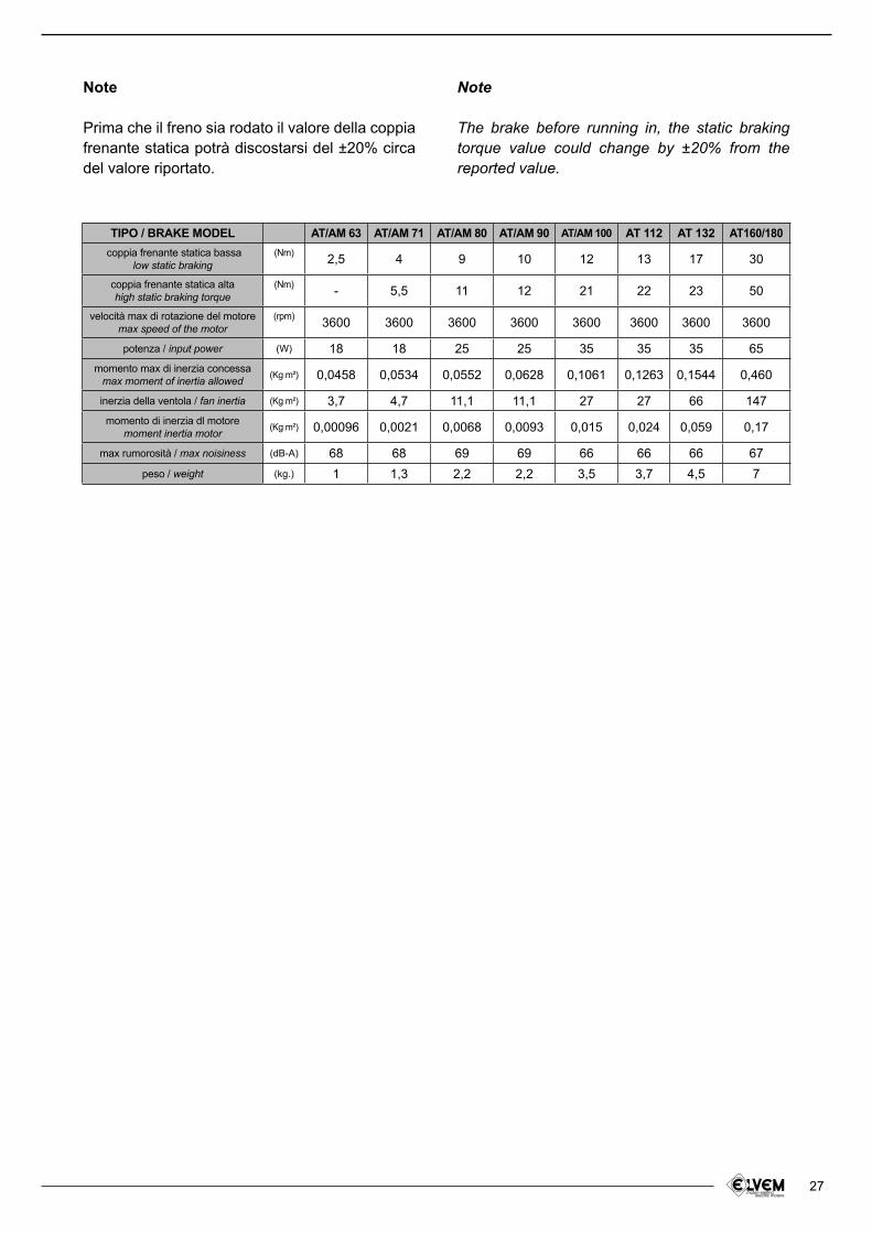
Note
Prima che il freno sia rodato il valore della coppia frenante statica potrà discostarsi del ±20% circa del valore riportato.
Note
The brake before running in, the static braking torque value could change by ±20% from the reported value.
TIPO / BRAKE MODEL AT/AM 63 AT/AM 71 AT/AM 80 AT/AM 90 AT/AM 100 AT 112 AT 132 AT160/180
coppia frenante statica bassalow static braking
(Nm)2,5 4 9 10 12 13 17 30
coppia frenante statica altahigh static braking torque
(Nm)- 5,5 11 12 21 22 23 50
velocità max di rotazione del motoremax speed of the motor
(rpm)3600 3600 3600 3600 3600 3600 3600 3600
potenza / input power (W) 18 18 25 25 35 35 35 65
momento max di inerzia concessamax moment of inertia allowed (Kg m²) 0,0458 0,0534 0,0552 0,0628 0,1061 0,1263 0,1544 0,460
inerzia della ventola / fan inertia (Kg m²) 3,7 4,7 11,1 11,1 27 27 66 147
momento di inerzia dl motoremoment inertia motor
(Kg m²) 0,00096 0,0021 0,0068 0,0093 0,015 0,024 0,059 0,17
max rumorosità / max noisiness (dB-A) 68 68 69 69 66 66 66 67
peso / weight (kg.) 1 1,3 2,2 2,2 3,5 3,7 4,5 7
28
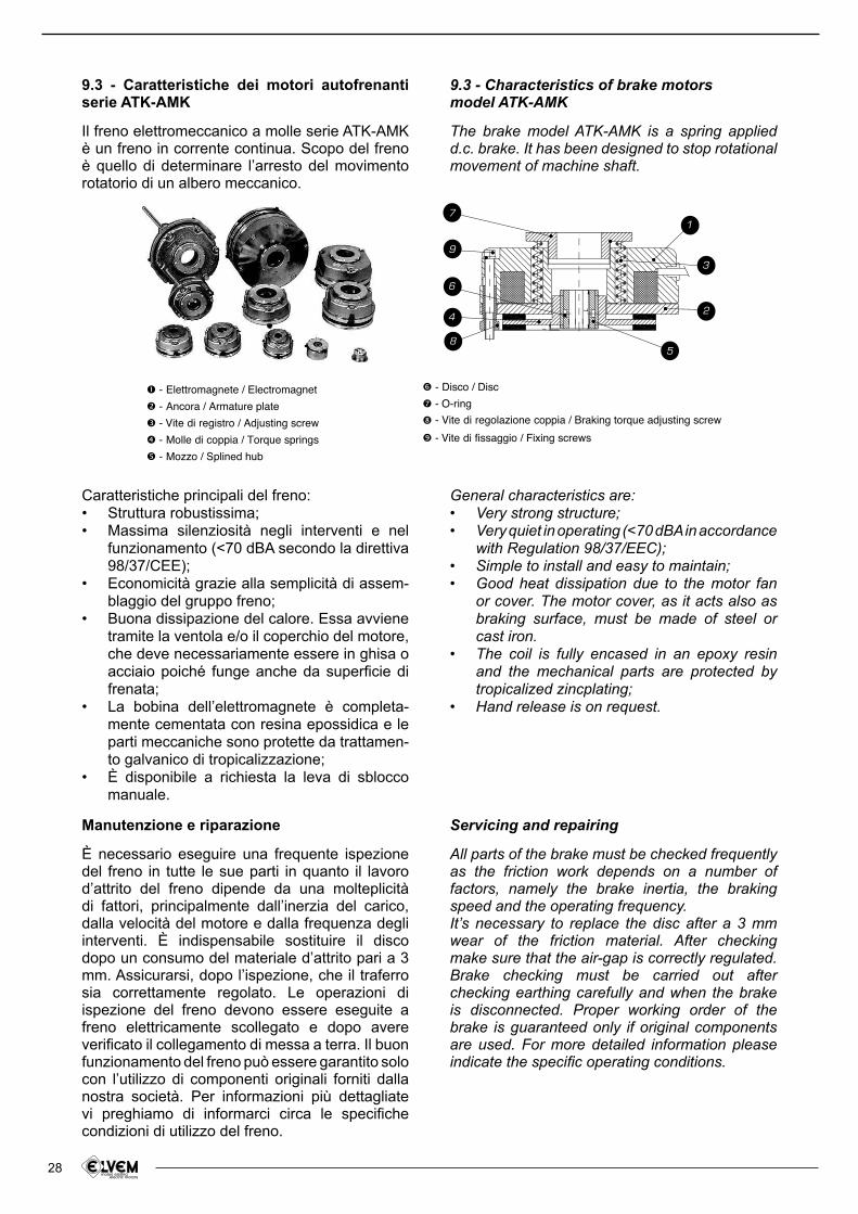
9.3 - Caratteristiche dei motori autofrenanti serie ATK-AMK
Il freno elettromeccanico a molle serie ATK-AMK è un freno in corrente continua. Scopo del freno è quello di determinare l’arresto del movimento rotatorio di un albero meccanico.
Manutenzione e riparazione
È necessario eseguire una frequente ispezione del freno in tutte le sue parti in quanto il lavoro d’attrito del freno dipende da una molteplicità di fattori, principalmente dall’inerzia del carico, dalla velocità del motore e dalla frequenza degli interventi. È indispensabile sostituire il disco dopo un consumo del materiale d’attrito pari a 3 mm. Assicurarsi, dopo l’ispezione, che il traferro sia correttamente regolato. Le operazioni di ispezione del freno devono essere eseguite a freno elettricamente scollegato e dopo avere veriicato il collegamento di messa a terra. Il buon funzionamento del freno può essere garantito solo con l’utilizzo di componenti originali forniti dalla nostra società. Per informazioni più dettagliate vi preghiamo di informarci circa le speciiche condizioni di utilizzo del freno.
Caratteristiche principali del freno:Struttura robustissima;• Massima silenziosità negli interventi e nel • funzionamento (<70 dBA secondo la direttiva 98/37/CEE);Economicità grazie alla semplicità di assem-• blaggio del gruppo freno;Buona dissipazione del calore. Essa avviene • tramite la ventola e/o il coperchio del motore, che deve necessariamente essere in ghisa o acciaio poiché funge anche da supericie di frenata;La bobina dell’elettromagnete è completa-• mente cementata con resina epossidica e le parti meccaniche sono protette da trattamen-to galvanico di tropicalizzazione;È disponibile a richiesta la leva di sblocco • manuale.
9.3 - Characteristics of brake motorsmodel ATK-AMK
The brake model ATK-AMK is a spring applied d.c. brake. It has been designed to stop rotational movement of machine shaft.
Servicing and repairing
All parts of the brake must be checked frequently as the friction work depends on a number of factors, namely the brake inertia, the braking speed and the operating frequency.It’s necessary to replace the disc after a 3 mm wear of the friction material. After checking make sure that the air-gap is correctly regulated. Brake checking must be carried out after checking earthing carefully and when the brake is disconnected. Proper working order of the brake is guaranteed only if original components are used. For more detailed information please indicate the speciic operating conditions.
General characteristics are:Very strong structure;• Very quiet in operating (<70 dBA in accordance • with Regulation 98/37/EEC);Simple to install and easy to maintain;• Good heat dissipation due to the motor fan • or cover. The motor cover, as it acts also as braking surface, must be made of steel or cast iron.The coil is fully encased in an epoxy resin • and the mechanical parts are protected by tropicalized zincplating;Hand release is on request.•
L
9
7
3
1
2
5
6
4
8
- Elettromagnete / Electromagnet
- Ancora / Armature plate
- Vite di registro / Adjusting screw
- Molle di coppia / Torque springs
- Mozzo / Splined hub
- Disco / Disc
- O-ring
- Vite di regolazione coppia / Braking torque adjusting screw
- Vite di fissaggio / Fixing screws

29
Funzionamento
Il freno è progettato per garantire a riposo e tramite le molle di coppia, la sicurezza intrinseca pari e non superiore al suo valore di targa espresso in Nm. All’eccitazione dell’elettromagnete (1), l’ancora (2) è attratta verso lo stesso caricando le molle di coppia (3). Questo permette al disco (4), accoppiato all’albero meccanico tramite un mozzo dentato (5), di girare liberamente. In mancanza di corrente cessa il campo magnetico e di conseguenza le molle di coppia spingono l’ancora contro il disco, frenando così l’albero meccanico.
Caratteristiche limitative importante!
Il corretto funzionamento del freno può essere garantito quando si opera a temperature ambiente. Nel caso il freno debba funzionare in ambienti oleosi o in ambienti con temperature estreme vi preghiamo di contattare il nostro uficio tecnico. Qualora il freno operi in ambiente esterno con condizioni di umidità e a temperature basse è indispensabile utilizzare protezioni meccaniche o di altra natura per evitare che il materiale d’attrito del disco, dopo una fase di prolungata inattività, rimanga attaccato alla supericie di frenata.
Regolazione del traferro
La regolazione del traferro avviene agendo sui registri (8), dopo aver allentato le viti di issaggio (9). Se tale operazione viene eseguita alla ine di un periodo lavorativo assicurarsi che il corpo del freno non sia surriscaldato. Il valore nominale di regolazione del traferro è 0,2 mm (+0,05 –0). Il massimo valore accettabile per il traferro è di 0,7 mm. Se tale valore viene superato a causa del consumo del materiale d’attrito, le prestazioni del freno possono essere modiicate; inoltre il superamento del valore massimo di traferro porta ad un decadimento delle prestazioni del freno, ino alla non apertura del sistema in fase di rotazione, con conseguente surriscaldamento del motore e del freno.
Regolazione della coppia frenante
Il freno ATK-AMK permette di variare la coppia frenante. In funzione del carico, della velocità di rotazione e del tempo di frenata, l’utilizzatore potrà impostare la coppia frenante più idonea alle proprie esigenze di lavoro. Se il carico di lavoro lo
Operating
The brake is designed to assure, by means of the pressure springs and when no voltage is
applied, the intrinsic safety equal and not higher than brake label value in Nm. On exciting the electromagnet (1) the armature plate (2) is pulled towards the electromagnet itself , thus loading the pressure springs (3) and enabling the disc (4), which is axially movable on the toothed hub (5), to turn freely. When the current fails, the pressure springs drive the armature plate towards the disc, thus braking the motor shaft.
Warning!
Proper working order of the brake is guaranteed when operating at room temperature. In case of greasy places or extreme temperature, please contact our technical department. When operating at low temperatures or in damp places
it’s necessary to use covers or guards to avoid the attachment of the friction material on the braking surfaces when the brake hasn’t been working for a long time.
Air-gap adjusting
Adjusting of the air-gap is made operating the adjusting screws (8) after loosening the ixing screws (9). Please allow for a cooling down period before adjusting the airgap after brake operating. The nominal value for the airgap is 0,2 mm (+0,05 –0). The maximum value allowed for the air-gap is 0,7 mm. If this value is exceeded the brake performances will change and this can prevent brake from braking. Incorrect maintenance of the air-gap adjustment will prevent brake to work properly during motor revolution this causing an
overheating of both the motor and the brake.
Braking torque adjustment
The model ATK-AMK allows the adjustment of the braking torque. The user will adjust the braking torque according to the load, the motor rotation speed and the braking time. You can adjust the braking torque, if the load allows it, under the
30
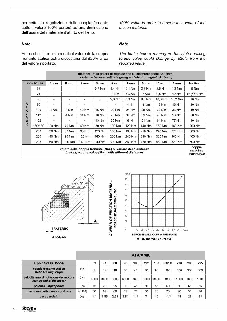
permette, la regolazione della coppia frenante sotto il valore 100% porterà ad una diminuzione dell’usura del materiale d’attrito del freno.
100% value in order to have a less wear of the friction material.
Tipo / Brake Model 63 71 80 90 100 112 132 160/180 200 200 225
coppia frenante staticastatic braking torque
(Nm)5 12 16 20 40 60 90 200 400 300 600
velocità max di rotazione del motoremax speed of the motor
(rpm)3600 3600 3600 3600 3600 3600 3600 1800 1800 1800 1800
potenza / input power (W) 15 20 25 30 45 50 55 60 60 65 65
max rumorosità / max noisiness (s dB-A) 68 69 68 69 70 70 70 70 98 98 98
peso / weight (Kg.) 1,1 1,85 2,55 2,84 4,8 7 12 14,3 18 26 28
ATK/AMK
Model 9 mm 8 mm 7 mm 6 mm 5 mm 4 mm 3 mm 2 mm 1 mm A = 0mm
63 - - - 0,7 Nm 1,4 Nm 2,1 Nm 2,8 Nm 3,5 Nm 4,3 Nm 5 Nm
71 - - - - 2 Nm 4,5 Nm 7 Nm 9,5 Nm 12 Nm 12 (14*) Nm
80 - - - - 2,6 Nm 5,3 Nm 8,0 Nm 10,6 Nm 13,2 Nm 16 Nm
90 - - - - - 4 Nm 8 Nm 12 Nm 16 Nm 20 Nm
100 4 Nm 8 Nm 12 Nm 16 Nm 20 Nm 24 Nm 28 Nm 32 Nm 36 Nm 40 Nm
112 - 4 Nm 11 Nm 18 Nm 25 Nm 32 Nm 39 Nm 46 Nm 53 Nm 60 Nm
132 - - - 13 Nm 25 Nm 38 Nm 51 Nm 64 Nm 77 Nm 90 Nm
160/180 20 Nm 40 Nm 60 Nm 80 Nm 100 Nm 120 Nm 140 Nm 160 Nm 180 Nm 200 Nm
200 30 Nm 60 Nm 90 Nm 120 Nm 150 Nm 180 Nm 210 Nm 240 Nm 270 Nm 300 Nm
200 40 Nm 80 Nm 120 Nm 160 Nm 200 Nm 240 Nm 280 Nm 320 Nm 360 Nm 400 Nm
225 60 Nm 120 Nm 160 Nm 240 Nm 300 Nm 360 Nm 420 Nm 480 Nm 520 Nm 600 Nm
Tipo /
ATK/AMK
distanza tra la ghiera di regolazione e l’elettromagnete “A” (mm.)distance between adjusting-ring and electromagnet “A” (mm.)
coppia massima
max torque
A
% W
EA
R O
F F
RIC
TIO
N M
AT
ER
IAL
PE
RC
EN
TU
AL
E C
ON
SU
MO
PERCENTUALE COPPIA FRENANTE
% BRAKING TORQUEAIR-GAP
TRAFERRO
Note
Prima che il freno sia rodato il valore della coppia frenante statica potrà discostarsi del ±20% circa dal valore riportato.
Note
The brake before running in, the static braking torque value could change by ±20% from the reported value.
valore della coppia frenante (Nm.) al variare della distanzabraking torque value (Nm.) with different distances
31
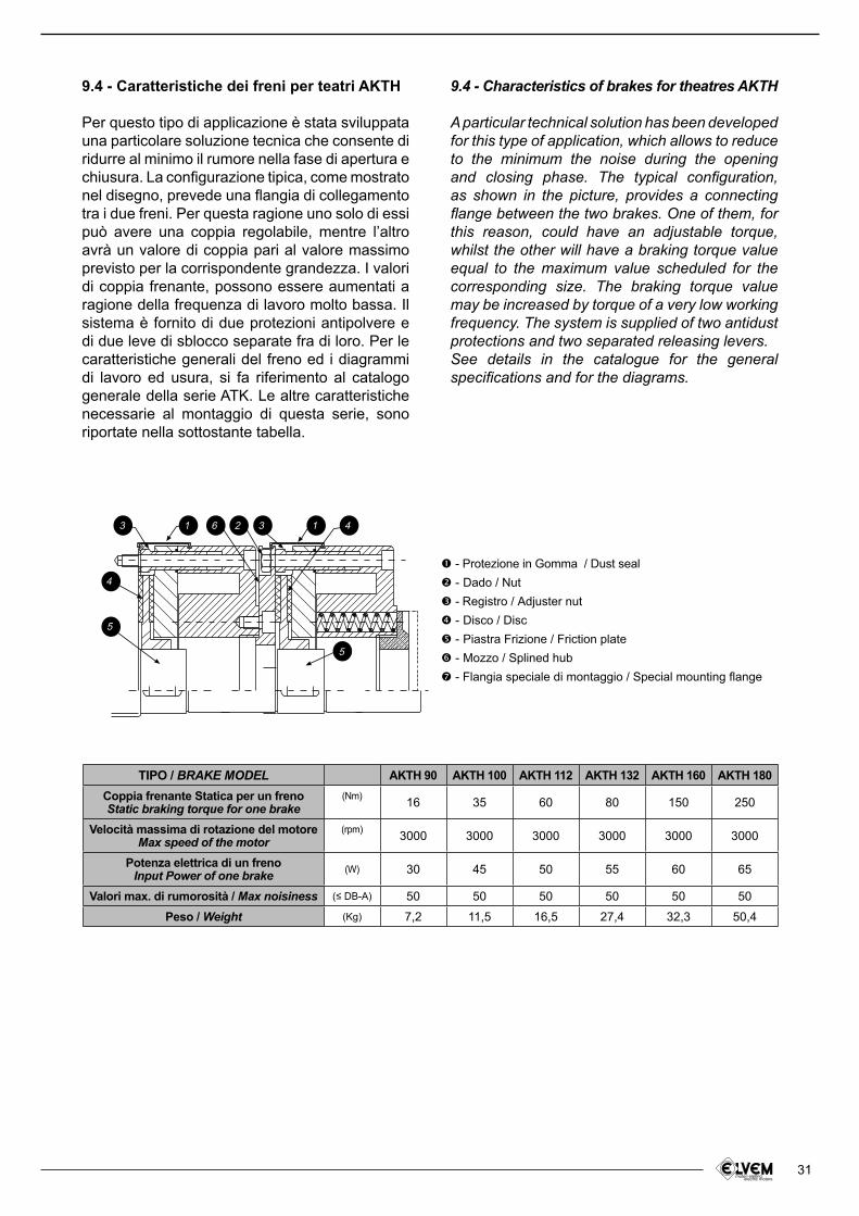
9.4 - Caratteristiche dei freni per teatri AKTH
Per questo tipo di applicazione è stata sviluppata una particolare soluzione tecnica che consente di ridurre al minimo il rumore nella fase di apertura e chiusura. La conigurazione tipica, come mostrato nel disegno, prevede una langia di collegamento tra i due freni. Per questa ragione uno solo di essi può avere una coppia regolabile, mentre l’altro avrà un valore di coppia pari al valore massimo previsto per la corrispondente grandezza. I valori di coppia frenante, possono essere aumentati a ragione della frequenza di lavoro molto bassa. Il sistema è fornito di due protezioni antipolvere e di due leve di sblocco separate fra di loro. Per le caratteristiche generali del freno ed i diagrammi di lavoro ed usura, si fa riferimento al catalogo generale della serie ATK. Le altre caratteristiche necessarie al montaggio di questa serie, sono riportate nella sottostante tabella.
9.4 - Characteristics of brakes for theatres AKTH
A particular technical solution has been developed for this type of application, which allows to reduce to the minimum the noise during the opening and closing phase. The typical coniguration, as shown in the picture, provides a connecting lange between the two brakes. One of them, for this reason, could have an adjustable torque, whilst the other will have a braking torque value equal to the maximum value scheduled for the corresponding size. The braking torque value may be increased by torque of a very low working frequency. The system is supplied of two antidust protections and two separated releasing levers.See details in the catalogue for the general speciications and for the diagrams.
5
5
4
3 1 6 2 3 1 4
- Protezione in Gomma / Dust seal
- Dado / Nut
- Registro / Adjuster nut
- Disco / Disc
- Piastra Frizione / Friction plate
- Mozzo / Splined hub
- Flangia speciale di montaggio / Special mounting flange
TIPO / BRAKE MODEL AKTH 90 AKTH 100 AKTH 112 AKTH 132 AKTH 160 AKTH 180
Coppia frenante Statica per un frenoStatic braking torque for one brake
(Nm)16 35 60 80 150 250
Velocità massima di rotazione del motoreMax speed of the motor
(rpm)3000 3000 3000 3000 3000 3000
Potenza elettrica di un frenoInput Power of one brake (W) 30 45 50 55 60 65
Valori max. di rumorosità / Max noisiness (≤ DB-A) 50 50 50 50 50 50
Peso / Weight (Kg) 7,2 11,5 16,5 27,4 32,3 50,4
32
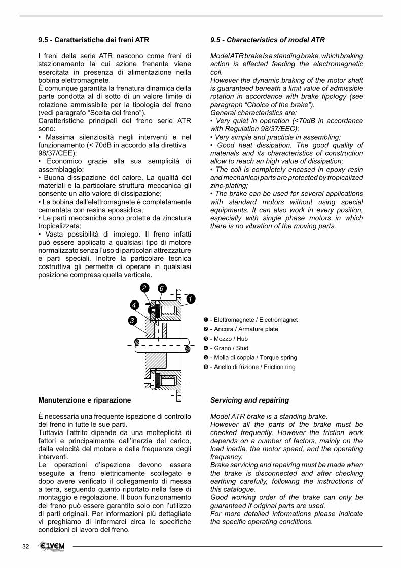
- Elettromagnete / Electromagnet
- Ancora / Armature plate
- Mozzo / Hub
- Grano / Stud
- Molla di coppia / Torque spring
- Anello di frizione / Friction ring
1
62
4
3
9.5 - Caratteristiche dei freni ATR
I freni della serie ATR nascono come freni di stazionamento la cui azione frenante viene esercitata in presenza di alimentazione nella bobina elettromagnete.È comunque garantita la frenatura dinamica della parte condotta al di sotto di un valore limite di rotazione ammissibile per la tipologia del freno (vedi paragrafo “Scelta del freno”).Caratteristiche principali del freno serie ATR sono:• Massima silenziosità negli interventi e nel funzionamento (< 70dB in accordo alla direttiva98/37/CEE);• Economico grazie alla sua semplicità di assemblaggio;• Buona dissipazione del calore. La qualità dei materiali e la particolare struttura meccanica gli consente un alto valore di dissipazione;• La bobina dell’elettromagnete è completamente cementata con resina epossidica;• Le parti meccaniche sono protette da zincatura tropicalizzata;• Vasta possibilità di impiego. Il freno infatti può essere applicato a qualsiasi tipo di motore normalizzato senza l’uso di particolari attrezzature e parti speciali. Inoltre la particolare tecnica costruttiva gli permette di operare in qualsiasi posizione compresa quella verticale.
9.5 - Characteristics of model ATR
Model ATR brake is a standing brake, which braking action is effected feeding the electromagnetic coil.However the dynamic braking of the motor shaft is guaranteed beneath a limit value of admissible rotation in accordance with brake tipology (see paragraph “Choice of the brake”).General characteristics are:• Very quiet in operation (<70dB in accordance with Regulation 98/37/EEC);• Very simple and practicle in assembling;• Good heat dissipation. The good quality of materials and its characteristics of construction allow to reach an high value of dissipation;• The coil is completely encased in epoxy resin and mechanical parts are protected by tropicalized zinc-plating;• The brake can be used for several applications with standard motors without using special equipments. It can also work in every position, especially with single phase motors in which there is no vibration of the moving parts.
Manutenzione e riparazione
È necessaria una frequente ispezione di controllo del freno in tutte le sue parti.Tuttavia l’attrito dipende da una molteplicità di fattori e principalmente dall’inerzia del carico, dalla velocità del motore e dalla frequenza degli interventi.Le operazioni d’ispezione devono essere eseguite a freno elettricamente scollegato e dopo avere veriicato il collegamento di messa a terra, seguendo quanto riportato nella fase di montaggio e regolazione. Il buon funzionamento del freno può essere garantito solo con l’utilizzo di parti originali. Per informazioni più dettagliate vi preghiamo di informarci circa le speciiche condizioni di lavoro del freno.
Servicing and repairing
Model ATR brake is a standing brake.However all the parts of the brake must be checked frequently. However the friction work depends on a number of factors, mainly on the load inertia, the motor speed, and the operating frequency.Brake servicing and repairing must be made when the brake is disconnected and after checking earthing carefully, following the instructions of this catalogue.Good working order of the brake can only be guaranteed if original parts are used.For more detailed informations please indicate the speciic operating conditions.
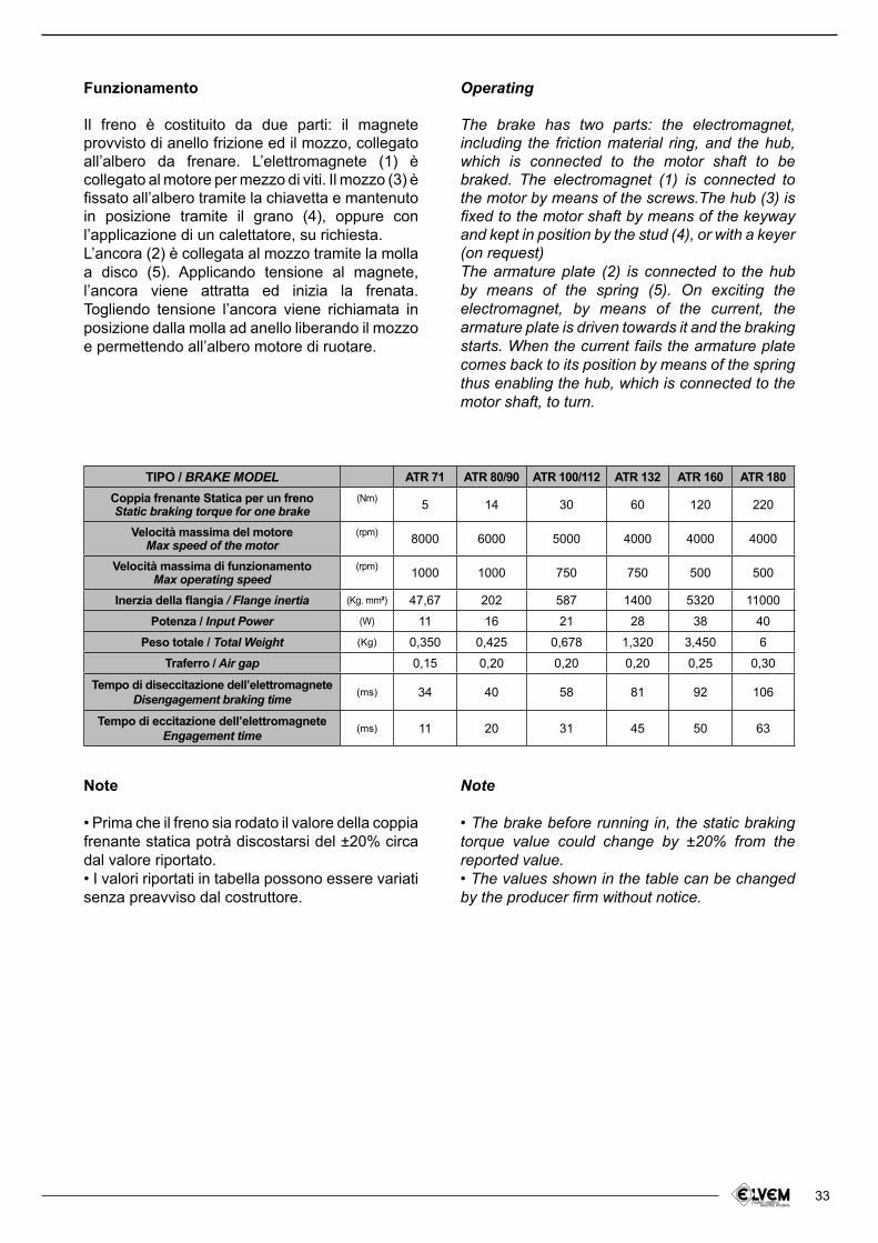
33
Funzionamento
Il freno è costituito da due parti: il magnete provvisto di anello frizione ed il mozzo, collegato all’albero da frenare. L’elettromagnete (1) è collegato al motore per mezzo di viti. Il mozzo (3) è issato all’albero tramite la chiavetta e mantenuto in posizione tramite il grano (4), oppure con l’applicazione di un calettatore, su richiesta. L’ancora (2) è collegata al mozzo tramite la molla a disco (5). Applicando tensione al magnete, l’ancora viene attratta ed inizia la frenata. Togliendo tensione l’ancora viene richiamata in posizione dalla molla ad anello liberando il mozzo e permettendo all’albero motore di ruotare.
Operating
The brake has two parts: the electromagnet, including the friction material ring, and the hub, which is connected to the motor shaft to be braked. The electromagnet (1) is connected to the motor by means of the screws.The hub (3) is ixed to the motor shaft by means of the keyway and kept in position by the stud (4), or with a keyer (on request) The armature plate (2) is connected to the hub by means of the spring (5). On exciting the electromagnet, by means of the current, the armature plate is driven towards it and the braking starts. When the current fails the armature plate comes back to its position by means of the spring thus enabling the hub, which is connected to the motor shaft, to turn.
Note
• Prima che il freno sia rodato il valore della coppia frenante statica potrà discostarsi del ±20% circa dal valore riportato.• I valori riportati in tabella possono essere variati senza preavviso dal costruttore.
Note
• The brake before running in, the static braking torque value could change by ±20% from the reported value.• The values shown in the table can be changed by the producer irm without notice.
TIPO / BRAKE MODEL ATR 71 ATR 80/90 ATR 100/112 ATR 132 ATR 160 ATR 180
Coppia frenante Statica per un frenoStatic braking torque for one brake
(Nm)5 14 30 60 120 220
Velocità massima del motoreMax speed of the motor
(rpm)8000 6000 5000 4000 4000 4000
Velocità massima di funzionamentoMax operating speed
(rpm)1000 1000 750 750 500 500
Inerzia della langia / Flange inertia (Kg. mm²) 47,67 202 587 1400 5320 11000
Potenza / Input Power (W) 11 16 21 28 38 40
Peso totale / Total Weight (Kg) 0,350 0,425 0,678 1,320 3,450 6
Traferro / Air gap 0,15 0,20 0,20 0,20 0,25 0,30
Tempo di diseccitazione dell’elettromagnete Disengagement braking time (ms) 34 40 58 81 92 106
Tempo di eccitazione dell’elettromagneteEngagement time (ms) 11 20 31 45 50 63
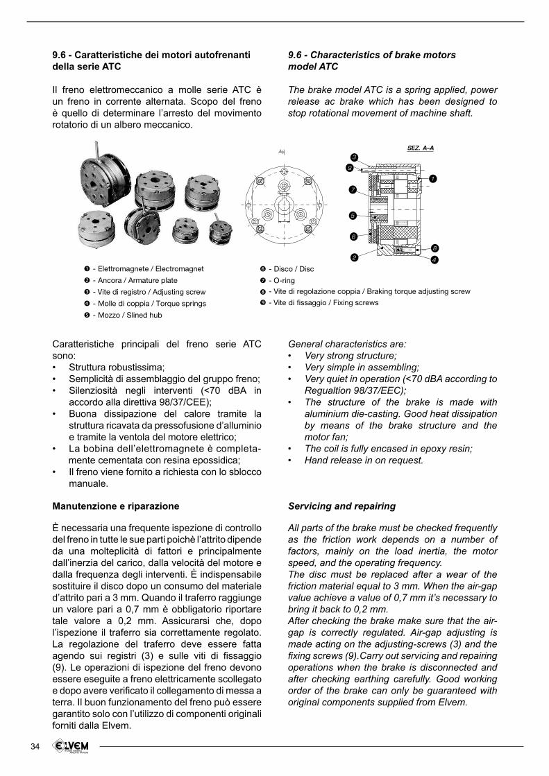
34
9.6 - Caratteristiche dei motori autofrenantidella serie ATC
Il freno elettromeccanico a molle serie ATC è un freno in corrente alternata. Scopo del freno è quello di determinare l’arresto del movimento rotatorio di un albero meccanico.
9.6 - Characteristics of brake motorsmodel ATC
The brake model ATC is a spring applied, power release ac brake which has been designed to stop rotational movement of machine shaft.
Manutenzione e riparazione
È necessaria una frequente ispezione di controllo del freno in tutte le sue parti poichè l’attrito dipende da una molteplicità di fattori e principalmente dall’inerzia del carico, dalla velocità del motore e dalla frequenza degli interventi. È indispensabile sostituire il disco dopo un consumo del materiale d’attrito pari a 3 mm. Quando il traferro raggiunge un valore pari a 0,7 mm è obbligatorio riportare tale valore a 0,2 mm. Assicurarsi che, dopo l’ispezione il traferro sia correttamente regolato. La regolazione del traferro deve essere fatta agendo sui registri (3) e sulle viti di issaggio (9). Le operazioni di ispezione del freno devono essere eseguite a freno elettricamente scollegato e dopo avere veriicato il collegamento di messa a terra. Il buon funzionamento del freno può essere garantito solo con l’utilizzo di componenti originali forniti dalla Elvem.
Servicing and repairing
All parts of the brake must be checked frequently as the friction work depends on a number of factors, mainly on the load inertia, the motor speed, and the operating frequency.The disc must be replaced after a wear of the friction material equal to 3 mm. When the air-gap value achieve a value of 0,7 mm it’s necessary to bring it back to 0,2 mm.After checking the brake make sure that the air-gap is correctly regulated. Air-gap adjusting is made acting on the adjusting-screws (3) and the ixing screws (9).Carry out servicing and repairing operations when the brake is disconnected and after checking earthing carefully. Good working order of the brake can only be guaranteed with original components supplied from Elvem.
General characteristics are:Very strong structure;• Very simple in assembling;• Very quiet in operation (<70 dBA according to • Regualtion 98/37/EEC);The structure of the brake is made with • aluminium die-casting. Good heat dissipation by means of the brake structure and the motor fan;The coil is fully encased in epoxy resin;• Hand release in on request.•
Caratteristiche principali del freno serie ATC sono:
Struttura robustissima;• Semplicità di assemblaggio del gruppo freno;• Silenziosità negli interventi (<70 dBA in • accordo alla direttiva 98/37/CEE);Buona dissipazione del calore tramite la • struttura ricavata da pressofusione d’alluminio e tramite la ventola del motore elettrico;La bobina dell’elettromagnete è completa-•
mente cementata con resina epossidica;Il freno viene fornito a richiesta con lo sblocco • manuale.
1
2
5
6
4
8
9
7
3
R
F
ASEZ. A–A
- Elettromagnete / Electromagnet
- Ancora / Armature plate
- Vite di registro / Adjusting screw
- Molle di coppia / Torque springs
- Mozzo / Slined hub
- Disco / Disc
- O-ring
- Vite di regolazione coppia / Braking torque adjusting screw
- Vite di fissaggio / Fixing screws
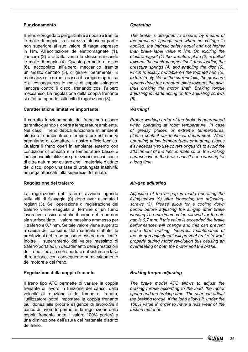
35
Funzionamento
Il freno è progettato per garantire a riposo e tramite le molle di coppia, la sicurezza intrinseca pari e non superiore al suo valore di targa espresso in Nm. All’eccitazione dell’elettromagnete (1), l’ancora (2) è attratta verso lo stesso caricando le molle di coppia (4). Questo permette al disco (6), accoppiato all’albero meccanico tramite un mozzo dentato (5), di girare liberamente. In mancanza di corrente cessa il campo magnetico e di conseguenza le molle di coppia spingono l’ancora contro il disco, frenando così l’albero meccanico. La regolazione della coppia frenante si effettua agendo sulle viti di regolazione (8).
Caratteristiche limitative importante!
Il corretto funzionamento del freno può essere garantito quando si opera a temperature ambiente. Nel caso il freno debba funzionare in ambienti oleosi o in ambienti con temperature estreme vi preghiamo di contattare il nostro uficio tecnico. Qualora il freno operi in ambiente esterno con condizioni di umidità e a temperature basse è indispensabile utilizzare protezioni meccaniche o di altra natura per evitare che il materiale d’attrito del disco, dopo una fase di prolungata inattività, rimanga attaccato alla supericie di frenata.
Regolazione del traferro
La regolazione del traferro avviene agendo sulle viti di issaggio (9) dopo aver allentato I registri (3). Se l’operazione di registrazione del traferro viene eseguita al termine di un turno lavorativo, assicurarsi che il corpo del freno non sia surriscaldato. Il valore massimo ammesso per il traferro è 0,7 mm. Se tale valore viene superato a causa del consumo del materiale d’attrito, le prestazioni del freno possono essere modiicate.Inoltre il superamento del valore massimo di traferro porta ad un decadimento delle prestazioni del freno, ino alla non apertura del sistema in fase di rotazione, con conseguente surriscaldamento del motore e del freno.
Regolazione della coppia frenante
Il freno tipo ATC permette di variare la coppia frenante di lavoro in funzione del carico, della velocità di rotazione e del tempo di frenata, l’utilizzatore potrà impostare la coppia frenante più idonea alle proprie esigenze di lavoro.Se il carico di lavoro lo permette, la regolazione della coppia frenante sotto il valore 100% porterà a una diminuzione dell’usura del materiale d’attrito del freno.
Operating
The brake is designed to assure, by means of the pressure springs and when no voltage is applied, the intrinsic safety equal and not higher than brake label value in Nm. On exciting the electromagnet (1) the armature plate (2) is pulled towards the electromagnet itself, thus loading the pressure springs (4) and enabling the disc (6), which is axially movable on the toothed hub (5), to turn freely. When the current fails, the pressure springs drive the armature plate towards the disc, thus braking the motor shaft. Braking torque adjusting is made acting on the adjusting screws (8).
Warning!
Proper working order of the brake is guaranteed when operating at room temperature. In case of greasy places or extreme temperatures, please contact our technical department. When operating at low temperatures or in damp places it’s necessary to use covers or guards to avoid the attachment of the friction material on the braking surfaces when the brake hasn’t been working for a long time.
Air-gap adjusting
Adjusting of the air-gap is made operating the ixingscrews (9) after loosening the adjusting-screws (3). Please allow for a cooling down period before adjusting the air-gap after brake working.The maximum value allowed for the air-gap is 0,7 mm. If this value is exceeded the brake performances will change and this can prevent brake form braking. Incorrect maintenance of the air-gap adjustment will prevent brake to work properly during motor revolution this causing an overheating of both the motor and the brake.
Braking torque adjusting
The brake model ATC allows to adjust the braking torque according to the load, the motor speed and the braking time. The user can adjust the braking torque, if the load allows it, under the 100% value in order to have a less wear of the friction material.
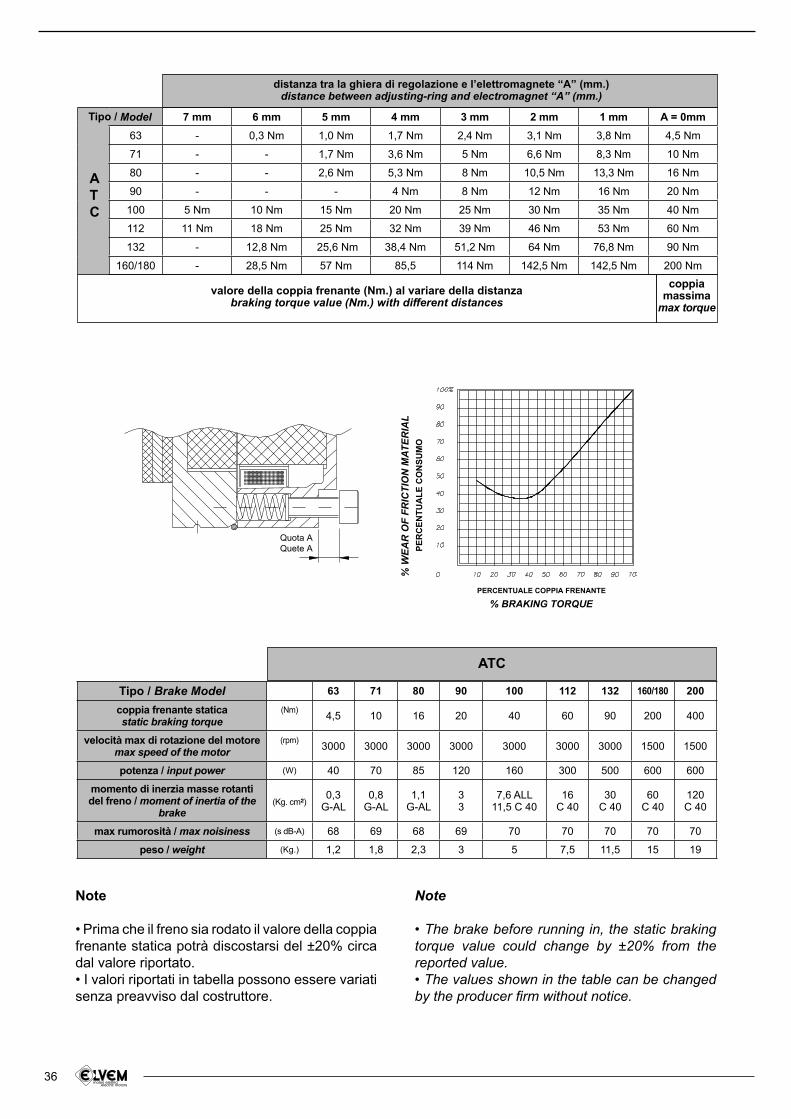
36
Tipo / Brake Model 63 71 80 90 100 112 132 160/180 200
coppia frenante staticastatic braking torque
(Nm)4,5 10 16 20 40 60 90 200 400
velocità max di rotazione del motoremax speed of the motor
(rpm)3000 3000 3000 3000 3000 3000 3000 1500 1500
potenza / input power (W) 40 70 85 120 160 300 500 600 600
momento di inerzia masse rotanti del freno / moment of inertia of the
brake
(Kg. cm²)0,3
G-AL0,8
G-AL1,1
G-AL33
7,6 ALL11,5 C 40
16C 40
30C 40
60C 40
120C 40
max rumorosità / max noisiness (s dB-A) 68 69 68 69 70 70 70 70 70
peso / weight (Kg.) 1,2 1,8 2,3 3 5 7,5 11,5 15 19
ATC
Model 7 mm 6 mm 5 mm 4 mm 3 mm 2 mm 1 mm A = 0mm
63 - 0,3 Nm 1,0 Nm 1,7 Nm 2,4 Nm 3,1 Nm 3,8 Nm 4,5 Nm
71 - - 1,7 Nm 3,6 Nm 5 Nm 6,6 Nm 8,3 Nm 10 Nm
80 - - 2,6 Nm 5,3 Nm 8 Nm 10,5 Nm 13,3 Nm 16 Nm
90 - - - 4 Nm 8 Nm 12 Nm 16 Nm 20 Nm
100 5 Nm 10 Nm 15 Nm 20 Nm 25 Nm 30 Nm 35 Nm 40 Nm
112 11 Nm 18 Nm 25 Nm 32 Nm 39 Nm 46 Nm 53 Nm 60 Nm
132 - 12,8 Nm 25,6 Nm 38,4 Nm 51,2 Nm 64 Nm 76,8 Nm 90 Nm
160/180 - 28,5 Nm 57 Nm 85,5 114 Nm 142,5 Nm 142,5 Nm 200 Nm
Tipo /
A T C
distanza tra la ghiera di regolazione e l’elettromagnete “A” (mm.)distance between adjusting-ring and electromagnet “A” (mm.)
coppia massima
max torque
% W
EA
R O
F F
RIC
TIO
N M
AT
ER
IAL
PE
RC
EN
TU
AL
E C
ON
SU
MO
PERCENTUALE COPPIA FRENANTE
Quota A
Quete A
% BRAKING TORQUE
Note
• Prima che il freno sia rodato il valore della coppia frenante statica potrà discostarsi del ±20% circa dal valore riportato.• I valori riportati in tabella possono essere variati senza preavviso dal costruttore.
Note
• The brake before running in, the static braking torque value could change by ±20% from the reported value.• The values shown in the table can be changed by the producer irm without notice.
valore della coppia frenante (Nm.) al variare della distanzabraking torque value (Nm.) with different distances
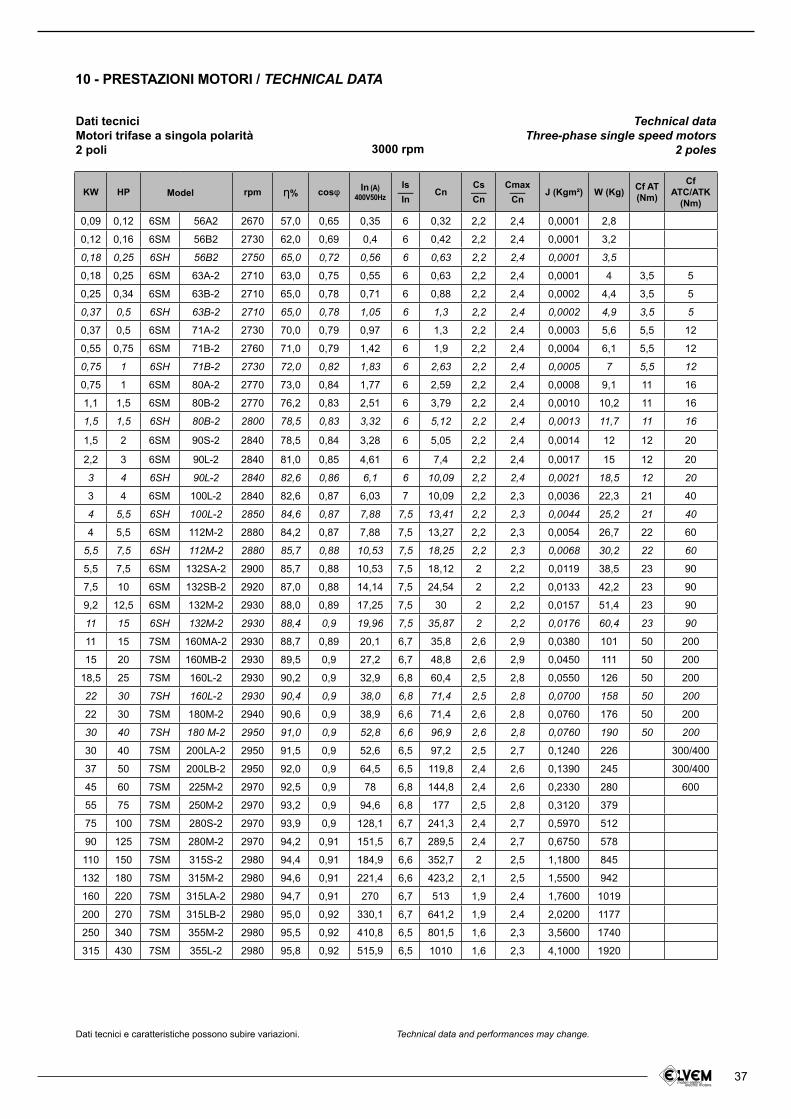
37
KW HP rpm さ% cosl In (A)400V50Hz
Is___In
CnCs___Cn
Cmax___Cn
J (Kgm²) W (Kg)Cf AT(Nm)
CfATC/ATK
(Nm)
0,09 0,12 6SM 56A2 2670 57,0 0,65 0,35 6 0,32 2,2 2,4 0,0001 2,8
0,12 0,16 6SM 56B2 2730 62,0 0,69 0,4 6 0,42 2,2 2,4 0,0001 3,2
0,18 0,25 6SH 56B2 2750 65,0 0,72 0,56 6 0,63 2,2 2,4 0,0001 3,5
0,18 0,25 6SM 63A-2 2710 63,0 0,75 0,55 6 0,63 2,2 2,4 0,0001 4 3,5 5
0,25 0,34 6SM 63B-2 2710 65,0 0,78 0,71 6 0,88 2,2 2,4 0,0002 4,4 3,5 5
0,37 0,5 6SH 63B-2 2710 65,0 0,78 1,05 6 1,3 2,2 2,4 0,0002 4,9 3,5 5
0,37 0,5 6SM 71A-2 2730 70,0 0,79 0,97 6 1,3 2,2 2,4 0,0003 5,6 5,5 12
0,55 0,75 6SM 71B-2 2760 71,0 0,79 1,42 6 1,9 2,2 2,4 0,0004 6,1 5,5 12
0,75 1 6SH 71B-2 2730 72,0 0,82 1,83 6 2,63 2,2 2,4 0,0005 7 5,5 12
0,75 1 6SM 80A-2 2770 73,0 0,84 1,77 6 2,59 2,2 2,4 0,0008 9,1 11 16
1,1 1,5 6SM 80B-2 2770 76,2 0,83 2,51 6 3,79 2,2 2,4 0,0010 10,2 11 16
1,5 1,5 6SH 80B-2 2800 78,5 0,83 3,32 6 5,12 2,2 2,4 0,0013 11,7 11 16
1,5 2 6SM 90S-2 2840 78,5 0,84 3,28 6 5,05 2,2 2,4 0,0014 12 12 20
2,2 3 6SM 90L-2 2840 81,0 0,85 4,61 6 7,4 2,2 2,4 0,0017 15 12 20
3 4 6SH 90L-2 2840 82,6 0,86 6,1 6 10,09 2,2 2,4 0,0021 18,5 12 20
3 4 6SM 100L-2 2840 82,6 0,87 6,03 7 10,09 2,2 2,3 0,0036 22,3 21 40
4 5,5 6SH 100L-2 2850 84,6 0,87 7,88 7,5 13,41 2,2 2,3 0,0044 25,2 21 40
4 5,5 6SM 112M-2 2880 84,2 0,87 7,88 7,5 13,27 2,2 2,3 0,0054 26,7 22 60
5,5 7,5 6SH 112M-2 2880 85,7 0,88 10,53 7,5 18,25 2,2 2,3 0,0068 30,2 22 60
5,5 7,5 6SM 132SA-2 2900 85,7 0,88 10,53 7,5 18,12 2 2,2 0,0119 38,5 23 90
7,5 10 6SM 132SB-2 2920 87,0 0,88 14,14 7,5 24,54 2 2,2 0,0133 42,2 23 90
9,2 12,5 6SM 132M-2 2930 88,0 0,89 17,25 7,5 30 2 2,2 0,0157 51,4 23 90
11 15 6SH 132M-2 2930 88,4 0,9 19,96 7,5 35,87 2 2,2 0,0176 60,4 23 90
11 15 7SM 160MA-2 2930 88,7 0,89 20,1 6,7 35,8 2,6 2,9 0,0380 101 50 200
15 20 7SM 160MB-2 2930 89,5 0,9 27,2 6,7 48,8 2,6 2,9 0,0450 111 50 200
18,5 25 7SM 160L-2 2930 90,2 0,9 32,9 6,8 60,4 2,5 2,8 0,0550 126 50 200
22 30 7SH 160L-2 2930 90,4 0,9 38,0 6,8 71,4 2,5 2,8 0,0700 158 50 200
22 30 7SM 180M-2 2940 90,6 0,9 38,9 6,6 71,4 2,6 2,8 0,0760 176 50 200
30 40 7SH 180 M-2 2950 91,0 0,9 52,8 6,6 96,9 2,6 2,8 0,0760 190 50 200
30 40 7SM 200LA-2 2950 91,5 0,9 52,6 6,5 97,2 2,5 2,7 0,1240 226 300/400
37 50 7SM 200LB-2 2950 92,0 0,9 64,5 6,5 119,8 2,4 2,6 0,1390 245 300/400
45 60 7SM 225M-2 2970 92,5 0,9 78 6,8 144,8 2,4 2,6 0,2330 280 600
55 75 7SM 250M-2 2970 93,2 0,9 94,6 6,8 177 2,5 2,8 0,3120 379
75 100 7SM 280S-2 2970 93,9 0,9 128,1 6,7 241,3 2,4 2,7 0,5970 512
90 125 7SM 280M-2 2970 94,2 0,91 151,5 6,7 289,5 2,4 2,7 0,6750 578
110 150 7SM 315S-2 2980 94,4 0,91 184,9 6,6 352,7 2 2,5 1,1800 845
132 180 7SM 315M-2 2980 94,6 0,91 221,4 6,6 423,2 2,1 2,5 1,5500 942
160 220 7SM 315LA-2 2980 94,7 0,91 270 6,7 513 1,9 2,4 1,7600 1019
200 270 7SM 315LB-2 2980 95,0 0,92 330,1 6,7 641,2 1,9 2,4 2,0200 1177
250 340 7SM 355M-2 2980 95,5 0,92 410,8 6,5 801,5 1,6 2,3 3,5600 1740
315 430 7SM 355L-2 2980 95,8 0,92 515,9 6,5 1010 1,6 2,3 4,1000 1920
Model
Dati tecniciMotori trifase a singola polarità2 poli
Dati tecnici e caratteristiche possono subire variazioni. Technical data and performances may change.
Technical dataThree-phase single speed motors
2 poles3000 rpm
10 - PRESTAZIONI MOTORI / TECHNICAL DATA
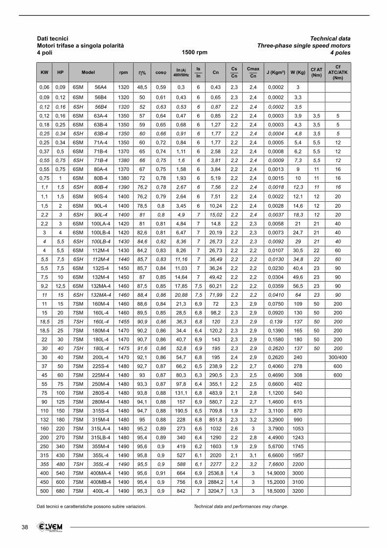
38
KW HP rpm さ% cosl In (A)400V50Hz
Is___In
CnCs___Cn
Cmax___Cn
J (Kgm²) W (Kg)Cf AT(Nm)
CfATC/ATK
(Nm)
0,06 0,09 6SM 56A4 1320 48,5 0,59 0,3 6 0,43 2,3 2,4 0,0002 3
0,09 0,12 6SM 56B4 1320 50 0,61 0,43 6 0,65 2,3 2,4 0,0002 3,3
0,12 0,16 6SH 56B4 1320 52 0,63 0,53 6 0,87 2,2 2,4 0,0002 3,5
0,12 0,16 6SM 63A-4 1350 57 0,64 0,47 6 0,85 2,2 2,4 0,0003 3,9 3,5 5
0,18 0,25 6SM 63B-4 1350 59 0,65 0,68 6 1,27 2,2 2,4 0,0003 4,3 3,5 5
0,25 0,34 6SH 63B-4 1350 60 0,66 0,91 6 1,77 2,2 2,4 0,0004 4,8 3,5 5
0,25 0,34 6SM 71A-4 1350 60 0,72 0,84 6 1,77 2,2 2,4 0,0005 5,4 5,5 12
0,37 0,5 6SM 71B-4 1370 65 0,74 1,11 6 2,58 2,2 2,4 0,0008 6,2 5,5 12
0,55 0,75 6SH 71B-4 1380 66 0,75 1,6 6 3,81 2,2 2,4 0,0009 7,3 5,5 12
0,55 0,75 6SM 80A-4 1370 67 0,75 1,58 6 3,84 2,2 2,4 0,0013 9 11 16
0,75 1 6SM 80B-4 1380 72 0,78 1,93 6 5,19 2,2 2,4 0,0015 10 11 16
1,1 1,5 6SH 80B-4 1390 76,2 0,78 2,67 6 7,56 2,2 2,4 0,0018 12,3 11 16
1,1 1,5 6SM 90S-4 1400 76,2 0,79 2,64 6 7,51 2,2 2,4 0,0022 12,1 12 20
1,5 2 6SM 90L-4 1400 78,5 0,8 3,45 6 10,24 2,2 2,4 0,0028 14,6 12 20
2,2 3 6SH 90L-4 1400 81 0,8 4,9 7 15,02 2,2 2,4 0,0037 18,3 12 20
2,2 3 6SM 100LA-4 1420 81 0,81 4,84 7 14,8 2,2 2,3 0,0058 21 21 40
3 4 6SM 100LB-4 1420 82,6 0,81 6,47 7 20,19 2,2 2,3 0,0073 24,7 21 40
4 5,5 6SH 100LB-4 1430 84,6 0,82 8,36 7 26,73 2,2 2,3 0,0092 29 21 40
4 5,5 6SM 112M-4 1430 84,2 0,83 8,26 7 26,73 2,2 2,2 0,0107 30,5 22 60
5,5 7,5 6SH 112M-4 1440 85,7 0,83 11,16 7 36,49 2,2 2,2 0,0130 34,8 22 60
5,5 7,5 6SM 132S-4 1450 85,7 0,84 11,03 7 36,24 2,2 2,2 0,0230 40,4 23 90
7,5 10 6SM 132M-4 1450 87 0,85 14,64 7 49,42 2,2 2,2 0,0304 49,6 23 90
9,2 12,5 6SM 132MA-4 1460 87,5 0,85 17,85 7,5 60,21 2,2 2,2 0,0359 56,5 23 90
11 15 6SH 132MA-4 1460 88,4 0,86 20,88 7,5 71,99 2,2 2,2 0,0410 64 23 90
11 15 7SM 160M-4 1460 88,6 0,84 21,3 6,9 72 2,3 2,9 0,0750 109 50 200
15 20 7SM 160L-4 1460 89,5 0,85 28,5 6,8 98,2 2,3 2,9 0,0920 130 50 200
18,5 25 7SH 160L-4 1455 90,9 0,86 36,3 6,8 120 2,3 2,9 0,139 137 50 200
18,5 25 7SM 180M-4 1470 90,2 0,86 34,4 6,4 120,2 2,3 2,9 0,1390 165 50 200
22 30 7SM 180L-4 1470 90,7 0,86 40,7 6,9 143 2,3 2,9 0,1580 180 50 200
30 40 7SH 180L-4 1475 91,6 0,86 52,8 6,9 195 2,3 2,9 0,2620 137 50 200
30 40 7SM 200L-4 1470 92,1 0,86 54,7 6,8 195 2,4 2,9 0,2620 240 300/400
37 50 7SM 225S-4 1480 92,7 0,87 66,2 6,5 238,9 2,2 2,7 0,4060 278 600
45 60 7SM 225M-4 1480 93 0,87 80,3 6,3 290,5 2,3 2,5 0,4690 308 600
55 75 7SM 250M-4 1480 93,3 0,87 97,8 6,4 355,1 2,2 2,5 0,6600 402
75 100 7SM 280S-4 1480 93,8 0,88 131,1 6,8 483,9 2,1 2,8 1,1200 540
90 125 7SM 280M-4 1480 94,1 0,88 157 6,9 580,7 2,2 2,7 1,4600 615
110 150 7SM 315S-4 1480 94,7 0,88 190,5 6,5 709,8 1,9 2,7 3,1100 870
132 180 7SM 315M-4 1480 95 0,88 228 6,8 851,8 2,3 3,2 3,2900 990
160 220 7SM 315LA-4 1480 95,2 0,89 273 6,6 1032 2,6 3 3,7900 1053
200 270 7SM 315LB-4 1480 95,4 0,89 340 6,4 1290 2,2 2,8 4,4900 1243
250 340 7SM 355M-4 1490 95,6 0,9 419 6,2 1603 1,9 2,9 5,6700 1745
315 430 7SM 355L-4 1490 95,8 0,9 527 6,1 2020 2,1 3,1 6,6600 1957
355 480 7SH 355L-4 1490 95,5 0,9 588 6,1 2277 2,2 3,2 7,6600 2200
400 540 7SM 400MA-4 1490 95,6 0,91 664 6,9 2536,8 1,4 3 14,9000 3000
450 600 7SM 400MB-4 1490 95,4 0,9 756 6,9 2884,2 1,4 3 15,2000 3100
500 680 7SM 400L-4 1490 95,3 0,9 842 7 3204,7 1,3 3 18,5000 3200
Model
Dati tecniciMotori trifase a singola polarità4 poli
Technical dataThree-phase single speed motors
4 poles1500 rpm
Dati tecnici e caratteristiche possono subire variazioni. Technical data and performances may change.
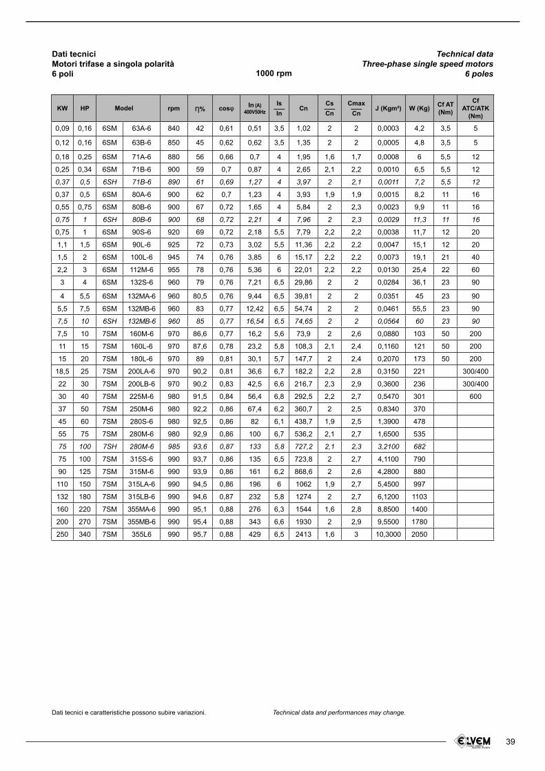
39
KW HP rpm さ% cosl In (A)400V50Hz
Is___In
CnCs___Cn
Cmax___Cn
J (Kgm²) W (Kg)Cf AT(Nm)
CfATC/ATK
(Nm)
0,09 0,16 6SM 63A-6 840 42 0,61 0,51 3,5 1,02 2 2 0,0003 4,2 3,5 5
0,12 0,16 6SM 63B-6 850 45 0,62 0,62 3,5 1,35 2 2 0,0005 4,8 3,5 5
0,18 0,25 6SM 71A-6 880 56 0,66 0,7 4 1,95 1,6 1,7 0,0008 6 5,5 12
0,25 0,34 6SM 71B-6 900 59 0,7 0,87 4 2,65 2,1 2,2 0,0010 6,5 5,5 12
0,37 0,5 6SH 71B-6 890 61 0,69 1,27 4 3,97 2 2,1 0,0011 7,2 5,5 12
0,37 0,5 6SM 80A-6 900 62 0,7 1,23 4 3,93 1,9 1,9 0,0015 8,2 11 16
0,55 0,75 6SM 80B-6 900 67 0,72 1,65 4 5,84 2 2,3 0,0023 9,9 11 16
0,75 1 6SH 80B-6 900 68 0,72 2,21 4 7,96 2 2,3 0,0029 11,3 11 16
0,75 1 6SM 90S-6 920 69 0,72 2,18 5,5 7,79 2,2 2,2 0,0038 11,7 12 20
1,1 1,5 6SM 90L-6 925 72 0,73 3,02 5,5 11,36 2,2 2,2 0,0047 15,1 12 20
1,5 2 6SM 100L-6 945 74 0,76 3,85 6 15,17 2,2 2,2 0,0073 19,1 21 40
2,2 3 6SM 112M-6 955 78 0,76 5,36 6 22,01 2,2 2,2 0,0130 25,4 22 60
3 4 6SM 132S-6 960 79 0,76 7,21 6,5 29,86 2 2 0,0284 36,1 23 90
4 5,5 6SM 132MA-6 960 80,5 0,76 9,44 6,5 39,81 2 2 0,0351 45 23 90
5,5 7,5 6SM 132MB-6 960 83 0,77 12,42 6,5 54,74 2 2 0,0461 55,5 23 90
7,5 10 6SH 132MB-6 960 85 0,77 16,54 6,5 74,65 2 2 0,0564 60 23 90
7,5 10 7SM 160M-6 970 86,6 0,77 16,2 5,6 73,9 2 2,6 0,0880 103 50 200
11 15 7SM 160L-6 970 87,6 0,78 23,2 5,8 108,3 2,1 2,4 0,1160 121 50 200
15 20 7SM 180L-6 970 89 0,81 30,1 5,7 147,7 2 2,4 0,2070 173 50 200
18,5 25 7SM 200LA-6 970 90,2 0,81 36,6 6,7 182,2 2,2 2,8 0,3150 221 300/400
22 30 7SM 200LB-6 970 90,2 0,83 42,5 6,6 216,7 2,3 2,9 0,3600 236 300/400
30 40 7SM 225M-6 980 91,5 0,84 56,4 6,8 292,5 2,2 2,7 0,5470 301 600
37 50 7SM 250M-6 980 92,2 0,86 67,4 6,2 360,7 2 2,5 0,8340 370
45 60 7SM 280S-6 980 92,5 0,86 82 6,1 438,7 1,9 2,5 1,3900 478
55 75 7SM 280M-6 980 92,9 0,86 100 6,7 536,2 2,1 2,7 1,6500 535
75 100 7SH 280M-6 985 93,6 0,87 133 5,8 727,2 2,1 2,3 3,2100 682
75 100 7SM 315S-6 990 93,7 0,86 135 6,5 723,8 2 2,7 4,1100 790
90 125 7SM 315M-6 990 93,9 0,86 161 6,2 868,6 2 2,6 4,2800 880
110 150 7SM 315LA-6 990 94,5 0,86 196 6 1062 1,9 2,7 5,4500 997
132 180 7SM 315LB-6 990 94,6 0,87 232 5,8 1274 2 2,7 6,1200 1103
160 220 7SM 355MA-6 990 95,1 0,88 276 6,3 1544 1,6 2,8 8,8500 1400
200 270 7SM 355MB-6 990 95,4 0,88 343 6,6 1930 2 2,9 9,5500 1780
250 340 7SM 355L6 990 95,7 0,88 429 6,5 2413 1,6 3 10,3000 2050
Model
Dati tecniciMotori trifase a singola polarità6 poli
Technical dataThree-phase single speed motors
6 poles1000 rpm
Dati tecnici e caratteristiche possono subire variazioni. Technical data and performances may change.
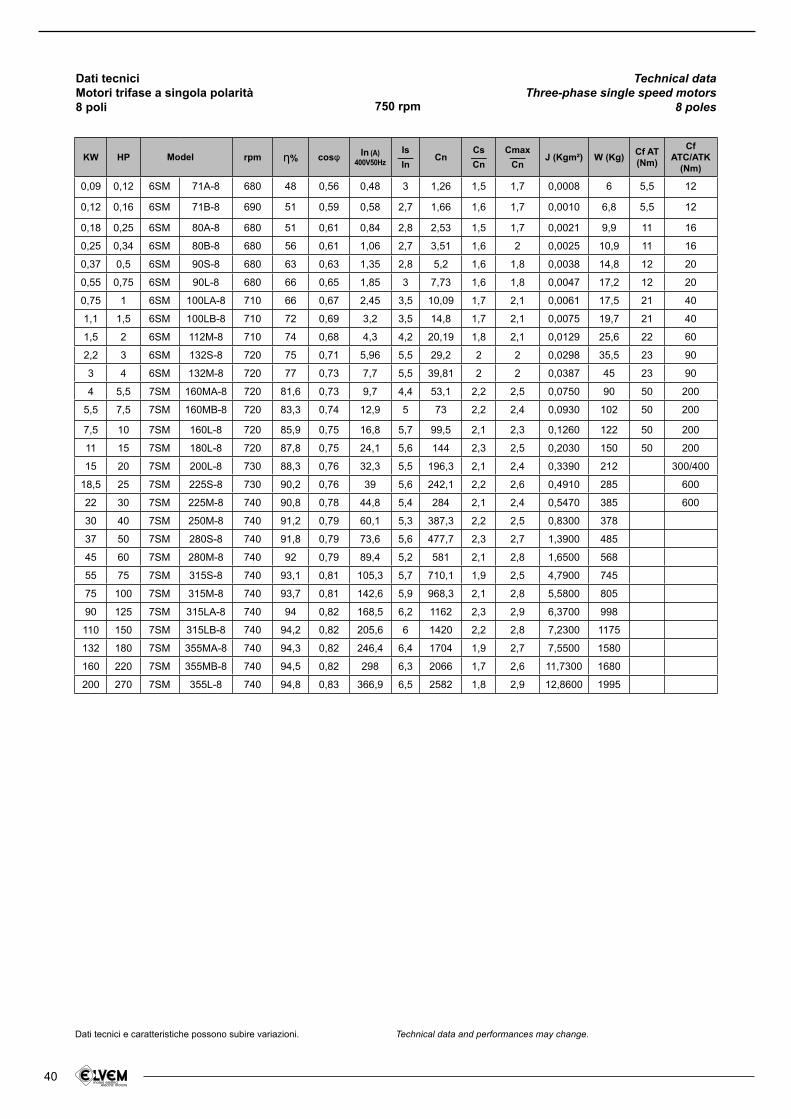
40
KW HP rpm さ% cosl In (A)400V50Hz
Is___In
CnCs___Cn
Cmax___Cn
J (Kgm²) W (Kg)Cf AT(Nm)
CfATC/ATK
(Nm)
0,09 0,12 6SM 71A-8 680 48 0,56 0,48 3 1,26 1,5 1,7 0,0008 6 5,5 12
0,12 0,16 6SM 71B-8 690 51 0,59 0,58 2,7 1,66 1,6 1,7 0,0010 6,8 5,5 12
0,18 0,25 6SM 80A-8 680 51 0,61 0,84 2,8 2,53 1,5 1,7 0,0021 9,9 11 16
0,25 0,34 6SM 80B-8 680 56 0,61 1,06 2,7 3,51 1,6 2 0,0025 10,9 11 16
0,37 0,5 6SM 90S-8 680 63 0,63 1,35 2,8 5,2 1,6 1,8 0,0038 14,8 12 20
0,55 0,75 6SM 90L-8 680 66 0,65 1,85 3 7,73 1,6 1,8 0,0047 17,2 12 20
0,75 1 6SM 100LA-8 710 66 0,67 2,45 3,5 10,09 1,7 2,1 0,0061 17,5 21 40
1,1 1,5 6SM 100LB-8 710 72 0,69 3,2 3,5 14,8 1,7 2,1 0,0075 19,7 21 40
1,5 2 6SM 112M-8 710 74 0,68 4,3 4,2 20,19 1,8 2,1 0,0129 25,6 22 60
2,2 3 6SM 132S-8 720 75 0,71 5,96 5,5 29,2 2 2 0,0298 35,5 23 90
3 4 6SM 132M-8 720 77 0,73 7,7 5,5 39,81 2 2 0,0387 45 23 90
4 5,5 7SM 160MA-8 720 81,6 0,73 9,7 4,4 53,1 2,2 2,5 0,0750 90 50 200
5,5 7,5 7SM 160MB-8 720 83,3 0,74 12,9 5 73 2,2 2,4 0,0930 102 50 200
7,5 10 7SM 160L-8 720 85,9 0,75 16,8 5,7 99,5 2,1 2,3 0,1260 122 50 200
11 15 7SM 180L-8 720 87,8 0,75 24,1 5,6 144 2,3 2,5 0,2030 150 50 200
15 20 7SM 200L-8 730 88,3 0,76 32,3 5,5 196,3 2,1 2,4 0,3390 212 300/400
18,5 25 7SM 225S-8 730 90,2 0,76 39 5,6 242,1 2,2 2,6 0,4910 285 600
22 30 7SM 225M-8 740 90,8 0,78 44,8 5,4 284 2,1 2,4 0,5470 385 600
30 40 7SM 250M-8 740 91,2 0,79 60,1 5,3 387,3 2,2 2,5 0,8300 378
37 50 7SM 280S-8 740 91,8 0,79 73,6 5,6 477,7 2,3 2,7 1,3900 485
45 60 7SM 280M-8 740 92 0,79 89,4 5,2 581 2,1 2,8 1,6500 568
55 75 7SM 315S-8 740 93,1 0,81 105,3 5,7 710,1 1,9 2,5 4,7900 745
75 100 7SM 315M-8 740 93,7 0,81 142,6 5,9 968,3 2,1 2,8 5,5800 805
90 125 7SM 315LA-8 740 94 0,82 168,5 6,2 1162 2,3 2,9 6,3700 998
110 150 7SM 315LB-8 740 94,2 0,82 205,6 6 1420 2,2 2,8 7,2300 1175
132 180 7SM 355MA-8 740 94,3 0,82 246,4 6,4 1704 1,9 2,7 7,5500 1580
160 220 7SM 355MB-8 740 94,5 0,82 298 6,3 2066 1,7 2,6 11,7300 1680
200 270 7SM 355L-8 740 94,8 0,83 366,9 6,5 2582 1,8 2,9 12,8600 1995
Model
Dati tecniciMotori trifase a singola polarità8 poli
Technical dataThree-phase single speed motors
8 poles750 rpm
Dati tecnici e caratteristiche possono subire variazioni. Technical data and performances may change.
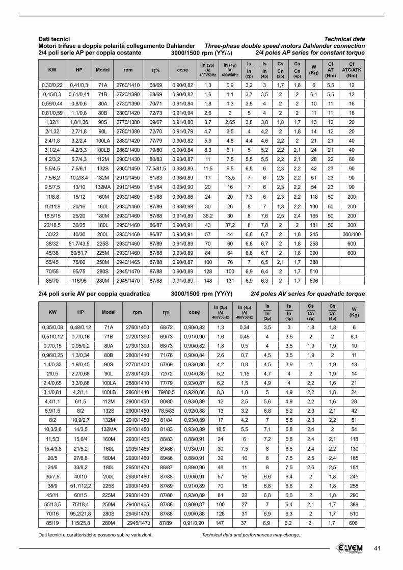
41
KW HP Model rpm さ% coslIn (2p)
(A)400V50Hz
In (4p)(A)
400V50Hz
Is___In
(2p)
Is___In
(4p)
Cs___Cn(2p)
Cs___Cn(4p)
W(Kg)
0,35/0,08 0,48/0,12 71A 2760/1400 68/72 0,90/0,82 1,3 0,34 3,5 3 1,8 1,8 6
0,51/0,12 0,7/0,16 71B 2720/1390 69/73 0,91/0,90 1,6 0,45 4 3,5 2 2 6,1
0,7/0,15 0,95/0,2 80A 2730/1390 68/73 0,90/0,82 1,8 0,5 4 3,5 1,9 1,9 10
0,96/0,25 1,3/0,34 80B 2800/1410 71/76 0,90/0,84 2,6 0,7 4,5 3,5 1,9 2 11
1,4/0,33 1,9/0,45 90S 2770/1400 67/69 0,93/0,86 4,2 0,8 4,5 3,9 2 1,9 13
2/0.5 2,7/0,68 90L 2780/1400 72/72 0,94/0,85 5,2 1,15 4,7 4 2 1,9 14
2,4/0,65 3,3/0,88 100LA 2880/1410 77/79 0,93/0,87 6,2 1,5 4,9 4 2,2 1,6 21
3,1/0,81 4,2/1,1 100LB 2860/1440 79/80,5 0,92/0,86 8,3 1,8 5 4,9 2,2 1,8 24
4,4/1,1 6/1,5 112M 2900/1450 80/80 0,93/0,89 12 2,5 5,6 4,9 2,2 1,6 28
5,9/1,5 8/2 132S 2900/1450 78,5/83 0,92/0,88 13 3,2 6,8 5,2 2,3 2,1 42
8/2 10,9/2,7 132M 2910/1450 81/84 0,93/0,89 17 4,2 7 5,8 2,3 2,2 51
10,3/2,6 14/3,5 132MA 2910/1450 81/83 0,93/0,89 18,5 5,5 7,1 5,8 2,4 2 54
11,5/3 15,6/4 160M 2930/1465 88/83 0,88/0,91 24 6 7,2 5,8 2,4 2,1 118
15,4/3,8 21/5,2 160L 2935/1465 89/86 0,93/0,91 30 7,5 8 6,5 2,4 2,2 130
20/5 27/6,8 180M 2930/1460 89/86 0,88/0,91 39 10 8 7,5 2,5 2,4 165
24/6 33/8,2 180L 2950/1470 88/87 0,89/0,90 48 11 8 7,5 2,6 2,5 181
30/7,5 40/10 200L 2930/1460 87/88 0,90/0,91 57 16 6,6 6,4 2 1,8 245
38/9 51,7/12,2 225S 2930/1460 87/89 0,91/0,89 70 18 6,8 6,6 2 1,8 258
45/11 60/15 225M 2930/1460 87/88 0,93/0,89 84 22 6,8 6,6 2 1,8 290
55/13,5 75/18,4 250M 2940/1465 87/88 0,90/0,87 100 27 7 6,4 2,1 1,7 388
70/16 95,2/21,8 280S 2945/1470 87/88 0,90/0,88 128 31 6,9 6,3 2 1,7 510
85/19 115/25,8 280M 2945/1470 87/89 0,91/0,90 147 37 6,9 6,2 2 1,7 606
KW HP Model rpm さ% coslIn (2p)
(A)400V50Hz
In (4p)(A)
400V50Hz
Is___In
(2p)
Is___In
(4p)
Cs___Cn(2p)
Cs___Cn(4p)
W(Kg)
Cf AT
(Nm)
CfATC/ATK
(Nm)
0,30/0,22 0,41/0,3 71A 2760/1410 68/69 0,90/0,82 1,3 0,9 3,2 3 1,7 1,8 6 5,5 12
0,45/0,3 0,61/0,41 71B 2720/1390 68/69 0,90/0,82 1,6 1,1 3,7 3,5 2 2 6,1 5,5 12
0,59/0,44 0,8/0,6 80A 2730/1390 70/71 0,91/0,84 1,8 1,3 3,8 4 2 2 10 11 16
0,81/0,59 1,1/0,8 80B 2800/1420 72/73 0,91/0,94 2,6 2 5 4 2 2 11 11 16
1,32/1 1,8/1,36 90S 2770/1380 69/67 0,91/0,80 3,7 2,65 3,8 3,8 1,8 1,7 13 12 20
2/1,32 2,7/1,8 90L 2780/1380 72/70 0,91/0,79 4,7 3,5 4 4,2 2 1,8 14 12 20
2,4/1,8 3,2/2,4 100LA 2880/1420 77/79 0,90/0,82 5,9 4,5 4,4 4,6 2,2 2 21 21 40
3,1/2,4 4,2/3,3 100LB 2860/1400 79/80 0,90/0,84 8,3 6,1 5 5,2 2,2 2,1 24 21 40
4,2/3,2 5,7/4,3 112M 2900/1430 80/83 0,93/0,87 11 7,5 5,5 5,5 2,2 2,1 28 22 60
5,5/4,5 7,5/6,1 132S 2900/1450 77,5/81,5 0,93/0,89 11,5 9,5 6,5 6 2,3 2,2 42 23 90
7,5/6,2 10,2/8,4 132M 2910/1450 81/83 0,93/0,89 17 13,5 7 6 2,3 2,2 51 23 90
9,5/7,5 13/10 132MA 2910/1450 81/84 0,93/0,90 20 16 7 6 2,3 2,2 54 23 90
11/8,8 15/12 160M 2930/1460 81/88 0,90/0,86 24 20 7,3 6 2,3 2,2 118 50 200
15/11,8 20/16 160L 2930/1460 87/89 0,93/0,98 30 26 8 7 1,8 2,2 130 50 200
18,5/15 25/20 180M 2930/1460 87/88 0,91/0,89 36,2 30 8 7,6 2,5 2,4 165 50 200
22/18,5 30/25 180L 2950/1460 86/87 0,90/0,91 43 37,2 8 7,8 2 2 181 50 200
30/22 40/30 200L 2930/1460 86/87 0,93/0,91 57 44 6,8 6,7 2 1,8 245 300/400
38/32 51,7/43,5 225S 2930/1460 87/89 0,91/0,89 70 60 6,8 6,7 2 1,8 258 600
45/38 60/51,7 225M 2930/1460 87/88 0,93/0,89 84 64 6,8 6,7 2 1,8 290 600
55/45 75/60 250M 2940/1465 87/88 0,90/0,87 100 76 7 6,5 2,1 1,7 388
70/55 95/75 280S 2945/1470 87/88 0,90/0,89 128 100 6,9 6,4 2 1,7 510
85/70 116/95 280M 2945/1470 87/88 0,91/0,89 148 131 6,9 6,3 2 1,7 606
2/4 poli serie AV per coppia quadratica
Dati tecniciMotori trifase a doppia polarità collegamento Dahlander2/4 poli serie AP per coppia costante
2/4 poles AV series for quadratic torque
Technical dataThree-phase double speed motors Dahlander connection
2/4 poles AP series for constant torque
3000/1500 rpm (YY/Y)
3000/1500 rpm (YY/∆)
Dati tecnici e caratteristiche possono subire variazioni. Technical data and performances may change.
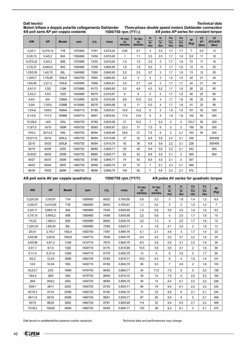
42
KW HP Model rpm さ% coslIn (4p)
(A)400V50Hz
In (8p)(A)
400V50Hz
Is___In
(4p)
Is___In
(8p)
Cs___Cn(4p)
Cs___Cn(8p)
W(Kg)
Cf AT
(Nm)
CfATC/ATK
(Nm)
0,2/0,1 0,27/0,14 71B 1370/660 73/51 0,87/0,62 0,65 0,7 3 2,5 1,7 1,7 7 5,5 12
0,3/0,15 0,4/0,2 80A 1350/680 74/50 0,87/0,62 1 1,1 3,5 2,5 1,7 1,9 9,5 11 16
0,37/0,22 0,5/0,3 80B 1370/680 72/53 0,87/0,62 1,4 1,5 3,5 3 1,7 1,9 10 11 16
0,7/0,37 0,95/0,5 90S 1350/680 72/58 0,89/0,60 1,8 1,9 3,5 3 1,7 1,8 12 12 20
1,03/0,55 1,4/0,75 90L 1340/680 72/60 0,89/0,65 2,5 2,5 3,7 3 1,7 1,9 13 12 20
1,25/0,7 1,7/0,95 100LA 1400/700 76/64 0,89/0,62 3,2 3 4 3 1,5 1,5 22 21 40
1,6/0,88 2,2/1,2 100LB 1420/690 79/66 0,88/0,61 3,9 3,7 4,5 3 1,7 1,7 24 21 40
2,4/1,5 3,3/2 112M 1370/680 81/73 0,89/0,65 5,5 4,8 4,5 3,5 1,7 1,8 26 22 60
3,3/2,2 4,5/3 132S 1420/690 80/75 0,91/0,67 8 6 5 4 1,7 1,8 46 23 90
4,4/3 6/4 132MA 1410/690 82/78 0,91/0,65 9,8 10,5 5,5 4 1,7 1,8 50 23 90
5,5/4 7,5/5,5 132MB 1410/690 82/79 0,90/0,66 12 11 5,5 4 1,7 1,8 51 23 90
7,5/4,8 10/6,5 160MA 1430/710 87/80 0,90/0,61 16,9 12,8 6 5 1,8 1,8 101 50 200
8,1/5,5 11/7,5 160MB 1430/710 88/81 0,90/0,62 17,6 13,8 6 5 1,8 1,8 102 50 200
10,3/6,6 14/9 160L 1450/720 87/85 0,92/0,68 21 15,3 7 5,5 2 2 103,7 50 200
11,8/7,5 16/10 180M 1450/720 85/83 0,90/0,67 23,3 17 7,5 6 2 2 159 50 200
15/9,2 20/12,5 180L 1450/720 86/84 0,90/0,66 29,8 21 7,5 6 2 2,1 163 50 200
18,5/11,8 25/16 200LA 1455/725 86/84 0,91/0,69 37 24 6,8 5,6 2,2 2,1 226 300/400
22/15 30/20 200LB 1455/725 86/84 0,91/0,70 42 36 6,8 5,6 2,2 2,1 228 300/400
30/19 40/26 225S 1455/725 88/85 0,90/0,71 55 44 6,9 5,6 2,2 2,1 242 600
33,8/22 46/30 225M 1455/725 88/85 0,90/0,71 63 52 6,8 5,5 2,1 2 265 600
40/27 55/37 250M 1460/730 87/85 0,89/0,71 74 63 6,9 5,5 2,1 2 357
48/32 65/44 280S 1460/730 89/88 0,88/0,70 87 72 7 5,7 2,3 2,1 469
56/38 76/52 280M 1460/730 88/86 0,89/0,70 100 82 7 5,8 2,3 2,1 472
KW HP Model rpm さ% coslIn (4p)
(A)400V50Hz
In (8p)(A)
400V50Hz
Is___In
(4p)
Is___In
(8p)
Cs___Cn(4p)
Cs___Cn(8p)
W(Kg)
0,22/0,05 0,3/0,07 71A 1380/650 68/52 0,78/0,60 0,8 0,3 3 1,8 1,4 1,2 6,5
0,3/0,07 0,41/0,09 71B 1380/650 68/53 0,79/0,61 1,1 0,4 3 2 1,5 1,2 7
0,5/0,11 0,68/0,15 80A 1380/685 73/55 0,80/0,60 1,5 0,6 3,5 2,5 1,6 1,6 9,5
0,7/0,15 0,95/0,2 80B 1390/660 74/56 0,83/0,66 2,2 0,8 4 2,5 1,7 1,6 10
1/0,22 1,36/0,3 90S 1400/690 68/62 0,83/0,70 3,2 1,3 4 2,5 1,7 1,6 12
1,32/0,33 1,8/0,45 90L 1400/680 72/66 0,82/0,71 4 1,6 4,1 2,5 2 1,6 13
2/0,51 2,7/0,7 100LA 1420/700 73/67 0,89/0,75 5,1 2,1 4,5 3 1,7 1,4 22
2,6/0,66 3,6/0,9 100LB 1440/710 76/69 0,89/0,75 6,4 2,6 5,2 3,1 2,2 1,6 24
3,6/0,96 4,9/1,3 112M 1410/710 78/75 0,86/0,70 8,5 3,5 5,5 3,1 2,2 1,6 26
4,5/1,1 6/1,5 132S 1430/710 81/75 0,81/0,69 10,5 3,8 5,5 3,1 2 1,6 46
6,1/1,4 8,3/1,9 132M 1440/710 81/78 0,90/0,75 13 5 6 3,5 2 1,7 50
9/2,2 12,2/3 160M 1460/725 87/83 0,87/0,71 18,5 5,5 6 4 1,6 1,4 101
12/3 16,3/4 160L 1430/715 87/82 0,85/0,70 26 9,3 7 4,5 2 1,6 103
16,2/3,7 22/5 180M 1470/740 85/83 0,88/0,71 34 11,5 7,5 5 2 2,2 158
19/4,5 26/6 180L 1470/730 86/84 0,87/0,72 39 14 7,5 5 2,5 2,2 163
26/6 35/8,2 200L 1455/725 86/84 0,89/0,70 49 14 6,4 6,1 2,3 2,2 226
35/8,1 48/11 225S 1455/725 87/83 0,90/0,71 66 19 6,5 6,1 2,2 2,2 242
42/10,3 57/14 225M 1455/725 87/82 0,90/0,70 76 23 6,6 6 2,1 2,1 244
48/11,8 65/16 250M 1460/725 88/81 0,90/0,71 87 26 6,5 6 2 2,1 356
63/15 86/20 280S 1460/730 87/81 0,89/0,69 114 32 6,4 6,2 2,1 2,2 469
75/18,5 100/25 280M 1460/730 84/82 0,88/0,71 133 39 6,3 6,1 2 2,1 472
Dati tecnici e caratteristiche possono subire variazioni. Technical data and performances may change.
Dati tecniciMotori trifase a doppia polarità collegamento Dahlander4/8 poli serie AP per coppia costante
Technical dataThree-phase double speed motors Dahlander connection
4/8 poles AP series for constant torque1500/750 rpm (YY/∆)
4/8 poli serie AV per coppia quadratica 4/8 poles AV series for quadratic torque1500/750 rpm (YY/Y)
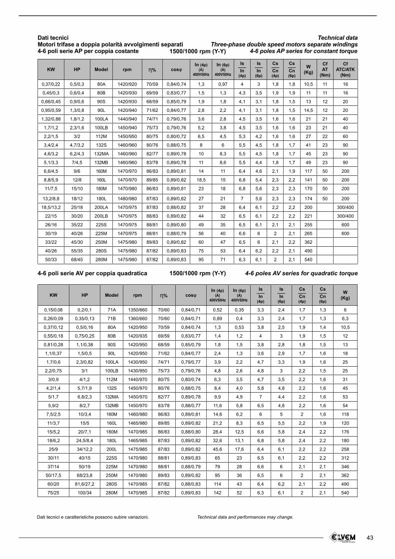
43
KW HP Model rpm さ% coslIn (4p)
(A)400V50Hz
In (6p)(A)
400V50Hz
Is___In
(4p)
Is___In
(6p)
Cs___Cn(4p)
Cs___Cn(6p)
W(Kg)
Cf AT
(Nm)
CfATC/ATK
(Nm)
0,37/0,22 0,5/0,3 80A 1420/920 70/59 0,84/0,74 1,3 0,97 4 3 1,8 1,8 10,5 11 16
0,45/0,3 0,6/0,4 80B 1420/930 69/59 0,83/0,77 1,5 1,3 4,3 3,5 1,9 1,9 11 11 16
0,66/0,45 0,9/0,6 90S 1420/930 68/59 0,85/0,79 1,9 1,8 4,1 3,1 1,8 1,5 13 12 20
0,95/0,59 1,3/0,8 90L 1420/940 71/62 0,84/0,77 2,8 2,2 4,1 3,1 1,8 1,5 14,5 12 20
1,32/0,88 1,8/1,2 100LA 1440/940 74/71 0,79/0,76 3,6 2,8 4,5 3,5 1,6 1,6 21 21 40
1,7/1,2 2,3/1,6 100LB 1450/940 75/73 0,79/0,76 5,2 3,8 4,5 3,5 1,6 1,6 23 21 40
2,2/1,5 3/2 112M 1450/950 80/75 0,80/0,72 6,5 4,5 5,3 4,2 1,6 1,6 27 22 60
3,4/2,4 4,7/3,2 132S 1460/960 80/76 0,88/0,75 8 6 5,5 4,5 1,8 1,7 41 23 90
4,6/3,2 6,2/4,3 132MA 1460/960 82/77 0,89/0,78 10 8,3 5,5 4,5 1,8 1,7 45 23 90
5,1/3,3 7/4,5 132MB 1460/960 83/78 0,89/0,78 11 8,6 5,5 4,4 1,8 1,7 49 23 90
6,6/4,5 9/6 160M 1470/970 86/83 0,89/0,81 14 11 6,4 4,6 2,1 1,9 117 50 200
8,8/5,9 12/8 160L 1470/970 89/85 0,89/0,82 18,5 15 6,8 5,4 2,3 2,2 141 50 200
11/7,5 15/10 180M 1470/980 86/83 0,89/0,81 23 18 6,8 5,6 2,3 2,3 170 50 200
13,2/8,8 18/12 180L 1480/980 87/83 0,89/0,82 27 21 7 5,6 2,3 2,3 174 50 200
18,5/13,2 25/18 200LA 1470/975 87/83 0,88/0,82 37 28 6,4 6,1 2,2 2,2 200 300/400
22/15 30/20 200LB 1470/975 88/83 0,89/0,82 44 32 6,5 6,1 2,2 2,2 221 300/400
26/16 35/22 225S 1470/975 88/81 0,89/0,80 49 35 6,5 6,1 2,1 2,1 255 600
30/19 40/26 225M 1470/975 88/81 0,88/0,79 56 40 6,6 6 2 2,1 265 600
33/22 45/30 250M 1475/980 89/83 0,89/0,82 60 47 6,5 6 2,1 2,2 362
40/26 55/35 280S 1475/980 87/82 0,89/0,83 75 53 6,4 6,2 2,2 2,1 490
50/33 68/45 280M 1475/980 87/82 0,89/0,83 95 71 6,3 6,1 2 2,1 540
KW HP Model rpm さ% coslIn (4p)
(A)400V50Hz
In (6p)(A)
400V50Hz
Is___In
(4p)
Is___In
(6p)
Cs___Cn(4p)
Cs___Cn(6p)
W(Kg)
0,15/0,08 0,2/0,1 71A 1350/660 70/60 0,84/0,71 0,52 0,35 3,3 2,4 1,7 1,3 6
0,26/0,09 0,35/0,13 71B 1360/660 70/60 0,84/0,71 0,89 0,4 3,3 2,4 1,7 1,3 6,3
0,37/0,12 0,5/0,16 80A 1420/950 70/59 0,84/0,74 1,3 0,53 3,8 2,5 1,9 1,4 10,5
0,55/0,18 0,75/0,25 80B 1420/935 69/59 0,83/0,77 1,4 1,2 4 3 1,9 1,5 12
0,81/0,28 1,1/0,38 90S 1420/950 68/59 0,85/0,79 1,8 1,5 3,8 2,8 1,8 1,5 13
1,1/0,37 1,5/0,5 90L 1420/950 71/62 0,84/0,77 2,4 1,3 3,6 2,9 1,7 1,6 18
1,7/0,6 2,3/0,82 100LA 1430/950 74/71 0,79/0,77 3,9 2,2 4,7 3,3 1,9 1,6 25
2,2/0,75 3/1 100LB 1430/950 75/73 0,79/0,76 4,8 2,6 4,8 3 2,2 1,5 25
3/0,9 4/1,2 112M 1440/970 80/75 0,80/0,74 6,3 3,5 4,7 3,5 2,2 1,6 31
4,2/1,4 5,7/1,9 132S 1450/970 80/76 0,88/0,75 8,4 4,0 5,8 4,8 2,2 1,6 45
5/1,7 6,8/2,3 132MA 1450/970 82/77 0,89/0,78 9,9 4,9 7 4,4 2,2 1,6 53
5,9/2 8/2,7 132MB 1450/970 83/78 0,88/0,77 11,6 5,8 6,5 4,8 2,2 1,6 54
7,5/2,5 10/3,4 160M 1460/980 86/83 0,89/0,81 14,6 6,2 6 5 2 1,6 118
11/3,7 15/5 160L 1465/980 89/85 0,89/0,82 21,2 8,3 6,5 5,5 2,2 1,9 120
15/5,2 20/7,1 180M 1470/985 86/83 0,88/0,80 28,4 12,5 6,6 5,8 2,4 2,2 176
18/6,2 24,5/8,4 180L 1465/985 87/83 0,89/0,82 32,6 13,1 6,8 5,8 2,4 2,2 180
25/9 34/12,2 200L 1475/985 87/83 0,89/0,82 45,6 17,6 6,4 6,1 2,2 2,2 258
30/11 40/15 225S 1470/980 88/81 0,89/0,83 65 23 6,5 6,1 2,2 2,2 312
37/14 50/19 225M 1470/980 88/81 0,88/0,79 79 28 6,6 6 2,1 2,1 346
50/17,5 68/23,8 250M 1470/980 89/83 0,89/0,82 95 36 6,5 6 2 2,1 362
60/20 81,6/27,2 280S 1470/985 87/82 0,88/0,83 114 43 6,4 6,2 2,1 2,2 490
75/25 100/34 280M 1470/985 87/82 0,89/0,83 142 52 6,3 6,1 2 2,1 540
Dati tecnici e caratteristiche possono subire variazioni. Technical data and performances may change.
Dati tecniciMotori trifase a doppia polarità avvolgimenti separati4-6 poli serie AP per coppia costante
Technical dataThree-phase double speed motors separate windings
4-6 poles AP series for constant torque1500/1000 rpm (Y-Y)
4-6 poli serie AV per coppia quadratica 4-6 poles AV series for quadratic torque1500/1000 rpm (Y-Y)
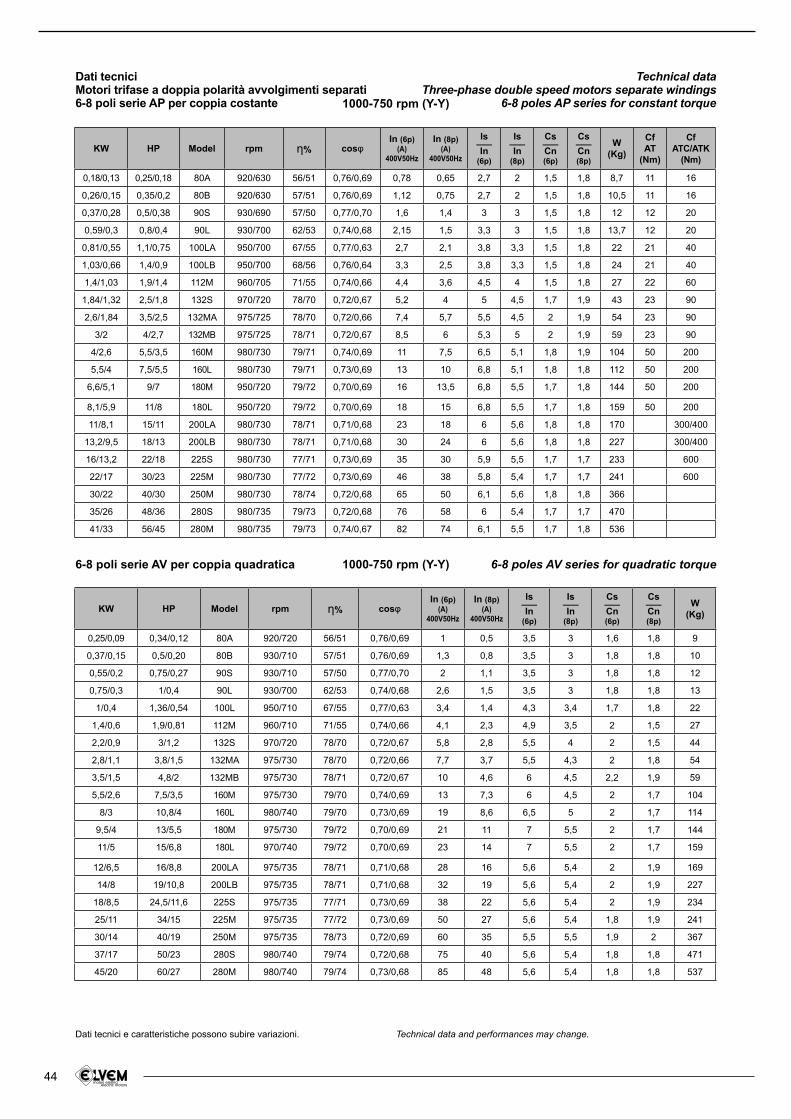
44
KW HP Model rpm さ% coslIn (6p)
(A)400V50Hz
In (8p)(A)
400V50Hz
Is___In
(6p)
Is___In
(8p)
Cs___Cn(6p)
Cs___Cn(8p)
W(Kg)
Cf AT
(Nm)
CfATC/ATK
(Nm)
0,18/0,13 0,25/0,18 80A 920/630 56/51 0,76/0,69 0,78 0,65 2,7 2 1,5 1,8 8,7 11 16
0,26/0,15 0,35/0,2 80B 920/630 57/51 0,76/0,69 1,12 0,75 2,7 2 1,5 1,8 10,5 11 16
0,37/0,28 0,5/0,38 90S 930/690 57/50 0,77/0,70 1,6 1,4 3 3 1,5 1,8 12 12 20
0,59/0,3 0,8/0,4 90L 930/700 62/53 0,74/0,68 2,15 1,5 3,3 3 1,5 1,8 13,7 12 20
0,81/0,55 1,1/0,75 100LA 950/700 67/55 0,77/0,63 2,7 2,1 3,8 3,3 1,5 1,8 22 21 40
1,03/0,66 1,4/0,9 100LB 950/700 68/56 0,76/0,64 3,3 2,5 3,8 3,3 1,5 1,8 24 21 40
1,4/1,03 1,9/1,4 112M 960/705 71/55 0,74/0,66 4,4 3,6 4,5 4 1,5 1,8 27 22 60
1,84/1,32 2,5/1,8 132S 970/720 78/70 0,72/0,67 5,2 4 5 4,5 1,7 1,9 43 23 90
2,6/1,84 3,5/2,5 132MA 975/725 78/70 0,72/0,66 7,4 5,7 5,5 4,5 2 1,9 54 23 90
3/2 4/2,7 132MB 975/725 78/71 0,72/0,67 8,5 6 5,3 5 2 1,9 59 23 90
4/2,6 5,5/3,5 160M 980/730 79/71 0,74/0,69 11 7,5 6,5 5,1 1,8 1,9 104 50 200
5,5/4 7,5/5,5 160L 980/730 79/71 0,73/0,69 13 10 6,8 5,1 1,8 1,8 112 50 200
6,6/5,1 9/7 180M 950/720 79/72 0,70/0,69 16 13,5 6,8 5,5 1,7 1,8 144 50 200
8,1/5,9 11/8 180L 950/720 79/72 0,70/0,69 18 15 6,8 5,5 1,7 1,8 159 50 200
11/8,1 15/11 200LA 980/730 78/71 0,71/0,68 23 18 6 5,6 1,8 1,8 170 300/400
13,2/9,5 18/13 200LB 980/730 78/71 0,71/0,68 30 24 6 5,6 1,8 1,8 227 300/400
16/13,2 22/18 225S 980/730 77/71 0,73/0,69 35 30 5,9 5,5 1,7 1,7 233 600
22/17 30/23 225M 980/730 77/72 0,73/0,69 46 38 5,8 5,4 1,7 1,7 241 600
30/22 40/30 250M 980/730 78/74 0,72/0,68 65 50 6,1 5,6 1,8 1,8 366
35/26 48/36 280S 980/735 79/73 0,72/0,68 76 58 6 5,4 1,7 1,7 470
41/33 56/45 280M 980/735 79/73 0,74/0,67 82 74 6,1 5,5 1,7 1,8 536
KW HP Model rpm さ% coslIn (6p)
(A)400V50Hz
In (8p)(A)
400V50Hz
Is___In
(6p)
Is___In
(8p)
Cs___Cn(6p)
Cs___Cn(8p)
W(Kg)
0,25/0,09 0,34/0,12 80A 920/720 56/51 0,76/0,69 1 0,5 3,5 3 1,6 1,8 9
0,37/0,15 0,5/0,20 80B 930/710 57/51 0,76/0,69 1,3 0,8 3,5 3 1,8 1,8 10
0,55/0,2 0,75/0,27 90S 930/710 57/50 0,77/0,70 2 1,1 3,5 3 1,8 1,8 12
0,75/0,3 1/0,4 90L 930/700 62/53 0,74/0,68 2,6 1,5 3,5 3 1,8 1,8 13
1/0,4 1,36/0,54 100L 950/710 67/55 0,77/0,63 3,4 1,4 4,3 3,4 1,7 1,8 22
1,4/0,6 1,9/0,81 112M 960/710 71/55 0,74/0,66 4,1 2,3 4,9 3,5 2 1,5 27
2,2/0,9 3/1,2 132S 970/720 78/70 0,72/0,67 5,8 2,8 5,5 4 2 1,5 44
2,8/1,1 3,8/1,5 132MA 975/730 78/70 0,72/0,66 7,7 3,7 5,5 4,3 2 1,8 54
3,5/1,5 4,8/2 132MB 975/730 78/71 0,72/0,67 10 4,6 6 4,5 2,2 1,9 59
5,5/2,6 7,5/3,5 160M 975/730 79/70 0,74/0,69 13 7,3 6 4,5 2 1,7 104
8/3 10,8/4 160L 980/740 79/70 0,73/0,69 19 8,6 6,5 5 2 1,7 114
9,5/4 13/5,5 180M 975/730 79/72 0,70/0,69 21 11 7 5,5 2 1,7 144
11/5 15/6,8 180L 970/740 79/72 0,70/0,69 23 14 7 5,5 2 1,7 159
12/6,5 16/8,8 200LA 975/735 78/71 0,71/0,68 28 16 5,6 5,4 2 1,9 169
14/8 19/10,8 200LB 975/735 78/71 0,71/0,68 32 19 5,6 5,4 2 1,9 227
18/8,5 24,5/11,6 225S 975/735 77/71 0,73/0,69 38 22 5,6 5,4 2 1,9 234
25/11 34/15 225M 975/735 77/72 0,73/0,69 50 27 5,6 5,4 1,8 1,9 241
30/14 40/19 250M 975/735 78/73 0,72/0,69 60 35 5,5 5,5 1,9 2 367
37/17 50/23 280S 980/740 79/74 0,72/0,68 75 40 5,6 5,4 1,8 1,8 471
45/20 60/27 280M 980/740 79/74 0,73/0,68 85 48 5,6 5,4 1,8 1,8 537
Dati tecnici e caratteristiche possono subire variazioni. Technical data and performances may change.
Dati tecniciMotori trifase a doppia polarità avvolgimenti separati6-8 poli serie AP per coppia costante
Technical dataThree-phase double speed motors separate windings
6-8 poles AP series for constant torque1000-750 rpm (Y-Y)
6-8 poli serie AV per coppia quadratica 6-8 poles AV series for quadratic torque1000-750 rpm (Y-Y)
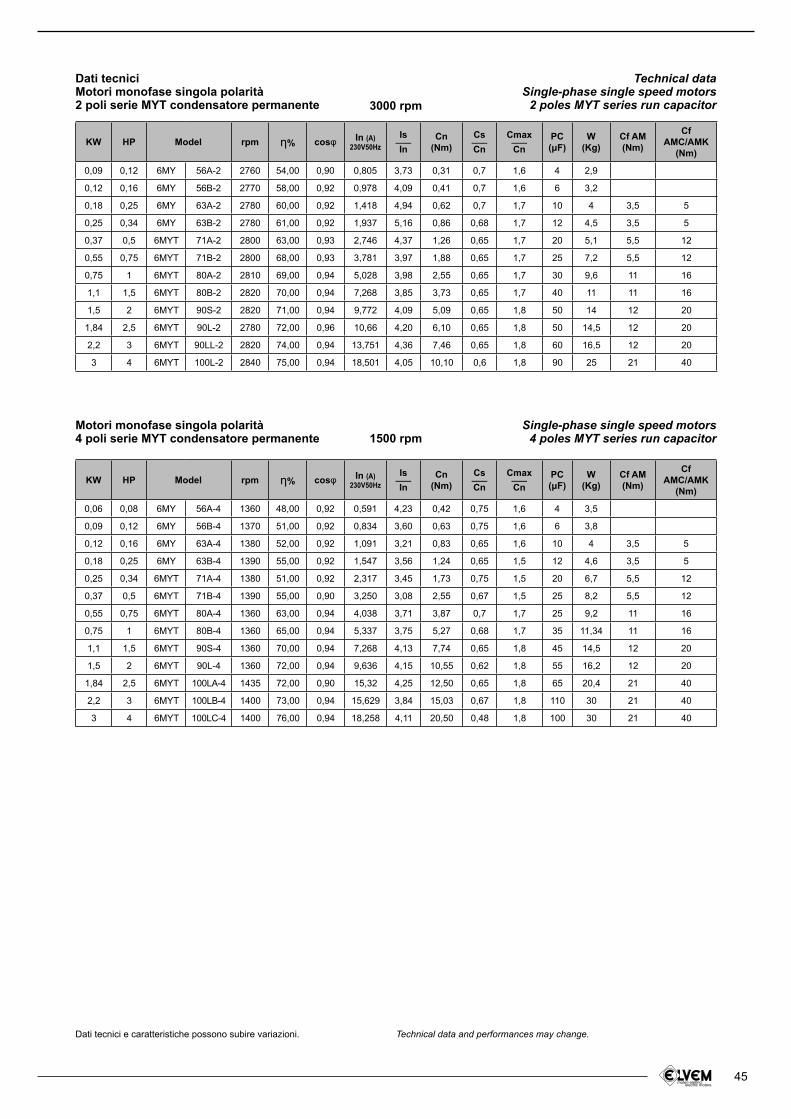
45
Motori monofase singola polarità4 poli serie MYT condensatore permanente
Dati tecniciMotori monofase singola polarità2 poli serie MYT condensatore permanente
Single-phase single speed motors4 poles MYT series run capacitor
Technical dataSingle-phase single speed motors
2 poles MYT series run capacitor
1500 rpm
3000 rpm
KW HP rpm さ% cosl In (A)230V50Hz
Is___In
Cn(Nm)
Cs___Cn
Cmax___Cn
PC(たF)
W (Kg)
Cf AM(Nm)
Cf AMC/AMK
(Nm)
0,09 0,12 6MY 56A-2 2760 54,00 0,90 0,805 3,73 0,31 0,7 1,6 4 2,9
0,12 0,16 6MY 56B-2 2770 58,00 0,92 0,978 4,09 0,41 0,7 1,6 6 3,2
0,18 0,25 6MY 63A-2 2780 60,00 0,92 1,418 4,94 0,62 0,7 1,7 10 4 3,5 5
0,25 0,34 6MY 63B-2 2780 61,00 0,92 1,937 5,16 0,86 0,68 1,7 12 4,5 3,5 5
0,37 0,5 6MYT 71A-2 2800 63,00 0,93 2,746 4,37 1,26 0,65 1,7 20 5,1 5,5 12
0,55 0,75 6MYT 71B-2 2800 68,00 0,93 3,781 3,97 1,88 0,65 1,7 25 7,2 5,5 12
0,75 1 6MYT 80A-2 2810 69,00 0,94 5,028 3,98 2,55 0,65 1,7 30 9,6 11 16
1,1 1,5 6MYT 80B-2 2820 70,00 0,94 7,268 3,85 3,73 0,65 1,7 40 11 11 16
1,5 2 6MYT 90S-2 2820 71,00 0,94 9,772 4,09 5,09 0,65 1,8 50 14 12 20
1,84 2,5 6MYT 90L-2 2780 72,00 0,96 10,66 4,20 6,10 0,65 1,8 50 14,5 12 20
2,2 3 6MYT 90LL-2 2820 74,00 0,94 13,751 4,36 7,46 0,65 1,8 60 16,5 12 20
3 4 6MYT 100L-2 2840 75,00 0,94 18,501 4,05 10,10 0,6 1,8 90 25 21 40
KW HP rpm さ% cosl In (A)230V50Hz
Is___In
Cn(Nm)
Cs___Cn
Cmax___Cn
PC(たF)
W (Kg)
Cf AM(Nm)
Cf AMC/AMK
(Nm)
0,06 0,08 6MY 56A-4 1360 48,00 0,92 0,591 4,23 0,42 0,75 1,6 4 3,5
0,09 0,12 6MY 56B-4 1370 51,00 0,92 0,834 3,60 0,63 0,75 1,6 6 3,8
0,12 0,16 6MY 63A-4 1380 52,00 0,92 1,091 3,21 0,83 0,65 1,6 10 4 3,5 5
0,18 0,25 6MY 63B-4 1390 55,00 0,92 1,547 3,56 1,24 0,65 1,5 12 4,6 3,5 5
0,25 0,34 6MYT 71A-4 1380 51,00 0,92 2,317 3,45 1,73 0,75 1,5 20 6,7 5,5 12
0,37 0,5 6MYT 71B-4 1390 55,00 0,90 3,250 3,08 2,55 0,67 1,5 25 8,2 5,5 12
0,55 0,75 6MYT 80A-4 1360 63,00 0,94 4,038 3,71 3,87 0,7 1,7 25 9,2 11 16
0,75 1 6MYT 80B-4 1360 65,00 0,94 5,337 3,75 5,27 0,68 1,7 35 11,34 11 16
1,1 1,5 6MYT 90S-4 1360 70,00 0,94 7,268 4,13 7,74 0,65 1,8 45 14,5 12 20
1,5 2 6MYT 90L-4 1360 72,00 0,94 9,636 4,15 10,55 0,62 1,8 55 16,2 12 20
1,84 2,5 6MYT 100LA-4 1435 72,00 0,90 15,32 4,25 12,50 0,65 1,8 65 20,4 21 40
2,2 3 6MYT 100LB-4 1400 73,00 0,94 15,629 3,84 15,03 0,67 1,8 110 30 21 40
3 4 6MYT 100LC-4 1400 76,00 0,94 18,258 4,11 20,50 0,48 1,8 100 30 21 40
Model
Model
Dati tecnici e caratteristiche possono subire variazioni. Technical data and performances may change.
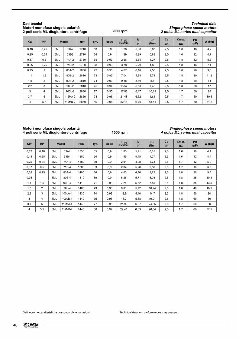
46
Motori monofase singola polarità4 poli serie ML disgiuntore centrifugo
Dati tecniciMotori monofase singola polarità2 poli serie ML disgiuntore centrifugo
Single-phase speed motors4 poles ML series dual capacitor
Technical dataSingle-phase speed motors
2 poles ML series dual capacitor
1500 rpm
3000 rpm
KW HP rpm さ% cosl In (A)230V50Hz
Is___In
Cn(Nm)
Cs___Cn
Cmax___Cn
PC(たF) W (Kg)
0,18 0,25 6ML 63A2 2710 63 0,9 1,38 5,80 0,63 2,5 1,6 10 4,2
0,25 0,34 6ML 63B2 2710 64 0,9 1,89 5,29 0,88 2,5 1,6 12 4,7
0,37 0,5 6ML 71A-2 2780 65 0,93 2,66 5,64 1,27 2,5 1,8 12 5,3
0,55 0,75 6ML 71B-2 2790 68 0,93 3,78 5,29 1,88 2,5 1,8 16 7,4
0,75 1 6ML 80A-2 2800 72 0,93 4,87 6,16 2,56 2,5 1,8 20 9,5
1,1 1,5 6ML 80B-2 2810 73 0,93 7,04 5,68 3,74 2,5 1,8 30 11,2
1,5 2 6ML 90S-2 2810 74 0,93 9,48 5,80 5,1 2,5 1,8 40 14
2,2 3 6ML 90L-2 2810 75 0,94 13,57 5,53 7,48 2,5 1,8 50 17
3 4 6ML 100L-2 2830 77 0,95 17,83 6,17 10,13 2,5 1,7 60 25
3,7 5 6ML 112MA-2 2850 78 0,96 21,48 6,52 12,4 2,5 1,7 60 30,5
4 5,5 6ML 112MB-2 2850 80 0,98 22,18 6,76 13,41 2,5 1,7 60 31,5
KW HP rpm さ% cosl In (A)230V50Hz
Is___In
Cn(Nm)
Cs___Cn
Cmax___Cn
PC(たF) W (Kg)
0,12 0,16 6ML 63A4 1350 55 0,9 1,05 5,71 0,85 2,5 1,6 10 4,1
0,18 0,25 6ML 63B4 1350 56 0,9 1,55 5,48 1,27 2,5 1,6 12 4,4
0,25 0,34 6ML 71A-4 1380 60 0,9 2,01 4,98 1,73 2,5 1,7 12 5,9
0,37 0,5 6ML 71B-4 1380 63 0,9 2,84 5,28 2,56 2,5 1,7 16 6,9
0,55 0,75 6ML 80A-4 1400 66 0,9 4,03 4,96 3,75 2,5 1,8 20 9,6
0,75 1 6ML 80B-4 1410 69 0,9 5,25 5,71 5,08 2,5 1,8 25 10,8
1,1 1,5 6ML 90S-4 1410 71 0,93 7,24 5,52 7,45 2,5 1,8 35 13,5
1,5 2 6ML 90L-4 1400 73 0,93 9,61 5,72 10,24 2,5 1,8 40 16,5
2,2 3 6ML 100LA-4 1430 74 0,93 13,9 5,40 14,7 2,5 1,8 50 24
3 4 6ML 100LB-4 1440 75 0,93 18,7 5,88 19,91 2,5 1,8 60 30
3,7 5 6ML 112MA-4 1440 77 0,95 21,99 6,37 24,55 2,5 1,7 60 36
4 5,5 6ML 112MB-4 1440 80 0,97 22,41 6,69 26,54 2,5 1,7 60 37,5
Model
Model
Dati tecnici e caratteristiche possono subire variazioni. Technical data and performances may change.
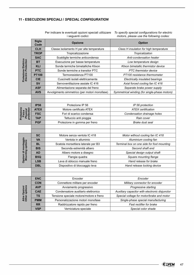
47
Opz
ioni
di m
onta
ggio
Mou
ntin
g op
tions
Alt
re O
pzi
on
iO
ther
opt
ions
11 - ESECUZIONI SPECIALI / SPECIAL CONFIGURATION
Per indicare le eventuali opzioni speciali utilizzare i seguenti codici:
To specify special conigurations for electric motors, please use the following codes:
Sigla Code Opzione Option
CLH Classe isolamento H per alte temperature Class H insulation for high temperatureTROP Tropicalizzazione Tropicalization
SAC Scaldiglie termiche anticondensa Anti-condensation heaterBT Esecuzione per basse temperature Low temperature design
KLI Sonde termiche bimetalliche Klixon Klixon bimetallic thermistor devicePTC Sonde termiche a transitor PTC PTC thermistor device
PT100 Termoresistenza PT100 PT100 resistance thermometerCIE Cuscinetti isolati elettricamente Electrically insulated bearings
SV Servoventilazione assiale IC 416 Axial forced cooling fan IC 416ASF Alimentazione separata del freno Separate brake power supplyAVS Avvolgimento simmetrico (per motori monofase) Symmetrical winding (for single-phase motors)
IP56 Protezione IP 56 IP 56 protectionATEX Motore certiicato ATEX ATEX certiicationFSC Fori di scarico condensa Condensation drainage holes
TAP Tettuccio anti pioggia Rain cover
PGF Protezione in gomma per freno Brake dust seal
SC Motore senza ventola IC 418 Motor without cooling fan IC 418VA Ventola in alluminio Aluminium cooling fanBL Scatola morsettiera laterale per B3 Terminal box on one side for foot mountingBIS Seconda estremità albero Second shaft endAD Albero motore a disegno Special design output shaft
B5Q Flangia quadra Square mounting langeLSB Leva di sblocco manuale freno Hand release for brakeDBL Dispositivo di bloccaggio leva Hand release locking device
ENC Encoder Encoder
CON Connettore militare per encoder Military connector for encoderAVP Avviamento progressivo Progressive starting
CAE Condensatore ausiliario elettronico Auxiliary capacitor with electronic disjunctorTS Tensione speciale motore/motore e freno Special voltage for motor/brake and motor
PMM Personalizzazione motori monofase Single-phase special manufacturingRR Raddrizzatore rapido per freno Fast rectiier for brakeVSP Verniciatura speciale Special color shade
Pro
tezi
on
e E
lett
rica
Elec
tric
Pro
tect
ion
Pro
tezi
on
eF
isic
aPh
ysic
alpr
otec
tion
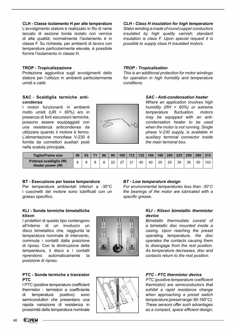
48
TROP - TropicalizzazioneProtezione aggiuntiva sugli avvolgimenti dello statore per l’utilizzo in ambienti particolarmente umidi e caldi.
SAC - Scaldiglia termiche anti-condensaI motori funzionanti in ambienti molto umidi (UR > 60%) e/o in presenza di forti escursioni termiche, possono essere equipaggiati con una resistenza anticondensa da utilizzare quando il motore è fermo. L’alimentazione monofase V-230 è fornita da connettori ausiliari posti nella scatola principale.
SAC - Anti-condensation heaterWhere an application involves high humidity (RH > 60%) or extreme temperature luctuation, motors may be equipped with an anti-condensation heater to be used when the motor is not running. Single phase V-230 supply, is available in auxiliary terminal connector inside the main terminal box.
CLH - Classe isolamento H per alte temperatureL’avvolgimento statore è realizzato in ilo di rame laccato di sezione tonda isolato con vernice di alta qualità; normalmente l’isolamento è in classe F. Su richiesta, per ambienti di lavoro con temperature particolarmente elevate, è possibile fornire l’isolamento in classe H.
TROP - TropicalizationThis is an additional protection for motor windings for operation in high humidity and temperature conditions.
CLH - Class H insulation for high temperatureStator winding is made of round copper conductors insulated by high quality varnish; standard insulation is class F. Upon special request it is possible to supply class H insulated motors.
BT - Esecuzione per basse temperaturePer temperature ambientali inferiori a -30°C i cuscinetti del motore sono lubriicati con un grasso speciico.
BT - Low temperature designFor environmental temperatures less than -30°C the bearings of the motor are lubricated with a speciic grease.
Taglia/Frame size 56 63 71 80 90 100 112 132 160 180 200 225 250 280 315
Potenza scaldiglia (W)Heater power (W)
8 8 8 8 22 27 21 40 40 25 25 39 39 50 103
KLI - Sonde termiche bimetalliche klixonI protettori di questo tipo contengono all’interno di un involucro un disco bimetallico che, raggiunta la temperatura nominale di intervento, commuta i contatti dalla posizione di riposo. Con la diminuzione della temperatura, il disco e i contatti riprendono automaticamente la posizione di riposo.
KLI - Klixon bimetallic thermistor deviceBimetallic thermostats consist of a bimetallic disc mounted inside a casing. Upon reaching the preset operating temperature, the disc operates the contacts causing them to disengage from the rest position. As temperature decreases, disc and contacts return to the rest position.
PTC - PTC thermistor device PTC (positive temperature coeficient thermistor) are semiconductors that exhibit a rapid resistance change when approaching a preset switch temperature (preset range: 90-160°C). These sensors offer such advantages as a compact, space eficient design,
PTC - Sonde termiche a transistor PTCI PTC (positive temperature coeficient thermistor - termistori a coeficiente di temperatura positivo) sono semiconduttori che presentano una rapida variazione di resistenza in prossimità della temperatura nominale
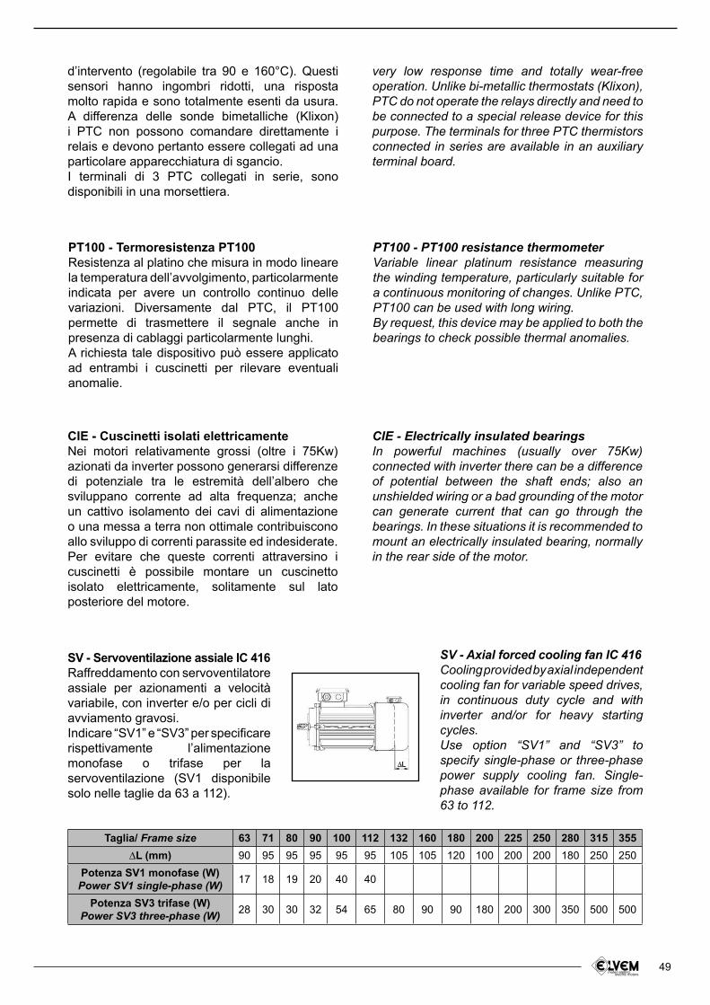
49
very low response time and totally wear-free operation. Unlike bi-metallic thermostats (Klixon), PTC do not operate the relays directly and need to be connected to a special release device for this purpose. The terminals for three PTC thermistors connected in series are available in an auxiliary terminal board.
d’intervento (regolabile tra 90 e 160°C). Questi sensori hanno ingombri ridotti, una risposta molto rapida e sono totalmente esenti da usura. A differenza delle sonde bimetalliche (Klixon) i PTC non possono comandare direttamente i relais e devono pertanto essere collegati ad una particolare apparecchiatura di sgancio.I terminali di 3 PTC collegati in serie, sono disponibili in una morsettiera.
PT100 - Termoresistenza PT100Resistenza al platino che misura in modo lineare la temperatura dell’avvolgimento, particolarmente indicata per avere un controllo continuo delle variazioni. Diversamente dal PTC, il PT100 permette di trasmettere il segnale anche in presenza di cablaggi particolarmente lunghi.A richiesta tale dispositivo può essere applicato ad entrambi i cuscinetti per rilevare eventuali anomalie.
PT100 - PT100 resistance thermometerVariable linear platinum resistance measuring the winding temperature, particularly suitable for a continuous monitoring of changes. Unlike PTC, PT100 can be used with long wiring.By request, this device may be applied to both the bearings to check possible thermal anomalies.
CIE - Cuscinetti isolati elettricamenteNei motori relativamente grossi (oltre i 75Kw) azionati da inverter possono generarsi differenze di potenziale tra le estremità dell’albero che sviluppano corrente ad alta frequenza; anche un cattivo isolamento dei cavi di alimentazione o una messa a terra non ottimale contribuiscono allo sviluppo di correnti parassite ed indesiderate. Per evitare che queste correnti attraversino i cuscinetti è possibile montare un cuscinetto isolato elettricamente, solitamente sul lato posteriore del motore.
CIE - Electrically insulated bearingsIn powerful machines (usually over 75Kw) connected with inverter there can be a difference of potential between the shaft ends; also an unshielded wiring or a bad grounding of the motor can generate current that can go through the bearings. In these situations it is recommended to mount an electrically insulated bearing, normally in the rear side of the motor.
SV - Servoventilazione assiale IC 416 Raffreddamento con servoventilatore assiale per azionamenti a velocità variabile, con inverter e/o per cicli di avviamento gravosi.Indicare “SV1” e “SV3” per speciicare rispettivamente l’alimentazione monofase o trifase per la servoventilazione (SV1 disponibile solo nelle taglie da 63 a 112).
SV - Axial forced cooling fan IC 416Cooling provided by axial independent cooling fan for variable speed drives, in continuous duty cycle and with inverter and/or for heavy starting cycles.Use option “SV1” and “SV3” to specify single-phase or three-phase power supply cooling fan. Single-phase available for frame size from 63 to 112.
Taglia/ Frame size 63 71 80 90 100 112 132 160 180 200 225 250 280 315 355
∆L (mm) 90 95 95 95 95 95 105 105 120 100 200 200 180 250 250
Potenza SV1 monofase (W)Power SV1 single-phase (W) 17 18 19 20 40 40
Potenza SV3 trifase (W)Power SV3 three-phase (W) 28 30 30 32 54 65 80 90 90 180 200 300 350 500 500
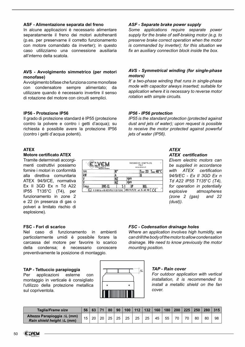
50
ASF - Alimentazione separata del frenoIn alcune applicazioni è necessario alimentare separatamente il freno dei motori autofrenanti (p.es. per preservarne il corretto funzionamento con motore comandato da inverter); in questo caso utilizziamo una connessione ausiliaria all’interno della scatola.
ASF - Separate brake power supply Some applications require separate power supply for the brake of self-braking motor (e.g. to preserve brake correct operation when the motor is commanded by inverter); for this situation we ix an auxiliary connection block inside the box.
AVS - Avvolgimento simmetrico (per motori monofase)Avvolgimento bifase che funziona come monofase con condensatore sempre alimentato; da utilizzare quando è necessario invertire il senso di rotazione del motore con circuiti semplici.
AVS - Symmetrical winding (for single-phase motors)It’ a two-phase winding that runs in single-phase mode with capacitor always inserted; suitable for application where it is necessary to reverse motor rotation with simple circuits.
IP56 - Protezione IP56Il grado di protezione standard è IP55 (protezione contro la polvere e contro i getti d’acqua); su richiesta è possibile avere la protezione IP56 (contro i getti d’acqua potenti).
IP56 - IP56 protectionIP55 is the standard protection (protected against dust and jets of water); upon request is possible to receive the motor protected against powerful jets of water (IP56).
ATEXMotore certiicato ATEXTramite determinati accorgi-menti costruttivi possiamo fornire i motori in conformità alla direttiva comunitaria ATEX 94/9/CE, normativa Ex II 3GD Ex n Td A22 IP55 T135°C (T4), per funzionamento in zone 2 e 22 (in presenza di gas o polveri a limitato rischio di esplosione).
ATEX
ATEX certiicationElvem electric motors can be supplied in accordance with ATEX certiication 94/9/EC - Ex II 3GD Ex n Td A22 IP55 T135°C (T4), for operation in potentially explosive atmospheres (zone 2 (gas) and 22 (dust)).
FSC - Fori di scaricoNel caso di funzionamento in ambienti particolarmente umidi è possibile forare la carcassa del motore per favorire lo scarico della condensa; è necessario conoscere preventivamente la posizione di montaggio.
FSC - Codensation drainage holesWhere an application involves high humidity, we can drill the body of the motor to allow condensation drainage. We need to know previously the motor mounting position.
TAP - Tettuccio parapioggiaPer applicazioni esterne con montaggio in verticale è consigliato l'utilizzo della protezione metallica sul copriventola.
TAP - Rain coverFor outdoor application with vertical installation, it is recommended to install a metallic shield on the fan cover.
∆L
Taglia/Frame size 56 63 71 80 90 100 112 132 160 180 200 225 250 280 315
Altezza Parapioggia ∆L (mm)Rain shield height ∆L (mm)
15 20 20 25 25 25 25 25 45 55 70 70 80 80 98
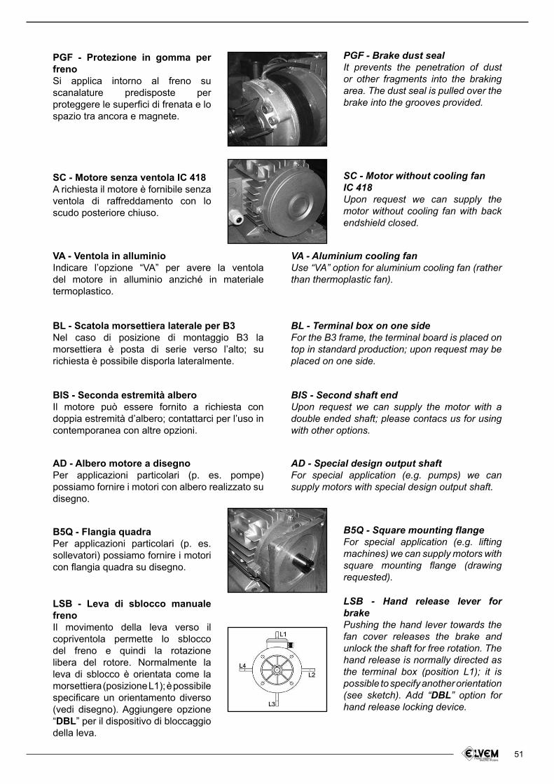
51
BL - Terminal box on one sideFor the B3 frame, the terminal board is placed on top in standard production; upon request may be placed on one side.
BL - Scatola morsettiera laterale per B3Nel caso di posizione di montaggio B3 la morsettiera è posta di serie verso l’alto; su richiesta è possibile disporla lateralmente.
BIS - Second shaft endUpon request we can supply the motor with a double ended shaft; please contacs us for using with other options.
BIS - Seconda estremità alberoIl motore può essere fornito a richiesta con doppia estremità d’albero; contattarci per l’uso in contemporanea con altre opzioni.
PGF - Protezione in gomma per frenoSi applica intorno al freno su scanalature predisposte per proteggere le superici di frenata e lo spazio tra ancora e magnete.
PGF - Brake dust sealIt prevents the penetration of dust or other fragments into the braking area. The dust seal is pulled over the brake into the grooves provided.
VA - Ventola in alluminioIndicare l’opzione “VA” per avere la ventola del motore in alluminio anziché in materiale termoplastico.
VA - Aluminium cooling fanUse “VA” option for aluminium cooling fan (rather than thermoplastic fan).
SC - Motore senza ventola IC 418A richiesta il motore è fornibile senza ventola di raffreddamento con lo scudo posteriore chiuso.
SC - Motor without cooling fanIC 418Upon request we can supply the motor without cooling fan with back endshield closed.
AD - Special design output shaftFor special application (e.g. pumps) we can supply motors with special design output shaft.
AD - Albero motore a disegnoPer applicazioni particolari (p. es. pompe) possiamo fornire i motori con albero realizzato su disegno.
LSB - Leva di sblocco manuale frenoIl movimento della leva verso il copriventola permette lo sblocco del freno e quindi la rotazione libera del rotore. Normalmente la leva di sblocco è orientata come la morsettiera (posizione L1); è possibile speciicare un orientamento diverso (vedi disegno). Aggiungere opzione “DBL” per il dispositivo di bloccaggio della leva.
B5Q - Flangia quadraPer applicazioni particolari (p. es. sollevatori) possiamo fornire i motori con langia quadra su disegno.
B5Q - Square mounting langeFor special application (e.g. lifting machines) we can supply motors with square mounting lange (drawing requested).
LSB - Hand release lever for brake
Pushing the hand lever towards the fan cover releases the brake and unlock the shaft for free rotation. The hand release is normally directed as the terminal box (position L1); it is possible to specify another orientation (see sketch). Add “DBL” option for hand release locking device.
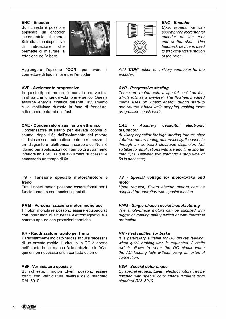
52
ENC - EncoderSu richiesta è possibile applicare un encoder incrementale sull’albero. Si tratta di un dispositivo di retroazione che permette di misurare la rotazione dell’albero.
ENC - EncoderUpon request we can assembly an incremental encoder on the rear end of the shaft. This feedback device is used to track the rotary motion of the rotor.
Aggiungere l’opzione “CON” per avere il connettore di tipo militare per l’encoder.
Add “CON” option for military connector for the encoder.
AVP - Avviamento progressivoIn questo tipo di motore è montata una ventola in ghisa che funge da volano energetico. Questa assorbe energia cinetica durante l’avviamento e la restituisce durante la fase di frenatura, rallentando entrambe le fasi.
AVP - Progressive startingThese are motors with a special cast iron fan, which acts as a lywheel. The lywheel’s added inertia uses up kinetic energy during start-up and returns it back while stopping, making more progressive shock loads.
CAE - Condensatore ausiliario elettronicoCondensatore ausiliario per elevata coppia di spunto: dopo 1,5s dall’avviamento del motore si disinserisce automaticamente per mezzo di un disgiuntore elettronico incorporato. Non è idoneo per applicazioni con tempo di avviamento inferiore ad 1,5s. Tra due avviamenti successivi è necessario un tempo di 6s.
CAE - Auxiliary capacitor electronic disjunctorAuxiliary capacitor for high starting torque: after 1,5s from motor starting, automatically disconnects through an on-board electronic disjunctor. Not suitable for applications with starting time shorter than 1,5s. Between two startings a stop time of 6s is necessary.
TS - Tensione speciale motore/motore e frenoTutti i nostri motori possono essere forniti per il funzionamento con tensioni speciali.
PMM - Personalizzazione motori monofaseI motori monofase possono essere equipaggiati con interruttori di sicurezza elettromagnetici e a camma oppure con protezioni termiche.
TS - Special voltage for motor/brake and motorUpon request, Elvem electric motors can be supplied for operation with special tension.
PMM - Single-phase special manufacturingThe single-phase motors can be supplied with trigger or rotating safety switch or with thermical protection.
RR - Raddrizzatore rapido per frenoParticolarmente indicato nei casi in cui si necessita di un arresto rapido. Il circuito in CC è aperto nell’istante in cui manca l’alimentazione in AC e quindi non necessita di un contatto esterno.
VSP- Verniciatura specialeSu richiesta, i motori Elvem possono essere forniti con verniciatura diversa dallo standard RAL 5010.
RR - Fast rectiier for brakeIt is particulary suitable for DC brakes feeding, when quick braking time is requested. A static switch allows to open the DC circuit when the AC feeding fails without using an external connection.
VSP - Special color shadeBy special request, Elvem electric motors can be inished with special color shade different from standard RAL 5010.
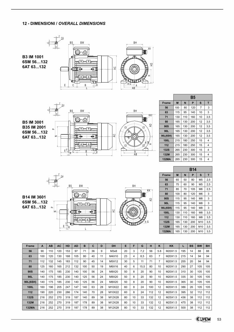
53
12 - DIMENSIONI / OVERALL DIMENSIONS
Frame A AB AC HD AD B C D DH E F G H K KK L BS BW BH
56 90 110 120 153 97 71 36 9 M3x8 20 3 7,2 56 5.8 M20X1.5 195 14 88 88
63 100 120 130 168 105 80 40 11 M4X10 23 4 8,5 63 7 M20X1.5 215 14 94 94
71 112 132 145 183 112 90 45 14 M5X12 30 5 11 71 7 M20X1.5 255 20 94 94
80 125 160 165 212 132 100 50 19 M6X16 40 6 15,5 80 10 M20X1.5 290 27 105 105
90S 140 175 185 230 140 100 56 24 M8X20 50 8 20 90 10 M20X1.5 310 30 105 105
90L 140 175 185 230 140 125 56 24 M8X20 50 8 20 90 10 M20X1.5 335 30 105 105
90L(6SH) 140 175 185 230 140 125 56 24 M8X20 50 8 20 90 10 M20X1.5 365 30 105 105
100L 160 196 205 247 147 140 63 28 M10X22 60 8 24 100 12 M20X1.5 386 26 105 105
112 190 220 230 286 174 140 70 28 M10X22 60 8 24 112 12 M25X1.5 395 32 112 112
132S 216 252 270 319 187 140 89 38 M12X28 80 10 33 132 12 M25X1.5 436 38 112 112
132M 216 252 270 319 187 178 89 38 M12X28 80 10 33 132 12 M25X1.5 475 38 112 112
132MA 216 252 270 319 187 178 89 38 M12X28 80 10 33 132 12 M25X1.5 500 38 112 112
Frame M N P S T
56 100 80 120 7 3
63 115 95 140 10 3
71 130 110 160 10 3,5
80 165 130 200 12 3,5
90S 165 130 200 12 3,5
90L 165 130 200 12 3,5
90L(6SH) 165 130 200 12 3,5
100L 215 180 250 15 4
112 215 180 250 15 4
132S 265 230 300 15 4
132M 265 230 300 15 4
132MA 265 230 300 15 4
Frame M N P S T
56 65 50 80 M5 2,5
63 75 60 90 M5 2,5
71 85 70 105 M6 2,5
80 100 80 120 M6 3
90S 115 95 140 M8 3
90L 115 95 140 M8 3
90L(6SH) 115 95 140 M8 3
100L 130 110 160 M8 3,5
112 130 110 160 M8 3,5
132S 165 130 200 M10 3,5
132M 165 130 200 M10 3,5
132MA 165 130 200 M10 3,5
B3 IM 10016SM 56…1326AT 63...132 AC
H
B H
k k
B WB S
A BA
A / 2
LBCE K
HD
B5 IM 3001B35 IM 2001 6SM 56…1326AT 63...132
4 - S HAA BLR
E T C B K
K K
B W B HB SAC
M
P
NP
AD
B14 IM 36016SM 56…1326AT 63...132
AD
N
B HB S B W
4 - S
AC
TE R L
K K
M
P
B5
B14
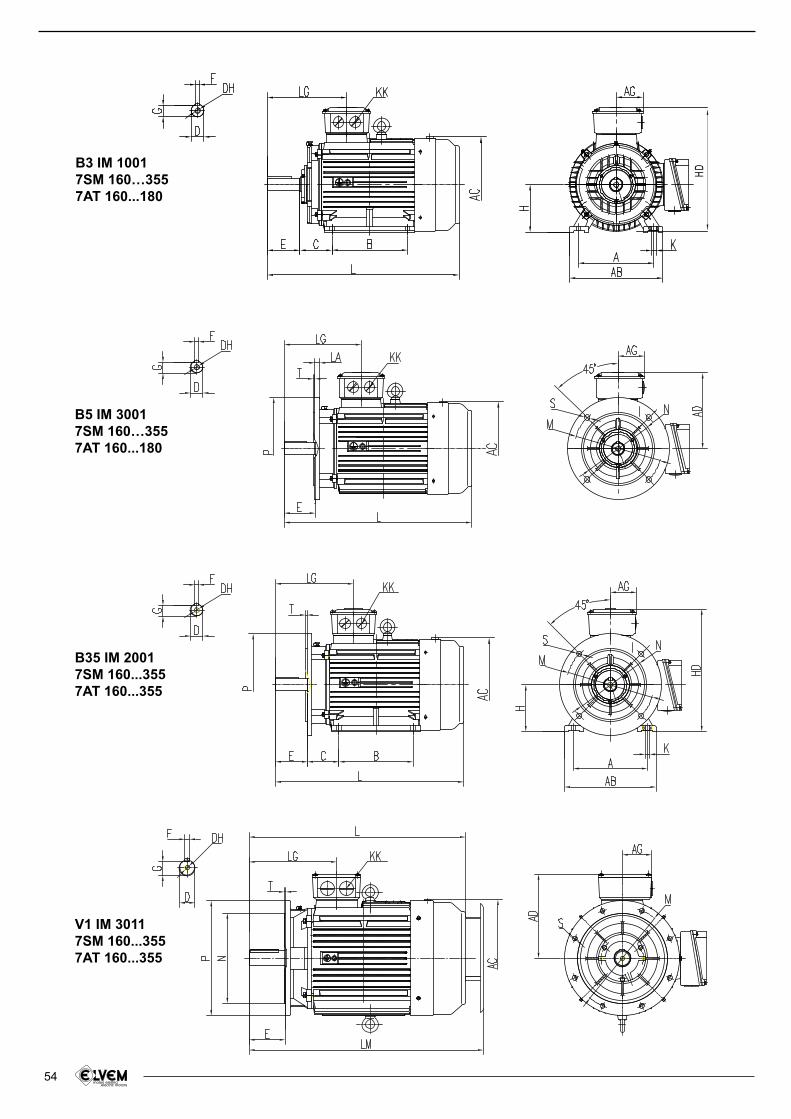
54
B3 IM 10017SM 160…3557AT 160...180
HD
B5 IM 30017SM 160…3557AT 160...180
V1 IM 30117SM 160...3557AT 160...355
B35 IM 20017SM 160...3557AT 160...355
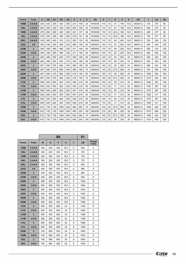
55
Frame Poles M N P S T LM Flange holes
160M 2-4-6-8 300 250 350 18,5 5 655 4
160L 2-4-6-8 300 250 350 18,5 5 700 4
180M 2-4-6-8 300 250 350 18,5 5 735 4
180L 2-4-6-8 300 250 350 18,5 5 775 4
200L 2-4-6-8 350 300 400 18,5 5 830 4
225S 4-8 400 350 450 18,5 5 895 8
225M 2 400 350 450 18,5 5 890 8
225M 4-6-8 400 350 450 18,5 5 920 8
250M 2 500 450 550 18,5 5 1005 8
250M 4-6-8 500 450 550 18,5 5 1005 8
280S 2 500 450 550 18,5 5 1040 8
280S 4-6-8 500 450 550 18,5 5 1055 8
280M 2 500 450 550 18,5 5 1080 8
280M 4-6-8 500 450 550 18,5 5 1095 8
315S 2 600 550 660 24 6 1158 8
315S 4-6-8 600 550 660 24 6 1288 8
315M 2 600 550 660 24 6 1368 8
315M 4-6-8 600 550 660 24 6 1398 8
315L 2 600 550 660 24 6 1368 8
315L 4-6-8 600 550 660 24 6 1398 8
355M 2 740 680 800 24 6 1600 8
355M 4-6-8 740 680 800 24 6 1630 8
355L 2 740 680 800 24 6 1600 8
355L 4-6-8 740 680 800 24 6 1630 8
Frame Poles A AB AC HD AD B C D DH E F G H K KK L LG AG
160M 2-4-6-8 254 320 330 425 265 210 108 42 M16X36 110 12 37 160 14,5 M32X1,5 610 270 95
160L 2-4-6-8 254 320 330 425 265 254 108 42 M16X36 110 12 37 160 14,5 M32X1,5 655 270 95
180M 2-4-6-8 279 350 380 460 280 241 121 48 M16X36 110 14 42,5 180 14,5 M32X1,5 680 277 95
180L 2-4-6-8 279 350 380 460 280 279 121 48 M16X36 110 14 42,5 180 14,5 M32X1,5 720 277 95
200L 2-4-6-8 318 395 420 515 315 305 133 55 M20X42 110 16 49 200 18,5 M40X1,5 760 300 120
225S 4-8 356 436 465 560 335 286 149 60 M20X42 140 18 53 225 18,5 M40X1,5 825 340 120
225M 2 356 436 465 560 335 311 149 55 M20X42 110 16 49 225 18,5 M40X1,5 820 310 120
225M 4-6-8 356 436 465 560 335 311 149 60 M20X42 140 18 53 225 18,5 M40X1,5 850 340 120
250M 2 406 495 520 620 375 349 168 60 M20X42 140 18 53 250 24 M50X1,5 925 353 160
250M 4-6-8 406 495 520 620 375 349 168 65 M20X42 140 18 58 250 24 M50X1,5 925 353 160
280S 2 457 550 570 685 405 368 190 65 M20X42 140 18 58 280 24 M50X1,5 960 353 160
280S 4-6-8 457 550 570 685 405 368 190 75 M20X42 140 20 67,5 280 24 M50X1,5 975 350 160
280M 2 457 550 570 685 405 419 190 65 M20X42 140 18 58 280 24 M50X1,5 1000 350 160
280M 4-6-8 457 550 570 685 405 419 190 75 M20X42 140 20 67,5 280 24 M50X1,5 1015 350 160
315S 2 508 630 650 820 500 406 216 65 M20X42 140 18 58 315 28 M63X1,5 1060 387 195
315S 4-6-8 508 630 650 820 500 406 216 80 M20X42 170 22 71 315 28 M63X1,5 1190 387 195
315M 2 508 630 650 820 500 457 216 65 M20X42 140 18 58 315 28 M63X1,5 1270 387 195
315M 4-6-8 508 630 650 820 500 457 216 80 M20X42 170 22 71 315 28 M63X1,5 1300 417 195
315L 2 508 630 650 820 500 508 216 65 M20X42 140 18 58 315 28 M63X1,5 1270 387 195
315L 4-6-8 508 630 650 820 500 508 216 80 M20X42 170 22 71 315 28 M63X1,5 1300 417 195
355M 2 610 735 735 1000 645 560 254 75 M24X50 140 20 67,5 355 28 M63X1,5 1500 420 330
355M 4-6-8 610 735 735 1000 645 560 254 100 M24X50 210 28 86 355 28 M63X1,5 1570 450 330
355L 2 610 735 735 1000 645 630 254 75 M24X50 140 20 67,5 355 28 M63X1,5 1500 420 330
355L 4-6-8 610 735 735 1000 645 630 254 100 M24X50 210 28 86 355 28 M63X1,5 1570 450 330
B5 V1
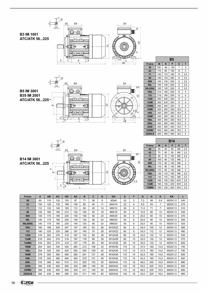
56
B3 IM 1001ATC/ATK 56...225
AC
H
B H
k k
B WB S
A BA
A / 2
LBCE K
HD
B5 IM 3001B35 IM 2001ATC/ATK 56...225
4 - S H
AA BLR
E T C B K
K K
B W B HB S
ACM
P
NP
AD
B14 IM 3601ATC/ATK 56...225 AD
N
B HB S B W
4 - S
AC
TE R L
K K
M
P
Frame A AB AC HD AD B C D DH E F G H K KK L
56 90 110 120 153 97 71 36 9 M3x8 20 3 7,2 56 5.8 M20X1.5 240
63 100 120 130 168 105 80 40 11 M4X10 23 4 8,5 63 7 M20X1.5 270
71 112 132 145 183 112 90 45 14 M5X12 30 5 11,0 71 7 M20X1.5 310
80 125 160 165 212 132 100 50 19 M6X16 40 6 15,5 80 10 M20X1.5 345
90S 140 175 185 230 140 100 56 24 M8X20 50 8 20,0 90 10 M20X1.5 370
90L 140 175 185 230 140 125 56 24 M8X20 50 8 20,0 90 10 M20X1.5 395
90L(6SH) 140 175 185 230 140 125 56 24 M8X20 50 8 20,0 90 10 M20X1.5 425
100L 160 196 205 247 147 140 63 28 M10X22 60 8 24,0 100 12 M20X1.5 460
112 190 220 230 286 187 140 70 28 M10X22 60 8 24,0 112 12 M25X1.5 480
132S 216 252 270 319 187 140 89 38 M12X28 80 10 33,0 132 12 M25X1.5 530
132M 216 252 270 319 187 178 89 38 M12X28 80 10 33,0 132 12 M25X1.5 570
132MA 216 252 270 319 187 178 89 38 M12X28 80 10 33,0 132 12 M25X1.5 600
160M 254 320 330 425 265 210 108 42 M16X36 110 12 37,0 160 14,5 M32X1,5 740
160L 254 320 330 425 265 254 108 42 M16X36 110 12 37,0 160 14,5 M32X1,5 790
180M 279 350 380 460 280 241 121 48 M16X36 110 14 42,5 180 14,5 M32X1,5 800
180L 279 350 380 460 280 279 121 48 M16X36 110 14 42,5 180 14,5 M32X1,5 850
200L 318 395 420 515 315 305 133 55 M20X42 110 16 49,0 200 18,5 M40X1,5 880
225S 356 436 465 560 335 286 149 60 M20X42 140 18 53,0 225 18,5 M40X1,5 930
225M2 356 436 465 560 335 311 149 55 M20X42 110 16 49,0 225 18,5 M40X1,5 960
225S4-8 356 436 465 560 335 311 149 60 M20X42 140 18 53,0 225 18,5 M40X1,5 960
Frame M N P S T
56 100 80 120 7 3
63 115 95 140 10 3
71 130 110 160 10 3,5
80 165 130 200 12 3,5
90S 165 130 200 12 3,5
90L 165 130 200 12 3,5
90L(6SH) 165 130 200 12 3,5
100L 215 180 250 15 4
112 215 180 250 15 4
132S 265 230 300 15 4
132M 265 230 300 15 4
132MA 265 230 300 15 4
160M 300 250 350 18,5 5
160L 300 250 350 18,5 5
180M 300 250 350 18,5 5
180L 300 250 350 18,5 5
200L 350 300 400 18,5 5
225S 400 350 450 18,5 5
225M2 400 350 450 18,5 5
225S4-8 400 350 450 18,5 5
Frame M N P S T
56 65 50 80 M5 2,5
63 75 60 90 M5 2,5
71 85 70 105 M6 2,5
80 100 80 120 M6 3
90S 115 95 140 M8 3
90L 115 95 140 M8 3
90L(6SH) 115 95 140 M8 3
100L 130 110 160 M8 3,5
112 130 110 160 M8 3,5
132S 165 130 200 M10 3,5
132M 165 130 200 M10 3,5
132MA 165 130 200 M10 3,5
B14
B5
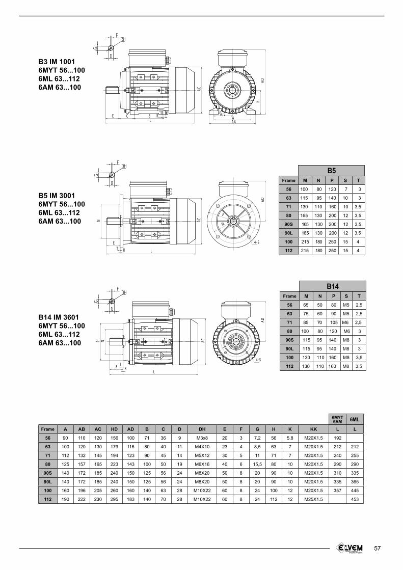
57
Frame A AB AC HD AD B C D DH E F G H K KK L L
56 90 110 120 156 100 71 36 9 M3x8 20 3 7,2 56 5.8 M20X1.5 192
63 100 120 130 179 116 80 40 11 M4X10 23 4 8,5 63 7 M20X1.5 212 212
71 112 132 145 194 123 90 45 14 M5X12 30 5 11 71 7 M20X1.5 240 255
80 125 157 165 223 143 100 50 19 M6X16 40 6 15,5 80 10 M20X1.5 290 290
90S 140 172 185 240 150 125 56 24 M8X20 50 8 20 90 10 M20X1.5 310 335
90L 140 172 185 240 150 125 56 24 M8X20 50 8 20 90 10 M20X1.5 335 365
100 160 196 205 260 160 140 63 28 M10X22 60 8 24 100 12 M20X1.5 357 445
112 190 222 230 295 183 140 70 28 M10X22 60 8 24 112 12 M25X1.5 453
Frame M N P S T
56 65 50 80 M5 2,5
63 75 60 90 M5 2,5
71 85 70 105 M6 2,5
80 100 80 120 M6 3
90S 115 95 140 M8 3
90L 115 95 140 M8 3
100 130 110 160 M8 3,5
112 130 110 160 M8 3,5
Frame M N P S T
56 100 80 120 7 3
63 115 95 140 10 3
71 130 110 160 10 3,5
80 165 130 200 12 3,5
90S 165 130 200 12 3,5
90L 165 130 200 12 3,5
100 215 180 250 15 4
112 215 180 250 15 4
6ML6MYT6AM
B3 IM 10016MYT 56...1006ML 63...1126AM 63...100
B5 IM 30016MYT 56...1006ML 63...1126AM 63...100
B14 IM 36016MYT 56...1006ML 63...1126AM 63...100
H
KBCE
L
A / 2AAA
AC
HD
L
E
R
N
T
4 - S
AD
AC
P
M
L
ET
R
N
4 - S
AC
AD
P
M
B5
B14
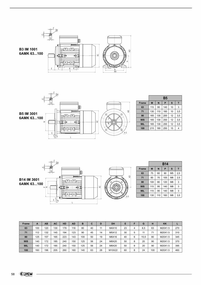
58
B3 IM 10016AMK 63...100
B5 IM 30016AMK 63...100
B14 IM 36016AMK 63...100
H
KBCE
L
A / 2AAA
AC
HD
L
E
R
N
T
4 - S
AD
AC
P
M
L
ET
R
N
4 - S
AC
AD
P
M
Frame A AB AC HD AD B C D DH E F G H KK L
63 100 120 130 179 116 80 40 11 M4X10 23 4 8,5 63 M20X1.5 270
71 112 132 145 194 123 90 45 14 M5X12 30 5 11 71 M20X1.5 310
80 125 157 165 223 143 100 50 19 M6X16 40 6 15,5 80 M20X1.5 345
90S 140 172 185 240 150 125 56 24 M8X20 50 8 20 90 M20X1.5 370
90L 140 172 185 240 150 125 56 24 M8X20 50 8 20 90 M20X1.5 395
100 160 196 205 260 160 140 63 28 M10X22 60 8 24 100 M20X1.5 460
Frame M N P S T
63 115 95 140 10 3
71 130 110 160 10 3,5
80 165 130 200 12 3,5
90S 165 130 200 12 3,5
90L 165 130 200 12 3,5
100 215 180 250 15 4
Frame M N P S T
63 75 60 90 M5 2,5
71 85 70 105 M6 2,5
80 100 80 120 M6 3
90S 115 95 140 M8 3
90L 115 95 140 M8 3
100 130 110 160 M8 3,5
B5
B14
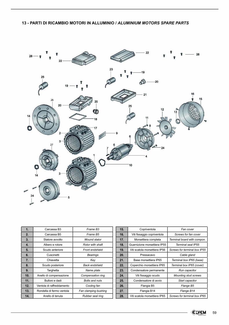
59
13 - PARTI DI RICAMBIO MOTORI IN ALLUMINIO / ALUMINIUM MOTORS SPARE PARTS
1. Carcassa B3 Frame B3
2. Carcassa B5 Frame B5
3. Statore avvolto Wound stator
4. Albero e rotore Rotor with shaft
5. Scudo anteriore Front endshield
6. Cuscinetti Bearings
7. Chiavetta Key
8. Scudo posteriore Back endshield
9. Targhetta Name plate
10. Anello di compensazione Compensation ring
11. Bulloni e dadi Bolts and nuts
12. Ventola di raffreddamento Cooling fan
13. Rondella di fermo ventola Fan clamping bushing
14. Anello di tenuta Rubber seal ring
15. Copriventola Fan cover
16. Viti fissaggio copriventola Screws for fan cover
17. Morsettiera completa Terminal board with compon.
18. Guarnizione morsettiera IP55 Terminal seal IP55
19. Viti scatola morsettiera IP56 Screws for terminal box IP55
20. Pressacavo Cable gland
21. Base morsettiera IP65 Terminal box IP65 (base)
22. Coperchio morsettiera IP65 Terminal box IP65 (cover)
23. Condensatore permanente Run capacitor
24. Viti issaggio scudo Mounting stud screws
25. Condensatore di avvio Start capacitor
26. Flangia B5 Flange B5
27. Flangia B14 Flange B14
28. Viti scatola morsettiera IP65 Screws for terminal box IP65
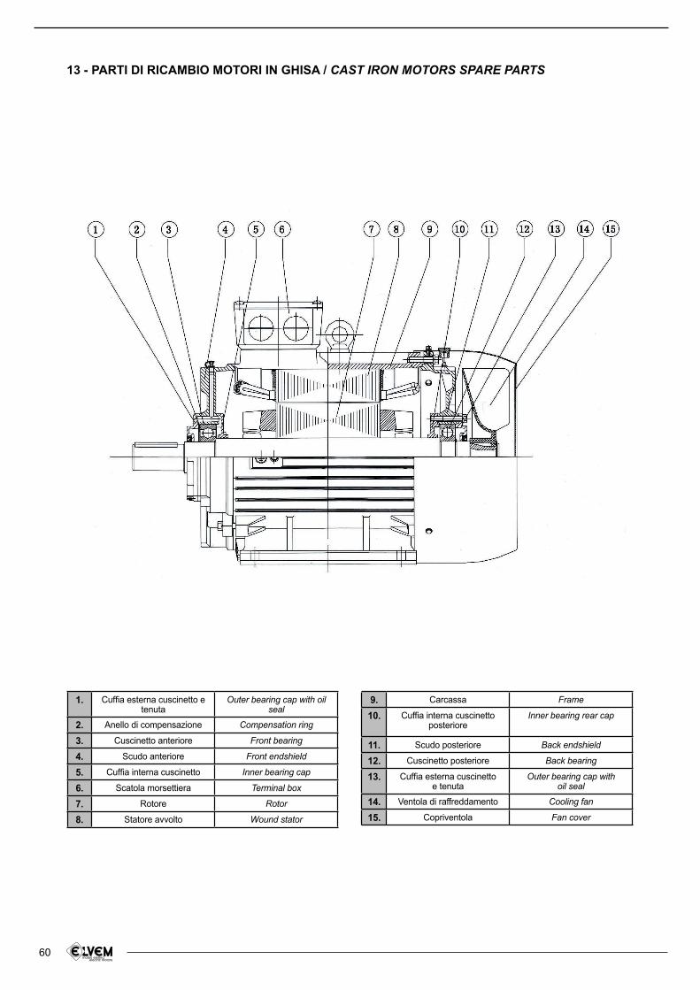
60
13 - PARTI DI RICAMBIO MOTORI IN GHISA / CAST IRON MOTORS SPARE PARTS
1. Cufia esterna cuscinetto e tenuta
Outer bearing cap with oil seal
2. Anello di compensazione Compensation ring
3. Cuscinetto anteriore Front bearing
4. Scudo anteriore Front endshield
5. Cufia interna cuscinetto Inner bearing cap
6. Scatola morsettiera Terminal box
7. Rotore Rotor
8. Statore avvolto Wound stator
9. Carcassa Frame
10. Cuffia interna cuscinetto posteriore
Inner bearing rear cap
11. Scudo posteriore Back endshield
12. Cuscinetto posteriore Back bearing
13. Cufia esterna cuscinettoe tenuta
Outer bearing cap withoil seal
14. Ventola di raffreddamento Cooling fan
15. Copriventola Fan cover
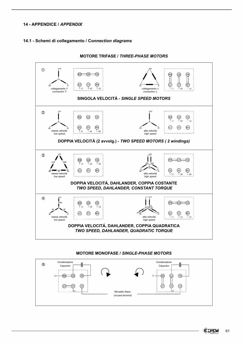
61
14 - APPENDICE / APPENDIX
14.1 - Schemi di collegamento / Connection diagrams
SINGOLA VELOCITÁ - SINGLE SPEED MOTORS
collegamento Yconnection Y
bassa velocitàlow speed
bassa velocitàlow speed
bassa velocitàlow speed
Morsetto liberoUnused terminal
Condensatore
Capacitor
Condensatore
Capacitor
collegamento ∆connection ∆
alta velocitàhigh speed
alta velocitàhigh speed
alta velocitàhigh speed
DOPPIA VELOCITÁ (2 avvolg.) - TWO SPEED MOTORS ( 2 windings)
DOPPIA VELOCITÁ, DAHLANDER, COPPIA COSTANTETWO SPEED, DAHLANDER, CONSTANT TORQUE
DOPPIA VELOCITÁ, DAHLANDER, COPPIA QUADRATICATWO SPEED, DAHLANDER, QUADRATIC TORQUE
MOTORE MONOFASE / SINGLE-PHASE MOTORS
MOTORE TRIFASE / THREE-PHASE MOTORS
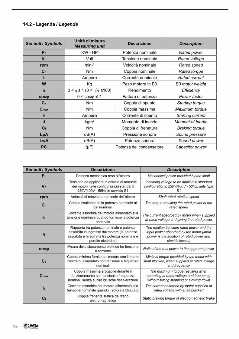
62
Simboli / Symbols Unità di misuraMeasuring unit Descrizione Description
Pn KW - HP Potenza nominale Rated power
Vn Volt Tensione nominale Rated voltage
rpm min-¹ Velocità nominale Rated speed
Cn Nm Coppia nominale Rated torqueIn Ampere Corrente nominale Rated current
W Kg Peso motore in B3 B3 motor weightさ 0 < さ ≤ 1 (0 < さ% ≤100) Rendimento Eficiency
cosl 0 < cosl ≤ 1 Fattore di potenza Power factorCs Nm Coppia di spunto Starting torque
Cmax Nm Coppia massima Maximum torqueIs Ampere Corrente di spunto Starting current
J kgm² Momento di inerzia Moment of InertiaCf Nm Coppia di frenatura Braking torque
LpA dB(A) Pressione sonora Sound pressure
LwA dB(A) Potenza sonora Sound power
PC (たF) Potenza del condensatore Capacitor power
Simboli / Symbols Descrizione DescriptionPn Potenza meccanica resa all'albero Mechanical power provided by the shaft
Vn
Tensione da applicare in entrata ai morsetti dei motori nelle conigurazioni standard
230V/400V - 50Hz in servizio S1
Incoming voltage to be applied in standard conigurations: 230V/400V - 50Hz, duty type
S1
rpm Velocità di rotazione nominale dell'albero Shaft rated rotation speed
CnCoppia risultante dalla potenza nominale ai
giri nominaliThe torque resulting the rated power at the
rated speed
InCorrente assorbita dal motore alimentato alla tensione nominale quando fornisce la potenza
nominale
The current absorbed by motor when supplied at rated voltage and giving the rated power
さ
Rapporto tra potenza nominale e potenza assorbita in ingresso dal motore (la potenza
assorbita è la somma tra potenza nominale e perdite elettriche)
The relation between rated power and the input power absorbed by the motor (input power is the addition of rated power and
electric losses)
cosl Misura della sfasamento elettrico tra tensione e corrente
Ratio of the real power to the apparent power
Cs
Coppia minima fornita dal motore con il rotore bloccato, alimentato con tensione e fequenza
nominali
Minimal torque provided by the motor with shaft blocked, when supplied at rated voltage
and frequency
Cmax
Coppia massima erogabile durante il funzionamento con tensioni e frequenza
nominali senza subire brusche decelerazioni
The maximum torque resulting when operating at rated voltage and frequency, without strong stopping or slowing down
IsCorrente assorbita dal motore alimentato alla tensione nominale quando il rotore è bloccato
The current absorbed by motor supplied at rated voltage with shaft blocked
CfCoppia frenante statica del freno
elettromagneticoStatic braking torque of electromagnetic brake
14.2 - Legenda / Legenda
63
14.3 - Condizioni generali di fornitura
Le offerte di vendita sono valide per 30 giorni salva diversa scadenza indicata nell’offerta stessa.
Gli ordini sono validi e vincolanti per Elvem solo se pervenuti per iscritto (via posta, fax o e-mail) e confermati per iscritto da parte di Elvem.
I prezzi concordati al momento dell’ordine si considerano sempre al netto dell’IVA. Sono esclusi inoltre i costi di imballaggio, di spedizione e qualsiasi altra spesa aggiuntiva.
Nel caso l’acquirente riiuti la fornitura del materiale ordinato, sarà tenuto comunque al pagamento del 20% dell’importo totale dell’ordine per quanto riguarda i prodotti di serie presenti nel catalogo, escluse le lavorazioni speciali. Riiutando la fornitura di articoli speciali o realizzati su disegno, l’acquirente sarà tenuto al pagamento del totale dell’importo dovuto.
La garanzia ha validità di 1 (uno) anno dall’emissione della fattura di vendita del prodotto. Essa copre solo la riparazione o sostituzione del prodotto o delle parti difettose fornite da Elvem, qualora i difetti siano imputabili al processo di produzione. I resi di materiale saranno accettati solo se i costi relativi ai trasporti saranno coperti dal cliente. La nostra garanzia non interviene in caso di difetti o malfunzionamenti attribuiti a fattori esterni quali scarsa manutenzione, sovraccarichi, scarsa lubriicazione, errata selezione o errato montaggio del prodotto.
I pagamenti devono essere effettuati entro i termini stabiliti in fase di ordine e sono ritenuti validi solo se effettuati presso la sede di Elvem. Non sono ammessi ritardi, sospensioni o pagamenti parziali dell’importo dovuto; in caso di inadempienze, Elvem si riserva di sospendere qualsiasi ulteriore fornitura e di addebitare all’inadempiente tutti i costi aggiuntivi derivati. In caso di controversie, è competente il foro di Bassano del Grappa.
Non si accettano resi di materiale se non preventivamente autorizzati per iscritto dal nostro uficio commerciale.
Questa pubblicazione annulla e sostituisce tutte le precedenti. I dati contenuti in questo catalogo sono indicativi e passibili di modiica senza preavviso.
14.3 - Terms and conditions of sale
Sale offers are valid for 30 days unless otherwise speciied in the offer.
Orders are valid and binding for Elvem only if effected in writing (send via mail, fax or e-mail) and conirmed in writing by Elvem.
Prices stated in order conirmation do not include VAT. They do not include also packaging, shipment or any other additional cost.
If the purchaser refuses the delivery of standard products, he has to pay a sum of 20% of total amount of the order. Refusing non-standard goods (e.g. special designed items), 100% of the amount must be paid.
Our warranty expires after 1 (one) year from invoice date of the product. It only covers the replacement or repair free of charge of the defective items or parts furnished by Elvem, when faults are to be ascribed to manufacturing processes. Return of material will only be accepted if transport charges will be covered by the customer. Our guarantee does not cover defects or faults which would be attributed to external factors, insuficient maintenance, overload, inadequate lubrication, improper selection, mounting errors.
Payments must be paid by the agreed dates
and are only considered valid if they are made to Elvem head ofice. No suspension, delay or partial payment of the due amount will be admitted; in case of breach of payment terms, Elvem reserves the right to suspend the supply
of all further goods and to charge all resulting damages and additional costs to the customer. In case of controversies, the competent jurisdiction is Bassano del Grappa law court.
No returns of material will be accepted
unless previously authorized in writing from our customer ofice.
This catalogue cancels and replaces every
previous edition. The data indicated in this catalogue are simply general information. Data may be changed without any notice.