9.5 infiltration basins
TRANSCRIPT
New Jersey Stormwater Best Management Practices Manual Updated February 2016 Chapter 9.5 Infiltration Basins Page 1
9.5 INFILTRATION BASINS
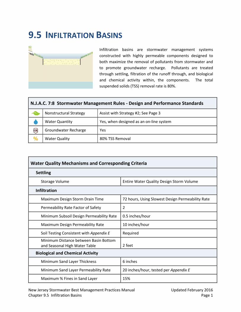
Infiltration basins are stormwater management systems
constructed with highly permeable components designed to
both maximize the removal of pollutants from stormwater and
to promote groundwater recharge. Pollutants are treated
through settling, filtration of the runoff through, and biological
and chemical activity within, the components. The total
suspended solids (TSS) removal rate is 80%.
N.J.A.C. 7:8 Stormwater Management Rules - Design and Performance Standards
Nonstructural Strategy Assist with Strategy #2; See Page 3
Water Quantity Yes, when designed as an on-line system
Groundwater Recharge Yes
Water Quality 80% TSS Removal
Water Quality Mechanisms and Corresponding Criteria
Settling
Storage Volume Entire Water Quality Design Storm Volume
Infiltration
Maximum Design Storm Drain Time 72 hours, Using Slowest Design Permeability Rate
Permeability Rate Factor of Safety 2
Minimum Subsoil Design Permeability Rate 0.5 inches/hour
Maximum Design Permeability Rate 10 inches/hour
Soil Testing Consistent with Appendix E Required
Minimum Distance between Basin Bottom and Seasonal High Water Table 2 feet
Biological and Chemical Activity
Minimum Sand Layer Thickness 6 inches
Minimum Sand Layer Permeability Rate 20 inches/hour, tested per Appendix E
Maximum % Fines in Sand Layer 15%

New Jersey Stormwater Best Management Practices Manual Updated February 2016 Chapter 9.5 Infiltration Basins Page 2
Introduction
Infiltration basins are stormwater management systems constructed in areas of highly permeable soil that provide temporary storage of stormwater runoff and can help to reduce increases in both the peak rate and total volume of runoff caused by land development. Pollutants in runoff are treated through the processes of filtration through and biological and chemical activity within the soil.
In these systems, the rate of infiltration is affected by the permeability rate of the underlying soil, the distance separating the lowest basin elevation from the seasonal high water table (SHWT) and the area of the basin bottom. While loss of subsoil permeability through soil compaction is a concern, transport of dissolved pollutants by highly permeable subsoil is of equal concern; therefore, care must be taken when using fertilizers and herbicides upgradient of an infiltration basin.
Additionally, due to the potential for groundwater contamination, the use of infiltration basins, and all stormwater infiltration best management practices (BMPs), is prohibited in areas where high pollutant or sediment loading is anticipated. For more information regarding stormwater runoff that may not be infiltrated, refer to N.J.A.C. 7:8-5.4(a)2.iii. However, this prohibition is limited only to areas onsite where this type of loading is expected. Additionally, infiltration basins may only be used on these types of sites provided the location of the infiltration basin is not inconsistent with a remedial action work plan or landfill closure plan. Discharge from infiltration basins of the smaller storm events occurs through the subsoil; therefore, they may not be used where their installation would create a significant risk of adverse hydraulic impacts. These impacts may include exacerbating a naturally or seasonally high water table so as to cause surficial ponding, flooding of basements, or interference with the proper operation of a subsurface sewage disposal system or other subsurface structure, or where their construction will compact the subsoil. Hydraulic impacts on the groundwater table must be assessed. For more information on groundwater mounding analysis, refer to the USGS Paper on Assessment of Impacts link on the Additional Guidance Documents page at www.njstormwater.org.
Finally, an infiltration basin must have a maintenance plan and, if privately owned, must be protected by easement, deed restriction, ordinance, or other legal measures that prevent its neglect, adverse alteration, or removal.
New Jersey Stormwater Best Management Practices Manual Updated February 2016 Chapter 9.5 Infiltration Basins Page 3
Applications
The use of infiltration basins is applicable only where the soils have the required permeability rate identified in the Design Criteria section found below.
The nonstructural stormwater management strategies design standard in the Stormwater Management rules must be addressed for all major development, pursuant to N.J.A.C. 7:8-5.3(a). The site evaluation for nonstructural strategies should consider all nine strategies. When used close to the source of stormwater runoff, the design of a surface or subsurface infiltration basin can assist in maximizing the following strategy:
Strategy #2: The minimization of impervious surfaces and breaking up or disconnection of the flow of runoff over impervious surfaces.
Infiltration basins may be designed to reduce peak runoff rates when designed as an on-line system in combination with an extended detention basin; however, regardless of the design storm chosen, all infiltration basins must be designed for stability and in accordance with the Standards for Soil Erosion and Sediment Control in New Jersey.
Infiltration basins may be used to meet the groundwater recharge requirements of the Stormwater Management rules found at N.J.A.C. 7:8. For more information on computing groundwater recharge, see Chapter 6: Groundwater Recharge.
To receive credit for a TSS removal rate of 80%, infiltration basins must be designed to treat the Water Quality Design Storm and in accordance with all of the following criteria.
Design Criteria
Basic Requirements
An infiltration basin may be designed as a surface or subsurface system. The following criteria apply to both configurations. Design criteria specific to surface infiltration basins may be found beginning on page 10; design criteria specific to subsurface infiltration basins may be found beginning on page 12. Additional requirements for the extended detention option may be found beginning on page 6.
Inflow
All inflow must be stable and non-erosive and must be consistent with the applicable subchapters of the Standards for Soil Erosion and Sediment Control in New Jersey, such as the Standard for Conduit Outlet Protection.
Storage Volume
Infiltration basins may be constructed as either off-line or on-line systems. In off-line systems, most, or all, of the runoff from storms larger than the Water Quality Design Storm bypass the
New Jersey Stormwater Best Management Practices Manual Updated February 2016 Chapter 9.5 Infiltration Basins Page 4
infiltration basin through an upgradient diversion; this reduces the size of the required basin storage volume, the system’s long-term pollutant loading and associated maintenance. On-line systems receive runoff from all storms events; they provide treatment for the Water Quality Design Storm, and they convey the runoff from larger storms through an overflow. These on-line systems store and attenuate the larger storm events and provide runoff quantity control; in such systems, the invert of the lowest quantity control outlet is set at the water surface elevation of the Water Quality Design Storm.
The maximum design volume to be infiltrated is the volume generated by the Water Quality Design Storm.
The system must have sufficient storage volume to contain the Water Quality Design Storm runoff volume without overflow.
Infiltration may not be included in routing calculations for quantity control. Infiltration is defined as any discharge of runoff from the system into the subsoil and is sometimes referred to as exfiltration.
No standing water may remain in an infiltration basin 72 hours after a rain event in order to allow for sufficient storage for the next rain event. Additionally, storage in excess of 72 hours may render the basin ineffective and may result in anaerobic conditions, odor, and both water quality and mosquito breeding issues.
Geometry
Infiltration basins may not be constructed in areas where the surrounding slopes are 15% or greater.
The area of the basin intended for infiltration must be as level as possible in order to uniformly distribute runoff infiltration over the subsoil.
The SHWT or bedrock must be at least 2 feet below the lowest extent of the basin bottom. In surface basins, this distance is measured from the bottom of the sand layer.
Permeability Rates
The use of infiltration basins for stormwater management is only feasible where the subsoil is sufficiently permeable to meet the minimum permeability rate below.
Soil tests are required at the exact location of the proposed basin in order to confirm its ability to function as designed. A minimum of two soil profile pits are required within the infiltration area of any proposed infiltration basin. Take note that permits may be required for soil testing in regulated areas, such as areas regulated under the Flood Hazard Area Control Act Rules (N.J.A.C. 7:13), the Freshwater Wetlands Protection Act Rules (N.J.A.C. 7:7A), the Coastal Zone Management Rules (N.J.A.C. 7:7), and the Highlands Water Protection and Planning Rules (N.J.A.C. 7:38).
The testing of all permeability rates must be consistent with Appendix E: Soil Testing Criteria in this manual, including the required information to be included in the soil logs, which can be found in section 3.b Soil Logs. In accordance with N.J.A.C. 7:9A-6.2(j)1, Standards for Individual
New Jersey Stormwater Best Management Practices Manual Updated February 2016 Chapter 9.5 Infiltration Basins Page 5
Subsurface Sewage Disposal Systems, the slowest tested permeability must be used for design purposes.
Since the actual permeability rate may vary from soil testing results and may decrease over time, a factor of safety of 2 must be applied to the slowest tested permeability rate to determine the design permeability rate. The design permeability rate would then be used to compute the basin’s drain time for the maximum design volume. The drain time is defined as the time it takes to fully infiltrate the maximum design storm runoff volume through the most hydraulically restrictive layer.
The maximum design permeability rate is 10 inches/hour for any tested permeability rate of 20 inches/hour or more.
The minimum design permeability rate of the subsoil is 0.5 inches/hour, which equates to a minimum tested permeability rate of 1.0 inch/hour.
As with any infiltration BMP, groundwater mounding impacts must be assessed, as required by N.J.A.C. 7:8-5.4(a)2.iv. This includes an analysis of the reduction in permeability rate when groundwater mounding is present. Where the mounding analysis identifies adverse impacts, the infiltration basin shall be redesigned or relocated, as appropriate. The mounding analysis shall provide details and supporting documentation on the methods used and assumptions made, including values used in calculations.
Safety
All infiltration basins must be designed to safely convey overflows to downstream drainage systems. The design of any overflow structure must be sufficient to provide safe, stable discharge of stormwater in the event of an overflow. Safe and stable discharge minimizes the possibility of adverse impacts, including erosion and flooding in down-gradient areas. Therefore, discharge in the event of an overflow must be consistent with the Standards for Off-Site Stability found in the Standards for Soil Erosion and Sediment Control in New Jersey.
Infiltration basins that are classified as dams under the NJDEP Dam Safety Standards at N.J.A.C. 7:20 must meet the overflow requirements under these regulations. Overflow capacity can be provided by a hydraulic structure, such as a weir or orifice, or a surface feature, such as a swale or open channel.
Construction Requirements
During clearing and grading of the site, measures must be taken to eliminate soil compaction at the location of a proposed infiltration basin.
The location of the proposed infiltration basin must be cordoned off during construction to prevent compaction of the subsoil by construction equipment or stockpiles.
The use of the location proposed for an infiltration basin to provide sediment control during construction is discouraged; however, when unavoidable, excavation for the sediment control basin must be at least 2 feet above the final design elevation of the basin bottom.
New Jersey Stormwater Best Management Practices Manual Updated February 2016 Chapter 9.5 Infiltration Basins Page 6
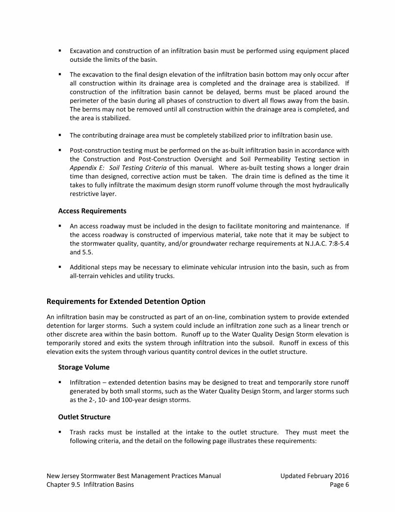
Excavation and construction of an infiltration basin must be performed using equipment placed outside the limits of the basin.
The excavation to the final design elevation of the infiltration basin bottom may only occur after all construction within its drainage area is completed and the drainage area is stabilized. If construction of the infiltration basin cannot be delayed, berms must be placed around the perimeter of the basin during all phases of construction to divert all flows away from the basin. The berms may not be removed until all construction within the drainage area is completed, and the area is stabilized.
The contributing drainage area must be completely stabilized prior to infiltration basin use.
Post-construction testing must be performed on the as-built infiltration basin in accordance with the Construction and Post-Construction Oversight and Soil Permeability Testing section in Appendix E: Soil Testing Criteria of this manual. Where as-built testing shows a longer drain time than designed, corrective action must be taken. The drain time is defined as the time it takes to fully infiltrate the maximum design storm runoff volume through the most hydraulically restrictive layer.
Access Requirements
An access roadway must be included in the design to facilitate monitoring and maintenance. If the access roadway is constructed of impervious material, take note that it may be subject to the stormwater quality, quantity, and/or groundwater recharge requirements at N.J.A.C. 7:8-5.4 and 5.5.
Additional steps may be necessary to eliminate vehicular intrusion into the basin, such as from all-terrain vehicles and utility trucks.
Requirements for Extended Detention Option
An infiltration basin may be constructed as part of an on-line, combination system to provide extended detention for larger storms. Such a system could include an infiltration zone such as a linear trench or other discrete area within the basin bottom. Runoff up to the Water Quality Design Storm elevation is temporarily stored and exits the system through infiltration into the subsoil. Runoff in excess of this elevation exits the system through various quantity control devices in the outlet structure.
Storage Volume
Infiltration – extended detention basins may be designed to treat and temporarily store runoff generated by both small storms, such as the Water Quality Design Storm, and larger storms such as the 2-, 10- and 100-year design storms.
Outlet Structure
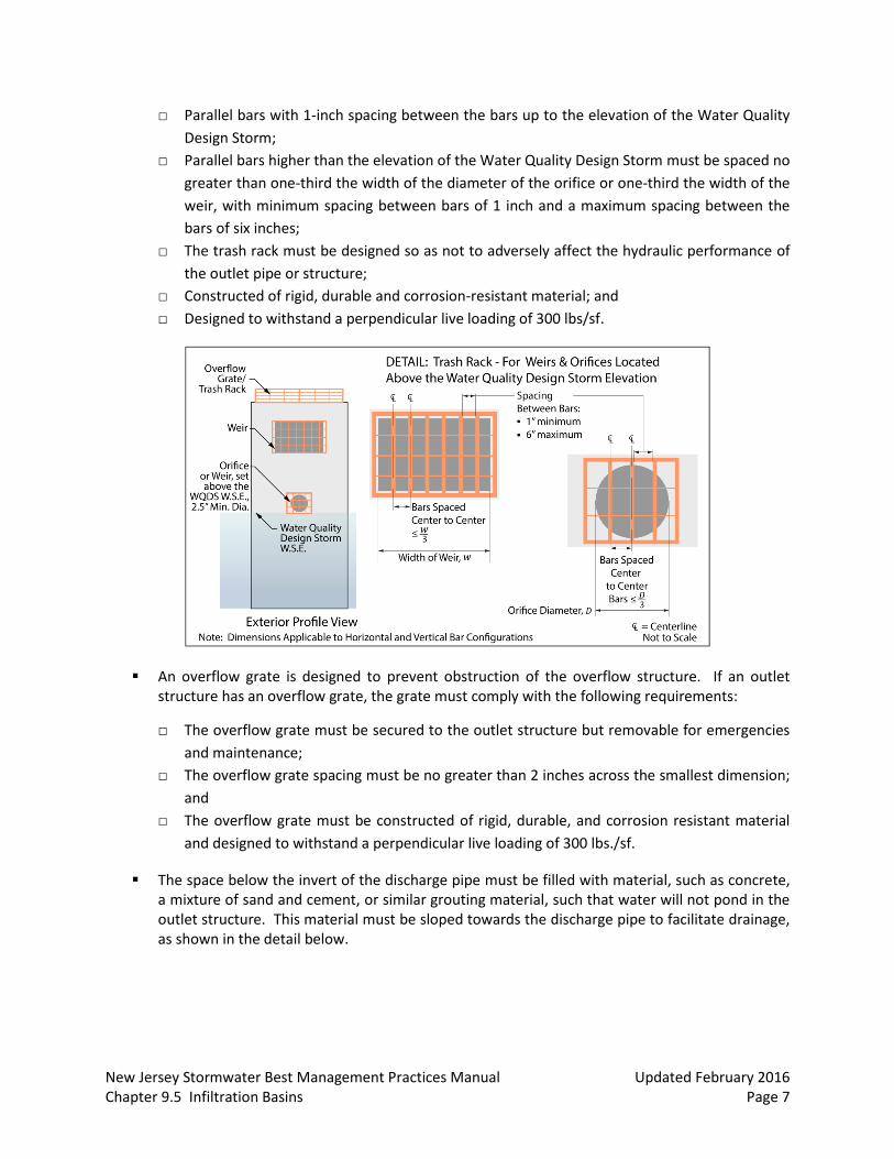
Trash racks must be installed at the intake to the outlet structure. They must meet the following criteria, and the detail on the following page illustrates these requirements:
New Jersey Stormwater Best Management Practices Manual Updated February 2016 Chapter 9.5 Infiltration Basins Page 7
□ Parallel bars with 1-inch spacing between the bars up to the elevation of the Water Quality
Design Storm;
□ Parallel bars higher than the elevation of the Water Quality Design Storm must be spaced no
greater than one-third the width of the diameter of the orifice or one-third the width of the
weir, with minimum spacing between bars of 1 inch and a maximum spacing between the
bars of six inches;
□ The trash rack must be designed so as not to adversely affect the hydraulic performance of
the outlet pipe or structure;
□ Constructed of rigid, durable and corrosion-resistant material; and
□ Designed to withstand a perpendicular live loading of 300 lbs/sf.
An overflow grate is designed to prevent obstruction of the overflow structure. If an outlet structure has an overflow grate, the grate must comply with the following requirements:
□ The overflow grate must be secured to the outlet structure but removable for emergencies
and maintenance;
□ The overflow grate spacing must be no greater than 2 inches across the smallest dimension;
and
□ The overflow grate must be constructed of rigid, durable, and corrosion resistant material
and designed to withstand a perpendicular live loading of 300 lbs./sf.
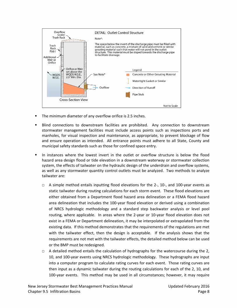
The space below the invert of the discharge pipe must be filled with material, such as concrete, a mixture of sand and cement, or similar grouting material, such that water will not pond in the outlet structure. This material must be sloped towards the discharge pipe to facilitate drainage, as shown in the detail below.
New Jersey Stormwater Best Management Practices Manual Updated February 2016 Chapter 9.5 Infiltration Basins Page 8
The minimum diameter of any overflow orifice is 2.5 inches.
Blind connections to downstream facilities are prohibited. Any connection to downstream stormwater management facilities must include access points such as inspections ports and manholes, for visual inspection and maintenance, as appropriate, to prevent blockage of flow and ensure operation as intended. All entrance points must adhere to all State, County and municipal safety standards such as those for confined space entry.
In instances where the lowest invert in the outlet or overflow structure is below the flood hazard area design flood or tide elevation in a downstream waterway or stormwater collection system, the effects of tailwater on the hydraulic design of the underdrain and overflow systems, as well as any stormwater quantity control outlets must be analyzed. Two methods to analyze tailwater are:
□ A simple method entails inputting flood elevations for the 2-, 10-, and 100-year events as
static tailwater during routing calculations for each storm event. These flood elevations are
either obtained from a Department flood hazard area delineation or a FEMA flood hazard
area delineation that includes the 100-year flood elevation or derived using a combination
of NRCS hydrologic methodology and a standard step backwater analysis or level pool
routing, where applicable. In areas where the 2-year or 10-year flood elevation does not
exist in a FEMA or Department delineation, it may be interpolated or extrapolated from the
existing data. If this method demonstrates that the requirements of the regulations are met
with the tailwater effect, then the design is acceptable. If the analysis shows that the
requirements are not met with the tailwater effects, the detailed method below can be used
or the BMP must be redesigned.
□ A detailed method entails the calculation of hydrographs for the watercourse during the 2,
10, and 100-year events using NRCS hydrologic methodology. These hydrographs are input
into a computer program to calculate rating curves for each event. Those rating curves are
then input as a dynamic tailwater during the routing calculations for each of the 2, 10, and
100-year events. This method may be used in all circumstances; however, it may require
New Jersey Stormwater Best Management Practices Manual Updated February 2016 Chapter 9.5 Infiltration Basins Page 9
more advanced computer programs. If this method demonstrates that the requirements of
the regulations are met with the tailwater effect, then the design is acceptable. If the
analysis shows that the requirements are not met with the tailwater effects, the BMP must
be redesigned.
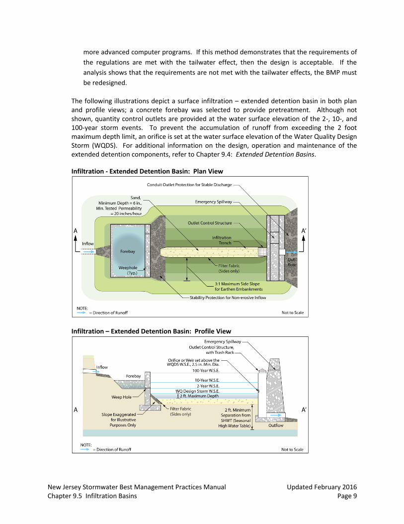
The following illustrations depict a surface infiltration – extended detention basin in both plan and profile views; a concrete forebay was selected to provide pretreatment. Although not shown, quantity control outlets are provided at the water surface elevation of the 2-, 10-, and 100-year storm events. To prevent the accumulation of runoff from exceeding the 2 foot maximum depth limit, an orifice is set at the water surface elevation of the Water Quality Design Storm (WQDS). For additional information on the design, operation and maintenance of the extended detention components, refer to Chapter 9.4: Extended Detention Basins.
Infiltration - Extended Detention Basin: Plan View
Infiltration – Extended Detention Basin: Profile View
New Jersey Stormwater Best Management Practices Manual Updated February 2016 Chapter 9.5 Infiltration Basins Page 10
Types of Infiltration Basins
There are two types of infiltration basins:
1. Surface Infiltration Basins 2. Subsurface Infiltration Basins
Individual Types of Infiltration Basins
The following section provides detailed design criteria for each type of infiltration basin. The illustrations depict possible configurations and flow paths and are not intended to limit the design.
Surface Infiltration Basins
Geometry
The maximum interior slope for an earthen dam, embankment or berm is 3:1.
The vertical distance between the basin bottom and the Water Quality Design Storm Water surface elevation must be no greater than 2 feet.
Sand Layer
To ensure that the design permeability rate is maintained over time, a sand layer is required at the bottom of every surface type infiltration basin.
The minimum depth is 6 inches.
The sand must meet all the specifications for clean, medium-aggregate concrete sand in accordance with AASHTO M-6 or ASTM C-33, as certified by a professional engineer licensed in the State of New Jersey.
The maximum percentage of fines is 15%.
The minimum tested permeability rate is 20 inches/hour.
The use of top soil and vegetation is prohibited. If a vegetated BMP is desired, refer to Chapter 9.1: Bioretention Systems.
Filter fabric is required along the sides of the infiltration basin to prevent the migration of fine particles from the surrounding soil; filter fabric may not be used along the bottom of the basin because it may result in a loss of permeability.
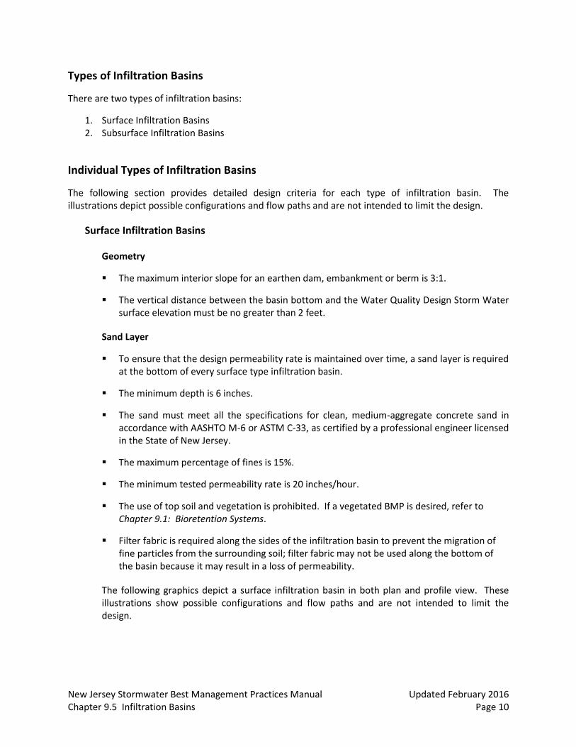
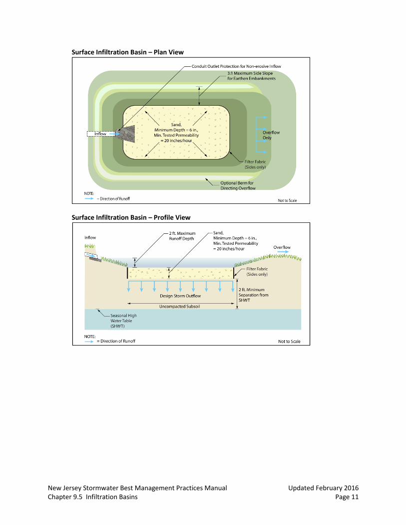
The following graphics depict a surface infiltration basin in both plan and profile view. These illustrations show possible configurations and flow paths and are not intended to limit the design.
New Jersey Stormwater Best Management Practices Manual Updated February 2016 Chapter 9.5 Infiltration Basins Page 11
Surface Infiltration Basin – Plan View
Surface Infiltration Basin – Profile View
New Jersey Stormwater Best Management Practices Manual Updated February 2016 Chapter 9.5 Infiltration Basins Page 12
Subsurface Infiltration Basins
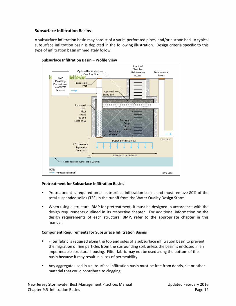
A subsurface infiltration basin may consist of a vault, perforated pipes, and/or a stone bed. A typical subsurface infiltration basin is depicted in the following illustration. Design criteria specific to this type of infiltration basin immediately follow.
Subsurface Infiltration Basin – Profile View
Pretreatment for Subsurface Infiltration Basins
Pretreatment is required on all subsurface infiltration basins and must remove 80% of the total suspended solids (TSS) in the runoff from the Water Quality Design Storm.
When using a structural BMP for pretreatment, it must be designed in accordance with the design requirements outlined in its respective chapter. For additional information on the design requirements of each structural BMP, refer to the appropriate chapter in this manual.
Component Requirements for Subsurface Infiltration Basins
Filter fabric is required along the top and sides of a subsurface infiltration basin to prevent the migration of fine particles from the surrounding soil, unless the basin is enclosed in an impermeable structural housing. Filter fabric may not be used along the bottom of the basin because it may result in a loss of permeability.
Any aggregate used in a subsurface infiltration basin must be free from debris, silt or other material that could contribute to clogging.
New Jersey Stormwater Best Management Practices Manual Updated February 2016 Chapter 9.5 Infiltration Basins Page 13
Access Requirements
At least one inspection port that extends into the subsoil must be provided in the area of the infiltration basin to monitor the functionality of the basin. The location of the inspection port must be shown in the maintenance plan. Additionally, the maximum design storm depth of runoff must be marked on the structure and its level included in the design report and maintenance plan.
All points of access must also be covered in such a way as to prevent sediment or other material from entering the system and to prevent the accumulation of standing water, which could lead to mosquito breeding.
Designing an Infiltration Basin
The following examples show how to design various infiltration basins to treat the runoff generated by the Water Quality Design Storm. The examples below are two of many possible ways to configure these basins and are not intended to limit the design.
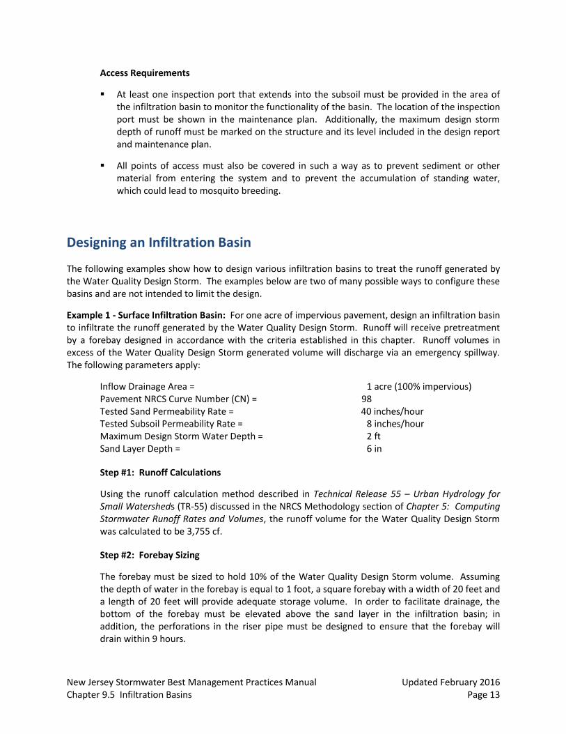
Example 1 - Surface Infiltration Basin: For one acre of impervious pavement, design an infiltration basin to infiltrate the runoff generated by the Water Quality Design Storm. Runoff will receive pretreatment by a forebay designed in accordance with the criteria established in this chapter. Runoff volumes in excess of the Water Quality Design Storm generated volume will discharge via an emergency spillway. The following parameters apply:
Inflow Drainage Area = 1 acre (100% impervious) Pavement NRCS Curve Number (CN) = 98 Tested Sand Permeability Rate = 40 inches/hour Tested Subsoil Permeability Rate = 8 inches/hour Maximum Design Storm Water Depth = 2 ft Sand Layer Depth = 6 in
Step #1: Runoff Calculations
Using the runoff calculation method described in Technical Release 55 – Urban Hydrology for Small Watersheds (TR-55) discussed in the NRCS Methodology section of Chapter 5: Computing Stormwater Runoff Rates and Volumes, the runoff volume for the Water Quality Design Storm was calculated to be 3,755 cf.
Step #2: Forebay Sizing
The forebay must be sized to hold 10% of the Water Quality Design Storm volume. Assuming the depth of water in the forebay is equal to 1 foot, a square forebay with a width of 20 feet and a length of 20 feet will provide adequate storage volume. In order to facilitate drainage, the bottom of the forebay must be elevated above the sand layer in the infiltration basin; in addition, the perforations in the riser pipe must be designed to ensure that the forebay will drain within 9 hours.
New Jersey Stormwater Best Management Practices Manual Updated February 2016 Chapter 9.5 Infiltration Basins Page 14
Step #3: Infiltration Basin Sizing
When designing an infiltration basin, the permeability rate of the subsoil is usually the limiting factor in the design of the system, as is demonstrated in the following analysis. The tested permeability rate of the sand layer is reduced by a safety factor of 2; however, the resulting 20 inches/hour design permeability rate cannot be used in calculations because the maximum design permeability rate allowed is 10 inches/hour. As stated, the subsoil has a tested permeability rate of 8 inches/hour, which is reduced by the same safety factor to yield the design permeability rate of 4 inches/hour; therefore, the design permeability rate of the subsoil will be used in sizing calculations for the bottom of the basin, also known as the infiltration area.
The storage volume of the infiltration basin must be equal to the volume of runoff generated by the Water Quality Design Storm with a maximum runoff depth of 2 feet. Therefore, the required infiltration area for the runoff volume is as follows:
𝐼𝑛𝑓𝑖𝑙𝑡𝑟𝑎𝑡𝑖𝑜𝑛 𝐴𝑟𝑒𝑎 = 𝑊𝑄 𝐷𝑒𝑠𝑖𝑔𝑛 𝑆𝑡𝑜𝑟𝑚 𝑉𝑜𝑙𝑢𝑚𝑒
𝑅𝑢𝑛𝑜𝑓𝑓 𝐷𝑒𝑝𝑡ℎ =
3755 𝑐𝑓
2 𝑓𝑡 = 1877.5 sf
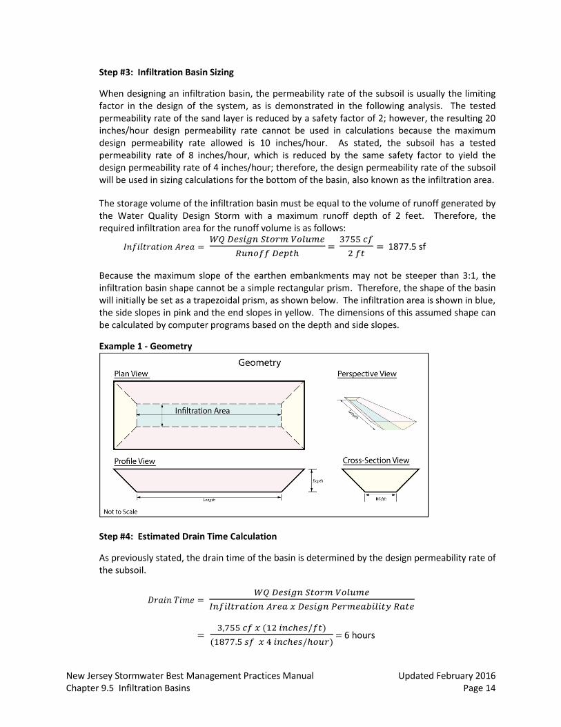
Because the maximum slope of the earthen embankments may not be steeper than 3:1, the infiltration basin shape cannot be a simple rectangular prism. Therefore, the shape of the basin will initially be set as a trapezoidal prism, as shown below. The infiltration area is shown in blue, the side slopes in pink and the end slopes in yellow. The dimensions of this assumed shape can be calculated by computer programs based on the depth and side slopes.
Example 1 - Geometry
Step #4: Estimated Drain Time Calculation
As previously stated, the drain time of the basin is determined by the design permeability rate of the subsoil.
𝐷𝑟𝑎𝑖𝑛 𝑇𝑖𝑚𝑒 = 𝑊𝑄 𝐷𝑒𝑠𝑖𝑔𝑛 𝑆𝑡𝑜𝑟𝑚 𝑉𝑜𝑙𝑢𝑚𝑒
𝐼𝑛𝑓𝑖𝑙𝑡𝑟𝑎𝑡𝑖𝑜𝑛 𝐴𝑟𝑒𝑎 𝑥 𝐷𝑒𝑠𝑖𝑔𝑛 𝑃𝑒𝑟𝑚𝑒𝑎𝑏𝑖𝑙𝑖𝑡𝑦 𝑅𝑎𝑡𝑒
= 3,755 𝑐𝑓 𝑥 (12 𝑖𝑛𝑐ℎ𝑒𝑠/𝑓𝑡)
(1877.5 𝑠𝑓 𝑥 4 𝑖𝑛𝑐ℎ𝑒𝑠/ℎ𝑜𝑢𝑟) = 6 hours
New Jersey Stormwater Best Management Practices Manual Updated February 2016 Chapter 9.5 Infiltration Basins Page 15
Since this is less than the allowable maximum drain time of 72 hours, the infiltration basin has been sized correctly, on an initial basis, to ensure the surface and sand layer are fully drained within the maximum allowable time frame.
Step #5: Check Separation from SHWT
The vertical distance between the lowest elevation of the sand layer and the SHWT must be checked to ensure it meets the minimum requirements. By inspection, the required 2 foot separation from the SHWT is provided.
Step #6: Groundwater Mounding Analysis
Calculate the height of the groundwater mound caused by infiltration to ensure that it will neither prevent infiltration nor damage nearby structures. For information on conducting a groundwater mounding analysis, please see Chapter 6: Groundwater Recharge. For this example, it is assumed the design meets the necessary groundwater mound requirements.
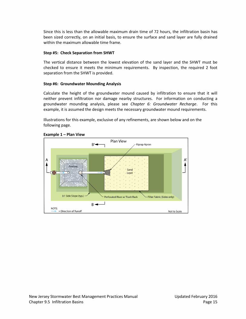
Illustrations for this example, exclusive of any refinements, are shown below and on the following page.
Example 1 – Plan View
New Jersey Stormwater Best Management Practices Manual Updated February 2016 Chapter 9.5 Infiltration Basins Page 16
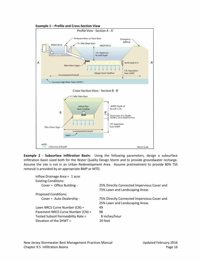
Example 1 – Profile and Cross-Section View
Example 2 - Subsurface Infiltration Basin: Using the following parameters, design a subsurface infiltration basin sized both for the Water Quality Design Storm and to provide groundwater recharge. Assume the site is not in an Urban Redevelopment Area. Assume pretreatment to provide 80% TSS removal is provided by an appropriate BMP or MTD.
Inflow Drainage Area = 1 acre Existing Conditions: Cover = Office Building - 25% Directly Connected Impervious Cover and 75% Lawn and Landscaping Areas Proposed Conditions: Cover = Auto Dealership - 75% Directly Connected Impervious Cover and
25% Lawn and Landscaping Areas Lawn NRCS Curve Number (CN) = 49 Pavement NRCS Curve Number (CN) = 98 Tested Subsoil Permeability Rate = 8 inches/hour Elevation of the SHWT = 20 feet

New Jersey Stormwater Best Management Practices Manual Updated February 2016 Chapter 9.5 Infiltration Basins Page 17
Step #1: Runoff Calculations
Using the runoff calculation method described in Technical Release 55 – Urban Hydrology for Small Watersheds (TR-55) discussed in the NRCS Methodology section of Chapter 5: Computing Stormwater Runoff Rates and Volumes, the runoff volume was calculated to be 939 cf.
Step #2: Design Volume Calculations
The New Jersey Groundwater Recharge Spreadsheet is used to calculate the amount of groundwater recharge required. Land cover is changed from 25% impervious in the existing condition to 75% in the proposed, resulting in a post-development annual recharge deficit of 20,499 cf, as shown in the following image of the Annual Recharge Worksheet:
Example 2 – Post-Development Annual Recharge Deficit Calculation
The design volume for a basin treating the Water Quality Design Storm is 939 cf. Setting the maximum standing water depth to 3 feet, the area required is:
𝐷𝑒𝑠𝑖𝑔𝑛 𝐴𝑟𝑒𝑎 = 𝑀𝑎𝑥𝑖𝑚𝑢𝑚 𝐷𝑒𝑠𝑖𝑔𝑛 𝑆𝑡𝑜𝑟𝑚 𝑉𝑜𝑙𝑢𝑚𝑒
𝑀𝑎𝑥𝑖𝑚𝑢𝑚 𝐷𝑒𝑠𝑖𝑔𝑛 𝑆𝑡𝑜𝑟𝑚 𝐷𝑒𝑝𝑡ℎ=
939 𝑐𝑓
3 𝑓𝑡 = 313 sf
This area must be checked against the area the Groundwater Recharge Spreadsheet indicates is necessary to meet the annual recharge deficit requirement.
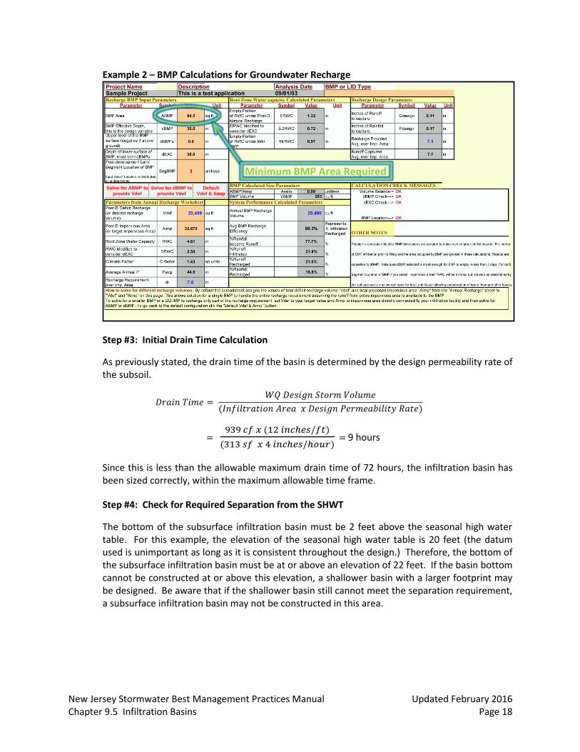
Setting the BMP Effective Depth (dBMP) in the spreadsheet to 36 inches = 3 ft and clicking on the Solve for ABMP button, the resulting area required to meet the recharge requirement is 94.5 sf. Therefore, the chosen dimensions meet the groundwater recharge requirement and are sufficient to provide storage for the Water Quality Design Storm. The following image is of the BMP Calculations Worksheet in the Groundwater Recharge Spreadsheet. The minimum area required for the BMP is circled in green.
New Jersey Stormwater Best Management Practices Manual Updated February 2016 Chapter 9.5 Infiltration Basins Page 18
Example 2 – BMP Calculations for Groundwater Recharge
Step #3: Initial Drain Time Calculation
As previously stated, the drain time of the basin is determined by the design permeability rate of the subsoil.
𝐷𝑟𝑎𝑖𝑛 𝑇𝑖𝑚𝑒 = 𝑊𝑄 𝐷𝑒𝑠𝑖𝑔𝑛 𝑆𝑡𝑜𝑟𝑚 𝑉𝑜𝑙𝑢𝑚𝑒
(𝐼𝑛𝑓𝑖𝑙𝑡𝑟𝑎𝑡𝑖𝑜𝑛 𝐴𝑟𝑒𝑎 𝑥 𝐷𝑒𝑠𝑖𝑔𝑛 𝑃𝑒𝑟𝑚𝑒𝑎𝑏𝑖𝑙𝑖𝑡𝑦 𝑅𝑎𝑡𝑒)
= 939 𝑐𝑓 𝑥 (12 𝑖𝑛𝑐ℎ𝑒𝑠/𝑓𝑡)
(313 𝑠𝑓 𝑥 4 𝑖𝑛𝑐ℎ𝑒𝑠/ℎ𝑜𝑢𝑟) = 9 hours
Since this is less than the allowable maximum drain time of 72 hours, the infiltration basin has been sized correctly, within the maximum allowable time frame.
Step #4: Check for Required Separation from the SHWT
The bottom of the subsurface infiltration basin must be 2 feet above the seasonal high water table. For this example, the elevation of the seasonal high water table is 20 feet (the datum used is unimportant as long as it is consistent throughout the design.) Therefore, the bottom of the subsurface infiltration basin must be at or above an elevation of 22 feet. If the basin bottom cannot be constructed at or above this elevation, a shallower basin with a larger footprint may be designed. Be aware that if the shallower basin still cannot meet the separation requirement, a subsurface infiltration basin may not be constructed in this area.
Solve for ABMP to
provide Vdef
Solve for dBMP to
provide Vdef
Default
Vdef & Aimp
Minimum BMP Area Required
New Jersey Stormwater Best Management Practices Manual Updated February 2016 Chapter 9.5 Infiltration Basins Page 19
Considerations
When planning an infiltration basin, consideration should be given to soil characteristics, depth to the groundwater table, sensitivity of the region, and inflow water quality. It is also important to note that the use of infiltration basins is recommended in this manual only for the Water Quality Design Storm or smaller storm events. Use of these basins to infiltrate larger volumes, should only be considered when another applicable rule or regulation requires the infiltration of a larger storm event. In such a case, the infiltration basin should be designed to infiltrate the minimum storm event required to address that rule or regulation.
In addition to the prohibition of recharge in the areas with high pollutant loading or with runoff exposed to source material as defined in N.J.A.C. 7:8-5.4(a)2iii, the utilization of infiltration basins should consider the impact of infiltration on subsurface sewage disposal systems, water supply wells, groundwater recharge areas protected under the Ground Water Quality Standards rules at N.J.A.C 7:9C, streams under antidegradation protection by the Surface Water Quality Standards rules at N.J.A.C. 7:9B, or similar facilities or areas geologically and ecologically sensitive to pollutants or hydrological changes. Furthermore, the location and minimum distance of the infiltration basin from other facilities or systems shall also comply with all applicable laws and rules adopted by Federal, State, and local government entities.
Pretreatment
As with all other best management practices, pretreatment may extend the functional life and increase the pollutant removal capability of a infiltration basin by reducing incoming velocities and capturing coarser sediments.
Pretreatment may consist of a forebay or any of the structural BMPs found in Chapter 9: Structural Stormwater Management Measures.
There is no adopted TSS removal rate associated with forebays; therefore, their inclusion in any design should be solely for the purpose of facilitating maintenance. Forebays may be earthen, constructed of riprap, or made of concrete and must comply with the following requirements:
□ The forebay must be designed to prevent scour of the receiving basin by outflow from the forebay.
□ The forebay should provide a minimum storage volume of 10% of the Water Quality Design Storm and be sized to hold the sediment volume expected between clean-outs.
□ The forebay should fully drain within nine hours in order to facilitate maintenance and to prevent mosquito issues. Under no circumstances should there be any standing water in the forebay 72 hours after a precipitation event.
□ Surface forebays must meet or exceed the sizing for preformed scour holes in the Standard for Conduit Outlet Protection in the Standards for Soil Erosion and Sediment Control in New Jersey for a surface forebay.
If a concrete forebay is utilized, it must have at least two weep holes to facilitate low level drainage.

New Jersey Stormwater Best Management Practices Manual Updated February 2016 Chapter 9.5 Infiltration Basins Page 20
When using a structural BMP for pretreatment, it must be designed in accordance with the design requirements outlined in its respective chapter. For additional information on the design requirements of each structural BMP, refer to the appropriate chapter in this manual.
Soil Characteristics
Soils are perhaps the most important consideration for site suitability. In general, County Soil Surveys may be used to obtain necessary soil data for planning and preliminary design of infiltration basins. However, as previously mentioned, for final design and construction, soil tests are required at the exact location of the proposed basin in order to confirm its ability to function properly without failure. In order to confirm reasonable data consistency, the results of soil testing should be compared with the County Soil Survey data that was used in the computation of runoff rates and volumes and the design of on-site BMPs. If significant differences exist between the soil test results and the County Soil Survey data, additional soil tests are recommended to determine and evaluate the extent of the data inconsistency and whether there is a need for revised site runoff and BMP design computations. All significant inconsistencies should be discussed with the local Soil Conservation District prior to proceeding with such a redesign to help ensure that the final site soil data is accurate.
Geology
The presence or absence of Karst topography is an important consideration when designing an infiltration basin; in areas of the State with this type of geology, the bedrock is composed of highly soluble rock. If Karst topography is present, infiltration of runoff may lead to subsidence and sinkholes; therefore, careful consideration must be taken in these areas. For more information on design and remediation in areas of Karst topography, refer to the Standards for Soil Erosion and Sediment Control in New Jersey: Investigation, Design and Remedial Measures for Areas Underlain by Cavernous Limestone.
Maintenance
Regular and effective maintenance is crucial to ensure effective infiltration basin performance; in addition, maintenance plans are required for all stormwater management facilities on a major development. There are a number of required elements in all maintenance plans, pursuant to N.J.A.C. 7:8-5.8; these are discussed in more detail in Chapter 8: Maintenance of Stormwater Management Measures. Furthermore, maintenance activities are required through various regulations, including the New Jersey Pollutant Discharge Elimination System (NJPDES) rules, N.J.A.C. 7:14A. Specific maintenance requirements for infiltration basins are presented below; these requirements must be included in the basin’s maintenance plan.
General Maintenance
Proper and timely maintenance is essential to continuous, effective operation; therefore, an access route must be incorporated into the design, and it must be properly maintained.
All structural components must be inspected, at least once annually, for cracking, subsidence, spalling, erosion and deterioration.
New Jersey Stormwater Best Management Practices Manual Updated February 2016 Chapter 9.5 Infiltration Basins Page 21
Components expected to receive and/or trap debris and sediment must be inspected for clogging at least four times annually, as well as after every storm exceeding 1 inch of rainfall.
Sediment removal should take place when all runoff has drained from the planting bed and the basin is dry.
Disposal of debris, trash, sediment and other waste material must be done at suitable disposal/recycling sites and in compliance with all applicable local, state and federal waste regulations.
Access points for maintenance are required on all enclosed areas within an infiltration basin; these access points must be clearly identified in the maintenance plan. In addition, any special training required for maintenance personnel to perform specific tasks, such as confined space entry, must be included in the plan.
Stormwater BMPs may not be used for stockpiling of plowed snow and ice, compost, or any other material.
Drain Time
The basin must be inspected at least twice annually to determine if the permeability of the basin has decreased.
The design drain time for the maximum design storm runoff volume must be indicated in the maintenance manual.
If the actual drain time is longer than the design drain time, the components must be evaluated and appropriate measures taken to return the infiltration basin to the original tested as-built condition.
If the infiltration basin fails to drain the Water Quality Design Storm within 72 hours, corrective action must be taken and the maintenance manual revised accordingly to prevent similar failures in the future. Note that annual tilling of the sand layer, using lightweight equipment, may assist in maintaining the infiltration capacity of a surface type system by breaking up clogged surfaces.
New Jersey Stormwater Best Management Practices Manual Updated February 2016 Chapter 9.5 Infiltration Basins Page 22
References
Horner, R.R., J.J. Skupien, E.H. Livingston and H.E. Shaver. August 1994. Fundamentals of Urban Runoff Management: Technical and Institutional Issues. In cooperation with U.S. Environmental Protection Agency. Terrene Institute. Washington, D.C.
Livingston E.H., H.E. Shaver, J.J. Skupien and R.R. Horner. August 1997. Operation, Maintenance, & Management of Stormwater Management Systems. In cooperation with U.S. Environmental Protection Agency. Watershed Management Institute. Crawfordville, FL.
New Jersey Department of Agriculture. January 2014. Standards for Soil Erosion and Sediment Control in New Jersey. State Soil Conservation Committee. Trenton, NJ.
New Jersey Department of Environmental Protection and Department of Agriculture. December 1994. Stormwater and Nonpoint Source Pollution Control Best Management Practices. Trenton, NJ.
New Jersey Pinelands Commission. September 2014. Pinelands Comprehensive Management Plan. New Lisbon, NJ.
Ocean County Planning and Engineering Departments and Killam Associates. June 1989. Stormwater Management Facilities Maintenance Manual. New Jersey Department of Environmental Protection. Trenton, NJ.
Schueler, T.R. July 1987. Controlling Urban Runoff: A Practical Manual for Planning and Designing Urban BMPs. Metropolitan Washington Council of Governments. Washington, D.C.
Schueler, T.R., P.A. Kumble and M. Heraty. March 1992. A Current Assessment of Urban Best Management Practices. Metropolitan Washington Council of Governments. Washington, D.C.
Schueler, T.R. and R.A. Claytor. 2000. Maryland Stormwater Design Manual. Maryland Department of the Environment. Baltimore, MD.