9-43. tracking and dynamic balancing - tail rotor assembly...
TRANSCRIPT
9-43. Tracking and Dynamic Balancing - Tail Rotor Assembly
NOTE
It is not necessary to track the tail rotor blades on Enstrom tail rotor assemblies. Earlier tail rotor assemblies (F & C series helicopters) with the 3 piece pitch links should be set to an overall outside length of 4.26“ (10.82 cm) in accordance with paragraph 12-125 of the maintenance manual.
NOTE
The use of the Honeywell-Chadwick 2000 system is described in the following instructions. Follow the operating instructions for the equipment being used if different than the following instructions.
NOTE
The procedures outlined below should work for any of the digital balance systems but because most of them install the velocimeter in the vertical orientation the polar chart will have to be rotated to compensate.
A. Install the tracking and balancing equipment as follows:
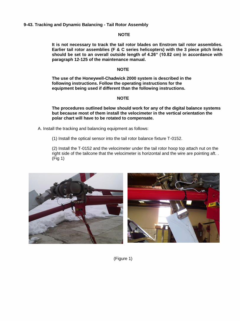
(1) Install the optical sensor into the tail rotor balance fixture T-0152.
(2) Install the T-0152 and the velocimeter under the tail rotor hoop top attach nut on the right side of the tailcone that the velocimeter is horizontal and the wire are pointing aft. . (Fig 1)
(Figure 1)
-2-
(3) Connect the velocimeter and optical sensor cables and wrap the cables around the stinger tube, around the right side horizontal stabilizer, the right rear oleo/cross tube, and then into the right side cabin door. Secure the cables to the stinger tube, tailcone, and landing gear with tape.
(4) Install a 1.5 " piece of reflective tape on one of the blade grips lengthwise. (This will be the target blade. (Figure 1)
(5) Connect the velocimeter and optical sensor cables to the Balancer box in accordance with the manufactures instructions.
B. Balance the tail rotor using the following procedures:
WARNING
The following steps are to be performed by authorized personnel.
(1) Position the helicopter so the tail rotor gearbox output shaft is pointing into the wind. It does not make any difference if the tail rotor assembly is up wind or downwind from the tail rotor gearbox.
(2) (480, and TH series helicopters) Ground run the helicopter at 101% ± 1% N
2
with the tail rotor pedals neutral.
(3) (F and C series helicopters) Ground run the helicopter at 3050 engine RPM (350 Rotor RPM) with the tail rotor pedals neutral.
(4) Using the procedures outlined in the balancer operation instructions; obtain a clock angle and ips reading.
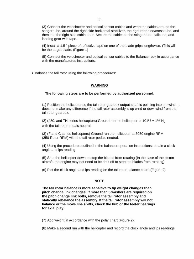
(5) Shut the helicopter down to stop the blades from rotating (In the case of the piston aircraft, the engine may not need to be shut off to stop the blades from rotating). (6) Plot the clock angle and ips reading on the tail rotor balance chart. (Figure 2)
NOTE
The tail rotor balance is more sensitive to tip weight changes than pitch change link changes. If more than 5 washers are required on the pitch change link bolts, remove the tail rotor assembly and statically rebalance the assembly. If the tail rotor assembly will not balance or the move line shifts, check the hub or the teeter bearings for axial play.
(7) Add weight in accordance with the polar chart (Figure 2).
(8) Make a second run with the helicopter and record the clock angle and ips readings.
. -3-
(Figure 2)
-4-
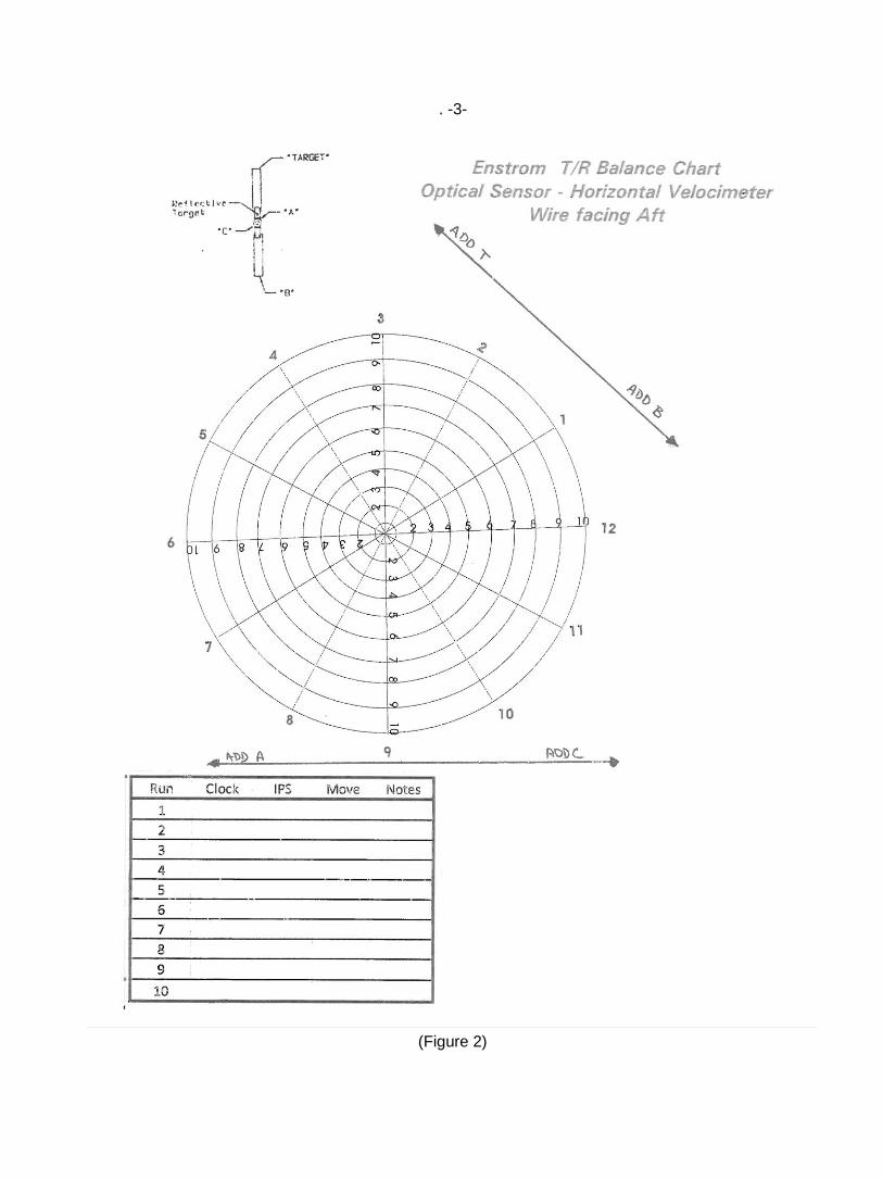
NOTE
If more than 5 washers are required on the pitch change link bolts, the teeter hub can be shifted to move the balance fulcrum (See section D of this procedure). On early production tail rotors, with the KP8A or KRP8A( ) bearings the tail rotor must be removed to shift the teeter hub. On current production tail rotors, the teeter trunnion can be shifted by without removing the tail rotor from the helicopter. (See section D)
CAUTION
If adding or subtracting washers from the pitch change link bolts, ensure the correct grip length bolt is installed and account for the weight change of the bolt during the balancing procedure.
NOTE
If the TR is difficult to balance plot the move lines for both the tip weights and the pitch link weights. If the two move lines are parallel or don’t intersect, then remove the tail rotor from the gearbox, turn it 180° and re-install it. It will also be necessary to rotate the trunnion 180° to maintain the 8° lag of rotation. (Figure 9-38, page MM-9-125) (7) Proceed to balance the tail rotor until the "IPS" reading is .2 ips or less.
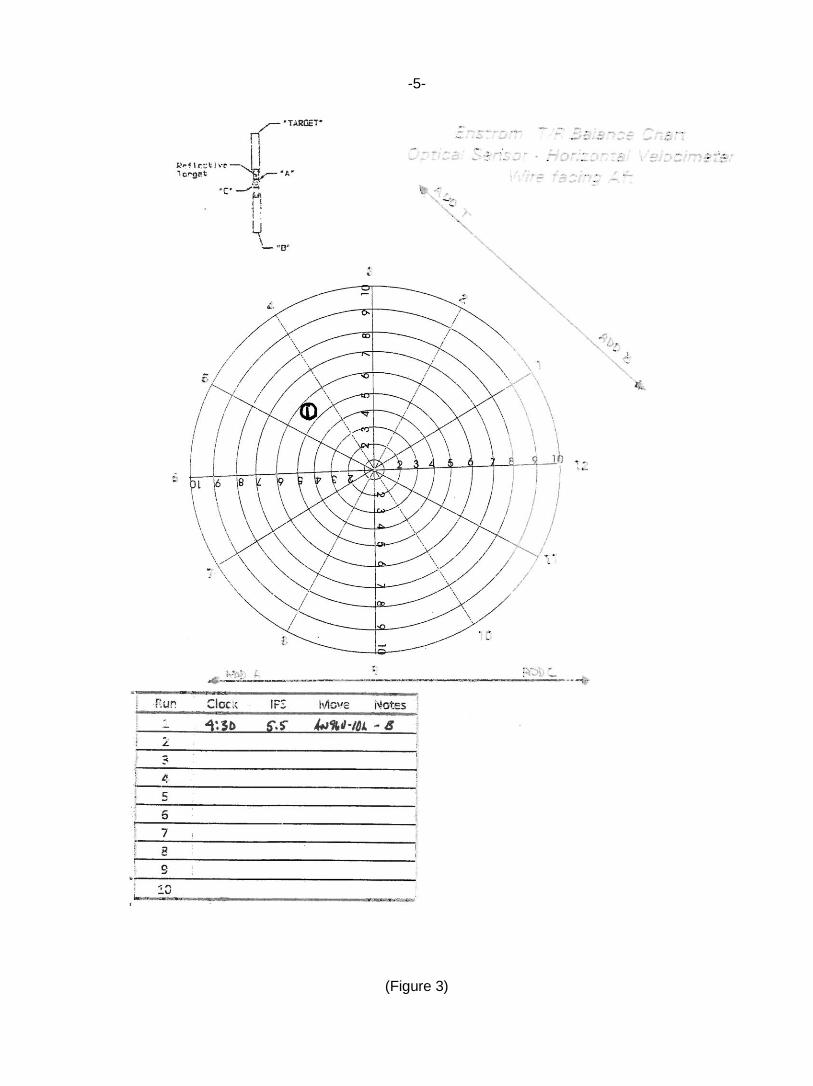
C. Procedure to adjust clock angle. (1) Using the procedures outlined in section (B) above, obtain a clock angle and IPS reading.
(2) As an example, the following readings are recorded for run 1; .55 ips @ 4:30 clock angle.
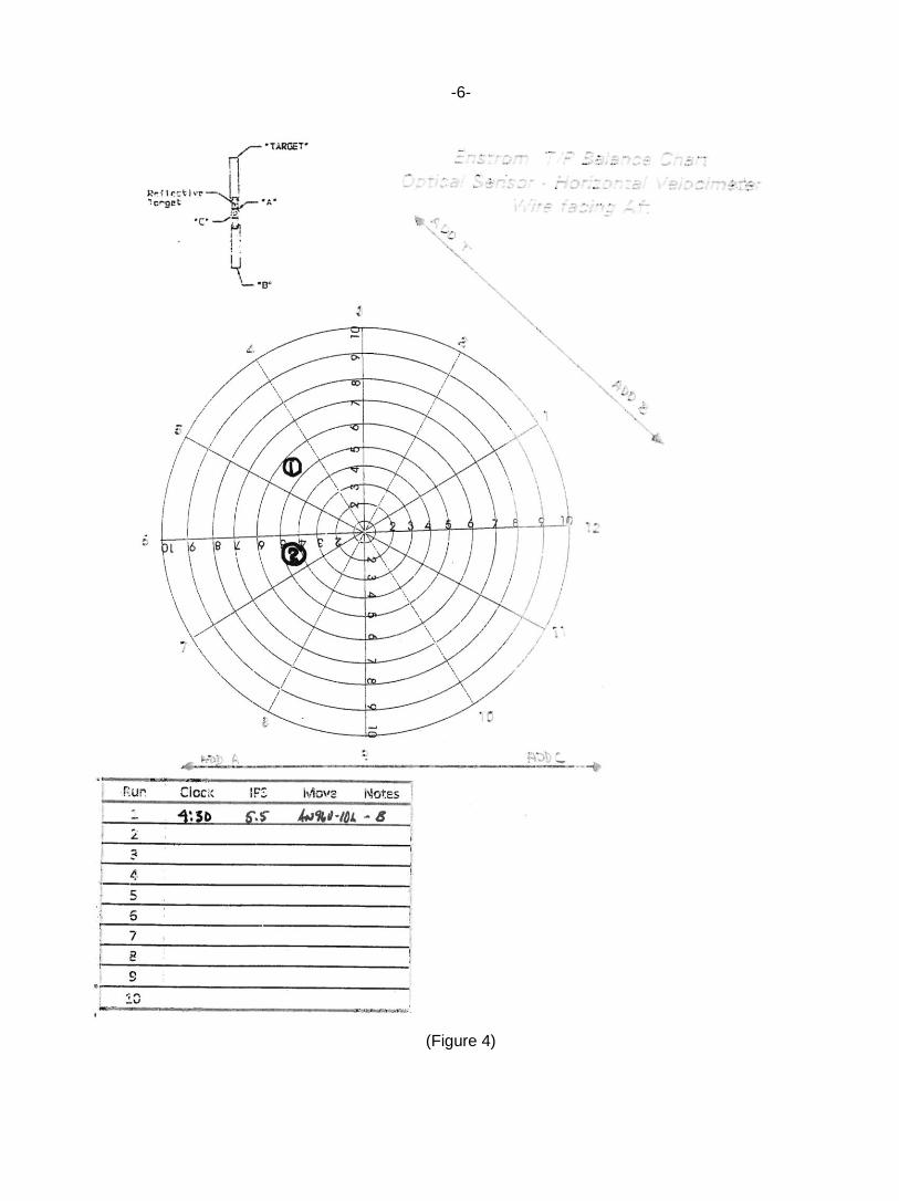
(3) Plot Run 1 on the TR polar chart. (Fig 3) (4) Add an AN960-10L washer to the tip at position B. (5) Run the helicopter again and record the run 2. In this case we get: 4.5 ips @ 6:30 clock angle. (6) Plot run two on the polar chart. (Figure 4)
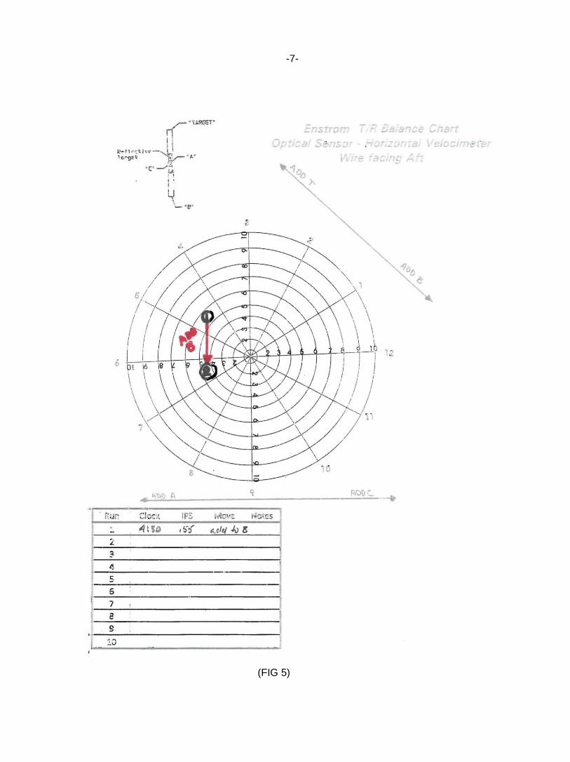
(7) It can be seen that the second run did not result in the target moving in the expected direction. It will be necessary to correct the chart to agree with what is actually happening with the helicopter. (8) Drawn a line between plot 1 and plot 2 and label it “add B” (Figure 5)
-5-
(Figure 3)
-6-
(Figure 4)
-7-
(FIG 5)
-8-
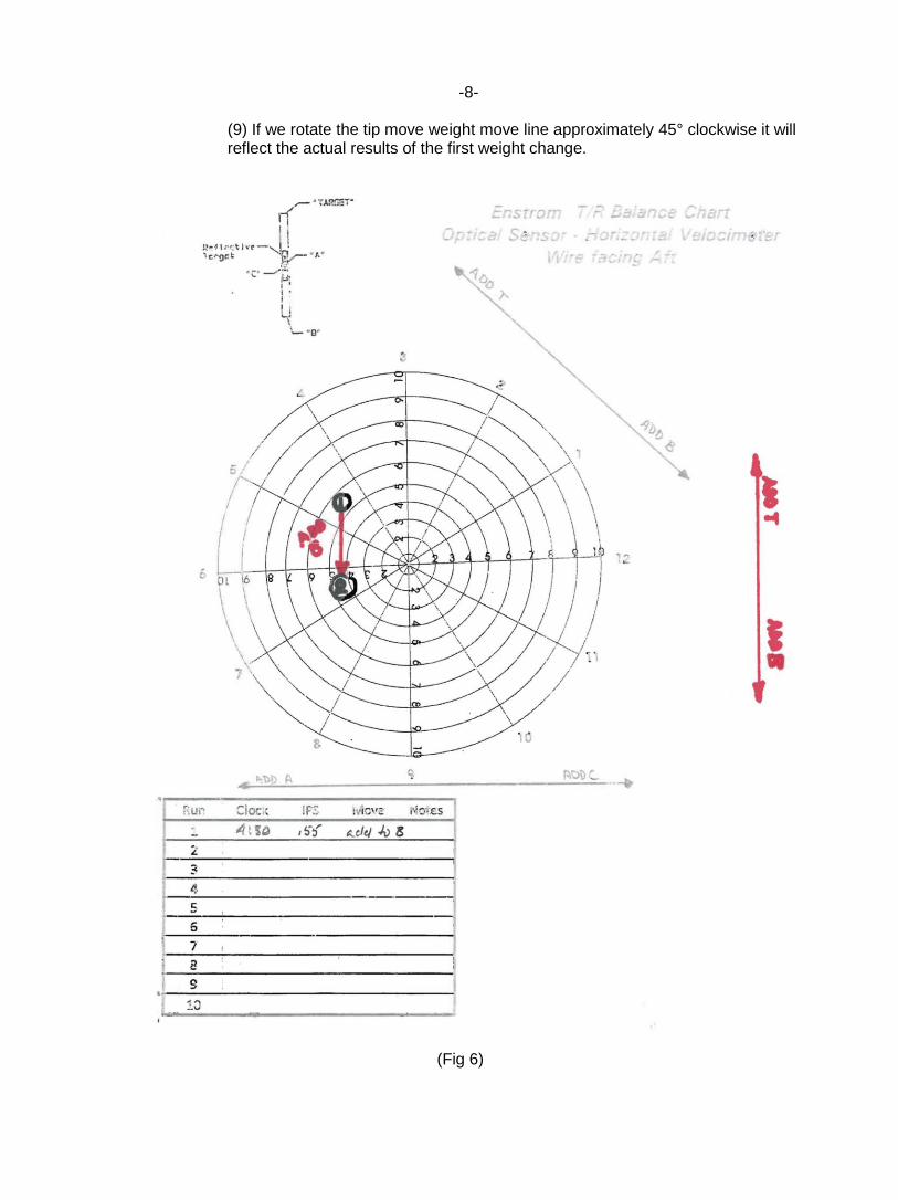
(9) If we rotate the tip move weight move line approximately 45° clockwise it will reflect the actual results of the first weight change.
(Fig 6)
-9-
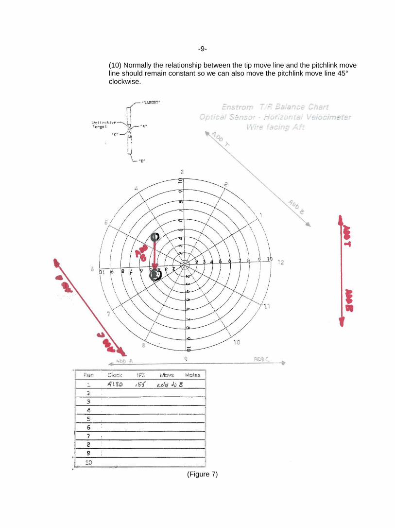
(10) Normally the relationship between the tip move line and the pitchlink move line should remain constant so we can also move the pitchlink move line 45° clockwise.
(Figure 7)
-10-
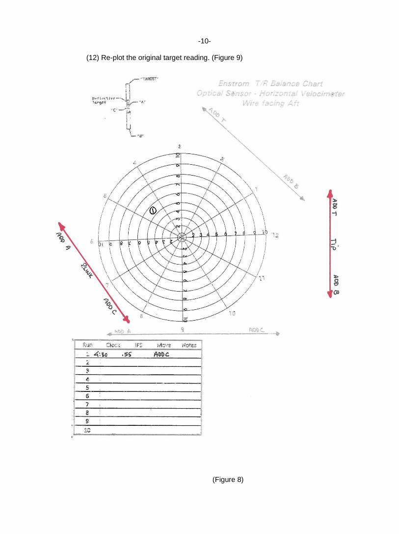
(12) Re-plot the original target reading. (Figure 9)
(Figure 8)
-11-
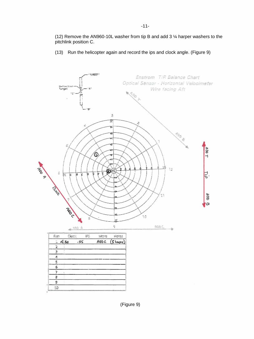
(12) Remove the AN960-10L washer from tip B and add 3 ¼ harper washers to the pitchlink position C. (13) Run the helicopter again and record the ips and clock angle. (Figure 9)
(Figure 9)
-12-
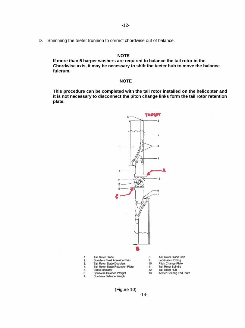
D. Shimming the teeter trunnion to correct chordwise out of balance. NOTE
If more than 5 harper washers are required to balance the tail rotor in the Chordwise axis, it may be necessary to shift the teeter hub to move the balance fulcrum.
NOTE
This procedure can be completed with the tail rotor installed on the helicopter and it is not necessary to disconnect the pitch change links form the tail rotor retention plate.
(Figure 10) -14-
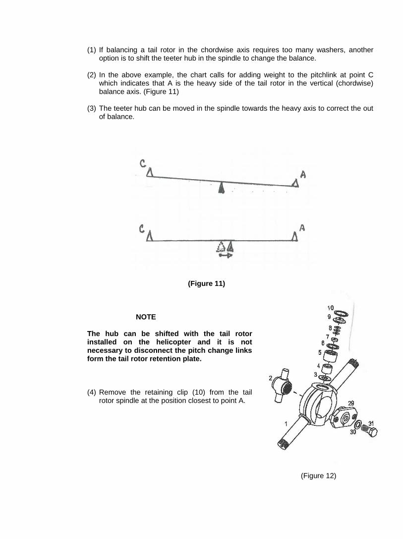
(1) If balancing a tail rotor in the chordwise axis requires too many washers, another
option is to shift the teeter hub in the spindle to change the balance.
(2) In the above example, the chart calls for adding weight to the pitchlink at point C which indicates that A is the heavy side of the tail rotor in the vertical (chordwise) balance axis. (Figure 11)
(3) The teeter hub can be moved in the spindle towards the heavy axis to correct the out of balance.
(Figure 11)
NOTE
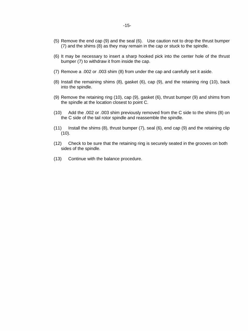
The hub can be shifted with the tail rotor installed on the helicopter and it is not necessary to disconnect the pitch change links form the tail rotor retention plate. (4) Remove the retaining clip (10) from the tail
rotor spindle at the position closest to point A.
(Figure 12)
-15-
(5) Remove the end cap (9) and the seal (6). Use caution not to drop the thrust bumper (7) and the shims (8) as they may remain in the cap or stuck to the spindle.
(6) It may be necessary to insert a sharp hooked pick into the center hole of the thrust bumper (7) to withdraw it from inside the cap.
(7) Remove a .002 or .003 shim (8) from under the cap and carefully set it aside.
(8) Install the remaining shims (8), gasket (6), cap (9), and the retaining ring (10), back into the spindle.
(9) Remove the retaining ring (10), cap (9), gasket (6), thrust bumper (9) and shims from the spindle at the location closest to point C.
(10) Add the .002 or .003 shim previously removed from the C side to the shims (8) on the C side of the tail rotor spindle and reassemble the spindle.
(11) Install the shims (8), thrust bumper (7), seal (6), end cap (9) and the retaining clip (10).
(12) Check to be sure that the retaining ring is securely seated in the grooves on both sides of the spindle.
(13) Continue with the balance procedure.