879482-j ecn6228 d wilson - climate wizard€¦ · pressure range required ... psychrometric chart,...
TRANSCRIPT

(English) (CW-H10, CW-H15)
CW-H Indirect Evaporative Cooler
APPLICATION GUIDE

i Indirect Evaporative Air Conditioner
CONTENTS
GENERAL 1SERVICES - Water, Electricity & Drain 2APPLICATIONS 3
Stand alone cooling 4Supplementary cooling 5Cold front cooling 6
DIMENSIONS 9ELECTRICAL WIRING DIAGRAM 10PSYCHROMETRIC CHART 12CONTROL SCHEMES 13
Local zone control 13Control from remote location 13Error signal 13Remote On-Off 14Water Management system 14LED indicator - Fault code diagnosis 17

GENERALClimate Wizard is an “Indirect Evaporative Air Cooler” that is capable of delivering cooled air, at temperaturesthat are very similar to those produced by refrigerated air conditioners. The Climate Wizard comprises of one (1) backward curved,high pressure, single inlet, centrifugal fan directly connected to an electronically commutated motor (ECM), a multi-patented heatexchanger core, a water reservoir and water distribution system including circulating centrifugal pump(s), automatic chlorinationdevice and an auto water management feature.
Climate Wizard remove moisture, but it add any moisture.
Climate Wizard is manufactured in two configurations - HORIZONTAL and VERTICAL. This Application Guide refers to theHORIZONTAL configuration only.The heat exchanger core may comprise of 2 or 3 sections.
The 2-section model is the CW-H10, with nominal cooling capacity of 10 kW*The 3-section model is the CW-H15, with nominal cooling capacity of 15 kW*.* [Cooling capacity is calculated at inlet conditions of 38°C dry-bulb, 10°C dew point and 27.4°C room temperatures, generally inaccordance with Australian Standard AS2913-2000. This capacity applies only when the Climate Wizard is being used in StandAlone Cooling applications. For Cold Front Cooling higher capacities apply.
Not all the inlet air is delivered into the building. Inside the Climate Wizard the air is divided into two streams. One stream is super-cooled (the ‘supply air’) and delivered into the building, and the second stream (the ‘reject air’) is used to intensify the wet-bulbdepression; it is supersaturated and discharged to atmosphere along with all the heat that has been removed from the dry fresh airstream.
External Static pressure affects the behaviour of the two air streams inside the machine. A means of compensating for the external
static pressure is provided on the Climate Wizard - see later information in this Guide.
The Climate Wizard is intended to be installed external to any building, but may also be installed indoors, for example in an air
conditioning plant room provided that fresh outside air can be supplied to the cooler and that the exhaust air is discharged to the
exterior of the building.
with no added moisture
cannot does not
APPLICATION GUIDEIndirect Evaporative Air Conditioner
INLET(AMBIENT)
AIR
EXHAUSTAIR (WARM
& MOIST)
SUPPLYAIR (COOL
& DRY)
SEELEY INTERNATIONAL – APPLICATION GUIDE 1
GENERAL ….cont’d
SERVICES - water, electricity & drain
USA Installations
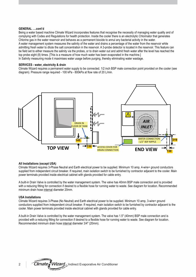
Being a water based machine Climate Wizard incorporates features that recognise the necessity of managing water quality and ofcomplying with Codes and Regulations for health protection. Inside the cooler there is an electrolytic Chlorinator that generatesChlorine gas in the water reservoir and behaves as a permanent biocide to annul any bacterial activity in the water.A water management system measures the salinity of the water and drains a percentage of the water from the reservoir whileadmitting fresh water to dilute the salt concentration in the reservoir. A 3-probe detector is located in the reservoir. This feature canbe field set to either measure the salinity via the probes, or to drain water out and admit fresh water after the level has reached thetop probe eight (8) times. [This is a measure of how much water has been evaporated in the machine.]In Salinity measuring mode it maximises water usage before purging, thereby eliminating water wastage.
Climate Wizard requires a permanent water supply to be connected. 1/2 inch BSP male connection point provided on the cooler (seediagram). Pressure range required - 100 kPa - 800kPa at flow rate of 20 L/min.
Climate Wizard requires 3-Phase Neutral and Earth electrical power to be supplied. Minimum 10 amp, 4-wire+ ground conductorssupplied from independent circuit breaker. If required, main isolation switch to be furnished by contractor adjacent to the cooler. Mainpower terminals provided inside electrical cabinet with glands provided for cable entry.
A built-in Drain Valve is controlled by the water management system. The valve has 40mm BSP male connection and is providedwith a reducing fitting for connection if desired to a flexible hose for running water to waste. See diagram for location. Recommendedminimum drain hose diameter 20mm.
All Installations (except USA)
internal
Climate Wizard requires 3-Phase (No Neutral) and Earth electrical power to be supplied. Minimum 10 amp, 3-wire+ groundconductors supplied from independent circuit breaker. If required, main isolation switch to be furnished by contractor adjacent to thecooler. Main power terminals provided inside electrical cabinet with glands provided for cable entry.
A built-in Drain Valve is controlled by the water management system. The valve has 1.5" (40mm) BSP male connection and isprovided with a reducing fitting for connection if desired to a flexible hose for running water to waste. See diagram for location.Recommended minimum drain hose diameter 3/4" (20mm).internal
TOP VIEW
145
130
DRAIN IN
FLOOR OF TANK
319
ACCESS COVER FOR
DRAIN CONNECTION
WATER CONNECTION
- 1/2” BSP NIPPLE
130
AIR
INLET
END VIEW
2 Indirect Evaporative Air Conditioner

Climate Wizard is designed to be used in 3 different types of applications:STAND ALONE COOLING - in cases where the Climate Wizard is the primary source of Air Conditioning for the building.
SUPPLEMENTARY COOLING - in cases where the Climate Wizard is used to augment the capacity of the existing airconditioning system, or to extend its reach into the building, or to greatly reduce the energy consumption of the AirConditioning plant.
COLD FRONT COOLING - in cases where the Climate Wizard is used to pre-cool the fresh air supply to new or existingrefrigerated air conditioning plants in order to prolong the life of the plants, to save significant energy, and to greatly reducedemand on existing infrastructure which becomes over-stressed in heat-wave conditions.
In each application type, remarkable energy savings can be achieved compared with conventional Refrigerated Air Conditioning.THE HOTTER THE CLIMATE THE MORE SAVINGS WILL BE MADE.
See following pages for details of each application type.
!
!
!
CW
STAND ALONE COOLING
CW
COLD FRONT COOLING
AC AC
CW
SUPPLEMENTARY COOLING
AC
CW
CW
SEELEY INTERNATIONAL – APPLICATION GUIDE 3

STAND ALONE COOLING:
Sizing:
Climate Wizard can be used to supply the entire air conditioning demand of a building.
The Climate Wizard is intended to be installed external to any building, but may also be installed indoors, for example in an airconditioning plant room provided that fresh outside air can be supplied to the cooler and that the exhaust air is discharged directly tothe exterior of the building.
The supply air temperature delivered by the Climate Wizard, and its airflow, is similar to the temperature and airflow of a refrigeratedAir Conditioner. Therefore the air distribution design should follow similar parameters of design and installation. Essentially thatmeans similar duct sizes, similar outlet design and attention given to the avoidance of cold air drafts. The use of Zones is acceptableprovided that used air can exit the building satisfactorily.
IT IS ESSENTIAL THAT THE PLANT BE SO ARRANGED THAT THE CLIMATE WIZARD EXHAUST AIR CANNOT BE RE-CIRCULATED INTO THE AIR INLET OF THE COOLER.
It should be understood that the Climate Wizard performance is similar to a refrigerated Air Conditioner in regard to the supply airtemperature and the ‘no added moisture’ feature. Since refrigerated Air Conditioners are sized on the basis of a heatload calculation,Climate Wizard must be treated in the same way. Contractors should therefore continue to use their regular method for determiningthe heatload of a building and apply the Climate Wizard to the ‘sensible’ component of that heatload. The ‘Air Change Rate’ methodthat is often used for Direct Evaporative Air Coolers is NOT to be used.However, the rated capacity of the Climate Wizard will vary according to the local climate conditions, and the indoor temperaturesetting. Thus a second calculation must be made before the final sizing of the cooler can be made.
For the CW-H10: Cooling capacity = K1 x T watts [K1 = specific heat x density x airflow = 1.23 x 800 L/sec = 984)rT = (Tset room - Tsupply)] [Tsupply is found in Psychrometric Chart, Page 10.]
For the CW-H15: Cooling capacity = K2 x T watts [K2 = specific heat x density x airflow = 1.23 x 1100 L/sec = 1353)rT = (Tset room - Tsupply)] [Tsupply is found in ]
r
rPsychrometric Chart, Page 10.
4 Indirect Evaporative Air Conditioner

SUPPLEMENTARY COOLING:
Sizing:
Climate Wizard can be used to boost or supplement the existing air conditioning capacity of a building. In this application the ClimateWizard will be installed in a similar way to the Stand Alone application, but will be sized to provide added cooling capacity to thebuilding. It can also be used to supply all the fresh air requirement of a building and in this case it will be sized according to the freshair quantity requirement.The Climate Wizard is intended to be installed external to any building, but may also be installed indoors, for example in an airconditioning plant room provided that fresh outside air can be supplied to the cooler and that the exhaust air is discharged directly tothe exterior of the building.The supply air temperature delivered by the Climate Wizard, and its airflow, is similar to the temperature and airflow of a refrigeratedAir Conditioner. Therefore the air distribution design should follow similar parameters of design and installation. Essentially thatmeans similar duct sizes, similar outlet design and attention given to the avoidance of cold air drafts. The use of Zones is acceptableprovided that used air can exit the building satisfactorily.
IT IS ESSENTIAL THAT THE PLANT BE SO ARRANGED THAT THE CLIMATE WIZARD EXHAUST AIR CANNOT BERECIRCULATED INTO THE AIR INLET OF THE COOLER.
The decision to install supplementary cooling equipment will arise from a number of causes:Existing plant is overloadedExisting plant is nearing end of lifeEnergy consumption of building must be reduced but ‘Cold Front Cooling’ (see later heading) option is either not possible or not
economicalBuilding has been extended but existing plant is at full capacity
In addressing points 1,2,3 above, since the Climate Wizard delivers 100% fresh air and with no added moisture, the fresh air intakeof the existing Air Conditioning plant should be closed in order for the Climate Wizard to provide all the fresh air required for thebuilding. This will have the immediate effect of reducing the load on the existing plant and saving energy. The decision about thequantity of Climate Wizard coolers depends entirely on matching the Climate Wizard airflow with the quantity of fresh air that wasbeing delivered by the existing plant. The amount of energy that was being consumed by the existing plant will be greatly decreasedbecause the Climate Wizard can cool the same quantity of fresh air for much less consumed energy. See table under
. The maximum supply airflow of the 2 Climate Wizard models is:
CW-H10 approx. 800 L/sec at 200 PaCW-H15 approx. 1100 L/sec at 200 Pa
!
!
!
!
Cold FrontCooling
Addressing point 4 above, the foregoing procedure may be adequate to cope with the increased load, but if not, additional ClimateWizard coolers may be installed. In this case the cooling capacity of the Climate Wizard should be calculated in the same way as forStand Alone cooling, using local climate data and the desired indoor room temperature required by the Owners.
For the CW-H10: Cooling capacity = K1 x rT watts [K1 = specific heat x density x airflow = 1.23 x 800 L/sec = 984)rT = (Tset room - Tsupply)] [Tsupply is found in Psychrometric Chart, Page 10.]
For the CW-H15: Cooling capacity = K2 x rT watts [K2 = specific heat x density x airflow = 1.23 x 1100 L/sec = 1353)rT = (Tset room - Tsupply)] [Tsupply is found in Psychrometric Chart, Page 10.]
SEELEY INTERNATIONAL – APPLICATION GUIDE 5

COLD FRONT COOLING:Cold Front Cooling describes the case in which Climate Wizard is used to pre-cool the fresh air component of a refrigerated airconditioning plant. In most countries and jurisdictions around the world a mandatory quantity of fresh air is required to be delivered into thebuilding as a percentage of the total air quantity of the air conditioning system. This quantity is often up to 25% of the total air requirementof the plant. Climate Wizard will completely cool this air at very low cost.
It is therefore extremely cost effective to use Climate Wizard to perform this function and thereby reduce the load on the refrigeration plant,and its wear and tear while greatly reducing the cost of running the plant.
The Climate Wizard is intended to be installed external to any building, but may also be installed indoors, for example in an air conditioningplant room provided that fresh outside air can be supplied to the cooler and that the exhaust air is discharged directly to the exterior of thebuilding.
IT IS ESSENTIALTHAT THE PLANT BE SOARRANGED THAT THE CLIMATE WIZARD EXHAUSTAIR CANNOT BE RECIRCULATEDINTO THEAIR INLET OF THE COOLER.
Advice to Designers:1. Avoid coil entering air temperatures falling below 21°C as this may prevent 100% evaporation of the liquid in the
evaporator coil, leading to serious compressor damage. There is no provision in the Climate Wizard to protectagainst this occurrence.
2. Avoid the temperature of air mixtures exceeding 31°C entering the evaporator coil as this may cause compressorfailure on the high pressure cut-out. There is no provision in the Climate Wizard to protect against this occurrence.
3. Under certain conditions of low moisture content, pre-cooled air from the Climate Wizard may be delivered into theAHU downstream of the evaporator coil.
Examples of typical designs:
1. Climate Wizard installed on roof and ducted into Air Conditioning plant room below
Alternative sitefor CW
Fresh airintake
Return air
A-C UNIT
Fresh air louvres to beclosed when Climate Wizard
installed on roof
Supply air tobuilding
CW
CW
6 Indirect Evaporative Air Conditioner

COLD FRONT COOLING (cont’d):
Examples of typical designs (cont’d):
! Climate Wizard installed on roof and ducted directly into fresh air intake ofAir Conditioner in plant room below.
Two examples of Climate Wizard Cold Front Cooling installations inAustralia
aa
aa
aa
aa
aa
aa
aa
aa
aa
aa
aa
aa
aa
aa
aa
aa
aa
aa
aa
aa
aa
aa
aa
aa
aa
aa
aa
aa
aa
aa
aaaaaaaaaaaaaaaaaaaaaaaaaaaaaaaaaaaaaaaaaaaaaaaaaa
Alternative sitefor CW
Fresh airintake
Barometricdamper
Return air
A-C UNIT
Supply air tobuilding
CW
CW
SEELEY INTERNATIONAL – APPLICATION GUIDE 7

COLD FRONT COOLING (cont’d):
The Barometric Damper may be controlled by natural pressure variations or, if motorised, by the control system, depending onwhether the Climate Wizard is required to function or not.
Cold Front Cooling means pre-cooling warm (hot) fresh air that is required by a refrigerated Air-Conditioning plant. SinceClimate Wizard cools fresh air down to almost the dewpoint and does not add any moisture, it is the ideal product to pre-cool thefresh air. This low-cost pre-cooled air creates immediate energy savings for the building and it reduces the load on the refrigerationequipment, thereby extending the life of the plant and saving capital outlay. It also enables load to be removed from the existingover-stressed electrical power infrastructure, and especially so in heat-wave conditions.
First ascertain the quantity of fresh air of which the refrigerated Air Conditioning plant is capable. Match this quantity to the quantityof air of the Climate Wizard will deliver. The maximum supply airflow of the 2 Climate Wizard models is:
CW-H10 approx. 800 L/sec at 200 PaCW-H15 approx. 1100 L/sec at 200 Pa
For customers who need to know the energy saving, the provides the Cooling Effect in kW of eachmodel at various ambient conditions.
Further reductions in energy consumption can be achieved when a portion of the return air is ducted via the Climate Wizard.
Maximising the use of return air can also open up further very viable possibilities for Climate Wizard in localities with extremely highdewpoint temperatures. These are special cases and lie outside the scope of this Guide.
Sizing:
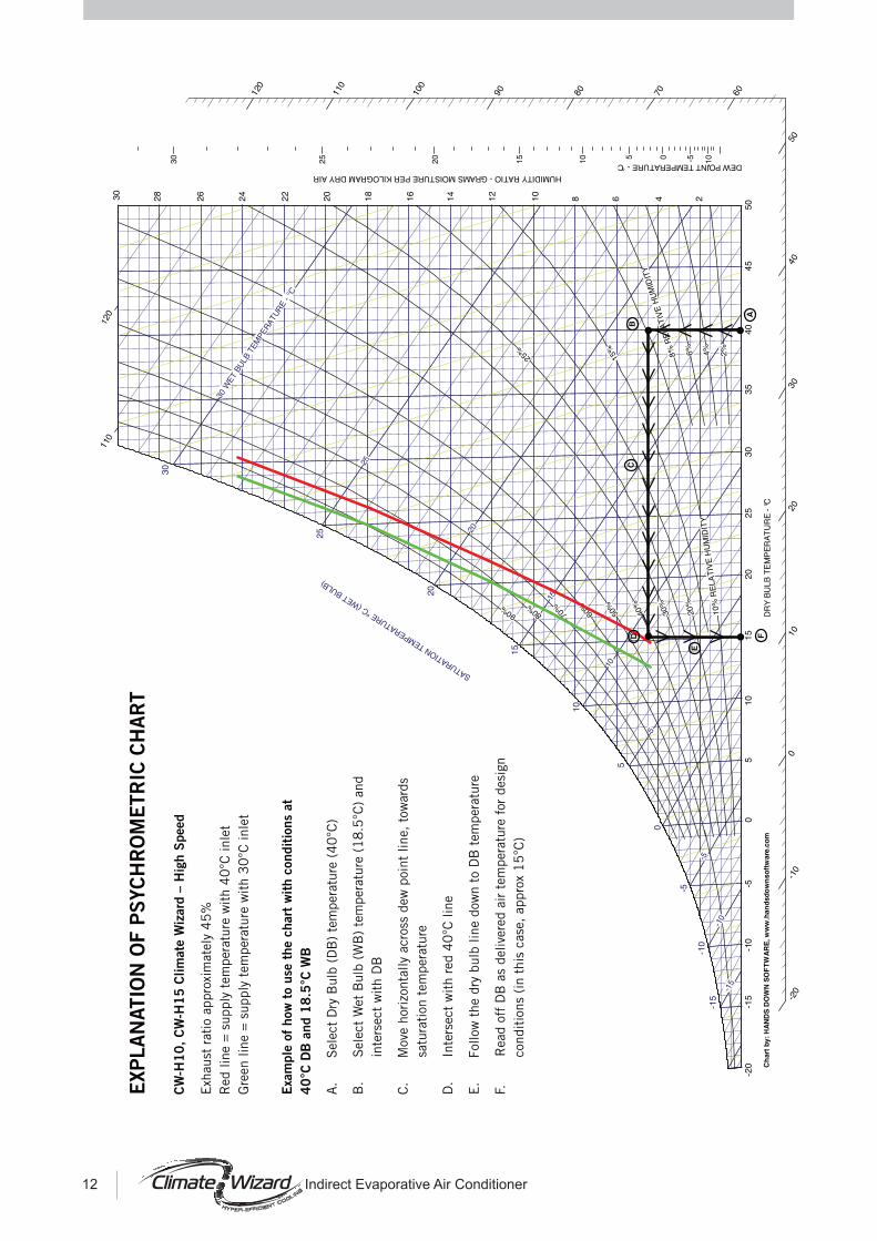
Psychrometric Chart, (Page 12)
WORKED EXAMPLES:
Commercial building inAdelaide,Australia, planning to use Lennox FGM200 RooftopA/C units.Unit specs: 197 kW cooling capacity, input power 66 kW, 35000 cmh airflow. COP = 197 / 66 = 3.0
Total fresh air 25% of 35000 = 8750 cmh = 2430 L/sec. Use 2 x CW-H15Climate 38°C Tdb and 10°C Tdew. CW-H15 Cooling Effect = 30.5 kW; input power = 2 x 1.8 kW,A/C unit load becomes 197 - (2 x 30.5) = 136 kW; hence input power at 3.0 COP = 136/3 = 45 kWTotal system input power = 45 + (2 x 1.8) = 48.6 kWOriginal system power = 66 kW
Supermarket in very hot city in Spain, planning to use Lennox FHK190 RooftopA/C units.Unit specs: 208 kW cooling capacity, input power 75 kW, 33000 cmh airflow COP 208/75 = 2.8
Total fresh air 10% of 33000 = 3300 cmh = 917 L/sec Use CW-H15.Climate 40°C Tdb, and 12°C Tdew. CW-H15 Cooling Effect = 31.6 kW ; input power 1.8kWA/C unit load becomes 208 - 31.6 = 176.4 kW; hence input power at 2.8 COP = 176.4/2.8 = 63 kWTotal system input power = 63 + 1.8 = 64.8 kWOriginal system power = 75 kW
Commercial Offices in Lyon, France, planning to use Lennox FGM200 RooftopA/C units.Unit specs: 197 kW cooling capacity, input power 66 kW, 35000 cmh airflow. COP = 197 / 66 = 3.0
Total fresh air 20% of 35000 = 7000 cmh = 1944 L/sec. Use 2 x CW-H15Climate 34°C Tdb and 11.7°C Tdew. CW-H15 Cooling Effect = 24.5 kW; input power = 2 x 1.8 kWA/C unit load becomes 197 - (2 x 24.5) = 148 kW; hence input power at 3.0 COP = 148/3 = 49.3 kWTotal system input power = 49.3 + (2 x 1.8) = 52.9 kWOriginal system power = 66 kW
Example 1:
Example 2:
Example 3:
Assume 25% fresh air.
Saving = 17.4 kW or about 26%.
Assume 10% fresh air.
Saving = 10.2 kW or about 14%.
Assume 20% fresh air.
Saving = 13.1 kW or about 20%.
8 Indirect Evaporative Air Conditioner

DIMENSIONS & VIEWS
ISOMETRIC
1610mm(63.4”)
TOP
1825mm (71.8”)CW-H15
1230mm (48.4”)CW-H10
SIDE 1985mm (78.2”)(Control Box Handle)
2435mm (95.9”)(Air Filter)
Mounting Plinth1300mm (51.2”)
667mm(26.2”)
REAR
RAIN HOOD FOREXHAUST TRANSITION
Mounting Plinth1206mm (47.5”) (CW-H10)1800mm (70.9”) (CW-H15)
Rain hood (not supplied)(Min. throat radius = 75mm,Max. pressure drop = 20Pa)
Relocate grille torain hood if fitted
SEELEY INTERNATIONAL – APPLICATION GUIDE 9
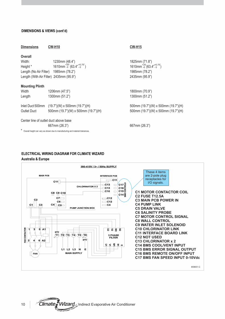
ELECTRICAL WIRING DIAGRAM FOR CLIMATE WIZARD
Australia & Europe
C1 MOTOR CONTACTOR COILC2 FUSE T12.5AC3 MAIN PCB POWER INC4 PUMP LINKC5 DRAIN VALVEC6 SALINITY PROBEC7 MOTOR CONTROL SIGNALC8 WALL CONTROLC9 WATER INLET SOLENOIDC10 CHLORINATOR LINKC11 INTERFACE BOARD LINKC12 NOT USEDC13 CHLORINATOR x 2C14 BMS COOL/VENT INPUTC15 BMS ERROR SIGNAL OUTPUTC16 BMS REMOTE ON/OFF INPUTC17 BMS FAN SPEED INPUT 0-10Vdc
These 4 itemsare 2-pole plugreceptacles for
I/O signals.
859651-C
MAIN PCB
C1
C2
C3 C4 C5
C6
C7
C8 C9 C10
C11C11
C13
C13
C10
C12
C12
C4
C17
C16
C15
C14
3 PHASEFILTER
BM
S C
ON
TR
OL
S
FA
N C
ON
TAC
TO
R
INTERFACE PCB
T1 T2 T3 T4 T5 T6
L1 L2 L3 N E
A1531
2 4 6 A2
U2
V2
W2
N2
U1
V1
W1 E
gn/y
gn/y
CHLORINATOR X 2
MAIN SUPPLY
N1
FAN
380-415V / 3~ / 50Hz SUPPLY
PUMP JUNCTION BOX
Dimensions CW-H10 CW-H15
Width: 1230mm (48.4”) 1825mm (71.8”)
Height * 1610mm (63.4” ) 1610mm (63.4” )
Length (No Air Filter) 1985mm (78.2”) 1985mm (78.2”)
Width 1206mm (47.5”) 1800mm (70.9”)
Length 1300mm (51.2”) 1300mm (51.2”)
Inlet Duct 500mm (19.7”)(W) x 500mm (19.7”)(H) 500mm (19.7”)(W) x 500mm (19.7”)(H)
Outlet Duct 500mm (19.7”)(W) x 500mm (19.7”)(H) 500mm (19.7”)(W) x 500mm (19.7”)(H)
Center line of outlet duct above base
667mm (26.3”) 667mm (26.3”)
*
Overall
Mounting Plinth
Length (With Air Filter) 2435mm (95.9”) 2435mm (95.9”)
Overall height can vary as shown due to manufacturing and material tolerances.
+20-0
+0.75”- 0
+0.75”- 0
+20-0
Indirect Evaporative Air Conditioner10
DIMENSIONS & VIEWS (cont’d)

USA
861371-A
C1 MOTOR CONTACTOR COILC2 FUSE T12.5AC3 MAIN PCB POWER INC4 PUMP LINKC5 DRAIN VALVEC6 SALINITY PROBEC7 MOTOR CONTROL SIGNALC8 WALL CONTROLC9 WATER INLET SOLENOIDC10 CHLORINATOR LINKC11 INTERFACE BOARD LINKC12 NOT USEDC13 CHLORINATOR x 2C14 BMS COOL/VENT INPUTC15 BMS ERROR SIGNAL OUTPUTC16 BMS REMOTE ON/OFF INPUTC17 BMS FAN SPEED INPUT 0-10Vdc
MAIN PCB
230VacINPUT
12VdcOUTPUT
DENOTES CLASS2 CIRCUIT
CLASS 2POWER SUPPLY
MPS-30-12
C1
C2
C3 C4 C5
C6
C7
C8 C9 C10
C11C11
C13
C13
C10
C12
C12
C4
C17
C16
C15
C14
BM
S C
ON
TR
OL
S
FA
N C
ON
TAC
TO
R
INTERFACE PCB
T1 T2 T3 T4 T5 T6 T7
EL3L2L1
A1531
2 4 6 A2
gn/ygn/y
CHLORINATOR X 2
PUMP JUNCTION BOX
MAIN SUPPLY
220-240V / 3~ / 60Hz SUPPLY
FAN
SEELEY INTERNATIONAL – APPLICATION GUIDE 11
ELECTRICAL WIRING DIAGRAM FOR CLIMATE WIZARD (cont’d)
C1 MOTOR CONTACTOR COILC2 FUSE T12.5AC3 MAIN PCB POWER INC4 PUMP LINKC5 DRAIN VALVEC6 SALINITY PROBEC7 MOTOR CONTROL SIGNALC8 WALL CONTROLC9 WATER INLET SOLENOIDC10 CHLORINATOR LINKC11 INTERFACE BOARD LINKC12 NOT USEDC13 CHLORINATOR x 2C14 BMS COOL/VENT INPUTC15 BMS ERROR SIGNAL OUTPUTC16 BMS REMOTE ON/OFF INPUTC17 BMS FAN SPEED INPUT 0-10Vdc
860312-B
MAIN PCB
230VacINPUT
12VdcOUTPUT
DENOTES CLASS2 CIRCUIT
CLASS 2POWER SUPPLY
MPS-30-12
C1
C2
C3 C4 C5
C6
C7
C8 C9 C10
C11C11
C13
C13
C10
C12
C12
C4
C17
C16
C15
C14
100VA TRANSFORMER380-480V TO 230V
BM
S C
ON
TR
OL
S
FA
N C
ON
TAC
TO
R
INTERFACE PCB
T1 T2 T3 T4 T5 T6 T7
EL3L2L1
A1531
2 4 6 A2
gn/ygn/y
CHLORINATOR X 2
PUMP JUNCTION BOX
MAIN SUPPLY
440-480V / 3~ / 60Hz SUPPLY
FAN
38
PRIMARY
0V
0V
115V
115V
373635
SET FOR 480V
34333231
380V 31 - 38400V 32 - 38415V 31 - 37440V 32 - 37460V 32 - 36480V 33 - 36
PHASE TO PHASEPRIMARY VOLTAGE JUMPER BETWEEN
TRANSFORMER SETTING TABLE
12 Indirect Evaporative Air Conditioner

CONTROL SCHEMES:
Local zone control
Control from remote location
Climate Wizard coolers are supplied from the factory with one (1) Wall Control and a 20m control cable. This makes it possible forthe Cooler to be controlled independently and automatically from the zone to which it is delivering cool air.No additional equipment is required. The Wall Control incorporates a thermostat that regulates fan speed to maintain indoortemperature within 0.5 C of the set temperature.
Climate Wizard Coolers are also supplied with input/output connectors to enable the machine to be controlled from an externallocation, including a BMS system
Whatever control option is being used, the inbuilt Climate Wizard water management and fault monitoring features are alwaysfunctional.
The Climate Wizard control scheme incorporates some Parameters that can be altered to other settings if the default settings are notsuitable.
Individual coolers can be controlled completely from within their cooling zone using the Wall Control-thermostat supplied. A 20mconnecting cable, plugged each end is supplied. 40m cables are also available on request. - P/No. 833897Maximum permissible cable length between the Wall Control and the cooler is 40m.
No interconnection between coolers to achieve ‘Group control’ is possible.
Four plug receptacles are provided in theelectrical control enclosure as shown.These are solely for the control of thecooler from a remote location.
These commands may emanate from a purpose built device such as a panel containing switches for Cooler ON-OFF, Pump ON-OFF, a potentiometer for the fan speed control, and a light to display a cooler fault condition. The panel will include its own powersupply to create signals compatible with the Climate Wizard specifications.
Or they may emanate from a BMS (Building Management System). Depending on the type of BMS it may be necessary to providean off-the-shelf Interface Module between the BMS serial bus and the Climate Wizard plug receptacles.
+0
Error SignalThe error signal comprises of a single pole voltage free contact (solid state electronic, not mechanical relay) that closes under faultconditions. The contact is rated at 500mA at 32 volts DC max.In order to use this signal an external voltage must be supplied that will then drive a relay coil or indicator lamp that does not exceedthe above ratings.
R
ERROR SIGNAL
MAX 500mA
MAX 32V DC
+ve
-ve
SEELEY INTERNATIONAL – APPLICATION GUIDE 13

Remote ON-OFF
Group control from BMS
Water management system
Remote ON-OFF function can be achieved regardless of whether the Climate Wizard is controlled from an external source or not. Ifat any time that the cooler is running under its local Wall Control, and a voltage (4-32 VDC) is switched on to the ‘Remote ON / OFF’receptacle the cooler will shut down until the voltage disappears. This condition of being shut down in this way will be evidenced onthe Wall Control by the words ‘Preparing to start’ flashing on the screen.
Any number of Climate Wizard coolers can be controlled as a group through a BMS system.
Parameter A3 - see below
Default setting - Pre-wet cycle enabled
Pre-wet duration 3 minutes
Pre-wet ALWAYS occurs after the power is resumed
Otherwise pre-wet occurs if there has been a tank drain since the Pump last ran
During pre-wet cycle the fan runs on low speed
Wall Control does NOT display ‘Preparing to start’ because the fan is already running
After Pre-wet, fan will resume running at Wall Control setting
When COOL selected, fan and pump will start 30 seconds after water level has reached the bottom probe
After Pre-wet, the pump then cycles continuously: ON for 1 minute
OFF for 8 minutes
Incorporates soft switching to avoid water-hammer
Opens 9 seconds after COOL mode starts (in order to give Drain Valve time to shut)
Remains open until water level reaches top probe
Opens to water entry if water level is below bottom probe
Will also open at anytime that Salinity Control demands fresh water
Pre-wet cycle
only
Pump control
Inlet solenoid valve control
!
!
!
!
!
!
!
!
!
!
!
!
!
!
!
14 Indirect Evaporative Air Conditioner

Water management system (cont’d)
Tank (reservoir) drain valve control
Salinity Control
!
!
!
!
!
!
!
!
!
!
!
!
!
!
!
!
!
!
!
!
!
!
!
!
!
!
Parameter A1 - see below
Parameter A6 - see below
When power switched on Drain Valve opens
Drain Valve remains open until COOL mode selected
When COOL mode selected Drain valve shuts
Drain Valve remains shut, but will open when either:
Auto-drain activated according to time lapse since COOL mode was last switched OFF - set under Parameter A6. Default
time lapse 3 days. Valve remains open until next COOL mode activated.
OR
Salinity Control demands the tank (reservoir) to be drained. Valve remains open until water level falls below bottom probe,
then it immediately shuts again.
OR
Count of number of times the tank is filled from the bottom to the top probe reaches 8 times. Then valve opens until water
level falls below bottom probe, then it immediately shuts again.
Parameter A1 - see below
Parameter A5 - see below
Two modes of Salinity control:
Water conductivity sensing
Water usage sensing
Water Conductivity sensing:
Probes measure water conductivity for 10 seconds within every minute
When conductivity exceeds the upper set point the water inlet solenoid valve is opened to allow fresh water entry.
Monitoring of conductivity is continuous during this cycle.
Inlet solenoid valve remains open until water level reaches top probe, then it closes
If water reaches top probe, but conductivity is still too high, a drain cycle starts
Drain valve opens until water level falls below bottom probe, then valve closes immediately, and inlet solenoid valve opens
to refill the reservoir.
Contains feature that switches to High Sensitivity status when water is very clean (such as rain water) and will sense
conductivity down to 9 uS (about 4ppm)
Water Usage sensing:
Number of times that tank is filled from bottom probe to top probe is counted. When this count reaches 8, a drain cycle is
initiated.
Drain valve opens until water level falls below bottom probe, then valve closes immediately, and inlet solenoid valve opens
to refill the reservoir.
Pumps enabled to run at any time during the salinity drain cycle.
SEELEY INTERNATIONAL – APPLICATION GUIDE 15

Water management system (cont’d)
Chlorinator Control!
!
!
!
The Chlorinator is a pair of specially treated metallic parallel plates. When submerged in water electrical current flowsbetween them, generating Chlorine which cleans the water.There are two (2) sets of Chlorinator plates in the Climate Wizard.Chlorine is known to kill bacteria in water supplies and the Climate Wizard Chlorination system is designed to minimisebacteria levels within the Cooler.Chlorinators active at all times that the Cooler is in COOL mode, AND the water level is above the bottom probe, AND thepumps are not running (8 minutes in every 9 minutes), AND the salinity control is not sensing (50 seconds in every 60seconds).
PARAMETERS
No. DESCRIPTION VALUE DEFAULTA1 Water salinity control method:
A2A3 Pre-wet control:
A4 Wall Control back light:
A5 Conductivity set point:
A6 Tank (reservoir) drain delay:
A7 Auto re-start after Power failure:
A8 Temperature units:
- Conductivity measuring 00 00- Counts low to high probe fills 01Not applicable to Climate Wizard
- No pre-wet 00- Pre-wet 01 01
- Backlight ‘OFF’ 00- Backlight ‘ON’ 01 01
- Normal conductivity - 4275 µS/cm 00 00- Low conductivity - 2305 µS/cm 01
- Instant drain at COOL off 00- Drain 3 hours after COOL off 01- Drain 12 hours after COOL off 02- Drain 3 days after COOL off 03 03
- Requires manual re-start when power OFF 00 00- Auto restart 01
- Display °C 00 00- Display °F 01
16 Indirect Evaporative Air Conditioner

FAULT CODE #1
1 Flash then 2 seconds OFF
TRI-COLOUR LED: This LED indicates the status of the cooler and indicates Fault Codes (if applicable)
RED COLOURED LED: This LED indicates the status of the conductivity measurement circuit and the status of the Salinity ControlMethod
COMMUNICATION FAILURE
Salinity Control Method = Water Manager,
Salinity Control Method = Water Manager,
NORMAL OPERATION NORMAL OPERATION
Wall Control: No valid message for 10 seconds. System shuts down.
Measured conductivity is below the conductivity set point
1 Red Flash then 2seconds OFF
FAULT CODE #2
2 Flashes then 2 secondsOFF
FAILURE TO DETECT WATER ATLOW PROBE
Salinity Control Method = Standard (8 counts of re-fill to highprobe)
Water has 20 minutes to reach the LOW probe when the solenoid valveis on. If it fails to do so the Fan motor and pump shut down and thisFault is activated.
Measured conductivity is above the conductivity set point
2 Red Flashes then 2seconds OFF
FAULT CODE #3
3 Flashes then 2 secondsOFF
FAILURE TO DETECT WATER ATHIGH PROBE
Once water has reached the LOW probe, water has 20 Minutes toreach the HIGH probe. If it fails to do so the Fan motor and pump shutdown and this Fault is activated.
3 Red Flashes then 2seconds OFF
FAULT CODE #4
Continuously ON
FAILURE TO CLEAR LOW PROBESDURING DRAIN
When the drain has opened water has 20 minutes to clear the LOWprobe.
This will occur after a timed Drain delay when thePump has been switched off, or during a Salinity Drain
If it fails to do so the Fan motor and pump shut down and thisFault is activated.
Lower probes are open circuit or conductivity is less than 9uS/cm.
4 Red Flashes then 2seconds OFF
FAULT CODE #5WATER DETECTED AT HIGH PROBEBUT NOT AT LOW
Low probe is dirty or faulty. If it fails to detect, the Fan motor and pumpshut down and this Fault is activated.
FAULT CODE #6FAILURE TO CLEAR HIGH PROBE If after 4 hours of pump running water has not cleared the HIGH probe(i.e. pumps not working), this Fault is activated.
5 Red Flashes then 2seconds OFF
6 Red Flashes then 2seconds OFF
FAULT CODE #7MOTOR ERROR If an Error has occurred in the motor drive circuit.7 Red Flashes then 2seconds OFF
FAULT CODE #8WARM START If the mains input voltage is under 90Vac but not low enough to resetthe PCB, the system switches off the Fan and Pump and indicates thisFault. If the Voltage returns to a usable voltage level without resettingthe PCB a Fault Code #8 is recorded in the system log.
FAULT CODE 'A’CHLORINATOR FAULT. The Chlorinator is Short Circuit, Open Circuit or running in very highsalinity water > 13,000uS. Any of these faults will initiate Fault Code#A. “SERVICE” will be displayed on the Wall Control and Fault Code#A will be indicated on interrogation. The first Fault Code #A will triggera Salinity Drain cycle. If after the Salinity Drain cycle another FaultCode #A occurs, within 15 minutes, the cooler will be disabled untilremedial action is taken.
FAULT CODE 'B’SMART CARD ERROR
10 Red Flashes then2 seconds OFF
11 Red Flashes then2 seconds OFF
2 Green flash then 2seconds OFF
The main program loop is running, no Fault present
The Smart Card is missing or corrupted. Cooler performance isrestricted to minimum Fan Speed.
LED Indicator - Operating and Fault Code DiagnosisThe Red LED (left-hand LED) is used to indicate the condition of water salinity and configuration of the water management system.Tri-Colour LED (right-hand LED) is used as an operational and fault indicator. NOTE: Tri-colour LED double flashing Green (every 2seconds) = Normal Operation
SEELEY INTERNATIONAL – APPLICATION GUIDE 17

879482-J seeleyinternational.com 1501
It is the policy of Seeley International to introduce continual product improvement.Accordingly, specifications are subject to change without notice.
Warranty ServiceAustralia
USA1-300-650-644
Toll Free: 1-800-926-6824All other regions: Please contact your local Climate Wizard distributor.