8086 handout for chapter one and two
TRANSCRIPT
INTEL MICROPROCESSORS 8086/8088
SALIENT FEATURES:
8086 is the first 16-bit microprocessor from INTEL, released in the year 1978 . It is a
40 pin DIP chip based on N-channel, depletion load silicon gate technology(HMOS).
The term 16 bit means that its ALU,its internal registers and most of the instructions are
designed to work with 16 bit binary words.8086 is available at different clock speeds Viz,
5 M.Hz(8086);8M.Hz(8086-2) and 10(8086-1) M.Hz .8086 microprocessor has a 16-bit
data bus and 20-bit address bus. So, it can address any one of 2 20 =1048576=1 mega
byte memory locations. INTEL 8088 has the same ALU ,same registers and same
instruction set as the 8086.But the only difference is 8088 has only 8-bit data bus and
20-bit address bus. Hence the 8088 can only read/write/ports of only 8-bit data at a
time .The 8088 was used as the CPU in the original IBM personal computers [
IBMPC/XT] .The 8086 microprocessor can work in two modes of operations .They are
Minimum mode and Maximum mode. In the minimum mode of operation the
microprocessor do not associate with any co-processors and can not be used for
multiprocessor systems. But in the maximum mode the 8086 can work in multi-
processor or co-processor configuration. This minimum or maximum operations are
decided by the pin MN/ MX(Active low). When this pin is high 8086 operates in
minimum mode otherwise it operates in Maximium mode.
Differences between 8086 and 8088 Microprocessors :
Though the architecture and instruction set of both 8086 and 8088 processors are same,
still we find certain differences between them They are
(i) 8086 has 16-bit data bus lines whereas 8088 has 8-data lines.
(ii) 8086 is available in three clock speds namely 5 M.Hz,8M.Hz(8086-2) and 10 M.Hz
(8086-1) whereas 8088 is available is only available only in two speeds namely
5M.Hz and 8M.Hz
(iii) The memory address space of 8086 is organized as two 512kB banks whereas 8088
memory space is implemented as a single 1MX 8 memory bank.
(iv) 8086 has a 6-byte instruction queue whereas 8088 has a 4 byte instruction queue .
1
The reason for this is that 8088 can fetch only one byte at a time.
(v) In 8086 the memory control pin ( M/ IO) signal is complement of the 8088
equivalent signal(IO/M)
(vi) The 8086 has BHE(Bank high enable whereas 8088 has SSO status signal .
(vii).The byte and word data operations of 8086 are different from 8088.
(viii) 8086 can read or write either 8-bit or 16-bit word at a time ,whereas 8088 can read
only 8-bit data at a time.
(ix) The I/O voltage levels for 8086 are , Vol is measured at 2.5mA and for 8088 it is
measured at 2.0mA.
(x) 8086 draws a maximum supply current of 360 mA and the 8088 draws a maximum
of 340 mA.
ARCHTECTURE OF 8086/8088 :
To improve the performance by implementing the parallel processing concept the CPU
of the 8086 /8088 is divided into two independent sections .They are Bus Interface Unit
(BIU) and Execution Unit.(EI).The BIU sendsout addresses ,fetches instructions ,read
data from ports and memory and writes data to ports
and memory.i.e the BIU handles all transfers data and addresses on the buses required by
the execution Unit . Whereas the Execution Unit decodes the instructions and executes
the instructions
The Execution Unit : The Execution Unit consists of a control system , a 16-bit ALU,
16-bit Flag register and four general purpose registers(AX,BX,CX,DX), pointer registers
(SP,BP) and Index registers(SI,DI) of each 16-bits .
The control circuitry controls the internal operations .The decoder in the execution unit
decodes the instructions fetched from the memory into a series of actions. The ALU can
add ,subtract, perform operations like logical AND,OR,XOR, increment, decrement,
complement ,and shifting the binary numbers.
Bus Interface Unit : The BIU consists of a 6-byte long instruction register called Queue.
And four stack segment registers (ES,CS,SS,DS) , one Instruction Pointer(IP) and an
adder circuit to calculate the 20bit physical address of a location. This bus interface unit
will perform all the external bus operations. They are fetching the instructions from the
memory, read/write data from/into memory or port and also supporting the instruction
2
Queue etc. The BIU fetches up to six instruction bytes from the memory and stores these
pre-fetched bytes in a first –in first out register set called Queue. When the execution unit
is ready for the execution of the instruction ,instead of fetching the byte from the memory
,it reads the byte from the Queue .This will increase the overall speed of
microprocessor .Fetching the next instruction while the current instruction executes is
called pipelining or parallel processing.
Fig.2.Architecture of 8086 Microprocessor
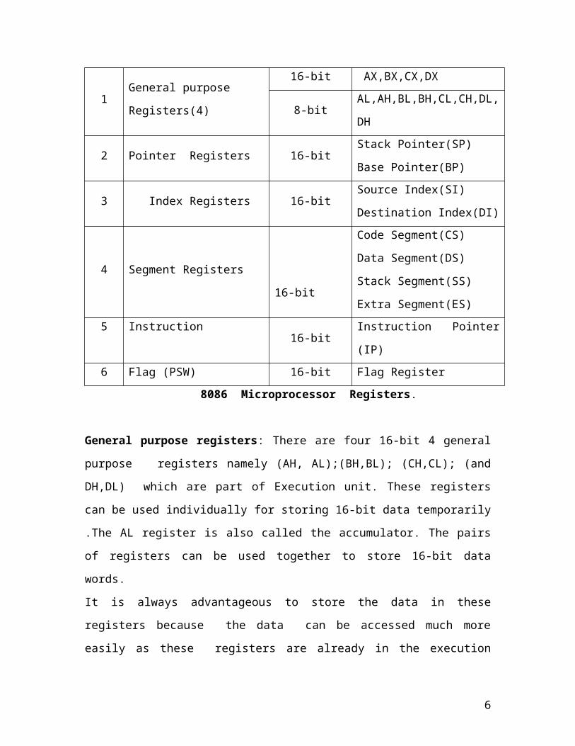
REGISTER ORGANISATION :
The 14 registers of 8086 microprocessor are categorized into four groups. They are
general purpose data registers , Pointer & Index registers , Segment registers and Flag
register as shown in the table below.
3
S.No Type Register width Name of the Registers
1 General purpose Registers(4)16-bit AX,BX,CX,DX
8-bit AL,AH,BL,BH,CL,CH,DL,DH
2 Pointer Registers 16-bitStack Pointer(SP)
Base Pointer(BP)
3 Index Registers 16-bitSource Index(SI)
Destination Index(DI)
4 Segment Registers 16-bit
Code Segment(CS)
Data Segment(DS)
Stack Segment(SS)
Extra Segment(ES)
5 Instruction 16-bit Instruction Pointer (IP)
6 Flag (PSW) 16-bit Flag Register
8086 Microprocessor Registers.
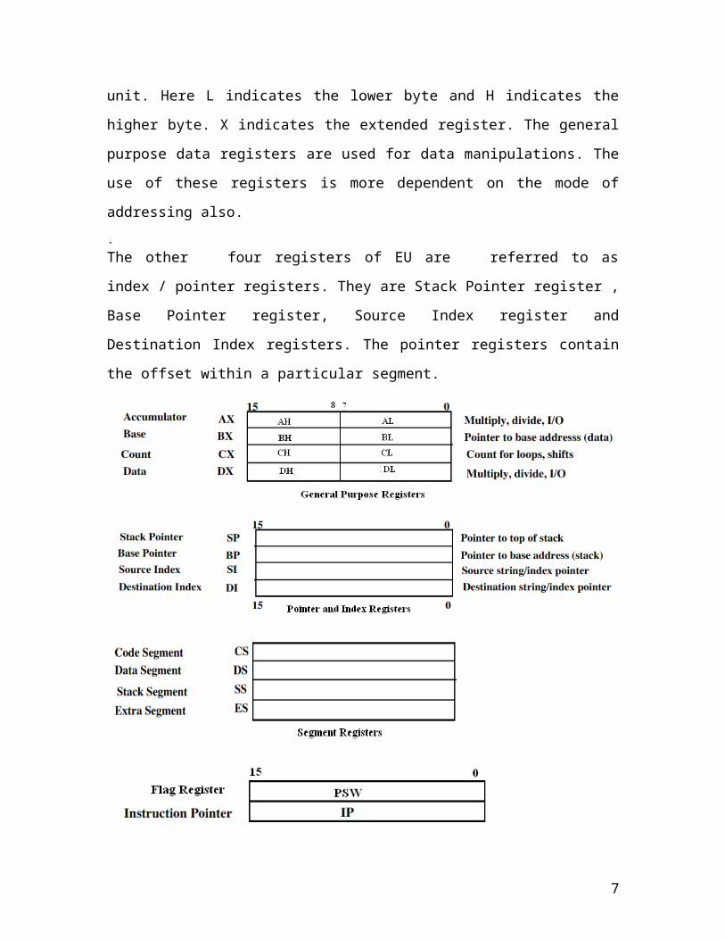
General purpose registers: There are four 16-bit 4 general purpose registers namely
(AH, AL);(BH,BL); (CH,CL); (and DH,DL) which are part of Execution unit. These
registers can be used individually for storing 16-bit data temporarily .The AL register is
also called the accumulator. The pairs of registers can be used together to store 16-bit
data words.
It is always advantageous to store the data in these registers because the data can be
accessed much more easily as these registers are already in the execution unit. Here L
indicates the lower byte and H indicates the higher byte. X indicates the extended
register. The general purpose data registers are used for data manipulations. The use of
these registers is more dependent on the mode of addressing also.
.The other four registers of EU are referred to as index / pointer registers. They are
Stack Pointer register , Base Pointer register, Source Index register and Destination
Index registers. The pointer registers contain the offset within a particular segment.
4
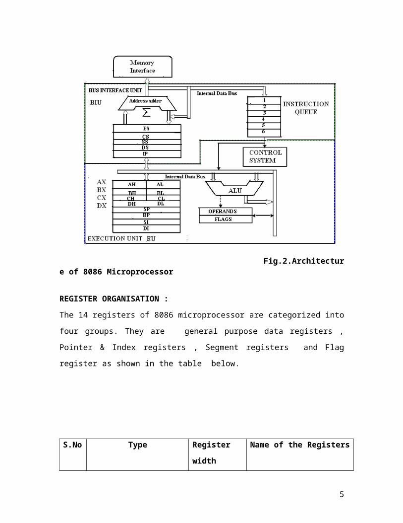
Fig 3. Register Organisation
The BP & SP registers holds the offsets within the data and stack segments respectively.
The Index registers are used as general purpose registers as well as for holding the offset
in case of indexed based and relative indexed addressing modes.The source Index register
is generally used to store the offset of source data in data segment while the Destination
Index register used to store the offset of destination in data or extra segment. These index
registers are specifically used in string manipulations.
Segment Registers :There are four 16-bit segment registers namely code segment
register(CS),Stack segment register(SS),Data segment register(DS) and Extra segment
register(ES).The code segment register is used for addressing the 64kB memory location
in the code segment of the memory ,where the code of the executable program is stored.
Similarly the DS register points to the data segment of the 64kB memory where the data
5
is stored. The Extra segment register also refers to essentially another data segment of
the memory space. The SS register is useful for addressing stack segment of memory. So,
the CS,DS,SS and ES segment registers respectively contains the segment addresses for
the code, data, stack and extra segments of the memory.
Instruction Pointer Register: It is a 16-bit register which always points to the next
instruction to be executed within the currently executing code segment. So, this register
contains the 16-bit offset address pointing to the next instruction code within the 64kB of
the code segment area. Its content is automatically incremented as the execution of the
next instruction takes place.
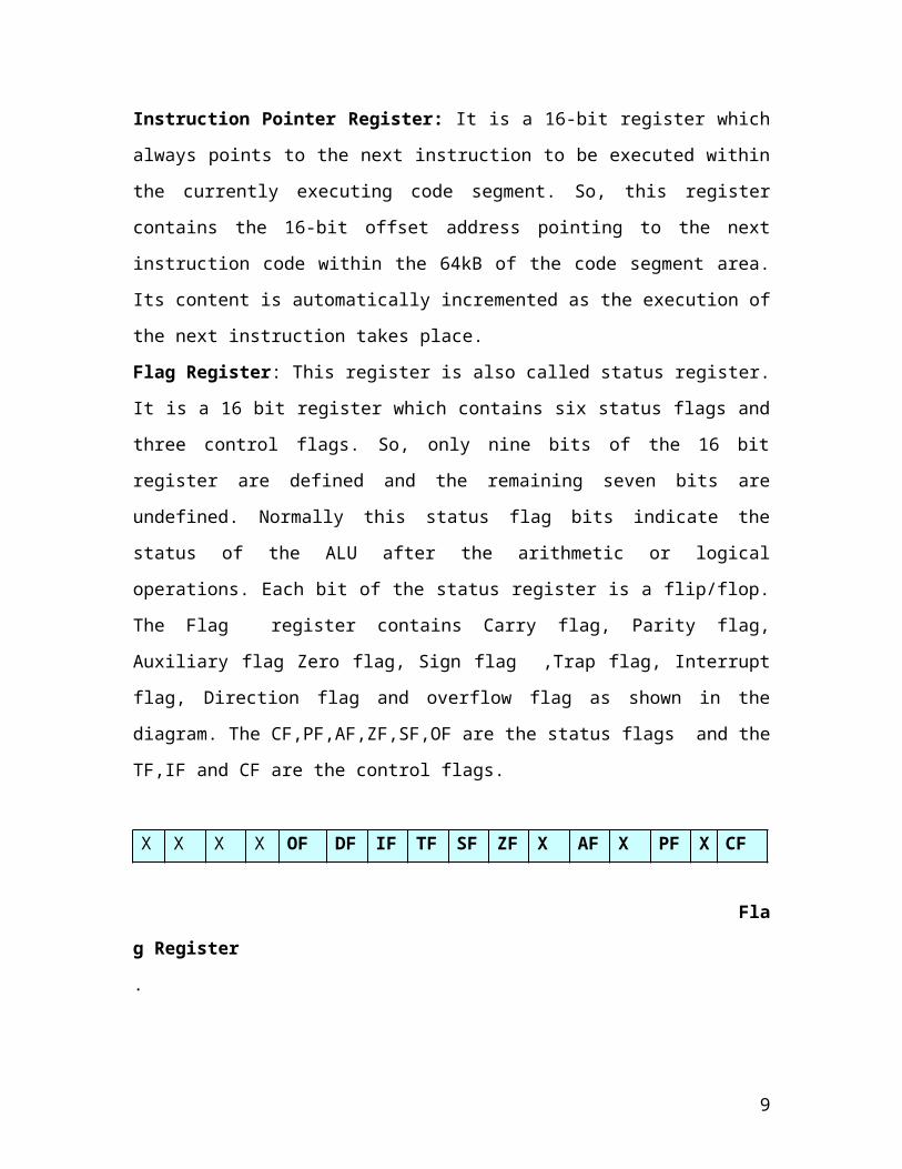
Flag Register: This register is also called status register. It is a 16 bit register which
contains six status flags and three control flags. So, only nine bits of the 16 bit register
are defined and the remaining seven bits are undefined. Normally this status flag bits
indicate the status of the ALU after the arithmetic or logical operations. Each bit of the
status register is a flip/flop. The Flag register contains Carry flag, Parity flag, Auxiliary
flag Zero flag, Sign flag ,Trap flag, Interrupt flag, Direction flag and overflow flag as
shown in the diagram. The CF,PF,AF,ZF,SF,OF are the status flags and the TF,IF and
CF are the control flags.
X X X X OF DF IF TF SF ZF X AF X PF X CF
Flag Register
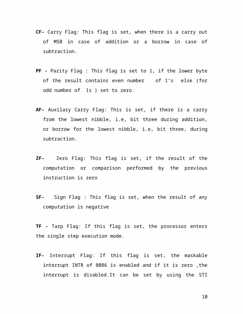
.CF- Carry Flag: This flag is set, when there is a carry out of MSB in case of addition or a
borrow in case of subtraction.
PF - Parity Flag : This flag is set to 1, if the lower byte of the result contains even
number of 1’s else (for odd number of 1s ) set to zero.
AF- Auxilary Carry Flag: This is set, if there is a carry from the lowest nibble, i.e, bit
three during addition, or borrow for the lowest nibble, i.e, bit three, during
subtraction.
6
ZF- Zero Flag: This flag is set, if the result of the computation or comparison performed
by the previous instruction is zero
SF- Sign Flag : This flag is set, when the result of any computation is negative
TF - Tarp Flag: If this flag is set, the processor enters the single step execution mode.
IF- Interrupt Flag: If this flag is set, the maskable interrupt INTR of 8086 is enabled and
if it is zero ,the interrupt is disabled.It can be set by using the STI instruction and can
be cleared by executing CLI instruction.
DF- Direction Flag: This is used by string manipulation instructions. If this flag bit is ‘0’,
the string is processed beginning from the lowest address to the highest address, i.e.,
auto incrementing mode. Otherwise, the string is processed from the highest address
towards the lowest address, i.e., auto incrementing mode.
OF- Over flow Flag: This flag is set, if an overflow occurs, i.e, if the result of a signed
operation is large enough to accommodate in a destination register. The result is of
more than 7-bits in size in case of 8-bit signed operation and more than 15-bits in size
in case of 16-bit sign operations, then the overflow will be set.
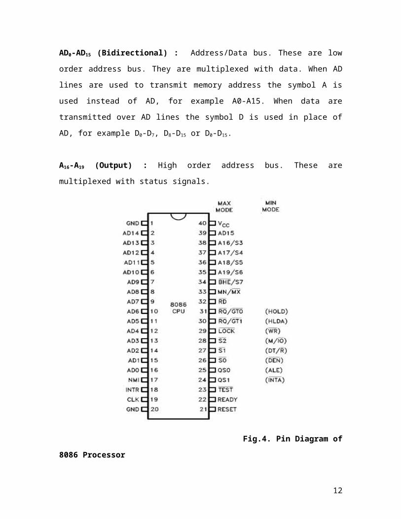
8086 PIN DIAGRAM – PIN DESCRIPTION
Intel 8086 is a 16-bit HMOS microprocessor. It is available in 40 pin DIP chip. It uses a
5V d.c. supply for its operation. The 8086 uses 20-line address bus. It uses a 16-line data
bus. The 20 lines of the address bus operate in multiplexed mode. The 16-low order
address bus lines are multiplexed with data and 4 high-order address bus lines are
multiplexed with status signals. The pin diagram of Intel 8086 is shown in Fig.4.
AD0-AD15 (Bidirectional) : Address/Data bus. These are low order address bus. They
are multiplexed with data. When AD lines are used to transmit memory address the
7
symbol A is used instead of AD, for example A0-A15. When data are transmitted over
AD lines the symbol D is used in place of AD, for example D0-D7, D8-D15 or D0-D15.
A16-A19 (Output) : High order address bus. These are multiplexed with status signals.
Fig.4. Pin Diagram of 8086 Processor
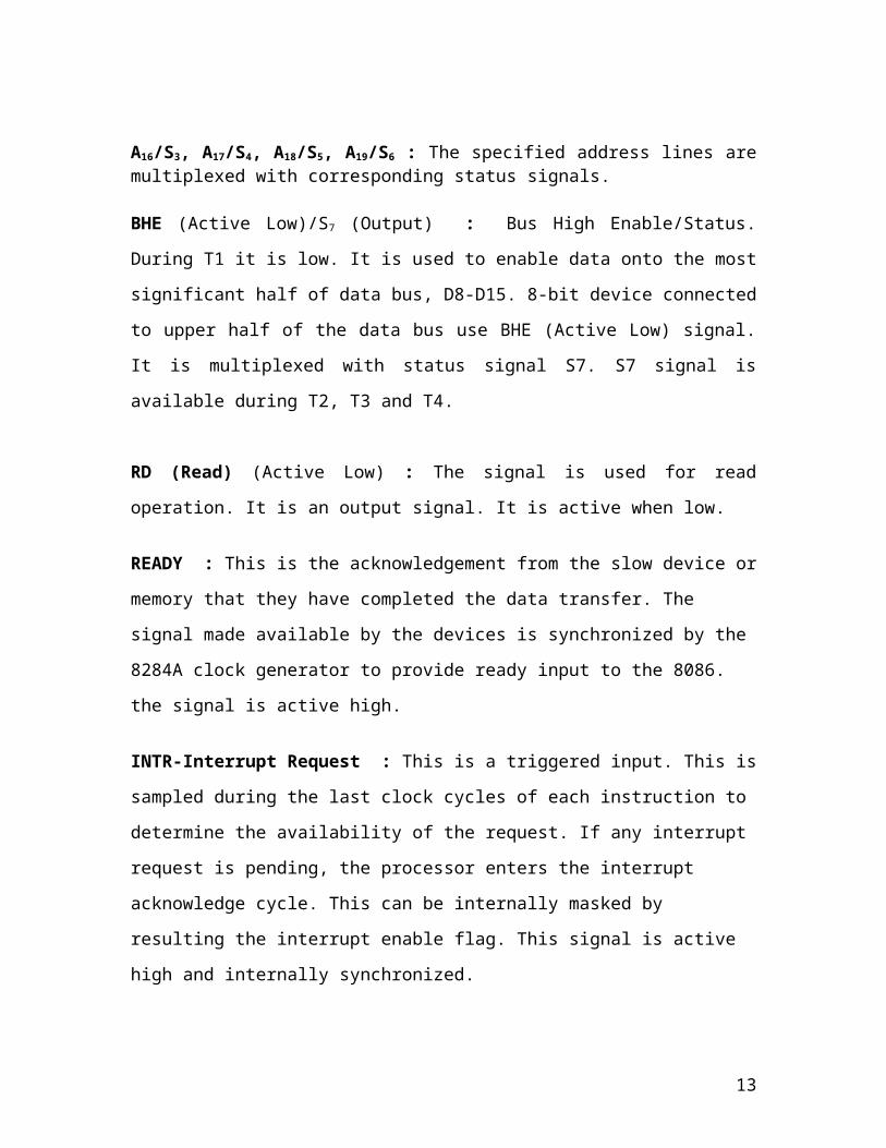
A16/S3, A17/S4, A18/S5, A19/S6 : The specified address lines are multiplexed with corresponding status signals.
BHE (Active Low)/S7 (Output) : Bus High Enable/Status. During T1 it is low. It is used
to enable data onto the most significant half of data bus, D8-D15. 8-bit device connected
to upper half of the data bus use BHE (Active Low) signal. It is multiplexed with status
signal S7. S7 signal is available during T2, T3 and T4.
8
RD (Read) (Active Low) : The signal is used for read operation. It is an output signal. It
is active when low.
READY : This is the acknowledgement from the slow device or memory that they have
completed the data transfer. The signal made available by the devices is synchronized by
the 8284A clock generator to provide ready input to the 8086. the signal is active high.
INTR-Interrupt Request : This is a triggered input. This is sampled during the last
clock cycles of each instruction to determine the availability of the request. If any
interrupt request is pending, the processor enters the interrupt acknowledge cycle. This
can be internally masked by resulting the interrupt enable flag. This signal is active high
and internally synchronized.
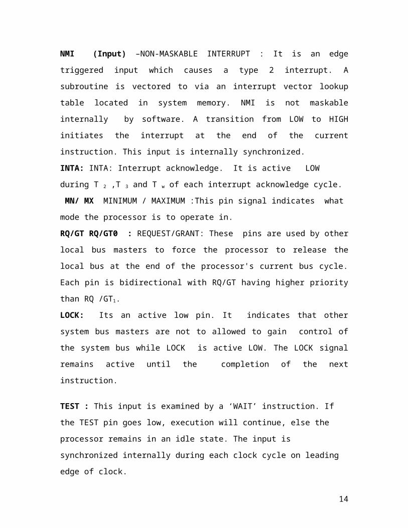
NMI (Input) –NON-MASKABLE INTERRUPT : It is an edge triggered input which
causes a type 2 interrupt. A subroutine is vectored to via an interrupt vector lookup table
located in system memory. NMI is not maskable internally by software. A transition
from LOW to HIGH initiates the interrupt at the end of the current instruction. This input
is internally synchronized.
INTA: INTA: Interrupt acknowledge. It is active LOW during T 2 ,T 3 and T w of each
interrupt acknowledge cycle.
MN/ MX MINIMUM / MAXIMUM :This pin signal indicates what mode the
processor is to operate in.
RQ/GT RQ/GT0 : REQUEST/GRANT: These pins are used by other local bus masters
to force the processor to release the local bus at the end of the processor's current bus
cycle. Each pin is bidirectional with RQ/GT having higher priority than RQ /GT1.
LOCK: Its an active low pin. It indicates that other system bus masters are not to
allowed to gain control of the system bus while LOCK is active LOW. The LOCK
signal remains active until the completion of the next instruction.
TEST : This input is examined by a ‘WAIT’ instruction. If the TEST pin goes low,
execution will continue, else the processor remains in an idle state. The input is
synchronized internally during each clock cycle on leading edge of clock.
9
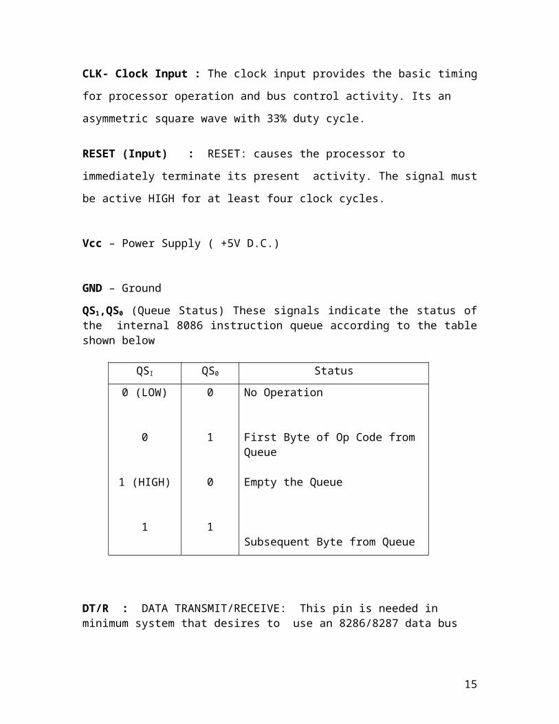
CLK- Clock Input : The clock input provides the basic timing for processor operation
and bus control activity. Its an asymmetric square wave with 33% duty cycle.
RESET (Input) : RESET: causes the processor to immediately terminate its present
activity. The signal must be active HIGH for at least four clock cycles.
Vcc – Power Supply ( +5V D.C.)
GND – Ground
QS1,QS0 (Queue Status) These signals indicate the status of the internal 8086 instruction queue according to the table shown below
QSI QS0 Status
0 (LOW)
0
1 (HIGH)
1
0
1
0
1
No Operation
First Byte of Op Code from Queue
Empty the Queue
Subsequent Byte from Queue
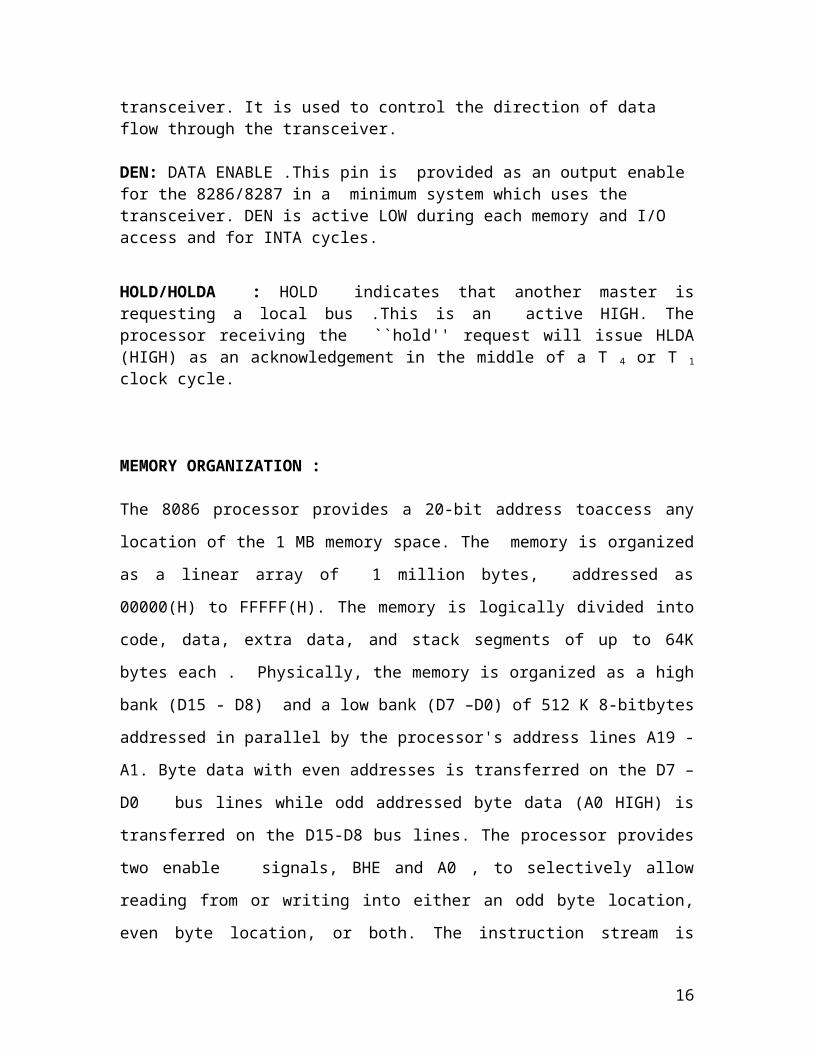
DT/R : DATA TRANSMIT/RECEIVE: This pin is needed in minimum system that desires to use an 8286/8287 data bus transceiver. It is used to control the direction of data flow through the transceiver.
DEN: DATA ENABLE .This pin is provided as an output enable for the 8286/8287 in a minimum system which uses the transceiver. DEN is active LOW during each memory and I/O access and for INTA cycles.
HOLD/HOLDA : HOLD indicates that another master is requesting a local bus .This is an active HIGH. The processor receiving the ``hold'' request will issue HLDA (HIGH) as an acknowledgement in the middle of a T 4 or T 1 clock cycle.
MEMORY ORGANIZATION :
10
The 8086 processor provides a 20-bit address toaccess any location of the 1 MB memory
space. The memory is organized as a linear array of 1 million bytes, addressed as
00000(H) to FFFFF(H). The memory is logically divided into code, data, extra data, and
stack segments of up to 64K bytes each . Physically, the memory is organized as a high
bank (D15 - D8) and a low bank (D7 –D0) of 512 K 8-bitbytes addressed in parallel by
the processor's address lines A19 -A1. Byte data with even addresses is transferred on the
D7 – D0 bus lines while odd addressed byte data (A0 HIGH) is transferred on the D15-
D8 bus lines. The processor provides two enable signals, BHE and A0 , to selectively
allow reading from or writing into either an odd byte location, even byte location, or
both. The instruction stream is fetched from memory as words and is addressed internally
by the processor to the byte level as necessary.
INTERRUPTS :
An interrupt to the microprocessor is defined as that which disturbs the normal execution
of a program . Broadly the interrupts are divided into two types. They are external
hardware Interrupts and internal (Software) Interrupts . The hardware interrupts are
classified as non-maskable and maskable interrupts. The hardware interrupt is caused by
any peripheral device by sending a signal through a specified pin to the microprocessor.
Whereas internal interrupts are initiated by the state of the CPU (e.g. divide by zero error)
or by an instruction. So, the software interrupt is one which interrupts the normal
execution of a program of the microprocessor. The 8086 has two hardware interrupt pins
namely NMI and INTR.In the two ,the NMI is a non-maskable interrupt and the INTR
interrupt request is a maskable interrupt which has lower proirity .The third pin
associated with the hardware interrupts are the INTA called interrupt acknowledge.
NMI : The processor provides a single non-maskable interrupt pin (NMI) which has
higher priority than the maskable interrupt request pin (INTR). A typical use would be to
activate a power failure routine. The NMI is edge-triggered on a LOW-to-HIGH
transition. The activation of this pin causes a type 2 interrupt.
11
INTR: The 8086 provides a single interrupt request input (INTR) which can be masked
internally by software with the resetting of the interrupt enable FLAG status bit. The
interrupt request signal is level triggered. It is internally synchronized during each clock
cycle on the high-going edge of CLK. To be responded to, INTR must be present (HIGH)
during the clock period preceding the end of the current instruction or the end of a whole
move for a block type instruction.
Software Interrupts: Coming to the software interrupts , 8086 can generate 256
interrupt types through the instruction INT n .Any of the 256 interrupt types can be
generated by specifying the interrupt type after INT instruction . For example INT 33
will cause type 33 interrupt.
I k Bytes of memory from 00000H to 003FF H is set aside to store
the starting address of the Interrupt service sub-routine(ISS) programs in an 8086 based
systems. To store the starting address of the each ISS , four bytes of memory space is
required.Two bytes are for storing CS value and two bytes for IP value. The starting
address of an ISS stored in 1kB of memory space is called Interrupt pointer or Interrupt
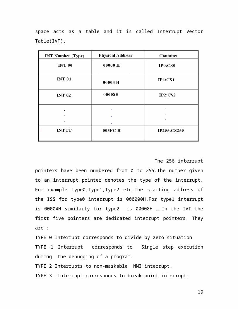
vector.The 1kB memory space acts as a table and it is called Interrupt Vector
Table(IVT).
12
The 256 interrupt pointers have been numbered from 0 to 255.The
number given to an interrupt pointer denotes the type of the interrupt. For example
Type0,Type1,Type2 etc…The starting address of the ISS for type0 interrupt is
000000H.For type1 interrupt is 00004H similarly for type2 is 00008H ……In the IVT
the first five pointers are dedicated interrupt pointers. They are :
TYPE 0 Interrupt corresponds to divide by zero situation
TYPE 1 Interrupt corresponds to Single step execution during the debugging of a
program.
TYPE 2 Interrupts to non-maskable NMI interrupt.
TYPE 3 :Interrupt corresponds to break point interrupt.
TYPE 4 Interrupt corresponds to Overflow interrupt.
The Interrupts from Type 5 to Type 31 are reserved for other advanced
microprocessors,and from 32 to Type 255 are available for hardware and software
interrupts.
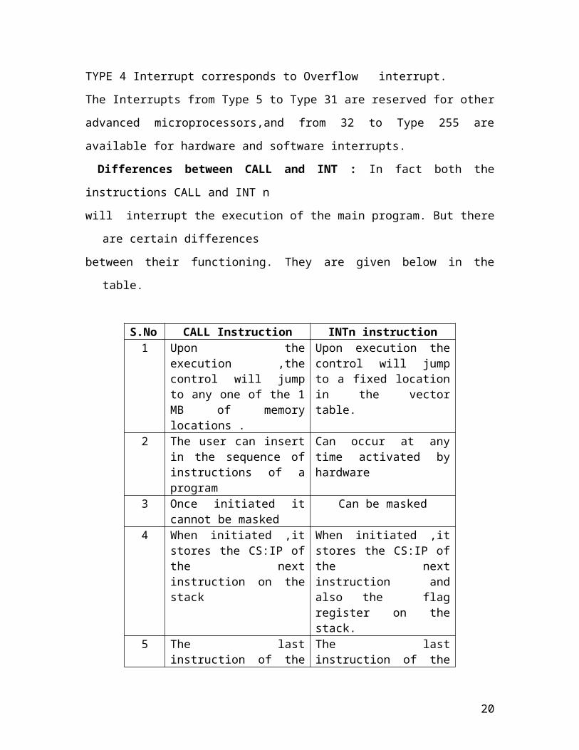
Differences between CALL and INT : In fact both the instructions CALL and INT n
will interrupt the execution of the main program. But there are certain differences
between their functioning. They are given below in the table.
S.No CALL Instruction INTn instruction1 Upon the execution ,the
control will jump to any one of the 1 MB of memory locations .
Upon execution the control will jump to a fixed location in the vector table.
2 The user can insert in the sequence of instructions of a program
Can occur at any time activated by hardware
3 Once initiated it cannot be masked
Can be masked
4 When initiated ,it stores the CS:IP of the next instruction on the stack
When initiated ,it stores the CS:IP of the next instruction and also the flag register on the stack.
5 The last instruction of the subroutine will be RET
The last instruction of the ISS will be IRET
13
ADDRESSING MODES :
The different ways in which a source operand is denoted in an instruction are known as
the addressing modes. There are 8 different addressing modes in 8086 programming.
They are
1. Immediate addressing mode
2. Register addressing mode
3. Direct addressing mode
4. Register indirect addressing mode
5. Based addressing mode
6. Indexed addressing mode.
7. Based indexed addressing mode
8. Based, Indexed with displacement.
Immediate addressing mode: The addressing mode in which the data operand is a part of the instruction itself is called Immediate addressing mode.
For Ex: MOV CX, 4847 H ADD AX, 2456 H MOV AL, FFH
Register addressing mode : Register addressing mode means, a register is the source of an operand for an instruction.
For Ex : MOV AX, BX copies the contents of the 16-bit BX register into the 16-bit AX register. EX : ADD CX,DX
Direct addressing mode: The addressing mode in which the effective address of the
memory location at which the data operand is stored is given in the instruction.i.e the
effective address is just a 16-bit number is written directly in the instruction.
For Ex: MOV BX, [1354H] MOV BL,[0400H]
. The square brackets around the 1354 H denotes the contents of the memory location.
When executed, this instruction will copy the contents of the memory location into BX
14
register. This addressing mode is called direct because the displacement of the operand
from the segment base is specified directly in the instruction.
Register indirect addressing mode: Register indirect addressing allows data to be
addressed at any memory location through an offset address held in any of the following
registers: BP, BX, DI and SI.
Ex: MOV AX, [BX]. Suppose the register BX contains 4675H ,the contents of the 4675 H are moved to AX. ADD CX,{BX}
Based addressing mode: The offset address of the operand is given by the sum of
contents of the BX or BP registers and an 8-bit or 16-bit displacement.
Ex: MOV DX, [BX+04]
ADD CL,[BX+08]
Indexed Addressing mode: The operands offset address is found by adding the
contents of SI or DI register and 8-bit or 16-bit displacements.
Ex: MOV BX,[SI+06] ADD AL,[DI+08]
Based -index addressing mode: The offset address of the operand is computed by summing the base register to the contents of an Index register.
Ex: ADD CX,[BX+SI]
MOV AX,[BX+DI]
Based Iindexd with displacement mode: The operands offset is computed by adding the base register contents, an Index registers contents and 8 or 16-bit displacement.Ex : MOV AX,[BX+DI+08] ADD CX,[BX+SI+16]
INSTRUCTION SET OF 8086/8088
The 8086 microprocessor supports 6 types of Instructions. They are
1. Data transfer instructions
15
2. Arithmetic instructions
3. Bit manipulation instructions
4. String instructions
5. Program Execution Transfer instructions (Branch & loop Instructions)
6. Processor control instructions
1. Data Transfer instructions :These instructions are used to transfer the data from source operand to destination operand. All the store, move, load, exchange ,input and output instructions belong to to this group. General purpose byte or word transfer instructions:MOV : Copy byte or word from specified source to specified destinationPUSH : Push the specified word to top of the stackPOP : Pop the word from top of the stack to the specified locationPUSHA : Push all registers to the stackPOPA : Pop the words from stack to all registersXCHG : Exchange the contents of the specified source and destination operands one of which may be a register or memory location.XLAT : Translate a byte in AL using a table in memory
Simple input and output port transfer instructions
1. IN : Reads a byte or word from specified port to the accumulator2. OUT : Sends out a byte or word from accumulator to a specified port
Special address transfer instructions1. LEA : Load effective address of operand into specified register2. LDS : Load DS register and other specified register from memory3. LES : Load ES register and other specified register from memory.
Flag transfer registers
1. LAHF : Load AH with the low byte of the flag register2. SAHF : Store AH register to low byte of flag register3. PUSHF : Copy flag register to top of the stack 4. POPF : Copy word at top of the stack to flag register
2. Arithmetic instructions : These instructions are used to perform various mathematical operations like addition, subtraction, multiplication and division etc….
Addition instructions
1.ADD : Add specified byte to byte or word to word 2.ADC : Add with carry 3.INC : Increment specified byte or specified word by 1
16
4.AAA : ASCII adjust after addition
5.DAA : Decimal (BCD) adjust after addition
Subtraction instructions1. SUB : Subtract byte from byte or word from word2. SBB : Subtract with borrow3. DEC : Decrement specified byte or word by 14. NEG : Negate or invert each bit of a specified byte or word and add 1(2’s
complement)5. CMP : Compare two specified byte or two specified words6. AAS : ASCII adjust after subtraction7. DAS : Decimal adjust after subtraction
Multiplication instructions1. MUL : Multiply unsigned byte by byte or unsigned word or word.2. IMUL : Multiply signed bye by byte or signed word by word3. AAM : ASCII adjust after multiplication
Division instructions1. DIV : Divide unsigned word by byte or unsigned double word by word2. IDIV : Divide signed word by byte or signed double word by word3. AAD : ASCII adjust after division4. CBW : Fill upper byte of word with copies of sign bit of lower byte5. CWD : Fill upper word of double word with sign bit of lower word.
3. Bit Manipulation instructions : These instructions include logical , shift and rotate instructions in which a bit of the data is involved. Logical instructions
1. NOT :Invert each bit of a byte or word. 2. AND : ANDing each bit in a byte or word with the corresponding bit in
another byte or word.3. OR : ORing each bit in a byte or word with the corresponding bit in another byte or word.3. XOR : Exclusive OR each bit in a byte or word with the corresponding bit in
another byte or word. 4. TEST :AND operands to update flags, but don’t change operands.
Shift instructions1. SHL/SAL : Shift bits of a word or byte left, put zero(S) in LSBs.2. SHR : Shift bits of a word or byte right, put zero(S) in MSBs.3. SAR : Shift bits of a word or byte right, copy old MSB into new MSB.
Rotate instructions1. ROL : Rotate bits of byte or word left, MSB to LSB and to Carry Flag [CF]2. ROR : Rotate bits of byte or word right, LSB to MSB and to Carry Flag [CF]3. RCR :Rotate bits of byte or word right, LSB TO CF and CF to MSB4. RCL :Rotate bits of byte or word left, MSB TO CF and CF to LSB
17
4. String instructionsA string is a series of bytes or a series of words in sequential memory locations. A string often consists of ASCII character codes.
1. REP : An instruction prefix. Repeat following instruction until CX=02. REPE/REPZ : Repeat following instruction until CX=0 or zero flag ZF=13. REPNE/REPNZ : Repeat following instruction until CX=0 or zero flag ZF=14. MOVS/MOVSB/MOVSW: Move byte or word from one string to another5. COMS/COMPSB/COMPSW: Compare two string bytes or two string words6. INS/INSB/INSW: Input string byte or word from port7. OUTS/OUTSB/OUTSW : Output string byte or word to port8. SCAS/SCASB/SCASW: Scan a string. Compare a string byte with a byte in AL
or a string word with a word in AX9. LODS/LODSB/LODSW: Load string byte in to AL or string word into AX
5.Program Execution Transfer instructions These instructions are similar to branching or looping instructions. These instructions include conditional & unconditional jump or loop instructions.
Unconditional transfer instructions1. CALL : Call a procedure, save return address on stack2. RET : Return from procedure to the main program.3. JMP : Goto specified address to get next instruction
Conditional transfer instructions
1. JA/JNBE : Jump if above / jump if not below or equal2. JAE/JNB : Jump if above /jump if not below3. JBE/JNA : Jump if below or equal/ Jump if not above4. JC : jump if carry flag CF=15. JE/JZ : jump if equal/jump if zero flag ZF=16. JG/JNLE : Jump if greater/ jump if not less than or equal7. JGE/JNL : jump if greater than or equal/ jump if not less than8. JL/JNGE : jump if less than/ jump if not greater than or equal9. JLE/JNG : jump if less than or equal/ jump if not greater than10. JNC : jump if no carry (CF=0)11. JNE/JNZ : jump if not equal/ jump if not zero(ZF=0)12. JNO : jump if no overflow(OF=0)13. JNP/JPO : jump if not parity/ jump if parity odd(PF=0)14. JNS : jump if not sign(SF=0)15. JO : jump if overflow flag(OF=1)16. JP/JPE : jump if parity/jump if parity even(PF=1)17. JS : jump if sign(SF=1)
6.Iteration control instructions
18
These instructions are used to execute a series of instructions for certain number of times.
1. LOOP :Loop through a sequence of instructions until CX=02. LOOPE/LOOPZ : Loop through a sequence of instructions while ZF=1 and
CX = 03. LOOPNE/LOOPNZ : Loop through a sequence of instructions while ZF=0 and
CX =0 4. JCXZ : jump to specified address if CX=0
7. Interrupt instructions 1. INT : Interrupt program execution, call service procedure2. INTO : Interrupt program execution if OF=13. IRET : Return from interrupt service procedure to main program
8.High level language interface instructions1. ENTER : enter procedure2. LEAVE :Leave procedure3. BOUND : Check if effective address within specified array bounds
9.Processor control instructionsFlag set/clear instructions
1. STC : Set carry flag CF to 12. CLC : Clear carry flag CF to 03. CMC : Complement the state of the carry flag CF4. STD : Set direction flag DF to 1 (decrement string pointers)5. CLD : Clear direction flag DF to 06. STI : Set interrupt enable flag to 1(enable INTR input)7. CLI : Clear interrupt enable Flag to 0 (disable INTR input)
10. External Hardware synchronization instructions1. HLT : Halt (do nothing) until interrupt or reset2. WAIT : Wait (Do nothing) until signal on the test pin is low3. ESC : Escape to external coprocessor such as 8087 or 80894. LOCK : An instruction prefix. Prevents another processor from taking the bus while the
adjacent instruction executes.11. No operation instruction
1. NOP : No action except fetch and decode
ASSEMBLER DIRECTIVES :
Assembler directives are the directions to the assembler which indicate how an
operand or section of the program is to be processed. These are also called pseudo
operations which are not executable by the microprocessor. The various directives are
explained below.
19
1. ASSUME : The ASSUME directive is used to inform the assembler the name of the
logical segment it should use for a specified segment.
Ex: ASSUME DS: DATA tells the assembler that for any program instruction which
refers to the data segment ,it should use the logical segment called DATA.
2.DB -Define byte. It is used to declare a byte variable or set aside one or more storage
locations of type byte in memory.
For example, CURRENT_VALUE DB 36H tells the assembler to reserve 1 byte of
memory for a variable named CURRENT_ VALUE and to put the value 36 H in that
memory location when the program is loaded into RAM .
3. DW -Define word. It tells the assembler to define a variable of type word or to reserve
storage locations of type word in memory.
4. DD(define double word) :This directive is used to declare a variable of type double
word or restore memory locations which can be accessed as type double word.
5.DQ (define quadword) :This directive is used to tell the assembler to declare a
variable 4 words in length or to reserve 4 words of storage in memory .
6.DT (define ten bytes):It is used to inform the assembler to define a variable which is
10 bytes in length or to reserve 10 bytes of storage in memory.
7. EQU –Equate It is used to give a name to some value or symbol. Every time the
assembler finds the given name in the program, it will replace the name with the value or
symbol we have equated with that name
8.ORG -Originate : The ORG statement changes the starting offset address of the data.
It allows to set the location counter to a desired value at any point in the program.For
example the statement ORG 3000H tells the assembler to set the location counter to
3000H.
9 .PROC- Procedure: It is used to identify the start of a procedure. Or subroutine.
10. END- End program .This directive indicates the assembler that this is the end of the
program module.The assembler ignores any statements after an END directive.
11. ENDP- End procedure: It indicates the end of the procedure (subroutine) to the
assembler.
12.ENDS-End Segment: This directive is used with the name of the segment to indicate
the end of that logical segment.
20
Ex: CODE SEGMENT : Start of logical segment containing code
CODE ENDS : End of the segment named CODE.
ASSEMBLY LANGUAGE DEVELOPMENT TOOLS:
To develop an assembly language program we need certain program
development tools .The various development tools required for 8086 programming are
explained below.
1. Editor : An Editor is a program which allows us to create a file containing the
assembly language statements for the program. Examples of some editors are PC write
Wordstar. As we type the program the editor stores the ACSII codes for the letters and
numbers in successive RAM locations. If any typing mistake is done editor will alert us
to correct it. If we leave out a program statement an editor will let you move everything
down and insert a line. After typing all the program we have to save the program for a
hard disk. This we call it as source file. The next step is to process the source file with an
assembler. While using TASM or MASM we should give a file name and
extension .ASM.
Ex: Sample. asm
2.Assembler : An Assembler is used to translate the assembly language mnemonics into
machine language( i.e binary codes). When you run the assembler it reads the source file
of your program from where you have saved it. The assembler generates two files . The
first file is the Object file with the extension .OBJ. The object file consists of the binary
codes for the instructions and information about the addresses of the instructions. After
further processing, the contents of the file will be loaded in to memory and run. The
second file is the assembler list file with the extension .LST.
3. Linker : A linker is a program used to connect several object files into one large
object file. While writing large programs it is better to divide the large program into
smaller modules. Each module can be individually written, tested and debugged. Then all
the object modules are linked together to form one, functioning program. These object
modules can also be kept in library file and linked into other programs as needed. A
linker produces a link file which contains the binary codes for all the combined modules.
21
The linker also produces a link map file which contains the address information about the
linked files. The linkers which come with TASM or MASM assemblers produce link files
with the .EXE extension.
4.Locator : A locator is a program used to assign the specific addresses of where the
segments of object code are to be loaded into memory. A locator program called
EXE2BIN comes with the IBM PC Disk Operating System (DOS). EXE2BIN converts
a .EXE file to a .BIN file which has physical addresses.
5. Debugger: A debugger is a program which allows to load your object code program
into system memory, execute the program, and troubleshoot or debug it. The debugger
allows to look into the contents of registers and memory locations after the program
runs. We can also change the contents of registers and memory locations and rerun the
program. Some debuggers allows to stop the program after each instruction so that you
can check or alter memory and register contents. This is called single step debug. A
debugger also allows to set a breakpoint at any point in the program. If we insert a break
point , the debugger will run the program up to the instruction where the breakpoint is
put and then stop the execution.
6. Emulator: An emulator is a mixture of hard ware and software. It is usually used to
test and debug the hardware and software of an external system such as the prototype of a
microprocessor based instrument.
-----------------x------------------
22
23