802.3ba copper cable assembly baseline proposal
TRANSCRIPT
802.3bz –Link Segment Characteristics
802.3bz Link Segment Considerations Waikola, HIJuly 2015
Chris DiMinicoMC Communications/[email protected]
1
802.3bz –Link Segment Characteristics
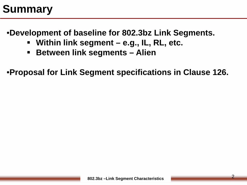
•Development of baseline for 802.3bz Link Segments. Within link segment – e.g., IL, RL, etc. Between link segments – Alien
•Proposal for Link Segment specifications in Clause 126.
Summary
2
802.3bz –Link Segment Characteristics
802.3bz Objectives
3
802.3bz –Link Segment Characteristics
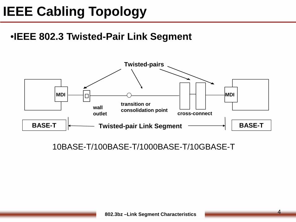
10BASE-T/100BASE-T/1000BASE-T/10GBASE-T
BASE-T
MDI
cross-connectwalloutlet
Twisted-pair Link Segment
Twisted-pairs
MDI
BASE-T
transition or consolidation point
IEEE Cabling Topology
•IEEE 802.3 Twisted-Pair Link Segment
4
802.3bz –Link Segment Characteristics
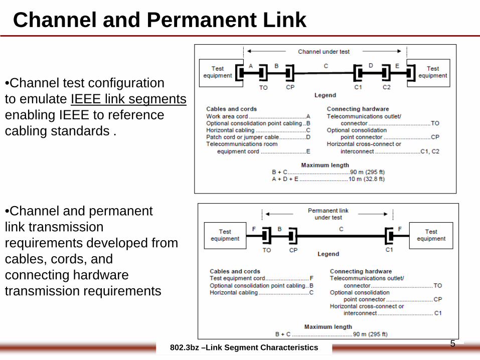
Channel and Permanent Link
•Channel and permanent link transmission requirements developed fromcables, cords, and connecting hardware transmission requirements
•Channel test configurationto emulate IEEE link segmentsenabling IEEE to reference cabling standards .
5
802.3bz –Link Segment Characteristics
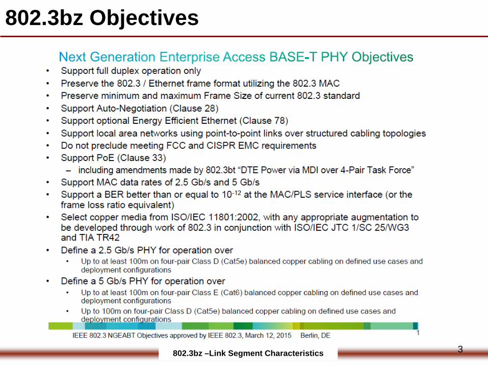
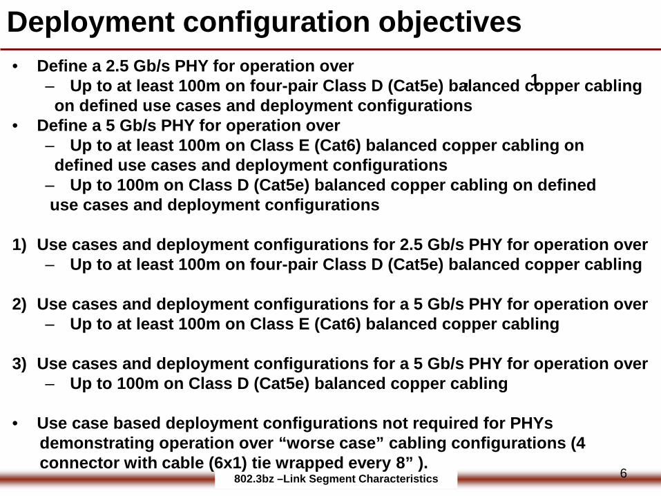
• Define a 2.5 Gb/s PHY for operation over ‒ Up to at least 100m on four-pair Class D (Cat5e) balanced copper cabling on defined use cases and deployment configurations
• Define a 5 Gb/s PHY for operation over‒ Up to at least 100m on Class E (Cat6) balanced copper cabling on defined use cases and deployment configurations ‒ Up to 100m on Class D (Cat5e) balanced copper cabling on defined use cases and deployment configurations
1) Use cases and deployment configurations for 2.5 Gb/s PHY for operation over ‒ Up to at least 100m on four-pair Class D (Cat5e) balanced copper cabling
2) Use cases and deployment configurations for a 5 Gb/s PHY for operation over‒ Up to at least 100m on Class E (Cat6) balanced copper cabling
3) Use cases and deployment configurations for a 5 Gb/s PHY for operation over‒ Up to 100m on Class D (Cat5e) balanced copper cabling
• Use case based deployment configurations not required for PHYs demonstrating operation over “worse case” cabling configurations (4 connector with cable (6x1) tie wrapped every 8” ).
Deployment configuration objectives
, 1
6
802.3bz –Link Segment Characteristics
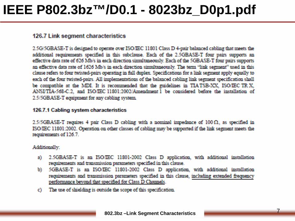
IEEE P802.3bz™/D0.1 - 8023bz_D0p1.pdf
7
802.3bz –Link Segment Characteristics
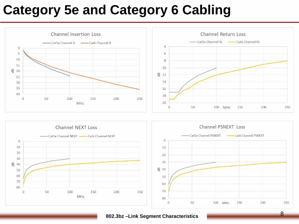
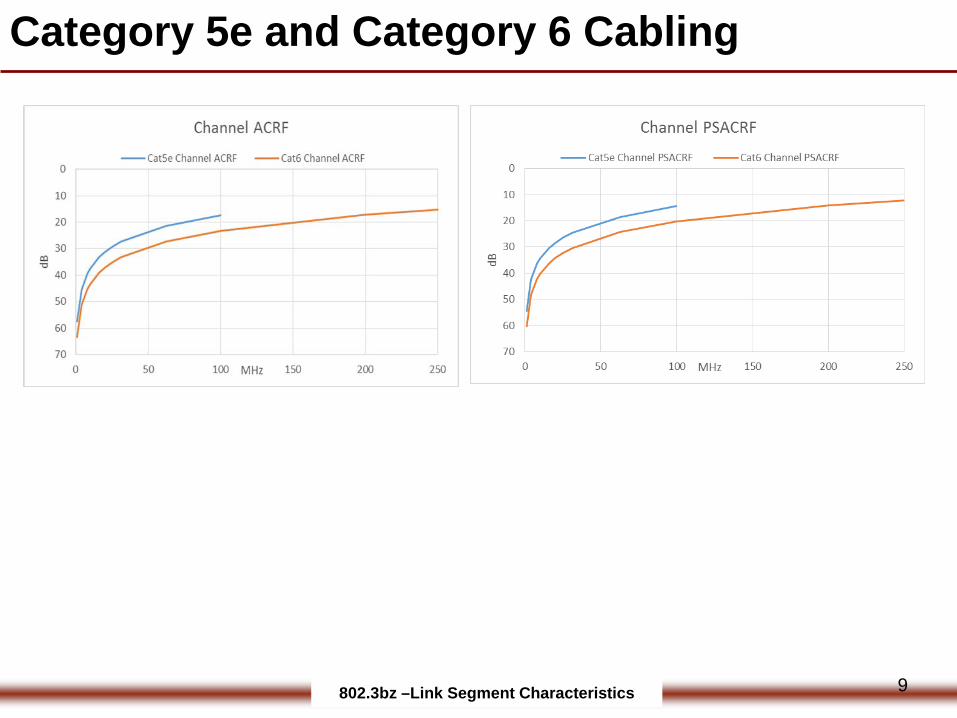
Category 5e and Category 6 Cabling
8
802.3bz –Link Segment Characteristics
Category 5e and Category 6 Cabling
9
802.3bz –Link Segment Characteristics
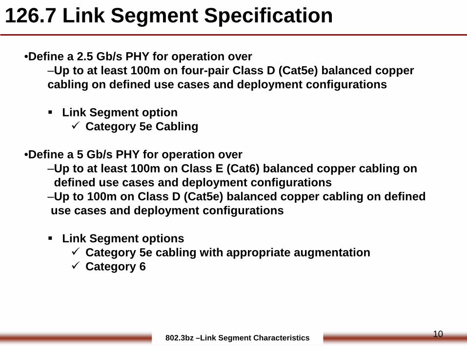
126.7 Link Segment Specification
•Define a 2.5 Gb/s PHY for operation over ‒Up to at least 100m on four-pair Class D (Cat5e) balanced copper cabling on defined use cases and deployment configurations
Link Segment option Category 5e Cabling
•Define a 5 Gb/s PHY for operation over‒Up to at least 100m on Class E (Cat6) balanced copper cabling on defined use cases and deployment configurations ‒Up to 100m on Class D (Cat5e) balanced copper cabling on defined use cases and deployment configurations
Link Segment options Category 5e cabling with appropriate augmentation Category 6
10
802.3bz –Link Segment Characteristics
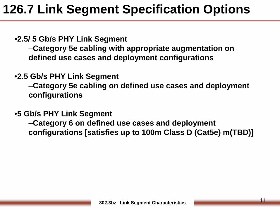
126.7 Link Segment Specification Options
•2.5/ 5 Gb/s PHY Link Segment ‒Category 5e cabling with appropriate augmentation on defined use cases and deployment configurations
•2.5 Gb/s PHY Link Segment ‒Category 5e cabling on defined use cases and deployment configurations
•5 Gb/s PHY Link Segment ‒Category 6 on defined use cases and deployment configurations [satisfies up to 100m Class D (Cat5e) m(TBD)]
11
802.3bz –Link Segment Characteristics
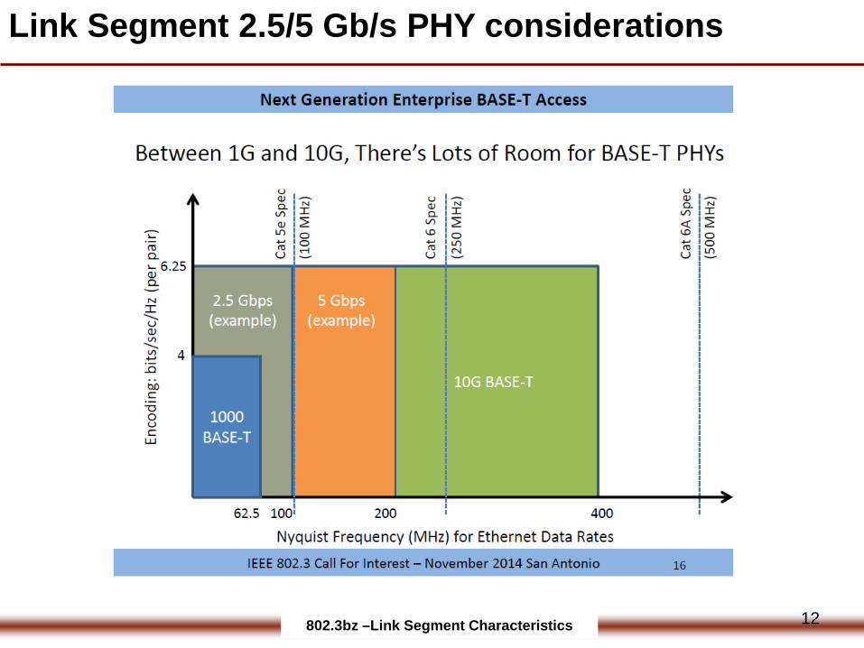
Link Segment 2.5/5 Gb/s PHY considerations
12
802.3bz –Link Segment Characteristics
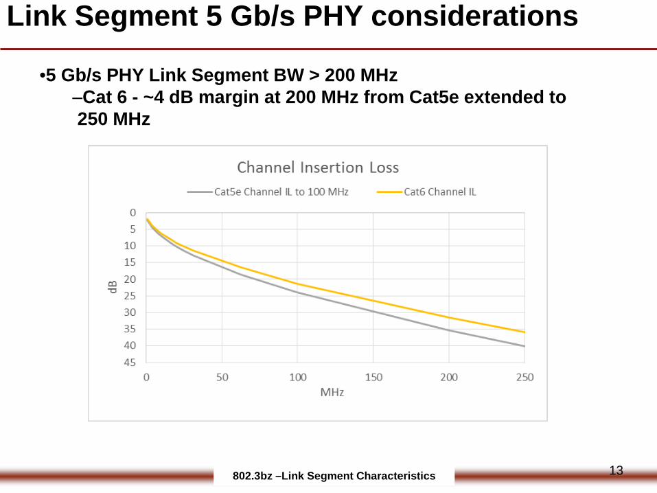
Link Segment 5 Gb/s PHY considerations
•5 Gb/s PHY Link Segment BW > 200 MHz‒Cat 6 - ~4 dB margin at 200 MHz from Cat5e extended to 250 MHz
13
802.3bz –Link Segment Characteristics
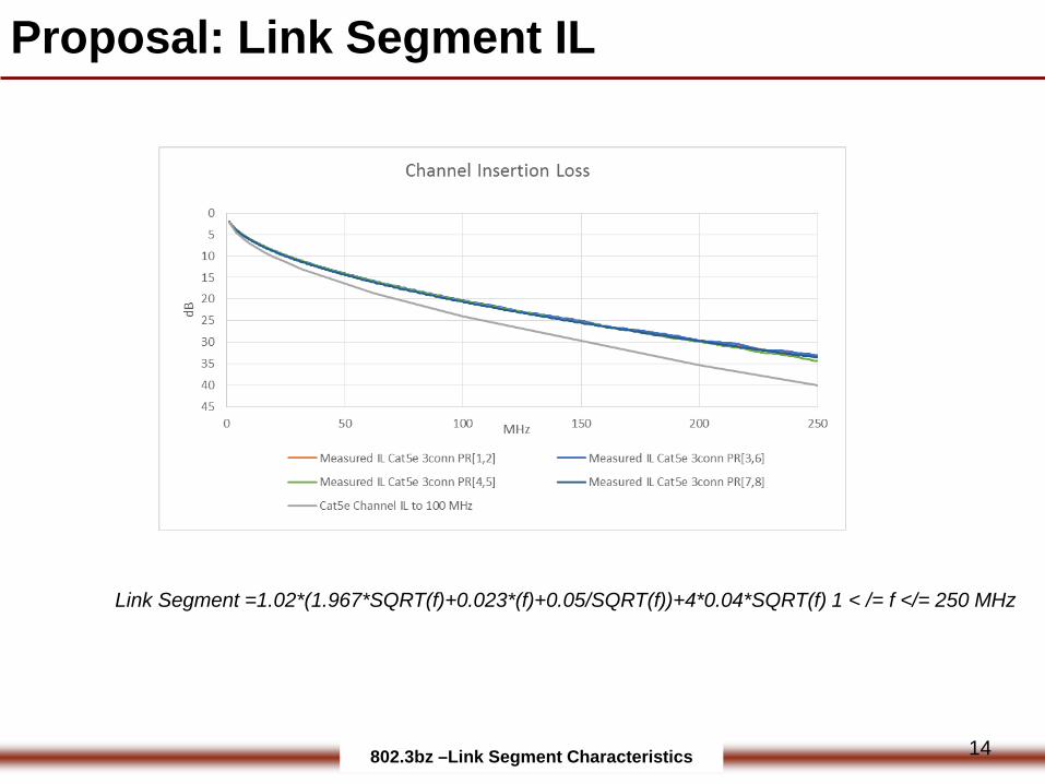
Proposal: Link Segment IL
Link Segment =1.02*(1.967*SQRT(f)+0.023*(f)+0.05/SQRT(f))+4*0.04*SQRT(f) 1 < /= f </= 250 MHz
14
802.3bz –Link Segment Characteristics
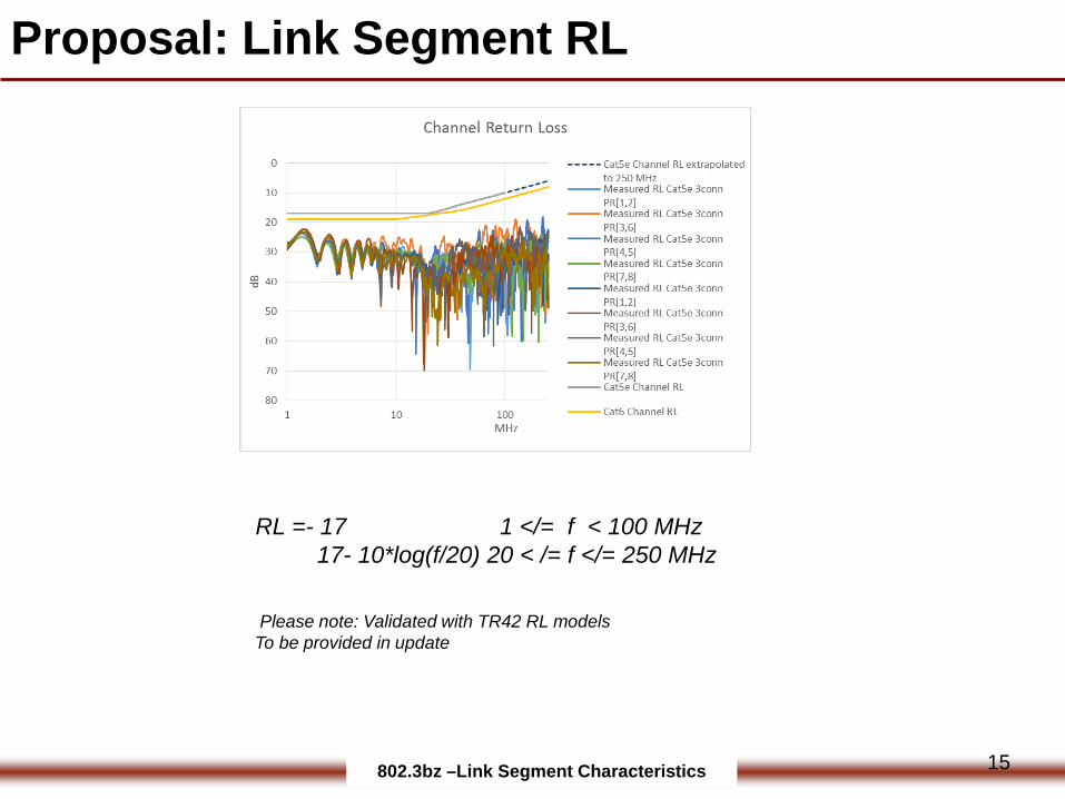
Proposal: Link Segment RL
RL =- 17 1 </= f < 100 MHz17- 10*log(f/20) 20 < /= f </= 250 MHz
Please note: Validated with TR42 RL modelsTo be provided in update
15
802.3bz –Link Segment Characteristics
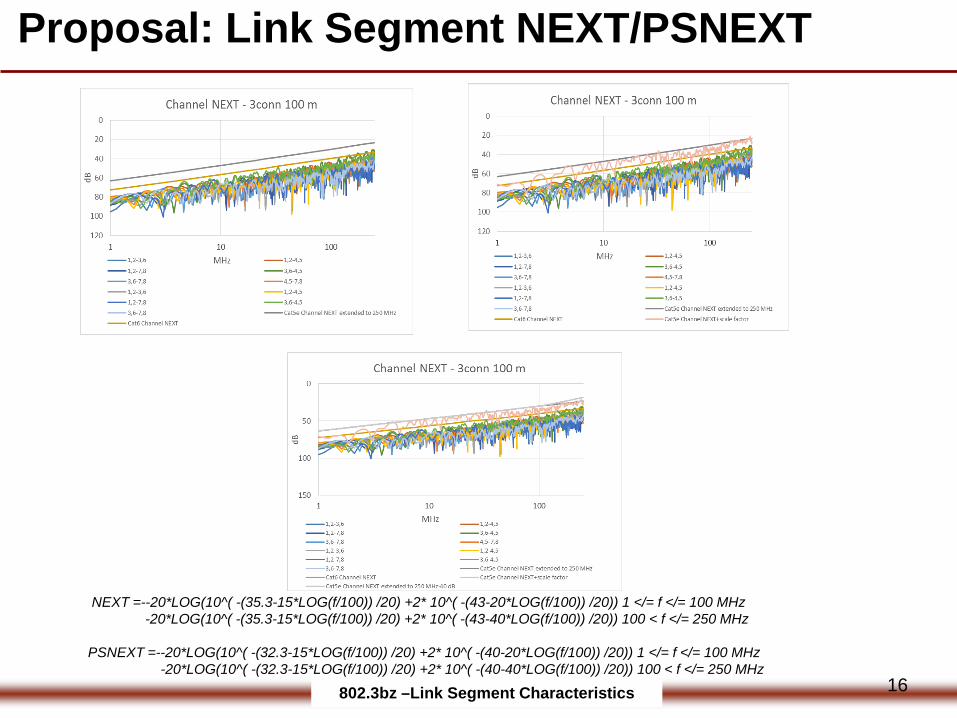
NEXT =--20*LOG(10^( -(35.3-15*LOG(f/100)) /20) +2* 10^( -(43-20*LOG(f/100)) /20)) 1 </= f </= 100 MHz-20*LOG(10^( -(35.3-15*LOG(f/100)) /20) +2* 10^( -(43-40*LOG(f/100)) /20)) 100 < f </= 250 MHz
PSNEXT =--20*LOG(10^( -(32.3-15*LOG(f/100)) /20) +2* 10^( -(40-20*LOG(f/100)) /20)) 1 </= f </= 100 MHz-20*LOG(10^( -(32.3-15*LOG(f/100)) /20) +2* 10^( -(40-40*LOG(f/100)) /20)) 100 < f </= 250 MHz
Proposal: Link Segment NEXT/PSNEXT
16

802.3bz –Link Segment Characteristics
Proposal: Link Segment ACRF/PSACRF
ACRF = -20*LOG( 10^( -(23.8-20*LOG(f/100)) /20) +4* 10^( -(32.1-20*LOG(f/100)) /20)) 1 </= f </= 100 MHzTBD 100 < f </= 250 MHz
PSACRF = -20*LOG( 10^( -(20.8-20*LOG(f/100)) /20) +4* 10^( -(32.1-20*LOG(f/100)) /20)) 1 </= f </= 100 MHzTBD 100 < f </= 250 MHz
17
802.3bz –Link Segment Characteristics
Alien Crosstalk – 10GBASE-T
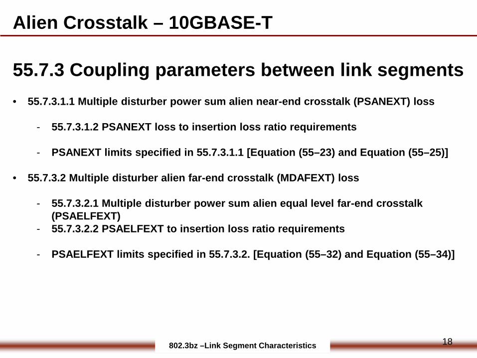
55.7.3 Coupling parameters between link segments• 55.7.3.1.1 Multiple disturber power sum alien near-end crosstalk (PSANEXT) loss
- 55.7.3.1.2 PSANEXT loss to insertion loss ratio requirements
- PSANEXT limits specified in 55.7.3.1.1 [Equation (55–23) and Equation (55–25)]
• 55.7.3.2 Multiple disturber alien far-end crosstalk (MDAFEXT) loss
- 55.7.3.2.1 Multiple disturber power sum alien equal level far-end crosstalk (PSAELFEXT)
- 55.7.3.2.2 PSAELFEXT to insertion loss ratio requirements
- PSAELFEXT limits specified in 55.7.3.2. [Equation (55–32) and Equation (55–34)]
18

802.3bz –Link Segment Characteristics
Alien Crosstalk – 10GBASE-T
• 55.7.3.3 Alien crosstalk margin computation
The alien crosstalk margin computation can be applied in the event that the PSANEXT limits specified in 55.7.3.1.1 [Equation (55–23) and Equation (55–25)] or the PSAELFEXT limits specified in 55.7.3.2. [Equation (55–32) and Equation (55–34)] are not met. The alien crosstalk margin is specified for each of the individual 4-pairs as well as the average “across the 4-pairs”.
19
802.3bz –Link Segment Characteristics
Proposal: Alien Crosstalk
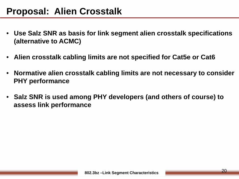
• Use Salz SNR as basis for link segment alien crosstalk specifications (alternative to ACMC)
• Alien crosstalk cabling limits are not specified for Cat5e or Cat6
• Normative alien crosstalk cabling limits are not necessary to consider PHY performance
• Salz SNR is used among PHY developers (and others of course) to assess link performance
20