8-horse panel walker - priefert horse walkers horse panel walker assembly...side of the horse walker...
TRANSCRIPT
www.priefert.com 800-527-8616
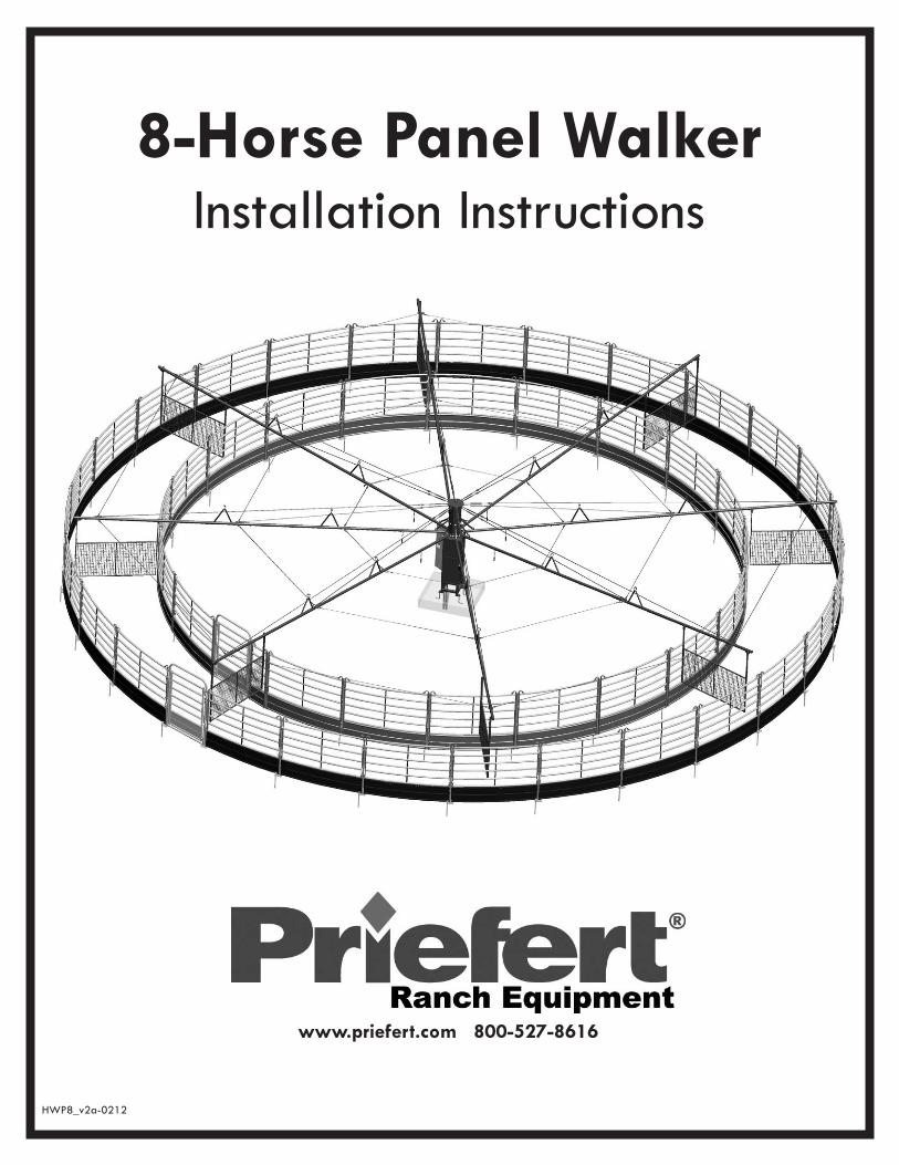
8-Horse Panel Walker Installation Instructions
HWP8_v2a-0212
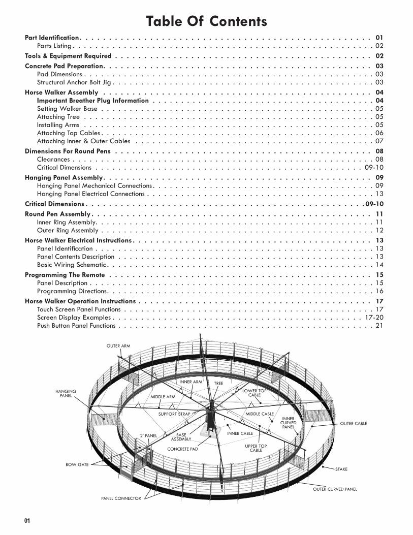
Table Of ContentsPart Identification . . . . . . . . . . . . . . . . . . . . . . . . . . . . . . . . . . . . . . . . . . . . . . . . . . 01
Parts Listing . . . . . . . . . . . . . . . . . . . . . . . . . . . . . . . . . . . . . . . . . . . . . . . . . . . . . 02Tools & Equipment Required . . . . . . . . . . . . . . . . . . . . . . . . . . . . . . . . . . . . . . . . . . . . 02Concrete Pad Preparation. . . . . . . . . . . . . . . . . . . . . . . . . . . . . . . . . . . . . . . . . . . . . . 03
Pad Dimensions . . . . . . . . . . . . . . . . . . . . . . . . . . . . . . . . . . . . . . . . . . . . . . . . . . . 03Structural Anchor Bolt Jig . . . . . . . . . . . . . . . . . . . . . . . . . . . . . . . . . . . . . . . . . . . . . . 03
Horse Walker Assembly . . . . . . . . . . . . . . . . . . . . . . . . . . . . . . . . . . . . . . . . . . . . . . 04Important Breather Plug Information . . . . . . . . . . . . . . . . . . . . . . . . . . . . . . . . . . . . . . . 04Setting Walker Base . . . . . . . . . . . . . . . . . . . . . . . . . . . . . . . . . . . . . . . . . . . . . . . . 05Attaching Tree . . . . . . . . . . . . . . . . . . . . . . . . . . . . . . . . . . . . . . . . . . . . . . . . . . . 05Installing Arms . . . . . . . . . . . . . . . . . . . . . . . . . . . . . . . . . . . . . . . . . . . . . . . . . . . 05Attaching Top Cables . . . . . . . . . . . . . . . . . . . . . . . . . . . . . . . . . . . . . . . . . . . . . . . . 06Attaching Inner & Outer Cables . . . . . . . . . . . . . . . . . . . . . . . . . . . . . . . . . . . . . . . . . . 07
Dimensions For Round Pens . . . . . . . . . . . . . . . . . . . . . . . . . . . . . . . . . . . . . . . . . . . . 08Clearances . . . . . . . . . . . . . . . . . . . . . . . . . . . . . . . . . . . . . . . . . . . . . . . . . . . . . 08Critical Dimensions . . . . . . . . . . . . . . . . . . . . . . . . . . . . . . . . . . . . . . . . . . . . . . . 09-10
Hanging Panel Assembly. . . . . . . . . . . . . . . . . . . . . . . . . . . . . . . . . . . . . . . . . . . . . . 09Hanging Panel Mechanical Connections . . . . . . . . . . . . . . . . . . . . . . . . . . . . . . . . . . . . . . . 09Hanging Panel Electrical Connections . . . . . . . . . . . . . . . . . . . . . . . . . . . . . . . . . . . . . . . . 13
Critical Dimensions . . . . . . . . . . . . . . . . . . . . . . . . . . . . . . . . . . . . . . . . . . . . . . . . 09-10Round Pen Assembly . . . . . . . . . . . . . . . . . . . . . . . . . . . . . . . . . . . . . . . . . . . . . . . . 11
Inner Ring Assembly . . . . . . . . . . . . . . . . . . . . . . . . . . . . . . . . . . . . . . . . . . . . . . . . . 11Outer Ring Assembly . . . . . . . . . . . . . . . . . . . . . . . . . . . . . . . . . . . . . . . . . . . . . . . . 12
Horse Walker Electrical Instructions . . . . . . . . . . . . . . . . . . . . . . . . . . . . . . . . . . . . . . . . . 13Panel Identification . . . . . . . . . . . . . . . . . . . . . . . . . . . . . . . . . . . . . . . . . . . . . . . . . 13Panel Contents Description . . . . . . . . . . . . . . . . . . . . . . . . . . . . . . . . . . . . . . . . . . . . . 13Basic Wiring Schematic . . . . . . . . . . . . . . . . . . . . . . . . . . . . . . . . . . . . . . . . . . . . . . . 14
Programming The Remote . . . . . . . . . . . . . . . . . . . . . . . . . . . . . . . . . . . . . . . . . . . . . 15Panel Description . . . . . . . . . . . . . . . . . . . . . . . . . . . . . . . . . . . . . . . . . . . . . . . . . . 15Programming Directions . . . . . . . . . . . . . . . . . . . . . . . . . . . . . . . . . . . . . . . . . . . . . . . 16
Horse Walker Operation Instructions . . . . . . . . . . . . . . . . . . . . . . . . . . . . . . . . . . . . . . . . 17Touch Screen Panel Functions . . . . . . . . . . . . . . . . . . . . . . . . . . . . . . . . . . . . . . . . . . . . 17Screen Display Examples . . . . . . . . . . . . . . . . . . . . . . . . . . . . . . . . . . . . . . . . . . . . 17-20 Push Button Panel Functions . . . . . . . . . . . . . . . . . . . . . . . . . . . . . . . . . . . . . . . . . . . . . 21
SUPPORT STRAP
INNER ARM
MIDDLE ARM
OUTER ARM
LOWER TOPCABLE
UPPER TOPCABLE
BOW GATE
PANEL CONNECTOR
2' PANEL
OUTER CURVED PANEL
INNERCURVED PANEL
STAKE
HANGINGPANEL
OUTER CABLE
CONCRETE PAD
BASE ASSEMBLY
TREE
INNER CABLE
MIDDLE CABLE
01

⅜" Quick Links (48 ea) FM06QL
Tools & Equipment Required
Stabilizer Bar (8 ea) HWPSBWE
Hanging Panel (8 ea) HWPWE
02
Tree (1 ea) HW8TREE
Inner Panel (20 ea) HW8CPI
Outer Panel (27 ea) HW8CPO
2' Panel (1 ea) HWRPP02
5' Bow Gate (2 ea) HWRPBG05
Post Connector (50 ea) HWRPP-N
⅝" Shackle (16 ea) C10AS
Anchor Stake (50 ea) RBSTAKE
Lower Top Cables ½" X 2053/4" (8 ea)
HW8.500x205.75
Middle Turnbuckle Cables 5/16" X 1547/16" (2 ea)
HW8.312x154.4375
Inner Turnbuckle Cable 5/16" X 66" (2 ea)
HW8.312x066
Base Assembly
(1 ea)HWBASE
Inner Cables 5/16" x 85¼" (6 ea)
HW8.312x085.125
Middle Cables 5/16" X 1777/8" (6 ea)
HW8.312x177.875
Outer Turnbuckle Cables 5/16" X 2785/8" (2 ea)
HW8.312x278.0625
Outer Cables 5/16" X 2975/8" (6 ea)
HW8.312x297.625
Support Strap (8 ea) HWPARMSTRAP
Upper Top Cable ½" X 3641/8" (8 ea)
HW8.500x364.125
⅝" Turnbuckle (16 ea) FMTB1012
½" Turnbuckle (6 ea) FMTB0812
Panel Strap - Long (8 ea) HWPARML
Panel Strap - Short (8 ea) HWPARMS
Forklift or Front End Loader
Outer Arm (8 ea) HW6OUTERARM
Middle Arm (8 ea) HW8MIDDLEARM
Inner Arm (8 ea) HWINNERARM
Parts List
Shovel & possibly a pickaxe
Sledgehammer
LevelTapeMeasure
Adjustable Wrench
Wire Strippers
Pliers
Impact fitted with 3/4”, 15/16”, & 7/16”sockets
Ladder
Chain or Heavy-Duty Tie-Down Strap
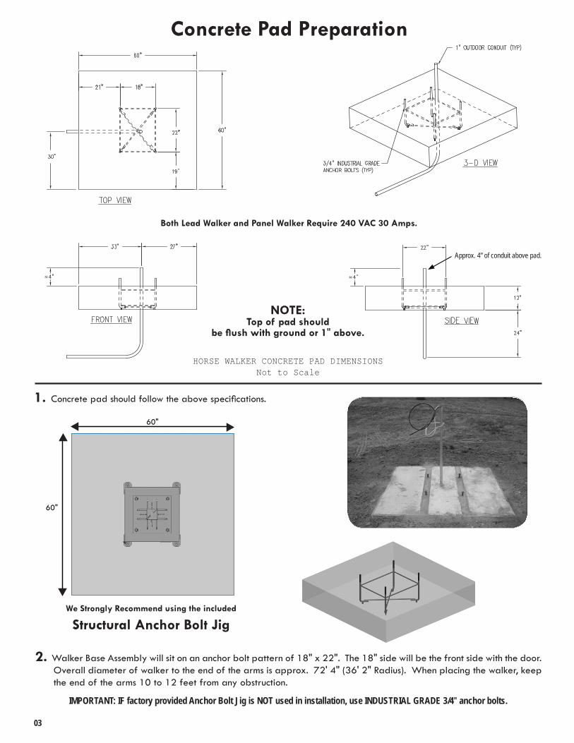
1. Concrete pad should follow the above specifications.
2. Walker Base Assembly will sit on an anchor bolt pattern of 18" x 22" . The 18" side will be the front side with the door . Overall diameter of walker to the end of the arms is approx . 72' 4" (36' 2" Radius) . When placing the walker, keep the end of the arms 10 to 12 feet from any obstruction .
03
IMPORTANT: IF factory provided Anchor Bolt Jig is NOT used in installation, use INDUSTRIAL GRADE 3/4" anchor bolts.
NOTE:Top of pad should
be flush with ground or 1" above.
60"
60"
We Strongly Recommend using the included
Structural Anchor Bolt Jig
Concrete Pad Preparation
Both Lead Walker and Panel Walker Require 240 VAC 30 Amps.
Approx. 4” of conduit above pad.
HORSE WALKER CONCRETE PAD DIMENSIONSNot to Scale
04
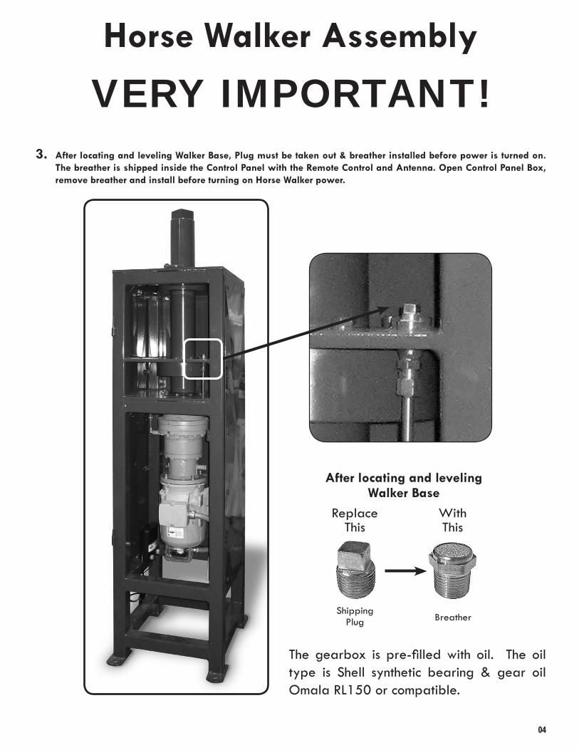
VERY IMPORTANT!Horse Walker Assembly
3. After locating and leveling Walker Base, Plug must be taken out & breather installed before power is turned on. The breather is shipped inside the Control Panel with the Remote Control and Antenna. Open Control Panel Box, remove breather and install before turning on Horse Walker power.
The gearbox is pre-filled with oil. The oil type is Shell synthetic bearing & gear oil Omala RL150 or compatible .
Replace This
WithThis
Shipping Plug Breather
After locating and leveling Walker Base
05
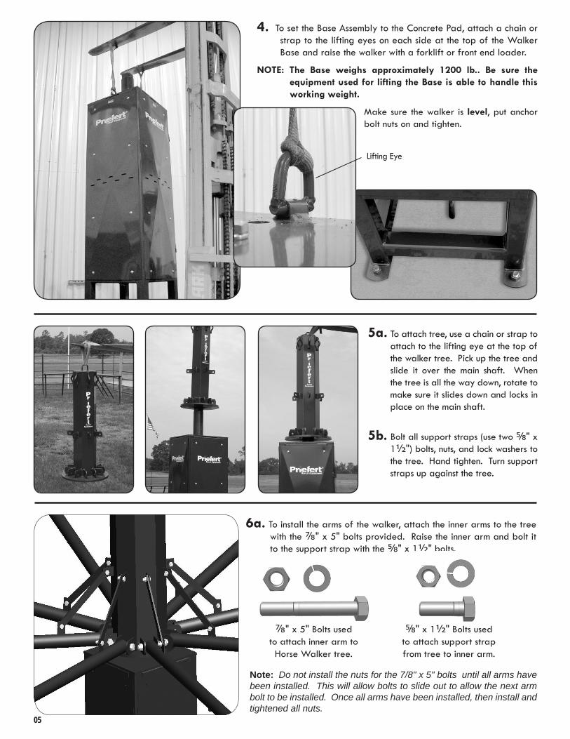
6a. To install the arms of the walker, attach the inner arms to the tree with the ⅞" x 5" bolts provided . Raise the inner arm and bolt it to the support strap with the ⅝" x 1½" bolts .
⅞" x 5" Bolts used to attach inner arm to Horse Walker tree .
⅝" x 1½" Bolts used to attach support strap from tree to inner arm .
Note: Do not install the nuts for the 7/8" x 5" bolts until all arms have been installed. This will allow bolts to slide out to allow the next arm bolt to be installed. Once all arms have been installed, then install and tightened all nuts.
5a. To attach tree, use a chain or strap to attach to the lifting eye at the top of the walker tree . Pick up the tree and slide it over the main shaft . When the tree is all the way down, rotate to make sure it slides down and locks in place on the main shaft .
5b. Bolt all support straps (use two ⅝" x 1½") bolts, nuts, and lock washers to the tree . Hand tighten . Turn support straps up against the tree .
4. To set the Base Assembly to the Concrete Pad, attach a chain or strap to the lifting eyes on each side at the top of the Walker Base and raise the walker with a forklift or front end loader .
NOTE: The Base weighs approximately 1200 lb.. Be sure the equipment used for lifting the Base is able to handle this working weight.
Make sure the walker is level, put anchor bolt nuts on and tighten .
Lifting Eye

8a. Attach the 2053/4" (½") lower top cables to the middle arm . To do this, attach the ⅝" shackle to the cable eye and the top loop at the end of the middle arm . Then, bolt one end of the ⅝” turnbuckle to the other end of the cable . Bolt the other end of the turnbuckle to the bottom hole on plate at the top of the tree .
NOTE: This will require someone, or a lifting device, to raise the outer end of the arm to allow enough slack to bolt the turnbuckle to the tree . The turnbuckles need to be unscrewed all of the way out until there is a full thread left in the nuts .
06
8b. Continue to attach lower top cables until all eight arms are complete . Gently snug all of the lower top cables . Do Not fully tighten lower top cables before attaching upper top cables .
6b. Repeat to attach all eight inner arms to the tree .
7. Slide the end of the middle arm over the end of the inner arm until the two pieces butt together . Slide the outer arm over the end of the middle arm until those two pieces butt together .
9. Repeat the previous procedure to attach the 3641/8" (½") upper top cables to the outer arm . Again, this will require someone, or a lifting device, to raise the outer end of the arm to allow enough slack to bolt the turnbuckle to the top hole on plate at the top of the tree . Continue to attach upper top cables until all eight arms are complete . Tighten all of the top cables until there is a slight bow in the arm . Check to be sure the cables are tightened uniformly without excessive tension on lower or upper top cables .
*4 Horse Walker shown
⅝" Shackle
Cable Eye
Bottom Hole
Top Hole

10a. Attach the six 85¼" (5/16") inner cables, half on either side, to the loops at the center of the inner arms by using the ⅜” Quick Links provided .
10b. Using the previous procedure, attach the six 177⅞” (5/16”) middle cables in the same manner as the inner cables . Attach at the centers of the arms by using the Quick Links to attach the cable ends to the loops on the side of the arm .
10c. Repeat procedure once again for the outer cables . Attach the six 297⅝” (5/16”) outer cables in the same manner as the inner cables . Attach at the ends of the arms using the quick links to attach the cable ends to the loops on the side of the arm .
11a. Attach one of the two 66" (5/16") inner cables at one end with Quick Link and the ½” turnbuckle at the other end . Attach the other on the opposite side of the walker, in the same location . Gently snug the turnbuckles until the slack is out of all eight inner cables .
11b. As before, attach one of the two 1547/16” (5/16”) middle cables at one end with quick link and the ½” turnbuckle at the other end . Attach the other on the opposite side of the walker, in the same location . Position the turnbuckle opposite to the turnbuckle of the inner cables . Gently snug the turnbuckle until the slack is out of all eight center cables .
11c. As before, attach one of the two 278⅝” (5/16”) outer cables at one end with Quick Link and the ½” turnbuckle at the other end . Attach the other on the opposite side of the walker, in the same location . Position the turnbuckle opposite to the turnbuckle of the center cables . Gently snug the turnbuckle until the slack is out of all eight outer cables .
07
3/8” Quick Link
NOTE: DO NOT TIGHTEN ANY INNER, MIDDLE OR OUTTER TURNBUCKLES UNTIL ALL CABLES ARE ATTACHED!
NOTE: WHEN TIGHTENING CABLES, BE SURE TO TIGHTEN TURNBUCKLES UNIFORMLY TO PREVENT WARPING
OR BOWING OF THE ARMS .
FIRST, Install side cables, one side of the Walker at a time. THEN, install the Turnbuckle cables to pull the two sides together evenly to prevent the arms from bowing. Turnbuckle cables should be installed last.Overtightening will cause the arms to bow.
Install These TurnbucklesCables Last
Install These TurnbucklesCables Last
Install TheseSide Cables
First
Install TheseSide Cables
First
12. Tighten all the turnbuckles progressively until all of the slack is out of all 24 cables, taking up slack uniformly . This will prevent uneven arm alignment . After all of the cables are in place, the top turnbuckles may need to be tightened again .
Install All Side Cables
First
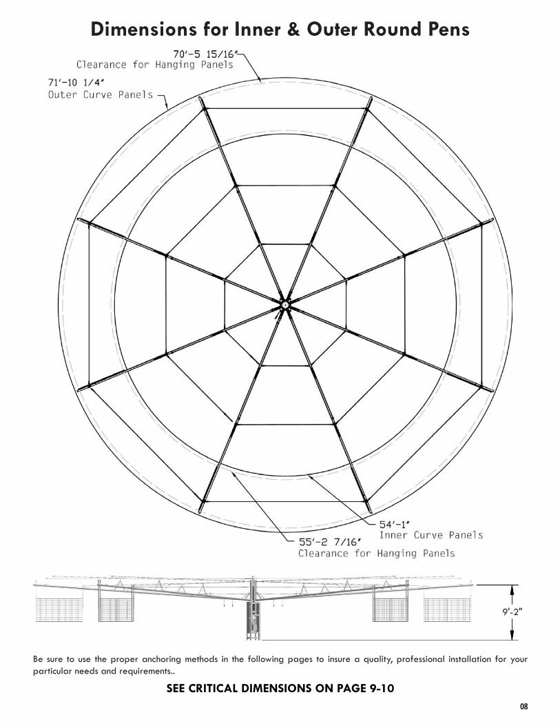
Dimensions for Inner & Outer Round Pens
Be sure to use the proper anchoring methods in the following pages to insure a quality, professional installation for your particular needs and requirements . .
SEE CRITICAL DIMENSIONS ON PAGE 9-1008
9'-2"

Hanging Panel Assembly
1. Bolt the Panel Mounting Bracket & Arm Attachments to the Horse Walker . Please note that the Long Arm Attachment attaches to the outer ear of the horse walker arm, and the Short Arm Attachment attaches to the inner ear . (See example pg . 10)
NOTE: Do NOT overtighten . Allow straps to pivot from bracket .
2. Make sure the panels are hanging level . (See detail at bottom of pg . 09-10) . Height and Cable adjustments may be made by selecting different hole settings . The “warning” decal on the long hanging strap will go to the outside of the walker (See inset pg . 10) .
Panel MountingBracket
3. Run the panel charger wire along the arm securing it to the arm with the tie wraps provided . The wire should be connected to the nylatron ring located on the bottom side of the Horse Walker tree . The wire should be attached to the panel by crimping the wire loops provided, and attached to the nylatron ring by using the ¼" x ½" bolts . See Page 13 for Electrical Connections.
09
Allow 14' minimum height clearance from Concrete Base to any overhead structure to provide space to assemble or remove
Tree from Base assembly .
NOTE:Be sure to allow ample
clearance overhead if an overhead cover is to be used .
14’ minimum clearance is required .
Approximately 10' overall height
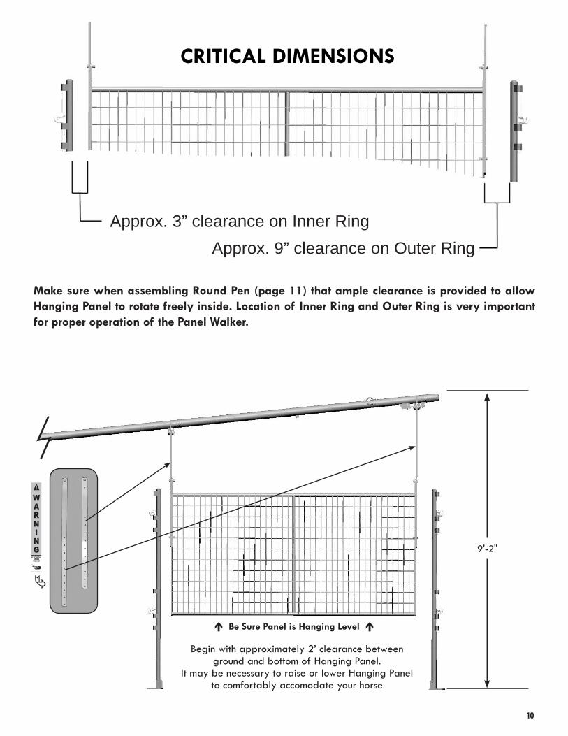
CRITICAL DIMENSIONS
10
Make sure when assembling Round Pen (page 11) that ample clearance is provided to allow Hanging Panel to rotate freely inside. Location of Inner Ring and Outer Ring is very important for proper operation of the Panel Walker.
9'-2"
Approx. 3” clearance on Inner RingApprox. 9” clearance on Outer Ring
Be Sure Panel is Hanging Level
Begin with approximately 2’ clearance between ground and bottom of Hanging Panel .
It may be necessary to raise or lower Hanging Panel to comfortably accomodate your horse

2. Locate the 2' Panel . Attach the panel on the Post Connector with connector pins as shown in DETAIL A . Place another Post Connector on the other side of the panel and attach as before . Slide all connector pins on the Post Connectors up and into clips extruding from the panel .
3. As you are installing the panels, manually turn the Horse Walker Hanging panel that is attached to the arm, rotating around to each panel to make sure you have the proper clearance . After clearance is achieved, drive (1) Anchor Stake, through hole on Post Connector half-way into ground as you work your way around . Take an Inner Ring Panel and slide onto the corresponding Panel Connector clips as shown in DETAIL A . Add another Panel Connector on the other end of the panel . Continue around Inner Ring to meet first Panel Connector on Bow Gate.
A
Round Pen AssemblyBefore Beginning:Rotate the Horse Walker Tree around until there is a hanging panel in-line with the first Post Connector. As you install the curve panels and gate, move the Round Pen panels around until there is approx . 3" of clearance between the hanging panel and Post Connector on the Inner Ring and approx . 7" on Outer Ring, as shown on page 9-10 under Critical Dimensions (you may have to remove previously driven stakes for adjustments). After the first Post Connector is in place, (re)drive (1) Stake halfway into the ground, going through the Anchor Holes of the Post Connector . Repeat as you work your way around with Curved Panels and Panel Connectors until you work all the way around to the first Post connector.
NOTE: Do not drive stakes completely into the ground until all panels are assembled and located to allow for adjustment if needed.
Inner Ring - First
1. Locate position for the 5' Bow Gate . Attach the Bow Gate to the Post Connector using the connector pins on the Post Connector and the clips extruding from the Bow Gate as shown in DETAIL A . Place another Post Connector on the other side of Bow Gate with connector pins attached to Bow Gate. Be sure the holes on the anchoring flange face inward toward the walker Base in the center of the ring .
11
Post Connector
Anchor holes of Post Connector Anchor
Stake

Outer Ring - Second
4. Following the procedure used for the Inner Ring, locate the Bow Gate for the Outer Ring, directly across from the Inner Bow Gate . Connect an Outer Panel as in step 1 . Attach the Panel as before . Place another Panel and continue around Outer Ring. Be sure the holes on the anchoring flange face outward, away from the center of the ring.
12
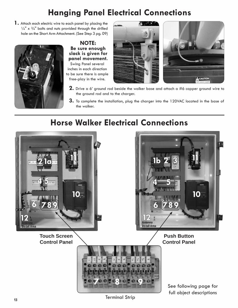
1. Attach each electric wire to each panel by placing the ¼" x ¾" bolts and nuts provided through the drilled hole on the Short Arm Attachment . (See Step 3 pg . 09)
NOTE: Be sure enough
slack is given for panel movement. Swing Panel several
inches in each direction to be sure there is ample
free-play in the wire .
2. Drive a 6’ ground rod beside the walker base and attach a #6 copper ground wire to the ground rod and to the charger .
3. To complete the installation, plug the charger into the 120VAC located in the base of the walker .
13
Horse Walker Electrical Connections
8
4 5
610
11
Antenna Install Area
12789
Touch ScreenControl Panel
1a2 3
4 5
610
11
Antenna Install Area
12789
Push ButtonControl Panel
1b 2
Terminal Strip
7 8 9 See following page for full object descriptions
Hanging Panel Electrical Connections

A certified electrician must install wiring and wire motor control.
Horse Walker Electrical Instructions (cont.)
1a . Power Supply (Touch Screen Control Panel Only)
1b . PLC - Program Logic Controller (Push Button Control Panel Only)
2 . Main Power Contactor3 . 110VAC Power Supply
(Push Button Control Panel Only)
4 . Fuse Block with 10 Amp Fuse5 . Control Terminal Blocks6 . Receiver7 . Main Power Terminal Strip
Main Power Requirements: 240 volt AC 30 AmpsUse minimum of #10 gauge wire; from breaker box (Use Electrical Code for distance of circuit run & wire size)Run main service to enclosure in electrical conduit 1" minimum .Connect wires from 30 Amp double pole breaker to L1 and L2 on main power terminal strip .Connect white wire from neutral bar in breaker box to N on Main power terminal strip . Connect green ground wire from ground bar in breaker box to G on main power terminal strip .
8 . Fence Charger Terminal Strip (Panel Walker Only)Output Power for Charger120VAC for Charger Receptacle
9 . Motor Terminal StripMotor Power Requirements: Use #10 gauge wire black, red, blue, & green Run 1" electrical conduit from the enclosure to the motor junction box .Connect the black wire to T1 on motor terminal strip to the black wire in the motor junction box .Connect the red wire to T2 on motor terminal strip to the red wire in the motor junction box .Connect the blue wire to T3 on motor terminal strip to the blue wire in the motor junction box . Connect the green ground wire to G on motor terminal strip to the green ground wire in the motor junction box .
10 . Panel Walker ONLYFence Charger Requirements:Black, white, and green #12 wires must be run from the control box to the walker base junction box .(It is acceptable to run these wires in the same conduit as the motor power wires .) At the junction box, connect these wires to the #12 black, white, and green wires which are terminated at the 120VAC plug in the walker base . At the control box, terminate the #12 wires to the terminal blocks shown .Black - L1 White - N Green - G
11 . Line Reactor12 . Antenna Install Area
CONTROL PANEL
14
POWERSUPPLY
CONTROLBOX
WALKERJUNCTION
BOXat Base
L1 - BlackL1 - BlackN - WhiteG - GreenT1 - BlackT2 - RedT3 - BlueG - Green
L2 - Red
N - White
G - Green
4 WiresSee Item 7
7 WiresSee Items 9 & 10
Basic Wiring Schematic
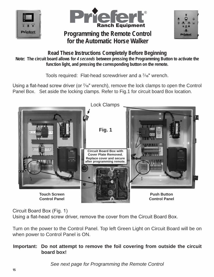
Programming the Remote Control for the Automatic Horse Walker
Read These Instructions Completely Before Beginning Note: The circuit board allows for 4 seconds between pressing the Programming Button to activate the
function light, and pressing the corresponding button on the remote.
Tools required: Flat-head screwdriver and a 7/16" wrench.
Using a flat-head screw driver (or 7/16" wrench), remove the lock clamps to open the Control Panel Box. Set aside the locking clamps. Refer to Fig.1 for circuit board Box location.
Circuit Board Box (Fig. 1)Using a flat-head screw driver, remove the cover from the Circuit Board Box.
Turn on the power to the Control Panel. Top left Green Light on Circuit Board will be on when power to Control Panel is ON.
Important: Do not attempt to remove the foil covering from outside the circuit board box!
See next page for Programming the Remote Control
Touch ScreenControl Panel
Push ButtonControl Panel
Fig. 1
Lock Clamps
15
Circuit Board Box with Cover Plate Removed.
Replace cover and secure after programming remote.

REMEMBER: The circuit board allows for 4 seconds between pressing the Red Programming Button to activate the LED function light, and pressing the corresponding button on the remote.
Press Red Programming Button
This Function Light
will appear(Red LED)
Then Press this button on
the Remote
1Press and hold the red Programming Button until the 1st function light (Red LED) comes on. Immediately press the “O/1” button on the Remote. — the red LED light will blink.
This Function Light
will appear(Red LED)
Then Press this button on
the Remote
Press the red Programming Button again,the 2nd function light (Red LED) will appear. Immediately press the “Faster” button on the Remote. —the red LED light will blink.
Press Red Programming Button2
This Function Light
will appear(Red LED)
Then Press this button on
the Remote
Press the red Programming Button again, the 3rd function light (Red LED) will appear. Immediately press the “Slower” button on the Remote. — the red LED light will blink.
Press Red Programming Button3
This Function Light
will appear(Green LED)
Then Press this button on
the Remote
Press the red Programming Button again, the 4th function light (Green LED) will appear. Immediately press the “Fwd/Rev” button on the Remote. — the green LED light will blink.
Press Red Programming Button4
Your Remote is now programmed to operate. Wait for the four function lights to shut off before powering off the Control Box.
Replace the cover on the Circuit Board Box and close the Control Panel Box. You may now begin using your Priefert Horse Walker.16

Horse Walker Operation Instructions
Charger ON/OFFStops Horse Walker
Charger Indicator
Touch Keys
Display Panel
TOUCH SCREEN CONTROL PANEL
Key Features on the Touch Screen Control Panel:
• 25 second “ramp up” time from start to the desired speed setting helps ease horse into a walk .
• 35 second “ramp down” time from engage to full stop .• Remote control that allows the operator to Start/Stop,
change direction (Forward/Reverse), as well as increase or decrease speed; all with a push of a button .
• Convenient switch to allow low impedance electrical stimulus to drop panels, encouraging horses to keep pace, which can be turned off as horses become accustomed to routines .
• Customized programming for up to 20 automated exercise routines . Each routine can be programmed with up to 12 steps for changing pace, direction, etc .
• Flexibility to choose Programmed Routines or use the Manual option .
The Start-up menu will be the first screen that comes up after powering up the control panel.
Pressing the “Manual” block accesses the manual operating screen .
The “Routine” block changes to the routine run screen .
The “Ratio” Block is “Password protected”; the operator should never need to access this screen .
Note: After 5 minutes, the backlight for the display screen will go into auto-save mode to prolong backlight life . We recommend that you press the square or arrow blocks on the left to illuminate display the screen while the walker is operating . This will reduce the chances of inadvertently changing the current settings .
17
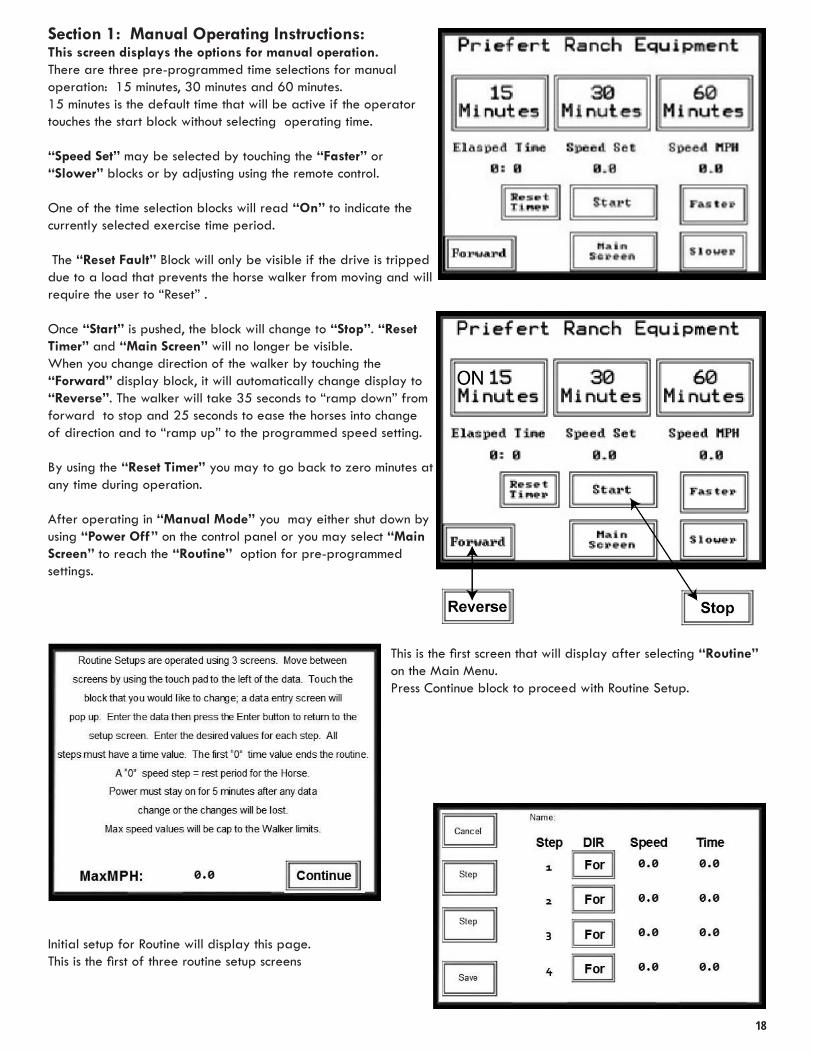
Section 1: Manual Operating Instructions:This screen displays the options for manual operation. There are three pre-programmed time selections for manual operation: 15 minutes, 30 minutes and 60 minutes . 15 minutes is the default time that will be active if the operator touches the start block without selecting operating time .
“Speed Set” may be selected by touching the “Faster” or “Slower” blocks or by adjusting using the remote control .
One of the time selection blocks will read “On” to indicate the currently selected exercise time period .
The “Reset Fault” Block will only be visible if the drive is tripped due to a load that prevents the horse walker from moving and will require the user to “Reset” .
Once “Start” is pushed, the block will change to “Stop” . “Reset Timer” and “Main Screen” will no longer be visible .When you change direction of the walker by touching the “Forward” display block, it will automatically change display to “Reverse” . The walker will take 35 seconds to “ramp down” from forward to stop and 25 seconds to ease the horses into change of direction and to “ramp up” to the programmed speed setting .
By using the “Reset Timer” you may to go back to zero minutes at any time during operation .
After operating in “Manual Mode” you may either shut down by using “Power Off” on the control panel or you may select “Main Screen” to reach the “Routine” option for pre-programmed settings .
This is the first screen that will display after selecting “Routine” on the Main Menu . Press Continue block to proceed with Routine Setup .
Initial setup for Routine will display this page . This is the first of three routine setup screens
18

Section 2 - Programming Routine SettingsTo Create a Name for a Routine:Default Name is always Routine# (example Rt1, Rt2…)
1. Touch to the right of “Name” (Fig . 2-3) to create a name for the first routine.
2. A display will appear with an alphabetic keyboard with Lock, Shift and Space functions .
• Pressing the lock key will switch the display from lower case to all upper case alpha keys and pressing lock again will default to displaying lower case .
• Pressing the Shift key down will only Capitalize the first letter that is chosen and will default back to lower case on the display for the next key entry .
• Pressing the Symbol key will switch screens from Alpha to Numerical including Symbols .
• To capitalize press the Shift key (display will change to show uppercase letters) . Press shift key to toggle back to lower case . Or you may press on Lock to lock upper case choices while programming
• There is a symbol key that will toggle the key board to display numeric and symbols that you may also include-within any given name . Name may include alphanumeric or symbol keystrokes and is limited to 20 characters .
3. Type in desired name and touch “Save” and then “Exit” .
Programming Direction Speed and TimeThe display screen allows you to program Steps 1-4
Under the “Dir” (Direction) column, the boxes toggle between For (Forward) and Rev (Reverse) .Select the step for which you would like to change directions and toggle the corresponding key . For example: To change the “Rev” in Step 3—touch the key and the display will toggle to “For” .
The walker will take 35 seconds to “ramp down” from forward to stop and 25 seconds to ease the horses into change of direction and to “ramp up” to the programmed speed setting.
Note: If you program a step without a time designation, other programmed steps will fail to run .Example: If you programmed Step 5 without a time and Steps 6-9 have times programmed, the routine will not continue to operate beyond the completion of Step 4 .
test
19
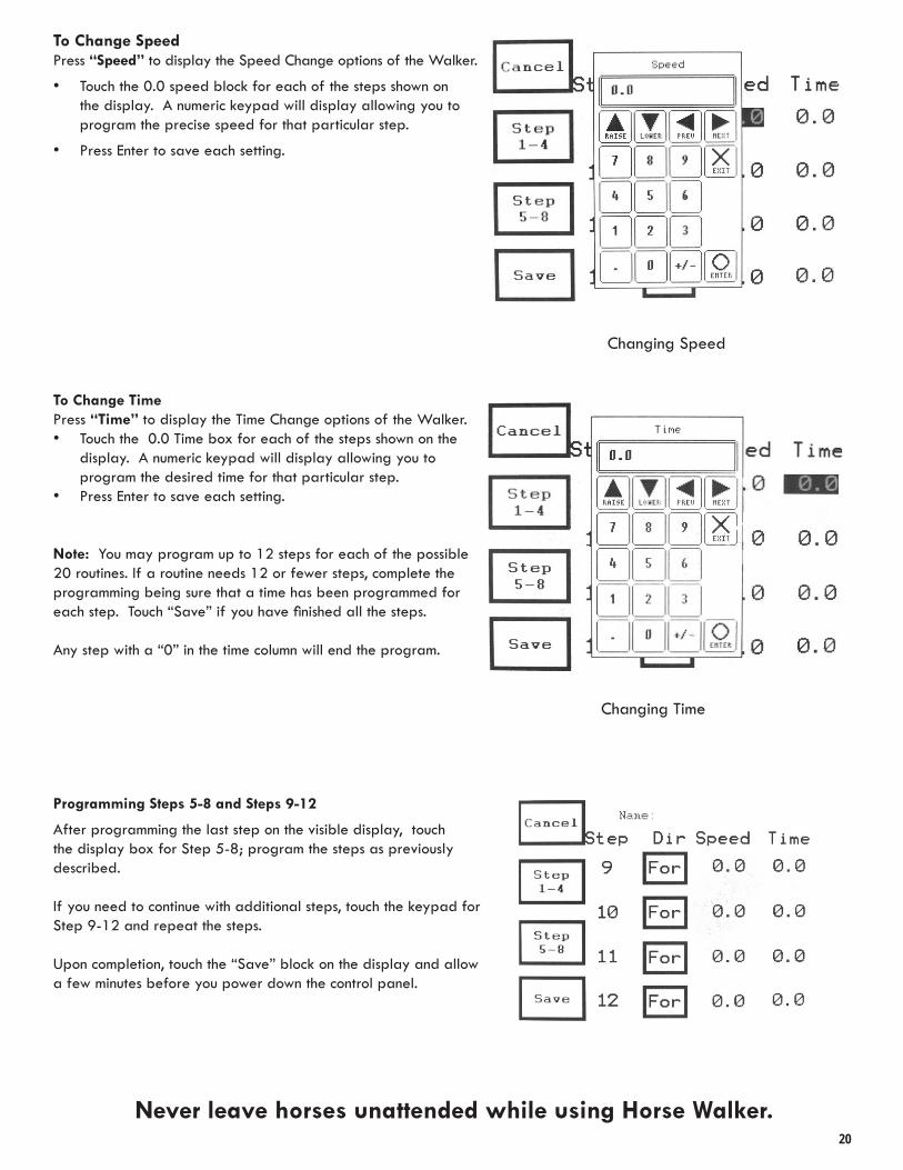
To Change Speed Press “Speed” to display the Speed Change options of the Walker .
• Touch the 0 .0 speed block for each of the steps shown on the display . A numeric keypad will display allowing you to program the precise speed for that particular step .
• Press Enter to save each setting .
To Change TimePress “Time” to display the Time Change options of the Walker . • Touch the 0 .0 Time box for each of the steps shown on the
display . A numeric keypad will display allowing you to program the desired time for that particular step .
• Press Enter to save each setting .
Note: You may program up to 12 steps for each of the possible 20 routines . If a routine needs 12 or fewer steps, complete the programming being sure that a time has been programmed for each step. Touch “Save” if you have finished all the steps.
Any step with a “0” in the time column will end the program .
Programming Steps 5-8 and Steps 9-12
After programming the last step on the visible display, touch the display box for Step 5-8; program the steps as previously described .
If you need to continue with additional steps, touch the keypad for Step 9-12 and repeat the steps .
Upon completion, touch the “Save” block on the display and allow a few minutes before you power down the control panel .
Changing Speed
Changing Time
Never leave horses unattended while using Horse Walker.20

Horse Walker Operation Instructions
Speeds Up Horse Walker
Slows Down Horse Walker
Fault / ResetStops
Horse Walker
Forward/Reverse
Start/Stop
15, 30, & 60 Minute TimerPUSH BUTTON CONTROL PANEL
Horse Walker is programmed to require “reset” if animals stop the walker more than 10 times within 60 seconds, or if the horse is able to stop the walker for a sustained 10 seconds .
When fault light is illuminated, press and hold FAULT button for a minimum of 2 seconds .
If you ever have any problems or difficulty, or have questions about the operation of your Horse Walker, please contact Priefert at 1-800-527-8616 .
No Belts To Burn!
• 25 second “ramp up” time from start to desired speed setting to ease horse into walk .
• 35 second “ramp down” time from engaged to stop .• Remote control that allows the operator to Start/Stop,
change direction (Forward/Reverse), as well as increase or decrease speed; all with a push of a button .
• One of the more unique and outstanding features of this lead walker is the fact that if a horse balks and stops the walker, there is no stress wear on the drive train . The motor simply pauses for a few moments and then restarts . Horses soon respond to the “pressure and release” training and therefore adapt to the Priefert walker with less resistance and no negative impact on the walker itself .
Key Features Fault / Reset
Never leave horses unattended while using Horse Walker.