744-2010 bid opportunity - winnipeg · the system includes sludge withdrawal pipes from the...
TRANSCRIPT
Digester Processes
1. Raw Sludge Pumping System
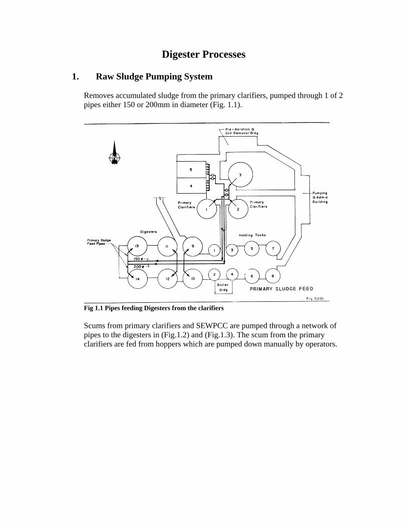
Removes accumulated sludge from the primary clarifiers, pumped through 1 of 2 pipes either 150 or 200mm in diameter (Fig. 1.1).
Fig 1.1 Pipes feeding Digesters from the clarifiers Scums from primary clarifiers and SEWPCC are pumped through a network of pipes to the digesters in (Fig.1.2) and (Fig.1.3). The scum from the primary clarifiers are fed from hoppers which are pumped down manually by operators.
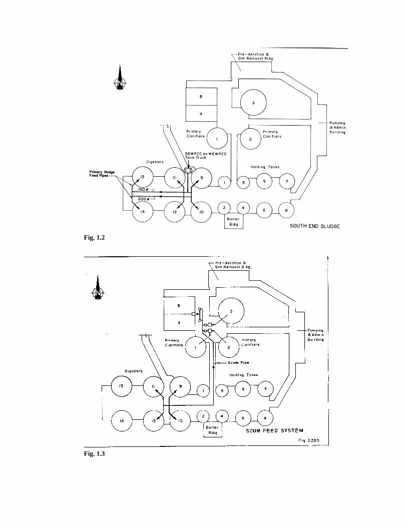
Fig. 1.2
Fig. 1.3
2. Primary Digester Tankage The purpose of sludge digestion is to stabilize organic matter in sludge and render it odour free, disposable and free of disease causing bacteria. Digester 11 has a liquid volume of 7200m3. The tanks have flat bottoms with four hoppers located in the tank bottom for sludge withdrawal. Sledge enters the digester through the recirculating sludge and heat exchanger system. Sludge leaves the digester through the sludge overflow box. Normally the sludge exits the overflow box to the sludge suction piping system in the gallery. If that line is plugged the sludge level will rise and exit the overflow box through the emergency overflow piping to tank #1. Each digester has a sludge heating system. The system includes sludge withdrawal pipes from the digester, sludge and hot water recirculation pumps, a water to sludge heat exchanger and return piping to the digester. Connecting pipes allow the pumps and heat exchanger of one digester to be used for another. Digesters 9 to 12 each contain ten mixing tubes of the confined lift type. Each digester mixing system includes gas withdrawal piping, gas compressor, safety valves and equipment and the gas mixers
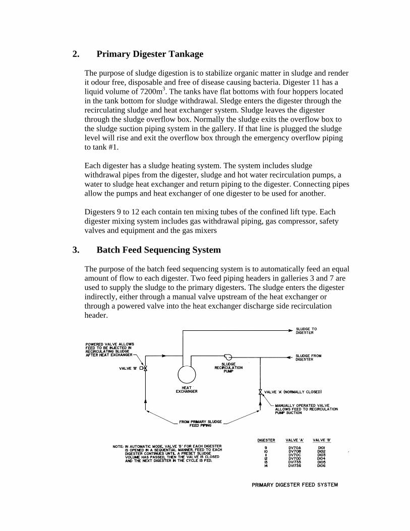
3. Batch Feed Sequencing System The purpose of the batch feed sequencing system is to automatically feed an equal amount of flow to each digester. Two feed piping headers in galleries 3 and 7 are used to supply the sludge to the primary digesters. The sludge enters the digester indirectly, either through a manual valve upstream of the heat exchanger or through a powered valve into the heat exchanger discharge side recirculation header.
4. Sludge Recirculation and Heat Exchangers
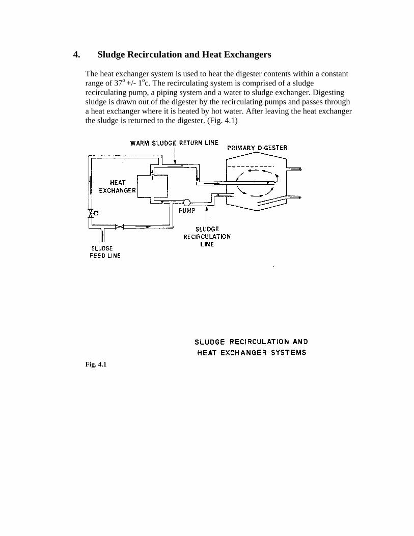
The heat exchanger system is used to heat the digester contents within a constant range of 37o +/- 1oc. The recirculating system is comprised of a sludge recirculating pump, a piping system and a water to sludge exchanger. Digesting sludge is drawn out of the digester by the recirculating pumps and passes through a heat exchanger where it is heated by hot water. After leaving the heat exchanger the sludge is returned to the digester. (Fig. 4.1)
Fig. 4.1
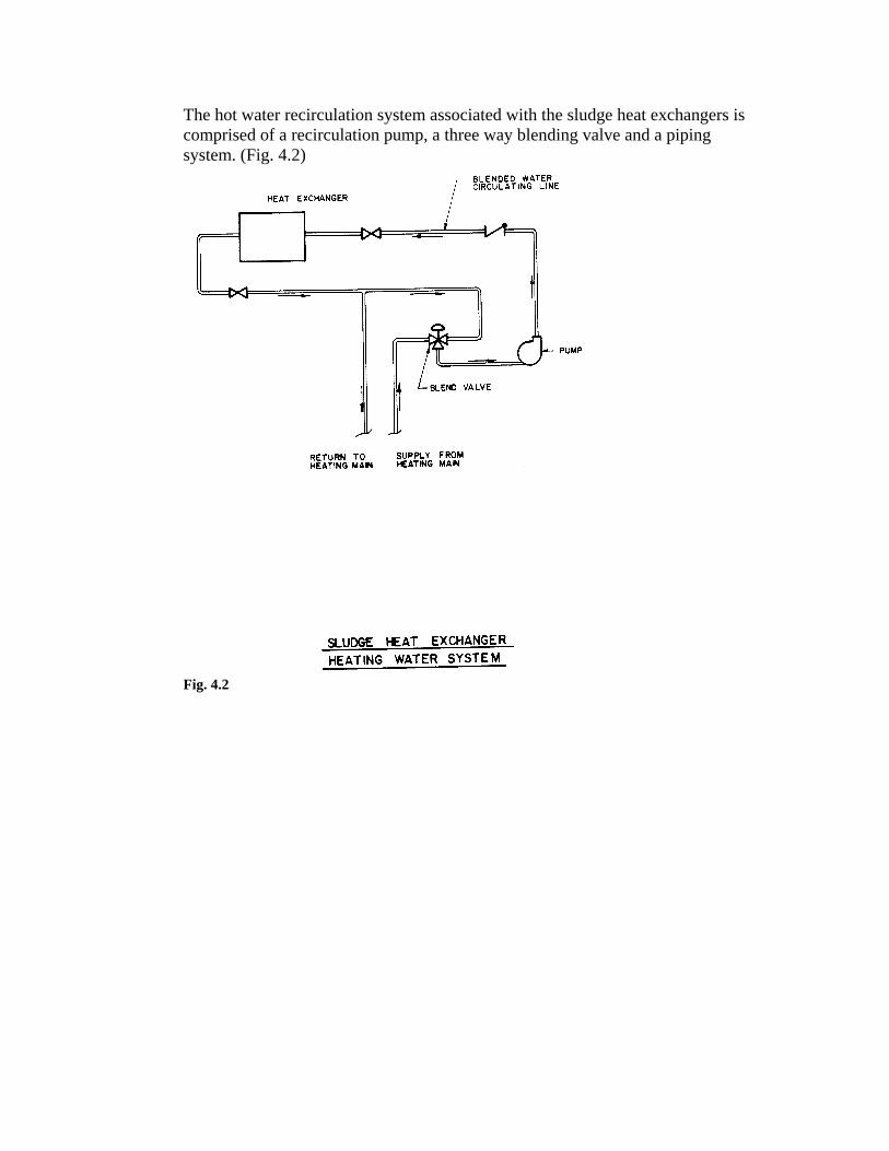
The hot water recirculation system associated with the sludge heat exchangers is comprised of a recirculation pump, a three way blending valve and a piping system. (Fig. 4.2)
Fig. 4.2
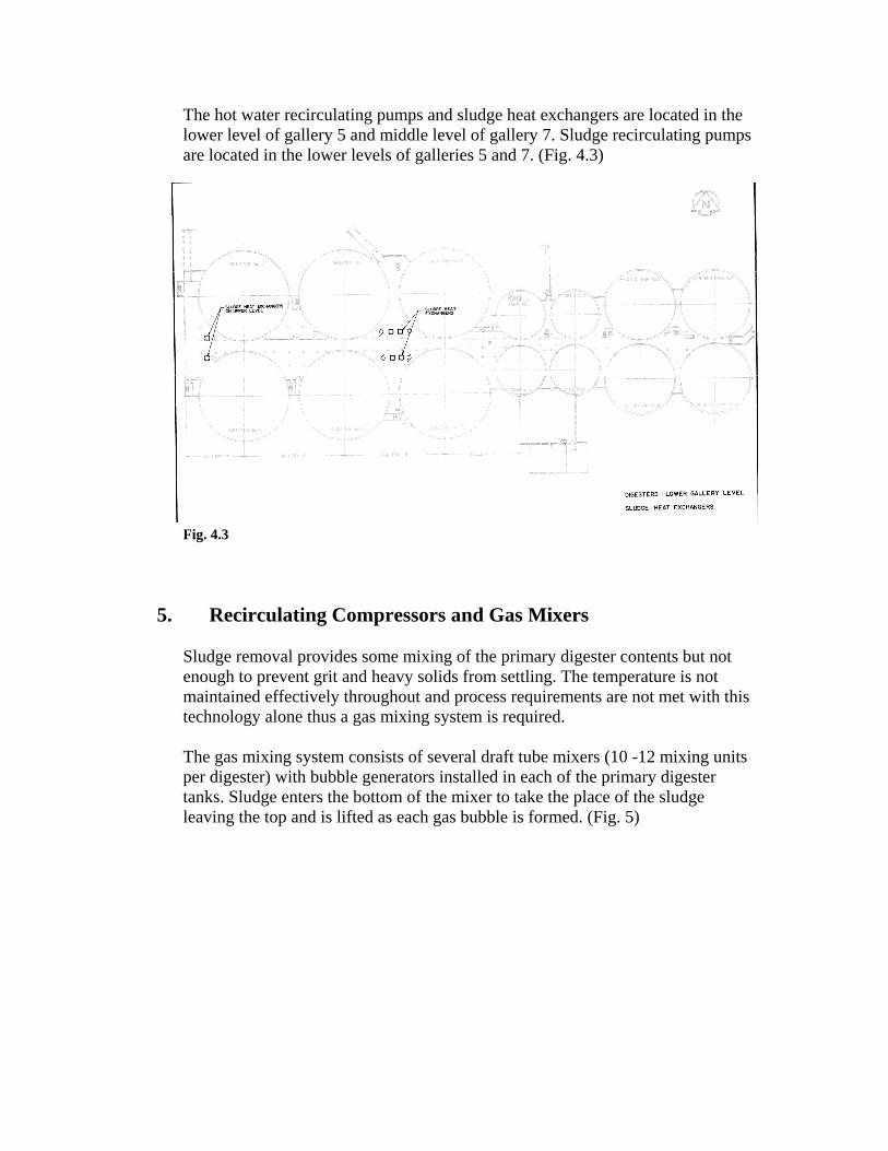
The hot water recirculating pumps and sludge heat exchangers are located in the lower level of gallery 5 and middle level of gallery 7. Sludge recirculating pumps are located in the lower levels of galleries 5 and 7. (Fig. 4.3) Fig. 4.3
5. Recirculating Compressors and Gas Mixers
Sludge removal provides some mixing of the primary digester contents but not enough to prevent grit and heavy solids from settling. The temperature is not maintained effectively throughout and process requirements are not met with this technology alone thus a gas mixing system is required. The gas mixing system consists of several draft tube mixers (10 -12 mixing units per digester) with bubble generators installed in each of the primary digester tanks. Sludge enters the bottom of the mixer to take the place of the sludge leaving the top and is lifted as each gas bubble is formed. (Fig. 5)
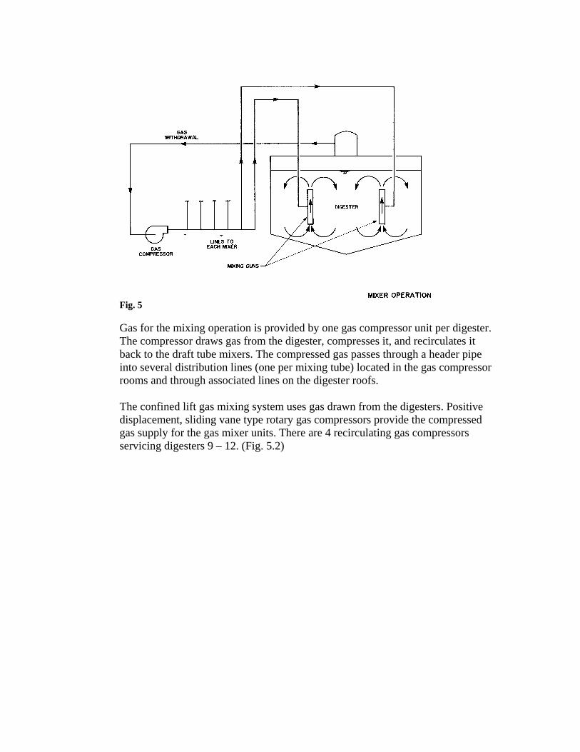
Fig. 5 Gas for the mixing operation is provided by one gas compressor unit per digester. The compressor draws gas from the digester, compresses it, and recirculates it back to the draft tube mixers. The compressed gas passes through a header pipe into several distribution lines (one per mixing tube) located in the gas compressor rooms and through associated lines on the digester roofs. The confined lift gas mixing system uses gas drawn from the digesters. Positive displacement, sliding vane type rotary gas compressors provide the compressed gas supply for the gas mixer units. There are 4 recirculating gas compressors servicing digesters 9 – 12. (Fig. 5.2)
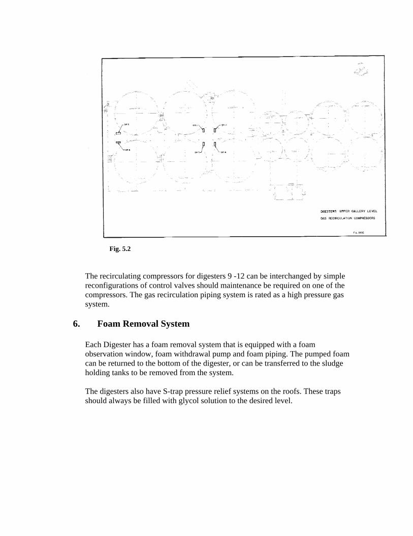
Fig. 5.2
The recirculating compressors for digesters 9 -12 can be interchanged by simple reconfigurations of control valves should maintenance be required on one of the compressors. The gas recirculation piping system is rated as a high pressure gas system.
6. Foam Removal System
Each Digester has a foam removal system that is equipped with a foam observation window, foam withdrawal pump and foam piping. The pumped foam can be returned to the bottom of the digester, or can be transferred to the sludge holding tanks to be removed from the system. The digesters also have S-trap pressure relief systems on the roofs. These traps should always be filled with glycol solution to the desired level.
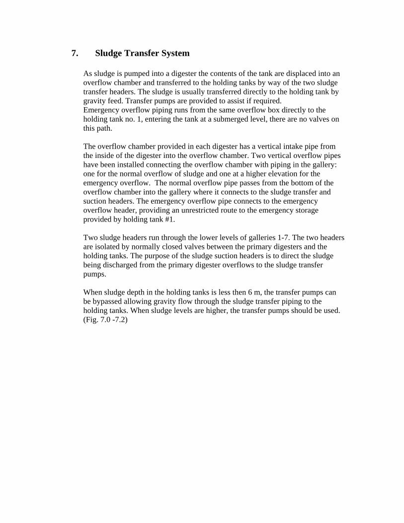
7. Sludge Transfer System
As sludge is pumped into a digester the contents of the tank are displaced into an overflow chamber and transferred to the holding tanks by way of the two sludge transfer headers. The sludge is usually transferred directly to the holding tank by gravity feed. Transfer pumps are provided to assist if required. Emergency overflow piping runs from the same overflow box directly to the holding tank no. 1, entering the tank at a submerged level, there are no valves on this path. The overflow chamber provided in each digester has a vertical intake pipe from the inside of the digester into the overflow chamber. Two vertical overflow pipes have been installed connecting the overflow chamber with piping in the gallery: one for the normal overflow of sludge and one at a higher elevation for the emergency overflow. The normal overflow pipe passes from the bottom of the overflow chamber into the gallery where it connects to the sludge transfer and suction headers. The emergency overflow pipe connects to the emergency overflow header, providing an unrestricted route to the emergency storage provided by holding tank #1. Two sludge headers run through the lower levels of galleries 1-7. The two headers are isolated by normally closed valves between the primary digesters and the holding tanks. The purpose of the sludge suction headers is to direct the sludge being discharged from the primary digester overflows to the sludge transfer pumps. When sludge depth in the holding tanks is less then 6 m, the transfer pumps can be bypassed allowing gravity flow through the sludge transfer piping to the holding tanks. When sludge levels are higher, the transfer pumps should be used. (Fig. 7.0 -7.2)
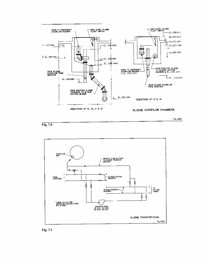
Fig. 7.0
Fig. 7.1
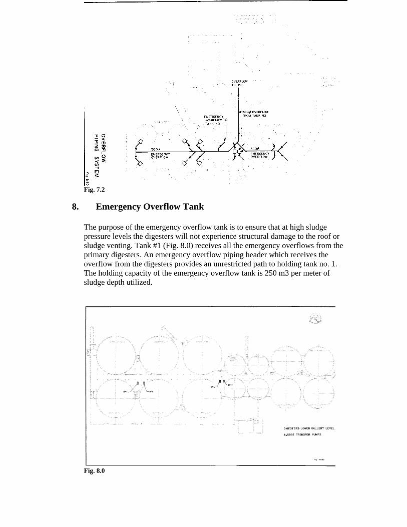
Fig. 7.2
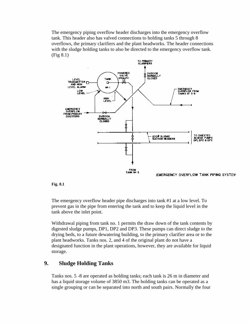
8. Emergency Overflow Tank
The purpose of the emergency overflow tank is to ensure that at high sludge pressure levels the digesters will not experience structural damage to the roof or sludge venting. Tank #1 (Fig. 8.0) receives all the emergency overflows from the primary digesters. An emergency overflow piping header which receives the overflow from the digesters provides an unrestricted path to holding tank no. 1. The holding capacity of the emergency overflow tank is 250 m3 per meter of sludge depth utilized.
Fig. 8.0
The emergency piping overflow header discharges into the emergency overflow tank. This header also has valved connections to holding tanks 5 through 8 overflows, the primary clarifiers and the plant headworks. The header connections with the sludge holding tanks to also be directed to the emergency overflow tank. (Fig 8.1)
Fig. 8.1
The emergency overflow header pipe discharges into tank #1 at a low level. To prevent gas in the pipe from entering the tank and to keep the liquid level in the tank above the inlet point.
Withdrawal piping from tank no. 1 permits the draw down of the tank contents by digested sludge pumps, DP1, DP2 and DP3. These pumps can direct sludge to the drying beds, to a future dewatering building, to the primary clarifier area or to the plant headworks. Tanks nos. 2, and 4 of the original plant do not have a designated function in the plant operations, however, they are available for liquid storage.
9. Sludge Holding Tanks
Tanks nos. 5 -8 are operated as holding tanks; each tank is 26 m in diameter and has a liquid storage volume of 3850 m3. The holding tanks can be operated as a single grouping or can be separated into north and south pairs. Normally the four
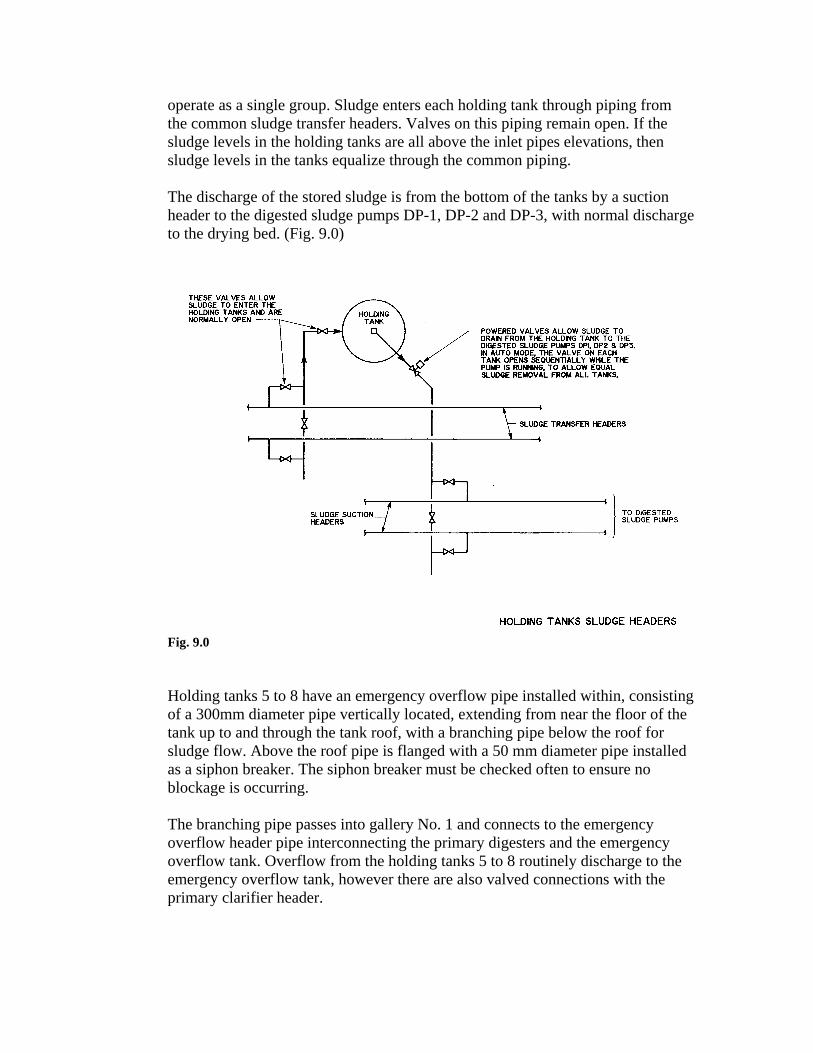
operate as a single group. Sludge enters each holding tank through piping from the common sludge transfer headers. Valves on this piping remain open. If the sludge levels in the holding tanks are all above the inlet pipes elevations, then sludge levels in the tanks equalize through the common piping. The discharge of the stored sludge is from the bottom of the tanks by a suction header to the digested sludge pumps DP-1, DP-2 and DP-3, with normal discharge to the drying bed. (Fig. 9.0)
Fig. 9.0
Holding tanks 5 to 8 have an emergency overflow pipe installed within, consisting of a 300mm diameter pipe vertically located, extending from near the floor of the tank up to and through the tank roof, with a branching pipe below the roof for sludge flow. Above the roof pipe is flanged with a 50 mm diameter pipe installed as a siphon breaker. The siphon breaker must be checked often to ensure no blockage is occurring. The branching pipe passes into gallery No. 1 and connects to the emergency overflow header pipe interconnecting the primary digesters and the emergency overflow tank. Overflow from the holding tanks 5 to 8 routinely discharge to the emergency overflow tank, however there are also valved connections with the primary clarifier header.
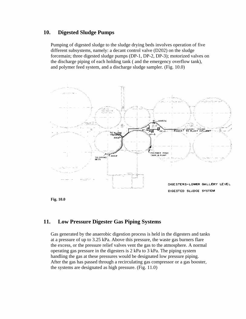
10. Digested Sludge Pumps
Pumping of digested sludge to the sludge drying beds involves operation of five different subsystems, namely: a decant control valve (D202) on the sludge forcemain; three digested sludge pumps (DP-1, DP-2, DP-3); motorized valves on the discharge piping of each holding tank ( and the emergency overflow tank), and polymer feed system, and a discharge sludge sampler. (Fig. 10.0)
Fig. 10.0
11. Low Pressure Digester Gas Piping Systems
Gas generated by the anaerobic digestion process is held in the digesters and tanks at a pressure of up to 3.25 kPa. Above this pressure, the waste gas burners flare the excess, or the pressure relief valves vent the gas to the atmosphere. A normal operating gas pressure in the digesters is 2 kPa to 3 kPa. The piping system handling the gas at these pressures would be designated low pressure piping. After the gas has passed through a recirculating gas compressor or a gas booster, the systems are designated as high pressure. (Fig. 11.0)
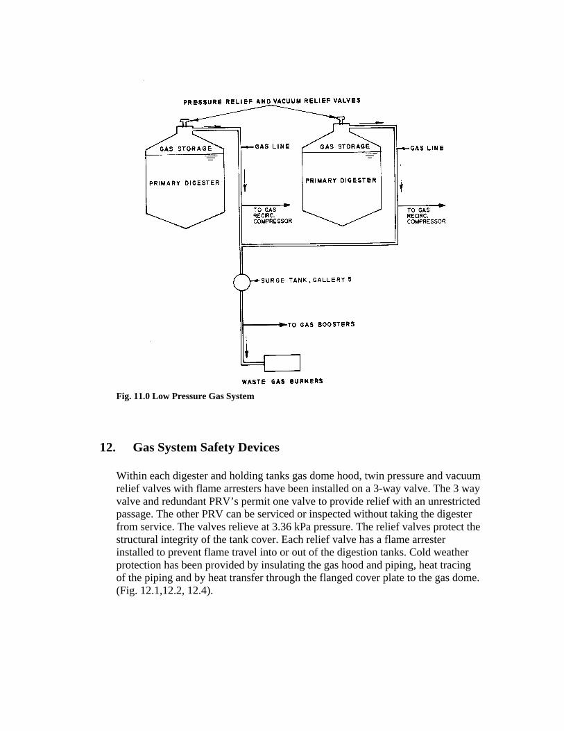
Fig. 11.0 Low Pressure Gas System
12. Gas System Safety Devices
Within each digester and holding tanks gas dome hood, twin pressure and vacuum relief valves with flame arresters have been installed on a 3-way valve. The 3 way valve and redundant PRV’s permit one valve to provide relief with an unrestricted passage. The other PRV can be serviced or inspected without taking the digester from service. The valves relieve at 3.36 kPa pressure. The relief valves protect the structural integrity of the tank cover. Each relief valve has a flame arrester installed to prevent flame travel into or out of the digestion tanks. Cold weather protection has been provided by insulating the gas hood and piping, heat tracing of the piping and by heat transfer through the flanged cover plate to the gas dome. (Fig. 12.1,12.2, 12.4).
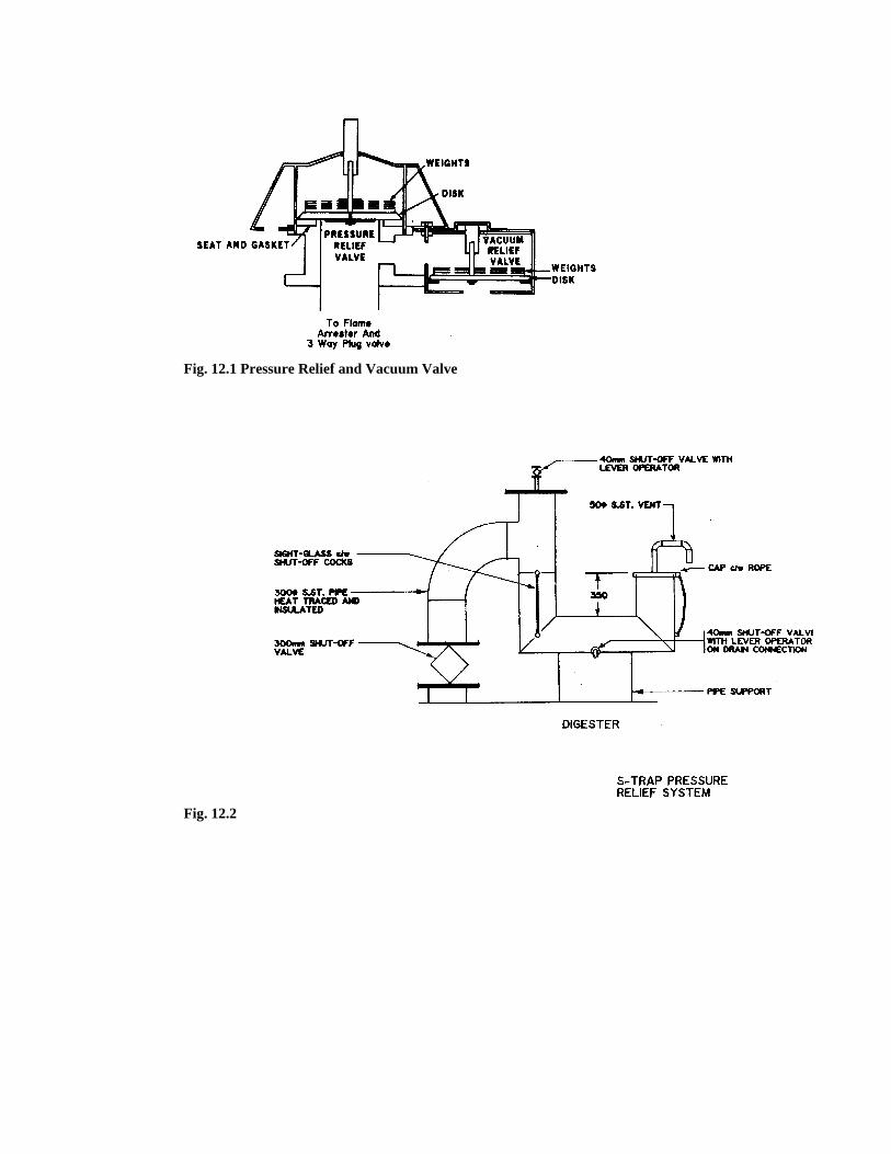
Fig. 12.1 Pressure Relief and Vacuum Valve
Fig. 12.2
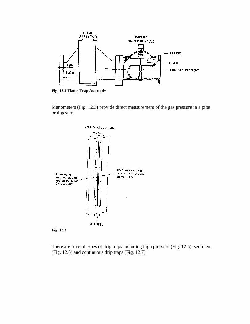
Fig. 12.4 Flame Trap Assembly
Manometers (Fig. 12.3) provide direct measurement of the gas pressure in a pipe or digester.
Fig. 12.3
There are several types of drip traps including high pressure (Fig. 12.5), sediment (Fig. 12.6) and continuous drip traps (Fig. 12.7).
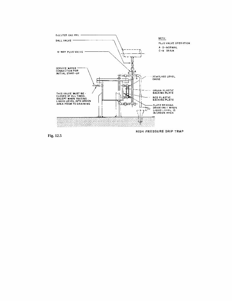
Fig. 12.5
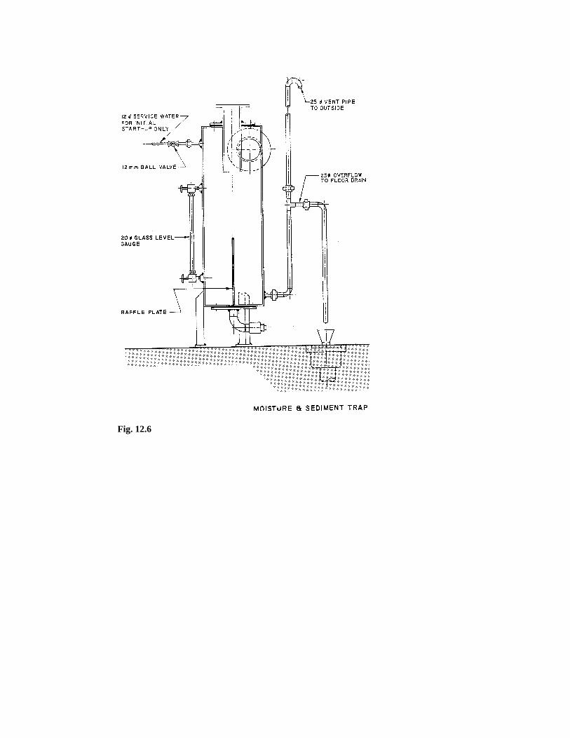
Fig. 12.6
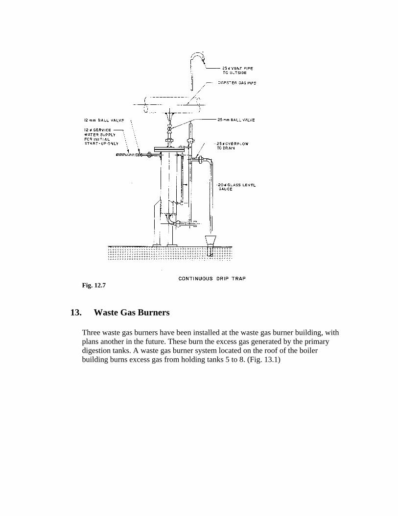
Fig. 12.7
13. Waste Gas Burners
Three waste gas burners have been installed at the waste gas burner building, with plans another in the future. These burn the excess gas generated by the primary digestion tanks. A waste gas burner system located on the roof of the boiler building burns excess gas from holding tanks 5 to 8. (Fig. 13.1)
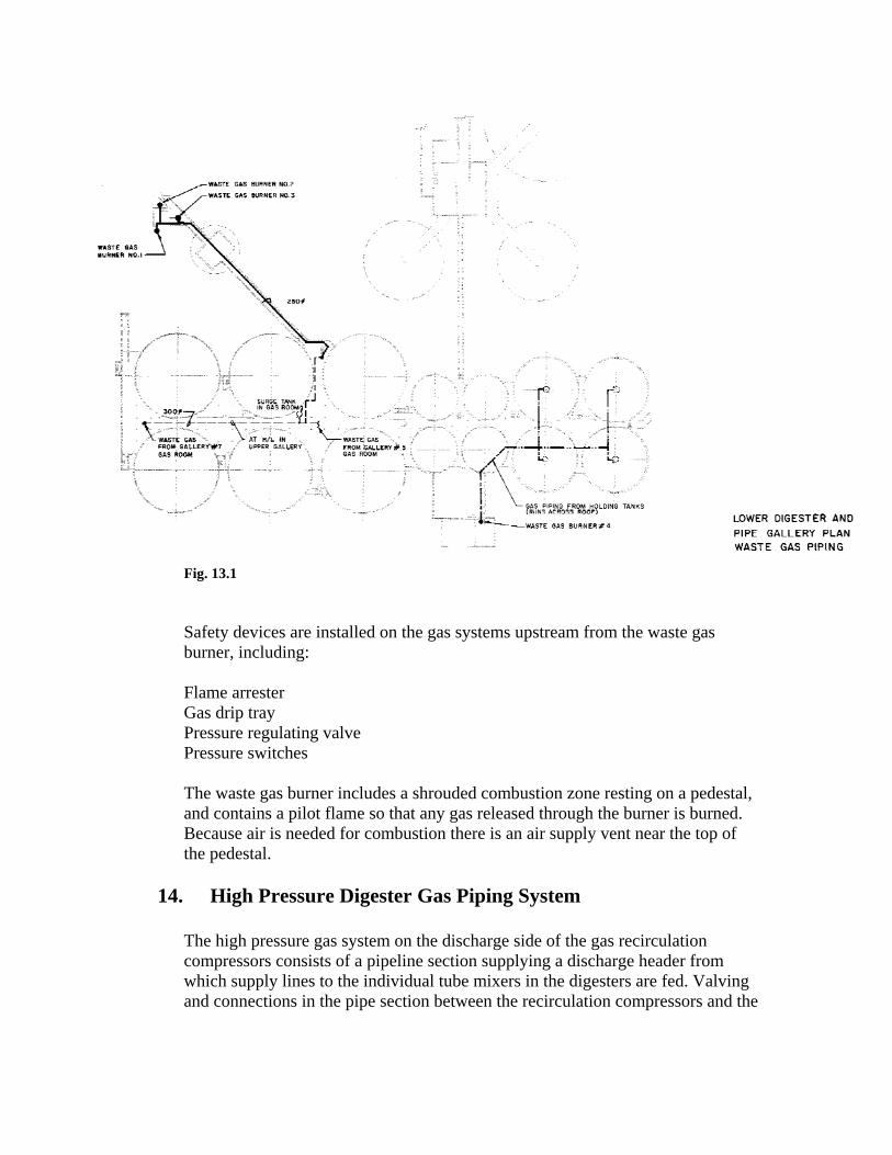
Fig. 13.1
Safety devices are installed on the gas systems upstream from the waste gas burner, including: Flame arrester Gas drip tray Pressure regulating valve Pressure switches The waste gas burner includes a shrouded combustion zone resting on a pedestal, and contains a pilot flame so that any gas released through the burner is burned. Because air is needed for combustion there is an air supply vent near the top of the pedestal.
14. High Pressure Digester Gas Piping System
The high pressure gas system on the discharge side of the gas recirculation compressors consists of a pipeline section supplying a discharge header from which supply lines to the individual tube mixers in the digesters are fed. Valving and connections in the pipe section between the recirculation compressors and the
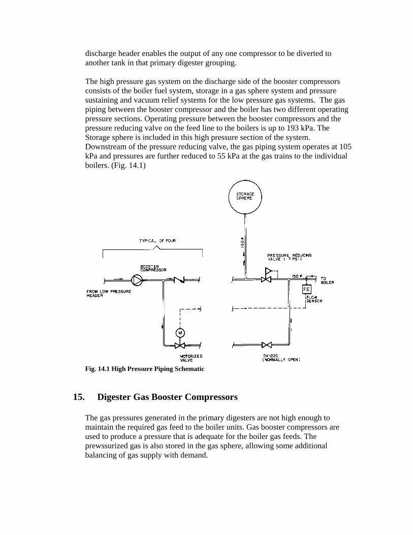
discharge header enables the output of any one compressor to be diverted to another tank in that primary digester grouping. The high pressure gas system on the discharge side of the booster compressors consists of the boiler fuel system, storage in a gas sphere system and pressure sustaining and vacuum relief systems for the low pressure gas systems. The gas piping between the booster compressor and the boiler has two different operating pressure sections. Operating pressure between the booster compressors and the pressure reducing valve on the feed line to the boilers is up to 193 kPa. The Storage sphere is included in this high pressure section of the system. Downstream of the pressure reducing valve, the gas piping system operates at 105 kPa and pressures are further reduced to 55 kPa at the gas trains to the individual boilers. (Fig. 14.1)
Fig. 14.1 High Pressure Piping Schematic
15. Digester Gas Booster Compressors
The gas pressures generated in the primary digesters are not high enough to maintain the required gas feed to the boiler units. Gas booster compressors are used to produce a pressure that is adequate for the boiler gas feeds. The prewssurized gas is also stored in the gas sphere, allowing some additional balancing of gas supply with demand.
The gas boosters pressurize the primary digester gas up to 200 kPa. The boosters are of the positive displacement, rotary sliding vane type, and are of equal capacity output. The operations of the 4 gas booster are controlled by automatic sequencing logic based on the surge tank gas pressure, gas sphere pressure and boiler fuel demand. Three booster compressors are located in the gas room of gallery 5. A fourth booster is located in the gas room of gallery 7.
16. Holding Tanks Gas System
Sludge transferred into the holding tanks 5 to 8 has reached the final stage of the anaerobic digestion process. However, gas handling facilities are required as volatile acid and methane forming bacteria still exist and can still create digester gas. Holding tanks 5 to 8 are serviced by a waste gas burner and a pressure sustaining and vacuum relief gas padding system separate from the primary digester tanks. The holding tanks low pressure gas system is completely separate from that of the primary digester tanks to enable it to operate at lower gas pressures. A separate gas system exists for the holding tanks 5 to 8. The gas piping system is similar to the digesters gas collection system, with all gas equipment installed as required by the B105 gas code. The gas however is simply relieved at excess pressures through a waste gas burner installed specifically for the holding tanks gas system. Pressure and vacuum relief valves are provided for each holding tank inside of the ga domes. Tanks 5 to 8 are connected by gas withdrawal piping to a common gas header which results in equalization of gas pressures in all the connected holding tanks. Equalization provides some protection against vacuum conditions resulting from the lowering of the sludge liquid level in any of the tanks. There is a concern that vacuum conditions could occur in the tanks when the sludge levels are lowered as past of the normal holding tanks operation. If the gas dome relief valves were to open, air could enter the holding tanks operations. If the gas dome relief valves were to open, air could enter the holding tank gas space, possibly creating a flammable mixture. An additional pressure sustaining and vacuum relief padding system protects against this by maintaining a minimum pressure in each tank. When liquid levels are lowered, tank gas pressures decrease. At low pressures, the gas spaces are padded with digester gas from the pressurized storage sphere system into the holding tanks system. The connection is located above the boiler room area. Waste Gas Burner Through burning, gas odours are destroyed. The common gas header of the holding tanks is piped to a single gas burner located on the boiler building roof. The burner consists of
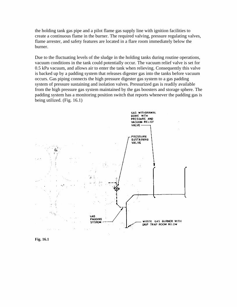
the holding tank gas pipe and a pilot flame gas supply line with ignition facilities to create a continuous flame in the burner. The required valving, pressure regulating valves, flame arrester, and safety features are located in a flare room immediately below the burner. Due to the fluctuating levels of the sludge in the holding tanks during routine operations, vacuum conditions in the tank could potentially occur. The vacuum relief valve is set for 0.5 kPa vacuum, and allows air to enter the tank when relieving. Consequently this valve is backed up by a padding system that releases digester gas into the tanks before vacuum occurs. Gas piping connects the high pressure digester gas system to a gas padding system of pressure sustaining and isolation valves. Pressurized gas is readily available from the high pressure gas system maintained by the gas boosters and storage sphere. The padding system has a monitoring position switch that reports whenever the padding gas is being utilized. (Fig. 16.1)
Fig. 16.1