7 ton log splitter · 7 ton log splitter. 1 rev 90720-20130226 english 90720 ... champion power...
TRANSCRIPT

OWNER’S MANUAL AND OPERATING INSTRUCTIONS
7 TonLOG SPLITTER
10006 Santa Fe Springs RoadSanta Fe Springs CA 90670
USA / 1-877-338-0999www.championpowerequipment.com
SAVE THESE INSTRUCTIONS Important Safety Instructions are included in this manual.
MADE IN CHINAREV 90720-20130226
90720MODEL NUMBER

*We are always working to improve our products. Therefore, the enclosed product may differ slightly from the image on the cover.
WARNING:The Engine Exhaust from this product contains chemicals known to the State of California
to cause cancer, birth defects or other reproductive harm.
Have questions or need assistance?Do not return this product to the store!
WE ARE HERE TO HELP!Visit our website:
www.championpowerequipment.comfor more info:
• Product Info & Updates• Frequently Asked Questions
• Tech Bulletins• Product Registration
– or –
Call our Customer Care Team Toll-Free at:
1-877-338-0999
AN IMPORTANT MESSAGE ABOUT TEMPERATURE:Your Champion Power Equipment product is designed and rated for continuous operation at ambient temperatures up to 40°C (104°F). When your product is needed your product may be operated at temperatures ranging from -15°C (5°F) to 50°C (122°F) for short periods. If the product is exposed to temperatures outside this range during storage, it should be brought back within this range before operation. In any event, the product must always be operated outdoors, in a well-ventilated area and away from doors, windows and other vents.
90720
TABLE OF CONTENTSIntroduction . . . . . . . . . . . . . . . . . . . . . . . . . . . . 1
Introduction . . . . . . . . . . . . . . . . . . . . . . . . . . 1Portable Log Splitter . . . . . . . . . . . . . . . . . . . . 1Accessories . . . . . . . . . . . . . . . . . . . . . . . . . . 1This Booklet . . . . . . . . . . . . . . . . . . . . . . . . . . 1
Manual Conventions . . . . . . . . . . . . . . . . . . . . . . . 2Safety Rules . . . . . . . . . . . . . . . . . . . . . . . . . . . . 3
Training . . . . . . . . . . . . . . . . . . . . . . . . . . . . . 5Preparation . . . . . . . . . . . . . . . . . . . . . . . . . . 5Operation . . . . . . . . . . . . . . . . . . . . . . . . . . . . 6Maintenance and Storage . . . . . . . . . . . . . . . . . 6
Controls and Features . . . . . . . . . . . . . . . . . . . . . 7Log Splitter . . . . . . . . . . . . . . . . . . . . . . . . . . 7
Assembly . . . . . . . . . . . . . . . . . . . . . . . . . . . . . . 8Open Shipping Crate . . . . . . . . . . . . . . . . . . . . 81) Install the Wheels to the Wheel Mount . . . . . . 82) Install the Support Foot . . . . . . . . . . . . . . . . 83) Install the Beam onto the Wheel Mount . . . . . 84) Install the Engine to the Wheel Mount . . . . . . 85) Install the Cylinder to the Beam . . . . . . . . . . 96) Install the Ram Bracket to the Cylinder . . . . . 97) Install the Handle . . . . . . . . . . . . . . . . . . . . 98) Install the Hoses . . . . . . . . . . . . . . . . . . . . . 9Add Engine Oil . . . . . . . . . . . . . . . . . . . . . . . 10Add Hydraulic Oil . . . . . . . . . . . . . . . . . . . . . 10Add Engine Fuel . . . . . . . . . . . . . . . . . . . . . . 11
Operation . . . . . . . . . . . . . . . . . . . . . . . . . . . . . 12Before Each Use Inspect the Log Splitter . . . . . 12Log Splitter Location . . . . . . . . . . . . . . . . . . . 12Starting the Engine . . . . . . . . . . . . . . . . . . . . 13Stopping the Engine . . . . . . . . . . . . . . . . . . . 13Log Splitter Operation . . . . . . . . . . . . . . . . . . 13
Maintenance and Storage . . . . . . . . . . . . . . . . . . 15Engine Maintenance . . . . . . . . . . . . . . . . . . . 15
Oil . . . . . . . . . . . . . . . . . . . . . . . . . . . . . 15Spark Plugs . . . . . . . . . . . . . . . . . . . . . . . 15Air Filter . . . . . . . . . . . . . . . . . . . . . . . . . 15
Log Splitter Maintenance . . . . . . . . . . . . . . . . 15
Cleaning . . . . . . . . . . . . . . . . . . . . . . . . . . . 16Maintenance Schedule . . . . . . . . . . . . . . . . . . 16Hydraulic Oil . . . . . . . . . . . . . . . . . . . . . . . . 16Storage . . . . . . . . . . . . . . . . . . . . . . . . . . . . 17
Log Splitter Storage . . . . . . . . . . . . . . . . . 17Engine stored for Less than 30 Days . . . . . . 17Engines Stored for Over 30 Days . . . . . . . . . 17
Specifications . . . . . . . . . . . . . . . . . . . . . . . . . . 18Log Splitter Specifications . . . . . . . . . . . . . . . 18Engine Specifications . . . . . . . . . . . . . . . . . . 18Spark Plugs . . . . . . . . . . . . . . . . . . . . . . . . . 18Maintenance Valve Clearance . . . . . . . . . . . . . 18Hydraulic Oil System . . . . . . . . . . . . . . . . . . . 18Fuel . . . . . . . . . . . . . . . . . . . . . . . . . . . . . . 18Oil . . . . . . . . . . . . . . . . . . . . . . . . . . . . . . . 18An Important Message About Temperature . . . . 18Parts Diagram . . . . . . . . . . . . . . . . . . . . . . . . 19Parts List . . . . . . . . . . . . . . . . . . . . . . . . . . . 20Engine Parts Diagram . . . . . . . . . . . . . . . . . . 21Engine Parts List . . . . . . . . . . . . . . . . . . . . . 22
Troubleshooting . . . . . . . . . . . . . . . . . . . . . . . . . 23Warranty . . . . . . . . . . . . . . . . . . . . . . . . . . . . . 24
Warranty Qualifications . . . . . . . . . . . . . . . . . 24Repair/Replacement Warranty . . . . . . . . . . . . . 24Do Not Return The UnitTo The Place Of Purchase . . . . . . . . . . . . . . . 24Warranty Exclusions. . . . . . . . . . . . . . . . . . . . 24
Normal Wear . . . . . . . . . . . . . . . . . . . . . . 24Installation, Use and Maintenance . . . . . . . . 24Other Exclusions . . . . . . . . . . . . . . . . . . . . 24Limits of Implied Warrantyand Consequential Damage . . . . . . . . . . . . 24
Contact Information . . . . . . . . . . . . . . . . . . . . 24Address . . . . . . . . . . . . . . . . . . . . . . . . . . 24Customer Service . . . . . . . . . . . . . . . . . . . 24Technical Service . . . . . . . . . . . . . . . . . . . 24
7 Ton
LOG SPLITTER
1 REV 90720-20130226
ENGLISH 90720
INTROdUCTION
IntroductionCongratulations on your purchase of a Champion
Power Equipment log splitter. CPE designs and builds
log splitters to strict specifications. With proper use
and maintenance, this log splitter will bring years of
satisfying service.
Portable Log SplitterThis unit is a gasoline engine driven hydraulic log splitter.
It is designed to split wood logs for use as firewood for
a stove or fireplace. This log splitter will only split logs
lengthwise, with the grain only.
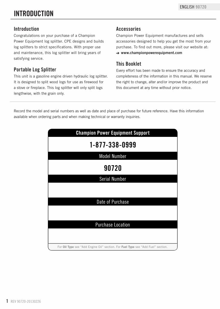
Record the model and serial numbers as well as date and place of purchase for future reference. Have this information
available when ordering parts and when making technical or warranty inquiries.
AccessoriesChampion Power Equipment manufactures and sells
accessories designed to help you get the most from your
purchase. To find out more, please visit our website at:
www.championpowerequipment.com
This BookletEvery effort has been made to ensure the accuracy and
completeness of the information in this manual. We reserve
the right to change, alter and/or improve the product and
this document at any time without prior notice.
Champion Power Equipment Support
Model Number
Serial Number
Date of Purchase
Purchase Location
1-877-338-0999
90720
For Oil Type see “Add Engine Oil” section. For Fuel Type see “Add Fuel” section.
REV 90720-20130226 2
90720 ENGLISH
MANUAL CONVENTIONS
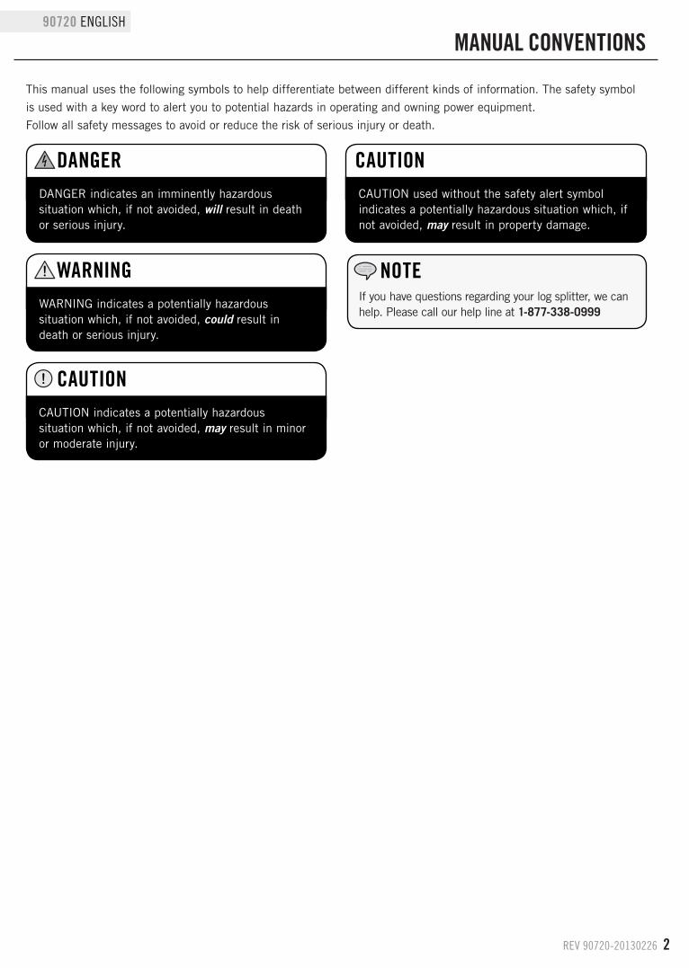
CAUTION indicates a potentially hazardous situation which, if not avoided, may result in minor or moderate injury.
CAUTION
CAUTION used without the safety alert symbol indicates a potentially hazardous situation which, if not avoided, may result in property damage.
CAUTION
This manual uses the following symbols to help differentiate between different kinds of information. The safety symbol
is used with a key word to alert you to potential hazards in operating and owning power equipment.
Follow all safety messages to avoid or reduce the risk of serious injury or death.
DANGER indicates an imminently hazardous situation which, if not avoided, will result in death or serious injury.
dANGER
WARNING indicates a potentially hazardous situation which, if not avoided, could result in death or serious injury.
WARNINGIf you have questions regarding your log splitter, we can help. Please call our help line at 1-877-338-0999
NOTE
3 REV 90720-20130226
ENGLISH 90720
SAFETy RULES
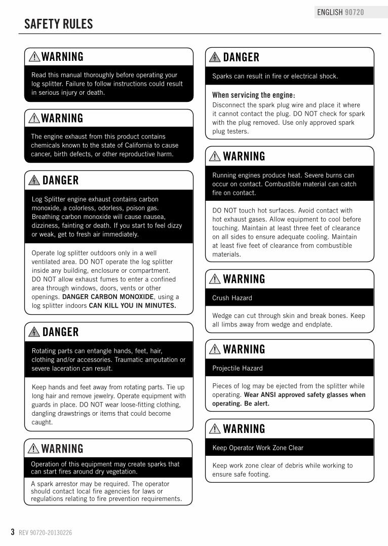
Log Splitter engine exhaust contains carbon monoxide, a colorless, odorless, poison gas. Breathing carbon monoxide will cause nausea, dizziness, fainting or death. If you start to feel dizzy or weak, get to fresh air immediately.
Rotating parts can entangle hands, feet, hair, clothing and/or accessories. Traumatic amputation or severe laceration can result.
dANGER
dANGER
Operate log splitter outdoors only in a well ventilated area. DO NOT operate the log splitter inside any building, enclosure or compartment.DO NOT allow exhaust fumes to enter a confined area through windows, doors, vents or other openings. DANGER CARBON MONOXIDE, using a log splitter indoors CAN KILL YOU IN MINUTES.
Keep hands and feet away from rotating parts. Tie up long hair and remove jewelry. Operate equipment with guards in place. DO NOT wear loose-fitting clothing, dangling drawstrings or items that could become caught.
The engine exhaust from this product contains chemicals known to the state of California to cause cancer, birth defects, or other reproductive harm.
Read this manual thoroughly before operating your log splitter. Failure to follow instructions could result in serious injury or death.
WARNING
WARNING
Sparks can result in fire or electrical shock.
dANGER
When servicing the engine:Disconnect the spark plug wire and place it where it cannot contact the plug. DO NOT check for spark with the plug removed. Use only approved spark plug testers.
Running engines produce heat. Severe burns can occur on contact. Combustible material can catch fire on contact.
DO NOT touch hot surfaces. Avoid contact with hot exhaust gases. Allow equipment to cool before touching. Maintain at least three feet of clearance on all sides to ensure adequate cooling. Maintain at least five feet of clearance from combustible materials.
Crush Hazard
Wedge can cut through skin and break bones. Keep all limbs away from wedge and endplate.
WARNING
WARNING
Projectile Hazard
Pieces of log may be ejected from the splitter while operating. Wear ANSI approved safety glasses when operating. Be alert.
WARNING
Keep Operator Work Zone Clear
Keep work zone clear of debris while working to ensure safe footing.
WARNING
Operation of this equipment may create sparks that can start fires around dry vegetation.
A spark arrestor may be required. The operator should contact local fire agencies for laws or regulations relating to fire prevention requirements.
WARNING
REV 90720-20130226 4
90720 ENGLISH
SAFETy RULES
Fuel and fuel vapors are highly flammable and extremely explosive. Fire or explosion can cause severe burns or death.Unintentional startup can result in entanglement, traumatic amputation or laceration.
dANGER
When adding or removing fuel:Turn the engine off and let it cool for at least two minutes before removing the fuel cap. Loosen the cap slowly to relieve pressure in the tank.Only fill or drain fuel outdoors in a well-ventilated area.DO NOT pump gas directly into the engine at the gas station. Use an approved container to transfer the fuel to the engine.DO NOT overfill the fuel tank.Always keep fuel away from sparks, open flames, pilot lights, heat and other sources of ignition.DO NOT light or smoke cigarettes.
When starting the engine:DO NOT attempt to start a damaged engine. Make certain that the gas cap, air filter, spark plug, fuel lines and exhaust system are properly in place. Allow spilled fuel to evaporate fully before attempting to start the engine. Make certain that the log splitter is resting firmly on level ground.
When operating the log splitter:DO NOT move or tip the log splitter during operation.DO NOT tip the log splitter or allow fuel or oil to spill from the engine. Block the wheels to prevent unintended movement.
When transporting or servicing the log splitter:Make certain that the fuel shutoff valve is in the off position and the fuel tank is empty.
Disconnect the spark plug wire.
When storing the log splitter:Store away from sparks, open flames, pilot lights, heat and other sources of ignition.
Skin Injection Hazard. High pressure hydraulic oil can inject under your skin.
dANGER
Make sure all fittings are tightly secure before applying pressure. Relieve system of pressure before servicing.
Towing Hazard
ALWAYS check all local and state regulations regarding towing, licensing and lights before towing your log splitter. Review towing safety warnings in your towing vehicle manual.Drive safely. Be aware of the added length of the log splitter. NEVER ride or transport cargo on the log splitter. Choose a level surface to operate the log splitter. NEVER EXCEED MAX. Towing Speed 15 MPH (24 KPH)
WARNING
Rapid retraction of the starter cord will pull hand and arm towards the engine faster than you can let go. Unintentional startup can result in entanglement, traumatic amputation or laceration. Broken bones, fractures, bruises or sprains could result.
When starting engine, pull the starter cord slowly until resistance is felt and then pull rapidly to avoid kickback.
WARNING
Improper treatment or use of the log splitter can damage it, shorten its life and void your warranty.
Use the log splitter only for intended uses. Operate only on level surfaces. DO NOT expose log splitter to excessive moisture, dust, or dirt.DO NOT allow any material to block the cooling slots. DO NOT use the engine if: – Equipment sparks, smokes or emits flames – Equipment vibrates excessively
CAUTIONParts of the hydraulic circuit (cylinder, pump, valve-body, hoses) can become very hot during operation.
CAUTION
5 REV 90720-20130226
ENGLISH 90720
Training1. Read the Operator’s Manual completely before
attempting to use this log splitter.
2. Do not allow anyone to operate your log splitter who
has not read the Operator’s Manual or has not been
instructed on the safe use of the log splitter.
3. Never allow children or untrained adults to operate
this machine.
4. Many accidents occur when more than one (1)
person operates the log splitter. If a helper is
assisting in loading logs to be split, never actuate
controls until helper is clear of the area.
5. Never allow anyone to ride on the machine.
6. Never transport cargo on the log splitter.
7. High fluid pressures are developed in hydraulic
log splitters. Pressurized hydraulic fluid escaping
through a pin hole opening can puncture skin
and cause sever blood poisoning. Therefore, the
following instructions should be heeded at all times.
a. Do not operate the unit with frayed, kinked,
cracked or damaged hoses, fittings, or tubing.
b. Stop the engine and relieve hydraulic system
pressure before changing or adjusting fittings,
hoses, tubing, or other system components.
c. Do not adjust the pressure settings of the
pump or valve.
d. Do not check for leaks with your hand. Leaks
can be detected by passing cardboard or wood
over the suspected area. Look for discoloration.
If injured by escaping fluid, see a doctor at
once. Serious infection or reaction can develop
if proper medical treatment is not administered
immediately.
8. Keep the operator zone and adjacent area clear for
safe, secure footing.
9. If your log splitter is equipped with an internal-
combustion engine and intended for use near any
unimproved forest, brush, or grass covered land,
the engine exhaust should be equipped with a spark
arrestor. Make sure you comply with local, state,
and federal codes. Take appropriate fire-fighting
equipment with you.
10. Log splitters should be used only for splitting
wood. Do not use for other purposes unless
the manufacturer provides attachments and
instructions.
SAFETy RULES
Preparation1. Be thoroughly familiar with all controls and with
proper use of the equipment.
2. Safety Gear:
a. Always wear safety shoes or heavy boots when
operating the machine.
b. Always wear safety glasses or goggles when
operating the machine.
c. Never wear jewelry or loose-fitting clothing that
might become entangled in moving or rotating
parts of the machine.
3. Make sure the splitter is on a level surface. Block
tires and ensure support leg is secure to prevent
unintended movement of the log splitter during
operation.
a. Always operate the splitter from the
manufacturer’s indicated operator zone.4. Logs to be split on ram-type units should be cut as
squarely as possible.
5. Fuel:
a. Use an approved fuel container.
b. Never add fuel to a running or hot engine.
c. Fill fuel tank outdoors with extreme care.
Never fill fuel tank indoors.
d. Replace gasoline cap securely and clean up
any spilled fuel.

REV 90720-20130226 6
90720 ENGLISH
SAFETy RULES
Maintenance and Storage1. Always shut off the power source while repairing or
adjusting the splitter except as recommended by the
manufacturer.
2. Clean debris and chaff from the engine cylinder,
cylinder head fins, recoil starter cover, and muffler
areas. If the engine is equipped with a spark
arrestor muffler, clean and inspect it regularly
(follow manufacturer’s service instructions).
Replace, if damaged.
3. Never store the unit indoors with fuel in the tank.
Fumes might reach an open flame spark. Allow the
engine to cool before storing in any enclosure.
4. Clear debris from moveable parts, but only when the
power source is shut off.
5. Check to be sure all nuts and bolts are tight to
assure the equipment is in safe working condition.
Operation1. Before starting this log splitter, review all safety
rules. Failure to follow these rules may result in
serious injury to the operator or bystanders.
2. Be sure to confirm all hose connections and hose
clamps are tight before each use. It is possible for
connections to vibrate loose over time.
3. Never leave the machine unattended with the power
source operating.
4. Never operate the machine when under the
influence of alcohol, drugs or medication.
5. The machine owner should instruct all operators in
safe log splitter operation.
6. Always operate the log splitter with all safety
equipment in place and all controls properly
adjusted for safe operation.
7. Always operate the log splitter at manufacturer’s
recommended speed.
8. Always keep hands and feet clear of moving parts.
9. When loading a ram-type log splitter, place your
hands on the sides of the log, not the ends. Never
place your hands or any part of your body between a
log and any part of the log splitter.
10. On ram-type log splitters, never attempt to split
more than one (1) log at a time unless the ram has
been fully extended and a second log is needed to
complete the separation of the first log.11. On ram-type log splitters on which the logs are not
cut square, the longest portion of the log should be rotated down and the most square end placed against the ram.
12. Use only your hand to operate the log splitter controls.
13. Do not refuel the engine until it has cooled for several minutes.
7 REV 90720-20130226
ENGLISH 90720
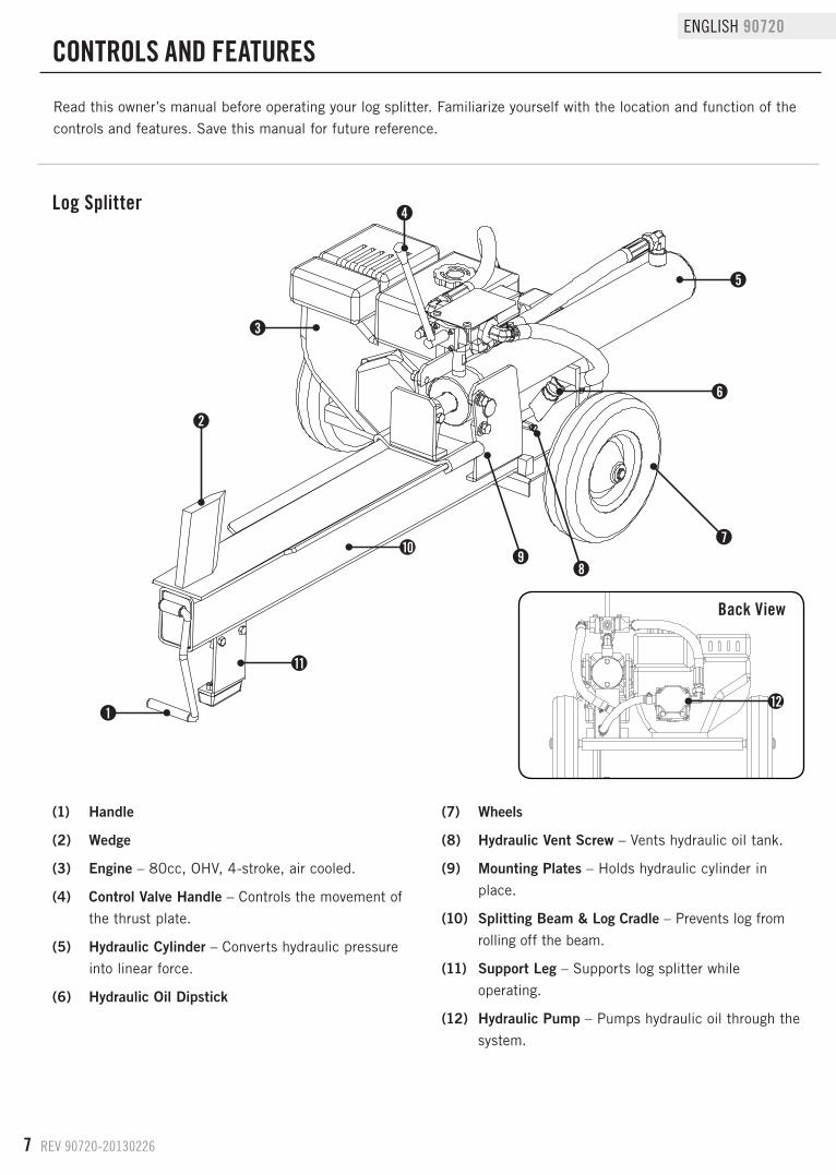
(1) Handle
(2) Wedge
(3) Engine – 80cc, OHV, 4-stroke, air cooled.
(4) Control Valve Handle – Controls the movement of
the thrust plate.
(5) Hydraulic Cylinder – Converts hydraulic pressure
into linear force.
(6) Hydraulic Oil Dipstick
(7) Wheels
(8) Hydraulic Vent Screw – Vents hydraulic oil tank.
(9) Mounting Plates – Holds hydraulic cylinder in
place.
(10) Splitting Beam & Log Cradle – Prevents log from
rolling off the beam.
(11) Support Leg – Supports log splitter while
operating.
(12) Hydraulic Pump – Pumps hydraulic oil through the
system.
Log Splitter
Back View
CONTROLS ANd FEATURES
Read this owner’s manual before operating your log splitter. Familiarize yourself with the location and function of the
controls and features. Save this manual for future reference.
2
4
1
3
10
11
12
6
5
79
8
REV 90720-20130226 8
90720 ENGLISH
ASSEMBLy
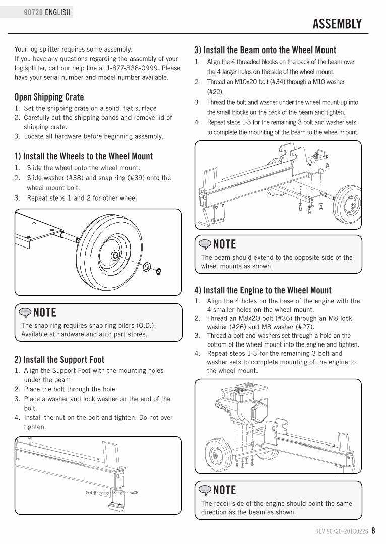
Your log splitter requires some assembly.If you have any questions regarding the assembly of your log splitter, call our help line at 1-877-338-0999. Please have your serial number and model number available.
Open Shipping Crate1. Set the shipping crate on a solid, flat surface2. Carefully cut the shipping bands and remove lid of
shipping crate.3. Locate all hardware before beginning assembly.
1) Install the Wheels to the Wheel Mount1. Slide the wheel onto the wheel mount.
2. Slide washer (#38) and snap ring (#39) onto the
wheel mount bolt.
3. Repeat steps 1 and 2 for other wheel
2) Install the Support Foot1. Align the Support Foot with the mounting holes
under the beam2. Place the bolt through the hole3. Place a washer and lock washer on the end of the
bolt.4. Install the nut on the bolt and tighten. Do not over
tighten.
3) Install the Beam onto the Wheel Mount1. Align the 4 threaded blocks on the back of the beam over
the 4 larger holes on the side of the wheel mount.
2. Thread an M10x20 bolt (#34) through a M10 washer
(#22).
3. Thread the bolt and washer under the wheel mount up into
the small blocks on the back of the beam and tighten.
4. Repeat steps 1-3 for the remaining 3 bolt and washer sets
to complete the mounting of the beam to the wheel mount.
4) Install the Engine to the Wheel Mount1. Align the 4 holes on the base of the engine with the
4 smaller holes on the wheel mount.2. Thread an M8x20 bolt (#36) through an M8 lock
washer (#26) and M8 washer (#27).3. Thread a bolt and washers set through a hole on the
bottom of the wheel mount into the engine and tighten.4. Repeat steps 1-3 for the remaining 3 bolt and
washer sets to complete mounting of the engine to the wheel mount.
The snap ring requires snap ring pilers (O.D.). Available at hardware and auto part stores.
NOTE
The beam should extend to the opposite side of the wheel mounts as shown.
NOTE
The recoil side of the engine should point the same direction as the beam as shown.
NOTE
9 REV 90720-20130226
ENGLISH 90720
ASSEMBLy
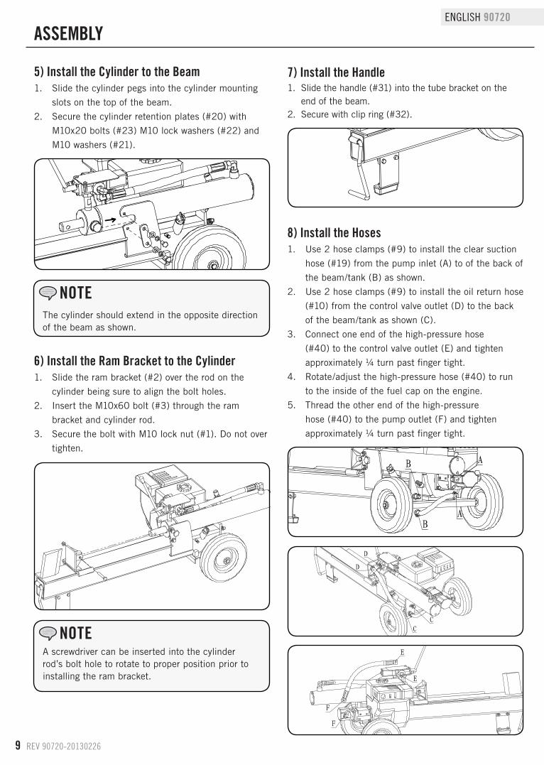
A screwdriver can be inserted into the cylinder rod’s bolt hole to rotate to proper position prior to installing the ram bracket.
NOTE
The cylinder should extend in the opposite direction of the beam as shown.
NOTE
6) Install the Ram Bracket to the Cylinder1. Slide the ram bracket (#2) over the rod on the
cylinder being sure to align the bolt holes.
2. Insert the M10x60 bolt (#3) through the ram
bracket and cylinder rod.
3. Secure the bolt with M10 lock nut (#1). Do not over
tighten.
7) Install the Handle1. Slide the handle (#31) into the tube bracket on the
end of the beam.2. Secure with clip ring (#32).
8) Install the Hoses1. Use 2 hose clamps (#9) to install the clear suction
hose (#19) from the pump inlet (A) to of the back of
the beam/tank (B) as shown.
2. Use 2 hose clamps (#9) to install the oil return hose
(#10) from the control valve outlet (D) to the back
of the beam/tank as shown (C).
3. Connect one end of the high-pressure hose
(#40) to the control valve outlet (E) and tighten
approximately ¼ turn past finger tight.
4. Rotate/adjust the high-pressure hose (#40) to run
to the inside of the fuel cap on the engine.
5. Thread the other end of the high-pressure
hose (#40) to the pump outlet (F) and tighten
approximately ¼ turn past finger tight.
A
A
B
B
CC
D
D
F
F
E
E
5) Install the Cylinder to the Beam1. Slide the cylinder pegs into the cylinder mounting
slots on the top of the beam.
2. Secure the cylinder retention plates (#20) with
M10x20 bolts (#23) M10 lock washers (#22) and
M10 washers (#21).
REV 90720-20130226 10
90720 ENGLISH
ASSEMBLy
Add Engine Oil
1. Make sure the log splitter is on a flat, level surface.
2. Remove oil fill cap/dipstick to add oil.
3. Add up to 0.42 qt (0.4 L) of oil. Replace oil fill cap/
dipstick. DO NOT OVERFILL.
4. Check engine oil level daily and add as needed.
DO NOT attempt to crank or start the engine before it has been properly filled with the recommended type and amount of oil. Damage to the log splitter as a result of failure to follow these instructions will void your warranty.
CAUTION
The engine is equipped with a low-oil-shutoff and will stop when the oil level in the crankcase falls below the threshold level.
CAUTION
Check oil often during the break-in period. Refer to the Maintenance section for recommended service intervals.
NOTE
Add Fuel Cont’d.
Our engines work well with 10% or less ethanol blend fuels. When using blended fuels there are some issues worth noting: – Ethanol-gasoline blends can absorb more water than
gasoline alone. – These blends can eventually separate, leaving water
or a watery goo in the tank, fuel valve and carburetor. – With gravity-fed fuel supplies, this compromised fuel
can be drawn into the carburetor and cause damage to the engine and/or potential hazards.
– There are only a few suppliers of fuel stabilizer that are formulated to work with ethanol blend fuels.
– Any damages or hazards caused by using improper fuel, improperly stored fuel, and/or improperly formulated stabilizers, are not covered by manufacture’s warranty.
It is advisable to always shut off the fuel supply, run the engine to fuel starvation and drain the tank when the equipment is not in use for more than 30 days.
NOTE
Add Fuel1. Use clean, fresh, regular unleaded fuel with a
minimum octane rating of 85 and an ethanol
content of less than 10% by volume.
2. DO NOT mix oil with fuel.
3. Clean the area around the fuel cap.
4. Remove the fuel cap.
Use regular unleaded gasoline with a minimum octane rating of 85.
Do not mix oil and gasoline.Fill tank to approximately ¼ in. (0.64 cm) below the top of the tank to allow for fuel expansion.DO NOT pump gas directly into the generator at the gas station. Use an approved container to transfer the fuel to the generator.DO NOT fill fuel tank indoors.DO NOT fill fuel tank when the engine is running or hot.DO NOT overfill the fuel tank.DO NOT light cigarettes or smoke when filling the fuel tank.
CAUTION
Pouring fuel too fast through the fuel screen may result in blow back of fuel at the operator while filling.
WARNING
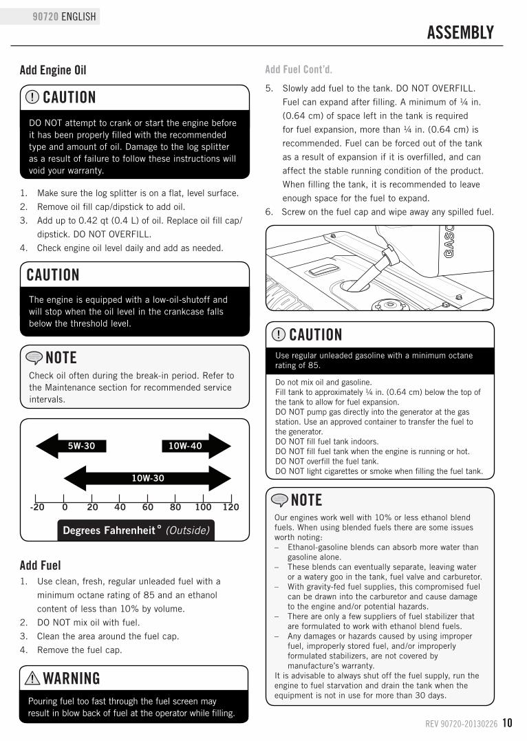
5. Slowly add fuel to the tank. DO NOT OVERFILL.
Fuel can expand after filling. A minimum of ¼ in.
(0.64 cm) of space left in the tank is required
for fuel expansion, more than ¼ in. (0.64 cm) is
recommended. Fuel can be forced out of the tank
as a result of expansion if it is overfilled, and can
affect the stable running condition of the product.
When filling the tank, it is recommended to leave
enough space for the fuel to expand.
6. Screw on the fuel cap and wipe away any spilled fuel.
11 REV 90720-20130226
ENGLISH 90720
ASSEMBLy
6. Replace and tighten the dipstick.7. Start engine (see Starting the Engine in the
Operation section).8. Extend and retract the cylinder to purge air from the
hydraulic system. Cylinder motion should be smooth and continuous.
9. Shut-off engine (see Stopping the Engine in the Operation section).
10. Check the hydraulic oil tank dipstick. Add additional hydraulic oil if needed.
11. Check oil level daily and add as needed.
When the outdoor tempurature is below 32 ˚F, Dexron III transmission fluid can be used.
NOTE
To check oil level, insert the dipstick into fill neck
until it stops. Remove and read level. Do not thread
dipstick into fill neck when checking oil.
NOTE
Always tighten the hydraulic vent screw when the engine is off and log splitter is not in use. When the vent screw is closed, it prevents dust, dirt, and debris from entering the tank. Closing the vent screw also prevents oil leakage when the log splitter is being transported.
NOTE
While the hydraulic vent screw is open, some hydraulic oil may spill out during transportation and/or operation especially if the log splitter is not on a level surface.
NOTE
Failure to open the hydraulic vent screw will cause pressure build-up due to heat. This creates difficulty during maintenance and operation.
NOTE
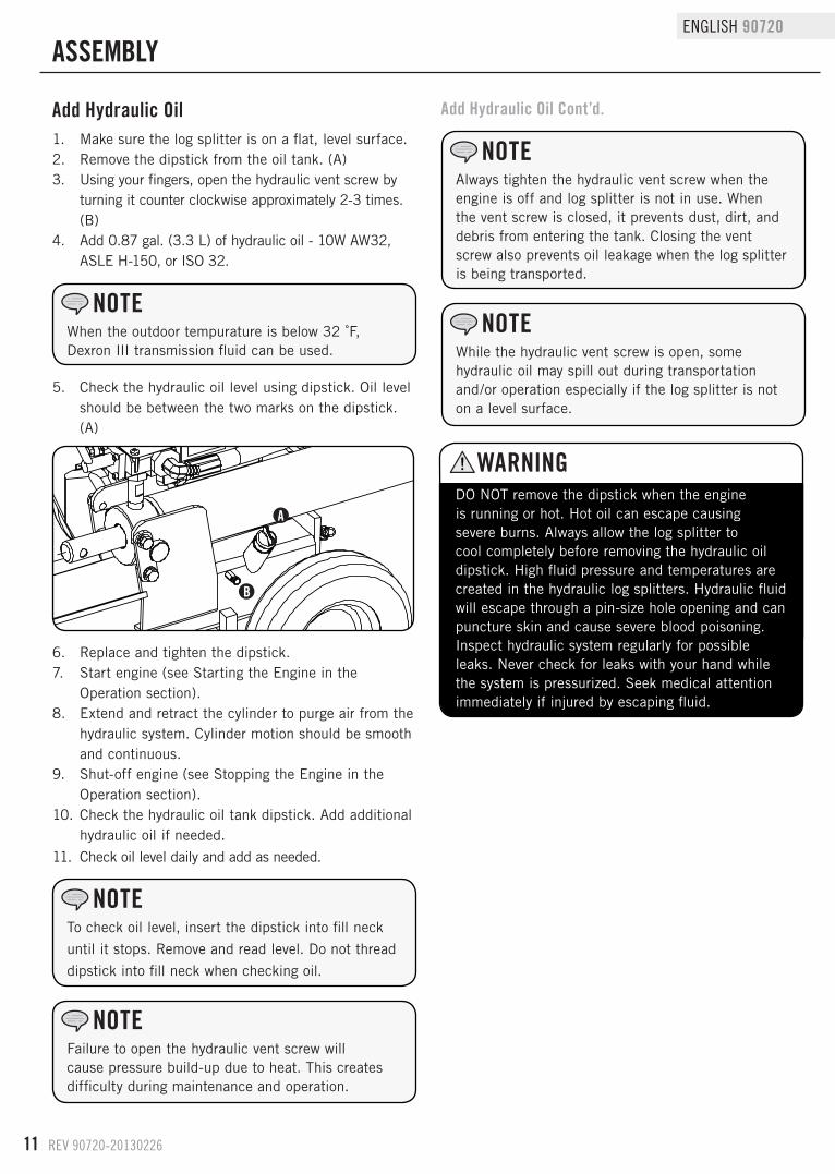
Add Hydraulic Oil1. Make sure the log splitter is on a flat, level surface.2. Remove the dipstick from the oil tank. (A)3. Using your fingers, open the hydraulic vent screw by
turning it counter clockwise approximately 2-3 times. (B)
4. Add 0.87 gal. (3.3 L) of hydraulic oil - 10W AW32, ASLE H-150, or ISO 32.
5. Check the hydraulic oil level using dipstick. Oil level should be between the two marks on the dipstick. (A)
DO NOT remove the dipstick when the engine is running or hot. Hot oil can escape causing severe burns. Always allow the log splitter to cool completely before removing the hydraulic oil dipstick. High fluid pressure and temperatures are created in the hydraulic log splitters. Hydraulic fluid will escape through a pin-size hole opening and can puncture skin and cause severe blood poisoning. Inspect hydraulic system regularly for possible leaks. Never check for leaks with your hand while the system is pressurized. Seek medical attention immediately if injured by escaping fluid.
WARNING
A
B
Add Hydraulic Oil Cont’d.
REV 90720-20130226 12
90720 ENGLISH
OPERATION
Before Each Use Inspect the Log Splitter1. Check the hydraulic oil level and visually inspect all
hoses, attachments and cylinder for loose fittings, leaks, cracks, fraying or other damage.
2. DO NOT operate the log splitter if there is any indication of damage.
3. Inspect the engine and make sure the oil level is correct before operating. If the engine is equipped with a spark arrestor, clean and inspect it regularly (follow spark arrestor maintenance schedule).
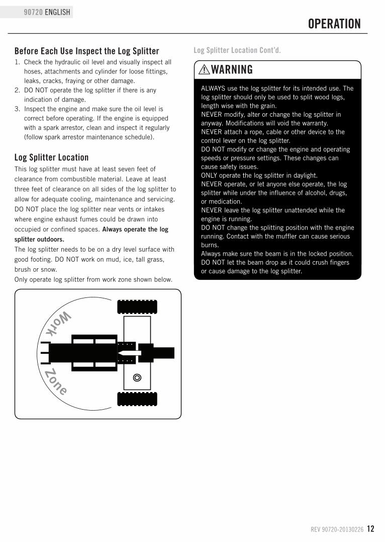
Work Zone
Log Splitter LocationThis log splitter must have at least seven feet of
clearance from combustible material. Leave at least
three feet of clearance on all sides of the log splitter to
allow for adequate cooling, maintenance and servicing.
DO NOT place the log splitter near vents or intakes
where engine exhaust fumes could be drawn into
occupied or confined spaces. Always operate the log splitter outdoors.The log splitter needs to be on a dry level surface with
good footing. DO NOT work on mud, ice, tall grass,
brush or snow.
Only operate log splitter from work zone shown below.
ALWAYS use the log splitter for its intended use. The log splitter should only be used to split wood logs, length wise with the grain. NEVER modify, alter or change the log splitter in anyway. Modifications will void the warranty. NEVER attach a rope, cable or other device to the control lever on the log splitter. DO NOT modify or change the engine and operating speeds or pressure settings. These changes can cause safety issues. ONLY operate the log splitter in daylight. NEVER operate, or let anyone else operate, the log splitter while under the influence of alcohol, drugs, or medication. NEVER leave the log splitter unattended while the engine is running. DO NOT change the splitting position with the engine running. Contact with the muffler can cause serious burns. Always make sure the beam is in the locked position. DO NOT let the beam drop as it could crush fingers or cause damage to the log splitter.
WARNING
Log Splitter Location Cont’d.
13 REV 90720-20130226
ENGLISH 90720
OPERATION
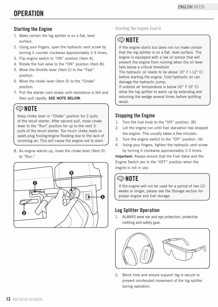
Starting the Engine Cont’d.Starting the Engine1. Make certain the log splitter is on a flat, level
surface.
2. Using your fingers, open the hydraulic vent screw by
turning it counter clockwise approximately 2-3 times.
3. Flip engine switch to “ON” position (Item A).
4. Rotate the fuel valve to the “ON” position (Item B).
5. Move the throttle lever (Item C) to the “Fast”
position.
6. Move the choke lever (Item D) to the “Choke”
position.
7. Pull the starter cord slowly until resistance is felt and
then pull rapidly. SEE NOTE BELOW.
8. As engine warms up, move the choke lever (Item D)
to “Run.”
If the engine starts but does not run make certain that the log splitter is on a flat, level surface. The engine is equipped with a low oil sensor that will prevent the engine from running when the oil level falls below a critical threshold.The hydraulic oil needs to be above 10° F (-12° C) before starting the engine. Cold hydraulic oil can damage the hydraulic pump.If outdoor air temperature is below 32° F (0° C) allow the log splitter to warm up by extending and returning the wedge several times before splitting wood.
NOTE
A
B
C
d
Keep choke lever in “Choke” position for 2 pulls of the recoil starter. After second pull, move choke lever to the “Run” position for up to the next 3 pulls of the recoil starter. Too much choke leads to spark plug fouling/engine flooding due to the lack of incoming air. This will cause the engine not to start.
NOTEStopping the Engine1. Turn the fuel knob to the “Off” position. (B)
2. Let the engine run until fuel starvation has stopped
the engine. This usually takes a few minutes.
3. Turn the engine switch to the “Off” position. (A)
4. Using your fingers, tighten the hydraulic vent screw
by turning it clockwise approximately 2-3 times.
Important: Always ensure that the Fuel Valve and the
Engine Switch are in the “OFF” position when the
engine is not in use.
If the engine will not be used for a period of two (2) weeks or longer, please see the Storage section for proper engine and fuel storage.
NOTE
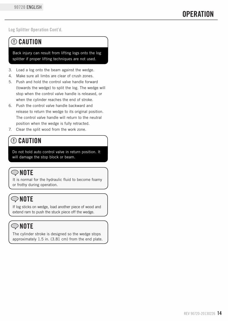
Log Splitter Operation1. ALWAYS wear ear and eye protection, protective
clothing and safety gear.
2. Block tires and ensure support leg is secure to
prevent unintended movement of the log splitter
during operation.
REV 90720-20130226 14
90720 ENGLISH
Log Splitter Operation Cont’d.
OPERATION
Back injury can result from lifting logs onto the log
splitter if proper lifting techniques are not used.
CAUTION
It is normal for the hydraulic fluid to become foamy or frothy during operation.
NOTE
If log sticks on wedge, load another piece of wood and extend ram to push the stuck piece off the wedge.
NOTE
Do not hold auto control valve in return position. It will damage the stop block or beam.
CAUTION
The cylinder stroke is designed so the wedge stops approximately 1.5 in. (3.81 cm) from the end plate.
NOTE
3. Load a log onto the beam against the wedge.
4. Make sure all limbs are clear of crush zones.
5. Push and hold the control valve handle forward
(towards the wedge) to split the log. The wedge will
stop when the control valve handle is released, or
when the cylinder reaches the end of stroke.
6. Push the control valve handle backward and
release to return the wedge to its original position.
The control valve handle will return to the neutral
position when the wedge is fully retracted.
7. Clear the split wood from the work zone.
15 REV 90720-20130226
ENGLISH 90720
MAINTENANCE ANd STORAGE
The owner/operator is responsible for all periodic maintenance.
Complete all scheduled maintenance in a timely manner. Correct any issue before operating the log splitter.
For service or parts assistance, contact our help line at 1-877-338-0999.
NOTE
Never operate a damaged or defective log splitter.
WARNING
Improper maintenance will void your warranty.
WARNING
Engine MaintenanceTo prevent accidental starting, remove and ground spark
plug wire before performing any service.
OilChange oil when the engine is warm. Refer to the oil
specification to select the proper grade of oil for your
operating environment.
1. Remove the oil drain plug with a 12 mm socket and
extension.
2. Allow the oil to drain completely.
3. Replace the drain plug.
4. Remove oil fill cap/dipstick to add oil.
5. Add up to 0.42 qt. (0.4 L) of oil and replace oil fill
cap/dipstick. DO NOT OVERFILL.
6. Dispose of used oil at an approved waste
management facility.
Spark Plugs1. Remove the spark plug cable from the spark plug.
2. Inspect the electrode on the plug. It must be clean
and not worn to produce the spark required for
ignition.
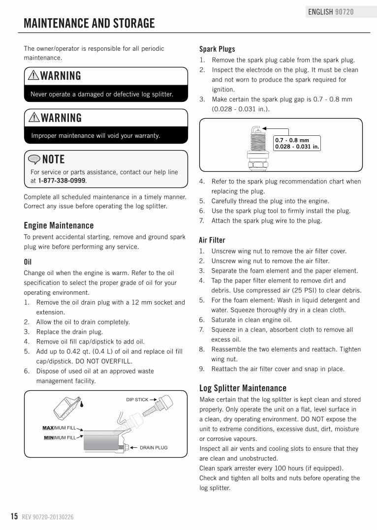
3. Make certain the spark plug gap is 0.7 - 0.8 mm
(0.028 - 0.031 in.).
Log Splitter MaintenanceMake certain that the log splitter is kept clean and stored
properly. Only operate the unit on a flat, level surface in
a clean, dry operating environment. DO NOT expose the
unit to extreme conditions, excessive dust, dirt, moisture
or corrosive vapours.
Inspect all air vents and cooling slots to ensure that they
are clean and unobstructed.
Clean spark arrester every 100 hours (if equipped).
Check and tighten all bolts and nuts before operating the
log splitter.
Air Filter1. Unscrew wing nut to remove the air filter cover.
2. Unscrew wing nut to remove the air filter.
3. Separate the foam element and the paper element.
4. Tap the paper filter element to remove dirt and
debris. Use compressed air (25 PSI) to clear debris.
5. For the foam element: Wash in liquid detergent and
water. Squeeze thoroughly dry in a clean cloth.
6. Saturate in clean engine oil.
7. Squeeze in a clean, absorbent cloth to remove all
excess oil.
8. Reassemble the two elements and reattach. Tighten
wing nut.
9. Reattach the air filter cover and snap in place.
0.7 - 0.8 mm0.028 - 0.031 in.
4. Refer to the spark plug recommendation chart when
replacing the plug.
5. Carefully thread the plug into the engine.
6. Use the spark plug tool to firmly install the plug.
7. Attach the spark plug wire to the plug.
REV 90720-20130226 16
90720 ENGLISH
MAINTENANCE ANd STORAGE
Maintenance ScheduleFollow the service intervals indicated in the schedule
below. Service your log splitter more frequently when
operating in adverse conditions. Contact our help line at
1-877-338-0999 to locate the nearest Champion Power
Equipment authorized service dealer for your log splitter
or engine maintenance needs.
*To be performed by knowledgeable, experienced owners or Champion Power Equipment certified dealers.
Every 8 hours or daily
Check engine and hydraulic oil levels
Clean around air intake and muffler
First 5 Hours
Change engine oil
Every 50 hours or every season
Clean air filter
Change engine oil if operating under heavy load or in hot environments
Every 100 hours or every season
Change engine oil
Clean/Adjust spark plug
Check/Adjust valve clearance*
Clean fuel tank and filter*
Change hydraulic oil
Every year
Inspect wheel bearings and repack bearing grease as needed.
Every 3 years
Replace fuel line
DO NOT use a garden hose to clean the engine or log splitter.
CAUTION
Water can contaminate the fuel system and can enter the engine through the cooling slots and damage the engine.
Cleaning
Clear the debris from the beam, wedge and endplate. Use a damp cloth to clean exterior surfaces of the engine and log splitter.Use a soft bristle brush to remove excess dirt and oil. Use an air compressor (25 PSI) to clear dirt and small debris.Wipe all metal parts with an oily rag to help prevent rust and corrosion.
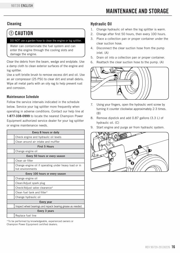
Hydraulic Oil1. Change hydraulic oil when the log splitter is warm.
2. Change after first 50 hours, then every 100 hours.
3. Place a collection pan or proper container under the
clear suction hose.
4. Disconnect the clear suction hose from the pump
inlet. (A)
5. Drain oil into a collection pan or proper container.
6. Reattach the clear suction hose to the pump. (A)
A7. Using your fingers, open the hydraulic vent screw by
turning it counter clockwise approximately 2-3 times. (B)
8. Remove dipstick and add 0.87 gallons (3.3 L) of
hydraulic oil. (C)
9. Start engine and purge air from hydraulic system.
C
B
17 REV 90720-20130226
ENGLISH 90720
Never store the log splitter inside next to appliances where there is a source of heat or open flame, spark or pilot light because they can ignite gasoline vapors. DO NOT store a log splitter near fertilizer or any corrosive material. Even with an empty gas tank, gasoline vapors could ignite.
WARNING
StorageRefer to the Maintenance section for proper cleaning
instructions.
Log Splitter Storage1. The log splitter needs to be cool for at least 5
minutes before storing.
2. Clean the log splitter before storage according to the
Maintenance section.
3. Retract the wedge to protect the rod from corrosion.
4. Wipe the beam and wedge with an oily rag to
prevent rust and corrosion.
Engine Stored for Less than 30 days1. Allow the engine to cool completely before storage.
2. Clean engine according to the Maintenance section.
3. To extend the fuel storage life add a properly
formulated fuel stabilizer to the tank.
4. Ensure the fuel valve is in the “OFF” position.
Engines Stored for Over 30 days1. Add a properly formulated fuel stabilizer to the tank.
2. Run the engine for a few minutes so the treated fuel
cycles through the fuel system and carburetor.
3. Turn the fuel valve to the “Off” position.
4. Let the engine run until fuel starvation has stopped
the engine. This usually takes a few minutes.
5. The engine needs to cool completely before cleaning
and storage.
6. Clean the engine according to the maintenance section.
7. Change the oil.
8. Remove the spark plug and pour about 1⁄2 ounce
of oil into the cylinder. Using the Recoil, crank the
engine slowly to distribute the oil and lubricate the
cylinder.
9. Reattach the spark plug.
MAINTENANCE ANd STORAGE
Engine exhaust contains odorless and colorless carbon monoxide gas.
To avoid accidental or unintended ignition of your engine during periods of storage, the following precautions should be followed:
– When storing the engine for short or extended periods of time make sure that the Engine
Switch and the Fuel Valve are set in the OFF
position.
dANGER
Generator Storage Cont’d.
REV 90720-20130226 18
90720 ENGLISH
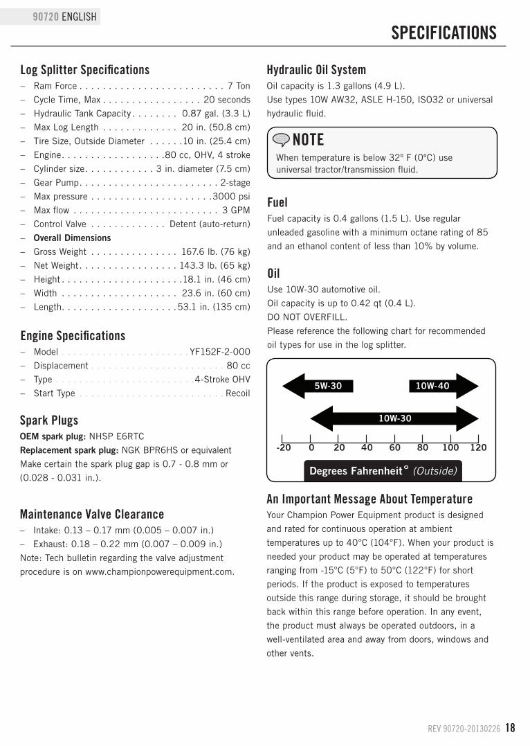
Log Splitter Specifications – Ram Force . . . . . . . . . . . . . . . . . . . . . . . . . 7 Ton
– Cycle Time, Max . . . . . . . . . . . . . . . . . 20 seconds
– Hydraulic Tank Capacity . . . . . . . . 0.87 gal. (3.3 L)
– Max Log Length . . . . . . . . . . . . . 20 in. (50.8 cm)
– Tire Size, Outside Diameter . . . . . .10 in. (25.4 cm)
– Engine . . . . . . . . . . . . . . . . . .80 cc, OHV, 4 stroke
– Cylinder size . . . . . . . . . . . . 3 in. diameter (7.5 cm)
– Gear Pump . . . . . . . . . . . . . . . . . . . . . . . . 2-stage
– Max pressure . . . . . . . . . . . . . . . . . . . . .3000 psi
– Max flow . . . . . . . . . . . . . . . . . . . . . . . . . 3 GPM
– Control Valve . . . . . . . . . . . . . Detent (auto-return)
– Overall Dimensions – Gross Weight . . . . . . . . . . . . . . . 167.6 lb. (76 kg)
– Net Weight . . . . . . . . . . . . . . . . . 143.3 lb. (65 kg)
– Height . . . . . . . . . . . . . . . . . . . . .18.1 in. (46 cm)
– Width . . . . . . . . . . . . . . . . . . . . 23.6 in. (60 cm)
– Length. . . . . . . . . . . . . . . . . . . .53.1 in. (135 cm)
SPECIFICATIONS
Engine Specifications – Model . . . . . . . . . . . . . . . . . . . . . . YF152F-2-000
– Displacement . . . . . . . . . . . . . . . . . . . . . . . 80 cc
– Type . . . . . . . . . . . . . . . . . . . . . . . .4-Stroke OHV
– Start Type . . . . . . . . . . . . . . . . . . . . . . . . . Recoil
Hydraulic Oil SystemOil capacity is 1.3 gallons (4.9 L).
Use types 10W AW32, ASLE H-150, ISO32 or universal
hydraulic fluid.
When temperature is below 32º F (0ºC) use universal tractor/transmission fluid.
NOTE
Maintenance Valve Clearance – Intake: 0.13 – 0.17 mm (0.005 – 0.007 in.)
– Exhaust: 0.18 – 0.22 mm (0.007 – 0.009 in.)
Note: Tech bulletin regarding the valve adjustment
procedure is on www.championpowerequipment.com.
Spark PlugsOEM spark plug: NHSP E6RTC
Replacement spark plug: NGK BPR6HS or equivalent
Make certain the spark plug gap is 0.7 - 0.8 mm or
(0.028 - 0.031 in.).
OilUse 10W-30 automotive oil.
Oil capacity is up to 0.42 qt (0.4 L).
DO NOT OVERFILL.
Please reference the following chart for recommended
oil types for use in the log splitter.
FuelFuel capacity is 0.4 gallons (1.5 L). Use regular
unleaded gasoline with a minimum octane rating of 85
and an ethanol content of less than 10% by volume.
An Important Message About TemperatureYour Champion Power Equipment product is designed
and rated for continuous operation at ambient
temperatures up to 40°C (104°F). When your product is
needed your product may be operated at temperatures
ranging from -15°C (5°F) to 50°C (122°F) for short
periods. If the product is exposed to temperatures
outside this range during storage, it should be brought
back within this range before operation. In any event,
the product must always be operated outdoors, in a
well-ventilated area and away from doors, windows and
other vents.
19 REV 90720-20130226
ENGLISH 90720
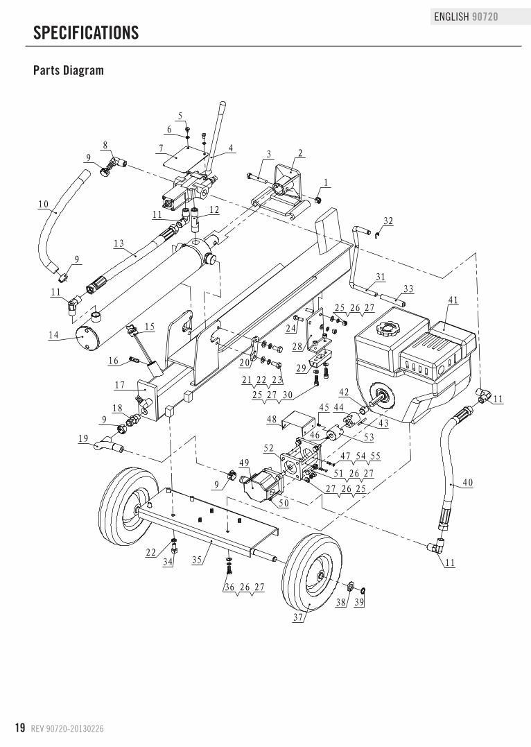
Parts diagram
SPECIFICATIONS
23
1
4
5
6
789
1011 12
13
11
9
1415
16
17
189
19
3422
35
37
38 39
11
9
49
50
27 26 25
51 26 27
25 26 27
302725
3331
32
41
40
11
43
42
44
53
45
46
36 26 27
20
232221
24
29
48
52
28
47 54 55
序号
代 号 名 称
默认/数量
材 料 重 量 备 注
1 GB/T 889.1-20001型非金属嵌件六角锁紧
螺母 M101 钢
2 PMJ7-02 推木架 1 焊接件 2.22
3 GB/T 5782-2000 六角头螺栓 M10×60 1 钢
4 PMJ7-21 控制阀 1 Q235 3.59
5 GB/T 818-2000 十字槽盘头螺钉 M6×10 2 35 0.01
6 GB/T 859-1987 轻型弹簧垫圈 6 2 65Mn 0.00
7 PMJ7-23 标贴板 1 Q235 0.13
8 PMJ7-16 直角回油接头 1 35 0.12
9 JB/T 8870-1999 喉箍 d25 4 示意图 0.00
10 PMJ7-26 回油管 1 0.08
11 PMJ7-15 直角接头 4 35 0.13
12 PMJ7-22 直通接头 1 45 0.15
13 PMJ7-25 油缸油管 1 0.51
14 PMJ7-08 油缸总成 1 装配件 13.43
15 PMJ7-05 油塞 1 尼龙66 0.01
16 PMJ7-24 通气阀 1 组合件 0.01
17 PMJ7-01 工作架 1 焊接件 22.96
18 PMJ7-18 吸油管接头 1 45 0.06
19 PMJ7-19 吸油管 1 示意图 0.08
20 PMJ15-05 锁紧块 2 Q235 0.08
21 GB/T 95-2000 C级平垫圈 10 4
22 GB/T 93-1987 标准型弹簧垫圈 10 8 65Mn
23 GB/T 5781-2000C级全螺纹六角头螺栓
M10×204 35 0.02
24 GB/T 5780-2000 C级六角头螺栓 M8×25 2
25 GB/T 41-2000 C级六角螺母 M8 8
26 GB/T 93-1987 标准型弹簧垫圈 8 14 65Mn 0.00
27 GB/T 95-2000 C级平垫圈 8 16
28 PMJ7-04 前支撑板 1 Q235 0.44
29 PMJ7-07 减震垫 1 橡胶Ⅰ- 3 0.05
30 GB/T 70.1-2000内六角圆柱头螺钉
M8×252 钢
31 PMJ7-06 提手 1 Q235 0.31
32 GB/T 896-86 开口挡圈 9 1 65Mn 0.00
33 PMJ7-20 提手套 1 耐油橡胶Ⅰ- 2 0.01
34 GB/T 70.1-2000内六角圆柱头螺钉
M10×204
35 PMJ7-03 轮架组件 1 焊接件 3.07
36 GB/T 5783-2000全螺纹六角头螺栓
M8×204
37 PMJ7-10 橡胶夹板轮 2 橡胶Ⅰ- 2 3.80
38 GB/T 95-2000 C级平垫圈 16 2
39 GB/T 894.1-1986 A型轴用弹性挡圈 16 2 65Mn 0.00
40 PMJ7-11 输入油管 1 组合件 0.53
41 PMJ7-09 80CC发动机 1 示意图 0.01
42 PMJ7-12 间隔套 1 Q235 0.02
43 PMJ7-13 方键 1 45 0.01
44 PMJ7-14 发动机联轴器 1 铁基粉末冶金 0.23
45 GB/T 77-2000内六角平端紧定螺钉
M6×101
46 GB/T 1099-1979 半圆键 3×5×13 1
47 GB/T 845F-1985F型十字槽盘头自攻螺钉
T4.2×104
48 PMJ22G-32 连接套筒盖 1 Q235 0.11
49 PMJ7-17 双联齿轮泵 1 示意图 0.00
50 GB/T 5783-2000全螺纹六角头螺栓
M8×304
51 ASME B18.2.1 1996全螺纹六角头螺栓 5/16"-24×1"
4
52 PMJ22G-27 连接套筒 1 ZL101A 0.46
53 PMJ22G-26 泵联轴器 1 铁基粉末冶金 0.24
54 GB/T 848-1985 A级小垫圈 4 4 材质 <未指定> 0.02
55 GB/T 859-1987 轻型弹簧垫圈 4 4
REV 90720-20130226 20
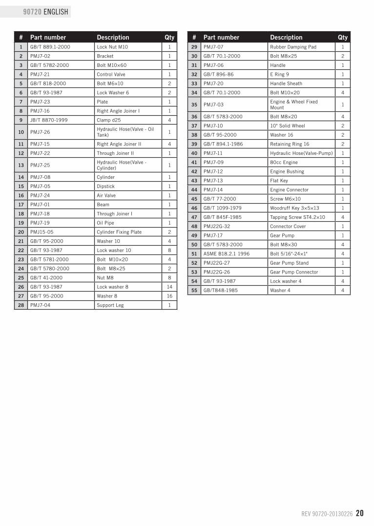
90720 ENGLISH Parts List
# Part number Description Qty1 GB/T 889.1-2000 Lock Nut M10 1
2 PMJ7-02 Bracket 1
3 GB/T 5782-2000 Bolt M10×60 1
4 PMJ7-21 Control Valve 1
5 GB/T 818-2000 Bolt M6×10 2
6 GB/T 93-1987 Lock Washer 6 2
7 PMJ7-23 Plate 1
8 PMJ7-16 Right Angle Joiner I 1
9 JB/T 8870-1999 Clamp d25 4
10 PMJ7-26Hydraulic Hose(Valve - Oil Tank)
1
11 PMJ7-15 Right Angle Joiner II 4
12 PMJ7-22 Through Joiner II 1
13 PMJ7-25Hydraulic Hose(Valve - Cylinder)
1
14 PMJ7-08 Cylinder 1
15 PMJ7-05 Dipstick 1
16 PMJ7-24 Air Valve 1
17 PMJ7-01 Beam 1
18 PMJ7-18 Through Joiner I 1
19 PMJ7-19 Oil Pipe 1
20 PMJ15-05 Cylinder Fixing Plate 2
21 GB/T 95-2000 Washer 10 4
22 GB/T 93-1987 Lock washer 10 8
23 GB/T 5781-2000 Bolt M10×20 4
24 GB/T 5780-2000 Bolt M8×25 2
25 GB/T 41-2000 Nut M8 8
26 GB/T 93-1987 Lock washer 8 14
27 GB/T 95-2000 Washer 8 16
28 PMJ7-04 Support Leg 1
# Part number Description Qty29 PMJ7-07 Rubber Damping Pad 1
30 GB/T 70.1-2000 Bolt M8×25 2
31 PMJ7-06 Handle 1
32 GB/T 896-86 E Ring 9 1
33 PMJ7-20 Handle Sheath 1
34 GB/T 70.1-2000 Bolt M10×20 4
35 PMJ7-03Engine & Wheel Fixed Mount
1
36 GB/T 5783-2000 Bolt M8×20 4
37 PMJ7-10 10" Solid Wheel 2
38 GB/T 95-2000 Washer 16 2
39 GB/T 894.1-1986 Retaining Ring 16 2
40 PMJ7-11 Hydraulic Hose(Valve-Pump) 1
41 PMJ7-09 80cc Engine 1
42 PMJ7-12 Engine Bushing 1
43 PMJ7-13 Flat Key 1
44 PMJ7-14 Engine Connector 1
45 GB/T 77-2000 Screw M6×10 1
46 GB/T 1099-1979 Woodruff Key 3×5×13 1
47 GB/T 845F-1985 Tapping Screw ST4.2×10 4
48 PMJ22G-32 Connector Cover 1
49 PMJ7-17 Gear Pump 1
50 GB/T 5783-2000 Bolt M8×30 4
51 ASME B18.2.1 1996 Bolt 5/16"-24×1" 4
52 PMJ22G-27 Gear Pump Stand 1
53 PMJ22G-26 Gear Pump Connector 1
54 GB/T 93-1987 Lock washer 4 4
55 GB/T848-1985 Washer 4 4
21 REV 90720-20130226
ENGLISH 90720
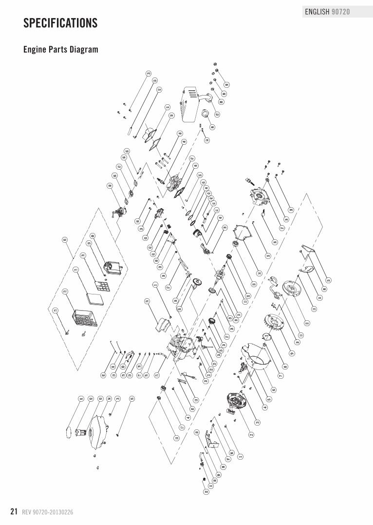
Engine Parts diagram
SPECIFICATIONS
1
2
3
45
6
78
9
1011
12
13
14
15
16
17
18
2021
2223
2425
2627
2829 30
31
32
33
34
35
36
37
38
3940
41
4243
4445
4647
4849
5051
5253
54
5556
5758
59
6162
63
64
6566
67
68
74
75767778
798081
82
16
13
41
35
60
66
24
1
1919
83
6919
70
71
72
73
84
3
4
85
8687
8889
90
91 92 94 95
9697
9899
100101
102
93 3
103
REV 90720-20130226 22
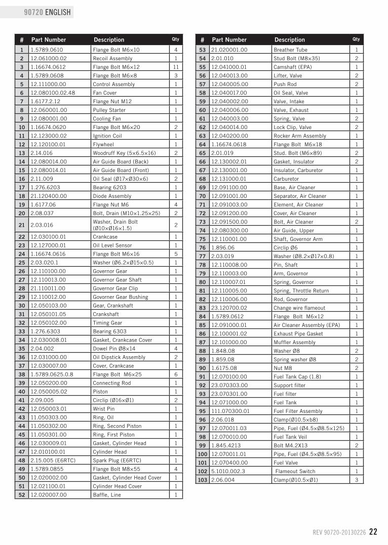
90720 ENGLISH Engine Parts List
# Part Number Description Qty
1 1.5789.0610 Flange Bolt M6×10 4
2 12.061000.02 Recoil Assembly 1
3 1.16674.0612 Flange Bolt M6×12 11
4 1.5789.0608 Flange Bolt M6×8 3
5 12.111000.00 Control Assembly 1
6 12.080100.02.48 Fan Cover 1
7 1.6177.2.12 Flange Nut M12 1
8 12.060001.00 Pulley Starter 1
9 12.080001.00 Cooling Fan 1
10 1.16674.0620 Flange Bolt M6×20 2
11 12.123000.02 Ignition Coil 1
12 12.120100.01 Flywheel 1
13 2.14.016 Woodruff Key (5×6.5×16) 2
14 12.080014.00 Air Guide Board (Back) 1
15 12.080014.01 Air Guide Board (Front) 1
16 2.11.009 Oil Seal (Ø17×Ø30×6) 2
17 1.276.6203 Bearing 6203 1
18 21.120400.00 Diode Assembly 1
19 1.6177.06 Flange Nut M6 4
20 2.08.037 Bolt, Drain (M10×1.25×25) 2
21 2.03.016Washer, Drain Bolt (Ø10×Ø16×1.5)
2
22 12.030100.01 Crankcase 1
23 12.127000.01 Oil Level Sensor 1
24 1.16674.0616 Flange Bolt M6×16 5
25 2.03.020.1 Washer (Ø6.2×Ø15×0.5) 1
26 12.110100.00 Governor Gear 1
27 12.110013.00 Governor Gear Shaft 1
28 21.110011.00 Governor Gear Clip 1
29 12.110012.00 Govorner Gear Bushing 1
30 12.050103.00 Gear, Crankshaft 1
31 12.050101.05 Crankshaft 1
32 12.050102.00 Timing Gear 1
33 1.276.6303 Bearing 6303 1
34 12.030008.01 Gasket, Crankcase Cover 1
35 2.04.002 Dowel Pin Ø8×14 4
36 12.031000.00 Oil Dipstick Assembly 2
37 12.030007.00 Cover, Crankcase 1
38 1.5789.0625.0.8 Flange Bolt M6×25 6
39 12.050200.00 Connecting Rod 1
40 12.050005.02 Piston 1
41 2.09.005 Circlip (Ø16×Ø1) 2
42 12.050003.01 Wrist Pin 1
43 11.050303.00 Ring, Oil 1
44 11.050302.00 Ring, Second Piston 1
45 11.050301.00 Ring, First Piston 1
46 12.030009.01 Gasket, Cylinder Head 1
47 12.010100.01 Cylinder Head 1
48 2.15.005 (E6RTC) Spark Plug (E6RTC) 1
49 1.5789.0855 Flange Bolt M8×55 4
50 12.020002.00 Gasket, Cylinder Head Cover 1
51 12.021100.01 Cylinder Head Cover 1
52 12.020007.00 Baffle, Line 1
# Part Number Description Qty
53 21.020001.00 Breather Tube 1
54 2.01.010 Stud Bolt (M8×35) 2
55 12.041000.01 Camshaft (EPA) 1
56 12.040013.00 Lifter, Valve 2
57 12.040005.00 Push Rod 2
58 12.040017.00 Oil Seal, Valve 1
59 12.040002.00 Valve, Intake 1
60 12.040006.00 Valve, Exhaust 1
61 12.040003.00 Spring, Valve 2
62 12.040014.00 Lock Clip, Valve 2
63 12.040200.00 Rocker Arm Assembly 1
64 1.16674.0618 Flange Bolt M6×18 1
65 2.01.019 Stud. Bolt (M6×89) 2
66 12.130002.01 Gasket, Insulator 2
67 12.130001.00 Insulator, Carburetor 1
68 12.131000.01 Carburetor 1
69 12.091100.00 Base, Air Cleaner 1
70 12.091001.00 Separator, Air Cleaner 1
71 12.091003.00 Element, Air Cleaner 1
72 12.091200.00 Cover, Air Cleaner 1
73 12.091500.00 Bolt, Air Cleaner 2
74 12.080300.00 Air Guide, Upper 1
75 12.110001.00 Shaft, Governor Arm 1
76 1.896.06 Circlip Ø6 1
77 2.03.019 Washer (Ø8.2×Ø17×0.8) 1
78 12.110008.00 Pin, Shaft 1
79 12.110003.00 Arm, Governor 1
80 12.110007.01 Spring, Governor 1
81 12.110005.00 Spring, Throttle Return 1
82 12.110006.00 Rod, Governor 1
83 23.120700.02 Change wire flameout 1
84 1.5789.0612 Flange Bolt M6×12 1
85 12.091000.01 Air Cleaner Assembly (EPA) 1
86 12.100001.02 Exhaust Pipe Gasket 1
87 12.101000.00 Muffler Assembly 1
88 1.848.08 Washer Ø8 2
89 1.859.08 Spring washer Ø8 2
90 1.6175.08 Nut M8 2
91 12.070100.00 Fuel Tank Cap (1.8) 1
92 23.070303.00 Support filter 1
93 23.070301.00 Fuel filter 1
94 12.071000.00 Fuel Tank 1
95 111.070300.01 Fuel Filter Assembly 1
96 2.06.018 Clamp(Ø10.5×b8) 1
97 12.070011.03 Pipe, Fuel (Ø4.5×Ø8.5×125) 1
98 12.070010.00 Fuel Tank Veil 1
99 1.845.4213 Bolt M4.2X13 2
100 12.070011.01 Pipe, Fuel (Ø4.5×Ø8.5×95) 1
101 12.070400.00 Fuel Valve 1
102 5.1010.002.3 Flameout Switch 1
103 2.06.004 Clamp(Ø10.5×Ø1) 3
23 REV 90720-20130226
ENGLISH 90720
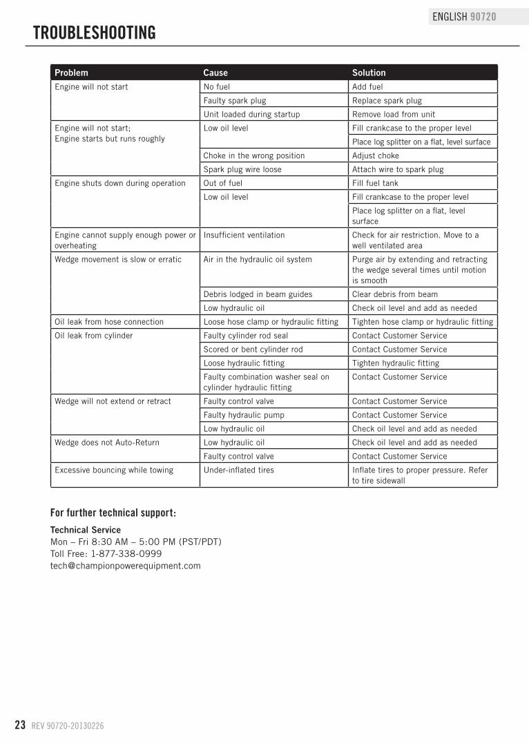
TROUBLESHOOTING
For further technical support:
Technical ServiceMon – Fri 8:30 AM – 5:00 PM (PST/PDT)Toll Free: [email protected]
Problem Cause SolutionEngine will not start No fuel Add fuel
Faulty spark plug Replace spark plug
Unit loaded during startup Remove load from unit
Engine will not start;Engine starts but runs roughly
Low oil level Fill crankcase to the proper level
Place log splitter on a flat, level surface
Choke in the wrong position Adjust choke
Spark plug wire loose Attach wire to spark plug
Engine shuts down during operation Out of fuel Fill fuel tank
Low oil level Fill crankcase to the proper level
Place log splitter on a flat, level surface
Engine cannot supply enough power or overheating
Insufficient ventilation Check for air restriction. Move to a well ventilated area
Wedge movement is slow or erratic Air in the hydraulic oil system Purge air by extending and retracting the wedge several times until motion is smooth
Debris lodged in beam guides Clear debris from beam
Low hydraulic oil Check oil level and add as needed
Oil leak from hose connection Loose hose clamp or hydraulic fitting Tighten hose clamp or hydraulic fitting
Oil leak from cylinder Faulty cylinder rod seal Contact Customer Service
Scored or bent cylinder rod Contact Customer Service
Loose hydraulic fitting Tighten hydraulic fitting
Faulty combination washer seal on cylinder hydraulic fitting
Contact Customer Service
Wedge will not extend or retract Faulty control valve Contact Customer Service
Faulty hydraulic pump Contact Customer Service
Low hydraulic oil Check oil level and add as needed
Wedge does not Auto-Return Low hydraulic oil Check oil level and add as needed
Faulty control valve Contact Customer Service
Excessive bouncing while towing Under-inflated tires Inflate tires to proper pressure. Refer to tire sidewall
REV 90720-20130226 24
90720 ENGLISH
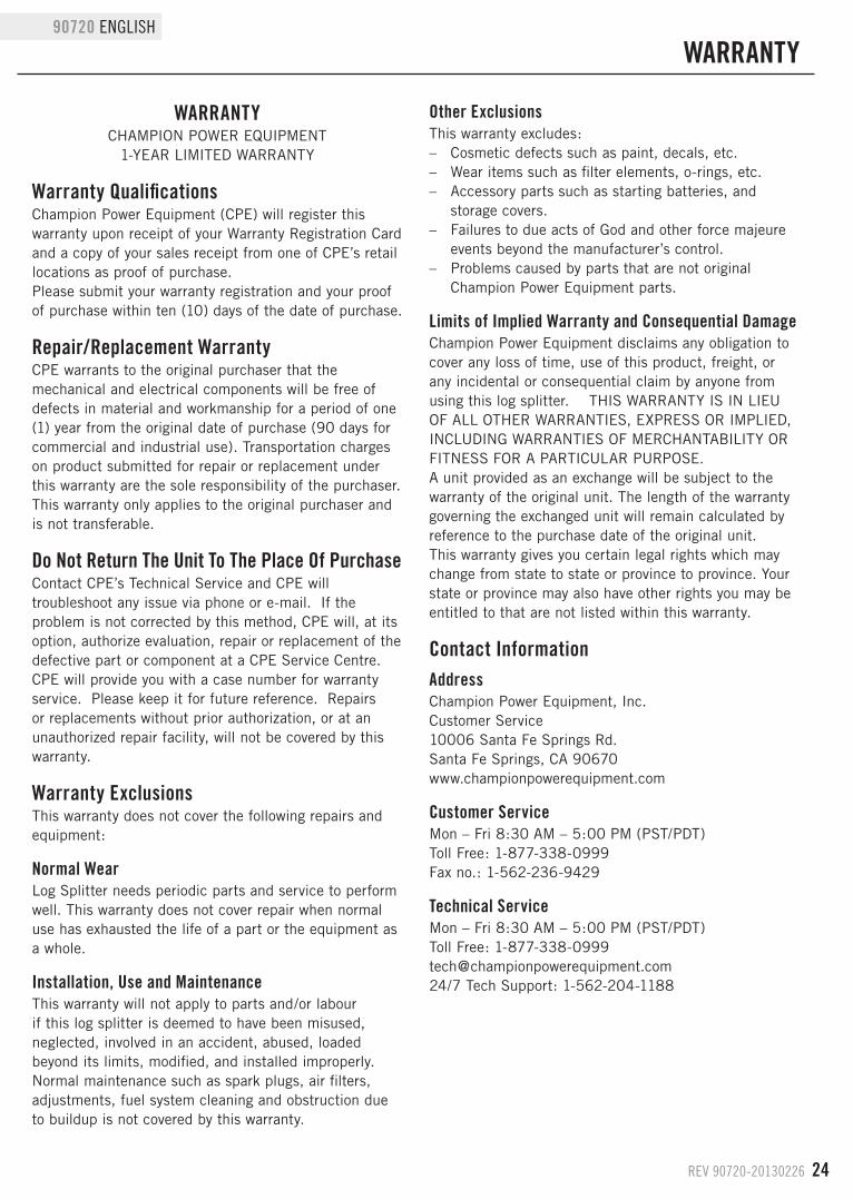
WARRANTy
WARRANTyCHAMPION POWER EQUIPMENT
1-YEAR LIMITED WARRANTY
Warranty QualificationsChampion Power Equipment (CPE) will register this warranty upon receipt of your Warranty Registration Card and a copy of your sales receipt from one of CPE’s retail locations as proof of purchase.Please submit your warranty registration and your proof of purchase within ten (10) days of the date of purchase.
Repair/Replacement WarrantyCPE warrants to the original purchaser that the mechanical and electrical components will be free of defects in material and workmanship for a period of one (1) year from the original date of purchase (90 days for commercial and industrial use). Transportation charges on product submitted for repair or replacement under this warranty are the sole responsibility of the purchaser. This warranty only applies to the original purchaser and is not transferable.
do Not Return The Unit To The Place Of PurchaseContact CPE’s Technical Service and CPE will troubleshoot any issue via phone or e-mail. If the problem is not corrected by this method, CPE will, at its option, authorize evaluation, repair or replacement of the defective part or component at a CPE Service Centre. CPE will provide you with a case number for warranty service. Please keep it for future reference. Repairs or replacements without prior authorization, or at an unauthorized repair facility, will not be covered by this warranty.
Warranty ExclusionsThis warranty does not cover the following repairs and equipment:
Normal WearLog Splitter needs periodic parts and service to perform well. This warranty does not cover repair when normal use has exhausted the life of a part or the equipment as a whole.
Installation, Use and MaintenanceThis warranty will not apply to parts and/or labour if this log splitter is deemed to have been misused, neglected, involved in an accident, abused, loaded beyond its limits, modified, and installed improperly. Normal maintenance such as spark plugs, air filters, adjustments, fuel system cleaning and obstruction due to buildup is not covered by this warranty.
Other ExclusionsThis warranty excludes: – Cosmetic defects such as paint, decals, etc. – Wear items such as filter elements, o-rings, etc. – Accessory parts such as starting batteries, and
storage covers. – Failures to due acts of God and other force majeure
events beyond the manufacturer’s control. – Problems caused by parts that are not original
Champion Power Equipment parts.
Limits of Implied Warranty and Consequential damageChampion Power Equipment disclaims any obligation to cover any loss of time, use of this product, freight, or any incidental or consequential claim by anyone from using this log splitter. THIS WARRANTY IS IN LIEU OF ALL OTHER WARRANTIES, EXPRESS OR IMPLIED, INCLUDING WARRANTIES OF MERCHANTABILITY OR FITNESS FOR A PARTICULAR PURPOSE. A unit provided as an exchange will be subject to the warranty of the original unit. The length of the warranty governing the exchanged unit will remain calculated by reference to the purchase date of the original unit.This warranty gives you certain legal rights which may change from state to state or province to province. Your state or province may also have other rights you may be entitled to that are not listed within this warranty.
Contact InformationAddressChampion Power Equipment, Inc.Customer Service10006 Santa Fe Springs Rd.Santa Fe Springs, CA 90670www.championpowerequipment.com
Customer ServiceMon – Fri 8:30 AM – 5:00 PM (PST/PDT)Toll Free: 1-877-338-0999Fax no.: 1-562-236-9429
Technical ServiceMon – Fri 8:30 AM – 5:00 PM (PST/PDT)Toll Free: [email protected]/7 Tech Support: 1-562-204-1188

Champion Power Equipment, Inc. (CPE), The United States Environment Protection Agency (U.S. EPA.) and the California Air Resources Board (CARB)
Emission Control System Warranty Your Champion Power Equipment (CPE) engine complies with both the U.S. EPA and state of California Air Resources Board (CARB) emission regulations. YOUR WARRANTY RIGHTS AND OBLIGATIONS: The US EPA, California Air Resources Board, and CPE are pleased to explain the Federal and California Emission Control Systems Warranty on your 2013 small off-road engine and engine powered equipment. In California, new, small off-road engines and new equipment that use small off-engines must be designed, built and equipped to meet the State’s stringent anti smog standards. In the other states, new engines and equipment must be designed, built and equipped, at the time of sale, to meet U.S. EPA regulations for small non-road engines. CPE warrants the emission control system on your small off-road engine and equipment for the period of time listed below, provided there has been no abuse, neglect, unapproved modification, or improper maintenance of your equipment. Your emission control system may include parts such as the carburetor, fuel-injection system, the ignition system, catalytic converter and fuel lines. Also included may be hoses, belts, connectors and other emission related assemblies. Where a warrantable condition exits, CPE will repair your small off-road engine at no cost to you including diagnosis, parts and labor. For engines less than or equal to 80cc, only the fuel tank and fuel line is subject to the evaporative emission control warranty requirements of this section. MANUFACTURER’S EMISSION CONTROL SYSTEM WARRANTY COVERAGE: This emission control system is warranted for two years, subject to provisions set forth below. If, during the warranty period, emission related part on your engine is defective in materials or workmanship, the part will be repaired or replaced by CPE. OWNER WARRANTY RESPONSIBILITIES: As the small off-road engine owner, you are responsible for the performance of the required maintenance listed in your Owner’s Manual. CPE recommends that you retain all your receipts covering maintenance on your small off-road engine, but CPE cannot deny warranty solely for the lack of receipts or for your failure to ensure the performance of all scheduled maintenance. As the small off-road engine owner, you should however be aware that CPE may deny you warranty coverage if your small, off-road engine or a part has failed due to abuse, neglect, improper maintenance or unapproved modifications. You are responsible for presenting your small off-road engine to an Authorized CPE service outlet or alternate service outlet as described in (3)(f.) below, CPE dealer or CPE, Santa Fe Springs, Ca. as soon as a problem exists. The warranty repairs should be completed in a reasonable amount of time, not to exceed 30 days. If you have any questions regarding your warranty rights and responsibilities, you should contact:
Champion Power Equipment, Inc. Customer Service
10006 Santa Fe Springs Road Santa Fe Springs, CA 90670
1-877-338-0999 [email protected]

EMISSION CONTROL SYSTEM WARRANTY The following are specific provisions relative to your Emission Control System (ECS) Warranty Coverage. 1. APPLICABILITY: This warranty shall apply to 1995 and later model year California small off-road engines (for other states, 1997 and later model year engines). The ECS Warranty Period shall begin on the date the new engine or equipment is delivered to its original, end-use purchaser, and shall continue for 24 consecutive months thereafter. 2. GENERAL EMISSIONS WARRANTY COVERAGE CPE warrants to the original, end-use purchaser of the new engine or equipment and to each subsequent purchaser that each of its small off-road engines is: a. Designed, built and equipped so as to conform to U.S. EPA emissions standards for spark-ignited engines at or below 19 kilowatts and all applicable regulations adopted by the California Air Resources Board and b. Free from defects in materials and workmanship that cause the failure of a warranted part to be identical in all material respects to the part as described in the engine manufacturer’s application for certification for a period of two years. 3. THE WARRANTY ON EMISSION-RELATED PARTS WILL BE INTERPRETED AS FOLLOWS: a. Any warranted part that is not scheduled for replacement as required maintenance in the Owners Manual shall be warranted for the ECS Warranty Period. If any such part fails during the ECS Warranty Period, it shall be repaired or replaced by CPE according to Subsection “d” below. Any such part repaired or replaced under the ECS Warranty shall be warranted for any remainder of the ECS Warranty Period. b. Any warranted, emissions-related part which is scheduled only for regular inspection as specified in the Owners Manual shall be warranted for the ECS Warranty Period. A statement in such written instructions to the effect of “repair or replace as necessary”, shall not reduce the ECS Warranty Period. Any such part repaired or replaced under the ECS Warranty shall be warranted for the remainder of the ECS Warranty Period. c. Any warranted, emissions-related part which is scheduled for replacement as required maintenance in the Owner’s Manual shall be warranted for the period of time prior to the first scheduled replacement point for that part. If the part fails prior to the first scheduled replacement, the part shall be repaired or replaced by CPE according to Subsection “d” below. Any such emissions-related part repaired or replaced under the ECS Warranty, shall be warranted for the remainder of the ECS Warranty Period prior to the first scheduled replacement point for such emissions-related part. d. Repair or replacement of any warranted, emissions-related part under this ECS Warranty shall be performed at no charge to the owner at a CPE Authorized Service Outlet. e. The owner shall not be charged for diagnostic labor which leads to the determination that a part covered by the ECS Warranty is in fact defective, provided that such diagnostic work is performed at a CPE Authorized Service Outlet. f. CPE shall pay for covered emissions warranty repairs at non-authorized service outlets under the following circumstances: i. The service is required in a population center with a population over 100,000 according to U.S. Census 2000 without a CPE Authorized Service Outlet AND ii. The service is required more than 100 miles from a CPE Authorized Service Outlet. The 100 mile limitation does not apply in the following states: Alaska, Arizona, Colorado, Hawaii, Idaho, Montana, Nebraska, Nevada, New Mexico, Oregon, Texas, Utah and Wyoming. g. CPE shall be liable for damages to other original engine components or approved modifications proximately caused by a failure under warranty of an emission-related part covered by the ECS Warranty. h. Throughout the ECS Warranty Period, CPE shall maintain a supply of warranted emission-related parts sufficient to meet the expected demand for such emission-related parts. i. Any CPE Authorized and approved emission-related replacement part may be used in the performance of any ECS Warranty maintenance or repair and will be provided without charge to the owner. Such use shall not reduce CPE’s warranty obligation. j. Unapproved add-on or modified parts may not be used to modify or repair a CPE engine. Such use voids this ECS Warranty and shall be sufficient grounds for disallowing an ECS Warranty claim. CPE shall not be liable hereunder for failures of any warranted parts of a CPE engine caused by the use of such an unapproved add-on or modified part.
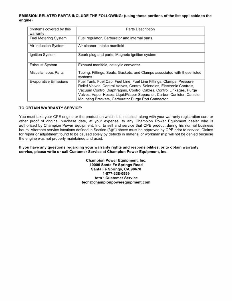
EMISSION-RELATED PARTS INCLUDE THE FOLLOWING: (using those portions of the list applicable to the engine)
Systems covered by this warranty
Parts Description
Fuel Metering System Fuel regulator, Carburetor and internal parts
Air Induction System Air cleaner, Intake manifold
Ignition System Spark plug and parts, Magneto ignition system
Exhaust System Exhaust manifold, catalytic converter
Miscellaneous Parts Tubing, Fittings, Seals, Gaskets, and Clamps associated with these listed systems.
Evaporative Emissions Fuel Tank, Fuel Cap, Fuel Line, Fuel Line Fittings, Clamps, Pressure Relief Valves, Control Valves, Control Solenoids, Electronic Controls, Vacuum Control Diaphragms, Control Cables, Control Linkages, Purge Valves, Vapor Hoses, Liquid/Vapor Separator, Carbon Canister, Canister Mounting Brackets, Carburetor Purge Port Connector
TO OBTAIN WARRANTY SERVICE: You must take your CPE engine or the product on which it is installed, along with your warranty registration card or other proof of original purchase date, at your expense, to any Champion Power Equipment dealer who is authorized by Champion Power Equipment, Inc. to sell and service that CPE product during his normal business hours. Alternate service locations defined in Section (3)(f.) above must be approved by CPE prior to service. Claims for repair or adjustment found to be caused solely by defects in material or workmanship will not be denied because the engine was not properly maintained and used. If you have any questions regarding your warranty rights and responsibilities, or to obtain warranty service, please write or call Customer Service at Champion Power Equipment, Inc.
Champion Power Equipment, Inc.
10006 Santa Fe Springs Road Santa Fe Springs, CA 90670
1-877-338-0999 Attn.: Customer Service