6159-5.1, industrial 17' crt monitor -...
TRANSCRIPT
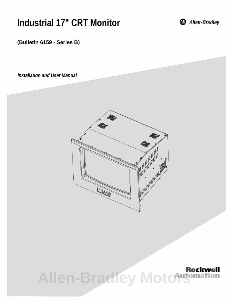
Industrial 17" CRT Monitor
(Bulletin 6159 - Series B)
Installation and User Manual
Allen-Bradley Motors
2 Table of Contents
Publication 6159-5.1
77DDEOH REOH RII &RQWH&RQWHQQWVWVIndustrial 17" CRT Monitor .............................................. 3Description........................................................................... 3Package Contents ................................................................. 4Installing the 6159 Industrial Monitor................................... 5Panel Mounting.................................................................... 6Connecting the 6159 Industrial Monitor................................ 12Operating the 6159 Industrial Monitor.................................. 16Routine Maintenance............................................................ 27Troubleshooting ................................................................... 28Appendix A: Touchscreen Serial Interface........................ 30Description........................................................................... 30Setting Up the Touchscreen Interface.................................... 30Performing a Calibration ...................................................... 32Appendix B: Video Cables................................................. 33Specifications...................................................................... 34
Important User Information Solid state equipment has operational characteristics differing from those ofelectromechanical equipment. "Safety Guidelines for the Application, Installation, andMaintenance of Solid State Controls" (Publication SGI-1.1) describes some importantdifferences between solid state equipment and hard-wired electromechanical devices.Because of this difference, and because of the wide variety of uses for solid stateequipment, all persons responsible for applying this equipment must satisfy themselvesthat each intended application of this equipment is acceptable.
In no event will Rockwell Automation be responsible or liable for indirect orconsequential damages resulting from the use or application of this equipment.
The examples and diagrams in this manual are included solely for illustrative purposes.Because of the many variables and requirements associated with any particularinstallation, Rockwell Automation cannot assume responsibility or liability for actualuse based on the examples and diagrams.
No patent liability is assumed by Rockwell Automation with respect to use of theinformation, circuits, equipment, or software described in this manual.
Reproduction of the contents of this manual, in whole or in part, without writtenpermission of Rockwell Automation is prohibited.
Throughout this manual, we use notes to make you aware of safety considerations.
ATTENTION: Identifies information about practices orcircumstances that can lead to personal injury or death,property damage, or economic loss.
Important: Identifies information that is especially important for successfulapplication and understanding of the product.
Industrial 17" CRT Monitor 3
Publication 6159-5.1
,QGXVWULDO,QGXVWULDO ���� &57 0RQLW�� &57 0RQLWRRUU
The Bulletin 6159 17" Industrial CRT Monitor is a general purposemonitor suitable for a wide range of industrial computing applications. Itoffers the following features:
• Reliable and rugged industrial design
• High-brightness
• Durable NEMA 4 sealed polycarbonate screen overlay
• Versatile multi-sync design (640 x 480 to 1280 x 1024 resolution)
Note: This monitor can display resolutions up to 1280 x 1024.If you experience unexpected results operating themonitor at this resolution, verify that the monitor isoperating at 60Hz.
ATTENTION: The equipment described in thisdocument generates, uses, and emits radio frequencyenergy. The equipment has been tested and found tocomply with FCC Rules, Part 15, subpart J, for Class Acomputing devices.
The use of non-shielded interface or power cords withAllen-Bradley industrial monitors is prohibited.
ATTENTION: X-ray emissions from these monitors aretypically about 0.05 mR/hr maximum, well below the 0.5mR/hr maximum recommended by the US. Department ofHealth and Human Resources and specified in "FederalPerformance Standards for Television Receivers", Section10, Part 1020, Title 21, of the U. S. Code of Regulation(PL90-620), Vol. 38, No. 198.
These monitors are equipped with X-ray protectioncircuits which cause automatic shutdown of theequipment in case its X-ray emissions begin to approachFederal limits.
Description
Allen-Bradley Motors
4 Industrial 17" CRT Monitor
Publication 6159-5.1
Available Options
The following options are available to the 6159 Industrial Monitor:
• Video interface options (HD-15)
• Touchscreen options (resistive, capacitive)
• Touchscreen cable options
• Video cable options
• Power cord options
The monitor shipping carton contains the following items:
• Monitor
• Package of mounting hardware
• AC power cord (optional)
• Video cable (optional)
• This user manual
A 6159 Industrial Monitor with a touchscreen option is shipped withthese additional items:
• Supporting software and manuals
• RS-232 serial extension cable (optional)
Unpacking the Unit
Before unpacking a new monitor, inspect the shipping carton fordamage. If damage is visible, immediately contact the shipper andrequest assistance. Otherwise, proceed with unpacking.
Note: Make sure you keep the original packaging for the monitorin case you need to return the monitor for repair.
Package Contents
Industrial 17" CRT Monitor 5
Publication 6159-5.1
This section describes how to install the monitor.
Tools Needed
In addition to the tools required to make the cutout, you will need thefollowing tools:
• 3/8” Deep Well Socket
• 1/4” Drive Extension - 12” or longer
• 1/4” Drive Ratchet or 1/4” Drive Torque Ratchet
Before Installation
When installing the unit, it is important to consider environmentalfactors at the site that could affect performance as well as possibleeffects from equipment operation on personnel and nearby equipment.
Following the guidelines will help ensure that the monitor will providesafe and reliable service.
• Ensure that sufficient power is available from a single phase ACoutlet at the site.
• Ensure that sufficient space is available around air inlets and outletsto provide the circulation necessary for cooling. Never allow airpassages to become obstructed. The monitor is equipped with a fanto ensure proper cooling.
• Dust and smoke particles can cause problems, since they can collectat ventilating holes in the enclosure and interfere with cooling.Accordingly, where dust and smoke are problems it is especiallyimportant to keep air vents clean. Refer to the Routine Maintenancesection (Page 27) for more information.
• Ensure that the ambient air temperature will not exceed thespecified maximum temperature. A user supplied fan, heat exchangeror air conditioner may be required to meet this condition in someinstallations.
• Leave the monitor’s enclosure or cover in place at all times duringoperation. The cover affords protection against high voltages insidethe monitor and inhibits radio-frequency emissions that mightinterfere with other equipment.
• The Federal Communications Commission has prepared a pamphletthat addresses the problem of radio frequency interference to radioand television reception, which should be consulted in case ofproblems with such interference. This publication, “How to Identifyand Resolve Radio/TV Interference Problems” (Stock #004-000-00345-4) may be obtained from the US. Government Printing Office,Washington, DC 20402.
Installing the 6159Industrial Monitor
Allen-Bradley Motors
6 Industrial 17" CRT Monitor
Publication 6159-5.1
• Determine the minimum and maximum ambient humidity for themonitor by consulting the specification sheets at the back of thismanual. Ensure that the humidity of the ambient air will not exceedthese limits. In very dry environments, static charges build up veryreadily. Proper grounding of the equipment through the AC powercord can help reduce the likelihood of static discharges, which maycause shocks and damage electronic components.
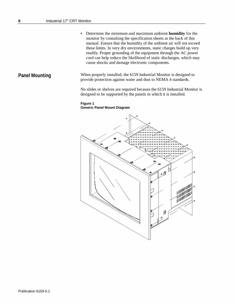
When properly installed, the 6159 Industrial Monitor is designed toprovide protection against water and dust to NEMA 4 standards.
No slides or shelves are required because the 6159 Industrial Monitor isdesigned to be supported by the panels in which it is installed.
Figure 1Generic Panel Mount Diagram
Panel Mounting
Industrial 17" CRT Monitor 7
Publication 6159-5.1
Panel Mounting Guidelines
Observe the following precautions before installing the unit in a panel:
• Confirm that there is adequate space behind the panel. Remember toallow extra space (63.5 mm (2.5 in) behind and25.4 mm (1 in) belowand on each side) for air circulation and cabling. Allow 12.7 mm(0.5 in.) top clearance for mounting.
• Confirm that the cabinet is deep enough to accommodate themonitor's depth while providing rear clearance for airflow. A cabinetwith depth of 449.3 mm (17.69 in.) is sufficient.
• Take precautions so that metal cuttings do not enter any componentsthat are already installed in the panel.
• Supporting panels should be at least 14 gauge to ensure propersealing against water and dust and to provide proper support. Themounting hardware supplied accommodates panels up to 6.4 mm(0.25 in) thick.
Note: Supporting panels must be cut and drilled tospecifications prior to installation.
ATTENTION: Failure to follow these warnings mayresult in personal injury or damage to the panelcomponents.
Allen-Bradley Motors
8 Industrial 17" CRT Monitor
Publication 6159-5.1
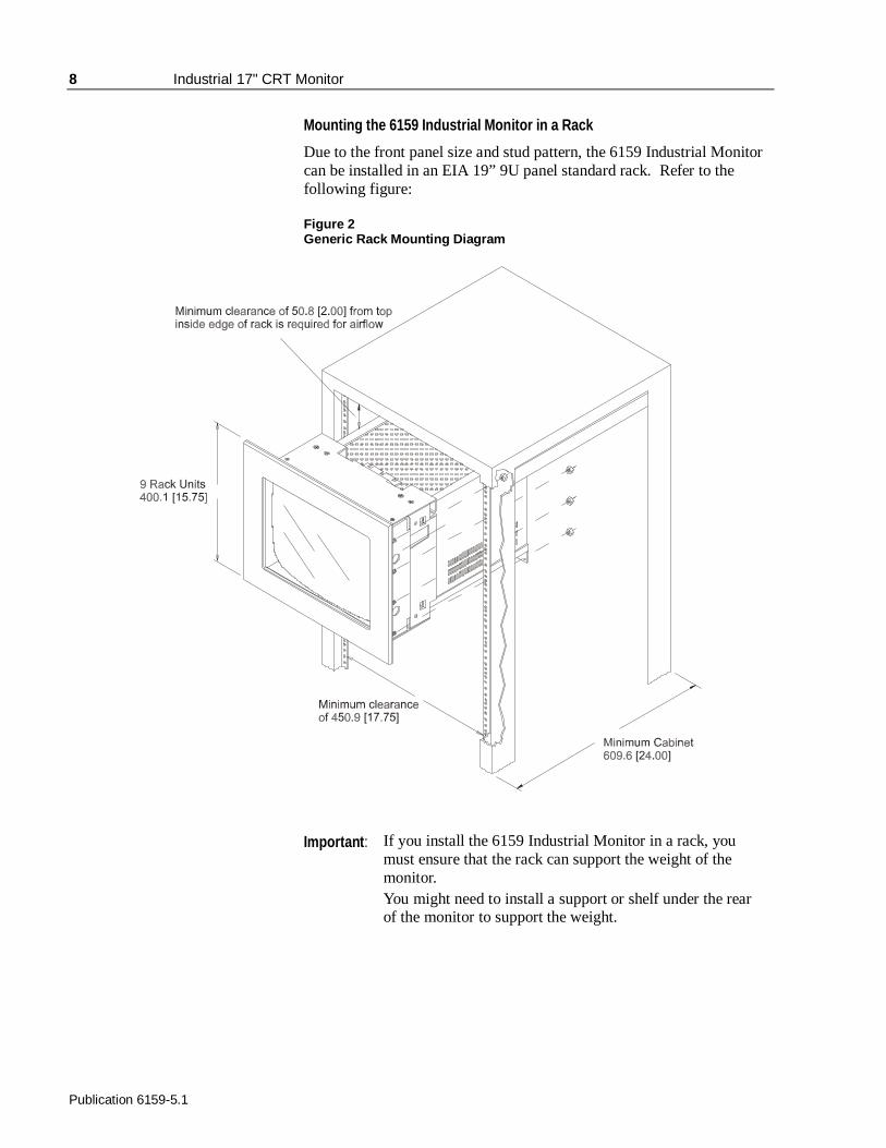
Mounting the 6159 Industrial Monitor in a Rack
Due to the front panel size and stud pattern, the 6159 Industrial Monitorcan be installed in an EIA 19” 9U panel standard rack. Refer to thefollowing figure:
Figure 2Generic Rack Mounting Diagram
Important : If you install the 6159 Industrial Monitor in a rack, youmust ensure that the rack can support the weight of themonitor.You might need to install a support or shelf under the rearof the monitor to support the weight.
Industrial 17" CRT Monitor 9
Publication 6159-5.1
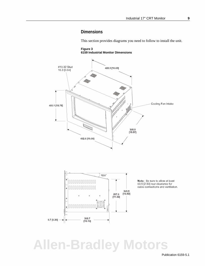
Dimensions
This section provides diagrams you need to follow to install the unit.
Figure 36159 Industrial Monitor Dimensions
Allen-Bradley Motors
10 Industrial 17" CRT Monitor
Publication 6159-5.1
Panel Mounting Procedure
1. Confirm that the shipping carton contains a package of 20 10-32 locknuts and 20 flat washers. You will need 18 nuts and washers forinstallation.
2. Refer to the physical dimension drawing (Figure 3) and confirm thatthere is adequate space behind the panel. Remember to allow extraspace for circulation and cabling.
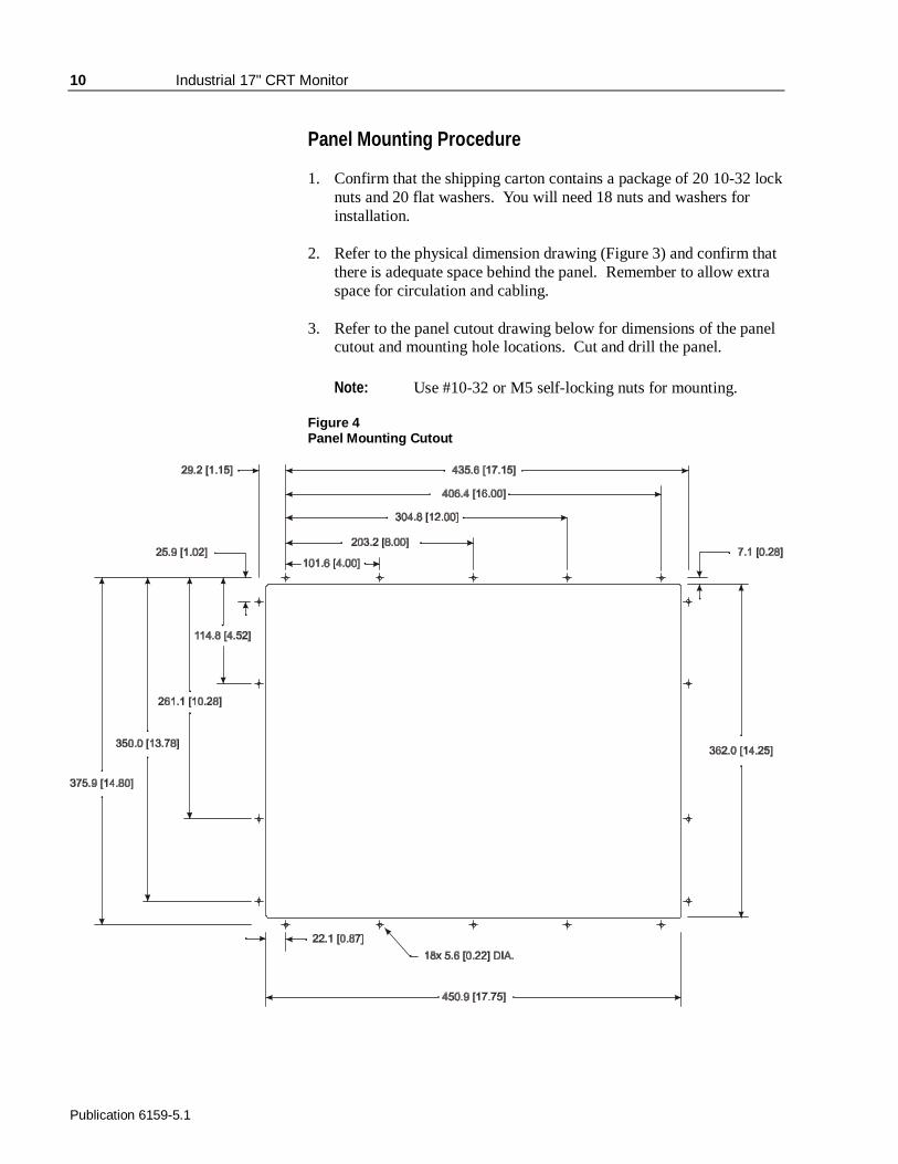
3. Refer to the panel cutout drawing below for dimensions of the panelcutout and mounting hole locations. Cut and drill the panel.
Note: Use #10-32 or M5 self-locking nuts for mounting.
Figure 4Panel Mounting Cutout
Industrial 17" CRT Monitor 11
Publication 6159-5.1
4. Carefully remove the monitor from its packaging. Avoid damagingthe monitor gasket.
Tip: It will be easier to install the monitor if you support it with a shelfor other support adjusted to the appropriate height.
5. Insert the monitor in the panel cutout from the front. Do not damagethe threaded mounting studs as you position the monitor.
6. Secure the unit with the lock nuts and washers provided. Tightenevenly to 24 inch-pounds of torque.
Important : To ensure a proper seal, be sure to install a washer andnut on each of the 18 mounting studs.
ATTENTION: Mounting nuts must be tightened to atorque of 24 inch-pounds to provide panel seal andavoid potential damage. Rockwell Automationassumes no responsibility for water or chemicaldamage to the monitor or other equipment within theenclosure due to improper installation.
7. Remove the protective adhesive sheet from the screen of theIndustrial Monitor. The sheet is designed to prevent scratching ofthe polycarbonate screen protector or the optional touchscreenduring shipping and installation. It should be removed before use.
Allen-Bradley Motors
12 Industrial 17" CRT Monitor
Publication 6159-5.1
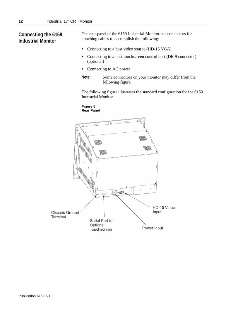
The rear panel of the 6159 Industrial Monitor has connectors forattaching cables to accomplish the following:
• Connecting to a host video source (HD-15 VGA)
• Connecting to a host touchscreen control port (DE-9 connector)(optional)
• Connecting to AC power
Note: Some connectors on your monitor may differ from thefollowing figure.
The following figure illustrates the standard configuration for the 6159Industrial Monitor.
Figure 5Rear Panel
Connecting the 6159Industrial Monitor
Industrial 17" CRT Monitor 13
Publication 6159-5.1
Connecting the Video Source
The video connection to the host is made through a HD-15 (female)connector.
To establish a signal using the HD-15 connector:
Note: For more information on using an HD-15 video cable toconnect to the host computer, refer to Appendix B(Page 33).
1. Obtain a shielded, properly terminated video cable of length as shortas possible. Longer cables (up to approximately 50 feet in somecases) may be used, provided they are properly constructed. Yourpackage may include a 6- or 15-foot video cable, if specified.
2. Connect one end of the cable to the female HD-15 video inputconnector on the rear panel of the monitor.
3. Connect the other end to the output of any IBM-compatible VGAadapter or other video generator.
Note: You may connect the monitor to video generators thatdo not conform to VGA standards. The mainrequirement is that the generator provide analog RGBvideo signals (0.714V or 1V above reference black into75 ohms) and separate horizontal and vertical syncsignals. For information on setting the video inputlevel, refer to Page 25.
Allen-Bradley Motors
14 Industrial 17" CRT Monitor
Publication 6159-5.1
Connecting the Touchscreen Interface
The serial touchscreen interface connection to the host is made throughan RS-232 DE-9 (female) connector located on the rear panel.
The optional touchscreen provides a high-resolution touch input system.Driver software included with the package allows the touchscreen tofunction with many popular DOS and Windows®-based industrialapplications as a pointing device (mouse).
Note: Refer to the manual included with the touchscreen optionand Appendix A of this manual (page 30) for additionaldetails on the installation and operation of the touchscreen.
To connect the touchscreen:
1. For units with the touchscreen option, make sure you have one of theoptional serial cables.
2. Connect one end of the touchscreen serial cable to the T/S portconnector on the rear of the monitor.
3. Connect the other end to any serial communications port on the hostcomputer.
4. Tighten the captive screws on the cable connector to secure it.
Industrial 17" CRT Monitor 15
Publication 6159-5.1
Connecting AC Power
The 6159 Industrial Monitor requires a single phase power supplyproviding 100 to 240V AC at 50 or 60 Hz. Power must be available at agrounded three-pin outlet located nearby. Whenever possible, connectthe monitor to the same AC source that supplies the computer.
To connect AC power to the monitor:
1. Turn off the main switch or breaker.
2. Use the ground terminal of the monitor to establish a chassis-to-earthground connection. Secure one end of a ground strap to the groundterminal. Connect the other end of the ground strap to a good earthground.
The ground terminal is an M5 screw.
ATTENTION: Chassis ground must be connected forsafe operation of the monitor. The AC receptacle on themonitor is a 3-wire type with chassis ground pin, and themating AC cord supplied is a 3-wire type, designed forconnection to a grounded 3-pin AC outlet. However, aproperly ground AC outlet is not always available, andgrounding using a 3-wire cord can easily be defeated. Ifyou fail to ground the monitor properly, the setup mayresult in personal injury from electrical shock or damageto the equipment.
3. Connect the socket end of the AC power cord to the matingconnector on the rear panel of the monitor.
4. Connect the plug end of the AC power cord to the main outlet.
5. Restore AC power to the outlet.
Allen-Bradley Motors
16 Industrial 17" CRT Monitor
Publication 6159-5.1
This section describes how to operate the 6159 Industrial Monitor.
Operator Controls and Indicators
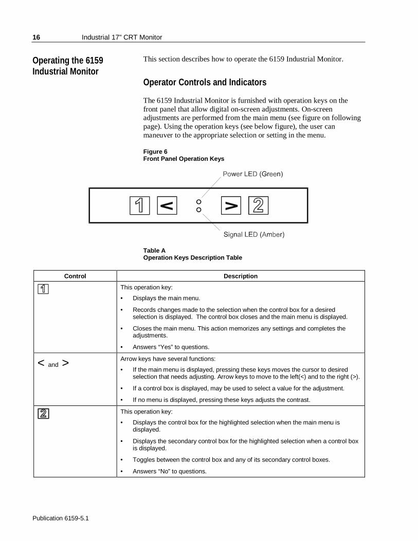
The 6159 Industrial Monitor is furnished with operation keys on thefront panel that allow digital on-screen adjustments. On-screenadjustments are performed from the main menu (see figure on followingpage). Using the operation keys (see below figure), the user canmaneuver to the appropriate selection or setting in the menu.
Figure 6Front Panel Operation Keys
Table AOperation Keys Description Table
Control Description
This operation key:
• Displays the main menu.
• Records changes made to the selection when the control box for a desiredselection is displayed. The control box closes and the main menu is displayed.
• Closes the main menu. This action memorizes any settings and completes theadjustments.
• Answers “Yes” to questions.
< and > Arrow keys have several functions:
• If the main menu is displayed, pressing these keys moves the cursor to desiredselection that needs adjusting. Arrow keys to move to the left(<) and to the right (>).
• If a control box is displayed, may be used to select a value for the adjustment.
• If no menu is displayed, pressing these keys adjusts the contrast.
This operation key:
• Displays the control box for the highlighted selection when the main menu isdisplayed.
• Displays the secondary control box for the highlighted selection when a control boxis displayed.
• Toggles between the control box and any of its secondary control boxes.
• Answers “No” to questions.
Operating the 6159Industrial Monitor
Industrial 17" CRT Monitor 17
Publication 6159-5.1
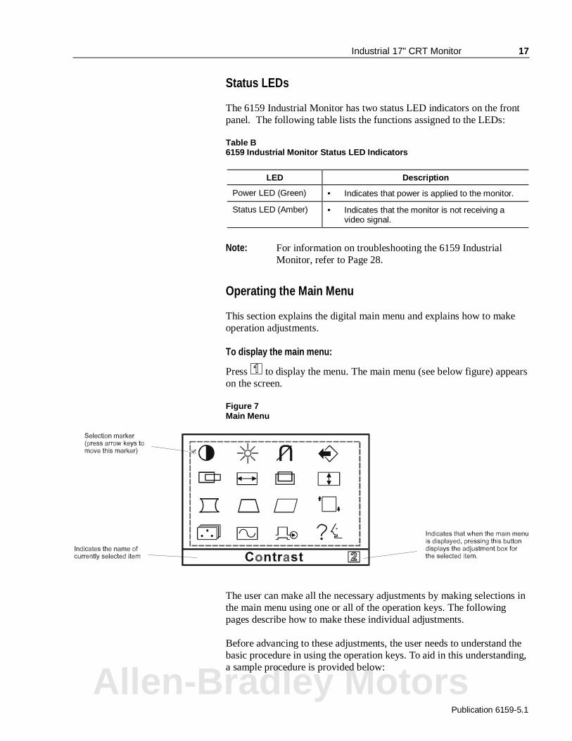
Status LEDs
The 6159 Industrial Monitor has two status LED indicators on the frontpanel. The following table lists the functions assigned to the LEDs:
Table B6159 Industrial Monitor Status LED Indicators
LED Description
Power LED (Green) • Indicates that power is applied to the monitor.
Status LED (Amber) • Indicates that the monitor is not receiving avideo signal.
Note: For information on troubleshooting the 6159 IndustrialMonitor, refer to Page 28.
Operating the Main Menu
This section explains the digital main menu and explains how to makeoperation adjustments.
To display the main menu:
Press to display the menu. The main menu (see below figure) appearson the screen.
Figure 7Main Menu
The user can make all the necessary adjustments by making selections inthe main menu using one or all of the operation keys. The followingpages describe how to make these individual adjustments.
Before advancing to these adjustments, the user needs to understand thebasic procedure in using the operation keys. To aid in this understanding,a sample procedure is provided below:
Allen-Bradley Motors
18 Industrial 17" CRT Monitor
Publication 6159-5.1
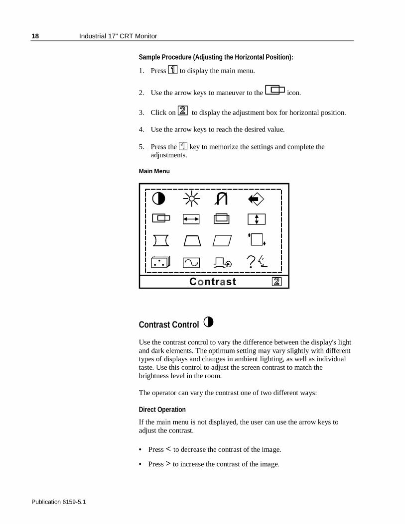
Sample Procedure (Adjusting the Horizontal Position):
1. Press to display the main menu.
2. Use the arrow keys to maneuver to the icon.
3. Click on to display the adjustment box for horizontal position.
4. Use the arrow keys to reach the desired value.
5. Press the key to memorize the settings and complete theadjustments.
Main Menu
Contrast Control
Use the contrast control to vary the difference between the display's lightand dark elements. The optimum setting may vary slightly with differenttypes of displays and changes in ambient lighting, as well as individualtaste. Use this control to adjust the screen contrast to match thebrightness level in the room.
The operator can vary the contrast one of two different ways:
Direct Operation
If the main menu is not displayed, the user can use the arrow keys toadjust the contrast.
• Press < to decrease the contrast of the image.
• Press > to increase the contrast of the image.

Industrial 17" CRT Monitor 19
Publication 6159-5.1
Note: Pressing the arrow keys simultaneously sets the standardlevel.
Using the Contrast adjustment box
1. Display the Contrast adjustment box.
2. Use the arrow keys to select a value.
• Press < to decrease the contrast of the image.
• Press > to increase the contrast of the image.
3. Press the key to memorize the settings and complete theadjustments.
Brightness Control
Use the brightness control to adjust the overall intensity of the display.After allowing the CRT to warm up for at least a minute, adjust for theleast amount of brightness needed to make the display clearly viewable.
Adjust the brightness to match the brightness level in the room so thatthe level will be easy to see.
1. Display the Brightness adjustment box.
2. Use the arrow keys to select a value.
• Press < to decrease the brightness of the image.
• Press > to increase the brightness of the image
Note: Pressing the arrow keys simultaneously while theBrightness adjustment box is displayed sets thestandard level.
3. Press the key to memorize the settings and complete theadjustments.
Degauss
The display screen is degaussed automatically each time the monitor ispowered on. This degaussing eliminates color impurities and otherdistortions of the display by neutralizing the effects of magnetic fields inthe surrounding environment.
Allen-Bradley Motors
20 Industrial 17" CRT Monitor
Publication 6159-5.1
When the unit is left on for a long period, or is repositioned followingpower-up, the screen may pick up additional magnetic flux, causingcolors to appear "blotchy" or otherwise distorted. For full effectiveness,allow at least fifteen minutes between manual degaussings. Shorterintervals may result in an incomplete removal of flux and residual colorimpurities.
Note: The internal degauss will not prevent color impuritiescaused by local magnetic fields. Metal enclosures caneasily become magnetized by welding and machineryoperations.Use a hand held degaussing coil to remove residualmagnetism from the enclosure.
Note: If the unit is located near electric transformers, motors,loudspeakers or other strong magnetic sources, degaussingalone may not be sufficient to eliminate interference. Tryreorienting the unit relative to the magnetic source ormoving the monitor further away.If this still does not solve the problem, contact RockwellAutomation about magnetic shielding.
The degaussing operates for approximately five (5) seconds afterselection. In this duration, the front panel keys are not operational.
Memory Recall
Use this selection to return to the initial factory settings. A menudisplays asking if you want to return to the initial settings.
1. Display the Memory Recall adjustment box.
2. Make the appropriate selections.
• For YES, press . This action recalls the original settings andreturns you to the main menu.
• For NO, press . This action returns you to the main menuwithout recalling the original settings.
Note: This adjustment box disappears after a 30-secondinactivity period.
3. Press the key to memorize the settings and complete theadjustments.
Industrial 17" CRT Monitor 21
Publication 6159-5.1
Horizontal Position
Centers the image horizontally on the screen.
1. Display the Horizontal Position adjustment box.
2. Use the arrow keys to select a value
Note: Pressing toggles between the horizontal size andhorizontal position control boxes.
• Press < to move the image to the left.
• Press > to move the image to the right.
3. Press the key to memorize the settings and complete theadjustments.
Horizontal Size
Makes the image wider or narrower.
Note: Before adjusting the horizontal size, first center the imagein the screen.Pressing toggles between the horizontal size andhorizontal position control boxes.
1. Display the Horizontal Size adjustment box.
2. Use the arrow keys to select a value
• Press < to decrease the size of the image horizontally.
• Press > to increase the size of the image horizontally.
3. Press the key to memorize the settings and complete theadjustments.
Allen-Bradley Motors
22 Industrial 17" CRT Monitor
Publication 6159-5.1
Vertical Position
Centers the image vertically on the screen.
Note: Pressing toggles between the vertical size and verticalposition control boxes.
1. Display the Vertical Position adjustment box.
2. Use the arrow keys to select a value
• Press < to move the image down.
• Press > to move the image up.
3. Press the key to memorize the settings and complete theadjustments.
Vertical Size
Makes the image taller or shorter.
Note: Before adjusting the vertical size, first center the image inthe screen.
Note: Pressing toggles between the vertical size and verticalposition control boxes.
1. Display the Vertical Size adjustment box.
2. Use the arrow keys to select a value
• Press < to decrease the size of the image vertically.
• Press > to increase the size of the image vertically.
3. Press the key to memorize the settings and complete theadjustments.
Industrial 17" CRT Monitor 23
Publication 6159-5.1
Vertical Pincushion
Corrects the image for barrel distortion.
1. Display the Vertical Pincushion adjustment box.
2. Use the arrow keys to select a value
• Press < to curve the screen image’s edges inwards.
• Press > to curve the screen image’s edges outwards.
3. Press the key to memorize the settings and complete theadjustments.
Trapezoid
Corrects the image for trapezoidal distortion.
1. Display the Trapezoid adjustment box.
2. Use the arrow keys to select a value
• Press < to make the image narrower at the top.
• Press > to make the image wider at the top.
3. Press the key to memorize the settings and complete theadjustments.
Parallelogram
Corrects the image for parallelogram distortion.
1. Display the Parallelogram adjustment box.
2. Use the arrow keys to select a value
• Press < to skew the image leftward.
• Press > to skew the image rightward.
3. Press the key to memorize the settings and complete theadjustments.
Allen-Bradley Motors
24 Industrial 17" CRT Monitor
Publication 6159-5.1
Rotation
Adjusts for tilt of the image on the screen.
1. Display the Rotation adjustment box.
2. Use the arrow keys to select a value
• Press < to tilt the image to the left.
• Press > to tilt the image to the right.
3. Press the key to memorize the settings and complete theadjustments.
Color Temperature
Adjusts the color white in an image (in Kelvin). The higher thetemperature, the redder, or warmer, the image color scheme. The lowerthe temperature, the bluer, or colder, the image color scheme.
Note: Before making any adjustments, record the initial colorsetting because memory recall will not reset this value.
1. Display the Color Temperature adjustment box.
2. Press the < and > arrow keys to make one or the followingselections:
• 1 : 9300K
• 2 : 6550K
• 3: User-defined temperature value
3. If you selected “3”, the icon displays in the lower-right corner ofthe Color Adjustment control box. This instructs the user to press to display the User Color Adjustment control box..
4. To enter a user-defined value, you must manually set the red, green,and blue values.
Industrial 17" CRT Monitor 25
Publication 6159-5.1
5. To adjust the value, press to advance to the appropriate color.
Press the < and > arrow keys to adjust the value of the selectedcolor (0-255).
6. Press the key to memorize the settings and complete theadjustments.
Display Frequency
This option displays the input synchronization signal frequency. Displaythe Display Frequency adjustment box to view signal.
Video Input Level
This option allows the user to match the video input signal level to thecomputer being used. The user can choose from one of two selections(0.7V or 1V).
1. Display the Video Input Level adjustment box.
2. Press to toggle to the correct selection.
3. Press the key to memorize the settings and complete theadjustments.
Language Selection
The user can alter the language of the on-screen menu. Selectionsinclude German, French, English, Italian, and Spanish.
1. Display the Language Selection adjustment box.
2. Press the < or > arrow keys to move ; to the correct selection.
3. Press the key to memorize the settings and complete theadjustments.
Allen-Bradley Motors
26 Industrial 17" CRT Monitor
Publication 6159-5.1
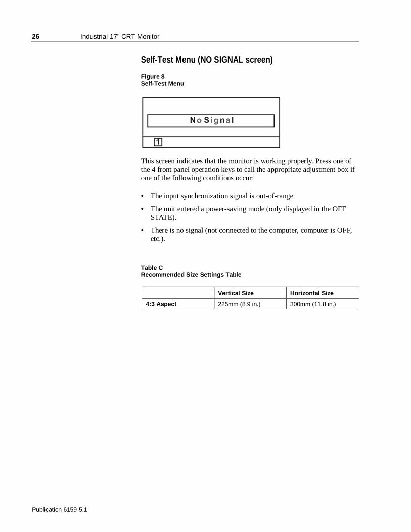
Self-Test Menu (NO SIGNAL screen)
Figure 8Self-Test Menu
This screen indicates that the monitor is working properly. Press one ofthe 4 front panel operation keys to call the appropriate adjustment box ifone of the following conditions occur:
• The input synchronization signal is out-of-range.
• The unit entered a power-saving mode (only displayed in the OFFSTATE).
• There is no signal (not connected to the computer, computer is OFF,etc.).
Table CRecommended Size Settings Table
Vertical Size Horizontal Size
4:3 Aspect 225mm (8.9 in.) 300mm (11.8 in.)
Industrial 17" CRT Monitor 27
Publication 6159-5.1
Cleaning
Occasionally clean the display panel and cabinet with a soft clothdampened (not soaked) with a mild (non-abrasive) glass cleaner. Keepturning a fresh side of the cloth toward the screen surface to avoidscratching it with accumulated grit.
Note: The solvent should be applied only to the cloth, and notdirectly on the monitor screen.Do not use paper products as they may scratch the surface.To minimize the risk of abrasion, allow the screen tostand dry.
Special care should be taken when cleaning a resistive touchscreen orpolycarbonate shield that is installed over the screen. Abrasive andcertain chemical cleaners can easily damage the surface.
Replacing a Line Cord
To avoid shock and fire hazards, the monitor’s power cord should bereplaced if the insulation becomes broken or if it develops a looseinternal connection.
Other Maintenance
Qualified service personnel should perform all maintenance, except forthe power cord replacement described above.
Routine Maintenance
Allen-Bradley Motors
28 Industrial 17" CRT Monitor
Publication 6159-5.1
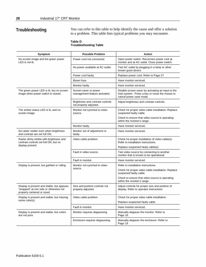
You can refer to this table to help identify the cause and offer a solutionto a problem. This table lists typical problems you may encounter.
Table DTroubleshooting Table
Symptom Possible Problem Action
No screen image and the green powerLED is not lit.
Power cord not connected. Open power switch. Reconnect power cord atmonitor and at AC outlet. Close power switch.
No power available at AC outlet. Test AC outlet by plugging in a lamp or otherknown good device.
Power cord faulty. Replace power cord. Refer to Page 27.
Blown fuse. Have monitor serviced.
Monitor faulty. Have monitor serviced.
The green power LED is lit, but no screenimage when power switch is closed.
Screen saver or powermanagement feature activated.
Disable screen saver by activating an input to thehost system. Press a key or move the mouse tocancel power save mode.
Brightness and contrast controlsnot properly adjusted.
Adjust brightness and contrast controls.
The amber status LED is lit, and noscreen image.
Monitor not synched to videosource.
Check for proper video cable installation. Replacesuspected faulty cable.
Check to ensure that video source is operatingwithin the monitor’s range.
Monitor faulty. Have monitor serviced.
No raster visible even when brightnessand contrast are set full ON.
Monitor out of adjustment orfaulty.
Have monitor serviced.
Raster dimly visible with brightness andcontrast controls set full ON, but nodisplay present
Video cable problem. Check for proper installation of video cable(s).Refer to installation instructions.
Replace suspected faulty cable(s).
Fault in video source. Test video source by connecting to anothermonitor that is known to be operational.
Fault in monitor. Have monitor serviced.
Display is present, but garbled or rolling Monitor not synched to videosource.
Refer to installation instructions.
Check for proper video cable installation. Replacesuspected faulty cable.
Check to ensure that video source is operatingwithin the monitor’s range.
Display is present and stable, but appears“wrapped” at one side or otherwise notproperly centered or sized.
Size and position controls notproperly adjusted.
Adjust controls for proper size and position ofdisplay. Refer to operator instructions
Display is present and stable, but missingsome color(s)
Video cable problem. Check for proper video cable installation.
Replace suspected faulty cable.
Fault in monitor. Have monitor serviced.
Display is present and stable, but colorsare not pure
Monitor requires degaussing. Manually degauss the monitor. Refer toPage 19.
Enclosure requires degaussing. Manually degauss the enclosure. Refer toPage 19.
Troubleshooting
Industrial 17" CRT Monitor 29
Publication 6159-5.1
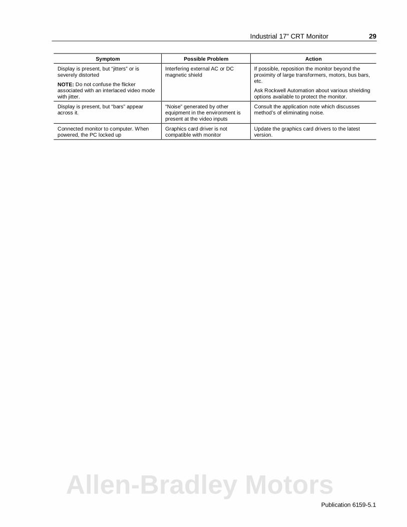
Symptom Possible Problem Action
Display is present, but “jitters” or isseverely distorted
NOTE: Do not confuse the flickerassociated with an interlaced video modewith jitter.
Interfering external AC or DCmagnetic shield
If possible, reposition the monitor beyond theproximity of large transformers, motors, bus bars,etc.
Ask Rockwell Automation about various shieldingoptions available to protect the monitor.
Display is present, but “bars” appearacross it.
“Noise” generated by otherequipment in the environment ispresent at the video inputs
Consult the application note which discussesmethod’s of eliminating noise.
Connected monitor to computer. Whenpowered, the PC locked up
Graphics card driver is notcompatible with monitor
Update the graphics card drivers to the latestversion.
Allen-Bradley Motors
30 Industrial 17" CRT Monitor
Publication 6159-5.1
$$SSHQGL[ $�SSHQGL[ $� 77RXRXFFKVFKVFUUHHQ 6HHQ 6HHULDOULDO
,QWHUIDFH,QWHUIDFH
All touch controllers are configured by default to provide serialcommunications at 9600 baud, 8 data bits, 1 stop bit, no parity.
For Allen-Bradley monitors equipped with touchscreens, a serialcommunications cable is required. A suitable cable can be obtained fromRockwell Automation or you can create one.
The cable provides a communications channel between the touchscreencontroller, which is mounted inside the monitor, and an RS-232-C serialport on the host computer. Because the touch controller obtains powerfrom the monitor's power supply, no external touch power connectionsare necessary.
Software supplied with the touchscreen must be loaded on the hostcomputer to handle communications with the touch controller over thechannel.
Because the touchscreen emulates a mouse, there may be compatibilityissues involving how the touchscreen emulates mouse buttons, especiallymultiple buttons. For a complete discussion of these issues and how totroubleshoot them, refer to the touchscreen documentation.
This section describes how to set up the touchscreen system using the6159 Industrial Monitor. Setup involves the following:
• Enabling the touchscreen interface
• Installing the software on the host computer that will handlecommunications with the touchscreen controller
• Performing a calibration
Enabling the Touchscreen Interface
The 6159 Industrial Monitor provides a female DE-9 connector on therear panel. This connector provides the serial interface for the touchcontroller.
Description
Setting Up theTouchscreen Interface
Industrial 17" CRT Monitor 31
Publication 6159-5.1
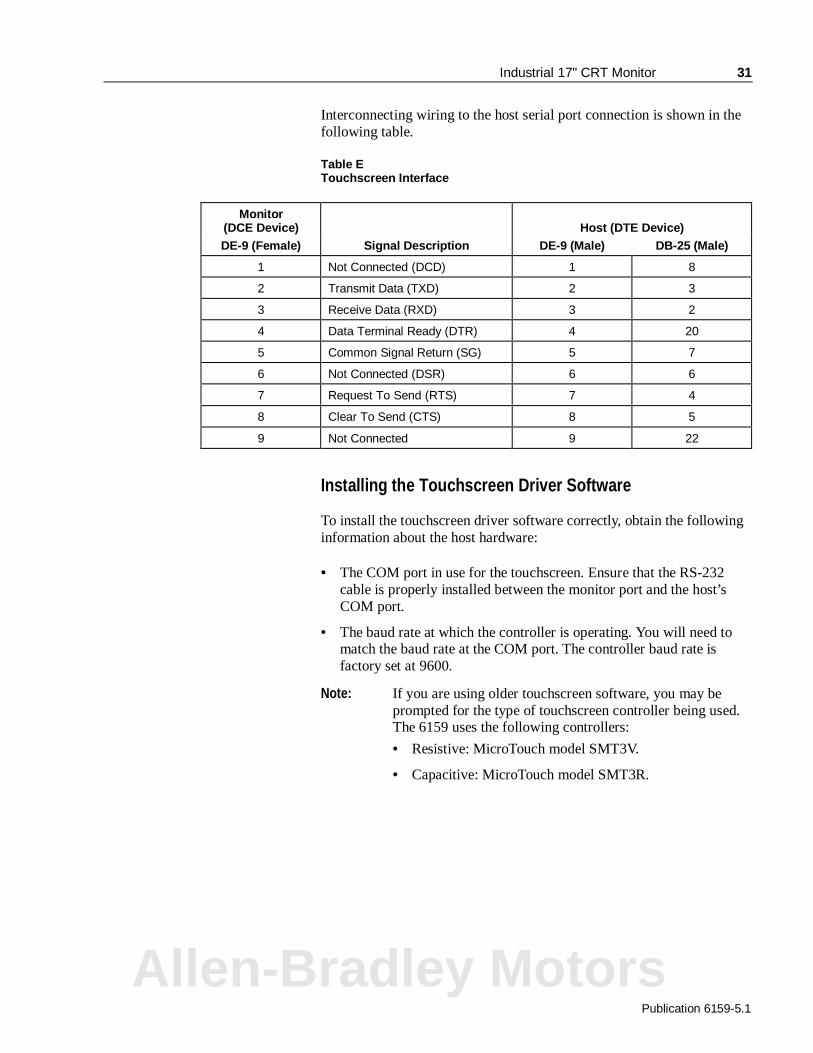
Interconnecting wiring to the host serial port connection is shown in thefollowing table.
Table ETouchscreen Interface
Monitor(DCE Device) Host (DTE Device)DE-9 (Female) Signal Description DE-9 (Male) DB-25 (Male)
1 Not Connected (DCD) 1 8
2 Transmit Data (TXD) 2 3
3 Receive Data (RXD) 3 2
4 Data Terminal Ready (DTR) 4 20
5 Common Signal Return (SG) 5 7
6 Not Connected (DSR) 6 6
7 Request To Send (RTS) 7 4
8 Clear To Send (CTS) 8 5
9 Not Connected 9 22
Installing the Touchscreen Driver Software
To install the touchscreen driver software correctly, obtain the followinginformation about the host hardware:
• The COM port in use for the touchscreen. Ensure that the RS-232cable is properly installed between the monitor port and the host’sCOM port.
• The baud rate at which the controller is operating. You will need tomatch the baud rate at the COM port. The controller baud rate isfactory set at 9600.
Note: If you are using older touchscreen software, you may beprompted for the type of touchscreen controller being used.The 6159 uses the following controllers:
• Resistive: MicroTouch model SMT3V.
• Capacitive: MicroTouch model SMT3R.
Allen-Bradley Motors
32 Industrial 17" CRT Monitor
Publication 6159-5.1
Once you have obtained this information, install the software using theinstallation disks found in the touchscreen accessory package.
Note: Before installation, you may want to check the touchscreenmanufacturer’s site on the World Wide Web for the latestsoftware drivers. Enter the following address in yourInternet browser to access the manufacturer’s web site: www.microtouch.comLook for one of the following product names on the website:
• TouchTek5 resistive touchscreen
• ClearTek capacitive touchscreen
After installing the driver software, follow the instructions in thetouchscreen documentation.
Following installation of the touchscreen software and calibration, thetouchscreen is ready to use.
Performing a Calibration

Industrial 17" CRT Monitor 33
Publication 6159-5.1
$$SSHQGL[ %�SSHQGL[ %� 99LGHR &LGHR &DDEOHVEOHV
You use an HD-15 video cable equipped with a conventional HD-15connector at each end to connect the 6159 Industrial Monitor to the hostcomputer.
Note: The following figure is the view looking into the pin end ofthe male connector or solder term end of the femaleconnector.
Figure 9HD-15 Video Connector
The following table provides the pin numbers and corresponding pinassignments for the HD-15 video connector with the DDC2B capability:
Table FStandard HD-15 Video Cable
Monitor HD-15(Female)
Signal Description HostHD-15 (Male)
1 Red Video 1
2 Green Video 2
3 Blue Video 3
4 Ground 4
5 Ground 5
6 Red Video Ground 6
7 Green Video Ground 7
8 Blue Video Ground 8
9 Not Used 9
10 Sync Ground 10
11 Ground 11
12 Bi-Directional Data (SDA) 12
13 Horizontal Sync 13
14 Vertical Sync (VCLK) 14
15 Data Clock (SCL) 15
Allen-Bradley Motors
34 Industrial 17" CRT Monitor
Publication 6159-5.1
Specifications
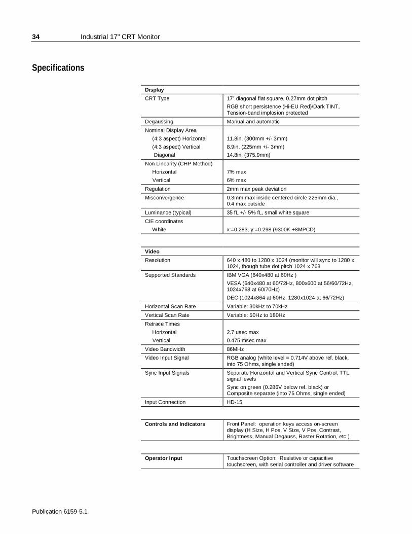
Display
CRT Type 17” diagonal flat square, 0.27mm dot pitch
RGB short persistence (Hi-EU Red)/Dark TINT,Tension-band implosion protected
Degaussing Manual and automatic
Nominal Display Area
(4:3 aspect) Horizontal
(4:3 aspect) Vertical
Diagonal
11.8in. (300mm +/- 3mm)
8.9in. (225mm +/- 3mm)
14.8in. (375.9mm)
Non Linearity (CHP Method)
Horizontal
Vertical
7% max
6% max
Regulation 2mm max peak deviation
Misconvergence 0.3mm max inside centered circle 225mm dia.,0.4 max outside
Luminance (typical) 35 fL +/- 5% fL, small white square
CIE coordinates
White x:=0.283, y:=0.298 (9300K +8MPCD)
Video
Resolution 640 x 480 to 1280 x 1024 (monitor will sync to 1280 x1024, though tube dot pitch 1024 x 768
Supported Standards IBM VGA (640x480 at 60Hz )
VESA (640x480 at 60/72Hz, 800x600 at 56/60/72Hz,1024x768 at 60/70Hz)
DEC (1024x864 at 60Hz, 1280x1024 at 66/72Hz)
Horizontal Scan Rate Variable: 30kHz to 70kHz
Vertical Scan Rate Variable: 50Hz to 180Hz
Retrace Times
Horizontal
Vertical
2.7 usec max
0.475 msec max
Video Bandwidth 86MHz
Video Input Signal RGB analog (white level = 0.714V above ref. black,into 75 Ohms, single ended)
Sync Input Signals Separate Horizontal and Vertical Sync Control, TTLsignal levels
Sync on green (0.286V below ref. black) orComposite separate (into 75 Ohms, single ended)
Input Connection HD-15
Controls and Indicators Front Panel: operation keys access on-screendisplay (H Size, H Pos, V Size, V Pos, Contrast,Brightness, Manual Degauss, Raster Rotation, etc.)
Operator Input Touchscreen Option: Resistive or capacitivetouchscreen, with serial controller and driver software
Industrial 17" CRT Monitor 35
Publication 6159-5.1
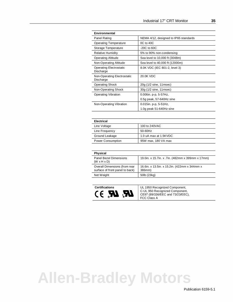
Environmental
Panel Rating NEMA 4/12, designed to IP65 standards
Operating Temperature 0C to 40C
Storage Temperature -20C to 60C
Relative Humidity 5% to 90% non-condensing
Operating Altitude Sea level to 10,000 ft (3048m)
Non-Operating Altitude Sea level to 40,000 ft (12000m)
Operating ElectrostaticDischarge
8.0K VDC (IEC 801-2, level 3)
Non-Operating ElectrostaticDischarge
20.0K VDC
Operating Shock 20g (1/2 sine, 11msec)
Non-Operating Shock 30g (1/2 sine, 11msec)
Operating Vibration 0.006in. p-p, 5-57Hz,
0.5g peak, 57-640Hz sine
Non-Operating Vibration 0.015in. p-p, 5-51Hz,
1.0g peak 51-640Hz sine
Electrical
Line Voltage 100 to 240VAC
Line Frequency 50-60Hz
Ground Leakage 1.0 uA max at 1.5KVDC
Power Consumption 95W max, 180 VA max
Physical
Panel Bezel Dimensions(W x H x D)
19.0in. x 15.7in. x .7in. (482mm x 399mm x 17mm)
Overall Dimensions (from rearsurface of front panel to back)
16.6in. x 13.5in. x 15.2in. (422mm x 344mm x386mm)
Net Weight 50lb (23kg)
Certifications
UL 1950 Recognized Component,C-UL 950 Recognized Component,CE97 (89/336/EEC and 73/23/EEC),FCC Class A
Allen-Bradley Motors

Publication 6159-5.1998060-010
Copyright 1999 Rockwell Automation Corporation. All rights reserved. Printed in USA.
IBM is a registered trademark of International Business Machines Corporation.
VGA is a trademark of International Business Machines Corporation.
PC AT is a trademark of International Business Machines Corporation.
Microsoft is a registered trademark of Microsoft Corporation.
Microsoft Windows is a trademark of Microsoft Corporation.
Rockwell Automation helps its customers receive a superior return on their investment by bringingtogether leading brands in industrial automation, creating a broad spectrum of easy-to-integrateproducts. These are supported by local technical resources available worldwide, a global network ofsystem solutions providers, and the advanced technology resources of Rockwell.
Worldwide representation.
Argentina • Australia • Austria • Bahrain • Belgium • Bolivia • Brazil • Bulgaria • Canada • Chile • China, People’s Republic of • Colombia • Costa Rica • Croatia • Cyprus • CzechRepublic • Denmark • Dominican Republic • Ecuador • Egypt • El Salvador • Finland • France • Germany • Ghana • Greece • Guatemala • Honduras • Hong Kong • Hungary •Iceland • India • Indonesia • Iran • Ireland • Israel • Italy • Jamaica • Japan • Jordan • Korea • Kuwait • Lebanon • Macau • Malaysia • Malta • Mexico • Morocco • The Netherlands •New Zealand • Nigeria • Norway • Oman • Pakistan • Panama • Peru • Philippines • Poland • Portugal • Puerto Rico • Qatar • Romania • Russia • Saudi Arabia • Singapore •Slovakia • Slovenia • South Africa, Republic of • Spain • Sweden • Switzerland • Taiwan • Thailand • Trinidad • Tunisia • Turkey • United Arab Emirates • United Kingdom • UnitedStates • Uruguay • Venezuela
Rockwell Automation Headquarters, 1201 South Second Street, Milwaukee, WI 53204-2496 USA, Tel: (1) 414 382-2000, Fax: (1) 414 382-4444Rockwell Automation European Headquarters, Avenue Hermann Debroux, 46 1160 Brussels, Belgium, Tel: (32) 2 663 06 00, Fax: (32) 2 663 06 40Rockwell Automation Asia Pacific Headquarters, 27/F Citicorp Centre, 18 Whitfield Road, Causeway Bay, Hong Kong, Tel: (852) 2887 4788, Fax: (852) 2508 1846World Wide Web: http://www.ab.com