6.0l features book 2003.25
TRANSCRIPT
F O R WA R DThis publication is intended to provide technicians and service personnel with an overview of technical advancements in the6.0L POWER STROKE Diesel Engine. The information contained in this publication will supplement information contained inavailable service literature.
I M P O R TA N T S A F E T Y N O T I C EAppropriate service methods and proper repair procedures are essential for the safe,reliable operation of all motor vehicles, as well as, the personal safety of the individualperforming the work. This manual provides general directions for accomplishing servicerepair work with tested, effective techniques. Following the directions will assure reliability. There are numerous variations in the procedures; techniques, tools, parts forservicing vehicles and the skill of the individual doing the work. This manual cannot possibly anticipate all such variations and provide advice or cautions as to each.Accordingly, anyone who departs from the instructions provided in this manual must firstestablish that they do not compromise their personal safety or the vehicle integrity bytheir choice of methods, tools or parts.
The following list contains some general WARNINGS that you should follow when youwork on a vehicle.
Always wear safety glasses for eye protection.
Use safety stands whenever a procedure requires you to be under the vehicle.
Be sure that the ignition switch is always in the OFF position, unless otherwise requiredby the procedure.
Never perform any service to the engine with the air cleaner removed and the enginerunning unless a turbocharger compressor inlet shield is installed.
Set the parking brake when working on the vehicle. If you have an automatic transmission, set it in PARK unless instructed otherwise for a specific service operation.If you have a manual transmission, it should be in REVERSE (engine OFF) or NEUTRAL (engine ON) unless instructed otherwise for a specific service operation.
Operate the engine only in a well-ventilated area to avoid the danger of carbonmonoxide.
Keep yourself and your clothing away from moving parts when the engine is running,especially the fan, belts, and the turbocharger compressor.
To prevent serious burns, avoid contact with hot metal parts such as the radiator, turbocharger pipes, exhaust manifold, tail pipe, catalytic converter and muffler.
Do not smoke while working on the vehicle.
To avoid injury, always remove rings, watches, loose hanging jewelry, and loose clothingbefore beginning to work on a vehicle. Tie long hair securely behind the head.
Keep hands and other objects clear of the radiator fan blades.

This page intent ional lyleft blank
6 . 0 L P O W E R S T R O K E
3
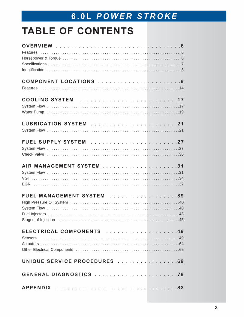
TABLE OF CONTENTSOVERVIEW . . . . . . . . . . . . . . . . . . . . . . . . . . . . . . . . .6Features . . . . . . . . . . . . . . . . . . . . . . . . . . . . . . . . . . . . . . . . . . . . . . . . . . . . . . . . . . . . . . . .6
Horsepower & Torque . . . . . . . . . . . . . . . . . . . . . . . . . . . . . . . . . . . . . . . . . . . . . . . . . . . . . .6
Specifications . . . . . . . . . . . . . . . . . . . . . . . . . . . . . . . . . . . . . . . . . . . . . . . . . . . . . . . . . . . .7
Identification . . . . . . . . . . . . . . . . . . . . . . . . . . . . . . . . . . . . . . . . . . . . . . . . . . . . . . . . . . . . .8
COMPONENT LOCATIONS . . . . . . . . . . . . . . . . . . . . . .9Features . . . . . . . . . . . . . . . . . . . . . . . . . . . . . . . . . . . . . . . . . . . . . . . . . . . . . . . . . . . . . . .14
COOLING SYSTEM . . . . . . . . . . . . . . . . . . . . . . . . . .17System Flow . . . . . . . . . . . . . . . . . . . . . . . . . . . . . . . . . . . . . . . . . . . . . . . . . . . . . . . . . . . .17
Water Pump . . . . . . . . . . . . . . . . . . . . . . . . . . . . . . . . . . . . . . . . . . . . . . . . . . . . . . . . . . . .19
LUBRICATION SYSTEM . . . . . . . . . . . . . . . . . . . . . . .21System Flow . . . . . . . . . . . . . . . . . . . . . . . . . . . . . . . . . . . . . . . . . . . . . . . . . . . . . . . . . . . .21
FUEL SUPPLY SYSTEM . . . . . . . . . . . . . . . . . . . . . . .27System Flow . . . . . . . . . . . . . . . . . . . . . . . . . . . . . . . . . . . . . . . . . . . . . . . . . . . . . . . . . . . .27
Check Valve . . . . . . . . . . . . . . . . . . . . . . . . . . . . . . . . . . . . . . . . . . . . . . . . . . . . . . . . . . . .30
AIR MANAGEMENT SYSTEM . . . . . . . . . . . . . . . . . . . .31System Flow . . . . . . . . . . . . . . . . . . . . . . . . . . . . . . . . . . . . . . . . . . . . . . . . . . . . . . . . . . . .31
VGT . . . . . . . . . . . . . . . . . . . . . . . . . . . . . . . . . . . . . . . . . . . . . . . . . . . . . . . . . . . . . . . . . . .34
EGR . . . . . . . . . . . . . . . . . . . . . . . . . . . . . . . . . . . . . . . . . . . . . . . . . . . . . . . . . . . . . . . . . .37
FUEL MANAGEMENT SYSTEM . . . . . . . . . . . . . . . . . .39High Pressure Oil System . . . . . . . . . . . . . . . . . . . . . . . . . . . . . . . . . . . . . . . . . . . . . . . . . .40
System Flow . . . . . . . . . . . . . . . . . . . . . . . . . . . . . . . . . . . . . . . . . . . . . . . . . . . . . . . . . . . .40
Fuel Injectors . . . . . . . . . . . . . . . . . . . . . . . . . . . . . . . . . . . . . . . . . . . . . . . . . . . . . . . . . . . .43
Stages of Injection . . . . . . . . . . . . . . . . . . . . . . . . . . . . . . . . . . . . . . . . . . . . . . . . . . . . . . .45
ELECTRICAL COMPONENTS . . . . . . . . . . . . . . . . . . .49Sensors . . . . . . . . . . . . . . . . . . . . . . . . . . . . . . . . . . . . . . . . . . . . . . . . . . . . . . . . . . . . . . . .49
Actuators . . . . . . . . . . . . . . . . . . . . . . . . . . . . . . . . . . . . . . . . . . . . . . . . . . . . . . . . . . . . . . .64
Other Electrical Components . . . . . . . . . . . . . . . . . . . . . . . . . . . . . . . . . . . . . . . . . . . . . . .65
UNIQUE SERVICE PROCEDURES . . . . . . . . . . . . . . . .69
GENERAL DIAGNOSTICS . . . . . . . . . . . . . . . . . . . . . .79
APPENDIX . . . . . . . . . . . . . . . . . . . . . . . . . . . . . . . .83

This page intent ional lyleft blank
1
D irect In ject ionTurbocharged Diesel
Engine
6.0L Power Stroke
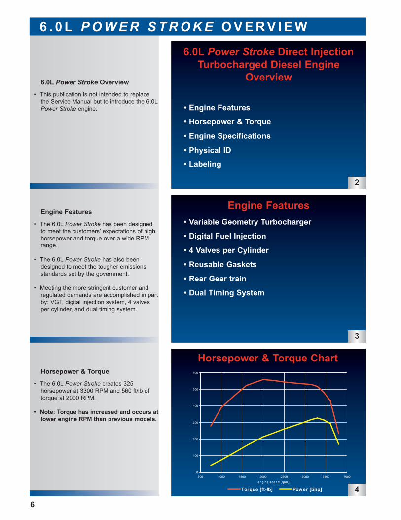
• The 6.0L Power Stroke creates 325 horsepower at 3300 RPM and 560 ft/lb oftorque at 2000 RPM.
• Note: Torque has increased and occurs atlower engine RPM than previous models.
• This publication is not intended to replacethe Service Manual but to introduce the 6.0LPower Stroke engine.
Horsepower & Torque
Engine Features
6.0L Power Stroke Overview
6 . 0 L P O W E R S T R O K E O V E R V I E W
6.0L Power Stroke Direct InjectionTurbocharged Diesel Engine
Overview
• Engine Features
• Horsepower & Torque
• Engine Specifications
• Physical ID
• Labeling
2
Engine Features • Variable Geometry Turbocharger
• Digital Fuel Injection
• 4 Valves per Cylinder
• Reusable Gaskets
• Rear Gear train
• Dual Timing System
3
6
• The 6.0L Power Stroke has been designedto meet the customers’ expectations of highhorsepower and torque over a wide RPMrange.
• The 6.0L Power Stroke has also beendesigned to meet the tougher emissionsstandards set by the government.
• Meeting the more stringent customer andregulated demands are accomplished in partby: VGT, digital injection system, 4 valvesper cylinder, and dual timing system.
0
100
200
300
400
500
600
500 1000 1500 2000 2500 3000 3500 4000
engine speed [rpm]
Torque [ft-lb] Power [bhp] 4
Horsepower & Torque Chart
6 . 0 L P O W E R S T R O K E O V E R V I E W
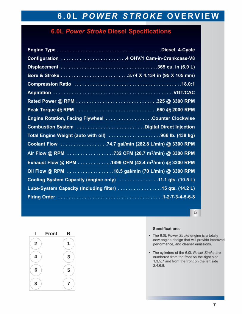
6.0L Power Stroke Diesel Specifications
Engine Type . . . . . . . . . . . . . . . . . . . . . . . . . . . . . . . . . . . . . . . .Diesel, 4-Cycle
Configuration . . . . . . . . . . . . . . . . . . . . . . . . .4 OHV/1 Cam-in-Crankcase-V8
Displacement . . . . . . . . . . . . . . . . . . . . . . . . . . . . . . . . . . . . .365 cu. in (6.0 L)
Bore & Stroke . . . . . . . . . . . . . . . . . . . . . . . . . .3.74 X 4.134 in (95 X 105 mm)
Compression Ratio . . . . . . . . . . . . . . . . . . . . . . . . . . . . . . . . . . . . . . . . .18.0:1
Aspiration . . . . . . . . . . . . . . . . . . . . . . . . . . . . . . . . . . . . . . . . . . . . . .VGT/CAC
Rated Power @ RPM . . . . . . . . . . . . . . . . . . . . . . . . . . . . . . .325 @ 3300 RPM
Peak Torque @ RPM . . . . . . . . . . . . . . . . . . . . . . . . . . . . . . .560 @ 2000 RPM
Engine Rotation, Facing Flywheel . . . . . . . . . . . . . . . . . .Counter Clockwise
Combustion System . . . . . . . . . . . . . . . . . . . . . . . . . .Digital Direct Injection
Total Engine Weight (auto with oil) . . . . . . . . . . . . . . . . . . . .966 lb. (438 kg)
Coolant Flow . . . . . . . . . . . . . . . . . .74.7 gal/min (282.8 L/min) @ 3300 RPM
Air Flow @ RPM . . . . . . . . . . . . . . . . . .732 CFM (20.7 m3/min) @ 3300 RPM
Exhaust Flow @ RPM . . . . . . . . . . . . .1499 CFM (42.4 m3/min) @ 3300 RPM
Oil Flow @ RPM . . . . . . . . . . . . . . . . . .18.5 gal/min (70 L/min) @ 3300 RPM
Cooling System Capacity (engine only) . . . . . . . . . . . . . . .11.1 qts. (10.5 L)
Lube-System Capacity (including filter) . . . . . . . . . . . . . . . . .15 qts. (14.2 L)
Firing Order . . . . . . . . . . . . . . . . . . . . . . . . . . . . . . . . . . . . . . . .1-2-7-3-4-5-6-8
2
8
4
6
7
5
3
1
FrontL R
5
7
• The 6.0L Power Stroke engine is a totallynew engine design that will provide improved performance, and cleaner emissions.
• The cylinders of the 6.0L Power Stroke arenumbered from the front on the right side1,3,5,7 and from the front on the left side2,4,6,8.
Specifications
6
7
8
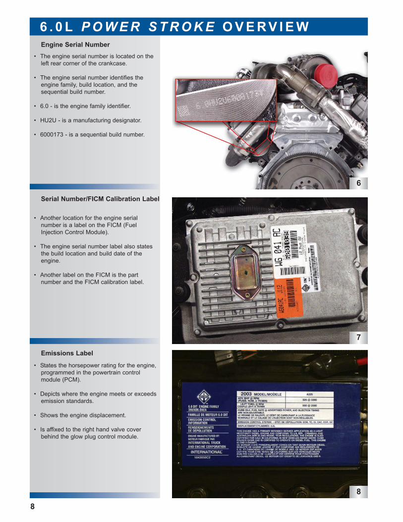
• Another location for the engine serial number is a label on the FICM (FuelInjection Control Module).
• The engine serial number label also statesthe build location and build date of theengine.
• Another label on the FICM is the part number and the FICM calibration label.
Emissions Label
Serial Number/FICM Calibration Label
Engine Serial Number
6 . 0 L P O W E R S T R O K E O V E R V I E W
8
• The engine serial number is located on theleft rear corner of the crankcase.
• The engine serial number identifies theengine family, build location, and thesequential build number.
• 6.0 - is the engine family identifier.
• HU2U - is a manufacturing designator.
• 6000173 - is a sequential build number.
• States the horsepower rating for the engine,programmed in the powertrain control module (PCM).
• Depicts where the engine meets or exceedsemission standards.
• Shows the engine displacement.
• Is affixed to the right hand valve coverbehind the glow plug control module.
9
10
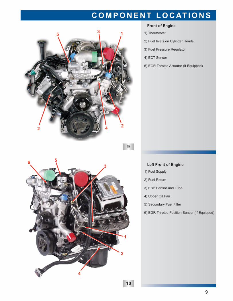
1) Fuel Supply
2) Fuel Return
3) EBP Sensor and Tube
4) Upper Oil Pan
5) Secondary Fuel Filter
6) EGR Throttle Position Sensor (If Equipped)
1) Thermostat
2) Fuel Inlets on Cylinder Heads
3) Fuel Pressure Regulator
4) ECT Sensor
5) EGR Throttle Actuator (If Equipped)
Left Front of Engine
Front of Engine
C O M P O N E N T L O C AT I O N S
9
1
2 2
35
4
1
2
3
4
56
11
12
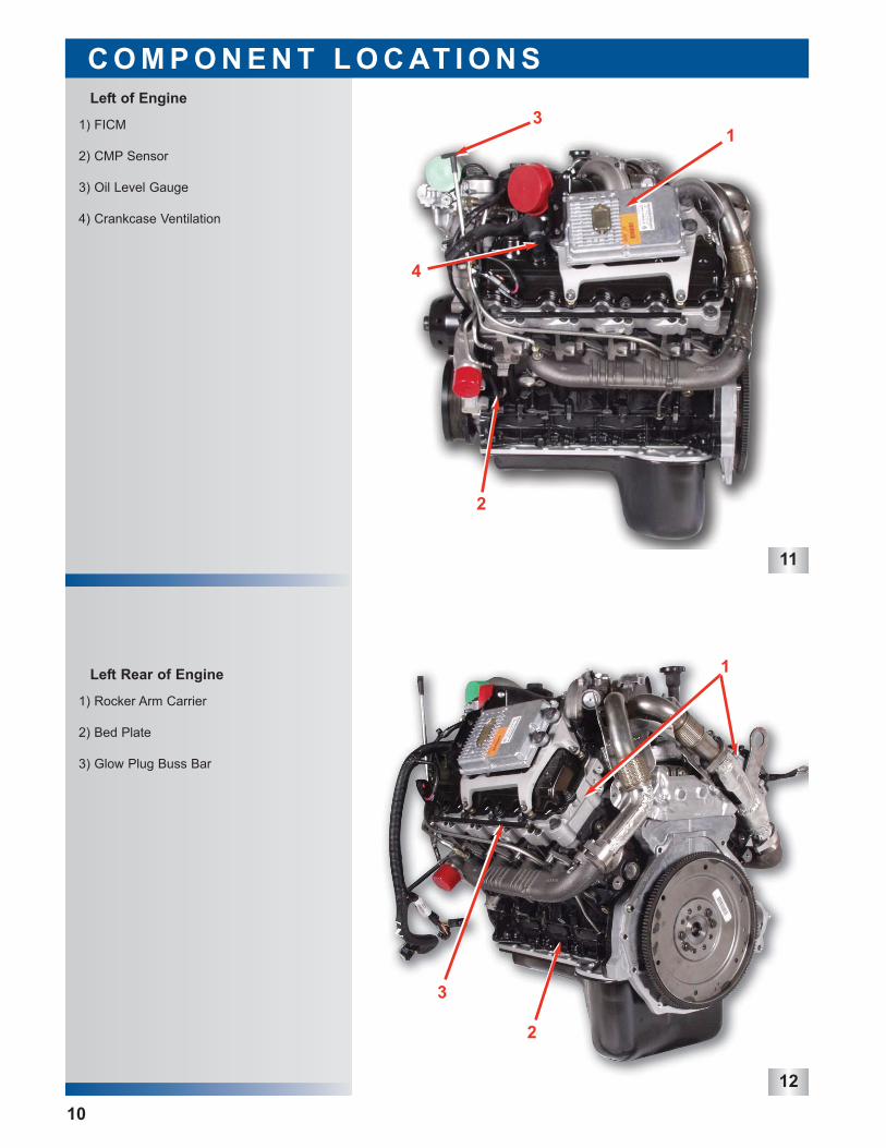
1) Rocker Arm Carrier
2) Bed Plate
3) Glow Plug Buss Bar
1) FICM
2) CMP Sensor
3) Oil Level Gauge
4) Crankcase Ventilation
Left Rear of Engine
Left of Engine
C O M P O N E N T L O C AT I O N S
10
1
3
2
13
4
2
13
14
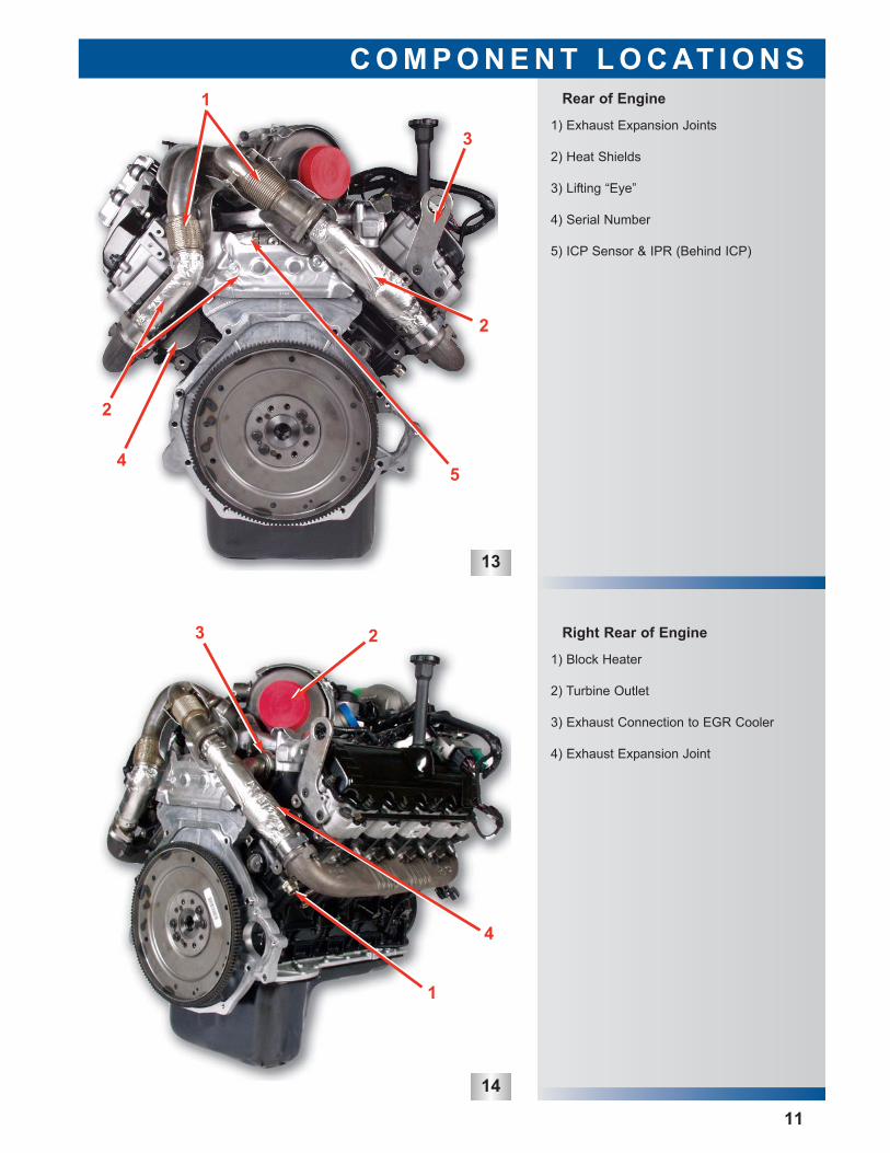
Right Rear of Engine
1) Block Heater
2) Turbine Outlet
3) Exhaust Connection to EGR Cooler
4) Exhaust Expansion Joint
1) Exhaust Expansion Joints
2) Heat Shields
3) Lifting “Eye”
4) Serial Number
5) ICP Sensor & IPR (Behind ICP)
Rear of Engine
C O M P O N E N T L O C AT I O N S
11
1
2
2
3
4
1
3 2
5
4
15
16
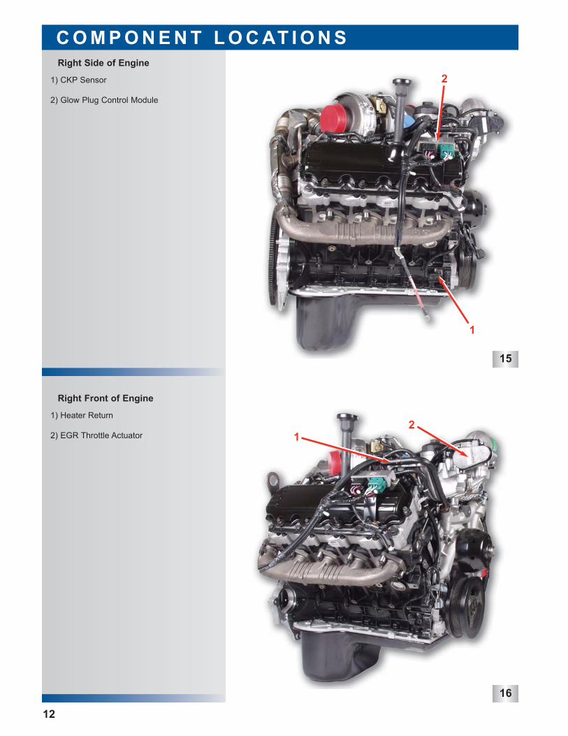
1) Heater Return
2) EGR Throttle Actuator
1) CKP Sensor
2) Glow Plug Control Module
Right Front of Engine
Right Side of Engine
C O M P O N E N T L O C AT I O N S
12
12
1
2
17
18
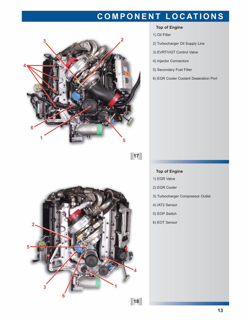
Top of Engine
1) EGR Valve
2) EGR Cooler
3) Turbocharger Compressor Outlet
4) IAT2 Sensor
5) EOP Switch
6) EOT Sensor
1) Oil Filter
2) Turbocharger Oil Supply Line
3) EVRT/VGT Control Valve
4) Injector Connectors
5) Secondary Fuel Filter
6) EGR Cooler Coolant Deaeration Port
Top of Engine
C O M P O N E N T L O C AT I O N S
13
1
6
5
23
4
2
3
4
6
5
1
19
20
21
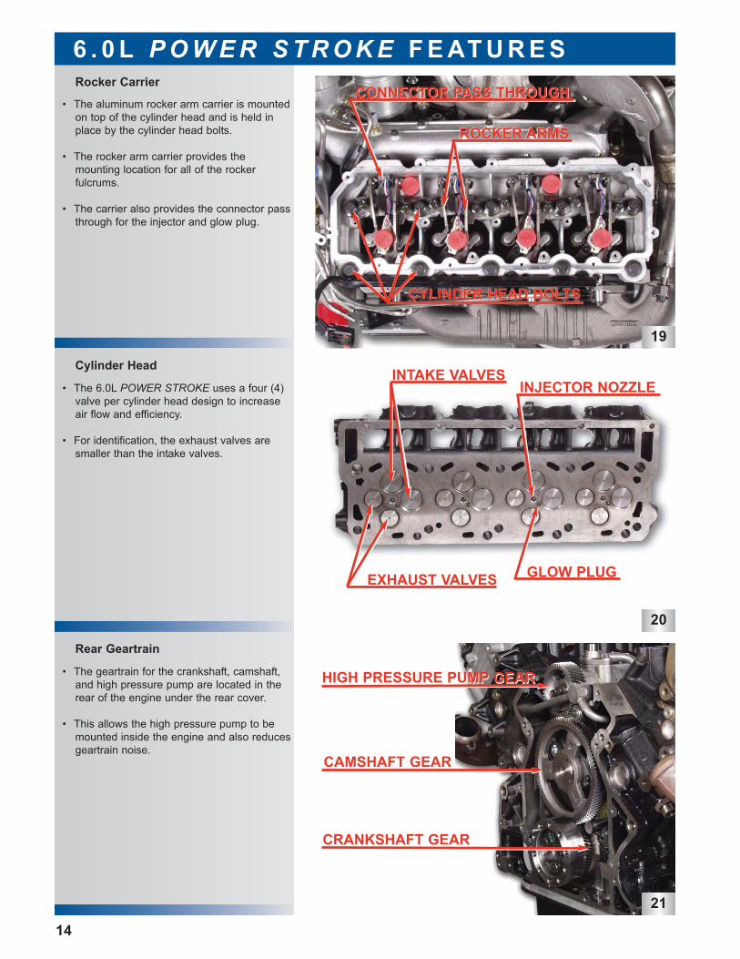
• The geartrain for the crankshaft, camshaft,and high pressure pump are located in therear of the engine under the rear cover.
• This allows the high pressure pump to bemounted inside the engine and also reducesgeartrain noise.
Rear Geartrain
Cylinder Head
Rocker Carrier
6 . 0 L P O W E R S T R O K E F E AT U R E S
14
• The aluminum rocker arm carrier is mountedon top of the cylinder head and is held inplace by the cylinder head bolts.
• The rocker arm carrier provides the mounting location for all of the rocker fulcrums.
• The carrier also provides the connector passthrough for the injector and glow plug.
• The 6.0L POWER STROKE uses a four (4)valve per cylinder head design to increaseair flow and efficiency.
• For identification, the exhaust valves aresmaller than the intake valves.
CONNECTOR PASS THROUGHCONNECTOR PASS THROUGH
CYLINDER HEAD BOLTSCYLINDER HEAD BOLTS
ROCKER ARMSROCKER ARMS
EXHAUST VALVES
INTAKE VALVESINJECTOR NOZZLE
GLOW PLUG
HIGH PRESSURE PUMP GEARHIGH PRESSURE PUMP GEAR
CAMSHAFT GEAR
CRANKSHAFT GEAR
22
23
24
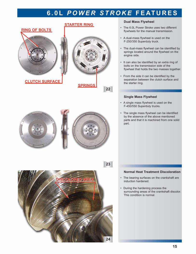
Normal Heat Treatment Discoloration
• The bearing surfaces on the crankshaft areinduction hardened.
• During the hardening process the surrounding areas of the crankshaft discolor.This condition is normal.
• A single mass flywheel is used on the F-450/550 Superduty trucks.
• The single mass flywheel can be identifiedby the absence of the above mentionedparts and that it is machined from one solidpart.
• The 6.0L Power Stroke uses two different flywheels for the manual transmission.
• A dual-mass flywheel is used on the F-250/350 Superduty truck.
• The dual-mass flywheel can be identified bysprings located around the flywheel on theengine side.
• It can also be identified by an extra ring ofbolts on the transmission side of the flywheel that holds the two masses together.
• From the side it can be identified by the separation between the clutch surface andthe starter ring.
Single Mass Flywheel
Dual Mass Flywheel
6 . 0 L P O W E R S T R O K E F E AT U R E S
15
RING OF BOLTS
CLUTCH SURFACE
STARTER RING
SPRINGS
DISCOLORED AREADISCOLORED AREA

16
This page intent ional lyleft blank
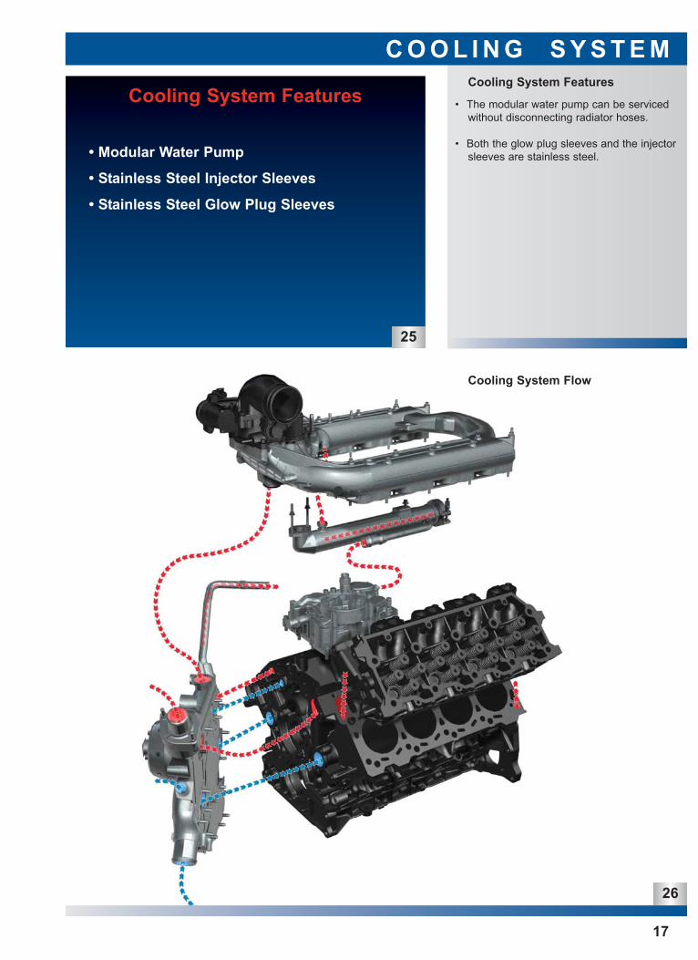
• The modular water pump can be servicedwithout disconnecting radiator hoses.
• Both the glow plug sleeves and the injectorsleeves are stainless steel.
Cooling System Features
C O O L I N G S Y S T E M
Cooling System Flow
Cooling System Features
• Modular Water Pump
• Stainless Steel Injector Sleeves
• Stainless Steel Glow Plug Sleeves
25
17
26
27
28
29
Cooling System Flow: Oil Cooler
Cooling System Flow: Back of FrontCover
Cooling System Flow: Front Cover
C O O L I N G S Y S T E M
18
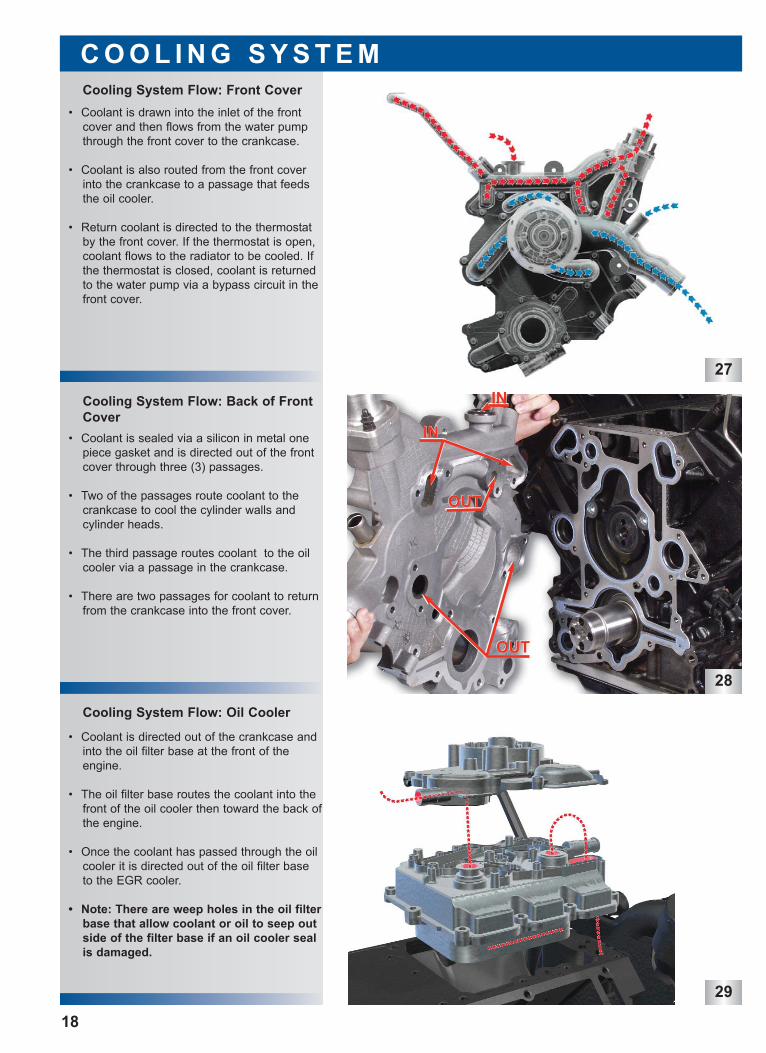
• Coolant is drawn into the inlet of the frontcover and then flows from the water pumpthrough the front cover to the crankcase.
• Coolant is also routed from the front coverinto the crankcase to a passage that feedsthe oil cooler.
• Return coolant is directed to the thermostatby the front cover. If the thermostat is open,coolant flows to the radiator to be cooled. Ifthe thermostat is closed, coolant is returnedto the water pump via a bypass circuit in thefront cover.
• Coolant is sealed via a silicon in metal onepiece gasket and is directed out of the frontcover through three (3) passages.
• Two of the passages route coolant to thecrankcase to cool the cylinder walls andcylinder heads.
• The third passage routes coolant to the oilcooler via a passage in the crankcase.
• There are two passages for coolant to returnfrom the crankcase into the front cover.
• Coolant is directed out of the crankcase andinto the oil filter base at the front of theengine.
• The oil filter base routes the coolant into thefront of the oil cooler then toward the back ofthe engine.
• Once the coolant has passed through the oilcooler it is directed out of the oil filter baseto the EGR cooler.
• Note: There are weep holes in the oil filterbase that allow coolant or oil to seep outside of the filter base if an oil cooler sealis damaged.
ININ
ININ
OUTOUT
OUTOUT
30
31
32
Injector Sleeve
Water Pump & Front Cover
Cooling System Flow: EGR Cooler
C O O L I N G S Y S T E M
19
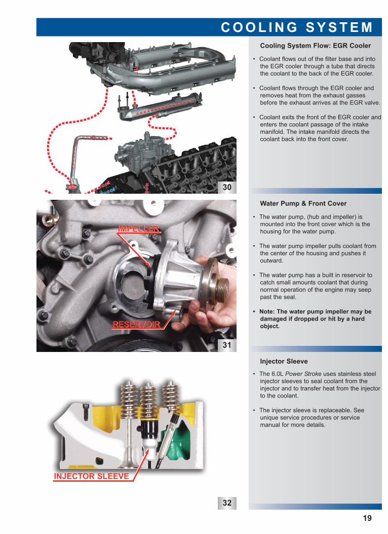
• Coolant flows out of the filter base and intothe EGR cooler through a tube that directsthe coolant to the back of the EGR cooler.
• Coolant flows through the EGR cooler andremoves heat from the exhaust gassesbefore the exhaust arrives at the EGR valve.
• Coolant exits the front of the EGR cooler andenters the coolant passage of the intakemanifold. The intake manifold directs thecoolant back into the front cover.
• The water pump, (hub and impeller) ismounted into the front cover which is thehousing for the water pump.
• The water pump impeller pulls coolant fromthe center of the housing and pushes it outward.
• The water pump has a built in reservoir tocatch small amounts coolant that during normal operation of the engine may seeppast the seal.
• Note: The water pump impeller may bedamaged if dropped or hit by a hardobject.
• The 6.0L Power Stroke uses stainless steelinjector sleeves to seal coolant from the injector and to transfer heat from the injectorto the coolant.
• The injector sleeve is replaceable. Seeunique service procedures or service manual for more details.
IMPELLERIMPELLER
RESERVOIRRESERVOIR
INJECTOR SLEEVEINJECTOR SLEEVE
33
34
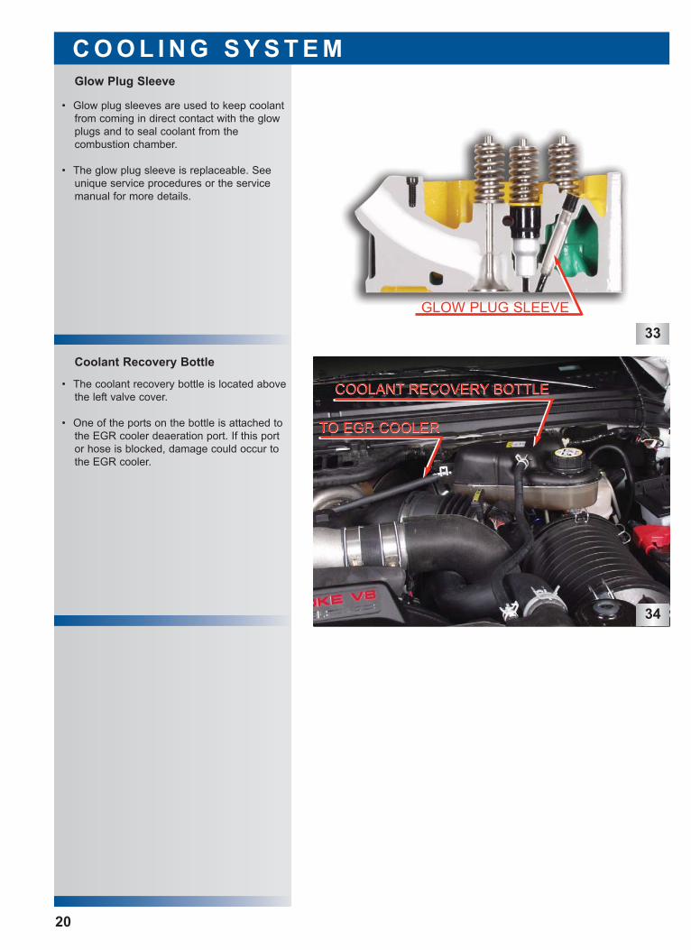
• The coolant recovery bottle is located abovethe left valve cover.
• One of the ports on the bottle is attached tothe EGR cooler deaeration port. If this portor hose is blocked, damage could occur tothe EGR cooler.
Coolant Recovery Bottle
Glow Plug Sleeve
C O O L I N G S Y S T E M
20
• Glow plug sleeves are used to keep coolantfrom coming in direct contact with the glowplugs and to seal coolant from the combustion chamber.
• The glow plug sleeve is replaceable. Seeunique service procedures or the servicemanual for more details.
GLOW PLUG SLEEVEGLOW PLUG SLEEVE
COOLANT RECOVERY BOTTLECOOLANT RECOVERY BOTTLE
TO EGR COOLERTO EGR COOLER
36
System Flow
Lubrication System Features
L U B R I C AT I O N S Y S T E M
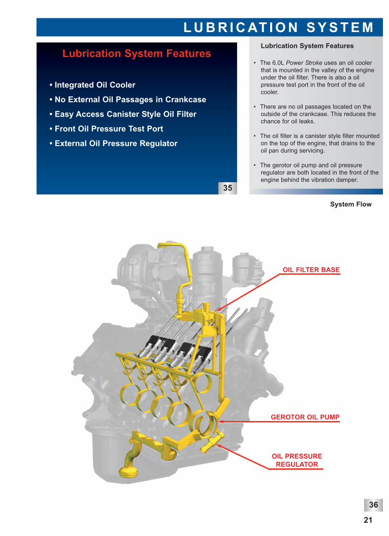
• The 6.0L Power Stroke uses an oil coolerthat is mounted in the valley of the engineunder the oil filter. There is also a oil pressure test port in the front of the oil cooler.
• There are no oil passages located on theoutside of the crankcase. This reduces thechance for oil leaks.
• The oil filter is a canister style filter mountedon the top of the engine, that drains to theoil pan during servicing.
• The gerotor oil pump and oil pressure regulator are both located in the front of theengine behind the vibration damper.
Lubrication System Features
• Integrated Oil Cooler
• No External Oil Passages in Crankcase
• Easy Access Canister Style Oil Filter
• Front Oil Pressure Test Port
• External Oil Pressure Regulator
35
21
OIL FILTER BASE
GEROTOR OIL PUMP
OIL PRESSUREREGULATOR
Oil Pump
Oil
Co
ole
r
Oil Filter
PumpBypass70 PSI
CoolerBypass25 PSI
FilterBypass20 PSI
Lube Pressure Oil System Schematic
T
T
T
T
T
T
T
T
T
T
T
T
T
T T
T
MB
MB
MB
MB
MB
CB
CB
CB
CB
CB
Turbo
CR
CR
CR
CR
CR
CR
CR
CR
Oil Reservoirfor HighPressure
Pump 0.95 Qt.
To HighPressure Oil
System
T= TappetCB = Cam BearingMB = Main Bearing
CR= Connecting Rod= Piston Cooling Jet
Right Bank Left Bank
37
38
Oil Pan / Bed Plate
Lubrication System Oil Flow
L U B R I C AT I O N S Y S T E M
22
• Oil is drawn from the oil pan through thepick-up tube to the gerotor oil pump.
• The oil pressure is regulated to 75 psi viathe oil pressure regulator relieving excessiveoil pressure to the inlet of the oil pump.
• From the oil pump, oil is directed to the oilcooler and then the to the oil filter.
• From the oil filter the oil is supplied to four(4) passages. One is to the turbocharger forlubrication and VGT control via an externalline.
• The oil also is provided to the oil reservoirthat supplies the high pressure oil pump.
• The two (2) other passages are to the tappetoil feed on the right and left banks. The tappet galleries also provide oil to the pistoncooling jets.
• Cross drillings off of the right bank tappetgallery feed the cam bearings, then thecrankshaft main bearings.
• The crankshaft has cross drillings in it todirect oil to each of connecting rod bearings.
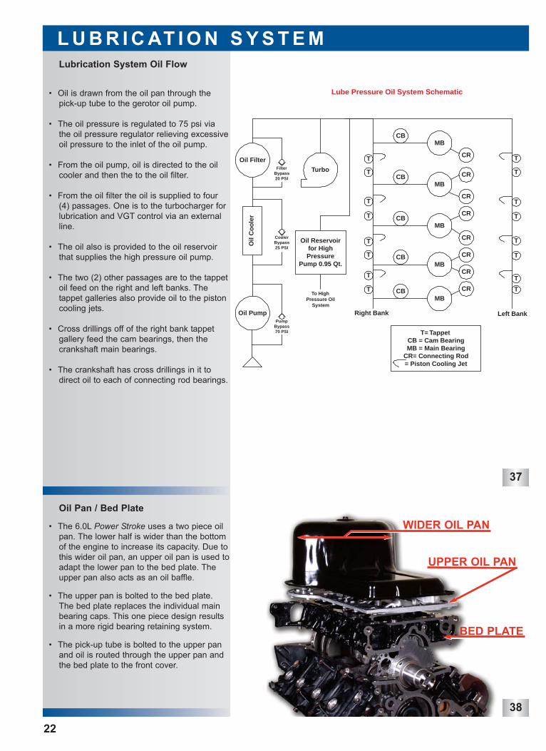
• The 6.0L Power Stroke uses a two piece oilpan. The lower half is wider than the bottomof the engine to increase its capacity. Due tothis wider oil pan, an upper oil pan is used toadapt the lower pan to the bed plate. Theupper pan also acts as an oil baffle.
• The upper pan is bolted to the bed plate.The bed plate replaces the individual mainbearing caps. This one piece design resultsin a more rigid bearing retaining system.
• The pick-up tube is bolted to the upper panand oil is routed through the upper pan andthe bed plate to the front cover.
WIDER OIL PAN
UPPER OIL PAN
BED PLATE
39
40
41
Gerotor Oil Pump
Oil Pressure Regulator
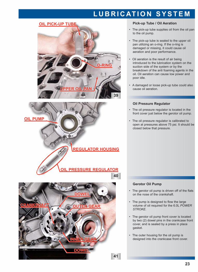
Pick-up Tube / Oil Aeration
L U B R I C AT I O N S Y S T E M
23
• The pick-up tube supplies oil from the oil panto the oil pump.
• The pick-up tube is sealed to the upper oilpan utilizing an o-ring. If the o-ring is damaged or missing, it could cause oil aeration and poor performance.
• Oil aeration is the result of air being introduced to the lubrication system on the suction side of the system or by the breakdown of the anti foaming agents in theoil. Oil aeration can cause low power andpoor idle.
• A damaged or loose pick-up tube could alsocause oil aeration.
• The oil pressure regulator is located in thefront cover just below the gerotor oil pump.
• The oil pressure regulator is calibrated toopen at pressures above 75 psi. It should beclosed below that pressure.
• The gerotor oil pump is driven off of the flatson the nose of the crankshaft.
• The pump is designed to flow the large volume of oil required for the 6.0L POWERSTROKE.
• The gerotor oil pump front cover is locatedby two (2) dowel pins in the crankcase frontcover, and is sealed by a press in place gasket.
• The outer housing for the oil pump isdesigned into the crankcase front cover.
O-RINGO-RING
UPPER OIL PANUPPER OIL PAN
OIL PICK-UP TUBEOIL PICK-UP TUBE
OIL PUMPOIL PUMP
OIL PRESSURE REGULATOR
REGULATOR HOUSING
DOWELDOWEL
DOWELDOWEL
OUTER GEAROUTER GEAR
INNER GEARINNER GEAR
CRANKSHAFTCRANKSHAFT
42
43
44
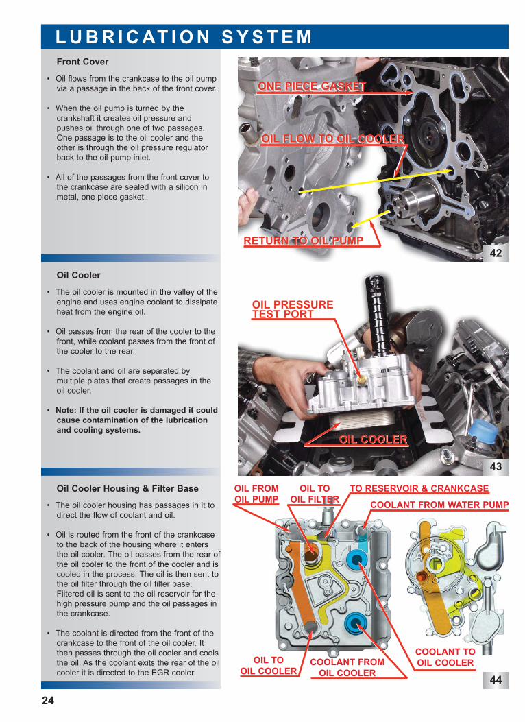
Oil Cooler Housing & Filter Base
Oil Cooler
Front Cover
L U B R I C AT I O N S Y S T E M
24
• Oil flows from the crankcase to the oil pumpvia a passage in the back of the front cover.
• When the oil pump is turned by the crankshaft it creates oil pressure and pushes oil through one of two passages.One passage is to the oil cooler and theother is through the oil pressure regulatorback to the oil pump inlet.
• All of the passages from the front cover tothe crankcase are sealed with a silicon inmetal, one piece gasket.
• The oil cooler is mounted in the valley of theengine and uses engine coolant to dissipateheat from the engine oil.
• Oil passes from the rear of the cooler to thefront, while coolant passes from the front ofthe cooler to the rear.
• The coolant and oil are separated by multiple plates that create passages in theoil cooler.
• Note: If the oil cooler is damaged it couldcause contamination of the lubricationand cooling systems.
• The oil cooler housing has passages in it todirect the flow of coolant and oil.
• Oil is routed from the front of the crankcaseto the back of the housing where it entersthe oil cooler. The oil passes from the rear ofthe oil cooler to the front of the cooler and iscooled in the process. The oil is then sent tothe oil filter through the oil filter base.Filtered oil is sent to the oil reservoir for thehigh pressure pump and the oil passages inthe crankcase.
• The coolant is directed from the front of thecrankcase to the front of the oil cooler. Itthen passes through the oil cooler and coolsthe oil. As the coolant exits the rear of the oilcooler it is directed to the EGR cooler.
RETURN TO OIL PUMPRETURN TO OIL PUMP
OIL FLOW TO OIL COOLEROIL FLOW TO OIL COOLER
ONE PIECE GASKETONE PIECE GASKET
OIL PRESSURE TEST PORT
OIL COOLEROIL COOLER
TO RESERVOIR & CRANKCASE
COOLANT FROM WATER PUMP
COOLANT TOOIL COOLEROIL TO
OIL COOLER
OIL FROMOIL PUMP
COOLANT FROMOIL COOLER
OIL TOOIL FILTER
45
46
47
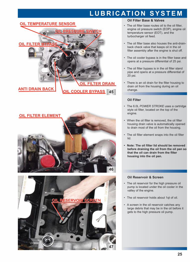
Oil Reservoir & Screen
Oil Filter
Oil Filter Base & ValvesL U B R I C AT I O N S Y S T E M
25
• The oil reservoir for the high pressure oilpump is located under the oil cooler in thevalley of the engine.
• The oil reservoir holds about 1qt of oil.
• A screen in the oil reservoir catches anylarge debris that may be in the oil before itgets to the high pressure oil pump.
• The 6.0L POWER STROKE uses a cartridgestyle oil filter, located on the top of theengine.
• When the oil filter is removed, the oil filterhousing drain valve is automatically openedto drain most of the oil from the housing.
• The oil filter element snaps into the oil filterlid.
• Note: The oil filter lid should be removedbefore draining the oil from the oil pan sothat the oil can drain from the filter housing into the oil pan.
• The oil filter base routes oil to the oil filter,engine oil pressure switch (EOP), engine oiltemperature sensor (EOT), and the turbocharger oil feed.
• The oil filter base also houses the anti-drain-back check valve that keeps oil in the oil filter assembly after the engine is shut off.
• The oil cooler bypass is in the filter base andopens at a pressure differential of 25 psi.
• The oil filter bypass is in the oil filter standpipe and opens at a pressure differential of20 psi.
• There is an oil drain for the filter housing todrain oil from the housing during an oilchange.
OIL TEMPERATURE SENSOR
OIL PRESSURE SWITCHOIL PRESSURE SWITCH
OIL COOLER BYPASSANTI DRAIN BACKOIL FILTER DRAIN
OIL FILTER BYPASSOIL FILTER BYPASS
OIL FILTER ELEMENT
OIL RESERVOIR SCREENOIL RESERVOIR SCREEN

48
49
50
• The VGT uses oil to control the turbochargerand to lubricate the bearings.
• After oil passes through the turbochargercenter section, it is sent back to thecrankcase via a turbo oil drain tube.
• The turbo oil drain tube is located under theturbocharger and is sealed with two (2) o-rings, one fits into the turbocharger andthe other goes to the high pressure oil pumpcover.
Turbocharger Oil Drain Tube
Turbocharger Oil Supply & VGTControl
Oil Flow at Oil Reservoir
L U B R I C AT I O N S Y S T E M
26
• There are five (5) oil passages and onecoolant passage near the oil reservoir in thecrankcase.
• Two (2) of the oil passages are for oil feed tothe crankcase for lubrication.
• One (1) is for oil feed to the oil cooler andthe other oil passage is oil filter drain to theoil pan.
• The passage in the bottom of the reservoir isfor oil feed to the high pressure oil pump.
• The coolant passage is for coolant feed fromthe water pump to the oil cooler.
• Oil is supplied to the turbocharger from theoil filter base via a flexible steel braided oilline to the top of the turbocharger.
• The oil line is connected to the oil filter baseusing a snap to connect fitting and requiresa special tool for removal.
• This line is also the feed to the VGT controlvalve.
PRESSURE PUMPPRESSURE PUMPOIL FEED TO HIGHOIL FEED TO HIGH
OIL FILTER DRAIN TO PANOIL COOLEROIL FEED TOOIL COOLEROIL FEED TO
BANK TAPPETTO LEFT
GALLERYBANK TAPPETTO LEFT
GALLERY
COOLANT
GALLERY
FEED TO OILCOOLER
COOLANTFEED TO OILCOOLER
BANK TAPPETTO RIGHT
GALLERYBANK TAPPETTO RIGHT
FRONT OF ENGINEFRONT OF ENGINE
OIL SUPPLYOIL SUPPLY
VGT CONTROL VALVEVGT CONTROL VALVE
HIGH PRESSURE PUMP COVERHIGH PRESSURE PUMP COVER
DRAIN TUBE O-RINGSDRAIN TUBE O-RINGS
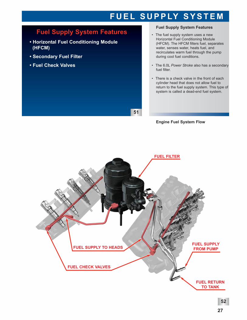
• The fuel supply system uses a newHorizontal Fuel Conditioning Module(HFCM). The HFCM filters fuel, separateswater, senses water, heats fuel, and recirculates warm fuel through the pumpduring cool fuel conditions.
• The 6.0L Power Stroke also has a secondaryfuel filter.
• There is a check valve in the front of eachcylinder head that does not allow fuel toreturn to the fuel supply system. This type ofsystem is called a dead-end fuel system.
Fuel Supply System Features
F U E L S U P P LY S Y S T E M
52
Engine Fuel System Flow
27
Fuel Supply System Features • Horizontal Fuel Conditioning Module
(HFCM)
• Secondary Fuel Filter
• Fuel Check Valves
51
FUEL SUPPLY TO HEADS
FUEL RETURNTO TANK
FUEL SUPPLYFROM PUMP
FUEL CHECK VALVES
FUEL FILTER
53
F U E L S U P P LY S Y S T E M
28
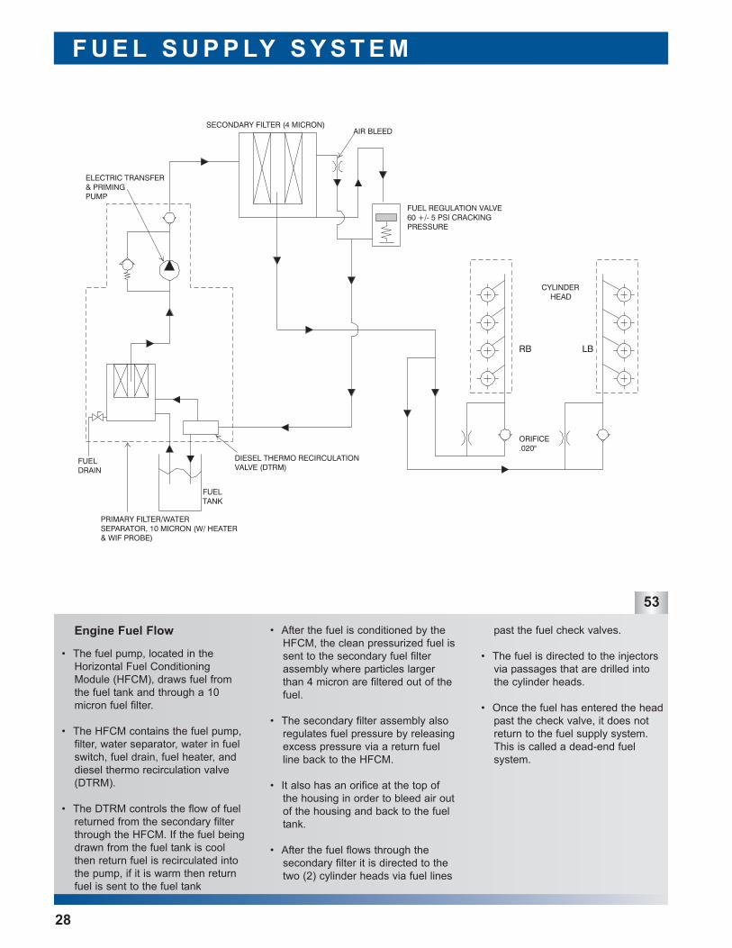
Engine Fuel Flow • After the fuel is conditioned by theHFCM, the clean pressurized fuel issent to the secondary fuel filterassembly where particles largerthan 4 micron are filtered out of thefuel.
• The secondary filter assembly alsoregulates fuel pressure by releasingexcess pressure via a return fuelline back to the HFCM.
• It also has an orifice at the top ofthe housing in order to bleed air outof the housing and back to the fueltank.
• After the fuel flows through the secondary filter it is directed to thetwo (2) cylinder heads via fuel lines
past the fuel check valves.
• The fuel is directed to the injectorsvia passages that are drilled intothe cylinder heads.
• Once the fuel has entered the headpast the check valve, it does notreturn to the fuel supply system.This is called a dead-end fuel system.
• The fuel pump, located in theHorizontal Fuel ConditioningModule (HFCM), draws fuel fromthe fuel tank and through a 10micron fuel filter.
• The HFCM contains the fuel pump,filter, water separator, water in fuelswitch, fuel drain, fuel heater, anddiesel thermo recirculation valve(DTRM).
• The DTRM controls the flow of fuelreturned from the secondary filterthrough the HFCM. If the fuel beingdrawn from the fuel tank is coolthen return fuel is recirculated intothe pump, if it is warm then returnfuel is sent to the fuel tank
54
55
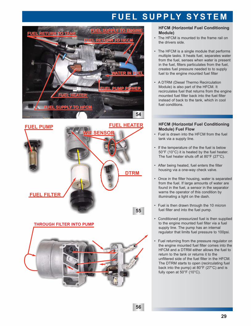
• Fuel is drawn into the HFCM from the fueltank via a supply line.
• If the temperature of the the fuel is below50°F (10°C) it is heated by the fuel heater.The fuel heater shuts off at 80°F (27°C).
• After being heated, fuel enters the filterhousing via a one-way check valve.
• Once in the filter housing, water is separatedfrom the fuel. If large amounts of water arefound in the fuel, a sensor in the separatorwarns the operator of this condition by illuminating a light on the dash.
• Fuel is then drawn through the 10 micronfuel filter and into the fuel pump.
• Conditioned pressurized fuel is then suppliedto the engine mounted fuel filter via a fuelsupply line. The pump has an internal regulator that limits fuel pressure to 100psi.
• Fuel returning from the pressure regulator onthe engine mounted fuel filter comes into theHFCM and a DTRM either allows the fuel toreturn to the tank or returns it to the unfiltered side of the fuel filter in the HFCM.The DTRM starts to open (recirculating fuelback into the pump) at 80°F (27°C) and isfully open at 50°F (10°C).
• The HFCM is mounted to the frame rail onthe drivers side.
• The HFCM is a single module that performsmultiple tasks. It heats fuel, separates waterfrom the fuel, senses when water is presentin the fuel, filters particulates from the fuel,creates fuel pressure needed to to supplyfuel to the engine mounted fuel filter
• A DTRM (Diesel Thermo RecirculationModule) is also part of the HFCM. It recirculates fuel that returns from the enginemounted fuel filter back into the fuel filterinstead of back to the tank, which in coolfuel conditions.
HFCM (Horizontal Fuel ConditioningModule) Fuel Flow
HFCM (Horizontal Fuel ConditioningModule)
F U E L S U P P LY S Y S T E M
29
56
WATER IN FUELWATER IN FUEL
FUEL PUMP POWERFUEL PUMP POWER
FUEL SUPPLY TO HFCMFUEL SUPPLY TO HFCM
FUEL RETURN TO TANKFUEL RETURN TO TANKFUEL RETURN TO HFCMFUEL RETURN TO HFCM
FUEL HEATERFUEL HEATER
FUEL SUPPLY TO ENGINEFUEL SUPPLY TO ENGINE
DTRM
WIF SENSORWIF SENSORFUEL HEATERFUEL PUMP
FUEL FILTER
THROUGH FILTER INTO PUMP
58
59
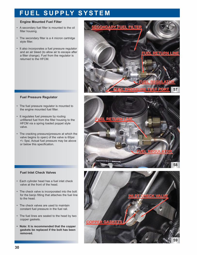
• A secondary fuel filter is mounted to the oilfilter housing.
• The secondary filter is a 4 micron cartridgestyle filter.
• It also incorporates a fuel pressure regulatorand an air bleed (to allow air to escape aftera filter change). Fuel from the regulator isreturned to the HFCM.
• The fuel pressure regulator is mounted tothe engine mounted fuel filter.
• It regulates fuel pressure by routing unfiltered fuel from the filter housing to theHFCM via a spring loaded poppet stylevalve.
• The cracking pressure(pressure at which thevalve begins to open) of the valve is 60psi+\- 5psi. Actual fuel pressure may be aboveor below this specification.
Fuel Inlet Check Valves
Fuel Pressure Regulator
F U E L S U P P LY S Y S T E M
30
• Each cylinder head has a fuel inlet checkvalve at the front of the head.
• The check valve is incorporated into the boltfor the banjo fitting that attaches the fuel lineto the head.
• The check valves are used to maintain constant fuel pressure in the fuel rail.
• The fuel lines are sealed to the head by twocopper gaskets.
• Note: It is recommended that the coppergaskets be replaced if the bolt has beenremoved.
Engine Mounted Fuel Filter
57
SECONDARY FUEL FILTERSECONDARY FUEL FILTER
FUEL PRESSURE TEST PORTFUEL PRESSURE TEST PORT
FUEL REGULATORFUEL REGULATOR
FUEL RETURN LINEFUEL RETURN LINE
FUEL REGULATORFUEL REGULATOR
FUEL RETURN LINEFUEL RETURN LINE
COPPER GASKETSCOPPER GASKETS
INLET CHECK VALVEINLET CHECK VALVE
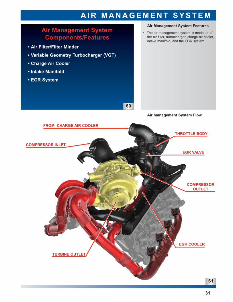
• The air management system is made up ofthe air filter, turbocharger, charge air cooler,intake manifold, and the EGR system.
Air Management System Features
A I R M A N A G E M E N T S Y S T E M
Air Management SystemComponents/Features
• Air Filter/Filter Minder
• Variable Geometry Turbocharger (VGT)
• Charge Air Cooler
• Intake Manifold
• EGR System
60
Air management System Flow
31
FROM CHARGE AIR COOLER
EGR VALVE
COMPRESSOROUTLET
EGR COOLER
TURBINE OUTLET
COMPRESSOR INLET
THROTTLE BODY
61
A I R M A N A G E M E N T S Y S T E M
62
32
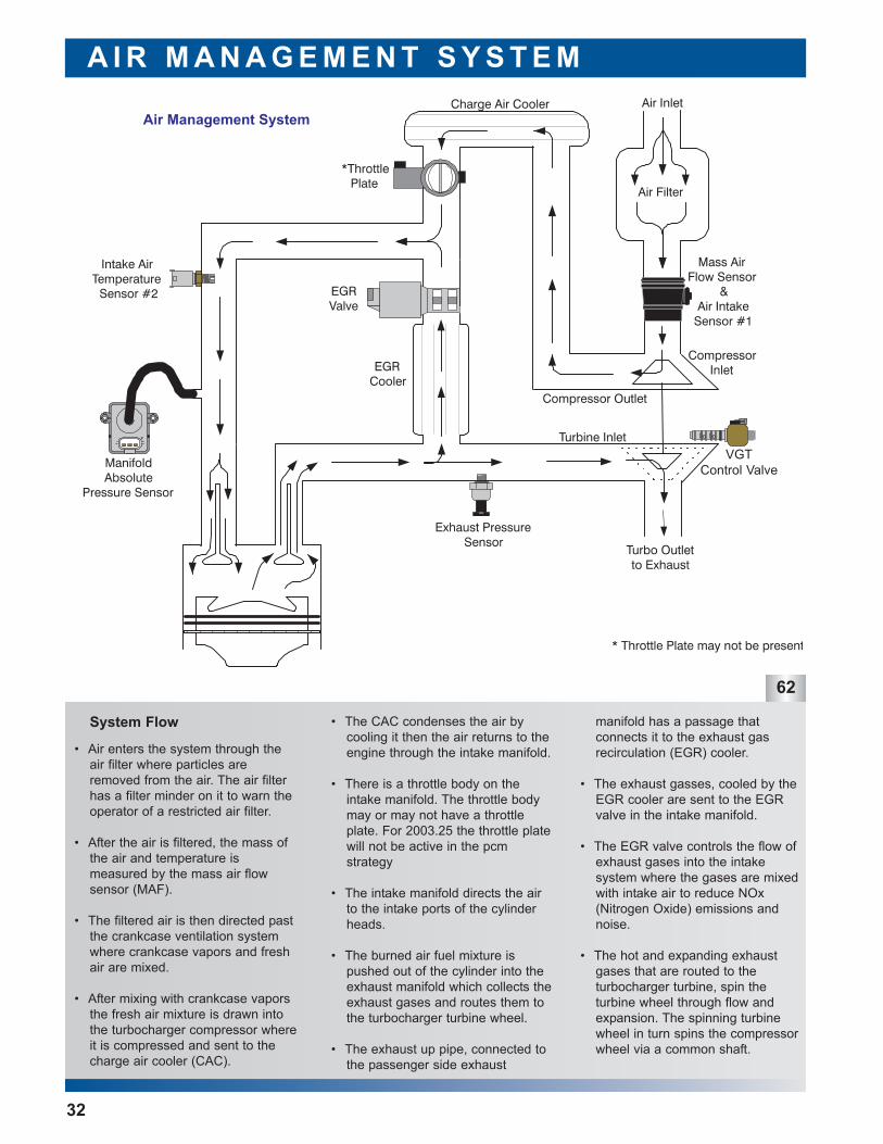
manifold has a passage that connects it to the exhaust gas recirculation (EGR) cooler.
• The exhaust gasses, cooled by theEGR cooler are sent to the EGRvalve in the intake manifold.
• The EGR valve controls the flow ofexhaust gases into the intake system where the gases are mixedwith intake air to reduce NOx(Nitrogen Oxide) emissions andnoise.
• The hot and expanding exhaustgases that are routed to the turbocharger turbine, spin the turbine wheel through flow andexpansion. The spinning turbinewheel in turn spins the compressorwheel via a common shaft.
• The CAC condenses the air bycooling it then the air returns to theengine through the intake manifold.
• There is a throttle body on theintake manifold. The throttle bodymay or may not have a throttleplate. For 2003.25 the throttle platewill not be active in the pcm strategy
• The intake manifold directs the airto the intake ports of the cylinderheads.
• The burned air fuel mixture ispushed out of the cylinder into theexhaust manifold which collects theexhaust gases and routes them tothe turbocharger turbine wheel.
• The exhaust up pipe, connected tothe passenger side exhaust
• Air enters the system through theair filter where particles areremoved from the air. The air filterhas a filter minder on it to warn theoperator of a restricted air filter.
• After the air is filtered, the mass ofthe air and temperature is measured by the mass air flow sensor (MAF).
• The filtered air is then directed pastthe crankcase ventilation systemwhere crankcase vapors and freshair are mixed.
• After mixing with crankcase vaporsthe fresh air mixture is drawn intothe turbocharger compressor whereit is compressed and sent to thecharge air cooler (CAC).
System Flow
VGTControl Valve
63
64
65
Air Filter Element
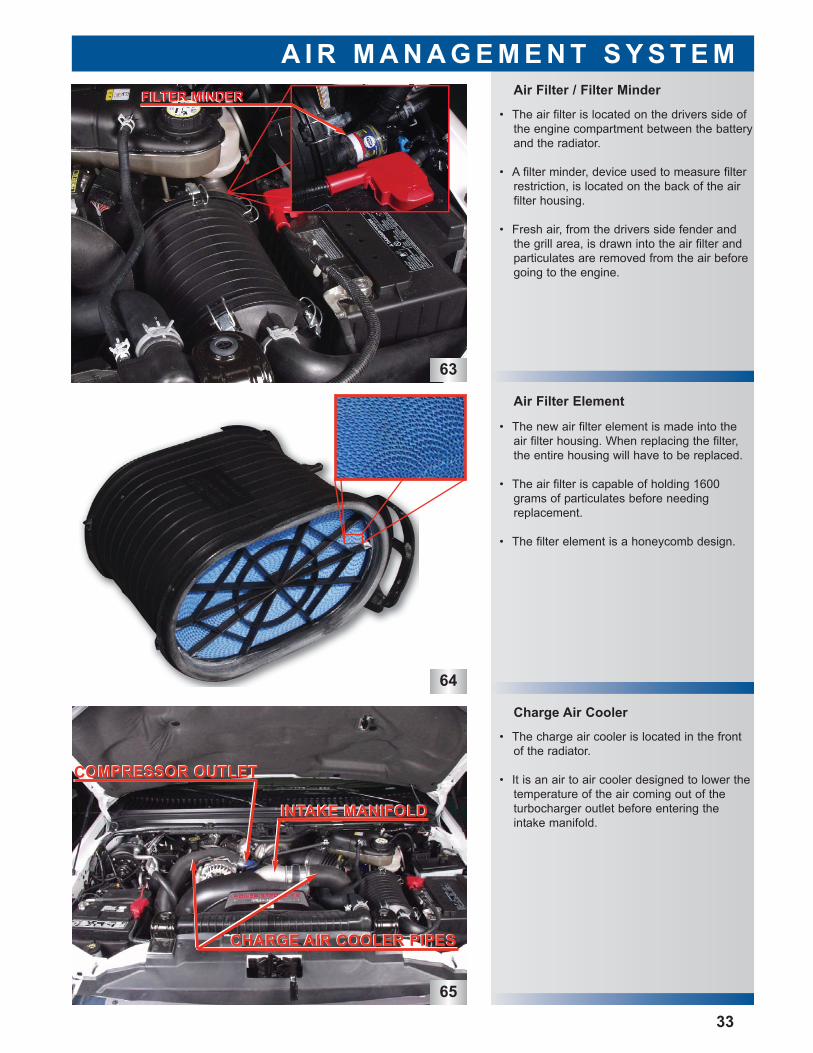
• The charge air cooler is located in the frontof the radiator.
• It is an air to air cooler designed to lower thetemperature of the air coming out of the turbocharger outlet before entering theintake manifold.
• The new air filter element is made into theair filter housing. When replacing the filter,the entire housing will have to be replaced.
• The air filter is capable of holding 1600grams of particulates before needingreplacement.
• The filter element is a honeycomb design.
• The air filter is located on the drivers side ofthe engine compartment between the batteryand the radiator.
• A filter minder, device used to measure filterrestriction, is located on the back of the airfilter housing.
• Fresh air, from the drivers side fender andthe grill area, is drawn into the air filter andparticulates are removed from the air beforegoing to the engine.
Charge Air Cooler
Air Filter / Filter Minder
A I R M A N A G E M E N T S Y S T E M
33
CHARGE AIR COOLER PIPESCHARGE AIR COOLER PIPES
COMPRESSOR OUTLETCOMPRESSOR OUTLET
INTAKE MANIFOLDINTAKE MANIFOLD
FILTER MINDERFILTER MINDER
67
68
VGT Turbine
VGT Compressor
VGT Features
A I R M A N A G E M E N T S Y S T E M
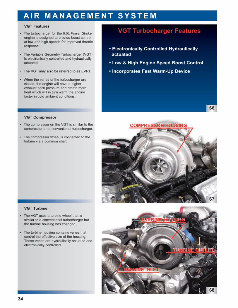
VGT Turbocharger Features
• Electronically Controlled Hydraulicallyactuated
• Low & High Engine Speed Boost Control
• Incorporates Fast Warm-Up Device
66
34
• The turbocharger for the 6.0L Power Strokeengine is designed to provide boost controlat low and high speeds for improved throttleresponse.
• The Variable Geometry Turbocharger (VGT)is electronically controlled and hydraulicallyactuated.
• The VGT may also be referred to as EVRT.
• When the vanes of the turbocharger areclosed, the engine will have a higherexhaust back pressure and create moreheat which will in turn warm the enginefaster in cold ambient conditions.
• The compressor on the VGT is similar to thecompressor on a conventional turbocharger.
• The compressor wheel is connected to theturbine via a common shaft.
• The VGT uses a turbine wheel that is similar to a conventional turbocharger butthe turbine housing has changed.
• The turbine housing contains vanes that control the effective size of the housing.These vanes are hydraulically actuated andelectronically controlled.
COMPRESSOR HOUSINGCOMPRESSOR HOUSING
TURBINE HOUSINGTURBINE HOUSING
TURBINE OUTLETTURBINE OUTLET
TURBINE INLETTURBINE INLET
69
VGT Control Valve
A I R M A N A G E M E N T S Y S T E M
35
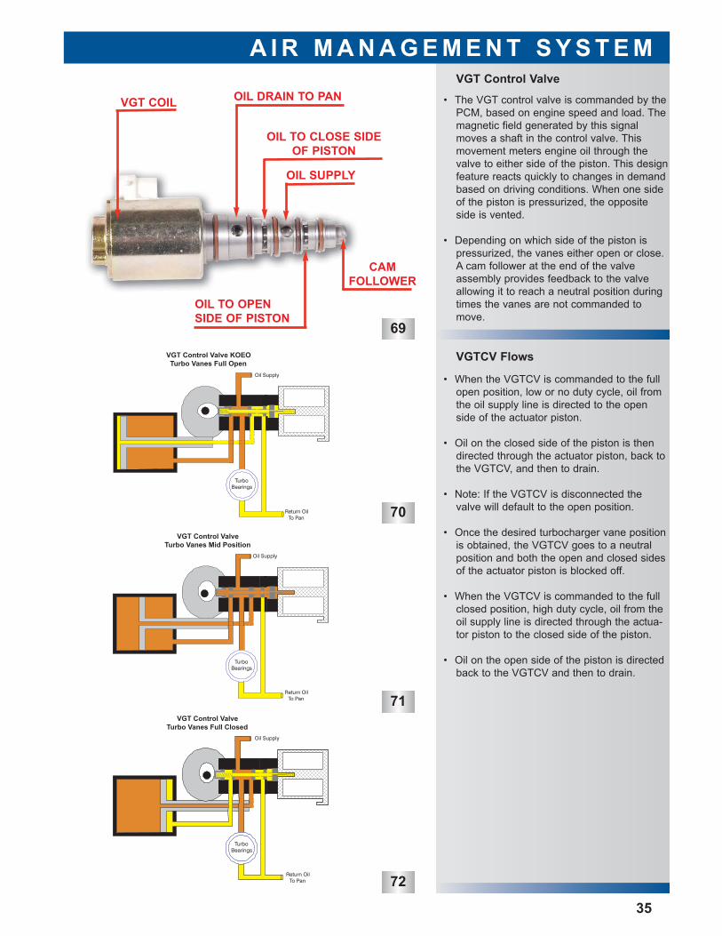
• The VGT control valve is commanded by thePCM, based on engine speed and load. Themagnetic field generated by this signalmoves a shaft in the control valve. Thismovement meters engine oil through thevalve to either side of the piston. This designfeature reacts quickly to changes in demandbased on driving conditions. When one sideof the piston is pressurized, the oppositeside is vented.
• Depending on which side of the piston ispressurized, the vanes either open or close.A cam follower at the end of the valveassembly provides feedback to the valveallowing it to reach a neutral position duringtimes the vanes are not commanded tomove.
VGT COIL OIL DRAIN TO PAN
OIL TO CLOSE SIDEOF PISTON
OIL SUPPLY
OIL TO OPENSIDE OF PISTON
CAMFOLLOWER
70
VGTCV Flows
• When the VGTCV is commanded to the fullopen position, low or no duty cycle, oil fromthe oil supply line is directed to the openside of the actuator piston.
• Oil on the closed side of the piston is thendirected through the actuator piston, back tothe VGTCV, and then to drain.
• Note: If the VGTCV is disconnected thevalve will default to the open position.
• Once the desired turbocharger vane positionis obtained, the VGTCV goes to a neutralposition and both the open and closed sidesof the actuator piston is blocked off.
• When the VGTCV is commanded to the fullclosed position, high duty cycle, oil from theoil supply line is directed through the actua-tor piston to the closed side of the piston.
• Oil on the open side of the piston is directedback to the VGTCV and then to drain.
72
71
75
VGT Turbine Vanes Open
A I R M A N A G E M E N T S Y S T E M
36
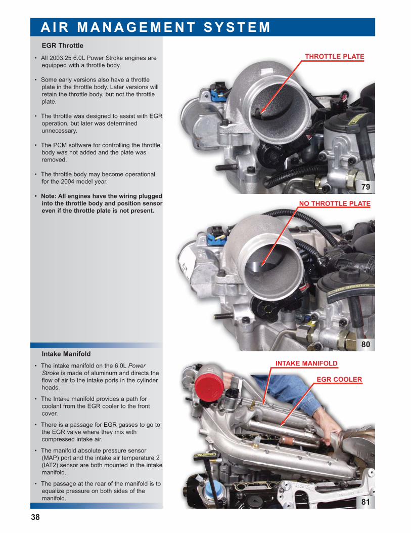
• During engine operation at high enginespeeds and load, there is a great deal ofenergy available in the exhaust.
• Excessive boost under high speed, high loadconditions can negatively affect componentdurability, therefore the vanes are commanded open preventing turbochargeroverspeed.
• Essentially, this allows the turbocharger toact as a large turbocharger.
ACTUATOR PISTON
UNISON RING
VANES
ACTUATOR PISTON
UNISON RING
VANES
74
UNISON RING
VANES
ACTUATOR PISTON
73
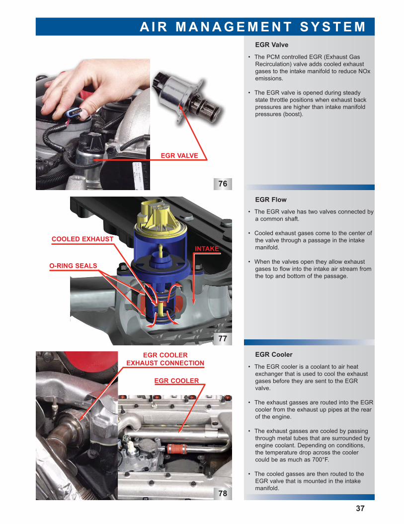
• During Engine operation at moderate enginespeeds and load, the vanes are commandedpartially open.
• The vanes are set to this intermediate posi-tion to supply the correct amount of boost tothe engine for optimal combustion as well asproviding the necessary back pressure todrive EGR.
• Note: The VGT control valve piston iscoupled to the vanes through a shaft andthe unison ring.
VGT Turbine Vanes Partially Closed
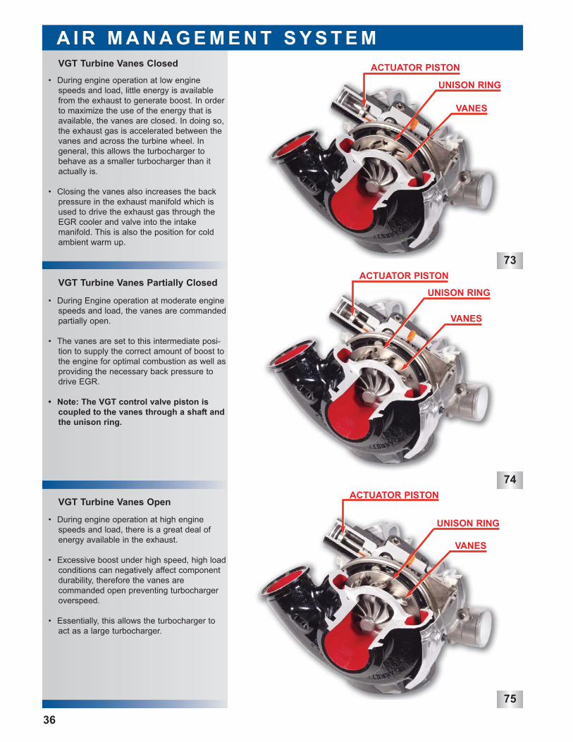
• During engine operation at low enginespeeds and load, little energy is availablefrom the exhaust to generate boost. In orderto maximize the use of the energy that isavailable, the vanes are closed. In doing so,the exhaust gas is accelerated between thevanes and across the turbine wheel. In general, this allows the turbocharger tobehave as a smaller turbocharger than itactually is.
• Closing the vanes also increases the backpressure in the exhaust manifold which isused to drive the exhaust gas through theEGR cooler and valve into the intake manifold. This is also the position for coldambient warm up.
VGT Turbine Vanes Closed
• The EGR cooler is a coolant to air heatexchanger that is used to cool the exhaustgases before they are sent to the EGRvalve.
• The exhaust gasses are routed into the EGRcooler from the exhaust up pipes at the rearof the engine.
• The exhaust gasses are cooled by passingthrough metal tubes that are surrounded byengine coolant. Depending on conditions,the temperature drop across the coolercould be as much as 700°F.
• The cooled gasses are then routed to theEGR valve that is mounted in the intakemanifold.
EGR Cooler
EGR Flow
EGR Valve
A I R M A N A G E M E N T S Y S T E M
37
• The PCM controlled EGR (Exhaust GasRecirculation) valve adds cooled exhaustgases to the intake manifold to reduce NOxemissions.
• The EGR valve is opened during steadystate throttle positions when exhaust backpressures are higher than intake manifoldpressures (boost).
• The EGR valve has two valves connected bya common shaft.
• Cooled exhaust gases come to the center ofthe valve through a passage in the intakemanifold.
• When the valves open they allow exhaustgases to flow into the intake air stream fromthe top and bottom of the passage.
76
78
77
EGR VALVE
EGR COOLER
EGR COOLEREXHAUST CONNECTION
COOLED EXHAUST
O-RING SEALS
INTAKE
A I R M A N A G E M E N T S Y S T E M
38
• The intake manifold on the 6.0L PowerStroke is made of aluminum and directs theflow of air to the intake ports in the cylinderheads.
• The Intake manifold provides a path forcoolant from the EGR cooler to the frontcover.
• There is a passage for EGR gasses to go tothe EGR valve where they mix with compressed intake air.
• The manifold absolute pressure sensor(MAP) port and the intake air temperature 2(IAT2) sensor are both mounted in the intakemanifold.
• The passage at the rear of the manifold is toequalize pressure on both sides of the manifold.
Intake ManifoldINTAKE MANIFOLD
EGR COOLER
81
NO THROTTLE PLATE
80
THROTTLE PLATE
79
• All 2003.25 6.0L Power Stroke engines areequipped with a throttle body.
• Some early versions also have a throttleplate in the throttle body. Later versions willretain the throttle body, but not the throttleplate.
• The throttle was designed to assist with EGRoperation, but later was determined unnecessary.
• The PCM software for controlling the throttlebody was not added and the plate wasremoved.
• The throttle body may become operationalfor the 2004 model year.
• Note: All engines have the wiring pluggedinto the throttle body and position sensoreven if the throttle plate is not present.
EGR Throttle
F U E L M A N A G E M E N T S Y S T E M
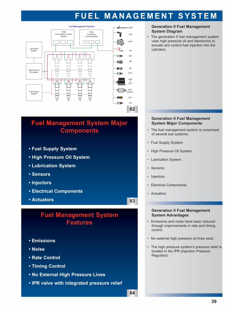
• The generation II fuel management systemuses high pressure oil and electronics toactuate and control fuel injection into thecylinders.
Generation II Fuel ManagementSystem Diagram
82
Fuel Management System MajorComponents
• Fuel Supply System
• High Pressure Oil System
• Lubrication System
• Sensors
• Injectors
• Electrical Components
• Actuators 83
• The fuel management system is comprisedof several sub systems.
• Fuel Supply System.
• High Pressure Oil System.
• Lubrication System.
• Sensors.
• Injectors.
• Electrical Components.
• Actuators.
Generation II Fuel ManagementSystem Major Components
Generation II Fuel ManagementSystem Advantages
• Emissions and noise have been reducedthrough improvements in rate and timingcontrol.
• No external high pressure oil lines exist.
• The high pressure system’s pressure relief islocated in the IPR (Injection PressureRegulator).
Fuel Management SystemFeatures
• Emissions
• Noise
• Rate Control
• Timing Control
• No External High Pressure Lines
• IPR valve with integrated pressure relief
84
39
High Pressure Oil System Flow
F U E L M A N A G E M E N T S Y S T E M
85
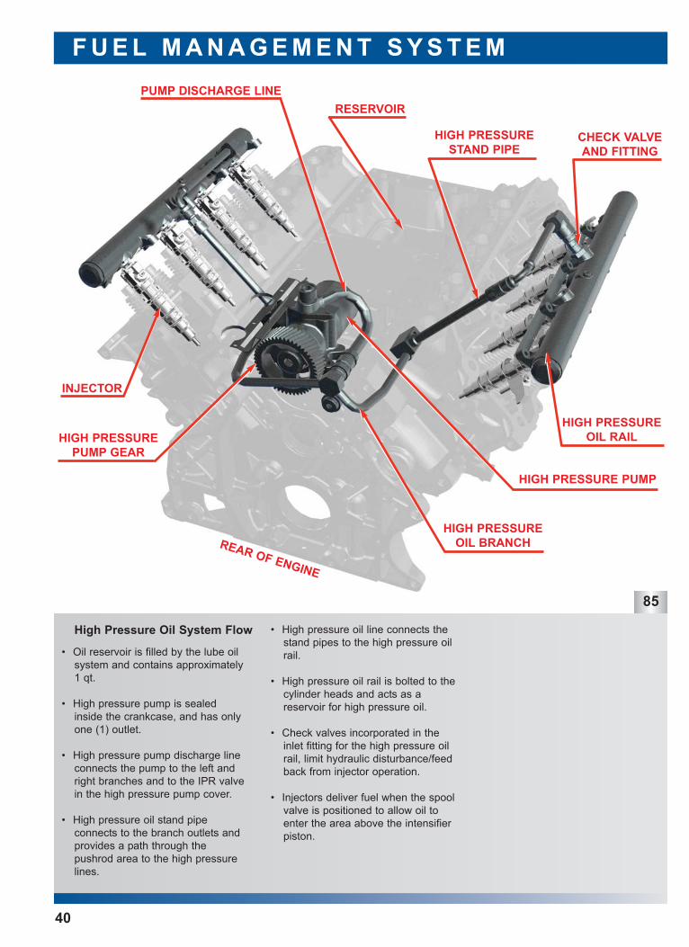
• Oil reservoir is filled by the lube oilsystem and contains approximately1 qt.
• High pressure pump is sealedinside the crankcase, and has onlyone (1) outlet.
• High pressure pump discharge lineconnects the pump to the left andright branches and to the IPR valvein the high pressure pump cover.
• High pressure oil stand pipe connects to the branch outlets andprovides a path through thepushrod area to the high pressurelines.
• High pressure oil line connects thestand pipes to the high pressure oilrail.
• High pressure oil rail is bolted to thecylinder heads and acts as a reservoir for high pressure oil.
• Check valves incorporated in theinlet fitting for the high pressure oilrail, limit hydraulic disturbance/feedback from injector operation.
• Injectors deliver fuel when the spoolvalve is positioned to allow oil toenter the area above the intensifierpiston.
40
HIGH PRESSUREOIL RAIL
RESERVOIR
INJECTOR
HIGH PRESSURE PUMP
PUMP DISCHARGE LINE
CHECK VALVEAND FITTING
HIGH PRESSURESTAND PIPE
HIGH PRESSUREOIL BRANCH
HIGH PRESSUREPUMP GEAR
REAR OF ENGINE
High Pressure Oil SystemSchematic
F U E L M A N A G E M E N T S Y S T E M
Oil Pump
Oil
Co
ole
r
Oil Filter Oil Reservoir forHigh PressurePump 0.95 Qt.
HighPressure
Pump
Hig
h P
ress
ure
Oil
Rai
l
Hig
h P
ress
ure
Oil
Rai
l
PumpBypass70 PSI
CoolerBypass25 PSI
FilterBypass20 PSI
IPR ValveDrain to Crankcase
High Pressure Oil System Schematic
Contains4000 PSI
Relief Valve
Check Valve with Orifice
ICPSensor
86
41
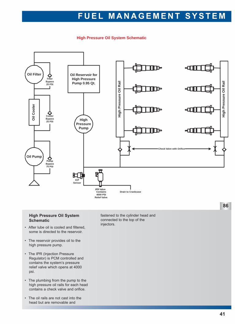
fastened to the cylinder head andconnected to the top of the injectors.
• After lube oil is cooled and filtered,some is directed to the reservoir.
• The reservoir provides oil to thehigh pressure pump.
• The IPR (Injection PressureRegulator) is PCM controlled andcontains the system’s pressurerelief valve which opens at 4000psi.
• The plumbing from the pump to thehigh pressure oil rails for each headcontains a check valve and orifice.
• The oil rails are not cast into thehead but are removable and
87
88
89
High Pressure Oil Rail with AWAFeature
IPR (Injection Control PressureRegulator) & ICP (Injection ControlPressure Sensor)
High Pressure Pump & Cover
F U E L M A N A G E M E N T S Y S T E M
42
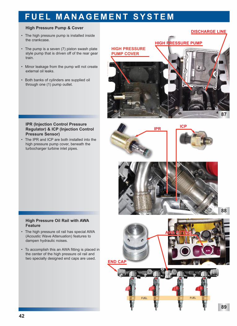
• The high pressure oil rail has special AWA(Acoustic Wave Attenuation) features todampen hydraulic noises.
• To accomplish this an AWA fitting is placed inthe center of the high pressure oil rail andtwo specially designed end caps are used.
• The IPR and ICP are both installed into thehigh pressure pump cover, beneath the turbocharger turbine inlet pipes.
• The high pressure pump is installed insidethe crankcase.
• The pump is a seven (7) piston swash platestyle pump that is driven off of the rear geartrain.
• Minor leakage from the pump will not createexternal oil leaks.
• Both banks of cylinders are supplied oilthrough one (1) pump outlet.
HIGH PRESSUREPUMP COVER
HIGH PRESSURE PUMP
DISCHARGE LINE
IPR ICP
AWA FITTINGAWA FITTING
END CAP
F U E L M A N A G E M E N T S Y S T E MFuel Injector Features
Injector & O-rings
Injector Coils & Spool Valve
91
92
43
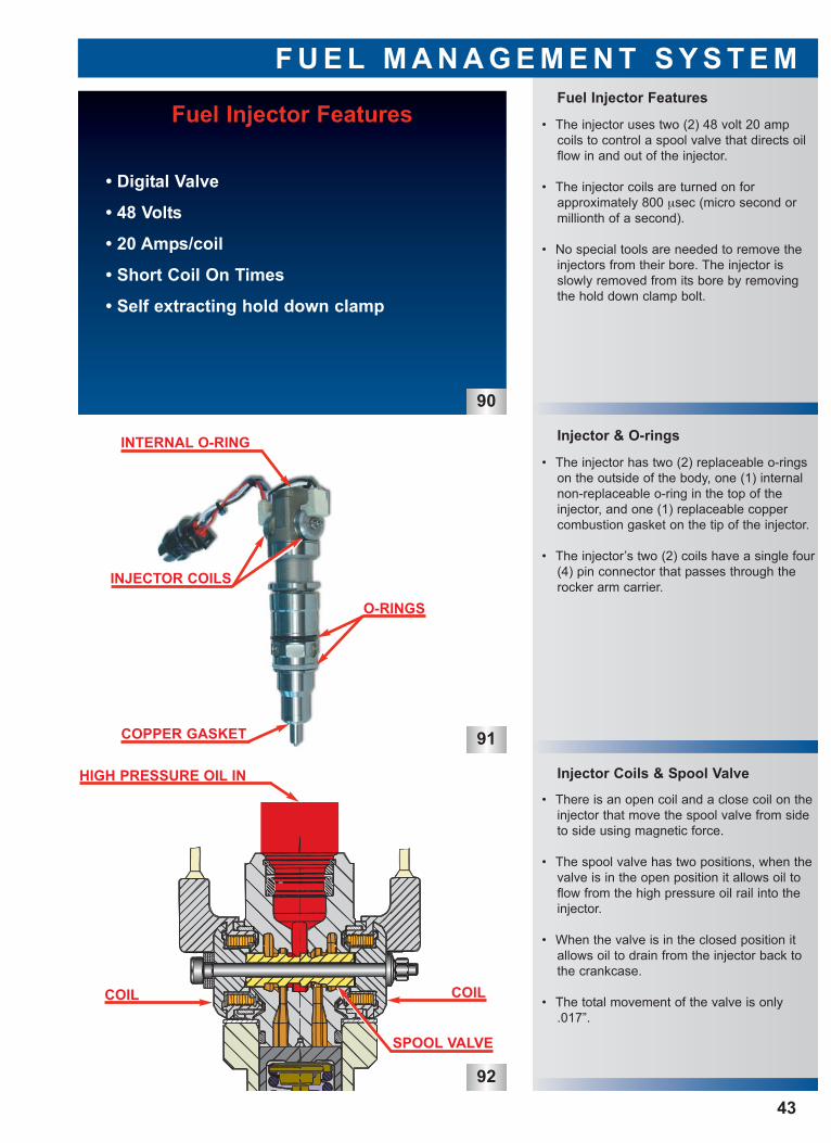
• The injector uses two (2) 48 volt 20 ampcoils to control a spool valve that directs oilflow in and out of the injector.
• The injector coils are turned on for approximately 800 µsec (micro second ormillionth of a second).
• No special tools are needed to remove theinjectors from their bore. The injector isslowly removed from its bore by removingthe hold down clamp bolt.
• The injector has two (2) replaceable o-ringson the outside of the body, one (1) internalnon-replaceable o-ring in the top of theinjector, and one (1) replaceable coppercombustion gasket on the tip of the injector.
• The injector’s two (2) coils have a single four(4) pin connector that passes through therocker arm carrier.
• There is an open coil and a close coil on theinjector that move the spool valve from sideto side using magnetic force.
• The spool valve has two positions, when thevalve is in the open position it allows oil toflow from the high pressure oil rail into theinjector.
• When the valve is in the closed position itallows oil to drain from the injector back tothe crankcase.
• The total movement of the valve is only.017”.
Fuel Injector Features
• Digital Valve
• 48 Volts
• 20 Amps/coil
• Short Coil On Times
• Self extracting hold down clamp
90
INJECTOR COILS
INTERNAL O-RING
O-RINGS
HIGH PRESSURE OIL IN
COPPER GASKET
COIL COIL
SPOOL VALVE
93
94
95
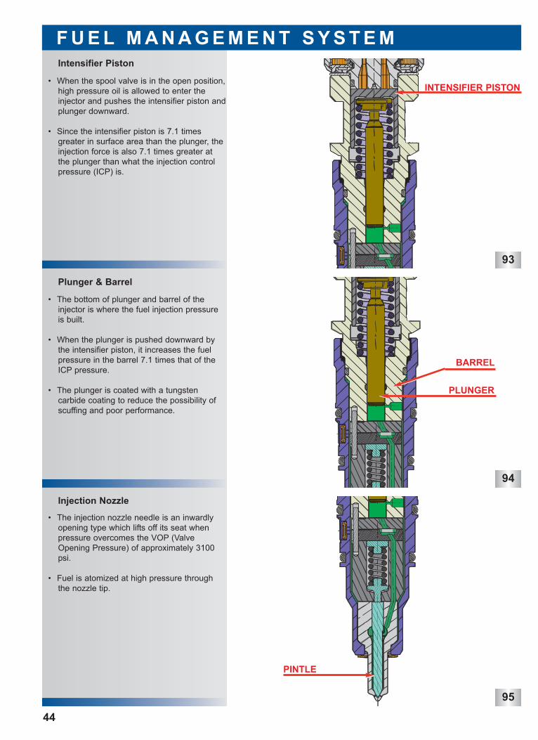
Injection Nozzle
Plunger & Barrel
Intensifier Piston
F U E L M A N A G E M E N T S Y S T E M
44
• When the spool valve is in the open position,high pressure oil is allowed to enter theinjector and pushes the intensifier piston andplunger downward.
• Since the intensifier piston is 7.1 timesgreater in surface area than the plunger, theinjection force is also 7.1 times greater atthe plunger than what the injection controlpressure (ICP) is.
• The bottom of plunger and barrel of theinjector is where the fuel injection pressureis built.
• When the plunger is pushed downward bythe intensifier piston, it increases the fuelpressure in the barrel 7.1 times that of theICP pressure.
• The plunger is coated with a tungsten carbide coating to reduce the possibility ofscuffing and poor performance.
• The injection nozzle needle is an inwardlyopening type which lifts off its seat whenpressure overcomes the VOP (ValveOpening Pressure) of approximately 3100psi.
• Fuel is atomized at high pressure throughthe nozzle tip.
INTENSIFIER PISTON
BARREL
PLUNGER
PINTLE

97
Fill Cycle
Stages of Injection
F U E L M A N A G E M E N T S Y S T E M
45
• The injection cycle has three (3) stages.
• Fill.
• Main injection.
• End of main injection.
• During some conditions the injector will perform all three steps of the injection cycletwo times per firing cycle. This is called pilotinjection.
• During the fill stage, the spool valve is in theclosed position.
• High pressure oil from the oil rail is deadheaded at the spool valve.
• Low pressure fuel fills the port below theplunger.
• The needle control spring holds the needleon its seat so that fuel can not enter thecombustion chamber.
Three Stages of Injection
• Fill
• Main Injection
• End of Main Injection
96
SPOOL VALVECLOSED
FUEL INLET
PINTLE CLOSED
INTENSIFIER PISTONAT REST
98
99
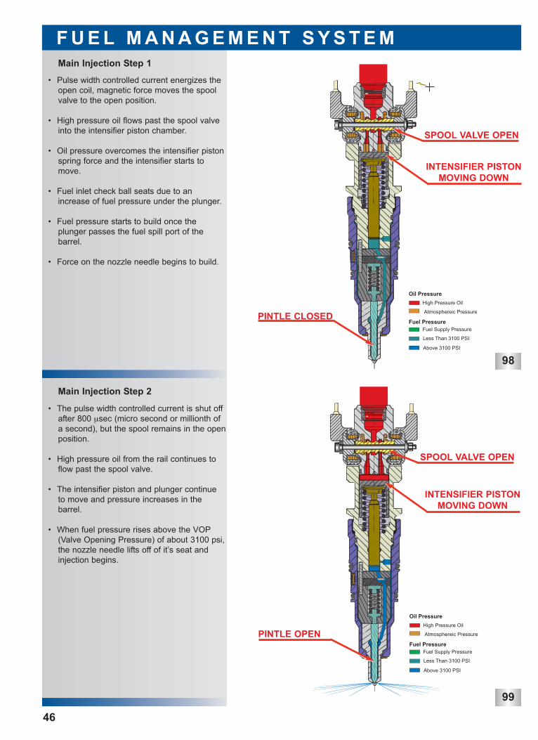
Main Injection Step 2
Main Injection Step 1
F U E L M A N A G E M E N T S Y S T E M
46
• Pulse width controlled current energizes theopen coil, magnetic force moves the spoolvalve to the open position.
• High pressure oil flows past the spool valveinto the intensifier piston chamber.
• Oil pressure overcomes the intensifier pistonspring force and the intensifier starts tomove.
• Fuel inlet check ball seats due to anincrease of fuel pressure under the plunger.
• Fuel pressure starts to build once theplunger passes the fuel spill port of the barrel.
• Force on the nozzle needle begins to build.
• The pulse width controlled current is shut offafter 800 µsec (micro second or millionth ofa second), but the spool remains in the openposition.
• High pressure oil from the rail continues toflow past the spool valve.
• The intensifier piston and plunger continueto move and pressure increases in the barrel.
• When fuel pressure rises above the VOP(Valve Opening Pressure) of about 3100 psi,the nozzle needle lifts off of it’s seat andinjection begins.
SPOOL VALVE OPEN
INTENSIFIER PISTONMOVING DOWN
PINTLE CLOSED
SPOOL VALVE OPEN
INTENSIFIER PISTONMOVING DOWN
PINTLE OPEN
100
101
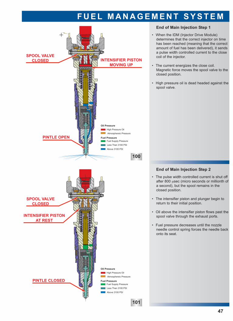
End of Main Injection Step 2
End of Main Injection Step 1
F U E L M A N A G E M E N T S Y S T E M
47
• When the IDM (Injector Drive Module) determines that the correct injector on timehas been reached (meaning that the correctamount of fuel has been delivered), it sendsa pulse width controlled current to the closecoil of the injector.
• The current energizes the close coil.Magnetic force moves the spool valve to theclosed position.
• High pressure oil is dead headed against thespool valve.
• The pulse width controlled current is shut offafter 800 µsec (micro seconds or millionth ofa second), but the spool remains in theclosed position.
• The intensifier piston and plunger begin toreturn to their initial position.
• Oil above the intensifier piston flows past thespool valve through the exhaust ports.
• Fuel pressure decreases until the nozzleneedle control spring forces the needle backonto its seat.
SPOOL VALVECLOSED
SPOOL VALVECLOSED
INTENSIFIER PISTONMOVING UP
PINTLE OPEN
INTENSIFIER PISTONAT REST
PINTLE CLOSED

48
This page intent ional lyleft blank
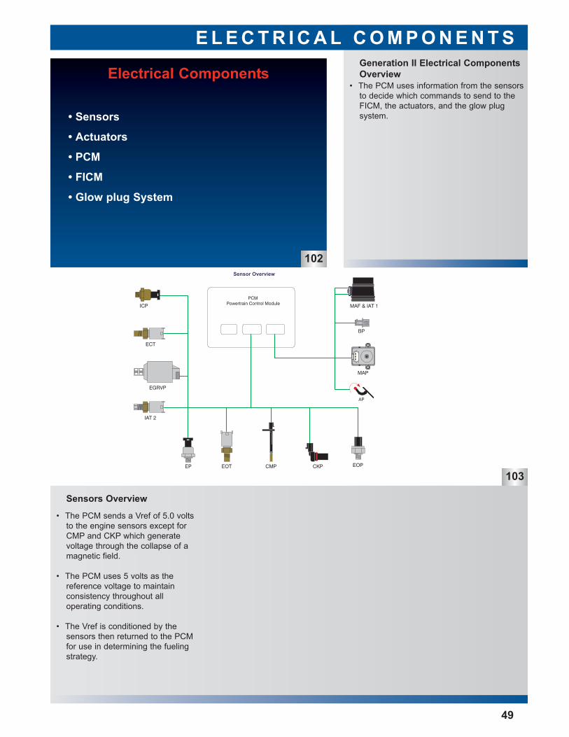
• The PCM uses information from the sensorsto decide which commands to send to theFICM, the actuators, and the glow plug system.
Generation II Electrical ComponentsOverview
E L E C T R I C A L C O M P O N E N T S
103
49
• The PCM sends a Vref of 5.0 voltsto the engine sensors except forCMP and CKP which generate voltage through the collapse of amagnetic field.
• The PCM uses 5 volts as the reference voltage to maintain consistency throughout all operating conditions.
• The Vref is conditioned by the sensors then returned to the PCMfor use in determining the fueling strategy.
Sensors Overview
Electrical Components
• Sensors
• Actuators
• PCM
• FICM
• Glow plug System
102
AP (Accelerator PedalPosition)
E L E C T R I C A L C O M P O N E N T S
104
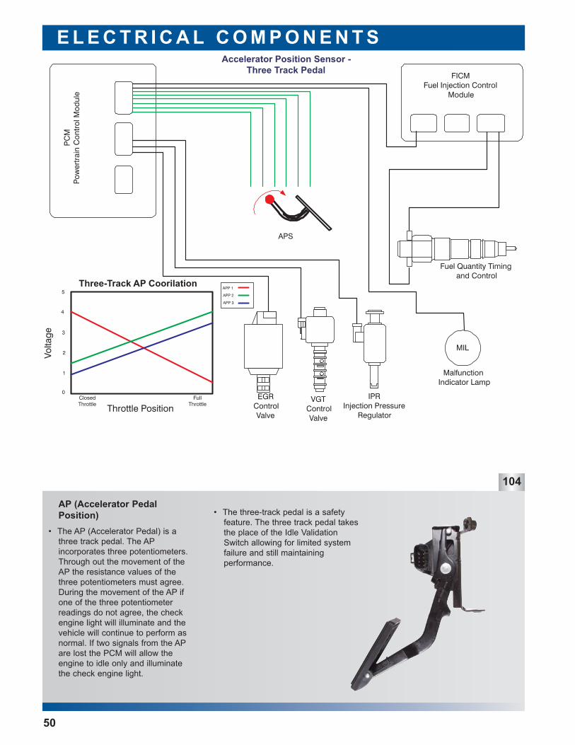
• The AP (Accelerator Pedal) is athree track pedal. The APincorporates three potentiometers.Through out the movement of theAP the resistance values of thethree potentiometers must agree.During the movement of the AP ifone of the three potentiometerreadings do not agree, the checkengine light will illuminate and thevehicle will continue to perform asnormal. If two signals from the APare lost the PCM will allow theengine to idle only and illuminatethe check engine light.
• The three-track pedal is a safetyfeature. The three track pedal takesthe place of the Idle ValidationSwitch allowing for limited systemfailure and still maintaining performance.
50
Baro (Barometric Pressure)
E L E C T R I C A L C O M P O N E N T S
105
51
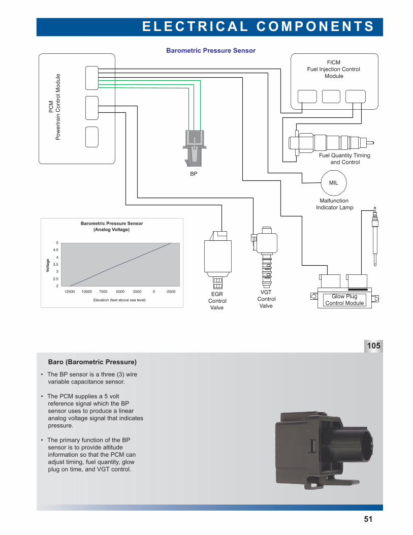
• The BP sensor is a three (3) wirevariable capacitance sensor.
• The PCM supplies a 5 volt reference signal which the BPsensor uses to produce a linearanalog voltage signal that indicatespressure.
• The primary function of the BPsensor is to provide altitude information so that the PCM canadjust timing, fuel quantity, glowplug on time, and VGT control.
CKP (Crankshaft Position)
E L E C T R I C A L C O M P O N E N T S
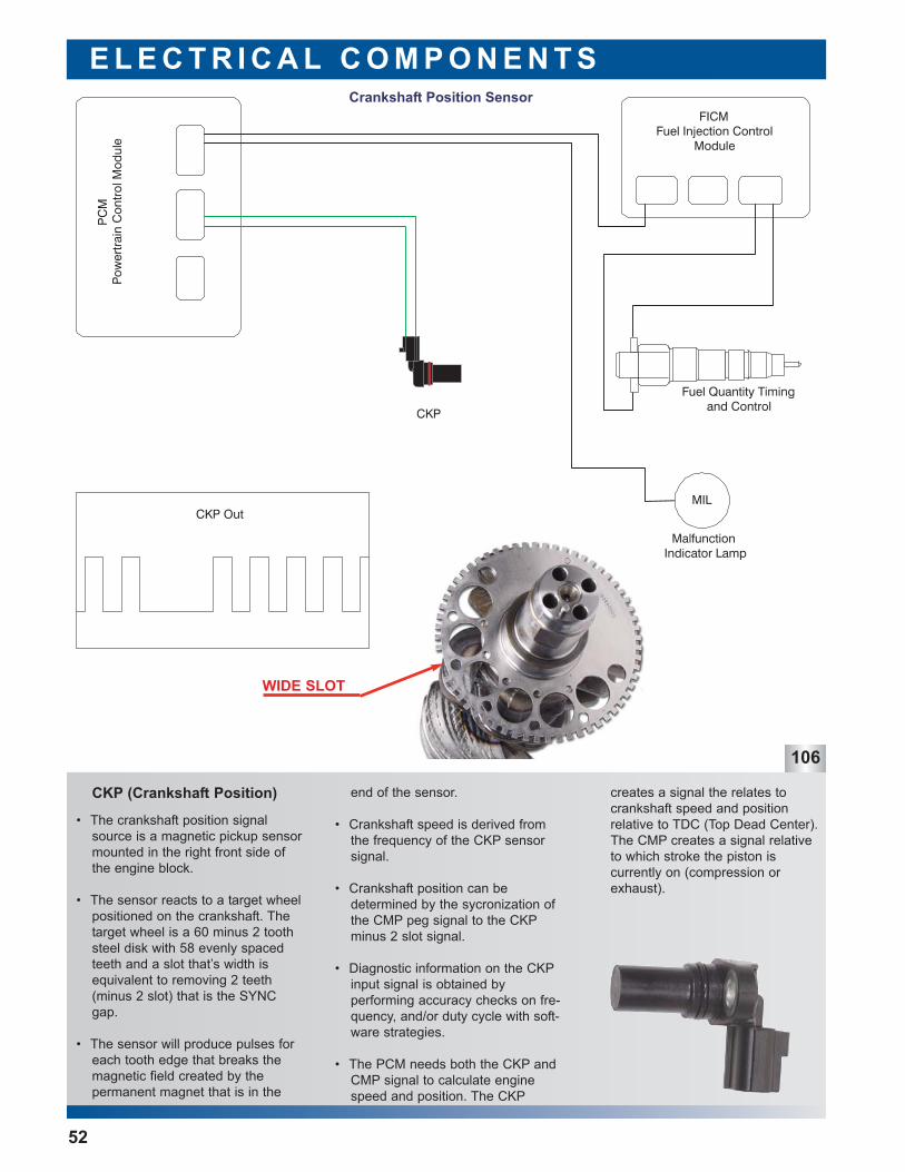
• The crankshaft position signalsource is a magnetic pickup sensormounted in the right front side ofthe engine block.
• The sensor reacts to a target wheelpositioned on the crankshaft. Thetarget wheel is a 60 minus 2 toothsteel disk with 58 evenly spacedteeth and a slot that’s width isequivalent to removing 2 teeth(minus 2 slot) that is the SYNCgap.
• The sensor will produce pulses foreach tooth edge that breaks themagnetic field created by the permanent magnet that is in the
106
creates a signal the relates tocrankshaft speed and position relative to TDC (Top Dead Center).The CMP creates a signal relativeto which stroke the piston is currently on (compression orexhaust).
end of the sensor.
• Crankshaft speed is derived fromthe frequency of the CKP sensorsignal.
• Crankshaft position can be determined by the sycronization ofthe CMP peg signal to the CKPminus 2 slot signal.
• Diagnostic information on the CKPinput signal is obtained by performing accuracy checks on fre-quency, and/or duty cycle with soft-ware strategies.
• The PCM needs both the CKP andCMP signal to calculate enginespeed and position. The CKP
52
WIDE SLOT
CMP (Camshaft Position)
E L E C T R I C A L C O M P O N E N T S
107
53
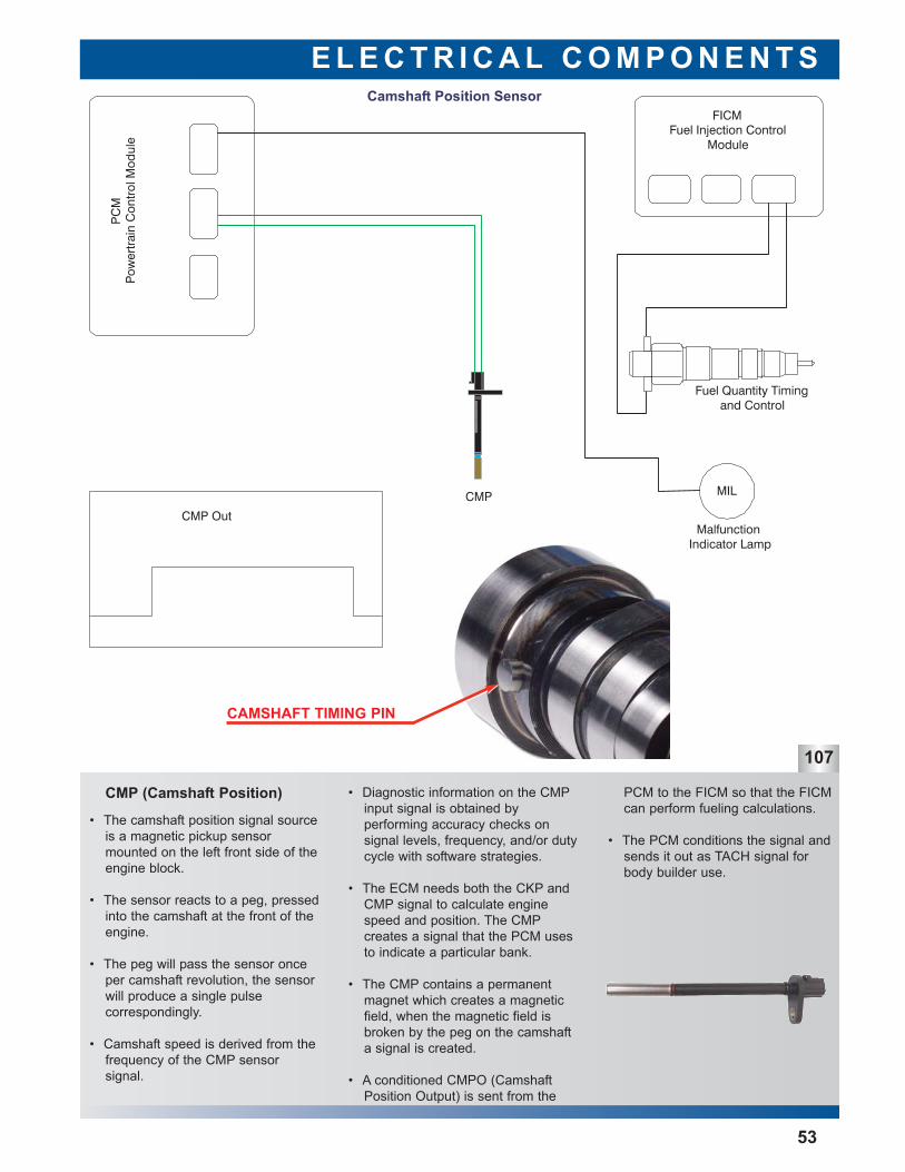
• The camshaft position signal sourceis a magnetic pickup sensor mounted on the left front side of theengine block.
• The sensor reacts to a peg, pressedinto the camshaft at the front of theengine.
• The peg will pass the sensor onceper camshaft revolution, the sensorwill produce a single pulse correspondingly.
• Camshaft speed is derived from thefrequency of the CMP sensor signal.
PCM to the FICM so that the FICMcan perform fueling calculations.
• The PCM conditions the signal andsends it out as TACH signal forbody builder use.
• Diagnostic information on the CMPinput signal is obtained by performing accuracy checks on signal levels, frequency, and/or dutycycle with software strategies.
• The ECM needs both the CKP andCMP signal to calculate enginespeed and position. The CMPcreates a signal that the PCM usesto indicate a particular bank.
• The CMP contains a permanentmagnet which creates a magneticfield, when the magnetic field isbroken by the peg on the camshafta signal is created.
• A conditioned CMPO (CamshaftPosition Output) is sent from the
CAMSHAFT TIMING PIN
E L E C T R I C A L C O M P O N E N T S
108
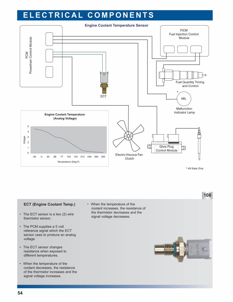
ECT (Engine Coolant Temp.) • When the temperature of thecoolant increases, the resistance ofthe thermistor decreases and thesignal voltage decreases.
• The ECT sensor is a two (2) wirethermistor sensor.
• The PCM supplies a 5 volt reference signal which the ECTsensor uses to produce an analogvoltage.
• The ECT sensor changes resistance when exposed to different temperatures.
• When the temperature of thecoolant decreases, the resistanceof the thermistor increases and thesignal voltage increases.
54
E L E C T R I C A L C O M P O N E N T S
109
55
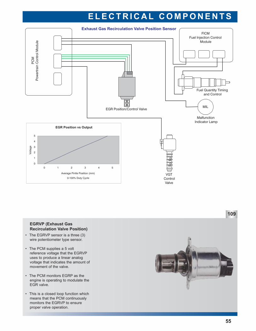
EGRVP (Exhaust GasRecirculation Valve Position)
• The EGRVP sensor is a three (3)wire potentiometer type sensor.
• The PCM supplies a 5 volt reference voltage that the EGRVPuses to produce a linear analogvoltage that indicates the amount ofmovement of the valve.
• The PCM monitors EGRP as theengine is operating to modulate theEGR valve.
• This is a closed loop function whichmeans that the PCM continuouslymonitors the EGRVP to ensure proper valve operation.
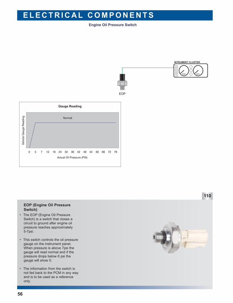
EOP (Engine Oil PressureSwitch)
E L E C T R I C A L C O M P O N E N T S
110
• The EOP (Engine Oil PressureSwitch) is a switch that closes a circuit to ground after engine oilpressure reaches approximately 5-7psi.
• This switch controls the oil pressuregauge on the instrument panel.When pressure is above 7psi thegauge will read normal and if thepressure drops below 6 psi thegauge will show 0.
• The information from the switch isnot fed back to the PCM in any wayand is to be used as a referenceonly.
56
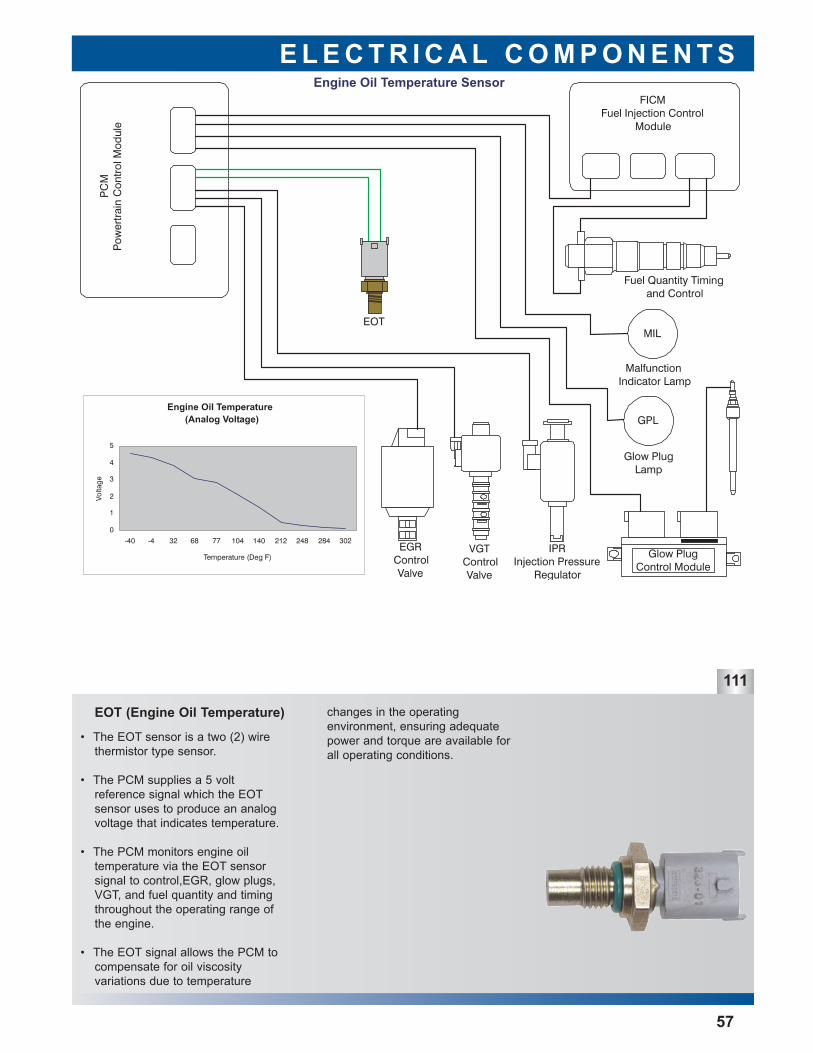
EOT (Engine Oil Temperature)
E L E C T R I C A L C O M P O N E N T S
111
57
• The EOT sensor is a two (2) wirethermistor type sensor.
• The PCM supplies a 5 volt reference signal which the EOTsensor uses to produce an analogvoltage that indicates temperature.
• The PCM monitors engine oil temperature via the EOT sensorsignal to control,EGR, glow plugs,VGT, and fuel quantity and timingthroughout the operating range ofthe engine.
• The EOT signal allows the PCM tocompensate for oil viscosity variations due to temperature
changes in the operating environment, ensuring adequatepower and torque are available forall operating conditions.
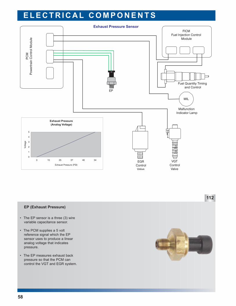
EP (Exhaust Pressure)
E L E C T R I C A L C O M P O N E N T S
112
• The EP sensor is a three (3) wirevariable capacitance sensor.
• The PCM supplies a 5 volt reference signal which the EPsensor uses to produce a linearanalog voltage that indicates pressure.
• The EP measures exhaust backpressure so that the PCM can control the VGT and EGR system.
58
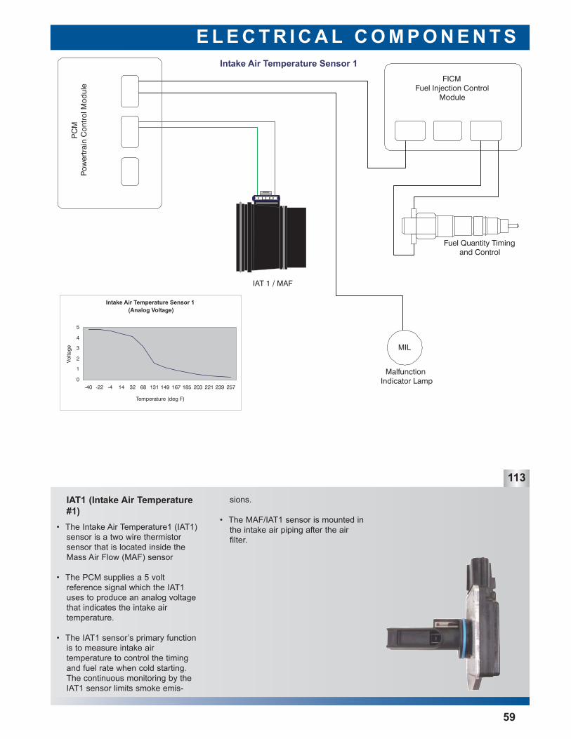
IAT1 (Intake Air Temperature#1)
E L E C T R I C A L C O M P O N E N T S
113
59
• The Intake Air Temperature1 (IAT1)sensor is a two wire thermistor sensor that is located inside theMass Air Flow (MAF) sensor
• The PCM supplies a 5 volt reference signal which the IAT1uses to produce an analog voltagethat indicates the intake air temperature.
• The IAT1 sensor’s primary functionis to measure intake air temperature to control the timingand fuel rate when cold starting.The continuous monitoring by theIAT1 sensor limits smoke emis-
sions.
• The MAF/IAT1 sensor is mounted inthe intake air piping after the air filter.
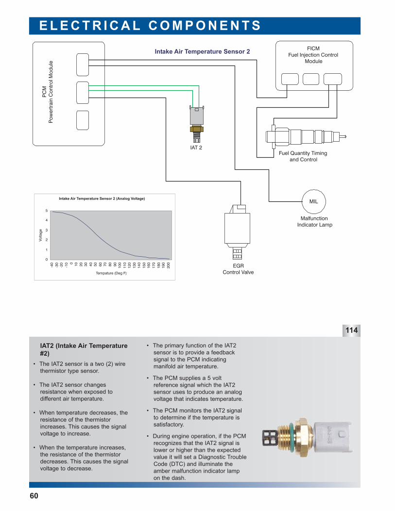
IAT2 (Intake Air Temperature#2)
E L E C T R I C A L C O M P O N E N T S
114
• The primary function of the IAT2sensor is to provide a feedback signal to the PCM indicating manifold air temperature.
• The PCM supplies a 5 volt reference signal which the IAT2sensor uses to produce an analogvoltage that indicates temperature.
• The PCM monitors the IAT2 signalto determine if the temperature issatisfactory.
• During engine operation, if the PCMrecognizes that the IAT2 signal islower or higher than the expectedvalue it will set a Diagnostic TroubleCode (DTC) and illuminate theamber malfunction indicator lampon the dash.
• The IAT2 sensor is a two (2) wirethermistor type sensor.
• The IAT2 sensor changes resistance when exposed to different air temperature.
• When temperature decreases, theresistance of the thermistor increases. This causes the signalvoltage to increase.
• When the temperature increases,the resistance of the thermistordecreases. This causes the signalvoltage to decrease.
60
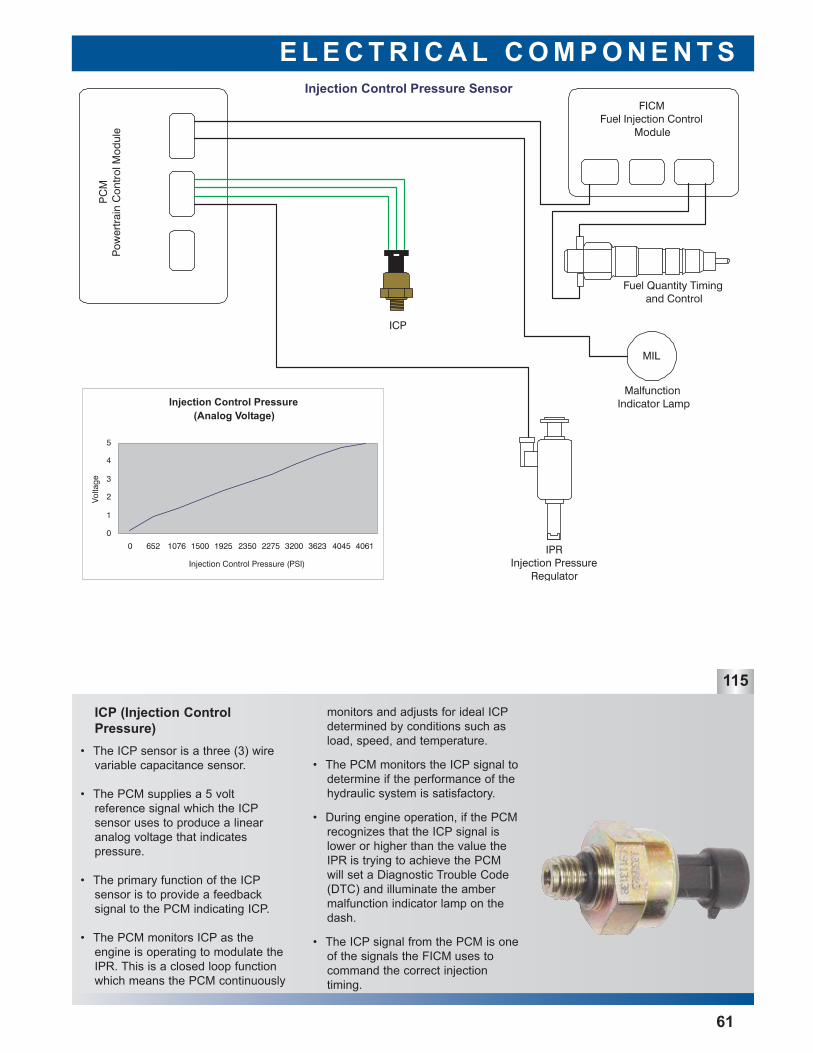
ICP (Injection ControlPressure)
E L E C T R I C A L C O M P O N E N T S
115
61
monitors and adjusts for ideal ICPdetermined by conditions such asload, speed, and temperature.
• The PCM monitors the ICP signal todetermine if the performance of thehydraulic system is satisfactory.
• During engine operation, if the PCMrecognizes that the ICP signal islower or higher than the value theIPR is trying to achieve the PCMwill set a Diagnostic Trouble Code(DTC) and illuminate the ambermalfunction indicator lamp on thedash.
• The ICP signal from the PCM is oneof the signals the FICM uses tocommand the correct injection timing.
• The ICP sensor is a three (3) wirevariable capacitance sensor.
• The PCM supplies a 5 volt reference signal which the ICPsensor uses to produce a linearanalog voltage that indicates pressure.
• The primary function of the ICPsensor is to provide a feedback signal to the PCM indicating ICP.
• The PCM monitors ICP as theengine is operating to modulate theIPR. This is a closed loop functionwhich means the PCM continuously
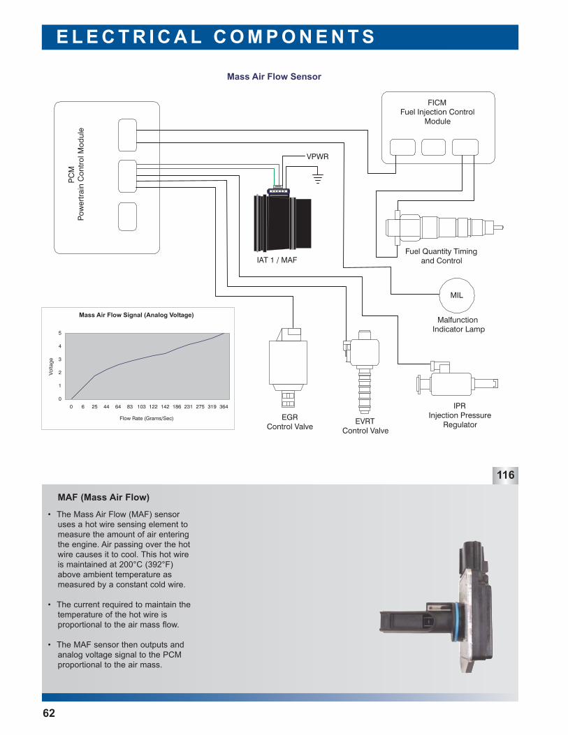
MAF (Mass Air Flow)
E L E C T R I C A L C O M P O N E N T S
62
• The Mass Air Flow (MAF) sensoruses a hot wire sensing element tomeasure the amount of air enteringthe engine. Air passing over the hotwire causes it to cool. This hot wireis maintained at 200°C (392°F)above ambient temperature asmeasured by a constant cold wire.
• The current required to maintain thetemperature of the hot wire is proportional to the air mass flow.
• The MAF sensor then outputs andanalog voltage signal to the PCMproportional to the air mass.
116
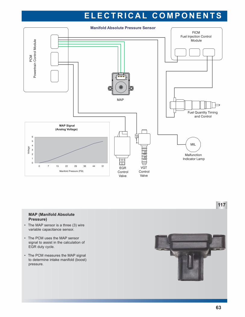
MAP (Manifold AbsolutePressure)
E L E C T R I C A L C O M P O N E N T S
63
117
• The MAP sensor is a three (3) wirevariable capacitance sensor.
• The PCM uses the MAP sensor signal to assist in the calculation ofEGR duty cycle.
• The PCM measures the MAP signalto determine intake manifold (boost)pressure.
119
120
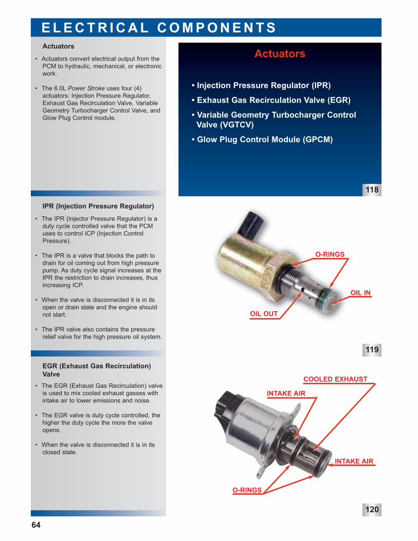
• The EGR (Exhaust Gas Recirculation) valveis used to mix cooled exhaust gasses withintake air to lower emissions and noise.
• The EGR valve is duty cycle controlled, thehigher the duty cycle the more the valveopens.
• When the valve is disconnected it is in itsclosed state.
• The IPR (Injector Pressure Regulator) is aduty cycle controlled valve that the PCMuses to control ICP (Injection ControlPressure).
• The IPR is a valve that blocks the path todrain for oil coming out from high pressurepump. As duty cycle signal increases at theIPR the restriction to drain increases, thusincreasing ICP.
• When the valve is disconnected it is in itsopen or drain state and the engine shouldnot start.
• The IPR valve also contains the pressurerelief valve for the high pressure oil system.
• Actuators convert electrical output from thePCM to hydraulic, mechanical, or electronicwork.
• The 6.0L Power Stroke uses four (4) actuators: Injection Pressure Regulator,Exhaust Gas Recirculation Valve, VariableGeometry Turbocharger Control Valve, andGlow Plug Control module.
EGR (Exhaust Gas Recirculation)Valve
IPR (Injection Pressure Regulator)
Actuators
E L E C T R I C A L C O M P O N E N T S
64
Actuators
• Injection Pressure Regulator (IPR)
• Exhaust Gas Recirculation Valve (EGR)
• Variable Geometry Turbocharger ControlValve (VGTCV)
• Glow Plug Control Module (GPCM)
118
OIL IN
O-RINGS
OIL OUT
O-RINGS
COOLED EXHAUST
INTAKE AIR
INTAKE AIR
121
123
FICM (Fuel Injection Control Module)
• Other electrical system components includethe FICM, PCM, and the glow plug system.
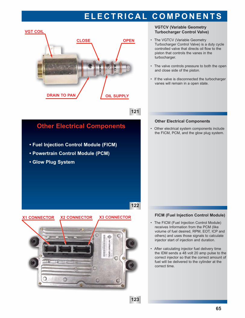
• The VGTCV (Variable GeometryTurbocharger Control Valve) is a duty cyclecontrolled valve that directs oil flow to thepiston that controls the vanes in the turbocharger.
• The valve controls pressure to both the openand close side of the piston.
• If the valve is disconnected the turbochargervanes will remain in a open state.
Other Electrical Components
VGTCV (Variable GeometryTurbocharger Control Valve)
E L E C T R I C A L C O M P O N E N T S
65
• The FICM (Fuel Injection Control Module)receives Information from the PCM (like volume of fuel desired, RPM, EOT, ICP andothers) and uses those signals to calculateinjector start of injection and duration.
• After calculating injector fuel delivery timethe IDM sends a 48 volt 20 amp pulse to thecorrect injector so that the correct amount offuel will be delivered to the cylinder at thecorrect time.
Other Electrical Components
• Fuel Injection Control Module (FICM)
• Powertrain Control Module (PCM)
• Glow Plug System
122
CLOSE OPEN
OIL SUPPLYDRAIN TO PAN
VGT COIL
X3 CONNECTORX2 CONNECTORX1 CONNECTOR
124
125
126
• The GPCM (Glow Plug Control Module) is aunit that controls the glow plugs in order towarm the air in the cylinders.
• The GPCM uses a glow plug enable signalto turn the glow plugs on for a time controlled by the PCM.
• The GPCM is capable of diagnosing a problem with one glow plug and then sending a diagnostic signal to the PCM.
• It also has the ability to turn off one glowplug if a short is detected in that circuit.
• The glow plug system is used to warm theair in the cylinders to enhance cold weatherstartability and reduce start up smoke.
• The glow plug system is PCM controlled.
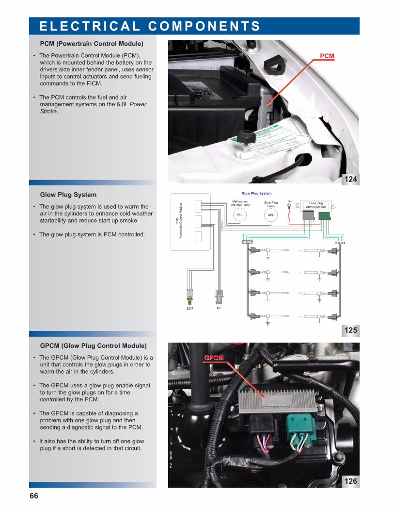
• The Powertrain Control Module (PCM),which is mounted behind the battery on thedrivers side inner fender panel, uses sensorinputs to control actuators and send fuelingcommands to the FICM.
• The PCM controls the fuel and air management systems on the 6.0L PowerStroke.
GPCM (Glow Plug Control Module)
Glow Plug System
E L E C T R I C A L C O M P O N E N T S
66
PCM (Powertrain Control Module)
PCM
GPCMGPCM
127
128
129
• Each bank of glow plugs is connected to thewiring harness via a glow plug buss bar.
• The glow plug buss bar has four connectorsattached to a single metal rail.
• The entire rail must be removed to gainaccess to any of the glow plugs on thatbank.
Glow Plug Buss Bar
Glow Plug Sleeve
Glow Plug
E L E C T R I C A L C O M P O N E N T S
67
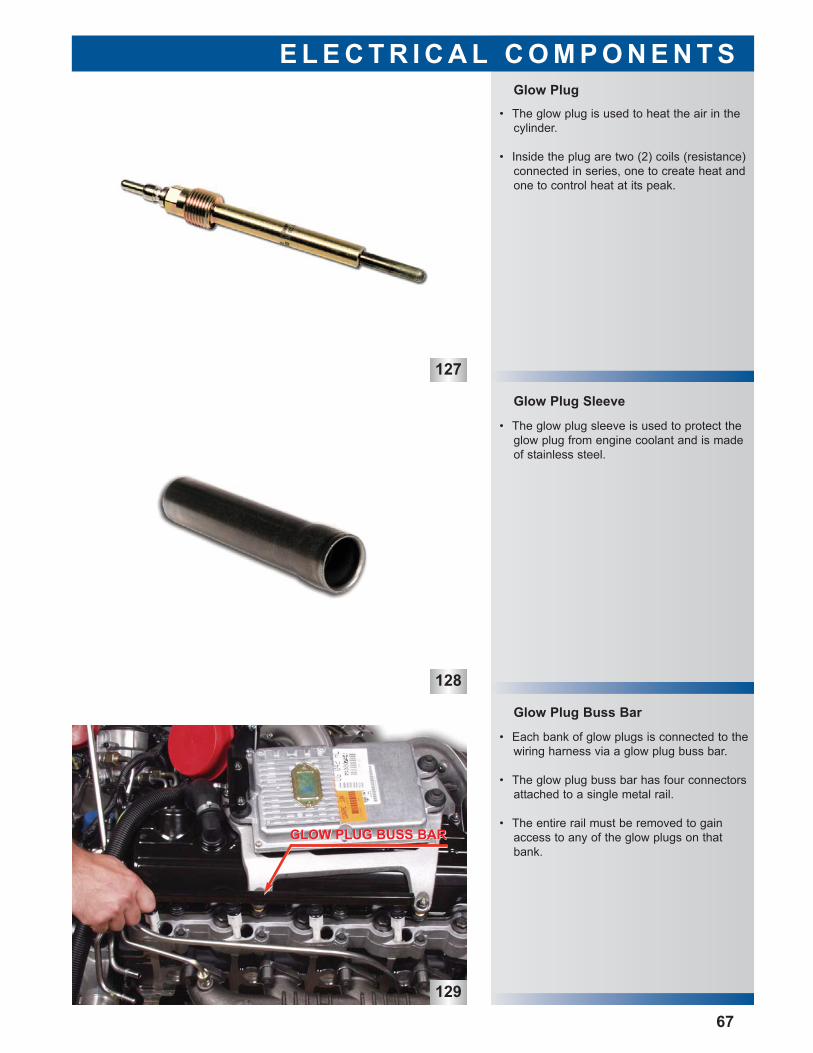
• The glow plug is used to heat the air in thecylinder.
• Inside the plug are two (2) coils (resistance)connected in series, one to create heat andone to control heat at its peak.
• The glow plug sleeve is used to protect theglow plug from engine coolant and is madeof stainless steel.
GLOW PLUG BUSS BARGLOW PLUG BUSS BAR
130
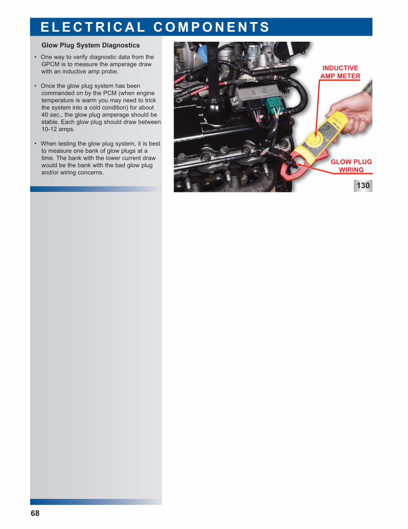
• One way to verify diagnostic data from theGPCM is to measure the amperage drawwith an inductive amp probe.
• Once the glow plug system has been commanded on by the PCM (when enginetemperature is warm you may need to trickthe system into a cold condition) for about40 sec., the glow plug amperage should bestable. Each glow plug should draw between10-12 amps.
• When testing the glow plug system, it is bestto measure one bank of glow plugs at atime. The bank with the lower current drawwould be the bank with the bad glow plugand/or wiring concerns.
E L E C T R I C A L C O M P O N E N T S
68
Glow Plug System Diagnostics
GLOW PLUGWIRING
INDUCTIVEAMP METER
131
132
133
Injector: Removal
• Remove the fuel filter lid and lift the filter element out of the housing and discard inthe appropriate location.
• To avoid fuel spills, use a suction gun or simular device to remove the remaining fuelfrom the fuel filter housing.
• Install the new filter and tighten the fuel filterlid to the specified torque.
• Note: Before starting the vehicle, cyclethe key to the on position and let the fuelpump run a full cycle 3 times to ensurethe fuel filter housing is full of fuel beforestarting the vehicle.
Fuel Filter: Replacement
Oil Filter: Replacement
U N I Q U E S E R V I C E P R O C E D U R E S
69
• First loosen the oil filter cap which will openthe oil filter drain and allow the oil from thefilter housing to drain into the crankcase.
• Drain the oil from the oil pan.
• After all of the oil has drained from the oilpan remove the oil filter and discard it in theappropriate location.
• Note: The oil filter snaps into the oil filterlid.
• Install the new oil filter element and tightenthe oil filter cap to the recommended torque.This will close the oil filter drain.
• Refill crankcase with correct volume of recommended oil.
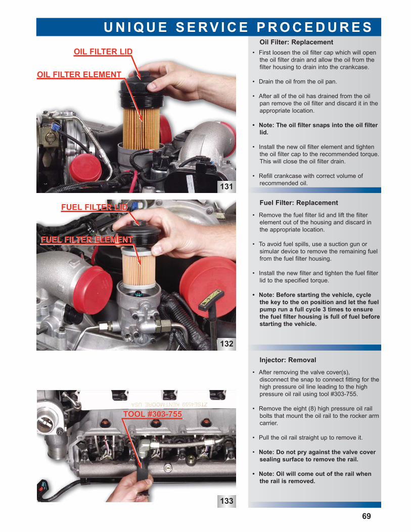
• After removing the valve cover(s), disconnect the snap to connect fitting for thehigh pressure oil line leading to the highpressure oil rail using tool #303-755.
• Remove the eight (8) high pressure oil railbolts that mount the oil rail to the rocker armcarrier.
• Pull the oil rail straight up to remove it.
• Note: Do not pry against the valve coversealing surface to remove the rail.
• Note: Oil will come out of the rail whenthe rail is removed.
OIL FILTER ELEMENT
OIL FILTER LID
FUEL FILTER LIDFUEL FILTER LID
FUEL FILTER ELEMENTFUEL FILTER ELEMENT
TOOL #303-755TOOL #303-755
135
136
Injector O-ring: Replacement
Injector Removal: cont.
Injector Removal: cont.
U N I Q U E S E R V I C E P R O C E D U R E S
70
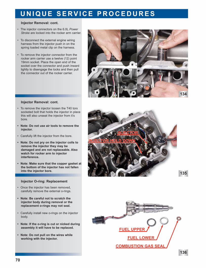
• The injector connectors on the 6.0L PowerStroke are locked into the rocker arm carrier.
• To disconnect the external engine wiring harness from the injector push in on thespring loaded metal clip on the harness.
• To remove the injector connector from therocker arm carrier use a twelve (12) point19mm socket. Place the open end of thesocket over the connector and push inwardlightly to disengage the locks and then pullthe connector out of the rocker carrier.
• To remove the injector loosen the T40 torxsocketed bolt that holds the injector in placethis will also unseat the injector from it’sbore.
• Note: Do not use air tools to remove theinjector.
• Carefully lift the injector from the bore.
• Note: Do not pry on the injector coils toremove the injector they may be damaged and are not replaceable. Alsowatch for rocker arm to injector interference.
• Note: Make sure that the copper gasket atthe bottom of the injector has not falleninto the injector bore.
• Once the injector has been removed, carefully remove the external o-rings.
• Note: Be careful not to scratch the injector body during removal or thereplacement o-rings may not seal.
• Carefully install new o-rings on the injectorbody.
• Note: If the o-ring is cut or nicked duringassembly it will have to be replaced.
• Note: Do not pull on the wires whileworking with the injector.
134
INJECTORINJECTOR
INJECTOR HOLD DOWNINJECTOR HOLD DOWN
FUEL UPPER
FUEL LOWER
COMBUSTION GAS SEAL
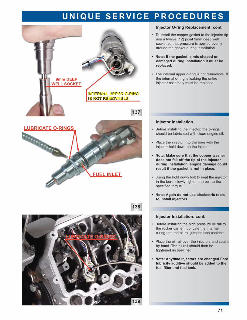
137
138
139
Injector Installation: cont.
Injector Installation
Injector O-ring Replacement: cont.
U N I Q U E S E R V I C E P R O C E D U R E S
71
• To install the copper gasket to the injector tipuse a twelve (12) point 9mm deep well socket so that pressure is applied evenlyaround the gasket during installation.
• Note: If the gasket is mis-shaped or damaged during installation it must bereplaced.
• The internal upper o-ring is not removable. Ifthe internal o-ring is leaking the entire injector assembly must be replaced.
• Before installing the injector, the o-ringsshould be lubricated with clean engine oil.
• Place the injector into the bore with theinjector hold down on the injector.
• Note: Make sure that the copper washerdoes not fall off the tip of the injectorduring installation, engine damage couldresult if the gasket is not in place.
• Using the hold down bolt to seat the injectorin the bore, slowly tighten the bolt to thespecified torque.
• Note: Again do not use air/electric toolsto install injectors.
• Before installing the high pressure oil rail tothe rocker carrier, lubricate the internal o-ring that the oil rail jumper tube contacts.
• Place the oil rail over the injectors and seat itby hand. The oil rail should then be tightened as specified.
• Note: Anytime injectors are changed Fordlubricity additive should be added to thefuel filter and fuel tank.
WELL SOCKET9mm DEEP
INTERNAL UPPER O-RINGINTERNAL UPPER O-RINGIS NOT REMOVABLEIS NOT REMOVABLE
LUBRICATE O-RINGS
FUEL INLET
LUBRICATE O-RINGSLUBRICATE O-RINGS
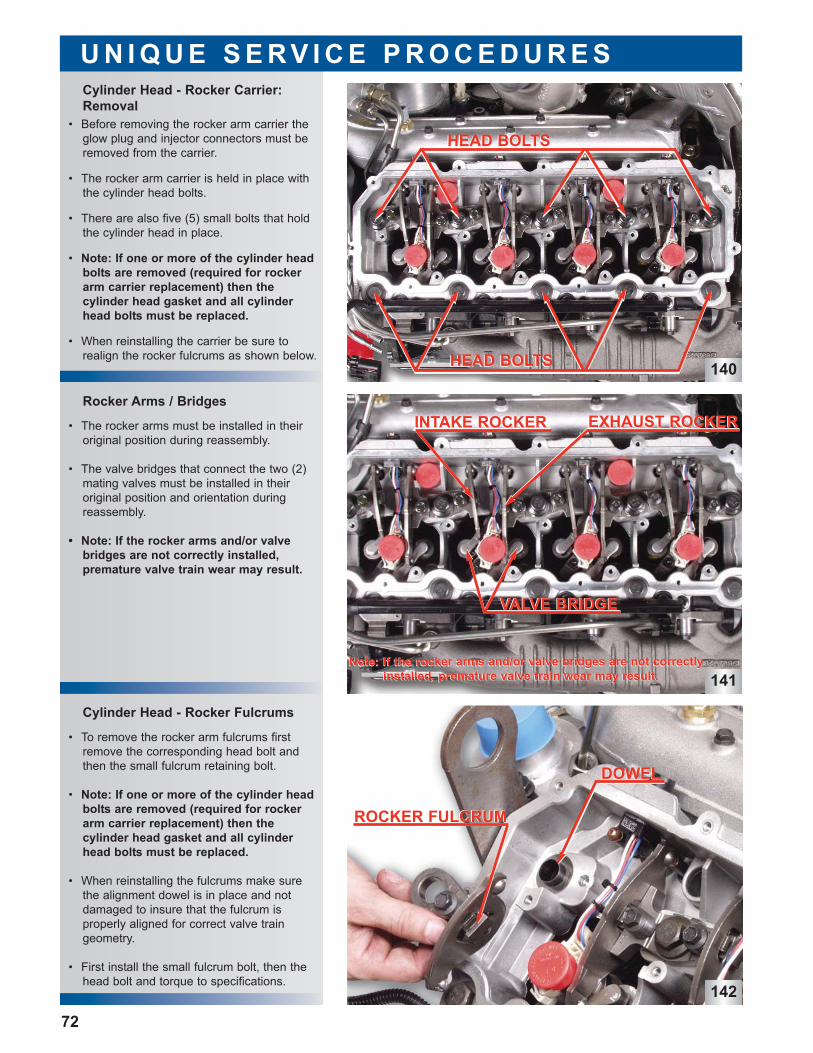
140
141
142
Cylinder Head - Rocker Fulcrums
Rocker Arms / Bridges
Cylinder Head - Rocker Carrier:Removal
U N I Q U E S E R V I C E P R O C E D U R E S
72
• Before removing the rocker arm carrier theglow plug and injector connectors must beremoved from the carrier.
• The rocker arm carrier is held in place withthe cylinder head bolts.
• There are also five (5) small bolts that holdthe cylinder head in place.
• Note: If one or more of the cylinder headbolts are removed (required for rockerarm carrier replacement) then the cylinder head gasket and all cylinderhead bolts must be replaced.
• When reinstalling the carrier be sure torealign the rocker fulcrums as shown below.
• The rocker arms must be installed in theiroriginal position during reassembly.
• The valve bridges that connect the two (2)mating valves must be installed in their original position and orientation duringreassembly.
• Note: If the rocker arms and/or valvebridges are not correctly installed, premature valve train wear may result.
• To remove the rocker arm fulcrums firstremove the corresponding head bolt andthen the small fulcrum retaining bolt.
• Note: If one or more of the cylinder headbolts are removed (required for rockerarm carrier replacement) then the cylinder head gasket and all cylinderhead bolts must be replaced.
• When reinstalling the fulcrums make surethe alignment dowel is in place and notdamaged to insure that the fulcrum is properly aligned for correct valve traingeometry.
• First install the small fulcrum bolt, then thehead bolt and torque to specifications.
HEAD BOLTSHEAD BOLTS
HEAD BOLTSHEAD BOLTS
Note: If the rocker arms and/or valve bridges are not correctlyNote: If the rocker arms and/or valve bridges are not correctlyinstalled, premature valve train wear may result.installed, premature valve train wear may result.
INTAKE ROCKERINTAKE ROCKER EXHAUST ROCKEREXHAUST ROCKER
VALVE BRIDGEVALVE BRIDGE
DOWELDOWEL
ROCKER FULCRUMROCKER FULCRUM
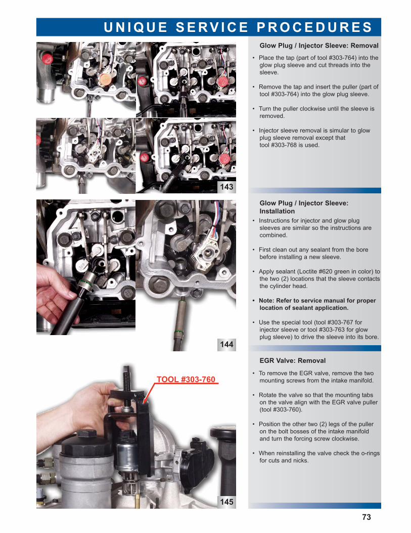
143
145
EGR Valve: Removal
Glow Plug / Injector Sleeve:Installation
Glow Plug / Injector Sleeve: Removal
U N I Q U E S E R V I C E P R O C E D U R E S
144
73
• Place the tap (part of tool #303-764) into theglow plug sleeve and cut threads into thesleeve.
• Remove the tap and insert the puller (part oftool #303-764) into the glow plug sleeve.
• Turn the puller clockwise until the sleeve isremoved.
• Injector sleeve removal is simular to glowplug sleeve removal except that tool #303-768 is used.
• Instructions for injector and glow plugsleeves are similar so the instructions arecombined.
• First clean out any sealant from the borebefore installing a new sleeve.
• Apply sealant (Loctite #620 green in color) tothe two (2) locations that the sleeve contactsthe cylinder head.
• Note: Refer to service manual for properlocation of sealant application.
• Use the special tool (tool #303-767 for injector sleeve or tool #303-763 for glowplug sleeve) to drive the sleeve into its bore.
• To remove the EGR valve, remove the twomounting screws from the intake manifold.
• Rotate the valve so that the mounting tabson the valve align with the EGR valve puller(tool #303-760).
• Position the other two (2) legs of the pulleron the bolt bosses of the intake manifoldand turn the forcing screw clockwise.
• When reinstalling the valve check the o-ringsfor cuts and nicks.
TOOL #303-760
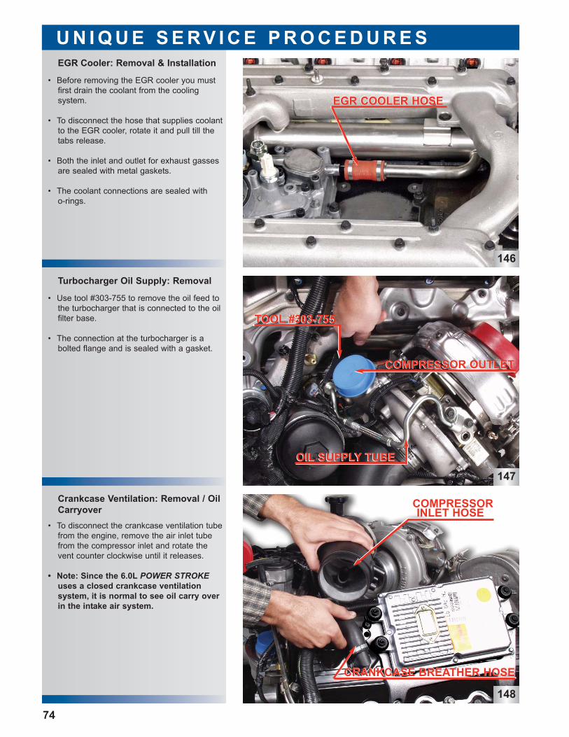
146
147
148
Crankcase Ventilation: Removal / OilCarryover
Turbocharger Oil Supply: Removal
EGR Cooler: Removal & Installation
U N I Q U E S E R V I C E P R O C E D U R E S
• Before removing the EGR cooler you mustfirst drain the coolant from the cooling system.
• To disconnect the hose that supplies coolantto the EGR cooler, rotate it and pull till thetabs release.
• Both the inlet and outlet for exhaust gassesare sealed with metal gaskets.
• The coolant connections are sealed with o-rings.
• Use tool #303-755 to remove the oil feed tothe turbocharger that is connected to the oilfilter base.
• The connection at the turbocharger is a bolted flange and is sealed with a gasket.
74
• To disconnect the crankcase ventilation tubefrom the engine, remove the air inlet tubefrom the compressor inlet and rotate thevent counter clockwise until it releases.
• Note: Since the 6.0L POWER STROKEuses a closed crankcase ventilation system, it is normal to see oil carry overin the intake air system.
EGR COOLER HOSEEGR COOLER HOSE
TOOL #303-755TOOL #303-755
COMPRESSOR OUTLETCOMPRESSOR OUTLET
OIL SUPPLY TUBEOIL SUPPLY TUBE
CRANKCASE BREATHER HOSECRANKCASE BREATHER HOSE
COMPRESSORINLET HOSE
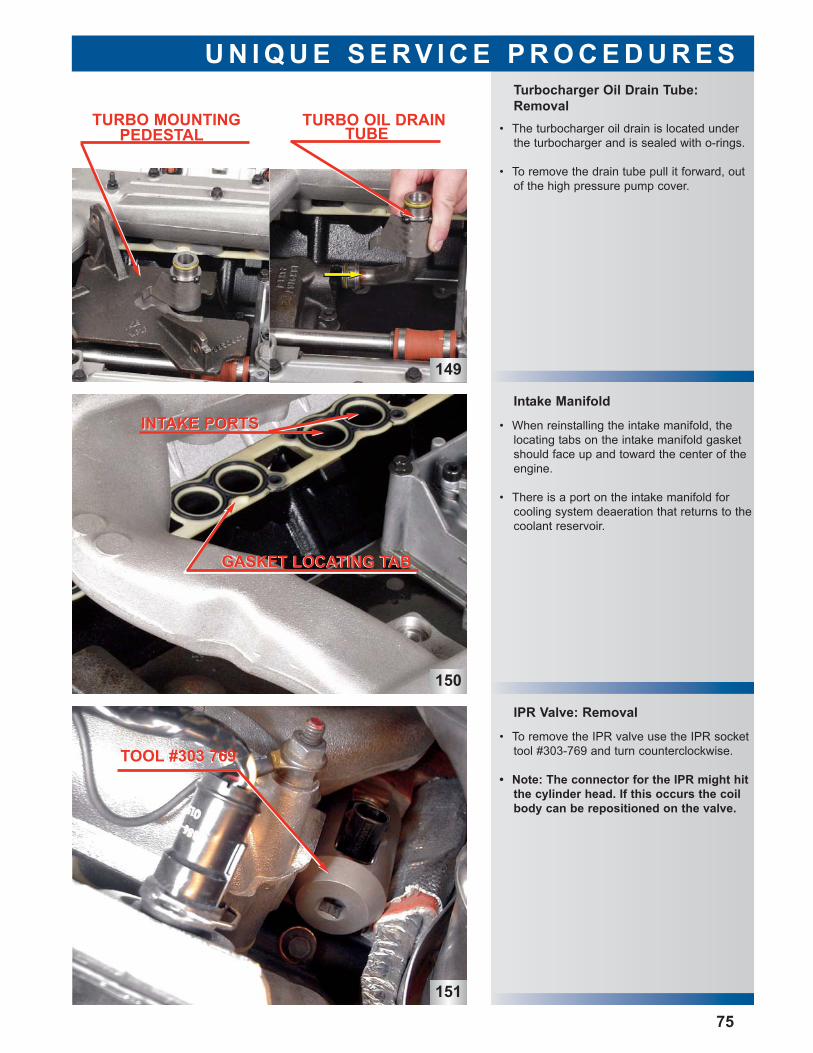
150
151
IPR Valve: Removal • To remove the IPR valve use the IPR socket
tool #303-769 and turn counterclockwise.
• Note: The connector for the IPR might hitthe cylinder head. If this occurs the coilbody can be repositioned on the valve.
Intake Manifold
Turbocharger Oil Drain Tube:Removal
U N I Q U E S E R V I C E P R O C E D U R E S
149
75
• The turbocharger oil drain is located underthe turbocharger and is sealed with o-rings.
• To remove the drain tube pull it forward, outof the high pressure pump cover.
• When reinstalling the intake manifold, thelocating tabs on the intake manifold gasketshould face up and toward the center of theengine.
• There is a port on the intake manifold forcooling system deaeration that returns to thecoolant reservoir.
GASKET LOCATING TABGASKET LOCATING TAB
INTAKE PORTSINTAKE PORTS
TURBO MOUNTINGPEDESTAL
TURBO OIL DRAINTUBE
TOOL #303 769TOOL #303 769
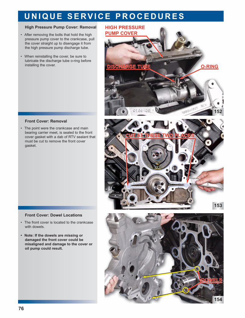
152
153
154
Front Cover: Dowel Locations
Front Cover: Removal
High Pressure Pump Cover: Removal
U N I Q U E S E R V I C E P R O C E D U R E S
• After removing the bolts that hold the highpressure pump cover to the crankcase, pullthe cover straight up to disengage it fromthe high pressure pump discharge tube.
• When reinstalling the cover, be sure to lubricate the discharge tube o-ring beforeinstalling the cover.
• The point were the crankcase and mainbearing carrier meet, is sealed to the frontcover gasket with a dab of RTV sealant thatmust be cut to remove the front cover gasket.
• The front cover is located to the crankcasewith dowels.
• Note: If the dowels are missing or damaged the front cover could be misaligned and damage to the cover oroil pump could result.
76
CUT AT THESE TWO PLACESCUT AT THESE TWO PLACES
DOWELSDOWELS
HIGH PRESSUREPUMP COVERHIGH PRESSUREPUMP COVER
DISCHARGE TUBEDISCHARGE TUBE O-RING
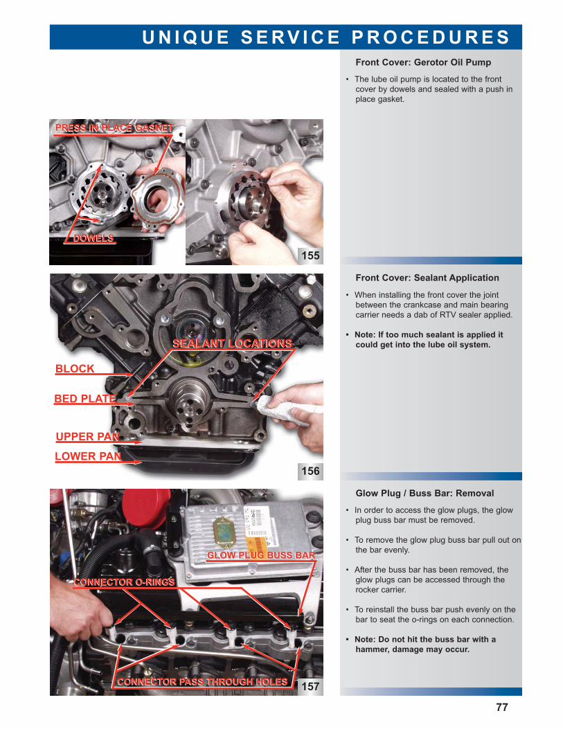
156
157
Glow Plug / Buss Bar: Removal
• In order to access the glow plugs, the glowplug buss bar must be removed.
• To remove the glow plug buss bar pull out onthe bar evenly.
• After the buss bar has been removed, theglow plugs can be accessed through therocker carrier.
• To reinstall the buss bar push evenly on thebar to seat the o-rings on each connection.
• Note: Do not hit the buss bar with a hammer, damage may occur.
Front Cover: Sealant Application
Front Cover: Gerotor Oil Pump
U N I Q U E S E R V I C E P R O C E D U R E S
• When installing the front cover the jointbetween the crankcase and main bearingcarrier needs a dab of RTV sealer applied.
• Note: If too much sealant is applied itcould get into the lube oil system.
• The lube oil pump is located to the frontcover by dowels and sealed with a push inplace gasket.
155
77
PRESS IN PLACE GASKETPRESS IN PLACE GASKET
DOWELSDOWELS
BLOCK
BED PLATEBED PLATE
UPPER PANUPPER PAN
LOWER PANLOWER PAN
SEALANT LOCATIONSSEALANT LOCATIONS
GLOW PLUG BUSS BARGLOW PLUG BUSS BAR
CONNECTOR PASS THROUGH HOLESCONNECTOR PASS THROUGH HOLES
CONNECTOR O-RINGSCONNECTOR O-RINGS
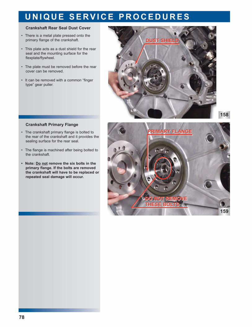
158
159
• The crankshaft primary flange is bolted tothe rear of the crankshaft and it provides thesealing surface for the rear seal.
• The flange is machined after being bolted tothe crankshaft.
• Note: Do not remove the six bolts in theprimary flange. If the bolts are removedthe crankshaft will have to be replaced orrepeated seal damage will occur.
• There is a metal plate pressed onto the primary flange of the crankshaft.
• This plate acts as a dust shield for the rearseal and the mounting surface for the flexplate/flywheel.
• The plate must be removed before the rearcover can be removed.
• It can be removed with a common “fingertype” gear puller.
Crankshaft Primary Flange
Crankshaft Rear Seal Dust Cover
U N I Q U E S E R V I C E P R O C E D U R E S
78
DUST SHIELDDUST SHIELD
PRIMARY FLANGEPRIMARY FLANGE
DO NOT REMOVETHESE BOLTSDO NOT REMOVETHESE BOLTS
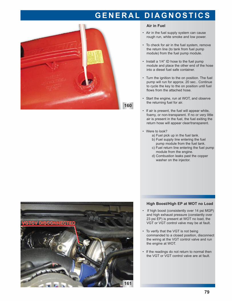
160
161
High Boost/High EP at WOT no Load
• If high boost (consistently over 14 psi MGP)and high exhaust pressure (constantly over23 psi EP) is present at WOT no load, theVGT or VGT control valve may be at fault.
• To verify that the VGT is not being commanded to a closed position, disconnectthe wiring at the VGT control valve and runthe engine at WOT.
• If the readings do not return to normal thenthe VGT or VGT control valve are at fault.
Air in Fuel
G E N E R A L D I A G N O S T I C S
79
• Air in the fuel supply system can causerough run, white smoke and low power.
• To check for air in the fuel system, removethe return line (to tank from fuel pump module) from the fuel pump module.
• Install a 1/4” ID hose to the fuel pump module and place the other end of the hoseinto a diesel fuel safe container.
• Turn the ignition to the on position. The fuelpump will run for approx. 20 sec.. Continueto cycle the key to the on position until fuelflows from the attached hose.
• Start the engine, run at WOT, and observethe returning fuel for air.
• If air is present, the fuel will appear white,foamy, or non-transparent. If no or very littleair is present in the fuel, the fuel exiting thereturn hose will appear clear/transparent.
• Were to look?a) Fuel pick up in the fuel tank.b) Fuel supply line entering the fuel
pump module from the fuel tank.c) Fuel return line entering the fuel pump
module from the engine.d) Combustion leaks past the copper
washer on the injector.
VGTCV DISCONNECTEDVGTCV DISCONNECTED
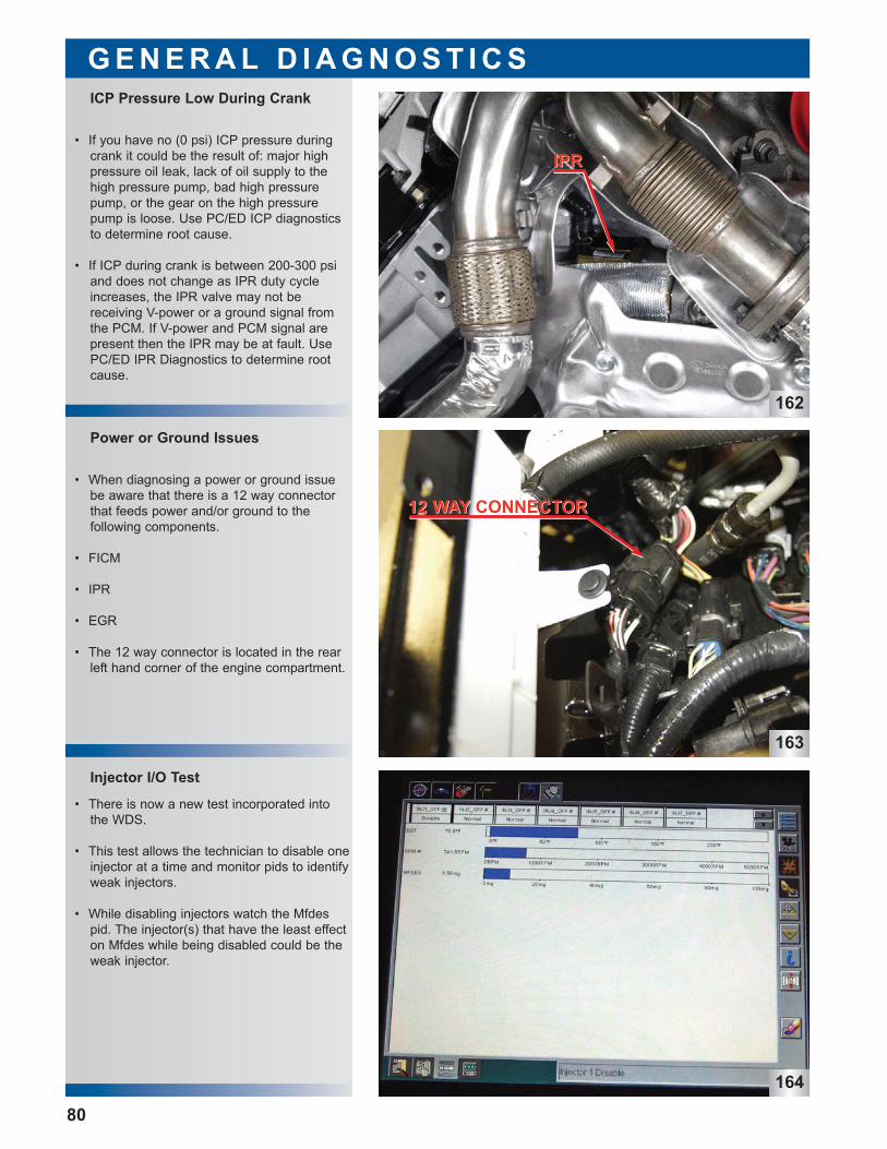
162
163
164
• There is now a new test incorporated intothe WDS.
• This test allows the technician to disable oneinjector at a time and monitor pids to identifyweak injectors.
• While disabling injectors watch the Mfdespid. The injector(s) that have the least effecton Mfdes while being disabled could be theweak injector.
• When diagnosing a power or ground issuebe aware that there is a 12 way connectorthat feeds power and/or ground to the following components.
• FICM
• IPR
• EGR
• The 12 way connector is located in the rearleft hand corner of the engine compartment.
• If you have no (0 psi) ICP pressure duringcrank it could be the result of: major highpressure oil leak, lack of oil supply to thehigh pressure pump, bad high pressurepump, or the gear on the high pressurepump is loose. Use PC/ED ICP diagnosticsto determine root cause.
• If ICP during crank is between 200-300 psiand does not change as IPR duty cycleincreases, the IPR valve may not be receiving V-power or a ground signal fromthe PCM. If V-power and PCM signal arepresent then the IPR may be at fault. UsePC/ED IPR Diagnostics to determine rootcause.
Injector I/O Test
Power or Ground Issues
ICP Pressure Low During Crank
G E N E R A L D I A G N O S T I C S
80
IPRIPR
12 WAY CONNECTOR12 WAY CONNECTOR
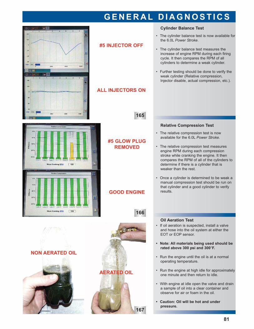
166
167
Oil Aeration Test • If oil aeration is suspected, install a valve
and hose into the oil system at either theEOT or EOP sensor.
• Note: All materials being used should berated above 300 psi and 300°F.
• Run the engine until the oil is at a normaloperating temperature.
• Run the engine at high idle for approximatelyone minute and then return to idle.
• With engine at idle open the valve and draina sample of oil into a clear container andobserve for air or foam in the oil.
• Caution: Oil will be hot and under pressure.
• The relative compression test is now available for the 6.0L Power Stroke.
• The relative compression test measuresengine RPM during each compressionstroke while cranking the engine. It thencompares the RPM of all of the cylinders todetermine if there is a cylinder that is weaker than the rest.
• Once a cylinder is determined to be weak amanual compression test should be run onthat cylinder and a good cylinder to verifyresults.
• The cylinder balance test is now available forthe 6.0L Power Stroke.
• The cylinder balance test measures theincrease of engine RPM during each firingcycle. It then compares the RPM of all cylinders to determine a weak cylinder.
• Further testing should be done to verify theweak cylinder (Relative compression,Injector disable, actual compression, etc.).
Relative Compression Test
Cylinder Balance Test
G E N E R A L D I A G N O S T I C S
81
165
#5 INJECTOR OFF
ALL INJECTORS ON
#5 GLOW PLUGREMOVED
GOOD ENGINE
AERATED OIL
NON AERATED OIL
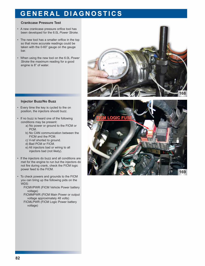
168
169
• Every time the key is cycled to the on position, the injectors should buzz.
• If no buzz is heard one of the following conditions may be present:
a) No power or ground to the FICM orPCM.
b) No CAN communication between theFICM and the PCM.
c) V-ref shorted to ground.d) Bad PCM or FICM.e) All injectors bad or wiring to all
injectors bad (not likely).
• If the injectors do buzz and all conditions aremet for the engine to run but the injectors donot fire during crank, check the FICM logicpower feed to the FICM.
• To check powers and grounds to the FICMyou can bring up the following pids on theWDS:
FICMVPWR (FICM Vehicle Power batteryvoltage)
FICMMPWR (FICM Main Power or outputvoltage approximately 48 volts)
FICMLPWR (FICM Logic Power batteryvoltage)
• A new crankcase pressure orifice tool hasbeen developed for the 6.0L Power Stroke.
• The new tool has a smaller orifice in the topso that more accurate readings could betaken with the 0-60” gauge on the gaugebar.
• When using the new tool on the 6.0L PowerStroke the maximum reading for a goodengine is 8” of water.
Crankcase Pressure Test
G E N E R A L D I A G N O S T I C S
82
Injector Buzz/No Buzz
FICM LOGIC FUSEFICM LOGIC FUSE
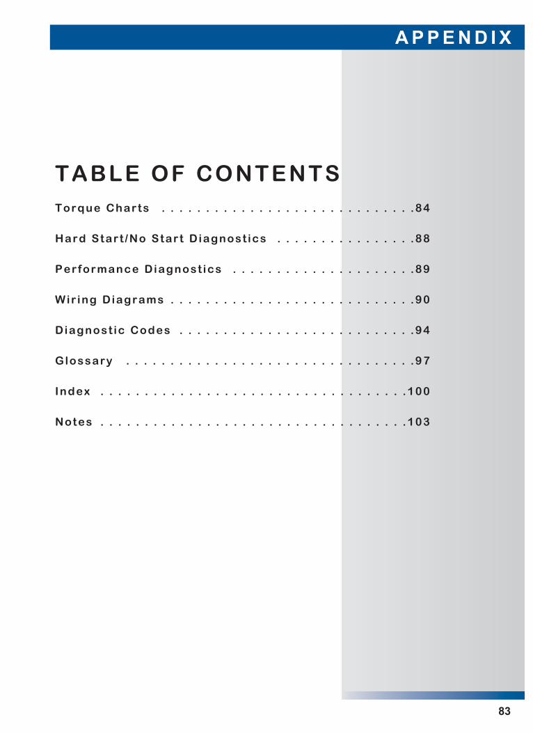
A P P E N D I X
83
TABLE OF CONTENTSTorque Charts . . . . . . . . . . . . . . . . . . . . . . . . . . . . .84
Hard Start /No Start Diagnost ics . . . . . . . . . . . . . . . .88
Performance Diagnost ics . . . . . . . . . . . . . . . . . . . . .89
Wir ing Diagrams . . . . . . . . . . . . . . . . . . . . . . . . . . . .90
Diagnost ic Codes . . . . . . . . . . . . . . . . . . . . . . . . . . .94
Glossary . . . . . . . . . . . . . . . . . . . . . . . . . . . . . . . . .97
Index . . . . . . . . . . . . . . . . . . . . . . . . . . . . . . . . . . .100
Notes . . . . . . . . . . . . . . . . . . . . . . . . . . . . . . . . . . .103
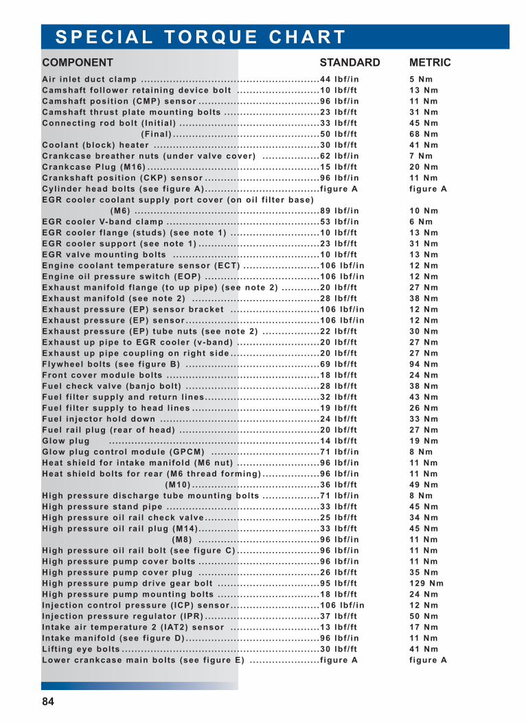
S P E C I A L T O R Q U E C H A R T
84
Air inlet duct c lamp . . . . . . . . . . . . . . . . . . . . . . . . . . . . . . . . . . . . . . . . . . . . . . . . . . . . . . . .44 lbf / in 5 NmCamshaft fol lower retaining device bolt . . . . . . . . . . . . . . . . . . . . . . . . . .10 lbf / ft 13 NmCamshaft posit ion (CMP) sensor . . . . . . . . . . . . . . . . . . . . . . . . . . . . . . . . . . . . . .96 lbf / in 11 NmCamshaft thrust plate mounting bolts . . . . . . . . . . . . . . . . . . . . . . . . . . . . . .23 lbf / ft 31 NmConnect ing rod bolt ( In i t ia l ) . . . . . . . . . . . . . . . . . . . . . . . . . . . . . . . . . . . . . . . . . . . .33 lbf / ft 45 Nm
(Final ) . . . . . . . . . . . . . . . . . . . . . . . . . . . . . . . . . . . . . . . . . . . . . .50 lbf / ft 68 NmCoolant (block) heater . . . . . . . . . . . . . . . . . . . . . . . . . . . . . . . . . . . . . . . . . . . . . . . . . . . .30 lbf / ft 41 NmCrankcase breather nuts (under valve cover) . . . . . . . . . . . . . . . . . .62 lbf / in 7 NmCrankcase Plug (M16) . . . . . . . . . . . . . . . . . . . . . . . . . . . . . . . . . . . . . . . . . . . . . . . . . . . . . .15 lbf / ft 20 NmCrankshaft posit ion (CKP) sensor . . . . . . . . . . . . . . . . . . . . . . . . . . . . . . . . . . . .96 lbf / in 11 NmCyl inder head bolts (see f igure A) . . . . . . . . . . . . . . . . . . . . . . . . . . . . . . . . . . . . f igure A f igure AEGR cooler coolant supply port cover (on oi l f i l ter base)
(M6) . . . . . . . . . . . . . . . . . . . . . . . . . . . . . . . . . . . . . . . . . . . . . . . . . . . . . . . . . .89 lbf / in 10 NmEGR cooler V-band clamp . . . . . . . . . . . . . . . . . . . . . . . . . . . . . . . . . . . . . . . . . . . . . . . .53 lbf / in 6 NmEGR cooler f lange (studs) (see note 1) . . . . . . . . . . . . . . . . . . . . . . . . . . . .10 lbf / ft 13 NmEGR cooler support (see note 1) . . . . . . . . . . . . . . . . . . . . . . . . . . . . . . . . . . . . . .23 lbf / ft 31 NmEGR valve mounting bolts . . . . . . . . . . . . . . . . . . . . . . . . . . . . . . . . . . . . . . . . . . . . . .10 lbf / ft 13 NmEngine coolant temperature sensor (ECT) . . . . . . . . . . . . . . . . . . . . . . . .106 lbf / in 12 NmEngine oi l pressure switch (EOP) . . . . . . . . . . . . . . . . . . . . . . . . . . . . . . . . . . . .106 lbf / in 12 NmExhaust manifold f lange ( to up pipe) (see note 2) . . . . . . . . . . . .20 lbf / ft 27 NmExhaust manifold (see note 2) . . . . . . . . . . . . . . . . . . . . . . . . . . . . . . . . . . . . . . . .28 lbf / ft 38 NmExhaust pressure (EP) sensor bracket . . . . . . . . . . . . . . . . . . . . . . . . . . . .106 lbf / in 12 NmExhaust pressure (EP) sensor . . . . . . . . . . . . . . . . . . . . . . . . . . . . . . . . . . . . . . . . . .106 lbf / in 12 NmExhaust pressure (EP) tube nuts (see note 2) . . . . . . . . . . . . . . . . . .22 lbf / ft 30 NmExhaust up pipe to EGR cooler (v-band) . . . . . . . . . . . . . . . . . . . . . . . . . .20 lbf / ft 27 NmExhaust up pipe coupl ing on r ight s ide . . . . . . . . . . . . . . . . . . . . . . . . . . . .20 lbf / ft 27 NmFlywheel bolts (see f igure B) . . . . . . . . . . . . . . . . . . . . . . . . . . . . . . . . . . . . . . . . . .69 lbf / ft 94 NmFront cover module bolts . . . . . . . . . . . . . . . . . . . . . . . . . . . . . . . . . . . . . . . . . . . . . . . .18 lbf / ft 24 NmFuel check valve (banjo bolt ) . . . . . . . . . . . . . . . . . . . . . . . . . . . . . . . . . . . . . . . . . .28 lbf / ft 38 NmFuel f i l ter supply and return l ines . . . . . . . . . . . . . . . . . . . . . . . . . . . . . . . . . . . .32 lbf / ft 43 NmFuel f i l ter supply to head l ines . . . . . . . . . . . . . . . . . . . . . . . . . . . . . . . . . . . . . . . .19 lbf / ft 26 NmFuel injector hold down . . . . . . . . . . . . . . . . . . . . . . . . . . . . . . . . . . . . . . . . . . . . . . . . . .24 lbf / ft 33 NmFuel rai l p lug (rear of head) . . . . . . . . . . . . . . . . . . . . . . . . . . . . . . . . . . . . . . . . . . . .20 lbf / ft 27 NmGlow plug . . . . . . . . . . . . . . . . . . . . . . . . . . . . . . . . . . . . . . . . . . . . . . . . . . . . . . . . . . . . . . . . . .14 lbf / ft 19 NmGlow plug control module (GPCM) . . . . . . . . . . . . . . . . . . . . . . . . . . . . . . . . . .71 lbf / in 8 NmHeat shield for intake manifold (M6 nut) . . . . . . . . . . . . . . . . . . . . . . . . . .96 lbf / in 11 NmHeat shield bolts for rear (M6 thread forming) . . . . . . . . . . . . . . . . . .96 lbf / in 11 Nm
(M10) . . . . . . . . . . . . . . . . . . . . . . . . . . . . . . . . . . . . . . . .36 lbf / ft 49 NmHigh pressure discharge tube mounting bolts . . . . . . . . . . . . . . . . . .71 lbf / in 8 NmHigh pressure stand pipe . . . . . . . . . . . . . . . . . . . . . . . . . . . . . . . . . . . . . . . . . . . . . . . .33 lbf / ft 45 NmHigh pressure oi l ra i l check valve . . . . . . . . . . . . . . . . . . . . . . . . . . . . . . . . . . . .25 lbf / ft 34 NmHigh pressure oi l ra i l p lug (M14) . . . . . . . . . . . . . . . . . . . . . . . . . . . . . . . . . . . . . .33 lbf / ft 45 Nm
(M8) . . . . . . . . . . . . . . . . . . . . . . . . . . . . . . . . . . . . . .96 lbf / in 11 NmHigh pressure oi l ra i l bol t (see f igure C) . . . . . . . . . . . . . . . . . . . . . . . . . .96 lbf / in 11 NmHigh pressure pump cover bolts . . . . . . . . . . . . . . . . . . . . . . . . . . . . . . . . . . . . . .96 lbf / in 11 NmHigh pressure pump cover plug . . . . . . . . . . . . . . . . . . . . . . . . . . . . . . . . . . . . . .26 lbf / ft 35 NmHigh pressure pump drive gear bolt . . . . . . . . . . . . . . . . . . . . . . . . . . . . . . . .95 lbf / ft 129 NmHigh pressure pump mounting bolts . . . . . . . . . . . . . . . . . . . . . . . . . . . . . . . .18 lbf / ft 24 NmInject ion control pressure ( ICP) sensor . . . . . . . . . . . . . . . . . . . . . . . . . . . .106 lbf / in 12 NmInject ion pressure regulator ( IPR) . . . . . . . . . . . . . . . . . . . . . . . . . . . . . . . . . . . .37 lbf / ft 50 NmIntake air temperature 2 ( IAT2) sensor . . . . . . . . . . . . . . . . . . . . . . . . . . . .13 lbf / ft 17 NmIntake manifold (see f igure D) . . . . . . . . . . . . . . . . . . . . . . . . . . . . . . . . . . . . . . . . . .96 lbf / in 11 NmLift ing eye bolts . . . . . . . . . . . . . . . . . . . . . . . . . . . . . . . . . . . . . . . . . . . . . . . . . . . . . . . . . . . . . .30 lbf / ft 41 NmLower crankcase main bolts (see f igure E) . . . . . . . . . . . . . . . . . . . . . . f igure A f igure A
COMPONENT STANDARD METRIC
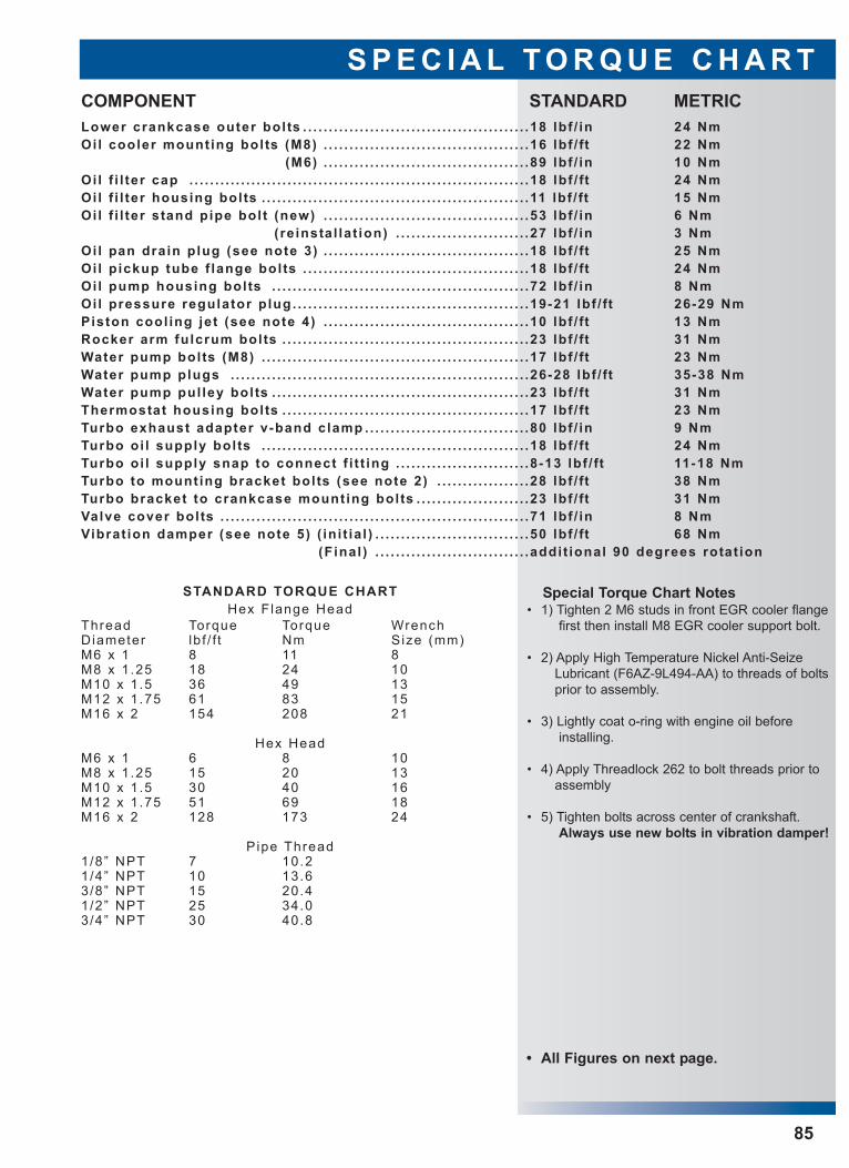
S P E C I A L T O R Q U E C H A R T
85
Lower crankcase outer bolts . . . . . . . . . . . . . . . . . . . . . . . . . . . . . . . . . . . . . . . . . . . .18 lbf / in 24 NmOil cooler mounting bolts (M8) . . . . . . . . . . . . . . . . . . . . . . . . . . . . . . . . . . . . . . . .16 lbf / ft 22 Nm
(M6) . . . . . . . . . . . . . . . . . . . . . . . . . . . . . . . . . . . . . . . .89 lbf / in 10 NmOil f i l ter cap . . . . . . . . . . . . . . . . . . . . . . . . . . . . . . . . . . . . . . . . . . . . . . . . . . . . . . . . . . . . . . . . . .18 lbf / ft 24 NmOil f i l ter housing bolts . . . . . . . . . . . . . . . . . . . . . . . . . . . . . . . . . . . . . . . . . . . . . . . . . . . .11 lbf / ft 15 NmOil f i l ter stand pipe bolt (new) . . . . . . . . . . . . . . . . . . . . . . . . . . . . . . . . . . . . . . . .53 lbf / in 6 Nm
(reinstal lat ion) . . . . . . . . . . . . . . . . . . . . . . . . . .27 lbf / in 3 NmOil pan drain plug (see note 3) . . . . . . . . . . . . . . . . . . . . . . . . . . . . . . . . . . . . . . . .18 lbf / ft 25 NmOil pickup tube f lange bolts . . . . . . . . . . . . . . . . . . . . . . . . . . . . . . . . . . . . . . . . . . . .18 lbf / ft 24 NmOil pump housing bolts . . . . . . . . . . . . . . . . . . . . . . . . . . . . . . . . . . . . . . . . . . . . . . . . . .72 lbf / in 8 NmOil pressure regulator plug . . . . . . . . . . . . . . . . . . . . . . . . . . . . . . . . . . . . . . . . . . . . . .19-21 lbf / ft 26-29 NmPiston cool ing jet (see note 4) . . . . . . . . . . . . . . . . . . . . . . . . . . . . . . . . . . . . . . . .10 lbf / ft 13 NmRocker arm fulcrum bolts . . . . . . . . . . . . . . . . . . . . . . . . . . . . . . . . . . . . . . . . . . . . . . . .23 lbf / ft 31 NmWater pump bolts (M8) . . . . . . . . . . . . . . . . . . . . . . . . . . . . . . . . . . . . . . . . . . . . . . . . . . . .17 lbf / ft 23 NmWater pump plugs . . . . . . . . . . . . . . . . . . . . . . . . . . . . . . . . . . . . . . . . . . . . . . . . . . . . . . . . . .26-28 lbf / ft 35-38 NmWater pump pul ley bolts . . . . . . . . . . . . . . . . . . . . . . . . . . . . . . . . . . . . . . . . . . . . . . . . . .23 lbf / ft 31 NmThermostat housing bolts . . . . . . . . . . . . . . . . . . . . . . . . . . . . . . . . . . . . . . . . . . . . . . . .17 lbf / ft 23 NmTurbo exhaust adapter v-band clamp . . . . . . . . . . . . . . . . . . . . . . . . . . . . . . . .80 lbf / in 9 NmTurbo oi l supply bolts . . . . . . . . . . . . . . . . . . . . . . . . . . . . . . . . . . . . . . . . . . . . . . . . . . . .18 lbf / ft 24 NmTurbo oi l supply snap to connect f i t t ing . . . . . . . . . . . . . . . . . . . . . . . . . .8-13 lbf / ft 11-18 NmTurbo to mounting bracket bolts (see note 2) . . . . . . . . . . . . . . . . . .28 lbf / ft 38 NmTurbo bracket to crankcase mounting bolts . . . . . . . . . . . . . . . . . . . . . .23 lbf / ft 31 NmValve cover bolts . . . . . . . . . . . . . . . . . . . . . . . . . . . . . . . . . . . . . . . . . . . . . . . . . . . . . . . . . . . .71 lbf / in 8 NmVibrat ion damper (see note 5) ( in i t ia l ) . . . . . . . . . . . . . . . . . . . . . . . . . . . . . .50 lbf / ft 68 Nm
(Final ) . . . . . . . . . . . . . . . . . . . . . . . . . . . . . .addit ional 90 degrees rotat ion
COMPONENT STANDARD METRIC
STANDARD TORQUE CHARTHex F lange Head
Thread Torque Torque WrenchDiameter lb f / f t Nm Size (mm)M6 x 1 8 11 8M8 x 1.25 18 24 10M10 x 1.5 36 49 13M12 x 1.75 61 83 15M16 x 2 154 208 21
Hex HeadM6 x 1 6 8 10M8 x 1.25 15 20 13M10 x 1.5 30 40 16M12 x 1.75 51 69 18M16 x 2 128 173 24
Pipe Thread1/8” NPT 7 10.21/4” NPT 10 13.63/8” NPT 15 20.41/2” NPT 25 34.03/4” NPT 30 40.8
• All Figures on next page.
Special Torque Chart Notes • 1) Tighten 2 M6 studs in front EGR cooler flange
first then install M8 EGR cooler support bolt.
• 2) Apply High Temperature Nickel Anti-SeizeLubricant (F6AZ-9L494-AA) to threads of boltsprior to assembly.
• 3) Lightly coat o-ring with engine oil beforeinstalling.
• 4) Apply Threadlock 262 to bolt threads prior toassembly
• 5) Tighten bolts across center of crankshaft.Always use new bolts in vibration damper!
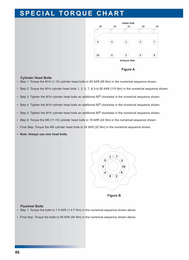
S P E C I A L T O R Q U E C H A R T
86
Cylinder Head Bolts • Step 1: Torque the M14 (1-10) cylinder head bolts to 65 lbf/ft (88 Nm) in the numerical sequence shown.
• Step 2: Torque the M14 cylinder head bolts 1, 3, 5, 7, & 9 to 85 lbf/ft (115 Nm) in the numerical sequence shown.
• Step 3: Tighten the M14 cylinder head bolts an additional 90o clockwise in the numerical sequence shown.
• Step 4: Tighten the M14 cylinder head bolts an additional 90o clockwise in the numerical sequence shown.
• Step 5: Tighten the M14 cylinder head bolts an additional 90o clockwise in the numerical sequence shown.
• Step 6: Torque the M8 (11-15) cylinder head bolts to 18 lbf/ft (24 Nm) in the numerical sequence shown.
• Final Step: Torque the M8 cylinder head bolts to 24 lbf/ft (32 Nm) in the numerical sequence shown.
• Note: Always use new head bolts.
59
8426
731
10
15 14121113Intake Side
Exhaust Side
Figure A
Figure B
Flywheel Bolts • Step 1: Torque the bolts to 1-5 lbf/ft (1.4-7 Nm) in the numerical sequence shown above.
• Final step: Torque the bolts to 69 lbf/ft (94 Nm) in the numerical sequence shown above.
15
9
48 2
6
10
37
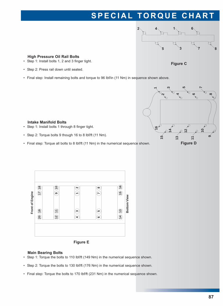
S P E C I A L T O R Q U E C H A R T
87
High Pressure Oil Rail Bolts • Step 1: Install bolts 1, 2 and 3 finger tight.
• Step 2: Press rail down until seated.
• Final step: Install remaining bolts and torque to 96 lbf/in (11 Nm) in sequence shown above.
Figure C
6142
8735
1
2
3
4
5
6
7
89
10
11
12
13
14
15
16
Figure D
Intake Manifold Bolts • Step 1: Install bolts 1 through 8 finger tight.
• Step 2: Torque bolts 9 though 16 to 8 lbf/ft (11 Nm).
• Final step: Torque all bolts to 8 lbf/ft (11 Nm) in the numerical sequence shown.
Fro
nt
of
En
gin
e
1211
109
42019
1 7
23 5
6
1718 8 16
1514
13 Bo
tto
m V
iew
Figure E
Main Bearing Bolts • Step 1: Torque the bolts to 110 lbf/ft (149 Nm) in the numerical sequence shown.
• Step 2: Torque the bolts to 130 lbf/ft (176 Nm) in the numerical sequence shown.
• Final step: Torque the bolts to 170 lbf/ft (231 Nm) in the numerical sequence shown.
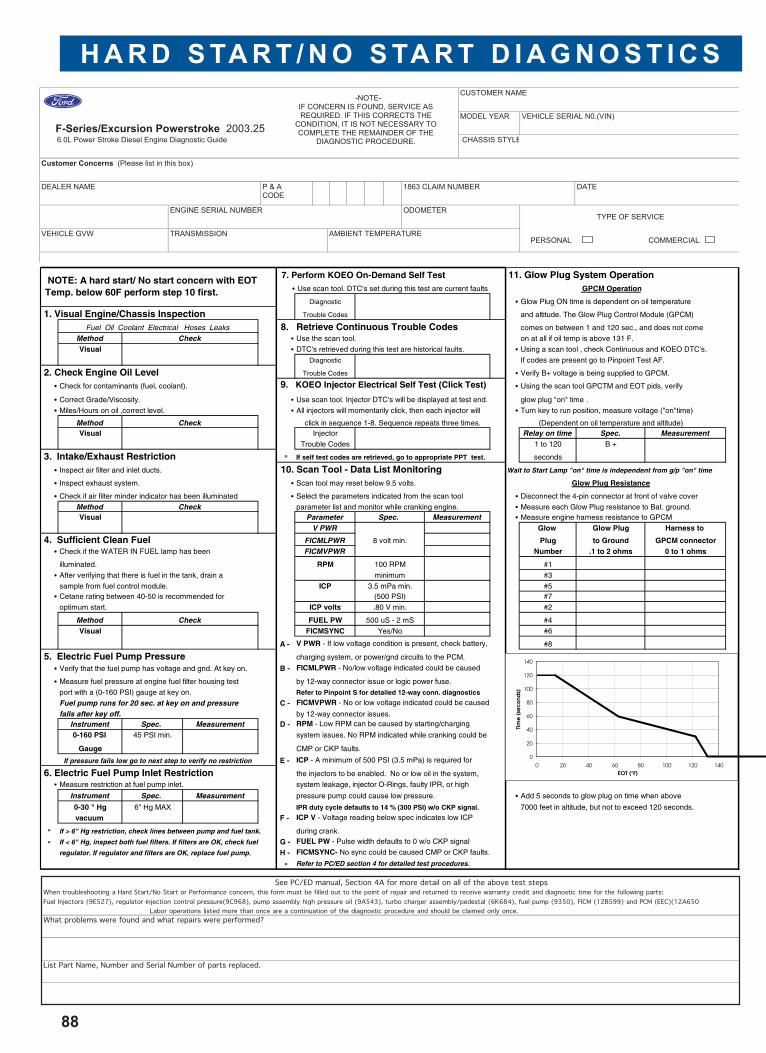
H A R D S TA R T / N O S TA R T D I A G N O S T I C S
88
CUSTOMER NAME
F-Series/Excursion Powerstroke 2003.25
MODEL YEAR VEHICLE SERIAL N0.(VIN)
6.0L Power Stroke Diesel Engine Diagnostic Guide CHASSIS STYLE
Customer Concerns (Please list in this box)
DEALER NAME 1863 CLAIM NUMBER DATE
ENGINE SERIAL NUMBER ODOMETERTYPE OF SERVICE
VEHICLE GVW TRANSMISSION AMBIENT TEMPERATUREPERSONAL COMMERCIAL
P & ACODE
-NOTE-IF CONCERN IS FOUND, SERVICE AS REQUIRED. IF THIS CORRECTS THE
CONDITION, IT IS NOT NECESSARY TO COMPLETE THE REMAINDER OF THE
DIAGNOSTIC PROCEDURE.
7. Perform KOEO On-Demand Self Test 11. Glow Plug System Operation • Use scan tool. DTC's set during this test are current faults GPCM Operation
Diagnostic • Glow Plug ON time is dependent on oil temperature
1. Visual Engine/Chassis Inspection Trouble Codes and altitude. The Glow Plug Control Module (GPCM)
Fuel Oil Coolant Electrical Hoses Leaks 8. Retrieve Continuous Trouble Codes comes on between 1 and 120 sec., and does not come
Method Check • Use the scan tool. on at all if oil temp is above 131 F.
Visual • DTC's retrieved during this test are historical faults. • Using a scan tool , check Continuous and KOEO DTC's.
Diagnostic If codes are present go to Pinpoint Test AF.
2. Check Engine Oil Level Trouble Codes • Verify B+ voltage is being supplied to GPCM.
• Check for contaminants (fuel, coolant). 9. KOEO Injector Electrical Self Test (Click Test) • Using the scan tool GPCTM and EOT pids, verify
• Correct Grade/Viscosity. • Use scan tool. Injector DTC's will be displayed at test end. glow plug "on" time .
• Miles/Hours on oil ,correct level. • All injectors will momentarily click, then each injector will • Turn key to run position, measure voltage ("on"time)
Method Check (Dependent on oil temperature and altitude)Visual Injector Relay on time Spec. Measurement
Trouble Codes 1 to 120 B +
3. Intake/Exhaust Restriction » If self test codes are retrieved, go to appropriate PPT test. seconds
• Inspect air filter and inlet ducts. 10. Scan Tool - Data List Monitoring Wait to Start Lamp "on" time is independent from g/p "on" time
• Inspect exhaust system. • Scan tool may reset below 9.5 volts. Glow Plug Resistance
• Check if air filter minder indicator has been illuminated • Select the parameters indicated from the scan tool • Disconnect the 4-pin connector at front of valve cover
Method Check parameter list and monitor while cranking engine. • Measure each Glow Plug resistance to Bat. ground.Visual Parameter Spec. Measurement • Measure engine harness resistance to GPCM
V PWR Glow Glow Plug Harness to
4. Sufficient Clean Fuel FICMLPWR 8 volt min. Plug to Ground GPCM connector• Check if the WATER IN FUEL lamp has been FICMVPWR Number .1 to 2 ohms 0 to 1 ohms
illuminated. RPM 100 RPM #1
• After verifying that there is fuel in the tank, drain a minimum #3
sample from fuel control module. ICP 3.5 mPa min. #5• Cetane rating between 40-50 is recommended for (500 PSI) #7
optimum start. ICP volts .80 V min. #2
Method Check FUEL PW 500 uS - 2 mS #4
Visual FICMSYNC Yes/No #6
A - V PWR - If low voltage condition is present, check battery, #8
5. Electric Fuel Pump Pressure charging system, or power/gnd circuits to the PCM.
• Verify that the fuel pump has voltage and gnd. At key on. B - FICMLPWR - No/low voltage indicated could be caused
• Measure fuel pressure at engine fuel filter housing test by 12-way connector issue or logic power fuse.
port with a (0-160 PSI) gauge at key on. Refer to Pinpoint S for detailed 12-way conn. diagnostics
Fuel pump runs for 20 sec. at key on and pressure C - FICMVPWR - No or low voltage indicated could be caused
falls after key off. by 12-way connector issues.Instrument Spec. Measurement D - RPM - Low RPM can be caused by starting/charging
0-160 PSI 45 PSI min. system issues. No RPM indicated while cranking could be
Gauge CMP or CKP faults.
If pressure fails low go to next step to verify no restriction E - ICP - A minimum of 500 PSI (3.5 mPa) is required for
6. Electric Fuel Pump Inlet Restriction the injectors to be enabled. No or low oil in the system,
• Measure restriction at fuel pump inlet. system leakage, injector O-Rings, faulty IPR, or high
Instrument Spec. Measurement pressure pump could cause low pressure. • Add 5 seconds to glow plug on time when above
0-30 " Hg 6" Hg MAX IPR duty cycle defaults to 14 % (300 PSI) w/o CKP signal. 7000 feet in altitude, but not to exceed 120 seconds.
vacuum F - ICP V - Voltage reading below spec indicates low ICP
» If > 6" Hg restriction, check lines between pump and fuel tank. during crank.» If < 6" Hg, inspect both fuel filters. If filters are OK, check fuel G - FUEL PW - Pulse width defaults to 0 w/o CKP signal
regulator. If regulator and filters are OK, replace fuel pump. H - FICMSYNC- No sync could be caused CMP or CKP faults.
» Refer to PC/ED section 4 for detailed test procedures.
click in sequence 1-8. Sequence repeats three times.
0
20
40
60
80
100
120
140
0 20 40 60 80 100 120 140EOT (°F)
Tim
e (
sec
ond
s)
NOTE: A hard start/ No start concern with EOT Temp. below 60F perform step 10 first.
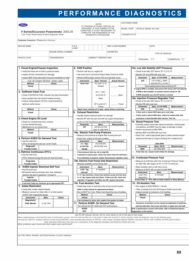
P E R F O R M A N C E D I A G N O S T I C S
89
CUSTOMER NAME
F-Series/Excursion Powerstroke 2003.25
MODEL YEAR VEHICLE SERIAL N0.(VIN)
6.0L Power Stroke Diesel Engine Diagnostic Guide CHASSIS STYLE
Customer Concerns (Please list in this box)
DEALER NAME 1863 CLAIM NUMBER DATE
ENGINE SERIAL NUMBER ODOMETERTYPE OF SERVICE
VEHICLE GVW TRANSMISSION AMBIENT TEMPERATUREPERSONAL COMMERCIAL
P & ACODE
-NOTE-IF CONCERN IS FOUND, SERVICE AS REQUIRED. IF THIS CORRECTS THE
CONDITION, IT IS NOT NECESSARY TO COMPLETE THE REMAINDER OF THE
DIAGNOSTIC PROCEDURE.
1. Visual Engine/Chassis Inspection 8. EGR Position 12a. Low Idle Stability (ICP Pressure)• Verify that there are no fluid or pressure leaks. • Perform with key on, engine off. • Check at low idle, EOT above 70° C (170° F)
• Inspect all wire connections for damage. • Use scan tool to command Output State Control for EGR. • Monitor ICP and RPM with scan tool.
• Inspect MAP hose,intercooler hose,and manifolds for leaks. • Monitor EGR position sensor PID and calculate travel.. Parameter Spec. @ 670 RPM Measurement
Fuel Oil Coolant Electrical Hoses Leaks Instrument Spec. Percent Actual Percent ICP 4.5-5.5 Mpa + .3MPa
Method Check Scan tool 0% (0.6-1.2 V) (650-800 PSI + 45 PSI)
Visual Closed _______ Closed Take reading before disconnecting ICP
If engine RPM is unstable, disconnect ICP sensor (ICP will default).
2. Sufficient Clean Fuel 90 % - 100% » If RPM is still unstable, re-connect sensor and go to 12b.
• Check if WATER IN FUEL indicator has been illuminated. (4.0-4.52 V) _______ Open » If RPM smoothes out, the ICP sensor is at fault.
• Drain sample from fuel control module housing. Open 12b. Injection Pressure Regulator Test• Cetane rating between 40-50 is recommended for • Check at low idle, EOT above 70° C (170° F)
optimum performance 90 % and 3.2 V _______ Travel • Monitor IPR with scan tool.Travel Parameter Spec. @ 670 RPM Measurement
Method Check » Repair issue causing out of spec. values before continuing. IPR 30 % MAX
Visual 9. Exhaust Restriction » If duty cycle is below MAX spec go to next step.
• Visually inspect exhaust system for damage » If duty cycle is above MAX spec, check for system leak with
3. Check Engine Oil Level • Monitor EP with the scan tool with the engine temperature procedure in Hard Start/No Start section. Test 10c.
• Check for contaminants (fuel, coolant). at 70° C (170° F)minimum at 3,800 RPM in park/neutral. 13. Boost Pressure Test• Correct Grade/Viscosity. Parameter Spec. Measurement • Carefully inspect intercooler tubes/connections, turbocharger• Miles/hours on oil, correct level. EP 234 kPa (34 PSI) connections, and MAP hose for signs of damage or leaks.
Method Check MAX '@ 3800 RPM • Perform boost test at 3300 RPM.
Visual 10a. Electric Fuel Pump Pressure • Monitor MGP and RPM with scan tool.
• Measure fuel pressure at engine filter housing test port. • Road Test - select appropriate gear to obtain desired engine
4. Perform KOEO On Demand Test • Road Test- engine at full load condition speed and full load on engine climbing hill or loaded truck..
• Use the scan tool. Instrument Spec. Measurement• DTCs set during this test are current faults. 0-1.1 Mpa 310-379 kPa 3300 RPM
Diagnostic (0-160 PSI) (45-55 PSI) min. Parameter Spec. PSI G MeasurementTrouble Codes Gauge MGP 22 PSIG MIN
5. Retrieve Continuous DTC's » If fuel pressure fails low, Go to step10b. » If test fails low, inspect turbo blades for damage.
• Use the scan tool. » If pressure is above spec, check fuel return lines for restriction.
• DTCs retrieved during this test are historical faults. If no restriction is present, replace fuel pressure regulator valve. 14. Crankcase Pressure Test Diagnostic 10b. Electric Fuel Pump Inlet Restriction • Measure at oil fill tube with 6.0L Crankcase Pressure Tester
Trouble Codes • Measure restriction at fuel pump inlet. p/n 303-758, with engine at 70° C (170° F) minimum.
6. KOEO Injector Electrical Self-Test Instrument Spec. Measurement • Block breather tube on left valve cover.
• Use the scan tool. 0-30 " Hg 6" Hg MAX • Measure at WOT with no load at 3,000 RPM.
• All injectors will momentarily click, then individual vacuum Instrument Spec. Measurementinjectors will click in sequence 1 though 8. » If > 6" Hg restriction, check lines between pump and fuel tank. (0-60" H²0) 8" H²0 MAX
Injector » If < 6" Hg, inspect both fuel filters. If filters are OK, check fuel Magnehelic
Trouble Codes regulator. If regulator and filters are OK, replace fuel pump. If more than 8 " H²0, refer to base engine in Shop Manual
» If self test codes are retrieved, go to appropriate PPT. 10c. Fuel Aeration Test 15. Oil Aeration Test 7. Intake Restriction • Install clear hose on fuel return line at fuel control module. • Run engine at 3000 RPM for 1 minute.
• Check filter minder switch/indicator. Refer to shop manual for approved procedure. • Take oil sample from the Oil Pressure Switch port at idle.
• Measure vacuum on clean side of air inlet system • Run at WOT for 2 min. Return fuel should be free of bubbles. • Inspect sample for presence of air bubbles.
at WOT with magnehelic gauge. Method Check Method Check
Instrument Spec. Check Visual VisualMagnehelic/ » If air is present in return fuel, inspect fuel system for leaks.
Filter Minder 2"-25" H²0 11. Perform KOER On Demand Test » Excessive oil aeration can be caused by depleated oil additives,
• This will test the ICP, EGR and VGT performance. pick-up tube leak, front cover seal leak, or upper pan seal leak.
KOER Note: If performance concern still exists, refer to Enhanced Injector
DTC Diagnostics in this section.
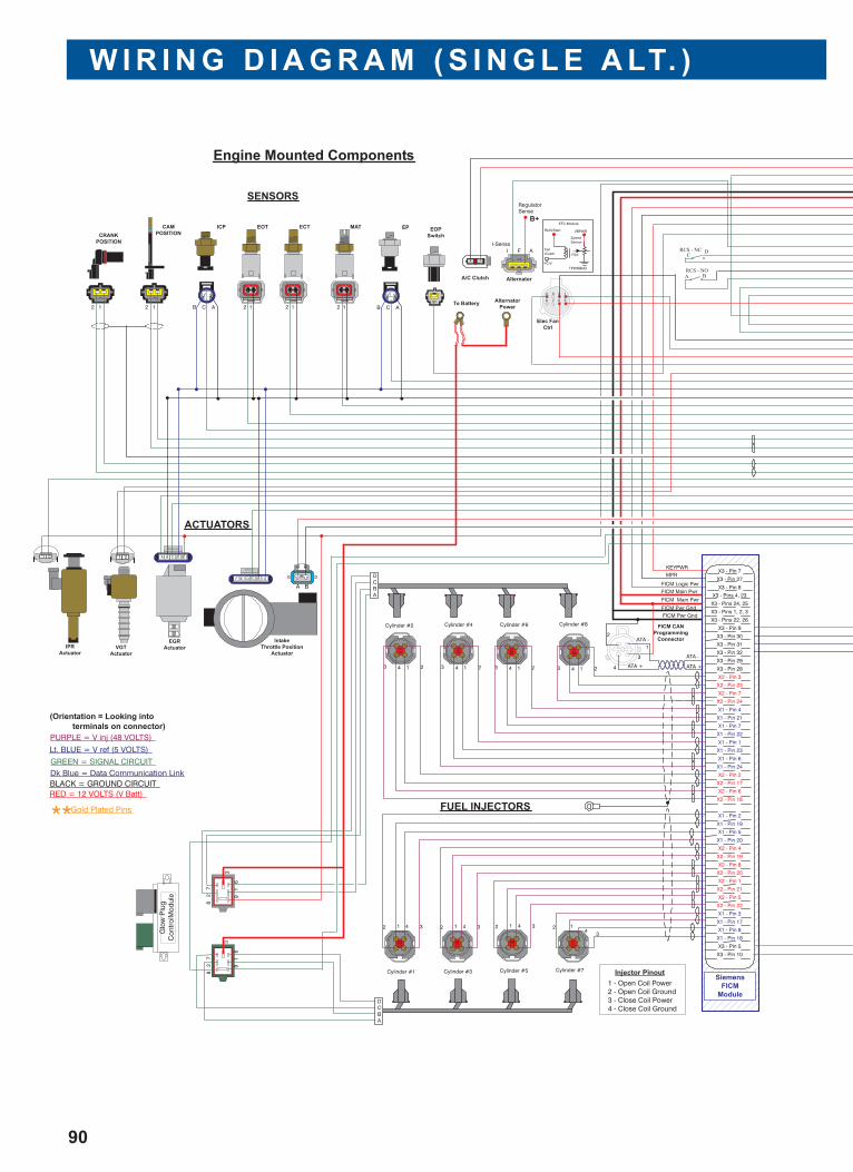
W I R I N G D I A G R A M ( S I N G L E A LT. )
90
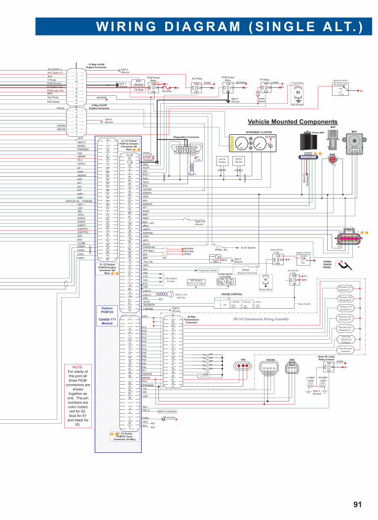
W I R I N G D I A G R A M ( S I N G L E A LT. )
91
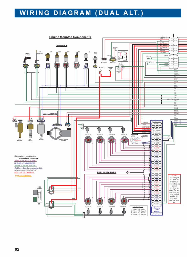
W I R I N G D I A G R A M ( D U A L A LT. )
92
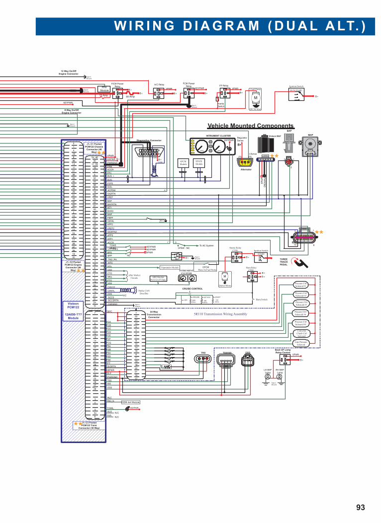
W I R I N G D I A G R A M ( D U A L A LT. )
93
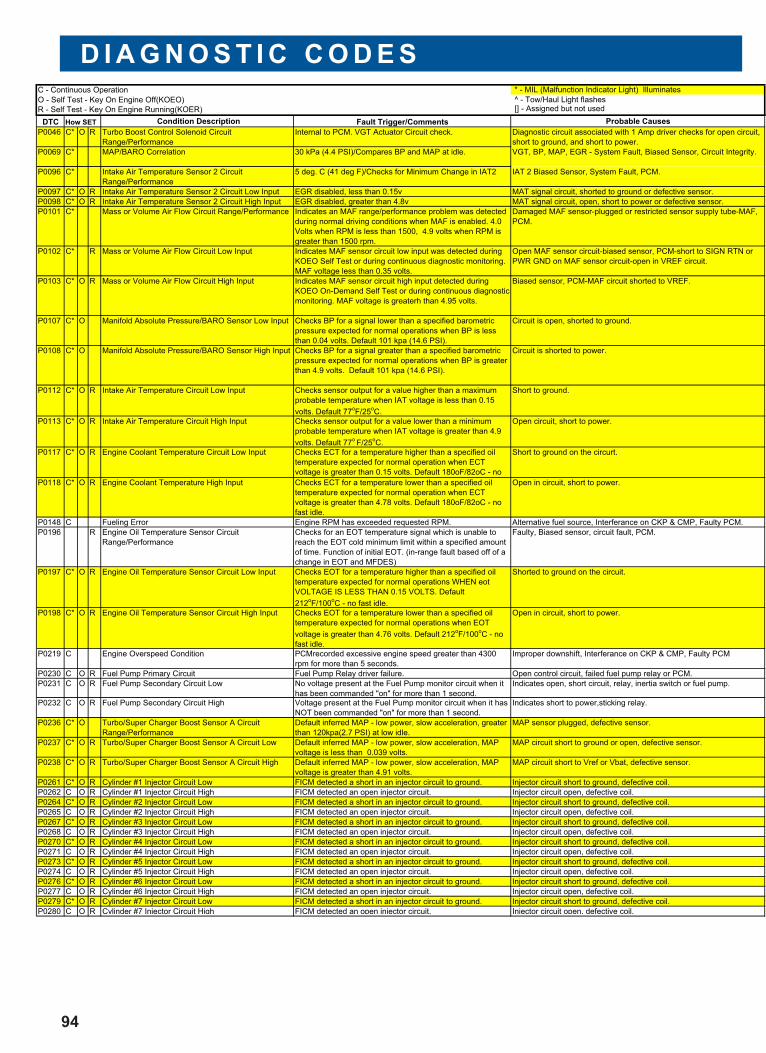
D I A G N O S T I C C O D E S
94
* - MIL (Malfunction Indicator Light) Illuminates
^ - Tow/Haul Light flashes [] - Assigned but not used
DTC Condition Description Fault Trigger/Comments Probable Causes
P0046 C* O R Turbo Boost Control Solenoid Circuit
Range/Performance
Internal to PCM. VGT Actuator Circuit check. Diagnostic circuit associated with 1 Amp driver checks for open circuit,
short to ground, and short to power.
P0069 C* MAP/BARO Correlation 30 kPa (4.4 PSI)/Compares BP and MAP at idle. VGT, BP, MAP, EGR - System Fault, Biased Sensor, Circuit Integrity.
P0096 C* Intake Air Temperature Sensor 2 Circuit
Range/Performance
5 deg. C (41 deg F)/Checks for Minimum Change in IAT2 IAT 2 Biased Sensor, System Fault, PCM.
P0097 C* O R Intake Air Temperature Sensor 2 Circuit Low Input EGR disabled, less than 0.15v MAT signal circuit, shorted to ground or defective sensor.
P0098 C* O R Intake Air Temperature Sensor 2 Circuit High Input EGR disabled, greater than 4.8v MAT signal circuit, open, short to power or defective sensor.
P0101 C* Mass or Volume Air Flow Circuit Range/Performance Indicates an MAF range/performance problem was detected
during normal driving conditions when MAF is enabled. 4.0
Volts when RPM is less than 1500, 4.9 volts when RPM is
greater than 1500 rpm.
Damaged MAF sensor-plugged or restricted sensor supply tube-MAF,
PCM.
P0102 C* R Mass or Volume Air Flow Circuit Low Input Indicates MAF sensor circuit low input was detected during
KOEO Self Test or during continuous diagnostic monitoring.
MAF voltage less than 0.35 volts.
Open MAF sensor circuit-biased sensor, PCM-short to SIGN RTN or
PWR GND on MAF sensor circuit-open in VREF circuit.
P0103 C* O R Mass or Volume Air Flow Circuit High Input Indicates MAF sensor circuit high input detected during
KOEO On-Demand Self Test or during continuous diagnostic
monitoring. MAF voltage is greaterh than 4.95 volts.
Biased sensor, PCM-MAF circuit shorted to VREF.
P0107 C* O Manifold Absolute Pressure/BARO Sensor Low Input Checks BP for a signal lower than a specified barometric
pressure expected for normal operations when BP is less
than 0.04 volts. Default 101 kpa (14.6 PSI).
Circuit is open, shorted to ground.
P0108 C* O Manifold Absolute Pressure/BARO Sensor High Input Checks BP for a signal greater than a specified barometric
pressure expected for normal operations when BP is greater
than 4.9 volts. Default 101 kpa (14.6 PSI).
Circuit is shorted to power.
P0112 C* O R Intake Air Temperature Circuit Low Input Checks sensor output for a value higher than a maximum
probable temperature when IAT voltage is less than 0.15
volts. Default 77oF/25
oC.
Short to ground.
P0113 C* O R Intake Air Temperature Circuit High Input Checks sensor output for a value lower than a minimum
probable temperature when IAT voltage is greater than 4.9
volts. Default 77oF/25
oC.
Open circuit, short to power.
P0117 C* O R Engine Coolant Temperature Circuit Low Input Checks ECT for a temperature higher than a specified oil
temperature expected for normal operation when ECT
voltage is greater than 0.15 volts. Default 180oF/82oC - no
Short to ground on the circurt.
P0118 C* O R Engine Coolant Temperature High Input Checks ECT for a temperature lower than a specified oil
temperature expected for normal operation when ECT
voltage is greater than 4.78 volts. Default 180oF/82oC - no
fast idle.
Open in circuit, short to power.
P0148 C Fueling Error Engine RPM has exceeded requested RPM. Alternative fuel source, Interferance on CKP & CMP, Faulty PCM.
P0196 R Engine Oil Temperature Sensor Circuit
Range/Performance
Checks for an EOT temperature signal which is unable to
reach the EOT cold minimum limit within a specified amount
of time. Function of initial EOT. (in-range fault based off of a
change in EOT and MFDES)
Faulty, Biased sensor, circuit fault, PCM.
P0197 C* O R Engine Oil Temperature Sensor Circuit Low Input Checks EOT for a temperature higher than a specified oil
temperature expected for normal operations WHEN eot
VOLTAGE IS LESS THAN 0.15 VOLTS. Default
212oF/100
oC - no fast idle.
Shorted to ground on the circuit.
P0198 C* O R Engine Oil Temperature Sensor Circuit High Input Checks EOT for a temperature lower than a specified oil
temperature expected for normal operations when EOT
voltage is greater than 4.76 volts. Default 212oF/100
oC - no
fast idle.
Open in circuit, short to power.
P0219 C Engine Overspeed Condition PCMrecorded excessive engine speed greater than 4300
rpm for more than 5 seconds.
Improper downshift, Interferance on CKP & CMP, Faulty PCM
P0230 C O R Fuel Pump Primary Circuit Fuel Pump Relay driver failure. Open control circuit, failed fuel pump relay or PCM.
P0231 C O R Fuel Pump Secondary Circuit Low No voltage present at the Fuel Pump monitor circuit when it
has been commanded "on" for more than 1 second.
Indicates open, short circuit, relay, inertia switch or fuel pump.
P0232 C O R Fuel Pump Secondary Circuit High Voltage present at the Fuel Pump monitor circuit when it has
NOT been commanded "on" for more than 1 second.
Indicates short to power,sticking relay.
P0236 C* O Turbo/Super Charger Boost Sensor A Circuit
Range/Performance
Default inferred MAP - low power, slow acceleration, greater
than 120kpa(2.7 PSI) at low idle.
MAP sensor plugged, defective sensor.
P0237 C* O R Turbo/Super Charger Boost Sensor A Circuit Low Default inferred MAP - low power, slow acceleration, MAP
voltage is less than 0.039 volts.
MAP circuit short to ground or open, defective sensor.
P0238 C* O R Turbo/Super Charger Boost Sensor A Circuit High Default inferred MAP - low power, slow acceleration, MAP
voltage is greater than 4.91 volts.
MAP circuit short to Vref or Vbat, defective sensor.
P0261 C* O R Cylinder #1 Injector Circuit Low FICM detected a short in an injector circuit to ground. Injector circuit short to ground, defective coil.
P0262 C O R Cylinder #1 Injector Circuit High FICM detected an open injector circuit. Injector circuit open, defective coil.
P0264 C* O R Cylinder #2 Injector Circuit Low FICM detected a short in an injector circuit to ground. Injector circuit short to ground, defective coil.
P0265 C O R Cylinder #2 Injector Circuit High FICM detected an open injector circuit. Injector circuit open, defective coil.
P0267 C* O R Cylinder #3 Injector Circuit Low FICM detected a short in an injector circuit to ground. Injector circuit short to ground, defective coil.
P0268 C O R Cylinder #3 Injector Circuit High FICM detected an open injector circuit. Injector circuit open, defective coil.
P0270 C* O R Cylinder #4 Injector Circuit Low FICM detected a short in an injector circuit to ground. Injector circuit short to ground, defective coil.
P0271 C O R Cylinder #4 Injector Circuit High FICM detected an open injector circuit. Injector circuit open, defective coil.
P0273 C* O R Cylinder #5 Injector Circuit Low FICM detected a short in an injector circuit to ground. Injector circuit short to ground, defective coil.
P0274 C O R Cylinder #5 Injector Circuit High FICM detected an open injector circuit. Injector circuit open, defective coil.
P0276 C* O R Cylinder #6 Injector Circuit Low FICM detected a short in an injector circuit to ground. Injector circuit short to ground, defective coil.
P0277 C O R Cylinder #6 Injector Circuit High FICM detected an open injector circuit. Injector circuit open, defective coil.
P0279 C* O R Cylinder #7 Injector Circuit Low FICM detected a short in an injector circuit to ground. Injector circuit short to ground, defective coil.
P0280 C O R Cylinder #7 Injector Circuit High FICM detected an open injector circuit. Injector circuit open, defective coil.
C - Continuous Operation
O - Self Test - Key On Engine Off(KOEO)
R - Self Test - Key On Engine Running(KOER)
How SET
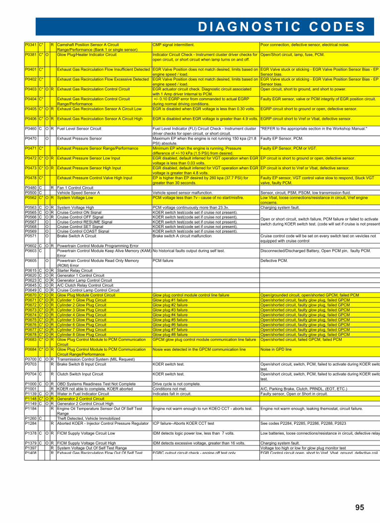
D I A G N O S T I C C O D E S
95
P0341 C* R Camshaft Position Sensor A Circuit
Range/Performance (Bank 1 or single sensor)
CMP signal intermittent. Poor connection, defective sensor, electrical noise.
P0381 C* O Glow Plug/Heater Indicator Circuit Indicator Circuit Check - Instrument cluster driver checks for
open circuit, or short circuit when lamp turns on and off.
Open/Short circuit, lamp, fuse, PCM.
P0401 C* Exhaust Gas Recirculation Flow Insufficient Detected EGR Valve Position does not match desired, limits based on
engine speed / load.
EGR Valve stuck or sticking - EGR Valve Position Sensor Bias - EP
Sensor bias.
P0402 C* Exhaust Gas Recirculation Flow Excessive Detected EGR Valve Position does not match desired, limits based on
engine speed / load.
EGR Valve stuck or sticking - EGR Valve Position Sensor Bias - EP
Sensor bias.
P0403 C* O R Exhaust Gas Recirculation Control Circuit EGR actuator circuit check. Diagnostic circuit associated
with 1 Amp driver Internal to PCM.
Open circuit, short to ground, and short to power.
P0404 C* Exhaust Gas Recirculation Control Circuit
Range/Performance
+/- 0.10 EGRP error from commanded to actual EGRP
during normal driving conditions.
Faulty EGR sensor, valve or PCM integrity of EGR position circuit.
P0405 C* O R Exhaust Gas Recirculation Sensor A Circuit Low EGR is disabled when EGR voltage is less than 0.30 volts. EGRP circuit short to ground or open, defective sensor.
P0406 C* O R Exhaust Gas Recirculation Sensor A Circuit High EGR is disabled when EGR voltage is greater than 4.9 volts. EGRP circuit short to Vref or Vbat, defective sensor.
P0460 C O R Fuel Level Sensor Circuit Fuel Level Indicator (FLI) Circuit Check - Instrument cluster
driver checks for open circuit, or short circuit.
"REFER to the appropriate section in the Workshop Manual."
P0470 O Exhaust Pressure Sensor Maximum EP when the engine is not running 150 kpa (21.8
PSI) absolute.
Faulty EP Sensor, PCM.
P0471 C* Exhaust Pressure Sensor Range/Performance Minimum EP when the engine is running, Pressure
difference of +/-10 kPa (1.5 PSI) from desired.
Faulty EP Sensor, PCM or VGT.
P0472 C* O R Exhaust Pressure Sensor Low Input EGR disabled, default inferred for VGT operation when EGR
voltage is less than 0.03 volts.
EP circuit is short to ground or open, defective sensor.
P0473 C* O R Exhaust Pressure Sensor High Input EGR disabled, default inferred for VGT operation when EGR
voltage is greater than 4.8 volts.
EP circuit is short to Vref or Vbat, defective sensor.
P0478 C* Exhaust Pressure Control Valve High Input EP is higher than EP desired by 260 kpa (37.7 PSI) for
greater than 30 seconds.
Faulty EP sensor, VGT control valve slow to respond, Stuck VGT
valve, faulty PCM.
P0480 C R Fan 1 Control Circuit
P0500 C Vehicle Speed Sensor A Vehicle speed sensor malfunction. Sensor, circuit, PSM, PSOM, low transmission fluid.
P0562 C* O R System Voltage Low PCM voltage less than 7v - cause of no start/misfire. Low Vbat, loose connections/resistance in circuit, Vref engine
concerns.
P0563 C O R System Voltage High PCM voltage continuously more than 23.3v. Charging system fault.
P0565 C O R Cruise Control ON Signal KOER switch test(code set if cruise not present).
P0566 C O R Cruise Control OFF Signal KOER switch test(code set if cruise not present).
P0567 O Cruise Control RESUME Signal KOER switch test(code set if cruise not present).
P0568 O Cruise Control SET Signal KOER switch test(code set if cruise not present).
P0569 O Cruise Control COAST Signal KOER switch test(code set if cruise not present).
P0571 O Brake Switch A Circuit Brake switch A circuit malfunction Cruise control code will be set on every switch test on vevicles not
equipped with cruise control
P0602 C O R Powertrain Control Module Programming Error
P0603 C Powertrain Control Module Keep Alive Memory (KAM)
Error
No historical faults output during self test. Disconnected/Discharged Battery, Open PCM pin, faulty PCM.
P0605 O Powertrain Control Module Read Only Memory
(ROM) Error
PCM failure Defective PCM.
P0615 C O R Starter Relay Circuit
P0620 C O R Generator 1 Control Circuit
P0623 C O R Generator Lamp Control Circuit
P0645 C O R A/C Clutch Relay Control Circuit
P0649 C O R Cruise Control Lamp Control Circuit
P0670 C* O R Glow Plug Module Control Circuit Glow plug control module control line failure Open/grounded circuit, open/shorted GPCM, failed PCM
P0671 C* O R Cylinder 1 Glow Plug Circuit Glow plug #1 failure Open/shorted circuit, faulty glow plug, failed GPCM
P0672 C* O R Cylinder 2 Glow Plug Circuit Glow plug #2 failure Open/shorted circuit, faulty glow plug, failed GPCM
P0673 C* O R Cylinder 3 Glow Plug Circuit Glow plug #3 failure Open/shorted circuit, faulty glow plug, failed GPCM
P0674 C* O R Cylinder 4 Glow Plug Circuit Glow plug #4 failure Open/shorted circuit, faulty glow plug, failed GPCM
P0675 C* O R Cylinder 5 Glow Plug Circuit Glow plug #5 failure Open/shorted circuit, faulty glow plug, failed GPCM
P0676 C* O R Cylinder 6 Glow Plug Circuit Glow plug #6 failure Open/shorted circuit, faulty glow plug, failed GPCM
P0677 C* O R Cylinder 7 Glow Plug Circuit Glow plug #7 failure Open/shorted circuit, faulty glow plug, failed GPCM
P0678 C* O R Cylinder 8 Glow Plug Circuit Glow plug #8 failure Open/shorted circuit, faulty glow plug, failed GPCM
P0683 C* O R Glow Plug Control Module to PCM Communication
Circuit
GPCM glow plug control module communication line failure Open/shorted circuit, failed GPCM, failed PCM
P0684 C* O R Glow Plug Control Module to PCM Communication
Circuit Range/Performance
Nosie was detected in the GPCM communication line Noise in GPD line
P0700 C O R Transmission Control System (MIL Request)
P0703 R Brake Switch B Input Circuit KOER switch test. Open/short circuit, switch, PCM, failed to activate during KOER switc
test.
P0704 C R Clutch Switch Input Circuit KOER switch test. Open/short circuit, switch, PCM, failed to activate during KOER switc
test.
P1000 C O R OBD Systems Readiness Test Not Complete Drive cycle is not complete.
P1001 R KOER not able to complete, KOER aborted Conditions not met. A/C, Parking Brake, Clutch, PRNDL, (EOT, ETC.)
P1139 C O R Water in Fuel Indicator Circuit Indicates falt in circuit. Faulty sensor, Open or Short in circuit.
P1148 C* O R Generator 2 Control Circuit
P1149 C O R Generator 2 Control Circuit High
P1184 R Engine Oil Temperature Sensor Out Of Self Test
Range
Engine not warm enough to run KOEO CCT - aborts test. Engine not warm enough, leaking themostat, circuit failure.
P1260 C Theft Detected, Vehicle Immobilized
P1284 R Aborted KOER - Injector Control Pressure Regulator ICP failure--Aborts KOER CCT test See codes P2284, P2285, P2286, P2288, P2623
P1378 C O R FICM Supply Voltage Circuit Low IDM detects logic power low, less than 7 volts. Low batteries, loose connections/resistance in circuit, defective relay
P1379 C O R FICM Supply Voltage Circuit High IDM detects excessive voltage, greater than 16 volts. Charging system fault.
P1397 R System Voltage Out Of Self Test Range Voltage too high or low for glow plug monitor test
P1408 R Exhaust Gas Recirculation Flow Out Of Self Test EGRC output circuit check - engine off test only EGR Control circuit open, short to Vref, Vbat, ground, defective coil.
Open or short circuit, switch failure, PCM failure or failed to activate
switch during KOER switch test. (code will set if cruise is not present
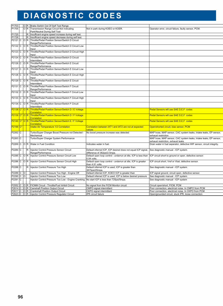
D I A G N O S T I C C O D E S
96
P1703 O R Brake Switch Out Of Self Test Range
P1705 O R Transmission Range Circuit Not Indicating
Park/Neutral During Self Test
Not in park during KOEO or KOER. Operator error, circuit failure, faulty sensor, PCM.
P1725 R Insufficent engine speed increase during self test.
P1726 R Insufficent engine speed decrease during self test.
P2121 C O R Throttle/Pedal Position Sensor/Switch D Circuit
Range/Performance
P2122 C O R Throttle/Pedal Position Sensor/Switch D Circuit Low
Input
P2123 C O R Throttle/Pedal Position Sensor/Switch D Circuit High
Input
P2124 C O R Throttle/Pedal Position Sensor/Switch D Circuit
Intermittent
P2126 C O R Throttle/Pedal Position Sensor/Switch E Circuit
Range/Performance
P2127 C O R Throttle/Pedal Position Sensor/Switch E Circuit Low
Input
P2128 C O R Throttle/Pedal Position Sensor/Switch E Circuit High
Input
P2129 C O R Throttle/Pedal Position Sensor/Switch E Circuit
Intermittent
P2131 C O R Throttle/Pedal Position Sensor/Switch F Circuit
Range/Performance
P2132 C O R Throttle/Pedal Position Sensor/Switch F Circuit Low
Input
P2133 C O R Throttle/Pedal Position Sensor/Switch F Circuit High
Input
P2134 C O R Throttle/Pedal Position Sensor/Switch F Circuit
Intermittent
P2138 C* O R Throttle/Pedal Position Sensor/Switch D / E Voltage
Correlation
Pedal Sensors will use SAE D,E,F codes
P2139 C* O R Throttle/Pedal Position Sensor/Switch D / F Voltage
Correlation
Pedal Sensors will use SAE D,E,F codes
P2140 C* O R Throttle/Pedal Position Sensor/Switch E / F Voltage
Correlation
Pedal Sensors will use SAE D,E,F codes
P2199 C* Intake Air Temperature 1/2 Correlation Correlation between IAT1 and IAT2 are not at expected
values
Open/shorted circuit, bias sensor, PCM
P2262 C Turbo/Super Charger Boost Pressure not Detected -
Mechanical
No boost pressure increase was detected MAP hose, MAP sensor, CAC system leaks, Intake leaks, EP sensor,
exhaust restriction
P2263 C Turbo/Super Charger System Performance MAP hose, MAP sensor, CAC system leaks, Intake leaks, EP sensor,
exhaust restriction, exhaust leaks
P2269 C O R Water in Fuel Condition Indicates water in fuel. Drain water in fuel seperator, defective WIF sensor, circuit integrity.
P2284 C R Injector Control Pressure Sensor Circuit
Range/Performance
Default inferred ICP, ICP desired does not equal ICP signal,
difference of 362psi/2.5mpa.
See diagnostic manual - ICP system.
P2285 C O R Injector Control Pressure Sensor Circuit Low Default open loop control - underrun at idle, ICP is less than
0.04 volts.
ICP circuit short to ground or open, defective sensor.
P2286 C O R Injector Control Pressure Sensor Circuit High Default open loop control - underrun at idle, ICP is greater
than 4.91 volts.
ICP circuit short, Vref or Vbat, defective sensor.
P2288 C R Injector Control Pressure Too High Default inferred ICP is used, ICP is greater than
3675psi/25mpa.
See diagnostic manual - ICP system.
P2289 C O Injector Control Pressure Too High - Engine Off Default inferred ICP, KOEO ICP is greater than ICP signal ground, circuit open, defective sensor.
P2290 C O Injector Control Pressure Too Low Default inferred ICP is used, ICP is below desired pressure See diagnostic manual - ICP system.
P2291 C Injector Control Pressure Too Low - Engine Cranking No start ICP is less than 725psi/5mpa. See diagnostic manual - ICP system
P2552 C O R FICMM Circuit - Throttle/Fuel Inhibit Circuit No signal from the FICM Monitor circuit Circuit open/short, FICM, PCM
P2614 C O R Camshaft Position Output Circuit CMPO signal intermittent Poor connection, electrical noise. In CMPO from PCM
P2617 C O R Crankshaft Position Output Circuit CKPO signal intermittent Poor connection, electrical noise. In CKPO from PCM
P2623 C O R Injector Control Pressure Regulator Circuit IPR circuit failure Open/grounded circuit, stuck IPR, loose connection
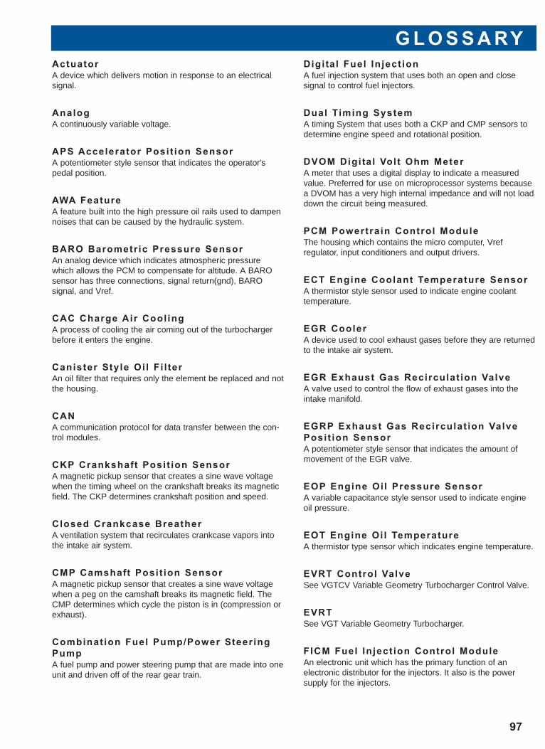
G L O S S A RY
97
ActuatorA device which delivers motion in response to an electricalsignal.
AnalogA continuously variable voltage.
APS Accelerator Posit ion SensorA potentiometer style sensor that indicates the operator'spedal position.
AWA FeatureA feature built into the high pressure oil rails used to dampennoises that can be caused by the hydraulic system.
BARO Barometr ic Pressure SensorAn analog device which indicates atmospheric pressurewhich allows the PCM to compensate for altitude. A BAROsensor has three connections, signal return(gnd), BARO signal, and Vref.
CAC Charge Air Cool ingA process of cooling the air coming out of the turbochargerbefore it enters the engine.
Canister Style Oi l F i l terAn oil filter that requires only the element be replaced and notthe housing.
CANA communication protocol for data transfer between the con-trol modules.
CKP Crankshaft Posit ion SensorA magnetic pickup sensor that creates a sine wave voltagewhen the timing wheel on the crankshaft breaks its magneticfield. The CKP determines crankshaft position and speed.
Closed Crankcase BreatherA ventilation system that recirculates crankcase vapors intothe intake air system.
CMP Camshaft Posit ion SensorA magnetic pickup sensor that creates a sine wave voltagewhen a peg on the camshaft breaks its magnetic field. TheCMP determines which cycle the piston is in (compression orexhaust).
Combinat ion Fuel Pump/Power Steer ingPumpA fuel pump and power steering pump that are made into oneunit and driven off of the rear gear train.
Digital Fuel In ject ionA fuel injection system that uses both an open and close signal to control fuel injectors.
Dual Timing SystemA timing System that uses both a CKP and CMP sensors todetermine engine speed and rotational position.
DVOM Digi ta l Volt Ohm MeterA meter that uses a digital display to indicate a measuredvalue. Preferred for use on microprocessor systems becausea DVOM has a very high internal impedance and will not loaddown the circuit being measured.
PCM Powertrain Control ModuleThe housing which contains the micro computer, Vref regulator, input conditioners and output drivers.
ECT Engine Coolant Temperature SensorA thermistor style sensor used to indicate engine coolanttemperature.
EGR CoolerA device used to cool exhaust gases before they are returnedto the intake air system.
EGR Exhaust Gas Recirculat ion ValveA valve used to control the flow of exhaust gases into theintake manifold.
EGRP Exhaust Gas Recirculat ion ValvePosit ion SensorA potentiometer style sensor that indicates the amount ofmovement of the EGR valve.
EOP Engine Oi l Pressure SensorA variable capacitance style sensor used to indicate engineoil pressure.
EOT Engine Oi l TemperatureA thermistor type sensor which indicates engine temperature.
EVRT Control ValveSee VGTCV Variable Geometry Turbocharger Control Valve.
EVRTSee VGT Variable Geometry Turbocharger.
FICM Fuel In ject ion Control ModuleAn electronic unit which has the primary function of an electronic distributor for the injectors. It also is the power supply for the injectors.
Glow Plug SleevesStainless steel sleeves used to protect the glow plugs fromcoolant.
GPCM Glow Plug Control ModuleModule which supplies power to the glow plugs and identifiesvariation in current flow to the glow plugs.
IAT Intake Air Temperature SensorA thermistor style sensor used to indicate air temperaturebefore the charge air cooler.
ICP Inject ion Control PressureA variable capacitance style sensor used to indicate highpressure oil system pressure.
IAT2 Intake Air Temperature 2 SensorA thermistor style sensor used to indicate air temperatureafter passing through the charge air cooler.
IDM Injector Driver ModuleAn electronic unit which has the primary function of an electronic distributor for the injectors. It also is the power supply for the injectors.
ImpedanceA form of opposition to AC current flow measured in Ohms.
I /O Injector TestA test that can be performed using the WDS to disable oneinjector at a time while watching Mfdes to determine a weakcontributing injector.
IPR Inject ion Pressure RegulatorControls injection oil pressure. An electrical signal to a solenoid creates a magnetic field which applies a variableforce on a poppet to control pressure. The quantity of fueldelivered to the combustion chamber is proportional to injec-tion control pressure.
IVS Idle Val idat ion SwitchAn on/off switch that indicates when the accelerator pedal isin the idle position.
KOEO Key on Engine Off TestA self-test operation that is performed with the ignition switchin the ON position with the engine OFF.
KOER Key on Engine Running TestA self-test operation that is performed with the ignition switchin the ON position and the engine RUNNING.
Long Li fe Ethylene Glycol CoolantA premium coolant, with an Ethylene Glycol base, that can beused in a cooling system for an extended time without need-ing to be changed. Long life coolants do not require the useof extenders. Long life coolants can be identified by its yellowcolor.
Main Power Relays(Two) Battery power relay switches for the ECM and IDM(modules) that are key power initiated and controlled by thecorresponding powered module.
MAP Manifold Absolute PressureA MAP sensor generates a digital frequency that indicatesmanifold boost pressure above atmospheric pressure. Thesignal is created by switching action caused by manifoldpressure of a diaphragm connected to a capacitor circuit inthe sensor. The digital frequency increases as pressureincreases. A MAP sensor has three connection: signalreturn(gnd), MAP signal, and Vref.
Misf ire Detect ionUses engine RPM changes during a firing cycle to determinea low contributing cylinder.
Modular Water PumpIs a water pump that uses the front cover as a housing andonly the hub and impeller are replaceable.
Normal ly ClosedRefers to a switch or a solenoid that is closed when no con-trol or force is acting on it.
Normal ly OpenRefers to a switch or a solenoid that is open when no controlor force is acting on it.
POT Potent iometerConverts a mechanical motion to a voltage value. Most oftenused to sense the position of a component. This sensorworks as a variable voltage divider. The wiper arm ismechanically connected to the component desired to besensed. Potentiometers have three connections: Vref, signalout, and ground.
Pulse WidthThe length of time an actuator, such as an injector, remainsenergized.
Relat ive Compression TestA test that can be run with the WDS to measure compressionof a cylinder relative to the other cylinders in the engine. Thistest is accomplished by comparing the rpm of the engine during each compression stroke.
G L O S S A RY
98
G L O S S A RY
99
Rocker Arm Carr ierA housing that the rocker arms and their fulcrums are mounted to.
ThermistorSensor used to determine temperature. A thermistor changesit's resistance value in relation to temperature change.Increasing temperature results in decreasing resistance,decreasing temperature results in increasing resistance. Thethermistor in conjunction with a current limiting resistor in thePCM forms a voltage divider that provides a voltage signalindicating temperature. Since the top half of the voltagedivider is the current limiting resistor and is internal to thePCM, a thermistor sensor only has two connections, signalreturn and ground.
Variable Capacitance SensorA sensor that is used to determine pressure. A variablecapacitance sensor changes it capacitance value in relationpressure change. Increasing pressure results in a lowercapacitance, thus increasing return voltage. Decreasing pressure results in a higher capacitance and a lower voltage.Variable capacitance sensors are 3 wire sensors.
VBATBattery voltage.
VGT Variable Geometry TurbochargerCould also be called EVRT. A turbocharger that has a turbinehousing that can change sizes through electronically con-trolled hydraulics.
VGTCV Variable Geometry TurbochargerControl ValveCould also be called EVRTCV. Controls oil flow in and out ofthe VGT actuator in order to change the effective size of itsturbine housing.
VPWRBattery voltage.
VSS Vehicle Speed SensorNormally a magnetic pickup style sensor that is mounted onthe tailshaft of the transmission to indicate ground speed.
I N D E X
100
DDual mass flywheel, 15
EECT (Engine Coolant Temperature), 54
EGRCooler, 37
Installation, 74Removal, 74
Flow, 37Throttle, 38Valve, 37-38
Removal, 73VP (Valve Position), 55
Electrical Components, 49,65
Emission label, 8
Engine mounted fuel filter, 30
Engine serial number, 8
EOP (Engine Oil Pressure, 56
EOT (Engine Oil Temperature, 57
EP (Exhaust Pressure), 58
FFeatures, 6
FICM (Fuel Injection Control Module), 65
Forward, 1
Front cover, 24Dowel locations, 76Installation, 77Removal, 76
Fuel filter replacement, 69
Fuel injector, 43Coil, 47End of main injection, 47Features, 43Fill cycle, 45Main injection, 46O-rings, 43Spool valve, 43
AActuators, 64
Air filter/ filter minder, 33
Air in fuel, 79
Air management systemfeatures, 31flow, 31-32
AP (Accelerator Pedal), 50
BBP (Barometric Pressure), 51
Barrel, 44
bed plate, 22
Bridges, 72
CCharge air cooler, 33
CKP (Crankshaft Position), 52
CMP (Camshaft Position), 53
Component Locations, 9-13
Coolant recovery bottle, 20
Cooling systemFeatures, 17Flow, 17-19
Crankcase pressure test, 82
Crankcase ventilation, 74
CrankshaftHeat treatment discoloration, 15Primary flange, 78Rear seal dust cover, 78
Cylinder balance test, 81
Cylinder head, 14Removal,72
I N D E X
101
Fuel inlet check valves, 30
Fuel pressure regulator, 30
Fuel supply systemFeatures, 27Flow, 27-28
GGeneration II fuel management system
advantages, 39diagram, 39major components, 39
Glow plug, 67buss bar, 67
Removal, 77removal, 77sleeve, 20, 67
Removal, 73System, 66
Diagnostics, 68CM (Control Module), 66
HHFCM (Horizontal Fuel Conditioning Module), 29
High boost, 79
High EP, 79
High pressure oil rail, 42
High pressure oil system flow, 40-41
High pressure pump, 42cover, 42
removal, 76
Horsepower & Torque, 6
IIAT1 (Intake Air Temperature 1), 59
IAT2 (Intake Air Temperature 2), 60
ICP (Injection Control Pressure), 42, 61low, 80
Injection nozzle, 44
InjectorBuzz, 82I/O test, 80Installation, 71O-ring replacement, 70-71Removal, 69-70Sleeve, 19
Installation, 73Removal, 73
Intake manifold, 38, 75
Intensifier Piston, 44
IPR (Injection Pressure Regulator), 42,64Valve removal, 75
LLubrication system
Features, 21flow, 21-22
MMAF (Mass Air Flow), 62
MAP (Manifold Absolute Pressure), 63
OOil
aeration, 23Test, 81
Carryover, 74cooler, 24
housing, 24Filter, 25
Base, 24-25Replacement, 69
Pan, 22Pressure Regulator, 23pump, 23
Removal, 77Reservoir, 25-26
Screen, 25
Overview, 6
PPCM (Powertrain Control Module), 66
Pick-up tube, 23
Plunger, 44
Power or ground issues, 80
I N D E X
102
RRear Geartrain, 14
Relative compression test, 81
Rocker Arms, 72
Rocker carrier, 14Removal, 72
Rocker fulcrums, 72
SSensors overview, 49
Single mass flywheel, 15
Specifications, 7
Stages of injection, 45
TTable of contents, 3
TurbochargerOil drain tube, 26
Removal, 75Oil supply, 26
Removal, 74
VVGT (Variable Geometry Turbocharger)
Compressor, 34Control valve, 35
Flow, 35Features, 34Turbine, 34Vanes closed, 36Vanes open, 34Vanes partially closed, 36
VGTCV (Variable Geometry Turbocharger Control Valve), 65
W
Water pump, 19

N O T E S
103
N O T E S
104