60297-3 - textron lycoming operators manual -...
TRANSCRIPT

OPERATOR'S
MANUAL
AVCO LYCOMING
0-340 SERIES
AIRCRAFT ENGINES
Approve
Part No.
d by F.A.A. June
2nd Edition
60297-3 Price
1975
$5.00
AVCO LYCOMING DIVISIONWILLIAMSPORT, PENNSYLVANIA
Printed in U.S.A.

AVCO LYCOMING OPERATOR'S MANUAL
ATTENTION
OWNERS, OPERATORS, ANDMAINTENANCE PERSONNEL
This operator's manual contains a description of the engine, itsspecifications, and detailed information on how to operate and maintainit. Such maintenance procedures that may be required in conjunction withperiodic inspections are also included. This manual is intended for use byowners, pilots and maintenance personnel responsible for care of AvcoLycoming powered aircraft. Modifications and repair procedures arecontained in Avco Lycoming overhaul manuals; maintenance personnelshould refer to these for such procedures.
SAFETY WARNING
Neglecting to follow the operating instructions and to carry outperiodic maintenance procedures can result in poor engine performanceand power loss. Also, if power and speed limitations specified in thismanual are exceeded, for any reason; damage to the engine and personalinjury can happen. Consult your local FAA approved maintenance facility.
SERVICE BULLETINS, INSTRUCTIONS, AND LETTERS
Although the information contained in this manual is up-to-date at timeof publication, users are urged to keep abreast of later informationthrough Avco Lycoming Service Bulletins, Instructions and Service Letterswhich are available from all Avco Lycoming distributors or from thefactory by subscription. Consult the latest edition of Service Letter No.L114 for subscription information.
SPECIAL NOTE
The illustrations, pictures and drawings shown in this publication aretypical of the subject matter they portray; in no instance are they to beinterpreted as examples of any specific engine, equipment or part thereof.
TEXTRON LYCOMING OPERATOR'S MANUAL
IMPORTANT SAFETY NOTICE
Proper service and repair is essential to increase the safe, reliableoperation of all aircraft engines. The service procedures recommendedby Textron Lycoming are effective methods for performing serviceoperations. Some of these service operations require the use of toolsspecially designed for the task. These special tools must be used whenand as recommended.
It is important to note that most Textron Lycoming publications con-tain various Warnings and Cautions which must be carefully read inorder to minimize the risk of personal injury or the use of improper ser-vice methods that may damage the engine or render it unsafe.
It is also important to understand that these Warnings and Cautionsare not all inclusive. Textron Lycoming could not possibly know.evaluate or advise the service trade of all conceivable ways in which ser-vice might be done or of the possible hazardous consequences that maybe involved. Acordingly, anyone who uses a service procedure must firstsatisfy themselves thoroughly that neither their safety nor aircraft safe-ty will be jeopardized by the service procedure they select.

Lycoming
WAR RANTY(LIMITED)
NEW AND REMANUFACTUREDRECIPROCATING AIRCRAFT ENGINE
WHAT TEXTRON LYCOMING PROMISES YOU
Textron Lycoming warrants each new and remanufactured reciprocating engine sold by it to be free from defects in
material and workmanship appearing within one (1) year from the date of first operation, excluding necessary aircraftacceptance testing. The date of first operation must not exceed two (2) years from the date of shipment from TextronLycoming.
Textron Lycoming's obligation under this warranty shall be limited to its choice of repair or replacement, on an ex-change basis,ofthe engine oranypartof the ngine, whenTextron Lycoming has determined that theengineisdefectivein material or workmanship. Such repair or replacement will be made by Textron Lycoming at no charge to you. TextronLycoming will also bear the cost for labor in connection with the repair or replacement as provided in TextronLycoming's then current Removal and Installation Labor Allowance Guidebook.
In addition, if Textron Lycoming determines that the engine proves to be defective in material or workmanship duringthe period until the expiration of Textron Lycoming's recommended Time Between Overhaul (TBO), or two (2) yearsfrom the date of first operation, whichever occurs first, Textron Lycoming will reimburse you for a pro rata portion of thecharge for the repair or replacement (at its choice) with Textron Lycoming parts. of parts required to be repaired or re-placed, ora replacement engine, ifit determines that engine replacement is required. Textron Lycoming's obligationduring the proraton period extends to major parts of the engine, which are limited to crankcase, crankshaft, camshaft,cylinders, connecting rods, pistons, sump, ac:essory housing and gears. The proration policy does not extend to labor orto accessories, including but not limited to magnetos, carburetors or fuel injectors, fuel pumps, starters, alternators andturbochargers and their controllers.
Any engine or part so repaired or replaced will be entitled to warranty for the remainder of the original warranty period.
YOUR OBLIGATIONS
The engine must have received normal use and service. You must apply for warranty with an authorized TextronLycoming distrbutor within 30 days of the appearance of the defect in material or workmanship.
Textroll Lycoming's warranty does not cover normal maintenance expenses or consumable items. The obligations onthe part of Textron Lycoming set forth above are your exclusive remedy and the exclusive liability of Textron Lycoming.This warranty allocates die risk of product failure between you and Textron Lycoming, as permitted by applicable law.
Textron Lycoming reserves the right to deny any warranty claim if it reasonably determines that the engine or part has
been subject to accident or used, adjusted, altered, handled. maintained or stored other than as directed in your operator'smanual, or if non-genuine Textron Lycoming pans are installed in or on the engine and are determnined to be a possiblecause of the incident for which die warranty application is filed.
Textron Lycoming may change the construction of engines at any time without incurring any obligation to incorporatesuch alterations in engines or parts previousJy sold.

I
I
THIS LIMITED WARRANTY IS EXCLUSIVE AND IN LIEU OF ALL OTHER WARRANTIES AND REPRESEN-TATIONS, EXPRESS OR IMPLIED OR STATUTORY, WHETHER WRITTEN OR ORAL, INCLUDING BUT NOTLIMITED TO ANY WARRANTY OF MERCHANTABILITY OR FITNESS FOR ANY PARTICULAR PURPOSE,AND ANY IMPLIED WARRANTY ARISING FROM ANY COURSE OF PERFORMANCE OR DEALING ORTRADE USAGE. THIS WARRANTY IS ALSO IN LIEU OF ANY OTHER OBLIGATION, LIABILITY, RIGHT ORCLAIM, WHETHER IN CONTRACT OR IN TORT, INCLUDING ANY RIGHT IN STRICT LIABILITY INTORT OR ANY RIGHT ARISING FROM NEGLIGENCE ON THE PART OF TEXTRON LYCOMING, ANDTEXTRON LYCOMING'S LIABILITY ON SUCH CLAIM SHALL IN NO CASE EXCEED THE PRICE ALLO-CABLE TO THE ENGINE OR PART WHICH GIVES RISE TO THE CLAIM.
LIMITATION OF LIABILITY
IN NO EVENT, WHETHER AS A RESULT OF A BREACH OF WARRANTY, CONTRACT OR ALLEGED NEG-LIGENCE, SHALL TEXTRON LYCOMING BE LIABLE FOR SPECIAL OR CONSEQUENTIAL OR ANY OTHERDAMAGES, INCLUDING BUTNOT LIMITED TOLOSSOFPROFITSORREVENUES, LOSS OFUSE OFTHEENGINE OR COST OF A REPLACEMENT.
No agreement varying this warranty or Textron Lycoming's obligations under it will be binding upon TextronLycoming unless in writing signed by a duly authorized representative of Textron Lycoming.
Effective October 1, 1995 Revision "J"
Textron LycomingWilliamsport, Pennsylvania <

WARRANTY(LIMITED)
REPLACEMENT PART - RECIPROCATING AIRCRAFT ENGINE
WHAT TEXTRON LYCOMING PROMISES YOU
Textron Lycoming warrants each new reciprocating aircraft engine replacement part sold by it to be free from defectsinmaterial and workmanshipappearing within one (1) year from its date of first operation. The date of first opera-tion. must not exceed two (2) years from the date of shipment from Textron Lycoming.
Textron Lycoming's obligation under this warranty shall be limited to its choice of repair or replacement. on an ex-change basis, of the replacement part, when Textron Lycoming has determined that the part is defective in material orworkmanship. Textron Lycoming will also reimburse you for the costs for labor inconnection with the repair or replace-ment as provided in Textron Lycoming's then current Removal and Installation Labor Allowance Guidebook.
Any part so repaired or replaced will be warranted for the remainder of the original warranty period.
YOUR OBLIGATIONS
The engine in which the replacement part is installed must have received normal use and service. You must apply forwarranty with an authorized Textron Lycoming distributor within 30 days of the appearance of the defect in material orworkmananship.
Textron Lycoming's warranty does not cover normal maintenance expenses or consumable items. The obligations onthe part of Textron Lycoming set forth above are your exclusive remedy and the exclusive liability of Textron Lycoming.This warranty allocates the risk of product failure between you and Textron Lycoming, as pennitted by applicable law.
Textron Lycoming reserves the right to deny any warranty claim if it reasonably determines that the engine or part hasbeen subject to accident or used, adjusted, altered, handled, maintained or stored other than as directed in your operator'smanual, or if non-genuine Textron Lycoming pans are installed in or on the engine and are determined to be a possiblecause of the incident for which the warranty application is filed.
Textron Lycoming may change the construction of engines at any time without incurring any obligation to incorporatesuch alterations in engines or parts previously sold.
THIS LIMITED WARRANTY IS EXCLUSIVE AND IN LIEU OF ALL OTHER WARRANTIES AND REPRESEN-TATIONS EXPRESS OR IMPLIED OR STATUTORY. WHETHER WRITTEN OR ORAL, INCLUDING BUT NOTLIMITED TO ANY WARRANTY OFMERCHANTABILITY OR FITNESS FOR ANY PARTICULAR PURPOSE,AND ANY IMPLIED WARRANTY ARISING FROM ANY COURSE OF PERFORMANCE OR DEALING ORTRADE USAGE. THIS WARRANTY IS ALSO IN LIEU OFANY OTHER OBLIGATION, LIABILITY. RIGHT ORCLAIM, WHETHER IN CONTRACT OR IN TORT, INCLUDING ANY RIGHT IN STRICT LIABILITY INTORT OR ANY RIGHT ARISING FROM NEGLIGENCE ON THE PART OF TEXTRON LYCOMING, ANDTEXTRON LYCOMING'S LIABILITY ON SUCH CLAIM SHALL IN NO CASE EXCEED THE PRICE ALLO-CABLE TO THE ENGINE OR PART WHICH GIVES RISE TO THE CLAIM.
LIMITATION OF LIABILITY
IN NO EVENT, WHETHER AS A RESULT OF A BREACH OF WARRANTY, CONTRACT OR ALLEGED NEG-LIGENCE, SHALL TEXTRON LYCOMING BE LIABLE FOR SPECIAL OR CONSEQUENTIAL OR ANY OTHERDAMAGES, INCLUDING BUT NOT LIMITED TO LOSS OF PROFITS OR REVENUES, LOSS OF USE OFTHEENGINE OR COST OF A REPLACEMENT.
No agreement varying this warranty or Textron Lycoming's obligations under it will be binding upon TextronLycoming unless in writing signed by a duly authorized representative of Textron Lycoming.
Effective October 1, 1995 Revision "J"
Textron LycomingWilliamsport, Pennsylvania

Lycoming
WARRANTY(LIMITED)
OVERHAULEDRECIPFIOCATING AIRCRAFT ENGINE
WHAT TEXTRON LYCOMING PROMISES YOU
Textron Lycoming warrants each overhauled reciprocating engine sold by it to be free from defects in material and
workmanship appearing within one (1) year from the date of first operation, excluding necessary aircraft acceptance
testing. The date of first operation must not exceed two (2) years from the date of shipment from Textron Lycoming.
Textron Lycoming's obligation under this warranty shall be limited to its choice of repairorreplacement, on an ex-
change basis, of the engine or any pat of the engine, when Textron Lycoming has determined that the engine is defectivein material or workmanship. Such repair or n:placement will be made by Textron Lycoming at no charge to you. Textron
Lycoming will also bear the cost for labor in connection with the repair or replacement as provided in Textron
Lycoming's then current Removal and Installation Labor Allowance Guidebook.
Any engine or part so repaired or replaced will be entitled to warranty for the remainder of the original warranty period.
YOUR OBLIGATIONS
The engine must have received normal use and service You must apply for warranty with an authorized Textron
Lycoming distributor within 30 days of the appearance of the defect in material or workmanship.
Textron Lycoming's warranty does not over normal maintenance expenses or consumable items The obligations onthe part of Textron Lycoming set forth above are your exclusive remedy and the exclusive liability of Textron Lycoming.
This warranty allocates the risk of product fiilure between you and Textron Lycoming, as permitted by applicable law.
Textron Lycoming reserves the right to deny any warranty claim if it reasonably determines that the engine or part has
been subject to accident or used, adjusted, altered, handled, maintained or stored other than as directed n your operator'smanual, or if non-genuine Textron Lycoming parts are installed in or on the engine and are determined to be a possible
cause of the incident for which the warranty application is filed.
Textron Lycoming may change the construction of engines at any time without incurring any obligation to incorporatesuch alterations in engines or pans previously sold.
THIS LIMITED WARRANTY IS EXCLUSIVE AND IN LIEU OF ALL OTHER WARRANTIES AND REPRESEN-TATIONS, EXPRESS OR IMPLIED OR STATUTORY, WHETHER WRITTEN OR ORAL, INCLUDING BUT NOTLIMITED TO ANY WARRANTY OF MERCHANTABILITY OR FITNESS FOR ANY PARTICULAR PURPOSE. <
AND ANY IMPLIED WARRANTY ARISING FROM ANY COURSE OF PERFORMANCE OR DEALING OR
TRADE USAGE THIS WARRANTY IS ALSO IN LIEU OFANY OTHER OBLIGATION. LIABILITY, RIGHT ORCLAIM, WHETHER IN CONTRACT OR IN TORT, INCLUDING ANY RIGHT IN STRICT LIABILITY INTORT OR ANY RIGHT ARISING FROM NEGLIGENCE ON THE PART OF TEXTRON LYCOMING, AND
TEXTRON LYCOMING'S LIABILITY ON SUCH CLAIM SHALL IN NO CASE EXCEED THE PRICE ALLO-CABLE TO THE ENGINE OR PART WHICH GIVES RISE TO THE CLAIM.

I
LIMITATION OF LIABILITY
IN NO EVENT, WHETHER AS A RESULT OFA BREACH OFWARRANTY, CONTRACT OR ALLEGED NEG-LIGENCE, SHALL TEXTRON LYCOMING BE LIABLE FOR SPECIAL OR CONSEQUENTIAL OR ANY OTHERDAMAGES, INCLUDING BUT NOT LIMITED TO LOSS OF PROFITS OR REVENUES, LOSS OF USE OFTHEENGINE OR COST OF A REPLACEMENT.
No agreement varying this warranty or Textron Lycoming's obligations under it will be binding upon TextronLycoming unless in writing signed by a duly authorized representative of Textron Lycoming.
4
Effective October 1, 1995 Revision "J"
4Textron Lycoming
Williamsport, Pennsylvania4
4
4

AVCO LYCOMING OPERATOR'S MANUAL
TABLE OF CONTENTS
Page
SECTION 1 DESCRIPTION 1-1
SECTION 2 SPECIFICATIONS 2-1
SECTION 3 OPERATING INSTRUCTIONS 3-1
SECTION 4 PERIODIC INSPECTION 4-1
SECTION 5 MAINTENANCE PROCEDURES 5-1
SECTION 6 TROUBLE-SHOOTING 6-1
SECTION 7 INSTALLATION AND STORAGE 7-1
SECTION 8 TABLES 8-1


Rear View - O-340-A1A

AVCO LYCOMING OPERATOR'S MANUAL
DESCRIPTION
Page
General .......Cylinders .......Valve Operating Mechanism
Crankshaft ..... . . . . . . .
Crankcase ......Oil Sump .............Connecting Rods ........Pistons .......Accessory Housing .......Gears .......Cooling System ....Lubrication System .......Induction System ........Ignition System .........Generator and Starter .....Accessory Drives ........
. . . . . . . . . . . . . . . . .1-1
................ .1-1
................ .1-1
. . . . . . . . . . . . . . . . . 1-2
. . . . . . . . . . . . . . . . .1-2
. . . . . . . . . . . . . . . . . 1-2
. . . . . . . . . . . . . . . . .1-2
. . . . . . . . . . . . . . . . . 1-2
. . . . . . . . . . . . . . . . . 1-2
. . . . . . . . . . . . . . . . .1-2
. . . . . . . . . . . . . . . . .1-3
. . . . . . . . . . . . . . . . . 1-3
. . . . . . . . . . . . . . . . . 1-4.. . . . . . . . . . . . . . . 1-4
. . . . . . . . . . . . . . . . .1-4. . . . . . . . . . . . . . . . 1-4

AVCO LYCOMING OPERTOR'S MANUAL
0-340-A1A SECTION 1
SECTION 1
DESCRIPTION
General - The Avco Lycoming 0-340-A1A aircraft engine is a four cylinderwet sump, horizontally opposed model. The cylinders are not directlyopposite from each other but are staggered, thus permitting a separatethrow on the crankshaft for each connecting rod.
Cylinders - The cylinders are of conventional air cooled design with thetwo major parts, head and barrel, screwed and shrunk together. The headsare made from an aluminum alloy casting with a fully machinedcombustion chamber. The cylinder barrel, which is machined from achrome nickel molybdenum steel forging with deep integral cooling fins, isground and honed to a specified finish.
NOTE
Standard engines are furnished with unplated cylinder barrels and chromeplated piston rings. Engines rebuilt with chrome plated barrels requireunplated piston rings.
The valve rocker shaft bearing supports and the rocker box housing arecast integrally with the cylinder head. The valves are cooled by means offins which completely surround the area of the exhaust valve and portionsof the intake valve. A sodium-cooled rotator type exhaust valve isemployed on this engine. Bronze valve guides and austenitic chrome nickelsteel valve seats are shrunk into machined recesses in the head.
WARNING
Do not under any circumstances assemble chrome plated piston rings in achrome plated cylinder barrel. Chrome plated cylinders are identified bythe fin area between the spark plug hole and the cylinder barrel paintedorange. Consult Service Instruction No. 1181.
Valve Operating Mechanism - The valve operating mechanism is located onthe top side of the engine, facilitating proper lubrication and easyaccessibility. The camshaft is located parallel to and above the crankshaftand operates in aluminum bearings. The camshaft in turn actuates thevalves by means of mushroom type hydraulic tappets, which automaticallykeep the valve clearance at zero. The valve rockers are supported on a fullfloating steel pin. The valve springs bear against both upper and lower steelseats and are retained on the valve stems by means of split keys.
1-1

AVCO LYCOMING OPERATOR'S MANUAL
SECTION 1 0-340-A1A
Crankshaft - The crankshaft is made from a chrome nickel molybdenumsteel forging. All bearing journal surfaces are nitrided, and centrifugalsludge removers are provided in the form of oil tubes at each crankpinjournal. These tubes can easily be removed during overhaul of the engineand accumulated sludge cleaned out.
NOTE
Crankshafts on standard 0-340-A IA engines, which are equipped for fixedpitch operation, are not interchangeable with crankshafts furnished withO-320-A1A engines equipped to operate with constant speed propellergovernors.
Crankcase - The crankcase assembly consists of two reinforced aluminumalloy castings divided vertically at the center line of the engine andfastened together by means of through bolts and nuts. The mating surfacesof the crankcase are joined without the use of a gasket, and the mainbearing bores are machined for use of precision type main bearing inserts.
Oil Sump - The oil sump incorporates an oil screen filter, carburetormounting pad, the intake riser, and the intake pipe connections. The fuelair mixture, as it passes through the riser, is vaporized by the heated oil inthe sump that surrounds the riser.
Connecting Rods - The connecting rods are made in the form of "H"sections from alloy steel forgings. They have replaceable bearing inserts inthe crankshaft ends and split type bronze bushings in the piston ends. Thebearing caps on the crankshaft ends of the rods are retained by means oftwo bolts and nuts through each cap.
Pistons - The pistons are machined from aluminum alloy and their generalconstruction is of the full skirt type. Two compression rings and an oilregulator ring are located above the piston pin. The piston pin is of the fullfloating type with an aluminum plug located at each end to prevent thepin from touching the cylinder wall.
Accessory Housing - The accessory housing is made from an aluminumcasting and is fastened to the rear of the crankcase and the top rear of thesump. It forms a housing for the oil pump and the drives for thetachometer, magnetos, and other accessories.
Gears - The gears are of the conventional spur type and are precisionmachined. They are hardened to insure long life and satisfactory operatingqualities.
1-2

AVCO LYCOMING OPERATOR'S MANUAL
0-340-A1A SECTION 1Cooling System - The air pressure cooling system is actuated by theforward speed of the plane. Baffles are provided to build up a pressurebetween the cowling and the top of the cylinders, thus forcing the cool airdown through the cylinder fins. The air is then exhausted through gills oraugmentor tubes usually located at the rear of the engine cowling.Lubrication System - The lubrication system is of the pressure wet sumptype. The main bearings, connecting rod bearings, camshaft bearings, valvetappets, and push rods are lubricated by positive pressure. Piston pins,gears, cylinder walls, and other parts are lubricated by means of oilcollectors and spray. The oil pump, which is located in the accessoryhousing, draws oil through a tube from an oil suction screen located in thesump. The oil from the pump then enters a drilled passage in the accessoryhousing, which feeds the oil to a threaded connection on the rear face ofthe accessory housing, where a flexible line leads the oil to the external oilcooler. Pressure oil from the cooler returns to a second threadedconnection on the accessory housing, from which point a drilled passageconducts the oil to the oil pressure screen, which is contained in a castchamber mounted on the accessory housing. In the event that cold oil oran obstruction should restrict the flow of oil to the cooler, an oil coolerbypass valve is provided to pass the pressure oil directly from the oil pumpto the oil pressure screen chamber.
The oil pressure screen is provided as a means to filter from the oil anysolid particles that may have passed through the suction screen in thesump. After being filtered in the pressure screen chamber, the oil is fedthrough a drilled passage to the oil pressure relief valve, located in theupper right side of the crankcase in front of the accessory housing.
This relief valve regulates the engine oil pressure by allowing excessiveoil to return to the sump, while the balance of the pressure oil is fed to themain oil gallery in the right half of the crankcase. During its travel throughthis main gallery, the oil is distributed by means of separate drilledpassages to the main bearings of the crankshaft. The drilled passages to thebearings are located in such a manner as to form an inertia type filter.Thus, only the cleanest oil will be fed to the bearings. Separate passagesfrom the rear main bearing supply pressure oil to both crankshaft idlergears. Angular holes are drilled through the main bearings to the rodjournals where sludge removal tubes are located. Here the centrifugal forceof the crankshaft removes any sludge or heavy matter that may be presentin the oil. Oil from main oil gallery also flows to the cam and valve gearpassages, and is then conducted through branch passages to the hydraulictappets and camshaft bearings. Oil enters the tappets through indexingholes and travels out through the hollow push rods to the valvemechanism, lubricating the valve rocker bearings and valve stems. Residualoil from the bearings, accessory drives, and rocker boxes is returned bygravity to the sump, where after passing through a screen it is againcirculated through the engine.
1-3

7AVCO LYCOMING OPERATOR'S MANUAL
SECTION 1 0-340-A1A
Induction System - The Avco Lycoming 0-340-A1A engine is equippedwith a Marvel-Schebler model MA-4-5 carburetor. This carburetor is of thesingle barrel float type, and is equipped with a manual altitude mixturecontrol and an idle cut-off. Particularly good distribution of the fuel airmixture to each cylinder is obtained by the center zone induction system,which is integral with the oil sump and is submerged in oil, insuring a moreuniform vaporization of fuel and aiding in cooling the oil in the sump.From the riser the fuel air mixture is distributed to each cylinder byseparate steel intake pipes.
Ignition System - Dual ignition is furnished by two Scintilla magnetos; theleft magneto incorporates an impulse coupling. The ignition wiring is soarranged that the left magneto (S4LN-21) fires the top plugs in the lefthand cylinders and the bottom plugs of the right hand cylinders, while theright magneto (S4LN-20) fires the bottom plugs of the left hand cylindersand the top plugs of the right hand cylinders. (See wiring diagram on page5-2. This arrangement insures consistent drop-off when switching fromboth magnetos to either the right or left magneto.
Generator and Starter - The starter is located in the lower left front side ofthe engine, and its Bendix type drive engages with a gear that is integralwith the rear propeller flange, while the generator is located on the lowerright front side of the engine and is driven by a belt to a pulley which isconcentric with and integral to the rear propeller flange. Where requiredfor twin engine installations, special regulators and paralleling relays can beprovided for parallel operation of the generators. Although a 12 voltstarter and generator are furnished as standard equipment, a choice ofseveral current ratings in 12 and 24 volt generators is available.
Accessory Drives - In addition to the magneto, starter, and generator drivespreviously mentioned, the standard 0-340-A1A engine is furnished with anSAE type tachometer drive. Optional drives available include an AN20010propeller governor drive, vacuum pump drive, and a choice of a geared orplunger operated fuel pump drive. An AC Type AH diaphragm fuel pumpis also available as optional equipment when the plunger type fuel pumpdrive is supplied.

AVCO LYCOMING OPERATOR'S MANUAL
SPECIFICATIONS
Page
Specifications - O-340-A1 A .................Detail Weights .........................Accessory Drives .......................
. .2-1
. .2-2
. .2-2

AVCO LYCOMING OPERATOR'S MANUAL
O-340-A1A SECTION 2
SECTION 2
SPECIFICATIONS
0-340-A1A
FAA Type Certificate ......... .................. . 277Rated Horsepower ............................... . 170Rated RPM .................................. 2700Cruising RPM
Economy .................................. 2350Performance . .... ...... ..... .. ...... . . .2450
Bore . . . . .. . . . . . . . . . . . . . . . . . . . . . . . . . . . . . .5-1/8 in.Stroke ................................. .4-1/8 in.Compression Ratio ............................ 8.50:1Piston Displacement - Cubic Inches ................... 340.4Head Temperature, Max.°F.
(at Bayonet Location) .......................... 500Barrel Temperature, Max.°F.
(at Fillet of Base Flange) ......................... 325Fuel Octane ................................ 91/96Oil Sump Capacity - Quarts .......................... 8Oil Sump-Safe Minimum Quantity-Quarts ................. 2Oil Pressure Minimum Idling-(Lbs.per Sq.In.) .............. 25
Normal Operating-(Lbs.per Sq.In.) ................. 60 to 85Crankshaft Rotation-
Viewed from Propeller End .............. .Counter-ClockwiseValve Rocker Clearance
(Hydraulic Tappets Collapsed) ................. .028-.080 in.Spark Occurs, Degrees BTC ......................... 25Spark Plug Gap-Shielded .................... .024-.027 in.Firing Order .............................. . 1-3-2-4
2-1

AVCO LYCOMING OPERATOR'S MANUAL
SECTION 2 0-340-A1 A
SPECIFICATIONS
Detail Weight - Standard Engine(10.64 lbs.) and Starter-Average.
(dry); includes 12V. 20Amp Generator
Engine - 0-340-A1A .................Engine Attaching Parts ................Propeller Attaching Parts ...............
. . . 278 bs..... 1.35 lbs..... 2.00 lbs.
Optional -
Fuel Pump Drive (AN type) ......... ............. 2.25 Ibs.Fuel Pump Drive (Plunger type) ..................... 14 lbs.Vacuum Pump Drive .......................... .85 lbs.Propeller Governor Drive ........................ 2.20 lbs.Generator (12V. 35 Amp) ..................... .16.60 lbs.Generator (24V. 15 Amp) ...................... 16.00 lbs.Generator (24V. 25 Amp) ...................... 20.75 lbs.Shielded Harness, Breeze or equivalent-subtract .......... .30 lbs.Cooling Baffles ............................ .1.20 lbs.
Accessory Drive
GeneratorPropeller Governor**Vacuum Pump**StarterTachometerFuel Pump**Fuel Pump (Plunger Operated)**Magnetos
Gear Ratio *Direction of Rotation
1.19:1.866:1
1.300:113.556:1
.500:1
.866:1
.500:11.00:1
ClockwiseClockwise
Counter-ClockwiseCounter-Clockwise
ClockwiseCounter-Clockwise
Clockwise
* - Viewed from rear of engine.** - Optional
2-2

AVCO LYCOMING OPERATOR'S MANUAL
OPERATING INSTRUCTIONS
Page
General .................... ........... 3-1Engine Flight Chart ....................... .3-1Operating Conditions ....................... 3-2Prestarting Inspection ...................... 3-2Care of a New Engine ..................... .3-3Starting Procedure ....................... .3-3Cold Weather Starting ..................... .3-3Ground Running and Warm-Up ................ .3-4Ground Test ............................ 3-4Operation in Flight ......... ............ 3-4

AVCO LYCOMING OPERATOR'S MANUAL
0-340-A1A SECTION 3
SECTION 3
OPERATING INSTRUCTIONS
General - Close adherence to these instructions will greatly contribute tolong life, economy, and satisfactory operation of the engine.
NOTE
YOUR ATTENTION IS DIRECTED IN PARTICULAR TO THEWARRANTIES THAT APPEAR IN THE FRONT OF THIS MANUALREGARDING ENGINE SPEED, THE USE OF SPECIFIED FUELS ANDLUBRICANTS, REPAIRS AND ALTERATIONS. PERHAPS NO OTHERITEM OF ENGINE OPERA TION AND MAINTENANCE CONTRIBUTESQUITE SO MUCH TO SATISFACTORY PERFORMANCE AND LONGLIFE AS THE CONSTANT USE OF CORRECT GRADES OF FUELAND OIL, CORRECT ENGINE TIMING, AND FLYING THEAIRPLANE ATALL TIMES WITIIN THE SPEED AND POWER RANGESPECIFIED FOR THE ENGINE. DO NOT FORGET THAT VIOLATIONOF THE OPERATION AND MAINTENANCE SPECIFICATIONS FORYOUR ENGINE WILL NOT ONLY VOID YOUR WARRANTY BUTWILL SHORTEN THE LIFE OF YOUR ENGINE AFTER ITSWARRANTY PERIOD HAS PASSED.
Engine Flight Chart
Fuel - This engine is designed to operate on 91/96 octane aviation fuel.Under no circumstances should automotive fuel be used (regardless ofoctane rating). Refer to the latest edition of Service Instruction No. 1070for further fuel information.
*Recommended Grade OilMIL-L-22851
Average MIL-L-60828 Ashless DispersantAmbient Air Grades Grades
Above 60°F. SAE 50 SAE 40 or SAE 5030 to 90F. SAE 40 SAE 40
00 to 70F. SAE 30 SAE 40 or SAE 30Below 10°F. SAE 20 SAE 30
* - Refer to the latest edition of Service Instruction No. 1014.
Oil Sump Capacity ....................... 8 U. S. QuartsMinimum Safe Quantity in Sump ............... 2 U.S. Quarts
3-1
AVCO LYCOMING OPERATOR'S MANUAL
SECTION 3 0-340-A1A
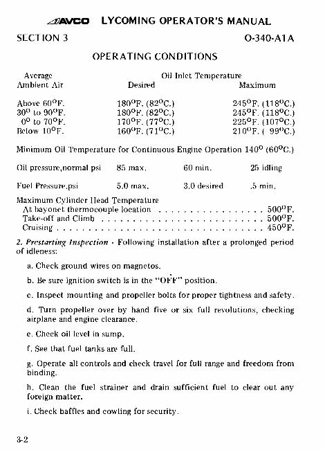
OPERATING CONDITIONS
Average Oil Inlet TemperatureAmbient Air Desired Maximum
Above 60°F. 180°F. (82°C.) 245°F. (118°C.)300 to 90°F. 180°F. (82°C.) 245F. (118°C.)
0° to 70°F. 170 0 F. (77°C.) 225°F. (107C.)Below 10F. 160°F. (71°C.) 210F. ( 99°C.)
Minimum Oil Temperature for Continuous Engine Operation 140 ° (60°C.)
Oil pressure,normal psi 85 max. 60 min. 25 idling
Fuel Pressure,psi 5.0 max. 3.0 desired .5 min.
Maximum Cylinder Head TemperatureAt bayonet thermocouple location ................. 500°F.Take-off and Climb .......................... 500°F.Cruising ................................. 450°F.
2. Prestarting Inspection - Following installation after a prolonged periodof idleness:
a. Check ground wires on magnetos.
b. Be sure ignition switch is in the "OFF" position.
c. Inspect mounting and propeller bolts for proper tightness and safety.
d. Turn propeller over by hand five or six full revolutions, checkingairplane and engine clearance.
e. Check oil level in sump.
f. See that fuel tanks are full.
g. Operate all controls and check travel for full range and freedom frombinding.
h. Clean the fuel strainer and drain sufficient fuel to clear out anyforeign matter.
i. Check baffles and cowling for security.
3-2

AVCO LYCOMING OPERATOR'S MANUAL
0-340-A1A SECTION 3
3. Care of a New Engine - A new engine has been carefully run-in and haspassed a rigid final test at the factory, and no further "Break-In" isnecessary, but the operator will benefit by treating it carefully during itsfirst few hours in service. Avoid prolonged operation at full throttle orexcessive engine speeds.
4. Starting Procedure - After completion of prestarting inspection:
a. Head the airplane into the wind.
b. Lock the wheels by either wheel brakes or chocks.
c. Turn fuel valve to "ON" position.
d. Move mixture control lever to "FULL RICH".
e. Set throttle to 1/10 open position.
f. Prime cold cylinders with one to three full strokes of priming pumpdepending on engine temperature.
g. Engage starter and allow engine to turn approximately one full turnbefore turning ignition switch to the "LEFT MAG" position.
NOTE
Starter manufacturers recommend that cranking periods be limited to tento twelve seconds with a five minute rest between cranking periods.Longer cranking periods will shorten the life of the starter.
h. When engine fires evenly, turn ignition switch to "BOTH" and openthrottle to an indicated speed of 800 RPM. Check oil pressure gage foran indicated pressure. If oil pressure is not indicated within one-halfminute, stop engine and determine trouble.
5. Cold Weather Starting - During extreme cold weather it may benecessary to preheat the engine or the oil before starting. If engine fails tostart at the first attempt, another attempt should be made withoutpriming. If this fails it is possible that the engine is overprimed, turn switchto "OFF" position, open throttle slowly, and turn the engine overapproximately ten revolutions. Prime with half the original prime andrepeat starting procedure. If this fails, refer to Section 6 on EngineTroubles.
3-3

AVCO LYCOMING OPERATOR'S MANUAL
SECTION 3 0-340-A1A
6. Ground Running and Warm-Up - The Avco Lycoming O-340-A1A is anair pressure cooled engine that depends on the forward speed of theairplane to maintain proper cooling. Therefore, particular care is necessarywhen operating this engine on the ground. To prevent overheating it isrecommended that the following precautions be followed:
a. Head airplane into the wind.
b. Avoid prolonged idling at low RPM as this practice may result infouled spark plugs.
c. Do not exceed 1800 RPM during ground test.
d. Limit ground running to 4 minutes in cold weather and to 2 minutesat temperatures above 70°F.
NOTE
Engine is warm enough for take-off when the throttle can be openedwithout back-firing or skipping of the engine.
7. Ground Test
a. Warm up engine 800 to 1200 RPM.
b. With engine running at 1800 RPM, switch from both magnetos toonly one and check drop-off. Then switch to the other magneto andagain note drop-off. Drop-off should not exceed 125 RPM on eithermagneto. On planes with controllable pitch props the drop-off shouldnot exceed 125 RPM when engine is turning 2000 RPM with manifoldpressure of 15 in. hg.
c. Check both oil pressure and oil temperature.
d. Take-off as soon as the test is completed, because excessive groundrunning will cause overheating.
8. Operation in Flight
a. Use of Carburetor Heat Control - Under certain moist atmosphericconditions it is possible for ice to form at the carburetor even insummer weather. For complete instructions on the use of carburetorheat consult the latest publication of Service Instruction No. 1148.
3-4

AVCO LYCOMING OPERATOR'S MANUAL0-340-A1A SECTION 3
b. Carburetor Mixture Control (With Fixed Pitch Prop) - The carburetormixture control should be used to maintain the proper ratio of air andfuel when operating the engine at altitudes above 5000 feet. Under nocircumstances, especially at Full Throttle, should any other positionthan Full-Rich Mixture be used for all flying under 5000 feet above sealevel.
When flying at altitudes above 5000 feet at any throttle setting,adjust the carburetor mixture control toward the "Lean" position untilthe maximum engine RPM is obtained. Too lean a mixture will result inoverheating with subsequent damage to the engine. Care should betaken to readjust the control for each change in the throttle setting and,particularly, to return the mixture control to the "Full-Rich" positionprior to an approach for landing or a descent to a lower altitude.
c. Carburetor Mixture Control (Constant Speed Propeller) - Whenoperating with a constant speed propeller, cylinder head temperatures(rather than engine RPM) provide a means of indicating the point ofoptimum economy. The recommended procedure for leaning out atcruise power (not over 75% rated power) is as follows:
NOTE
Leaning out at cruise power according to the following procedure ispermissible at altitudes under 5000 feet. Under no circumstances,however, is leaning out permitted under 5000 feet at power settings inexcess of 75 per cent.
Set propeller governor and engine throttle at desired RPM andmanifold pressure, with altitude mixture control at "Full Rich". Allowcylinder head temperature to stabilize, and begin leaning out in smallincrements. While observing the cylinder head temperature indicatorclosely, continue to lean out until peak temperature has been reached.
CAUTION
Do not permit cylinder head temperatures to exceed 450°F.
If a sudden temperature rise occurs during leaning out, or ifmaximum permissible temperature is reached, the mixture control levermust be returned (toward Full Rich) to its position prior to thetemperature increase.
3-5

AVCO LYCOMING OPERATOR'S MANUAL
SECTION 3 O-340-A1A
d. Landing - During relatively long glides in making an approach forlanding, the throttle should be partially opened at intervals to clear outengine, and the mixture control kept in full rich position to insuremaximum acceleration if it should be necessary to open the throttleagain.
e. Stopping the Engine - (Note: This engine is equipped with an idlecut off.) After landing, allow the engine to cool by idling forapproximately one minute at 800 to 900 RPM. Then, with the enginestill running at this speed, set the carburetor control at "IDLE CUTOFF". After the engine stops firing, set the ignition switch in the"OFF" position. Stopping an engine in the above method will preventafterfiring.
f. Cold Weather Suggestions:
(1) In extremely cold weather it may be necessary to preheat thelubricating oil prior to starting.
(2) Avoid excessive running of engine on the ground.
(3) To maintain the desired oil temperature, it may be necessary toblock off the oil sump air blast hole or lag sump.
g. Dusty Operation - When operating from dusty fields or in a dustylocation, it will be found a profitable investment to inspect carburetorair intake frequently to make sure that no air enters the carburetorexcept through the air cleaner.
NOTE
Inspect and service air cleaners daily according to manufacturer'sinstructions.
3-6

AVO LYCOMING OPERATOR'S MANUAL
0-340-A1A SECTION 3
OPERATING CONDITIONS FORFIXED PITCH PROPELLER
Fuel Max. *Max.Man. Cons. Oil Cons. Cyl. Head
Operation RPM Pres. Gal./Hr. Qts./Hr. Temp.
Normal Rated 2700 28.7 15.5 .95 500 0 F.**
Performance Cruise 2450 24.2 10.0 .70 450°F.**
Economy Cruise 2350 22.3 8.5 .60 450°F.
* - At bayonet location.
** - Mixture control not to be used below 5000 feet.
3-7

CURVE NO. 10372 A
Figure 3-l. Performance Curve O-340-A1A
3-8

AVCO LYCOMING OPERATOR'S MANUAL
PERIODIC INSPECTIONS
Page
General ..............Inspection and Maintenance
Daily Pre-Flight ......................50-Hour ...... . ..... . ... . ....100-Hour .........................Carburetor Idling Adjustment ..............
. . .4-1
. . .4-1
. . .4-1
. . .4-2. .4-3

AVCO LYCOMING OPERATOR'S MANUAL
O-340-A1A SECTION 4
SECTION 4
PERIODIC INSPECTIONS
1. GENERAL - The daily pre-flight inspection is a check of the completeairplane prior to the first flight of the day. This inspection is to determinethe general condition of the airplane-and engine, but is not designed todetect slight wear and minor maladjustments. Such items should be foundduring the more thorough 50-hour and 100-hour inspections.
The operator should bear in mind that the items listed in the followingcharts constitute a complete inspection only so far as the engine isconcerned; consult the aircraft manufacturer's handbook for completeinstructions.
At the conclusion of the first 25 hours of operation the engine shouldundergo a 50-hour inspection, including the draining and renewing oflubricating oil.
2. INSPECTION AND MAINTENANCE.
a. Daily Pre-Flight -
(1) Check fuel and oil level.
(2) Inspect engine for evidence of oil leakage.
(3) Inspect safetying of oil drain plugs and covers.
(4) Inspect carburetor and fuel line connections.
(5) Check engine controls for general condition, travel, and freeoperation.
(6) Check carburetor air cleaner. Consult per manufacturer'sinstructions.
b. 50-Hour
(1) Check spark plug elbows and shielding nuts for security.
4-1

AVCO LYCOMING OPERATOR'S MANUAL
SECTION 4 O-340-A1A
(2) Drain carburetor bowl.
(3) Check priming system for leaks.
(4) Check oil lines for leaks particularly at connections, security ofanchorage, wear due to rubbing or vibration, dents, and cracks.
(5) Drain and refill oil sump with new oil.
(6) Remove and clean suction and pressure oil strainers.
(7) Check intake and exhaust systems for leaks and looseness.
(8) Drain and clean fuel strainer.
NOTE
All the above operations should be performed in addition to those listedunder Daily Pre-Flight.
c. 100-Hour-
(1) Inspect all electrical wiring for general condition and properanchorage.
(2) Check baffles for secure anchorage, holes, cracks, bending andclose fit around the cylinder.
(3) Check cylinders for cracked or broken fins.
(4) Check air entrances and exits for deformation.
(5) Inspect, clean, and regap spark plugs.
(6) Remove and clean carburetor fuel strainer.
(7) Check magnetos for synchronization.
(8) Check engine mounting bolts and bushings for general conditionand proper torque.
4-2

AVCO LYCOMING OPERATOR'S MANUAL
O-340-A1A SECTION 4
NOTE
All the above operations should be performed in addition to those listedunder Daily Pre-Flight and 50-Hour inspection.
d. Carburetor Idling Adjustment - With exception of the idlingadjustment, no adjustment of the carburetor is necessary. The mixtureis controlled by means of jets and air passages that are not adjustableand are calibrated at the factory.
To adjust the idle mixture and speed: With engine thoroughlywarmed up, set throttle stop screw so that engine idles atapproximately 550 RPM. Turn idle adjusting screw towards "RICH"position until engine "rolls" from richness, then turn screw slowlytowards the "LEAN" position (indicated by letter "L") until engine"lags" or runs "irregularly" from leanness. This step will give an idea ofthe idle adjustment range and of how the engine operates under theseextreme idle mixtures. From the "lean" setting, turn screw slowlytowards a "richer" setting, leaving the final setting at a mixture justlean enough to prevent a rich "roll" or uneven running from richness.This adjustment will in most cases give a slower idle speed than aslightly leaner adjustment, with the same throttle stop screw setting,but will give smoothest idle operation. A change in idle mixture willchange the idle speed, and it may be necessary to readjust the idle speedwith the throttle stop screw to the desired point.
4-3

MAINTENANCE PROCEDURES
Page
Oil Relief Valve .......................... 5-1Magneto Timing ......................... .5-1Cylinders
Removal of Cylinder Assy. ................. .5-5Removal of Valves ...................... .5-5Removal of Pistons ...................... .5-6Removal of Hydraulic Tappets ............... .5-6Cleaning of Hydraulic Tappets ............... .5-6Assy. of Valves ......................... 5-7Assy. of Cylinders ...................... .5-8

AVCO LYCOMING OPERATOR'S MANUAL
O-340-A1A SECTION 5
SECTION 5
MAINTENANCE PROCEDURES
Oil Relief Valve - The function of the oil pressure relief valve, which islocated between the upper right engine mounting lug and no. 3 cylinder, isto maintain engine oil pressure within specified limits by withdrawing aportion of the oil from the circulating system and returning the oil to thesump should the pressure become excessive. This valve is not adjustable;however, particles of metal or other foreign matter lodged between balland seat will result in a drop in oil pressure. It is advisable, therefore, todisassemble, inspect, and clean the relief valve if excessive pressurefluctuations are noted.
The oil pressure relief valve is by no means to be confused with the oilcooler bypass valve, which is located on the oil pressure screen housingmounting pad. The sole purpose of the bypass valve is to serve as a safetymeasure, permitting pressure oil to bypass the oil cooler entirely in case ofan obstruction within the cooler.
Magneto Timing - Remove the top spark plug from the no. 1 cylinder.Place the thumb of one hand over the spark plug hole and rotate thecrankshaft in direction of normal rotation until the compression stroke isreached. The compression stroke is indicated by a positive pressure insidethe cylinder tending to lift the thumb off the spark plug hole. In thisposition both valves of no. 1 cylinder are closed.
Rotate the crankshaft opposite to its normal direction of rotation untilit is approximately 35° before top center of the compression stroke of no.1 cylinder.
Having determined that the engine is beginning the compression strokeon no. 1 cylinder, continue to rotate the crankshaft in its normal directionof rotation until the 25° advance timing mark on the front (propeller) faceof the starter ring gear is in exact alignment with the small hole located atthe two o'clock position on the front face of the starter housing.

AVCO LYCOMING OPERATOR'S MANUAL
SECTION 5 O-340-A1A
Figure 5-1. Ignition Wiring Diagram
5-2
AVCO LYCOMING OPERATOR'S MANUAL
O-340-A1A SECTION 5
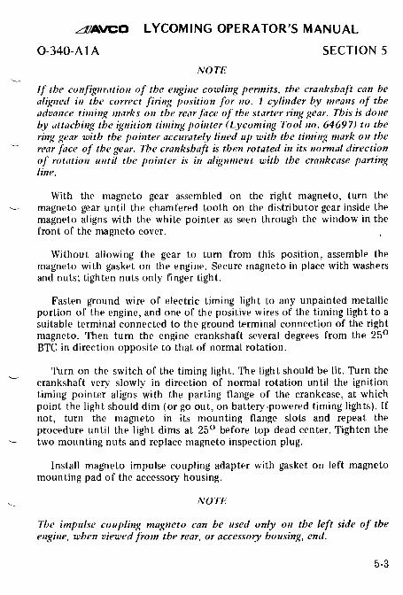
NOTE
If the configuration of the engine cowling permits, the crankshaft can bealigned in the correct firing position for no. I cylinder by means of theadvance timing marks on the rear face of the starter ring gear. This is doneby attaching the ignition timing pointer (Lycoming Tool no. 64697) to thering gear with the pointer accurately lined up with the timing mark on therear face of the gear. The crankshaft is then rotated in its normal directionof rotation until the pointer is in alignment with the crankcase partingline.
With the magneto gear assembled on the right magneto, turn themagneto gear until the chamfered tooth on the distributor gear inside themagneto aligns with the white pointer as seen through the window in thefront of the magneto cover.
Without allowing the gear to turn from this position, assemble themagneto with gasket on the engine. Secure magneto in place with washersand nuts; tighten nuts only finger tight.
Fasten ground wire of electric timing light to any unpainted metallicportion of the engine, and one of the positive wires of the timing light to asuitable terminal connected to the ground terminal connection of the rightmagneto. Then turn the engine crankshaft several degrees from the 25 °
BTC in direction opposite to that of normal rotation.
Turn on the switch of the timing light. The light should be lit. Turn thecrankshaft very slowly in direction of normal rotation until the ignitiontiming pointer aligns with the parting flange of the crankcase, at whichpoint the light should dim (or go out, on battery-powered timing lights). Ifnot, turn the magneto in its mounting flange slots and repeat theprocedure until the light dims at 25 ° before top dead center. Tighten thetwo mounting nuts and replace magneto inspection plug.
Install magneto impulse coupling adapter with gasket on left magnetomounting pad of the accessory housing.
NOTE
The impulse coupling magneto can be used only on the left side of theengine, when viewed from the rear, or accessory housing, end.
5-3

AVCO LYCOMING OPERATOR'S MANUAL
SECTION 5 0-340-A1A
Remove inspection plug and turn magneto drive coupling until thewhite beveled tooth on the magneto gear aligns with the pointer.
NOTE
In order to turn the shaft on the impulse coupling magneto, depress thepawl on the impulse coupling with the finger.
Place magneto gasket over mounting studs and secure left magneto inplace with washers and nuts; tighten nuts only finger tight.
Connect the other positive wire of the timing light to a suitableterminal connected to the ground terminal connection of the left magnetoand time the magneto in the same manner as described for the rightmagneto.
NOTE
The crankshaft should not be rotated more than 35 in direction oppositenormal rotation, as the pawl on the impulse coupling will engage with thestop pin and late timing will be indicated through the impulse couplingmechanism. If this should happen, rotate engine in normal direction untilsharp click is heard, which will indicate that impulse coupling has passedthrough firing position; then turn crankshaft in direction opposite normalrotation to approximately 35 ° before top center and proceed with timingcheck.
After both magnetos have been timed, leave the timing light wiresconnected and re-check magneto timing as previously described to makesure that both magnetos are set to fire together. If timing is correct, bothtiming lights will dim simultaneously when the advance timing marks onthe front of the engine are in exact alignment. If the breaker points opentoo early, loosen the mounting nuts and rotate the magneto clockwise. Ifthe breaker points open too late, rotate the magneto counterclockwise.
After magnetos have been properly timed, clean the breaker points toremove any trace of oil or dirt. Replace breaker cover and lock theretaining screws together with lockwire.
5-4

AVCO LYCOMING OPERATOR'S MANUAL
0-340-A1A SECTION 5
NOTE
Breaker points on Bendix Scintilla S4LN type magnetos are not to beadjusted to a given clearance. For proper S4LN magneto adjustments, referto Scintilla's instructions.
Removal of Cylinder Assembly -
a. Remove exhaust manifold.
b. Remove rocker box drain tube, intake pipe, baffles, priming lines,and any clips that interfere with the removal of cylinder.
c. Disconnect ignition cable and remove spark plugs. Remove rockerbox cover and rotate crankshaft until piston is approximately at topcenter of the compression stroke. This approximate position may belocated by observing top of the piston through the spark plug hole andalso watching the valve action.
d. Remove valve rockers by sliding valve rocker shaft out of thecylinder head.
e. Remove push rods by grasping ball end and pulling rod out of shroudtube. Detach shroud tube springs and lockplate and pull shroud tubesout through holes in cylinder head.
f. Remove cylinder base nuts and plates and remove cylinder by pullingcylinder directly away from crankcase. Be careful not to allow thepiston to drop against the crankcase as the piston leaves the cylinder.
NOTE
The hydraulic tappets, push rods, rocker arms, and valves must be markedso that they can be assembled in the same location from which they wereremoved.
Removal of Valves and Valve Springs from Cylinder - Place the cylinderover a block of wood so as to hold the valves in a closed position.Compress the valve springs using the valve spring compressor. Remove thesplit keys from the end of the valve stem. The valve springs and valvespring seats may now be removed from the cylinder head. Hold the valvestems so that the valves will not fall out and remove the cylinder from theholding block. The valves may now be removed from the inside of thecylinder.
5-5

AVCO LYCOMING OPERATOR'S MANUAL
SECTION 5 O-340-A1A
Removal of Piston from Connecting Rod - Remove piston pin plugs fromthe piston. Insert piston pin puller through piston pin, assemble puller nut;then proceed to remove piston pin. Do not allow connecting rod to rest onthe cylinder bore of the crankcase. Support with heavy rubber bands,discarded cylinder base oil ring seals, or any other non-marring means ofsupport.
Removal of Hydraulic Tappet Sockets and Plunger Assemblies - Thehydraulic tappet socket may usually be removed by inserting theforefinger into the concave end of the socket. The socket will usually stickto the finger firmly enough to be pulled out of the tappet body. If thesocket cannot be removed in this manner, it may be removed by graspingthe edge of the socket with a pair of needle nose pliers. However, careshould be exercised to avoid scratching the socket. To remove thehydraulic tappet plunger assembly, use service tool 64941 or if notavailable, bend a hook in the end of a short piece of lock wire, insert thelock wire around the edge of the plunger assembly and turn the wire sothat the hook engages the spring of the plunger assembly. Draw theplunger assembly out of the tappet body by pulling gently on the wire.
Cleaning and Inspection of Hydraulic Tappet Plunger AssemblyDisassemble hydraulic tappet plunger assembly by grasping the tube end ofthe plunger assembly in one hand and the spring end in the other. Removethe plunger by twisting the spring end of the plunger assembly in aclockwise direction and pulling the plunger out of the tube.
CAUTION
Do not allow parts of two or more plunger assemblies to become mixed, asthe parts of the plunger assembly are selectively fitted during manufactureand are not interchangeable.
Clean the plunger assembly by flushing with petroleum solvent. Workthe plunger up and down while the unit is immersed in the solvent, holdingthe check valve off its seat by means of a copper wire or other relativelysoft article inserted through the tube. Do not use a blast of air or pressurespray to clean the plunger assembly, as damage to the check valve andcheck valve seat may result.
5-6

AVCO LYCOMING OPERATOR'S MANUAL
O-340-A1A SECTION 5
Thoroughly dry the plunger assembly and start the plunger into thecylinder. Check the operation of the plunger assembly by depressing andreleasing the plunger with one finger. On a serviceable plunger assembly,the plunger will spring back if pressure is released immediately after theplunger is depressed. This is caused by the air trapped inside the plungerassembly. If the plunger assembly, when pushed down by the finger, doesnot have a "springy" feel and stays at the bottom when released, the checkvalve is leaking, or the plunger assembly is worn and will not hold airunder the plunger. If the plunger assembly fails to pass inspection asoutlined above, clean the plunger assembly as directed in precedingparagraph and repeat the check. If the plunger assembly still fails to passinspection, it should be rejected and replaced with a new plungerassembly.
NOTE
The above inspection procedure must be made with the plunger assemblyabsolutely dry and free from oil or cleaning solvent.
The plunger assembly should be reassembled without oil. This may beaccomplished by placing the plunger in position, compressing the springslightly, and at the same time twisting the spring end of the plunger in aclockwise direction until the spring is felt to click into place.
Assembly of Valves in Cylinder - Insert each valve stem in its respectiveguide. Place cylinder over a wood block so that the valves are held againstthe seats and assemble the lower spring seat, auxiliary valve spring andouter valve spring over the valve stem and guide. Place the upper springseat on top of the springs.
NOTE
When installing valve springs, place the dampener end of spring towardcylinder. The dampencr end of the spring may be identified as the end ofthe spring that has less spacing between the coils.
Using valve spring compressor, compress the valve springs and assemblethe two valve keys into the groove around the upper end of the valve stem.Slowly release the pressure on the valve spring compressor and allow theupper spring seat to lock itself in place around the valve keys.
5-7
AVCO LYCOMING OPERATOR'S MANUAL
SECTION 5 0-340-A1A
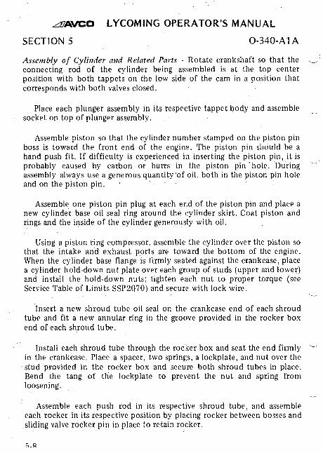
Assembly of Cylinder and Related Parts - Rotate crankshaft so that theconnecting rod of the cylinder being assembled is at the top centerposition with both tappets on the low side of the cam in a position thatcorresponds with both valves closed.
Place each plunger assembly in its respective tappet body and assemblesocket on top of plunger assembly.
Assemble piston so that the cylinder number stamped on the piston pinboss is toward the front end of the engine. The piston pin should be ahand push fit. If difficulty is experienced in inserting the piston pin, it isprobably caused by carbon or burrs in the piston pin 'hole. Duringassembly always use a generous quantity of oil, both in the piston pin holeand on the piston pin.
Assemble one piston pin plug at each end of the piston pin and place anew cylinder base oil seal ring around the cylinder skirt. Coat piston andrings and the inside of the cylinder generously with oil.
Using a piston ring compressor, assemble the cylinder over the piston sothat the intake and exhaust ports are toward the bottom of the engine.When the cylinder base flange is firmly seated against the crankcase, placea cylinder hold-down nut plate over each group of studs (upper and lower)and install the hold-down nuts; tighten each nut to proper torque (seeService Table of Limits SSP2070) and secure with lock wire.
Insert a new shroud tube oil seal on the crankcase end of each shroudtube and fit a new annular ring in the groove provided in the rocker boxend of each shroud tube.
Install each shroud tube through the rocker box and seat the end firmlyin the crankcase. Place a spacer, two springs, a lockplate, and nut over thestud provided in the rocker box and secure both shroud tubes in place.Bend the tang of the lockplate to prevent the nut and spring fromloosening.
Assemble each push rod in its respective shroud tube, and assembleeach rocker in its respective position by placing rocker between bosses andsliding valve rocker pin in place to retain rocker.

AVCO LYCOMING OPERATOR'S MANUAL
0-340-A1A SECTION 5
Be sure that the piston is at top center compression stroke and thatboth valves are closed. Check clearance between the valve stem tip and thevalve rocker. In order to check this clearance, place the thumb of one handon the valve rocker directly over the end of the push rod and push downso as to compress the hydraulic tappet spring. While holding the springcompressed, check valve clearance, which should be between .028 and.080 inch. If the clearance does not come within these limits, remove thepush rod and insert a longer or shorter push rod as required to correctclearance. Push rods are made in four lengths; the shortest rod is markedwith three grooves at one end, the next longer rod is marked with twogrooves, the third rod is marked with one groove, and the longest rod isunmarked.
NOTE
Inserting a longer rod will cause a descrease in the valve clearance.
5-9

AVCO LYCOMING OPERATOR'S MANUAL
TROUBLE-SHOOTING
Page
Failure of Engine to Start .................... 6-1Failure of Engine to Idle Properly .............. .6-2Low Power and Uneven Running ............... .6-2Failure of Engine to Develop Full
Power .............................. 6-3Rough Engine ........................... 6-4Low Oil Pressure ........................ .6-4High Oil Temperature ..................... .6-5Excessive Oil Consumption ................... 6-5Cold Weather Difficulties ................... .6-6

AVCO LYCOMING OPERATOR'S MANUAL
0-340-A1A SECTION 6
SECTION 6
TROUBLE-SHOOTING
General - Experience has proven that the best method of"trouble-shooting" is to decide on the various possible causes of a giventrouble and then to eliminate these causes one by one, beginning with themost probable. The following chart lists some of the more common enginetroubles usually found in maintaining aircraft engines.
TROUBLE PROBABLE CAUSE REMEDY
Failure of Engineto Start
Lack of fuel
Underpriming
Overpriming
Incorrect throttlesetting
Check fuel system for leaks.Fill fuel tank. Clean dirtylines, strainers or fuel cocks.
Prime with 2 or 3 strokesprimer.
Open throttle and "unload"engine by turning in counter-clockwise direction.
Open throttle to one-tenthof its range.
Defective sparkplugs
Defective ignitionwire
Defective battery
Improper operationof magneto breakerpoints
Clean and adjust or replacespark plug or plugs.
Check with electric tester,and replace any defectivewires.
Replace with charged battery.
Clean points. Check internaltiming of magnetos.

AVCO LYCOMING OPERATOR'S MANUAL
SECTION 6
TROUBLE
Failure of Engineto Start (Cont.)
PROBABLE CAUSE
Water in carburetor
O-340-A1A
REMEDY
Drain carburetor and fuellines.
Internal failure Check oil sump strainer formetal particles. If found,complete overhaul of theengine may be indicated.
Failure of Engineto Idle Properly
Incorrect carburetoridle adjustment
Adjust throttle stop to ob-tain correct idle.
Idle mixture
Leak in the induc-tion system
Low cylindercompression
Faulty ignitionsystem
Adjust mixture - refer toSection 5, this handbook.
Tighten all connections inthe induction system.Replaceany parts that are defective.
Check condition of pistonrings and valve seats.
Check entire ignitionsystem
Low Power andUneven Running
Mixture too rich;indicated by slug-gish engine operation,red exhaust flame atnight. Extreme casesindicated by blacksmoke from exhaust
Check primer shut-off valvefor leakage. Readjustmentof carburetor by authorizedpersonnel is indicated.
Mixture too lean;indicated by over-heating or back-firing
Leaks in inductionsystem
Check fuel lines for dirtor other restrictions.Checkfuel supply.
Tighten all connections.Re-place defective parts.
6-2

AVCO LYCOMING OPERATOR'S MANUAL
0-340-A1 A
TROUBLE
Low Power andUneven Running(Cont.)
PROBABLE CAUSE
Defective sparkplugs
SECTION 6
REMEDY
Clean or replace spark plugs.
Poor fuel
Magneto breakerpoints not workingproperly
Defective ignitionwire
Improper ignitiontiming
Defective sparkplug terminalconnectors
Incorrect valveclearance
Incorrect valvetiming
Fill tank with fuel of recom-mended grade.
Clean points.Check internaltiming of magnetos.
Check wire with electrictester.Replace defectivewire.
Check magnetos for timingand synchronization.
Replace connectors on sparkplug wire.
Adjust valve clearance.
Check valve timing.
Failure of Engineto Develop FullPower
Throttle lever outof adjustment
Adjust throttle lever.
Leak in the induc-tion system
Restriction incarburetor airscoop
Improper fuel
Tighten all connections,andreplace defective parts.
Examine air scoop andremove restrictions.
Fill tank with recommendedfuel.
6-3

AVCO LYCOMING OPERATOR'S MANUAL
SECTION 6 0-340-A1 A
TROUBLE PROBABLE CAUSE REMEDY
Failure of Engineto Develop FullPower (Cont.)
Rough Engine
Faulty ignition
Cracked enginemount
Tighten all connections.Check system with tester.Check ignition timing.
Replace or repair mount.
Unbalancedpropeller
Remove propeller and haveit checked for balance.
Low OilPressure
Defective mountingbushings
Malfunctioningengine
Insufficient oil
Air lock or dirtin relief valve
Leak in suctionline or pressureline
Dirty oilstrainers
High oiltemperature
Defective pres-sure gage
Install new mountingbushings.
Check entire engine.
Check oil supply.
Remove and clean oilpressure relief valve.
Check gasket between accy.housing and crankcase.
Remove and clean oilstrainers.
See "High Oil Temperature"in "Trouble" column.
Replace gage.
Stoppage in oilpump intakepassage
Check line for obstruction.Clean suction strainer.

AVCO LYCOMING OPERATOR'S MANUAL
0-340-Al A
TROUBLE
High OilTemperature
PROBABLE CAUSE
Insufficient aircooling
SECTION 6
REMEDY
Check air inlet and outletfor deformation or obstruc-tion.
Insufficient oilsupply
Low grade of oil
Clogged oil linesor strainers
Excessive blow-by
Failing or failedbearing
Improper engineoperation
Defective tempera-ture gage
Fill oil sump to proper level.
Replace with oil conformingto specification.
Remove and clean oilstrainers.
Usually caused by worn orstuck rings. Complete over-haul required.
Examine sump for metalparticles. If found,over-haul of engine is indicated.
Check entire engine.
Replace gage.
Excessive OilConsumption
Low grade of oil Fill tank with oil conformingto specification.
Failing or failedbearing
Worn piston rings
Incorrect installation of pistonrings
Check sump for metalparticles. If found, over-haul engine.
Install new rings.
Install new rings.

AVCO LYCOMING OPERATOR'S MANUAL
SECTION 6
TROUBLE
Cold WeatherDifficulties
0-340-A1A
PROBABLE CAUSE REMEDY
Cold oil Move aircraft into a heatedhangar. Heat oil.
Inaccurate pres-sure readings
Overpriming
Weak battery
In extreme cold weather oilpressure readings up to ap-proximately 100 lbs.do notnecessarily indicate malfunc-tioning.
Rotate crankshaft in counter-clockwise direction withthrottle "FULL OPEN" andignition switch "OFF".
Install fully charged battery.
6-6

AVCO LYCOMING OPERATOR'S MANUAL
INSTALLATION AND STORAGE
Page
Preparation for Installation ........General .........Inspection of Engine Mtg ........Attaching Engine to Mounts .......Oil and Fuel Line Connections .....Propeller Installation ...........
Preparation of Carbs. and FuelInjectors for Installation .........
Corrosion Prevention in EnginesInstalled in Inactive Aircraft .......
. . . . . . . . . . .7-1
. . . . . . . . . . .7-2
. . . . . . . . . . .7-2
. . . . . . . . . . .7-2
. . . . . . . . . . .7-2
. . . . . . . . . . .7-2
. . . . . . . . . . .7-2
.7-3

AVCO LYCOMING OPERATOR'S MANUAL
0-340-A1A SECTION 7
SECTION 7
INSTALLATION AND STORAGE
1. PREPARAION OF ENGINE I OR INSTALLATION. Before installingan engine that has been prepared for storage, remove all dehydrator plugs,bags of dessicant and preservative oil from the engine. Preservation oil canbe removed by removing the bottom spark plugs and turning thecrankshaft three or four revolutions by hand. The preservative oil will thendrain through the spark plug holes. Draining will be facilitated if theengine is tilted from side to side during the above operation. Preservativeoil which has accumulated in the sump can be drained by removing the oilsump plug. Engines that have been stored in a cold place should beremoved to an environment of at least 70°F. (21°C.) for a period of 24hours before preservative oil is drained from the cylinders. If this is notpossible, heat the cylinders with heat lamps before attempting to drain theengine.
After the oil sump has been drained, the plug should be replaced,safety-wired, and the sump refilled with lubricating oil. The crankshaftshould again be turned several revolutions to saturate the interior of theengine with the clean oil. When installing spark plugs, make sure that theyare clean, if not, wash them in clean petroleum solvent. Of course, therewill be a small amount of preservative oil remaining in the engine, but thiscan cause no harm. However, after twenty-five hours of operation, thelubricating oil should be drained while the engine is hot. This will removeany residual preservative oil that may have been present.
CA UTION
Do not rotate the crankshaft of an engine containing preservative oilbefore removing the spark plugs, because if the cylinders contain anyappreciable amount of the mixture, the resulting action, known ashydraulicing, will cause damage to the engine. Also, any contact of thepreservative oil with painted surfaces should be avoided.

AVCO LYCOMING OPERATOR'S MANUAL
SECTION 7 0-340-A1A
General - Should any of the dehydrator plugs, containing crystals ofsilica-gel or similar material, be broken during their term of storage orupon their removal from the engine, and if any of the contents should fallinto the engine, that portion of the engine must be disassembled andthoroughly cleaned before using the engine. The oil strainers should beremoved and cleaned in gasoline or some other hydrocarbon solvent. Thefuel drain screen located in the fuel inlet of the carburetor or fuel injectorshould also be removed and cleaned in a hydrocarbon solvent. Theoperator should also note if any valves are sticking. If they are, thiscondition can be eliminated by coating the valve stem generously with amixture of gasoline and lubrication oil.
Inspection of Engine Mounting - If the aircraft is one from which anengine has been removed, make sure that the engine mount is not bent ordamaged by distortion or misalignment as this can produce abnormalstresses within the engine.
Attaching Engine to Mounts - See airframe manufacturer'srecommendations for method of mounting the engine.
Oil and Fuel Line Connections - The oil and fuel line connections arecalled out on the accompanying installation drawings.
Propeller Installation - Consult the airframe manufacturer for informationrelative to propeller installation.
2. PREPARATION OF CARBURETORS AND FUEL INJECTORS FORINS TA .I.A TION.
Carburetors and fuel injectors that have been prepared for storageshould undergo the following procedures before being placed in service.
Carburetor (MA-4-5) - Remove the fuel drain plug and drain preservativeoil. Remove the fuel inlet strainer assembly and clean in a hydrocarbonsolvent. Reinstall the fuel drain plug and fuel inlet strainer assembly.
Fuel Injector (Bendix) - Remove and clean the fuel inlet strainer assemblyand reinstall. Inject clean fuel into the fuel inlet connection with the fueloutlets uncapped until clean fuel flows from the outlets. Do not exceed 15psi inlet pressure.
7-2

AVCO LYCOMING OPERATOR'S MANUAL
0-340-A1A SECTION 7
CORROSION PREVENTION IN ENGINES INSTALLEDIN INACTIVE AIRCRAFT
Corrosion can occur, especially in new or overhauled engines, oncylinder walls of engines that will be inoperative for periods as brief as twodays. Therefore, the following preservation procedure is recommended forinactive engines and will be effective in minimizing the corrosion conditionfor a period up to thirty days.
NOTE
Ground running the engine for brief periods of time is not a substitute forthe following procedure; in fact, the practice of ground running will tendto aggravate rather than minimize this corrosion condition.
a. As soon as possible after the engine is stopped, move the aircraft intothe hangar, or other shelter where the preservation process is to beperformed.
b. Remove sufficient cowling to gain access to the spark plugs andremove both spark plugs from each cylinder.
c. Spray the interior of each cylinder with approximately (2) ounces ofcorrosion preventive oil while cranking the engine about five (5)revolutions with the starter. The spray gun nozzle may be placed ineither of the spark plug holes.
d. Consult the latest edition of Service Letter No. L180 for detailedinformation on preservation for active and stored aircraft.
NOTE
Spraying should be accomplished using an airless spray gun (SprayingSystems Co., "Gunjet" Model 24A-8395 or equivalent). In the event anairless spray gun is not available, personnel should install a moisture trap inthe air line of a conventional spray gun and be certain oil is hot at thenozzle before spraying cylinders.
e. With the crankshaft stationary, again spray each cylinder through thespark plug holes with approximately two ounces of corrosionpreventive oil. Assemble spark plugs and do not turn crankshaft aftercylinders have been sprayed.
7-3

AVCO LYCOMING OPERATOR'S MANUAL
SECTION 7 O-340-A1A
The corrosion preventive oil to be used in the foregoing procedureshould conform to specification MIL-L-6529, Type 1 heated to200°F./220°F. (93°C./104°C.) spray nozzle temperature. It is notnecessary to flush preservative oil from the cylinder prior to flying theaircraft. The small quantity of oil coating the cylinders will be expelledfrom the engine during the first few minutes of operation.
NOTE
Oils of the type mentioned are to be used in Avco Lycoming aircraftengines for corrosion prevention only, and not for lubrication. See thelatest edition of Avco Lycoming Service Instruction No. 1014 and ServiceBulletin No. 318 for recommended lubricating oil.
7-4

AVCO LYCOMING OPERATOR'S MANUAL
0-340-A1 A SECTION 7
Figure 7-1. Longitudinal Section - 0-340-A1A
7-5

AVCO
SECTION 7
LYCOMING OPERATOR'S MANUAL
0-340-A1 A
Figure 7-2. Accessory Drive Section - 0-340-A1A
Figure 7-3. Transverse Section - 0-340-A1A
7-6
AVCO LYCOMING OPERATOR'S MANUAL
TABLES
Page
Table of Limits ...........Fixed Wing Only ..........Flight Test After Top Overhaul . .Full Throttle HP at Altitude ....Table of Speed Equivalents ....Centigrade-Fahrenheit ConversionInch-Fractions Conversions ....
............. .8-1
.............. .8-2
.............. .8-3
.............. .8-4
.............. .8-4
.............. .8-5
.............. .8-6

AVCO LYCOMING OPERATOR'S MANUAL
0-340-A1 A SECTION 8
SECTION 8
TABLES
FOR TIGHTENING TORQUE RECOMMENDATIONS AND
INFORMATION CONCERNING TOLERANCES AND DIMENSIONS
THAT MUST BE MAINTAINED IN AVCO LYCOMING AIRCRAFT
ENGINES, CONSULT LATEST EDITION OF SPECIAL SERVICE
PUBLICATION NO. SSP2070.
CONSULT LATEST EDITION OF SERVICE INSTRUCTION NO.
1029 AND NO. 1150 FOR INFORMATION PERTINENT TO
CORRECTLY INSTALLING CYLINDER ASSEMBLY.
8-1

FIXED WING ONLY
GROUND RUN AFTER TOP OVERHAULOR CYLINDER CHANGE WITH NEW RINGS
(DO NOT USE AFTER MAJOR OVERHAUL)
1. Avoid dust\ location and loose stones.2. Head aircraft into wind.3. All cowling should be in place, cowl flaps open.4. Accomplish ground run in full flat pitch.5. Never exceed 200°F. oil temperature.6. If cylinder head temperatures reach 400°F. shutdown and allow engine to cool before continuing.
Type Aircraft
Registration No.
Aircraft No.
Owner
m
zoo
a
Engine Model S:N
Date
Run-Up By
GROUND RUNTemperature Pressure Temperature Fuel Flow
Time RPM MAP L.oil R.oil L.cyl R.cyl L.oil R.oil L.fuel R.fuel L.carb R.carb Amb.Air Left Right5 min 1000
10 min 120010 min 1300
5 min 15005 min 16005 min 17005 min 1800
r-
0
Mag. Check
Power Check
Adjustment Required After Completion of Ground Run
1. Visually inspect engine(s)2. Check oil level(s)
>Idle Check

9
FLIGHT TEST AFTER TOP OVERHAULOR CYLINDER CHANGE WITH NEW RINGS
1. Test fly aircraft one hour.2. Use standard power for climb, and at least 75% power for cruise.3. Make climb shallow and at good airspeed for cooling.4. Record engine instrument readings during climb and cruise.
Tested by
FLIGHT TEST RECORD ZTemperature Pressure Temperature Fuel Flow
Time RPM MAP L.oil R.oil L.cyl R.cyl L.oil R.oil L.fuel R.fuel L.carb R.carb Amb.Air Left Right(Climb)Cruise
Adjustments Required After Flight After Test Flight
1. Make careful visual inspection of engine(s).2. Check oil level(s).3. If oil Consumption is excessive, (see operator's >manual for limits), remove spark plugs and checkcylinder barrels for scoring.
z

AVCO LYCOMING OPERATOR'S MANUAL
SECTION 8 0-340-A1 A
FULL THROTTLE HP AT ALTITUDE(Normally Aspirated Engines)
Altitude % S. L. Altitude % S. L. Altitude % S. L.Ft. H. P. Ft. H. P. Ft. H. P.
0500
1,0002,0002,5003,0004,0005,0006,0007,0008,0009,000
10098.596.893.692.090.587.584.681.778.976.273.5
10,00011,00012,00013,00014,00015,00016,00017,00017,50018,00018,50019,000
70.868.365.863.461.058.756.554.353.152.151.450.0
19,50020,00020,50021,00021,50022,00022,50023,00023,50024,00024,50025,000
49.148.047.646.045.244.043.342.241.440.339.538.5
TABLE OF SPEED EQUIVALENTS
Sec./Mi. M. P. H. Sec./Mi. M. P. H. Sec./Mi. M. P. H.
72.060.051.445.040.036.032.730.027.725.7
5060708090
100110120130140
24.022.521.220.018.918.017.116.415.615.0
150160170180190200210220230240
14.413.813.312.812.412.011.611.210.910.6
250260270280290300310320330340
8-4

AVCO LYCOMING OPERATOR'S MANUAL
0-340-A1 A SECTION 8
CENTIGRADE-FAHRENHEIT CONVERSION TABLE
Example: To convert 20°C. to Fahrenheit, find 20 in the center columnheaded (F-C); then read 68.0°F. in the column (F) to the right. Toconvert 20°F. to Centigrade; find 20 in the center column and read-6.61°C. in the (C) column to the left.
C F-C
-56.7-51.1-45.6-40.0-34.0-28.9-23.3-17.8
-12.22-6.67-1.114.44
10.0015.5621.1126.6732.2237.7843.3348.8954.4460.0065.5671.0076.6782.2287.7893.3398.89
-70-60-50-40-30-20-10
0102030405060708090
100110120130140150160170180190200210
F
-94.0-76.0-58.0-40.0-22.0
-4.014.032.050.068.086.0
104.0122.0140.0158.0176.0194.0212.0230.0248.0266.0284.0302.0320.0338.0356.0374.0392.0410.0
C F-C F
104.44110.00115.56121.11126.67132.22137.78143.33148.89154.44160.00165.56171.11176.67182.22187.78193.33198.89204.44210.00215.56221.11226.67232.22257.78243.33248.89254.44260.00
220230240250260270280290300310320330340350360370380390400410420430440450460470480490500
428.0446.0464.0482.0500.0518.0536.0554.0572.0590.0608.0626.0644.0662.0680.0698.0716.0734.0752.0770.0788.0806.0824.0842.0860.0878.0896.0914.0932.0
8-5
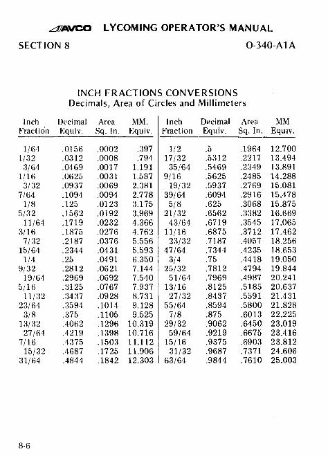
AVCO LYCOMING OPERATOR'S MANUAL
SECTION 8 0-340-A1A
INCH FRACTIONS CONVERSIONSDecimals, Area of Circles and Millimeters
Inch Decimal Area MM. Inch Decimal Area MMFraction Equiv. Sq. In. Equiv. Fraction Equiv. Sq. In. Equiv.
1/64 .0156 .0002 .397 1/2 .5 .1964 12.7001/32 .0312 .0008 .794 17/32 .5312 .2217 13.4943/64 .0469 .0017 1.191 35/64 .5469 .2349 13.891
1/16 .0625 .0031 1.587 9/16 .5625 .2485 14.2883/32 .0937 .0069 2.381 19/32 .5937 .2769 15.081
7/64 .1094 .0094 2.778 39/64 .6094 .2916 15.4781/8 .125 .0123 3.175 5/8 .625 .3068 15.875
5/32 .1562 .0192 3.969 21/32 .6562 .3382 16.66911/64 .1719 .0232 4.366 43/64 .6719 .3545 17.065
3/16 .1875 .0276 4.762 11/16 .6875 .3712 17.4627/32 .2187 .0376 5.556 23/32 .7187 .4057 18.256
15/64 .2344 .0431 5.593 47/64 .7344 .4235 18.6531/4 .25 .0491 6.350 3/4 .75 .4418 19.050
9/32 .2812 .0621 7.144 25/32 .7812 .4794 19.84419/64 .2969 .0692 7.540 51/64 .7969 .4987 20.241
5/16 .3125 .0767 7.937 13/16 .8125 .5185 20.63711/32 .3437 .0928 8.731 27/32 .8437 .5591 21.431
23/64 .3594 .1014 9.128 55/64 .8594 .5800 21.8283/8 .375 .1105 9.525 7/8 .875 .6013 22.225
13/32 .4062 .1296 10.319 29/32 .9062 .6450 23.01927/64 .4219 .1398 10.716 59/64 .9219 .6675 23.416
7/16 .4375 .1503 11.112 15/16 .9375 .6903 23.81215/32 .4687 .1725 11.906 31/32 .9687 .7371 24.606
31/64 .4844 .1842 12.303 63/64 .9844 .7610 25.003