58255066 westfalia separator ag
DESCRIPTION
MarineTRANSCRIPT
Westfalia Separator AG
lnst ruct ion Manual andParts List
e .
II
- l
IQ*
ffiIcdrlical Separationttvi*rn
:r::ii
N o . 2 0 4 4 - 9 0 0 1 - 2 0 1
Ed r t ron 0699
M i n e r a l o i l s e p a r a t o rw i t h s e l t - c l e a n i n g b o w l
M o d e l O S C s 0 - 0 1 3 6 - 0 6 6 H ' ' : {
o s c 5 0 . 0 1 3 6 - 5 6 6OSC 50 -91 -066 L - . t s I ' l / {
F *
, iit

Westfalia Separator AG I l
A p p l i c a t i o n :o Separation of l iquid mixtures
0 ro Clarif ication of l iquids
Subject to modif ication
Westfalia Separator AGD-59302 Oelde (F. R, Germany)
Type
bui l t ininner O otbowl mm
Rpm of bowl
Permissible density of productto be treated
heavy l iquidkg/dm3
sol idskgidms
IV Westfalia Separator AG
AN
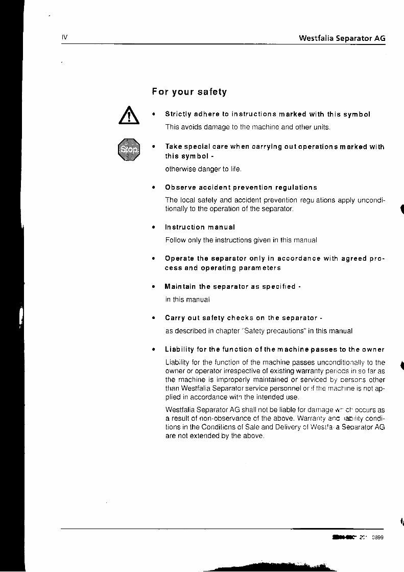
F o r y o u r s a f e t y
S t r i c t l y a d h e r e t o i n s t r u c t i o n s m a r k e d w i t h t h i s s y m b o l
This avoids damage to the machine and other units.
T a k e s p e c i a l c a r e w h e n c a r r y i n g o u t o p e r a t i o n s m a r k e d w i t ht h i s s y m b o l -
otherwise danger to l i fe,
O b s e r v e a c c i d e n t p r e v e n t i o n r e g u l a t i o n s
The local safety and accident prevention regulations apply uncondi-tionally to the operation of the separator.
l n s t r u c t i o n m a n u a l
Follow only the instructions given in this manual
O p e r a t e t h e s e p a r a t o r o n l y i n a c c o r d a n c e w i t h a g r e e d p r o -c e s s a n d o p e r a t i n g p a r a m e t e r s
M a i n t a i n t h e s e p a r a t o r a s s p e c i f i e d -
in th is manual
C a r r y o u t s a l e t y c h e c k s o n t h e s e p a r a t o r -
as described in chapter "Safety precautions" in this manual
L i a b i l i t y f o r t h e f u n c t i o n o f t h e m a c h i n e p a s s e s t o t h e o w n e r
Liabil i ty for the function of the machine passes uncondit ionally to theowner or operator irrespective of exist ing warranty periods in so far asthe machine is improperly maintained or serviced by oerscns otherthan Westfal ia Separator service personnel or i f the macnrne is not ap-ol ied in accordance with the intended use.
Westfal ia Separator AG shall not be l iable for damage rf- ch occurs asa result of non-observance of the above. Warranty anc rabrl i ty condi-t ions in the Condit ions of Sale and Deliverv of Westia ia Seoarator AGare not extended by the above.
ttF ?:' 0699

)
)r
J
i-2
Westfalia Separator AG
Safe ty p recau t i on sCorrect usage .Safety stickers on the machineBasic operat ing pr inciplesBowl speed and productOperations on the separatorAssemblyElectrical appliancesBefore start-upOperationShut-down and " Emergency-Off"
1.5.6 Maintenance and reoair1.6 Cor ros ion1.7 Eros ion
M a c h i n e d e s c r i p t i o n . 1 7
t . I
1 . 2
1 . 41 . 51 . 5 . 11 . 5 . 21 . 5 31 F A
1 . 5 . 5
1
z
a
4
q
I J1 A
2 1
22
23
2425z o
2828.JU
3232J Z
3 5
J /
37383838
4041
2 , 12 . 1 . 1
Appl icat ionCentrifuge with watefuel oi l t reatment . .
r content monitoring system (WMS) for
Technical informationSeparationNotes on separation with the purifier bowl (-02- operation) . .Make-uo waterNotes on seoaration with the clarifier bowl .General information on bowl ejectionsBefore start-uo
2.1.2 Centri fuge with sludge space monitoring system (SMS) forfuel oi l treatment
2.1.3 Centr i fuge with sludge space monitor ing system (SMS) forlube oi l t reatmentComoonents of the 0lant and the seoaratorTechnical DataOperating principles of the separatorOperating principles of the bowl . . .Operat ing pr inciples of the hydraul ical ly control led sl id ing piston . .Operating principles of the centripetal pumpOperating principles of the gearOperating principles of the centrifugal clutch
2.5 The regulat ing r ing2.5.1 Determining the size of regulating r ing by experiment
a . a
2.32 . 42 . 4 12 . 4 . 22 .4 .32 .4 .42 .4 .5
O p e r a t i o nJ . l
3 . 1 . 13 . 1 2U , I , U
3 , 1 ' 4
J . Z
3 . 2 . 13 , 2 , 23 .33 , 43 . 53 . 5 . 1. t . oa 7
Before initial start-upWhenever starting .Start-up of separatorMon itori ng of operationSetting the separating timeDetermining the separating t ime by calculationBowl ejectionsStopping the separator
i 1- l
42+ J
444448
3.8 Trouble shooting3.8 1 Seoarator faults3 . 8 2 B o w l f a u l t s . .
2044-900t-201 /0699

Westfal ia Separator AG
I n s t a l l a t i o n ,4 . 14 . 1 . 14 . 1 . 24 . 1 . 34 . 1 . 4^ 1 8
4.24 . 2 . 1, 6 ^. + . 2 . 4
4.2 34 .2 .44 .34 .3 14 . 3 . 24 3 34.3 .4, A a R
4.3 64 .3 7r l a a- . U . U
4.44 . 4 . 14 .4 2i A a
4.54 . 5 . 14 . 5 . 2t R eT , J , U
4 . 64 .6 1+ . o , 4
4 . 6 . 34 .6 .44 . 6 . 5+ . o , o
4 . 74 .84 . 8 , 14 , 8 . 24 .8 34 . 94 . 9 14 , 9 . 24 . 1 0
m a i n t e n a n c e a n d r e p a i rInstallation of the plantConnecting the plantFas ten ing thesepara to r . . , . .Motor connection . .Direction of rotation of the bowlSpeed and starting time of bowlMaintenance and lubr icat ion . . .Lubricat ion and maintenance schedule . . . .Lubricat ionL u b r i c a t i o n C h a r t . . .W e a r t o g e a r . . . . . .Bowl .Dismantl ing the bowlCleaning the bowlCleaning the upper sect ion of f rameCleaning the strainer and the operat ing-water feed systemlmportant hints . .Assembling the bowlReplacing the PolyamReplacing the polyamVertical gear partsRemoving the vertical gear PartsCleaning the gear chamber , . .Re-assembly of vertical gear partsHeight adjustmentBowl heightCentripetal pumP clearance . .Neck bearingMotor and centr i fugal c lutchRemoving the motorP r i o r t o f i t t i n g t h e m o t o r . . . . . . .Fi t t ing the motor ,Removing the clutch shoes . . , .Fi t t ing the clutch shoesFitting the clutch driverRemoving the gear pump and pump coupl ing . , .H o r i z o n t a l g e a r p a r t s , , . .Removing the worm wheel .Before a long-term shut-down of the separator ' . 'Fitting the worm wheelRemoving the clutch drum and worm wheel shaft 'lnstallation of the worm wheel shaft and the clutch drumInstal lat ion of the seal ing r ingsFinal checks after assembling the separator
5 5
565 75 85 95 0o i
626 2c +
6 87072738283838487a 7
991 0 010 '11 0 51 0 6' 1 1 0
1 1 01 1 1I J
1 1 4
'11 5t r o1171 1 81 1 4
t z v
1211 2 2123125126128t e n
1 3 0t J l
1 3 31 3 5t . J /
1371 3 8
141143144145
e.ide gasket Ln the annufar Pistonrde gasket (bowl toP)
\
P a r t s l i s t . .Guide to ordering parts .F r a m e , c o m p l e t e , . . .Lower section of frame ,Lower section of frame (view from below) .Lower section of frameUpper sect ion of f rame with syphon . .Upper sect ion of f rame without syphonIn termed ia te f lange c0mple te . . . ,Inspect ion port . comPl.
(
21-:: $3' .201 /0699

Westfalia Separator AG v t l
oJunct ion assemblyJunct ion assemblyFlansch vol lst .Fastening parts
1 4 61 4 71 4 8149of the seoarator
Gear. complete . 151Spring assemblyWorm spindle, completeNeck bearing bridge with cover, cpl.Centr i f ugal c lutch, completeRevolution indicator, completeAvailable oear oartsB o w l c o m p l e t e . . .C e n t r i p e t a l p u m p , c o m p l . . . . .H o o d , c o m p l e t e . . ,AccessoriesWater feed line. compl.Set of tools and accessories , .Lubricant (hazardous substance)Single gear pump (with part numbers for pump connections compl.)Pump connection, compl.Pump connection, compl.Pre-strainer, compl. (on special order) .Pre-strainer complete (on special order) .
o s c 5 0 - 9 1 - 0 6 6 .6.1 The regulat ing r ing6.1.1 Determining the size 0f the regulat ing r ing with the aid of
the diagram 1876,1 .2 Determining the size of regulat ing r ing by experiment 1896.2 Dismantl ing and assembling the bowl . 191
Bowl completeSingle centr ipetal pump, compl.Hood, complete . .
1521 5 5t c o
t 0 u
t o l
t o . J
1 6 5t o /
1 6 9t o Y
1 7 2t / c175t t o
1 8 1182'183
1 8 5
t o /
1921 9 31 9 5
I
))I
l
)1L
68C01
3
)5J7
i839A 1
A Q
M45
OYY
A p p e n d i x . . 1 9 7
Table of lubr icat ing oi ls , . . 198Comments on table of lubr icat ing oi ls . . 199The health hazards involved when handl ing heavy oi ls and lube oi ls . . . . 200Specifications for the use of separators 201
201 /0699
-
Westfal ia Separator AG
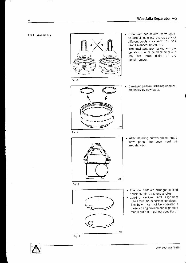
1 .5 . ' 1 Assem b lY . l f the plant has severar ce^:"-Jes,be caref ul not to intercna' :e ca' ls o. fdi f ferent bowls since eac. o3Y/ 1asbeen balanced individua tYThe bowl oarts are marKec w i^ :heserial-number of the macnlne cr w tnthe last three digi ts c ' theserial-number,
Damaged parts must be rePlaced im-mediately by new Parts.
After installing certain critical sparebowl oarts. the bowl must bere-balanced.
The bowl parts are arranged in fixedoosit ions relat ive to one another.Locking devices and al ignmentmarks must be in perfect condit i0n.The bowl must not be operated ifthese locking devices and al ignmentmarks are not in perfect condition.
O O\ /
F ig .4
F ig.
Fig
2044-9001 -201 / 0699

I
rf
ne
1t
i frt
ioo
al ia 5e rator AG
' . 5 . 2 E l e c t r i c a l a p p l i a n c e s
When assembling the bowl. be sureto strictly adhere to the instructionsgiven in chapter "bowl", in order toavoid undue unbalance.Before starting the bowl, be sure to fitall parts.Tighten the bowl lock r ing securely:the "O" marks on the bowl bottom orbowl top and on the lock ring must bein l ine with each other.
Check i f the machine is completelyassembled and properly installed.
Carefully fasten hood 1, feed anddischarge housing 2 and centripetalpump 3 .
The governing accident preventionregulations apply for the electricalappl iances and instal lat ions.The frequency and voltage of thepower supply must correspond to themachine specif icat ions.Carry out potential equalization.Observe legal regulat ions; e.g. inthe EU:- Low-voltage guideline 73l23lEWG- Electro-magnetic compatibility
89/336/EWG
Fig
- 3
Fig. I
o
a
2C44-9001 -201 / 0699
Fig 1 0

(.
1 .5 .3 Be fo re s ta r t ' uP
+ +<!<
F i g . 1 2
F ig . 13
. Check that the bowl icc< '^ j ^as
been f i rmlY t ightened. The 'O" marks on bowl cc : : - c r
bowl toP and on the lock r inE -- -s: oeal igned.
. The bowl must rotate in clockw se dt-rect ion (see arrow on f rarre c ' sol idscol lector).
o The separator may only be operateowith orotection devices conforming toEN 294Eouip sol id and l iquid discharges ac-cordingtY
. Check that the lubr icat ion and coo-ling systems are serviceable.
Fi9 1 4
2a-L1,9oc1-201 / 0699

9 Separator AG
Check whether the supervisoryequipment is operational and the cor-rect limit values are adjusted.When hoods, concentrate collectorsand vessels are pressurized e.g. by- Inert gas,- cool ing,- steam sterilization etc,the pressures stated on the name-plate must not be exceeded.
Check that the product tines are setto ooerat ion.Regularly check hoses for signs ofageing.Check sight glasses for mechanicalu d i l t d u E .
Replaie damaged parts by partswhich are as good as new.
Refer to chapter " opetdtionr ,Note nameplate, The values for- bowl soeed- density of the heavy l iquid,- density of solids (centrifugally dry)are max. values and must not be ex-ceeded.
o Wear ear protection
a
a
Operat ion
Fig
G
Fig. 16
Nameplate
L*fqtio s.pqrsh. AG0-1.?10 0ttfr (\h:t 6rrmony )
Tvp*lesch,-\r ,
[-]o or in *SsuJEha
Tr@1&chrah l 1n D ln- l
Zu ] i i sg lqe 01chte in ko / f i ,@5 SnI?udergutes :
-
$l!:i8u"t, Ef r..t"torr f-l
/ wEsttllJ \gru 'on,
1 -201 / 0699
Fi9 1 8
I'Westfalia Separator AG
F i9. 20
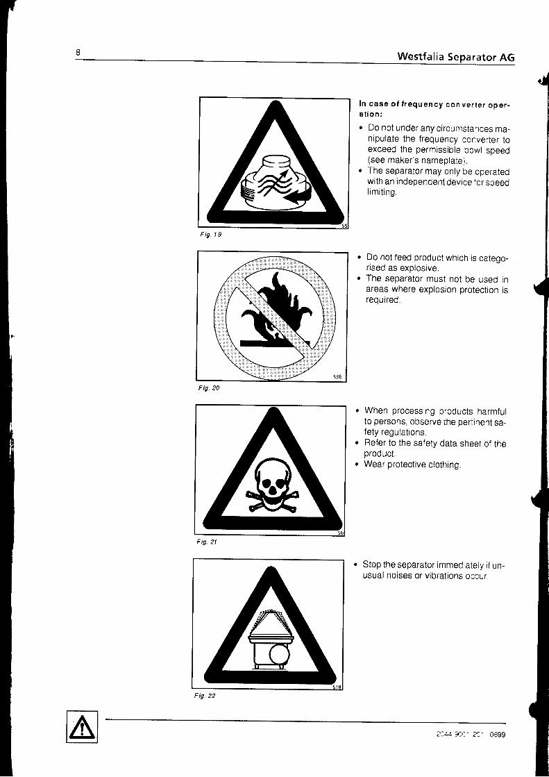
I n case o f l r equ ency con ve r te r ope r -a t i o n :
. Do not under any circumstances ma-nipulate the frequency converter toexceed the permissible bowt speed(see maker 's nameplate)
. The separator may only be operatedwith an independent device f or speedl im i t ing .
Do not feed product which is catego-rised as exolosive.The separator must not be used inareas where explosion protection isreourreo.
When processing products harmfulto persons, observe the pertinent sa-fety regulations.Refer to the safety data sheet of theproduct.Wear protective clothing.
Stop the separator immediately i f un-usual noises or vibrat ions occur.
Fig. 19
gF ig. 21
Fi9
z:4! -!f,- z. 0699
AG
t r -
l d _
toed
^ iw
ed
lo-
rn;^I J
fultA'
ne
)YY
rator AG
Sh u t -d own an d- E m e r g e n c y - O f f u
Fig
m a x . 1 5 m i n
F ig .24
F ig .25
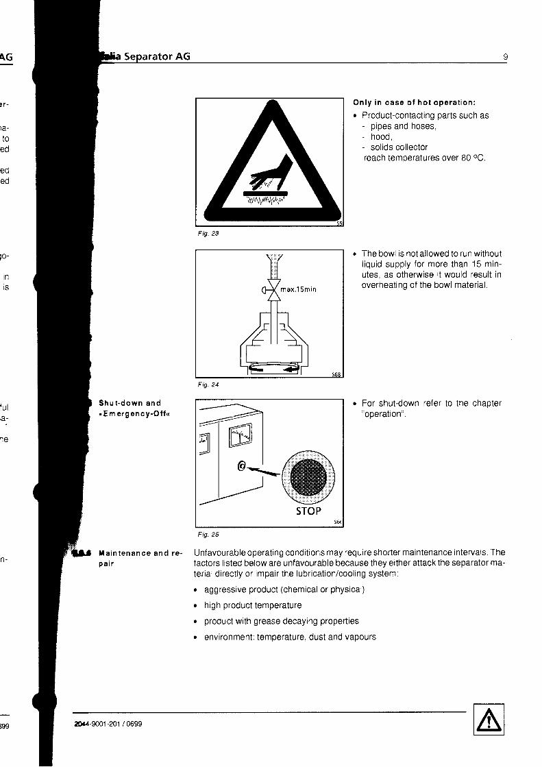
O n l y i n c a s e o f h o t o p e r a t i o n :
o Product-contacting parts such as- pipes and hoses,- hood,- sol ids col lectorreach temperatures over 80 oC.
The bowl is not allowed to run withoutl iquid supply for more than 15 min-utes. as otherwise it would result inoverheating of the bowl material,
For shut-down refer to the chaoter"ooerat ion".
xa in tenance and re . Unfavourab leopera t ingcond i t ionsmayrequ i reshor te rmain tenance in te rva ls .Thep a ir factors listed below are unfavourable because they either attack the separator ma-
terial directly or impair the lubrication/cooling system:
. aggressive product (chemical or physical)
. high product temperature
o product with grease decaying propefties
o environment: temoerature, dust and vaoours
/t-\'|\\VI^\\.1,t,/,'
20.4-9001 -201 / 0699

1 0 Westfal ia Separator AG
Y.
)o
Part icular ly stressed pals s-:- asbearing hub, bowl hub a^: : : -e ' sowlparts with a large outer c a-e:e' -rst
be checked on a regula' cas s : : e^sJresafe and efficient ooerai o-
Before maintenance and servicing,o switch off all electrical appliances via
the main switch,. secure instal lat ion against unin-
tended re-starting with locking de-vices.
D o n o t l o o s e n a n y p a r t b e f o r e t h eb o w l h a s c o m e t o a s t a n d s t i l l .For checking standst i l l re fer tochaoter "bowl .
Fig
Timely maintenance and replacement of worn or damaged machrne parrs s essen-t ial for safe ooeration of the machine.
Maintenance and repair work may only be carried out by the customer to 1r�e extentas described in this instruction manual.
Maintenance and repair work not described in this manual may only be car ed outby the manufacturer or by "repair shops" authorized by the manufacturer
We therefore, recommend in your own interest to have your separator rnscectedby our service engineers at regular intervals. Such inspections wil l keep yo"r separ-ator working rel iable and prevent undesirable shut-downs,
(
Fig
F ig. 28
2044-9001-201 / 0699

\G
1S
wl^ +5 t
(e
Ut
trl
t _
nt
5e rator AG
F ig .29
= --...-<=.-- s6oF i9.
Do not cl imb onto or stand on the ma-chine or parts of the machine.Make provision for and use a sturdyworking platform.
Place dismantled machine oarts on asuitable base, e.g. rubber mat.Take steps to prevent machine partsfrom overturning and rolling away.
Do no t hea t bow l pa r t s w i t h t hen a k e d f l a m e .B o w l p a r t s m u s t n e v e r b e w e l d e d .T h i s a l s o a p p l i e s f o r h o o d a n d s o -l i ds co l l ec to r pa r t s o f s team -s te r i -l i zab le seDara to rs .Even during cleaning the bowl partsthe temperature must not exceed100 "c .
Load-carrying equipment such as lift-ing devices for- bowl or distributor.- chains etc,may only be used for work routinesas described in this instruction man-ua l .Do not use damaged or incompleteload carrying equ ipment.
12044-9001 -201 / 0699

IWestfalia Se rator AG
Collect dr ipping oi l to p.eve^: : a.gerof s l ipping or product r^:e:: c^When handl ing waste o rs ̂ c:e- They can be injur ious tc ̂ ea :^ de-
pend ing on the i r chen :a lom-oosit ion,
- Waste oi l must be d soosec cf rnaccordance with local rec- a: crs.
'-rl
F ig. 33
201'1,/ia' 2c1 , 0699

G
1
; .
a l i a 5 rator AG
Cor ros ion Corrosion can also affect bowl parts made of stainless steel. This corrosion can beflat-spread or pit- or crack-shaped and merits special attention,
Corrosion on stainless steel bowl material should be examined thoroughly and do-cumented.
Flat-spread corrosion can usually be measured (reduction of wall thickness)
Pit- or crack-shaped corrosion cannot be measured without the risk of damage. Atthe ini t ia l stage pi t-shaped corrosion is general ly caused by chlor ine ions.
Depending on the stressing of the part, pit-shaped corrosion can result in crack-shaoed corrosion.
Possible formation of pit-shaped corro-s ron .
Fig. 34
Such pittings can only be investigated by a materials expert,
In case of crack-shaped corrosion aftack with or without superposed flat-spreadand pi t-shaped corrosion on main bowl components, the machine must be shutdown im m ed ia te ly .
Contact your nearest Westfalia Separator AG representative for a thoroug h exami-nat ion.
*:r- -,.) jr-r-t--.rr. - _.tJ--_
-\...' : i - -
---t. ' ;...
Fig.35
Pi t t in gs
Pittings which are close together orform a linear pattern can signify crackformation beneath the surface.Such pittings should be investigated bya materials exDert.
ttr.-9001-201 /0699

r1 A Westfalia Separator AG
1 . 7 E r o s i o n Erosion is caused by solid particles in the process tiquid.These solid particles grind marks into the surfaces with which they come i-:c con-t a u t .
The following factors favour the occurrence of erosion:
. hard solids particles
. high throughput capacit ies
The f i rst s igns of erosion should be careful ly observed and documented. Erosioncan deepen rapidly, thereby weakening the bowl material.
Contact your nearest Westfalia Separator representative for a thorough examrn-ation Information on the nature of the damage can be provided by photos plastercasts or lead molds
The surfaces most susceptible to erosion are
1) the bottom of the distr ibutor. the r is ing channels and the r ibs
2) the centripetal pump (cavitation)
3) all surfaces in the area of the solids discharge ports,
4\ the nozzles.
F ig.
?C.'.,ry-'e' 0699
rator AG
rad ius < 1mm
max. 1mm
F ig .37
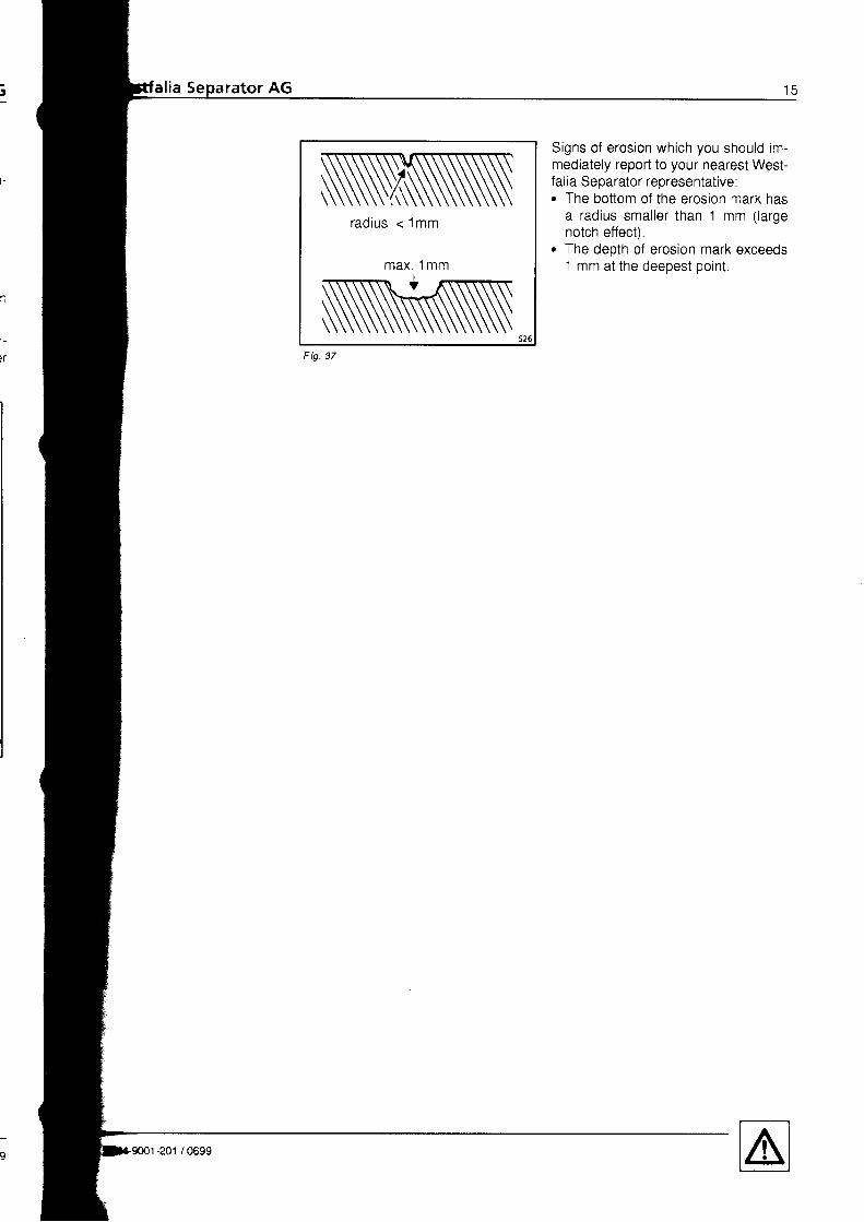
Signs of erosion which you should im-mediately report to your nearest west-falia Separator representative:. The bottom of the erosion mark has
a radius smal ler than 1 mm ( largenotch effect).
o The depth of erosion mark exceeds1 mm at the deepest point

\G
0699
Westfalia Separator AG 1 - 7
g.i.l' : , , : : : : : : : : : :
M ach in .e desc r ip t i on
2 . 12 . 1 . 1
2 . 1 . 2
Appl icat ionCentrifuge with water content monitoring system (WMS) forfuel oil treatmentCentri fuge with sludge space monitoring system (SMS) forfuel oi l t reatment
2.1.3 Centr i fuge with sludge space monitor ing system (SMS) for
z l
22
23
z+
25z o
2828
2.22 , 32 , 42 . 4 . 12 .4 ,22 .4 .32 ,4 .42 . 4 . 52 . 52 . 5 . 1
lube oil treatmentComponents of the plant and the separatorTechnical Data .Operating principles of the separatorOperating principles of the bowlOperat ing pr inciples of the hydraul ical ly control led sl id ing piston . .Operat ing pr inciples of the centr ipetal pumpOperat ing pr inciples of the gearOperat ing pr inciples of the centr i fugal c lutchThe regulat ing r ing .Determining the size of regulating ring by experiment
305 Z
3232e ee e
l -201 / 0699

1 8 Westfal ia Separator AG
\
I
rbx
//-t
l ,
I
234E
678I
1 01 t1 21 41 51 61 71 81 9202'l222324252627293 0
Producl feedShut-off devicePreslrainerGear pumpPre-sel valveSleam-heated oil prehealerAutom. lemperalure regulalorSleam inlclSafely valveLeak oil lo overflow lankCondensate outleiDrain and venl cockFlowmelerPressure gaugeThermomelerCentrifugeNon-relurn valve with shul-off deviccProducl dischargeFeed l ine assemblyOperaling-waler dischargeWatcr dischargcSludge dischargeShul-off device (operaling waler,Pressure gauge (operating wale')Water feedMolor conlrolHoislPressure swilch for clean o crsc.a'gc
S u b j e c t t o m o d i f i c a t i o n !
(
ilN
Fig. 38 - Connectpn diagram of the separator p lanl
2/Y ?:.,-- 2a1 0699

€:qiL::€$
sg 39 - Sect ion ol the sepatator
20441 000{cc
S u b i e c t t o m o d i f i c a t i o n l
99 7;.4-9001-201 /0699
zv Westfal ia Separator AG
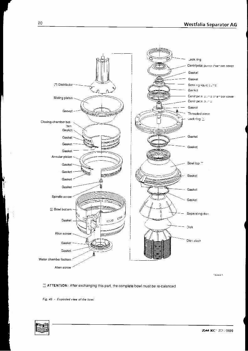
I Distr ibutor
Sliding piston
Gaskel
Closing-chamber bol-lom
Gaskel
Gaskel
Gaskel
Gasket
Annular piston
Gaskel
Gaskel
Gaskel
Gaskel
Spindle screw'
[] Bowl boltom
Gaskel
Allen screw
Gaskel
Gaskel
Lock ring
Cenlr ipetal pump chamber cover
Gaskel
Gasket
Scns rng i qu r c c - - a
Gaskel
Cenlr ipc la o--r : a-cer cover
Cenlr ipc ia o-- ;
Gasket
T h r a : d o r i n r m n
Lock r ing -
Gaskel
Gasket
Gaskel
Gaskel
Gaskel
Separat ing drsk
Disk
D i sk s l ack
Waler chamber bottom /
Allen screw
n ATTENTION: Af ter exchanging th is par t ,
Fig. a0 - Exploded view ol the bowt
the complete bowl must be re-balanced
2u, . ,#. '2a1 , '0699

\G
l r ch ine desc r i bed i n t h i s manua l i s a h igh -speed cen t r i f uga l sepa ra to r w i t h se l f - c l ean ing bow lca l l ed " sepa ra to r " .
ator AG
l g p l i c a t i o n The separators OSC . , -0136-. and OSC . . -s6-, . . wi th UNTTROL systemr are eQuipped with a self-cleaning disk-type bowt and' are applied for clarification and purification in fueloil (up to a density of 1 .0'l g/ml)
and lube oi l t reatment olants.
The centrifuges of the c -Generation are equipped with a "soft-stream-inlet system,,for gentle product treatment. This results in optimum separating efficienly andhi gher specif ic capacit ies,The patented HydroStop system enables controlled bowlejections to be performedat full operating speed, The centrifuges operate without regulating rings,
The centrifuges with uNlrRoL system are provided with two basic monitoring sys-tems:r Water content monitoring system - WMS. Sludge space monitor ing system - SMS
,,separation" means the separation of liquid mixtures which consist of two liquids.with simultaneous removal of the solids contained in the liquids.
, ,Clar i f icat ion" is the removal of sol ids from a l iouid.
The most important component of the centrifuge is the bowl. Depending on the ap-pl icat ion, the bowl of design -0136- can be assembled to ooerateo as clarifier/purifier bowt (WMS) or. as clar i f ier bowlwith sel f- thinker controlsystem (SMS)
Conversion of the clarifier/purifier bowl into a clarifier bowl with self-thinker controlsystem and vice versa can be carried out quickly and easily.
Prerequisite for treatment technology (separation) is that the components of theproduct
- can be separated mechanically- have different densities and- do not emulsify.
2044-9001 -201 / 0699

Westfalia
2 .1 . 1 Cen t r i f uge w i th wa te rc o n t e n t m o n i t o r i n gsys tem (WM S) f o rf u e l o i l t r e a t m e n t
Fig. 41 - W aler content monitoring system (W MS) fot fuel oi! Ireatment
1 Dirty oil feed2 Clean oil discharge3 Displacement water4 Pressure gauge5 Conductivity sensor6 Pressure switch
(no function with WMS)7 Solenoid valve8 Solenoid valveI Sensing l iquid flow
1o Sensing l iqu id pump11 Contro l uni t12 Centr ipeta l pump (c lean o i i )13 Separating disk14 Dirty water discharge15 Sludge space16 Sludge discharge17 Operating water discharge18 Operating water feed20 Contro l holes (openl)
The fuel oi l is conveyed to the centr i fuge by means of a separate pump or a pumpflanged to the separator,
The clar i f ied clean oi l is discharged under pressure (2) by means of centr ipetalp u m p ( 1 2 ) .
The bowl is opened and closed automaiically for solids ejection at f ull bowl speedby means of a remote-control led solenoid valve in the operat ing water l ine. Theopening t ime of the solenoid valve is 3 seconds.
The smal lvolume of l iquid (9)which is branched off v ia the separat ing disk (13) andthe sensing l iquid pump (10) is monitored by a conduct iv i ty sensor (5)lf the sensor registers water the solenoid valve (8) opens and the water ftows offthrough the dir ty water discharge (14). The centr i fuge operates as a puri f ier.As soon as the sensor detects a change in conduct iv i ty brought abcut by an in-creased proport ion of oi l , the solenoid valve (8) closes and the solenoid valve (7)opens intermit tent ly. The sensing l iquid f low (9) is recycled rnto t : re feed (1). Thecentrifuge operates as a clarifier.
The control and monitor ing unit guarantees unsupervised opera: icn
2CL4 ?i.'a' 201 /0699
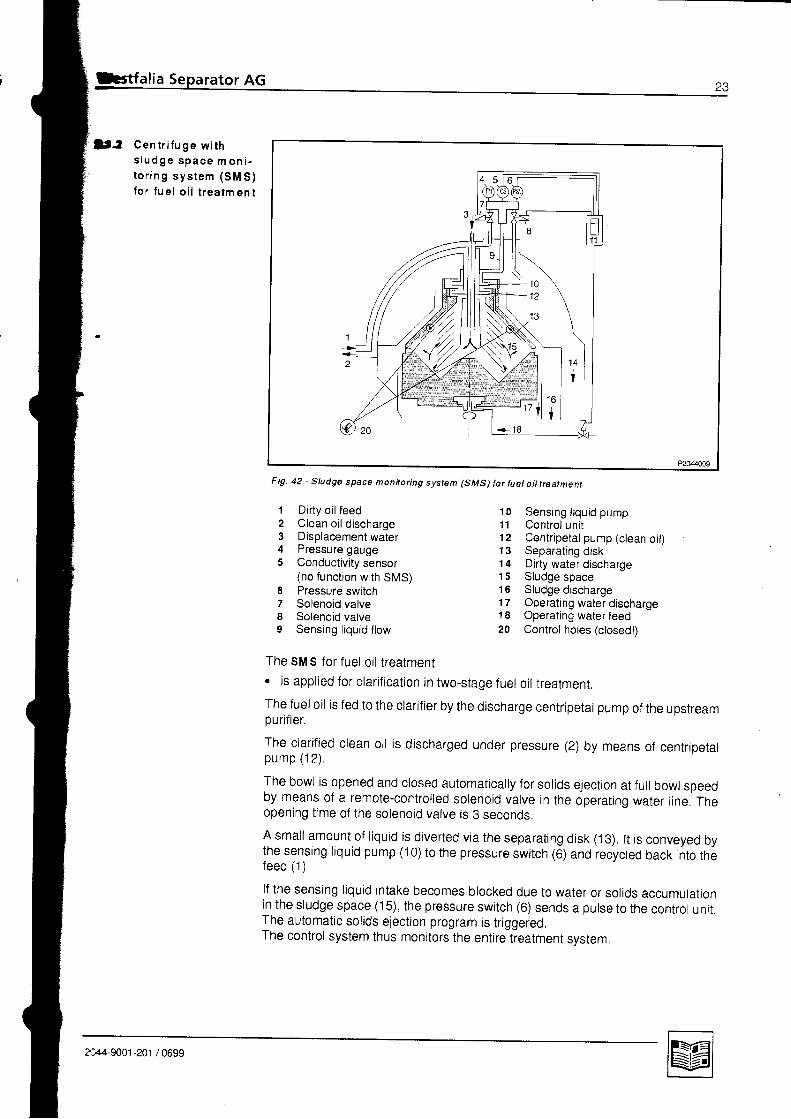
l f : Cen t r i f u ge w i ths t u d g e s p a c e m o n i -t o n n g s y s t e m ( S M S )lo r l ue l o i l t r ea tm en t
Fig. 42 - Sludge space monitoring system (SMS) lor fuet oiltreatment
12345
Dirty oil feedClean oil dischargeDisplacement waterPressure gaugeConductivity sensor(no function with SMS)Pressure switchSolenoid valveSolenoid valveSensing l iquid flow
10 Sensing l iqu id pump11 Contro l uni t12 Centripetal pump (clean oil)13 Separating disk14 Dirty water discharge15 Sludge space16 Sludge discharge17 Operating water discharge18 Operating water feed20 Control holes (closed!)
78o
The sM s for f uel oil treatment. is applied for clarification in two-stage fuel oil treatment.
The fuel oil is fed to the ctarifier by the discharge centripetat pump of the upstreampurifier.
The clarified clean oil is discharged under pressure (2) by means of centripetalp u m p ( 1 2 ) .
The bowl is opened and closed automatically for solids ejection at full bowl speedby means of a remote-controlled solenoid valve in the operating water line. Theopening time of the solenoid valve is 3 seconds.
A small amount of tiquid is diverted via the separating disk (13). tt is conveyed bythe sensing liquid pump (i 0) to the pressure switch (6) and recycted back into thefeed {1 ) .
lf the sensing liquid intake becomes blocked due to water or solids accumulationin the sludge space (15), the pressure switch (6) sends a pulse to the controt unit.The automatic solids ejection program is triggered.The control system thus monitors the entire treatment svstem.
?71-s061 -rot , ornn
24 Westfalia Separator AG
2 .1 . 3 Cen t r i f uge w i ths l u d g e s p a c e m o n i -t o r i n g s y s t e m ( S M S )f o r l u b e o i l t r e a t m e n t
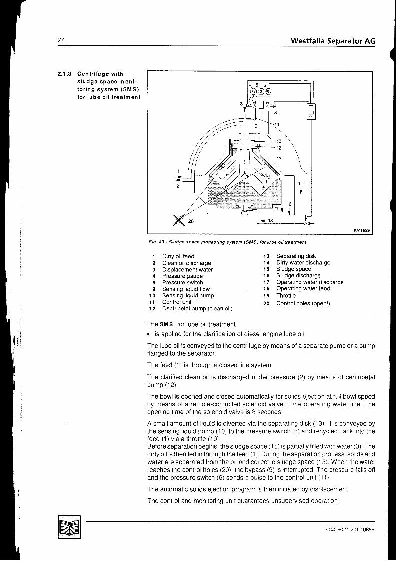
Fig. 43 - Sludge space monnoilng system (SMS) for lube oil trcatmenl
1 Dirty oil feed2 Clean oil discharge3 Displacement water4 Pressure gauge6 Pressure switch9 Sensing l iquid flow
10 Sensing l iqu id pump11 Contro l uni t12 Centripetal pump (clean oil)
13 Separating disk'l4 Dirty water discharge15 Sludge space15 Sludge discharge17 Operating water discharge18 Operating water feed19 Throttle20 Control holes (open!)
The sMs for lube oi l t reatment. is appl ied for the clar i f icat ion of diesel engine lube oi l
The lube oil rs conveyed to the centrifuge by means of a separate pump or a pumpflanged to the separator.
The feed (1) is through a closed l ine system.
The clarified clean oil is discharged under pressure (2) by means of centripetalp u m p ( 1 2 ) .
The bowl is opened and closed automatically for solids ejection at f ull bowl speedby means of a remote-control led solenoid valve in the operat ing water l ine. Theopening t ime of the solenoid valve is 3 seconds
Asmal lamounto f l iqu id i sd iver ted v ia thesepara t ing d isk (13) l t i s conveyed bythe sensing l iquid pump (10) to the pressure switch (6) and recycled back into thefeed (1) via a thrott le (19).Before separat ion begins, the sludge space (1 5) is part ial ly f i l led with water (3). Thed i r ty0 i l i s thenfed in th roughthe feed(1) Dur ing thesepara t ionprocess so l idsandwater are separated from the 0i l and col lect in sludge space (1 5) Wnen the waterreaches the control holes (20) the bypass (9) is interrupted. The pressure fal ls of fand the pressure switch (6) sends a pulse to the control uni t ( l1 l
The automatic sol ids eject ion program is then ini t iated by displacement
The control and monitor in0 unit ouarantees unsuoervised ooera:ror
nzA 3Ca. 201 /0699

Westfalia Separator AG
\
2 .3 Techn i ca l Da ta S u b j e c t t o m o d i f i c a t i o n !
C e n t r i p e t a l p u m p
Delivery capacity 15 000 - 23 000 l /h
Pressure head 2 - 3 b a r
Standa rd ope ra t i ng wa te r spec i f i ca t i on
Vol. of susoended matter max. 10 mg/ l
Part ic le size max, 50 pm
Hardness:
- up to 55 oC separating temperature- above 55 oC separating temperature
< 1 2 0 d H
< 6 0 d H
The different hardness specifications can be converted using the formula glven be-low:1 " d H = 1 . 7 9 " f H = 1 . 2 5 " e H = 1 7 9 p p m C a C O 3
Chlor ine ions < 100 mg/l
pH value 6 . 5 - 7 . 5
M o to r
Power 1 5 - 2 2 k W
Speed at 50 Hz , 1 t r t r r n ma J J r v t t l
Speed at 60 Hz 1 745 rpm
Design B 5
B o w l
Solids space (total) 1 1 d m 3
Speed for densities- of the product up to 1.05 kg/dm3
(at 15 oC) and- the separated sol ids up to 1.4 kg/dm3
6 440-6 550 rpm
Speed for higher densit ies consult the factory
Starting time 6 - 1 0 m i n
?;:-1 T:' 201 /0699

I
AG
0 -
!
I
naoo
rator AG
F e e d p u m p
Flanged gear pump or alternatively pump unit(gear or screw pump)
Pump output(rating according to plant possible)
4 500 - 25 000 yh
Suct ion height 4 m W C
Pressure head. adiustable 1 0 - 2 0 m W C
W e i g h t s
separator (without motor, without pump) 1 220 kg
Bowl 365 kg
3-phase AC motor 140 kg
DC motor 243 kg
Gear pump (depending on s ize) 1 1-46 Kg
Pre-strainer (depending on pump output) 8 - 2 6 k g
C ap aci ty
The capacity of the separator depends on the. viscosity. temperature. density. impuri ty loading. water content and. required degree 0f purity of the product

z6 Westfalia Separator AG
2 . 4 O p e r a t i n g p r i n c i p l e s o ft h e s e o a r a t o r
2.4 .1 Opera t ing pr inc ip leso f t h e b o w l
G en e ra l
A separator is characterized by the bowl for a specific applicati0n. Before comingto the particulars of the bowl the general operating principles of the separator areexolained first
Liouid mixtures or liouid-solids mixtures can be seoarated- in the gravitational field of the settling tank or- in the centrifugal field of the separator,
orovided the constituents of the products have different densities.
As the centrif ugal field of the separator is extremely more effective than the gravita-tionalfield of the settling tank. centrifugal separation in the separator is much fasterthan separation in the settling tank.
d l s c h a r g i n g c l a r i f l e d l l q u i d
sed im en t
f ttny R- (D,I n c o m i n g d l r t y l i q u i d
F ig .44
P u r i f i e r b o w l
A l iquid mixture of l ight and heavy phases, e.g. oi l - water, iS separated into i ts c0n-stituents in the disc stack of the purifier bowl.
The disc stack consists of a large number of conical discs placed one above theother. Each disc is provided with Spacers which ensure precisely determined nar-row disc interspaces.
The entire separation chamber therefore consists of many parallelly arranged inter-spaces of low height, thus reducing the radial sett l ing distance for the sol tds.
The sol idso settle on the underside of the disc above and
. sl ide down into the sol ids holding space.The smooth disc surfaces favour sl id ing down of the sol ids and ̂ en ce sel f-c lean-ing of the discs.
M n:1 ,201 /0699

The constituents of the liquid mixture (light and heavy phases) are separated in theseparation chamber.
C lar i f ie r bowl
The clarifier bowl is used if solids are to be separated out of a liquid.The operating principle of the clarifier bowl only differs from the purifier bowl in that. the discharge of the heavy liquid phase is ctosed.
Only sol id- l iquid separat ion takes ptace.
2044-9001 -201 / 0699

rator AG
2 . 4 . 2 O p e r a t i n g p r i n c i P l e so f t h e h y d r a u l i c a l l yc o n t r o l l e d s l i d i n gp i s t o n
5
7
2 +1 +
i11
Separa t i on
B o w l c l o s e d
E i ec t i onB o w l o p e n
Fig. 45 - The self-cleaning bowl
1 Light component discharge(centripetal pumP)
z Product feed3 Feed for make-uP water4 Sludge space5 solids discharge (bowl)s Sliding piston7 Annular piston
a Closing l iquid discharges Opening l iquid discharge
1o Heavy component discharge11 Solids discharge12 Operating l iquid feed13 Injection chamber14 Operating l iquid discharge
1i,li{ l
l l llrl
The operating liquid (usually water) fed into the rotating bowl produces a high cen-tr i fugal pressure. This pressure is ut i l ized to actuate the annular piston and sl id ingpiston which open and close the bowl.
The sl id ing piston and annular piston
are. as shown in the figure. inside the bowl bottom
rotate with the same angular velocity as the other bowl parts
are axiallv movable.
a
a
a
n4 na', 201 / 0699

\G
I ng
ator AG
C l o s i n g t h e b o w l
After starting the separator, the shut-off device for operating liquid is actuated bymeans of the control uni t .
The operat ing l iquidr flows into the injection chamber of the bowl bottom and. from there through inlet holes into the closing chamber.
By this means closing of the bowl is initiated.
The annular piston. moves into closed position.
The l iquid pressure in the closing chamber. r ises the sl id ing piston,r presses the sliding piston against the gasket of the bowl bottom, thus
. c losing the bowl.
O p e n i n g t h e b o w l ( e j e c t i o n )
The shut-off device for operating liquid is opened by means of the control unit
The operat ing l iquid. flows first into the ejection chamber and. then into the opening chamber.
The annular piston
o rises thus causing. emptying of the closing chamber.
The sl iding piston. moves downwards and. opens the ejection pofis in the bowl bottom for discharging the separated solids
2044-9001 -201 / 0699

sz Westfalia Separator AG
2.4.3 operat ing pr inciples The centr ipetal pump discharges the separated l iquid under pressure.of the centr ipetal The operat ing pr inciples of the centr ipetal pump can be compared with that of apump cent r i fuga l pump.
In case of the centrifugal pumpr the impeller fitted with inclined vanes rotates in a stationary casing;. the l iqu id tobepumpedf lowsf romthe ins ide to theouts ide through impe l le rvane
cnannels.
r/
I
Fig-
The reverse is the case with the cen-tr ipetal pump:o it is fixed to the hood of the separator;r its disc, which is provided with chan-
nels, is immersed in the liquid rotat-ing with the bowl.
2 . 4 . 4 O p e r a t i n g p r i n c i p l e so f t he gea r
2 . 4 . 5 O p e r a t i n g p r i n c i p l e so f t h e c e n t r i f u g a lc l u t c h
The liquid is peeled off by the centripetal pump and flows into its spirat channetsfrom outside, its kinetic energy being converted into pressure energy which is ca-pable of discharging the l iquid under pressure.
At a low backpressure the depth of immersion of the centr ipetal pump is smal l , l tcan, however, be increased by throttling the valve in the discharge tine. By thismeans it is oossible to obtain
- a good l iquid seal,- an air- and foamfree product,- a higher backpressure.
The separator is driven by a standard motor, type 85.Power transmission to the bowl spindle is effected via a centrifugal clutch to theworm wheel shaft and from there via a worm gear where the worm wheel is the driv-ing member and the worm the dr iven member. Simultaneously the mounted gearpump is driven by the worm wheel shaft via a safety clutch
The centrifugal clutchr gradual ly br ings the bowlto i ts rated speed. eliminating premature wear on gear parts and on the motor,
The start ing current and the accelerat ion t ime can be regulated by the number ofclutch shoes inserted.
For further details refer to sect. 4.6 - Centrifugal clutch.
2044-9001 -201 / 0699
Westfalia Separator AG J J
2 . 5 T h e r e g u l a t i n g r i n g(using oil purif icationas an exampte)
2 . 5 . 1 D e t e r m i n i n g t h e s i z eo f r e g u l a t i n g r i n g b yexp e r i m en t(using oil purif ication asan example)
Only fo r -02- opera t ion
F u n c t i o n o f t h e r e g u l a t i n g r i n g
Optimum dewatering of oils containing water is only possible if the bowl is correctlyadjusted to the difference in density between the oil and the water.
The regulat ing r ing with the correct inner diameter, i .e. with the diameter that corre-sponds to the density difference between the oil and water, should therefore be se-lected from the set of regulating rings (with different inner diameters) supplied withthe separator and fitted in the bowl.
The inner diameter of the regulating ring to be selected can be determined by ex-oeriment. The rule of thumb is:r smal l regu la t ing r ing fo r heavy o i l ,r la rge regu la t ing r ing fo r l igh t o i l .
To avoid emulsification, begin the test by inserting a large diameter regulating ringand then switch t0 the next smallest.
l f the regulat ing r ing is too large,- the water discharging through the water outlet will contain oil.
l f the regulat ing r ing is too sm al l ,- s l ight emulsi f icat ion wi l l occur or- the 0il discharging through the clean oil outlet will contain water,
The milky or dirty appearance of the water is quite normal: it is caused by the oilwasnrng process.
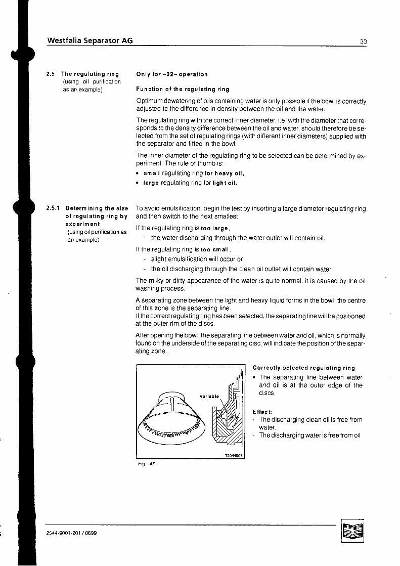
A separating zone between the light and heavy liquid forms in the bowl; the centreof this zone is the separat ing l ine.lf the correct regulating ring has been selected, the separating line will be positionedat the outer rim of the discs.
After opening the bowl, the separating line between water and oil. which is normallyfound on the underside of the separating disc, will indicate the position of the separ-at ing zone.
Cor rec t ly se lec ted regu la t ing r ing. The separating line between water
and oil is at the outer edge of the0lscs,
E ffec t:- The discharging clean oi l is f ree from
waIer.- The discharging water is free from oil,
214-900t-201 / 0699

t o o w i d e
u
t oo na r row
Inner d iam e ter o f regu la t ing r ing toow i d er The separating line between water
and oi l- is located far outside 0f the discs
and- is too close to the outer rim of the
separat ing disc.
E ffec t:- The discharging clean oi l is f ree from
waIer.- The discharging water contains oi l or- oil breaks the water seal.
Inner d iam e ter o f regu la l ing r ing toon ar rowo The separat ing l ine between the
liquid components is located towardsthe smal l diameter of the discs in-stead of being at the outer rim of the0rscs.
E ffec t:- The discharging clean oi l contains
water.- The discharging water is f ree from oi l .
2044-9001-201 /0699

festfalia Se rator AG
' : . : : : . : . : : r r ' : . . . . . .
3 . Opetat ion
e l l
3 . 1 . 2e t e
3 . 1 . 4e l t r
J . Z
3 . 2 . 13 .2 .2
3 . 4a t r" R l
383838
404 14 1+z
Technical informationSeoarationNotes on separation with the purifier bowl (-02- operation) . . . . .Make-uo water ,Notes on separation with the clarifier bowlGeneral information on bowleiect ions . . .Before start-uoBefore initial start-upWhenever startingStart-up of separator .Monitoring of operationSetting the separating tiDetermining the separaB o w l e i e c t i o n s . . . . . .
3.7 Stopping the separator3.8 Trouble shooting3,8.1 Separator faults .3.8.2 Bowlfaults
; " , . . . . :t ing t ime by calculat ion . . , .
5 l
37
Z+J
444448
2044-9001-201 /0699
Westfalia Separator AG
T e c h n i c a l i n f o r m a t i o n
S e D a r a t i o n
3 .1 . 2 No tes on sepa ra t i onw i t h t h e p u r i f i e r b o w l( -02 - ope ra t i on )
3 .1 . 3 M ake -u p wa te r
Take note of the following sections:
The best separation efficiency is achieved with lowest viscosity of the product tobe seoarated.In the case of non-conforming products,
- refer to the sales documents or- consult the manufacturer.
In the case of emulsified oil the separating temperature must be increased.
lf an oil pre-heater is used, a temperature controller (thermostat) must befitted. Thetemperature of the feed product must be displayed on a screwed-in thermometer.
The centr i fuge- can be converted into a purifier without self-thinker control system with the aid
of a conversion kit (see sect. 2.5)- and can then be applied in the first separation stage.
The operating mode of the control unit must be switched to "Separation" so that thebowl is supplied with the sealing water necessary for purifiers. The water seal whichprevents the oil from discharging through the water outlet must be maintained dur-ing separatron.
(
Lube oil seoaration Make-up water. i.e. ior instance the dropwiseaddition of water throughput the entire separat-ing t ime.This practice was commonplace in the past;however with today's high detergent oi ls (HD =H eavy D uty) it is now the exception and shouldonly be carr ied out after consult ing the oi l manu-facturer.
Heavy fuel oil separation Make-up water, i .e. for instance the cont inuousaddit ion of wash water up to 10 % by vol .This is accepted practice in fuel treatment foronshore power plants with gas turbines.
2044-9001 -201 / 0699

I o t e s o n s e P a r a t i o nr r t h t he c l a r i l i e r bow l
G c n e r a l i n f o r m a t i o non bow l e iec t i ons
The centrifugal clarifier is equipped with the self-thinker control System as a stan-dard feature.
The clarifier bowl may not be supplied wrth water (exception: checking the self-
thinker funct ion and during displacement),The operating mode "Clarifying" must therefore be switched on the control unit. This
automatical ly suppresses the f i l l ing process.
The clarifier bowl with self-thinker control system serves to polish the products in
the second separation stage while at the same time executing a monitoring f unction
and solids-dependent solids ejection control of the entire system.The centrifuge therefore carries out a quality check of the different products.
The bowl is ejected at full bowl speed by automatic actuation of the solenoid valves
for operating water.
In the clarifier operating mode with self-thinker control system the ejection time iS
determined by the level of solids in the bowl
lf the centrifuge is operated as a conventional purifier, the ejection time must be
determined by calculation or graphically (see 3.5). The determined separating timeparameter must be set on the control unit.
D i s p l a c e m e n t
When separating, the loss of feed liquid unavoidable during ejection. can be re-
duced to a minimum by displacing the feed liquid with water before sludge ejec-
tion takes place This is of special importance when processing valuable feed
l iqu id .
The duration of the displacement liquid supply has to be determined by experi-
ment.
. l f the t tme of displacement is too long, displacement l iquid wi l l d ischarge from
the l ight l iquid out let
o l f the t ime of displacement is too short , part of the valuable feed l iquid wi l l re-
main in the bowl and then be ejected during ejection.
r Disptacement of the light liquid can also be accomplished by throttling the valve
in the discharge l ine for heavy l iquid.
F lu sh e jec t ion
lf the solids are firmly stuck to the wall and cannot be ejected- due to an excessively long dwell time or- due to the solids Properties,
either the separating time must be shortened or a f lush ejection must be carried out
after a total ejection by fil l ing the bowl with water or product, and emptying it again
P r o g r a m c o n t r o l
. Displacement, ejection and flush ejections at precisely defined intervals are best
carried out with the automatic control unit.
o The clean oil discharge and water discharge can be monitored'
o Faults can be signalled optically or acoustically.
2044-9001 -201 / 0699

sa Westfalia Separator AG
3 .2 Be fo re s ta r t -up
\
3 .2 .1 Be fo re i n i t i a ls tar t -u P .
a
N ote:- Safety precautions in section 1 .- Instruction manual of the resoective control unit
Check hoses and hose pipes (3.4).
Fi l l gear chamber with oi l through oi l f i l l hole unt i l o i l levet is up to upper third ofsight glass (4 2.2).
Fi l l some oi l into oi l suct ion pipe of gear pump ( i f avai lable) to prevent the pumpfrom seizing.
Check height of bowl and centr ipetal pump: see sect ion 4.5.
Release brake by turning handle clockwise.
Check if bowl can be turned by hand.
Close the hood and fasten with hex head screws.
Apply a thin film to guide surfaces and threads of handte connection piece (seelubrication chart)
. Introduce handle connect ion oieceinto hood and screw it down to fastenthe centr ipetal pump (tef t-handth read ).To do this, use wrench 2.
. Connect water supply l ine.
Loosen brake by turning the handle clockwise.
Check if bowl can be turned by hand.
Close the hood and fasten with hex head screws,
Apply a thin f i lm to guide surfaces and threads of handle connect ion piece (seelubricat ion chart) .
. Introduce handle connect ion pieceinto hood and screw it down to fastencentr ipetal pump ( lef t-h an d th read ).To do this, use wrench 2.
o Connect ion water supply l ine.. Check i f gear chamber is f i l led with oi l
up to upper third of s ight glass.
a
a
3 .2 .2 Wh en eve r s ta r t i n g
2044-9001 -201 / 0699
Westfalia Separator AG 39
! . 3 S ta r t -up o f sepa ra to r I
a
See section 3.2.2.
On separa tor w i th f langed gear pump:- Open shut-off device in the dirty oil l ine.
Switch on the motor.
Compare current and start ing t ime with the diagram (sect. 4.1.3) unt i l the bowlhas reached the speed specified on the separator nameplate (revolution indica-tor) after approx. 6 - 10 minutes.
O n p u r i f i e r :- Start the oil pre-heater after switching on the motor!
Hydraulically close the bowl:- Briefly open the shut-off device for operating liquid several times,
Open the shut-off valve in the clean oil discharge.
Switch on the control uni t .
Start the program.
After the feed valves have automatically opened- set the clean oil backpressure to approx. 2.0 bar',- adjust the desired throughput;- correct the backpressure in the clean oil discharge if necessary.
Check discharges for s ludge and dir ty water; there must be no oi l f low!
Check backpressure in self-think-er system. This should be 1.6 - 1 .9 bar.
a
a
a
a
a
a
2044-9001-201 /0699

40 Westfalia Separator AG
a l t e r f o l l o w i n g o p e r a t i n g h o u r s
O P E R A T I O N S
at th e la tes t every
7 5 0 1 5 0 0 4 0 0 0 8 0 0 0 1 6 0 0 03
m on ths
6
m o n l n s
,|y a a t
2y r a r s
L U B R I C A T I O N
o First oil change after init ial start-up. r! oweek l y Check oi l level week l y
o W h e n u s i n g m i n e r a l o i l : f l
Oi l change and thorough cleaning of gear chamber. tr o
o W h e n u s i n g s y n t h e t i c o i l : @
Oil change and thorough cleaning of gear chamber. tr ow h e n e v e r d l s m a n t l l n g Grease sliding and guide surfaces of main bowl parts. E o
o Remove. clean and greasetr the bowl lock ring, and re-in-stall i t. o
On your dai ly round - especial ly dur ing the f i rst '1500 operat ing hours - pay attent ion to the fol lowing:
. Oi l level
. Temperatureso Pressuresr Leakageso Vibrationso Power consumption. Start ing t ime
,l3 . 4 M o n i t o r i n g o f o p e r a t i o n
H o s e s a n d h o s e p i p e s
Service lifeincluding slorage lime if applicable
6 years
Storage l i fe 2 years
Replace the hose pipes if any of the fol lowing criteria are established during inspection:
. Damage to the outer layer extending through to the texti le layer (e.9. rub marks, cuts or cracks)
. LeaKS.
. Damaged or deformed hose f i t t ing ( impaired seal ing funct ion).(S ight surface damage is no reason for replacement )
o The hose becomes dislodged from i ts f i t t ing.
. Corrosion of the f i t t ing which impairs funct ion and strength,
Whenever changing oi l , clean gear chamber thoroughly.see secl ion 4.2.2 - oi l qual i tyscc sccl ion 4.2.3 - lubrication chartWe recommend the synthel ic grease Mobil i th SHC 100 or SHC 460 for greasing this part; i i has given gocd rcsul is tn practice.
K e y :
m *r -
2044-9001-201 / 0699
a l i a S rator AG
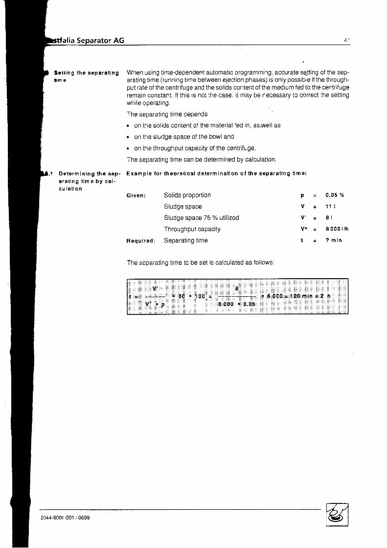
Sc t t i ng t he sepa ra t i ngD m e
D e t e r m i n i n g t h e s e p -a r a t i n g t i m e b y c a l -c u l a t i o n
When using time-dependent automatic programming, accurate se.tting of the sep-arat ing t ime (running t ime between eject ion phases) is only possible i f the through-put rate of the centrifuge and the solids content of the medium fed to the centrif ugeremain constant. lf this is not the case. it may be necessary to correct the settingwhi le operat ing.
The separat ing t ime depends
. on the solids content of the material fed in, as,well as
. on the sludge space of the bowl and
o on the throughput capacity of the centrifuge.
The separating time can be determined by calculation.
Exam p le fo r theore t ica l de term ina t ion o f the separa t ing t im e :
G i ven : Solids proport ion
Sludge space
Sludge space 75 % utilized
Throughput capacity
Regui red: Separat ingt ime
The separating time to be set is calculated as follows:
p =
V =
V ' =
V o =
t =
0 . 0 5 %
1 1 |
8 l
8 0 0 0 l / h
? m i n
Iv:t = . 5 0 . 1 0 0 = - - - - - J - - - - - r $ 0 0 0 = 1 2 0 m i n = 2 h
V " . p 8 0 0 0 . 0 , 0 5
2044-9001-201 /0699
+z Westfalia Separator AG
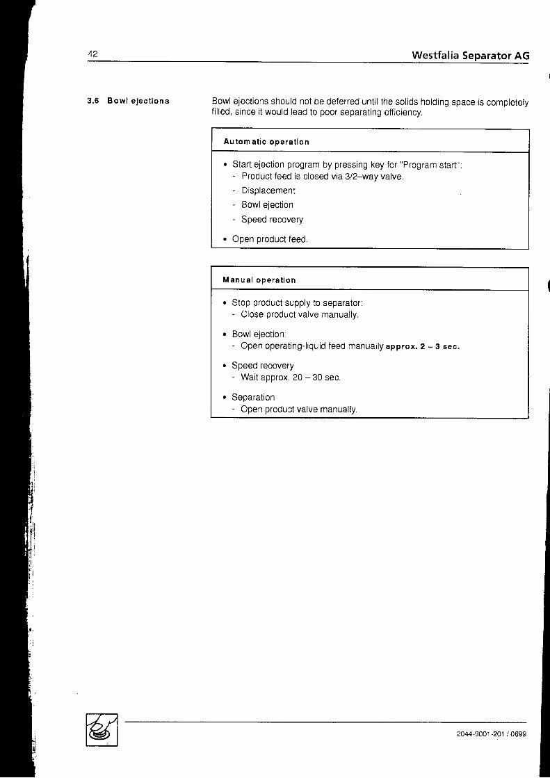
3 . 6 B o w l e j e c t i o n s Bowl ejections should not be deferred until the solids hotding space is completelyfilled, since it would lead to poor separating efficiency.
Au tom a t i c oDera t i on
. Start ejection program by pressing key for "Program start":- Product feed is closed via 312-way valve.- Displacement- Bowlejection- Speed recovery
. Open product feed.
M a n u a l o p e r a t i o n
. Stop product supply to separator:- Close product valve manually.
e Bowl eiect ion:- Open operating-l iquid feed manually approx. 2 - 3 sec.
. Speed recovery- Wait approx. 20 - 30 sec.
. Separation- Open product valve manually.
2044-9001 -201 / 0699

. E & g p r n g t h e
rator AG
separator . Switch off the preheater.- Continue to feed product for a few minutes, since the preheater continues to
heat for a short time.
Au tom a t i c ope ra t i o n
. Displacement
. Start ejection program by operating key for "Program start":- the ejection program runs down.
o After ejection stop the separating program by operating key for "Program
stoD",
M a n u a l o p e r a t i o n
Close the oroduct feed:- Close product valve manually.
Perform sol ids eiect ion: s. sect ion 3.6
Close discharge of l ight l iquid (oi l ) .
Close feed for operating water. fil l ing and displacement water.
Switch off the motor.
Switch off the feed pump
Close shut-off device in suction side of feed pump.
Brake the seoarator.
Apply brake by turning handle ant i-c lockwise,Wait until the bowl has come to rest!
D o n o t l o o s e n a n y p a r t b e l o r e t h e b o w l i s a t a s t a n d s t i l l .
Only when the revolution indicator disc has stopped rotating is the bowl at rest!
-J a
a
a
2044-9001 -201 / 0699
44 Westfalia Separator AG
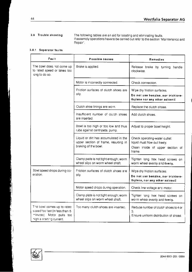
3 . 8 T r o u b l e s h o o t i n g The fol lowing tables are an aid for locat ing and el iminat ing faul ts.lf assembly operations have to be carried out refer to the section "Maintenance andReoair" .
3 .8 .1 Sepa ra to r f au l t s
F a u l t P o s s i b l e c a u s e s R e m e d i e s
The bowl does not come uoto rated speed or takes toolong to do so
Brake is aool ied. Release brake by turning handleclockwise.
Motor is incorrectly connected Check connection.
Friction surfaces of clutch shoes areorly.
Wipe dry friction surfaces.
D o n o t u s e b e n z i n e , n o r t r i c h l o r e -l h y l e n e n o r a n y o t h e r s o l v e n t !
Clutch shoe l in ings are worn. Reolace the clutch shoes.
Insufficient number of clutch shoesare inserted.
Add clutch shoes.
Bowl is too high or too low and thusrubs against centripetal pump.
Adjust to proper bowl height.
Liquid or dirt has accumulated in theupper section of frame. resulting inbraking of the bowl.
Check operating-water outlet:liquid must flow out freely.
Clean inside of upper sect ion o{frame.
Clamp plate is not t ight enough; wormwheel slios on worm wheel shaft.
Tighten long hex head screws onworm wheel evenly and firm ty.
Bowl speed drops during op-eratron.
Friction surfaces of clutch shoes areorly.
Wipe dry friction surfaces.D o n o t u s e b e n z i n e , n o r t r i c h l o r e -thy lene , no r any o the r so l ven t !
Motor speed drops during operation, Check line voltage and motor.
Clamp plate is not t ight enough; wormwheel slios on worm wheel shaft,
Tighten long hex head screws onworm wheel evenly and f i rm ly.
The bowl comes up to ratedspeed too fast (in less than 5minutes) Motor pul ls toohigh a start ing current.
Too manv clutch shoes are inserted, Reduce number of clutch shoes to 4 or
Ensure uniform distr ibut ion of shoes
2044-9001 -201 / 0699

P o s s i b l e c a u s e s R e m e d i e s
,^even run of seoarator. Bowl is out of balance due to followinouct u5u5.
1. The separated solids have deoos-ited unevenly in the bowl.
2. The bowl is incorrecfly assembled0r parts of different bowls (if ptanthas several separators) have beeninterchanged.
3. The pressure in the disc stack hasslackened.
4, Bowl parts are damaged.
P o s . 1 - 4 :
. Stop separator.
. Apply brake.
. Close dirty oil feed and clean oildischarge.
o B o w l e j e c t i o n m u s t b e a v o i d e d ,since otherwise the vibrations oc-curing during slowing down wouldIncrease.
lf the bowl leaks,. open water supply all the way.
Assemble bowl correctrv
Check if bowl lockring is screwed ontightly.
An insu f f i c i en t l y t i gh tened l ockr i ng can m ean dange r t o l i f e !
Check number of discs.
Send bowl to factory for repair.Do not attempt to make your own re-pairs!
Never we ld o r so lder s ince i t wou ldimpair the strength of the bowil
Neck bearing spr ings are fat igued orbroken.
Replace al l neck bearing spr ings.
Cup springs or cylindrical pressurespring in bottom bearing are broken.
Insert new cup springs or cyl indricalpressure spflng.
Bowl is too low in the frame. Readjust bowl height.
Bal l bearings are worn, Replace worn bearings.ATTENTION!As spindle bearings use only high p recision bal l bearings (see l ist of pa' :s
2044-9001 -201 / 0699

46 Westfalia Separator AG
F a u l t P o s s i b l e c a u s e s R em ed ies
uneven(cont 'd.)
run of separator Gear parts are in bad condition due to
1. normal wear.
z . premature wear caused by:
a) lack of oil E
b) oil of too low a viscosity tr
c) metal abrasives in the lube oilbecause- viscosity of oi l too low- oi l has not been changed in
t tme,- gear chamber has not been
cleaned.
d) gear parts have not beenchanged at the same t ime.
e) Water infiltration. because
operat ing- l iquid shut-off de-vice was open for a longer pe-riod during standstill of sepa-rator.
Clean gear chamber thoroughly.
Replace entireworm wheel and, atthesame time, worm spindle (never re-place only one gear part).Be sure to refer to sect. "Fitting theworm wheel and worm wheelshaft"!
Fi l l in fresh oi l .Change oi l more often.
In case o f water in f i l t ra t ion :Operating-water data:- Pressure2-5bar- Volume min. 3 000 l /h (gauge ca-
pacity by l i t res) + 1.6 | in 2 sec
Shut-off device must always remainclosed during standstill of separator,lf necessary, secure it with a secondshut-off device.
I normally recognizable by blue lemperingcolour of gear parls.
2044-9001-201 /0699

F a u l t P o s s i b l e c a u s e s Rem ed ies
Feec pump does not sucK tn{ f ava r l ab le ) .
Feed pump does not function cor-rectly.
Check sealing r ing in pump.Check excess pressure valvelf necessary, readjust it.
Suction lines are blocked or leakv. Clean or seal suct ion l ines,Check foot valvel
Prestrainer is blocked or leakv, Clean prestrainer.Replace gasket in housing cover.
2044-9001 -201 / 0699
48 Westfalia Separator AG
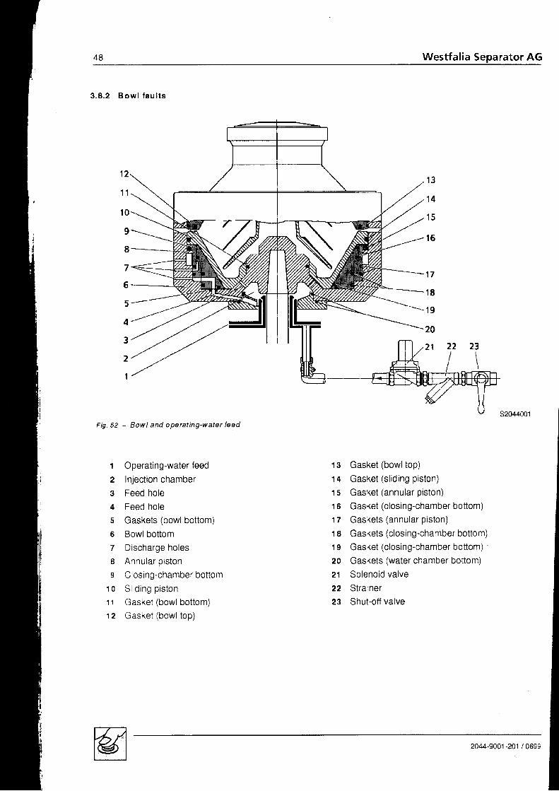
3 .8 .2 B ow l f au l t s
Fig. 52 - Bowl and operating-water feed
t Operating-water feed
2 Injection chamber
3 Feed hole
+ Feed hole5 Gaskets (bowl bottom)5 Bowlbottom7 Discharge holes8 Annular piston
s Closing-chamberbottom1 o Si iding piston
11 Gasket (bowl bottom)12 Gasket (bowl top)
r3
1 4
1 5
t 6
7
6
5
3
2
I
13 Gasket (bowl top)
14 Gasket (sl id ing piston)
1s Gasket (annular piston)
16 Gasket (closing-chamberbottom)
17 Gaskets (annular piston)
18 Gaskets (closing-chamber bottom)
19 Gasket (closing-chamber bottom)
20 Gaskets (water chamber bottom)
21 Solenoid valve
22 Strainer23 Shut-otf valve
1 7
1 8
1 9
20
2044-9001-201 /0699

, ator AG 49
bt t P o s s i b l e c a u s e s R e m e d i e s
Holes 3 or 4 or 7 in bowl bottom areblocked orthe injection chamber is dirty,
Clean holes and injection chamber
A rim of dirt has deposited beneath thesl iding piston.
Dismantle the bowl and clean i t .
Gaskets are damaged or their edgeshave been frayed due to the up anddown movement of the annular oistonand sl iding piston.
Replace gaskets.
ooes not close Gasket 12 in bowttop is damaged. Replace gaskets.
The seal ing edge of the sl id ing pistonis damaged.
Light ly face seal ing edge of s l id ing pis-IOn Orsend piston to factory for repair.
cces not open at al lcompletely.
The operating-water feed rate is toolow.
Check water pressure.lf necessary, increase pressure,Operating-water data:- P ressu re2 -5bar- Volumeof f lowmin. 3 000 t/h (gauge
the capacity by l itres) = 1 ,6 | in 2 sec
Strainer in operating-water line is dirty, Clean strainer
Gasket in operating-water line is dam-aged. Part of the operating water getslost.
Replace gasket in operating-waterl ine .
Passage section of operating-waterline has become too narrow due to dirtaccumulat ion or damage. The amountof operating water flowing into the in_jection chamber is insufficient.
Clean or replace operating-water line.
The operating-tiquid shut-off deviceooes not open properly
Replace shut-off device,
w" ('/-{ |i(rr) It . - . I
Westfalia Separator AG
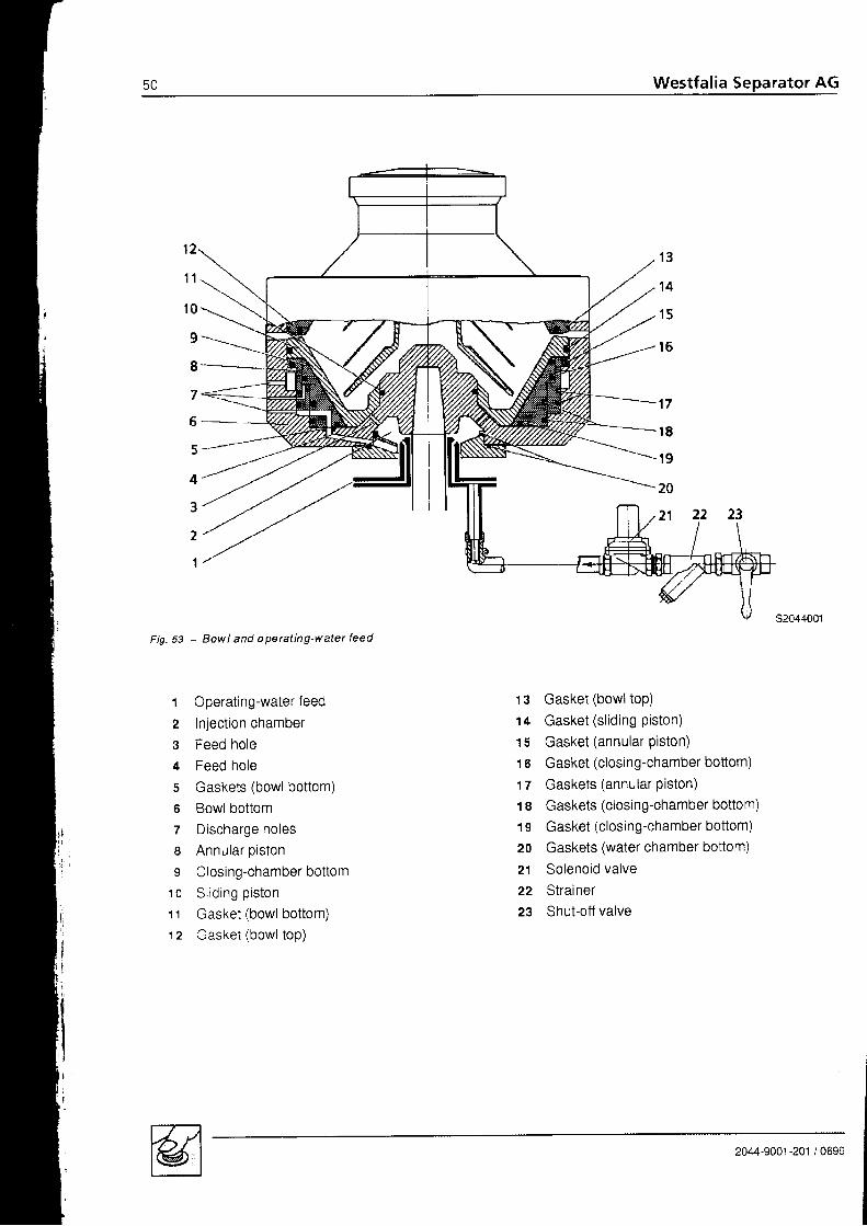
Bowl and operating-water feedFig.53 - Eowl and oPeratng-water
t Operating-water feed
2 Injection chamber
3 Feed hole
c Feed hole
s Gaskets (bowl bottom)
o Bowlbottom
7 Discharge holes
B Annular piston
s Closing-chamberbottom1o S l id ing p is ton'11 Gasket (bowl bottom)12 Gasket (bowl top)
13 Gasket (bowl top)
14 Gasket (sl id ing piston)
15 Gasket (annular piston)
16 Gasket (closing-chamber bottom)
17 Gaskets (annular Piston)18 Gaskets (closing-chamber bottom)
19 Gasket (closing-chamberbottom)
20 Gaskets (water chamber bottom)
21 Solenoid valve
22 Strainer23 Shut-off valve
2044-9001 -201 / 0699

Westfalia
F a u l t P o s s i b l e c a u s e s
-he bowl does not open at al l
c' not comptetety. (cont'd.)Dry dirt or rubber particles have setfled- between centrifugation chamber
bottom and annular piston or- between annular piston and bowl
bottom or- between sliding piston and bowl
bottom.
Clean bowl parts
Replace damaged gaskets.
Grease guide surfaces (see lubrica-t ion p lan) .
The closing chamber is dirty. Dismantle the bowl.Clean the closing chamber.
Gasket 12 of polyamide fits loosety inthe groove of bowltop.Process liquid seeps into the gasketgroove and presses the gasket out ofthe groove white the stiding pistonmoves downwards, so that there is nogap for sludge ejection.
Replace polyamide gasket.
ncomplete solids ejection ofihe bowl. Sludge remains inrhe bowl.
Feed rate of operating water is toolow.
Check line oressure.lf necessary, increase pressure.Operating-water data:- P ressu re2 -Sbar- Volume of flow min. 3 000 l/h (gauge
the capacity by l itres) = 1 .6 | in 2 sec
The bowl has closed too soon. Solidparticles which could not be ejectedhave gradually accumulated in thebowl and hardened through the longtime of centrifugation.
Clean the bowl.
Leave operating-water valve open forabout 10 seconds.
lf necessary, carry out flush de-sludg-ings after de-sludging
The pressure in the disc stack hasslackened or is too low due to an insuf-ficient number of inserted discs. As aresult the discs have deformed.
Add spare disc or compensating disc.Re-shape deformed discs. lf neces-sary. replace them.
2044-9001-201 /0699
sz Westfalia Separator AG
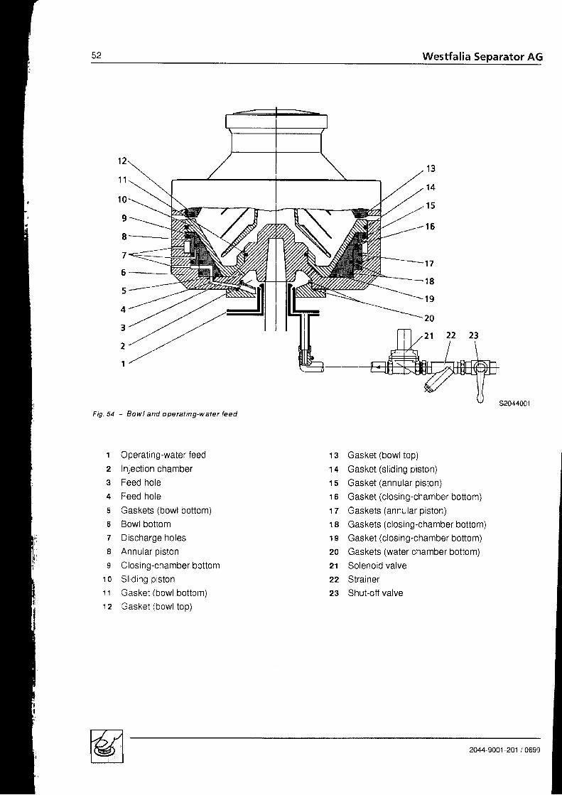
s2044001Fig.54 - Bowl and operct ing-water feed
1 3
1 4
1 5
1 6
t Operating-water feed
2 Injection chamber3 Feed hole4 Feed hole
s Gaskets (bowl bottom)6 Bowl bottom7 Discharge holes8 Annular piston
s Closing-chamberbottom10 S l id ing p is ton
11 Gasket (bowl bottom)12 Gasket (bowl top)
13 Gasket (bowl top)
14 Gasket (sl id ing piston)
15 Gasket (annular piston)
16 Gasket (closing-chamber bottom)17 Gaskets (annular piston)
18 Gaskets (closing-chamber bottom)19 Gasket (closing-chamber bottom)20 Gaskets (water chamber bottom)21 Solenoid valve
22 Strainer23 Shut-ofl valve
1 7
1 8
1 9
20
2044-9001-201 /0699

F a u l t P o s s i b l e c a u s e s R e m e d i e s
Gasket in bowl top becomesworn too rapidly.
Bowl has closed too soon,Solids have been oressed into thegasket by the rising piston.
Leave shut-off device for operatingwater open for about 1 0 sec.
The process liquid contains abrasivesol ids.
Prestrain process I iquid.
The bowl opens after a longseparat ing t ime.
The operat ing- l iquid votume in theclosing chamber has decreased dur-ing a long separat ing t ime (due toevaporat ion, etc.) .
Check operating-water valve and con-trol uni t .
The bowl does not close oropen properly after a long-term shut-down of the seoa-rator,
The bowl has not been cleaned thor-oughly before a long-term shut-downof the separator. Scale has setiled anddried up:- between centrifugation chamber
bottom and annular piston or- between annular piston and bowl
bottom or- between sliding piston and bowl
bottom
Before removing- the centrifugation chamber bottom- the sl id ing piston ano- the annular pistondislodge the dr ied-up scale using ci t r icacid in the gaps- between centrifugation chamber
bottom, sl id ing piston and annularpiston or
- between sliding piston and bowlbottom.
Then dismantle the bowl and clean i tthoroughly.
ihe discharging clean oi l isCrrty due to overflow of bowl,
lmpuri t ies of high density (e.9. rustfrom tanks and pipe lines) have col-lected in the distributor neck. The feedto bowl is hindered, resulting in over-flow,
Clean distributor neck,
II
Eaa-s661 -26' ' OUnn

Westfal ia Separator AG
4 . 14 . 1 . 14 . 1 . 24 . 1 . 34 . 1 . 44 . 1 . 54 .24 . 2 . 14 .2 .24 .2 .34 . 2 . 44 .34 . 3 . 14 ,3 .21+. J . J
4.3 .44 . 3 . 54 . J , O
4.3 .74 . 3 . 84 .44 .4 .14 .4 .24 .4 .34 .54 . 5 . 14 ,5 .24 .5 .34 .64 . 6 . 14 .6 .24 .6 .34 . 6 . 44 .6 .54 . 6 . 64 .74 ,84 . 8 . 14 .8 .24 .8 .34 .94 .9 . '14 .9 .24 . 1 0
Installation of the plantConnect ing the plant .Fastening the separatorMotor connectionDirection of rotation of the bowlSpeed and starting time of bowl .Maintenance and lubrication . . .Lubrication and maintenance schedule . . . .Lubricat ionLubricat ion ChartWear to gear .BowlDismantl ing the bowlCleaning the bowl . .Cleaning the upper section of frameCleaning the strainer and the operating-water feed systemlmportant hlntsAssembling the bowl .Replacing the polyamidegasket in the annular pistonReplacing the polyamide gasket (bowt top)Vertical gear parts 1Removing the vertical gear parts 101Cleaning the gear chamber .105Re-assembly of vertical gear parts ruoHeight adjustment 1.10Bowl he igh t 110C e n t r i p e t a l p u m p c l e a r a n c e . , . 1 1 1Neck bear ing 113Motor and centrifugal clutch 114
6 A
5 7
O U
o l
oz
oz
64
70t z
7382a e
RR
848797
00
Removing the motor .Prior to fiiting the motoiFitting the motorRemoving the clutch shoes .Fitting the clutch shoesFit t ing the clutch dr iverRemoving the gear pump and pump coupling . .Horizontal gear partsRemoving the worm wheelBefore a long-term shut-down of the separatorFitting the worm wheelRemoving the clutch drum and worm wheel shaftInstallation of the worm wheel shaft and the clutch drum . . . .Instal lat ion of the seal ing r ings
1 1 5t t o
1171 1 81 1 91201211 2 2123125t z o
1281 3 01 3 0l \ ]
2044-9001-201 /0699
Final checks after assembling the separator

Westfalia
a - l . 1 C o n n e c t i n g t h e p l a n l
1 4 1 5
Fig. 55 - Connection diagram of the separctor planl
I12
'//->
/ ,
1
234567I9
1 01 11 21 41 51 51 71 81 9202 1222324252627293 0
Producl feedShul-off devicePreslrainerGear pumpPre-sel valveSleam-heated oil prehealerAutom. lemperalure regulalorSleam inletSafely valveLeak oil to overflow lankCondensale oullelDrain and venl cockFlowmelerPressure gaugeThermomelerCenlrifugeNon-relurn valvc with shut-off deviccProducl dischargeFeed line assemblyOperating-waler dischargeWaler dischargeSludge dischargeShul-off device (operaling water)Pressure gauge (operaling water)Waler feedMotor conlrolHoistPressure swilch for clean oil discharge
P2044m3
S u b j e c t t o m o d i f i c a t i o n !
\\',6<S
2044-9001-201 /0699

5 d Westfalia Separator AG
4 . 1 . 2 F a s t e n i n g t h esepa ra to r 1
z
4E
o
Securing the separatoron metal foundation
Sh ipboa rd ope ra t i on
Securing the separatoron stone foundation
c2042m3O n s h o r e o p e r a t i o n
F ig .56
1 Hexagon nutz Cup springss Stud4 Upper cap
s Rubber cushion6 Lower cap7 Anchor bolt
Tighten lower hexagon nut. by hand,. by a further full rotation using a
single-ended wrench.. Secure it using a second hexagon
nut ,
{
I
For further detai ls, refer to the instal lat ion hints
2044-9001-201 /0699
a l i a S rator AG
I o t o r c o n n e c t i o n
r00%
90
80
70
60
50
rto
30
20
1 0
2s 5075 100%
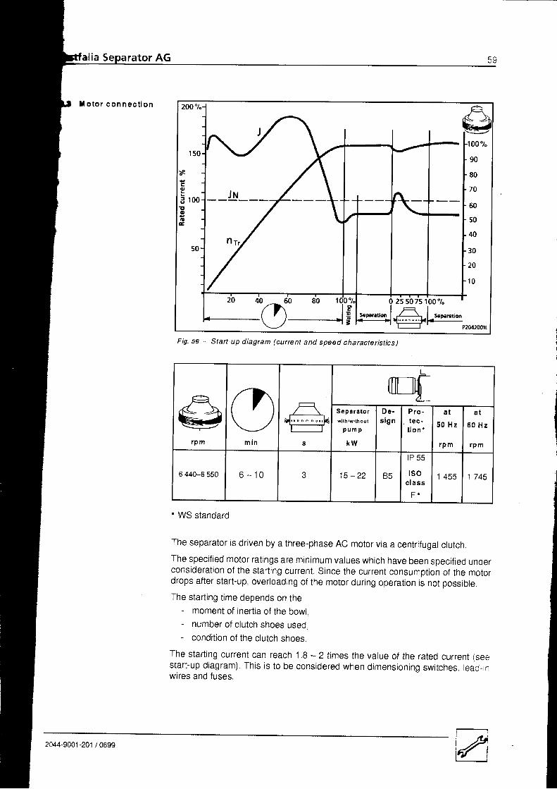
Fig,58 - Start-up diagram (current and speed charactetistics)
r p m m t n s
Sepa ra to rw l t h / w l l h o u t
p u m p
K W
D e -s i g n
P r otect io n
a t
5 0 H z
rpm
a t
6 0 H z
rpm
5 440-6 550 6 - 1 0 1 5 - 2 2
lP 55
tsoc l a s s
F r
| 4 C 3 1 745
. WS standard
The separator is driven by a three-phase AC motor via a centrifugal clutch.The specified motor ratings are minimum values which have been specified underconsideration of the starting current. Since the current consumption of the motordrops after start-up, overtoading of the motor during operation is not possible.
The start ing t ime depends on the- moment of inertia of the bowl,- number of clutch shoes used,- condition of the clutch shoes,
The starting current can reach 1.9 - ztimes the value of the rated currenr (seestart-up diagram). This is to be considered when dimensioning switches, tead-inwires and fuses.
2044-9001-201 /0699
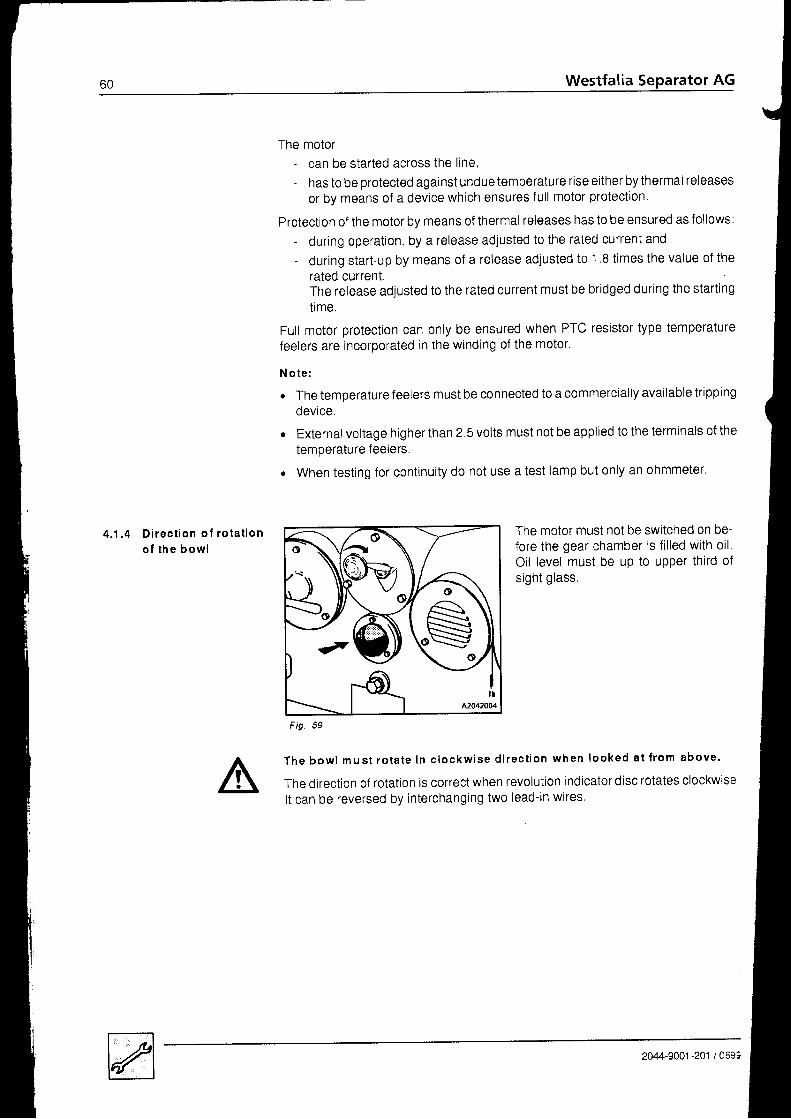
4 .1 . 4 D i rec t i on o f r o ta t i ono f t h e b o w l
The motor- can be started across the line,- has to be protected against undue temperature rise either by thermal releases
or by means of a device which ensures f ull motor protection
Protection of the motor by means of thermal releases has to be ensured as follows:- during operation, by a release adjusted to the rated current and- during start-up by means of a release adjusted to 1 .8 times the value of the
rated currentThe release adjusted to the rated current must be bridged during the startingi lme.
Full motor protection can only be ensured when PTC resistor type temperaturefeelers are incorporated in the winding of the motor.
N o t e :
r The temperature feelers must be connected to a commercially available trippingdevice,
r Externalvol tage higher than 2.5 vol ts must not be appl ied to the terminals of the
temperature feelers.
. When testing for continuity do not use a test lamp but only an ohmmeter.
The motor must not be switched on be-fore the gear chamber is fil led with oilOil level must be up to upper third ofsight glass.
T h e b o w l m u s t r o t a t e i n c l o c k w i s e d i r e c t i o n w h e n l o o k e d a t f r o m a b o v e .
The direction of rotation is correct when revolution indicator disc rotates clockwiseIt can be reversed by interchanging two lead-in wires
F ig.
2044-9001 -201 / 0693

Westfalia Separator AG
4 .1 . 5 Speed and s ta r t i ngt i m e o f b o w l
The bowl speed has been rated so as to ensure the operating safety of the separ-ator,
lf the densities exceed those specified above, check with the factory
R svo lu t i o ni n d i c a t o r d i s c
A214600 r
F i g . 6 0
. Check speed of spindle (= speed ofbowl) with a hand tachometer:- before initial start-up,- after changing gear parts.
. Check before instal l ing the bowl.
The ro ta t ing revo lu t ion ind ica tordisc shows that the bowl is rotating andin which direct ion.The bowl has reached its full speed.when the revolution indicator discmakes the following revolutions:
Motor soeed65 rpm -) n = 1 455 rpm78 rpm -> n = 1 745 rpm
Speed variations up to 5 % are permiss-ib le .
Speed for densit ies- of heavy l iquid up to max. 1.05 kg/dm3
and- of centrifugally dry solids up to max.
1.4 kg/dm3
6 440-€ 550 rpm
Sta r t i ng t im e 6 - 1 0 m i n
2044-9001 -201 / 0699

62 Westfalia Separator AG
4 . 2 M a i n t e n a n c e
4 . 2 . 1 L u b r i c a t i o n
a n d l u b r i c a t i o n
a n d m a i n t e n a n c e s c h e d u l e
{
K o y :
E = Whenever changing oi l . c lean gear chamber lhoroughly.E = see sect ion 4 2 2 - o i l qual t ty
B = see secl ion 4.2 3 - lubr icatron char l
E = Wc rccommcnd thc synthclrc grcasc Mobilith SHC 100 or SHC 460 for grcasing this part; il has givcn good rasults in praclice
I
a f t e r f o l l o w i n g o p e r a t i n g h o u r s
O P E R A T I O N S
a t t h e l a t e s t e v e r y
750 1 5 0 0 4 0 0 0 8 0 0 0 1 5 0 0 03
m o n t h s
6m onth !
1yarr
2y a a r s
L U B R I C A T I O N
o First oil change after init ial start-up. o oweek l y Check oil level week l y
o W h e n u s i n g m i n e r a l o i l : BOil change and thorough cleaning of gear chamber. tr o
o W h e n u s i n g s y n t h e t i c o i l : E
Oil change and thorough cleaning of gear chamber. E ow h e n e v e r d l s m a n t l i n g Grease sliding and guide surfaces of main bowl parts. tr o
o Remove. clean and greaseur the bowl lock r ing. and re-in-stal l i t . o
M A I N T E N A N C E
C l e a n i n g
wh en req u l r ed -p r o d u c t - d e p e n d e n t Clean fi l ter in suction l ine of product pump. o
when requ i r edClean strainer in operating-liquid l ine and on water-pres-sure reducer. o
o W h e n u s i n g m i n e r a l o i l : B
Clean gear chamber (oi l change) o
o W h e n u s i n g s y n t h e t i c o i l : t rC lean gear chamber (o i l change) . o
O Remove bottom bearing, and check and clean all parts tho-roughly. o
o Remove bowl and clean inside of upper section of frame. o
oDismantle the bowl.Clean allbores. nozzles and chambers of hydraulic system.When f itt ing, the cones of the spindle and bowl must be dryano c lean.
o
l n s D e c t i o n
o Remove and replace bowl gaskets (see 4.3.5).Check gasket grooves for corrosion after cleaning. o
o Check starting i ime.Check thickness of clutch l ininqs o
o Check thickness of brake l ininos oo Check ball bearings of spindle. o
o Check cylindrical pressure springs in neck bearing. oo Check gearing of worm gear through inspection hole after
removino the revolution indicator housino. o
2044-9001 -201 1069':

a f t e r f o l l o w i n g o p e r a t i n g h o u r s
O P E R A T I O N Sat the la tes t every
750 1 5 0 0 4 0 0 0 I 0 0 0 1 6 0 0 03
n o n t h g
6m o n l h s
I
y c a f
2y .ars
I n spec t i on
o Check if monitoring system functions correctly oo Check sp ind le speed (bowl ) : in case o f ro ta ry cur ren t
(only after changing the gear). oo Check spindle speed (bowl) : in case ot d i rect current
(only after changing motor and gear). oR ep lacem en t
o Clutch shoes oo Ball bearings on spindle o
o Ball bearings on worm wheel shaft oa f t e r 4 0 0 0 0 o p e r a t i n g h o u r s
Equip the machines with new vibration absorbers.We recommend having the machines checked by a WSservtce enqtneer.
af te r 5 years
on your daily round - especial ly during the f irst 1500 operating hours. Oi l level. Temperaturesr Pressures. Leakages. Vibrations. Power consumption. Starting time
- pay attention to the following:
I r y :Whenever changing oil, clean gear chamber lhoroughly.see seclion 4.2.2 - oil qualitysee section 4.2.3 - lubricalion chartwe recommend lhe synlhelic grease Mobilith SHc 100 or sHC 460 for greasing lhis parl; il has given good resulls In praclice
2C.4-9001 -201 / 0699
64 Westfalia Separator AG
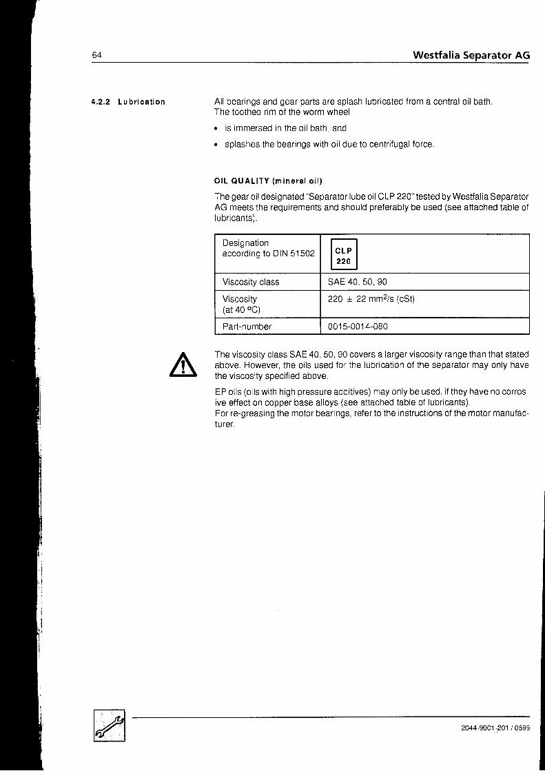
4 .2 ,2 Lu b r i ca t i on All bearings and gear parts are splash lubricated from a central oil bath.The toothed rim of the worm wheel
. is immersed in the oil bath and
. splashes the bearings with oil due to centrifugal force.
O I L O U A L I T Y ( m i n e r a l o i l )
The gear oil designated "Separator lube oil CLP 220" tested by Westfalia SeparatorAG meets the requirements and should preferably be used (see attached table oflubr icants).
The viscosity class SAE 40, 50, 90 covers a larger viscosity range than that statedabove. However, the oils used for the lubrication of the separator may only havethe viscosity specified above.
EP oils (oils with high pressure additives) may only be used, if they have no corros-ive effect on copper base alloys (see attached table 0f lubricants)For re-greasing the motor bearings, refer t0 the instructi0ns 0f the motor manufac-IUrer.
Designat ionaccording to DIN 51502 trViscositv class sAE 40, 50, 90
Viscosity(at 40 oC)
220 + 22 mmz/s (cst)
Part-number 001 5-001 4-080
2044-9001-201 i 0699

Westfalia Separator AG 65
Designationaccording to ISO
M o b i l S H COJU
Viscosity class tso-vc 220
Viscosity
- a t 4 0 0 c
- at 100 oC
218 mm2/s
25.9 mm2/s
Viskosity index (Vl) 152
Density (at 15 oC) 0 868
based on Polyalphaolef in
Part-Number 001 5-001 8-200
Disposal as per instructions of the ojl company.
O I L Q U A L I T Y ( s y n t h e t i c o i l )
As syntholub the synthetic gear oit tested by westfalia separator AG shoutd beused I
Do not use synthetic motor vehicle gear or engine oi ls.
P r e - c o n d i t i o n s f o r u s i n g s y n t h e t i c l u b e o i l :
. The gear- must be run in with mineral lube oi l (approx. 1 500 operat ing hours)- must display clear ly vis ible running-in marks.
b = m i n . 2 - 3 m m
Fig
2044-9001 -201 / 0699

Westfalia Separator AG
ln terva I
R u n n i n g
t im e wi tho i l
( h )
S ta tus I Ope ra t i onL u b r i c a n t
Symbol Desc r i o t i on
Before firslstart-up oratter gearchange
0 . F i l l i n o i l . Mineral oi laccording too t N s r 5 t z E
Every week . Check oil level.
Afier 750operating hours
o Firsl running-in phasecompleted.
. Carry out lirsl oil change,
Mineral o i laccording 1oottrt stslztr
Every week . Check oil level.
After 2 500operaling hoursal lhe latesl
750 lo I 750(depends onthe deplh of
the run-ning- inmarks)
When the running-in markscorrespond io the previousolagram:. Second running-in phase
is compleled.. Carry oul second oil
cnange.
CLP HC Synlhelic oil
Every week . Check oil level.
After 4 000operaling hoursal lhe latesl
1 500 a Flush phase completed.
Carry out lhird oil change.
CLP HC220
Synlhetic oi l
Evcry 4 000operaling hoursorevery 1.25years
4 000 . Normal opcrationo Oil change
CLP HC220
Synthctic oi l
[| Refer to lhe lable of lubricants supplied with the separator.
I
I
S c h e d u l e f o r s w i t c h i n g t o s y n t h e t i c l u b e o i l
S y n t h e t i c l u b e o i l s
tsov l s c o s l t y
c l a B g
V isc o s i t y(m m 2/s) V l scos l t y
l n d e xV I
Dsn s l t ya t 1 5 o C{g / cm 3 )
B a s e
4 0 0 c 1 0 0 0 c
Mobil SHC 630(WS part-no.:001 5-001 8-200)
lso-vG 220 218 152 0.868 Polyalphaolef in
Shel lDel ima HT 220
tso-vG 220 24.1 l e q 0.879 Polyalphaolcf in
CaslrolAlphasyn T 220 tso-vG 220 220 zo 152 0.867 Polyalphaolefin
BPEnersyn HfX220 tso-vG 220 1 5 5 0.869 Polyalphaolefin
EssoTeresso SHP 220 rso-vG 220 211 24.7 t + o 0.845 Polyalphaolefin
Lub Marine (ELF)EPONA SA 220 tso-vG 220 220 zo 1 5 0 0.86 Polyalphaolefin
2044-9001 -201 / 0699

O I L L E V E L
Before starting the separator for thefirst time,o f i l l the gear chamber with oi t through
the f i l l ing hole on the revotut ion indi_cator.
F i l l i ng : approx . 7 |M i n i m u m o i l l e v e l :s l ight ly above middte of s ight gtassM a x i m u m o i l l e v e l :up to upper third of s ight gtass
F ig.
During operation the oir rever must never drop berow the minimum rever; be sure torefi l l in good t imel
O I L C H E C K
. Check the oil level weeklyl
' After loosening the oil drain screw, check from to time whether the oit containswater. l f the oi l shows a mi lky colouring (emulsi f icat ion), change the oi l immedi_ately.
O I L C H A N G E
. Carry out the first oil change after 750 operating hours
. Subsequently change the oil after every- 1 500 operating hours or 6 months at the latest (mineral oil),- 4 000 0perating hours or 15 months at the ratest (synthetic oir)
r whenever changing the oi l , thoroughly clean the gear chamber with thin-bodiedot l .
. Carefully remove metal particles from the wall and corners.o Do not use fluffy cleaning rags (no cotton waste)l. Clean the sight glass.
(After some time a rim forms on the inside of the sight glass which can be easilymistaken for the oil level.)
2044-9001 -201 / 0699

Westfalia Separator AG
4 . 2 . 3 L u b r i c a t i o n C h a r t
Fig.63 - Lubrication diagram
2044-9001 -201 / 0699
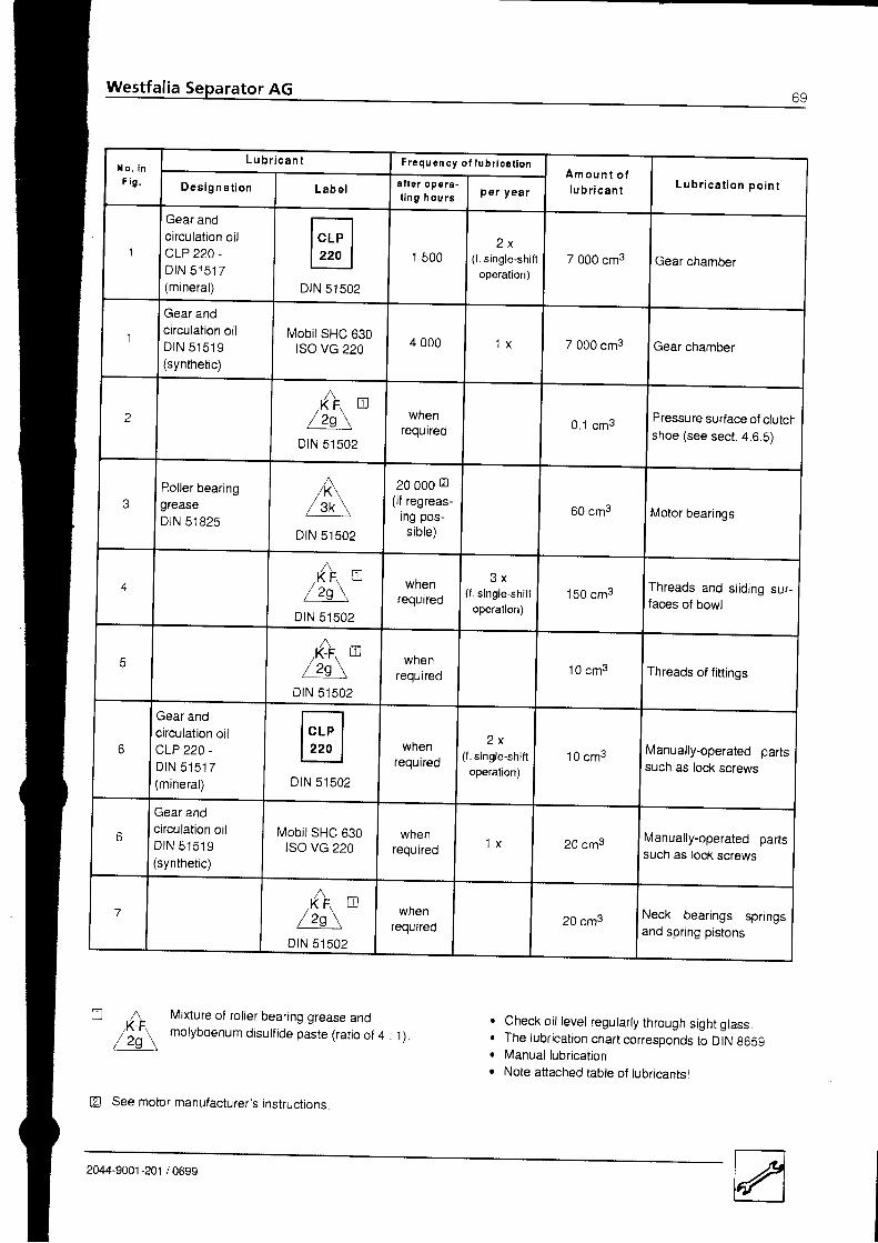
X o . i nF i g .
L u b r i c a n t Frequ en cy o f l ub r i ca i l onA m o u n t o fl u b r i c a n t L u b r i c a t i o n p o i n tD e s i g n a t i o n L a b e l a f t e r ope ra -
t i n g h o u r s Per year
'I
Gear andcirculation oilCLP 220.D t N 5 1 5 1 7(mineral) D tN 51502
1 5002 x
(f. single-shifl
operation)7 000 cm3 | Gear chamber
Gear andcirculation oilD t N 5 1 5 1 9(synthetic)
Mobi l SHC 630rso vc 220 4 000 '1 x 7 000 cm3 Gear chamber
2
n,K F, LIJ
/ z g \DtN 51502
wnenrequtred 0.1 cm3
Pressure suriace of clutchshoe (see sect. 4.6.S)
3Roller bearinggreaseDIN 51825
/\/ 3 k \
DtN s1502
20 o0o E(if regreas-
ing pos-sible)
60 cm3 Motor bearings
+
n, K F 0
/ 2 s \DIN 51502
wnenrequired
3 x(f . single-shif t
operalion)150 cm3
Threads and sliding sur-faces of bowl
F
n/K-F\ Ul
/ 2 s \DtN 51502
wnenrequired
'1 0 cm3 Threads of fittings
Gear andcirculation oilCLP 220 -
D I N 5 1 5 1 7(mineral) DrN 51502
whenrequired
2 x(f. single-shifl
operation)10 cm3 Manually-operated parts
such as lock screws
o
Gear andcirculation oilD t N 5 1 5 1 9(synthetic)
Mob i lSHC 630tso vc 220
whenrequired
'1 x 20 cm3Manually-operated partssuch as lock screws
n,K F, {.LJ
/ 2 s \DtN 51502
wnenrequired 20 cm3 Neck bearings springs
and spring pistons
,A/ z g \
Mixture of roller bearing grease andmolybdenum disulfide paste (ratio of 4 : 1).
Check oil level regularly through sight glassThe lubrication chart corresponds to DIN g659Manual lubricatlonNote attached table of lubricantsl
I
a
!
a
See motor manufacturer's instructions
2044-9001-201 /0699
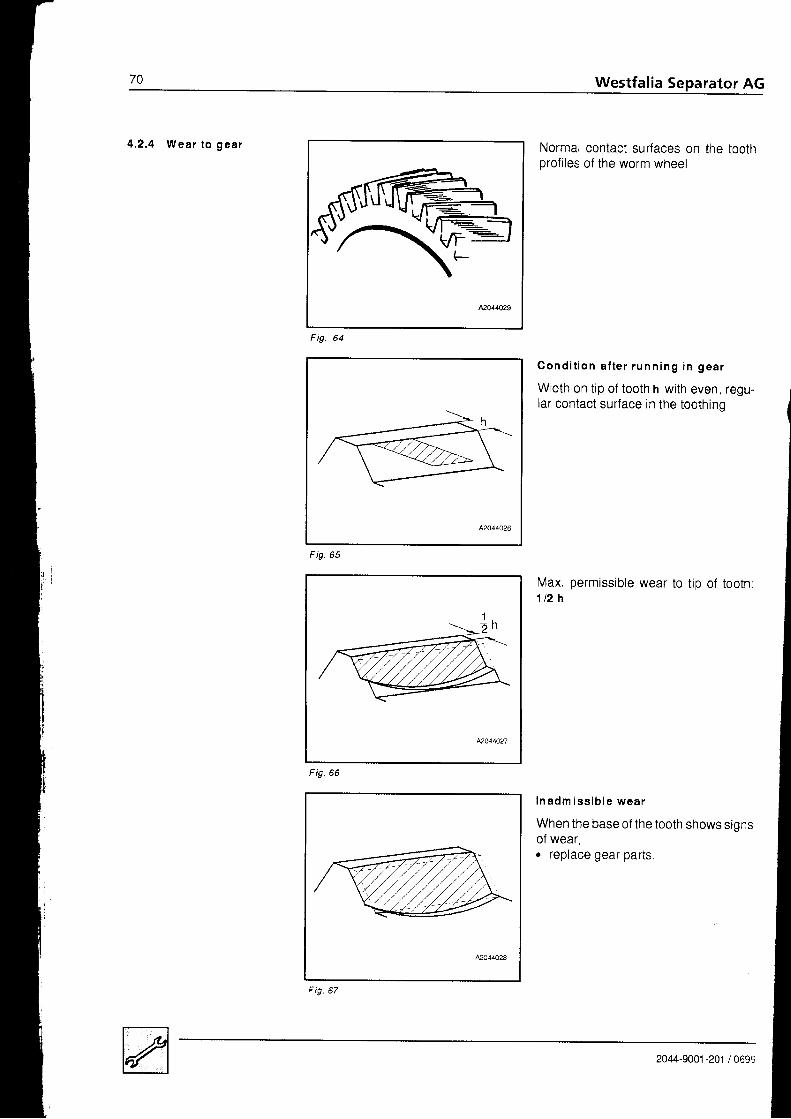
Westfalia Separator AG
4 .2 .4 Wear t o gea r Normal contact surfaces on the toothprofiles of the worm wheel
C o n d i t i o n a f t e r r u n n i n g i n g e a r
Width on tip of tooth h with even, regu-lar contact surface in the toothino
Max. permissible1 t 2 h
wear t0 tip of tooth:
I n a d m i s s i b l e w e a r
When the base of the tooth shows sionsof wear,. replace gear parts,
Fig
F ig .66
I
Fig
2044-9001 -201 / 0699

Westfalia Separator AG 7 1
observe the following to attain max. possible service life of the gear:o Follow the standard maintenance instructions.o Use approved synthetic lube oils as specified in chapter 4.2.2. Regular ly check the lube oi l level.' Check the bowl starting time (if necessary, reduce the number of ctutch shoes).. Avoid external viibrations.' Assemble and maintain the foundation components as directed.' Remove the bowr when the separator is shut down for a rong period.
In fo rmat ion on gear wear
In the case of short gear service lives caused by. uneven wear to gear (unbalance),r Pittings on the contact surfaces of the teeth.
consult Westfalia Separator AG,
I
IjIIIIII
2C44-9001-201 /0699
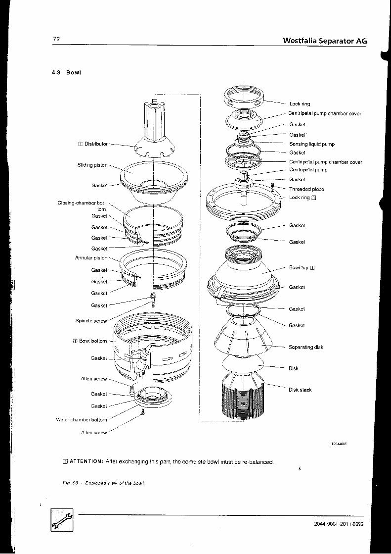
72 Westfalia Separator AG
4 . 3 B o w l
I Distributor
Sliding pislon
Gaskel
Closing-chamber bol-1om
Gaskel
Gasket
Gaskel
Gaskcl
Annular piston
Gaskel
Gaskel
Gasket
Gaskel
Spindle screw
E Bowl boltom
Gaskel
Lock ring
Centripetal pump chamber cover
Gasket
Gasket
Scnsing l iquid pump
Gasket
Centripelal pump chamber coverCenlripetal pump
Gasket
Threaded piece
Lock ring fl
Bowl lop I
Gaskel
Gaskel
Gaskel
Separaling disk
Disk
Disk slack
.T2044005
Al len screw
Gaskel
Gasket
Waier chamber bol lom
Al lcn screw
E ATTENTION: After exchanging this part, the complete bowl must be re-balanced
Fig . 68 - Exo loded v rew o f the bowl
2044-9001 -201 / 0699

4 .3 .1 D i sm an t l i ng t h e b o w l
NAt ten t ion !
To avo id acc idents do no t loosen any par t be fore the bowl i s a t a s tands t i l l !
The standstill of the bowl is indicated- by the standstill of the revotution indicator disc.
o Switch off the main switch and secure it,
o Handle bowl parts with care.
e For tools refer to sect. 5 - List of oarts,
{
F ig .69
F ig .70
o Disconnect water feed line.
Unscrew handle connection piece( le t t -hand th read) .Hold centr ipetal pump with thewrencn.
. Unscrew fastening screws. 1
2044-9001-201 /0699
Fig
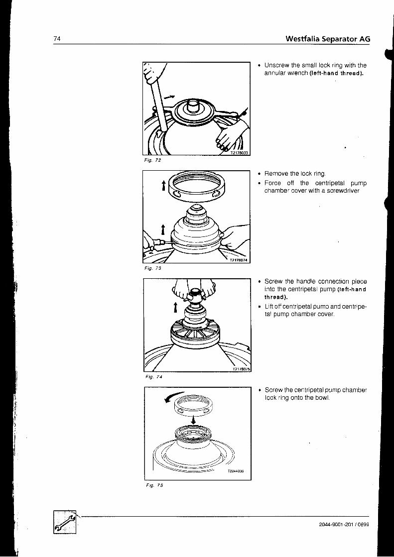
74I Westfalia Separator AG II
o
a
. Unscrew the smal l lock r ing with theannular wrench ( lef t-hand thread).
Remove the lock r ing.Force off the centripetal pumpchamber cover with a screwdriver.
Screw the handle connection oieceinto the centr ipetal pump ( letr-handth read) .
Lift off centripetal pump and centripe-tal pump chamber cover.
Screw the centripetal pump chamberlock r ing onto the bowl.
Fig.
F ig. 73
F ig.
2044-9001-201 /0699
/ cFig

.,,,.\,
I ":- \\-1
\.
F ig .76
Place centripetal pump and centripe_tal pump chamber cover on lock ring.Place a hard-wood block on thehandle connection piece.Separate the sensing l iquid pumpfrom the centripetal pump by tighttaps with a hammer.
Unscrew spindle screw with wrench( l e f t - hand th read ) andremove it.
Force bowl off the spindle cone uslnothe pul l ing device andlift it out of the frame.
Yr' 'y 'Tl1, !,t
T2044018
7J449001-201 t0699
Fig 78

76 Westfalia Separator AG
. Screw on compressing device
. Screw bolt into the distributor
. Comoress the disk stack
. Tightly screw on the pin spanner.
Str ike open the bowl lock r ing l tet t-h an d th read ) .
i
2044-9001 -201 / Ofi

Westfalia Separator AG
o Lift off the bowt lock ring using the pins0anner.
. Unscrew the bolt from the distributor.
. Lift off the bowt top with the aid of thecompressing device.
. Remove the separating disk
. Check gaskets A and B,o replace them if damaged
l lr lII
20c.1-s061 -ro1 , ornn
Fig.

rze Westfalia Separator AG
F ig. 87
. Screw the disc stack compressingdevice into the distributor neck
Take out the distributor and diskstack by means of the compressingdevice.
o Insert pressure piece.
Screw the mountingsliding piston.
tool onto the
2044-9001 -201 / 0699

Westfalia Separator AG 79
r Force off the sliding piston
Take out the sliding piston with themounting tool .
Turn the bowl bottom onto its sidewith the aid of the pul l ing deviceSecure it against rolling away andtoppling over.
. Undo Al len screws
a
a
-\c-=\\
:==\-
2044-9001-201 /0699

80 Westfalia Separator AG
a
a
Place plate 2 on mounting tool '1.
Insert the mounting tool in the bowlbottom.
Bolt the mounting tool to the closingchamber bottom.
Insert angle piece 1 .Force off closing chamber bottom 2by turning the spindle.Lift out closing chamber bottom 2.Take out angle piece 1 .
Screw components 2-8 to mountingplate 1 andsl ide them in the slots towards thecentre of the bowl.Insert the mounting tool in the bowl
a
a
a
a
i
F i g . 9 5
F ig.
2044-9001 -201 / 0693

Westfalia Separator AG R 1
. Displace device 1 in the slots of themountrng plate towards the peri-phery.(Disk 2 catches under the annularpiston.)
. Tighten wing nut 3.
Force off the annular piston by turn-ing sp ind le 1 .Li f t out the annular oiston.
When exchang ing the gaskets in thew a t e r - c h a m b e r b o t t o m :. Turn bowl through 180., .o Unscrew the Allen screws from the
water-chamber bottom.. Screw two Allen screws
- into oppositetapholes of thewater-chamber bottom.
- By doing so force off the water-chamber bottom.
. Remove water-chamber bottom.
Fig 1 0 0
I
I1 0 1Fig.
p.4.9001 -201 / 0699

oz Westfalia Separator AG
t4 . 3 . 2 C l e a n i n g t h e b o w l Normally self-cleaning bowls need not be dismantled for cleaning at the end of a
run, unless the- nature of the process liquid makes bowl dismantling necessary or- the seoarator is to be shut down for an extended oeriod,
. Depending on the operat ing condit ions the bowl should be dismantled for inspec-t ion and cleaning from t ime to t ime. See sect ion 4.2.1 - Timetable for mainte-nance.
. For cleaning the individual discs and bowl parts
D o N O T u s e m e t a l s c r a p e r s a n d m e t a l b r u s h e s !
Take gaskets out of the bowl parts.
Clean grooves and gaskets to pre-vent grooves from corroding.Replace damaged, swol len. har-dened or brittle gaskets immediately.
Gaskets in bowl bottom and closing-chamber bottom which are frayed can bere-used after grinding them off with an emery wheel and turning them through'1800.
NOTE: Ensu re no t to dam age the sea l ing sur faces !
Special care should be taken in cleaning the small orifices for the feed and dis-charge of the operating liquid to ensure trouble-f ree performance of the ejection0rocess.
j
a
o
1 0 2F ig.
I
T2126040
Fig. 103
. Clean the distributor between the ribs- inside and outside - using a brush,Dirt accumulation in the distributorneck wil l hinder the feed. which mavresult in overflow.
Atter drying apply a thin film of grease t0 the guide surfaces and threads of thebowl parts (see lubrication chart).
Re-assemble the bowl immediately after cleaning.
--4'z- ' - : - ' - - 1 T 2 1 4 6 0 0 3
2044-9001 -201 / 0e9-:
Westfalia Separator AG Bs
Clean ing be fore a long- te rm shut -down o f the separa tor
Inadequate or negligent maintenance may lead to corrosion of the bowt oarts soonafter shutting down the separator.
. Clean separator thoroughly.
. WiFe dry and grease the cleaned and unvarnished machine parts to avoid cor-rosion.
o lt is recommended that the clean, greased bowl be kept in a dry place.. Check water shut-off devices for leakage.
lf necessary, disconnect water supply lines to avoid damage which may becaused by drip water
4 . 3 . 3 C l e a n i n g t h e u p p e rsec t i on o f f r am e
4 . 3 . 4 C l e a n i n g t h e s t r a i n e ra n d t h e o p e r a t i n g -water feed system
The inside of the upper sect ion of the frame must be cleaned from t ime to t ime.For this purpose remove the bowl.
Ensure that no cleaning l iquid seeps into the gear since i t would render the gearoil unserviceable.
Depending on the water and operating conditions, the strainer and the smail dis-charge holes in the operating-water feed system must be cleaned every 3 - 6months.
In case of calcification use a chemical cleansing agent.Thoroughly rinse the cleaned parts with water
2144-9001-201 /0699

84 Westfalia Separator AG
4 .3 .5 lm po r tan t h in t s The bowl rotates at a very high speed. Hence, forces are produced which can en-danger the operating safety of the separator in case of
- incorrect assembly of the bowl or- inadequate cleaning of the bowl
The instructions for assembly must therefore be followed exactly.
T h e f o l l o w i n g p o i n t s s h o u l d a l s o b e o b s e r v e d :
. Before assembling the bowl, check to be sure that the guide and contact sur-faces of the bowl oarts are clean.
. Grease guide surfaces in accordance with the lubrication chart.
. When fitting the bowl parts. makesure that the O marks on all parts arein line with each other.(Only then will the parts fit correctlyover arrest ing pins and guide r ibs.)
Fig. 104
lf the plant has several separators.be sure not to interchange parts ofd i f f e ren t bow ls (dange r o f unba l -an ce ) .
The oarts are marked- with the serial-number of the ma-
cnrne or- the last three digits of the serial-
number.
F ig . 105
Thoroughly grease the gasKetgrooves of the bowl parts and applya thin f i lm of grease,
Check that the gaskets are nottwisted.
1 0 6
(I
I
Fig
2044-9001 -201 / 0693
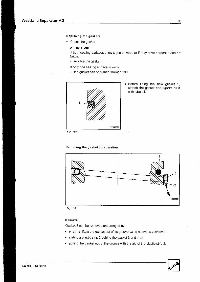
Westfalia Separator AG 8 5
R e p l a c i n g t h e g a s k e t s
o Check the gasket.
ATTEN TION:lf both sealing surfaces show signs of wear, or if they have hardened and arebrittle,- replace the gasket.
l f only one seal ing surface is worn,- the gasket can be turned through '180"
. Before fitting the new gasket 1,stretch the gasket and l ighr ly oi l i twi th lube oi l .
1 0 7F ig.
R e p l a c i n g t h e g a s k e t c o m b i n a t i o n
R em ova l
Gasket 3 can be removed undamaged by
r slightly lifting the gasket out of its groove using a small screwdriver,
. sliding a plastic strip 2 behind the gasket 3 and then
. pulling the gasket out of the groove with the aid of the plastic strip 2
1 0 8Fig
\
2c/,4-9001-201 / 0699

Westfalia Separator AG
2
3
Fig. 1 09
F i t t i n g
. Grease the outside of the annular piston.
e Insert gasket 1 into the groove.
o Press gasket 1 into the upper edge of the groove with a screwdriver.o Pull gasket 3 into the gasket with plastic strip 2.
o C h e c k :
- The gasket 3 must be seated evenly in the groove.- Gasket 3 may not protrude from the groove in mounting direct ion.
2044-9001,201 /0693

4 . 3 . 6 A s s e m b l i n g t h e b o w l For replacing the polyamide ring seesection 4 3.7.Insert gaskets 1 in the annular piston.Grease the guide surfaces as speci-fied in the lubrication chart.
Insert gaskets 1 and 2 in the ctosingchamber bottom.Do not yet insert a gasket in gasketgroove 3.Grease the guide surfaces as speci-fied in the lubrication chart.
Place closing chamber bottom 2 inannular oiston 1 .
Insert gasket 3chamber bottom.
in the closing
a
a
Fig. 11 0
F ig . 112
Fig
2044-9001 -201 / 0699
Fig. 11 3
t';

88 Westfalia Separator AG
. Grease the bowl bottom.
. Insert the pressure piece
Bolt the mounting tool to the closingchamber bottom.
Install the closing chamber bottomand annular piston in the bowl bot-tom.The "O' marks must be al igned.
Lower the closing chamber bottomby turning the spindle anticlockwiseWatch ior correct positioningl
F i g . 1 1 4
Fig. 11 5
a
a
F i g . 1 1 7
2044-9001-201 |

Westfalia
. Unscrew and lift out the tool
Turn the bowl bottom on to its sidewith the aid of the puiling device.Secure it against rolling away andtoppl ing over.
. Screw in Allen screws by hand
. Tighten the Al len screws to 1s0 N m.
Fig. 11 I
a
I
1 2 0Fig
tIl
i l /
Fig.
204+9001 -201 / 0699
t*,

Fig. 122
IWestfalia SeParator AG90
. Clean the bowl hub with a cloth.o The cone must be clean and dry.
Instal l the sl id ing piston using themounting tool .
o Take out the pressure piece.
Fig. 124
2044-9001 -201 / 0699
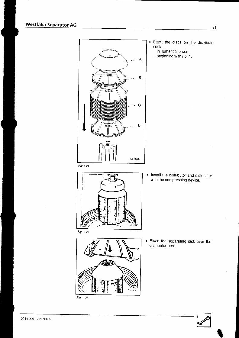
Westfalia Separator AG9 1
. Stack the discs on the distributorneck- in numerical order- beg inn ing w i th no . 1 .
Fig. 1 25
Install the distributor and disk stackwith the compressing device.
r Place the separating disk over thedistributor neck.
1 2 6F ig.
Fig. 127
2044-9001 -201 / 0699

YZ Westfalia Separator AG
F i g . 1 2 8
\ --/tt'12012047
o
a
Thoroughly clean grooves forgaskets A and B in the bowl top.lnsert gaskets.
For replacing the polyamide gasketrefer to sect ion 4.3.8.
Place on the bowl top with the aid olthe compressin g device.
. Screw the bolt into the distributor,
. Tighten the compressing device
a
a
I J UFig
Fig 1 4 1
2044-9001-201 /0693
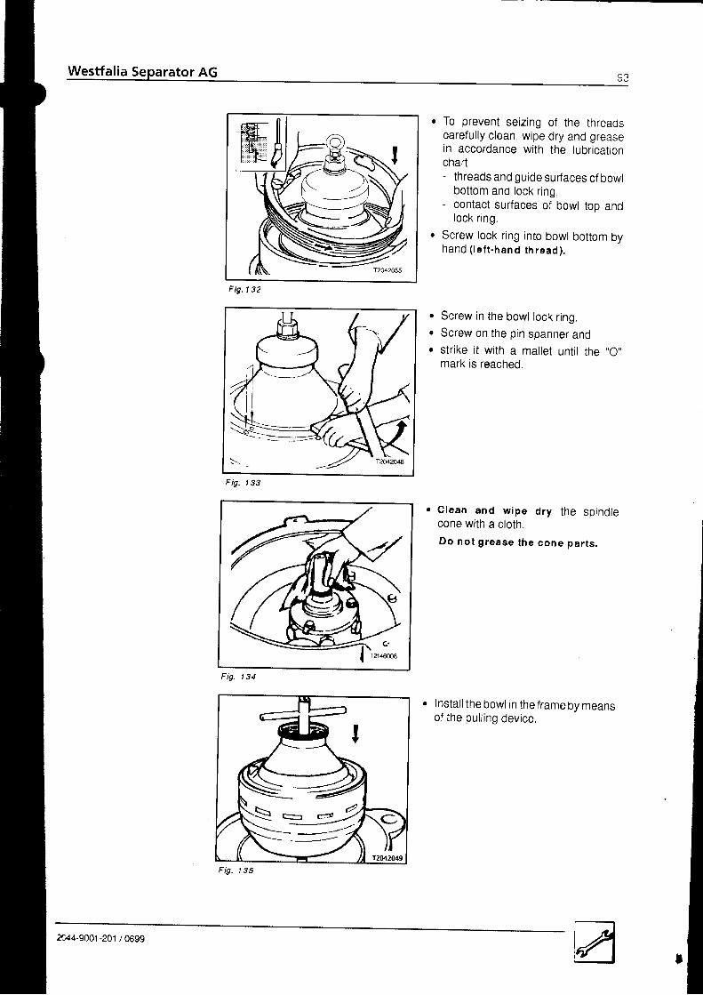
Westfalia Separator AG s3
F i g . 1 3 2
. To prevent seizing of the threadscarefully clean wipe dry and greasein accordance with the lubricationchart- threads and guide surfaces of bowl
bottom and lock r ing,- contact surfaces of bowl too and
lock r ing .. Screw lock ring into bowl bottom by
hand ( lef t .h an d th read ).
Screw in the bowl lock ring.Screw on the pin spanner andstrike it with a mallet untit the ,,O,,mark is reached.
Clean and w ipe d ry t he sp ind lecone with a cloth.
Do no t g rease the cone pa r t s ,
Instal l the bowl in the frame by meansof the pul l ing device.
a
a
a
1 4 2F ig.
I
Fig. 1 3 4
\ . _ * 9
&44-9001-201 / 0699
Fig 1 3 5
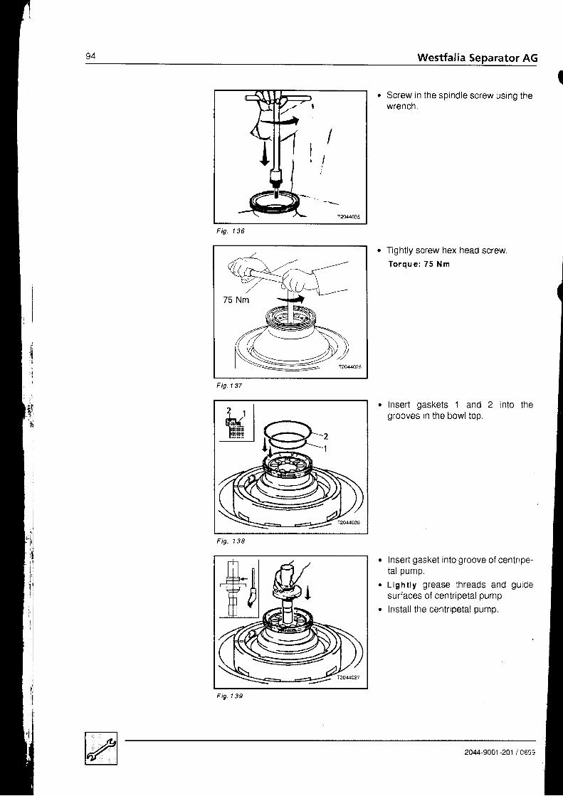
g+ Westfalia Separator AG
. Screw in the spindle screw using thewrencn.
1 3 6Fig
F i g . 1 3 7
fightly screw hex head screw.T o r q u e : 7 5 N m
Insert gaskets 1 and 2 into thegrooves in the bowl top.
Insert gasket into groove of centripe-tal pump.
Light ly grease threads and guidesurfaces of centripetal pump.
Install the centripetal pump
(
I
F ig. 1 3 8
F ig . l 39
ixt:.?' i
2044-9001 -201 / 0699

Westfalia Separator AG
F ig . l 40
F ig .1 4 l
F i g . l 42
r Mount centripetal pump chambercover.
. Watch for proper locationl
. Insert gasket into groove of centrioe-tal pump chamber cover.
. Insert gaskets into grooves of sens_ing-l iquid pump.
. Grease guide surfaces.
. Instal lsensing-t iquid pump
. Fit upper centripetal pumg chambercover.
:
2044-9001-201 / 0699
Fig. 1 43

Westfalia Separator AG
Fig. 144
Grease threads on bowl top and lockring in accordance with the lubrica-t ion o lan ,
Screw on lock ring and tighten it bystr ik ing ( lefr .h and rh read ).
2044-9001 -201 / 0693
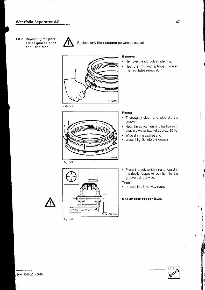
Westfalia Separator AG
4 . 3 . 7 R e p l a c i n g t h e p o l y -a m i d e g a s k e t i n t h ea n n u l a r o i s t o n A
Replace only the dam ased polyamide gasketl
R em ovalo Remove the old polyamide r ing.o Heat the ring with a hot-air blower;
this facilitates removal.
F i t t in g. Thoroughly clean and wipe dry the
groove.r Heat the polyamide ring for five min-
utes in a water bath of approx. 80 "C.
. Wipe dry the gasket ando press it l ightly into the groove.
r Press the polyamide r ing at four dia-metrically opposite points into thegroove using a vice.
Theno press i t in al l the way round.
Use sm ooth copper iaws.
Fig
I
Ir{,lilli'
lDr.l,,so61 -ro' ,ornn
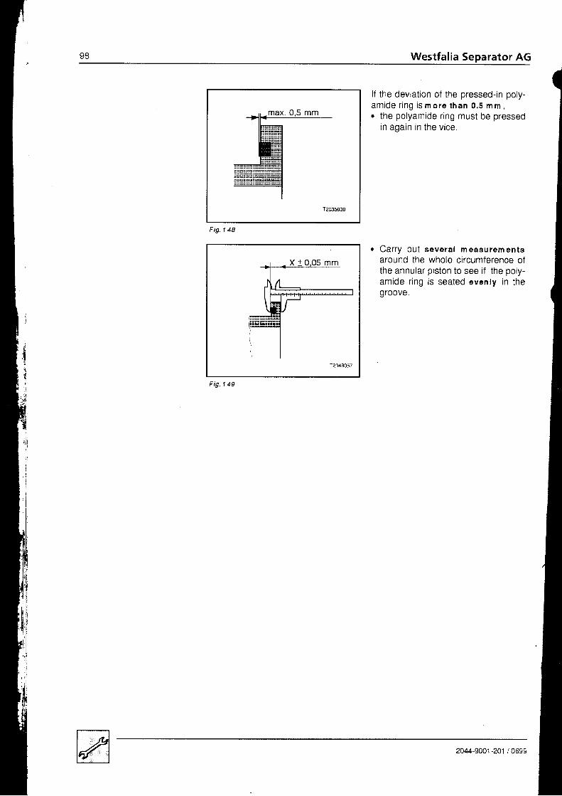
Westfalia Separator AGoa
(
jlf the deviation 0f the pressed-in poly-amide r ing is m ore than 0.5 m m ,. the polyamide ring must be pressed
in again in the vice.
Car ry ou t severa l measurementsaround the whole circumference ofthe annular piston to see i f the poly-amide r ing is seated evenly in thegroove.
Fig. 1 48
Fig. 1 49
2044-9001 -201 / 0699

4 . 3 . 8 R e p l a c i n g t h e p o l y .a m i d e g a s k e t ( b o w ltop )
Fig. 1 50
F ig . l 51
T204805s
F ig .1 52
Rem ova l
o Drive the gasket out of the grooveusing a cyl indr ical pin.
o To do this, insert the cyl indr ical pin al-ternately into the holes provided
F i t t in g
r Heat the gasket in approx. gO oCwater for about 5 minutes.
. Wipe dry the gasket.r Fit the gasket into the clean g roove of
the bowl top (with the narrow sidefacing the bowltop).
o Place on a wooden block and. hammer the gasket evenly into the
groove.
o Press the polyamide ring at four dia-metrically opposite points into thegroove using a vice.
Theno press it in all the way round.
Use smoo th coppe r j aws .
' The sealing surface of the gasketmust not protrude by more than o.sm m from the surface , A,, of the bowltoo.
, I
EEuloxoE
2044-9001-201 /0699
Fig 1 5 3

1 0 0 Westfalia Separator AG
l
{I
.:,.'l:
4 .4 Ve r t i ca l gea r pa r t s
F ig .154
1 Bearing housing2 Gaskets Spherical plain bearing4 Retaining r ing
6 Hex head screw7 Lock washer
8 Sorino assemblv, eottor o"arffiihr.eaded piece
10 Gasket11 Bottom bearing cap12 Worm spindle, compl .14 Neck bearing bridge with cover, compl.
2
8 _
7 ----@
EIF
0 ----d4
g ' - '
1 0 -
2044-9001-201 /0699
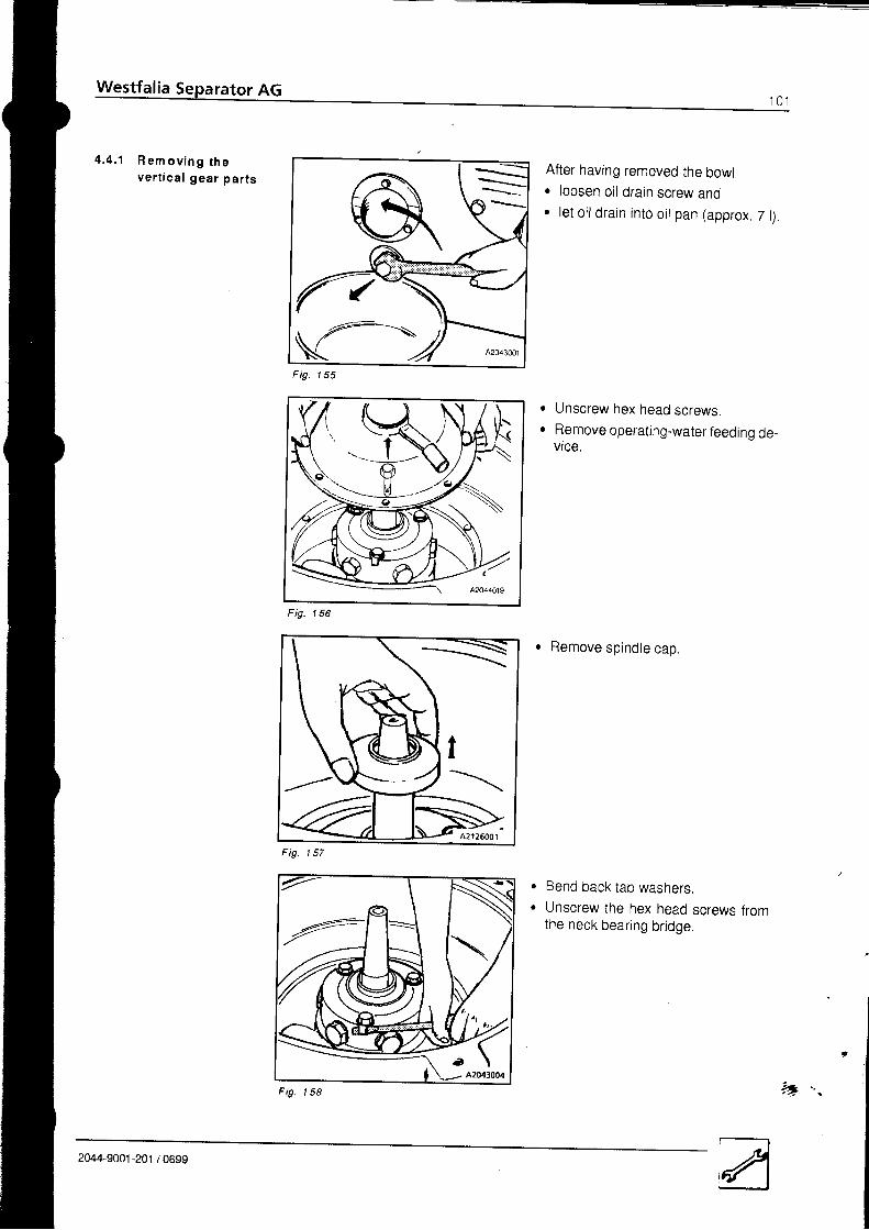
4 . 4 . 1 R e m o v i n g t h eve r t i ca l gea r pa r t s
After having removed the bowlr loosen oil drain screw and. let oi ldrain into oit pan (approx. 7 l)
Unscrew hex head screws.Remove operating-water feeding de-vrce.
e Remove spindle cap
Bend back tab washers,Unscrew the hex head screws fromthe neck bearing bridge.
Fig 1 E E
a
a
1 EAFig
Fig. 1 E 7
a
a
F ig-
9Zx
I
2044-9001-201 /0699
t 5 8-Z -.

t v z Westfalia Separator AG
Remove the neck bearing protectionU q U ,
Take flat gasket 1 out of the neckbearing br idge.
Remove the cylindrical pressurespr ing .
Press the neck bearing assembly oflthe frame using the three fasteningscrews.
Detach the neck bearing bridge frorrthe bal l bearing by l ight ly hammeringon the spindle, andremove it.
a
a
1 5 9Fig
Fig 1 6 0
Fig. 161
F ig.
I
1 6 2
2044-9001 -201 ,'099,
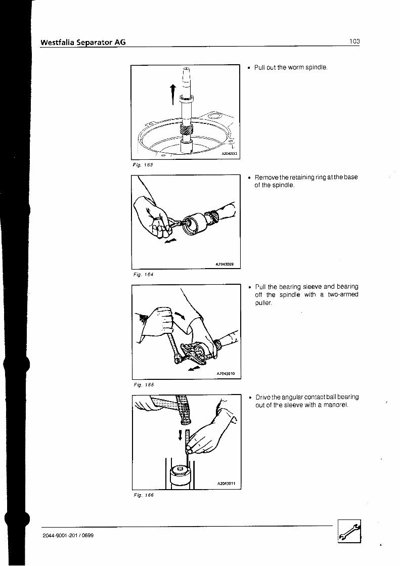
Westfalia
2044-9001-201 /0699
F ig-
. Pul l out the worm spindle
Removethe retaining r ing atthe baseof the spindle.
Pul l the bearing sleeve and bearingoff the soindle with a two-armedpul ler.
Drive the angular contact bal l bearingout of the sleeve with a mandrel .
1 6 3
1 6 4Fig.

'104 Westfalia Separator AG
t
1 6 9F ig.
. Pul l of f bal l bearing protect ion r ing,grooved ball bearing and spacer ring.
. Unscrew the bottom bearing cap.
Take off the bottom bearing cap withgasket.
Unscrew the bottom bearincthreaded piece andremove it together with the spring as-semblv.
o
a
Fig. 167
r
2044-9001 -201 / 0.-

Undo the hex head screws.Force the bearing housing with thespherical plain bearing out of its seatandremove it from below.
Fig. 171
whenever changing the oi l , thoroughty clean the gear chamber with thin-bodiedo i l ,
Carefully remove metal particles from the walls and corners.
Do no t use f lu f fy c lean ing rags (no co t ton waste) !
t
a
4 .4 .2 C lean ing the gea rc h a m b e r
a
a
2044-9001 -201 / 0699
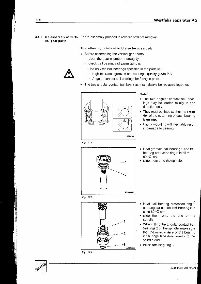
t u o Westfalia Separator AG
4.4.3 Re-assembly of vert i - For re-assembly proceed in reverse order of removalca l gear par ts
T h e f o l l o w i n g p o i n t s s h o u l d a l s o b e o b s e r v e d :
r Before assembling the vertical gear parts,- c lean the gear chamber thoroughly.- check bal l bearings of worm spindle
Use only the ball bearings specified in the parts list:. High-tolerance grooved bal l bearings, qual i ty grade P 6.. Angular contact bal l bearings for f i t t ing in pairs.
. The two angular contact ball bearings must always be replaced together
Note !. The two angular contact ball bear-
ings may be loaded axial ly in onedirect ion only.
. They must be f itted so that the sm allr im of the outer r ing of each bearingis on top .
. Faulty mounting wi l l inevi tably resultin damage to bearing.
Heat grooved bal l bearing 1 and bal lbearing protection ring 2 in oil to80 oC, andsl ide them onto the soindle.
Heat ball bearing protection ring :
and angular contact ball bearing 2 r'o i l to 80 oC andsl ide them onto the end of thesp ind le .When fitting the angular contact babearings 2 on the spindle, make suretha t the nar row r ims o f the bear i rginner r ings face downwards to t f 'espindle end.Insert retaining r ing 3.
F ig . 173
: i rI t v lI t ( - ) lI l l - r - t
Fig. 172
Fig. 174
2044-9001-201 /06!A

wgat_J-'o,*oo,
F i g . 1 7 5
. Heat sleeve 1 in oil to 80 oC ando sl ide i t over the angular contact bal l
oeai lng.
The worm spindle with mounted bal lbearing protect ion r ing. angular con-tact ball bearings and fitted bearingsleeve must- be able to be fitted into the spheri-
cal plain bearing 1 without str ik ingthe upper spindle end,
- be able to be moved axially byhand.
Watch for correct positioning.
o Assemble the spring assembly:- Fi t cup spr ings 3 on guide bolt 1 as
shown in the adjacent diagram.- Place cyl indr ical pressure spr ings
2 on guide bolt 1 and- compress them with disk 4.- Fi t support ing disk 5 on the gurde
bolt 1 and- secure by means of retaining ring
6 .
Fig. 177
when f i t t ing a new worm spindle, the worm wheel should be replaced at thesame t ime, since this part is no longer in perfect condit ion ei iher and could thuscause premature wear to the new worm spindle.
Before installing the neck bearing bridge, check to be sure that- gaskets are in good condition.- the neck bearing bridge on the grooved ball bearing can be moved axiallylf not, smooth the parts with a very fine emery cloth.
Fig 1 7 6
I2
3456
2044-9001 -201 / 0699

1 0 8 Westfalia Separatbr AG
I
't
22
i ! sddcFig. 178
. Mgunt the neck bear ing br idge:
The upper ball bearing of worm spindle iscontained in pressure ring 1 which is heldby six radially arranged, uniformly distrib-uted springs 4.- Insert pressure ring into neck bear.-
ing bridge 2.The six recesses of the pressure ringface the six holes of the neck bearinobridge.
- Thoroughly grease spring pistons
Insert neck bearing spr ings 4 in the spr ing pistons.
Place on threaded plugs 5.
Screw in the six threaded plugs together with the neck bearing springs andspring pistons into the six threaded holes of the.neck bearing br idge andt ighten.
Befo re f i t t i ng t he ope ra t i ng -wa te rfeed ing sys tem
o C h e c k :- Gasket 1 must be seated in the
groove of the spindle.- The spring must have sufficient
ptay.
iI
I
Fig. 179
2044-9001 -201 I 0691

{ n aWestfalia Separa1or AG _ ,"-
r Ch eck ; '- Spindle niust be spring-tensioned
Whenever fitting the vertical gear partsr check the height of the fitted bowt and. re-adjust it if necessary.
1
S p l n d l c m u s t b es p r i n g . t e n s l o n e d .
F ig . l 80
2044-9001"201 /0699
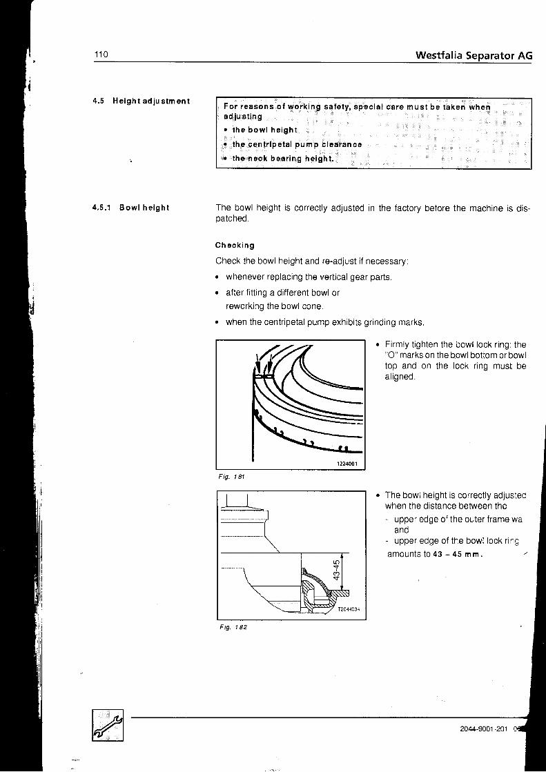
1 1 0 Westfalia Separator AG
4 . 5 H e i g h t a d j u s t m e n t
4 . 5 . 1 B o w l h e i g h t The bowl height is correctly adjusted in the factory before the machine is dis-patched.
G h e c k i n g
Check the bowl height and re-adjust if necessary:
. whenever replacing the vertical gear parts
. after fitting a different bowl orreworking the bowl cone,
. when the centr ipetal pump exhibi ts gr inding marks.
1 8 1Fig.
. Firmly t ighten the bowl lock r ing: the"O" marks on the bowl bottom or bowltop and on the lock ring must beal igned.
The bowl height is correctly adjustecwhen the distance between the- upper edge of the outer frame wa
andupper edge of the bowl lock r ing
a m o u n t s t 0 4 3 - 4 5 m m . /
For reasons o f wo rk ing sa fe t y , spec ia lad j u s t i ng
. t h e b o w l h e i g h t
o t he cen t r i pe ta l pump c lea rance
r t he neck bea r i ng he igh t .
c a r e m u s t b e t a k e n w h e n
Fig 1 8 2
204/�-9001-201

Westfalia Separator AG 1 1 1
1 8 3Fig
Fina l l y
Ad ju stm en t. Unscrew bottom bearing cap 3.. Remove gasket 1.. Adjust the bowl height by turning
bottom bearing threaded piece 2( 1 t u r n = 2 m m ) .Bowl is too low:- Turn the bottom bearing threaded
p iece c lockwise .Bowl is too high:- Turn the bottom bearing threaded
otece an t ic lockwise .
Move the centripetal pump axially toand f ro in the centripetal pumpchamber,Measure the total clearance A (ap-prox. '10 mm).Close the hood,Ch eck :- ls the hood correctly seated on the
frame r im?- Are the hood screws tioht?
Lightly grease the threads of the cen-tr ipetal pump as specif ied in the lu-br icat ion chart .Fi t handle connect ion oiece 1 in thecentr ipetal pump.
Hold the centr ipetal pump withwrench 2.
Screw the handle connect ion oteceinto the centripetal piece as far as itw i l l go ( le f t -hand th read) .
Screw tight bottom bearing cap 3 with fitted gasket 1.
Ensure that the bottom bearing threaded piece 2 does not turn with it
4 .5 .2 Cen t r i pe ta lc l ea ran ce
p u m p
,
a
F ig- 1 8 4
7 A 1Fig
1
2
3
2M4-9001-201 / 0699
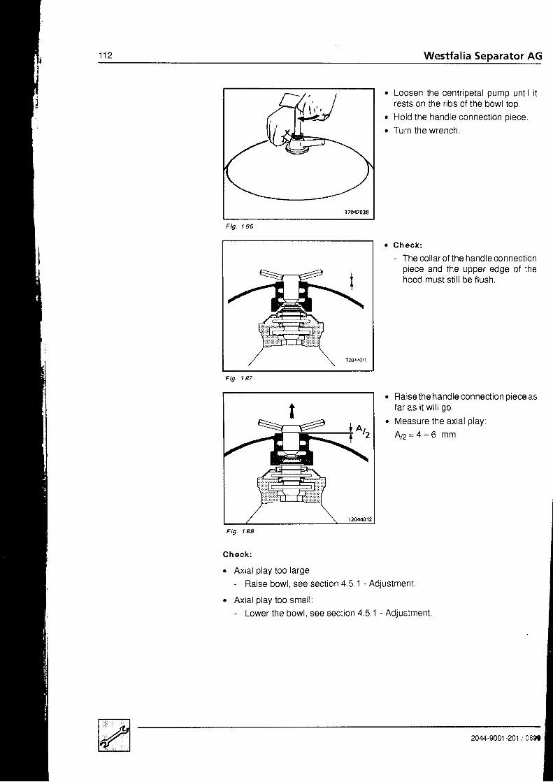
Westfalia Separator AG
Loosen the centripetal pump until itrests on the ribs of the bowl top.Hold the handle connect ion oiece.Turn the wrench.
a
a
1 8 6Fig
Gh eck :- The col lar of the handle connect ion
piece and the upper edge of thehood must st i l l be f lush.
Raise the handle connection oiece asfar as i t wi l l go.
Measure the axial play'
N z = 4 - 6 m m
Fig
1 8 8
C h e c k :
r Axial play too large:- Raise bowl, see section 4.5.1 - Adjustment.
. Axial play too small:- Lower the bowl, see section 4.5 1 - Adjustment
Fig
2044-9001-201 ,'�0:3t
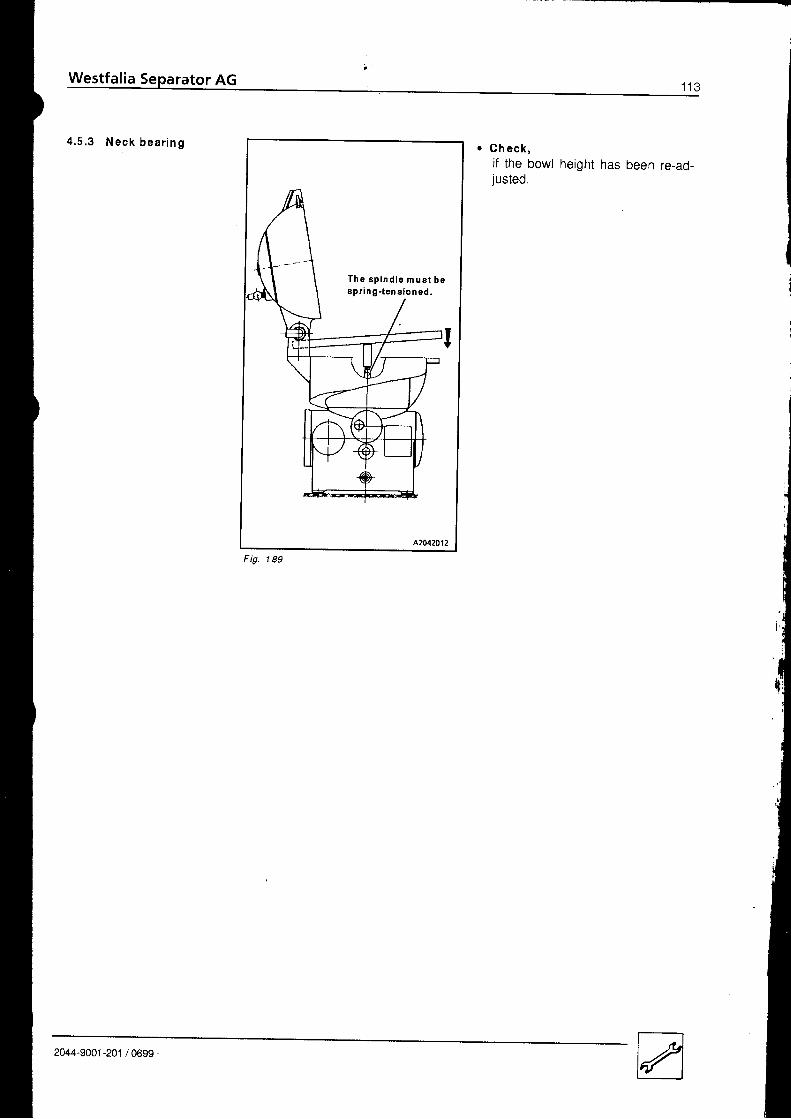
4 . 5 . 3 N e c k b e a r i n g o C h e c k ,if the bowl height has been re-ad-justed.
I
I1
T h e s p i n d l s m u a t b esp r i ng - t ene loned .
1 8 9F ig.
2044-9001-201 /0699
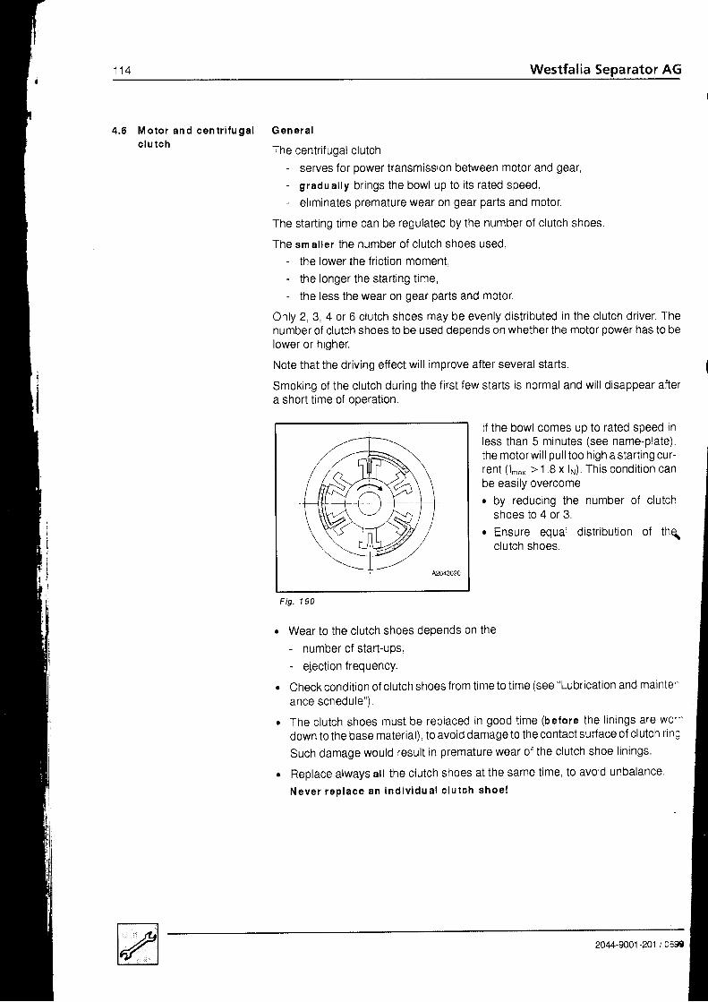
1 1 4 Westfalia Separator AG
4.6 M otor an d cen t r i fu galc l u t ch
G ene ra l
The centrifugal clutch- serves for power transmission between motor and gear,- gradual ly br ings the bowl up t0 i ts rated speed,- eliminates premature wear on gear parts and motor.
The starting time can be regulated by the number of clutch shoes.
The sm al ler the number of c lutch shoes used,- the lower the friction moment,- the longer the start ing t ime,- the less the wear on gear parts and motor.
Only 2,3. 4 or 6 clutch shoes may be evenly distributed in the clutch driver. Thenumber of clutch shoes to be used depends on whether the motor power has to belower or higher.
Note that the driving effect will improve after several starts.
Smoking of the clutch during the first few starts is normal and will disappear aftera short time of ooeratron.
lf the bowl comes up t0 rated speed inless than 5 minutes (see name-plate).the motorwil l pul l too high astart ing cur-rent (1..* > 1 ,8 x lp). This condit ion canbe easily overcome. by reducing the number of clutch
shoes to 4 or 3.o Ensure equal distr ibution of thq
clutch shoes.
I
i
1 9 0F ig.
Wear to the clutch shoes depends on the- number of start-ups,- ejection frequency.
Check condition of clutch Shoes from time to time (See "Lubrication and mainte--ance schedule")
The clutch shoes must be replaced in good t ime (before the l in ings are w0. 'down to the base material), to avoid damage to the contact surf ace ol clutch rin;
such damage would result in premature wear of the clutch shoe linings.
Replace always all the clutch Shoes at the Same time, to avoid unbalance,
N e v e r r e p l a c e a n i n d i v i d u a l c l u t c h s h o e !
2044-9001 -201 / Oetr

Westfalia Separator AG 1 1 5
4 . 6 . 1 R e m o v i n g t h e m o t o r Disconnect the motor and suspend itin a suitable hoist.Unscrew the hexagon nuts on the in-termediate flange.Remove the lock washers,
Remove the motor together with theclutch driver.Remove the clutch shoes (see4.6 .4) .
Unscrew the hex head screw on theclutch driver.Pull the clutch driver off the shaft endusing the pul l ing device.
1 9 1Fig
Fig. 192
Fig. 193
//t rIi
A2043021
2044-9001 -201 / 0699
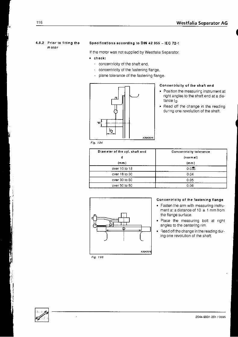
t r o Westfalia Separator AG
4 .6 .2 P r i o r t o f i t t i ng t hem o lo r
Spec i f i ca t i ons acco rd ing to D IN 42 955 - lEC 72 -1
lf the motor was not supplied by Westfalia Separator,r c h e c k r
- concentricity of the shaft end,- concentricity of the fastening flange,- plane tolerance of the fastening flange.
42042015
Fig. 194
Concent r i c i t y o f the shaf t end. Position the measuring instrument al
right angles to the shaft end at a dis-tance 172.
r Read off the change in the readingduring one revolut ion of the shaft .
Concen t r i c i t y o f t he f as ten ing f l ange
. Fasten the arm with measuring instru-ment at a distance of 10 * 1 mm fromthe f lange surface.
. Place the measuring bolt at r ightangles to the centering rim.
o Read off the change in the reading dur-ing one revolution of the shaft.
(
1 9 5Fig
D i a m e t e r o f t h e c y l . s h a f t e n d
d
( m m )
C o n c e n t r i c i t y t o l e r a n c e
( n o r m a l )
( m m )
over 10 to 18 0.035over 18 to 30 0.04
over 30 to 50 0.05over 50 to B0 0 .06
2044-9001 -201 / 0699

Westfalia Separator AG 117
1 9 6
Plane to le rance o f t he f as ten ingf l an ge
. Fasten the arm with measuring instru-ment at a distance of 10 + 1 mm fromthe flange surface.
. Place the measuring bolt at r ightangles on the flange surface.
. Read off the change in the reading dur-ing one revolution of the shaft.
. Displace the measuring instrumentth rough 1 80 ' .
. Repeat the measurement.
. Determine the mean value of bothmeasurements.
in the reverse order of removal and according 6 tne4 . 6 . 3 F i t t i n g t h e m o t o r For fitting the motor proceed
instructions in 4.6.6.
I
F a s t e n i n g f l a n g eCenter in g d iam e ter
D
( m m )
C o n c e n t r i c i t y a n d p l a n e t o l e r a n c e
(n orm a l )
( m m )
over 1 00 to 230 0 . 1over 230 to 450 0.125
2044-9001-201 /0699

Westfalia Separator AG1 1 8
t4 . 6 . 4 R e m o v i n g t h e c l u t c h
s h o e sa
o
Unscrew hex head screws 1.Remove the brake housino
Unscrew the hex head screw out ofthe clutch driver using a socketwrench andslide the ring towards the drive side.
Pull clutchdrive side.
shoes out towards the
Fig. 197
1 9 8F ig-
-ur'\ --0
\ffiffiFig. 199
2044-9001 -201 / 0t39

o4 .6 .5 F i t t i ng t he c lu t ch
sh oeso Fit the clutch shoes - equally distrib-
uted - (3 or 4 or 6), into the slits of theclutch driver so that they will bepushed by the driver and not pulled.
N ote:r Ensure that the clutch shoes fit
loosely in the slits of the clutch driver.
Slide ring 1 onto the clutch driver asfar as i t wi l l go andsecure it with hex head screw 2.Screw on the brake houslnq.
In the event of unusual noises occurr ingin the centrifugal clutch during start-up,. Apply a water. thin layer of paste to
pressure surfaces a (see 4.2.3 - Lu_brication chart).
lf the Iubricant layer is too thick, someof the paste can get onto the friction sur-face and cause clutch slippage.
Fig.
A20rt4009
A2044010
a
a
Fig.
F ig.
2044-9001-201 /0699

t z v Westfalia Separator AG
I
I
4 .6 .6 F i t t i ng t he c lu t chd r i ver
The motor power is transmitted to the worm wheel shaft of the separator via a cen-trifugal clutch
To ensure proper functioning of the centrifugal clutch, the clutch driver must befitted and fastened so on the motor shaft end, that after mounting the motor theclutch shoes abut with their whole surface on the clutch drum.
: 1
Distance of clutch driver to clutch drum
C h e c k :
L 2 > L l
L 2 = L l + a p p r o x . 5 m m
Fig
To fasten the clutch drrver on the motorshaftr firm ly tighten the screw head of the
hex head screw with trunion aoainstthe contact surface.
E = M 1 0d = 7 m m
F i g . 2 0 4
\. Fi t t ing the clutch shoes: see 4.6.5.
r For connecting the motor proceed according to the instructions in 4.6.3.
. Check direction of rotation. speed and starting time of the bov11l (see 4.1 .4 ar:4 . 1 . 5 )
2044-9001 -201 / 0439
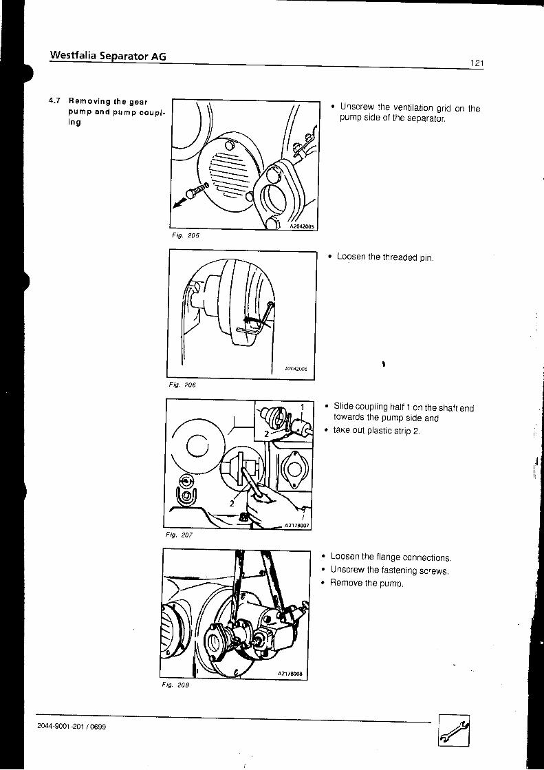
S
4 . 7 R e m o v i n g t h e g e a rp u m p a n d p u m p c o u p l .i n g
o Unscrew the ventilation grid on thepump side of the seoarator.
. Loosen the threaded oin.
Sl ide coupl ing hatf 1 on the shaft endtowards the pump side andtake out plastic strip 2.
. Loosen the flange connectionso Unscrew the fastening screws.. Remove the pumo
Fig.
II
i l' l
I
2044-9001-201 /0699

t z z Westfalia Separator AG
4 .8 Ho r i zon ta l gea r pa r t s
l')(\.1
c\l
C\I
(oN
-$C\I
C\J
(.)AI
Fig. 209

Westfal ia Separator AG i^^
4.8.1 R em ovin g th e wormwh eel
Fig. 21 0
Fig. 21 3
Remove the gear pump and pumpcoupling (see 4.7).Loosen oil drain screwLet oil drain into oil oan
Unscrew hex head screws from rev-olut ion indicator housino.
a
Remove revolution Indicator hous-I ng .
Unscrew the hexwasher.
neao screw and
a
a
2 1 1Fig
Il ,
Fig 21 2
ti
2044-9001-201 /0699

124 Westfalia Separator AG
(
F ig .21 4
o Pul l the coupl ing hatf with f langed fanpaddle off the shaft end of the wormwheelshaft .
Tool: Pul ler
. Take the fan paddle out of the frame
r Unscrew the col lar nut withtsocket wrench; while doing so
o hold the worm wheel to preventworm wheel shaft f rom turnino.
Unscrew the hex head screws on thebearing cover.Force the bearing cover off thecentering rim using three screws(DlN 933 - M 10x50) andtake it out together with the bail bear-ing and gasket. ,
I
Fig 21 5
tne
the
21 6Fig
Fig. 21 7
2044-9001 -201 / 0699

Pullthe ball bearing protection r ing 1off the shaft.Unscrew the hex head screws fromthe worm wheel; while doing sohold the clutch drum to prevent theworm wheel shaft from turning.Force the worm wheel off the cone ofthe worm wheelshaft andremove it,
21 IFig
4.8.2 Be fo re a l ong - te rmsh u t - down o f t h esep ara to r
Drain the lubricating oi,.Fi l l gear chamber with corrosion-preventing oi l , e. g, sHELL Ensis oi l 30.Oil level must be up to middte of sight gtass.Let the separator run for approx. 1 0 minutes with ou t b o wl to ensure that al l gearparts are splashed with corrosion-preventing oilDrain protective oil.
special measures for removing the corrosion-preventing oil need not be takenBefore re-starting the machine, fill the gear chamber with the specified lube oil(see lube oil table) up to the upper third of the sight gtassStore the greased bowl in a dry place.
2044-9001-201 / 0699

t z o Westfalia Separator AG
4 .8 .3 F i t t i ng t he wo rmwhee l
When fitting the worm wheel. proceed in reverse order of removal (4.8.1),
l m p o r t a n t h i n t s
r Oilthe conical oart of the worm wheel and. wipe it clean and dry with a cloth.
o Carefully clean the hub of the worm wheel.
42044017
Fig, 21 I
12J
4
Worm wheelWorm wheel shaftRingAngular contact ball bearing
5 Collar nut6 Gasket7 Bearing cover8 Bearing cover
a
a
r The worm wheel 1 must be clamped onto the worm wheel shaft 2 by tighteningthe hex head screws in the worm wheel evenly and alternately with a torquewrencn.T o r q u e : 4 4 N m
. When the toothed r im is worn:- Always replace worm wheel 1 and the worm spindle together.
Sl ide r ing 3 onto worm wheel shaft 2.
Mount on worm wheel shaft:- large bearing cover 7 with gasket 6.- angular contact bal l bearing 4,- screwed-on small bearing cover B.
Watch for correct positioning of the large bearing cover 7!
Remove the smal l bearingcover 8.
Screw collar nut 5 tightly to the shaft end using a socket wrench
Screw on the smal l bearing cover again.
Fi l l gear chamber in accordance with chapte( 4.2.2.
a
a
a
a
a
2044-9001 -201 / 0699

Westfalia Separator AG 1 2 7
During running-in of the gear parts the gear pump must not run.Before switching on the motor. check that the plastic strip has not been insertedin the pump coup l ing .
Check direct ion of rotat ion of bowl (4.1.4).
Check spindle speed with a hand tachometer (4.1 .5)
To run in new gear parts, let the separator run for approx, one hour wirhoutb o w l .
Whi le running in the gear parts, switch the motor on and off several trmes.
After running-in the gear parts:- Instal l the bowl.- Adjust the bowl height (see 4.5.1).
2044-9001 -201 / 0699

Westfalia Separator AG
4 . 9 R e m o v i n g t h e c l u t c hd r u m a n d w o r m w h e e lsha f t
Remove the motor (see 4 6.1).
Remove the gear pump and pump coupling (see 4.7).
a
a
F ig.
F ig. 221
Fig.222
Unscrew hex head screws 1.Remove the brake housino,
Unscrew the Allen screw with asocket wrench.While doing so- block the clutch pul ley on the pump
side with a screwdriverto orevent the worm wheel shaftfrom turning.
Rdmove the fan-type lock washerand center ing disk.
Force the clutch drum otf the shaflend using the pul l ing device.
a
t
-(^
2044-9001-201 /0699

Westfalia Separator AG t < J
z z JFig
Remove the clutch drum from theshaft end of the worm wheel shaftusing the mounting tool and with theaid of a crane.Dismantle worm wheel (see 4.8.1).
Unscrew the hex head screws in thebearing cover.Force off the bearing cover by meansof hex head screws andtake it off together with the sealingring and gasket.
t
Lightly hammer on a hard woodenblock to drive out the worm wheelshaft together with ring and ball bear-ing towards the pump side
Carefully take the worm wheel shaftout of the frame.
F i g . 2 2 4
*
H]
2044-9001-201 /0699
F ig. 226

1 3 0 Westfalia Separator AG
I4 .9 .1 l ns ta l l a t i on o f t he
worm whee l sha f ta n d t h e c l u t c h d r u m
4 .9 .2 I ns ta l l a t i on o f t hes e a l i n g r i n g s
. The Allen screw has to be tightenedby means of a torque wrench.T o r q u e : 1 5 0 N m
For re-installation proceed in reverse order of removal,
Pay spec ia l a t ten t ion to the fo l low ing l
o The conical part of the shaft has to be cleaned and wiped dry with a smooth ragano
o the inside of the clutch hub is to be cleaned as well to assure proper fitting.
F ig. 227
a
a
Lubricate the sealing surfaces of the shaft sealing rings with oit ; never usegrease!
sealing rings which have dried out or hardened as a result of a long storage timecan be immersed in hot oil (70 "C) for about 20 minutes before fitting.
Do not damage sealing surfaces.
Insert shaft seal ing r ings.The inscribed side must face towards the serviceman.
The sealing lips of the shaft sealing rings must not grip the shaft too tighily.
I t must be possible to turn the shaft easi ly by hand.
2044-9001 -201 / 0699
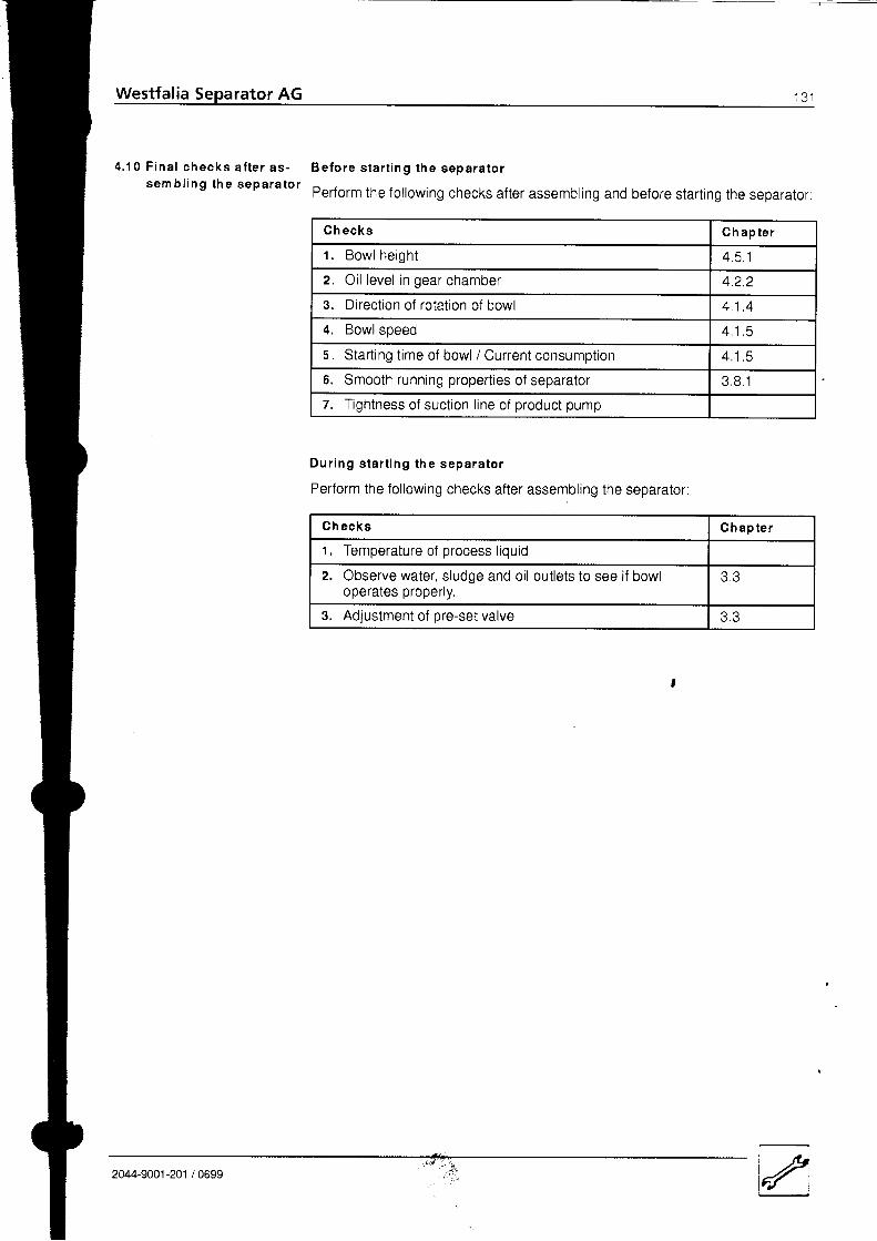
Westfalia Separator AG ; J i
4 . 1 0 F i n a l c h e c k s a f t e r a s -s e m b l i n g t h e s e p a r a t o r
Be fo re s ta r t i ng t he sepa ra to r
Perform the following checks after assembling and before starting the separator:
D u r i n g s t a r t i n g t h e s e p a r a t o r
Perform the following checks after assembling the separator:
Ch ecks C h a p t e r
1. Bowl he igh t 4 5 . 1
z. Oi l level in gear chamber 4 .2 .2
3. Direction of rotation of bowl + . t . +
4. Bowl speed 4 1 , 5
5. Start ing t ime of bowl / Current consumption 4 . 1 . 5
5. Smooth running propert ies of separator 3 8 . 1
7. Tightness of suct ion l ine of product pump
Ch ecks Ch ap te r
1. Temperature of process liquid
z. Observe water, sludge and oil outlets to see if bowloperates properly.
J , J
3. Adjustment of pre-set valve
". .;i.L2044-9001-201 /0699
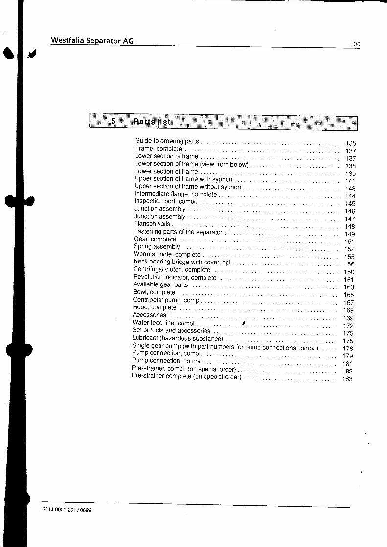
Guide to ordering partsFrame, completeLower section of frameLower section of frame (view from below)Lower section of frameUpper sect ion of f rame with syphonUpper section of frame without syphonlntermediate flange completeInspection port, compl.Junction assemblyJunction assemblyFlansch vollst.Fastening parts of the separato( . . . . .Gear, complete . .Spring assembtyWorm spindle, completeNeck bearing bridge with cover cpl.Centrif ugal clutch. compteteRevol ution indicator, completeAvailable gear partsB o w l , c o m p l e t e . . .Centr ipetal pump compl.H o o d , c o m p l e t e . . .AccessoriesW a t e r f e e d l i n e , c o m p l . . . . . . . . t , . . .Set of tools and accessoriesLubricant (hazardous substance)Single gear pump (with part numbers forpump connections compl.)Pump connect ion, compl.Pump connect ion, compr.
l e t r
1 a 7
t J d
t + l
1 A a
144145t 4 b
1 4 7t + o1491 5 11521 q q
t c o
1 6 01 6 1
t b c
1 6 9
1 7 2t t c
175t / o' t 70
1 8 1182t o J
Pre-strainer, compl. (on special order)Pre-strainer complete (on special order)
2044-9001-201 /0699
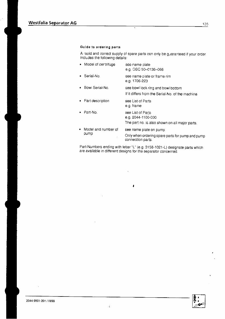
Westfalia
G u i d e t o o r d e r i n g p a r t s
A rapid and correct supply of spare parts can only be guaranteed if your orderincludes the fol lowing detai ls:. Model of centrifuge see name plate
e.g. OSC 50-0136-066
see name plate or frame r ime.g.1706-223
see bowl lock ring and bowl bottom
lf it differs from the Serial-No. of the machine.
see List of Partse.g. f rame
see List of Parjse.g. 2044-1100-000The part no. is also shown on all major parts
see name plate on pump
Onlywhen ordering spare parts for pump and pumpconnection oarts.
o Serial-No.
. Bowl Serial-No.
o Part description
o Part-No.
o Model and number ofpump
Part-Numbers ending with let ter "L' (e.9. 3158-102i -L) designate parts whichare available in different designs for the separator concerned.
2044-9001-201 /0699

Westfalia Separator AG
I
i
8
9
1 1
1 0
1 9
20
20441100{10 1
CU
52
c l
33
37
36
38
2044-9001 -201 / 0699
Fi9. 228

Westfal ia Separator AG j�37
Par t desc r i p t i on D i m e n s i o n s
17
I
1 01 1I Z
I J
1 3 . 11 3 . 21 e e
1 a A
1 41 5t o
1 71 81 0
20222,5
34e R
37QC
qn
5 152
2 0 4 4 - 1 1 0 0 - L
2179-1001-010see page 1442179-1 085-000001 9-6966-1 502178-1 085-000001 9-6933-3002179-1 038-0002179-1031-0002179-1 039-0000026-1 086-0300021-2843-9800026-1 262-5500006-4234-1 600021-3527-0000019-6935-3000019-8910-0300007-1 796-5500004-21 99-7500001 -0028-800
2179-1124-000001 9-6845-300see page 1450004-5457-780001 9-6971 -1 500001 -0146-000
0019-6972- '15000'13-0280-3002044-1 21 9-0000007-2571-7500019-6901-300
'1
11
1
1111z
U
1'1
't
111'1
11a
1z
a
116
Fram e , com p le te
Lower sec t i on o f f r ameIntermediate flange, completeVentilating plateHex head screw ISO 4017Ventilation gridHex head screw ISO 4017Brake housingBrake bolt. comolete
- Brake bolt- Cyl indr ical pin tSO 2338- Brake l in ing- Rivet DIN 661
Cylindrical pressure springTapered handle DIN 99Hex head screw ISO 4017Screw p lug DIN 910Gasket DIN 7603GasketSight glassFlangeHex head screw tSO 4017Inspection port, compl.GasketHex head screw ISO 4017Welded flangeHex head screw ISO 4017Hexagon nut tSO 4032Operatin!-water feedi ng deviceGasket 'Hex head screw ISO 4017
M12x20
M10x20
52-80x122x1,5M 1 2x3511/z inM12x40M 1 2
297x4M 8 x 1 6
B-6x1440x148,8x84x1246x5,5x95-5,5Wdg.
M 1 2 5M10x25G3/4A427x3255x75x280-70
M6x25
2044-900t-201 /0699

20441100-01G2
Fig. 229
P os . P a r t - N o . Q ty . Pa r t desc r i p t i on D i m e n s i o n s
58
OU
o l
2179-1120-000001 9-6901 -3002179-1120-0.10001 9-6839-300
1/1
IC l
. 5
Lower sec t i on o f f r ame ( v i ew f rombe low)
CoverHex head screw ISO 40.17CoverHex head screw ISO 4017
M8x16
M6x10
2044-9001 -201 / 0Ee3

Westfalia Separator AG I J Y
71
1 ^
75
2044 1100{00.1
F ig .23o
Pos . P a r t - N o . Q ty ' P a r t d e s c r i p t i o n D i m e n s i o n s
7i
7172737475
0019-6841-3000021 -3038-000
0026-1 744-1602169-3323-0000026-1 402-0300019-6907- '150
411111
Lower sec t ion o f f ram e
Hex head screw ISO 4017Paddle
feather keyClutch half (separator)DiskHex head screw ISO 4017
M6x16298x8A6x6x35
8.2x30x3M8x30
2044-9001-201 /0699

140 Westfalia Separator AG
I
30
26
27 l
II
48
47
49
25
3
2
54
53
56
41
40.1
42
40.4
44
40.2
40.5 ----€-
*oX'20441100{1c3
Yt-v!4 si,[-^
2044-9001 -201 I 0699
Fig. 231
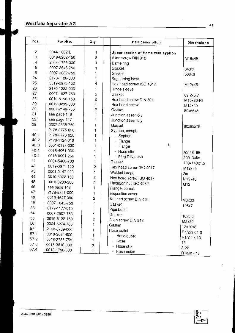
P a r t - N o . P a r t d e s c r i p t i o n D i m e n s i o n s
z
45
24252627282930a l
.tz
40.140,24 0 . 340.44 0 . 541+z
434445+o
474849A E
546 6
56575 7 . 15 7 . 25 7 . 357.4
2044-1002-L001 9-6202-1 502044-1 795-0000007-2548-7500007-3032-7502170-1 1 26-000001 9-6973-1 502170-1222-0000007-1 937-750001 9-51 96-1 50001 9-0235-3000007-2148-750see page 146see page 1470007-2335-7502178-2775-02A2178-2776-0202178-1124-0100001 -01 88-0300018-4061-3000018-0991-2600004-5460-7800019-6971- '1500001 -0147-000
001 9-6972-1 500013-0280-300see page 14821 78-8851-000001 9-4547-0900007-1 845-7502179-1177-0100007-2507-7500019-61 22-1500004-5274-78021 68-8769-000001 8-3064-600001 8-2786-75800'18-3816-300001 8-1 796-600
1
11114152A
z
11.1'1'1
1111'1
a
1z
a
11Z
1'1
1z
1'1
1'1
z
1
GasketHex head screw ISO 4017Welded flangeHex head screw ISO 4017Hexagon nut tSO 4032Flange compt.Inspection coverKnurled screw DIN 464GasketPipe bend
U p p e r s e c t i o n o f f r a m e w i t h s y p h o nAllen screw DIN 912Baffle ringGasketGasketSupport ing baseHex head screw ISO 4017Hinge sleeveGasketHex head screw DIN 561Hex head screwGasketJunction assemblyJunction assemblyGasketSyphon, compl.
- Syphon- Flange- Flange I
- Hose cl ip- Plug DIN 2950
M16x45
640x4568x6
M12x45
69,2x5,7M 10x30-RlM12x5050x66x8
80x95x1 5
AS 48-95290-3l4in100x140x1 5M12x352inM12x40M 1 2
M8x30I U b X /
16x3.5MBx201 2x1 9x3R1/2in x 1 0R1/2 in x 101 3B-22R' l /2in - 13
2044-9001-201 /0699

6
4
5
28
24
30
26
27
Westfalia Se rator AG
48
47
49
40.2
43
40.4-.-___.-
+a
{kv{,i;
Fig. 232
2044-9001 -201

Pos . P a r t -N o . Q ty . Pa r t desc r i p t i on D i m e n s i o n s
z
345o
242510
272829303 1JZ
40.240.4434446A 7
46
49tre
5455
57.15 7 . 257.357.4
2044-1002-L
001 9-6202-1 502044-1 795-0000007-2548-7500007-3032-7502170-1 1 26-0000019-6973- '1502170-1222-0000007-1937-750001 9-51 96-1 50001 9-0235-3000007-2148-750see page 146see page 1470007-2335-7502178-1124-0100018-4061-3000001 -01 88-030001 9-6971 -1 50see page 14821 78-8851 -000
00'19-4547-0900007-1845-7502179-1177-0100007-2507-750001 9-61 22-1500004-5274-78021 68-8769-000001 8-3064-600001 8-2786-7580018-3816-300001 8-1 796-600
811114'1
5z
4z
11111121'1
z"1
11z
111121
l U p p e r s e c t i o n o f f r a m e w i r h o u t
I s y p h o n
lA l len screw DIN 912
I Baffle ring
lGasketlGasketlSupporting base
I Hex head screw ISO 4017
I HinOe sleeve
lGasketlHex head screw DIN 561
I Hex head screwGasketJunction assemblyJunction assemblyGasketFlangeHose cl ipFlange '
Hex head screw ISO 4017Flange compl.Inspection coverKnurled screw DIN 464GasketPipe bendGasketAllen screw DIN 912GasketHose outlet
- Hose outlet- Hose- Hose cl ip- Hose outlet
M16x45
640x4568x6
M12x45
69,2x5,7M10x30-RlM12x5050x66x8
80x95x1 5
AS48-9s
M12x35
M8x301 06x7
16x3.5V8x201 2x1 9x3l1 /2 in x 1 01 1 / 2 i n x 1 01 3)-22l '1/2in - 13
.l
2044-9001-201 /0699
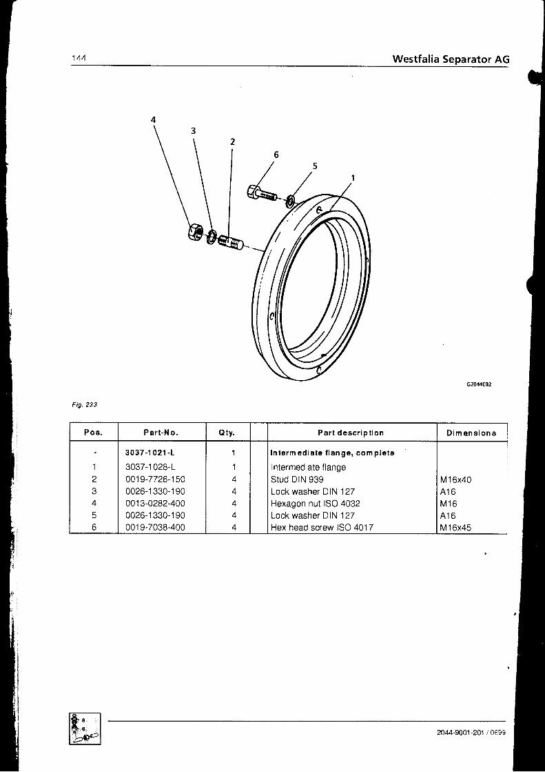
144 Westfalia Separator AG
Fig. 233
Pos . Pa r t -No . Q ty . P a r t d e s c r i p t i o n D i m e n s i o n s
1z
A
q
3037-1 021.1
3037-1 028-L0019-7726-15Q0026-1 330-1 90001 3-0282-4000026-1330- '190001 9-7038-400
1
1
4
4
In term ed ia te f lange, com p le te
Intermediate flangeStud DIN 939Lock washer DIN 127Hexagon nut ISO 4032Lock washer DIN 127Hex head screw ISO 4017
M16x40A 1 6M 1 6A 1 6M16x45
2044-9001 -201 t 0t9?

Fig.234
{iI
P os . P ar t -N o. Qty. Pa r t desc r i p t i on D i m e n s i o n s
12a
456
2178-1045 -0 20
2178-1047-0002178-1160-0000026-1 556-1 502178-1124-0200001 -01 82-0300018-3817-300
1I
11111
I nspec t i on po r t , com p l .
Inspection port, compl.FlapNotched pin ISO 8740FlangeFlangeHose c l ip DIN 3017
4x25
AL50-70
2044-9001 -201 / 0699

146 Westfalia Separator AG
2169 280s{60
Fig. 235
P os . P ar t -N o. oty . P a r t d e s c r i p t i o n D i m e n s i o n s
1
1 1
l dt . z
' l A
1 R
l . o
1 7
1 . 8a
A
o
21 69-280s .060
21 69-2832-01 02169-2831-0202169-2831-0300018-4845-750001 8-4845-01 00018-4845-0202178-1 1 08-000001 3-0291 -300
001 8-0990-2600004-2216-780001 8-1 394-500001 9-6973-1 500013-0280-3000001 -0772-000
1
11'l
1112t1
'1
21B81
J u n c t i o n a s s e m b l y
Expansion joint , compl- Expansion joint- Expansion joint- Gasket- Gasket holder- Clamp, compl.- Plate- Hexagon nut DIN 985- P lug DIN 2950
Gasket DIN 2690Straight-way valveHex head screw ISO 4017Hexagon nut ISO 4032Flange DIN 2631
M 8290-1l2in50PN6
M 1 2x45M 1 250x60,3
1
c92044-9001 -201

r .6
rl1 . 8
4
.4-.,\,/ "
1 . 5
2
F ig .236
2169 2805 070
Pos . Pa r t -N o . Qty. Pa r t desc r i p t i on D i m e n s i o n s
I
t . l
t . z
1 . 41 ^
1 ' 7
1 . 8z
\,4
21 69-2805-070
2169-2832-0102169-2831-0202169-2831-030001 8-4845-7500018-4845-0'10001 8-4845-0202178-1 1 08-0000013-0291-3000018-0990-2600004-2216-7800001-0772-000001 9-6973-1 50001 3-0280-300
1
1111114.
111/1
l J u n c t i o n a s s e m b l yt -I txpanslon Jornt, compl
- Expansion joint- Expansion joint- Gasket- Gasket holder- Clamp, compl.- Plate- Hexagon nut DIN 985- P lug DIN 2950
Gasket DIN 2690Flange DIN 2631Hex head screw ISO 4017Hexagon nut ISO 4092
M 8290-1/2in50PN650x60,3M12x45M 1 2
2044-9001-201 /0699
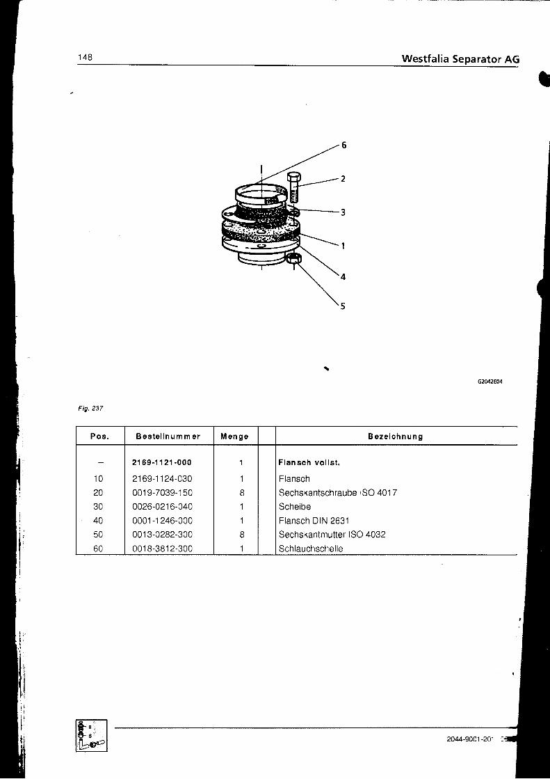
14s Westfalia Separator AG
B e z e i c h n u n g
Flansch vo l l s t .
Flansch
Sechskantschraube ISO 401 7
Scheibe
Flansch DIN 2631
Sechskantmutter ISO 4032
Schlauchschel le
B e s t e l l n u m m e r
1 0
20
40
50
60
2169-1121 -000
2169-1 '124-030
001 9-7039- 1 50
0026-021 6-040
0001 -1 246-000
001 3-0282-300
0018-3812-300
2044-9001-201

Westfal ia Separator AG 1^e
,a
4
3
2
1
7
Fig. 238
6
5
P os . Pa r t -N o . Qty. P a r t d e s c r i p t i o n
1
z
4q
6
as per order
0026-2129-030
0021-303't-750
0026-21 30-030
0006-4402-01 0
001 3-0284-300
2251 -1 003-000
4
+
4
+
1 2
8
1
Fas ten ing pa r t s o f t he sepa ra to r
Anchor boltcapRubber cushionvdv
Cup spring DIN 2093
Hexagon nut ISO 4032
Foundation frame(on special order only)
2044-9001-201 /0699
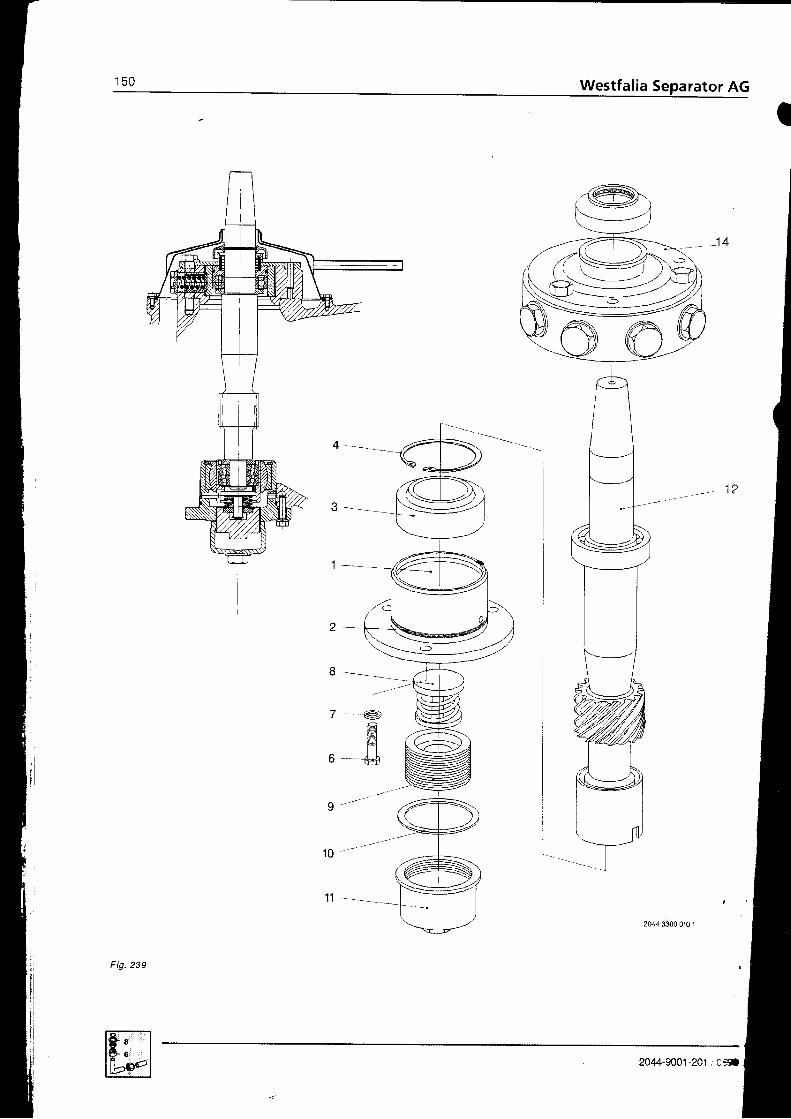
rator AG
I
- - s '
2
8
7
b
I
1 o "
l ll l _ -
2044-330&01G1
F ig .239
2044-9001 -201 ,'C*a

P os . P a r t -N o . Q ty . P a r t d e s c r i p t i o n D i m e n s i o n s
1z
4
-7
8
1 01 11 21 4
2044-3300-01 0
21 79-3136-0000007-2379-7500011-8071-0000026-5845-1 70001 9-6973-1 500026-1 328-1 90see page 152 '00'10-7202-0000004-531 6-780001 0-8003-230see page 155see page 156
1
11'1
1
111111
G ea r , com p le te
Bearing housing compl.GasketSpherical plain bearingRetaining r ing DIN 472Hex head screw ISO 4017Lock washer DIN 127Spring assembtyBottom bearing threaded pieceGasketBottom bearing capWorm spindle, compteteNeck bearing bridge with cover, cpl.
129x4GEsOES120x4M12x45412
80x95x1,5
2044-9001-201 /0699
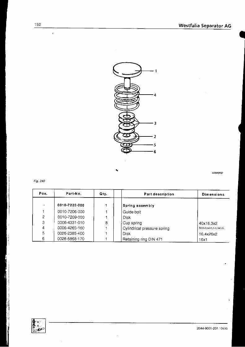
t c z Westfalia Separator AG
Fig. 240
l
iI
,lPos , Pa r t -N o . oty. Par t desc r i p t i on D i m e n s i o n s
1z
A
56
001 0 -7220 -000
001 0-7206-000001 0-7209-0000006-4331-0'100006-4265-1 600026-2385-4000026-5868-1 70
1
118111
S p r i n g a s s e m b l y
Guide boltDiskCup springCyl indr ical pressure spr ingDiskRetaininq r ing DIN 471
40x16,3x250.6x3,6x91,3-4,5WDG
16,4x26x21 6xl
2044-9001 -201 ,/ 0693

1 E.A Westfalia Separator AG
(
l
Fig. 241
ffi 2044-9001 -201 . C:30
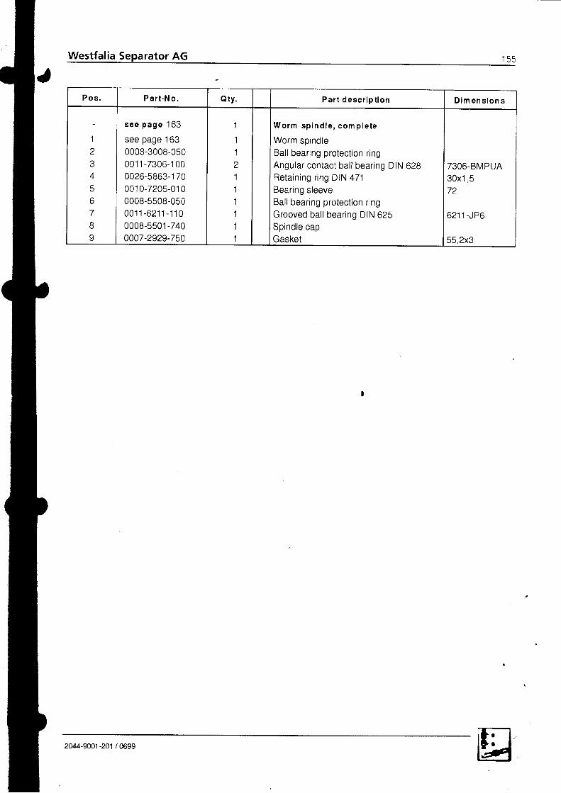
P o s . Pa r t -N o . Qty. P a r t d e s g r i p t i o n D i m e n s i o n s
'1
z
45
789
s e e p a g e 1 6 3
see page 1630008-3008-050001 1 -7306-1 000026-5863- '170001 0-7205-01 00008-5508-0500 0 1 1 - 6 2 1 1 - 1 1 00008-5501 -740
0007-2929-750
I
1'1
z'1
11111
W o r m s p i n d l e , c o m p l e t e
Worm soindleBal l bearing protect ion r ingAngular contact bal l bearing DIN 628Retaining r ing DIN 471Bearing sleeveBall bearing protection ringGrooved bal l bearing DIN 625Spindle capGasket
7306-BMPUA30x1 572
6 2 1 1 - J P 6
55,2x3
2044-9001 -201 / 0699
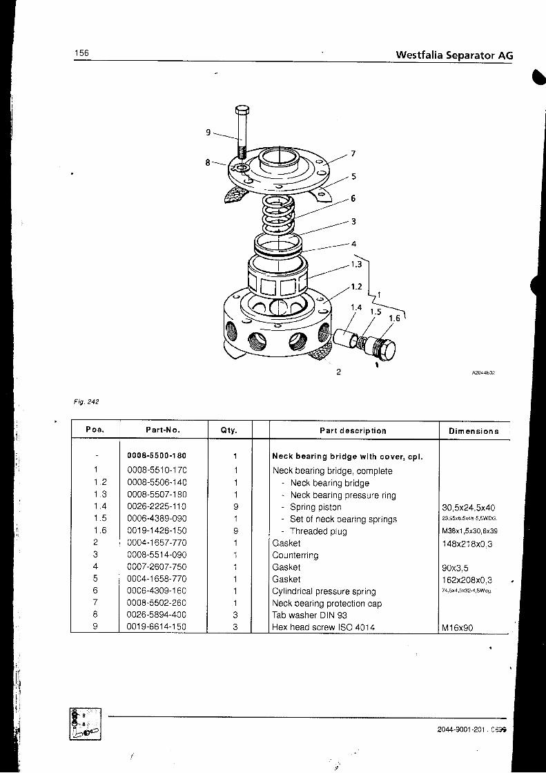
156 ,' Westfalia Separator AG
7
5
6
3
r .3
1 . 2
1 . 4
l
ii:trliji j
I
qG
Fig. 242
P os . P a r t -N o . Q ty . Pa r t desc r i p t i on D i m e n s i o n s
1
L Z
| , . J
1 At . +
t . c
Z
4
6'7
8J
0008-5500-1 80
0008-5510- '1700008-5506-1 400008-5507-1 800026-2225-1100006-4389-090001 9-1 426-1500004-1 657-77A0008-551 4-0900007-2607-7500004-1 658-7700006-4309-1 600008-5502-2600026-5894-40000 '19-6614-150
1
111
,1
11111't
Neck bea r i ng b r i dge w i th cove r , cp l .
Neck bearing bridge, complete- Neck bearing bridge- Neck bearing pressure rrng- Spring piston- Set of neck bearing springs- Threaded plug
GasketCounterringGasketGasketCylindrical pressure springNeck bearing protection capTab washer DIN 93Hex head screw ISO 4014
30,5x24,5x4023,95x6,5x4E-5,5WDG.
M38xl ,5x30,6x39
148x218x0 3
90x3 5162x208x0.374,5x4,5x32-4,5Wd9.
M16x90
2044-9001-201 , Ct39

t c 6 Westfalia Separator AG
I

Westfalia
tP os . Pa r t -N o . Q ty . Pa r t desc r i p t i on D i m e n s i o n s
1 31 5t o
1 7t 6
I Y
ZU
2122232425zo
2728Z Y
en
3 132
34E A
a 7
ee
4041424344
see page 16321 79-3400-01 02179-3447-000001 9-6522-1 502179-3378-000oooT-2572-7500019-6938-3000026-1 337-300001 1-3208-47021 70-3305-000U U I \ ' - J I J / . U b U
2170-3375-0400007-2608-750001 9-6935-300U U Z O . I O O / - J U U
0004-3003-8300008-5508.0600011-6211.i:f.J 021 79-3s75-0300004-2569-770001 9-6935-3000026-1 337-3000004-3004-830see page 16000?6-1 243-3000026-5682-1 70001 9-6202-1 50see page 161001 9-6935-3000004-5358-7000026-601 1 -1 70
l 1Il 1Il 1I
l 3It 1l . 'I
6o
111113e
11111
11
, ' 1. l
&aI
11?
11
lWorm wheel, complete
lWorm whee lshaf t
lClamp plate with toothingHex head screw ISO 4014Bearing cover, completeGasketHex head screw ISO 4017Lock washer DIN 127Angular contact bal l bearing DIN 628RingCol lar nutBearing coverGasketHex head screw ISO 4017Lock washer DIN 127Shaft seal ing r ing DIN 3760Ball bearing protection ringGrooved bal l bearing DIN 625Bearing cover t
GasketHex head screw ISO 4017Lock washer DIN 127Seal ing r ingCentr i fugal c lutch, completeCentering diskFan-type lock washerAl len screw DIN 9'12Revolution indicator, completeHex head screw ISO 4017GasketRetaining r ing DIN 471
M10x90
250x4M10x358 1 0
M40x1,5
85x3 5M10x258 1 0AS35x52x7
o z I r - J r b
'100x150x0,3
M10x258 1 0AS40x60x1 0
1 8x60' l A 6
M16x45
M10x251 65x202x160x2
2044-9001-201 /0699

t o u Westfalia Separator AG
4
2 . 1
z . z
Fig. 244
m When ordering this part, please state diameter of motor shaft end and width of key
2
3
A2044E05
P o s . P ar t -N o, Q ty . P a r t d e s c r i p t i o n D im en s ion s
11 . 11 . 2| .\)22 . 12 . 2
4
2044-3385 -000
2044-3370-00021 79-3365-01 02044-3366-000001 9-6972-1 5021 79-3469-L001 9-6907-1 502179-3367-0000019-0167-300see 0a0e 1 63
1
111
1I
11
tr
Cen t r i f u ga l c l u t ch , com p le te
Clutch drum, complete- Clutch pul ley- R ing- Hex head screw ISO 4017
Clutch driver- Hex head screw- R ing
Hex head screw DIN 561Clutch shoe, compl
M12x40
M8x30
M 1 0 x ' 1 6
2044-9001 -201 / 0699

s)42043E08
Fig. 245
Pos . P a r t -N o . Q ty . P a r t d esc r i p t i on D i m e n s i o n s
'1
z
45
7
311 7-3495-000
31 1 7-3493-0003117-3497-0103117-3488-0100026-1 049-0303117-3487-0100007-2502-830001 9-1 741-80A
1
111z
111
R e v o l u t i o n i n d i c a t o r , c o m p l e t e
Revolut ion indicator housingRevolut ion indicator diskShaftCyl indr ical pin ISO 2338Worm wheelGasketTommy screw
B-3x24
12x3M26x1 ,5x14
H2044-9001 -201 / 0699
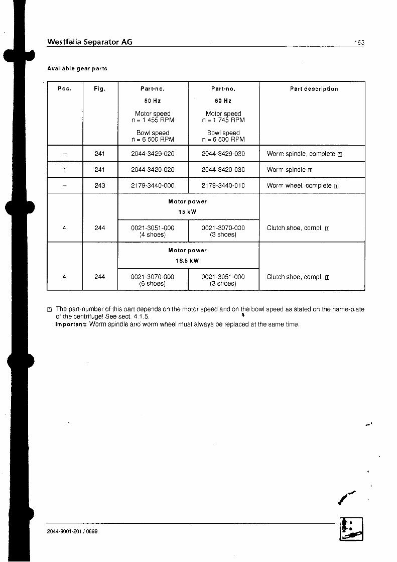
Westfalia Separator AG
Ava i l ab le gea r pa r t s
P os . F i g . Pa r t -n o .
5 0 H z
Motor speedn = 1 4 5 5 R P M
Bowl speedn = 6 5 0 0 R P M
Par t -n o .
6 0 H z
Motor speedn = 1 7 4 5 R P M
Bowl speedn = 6 5 0 0 R P M
Par t desc r i o t i on
241 2044-3429-020 2044-3429-030 Worm spindle, complete n
1 241 2044-3420-020 2044-3420-030 Worm spindle n
243 2179-3440-000 2179-3440-010 Worm wheel, complete n
4 244
M o to r power
1 5 k W
Clutch shoe, compl. t r0021 -3051 -000(4 shoes)
0021 -3070-000(3 shoes)
4 244
M o t o r p o w e r
1 8 . 5 k W
Clutch shoe, compl. n0021 -3070-000(6 shoes)
0021 -3051-000(3 shoes)
tr The part-number of this part depends on the motor speed and on the bowl speed as stated on the name-plateof the centr i fugel See sect. 4 1.5. Ilmportant: Worm spindle and worm wheel must always be replaced at the same t ime.
2044-9001 -201 / 0699
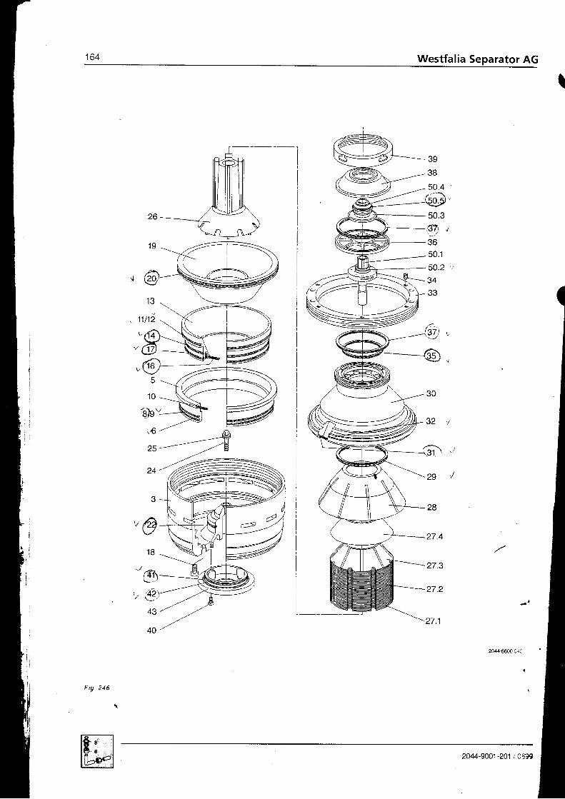
t
4
3938
50
s0.3s 7 ,3650.1
50.2
3433
13
11t1i
"@-
z1
L'
28
27.4
27.3
-27 .2
1 0
t)eY16 -/ "A
25,---;tE
30
.tz
..31 \
,e./ffi
t , i i
43
+v
F i g . 2 4 6
2044-9001-201 ,'0a93
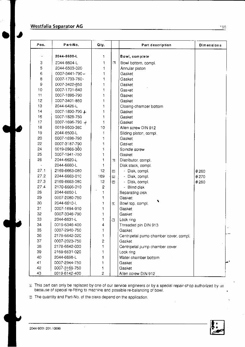
Westfalia Separator AG 5 3
Pos . P a r t -N o . Q ty . P a r t d e s c r i p t i o n D i m e n s i o n s
68
1 01 1
1 2
1 4t o1 ' 7
1 81 0
20zz
2425zo
2 7 . 1z L z
2 7 . 32 7 , 42829.tu
32aa
34? R
a7
ac
A A
4142A A
2044-6600-L
2044-6604-L2044-6503-0200007-3441-790 -
0007-1 733-760-0007-3402€500007-1 701-8400007-1 696-7900007-3401 -850
2044-6426-L0007-1 890-790 +0007-1 828-7500007-16e6-790 +001 9-9503-3602044-6500-L0007-1 698-7900007-3187-790001 e-0966-3600007-1 941 -750
2044-6620-L2044-6660-Lz rov-ooo.J-uou2044-6663-01 021 69-6663-080z | /u -oooo-u tu2044-6650-L0007-2080-7502044-6610-L0007-1 694-91 00007-3346-7902044-663'1-L001 9-6346-4000007-2940-7502178-6642-0200007-2023-7502178-6642-030z roY-oo\ t t -uzu
2044-6698-L0007-2944-7500007-3169-750001 9-61 42-400
1
111111111111
1 011'1
1111
1 21 6 91 2
z
11I
111411211I
11I
n
tr
01
atr
n
tr
I B owl , com p le teII Bowl bottom, compl.Annular pistonGasketGasketGasketGasketGasketGasketClosing-chamber bottomGasketGasketGasketA l len screw DIN 912Sl iding piston, compl,GasketGasketSpindle screwGasketDistr ibutor. compl.Disk stack, compl.
- Disk, compl.- Disk compl.- Disk, compl.- Bl ind disk
Separat ing diskGasket
. lsOWr lop, Compr.GasketGasketLock ringThreaded p in DIN 913GasketCentripetal pump chamber cover, compl.GasketCentripetal pump chamber coverLock ringWater chamber bottomGasketGasketAl len screw DIN 912
0 260g 2700260
This part can only be replaced by one of our service engineers or by a special repair-shop authorized by usbecause of special re-fitting to machine and possible re-balancing of bowl. .The quantity and Part-No, of the disks depend on the application.
2044-9001 -201 / 0699
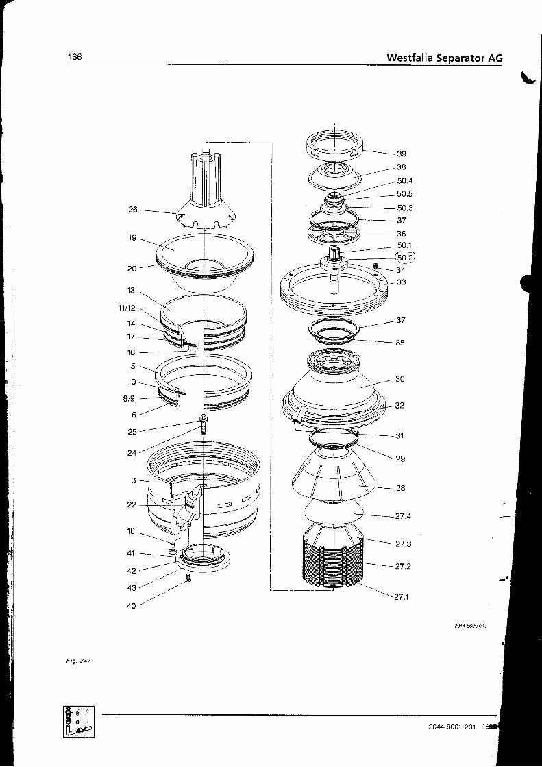
t o o Westfalia Separator AG
39
38
- 50.4
50,5
50.337
3650.1
r"-Y:
34
26
1 9
30
32
31
29
28
27.4
27.3
27.2
27.1
24
.,
22
1 8
41
42
43
40
- 3 7
F ig .247
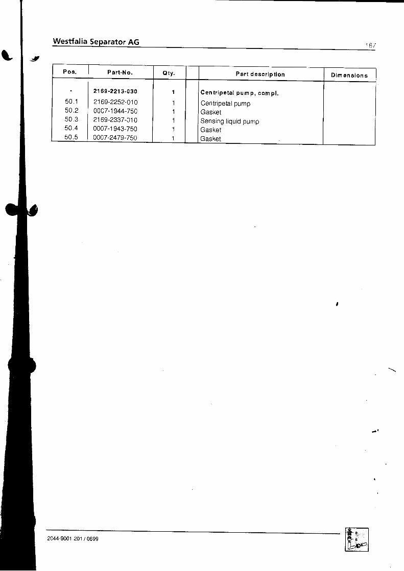
Pos . Pa r t -No . Q ty . Pa r t desc r i p t i on D i m e n s i o n s
t r n l
50,2R n 2
5 0 . 45 0 . 5
2169-2213-030
2169-2252-0100007-1 944-7502169-2337-0100007-1 943-7500007-2479-750
1
11111
C e n t r i p e t a l p u m p , c o m p l .
Centripetal pumpGasketSensing l iquid pumpGasketGasket
2044-9001 -201 / 0699

r 0 6 Westfalia Separator AG
T
30.1
37
36
35
9r4l---
1 .3
1 . 2
3
1 . 5
1 . 7
r_6
A2044EC
F ig .248
2044-9001 -201 , CsD
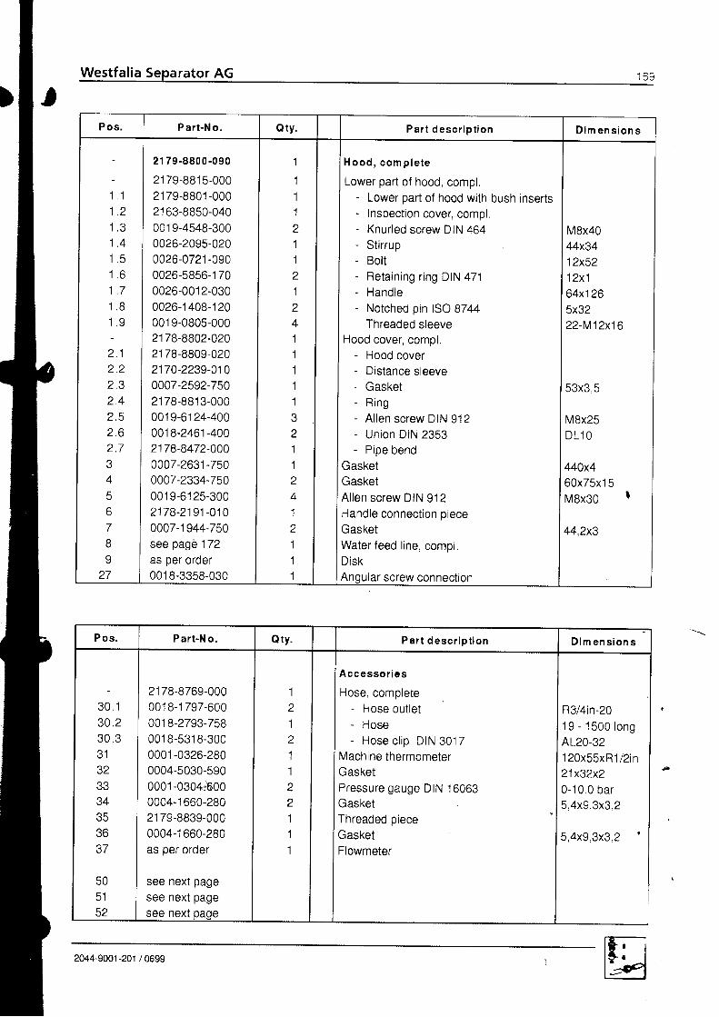
Pos . Pa r t -No . Q ty . Pa r t desc r i p t i on D i m e n s i o n s
. t t
t . a
t . J
1 A
t . c
t . o1 - 7
l o
2 . 12 . 2z . J
2 . 42 . 5z . oz . l
/l
A
67
8
27
21 79 .8800-090
2179-881 5-00021 79-8801 -000
21 63-8850-0400019-4548-3000026-2095-0200026-0721 -090
0026-5856-1 700026-001 2-0300026-1 408-120001 9-0805-0002178-8802-02021 78-8809-0202170-2239-0100007-2592-7502178-88'13-0000019-61 24-4000018-2461-4002178-8472-0000007-2631-7500007-2334-750001 9-6'125-3002178-2191-0100007-1944-750see pag6 '172
as per oroer001 8-3358-030
1
1
11
a
11z
1z
41111'1
211Z
41a
111
l H o o d , c o m p l e t eI
I Lower part of hood, compt.
I Lower part of hood with bush inserts
| - Inspection cover, compl.
I Knurled screw DIN 464
| - Stirrup
| - Rn l tt - - "| - Retaining ring DIN 471| - H a n d l o
- Notched pin ISO 8744- Threaded sleeve
Hood cover, compl,- Hood cover- Distance sleeve- Gasket- R ing- Al len screw DIN 912- Union DIN 2353- Pipe bend
GasketGasketAl len screw DIN 912Handle connect ion pieceGasketWaterfeed l ine, compl.DiskAngular screw connection
M8x4044x3412x5212x164x1265x3222-M12x16
53x3 5
M8x25DL1 O
440x460x75x'15M8x30
44,2x3
P o s . Pa r t -No . Qty. Pa r t desc r i p t i on D i m e n s i o n s
3 0 . 130 .2a n e
JZ
34atr
37
505152
21 78-8769-00000'18-1 797-600001 8-2793-7580018-5318-3000001 -0326-280
0004-5030-5900001-0304:6000004-1 660-28021 79-8839-0000004-1 660-280as per order
see next pagesee next pagesee next oaoe
1z
1211I
a
111
A cc essor i es
Hose, complete- Hose out let- HOSE- Hose c l ip DIN 3017
Machine thermometerGasketPressure gauge DIN 16063GasketThreaded pieceGasketFlowmeter
R3/4in-201 9 - 1 5 0 0 l o n gAL20-32120x55xR1/2 in21x32x20-10,0 bar5,4x9.3x3,2
5,4x9.3x3.2
2044-9001 -201 / 0699

170 Westfalia Separator AG
1 8
1 7
1 9
22
2 1
r 6
l 5
1 4
F ig . zag

Pos . Pa r t -N o . Qty. P a r t d e s c r i p t i o n D i m e n s i o n s
5 01 01 1t z
2425zo
5 1
1 41 q
1 at t
1 81 0
zv
5 22 1zz
001 B-3273-0300005-1 347-000001 8-2461 -030
001 8-2483-030001 8-5388-000as per order21 79-8846-000
0005-1267-280001 9-2376-0302179-1079-0100019-2098-4000005-0231 -600
0005-0202-9000005-0203-9000005-0299-600
0005-1 038-0000019-2233-400
6
14I
1z
1
1z
1z
11z
1z
I Screwed socket
I Conductivity transmitter. compl.Un ion DIN 2353Angle piece DIN 2353High-pressure hose. compl.Solenoid valve, complUnion with orifice plate
TerminalboxCyl indr ical screw ISO 1207Holding plateCountersunk screw 2009Reducing piece DIN 46520GlandGlandCable gland
Pressure switch, complCyl indr ical screw ISO 1207
D L 1 OL]L6
6x550
01 081 306M4x16
M6x '16H P G . 1 1 - P G gPG9x4-8P G 1 1 x 5 - 1 0r u t o
9002377M 5 x 1 2
2044-9001-201 /0699
\ .
I

t t z Westfalia Separator AG
1 2
1 1
1 0
8
1
2
3
4
5
6
Fig.250
P os . Pa r t -N o . Q ty . P a r t d e s c r i p t i o n D i m e n s i o n s
I
z
4
o
b
1 01 l
1 2
21 78-881 6-030
2168-8841-0000004-1 91 5-7800001 -0040-820
001 9-1 621 -030
001 3-1 006-2602178-8448-0100018-4273-600001 8-201 6-000001 B-0023-260001 8-0872-260
1
1z
z
2'1
1'1
111
Water feed l ine , compl .
Sight glass housingGasketSight glass diskThreaded r ingCoupl ing nut DIN 2950PipeNon-return valve, compl.BreatherAngle piece DIN 2950Reducino nipple DIN 2950
38x45,5x1,545,5x2,5-3M48x1,5-38x71l2in-P1
DNl in -TD1200314in9 2 - 1 i n241-1in x 3l4in
? 2044-9001-201 /0699

Westfalia Separator AG I t J
l
2044-9001-201 /0699

II Westfalia Separator AG
3l
1
T1 0
6la42
2044-9001 -201 Csl
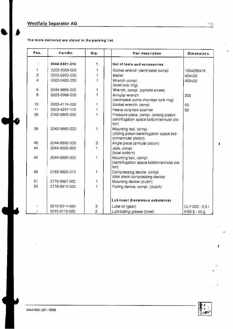
Westfalia Separator AG t a
T h e t o o l s d e l i v e r e d a r e s t a t e d i n t h e p a c k i n g l i s t .
P o s . P a r t -N o . Q ty . P a r t d e s c r i p t i o n D i m e n s i o n s
1
4
68
1 01 1
39
4244
40
49
5 1A E
2044-9901 -01 0
0003-0058-0000003-0200-0000003-0422-030
2044-9855-0000003-3998-000
0003-4174-0300003-4297-1 1 02042-9805-000
2042-9860-000
2044-9893-0002044-9930-000
2044-9860-000
21 69-9820-01 0
2179-9861-0002179-9910-000
001 5-001 4-0800015-0113-020
I
111
11
111
1
1
1
11
z
Set o f too ls and accessor ies
Socket wrench (centripetal pump)Mal letWrench compl(bowl lock ring)Wrench, compl (spindle screw)Annular wrench(centripetal pump chamber lock ring)socket wrench, compl.Heavy-duty box spannerPressure piece, compl. (s l id in$ piston/centrifugation space bottom/annular pis-ton)Mounting tool , compl.(sliding piston/centrifugation space bot-tom/annular piston)Angle piece (annular piston)Jack, comol.(bowlbottom)Mounting tool , compl,(centrifugation space bottom/annular pis-ton)Compressing device, compl.(disk stack compressing device)Mounting device (clutch)Pul l ing device, compl. (c lutch)
L u b r i c a n t ( h a z a r d o u s s u b s t a n c e )
Lube oi l (gear)Lubricating grease (bowl)
1 05x295x1 842x420450x22
205
5060
cLP 220 - 2,5 |K S B s - 5 0 s
2044-9001-201 /0699

t t o Westfalia Separator AG
W(
Fig. 252
Single gear pum p (with part numbers for
22044EOz
pump connect ions compl.)
lf the pump no longer delivers lhe desired oulpul, we recommend inslalling a new pump s.n:.Only the ilemised parts can be supplied as sparesrepairs are loo cosllv.
l
P u m p t y p e P a r t .N o, O u t p u ta t m i n r
r css l r zqs
S e t o f g a s .k e t s
Pos , 1
i e t o f bea r i ngb u s h e s
P 0 6 . 2
Va l ve sp r l ng
P o s . 3
Sea l i ng r l ng
P o s , 4
P u m p c o n -n ec t l ons
(s. . nrxt p.g. l
P i p e s
R25/1 6 FL,DBI.A 1058 91 00-1 5( 1 300 1 60C t068.91 25-000]068 91 20 000 r068,9858 000 )004 178 1159,100R25/20 FL-DBI.A ]068 91 00 1 60 r 650 2 000 1068.9125 000 |068 9120 0001068-9858.00C)004 975-7501 1 7 8 1 1 5 9 1 0 0 1R35/25 FL,DBI.A 1068 9100 170 2 000 2 500 r068.9125,01C|068 9120 010 ]068.9858-01C)004 948 750 1 7 8 1 1 5 9 . 1 1 01 1 1 2R35/31 .5 FL.DBI A 1068-900.180 2 600 3 1 5 0 1068 91 25-01 0 r068.9120,01 0 1068 9858.010)004.948.750t 1 7 8 , 1 1 5 9 - 1 1 01 1 1 2 'R35/40 FL DBI-A 1068-900 19c 3 300 4 000 I068-9125-010t068 91 20 01 0 |068.9858 010 )004 948 750 2178 ' t l 59 11 0 1 1 t2 'R35/50 FL DBI A r068-9100.20c4 000 5 000 |068.91 25 010 ]068 91 20.01Cr068 9858.01 0 )004.1 948.75021 78,1 1 59.1 20R35/63 FL DBI A t068 91 00 21 C 5 200 6 300 1068 9125 01 0 ]068 9120 010 1068 9858 010 )004 948 750 1 7 8 1 1 5 9 1 2 0R45/80 FL,DBI-A 1068 9100-22C b bUU I 000 ]068-91 25.020]068 9120 020 ]068,9858 020 )004 949 750 1 78-1 1 59- 1 30R45/1OO FL,DBI,A 1068-900 230 I 000 10 000 1068 91 25 02C 1068 91 20-0201068 9858.020)004 949,750ll 78,1 1 59-1 30R45fi25 FL,DBI,A 1068-900 240 10 00c12 500 r068.9125-02C1068 91 20 020 1068,9858-020)004 949 750 2178-1159 140 z | 1 .R45/1 60 FL-DBI.At068.900-2501 3 0 0 01 6 0 0 0!068 91 25 02C r068 91 20.020 1068 9858.020)004 949-7502178 1159,1402 1 i 2R65/2OO FL,DBI.A t068 91 00 260 1 6 5 0 020 000 !068 91 25 030 1068-9120-030|068 9858 030 )004.932.75C 169,1 1 59,030 3"R65/250 FL DBI A 1068.91 00 270 20 500 25 00c 1068-91 25 030 t068 91 20 030 1068 9858 030 )004 932.750 169.1159-030
2044-9001 -201 ,/ 0a93
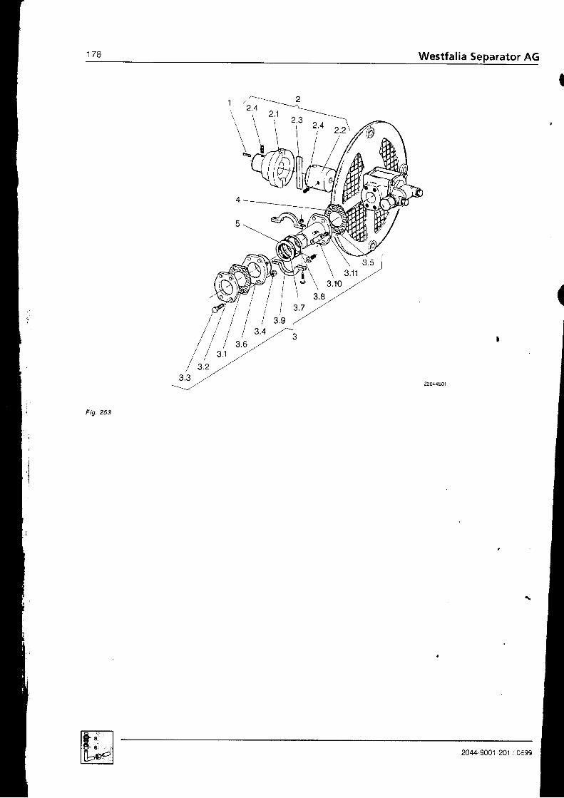
178 Westfalia Separator AG
F ig .253

179Westfalia Separator AG
P o s .
P a r t -N o ,
Qty. Pa r t desc r l p t i on D im en s l on sP u m p t y p eR 2 s / 1 6 F L . O B t . AR25 /20 FL .DB I .A
P u m p t y p eR35 /25 FL .DB I .AR35 /31 .5 FL .DB t .AR35 /40 FL .DB I .A
P u m p t y p eR35 /50 FL .DB I .AR35 /63 FL .DB I -A
1
D 1
2 . 2z . J
3 . 1Q I
Q I
5 . 2
J . Z
J . J
3 . 43 . 4
J . O
J . t
a e
a o
3 . 1 0, l 1 l
4I
21 78 .1 1 S9.1 00
0026-1 744-1 602178-3320-O102178-3323-0102178-3323-O200021 -4795-890
001 9-9063,1 5021 68-2805-1 000004-5426-780
0001 -0828-000
001 9-651 2-1 50
001 3-0279-300
2168-2832-02021 68-2831 -1 0021 68-2831 -1 1 00018-4842-750001 8-4842-0 1 00018-4842-02021 78-1 1 08-000001 3-0291 -300
0004-5426-780
00 t 9-61 45- 1 50
21 78 .1 1 5 9 .11 0
0026-1744-1602178-3320-02021 78-3323-01 021 78-3323-0300021 -4795-890
001 9-9063- 1 502178-2805-200
0004-5475-780
000 1 -0825-000
001 9-6973-1 50
001 3-0280-3002178-2832-0602178-2831-1002178-2831 -110
001 8-4844-7500018-4844-0100018-4844-02021 78-1 1 08-000001 3-029 1 -300
0004-5475-780
001 9-61 66-1 50
2 1 7 8 . 1 1 5 9 . 1 2 0
0026-1744-1602178-3320-02021 78-3323-01 021 78-3323-0300021 4795-890001 9-9063-1 502178-2805-210
0004-5474-780
0001 -0830-000
001 9-6973-1 50
001 3-0280-3002178-2832-05021 78-2831 -090
21 78-2831 -080
001 8-4845-750001 8-4845-0 1 0001 B-4845-02021 78-11 08-000001 3-0291 -300
0004-5474-780
001 9-6 1 66-1 50
1
1
1
1
1
1
I
2z
2
86
2
z
42I
d
I
P u m p c o n n e c t i o n ,c o m p l .
Feather keyPump coupling compl.- Coupling half (separator)- Coupling half (pump)- Flexible coupling- Threadcd pin DIN 916
Junclion assembly, compl.- Gasket- Gasket- Gaskel- Flange- Flange- HexheadscrewlSO4014- HexheadscrewlSO40lT- Hexagon nul ISO 4032- Hexagon nul ISO 4032- Expansion joinl, compl.- Expansion joini- Expansion joinl- Gaskel- Gaskel holder- Clamp, compl.- Plate- Hexagon nut DIN 985
GaskelGaskelGasketAllen screw DIN 91 2Allen screw DIN 912
A 6x6x35
84x9,8AM 8x10
59x70x1,594x8297x102x1,5i l n
2 i nM 10x40M '12x45
M r 0M 1 2
I
M 859x70x 1,594x8297x102x1,5' M ' 1 0 x 3 0
M 12x35
2044-9001-201 /0699

1 8 0 Westfalia Separator AG
3
l
il,l/ l t ' t '
i 3.2 ,,.'3.3 ,,r'
Fig. 254
2044-9001-201 /0693

rator AG
Pos .
P s r t .N o .
Qtv. Par t desc r i p t l on D i m 6 n s i o n sP u m p t y p eR45/80 FL-DBI.AR45/1 OO FL-DBI-A
P u m p t y p eR45/125 FL.DBI-AR45/160 FL-DBI.A
P u m p t y p eR65/2OO FL-DBI.AR65/250 FL-DBI-A
1
2 . 12 . 2t e
z . J
Q I
3 . 1J . Z
J . Z
3 . 4
J . T
e q
3 . 1 0Q 1 1
445
21 78-1 1 59-1 30
0026-1744-16021 78-3320-03021 78-3323-01 02178-3323-0400021 -4795-890
001 9-9063-1 502178-2805-2100004-5474-780
0001 -0830-000
001 9-6973-1 50
001 3-0280-3002178-2832-0502 1 78-2831 -090
2178-2831-080001 8-4845-7s0001 8-4845-01 0001 8-4845-02021 78-1 1 08-000001 3-0291 -300
0004-5474-780
00 1 9-61 66-1 50
| 2 1 7 8 - 1 1 s e . 1 4 0
I| 0026-1744-160
I zr ze-sszo-oso| 2178-3323-010
| 21 78-3323-040
| 0021 -47s5-890Il -001 9-9063-1 5021 69-2805-1 1 0
0004-5427-780
0001 -0829-000
001 9-6974-300001 3-0280-3002169-2832-02021 69-2831 -040
21 69-2831 -050
001 8-4t146-750001 8-4846-01 0001 8-4846-02021 78-11 08-000001 3-0291 -300
0004-5427-780001 9-61 66-1 50
21 69-1 1 59-030
0026-1744-16021 69-3320-00021 69-3323-00021 69-3323-01 0
0021 -4797-890
001 9-9063-1 50
0004-301 5-780001 9-6200- 1 500001 -1 263-000
1
111111
z
2z
28
8
2z
4
2
.J
I P u m p c o n n e c t i o n , c o m p l .I
I Feather key
I Pump coupling compl.
| - Coupling half (separator)
I Counling half (pump)
| - Flcxible coupling
I Flexible coupling
| - Threaded pin DIN 91 6
Juncl ion assembly, compl.- Gaskel- Gasket- Flange- Flange- Hex head screw ISO 4017- HcxheadscrewISO4017- Hexagon nut ISO 4032- Expansion joinl, compl.- Expansion joint- Expansion joint- Gaskel- Gasket holder- Clamp, compl.- Plale- Hexagon nut DIN 985
GaskelGaskelAl len screw DIN 912GasketAllen screw DIN 912Flanqe
A 6x6x35
84x9,884xl 1,8AM 8x10
97x102x1,51 09x1 1 4x1 ,52in2 1 l2 inM 12x45M f2xsoM 1 2
M 897x102x1 ,51 0 9 x 1 1 4 x 1 , 5M 1 2 x 3 51 31 x ' l 3 5x 1 ,5M 15x353 r n
2044-9001-201 /0699

t182 Westfalia Separator AG
r tg. zc'
I
II
P os .
Pa r t -N o .
Qty. Pa r t desc r i p t i on Dim en s l o n sP u m p o u t p u t
up to 2 000 l / h
N W 2 5
P u m p o u t p u t
3 0 0 0 - 4 s 0 0 t / h
N W 4 0
1
2
5
n
7
7
I
8 8 2 1 - 2 1 1 0 - 1 0 0
8821-2115-010
001 9-6937-300
0007-2646-750
BB21-2114-000
8821-211 9-000
0004-5454-780
0001-0163-000
001 9-6970-1 50
8822-2110-040
8821-2115-010
001 9-6937-300
0007-2646-750
8821-2114-000
8821-2119-000
0004-5454-780
0001 -01 46-000
001 9-6970-1 50
1
1
1
1
1
2
2
2
4
Pre-st ra iner , 6om pl . (on specia lorder)
Housing coverHex head screw ISO 4017
Gasket ,
Strainer housing
Strainer insertGasketWelded flangeWelded flange
Hex head screw ISO 4017
M 10x30
126x4,5
4417Ox112x1 ,5
l i n
1 1 l 2 i n .
M 12x30-8.8
The pre-strainer protects the product pump from coarse impurities
2044-9001 -201 / 0E93
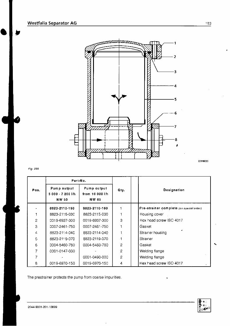
Westfalia Separator AG C J
Fig.256
The prestrainer protects the pump from coarse impurities
P o s .
Pa r t -N o .
Qty. Des igna t i onP u m p o u t p u t5 0 0 0 - 7 2 0 0 l l h
N W 5 0
P u m p o u t p u t
f r o m 1 0 0 0 0 l / h
N W 6 5
1
a
6a
8
8823-21 1 0-1 50
8823-21 1 5-030
001 9-6937-300
0007-2461-750
8823-2114-040
8823-21 1 9-070
0004-5460-780
0001 -01 47-000
001 9-6970-1 50
8823-21 1 0-1 60
8823-21 1 5-030
001 9-6937-300
0007-2461-750
8823-2114-040
8823-2119-070
0004-5460-780
0001 -0490-000
001 9-6970-1 50
1
1
1
1
1
a
z
z
4
Pre-s t ra iner gom p le te @n spec ia l o rder )
Housing cover
Hex head screw ISO 4017
Gasket
Strainer housing
Strainer
Gasket
Welding f lange
Welding f lange
Hex head screw ISO 4017
2044-9001-201 /0699
Westfalia Separator AG r 8 5
6.1 The regulat ing r ing6.1.1 Determin ing thesize of the regulating ring with the aid of
the diagram6.1.2 Determining the size of regulat ing r ing by experiment6,2 Dismantl ing and assembling the bowl
B o w l , c o m D l e t e . . .Single centr ipetal pump, compl. , . . ,H o o d , c o m p l e t e . . ,
187
1871 8 9
t Y z
1 9 31 0 6
2044-9001 -201 / 0699 MAru
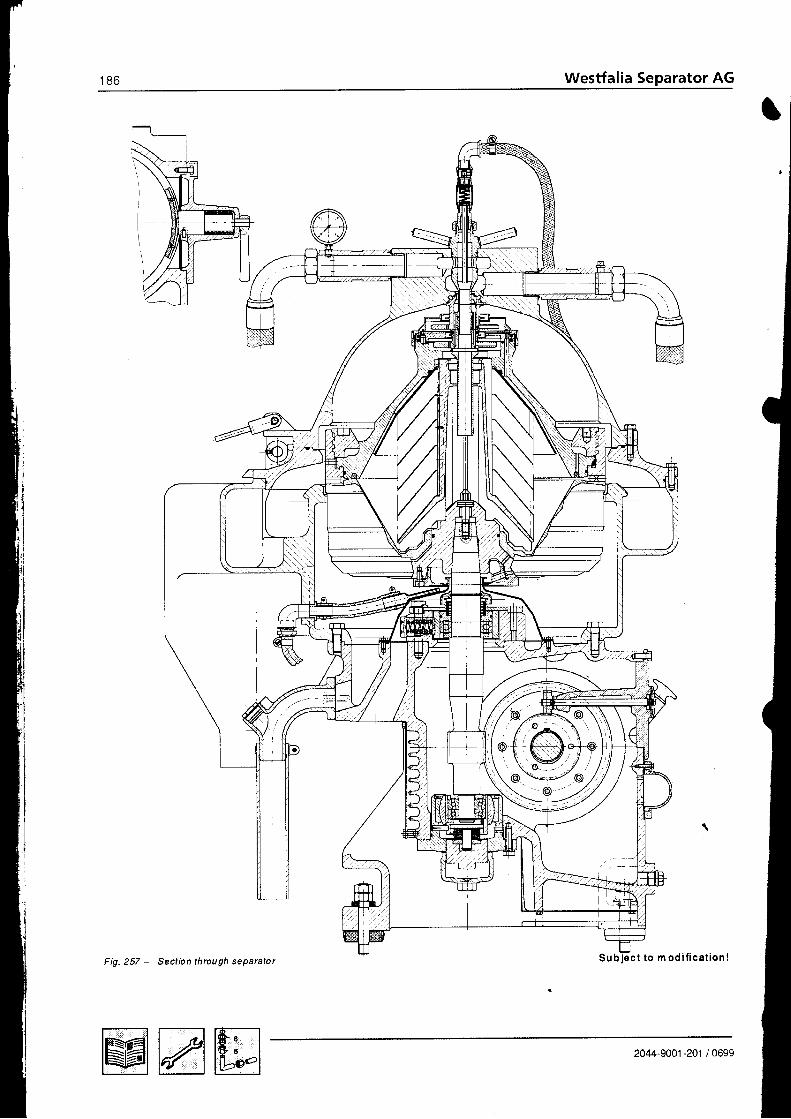
1 8 6 Westfalia Separator AG
t
I
t to m od i f i ca t ion lFig. 257 - Sect b n th rou gh se paralo I
2044-9001-20r /0699Mmru

6 . 1 T h e r e g u l a t i n g r i n g(using oil purif icaiionas an example)
6 . 1 . 1 D e t e r m i n i n g t h e s i z eo f t h e r e g u l a t i n g r i n gw i rh t he a id o f r hed iag ram(using oil purif ication asan exampte)
F u n c t i o n o f t h e r e g u l a t i n g r i n g
Optimum dewatering of oils containing water is only possible if the bowl is correcilyadjusted to the difference in density between the oii and the water.The regulating ring with the correct inner diameter, i,e with the diameter that corre-sponds to the density difference between the oil and water, should therefore be se-lected from the set of regulating rings (with different inner diameters) supptied withthe separator and fitted in the bowl.
The inner diameter of the regulating ring to be selected can be determined with theaid 0f the diagram or by experiment. The rule of thumb is:r smal l regu la t ing r ing fo r heavy o i l ,. la rge regu la t ing r ing fo r t ighr o i t .
The diagram can be used to determine- the inner diameter of the regulat ing r ing ano.- if desired the density of the oil
for a given separating temperature. provided that the densitypf the oil is known ata temperature between 15 oC and g0 oC.
E x a m p l e
\l f no regulat ing r ing with the determined inner diameter is avaitable, a smaler r ingcan be machined to the required size. Before doing that, however, check biexperiment whether the regulating rings furnished withihe separator are adequatefor optimum dewatering. Experience has shown that the regutating rings suppiiedare normally adequate.
G i v e n :
Density of oil at 20 oCPoirQo"c = 0,873 kg/dm3
Separati ng temperature L = /U " t r
To be de te rm ined :
Inner diameter of regulat ing r ing d = ?
Density of oil at 70 oCPoil 7o "C = ?
Dete rm ined :
Inner diameter of the regutat ing r ingaccording to the diagram
d = 1 2 6 m m
Density of oil at 70 oCaccording to the diagram
Poir 70"c = 0.838 kg/dm3
2044-9001-201 /0699 MAffi

1 8 8 Westfalia Separator AG
Sep a ra t i n g t empe ra tu re1 9 0 - 2 1 2 " F
P 1t<gior3y l.oo90 -t000c
l ,O0 p (ks/dm3)
0,980,99
0,96
0,91
0,9?
0.90
0.88
20 30 10+ 0,7690
-60 80 r00 120 r10 t6o t io t io-zrz"FSepa ra t l n g t em pe ra tu r e
Exam ple: To be determ ined: Regulat ing r ing d iameter and po;1 7e.6,
G i v e n :
D e t e r m i n e d :
Poir20 "c = 0.873 kg/dm3Separating temperature 70 oC
Regulat ing r ing diameter = 126 mmPoirTo "c = 0.838 kg/dm3
Fig.258 - Diagram for determining correct size of regulating ring
t00
10
r20
50
t{0
60
160
70
Mmru 2044-9001-201 / 0699

6 , 1 . 2 D e t e r m i n i n g t h e s i z eo f r e g u l a t i n g r i n g b yexpe f lm en t(using oil purif ication asan examole)
To avoid emulsification, begin the test by inserting a large diameter regulating ringand then switch to the next smaller.
l f the regu la t ing r ing is too ta rge ,- the water discharging through the water ouilet will contain oil.
l f the regulat ing r ing is too sm ai l ,- s l ight emulsi f icat ion wi l l occur or- the oi l discharging through the clean oi t ouf let wi l l contain water.
The milky or dirty appearance of the water is quite normal: it is caused by the oilwasnrng process.
A separating zone between the light and heavy liquid forms in the bowl; the centreof this zone is the separat ing l ine.lf the correct regulating ring has been selected, the separating line will be positionedat the outer rim of the discs.
After opening the bowl, the separating line between water and oil, which is normallyfound on the underside of the separating disc, will indicate the position of the sepai-at ing zone.
Cor rec t ly se lec ted regu la t ing r ing. The separating lipe between water
and oi l is at the buter edge of thediscs.
E ffec t:- The discharging clean oil is free from
waIer.- Thedischarging water is f reefrom oi l .
Fig
I nne r d iam e te r o f r egu la t i ng r i ng t oow i d e
o The separatingand oi l- is located far
and- is too close to the outer rim of the
separating disc \
E ffec t:- The discharging clean oil is free from
waIer.- The discharging water contains oi l or- Oil breaks the water seal.
line between water
outside of the discs
2044-SOO1-201 /0699 Mmffi
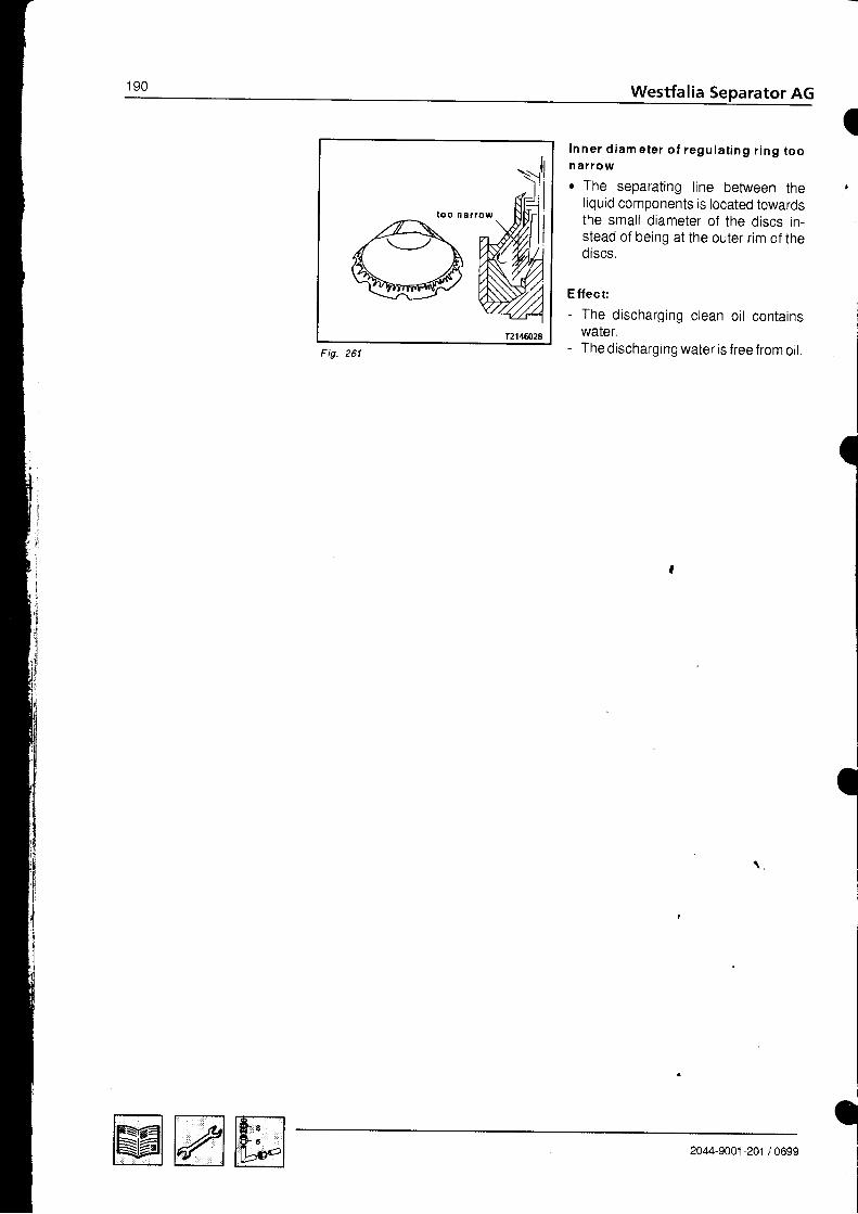
1 9 0 Westfalia Separator AG
I
t oo na r row
Inner d iam e ter o f regu la t ing r ing toon ar rowr The separating line between the
liquid components is located towardsthe smal l diameter of the discs in-stead of being at the outer rim of thediscs.
Effect:- The discharging clean oi l contains
water.- The discharging water is f ree from oi l .Fig
I
I
\ ,
aMmm 2044-9001-201 /0699
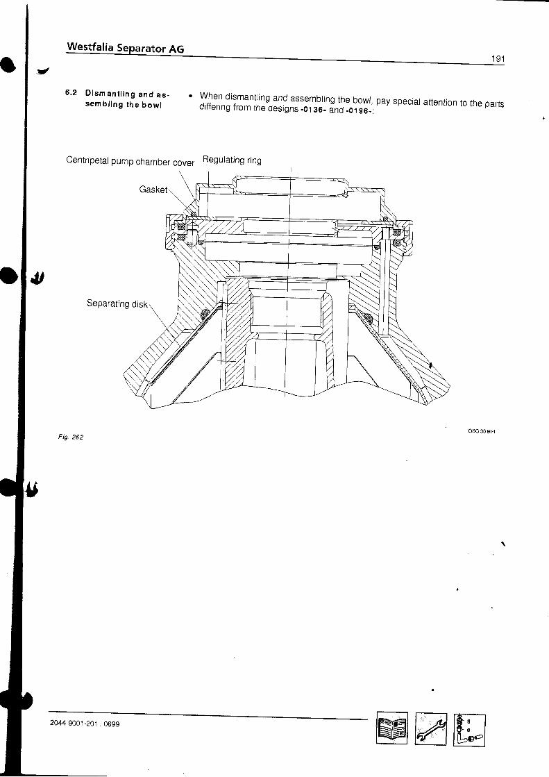
6 . 2 D i s m a n t l i n g a n d a s -s e m b l i n g t h e b o w l
Centripetal pump chamber cover Regulating ring
Separat ing disk
Fig. 262
' when dismanring and assembring the bowr, pay speciar attention to the partsdiffering from the designs _01 36_ inO .oigs-:
2044-9001-201 ,'0699 MAru

l J l Westfalia Separator AG
Descript ion and Part-No. of the parts di f fer ing from the designs -0136- and .0196-
F ig .263
osc-3G91
l
o l e s o p e n
P os . Pa r t -N o . Q ty . D e s i g n a t i o n
230ean
340350
2042-6650-040
2042-6691 -000
2042-6642-000
0007-2942-750
1
1
1
1
B o w l , c o m p l e t e
Separat ing disk
Set of regulat ing r ings
Centripetal pump chamber cover
Gasket
Mmffi 2044-9001 -201 / 0699

Westfalia Separator AG
F ig .264
A A
40
30
1 0
20
$,
Des ig n a t i on
1 02030406n
2042-2213-010
2169-2252-010
0007-1 944-750
2042-2337-020
0007-1 943-7500007-2479-750
s i n g l e c e n t r i p e t a l P u m P , c o m p l .
Centripetal pump, complGasketSensing l iquid pumpGasketGasket
2O44-9OO1 -201 / 0699 Mmru
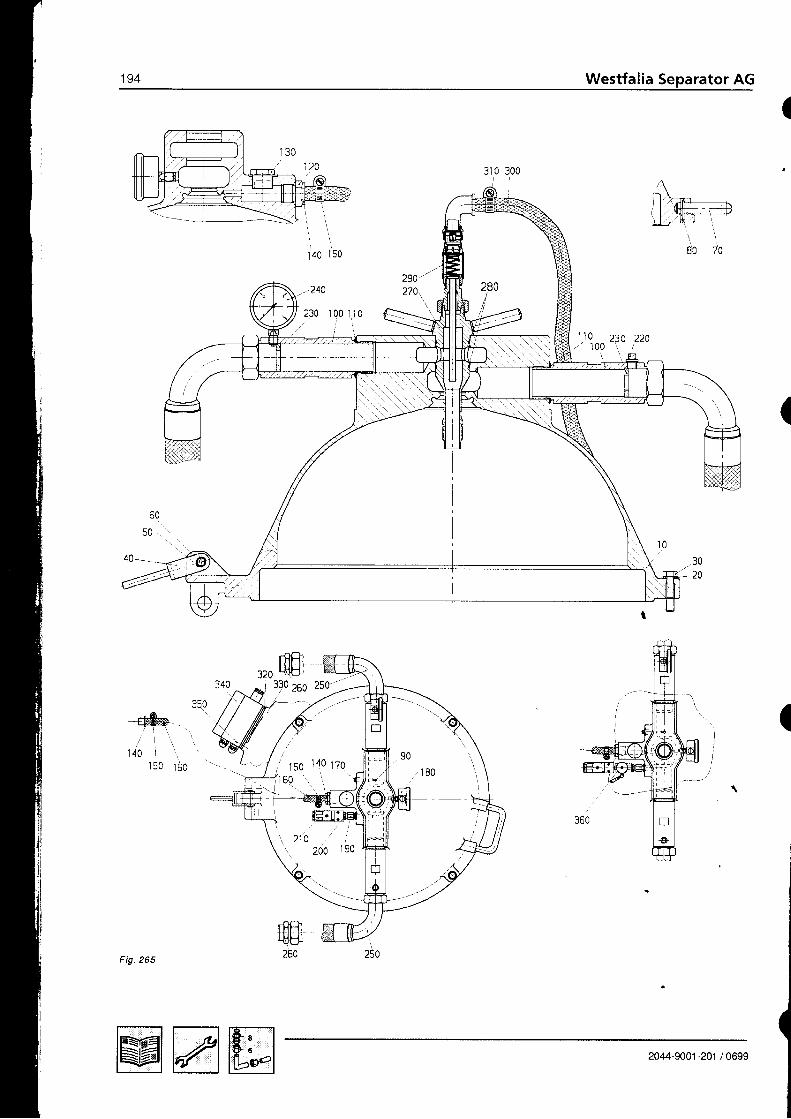
194 Westfalia Separator AG
140 I 50
- 240
.rnffi-ffif'zzo25s zso-t
(
(
MAffi 2044-9001 -201 / 0699

Westfalia Separator AG 1 9 5
3
O lsr
P os . P ar t -N o. Qty. D e s i g n a t i o n
1 0
zv
30
40
50
70
80
90
1 0 0
1 1 0
120
1 3 0
1 4 0
1 5 0
1 6 0
170
1 8 0
1 9 0
200
214
220
230
240
250
zov
270
280
290
300
J I U
320
340aKn
2044-880 0 -0 80
2044-8808-000
0026-0165-400
001 9-0235-300
0026-2095-020
0026-5856-1 70
0026-0721 -090
0026-001 2-030
0026-1 408-1 20
001 9-8972-1 50
2042-7462-010
0007-2879-750
001 B-3352-600
001 9-1 423-030
001 8-1 796-600
0018-3816-300
001 8-2786-758
001 8-0988-260
0001 -0279-600
0018-3273-030
0018-2461-030
0005-431 5-000
001 8-0988-260
as per oroer
as per oroer
001 8-6658-01 0
001 8-661 5-000
2042-2191-000
0007-1944-750
2144-8816-000
001 8-2786-758
0018-3816-300
2048-1 079-000
001 9-2097-400
0005-431 7-280
001 9-6110-300
as per oroer
1
1
4^
1
a
1
1
z
'1
2z
z
1
z
z
1 .500 m
1
1
1
1
1
1
1
1
z
2
1
z
11 .500 m
z
1
1
1
H o o d , c o m p l e t e
Hood
Washer
Hex head screw
StirrupRetaining r ing
Bolt
Hand le
Notched pin
Threaded pin
Threaded connection
Gasket
Reducing connector
Threaded plug
Hose outlet
Hose cl ip
HoSe
Plug
Pressure gauge
Screwed socket
Screw coupl ing
Pressure switch, comp,
PIug
Diaphragm
Flowmeter
Corrugated hose, compl.
Connector
Handle connect ion piece
Gasket
Water feed line, compl
Hose
Hose cl ip
Retaining plate
Countersunk screwTerminalbox
Allen screw
Pressure gauge cock
2044-9001-201 /0699 MAH
Westfalia Separator AG
T a b l e o f l u b r i c a t i n g o i t s . . . . . t . . . 1 9 8Comments on table of lubricating oils . . 199The health hazards invotved when handting heavy oirs and lube oils . . . . zooSpecifications for the use of separators . . ZO1
2044-9001-201 /0699

1e8 Westfalia Separator AG
T a b l e o f l u b r i c a t i n g o i l s
3
.I
; E
? 2
. 3
q - _
FI
gg|lit
rer[L E I 5aa 0 : tov ! l tH ! i l t . r . ( ih ?q 5 , , : ru 07
0 . l F l o ! ! ! l l r t l l . 0 f ? r e . - r u t 6
@ t a l 1 . t r , . r q n t a : r : n : ! " ( f a q e / z u u 6 r -a r E s o r J i i I n q i o a t a ? 5 / , u
r n i n u o u i o | l - n l t . o t a q 5 , , t r u g a
5Di . .wF' |ru!or r : :LlL "0r l i !1 i1 g::
0 : I c . ! - D N D 0 0 t i l a ! t . o r , . q . / _ u u b 30t t : ! I I a r Jo t Eor ra r t . i ) t 6q s / , t rd F !
00 . fL ,n .du .J ro i ! tN l , !n i ] iP ,n" q l
0 v . - .
. : . ' ( . t a a , - ^ A ,
$to ia f l : ! ! ! l ! l0 ! S ! ,1 l .o i i3q
1 l ! : H l \ t d v t r t ! ! , 5 ! : l . ! F ' r ! .;ry1 1 r l l i ! ! a f v l i ! , ! ! t _ . ! b : q : / . t r b 0 i l
) l L E x r N l d S r H l C t t E ! l j , o n a ! e / 7 t r u 0 !
laa iE l l : l lnc:! 1"0! rq . / r{u O:
lkr$l : L a E ! Y t O E l t . c o t a q e . , r ( u E a tr t L I : N l € t r 1 . o t ? q s _ t r u ! l
0 l l l l l v ! ? l f l v r i i l . ! f : o = : [ u s r
.ectt<
E0 € r H ! ! a l : s : l l d l i ! l ! ! r F , € q s / . ( u 0 ! L
. r 0 t Y i n l r ! i 1 { r ! l . ! f a q e / r r d o a
! ! r Y t 5 r t 8 a l ! ! ! , 0 t a o E / . ( u q :
s3 c t l v : r l x n r r l t o o F r e ! 5 / _ ( u
c € l v : l ! o J . c l l o t , e q s / , u u 6 r
-9q rt: 1! i l '1i!
0 t . ! o u r c o . lI lLl"or I"! .,: l i ! lI r ! ! l . j t a q . / ? r u r i
&o=
1 J : i . 6 . . r . 5
0 ! L d : N V 1 ! V ! 9 0 E S 3 l . 0 r a a s / r r u 0 l
! c L H l l n l i . ! E : l a o f , a . 5 / i t r u 0 a
ts' 7 - , - . t D r - . r . 9 " , , r . . . , , (
c i d ! l 0 l . e r r l l : 8 l o 0 r i q s / : t r u i l
€,
o i i z ! \ l l : o r v r . o r r q s , r u o :
l 0 l I f l 0 \ ! t 0 ! i o r i l . 0 t " q 5 . t r u 0 l
F
tlr :t r r i l
-=---l-=:=:I 5 a ) 0 B u - ! r r i t 5 t 0 ( -
: a 5 i. ! ! : = =- e -, r i = r =
5 o : - * = =
! =
- J
; , �; ;
Y . ! 9
r = . : 5 3 =
[ - tL : ]
r l oI d - l \ d - l
a - I o l L i - r IE i I
E-|L-:1
-fl t I 1 l r ' t l r
n ! n _ t f . l t ( ,
< r < - L : r e o
c i c r c ) r J = ( l c r
Fig. 266
O
e
a
=q
: - l
E
I
2044-9001-201 /0699

o v
O - t l
Ort
C o m m e n t s o n t a b l e o f l u b r i c a t i n g o i l sl o r m i ne ra l o i l sepa ra to rs
f rom Wes t fa l i a Sepa ra to r AG
I
Faultless, functioning of .separators very much depends on the proper type of lubricating ort used, since ahigh grade oil selected to meet all service requirements, will minimke trd wear, tnuJextEnoing the servicelife and increasing the operating safetyFor the lubrication of our mineral oil separators we recommend to use the oils specified by us srnce continu-,tJir!:3
',tJJ,iecks are performed bv westfalia separator. oitJproposed from some tirmi ire not subjectedTherefore, Wesffalia Separator cannot give a performance guarantee for those oils.Be sure to select only high grade solvelnt refined producti."-
-' - '-
The specified oil types meet the requirements according to DlN. Under unfavourable operating conditionse g high temperatures, the quality of the oils may be insufficient so that more eti[Gni oi[ " g syntheticoils, must be used. lf necessary, consult Westfalii Separator AG. -
5ij tnt different separator types and oil types the viscosity ranges are specified in the tabte of tubricating
some of the separators mentioned have immersion lubrication. power is transmitted to a worm wheel gearwith a relatively high tooth load. The operating temperature of the separator exceeds normaly g0 oc. Atthose temperatures some oils age quickty, so inat il iey rrave to o" .n"ng"d prematurely.Be su re not to use lubricating oils with viscosities lower than those specified in the table. Due to the possibilityof the oi l f i lm brea.king down, oi lof too low a viscosity wit tgive-nsr ir t i "nt lubr icat ion, result ing in increasedwear. However, oils with a slighily higher viscosity than s[ecified may be used,Bear in mind that the viscosity groups SAE 30, 10 a.nd 50 (SAE = Society of Automotive E ngineers) coverlarger viscosity ranges and b6 sure io select lubricating oilswith viscosities not lower than therninimum va-lues of the viscosity ranges restricted for the oiterentiep"r.to,. tvp",EP oi ls (EP = 5x1t"te Pressure), i .e. oi ls with high pressure addit ives, may only be used i f they have nocorrosive effect even in, the event of water seepinglntb tne olr iump.-sin." tests carried through with varioustypes 0f standard EP oils have shown that therb are great differences in the intended effect of marKed interfa-
:5iX?yitl.il3l.3H9!".t,u"ness or EP additives on 5ronze toothed wheers, e p oirsmi}/ onty be used ir they
2044-9001 -201 / 0699
^a

T h e h e a l t h h a z a r d s i n v o l v e d w h e n h a n d l i n g h e a v y o i l s a n d l u b e o i l s
As a result of the deterioration in quality of fuel oils, the danger has arisen that the heavy oils used on boardcontain greater amounts of substances injurious to health.lhese include: '
.- polycyclic aromatic hydrocarbons,- lead compounds,- chemical residues,
An increased amount of polycyclic aromatic hydrocarbons is also present in used lube oils (waste oils)The health hazards for the engine room staff depend to a large extento on the concentratiOns of the dangerous substances,o the ambient air ( inhalat ion of oi lvapours/oi lmist) ,. the intensity and duration of the contact with the skin or mucous membrane.
Possible sh orr-rerm effects:r headaches,. dizziness,. nausea,r i tching or burning of the skin,
Possible lon g-term effects:r al lergic react ions, especial ly skin al lergies,. festering inflammation of the skin pores (oil-acne).. damage to the central nervous system after inhalation over a long perroo.. skin cdncer caused by direct skin contact over a long period,. Lung cancer or cancer of the digestive organs after inhalation over a long period \
(not certain as the causes are difficult to separate from the effects of smot<ing and alcohot;.
Code o f p rac t ice and persona l p ro tec t ive measures :. Avoid skin contact with heavy oils or lube oils if possiblel
- Wear suitable protective gloves.- Apply a protective ointment to the skin (e.g. ointment no, z6), especially if no protective gtoves are
worn!o Avoid breathing in oil vapours if possibler. l f possible. improve the air c irculat ion in the rooml
Ful ly open the air regulat ion f laps in the out lets of the air supply ducts ' in the centr i fuge and f i t ter area.. Wash affected areas of skin frequenily and thoroughly!
Apply protective ointment to the skinl' Personal hygiene is of the utmost importancel. Change dir ty overal ls regular ly!' Exercise special care when carrying out maintenance work on and cleaning heavy oil and lube oil centri-
fuges and filtersl
f
]
Westfalia
2044-9001-201 /0699
l r
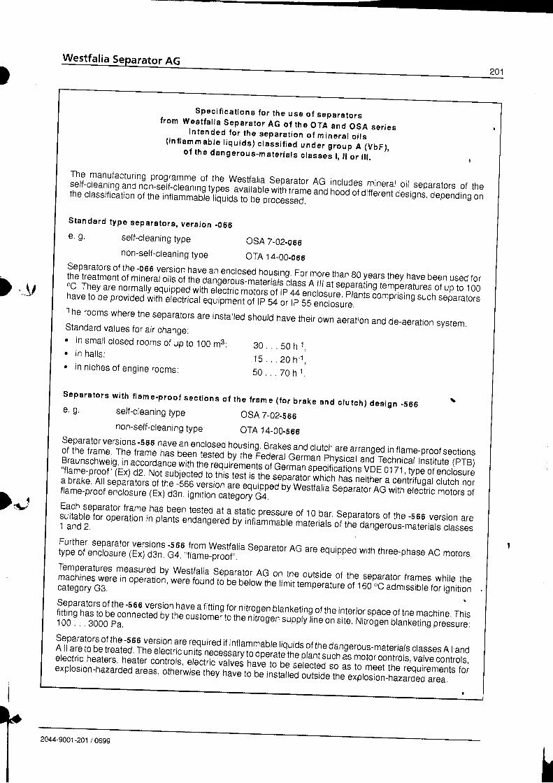
)
.v)
)*'
I
II
Spec i f i ca t i ons f o r t he use o f sepa ra to rst rom Wes t fa l i a Sepa ra to r AG o f t he OTA anc l OSA se r i esi n t e n d e d f o r t h e s e p a r a t i o n o f m i n e r a l o i l s( i n f l a m m a b t e t i q u i d s ) c t a s s i f i e d u n a " i f r o r p A ( V b F ) ,
o l t he dange rous -ma te r i a l s c l asse i l , l l o r l l l .
The manufacturing programme of the westfalia Separator AG incrudes mineral oil separators of the"r'J';1i",TiH,ilf ;,',H?ii3'fin$YJYfii'.Slllgly.lg.'i;;;'iooo oroirrerenioesisn; oepeno;g'oi
Standa rd t ype sepa ra to rs , ve rs ion _066
separators of the '0 66 version have an enclosed housing. For more than g0 years they have been used forthe treatment of mineral oy1: o1$,9i1g-"lJr:' r.r"riars irass A rrr ,i ..q,ating tempbratures or up to .1 00oc They are normally equipped with el6ctric molols of rp 44enctosi,'re prants comprising such separatorsnave to be provided with erectricar equipment of rp 5a., ri ss "r.Lrrr".
e. g, self_cleaning type
non_self_cleaning type
e. g. self-cleaning typenon_self_cleaning type
osA 7-02-056oTA 14-00-066
3 0 . . . 5 0 h - 1 ,' 1 5 , . . 2 0 h - 1 ,
5 0 . , . 7 0 h 1 .
f rame ( fo r b rake and c lu tch) des ign _S66 \
osA 7-02-566
oTA 14-00.s66
I ne rooms where the separators are installed shouldhave their own aeration and de_aeration system.Standard values for air change:r in smal l c losed rooms of up to 100 m3:o in ha l l s :. in niches of engine rooms:
Separa tors w i th f lame-proof sec t ions o , the
separator versions -566 have an enclosed housing Brakes and clutch are arranged in flame-proof sectionsof the frame The frame has been b;t"d by the Feoerai cermai'nny.i.rr ind r".nno., Institute (prB)Braunschweig' in accordan." *itn t'" r"{rir.lgntg ot cermin sf eciftcations vDE 01 71 , typeof enctosure"flame-proof ' (Ex) d2 Not subjectedloln'i."t"rt is tne sepaiitoiiuii.r.r n". neither a centifugar crutch nora brake All separators of the -'soo version aie equrppeo nv w*sti.ria separator AG with erectric motors offla me-proof enctosure (Ex) d3n,-ignitron'cailgory C+.Each separator frame has been tested at a static pressure of 10 bar. separators of the -566 version areiitff!
for operation in plants enoangeieJby infldmmaore materlrs of the dangerous-materiars crasses
;i'JTi,.n:irfft:i;fiiil: #!:'#gil.Jr?". separator AG are equipped with three-phase AC motors,Temperatures measuredjl
[99t1aria separator AG on the outside of the separator frames whire theffi:iffi #:re
in operation, were found to'be oerow irre rimit t#pl,.t*e or r oo'.C io*ir.ior" for ignitionseparators of the -5 65 version have a fitting for nitroggl!]anr<etjng of the interior space of the macnine. rnlslilit
'5J33e connected ov tne custom"ito"tn. nitrogen suppryine on site. Nitrogen blanketing pressure:
separators of the -s 66 y9lion are required if inftammabte tiquids of the dangerous-materiats crasses A I andA ll are to be treated' The electric utid;";;ra.y fojry3l;th" pr.nirr"n as motor contrors, varve contrors,electric heaters' heater controls, etectra vilves have to be serected so as to meet the requirements forexptosion-hazarded areas, otherwise they have to oe rnstatteo-outi]oe tne exprosion-hazarded area.
I2044-9001 -201 / 0699