473 engine
TRANSCRIPT
Page 1, Total pages 119
If you find any incorrect information, or you request more details or demonstrations, please send email to [email protected] to obtain support.
Engine
Catalog
Chapter 1 Gasoline Engine...................................................................3
Section 1 Overview .......................................................................................... 3 1.1 Major Technical Parameters .......................................................................................3 1.2 Technical Parameters for Maintenance ......................................................................4 1.3 BYD473QA/QB Gasoline Engine Tightening Torque Table.........................................7 1.4 BYD473Q Engine Special-purpose Part List ..............................................................9
Section 2 Cylinder Head .................................................................................. 9 2.1 Adjust Valve Clearance ..............................................................................................9 2.2 Remove/Install Crankshaft Pulley.............................................................................10 2.3 Remove/Install Silent Timing Chain.......................................................................... 11 2.4 Install Crankshaft Front Oil Seal...............................................................................19 2.5 Remove Cylinder Head Cover..................................................................................19 2.6 Remove Cylinder Head ............................................................................................20 2.7 Remove/Install Camshaft Sprocket ..........................................................................25 2.8 Replace Camshaft Phase Sensor Signal Plate ........................................................29 2.9 Check Cylinder Head Warping .................................................................................31 2.10 Remove Rocker Arm Assembly ..............................................................................32 2.11 Disassemble/Reassemble Rocker Arm and Rocker Arm Shaft...............................33 2.12 Check Rocker Arm and Rocker Arm Shaft .............................................................33 2.13 Remove Camshaft..................................................................................................34 2.14 Check Camshaft.....................................................................................................35 2.15 Remove Valve, Valve Spring and Valve Oil Seal ....................................................36 2.16 Check Valve ...........................................................................................................36 2.17 Check Valve Tappet-Valve Guide Clearance ..........................................................37 2.18 Replace Valve Guide..............................................................................................38 2.19 Check Valve Seat ...................................................................................................40 2.20 Install Valve, Valve Spring and Valve Oil Seal ........................................................42 2.21 Install Camshaft......................................................................................................44 2.22 Install Rocker Arm Assembly ..................................................................................45 2.23 Install Cylinder Head ..............................................................................................46 2.24 Install Cylinder Head Cover....................................................................................53
Section 3 Cylinder Block ................................................................................ 54 3.1 Check Connecting Rod-Crankshaft Axial Clearance ................................................56 3.2 Replace Crankshaft Main Bearing Bush...................................................................57 3.3 Replace Connecting Rod Bearing Shell ...................................................................60 3.4 Remove Oil Pan .......................................................................................................63 3.5 Remove Crankshaft and Piston................................................................................64 3.6 Check Crankshaft.....................................................................................................67
Page 2, Total pages 119
If you find any incorrect information, or you request more details or demonstrations, please send email to [email protected] to obtain support.
3.7 Check Cylinder Body and Piston..............................................................................69 3.8 Replace Piston, Piston Pin and Connecting Rod .....................................................73 3.9 Check Connecting Rod Bolt .....................................................................................80 3.10 Install Crankshaft....................................................................................................80 3.11 Install Oil Pan .........................................................................................................83
Chapter 2 Lubricating System ............................................................86
1. Check Oil Pressure Warner........................................................................................87 2. Inspect Oil Pressure ...................................................................................................87 3. Change Engine Oil .....................................................................................................88 4. Replace Engine Oil Filter............................................................................................88 5. Replace Oil Filter Thread Pipe ...................................................................................89 6. Overhaul Oil Pump.....................................................................................................90 7. Install Breather Cover Plate........................................................................................93 8. Replace Oil Pressure Warner.....................................................................................94
Chapter 3 Air Intake and Exhaust System..........................................95
1. Standard Service Value ..............................................................................................95 2. Air Intake System Parts Layout ..................................................................................95 3. Air Filter Assembly......................................................................................................96 4. Intake manifold ...........................................................................................................96 5. Intake Pipe and Muffler...............................................................................................97 6. Inspection...................................................................................................................98 7. Remove/Install intake manifold...................................................................................98 8. Remove/Install Exhaust Manifold ...............................................................................99
Chapter 4 Engine Cooling System....................................................100
1. Information on Maintenance Standard......................................................................101 2. Coolant.....................................................................................................................101 3. Sealant .....................................................................................................................101 4. On-board Maintenance.............................................................................................101 5. Thermostat ...............................................................................................................102 6. Water Pump .............................................................................................................104 7. Water Inlet/Outlet Hose ............................................................................................105 8. Radiator....................................................................................................................107 9. Check Thermostat ....................................................................................................109 10. Check Water Pump ................................................................................................109 11. Replace Water Pump.............................................................................................. 110 12. Replace Thermostat ............................................................................................... 110 13. Replace Water Temperature Sensor ...................................................................... 111
Chapter 5 Fuel and Exhaust System................................................ 112
1. Fuel Tank.................................................................................................................. 112 2. Power Fuel Pump..................................................................................................... 113
Page 3, Total pages 119
If you find any incorrect information, or you request more details or demonstrations, please send email to [email protected] to obtain support.
Chapter 1 Gasoline Engine
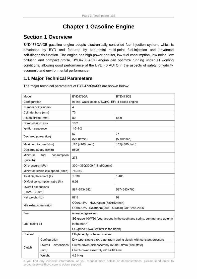
Section 1 Overview BYD473QA/QB gasoline engine adopts electronically controlled fuel injection system, which is developed by BYD and featured by sequential multi-point fuel-injection and advanced self-diagnosis function. The engine has high power per liter, low fuel consumption, low noise, low pollution and compact profile. BYD473QA/QB engine can optimize running under all working conditions, allowing good performance of the BYD F3 AUTO in the aspects of safety, drivability, economic and environmental performance.
1.1 Major Technical Parameters The major technical parameters of BYD473QA/QB are shown below: Model BYD473QA BYD473QB
Configuration In-line, water-cooled, SOHC, EFI, 4-stroke engine
Number of Cylinders 4
Cylinder bore (mm) 73
Piston stroke (mm) 80 88.9
Compression ratio 10.2
Ignition sequence 1-3-4-2
Declared power (kw) 67
(5800r/min)
75
(5800r/min)
Maximum torque (N.m) 120 (4700 r/min) 135(4800r/min)
Declared speed (r/min) 5800
Minimum fuel consumption
(g/kW·h) 275
Oil pressure (kPa) 300~350(3000r/min±50r/min)
Minimum stable idle speed (r/min) 780±50
Total displacement (L) 1.339 1.488
Oil/fuel consumption ratio (%) 0.26
Overall dimensions
(L×W×H) (mm) 587×543×682 587×543×700
Net weight (kg) 87.5 92
Idle exhaust emission CO≤0.15% HC≤40ppm (780±50r/min)
CO≤0.15% HC≤40ppm(2000±50r/min) GB18285-2005
Fuel unleaded gasoline
Lubricating oil
SG grade 10W/30 (year around in the south and spring, summer and autumn
in the north)
SG grade 5W/30 (winter in the north)
Coolant Ethylene glycol based coolant
Configuration Dry-type, single-disk, diaphragm spring clutch, with constant pressure
Overall dimensions
(mm)
Clutch driven disk assembly φ200×8.9mm (free state)
Clutch cover assembly φ255×40.4mm Clutch
Weight 4.314kg
Page 4, Total pages 119
If you find any incorrect information, or you request more details or demonstrations, please send email to [email protected] to obtain support.
Configuration Synchromesh transmission, 5 forward gears, 1 reverse gear
1st gear 3.308
2nd gear 1.826
3rd gear 1.207
4th gear 0.939
5th gear 0.730
Gear ratio
Reverse 3.231
Final drive ratio 4.471
Overall dimensions
(mm)
(L×W×H) 504×382×363mm
Gearbox
Lubricating oil Gear oil for medium duty vehicle (GL-4 SAE 80W/90)
1.2 Technical Parameters for Maintenance Cylinder Head
Part Name Measured Item Measuring
Condition Standard Value Service limit
Warping 0.08mm Cylinder head
Height 119.9~120.1mm
Camshaft axial clearance 0.05~0.25mm 0.5mm
Camshaft-bracket oil film clearance 0.045~0.084mm 0.1mm
Total runout Maximum 0.03mm 0.04mm
Intake 35.38mm
Camshaft
Cam lobe lift Exhaust 35.377mm
Intake 0.15~0.18mm Clearance (cold)
Exhaust 0.23~0.28mm
Intake 5.470~5.485mm 5.45mm Tappet outer diameter
Exhaust 5.455~5.470mm 5.42mm
Intake 0.025~0.060mm 0.08mm
Valve
Tappet-guide clearance Exhaust 0.04~0.075mm 0.11mm
Intake 0.85~1.15mm 1.60mm Width
Exhaust 1.25~1.55mm 2.00mm
Intake 46.1~46.5mm 46.8mm Valve seat
Tappet installation height Exhaust 46.2~46.6mm 46.9mm
Intake 50.5mm Valve spring Free length
Exhaust 57.2mm
Intake 5.51~5.53mm 5.55mm Inner diameter
Exhaust 5.51~5.53mm 5.55mm
Intake 15.85~16.35mm Valve guide
Installation height Exhaust 15.85~16.35mm
Intake 0.02~0.054mm 0.08mm Rocker arm
Rocker arm-rocker arm shaft
clearance Exhaust 0.02~0.054mm 0.08mm
Page 5, Total pages 119
If you find any incorrect information, or you request more details or demonstrations, please send email to [email protected] to obtain support.
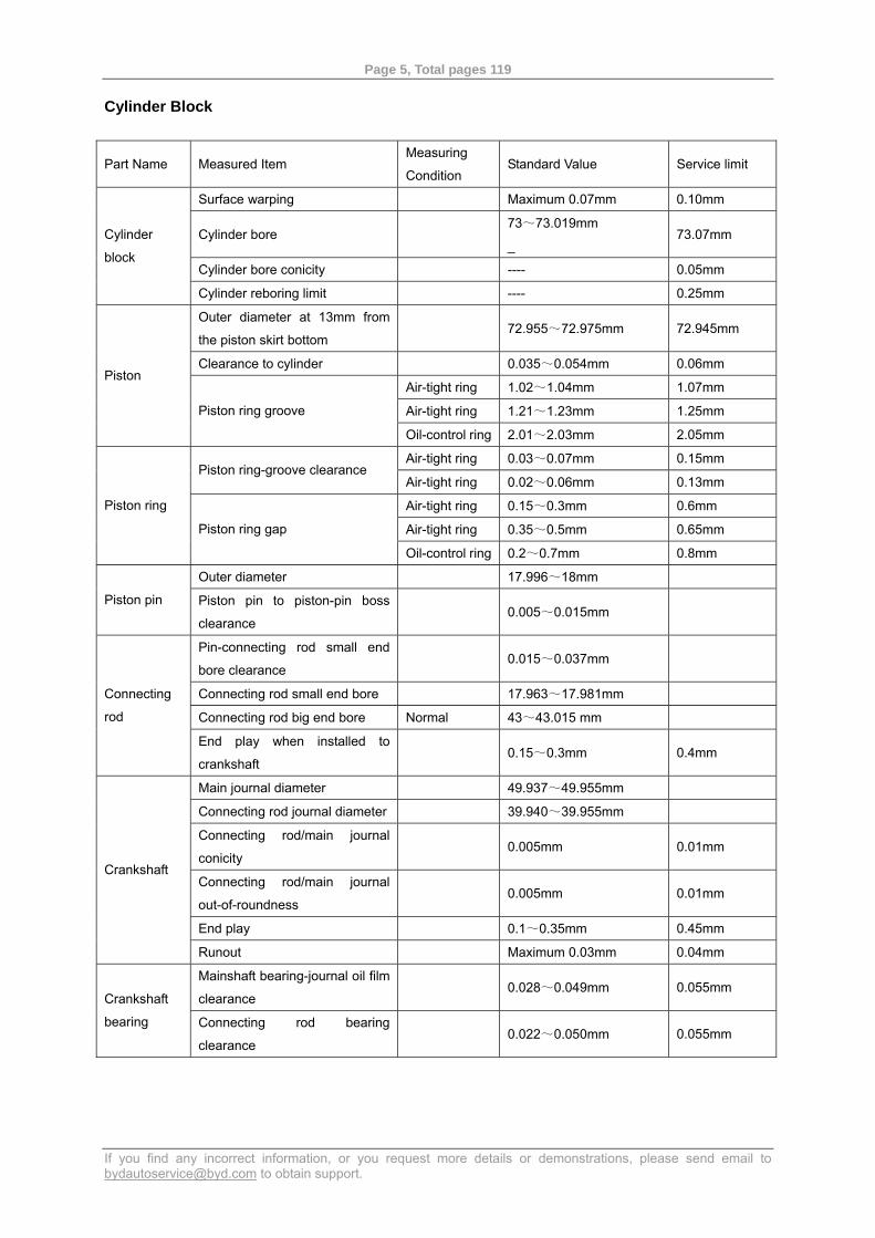
Cylinder Block
Part Name Measured Item Measuring
Condition Standard Value Service limit
Surface warping Maximum 0.07mm 0.10mm
Cylinder bore 73~73.019mm
_ 73.07mm
Cylinder bore conicity ---- 0.05mm
Cylinder
block
Cylinder reboring limit ---- 0.25mm
Outer diameter at 13mm from
the piston skirt bottom 72.955~72.975mm 72.945mm
Clearance to cylinder 0.035~0.054mm 0.06mm
Air-tight ring 1.02~1.04mm 1.07mm
Air-tight ring 1.21~1.23mm 1.25mm
Piston
Piston ring groove
Oil-control ring 2.01~2.03mm 2.05mm
Air-tight ring 0.03~0.07mm 0.15mm Piston ring-groove clearance
Air-tight ring 0.02~0.06mm 0.13mm
Air-tight ring 0.15~0.3mm 0.6mm
Air-tight ring 0.35~0.5mm 0.65mm
Piston ring
Piston ring gap
Oil-control ring 0.2~0.7mm 0.8mm
Outer diameter 17.996~18mm
Piston pin Piston pin to piston-pin boss
clearance 0.005~0.015mm
Pin-connecting rod small end
bore clearance 0.015~0.037mm
Connecting rod small end bore 17.963~17.981mm
Connecting rod big end bore Normal 43~43.015 mm
Connecting
rod
End play when installed to
crankshaft 0.15~0.3mm 0.4mm
Main journal diameter 49.937~49.955mm
Connecting rod journal diameter 39.940~39.955mm
Connecting rod/main journal
conicity 0.005mm 0.01mm
Connecting rod/main journal
out-of-roundness 0.005mm 0.01mm
End play 0.1~0.35mm 0.45mm
Crankshaft
Runout Maximum 0.03mm 0.04mm
Mainshaft bearing-journal oil film
clearance 0.028~0.049mm 0.055mm
Crankshaft
bearing Connecting rod bearing
clearance 0.022~0.050mm 0.055mm
Page 6, Total pages 119
If you find any incorrect information, or you request more details or demonstrations, please send email to [email protected] to obtain support.
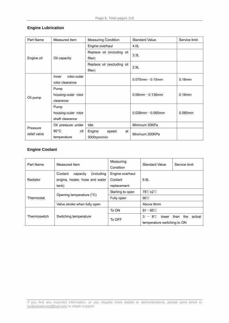
Engine Lubrication Part Name Measured Item Measuring Condition Standard Value Service limit
Engine overhaul 4.0L
Replace oil (including oil
filter) 3.3L
Engine oil Oil capacity
Replace oil (excluding oil
filter) 2.9L
Inner rotor-outer
rotor clearance 0.075mm~0.15mm 0.18mm
Pump
housing-outer rotor
clearance
0.06mm~0.136mm 0.18mm Oil pump
Pump
housing-outer rotor
shaft clearance
0.028mm~0.065mm 0.085mm
Idle Minimum 30KPa Pressure
relief valve
Oil pressure under
80°C oil
temperature
Engine speed at
3000rpm/min Minimum 300KPa
Engine Coolant
Part Name Measured Item Measuring
Condition Standard Value Service limit
Radiator
Coolant capacity (including
engine, heater, hose and water
tank)
Engine overhaul
Coolant
replacement
6.8L
Starting to open 78 ±2℃ ℃ Opening temperature (°C)
Fully open 90℃ Thermostat
Valve stroke when fully open Above 8mm
To ON 91~95℃
Thermoswitch Switching temperature To OFF
3 ~ 8 lower than the actual ℃
temperature switching to ON
Page 7, Total pages 119
If you find any incorrect information, or you request more details or demonstrations, please send email to [email protected] to obtain support.
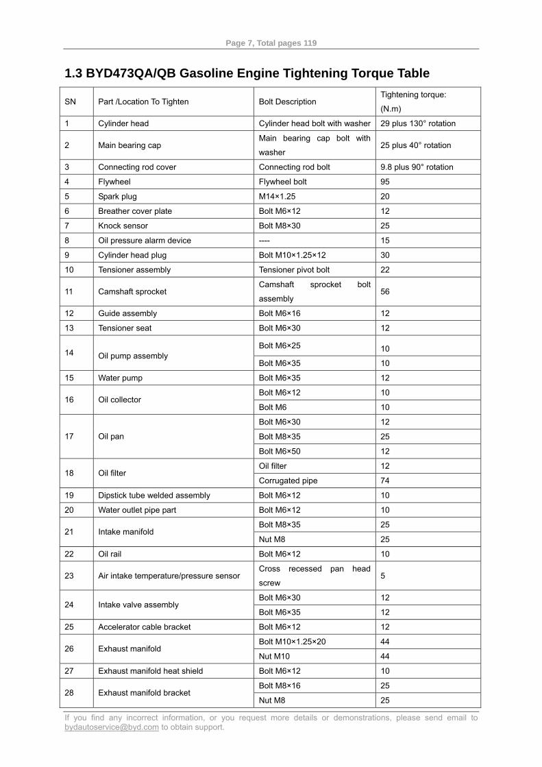
1.3 BYD473QA/QB Gasoline Engine Tightening Torque Table
SN Part /Location To Tighten Bolt Description Tightening torque:
(N.m)
1 Cylinder head Cylinder head bolt with washer 29 plus 130° rotation
2 Main bearing cap Main bearing cap bolt with
washer 25 plus 40° rotation
3 Connecting rod cover Connecting rod bolt 9.8 plus 90° rotation
4 Flywheel Flywheel bolt 95
5 Spark plug M14×1.25 20
6 Breather cover plate Bolt M6×12 12
7 Knock sensor Bolt M8×30 25
8 Oil pressure alarm device ---- 15
9 Cylinder head plug Bolt M10×1.25×12 30
10 Tensioner assembly Tensioner pivot bolt 22
11 Camshaft sprocket Camshaft sprocket bolt
assembly 56
12 Guide assembly Bolt M6×16 12
13 Tensioner seat Bolt M6×30 12
Bolt M6×25 10 14 Oil pump assembly Bolt M6×35 10
15 Water pump Bolt M6×35 12
Bolt M6×12 10 16 Oil collector
Bolt M6 10
Bolt M6×30 12
Bolt M8×35 25 17 Oil pan
Bolt M6×50 12
Oil filter 12 18 Oil filter
Corrugated pipe 74
19 Dipstick tube welded assembly Bolt M6×12 10
20 Water outlet pipe part Bolt M6×12 10
Bolt M8×35 25 21 Intake manifold
Nut M8 25
22 Oil rail Bolt M6×12 10
23 Air intake temperature/pressure sensor Cross recessed pan head
screw 5
Bolt M6×30 12 24 Intake valve assembly
Bolt M6×35 12
25 Accelerator cable bracket Bolt M6×12 12
Bolt M10×1.25×20 44 26 Exhaust manifold
Nut M10 44
27 Exhaust manifold heat shield Bolt M6×12 10
Bolt M8×16 25 28 Exhaust manifold bracket
Nut M8 25
Page 8, Total pages 119
If you find any incorrect information, or you request more details or demonstrations, please send email to [email protected] to obtain support.
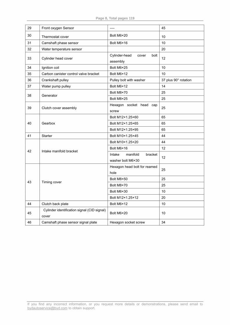
29 Front oxygen Sensor ---- 45
30 Thermostat cover Bolt M6×20 10
31 Camshaft phase sensor Bolt M6×16 10
32 Water temperature sensor 20
33 Cylinder head cover Cylinder-head cover bolt
assembly 12
34 Ignition coil Bolt M6×25 10
35 Carbon canister control valve bracket Bolt M6×12 10
36 Crankshaft pulley Pulley bolt with washer 37 plus 90° rotation
37 Water pump pulley Bolt M6×12 14
Bolt M8×70 25 38 Generator
Bolt M8×25 25
39 Clutch cover assembly Hexagon socket head cap
screw 25
Bolt M12×1.25×60 65
Bolt M12×1.25×65 65 40 Gearbox
Bolt M12×1.25×95 65
41 Starter Bolt M10×1.25×45 44
Bolt M10×1.25×20 44
Bolt M6×16 12 42 Intake manifold bracket
Intake manifold bracket
washer bolt M6×30 12
Hexagon head bolt for reamed
hole 25
Bolt M8×50 25
Bolt M8×70 25
Bolt M6×30 10
43 Timing cover
Bolt M12×1.25×12 20
44 Clutch back plate Bolt M6×12 10
45 Cylinder identification signal (CID signal)
cover Bolt M6×20 10
46 Camshaft phase sensor signal plate Hexagon socket screw 34
Page 9, Total pages 119
If you find any incorrect information, or you request more details or demonstrations, please send email to [email protected] to obtain support.
1.4 BYD473Q Engine Special-purpose Part List Model
Part No.
Part Name
BYD473QA BYD473QB
Cylinder block assembly BYD473QA-1002100 BYD473QB-1002100
Main bearing cap assembly BYD473QA-1002300 BYD473QB-1002300
Timing cover BYD473QA-1002031 BYD473QB-1002031
Fractured connecting rods N/A BYD473QB-1004030
Machined connecting rod part BYD473QA-1004030 N/A
Crankshaft BYD473QA-1005021 BYD473QB-1005021
Exhaust manifold bracket BYD473QA-1008032 BYD473QB-1008032
Guide assembly BYD473QA-1021020 BYD473QB-1021020
Tensioner assembly BYD473QA-1021030 BYD473QB-1021030
Silent timing chain assembly BYD473QA-1021040 BYD473QB-1021040
Tensioner seat BYD473QA-1021061 BYD473QB-1021061
Section 2 Cylinder Head
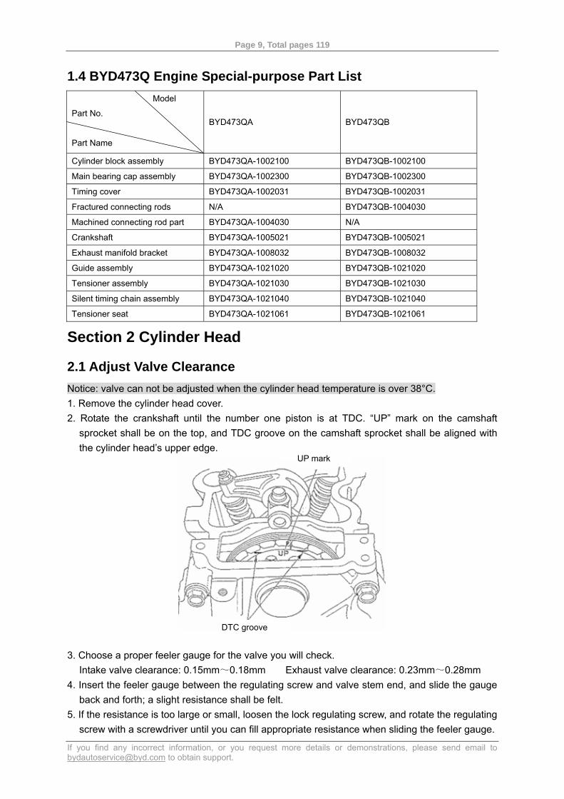
2.1 Adjust Valve Clearance Notice: valve can not be adjusted when the cylinder head temperature is over 38°C. 1. Remove the cylinder head cover. 2. Rotate the crankshaft until the number one piston is at TDC. “UP” mark on the camshaft
sprocket shall be on the top, and TDC groove on the camshaft sprocket shall be aligned with the cylinder head’s upper edge.
3. Choose a proper feeler gauge for the valve you will check. Intake valve clearance: 0.15mm~0.18mm Exhaust valve clearance: 0.23mm~0.28mm
4. Insert the feeler gauge between the regulating screw and valve stem end, and slide the gauge back and forth; a slight resistance shall be felt.
5. If the resistance is too large or small, loosen the lock regulating screw, and rotate the regulating screw with a screwdriver until you can fill appropriate resistance when sliding the feeler gauge.
UP mark
DTC groove
Page 10, Total pages 119
If you find any incorrect information, or you request more details or demonstrations, please send email to [email protected] to obtain support.
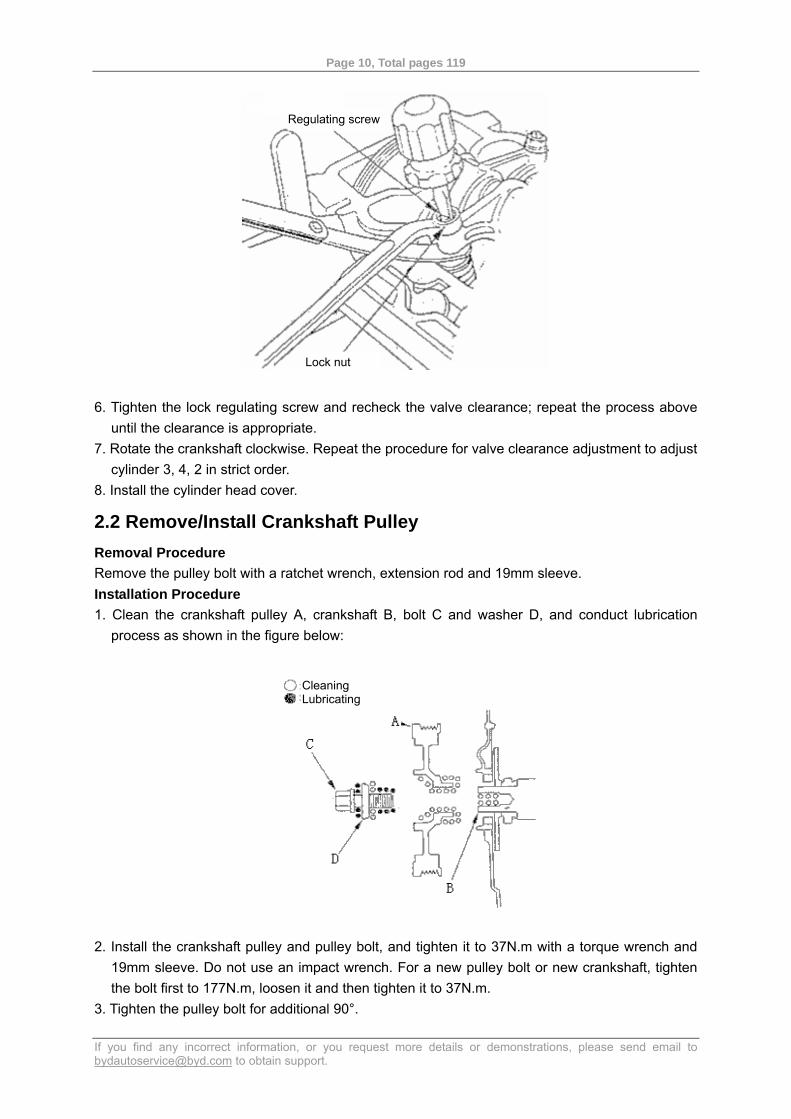
6. Tighten the lock regulating screw and recheck the valve clearance; repeat the process above until the clearance is appropriate.
7. Rotate the crankshaft clockwise. Repeat the procedure for valve clearance adjustment to adjust cylinder 3, 4, 2 in strict order.
8. Install the cylinder head cover.
2.2 Remove/Install Crankshaft Pulley Removal Procedure Remove the pulley bolt with a ratchet wrench, extension rod and 19mm sleeve. Installation Procedure 1. Clean the crankshaft pulley A, crankshaft B, bolt C and washer D, and conduct lubrication
process as shown in the figure below:
2. Install the crankshaft pulley and pulley bolt, and tighten it to 37N.m with a torque wrench and 19mm sleeve. Do not use an impact wrench. For a new pulley bolt or new crankshaft, tighten the bolt first to 177N.m, loosen it and then tighten it to 37N.m.
3. Tighten the pulley bolt for additional 90°.
Regulating screw
Lock nut
Cleaning Lubricating
Page 11, Total pages 119
If you find any incorrect information, or you request more details or demonstrations, please send email to [email protected] to obtain support.
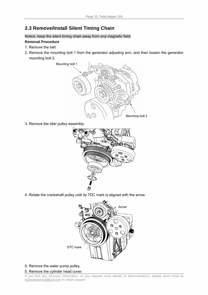
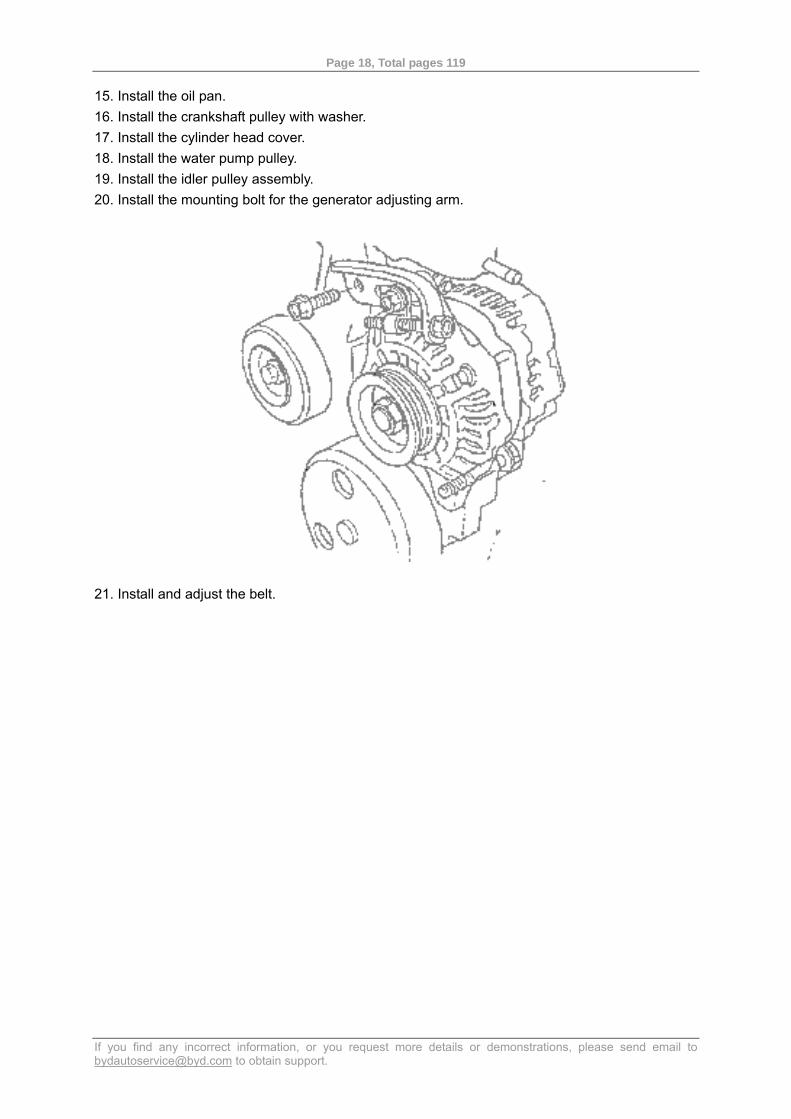
2.3 Remove/Install Silent Timing Chain Notice: keep the silent timing chain away from any magnetic field. Removal Procedure 1. Remove the belt. 2. Remove the mounting bolt 1 from the generator adjusting arm, and then loosen the generator
mounting bolt 2.
3. Remove the idler pulley assembly.
4. Rotate the crankshaft pulley until its TDC mark is aligned with the arrow.
5. Remove the water pump pulley. 5. Remove the cylinder head cover.
Mounting bolt 1
Mounting bolt 2
Arrow
DTC mark
Page 12, Total pages 119
If you find any incorrect information, or you request more details or demonstrations, please send email to [email protected] to obtain support.
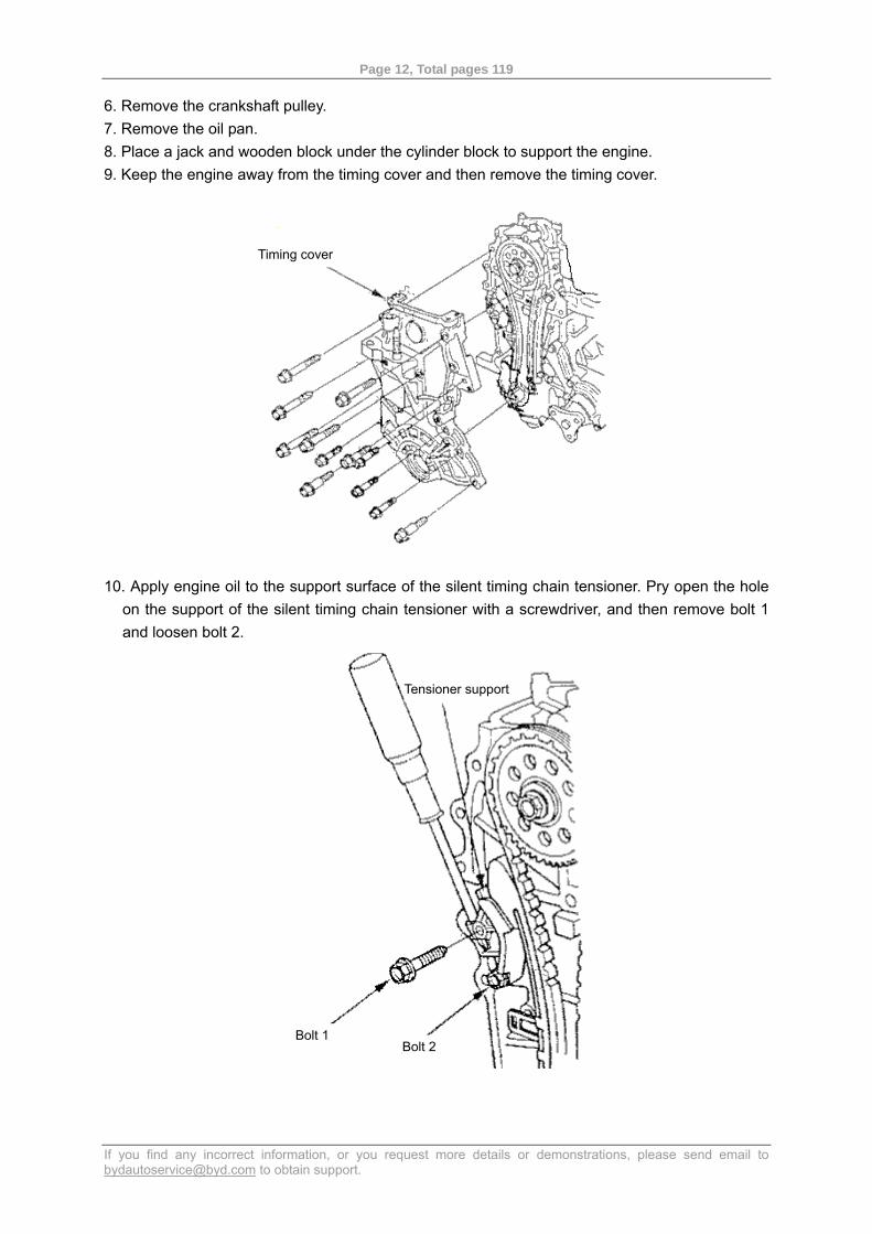
6. Remove the crankshaft pulley. 7. Remove the oil pan. 8. Place a jack and wooden block under the cylinder block to support the engine. 9. Keep the engine away from the timing cover and then remove the timing cover.
10. Apply engine oil to the support surface of the silent timing chain tensioner. Pry open the hole on the support of the silent timing chain tensioner with a screwdriver, and then remove bolt 1 and loosen bolt 2.
Timing cover
Tensioner support
Bolt 1 Bolt 2
Page 13, Total pages 119
If you find any incorrect information, or you request more details or demonstrations, please send email to [email protected] to obtain support.
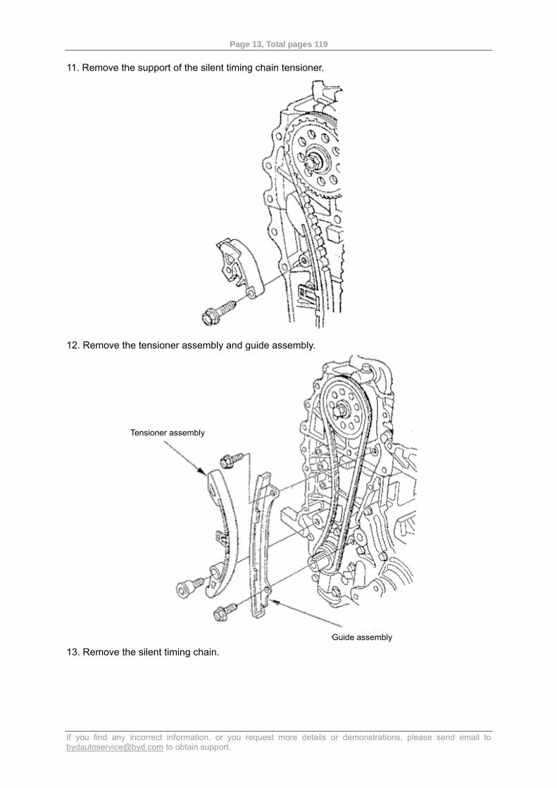
11. Remove the support of the silent timing chain tensioner.
12. Remove the tensioner assembly and guide assembly.
13. Remove the silent timing chain.
Tensioner assembly
Guide assembly
Page 14, Total pages 119
If you find any incorrect information, or you request more details or demonstrations, please send email to [email protected] to obtain support.
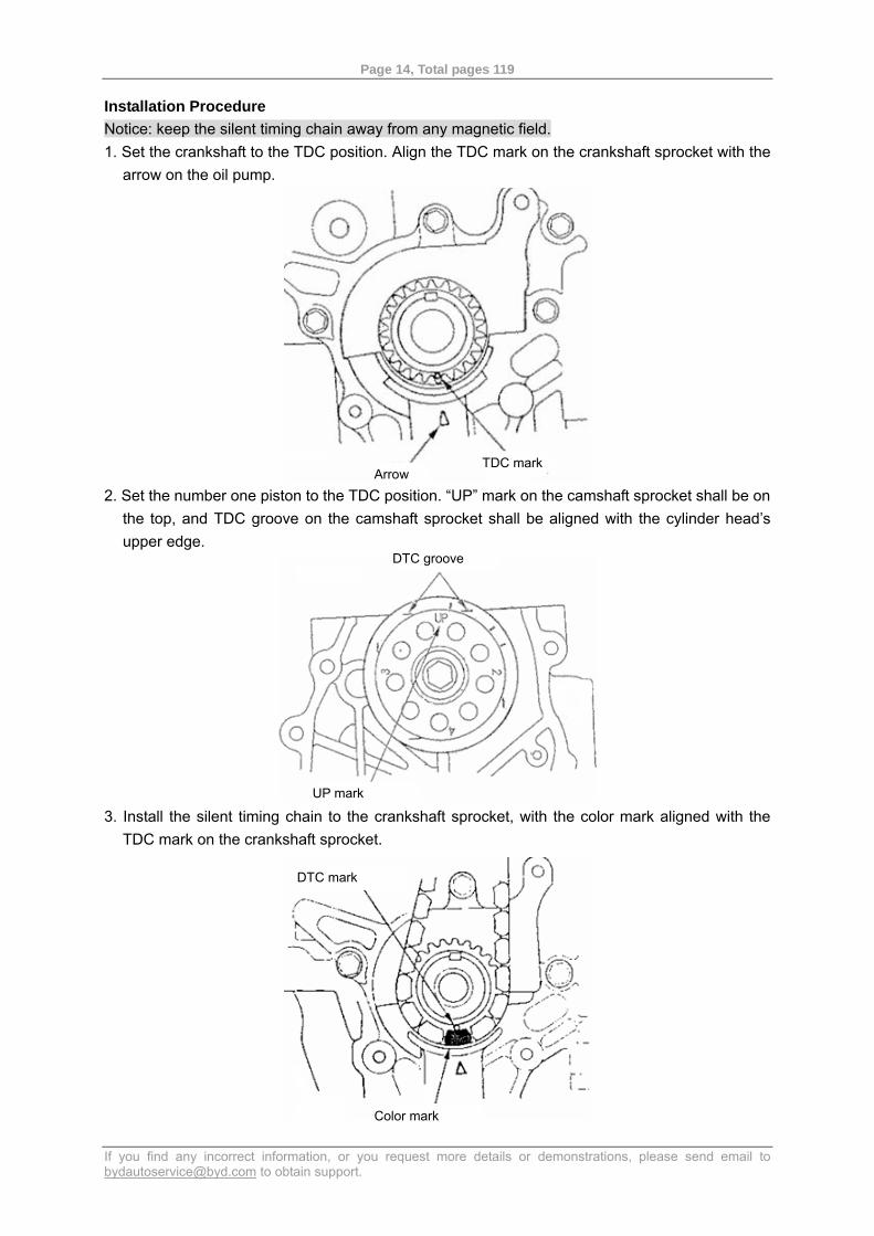
Installation Procedure Notice: keep the silent timing chain away from any magnetic field. 1. Set the crankshaft to the TDC position. Align the TDC mark on the crankshaft sprocket with the
arrow on the oil pump.
2. Set the number one piston to the TDC position. “UP” mark on the camshaft sprocket shall be on
the top, and TDC groove on the camshaft sprocket shall be aligned with the cylinder head’s upper edge.
3. Install the silent timing chain to the crankshaft sprocket, with the color mark aligned with the
TDC mark on the crankshaft sprocket.
Arrow TDC mark
DTC groove
UP mark
DTC mark
Color mark
Page 15, Total pages 119
If you find any incorrect information, or you request more details or demonstrations, please send email to [email protected] to obtain support.
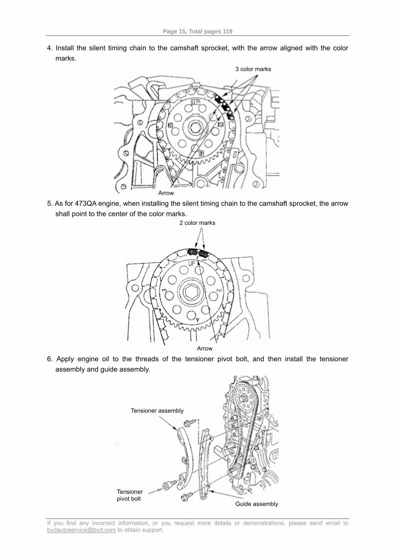
4. Install the silent timing chain to the camshaft sprocket, with the arrow aligned with the color marks.
5. As for 473QA engine, when installing the silent timing chain to the camshaft sprocket, the arrow
shall point to the center of the color marks.
6. Apply engine oil to the threads of the tensioner pivot bolt, and then install the tensioner
assembly and guide assembly.
3 color marks
Arrow
2 color marks
Arrow
Tensioner assembly
Guide assembly
Tensioner pivot bolt

Page 16, Total pages 119
If you find any incorrect information, or you request more details or demonstrations, please send email to [email protected] to obtain support.
7. Install the tensioner support and tighten the bolt slightly.
8. Apply engine oil to the sliding surface of the tensioner support.
9. Rotate the tensioner support clockwise to press tight the tensioner assembly, and then install the other bolts to fix it.
10. Check whether the crankshaft front oil seal on the timing cover is damaged. Replace the crankshaft front oil seal if it is damaged.
11. Clear away the old sealant on the timing cover matching surface, bolt and bolt hole. 12. Clean the timing cover matching surface and dry it. 13. Evenly apply sealant to the matching surface between the timing cover and cylinder block and
on the female threads in the bolt holes.
Tensioner support
Page 17, Total pages 119
If you find any incorrect information, or you request more details or demonstrations, please send email to [email protected] to obtain support.
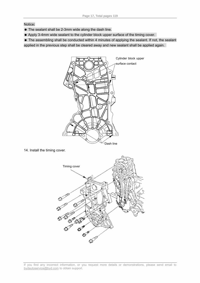
Notice: The sealant shall be 2-3mm wide along the dash line. Apply 3-4mm wide sealant to the cylinder block upper surface of the timing cover. The assembling shall be conducted within 4 minutes of applying the sealant. If not, the sealant
applied in the previous step shall be cleared away and new sealant shall be applied again.
14. Install the timing cover.
Cylinder block upper
surface contact
Dash line
Timing cover
Page 18, Total pages 119
If you find any incorrect information, or you request more details or demonstrations, please send email to [email protected] to obtain support.
15. Install the oil pan. 16. Install the crankshaft pulley with washer. 17. Install the cylinder head cover. 18. Install the water pump pulley. 19. Install the idler pulley assembly. 20. Install the mounting bolt for the generator adjusting arm.
21. Install and adjust the belt.
Page 19, Total pages 119
If you find any incorrect information, or you request more details or demonstrations, please send email to [email protected] to obtain support.
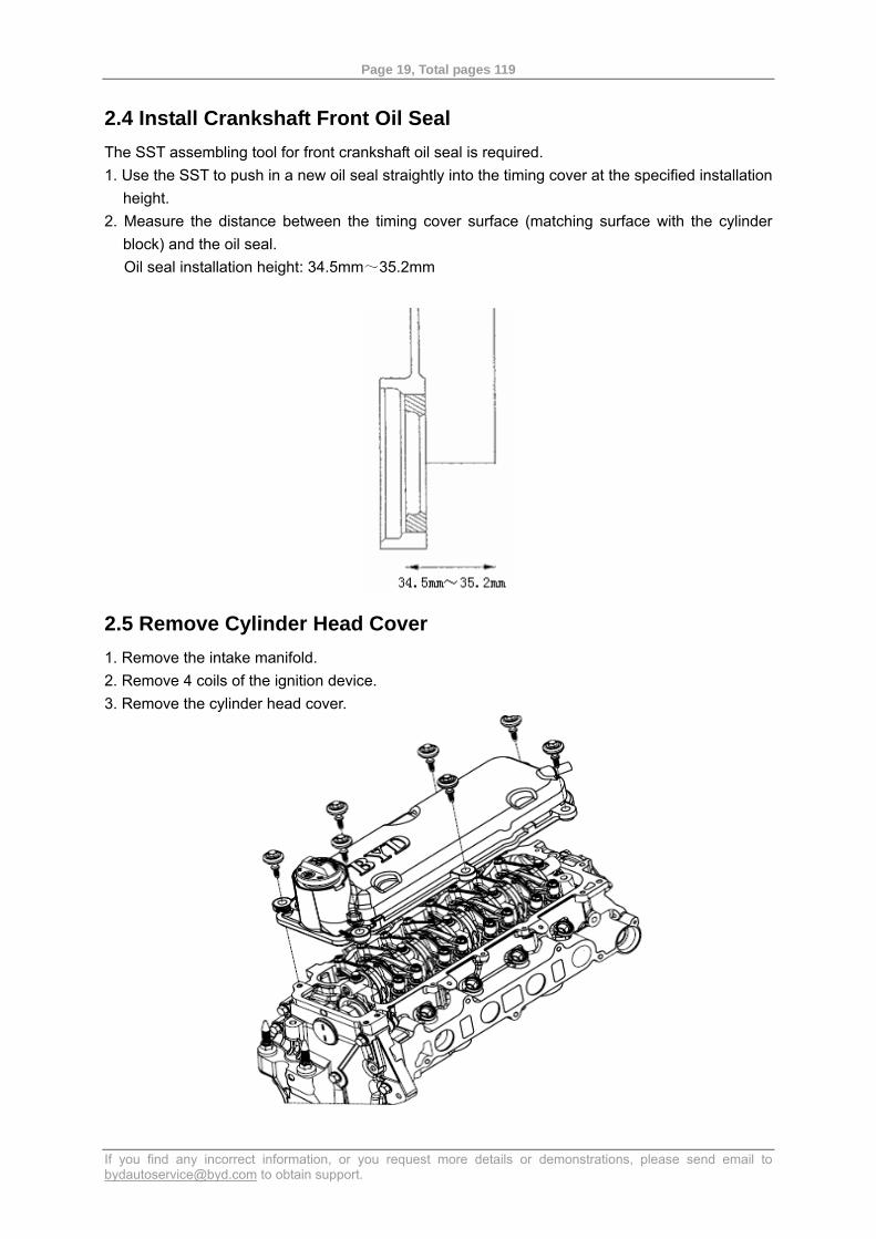
2.4 Install Crankshaft Front Oil Seal The SST assembling tool for front crankshaft oil seal is required. 1. Use the SST to push in a new oil seal straightly into the timing cover at the specified installation
height. 2. Measure the distance between the timing cover surface (matching surface with the cylinder
block) and the oil seal. Oil seal installation height: 34.5mm~35.2mm
2.5 Remove Cylinder Head Cover 1. Remove the intake manifold. 2. Remove 4 coils of the ignition device. 3. Remove the cylinder head cover.
Page 20, Total pages 119
If you find any incorrect information, or you request more details or demonstrations, please send email to [email protected] to obtain support.
2.6 Remove Cylinder Head Notice:
Use a fender cover to prevent damage to the paint surface. To prevent damage, hold the connector by the hard part and pull out the wire harness connector
carefully. To prevent damage to the cylinder head, do not loosen the bolts until the engine coolant
temperature is lower than 38 (100 ).℃ ℉ Make proper marks on all cables and hoses to prevent wrong connection. Make sure the cables
and hoses are not contacting each other or interfering with other parts. Keep the silent timing chain away from any magnetic field.
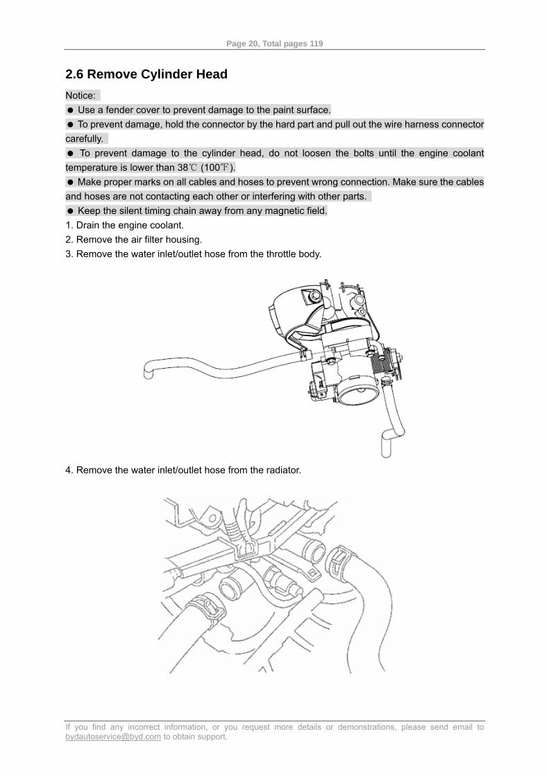
1. Drain the engine coolant. 2. Remove the air filter housing. 3. Remove the water inlet/outlet hose from the throttle body.
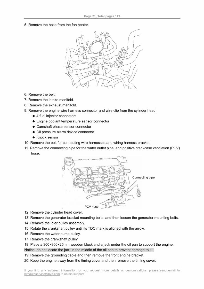
4. Remove the water inlet/outlet hose from the radiator.
Page 21, Total pages 119
If you find any incorrect information, or you request more details or demonstrations, please send email to [email protected] to obtain support.
5. Remove the hose from the fan heater.
6. Remove the belt. 7. Remove the intake manifold. 8. Remove the exhaust manifold. 9. Remove the engine wire harness connector and wire clip from the cylinder head.
4 fuel injector connectors Engine coolant temperature sensor connector Camshaft phase sensor connector Oil pressure alarm device connector Knock sensor
10. Remove the bolt for connecting wire harnesses and wiring harness bracket. 11. Remove the connecting pipe for the water outlet pipe, and positive crankcase ventilation (PCV)
hose.
12. Remove the cylinder head cover. 13. Remove the generator bracket mounting bolts, and then loosen the generator mounting bolts. 14. Remove the idler pulley assembly. 15. Rotate the crankshaft pulley until its TDC mark is aligned with the arrow. 16. Remove the water pump pulley. 17. Remove the crankshaft pulley. 18. Place a 300×300×25mm wooden block and a jack under the oil pan to support the engine. Notice: do not locate the jack in the middle of the oil pan to prevent damage to it. 19. Remove the grounding cable and then remove the front engine bracket. 20. Keep the engine away from the timing cover and then remove the timing cover.
Connecting pipe
PCV hose
Page 22, Total pages 119
If you find any incorrect information, or you request more details or demonstrations, please send email to [email protected] to obtain support.
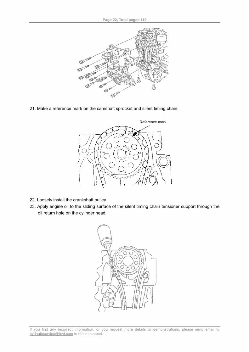
21. Make a reference mark on the camshaft sprocket and silent timing chain.
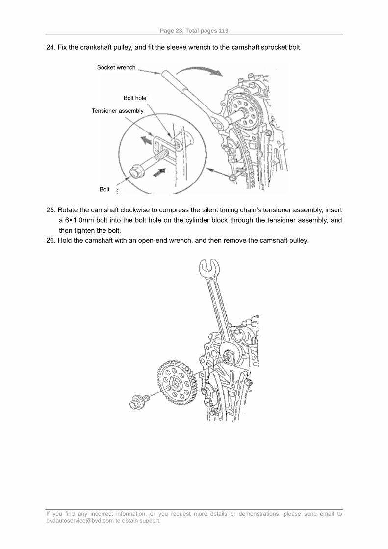
22. Loosely install the crankshaft pulley. 23. Apply engine oil to the sliding surface of the silent timing chain tensioner support through the
oil return hole on the cylinder head.
Reference mark
Page 23, Total pages 119
If you find any incorrect information, or you request more details or demonstrations, please send email to [email protected] to obtain support.
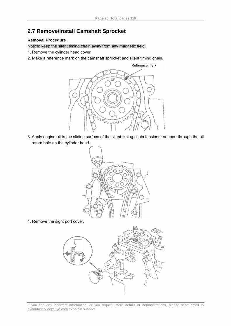
24. Fix the crankshaft pulley, and fit the sleeve wrench to the camshaft sprocket bolt.
25. Rotate the camshaft clockwise to compress the silent timing chain’s tensioner assembly, insert a 6×1.0mm bolt into the bolt hole on the cylinder block through the tensioner assembly, and then tighten the bolt.
26. Hold the camshaft with an open-end wrench, and then remove the camshaft pulley.
Socket wrench
Bolt hole
Bolt
Tensioner assembly
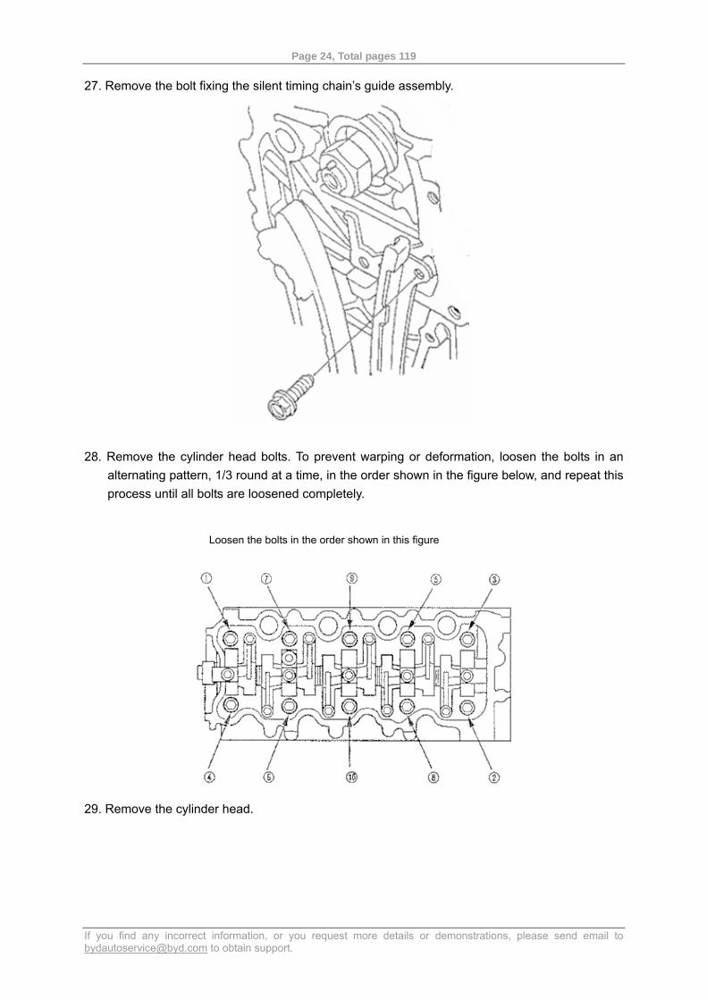
Page 24, Total pages 119
If you find any incorrect information, or you request more details or demonstrations, please send email to [email protected] to obtain support.
27. Remove the bolt fixing the silent timing chain’s guide assembly.
28. Remove the cylinder head bolts. To prevent warping or deformation, loosen the bolts in an
alternating pattern, 1/3 round at a time, in the order shown in the figure below, and repeat this process until all bolts are loosened completely.
29. Remove the cylinder head.
Loosen the bolts in the order shown in this figure
Page 25, Total pages 119
If you find any incorrect information, or you request more details or demonstrations, please send email to [email protected] to obtain support.
2.7 Remove/Install Camshaft Sprocket Removal Procedure Notice: keep the silent timing chain away from any magnetic field. 1. Remove the cylinder head cover. 2. Make a reference mark on the camshaft sprocket and silent timing chain.
3. Apply engine oil to the sliding surface of the silent timing chain tensioner support through the oil
return hole on the cylinder head.
4. Remove the sight port cover.
Reference mark
Page 26, Total pages 119
If you find any incorrect information, or you request more details or demonstrations, please send email to [email protected] to obtain support.
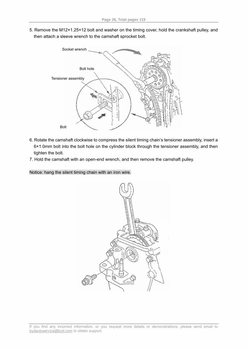
5. Remove the M12×1.25×12 bolt and washer on the timing cover, hold the crankshaft pulley, and then attach a sleeve wrench to the camshaft sprocket bolt.
6. Rotate the camshaft clockwise to compress the silent timing chain’s tensioner assembly, insert a 6×1.0mm bolt into the bolt hole on the cylinder block through the tensioner assembly, and then tighten the bolt.
7. Hold the camshaft with an open-end wrench, and then remove the camshaft pulley. Notice: hang the silent timing chain with an iron wire.
Bolt hole
Socket wrench
Tensioner assembly
Bolt
Page 27, Total pages 119
If you find any incorrect information, or you request more details or demonstrations, please send email to [email protected] to obtain support.
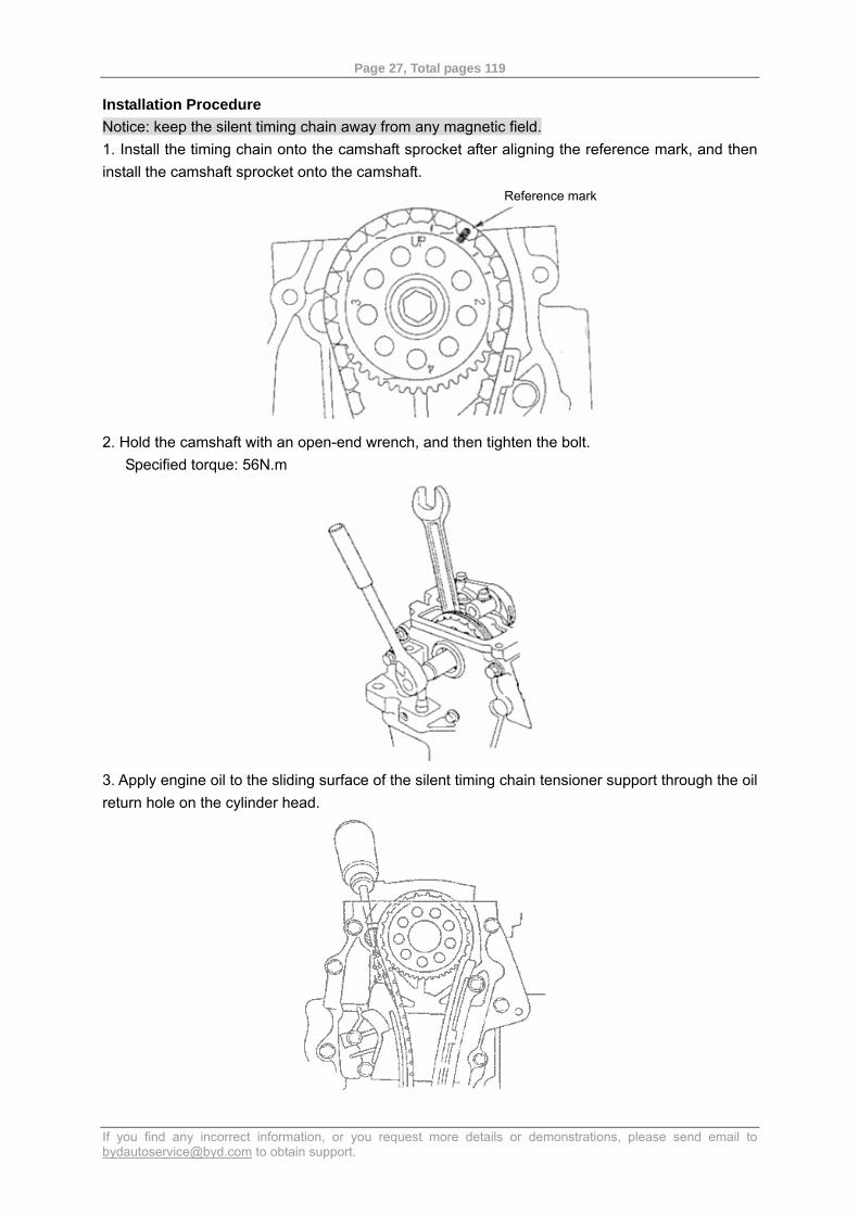
Installation Procedure Notice: keep the silent timing chain away from any magnetic field. 1. Install the timing chain onto the camshaft sprocket after aligning the reference mark, and then install the camshaft sprocket onto the camshaft.
2. Hold the camshaft with an open-end wrench, and then tighten the bolt. Specified torque: 56N.m
3. Apply engine oil to the sliding surface of the silent timing chain tensioner support through the oil return hole on the cylinder head.
Reference mark
Page 28, Total pages 119
If you find any incorrect information, or you request more details or demonstrations, please send email to [email protected] to obtain support.
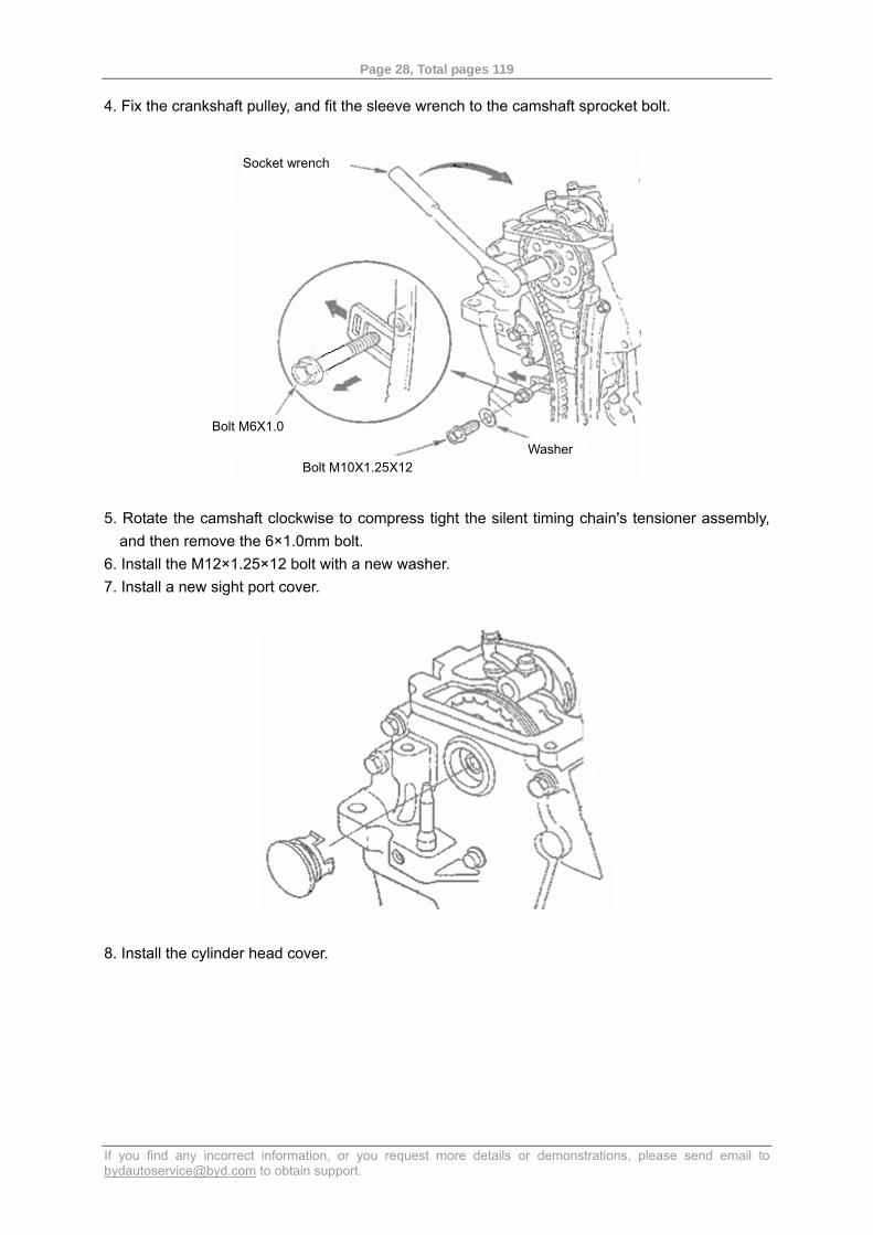
4. Fix the crankshaft pulley, and fit the sleeve wrench to the camshaft sprocket bolt.
5. Rotate the camshaft clockwise to compress tight the silent timing chain's tensioner assembly,
and then remove the 6×1.0mm bolt. 6. Install the M12×1.25×12 bolt with a new washer. 7. Install a new sight port cover.
8. Install the cylinder head cover.
Socket wrench
Bolt M6X1.0
Bolt M10X1.25X12 Washer
Page 29, Total pages 119
If you find any incorrect information, or you request more details or demonstrations, please send email to [email protected] to obtain support.
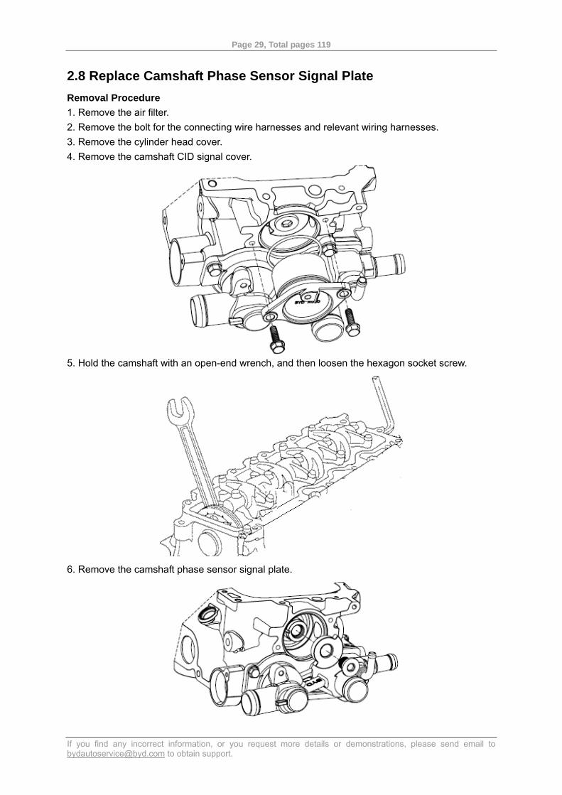
2.8 Replace Camshaft Phase Sensor Signal Plate Removal Procedure 1. Remove the air filter. 2. Remove the bolt for the connecting wire harnesses and relevant wiring harnesses. 3. Remove the cylinder head cover. 4. Remove the camshaft CID signal cover.
5. Hold the camshaft with an open-end wrench, and then loosen the hexagon socket screw.
6. Remove the camshaft phase sensor signal plate.
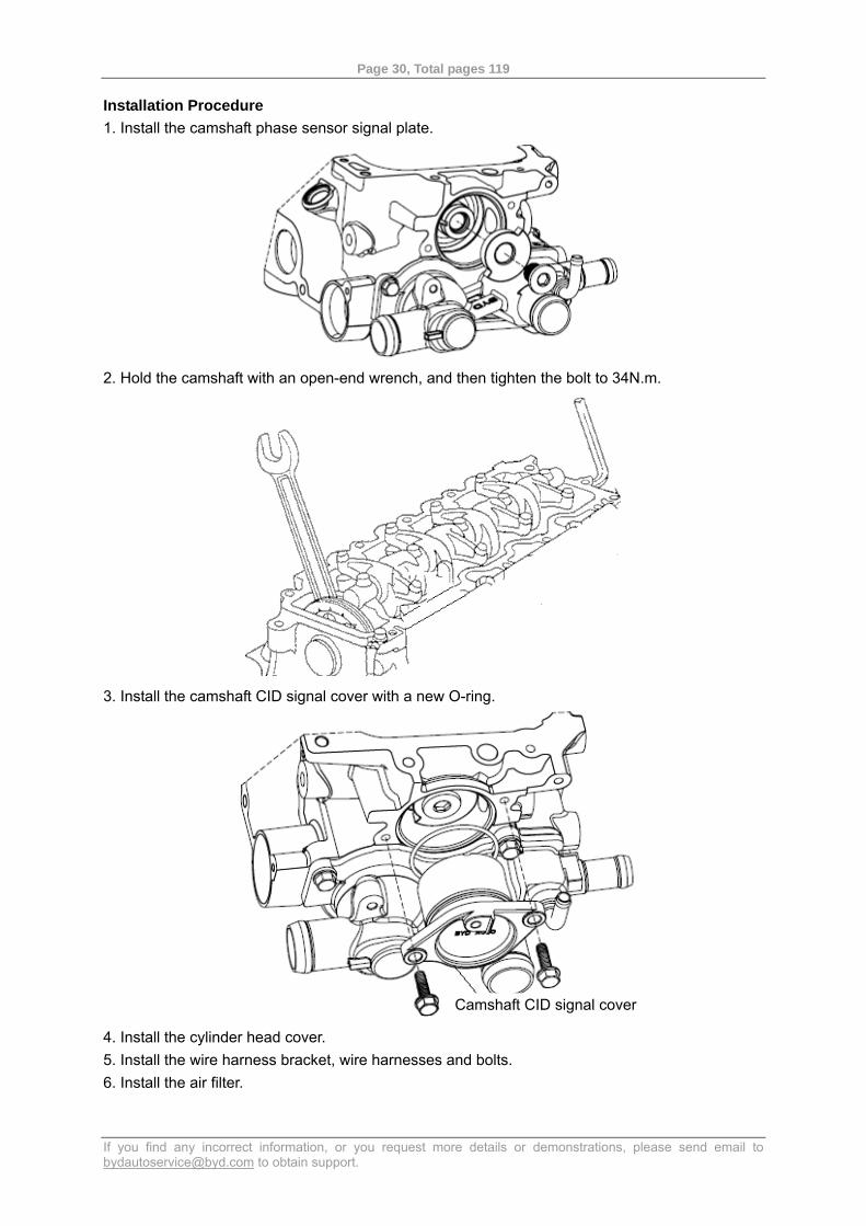
Page 30, Total pages 119
If you find any incorrect information, or you request more details or demonstrations, please send email to [email protected] to obtain support.
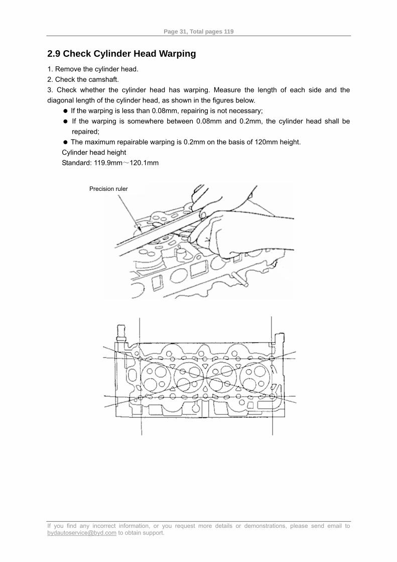
Installation Procedure 1. Install the camshaft phase sensor signal plate.
2. Hold the camshaft with an open-end wrench, and then tighten the bolt to 34N.m.
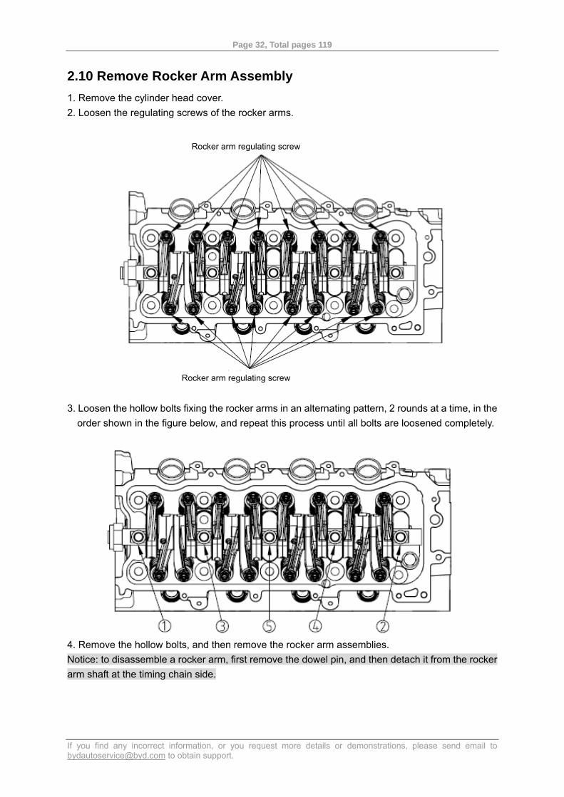
3. Install the camshaft CID signal cover with a new O-ring.
4. Install the cylinder head cover. 5. Install the wire harness bracket, wire harnesses and bolts. 6. Install the air filter.
Camshaft CID signal cover
Page 31, Total pages 119
If you find any incorrect information, or you request more details or demonstrations, please send email to [email protected] to obtain support.
2.9 Check Cylinder Head Warping 1. Remove the cylinder head. 2. Check the camshaft. 3. Check whether the cylinder head has warping. Measure the length of each side and the diagonal length of the cylinder head, as shown in the figures below.
If the warping is less than 0.08mm, repairing is not necessary; If the warping is somewhere between 0.08mm and 0.2mm, the cylinder head shall be repaired;
The maximum repairable warping is 0.2mm on the basis of 120mm height. Cylinder head height Standard: 119.9mm~120.1mm
Precision ruler
Page 32, Total pages 119
If you find any incorrect information, or you request more details or demonstrations, please send email to [email protected] to obtain support.
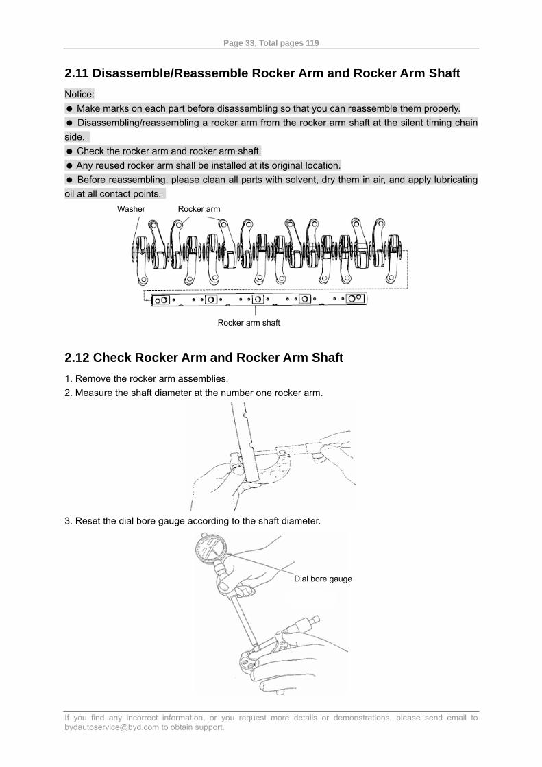
2.10 Remove Rocker Arm Assembly 1. Remove the cylinder head cover. 2. Loosen the regulating screws of the rocker arms.
3. Loosen the hollow bolts fixing the rocker arms in an alternating pattern, 2 rounds at a time, in the
order shown in the figure below, and repeat this process until all bolts are loosened completely.
4. Remove the hollow bolts, and then remove the rocker arm assemblies. Notice: to disassemble a rocker arm, first remove the dowel pin, and then detach it from the rocker arm shaft at the timing chain side.
Rocker arm regulating screw
Rocker arm regulating screw
Page 33, Total pages 119
If you find any incorrect information, or you request more details or demonstrations, please send email to [email protected] to obtain support.
2.11 Disassemble/Reassemble Rocker Arm and Rocker Arm Shaft Notice:
Make marks on each part before disassembling so that you can reassemble them properly. Disassembling/reassembling a rocker arm from the rocker arm shaft at the silent timing chain
side. Check the rocker arm and rocker arm shaft. Any reused rocker arm shall be installed at its original location. Before reassembling, please clean all parts with solvent, dry them in air, and apply lubricating
oil at all contact points.
2.12 Check Rocker Arm and Rocker Arm Shaft 1. Remove the rocker arm assemblies. 2. Measure the shaft diameter at the number one rocker arm.
3. Reset the dial bore gauge according to the shaft diameter.
Washer Rocker arm
Rocker arm shaft
Dial bore gauge
Page 34, Total pages 119
If you find any incorrect information, or you request more details or demonstrations, please send email to [email protected] to obtain support.
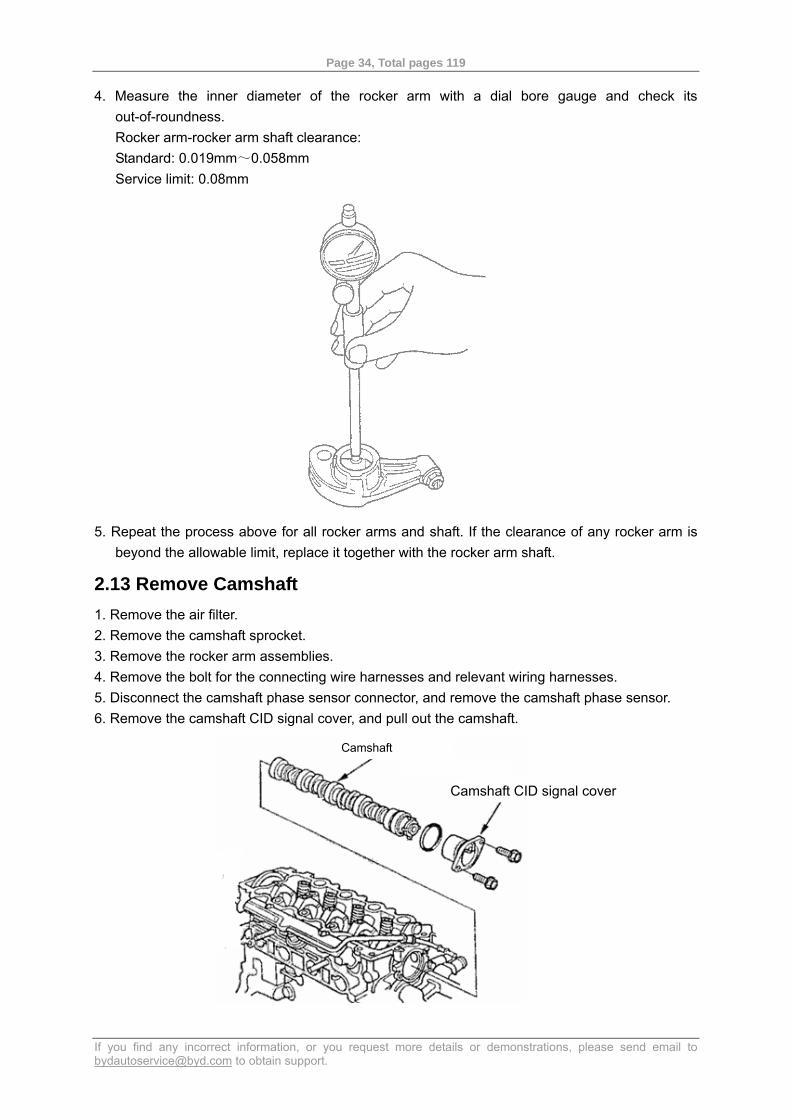
4. Measure the inner diameter of the rocker arm with a dial bore gauge and check its out-of-roundness. Rocker arm-rocker arm shaft clearance: Standard: 0.019mm~0.058mm Service limit: 0.08mm
5. Repeat the process above for all rocker arms and shaft. If the clearance of any rocker arm is beyond the allowable limit, replace it together with the rocker arm shaft.
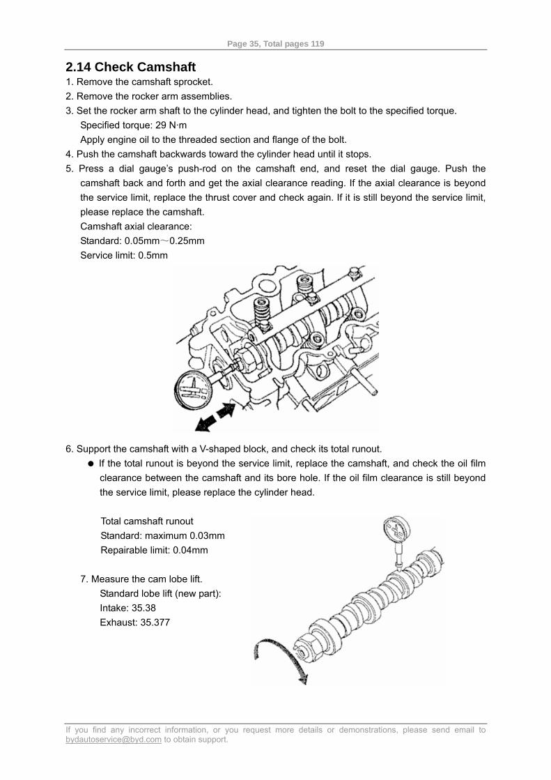
2.13 Remove Camshaft 1. Remove the air filter. 2. Remove the camshaft sprocket. 3. Remove the rocker arm assemblies. 4. Remove the bolt for the connecting wire harnesses and relevant wiring harnesses. 5. Disconnect the camshaft phase sensor connector, and remove the camshaft phase sensor. 6. Remove the camshaft CID signal cover, and pull out the camshaft.
Camshaft
Camshaft CID signal cover
Page 35, Total pages 119
If you find any incorrect information, or you request more details or demonstrations, please send email to [email protected] to obtain support.
2.14 Check Camshaft 1. Remove the camshaft sprocket. 2. Remove the rocker arm assemblies. 3. Set the rocker arm shaft to the cylinder head, and tighten the bolt to the specified torque.
Specified torque: 29 N·m Apply engine oil to the threaded section and flange of the bolt.
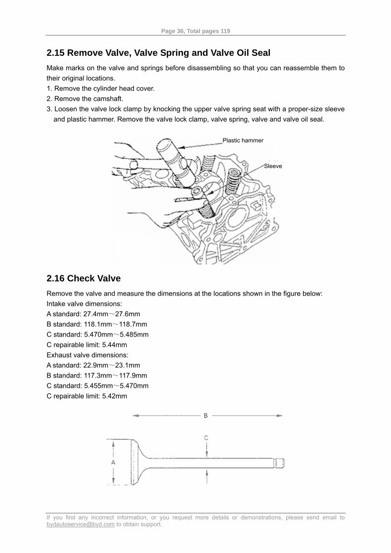
4. Push the camshaft backwards toward the cylinder head until it stops. 5. Press a dial gauge’s push-rod on the camshaft end, and reset the dial gauge. Push the
camshaft back and forth and get the axial clearance reading. If the axial clearance is beyond the service limit, replace the thrust cover and check again. If it is still beyond the service limit, please replace the camshaft. Camshaft axial clearance: Standard: 0.05mm~0.25mm Service limit: 0.5mm
6. Support the camshaft with a V-shaped block, and check its total runout. If the total runout is beyond the service limit, replace the camshaft, and check the oil film clearance between the camshaft and its bore hole. If the oil film clearance is still beyond the service limit, please replace the cylinder head.
Total camshaft runout Standard: maximum 0.03mm Repairable limit: 0.04mm
7. Measure the cam lobe lift.
Standard lobe lift (new part): Intake: 35.38 Exhaust: 35.377
Page 36, Total pages 119
If you find any incorrect information, or you request more details or demonstrations, please send email to [email protected] to obtain support.
2.15 Remove Valve, Valve Spring and Valve Oil Seal Make marks on the valve and springs before disassembling so that you can reassemble them to their original locations. 1. Remove the cylinder head cover. 2. Remove the camshaft. 3. Loosen the valve lock clamp by knocking the upper valve spring seat with a proper-size sleeve
and plastic hammer. Remove the valve lock clamp, valve spring, valve and valve oil seal.
2.16 Check Valve Remove the valve and measure the dimensions at the locations shown in the figure below: Intake valve dimensions: A standard: 27.4mm~27.6mm B standard: 118.1mm~118.7mm C standard: 5.470mm~5.485mm C repairable limit: 5.44mm Exhaust valve dimensions: A standard: 22.9mm~23.1mm B standard: 117.3mm~117.9mm C standard: 5.455mm~5.470mm C repairable limit: 5.42mm
Plastic hammer
Sleeve
Page 37, Total pages 119
If you find any incorrect information, or you request more details or demonstrations, please send email to [email protected] to obtain support.
2.17 Check Valve Tappet-Valve Guide Clearance 1. Remove the valve. 2. Slide out the valve from the guide for some 10mm, shake the valve tappet from the normal
thrust direction (shaking method) and then measure the inner diameter of the guide with a dial bore gauge, and the outer diameter of the tappet with a micrometer. The difference between the two measured values is the valve tappet-valve guide clearance.
If the result is beyond the service limit, install a new valve and measure the clearance again. If the new clearance is within the service limit, proceed with the reassembling process. Go to step 3 if the new clearance is still beyond the service limit.
Intake valve tappet-valve guide clearance: Standard: 0.04mm~0.10mm Service limit: 0.16mm Exhaust valve tappet-valve guide clearance: Standard: 0.10mm~0.16mm Service limit: 0.22mm
3. Measure the inner diameter of the valve guide and the outer diameter of the valve tappet at 3
different locations, using the devices mentioned in step 2, and then subtract the measured inner diameters by the outer diameters. The difference between the maximum inner diameter and the minimum outer diameter shall fall in the service limit. Intake valve tappet-valve guide clearance: Standard: 0.02mm~0.05mm Service limit: 0.08mm Exhaust valve tappet-valve guide clearance: Standard: 0.050mm~0.080mm Service limit: 0.11mm
Page 38, Total pages 119
If you find any incorrect information, or you request more details or demonstrations, please send email to [email protected] to obtain support.
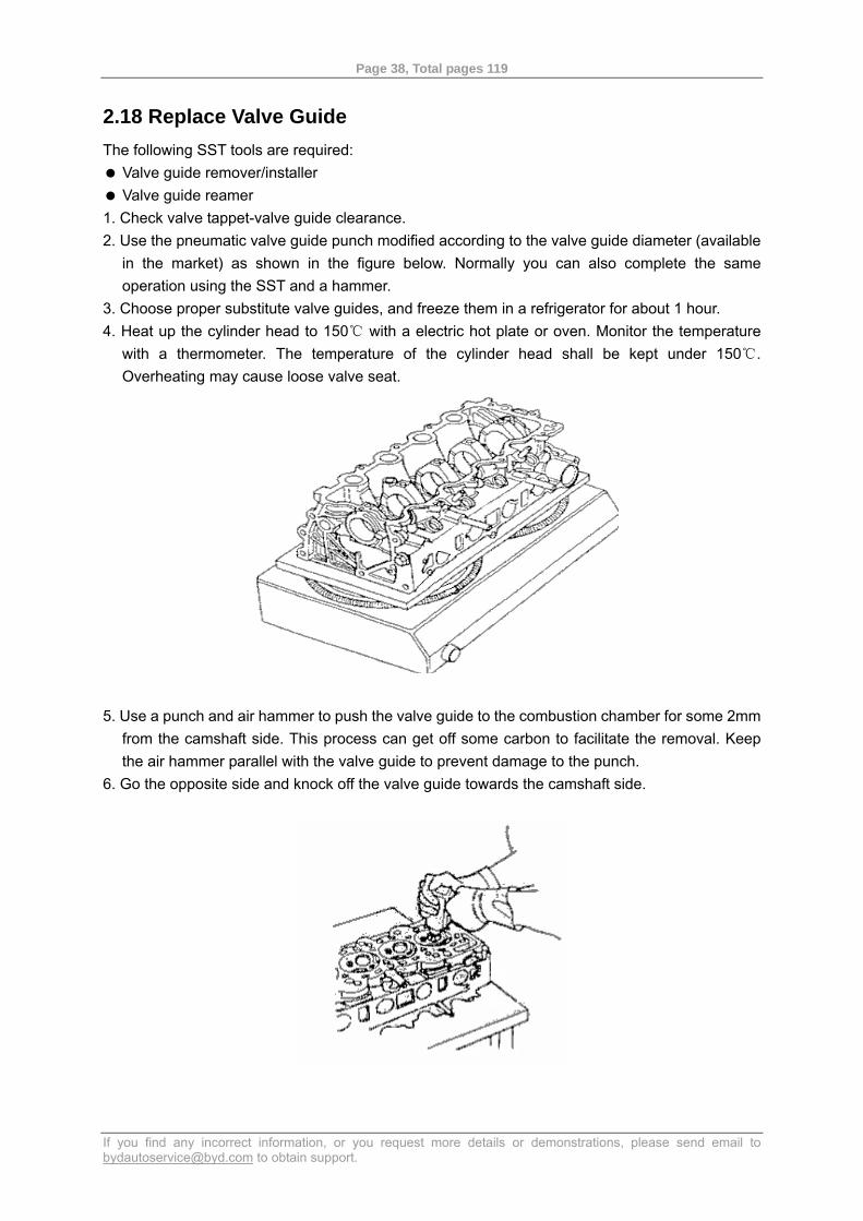
2.18 Replace Valve Guide The following SST tools are required:
Valve guide remover/installer Valve guide reamer
1. Check valve tappet-valve guide clearance. 2. Use the pneumatic valve guide punch modified according to the valve guide diameter (available
in the market) as shown in the figure below. Normally you can also complete the same operation using the SST and a hammer.
3. Choose proper substitute valve guides, and freeze them in a refrigerator for about 1 hour. 4. Heat up the cylinder head to 150 with a electric hot plate or oven. Monitor the temperature ℃
with a thermometer. The temperature of the cylinder head shall be kept under 150 . ℃
Overheating may cause loose valve seat.
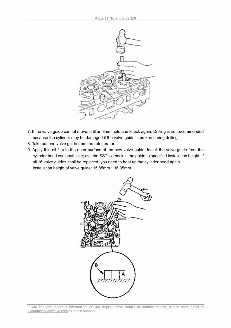
5. Use a punch and air hammer to push the valve guide to the combustion chamber for some 2mm
from the camshaft side. This process can get off some carbon to facilitate the removal. Keep the air hammer parallel with the valve guide to prevent damage to the punch.
6. Go the opposite side and knock off the valve guide towards the camshaft side.
Page 39, Total pages 119
If you find any incorrect information, or you request more details or demonstrations, please send email to [email protected] to obtain support.
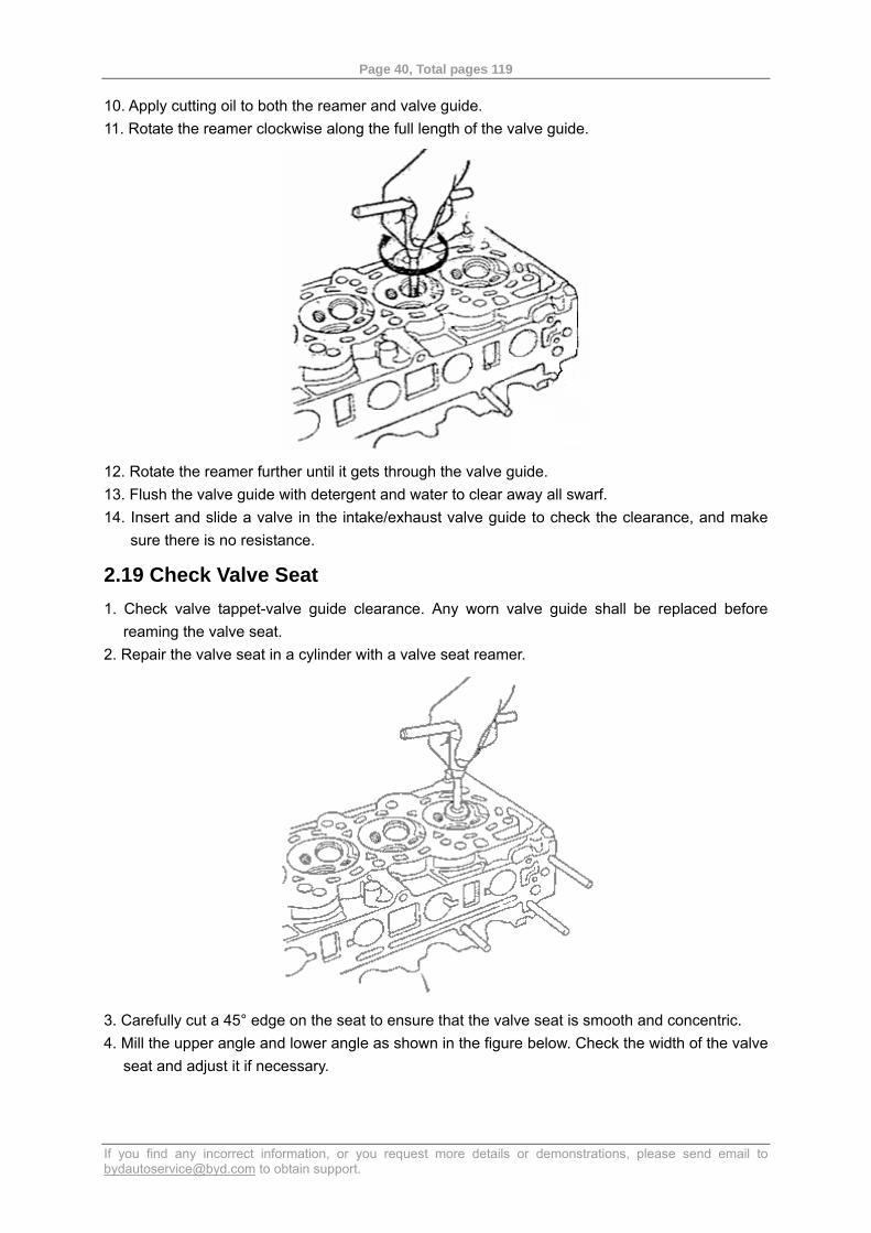
7. If the valve guide cannot move, drill an 8mm hole and knock again. Drilling is not recommended
because the cylinder may be damaged if the valve guide is broken during drilling. 8. Take out one valve guide from the refrigerator. 9. Apply thin oil film to the outer surface of the new valve guide. Install the valve guide from the
cylinder head camshaft side; use the SST to knock in the guide to specified installation height. If all 16 valve guides shall be replaced, you need to heat up the cylinder head again. Installation height of valve guide: 15.85mm~16.35mm
Page 40, Total pages 119
If you find any incorrect information, or you request more details or demonstrations, please send email to [email protected] to obtain support.
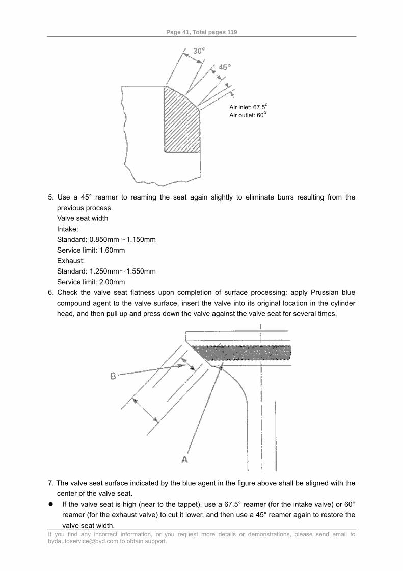
10. Apply cutting oil to both the reamer and valve guide. 11. Rotate the reamer clockwise along the full length of the valve guide.
12. Rotate the reamer further until it gets through the valve guide. 13. Flush the valve guide with detergent and water to clear away all swarf. 14. Insert and slide a valve in the intake/exhaust valve guide to check the clearance, and make
sure there is no resistance.
2.19 Check Valve Seat 1. Check valve tappet-valve guide clearance. Any worn valve guide shall be replaced before
reaming the valve seat. 2. Repair the valve seat in a cylinder with a valve seat reamer.
3. Carefully cut a 45° edge on the seat to ensure that the valve seat is smooth and concentric. 4. Mill the upper angle and lower angle as shown in the figure below. Check the width of the valve
seat and adjust it if necessary.
Page 41, Total pages 119
If you find any incorrect information, or you request more details or demonstrations, please send email to [email protected] to obtain support.
5. Use a 45° reamer to reaming the seat again slightly to eliminate burrs resulting from the
previous process. Valve seat width Intake: Standard: 0.850mm~1.150mm Service limit: 1.60mm Exhaust: Standard: 1.250mm~1.550mm Service limit: 2.00mm
6. Check the valve seat flatness upon completion of surface processing: apply Prussian blue compound agent to the valve surface, insert the valve into its original location in the cylinder head, and then pull up and press down the valve against the valve seat for several times.
7. The valve seat surface indicated by the blue agent in the figure above shall be aligned with the
center of the valve seat. If the valve seat is high (near to the tappet), use a 67.5° reamer (for the intake valve) or 60°
reamer (for the exhaust valve) to cut it lower, and then use a 45° reamer again to restore the valve seat width.
Air inlet: 67.5o
Air outlet: 60o
Page 42, Total pages 119
If you find any incorrect information, or you request more details or demonstrations, please send email to [email protected] to obtain support.
If the valve seat is low (near to the valve edge), use a 30° reamer to heighten it, and then use a 45° reamer again to restore the valve seat width.
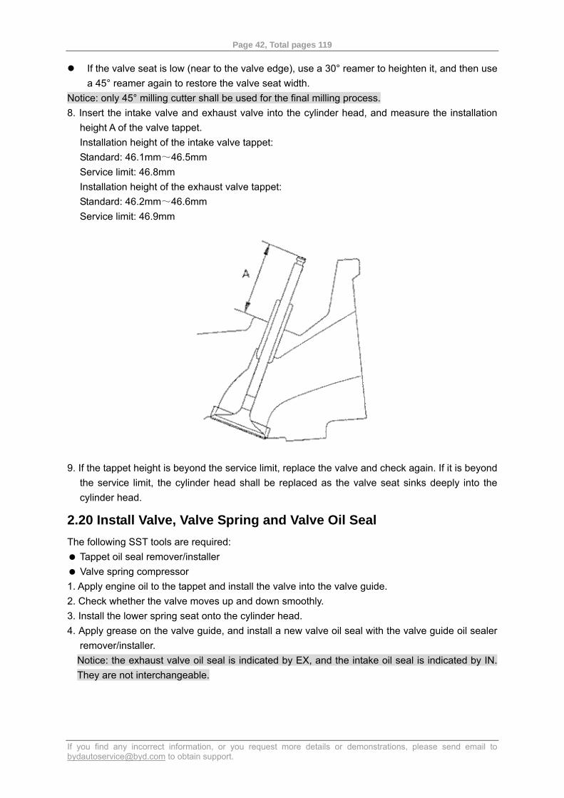
Notice: only 45° milling cutter shall be used for the final milling process. 8. Insert the intake valve and exhaust valve into the cylinder head, and measure the installation
height A of the valve tappet. Installation height of the intake valve tappet: Standard: 46.1mm~46.5mm Service limit: 46.8mm Installation height of the exhaust valve tappet: Standard: 46.2mm~46.6mm Service limit: 46.9mm
9. If the tappet height is beyond the service limit, replace the valve and check again. If it is beyond the service limit, the cylinder head shall be replaced as the valve seat sinks deeply into the cylinder head.
2.20 Install Valve, Valve Spring and Valve Oil Seal The following SST tools are required:
Tappet oil seal remover/installer Valve spring compressor
1. Apply engine oil to the tappet and install the valve into the valve guide. 2. Check whether the valve moves up and down smoothly. 3. Install the lower spring seat onto the cylinder head. 4. Apply grease on the valve guide, and install a new valve oil seal with the valve guide oil sealer
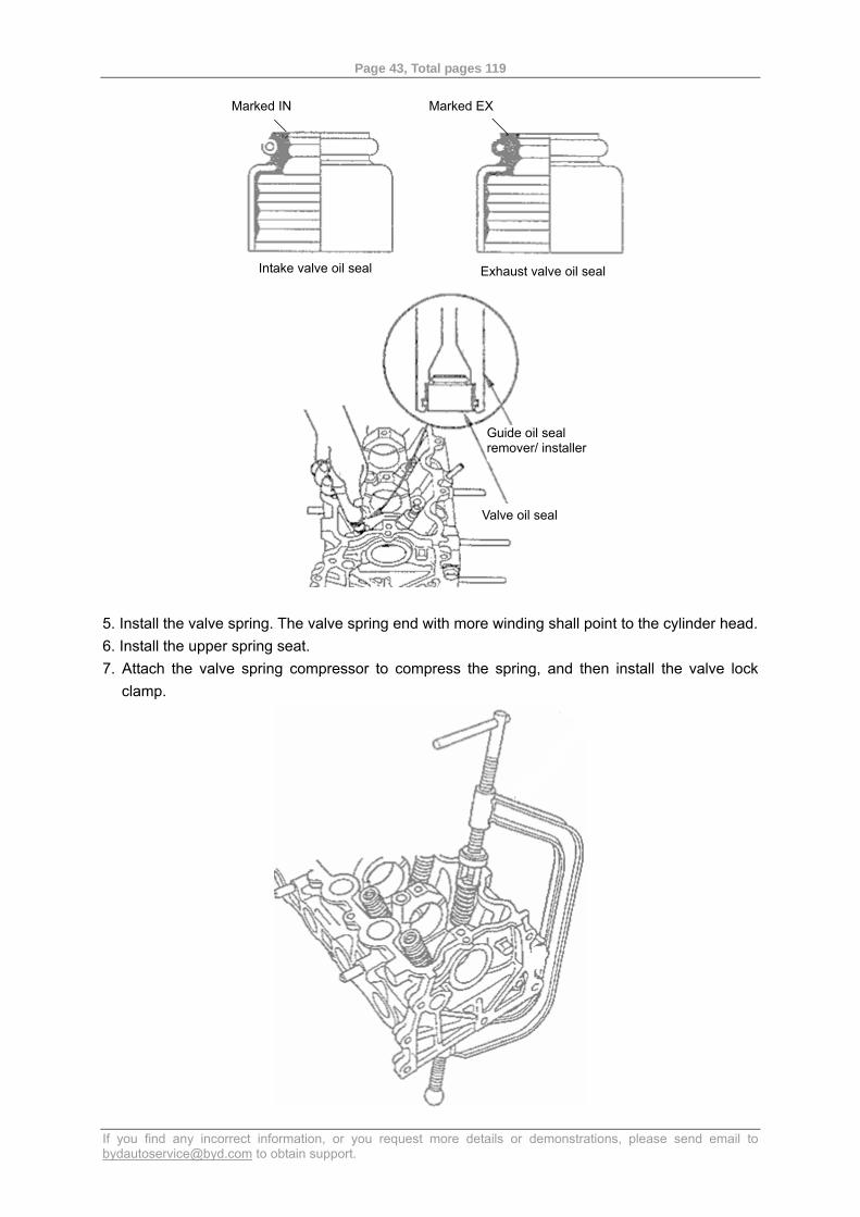
remover/installer. Notice: the exhaust valve oil seal is indicated by EX, and the intake oil seal is indicated by IN. They are not interchangeable.
Page 43, Total pages 119
If you find any incorrect information, or you request more details or demonstrations, please send email to [email protected] to obtain support.
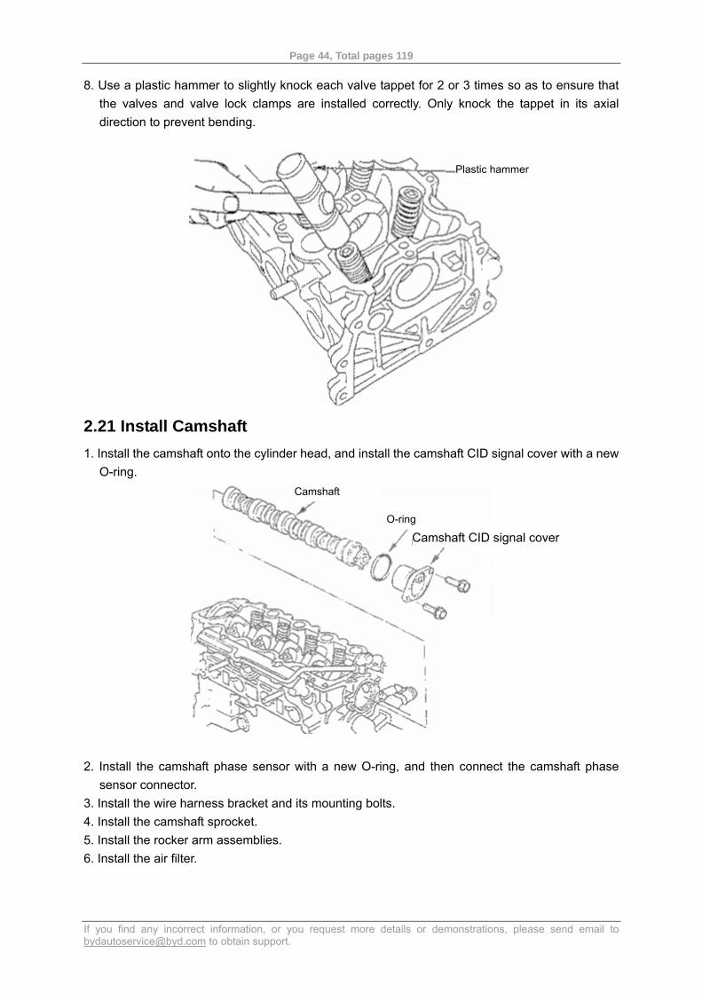
5. Install the valve spring. The valve spring end with more winding shall point to the cylinder head. 6. Install the upper spring seat. 7. Attach the valve spring compressor to compress the spring, and then install the valve lock
clamp.
Marked IN Marked EX
Intake valve oil seal Exhaust valve oil seal
Guide oil seal remover/ installer
Valve oil seal
Page 44, Total pages 119
If you find any incorrect information, or you request more details or demonstrations, please send email to [email protected] to obtain support.
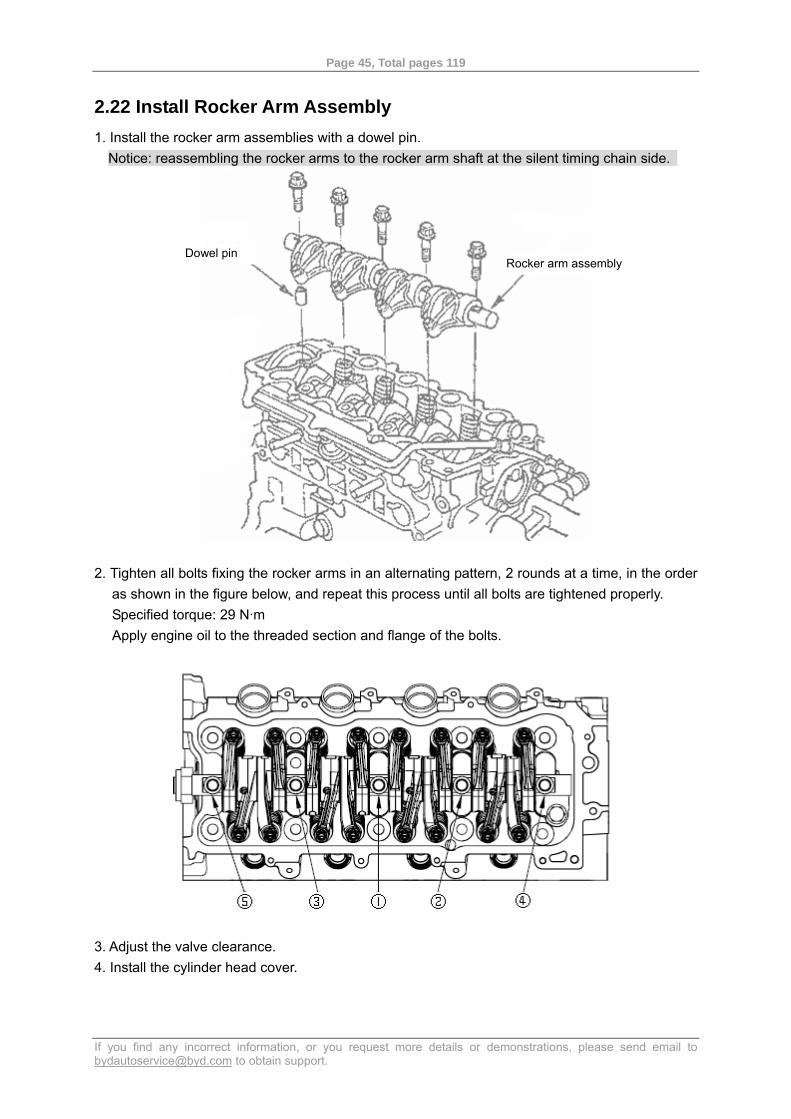
8. Use a plastic hammer to slightly knock each valve tappet for 2 or 3 times so as to ensure that the valves and valve lock clamps are installed correctly. Only knock the tappet in its axial direction to prevent bending.
2.21 Install Camshaft 1. Install the camshaft onto the cylinder head, and install the camshaft CID signal cover with a new
O-ring.
2. Install the camshaft phase sensor with a new O-ring, and then connect the camshaft phase
sensor connector. 3. Install the wire harness bracket and its mounting bolts. 4. Install the camshaft sprocket. 5. Install the rocker arm assemblies. 6. Install the air filter.
Plastic hammer
Camshaft
O-ring
Camshaft CID signal cover
Page 45, Total pages 119
If you find any incorrect information, or you request more details or demonstrations, please send email to [email protected] to obtain support.
2.22 Install Rocker Arm Assembly 1. Install the rocker arm assemblies with a dowel pin.
Notice: reassembling the rocker arms to the rocker arm shaft at the silent timing chain side.
2. Tighten all bolts fixing the rocker arms in an alternating pattern, 2 rounds at a time, in the order
as shown in the figure below, and repeat this process until all bolts are tightened properly. Specified torque: 29 N·m Apply engine oil to the threaded section and flange of the bolts.
3. Adjust the valve clearance. 4. Install the cylinder head cover.
Rocker arm assembly Dowel pin
Page 46, Total pages 119
If you find any incorrect information, or you request more details or demonstrations, please send email to [email protected] to obtain support.
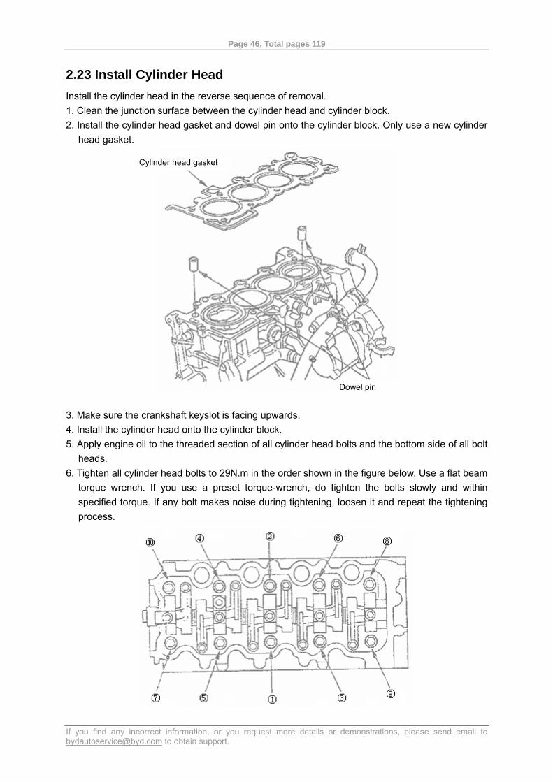
2.23 Install Cylinder Head Install the cylinder head in the reverse sequence of removal. 1. Clean the junction surface between the cylinder head and cylinder block. 2. Install the cylinder head gasket and dowel pin onto the cylinder block. Only use a new cylinder
head gasket.
3. Make sure the crankshaft keyslot is facing upwards. 4. Install the cylinder head onto the cylinder block. 5. Apply engine oil to the threaded section of all cylinder head bolts and the bottom side of all bolt
heads. 6. Tighten all cylinder head bolts to 29N.m in the order shown in the figure below. Use a flat beam
torque wrench. If you use a preset torque-wrench, do tighten the bolts slowly and within specified torque. If any bolt makes noise during tightening, loosen it and repeat the tightening process.
Cylinder head gasket
Dowel pin
Page 47, Total pages 119
If you find any incorrect information, or you request more details or demonstrations, please send email to [email protected] to obtain support.
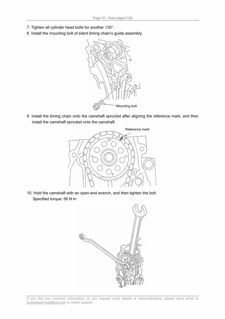
7. Tighten all cylinder head bolts for another 130°. 8. Install the mounting bolt of silent timing chain’s guide assembly.
9. Install the timing chain onto the camshaft sprocket after aligning the reference mark, and then
install the camshaft sprocket onto the camshaft.
10. Hold the camshaft with an open-end wrench, and then tighten the bolt. Specified torque: 56 N·m
Mounting bolt
Reference mark
Page 48, Total pages 119
If you find any incorrect information, or you request more details or demonstrations, please send email to [email protected] to obtain support.
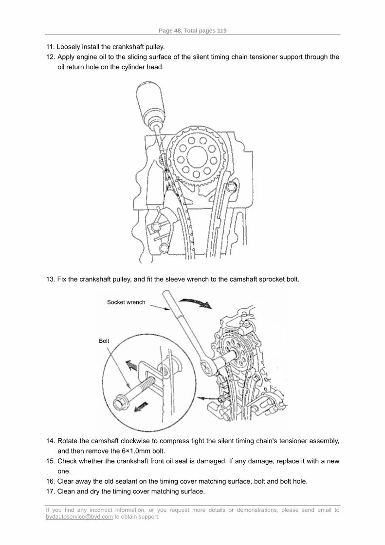
11. Loosely install the crankshaft pulley. 12. Apply engine oil to the sliding surface of the silent timing chain tensioner support through the
oil return hole on the cylinder head.
13. Fix the crankshaft pulley, and fit the sleeve wrench to the camshaft sprocket bolt.
14. Rotate the camshaft clockwise to compress tight the silent timing chain's tensioner assembly,
and then remove the 6×1.0mm bolt. 15. Check whether the crankshaft front oil seal is damaged. If any damage, replace it with a new
one. 16. Clear away the old sealant on the timing cover matching surface, bolt and bolt hole. 17. Clean and dry the timing cover matching surface.
Socket wrench
Bolt
Page 49, Total pages 119
If you find any incorrect information, or you request more details or demonstrations, please send email to [email protected] to obtain support.
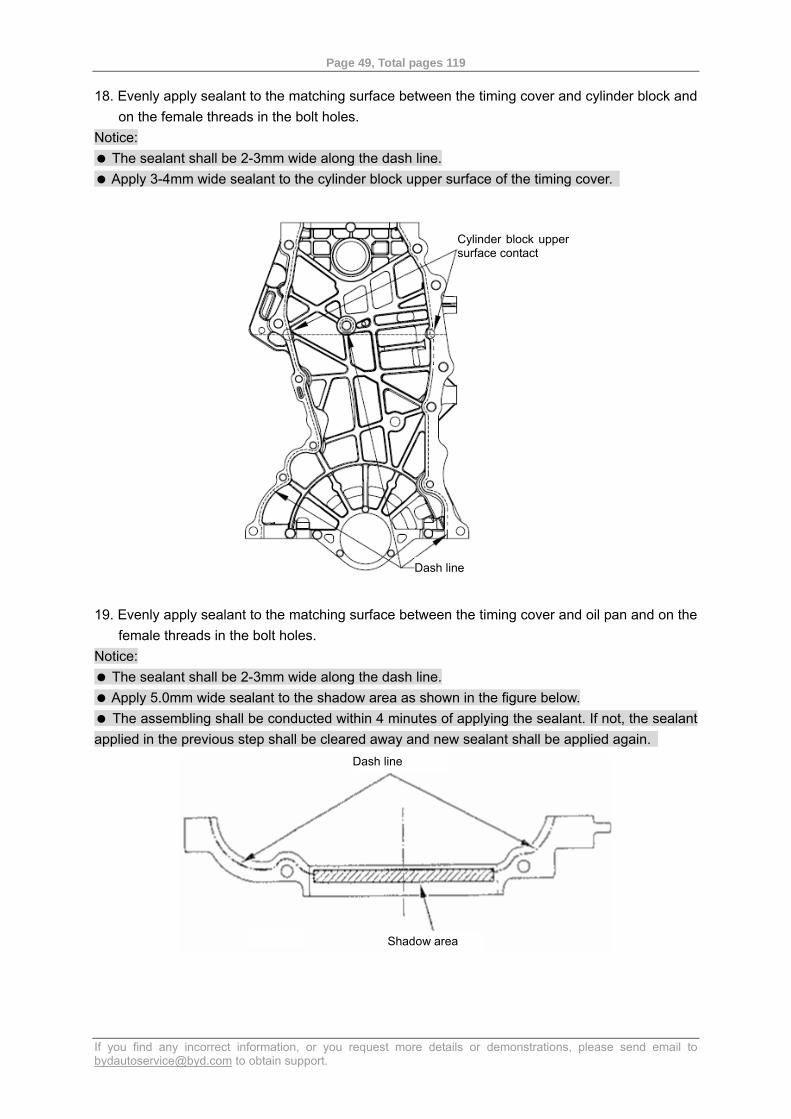
18. Evenly apply sealant to the matching surface between the timing cover and cylinder block and on the female threads in the bolt holes.
Notice: The sealant shall be 2-3mm wide along the dash line. Apply 3-4mm wide sealant to the cylinder block upper surface of the timing cover.
19. Evenly apply sealant to the matching surface between the timing cover and oil pan and on the female threads in the bolt holes.
Notice: The sealant shall be 2-3mm wide along the dash line. Apply 5.0mm wide sealant to the shadow area as shown in the figure below. The assembling shall be conducted within 4 minutes of applying the sealant. If not, the sealant
applied in the previous step shall be cleared away and new sealant shall be applied again.
Cylinder block upper surface contact
Dash line
Dash line
Shadow area
Page 50, Total pages 119
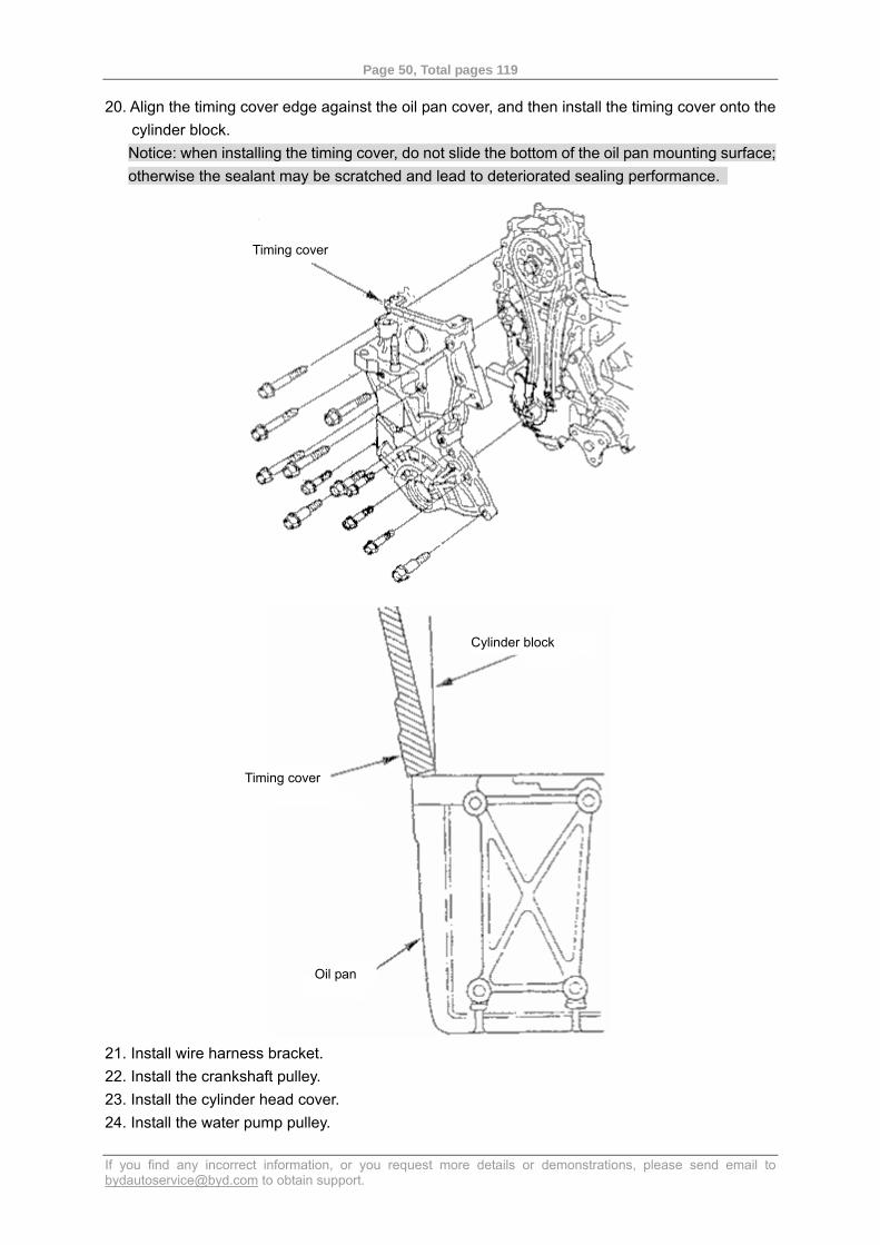
If you find any incorrect information, or you request more details or demonstrations, please send email to [email protected] to obtain support.
20. Align the timing cover edge against the oil pan cover, and then install the timing cover onto the cylinder block. Notice: when installing the timing cover, do not slide the bottom of the oil pan mounting surface; otherwise the sealant may be scratched and lead to deteriorated sealing performance.
21. Install wire harness bracket. 22. Install the crankshaft pulley. 23. Install the cylinder head cover. 24. Install the water pump pulley.
Timing cover
Cylinder block
Timing cover
Oil pan
Page 51, Total pages 119
If you find any incorrect information, or you request more details or demonstrations, please send email to [email protected] to obtain support.
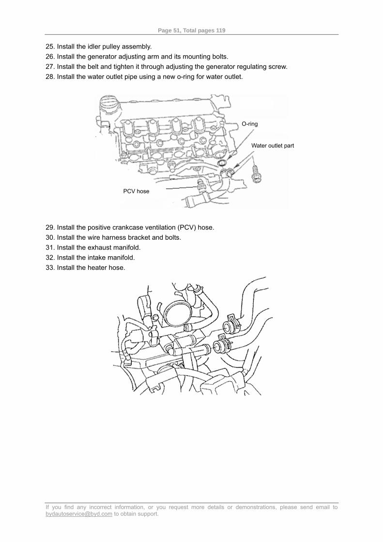
25. Install the idler pulley assembly. 26. Install the generator adjusting arm and its mounting bolts. 27. Install the belt and tighten it through adjusting the generator regulating screw. 28. Install the water outlet pipe using a new o-ring for water outlet.
29. Install the positive crankcase ventilation (PCV) hose. 30. Install the wire harness bracket and bolts. 31. Install the exhaust manifold. 32. Install the intake manifold. 33. Install the heater hose.
O-ring
Water outlet part
PCV hose
Page 52, Total pages 119
If you find any incorrect information, or you request more details or demonstrations, please send email to [email protected] to obtain support.
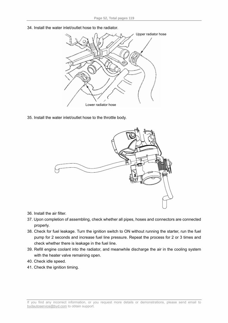
34. Install the water inlet/outlet hose to the radiator.
35. Install the water inlet/outlet hose to the throttle body.
36. Install the air filter. 37. Upon completion of assembling, check whether all pipes, hoses and connectors are connected
properly. 38. Check for fuel leakage. Turn the ignition switch to ON without running the starter, run the fuel
pump for 2 seconds and increase fuel line pressure. Repeat the process for 2 or 3 times and check whether there is leakage in the fuel line.
39. Refill engine coolant into the radiator, and meanwhile discharge the air in the cooling system with the heater valve remaining open.
40. Check idle speed. 41. Check the ignition timing.
Upper radiator hose
Lower radiator hose
Page 53, Total pages 119
If you find any incorrect information, or you request more details or demonstrations, please send email to [email protected] to obtain support.
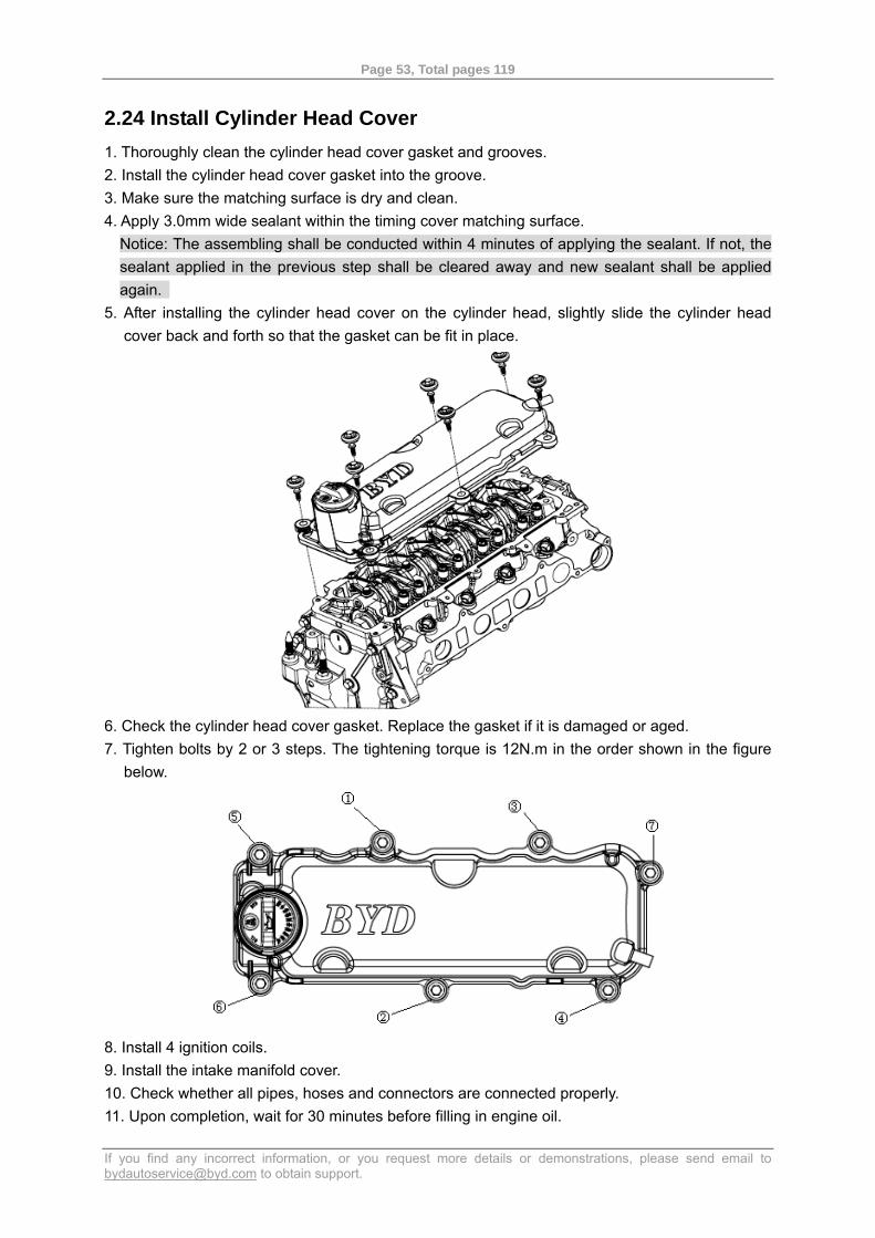
2.24 Install Cylinder Head Cover 1. Thoroughly clean the cylinder head cover gasket and grooves. 2. Install the cylinder head cover gasket into the groove. 3. Make sure the matching surface is dry and clean. 4. Apply 3.0mm wide sealant within the timing cover matching surface.
Notice: The assembling shall be conducted within 4 minutes of applying the sealant. If not, the sealant applied in the previous step shall be cleared away and new sealant shall be applied again.
5. After installing the cylinder head cover on the cylinder head, slightly slide the cylinder head cover back and forth so that the gasket can be fit in place.
6. Check the cylinder head cover gasket. Replace the gasket if it is damaged or aged. 7. Tighten bolts by 2 or 3 steps. The tightening torque is 12N.m in the order shown in the figure
below.
8. Install 4 ignition coils. 9. Install the intake manifold cover. 10. Check whether all pipes, hoses and connectors are connected properly. 11. Upon completion, wait for 30 minutes before filling in engine oil.

Page 54, Total pages 119
If you find any incorrect information, or you request more details or demonstrations, please send email to [email protected] to obtain support.
Section 3 Cylinder Block Component Layout (a)
Main bearing cap
Main bearing cap axle
Crankshaft
Main bearing bush
Thrust plate
Crankshaft oil seal
Flywheel
Flywheel bolt
Page 55, Total pages 119
If you find any incorrect information, or you request more details or demonstrations, please send email to [email protected] to obtain support.
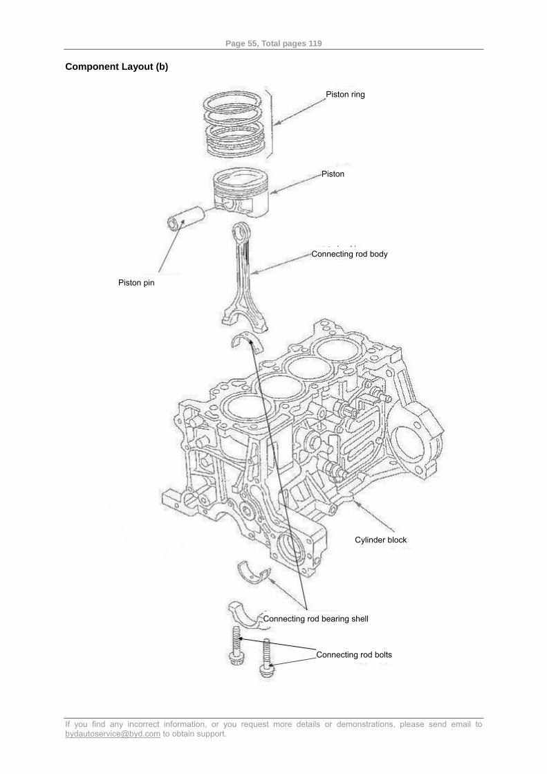
Component Layout (b)
Piston ring
Piston
Connecting rod body
Piston pin
Cylinder block
Connecting rod bolts
Connecting rod bearing shell
Page 56, Total pages 119
If you find any incorrect information, or you request more details or demonstrations, please send email to [email protected] to obtain support.
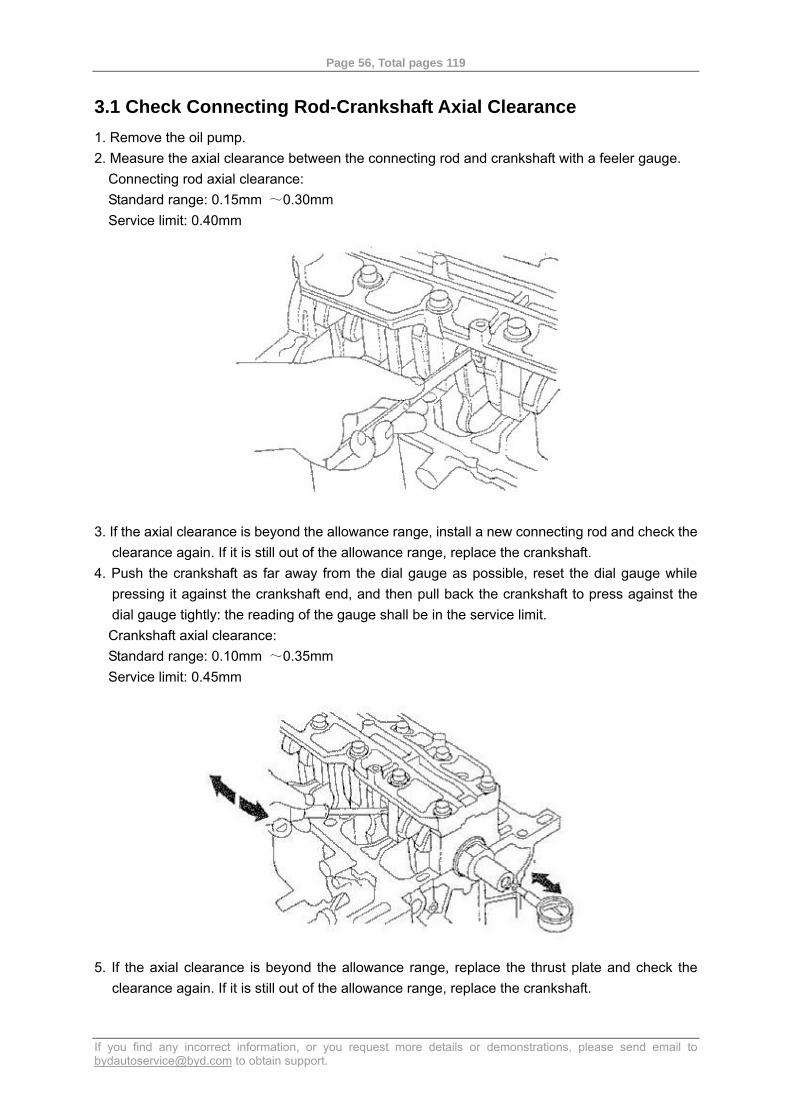
3.1 Check Connecting Rod-Crankshaft Axial Clearance 1. Remove the oil pump. 2. Measure the axial clearance between the connecting rod and crankshaft with a feeler gauge.
Connecting rod axial clearance: Standard range: 0.15mm ~0.30mm Service limit: 0.40mm
3. If the axial clearance is beyond the allowance range, install a new connecting rod and check the
clearance again. If it is still out of the allowance range, replace the crankshaft. 4. Push the crankshaft as far away from the dial gauge as possible, reset the dial gauge while
pressing it against the crankshaft end, and then pull back the crankshaft to press against the dial gauge tightly: the reading of the gauge shall be in the service limit. Crankshaft axial clearance: Standard range: 0.10mm ~0.35mm Service limit: 0.45mm
5. If the axial clearance is beyond the allowance range, replace the thrust plate and check the
clearance again. If it is still out of the allowance range, replace the crankshaft.
Page 57, Total pages 119
If you find any incorrect information, or you request more details or demonstrations, please send email to [email protected] to obtain support.
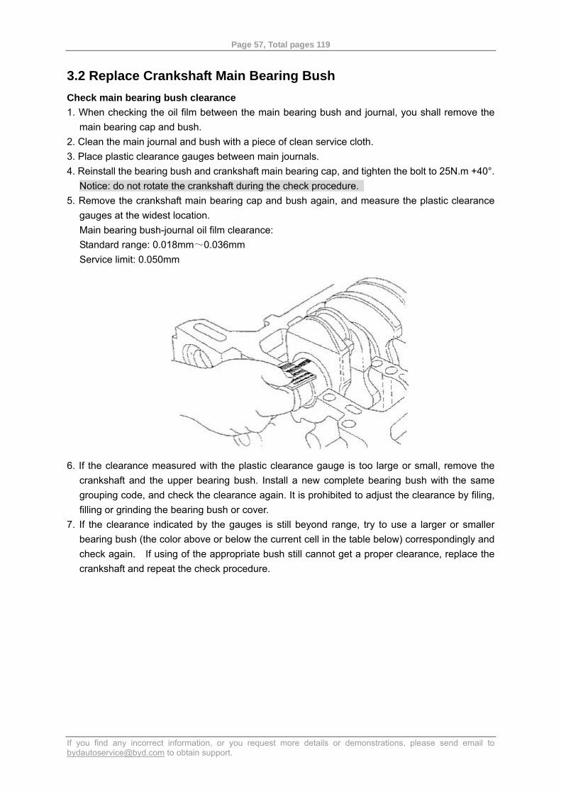
3.2 Replace Crankshaft Main Bearing Bush Check main bearing bush clearance 1. When checking the oil film between the main bearing bush and journal, you shall remove the
main bearing cap and bush. 2. Clean the main journal and bush with a piece of clean service cloth. 3. Place plastic clearance gauges between main journals. 4. Reinstall the bearing bush and crankshaft main bearing cap, and tighten the bolt to 25N.m +40°.
Notice: do not rotate the crankshaft during the check procedure. 5. Remove the crankshaft main bearing cap and bush again, and measure the plastic clearance
gauges at the widest location. Main bearing bush-journal oil film clearance: Standard range: 0.018mm~0.036mm Service limit: 0.050mm
6. If the clearance measured with the plastic clearance gauge is too large or small, remove the crankshaft and the upper bearing bush. Install a new complete bearing bush with the same grouping code, and check the clearance again. It is prohibited to adjust the clearance by filing, filling or grinding the bearing bush or cover.
7. If the clearance indicated by the gauges is still beyond range, try to use a larger or smaller bearing bush (the color above or below the current cell in the table below) correspondingly and check again. If using of the appropriate bush still cannot get a proper clearance, replace the crankshaft and repeat the check procedure.
Page 58, Total pages 119
If you find any incorrect information, or you request more details or demonstrations, please send email to [email protected] to obtain support.
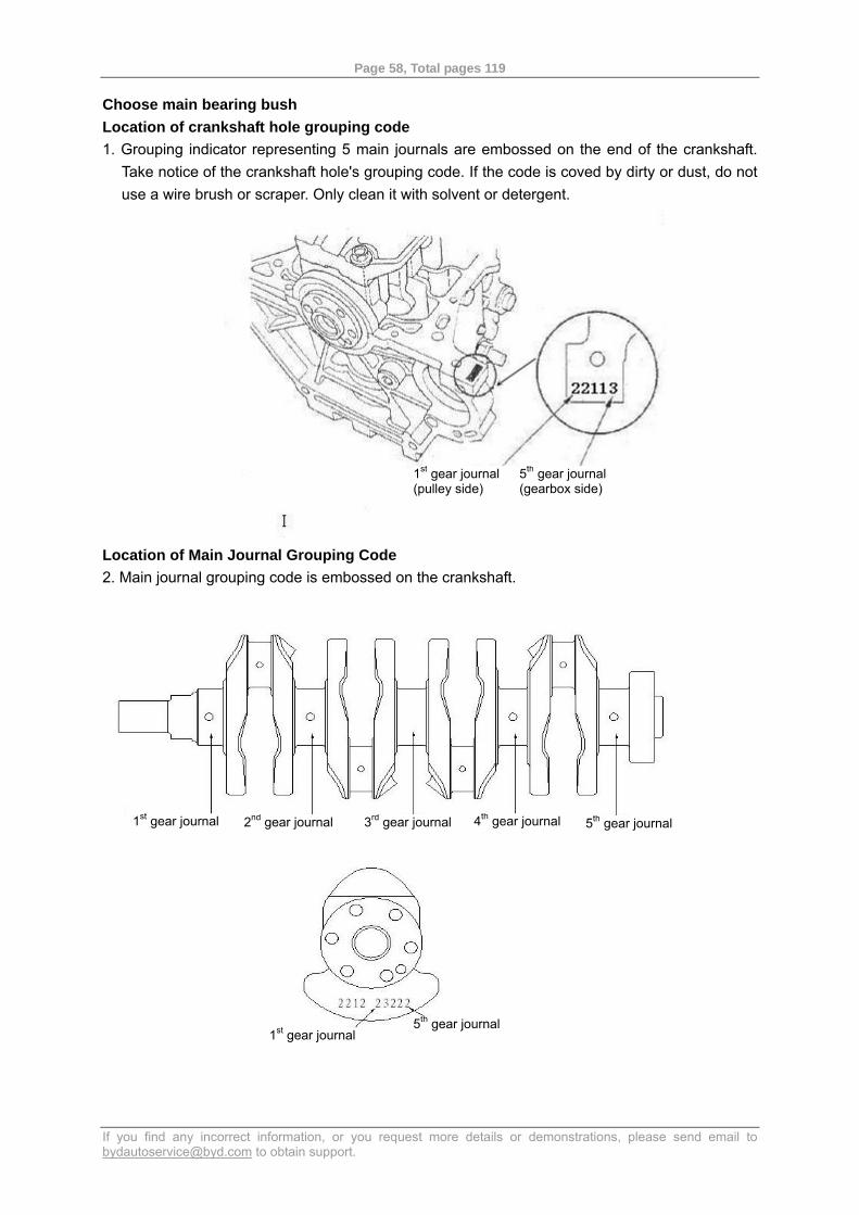
Choose main bearing bush Location of crankshaft hole grouping code 1. Grouping indicator representing 5 main journals are embossed on the end of the crankshaft.
Take notice of the crankshaft hole's grouping code. If the code is coved by dirty or dust, do not use a wire brush or scraper. Only clean it with solvent or detergent.
Location of Main Journal Grouping Code 2. Main journal grouping code is embossed on the crankshaft.
1st gear journal (pulley side)
5th gear journal (gearbox side)
1st gear journal 2nd gear journal 3rd gear journal 4th gear journal 5th gear journal
1st gear journal 5th gear journal
Page 59, Total pages 119
If you find any incorrect information, or you request more details or demonstrations, please send email to [email protected] to obtain support.
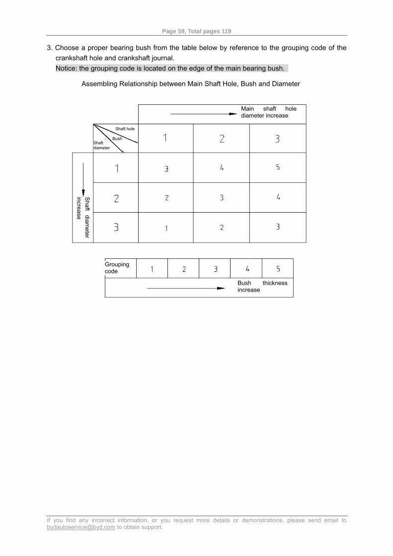
3. Choose a proper bearing bush from the table below by reference to the grouping code of the crankshaft hole and crankshaft journal. Notice: the grouping code is located on the edge of the main bearing bush.
Assembling Relationship between Main Shaft Hole, Bush and Diameter
Main shaft hole diameter increase
Shaft hole
Shaft diameter
Bush
Shaft
diameter
increase
Grouping code
Bush thickness increase

Page 60, Total pages 119
If you find any incorrect information, or you request more details or demonstrations, please send email to [email protected] to obtain support.
3.3 Replace Connecting Rod Bearing Shell Check connecting rod bearing clearance 1. Check the oil film clearance between the connecting rod bearing and journal. Remove the main
bearing cap. 2. Remove the connecting rod cover and connecting rod bearing shell. 3. Clean the crankshaft connecting rod journal and bearing shell with a piece of clean service
cloth. 4. Place a plastic clearance gauge on the connecting rod journal. 5. Reinstall the bearing shell and connecting rod cover and tighten the bolts.
Tightening torque: 9.8N.m+90° Notice: do not rotate the crankshaft during the check procedure.
6. Remove the connecting rod cover and bearing shell, and measure the plastic clearance gauge at the widest location. Connecting rod bearing shell-journal oil film clearance: Standard range: 0.020mm ~0.038mm Service limit: 0.050mm
7. If the clearance measured with the plastic clearance gauge is too large or small, remove the
upper bearing shell. Install a new complete bearing shell with the same grouping color code, and check the clearance again. It is prohibited to adjust the clearance by filing, filling or grinding the bearing or cover.
8. If the clearance indicated by the gauges is still beyond range, try to use a larger or smaller bearing bush (the color above or below the current cell in the table) correspondingly and check again. If using of the appropriate bearing shell still cannot get a proper clearance, replace the crankshaft and repeat the check procedure.
Page 61, Total pages 119
If you find any incorrect information, or you request more details or demonstrations, please send email to [email protected] to obtain support.
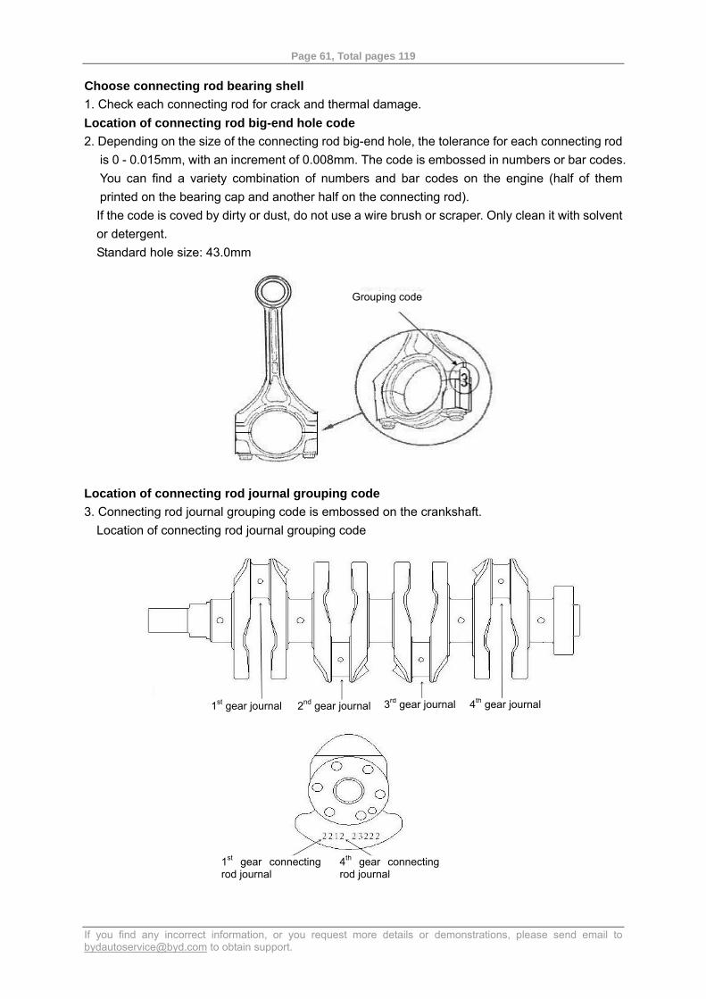
Choose connecting rod bearing shell 1. Check each connecting rod for crack and thermal damage. Location of connecting rod big-end hole code 2. Depending on the size of the connecting rod big-end hole, the tolerance for each connecting rod
is 0 - 0.015mm, with an increment of 0.008mm. The code is embossed in numbers or bar codes. You can find a variety combination of numbers and bar codes on the engine (half of them printed on the bearing cap and another half on the connecting rod). If the code is coved by dirty or dust, do not use a wire brush or scraper. Only clean it with solvent or detergent. Standard hole size: 43.0mm
Location of connecting rod journal grouping code 3. Connecting rod journal grouping code is embossed on the crankshaft.
Location of connecting rod journal grouping code
Grouping code
1st gear journal 2nd gear journal 3rd gear journal 4th gear journal
1st gear connectingrod journal
4th gear connecting rod journal
Page 62, Total pages 119
If you find any incorrect information, or you request more details or demonstrations, please send email to [email protected] to obtain support.
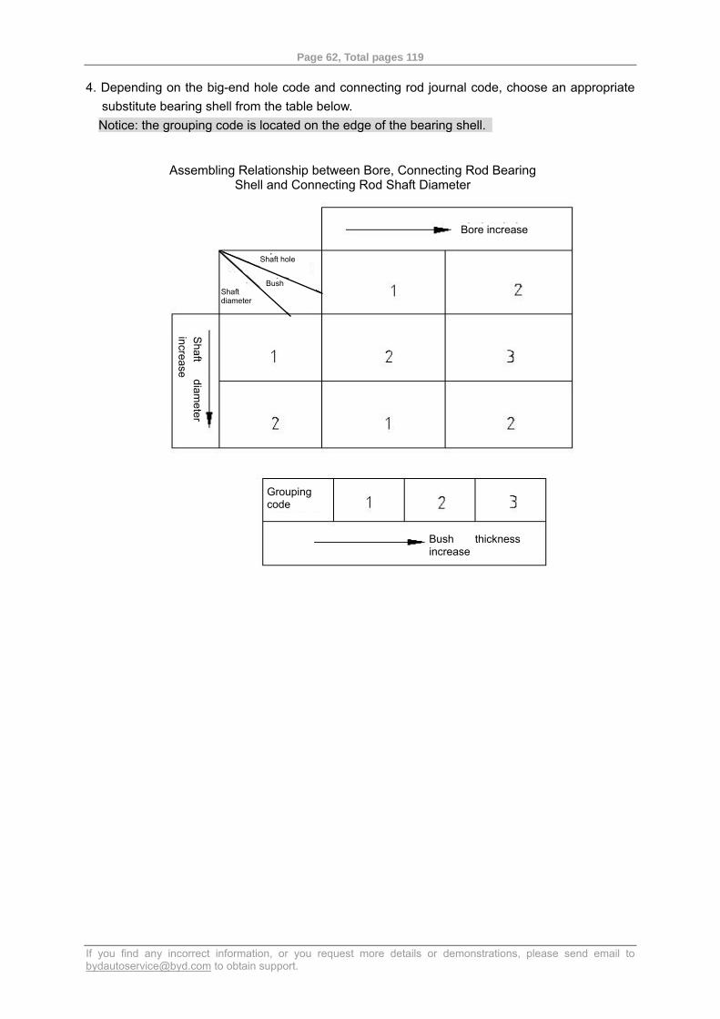
4. Depending on the big-end hole code and connecting rod journal code, choose an appropriate substitute bearing shell from the table below. Notice: the grouping code is located on the edge of the bearing shell.
Assembling Relationship between Bore, Connecting Rod Bearing Shell and Connecting Rod Shaft Diameter
Bore increase
Shaft
diameter
increase
Shaft hole
Shaft diameter
Bush
Bush thickness increase
Grouping code
Page 63, Total pages 119
If you find any incorrect information, or you request more details or demonstrations, please send email to [email protected] to obtain support.
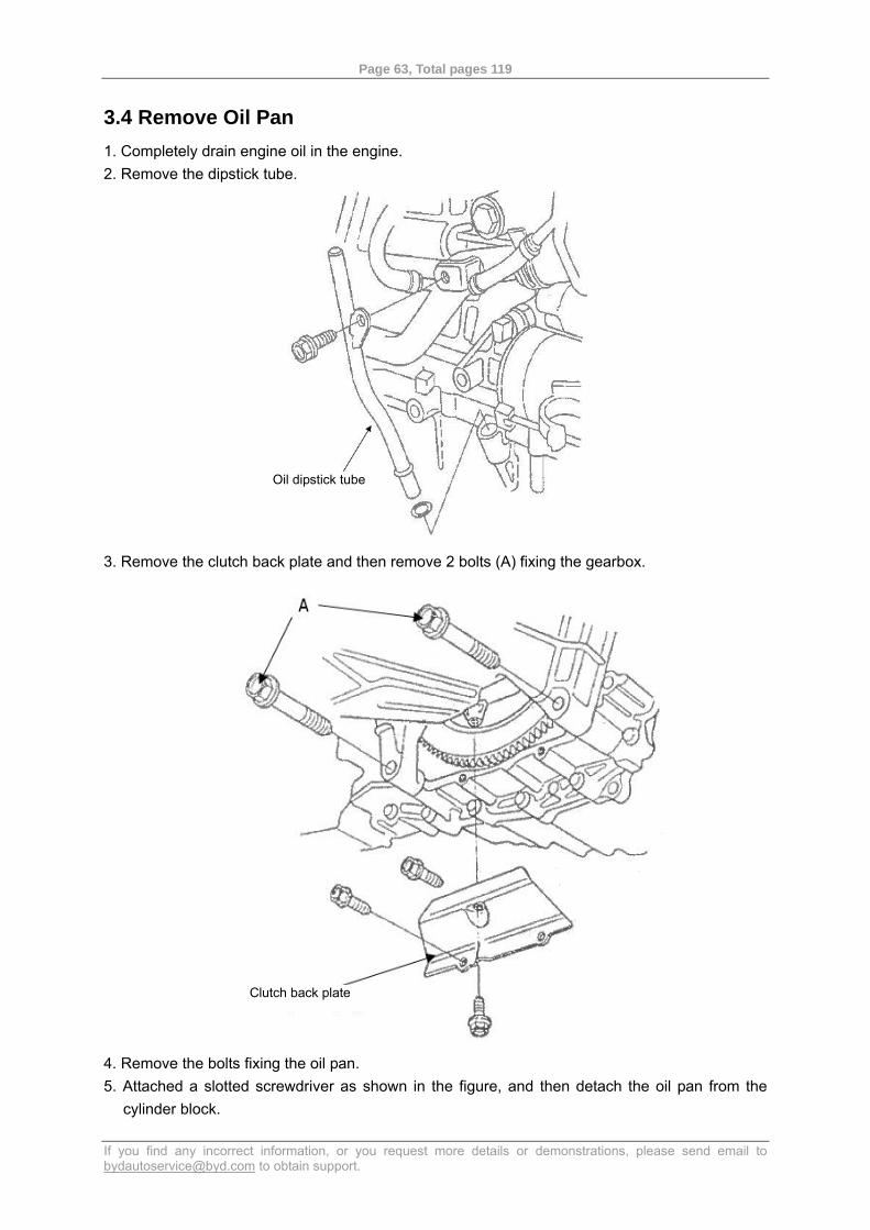
3.4 Remove Oil Pan 1. Completely drain engine oil in the engine. 2. Remove the dipstick tube.
3. Remove the clutch back plate and then remove 2 bolts (A) fixing the gearbox.
4. Remove the bolts fixing the oil pan. 5. Attached a slotted screwdriver as shown in the figure, and then detach the oil pan from the
cylinder block.
Oil dipstick tube
Clutch back plate
Page 64, Total pages 119
If you find any incorrect information, or you request more details or demonstrations, please send email to [email protected] to obtain support.
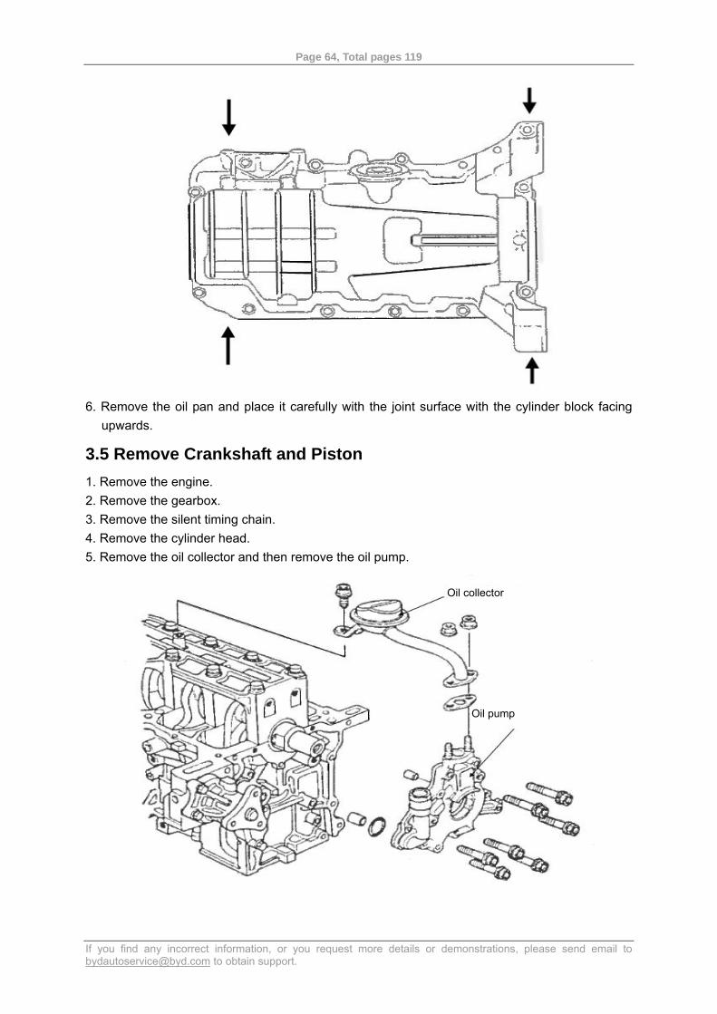
6. Remove the oil pan and place it carefully with the joint surface with the cylinder block facing
upwards.
3.5 Remove Crankshaft and Piston 1. Remove the engine. 2. Remove the gearbox. 3. Remove the silent timing chain. 4. Remove the cylinder head. 5. Remove the oil collector and then remove the oil pump.
Oil collector
Oil pump
Page 65, Total pages 119
If you find any incorrect information, or you request more details or demonstrations, please send email to [email protected] to obtain support.
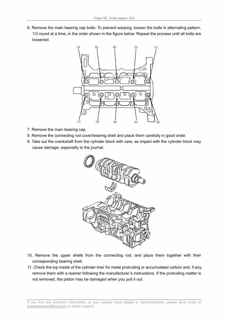
6. Remove the main bearing cap bolts. To prevent warping, loosen the bolts in alternating pattern, 1/3 round at a time, in the order shown in the figure below. Repeat the process until all bolts are loosened.
7. Remove the main bearing cap. 8. Remove the connecting rod cover/bearing shell and place them carefully in good order. 9. Take out the crankshaft from the cylinder block with care, as impact with the cylinder block may
cause damage, especially to the journal.
10. Remove the upper shells from the connecting rod, and place them together with their
corresponding bearing shell. 11. Check the top inside of the cylinder liner for metal protruding or accumulated carbon and, if any,
remove them with a reamer following the manufacturer’s instructions. If the protruding matter is not removed, the piston may be damaged when you pull it out.
Page 66, Total pages 119
If you find any incorrect information, or you request more details or demonstrations, please send email to [email protected] to obtain support.
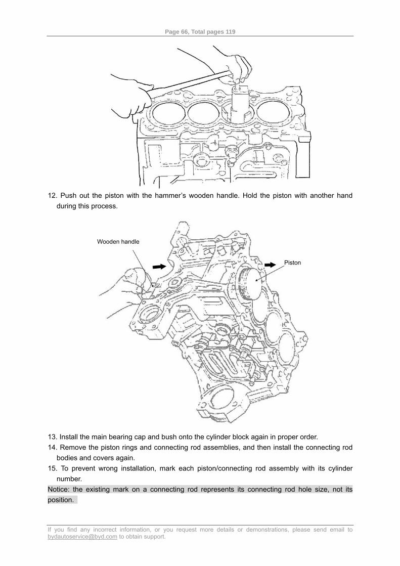
12. Push out the piston with the hammer’s wooden handle. Hold the piston with another hand
during this process.
13. Install the main bearing cap and bush onto the cylinder block again in proper order. 14. Remove the piston rings and connecting rod assemblies, and then install the connecting rod
bodies and covers again. 15. To prevent wrong installation, mark each piston/connecting rod assembly with its cylinder
number. Notice: the existing mark on a connecting rod represents its connecting rod hole size, not its position.
Piston
Wooden handle
Page 67, Total pages 119
If you find any incorrect information, or you request more details or demonstrations, please send email to [email protected] to obtain support.
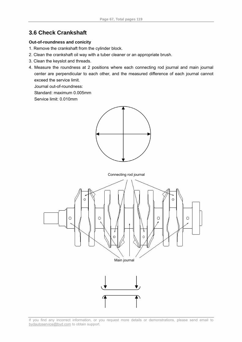
3.6 Check Crankshaft Out-of-roundness and conicity 1. Remove the crankshaft from the cylinder block. 2. Clean the crankshaft oil way with a tuber cleaner or an appropriate brush. 3. Clean the keyslot and threads. 4. Measure the roundness at 2 positions where each connecting rod journal and main journal
center are perpendicular to each other, and the measured difference of each journal cannot exceed the service limit. Journal out-of-roundness: Standard: maximum 0.005mm Service limit: 0.010mm
Connecting rod journal
Main journal
Page 68, Total pages 119
If you find any incorrect information, or you request more details or demonstrations, please send email to [email protected] to obtain support.
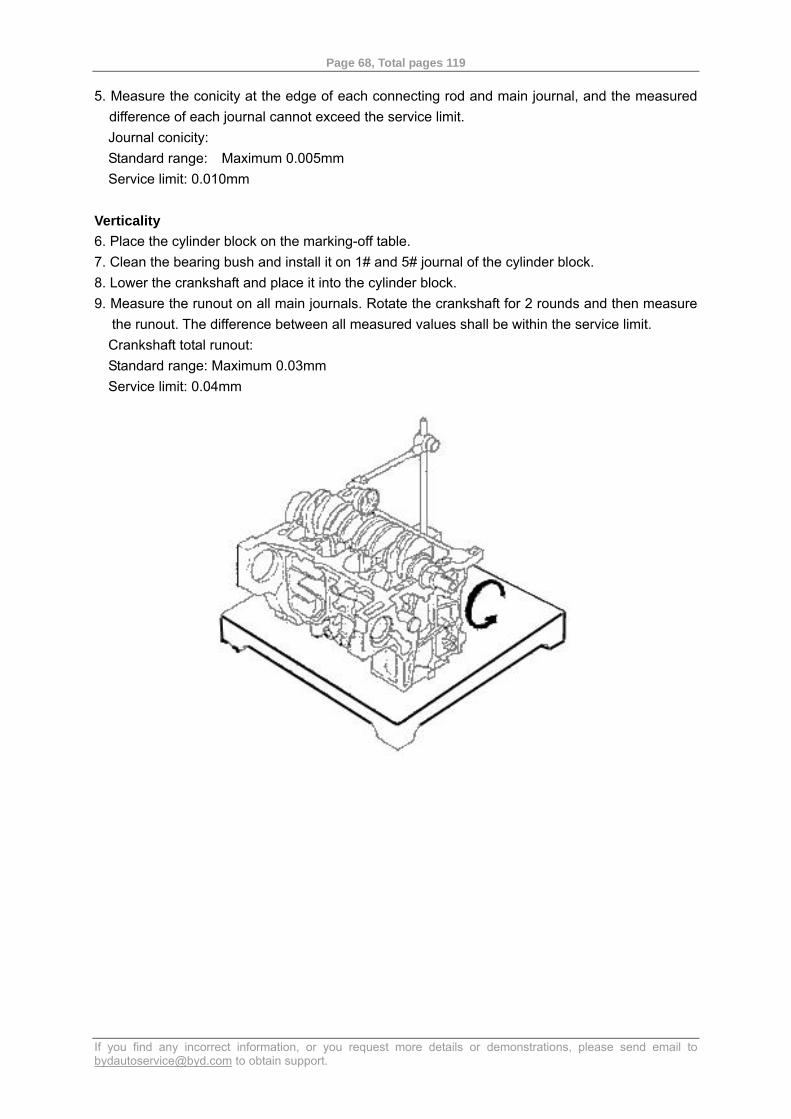
5. Measure the conicity at the edge of each connecting rod and main journal, and the measured difference of each journal cannot exceed the service limit. Journal conicity: Standard range: Maximum 0.005mm Service limit: 0.010mm
Verticality 6. Place the cylinder block on the marking-off table. 7. Clean the bearing bush and install it on 1# and 5# journal of the cylinder block. 8. Lower the crankshaft and place it into the cylinder block. 9. Measure the runout on all main journals. Rotate the crankshaft for 2 rounds and then measure
the runout. The difference between all measured values shall be within the service limit. Crankshaft total runout: Standard range: Maximum 0.03mm Service limit: 0.04mm
Page 69, Total pages 119
If you find any incorrect information, or you request more details or demonstrations, please send email to [email protected] to obtain support.
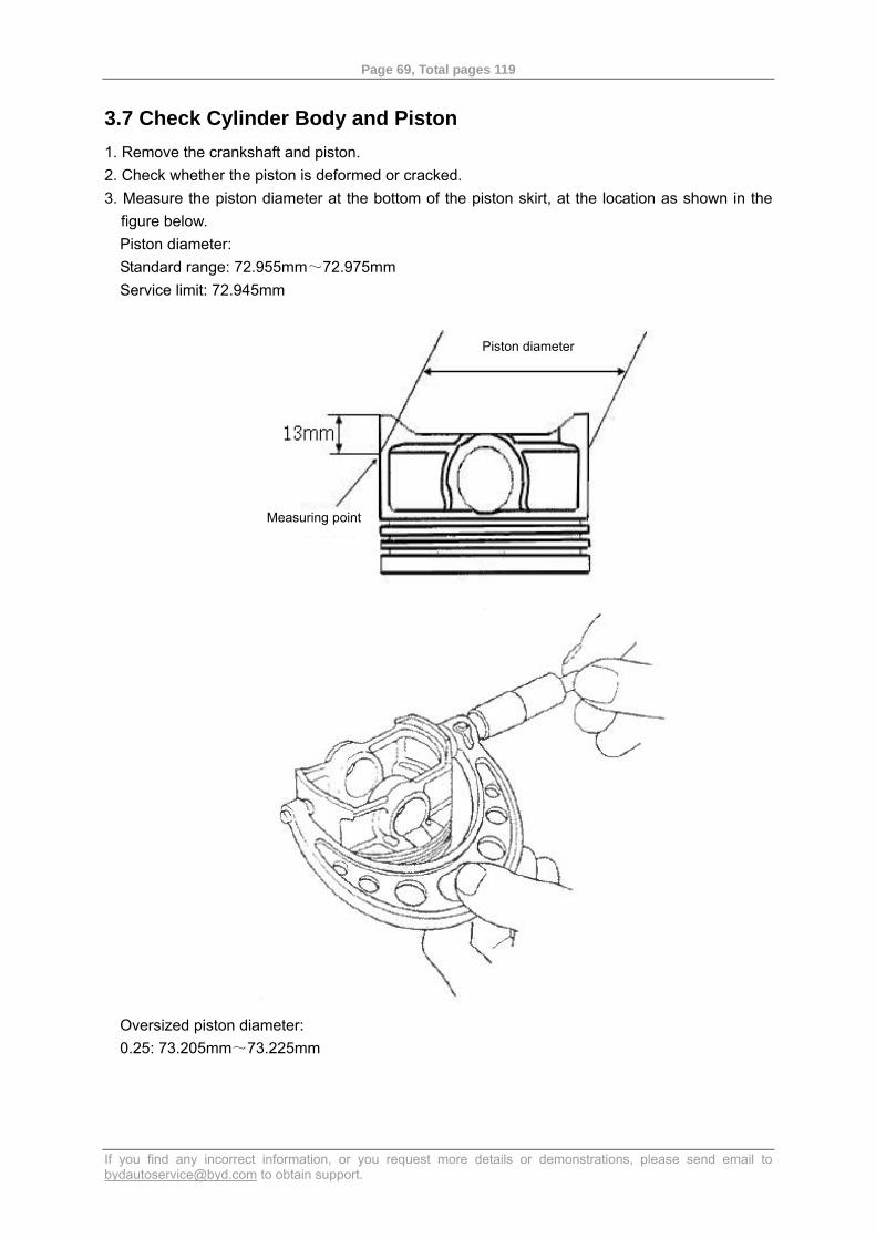
3.7 Check Cylinder Body and Piston 1. Remove the crankshaft and piston. 2. Check whether the piston is deformed or cracked. 3. Measure the piston diameter at the bottom of the piston skirt, at the location as shown in the
figure below. Piston diameter: Standard range: 72.955mm~72.975mm Service limit: 72.945mm
Oversized piston diameter: 0.25: 73.205mm~73.225mm
Piston diameter
Measuring point
Page 70, Total pages 119
If you find any incorrect information, or you request more details or demonstrations, please send email to [email protected] to obtain support.
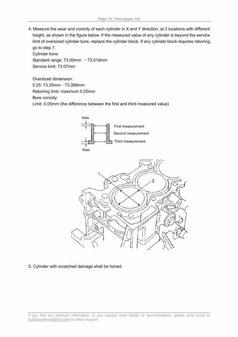
4. Measure the wear and conicity of each cylinder in X and Y direction, at 3 locations with different height, as shown in the figure below. If the measured value of any cylinder is beyond the service limit of oversized cylinder bore, replace the cylinder block. If any cylinder block requires reboring, go to step 7. Cylinder bore: Standard range: 73.00mm ~73.019mm Service limit: 73.07mm Oversized dimension: 0.25: 73.25mm~73.269mm Reboring limit: maximum 0.25mm Bore conicity: Limit: 0.05mm (the difference between the first and third measured value)
5. Cylinder with scratched damage shall be honed.
First measurement
Second measurement
Third measurement
Page 71, Total pages 119
If you find any incorrect information, or you request more details or demonstrations, please send email to [email protected] to obtain support.
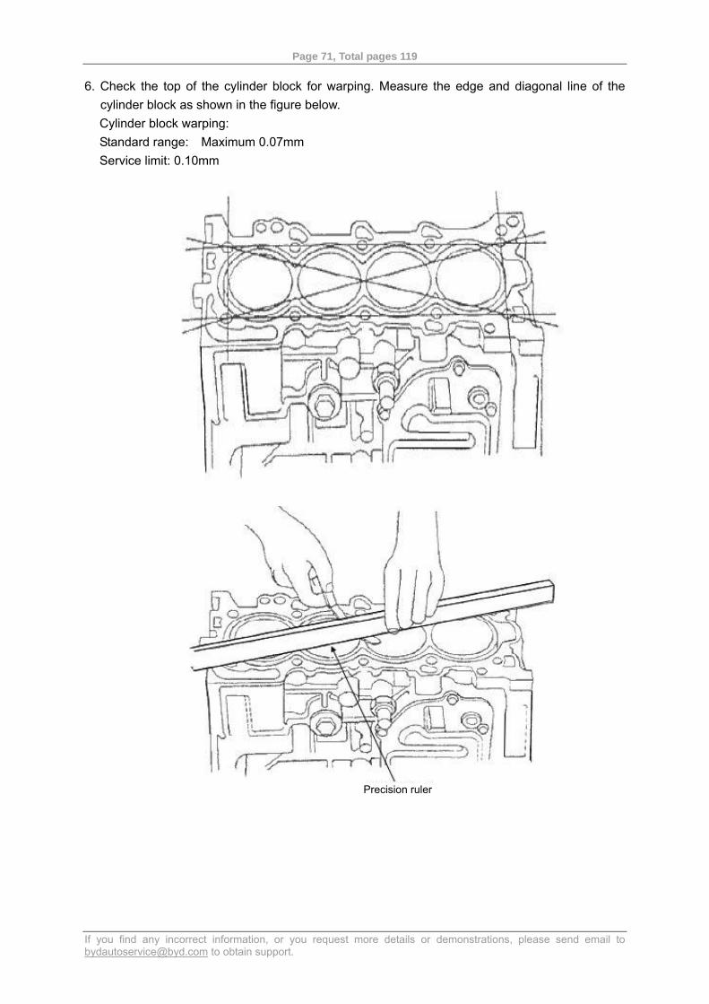
6. Check the top of the cylinder block for warping. Measure the edge and diagonal line of the cylinder block as shown in the figure below. Cylinder block warping: Standard range: Maximum 0.07mm Service limit: 0.10mm
Precision ruler
Page 72, Total pages 119
If you find any incorrect information, or you request more details or demonstrations, please send email to [email protected] to obtain support.
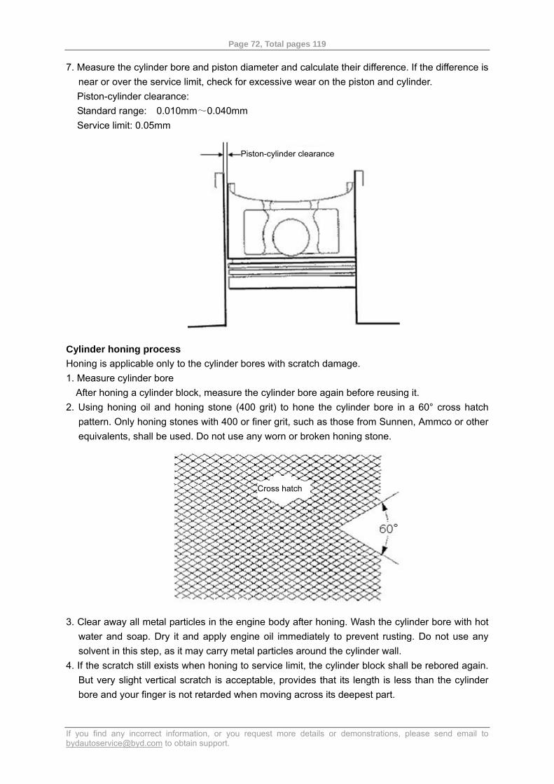
7. Measure the cylinder bore and piston diameter and calculate their difference. If the difference is near or over the service limit, check for excessive wear on the piston and cylinder. Piston-cylinder clearance: Standard range: 0.010mm~0.040mm Service limit: 0.05mm
Cylinder honing process Honing is applicable only to the cylinder bores with scratch damage. 1. Measure cylinder bore
After honing a cylinder block, measure the cylinder bore again before reusing it. 2. Using honing oil and honing stone (400 grit) to hone the cylinder bore in a 60° cross hatch
pattern. Only honing stones with 400 or finer grit, such as those from Sunnen, Ammco or other equivalents, shall be used. Do not use any worn or broken honing stone.
3. Clear away all metal particles in the engine body after honing. Wash the cylinder bore with hot
water and soap. Dry it and apply engine oil immediately to prevent rusting. Do not use any solvent in this step, as it may carry metal particles around the cylinder wall.
4. If the scratch still exists when honing to service limit, the cylinder block shall be rebored again. But very slight vertical scratch is acceptable, provides that its length is less than the cylinder bore and your finger is not retarded when moving across its deepest part.
Piston-cylinder clearance
Cross hatch
Page 73, Total pages 119
If you find any incorrect information, or you request more details or demonstrations, please send email to [email protected] to obtain support.
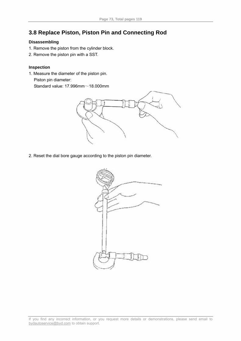
3.8 Replace Piston, Piston Pin and Connecting Rod Disassembling 1. Remove the piston from the cylinder block. 2. Remove the piston pin with a SST. Inspection 1. Measure the diameter of the piston pin.
Piston pin diameter: Standard value: 17.996mm~18.000mm
2. Reset the dial bore gauge according to the piston pin diameter.
Page 74, Total pages 119
If you find any incorrect information, or you request more details or demonstrations, please send email to [email protected] to obtain support.
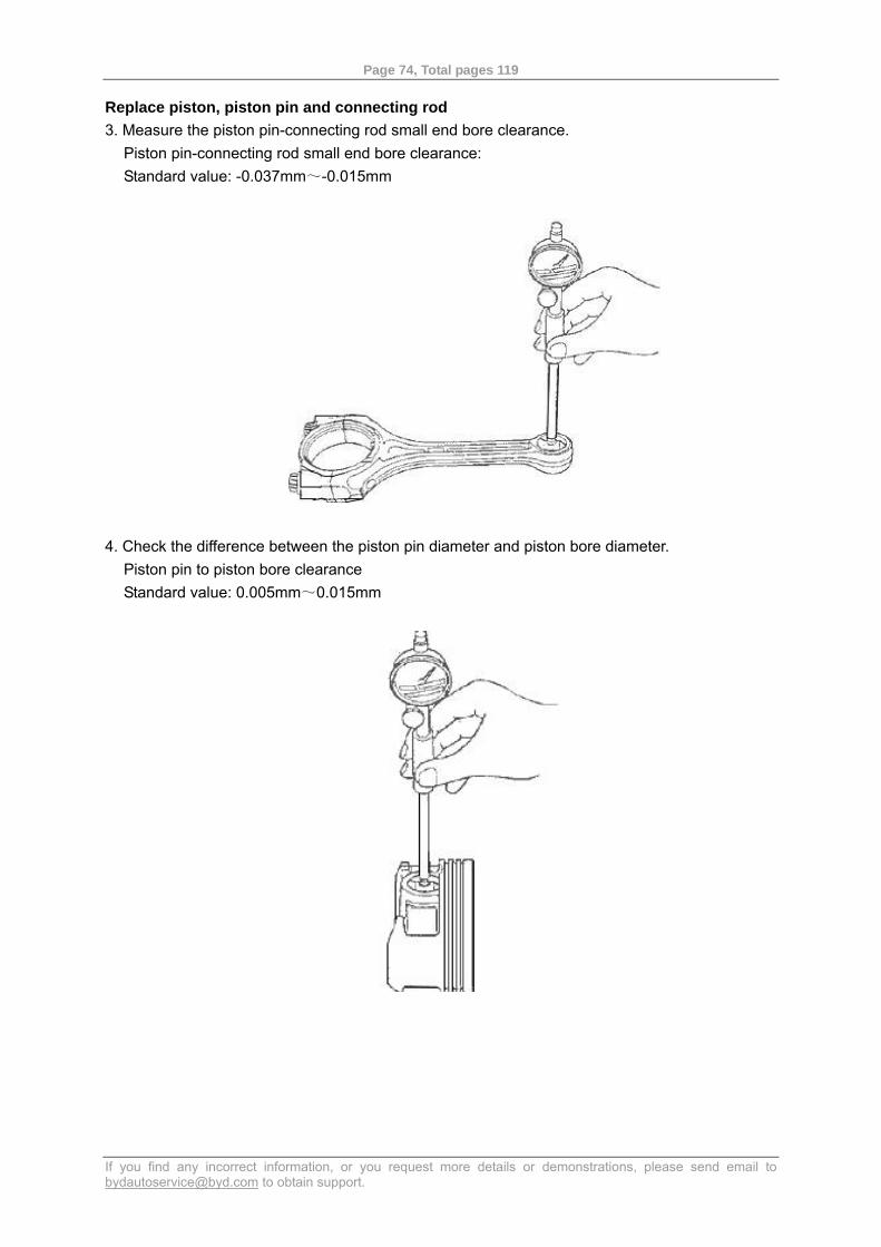
Replace piston, piston pin and connecting rod 3. Measure the piston pin-connecting rod small end bore clearance.
Piston pin-connecting rod small end bore clearance: Standard value: -0.037mm~-0.015mm
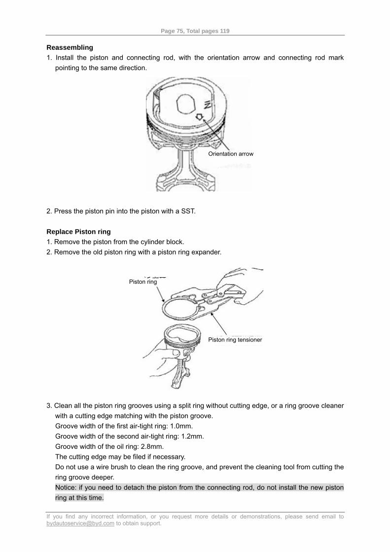
4. Check the difference between the piston pin diameter and piston bore diameter.
Piston pin to piston bore clearance Standard value: 0.005mm~0.015mm
Page 75, Total pages 119
If you find any incorrect information, or you request more details or demonstrations, please send email to [email protected] to obtain support.
Reassembling 1. Install the piston and connecting rod, with the orientation arrow and connecting rod mark
pointing to the same direction.
2. Press the piston pin into the piston with a SST. Replace Piston ring 1. Remove the piston from the cylinder block. 2. Remove the old piston ring with a piston ring expander.
3. Clean all the piston ring grooves using a split ring without cutting edge, or a ring groove cleaner with a cutting edge matching with the piston groove. Groove width of the first air-tight ring: 1.0mm. Groove width of the second air-tight ring: 1.2mm. Groove width of the oil ring: 2.8mm. The cutting edge may be filed if necessary. Do not use a wire brush to clean the ring groove, and prevent the cleaning tool from cutting the ring groove deeper. Notice: if you need to detach the piston from the connecting rod, do not install the new piston ring at this time.
Orientation arrow
Piston ring
Piston ring tensioner
Page 76, Total pages 119
If you find any incorrect information, or you request more details or demonstrations, please send email to [email protected] to obtain support.
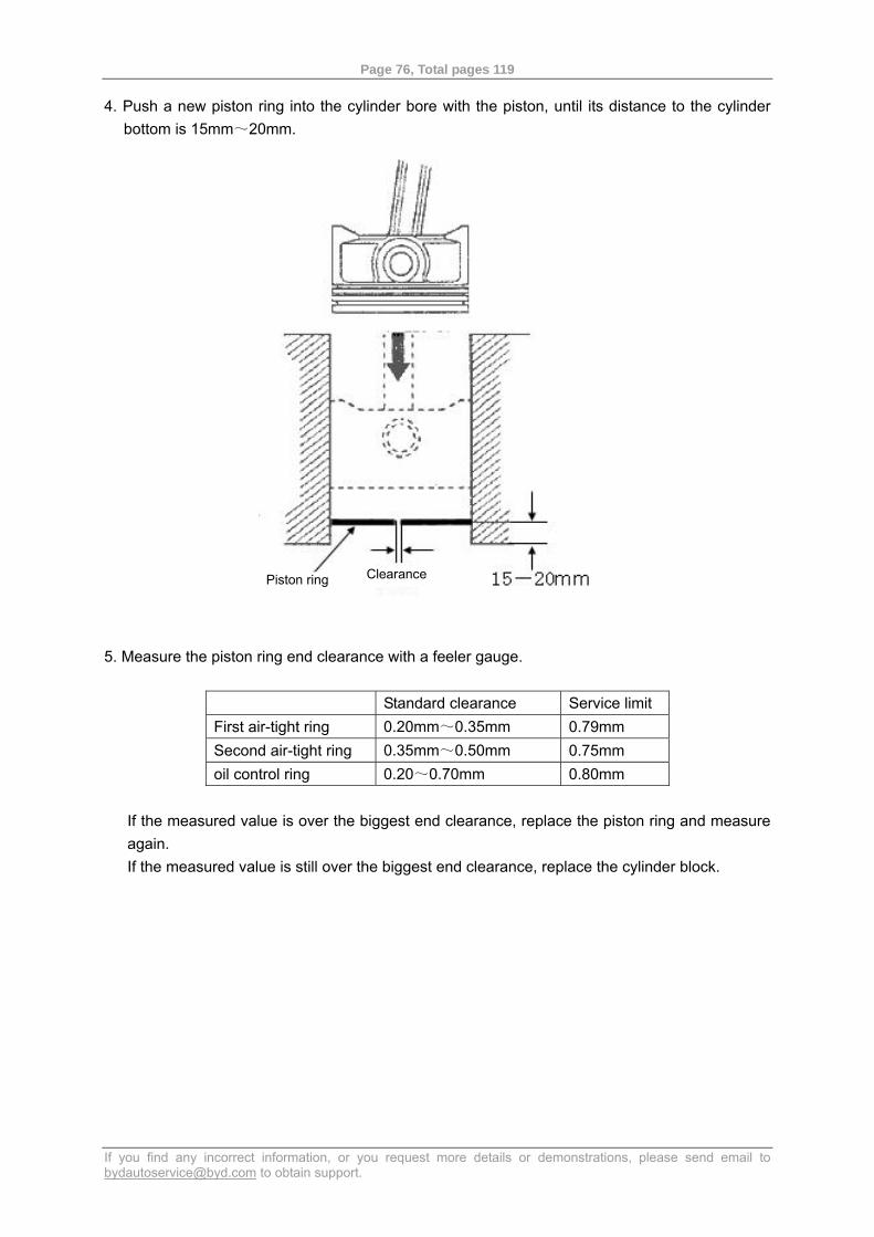
4. Push a new piston ring into the cylinder bore with the piston, until its distance to the cylinder bottom is 15mm~20mm.
5. Measure the piston ring end clearance with a feeler gauge.
Standard clearance Service limit First air-tight ring 0.20mm~0.35mm 0.79mm Second air-tight ring 0.35mm~0.50mm 0.75mm oil control ring 0.20~0.70mm 0.80mm
If the measured value is over the biggest end clearance, replace the piston ring and measure again. If the measured value is still over the biggest end clearance, replace the cylinder block.
Piston ring Clearance
Page 77, Total pages 119
If you find any incorrect information, or you request more details or demonstrations, please send email to [email protected] to obtain support.
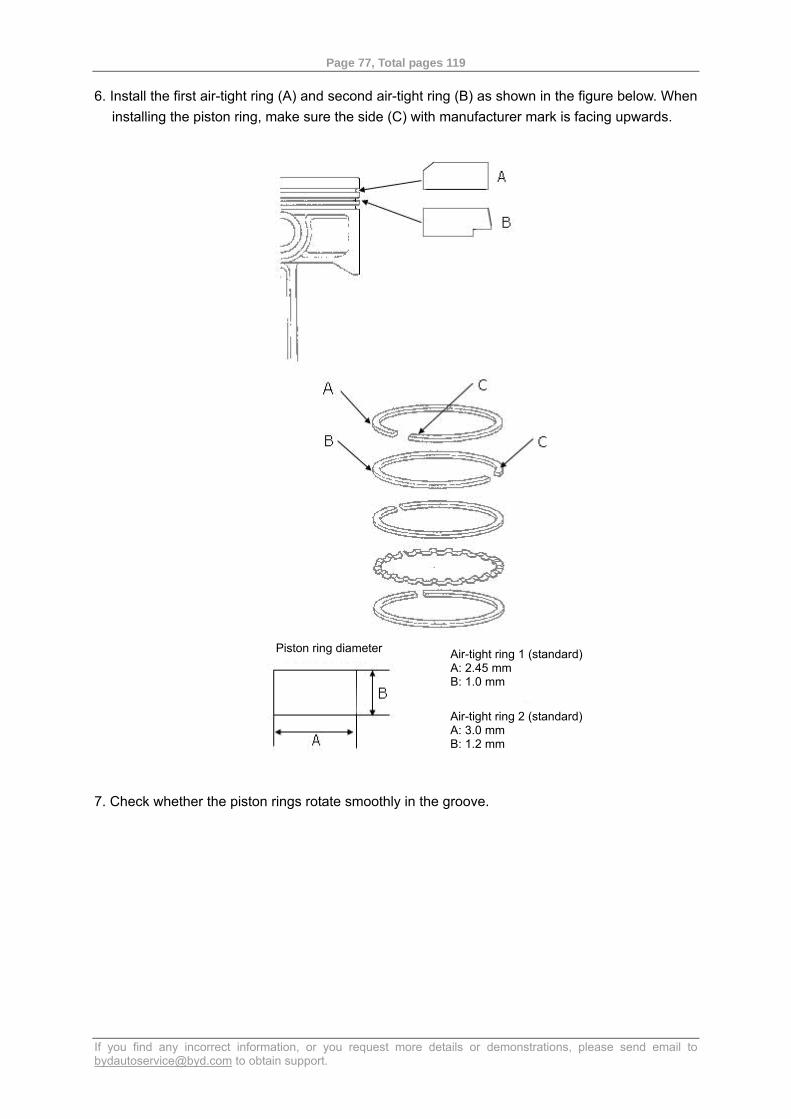
6. Install the first air-tight ring (A) and second air-tight ring (B) as shown in the figure below. When installing the piston ring, make sure the side (C) with manufacturer mark is facing upwards.
7. Check whether the piston rings rotate smoothly in the groove.
Piston ring diameter Air-tight ring 1 (standard) A: 2.45 mm B: 1.0 mm
Air-tight ring 2 (standard) A: 3.0 mm B: 1.2 mm
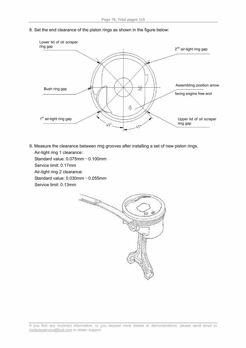
Page 78, Total pages 119
If you find any incorrect information, or you request more details or demonstrations, please send email to [email protected] to obtain support.
8. Set the end clearance of the piston rings as shown in the figure below:
9. Measure the clearance between ring grooves after installing a set of new piston rings. Air-tight ring 1 clearance: Standard value: 0.075mm~0.100mm Service limit: 0.17mm Air-tight ring 2 clearance: Standard value: 0.030mm~0.055mm Service limit: 0.13mm
2nd air-tight ring gap
Bush ring gap
1st air-tight ring gap
Assembling position arrow
facing engine free end
Upper lid of oil scraper ring gap
Lower lid of oil scraper ring gap
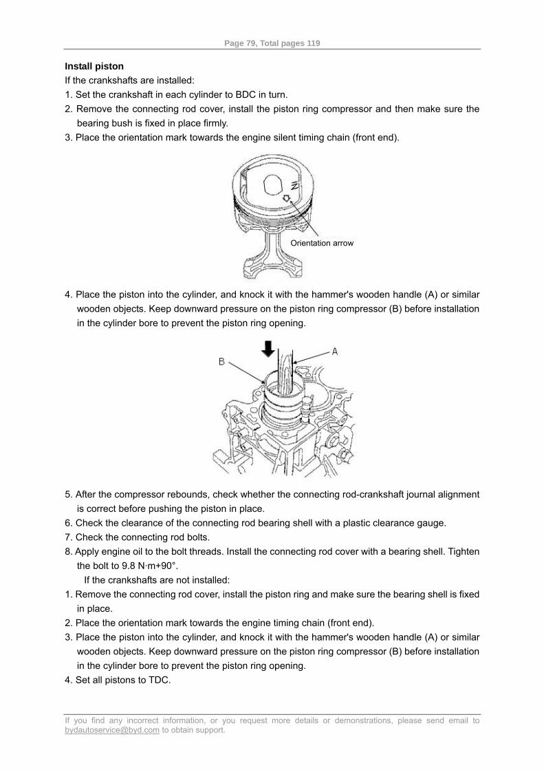
Page 79, Total pages 119
If you find any incorrect information, or you request more details or demonstrations, please send email to [email protected] to obtain support.
Install piston If the crankshafts are installed: 1. Set the crankshaft in each cylinder to BDC in turn. 2. Remove the connecting rod cover, install the piston ring compressor and then make sure the
bearing bush is fixed in place firmly. 3. Place the orientation mark towards the engine silent timing chain (front end).
4. Place the piston into the cylinder, and knock it with the hammer's wooden handle (A) or similar
wooden objects. Keep downward pressure on the piston ring compressor (B) before installation in the cylinder bore to prevent the piston ring opening.
5. After the compressor rebounds, check whether the connecting rod-crankshaft journal alignment
is correct before pushing the piston in place. 6. Check the clearance of the connecting rod bearing shell with a plastic clearance gauge. 7. Check the connecting rod bolts. 8. Apply engine oil to the bolt threads. Install the connecting rod cover with a bearing shell. Tighten
the bolt to 9.8 N·m+90°. If the crankshafts are not installed:
1. Remove the connecting rod cover, install the piston ring and make sure the bearing shell is fixed in place.
2. Place the orientation mark towards the engine timing chain (front end). 3. Place the piston into the cylinder, and knock it with the hammer's wooden handle (A) or similar
wooden objects. Keep downward pressure on the piston ring compressor (B) before installation in the cylinder bore to prevent the piston ring opening.
4. Set all pistons to TDC.
Orientation arrow
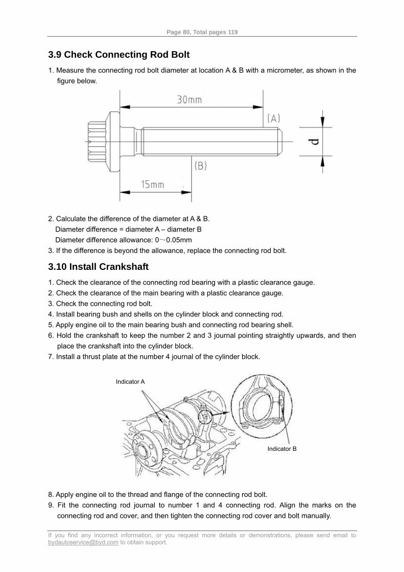
Page 80, Total pages 119
If you find any incorrect information, or you request more details or demonstrations, please send email to [email protected] to obtain support.
3.9 Check Connecting Rod Bolt 1. Measure the connecting rod bolt diameter at location A & B with a micrometer, as shown in the
figure below.
2. Calculate the difference of the diameter at A & B.
Diameter difference = diameter A – diameter B Diameter difference allowance: 0~0.05mm
3. If the difference is beyond the allowance, replace the connecting rod bolt.
3.10 Install Crankshaft 1. Check the clearance of the connecting rod bearing with a plastic clearance gauge. 2. Check the clearance of the main bearing with a plastic clearance gauge. 3. Check the connecting rod bolt. 4. Install bearing bush and shells on the cylinder block and connecting rod. 5. Apply engine oil to the main bearing bush and connecting rod bearing shell. 6. Hold the crankshaft to keep the number 2 and 3 journal pointing straightly upwards, and then
place the crankshaft into the cylinder block. 7. Install a thrust plate at the number 4 journal of the cylinder block.
8. Apply engine oil to the thread and flange of the connecting rod bolt. 9. Fit the connecting rod journal to number 1 and 4 connecting rod. Align the marks on the
connecting rod and cover, and then tighten the connecting rod cover and bolt manually.
Indicator A
Indicator B
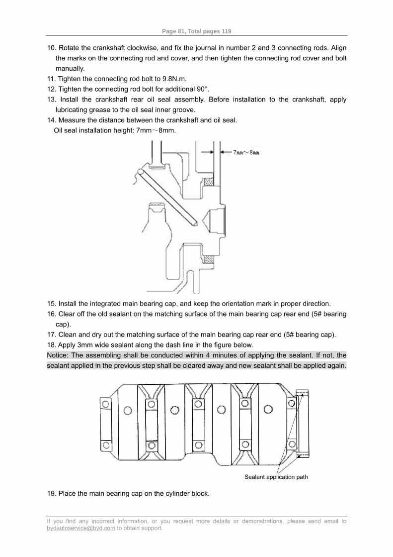
Page 81, Total pages 119
If you find any incorrect information, or you request more details or demonstrations, please send email to [email protected] to obtain support.
10. Rotate the crankshaft clockwise, and fix the journal in number 2 and 3 connecting rods. Align the marks on the connecting rod and cover, and then tighten the connecting rod cover and bolt manually.
11. Tighten the connecting rod bolt to 9.8N.m. 12. Tighten the connecting rod bolt for additional 90°. 13. Install the crankshaft rear oil seal assembly. Before installation to the crankshaft, apply
lubricating grease to the oil seal inner groove. 14. Measure the distance between the crankshaft and oil seal.
Oil seal installation height: 7mm~8mm.
15. Install the integrated main bearing cap, and keep the orientation mark in proper direction. 16. Clear off the old sealant on the matching surface of the main bearing cap rear end (5# bearing
cap). 17. Clean and dry out the matching surface of the main bearing cap rear end (5# bearing cap). 18. Apply 3mm wide sealant along the dash line in the figure below. Notice: The assembling shall be conducted within 4 minutes of applying the sealant. If not, the sealant applied in the previous step shall be cleared away and new sealant shall be applied again.
19. Place the main bearing cap on the cylinder block.
Sealant application path
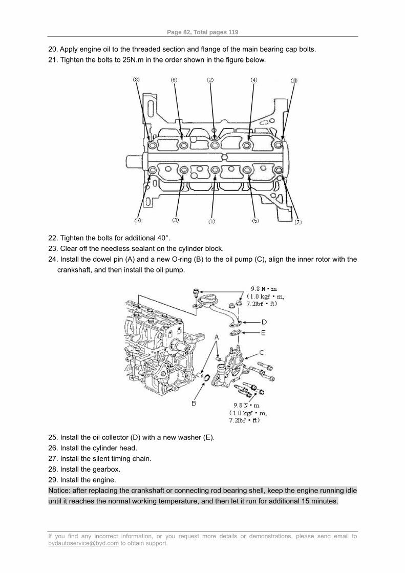
Page 82, Total pages 119
If you find any incorrect information, or you request more details or demonstrations, please send email to [email protected] to obtain support.
20. Apply engine oil to the threaded section and flange of the main bearing cap bolts. 21. Tighten the bolts to 25N.m in the order shown in the figure below.
22. Tighten the bolts for additional 40°. 23. Clear off the needless sealant on the cylinder block. 24. Install the dowel pin (A) and a new O-ring (B) to the oil pump (C), align the inner rotor with the
crankshaft, and then install the oil pump.
25. Install the oil collector (D) with a new washer (E). 26. Install the cylinder head. 27. Install the silent timing chain. 28. Install the gearbox. 29. Install the engine. Notice: after replacing the crankshaft or connecting rod bearing shell, keep the engine running idle until it reaches the normal working temperature, and then let it run for additional 15 minutes.
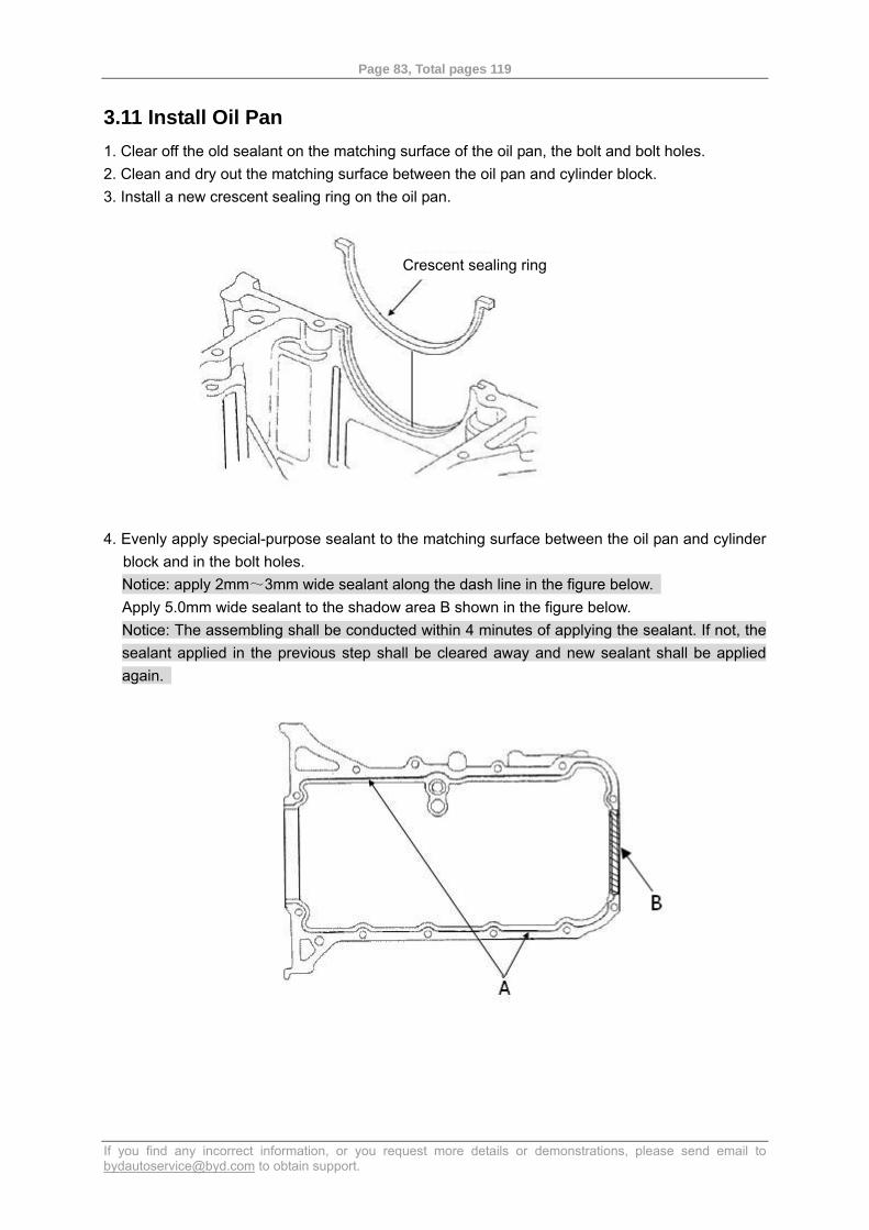
Page 83, Total pages 119
If you find any incorrect information, or you request more details or demonstrations, please send email to [email protected] to obtain support.
3.11 Install Oil Pan 1. Clear off the old sealant on the matching surface of the oil pan, the bolt and bolt holes. 2. Clean and dry out the matching surface between the oil pan and cylinder block. 3. Install a new crescent sealing ring on the oil pan.
4. Evenly apply special-purpose sealant to the matching surface between the oil pan and cylinder block and in the bolt holes. Notice: apply 2mm~3mm wide sealant along the dash line in the figure below. Apply 5.0mm wide sealant to the shadow area B shown in the figure below. Notice: The assembling shall be conducted within 4 minutes of applying the sealant. If not, the sealant applied in the previous step shall be cleared away and new sealant shall be applied again.
Crescent sealing ring
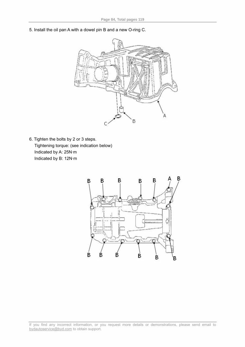
Page 84, Total pages 119
If you find any incorrect information, or you request more details or demonstrations, please send email to [email protected] to obtain support.
5. Install the oil pan A with a dowel pin B and a new O-ring C.
6. Tighten the bolts by 2 or 3 steps. Tightening torque: (see indication below) Indicated by A: 25N·m Indicated by B: 12N·m
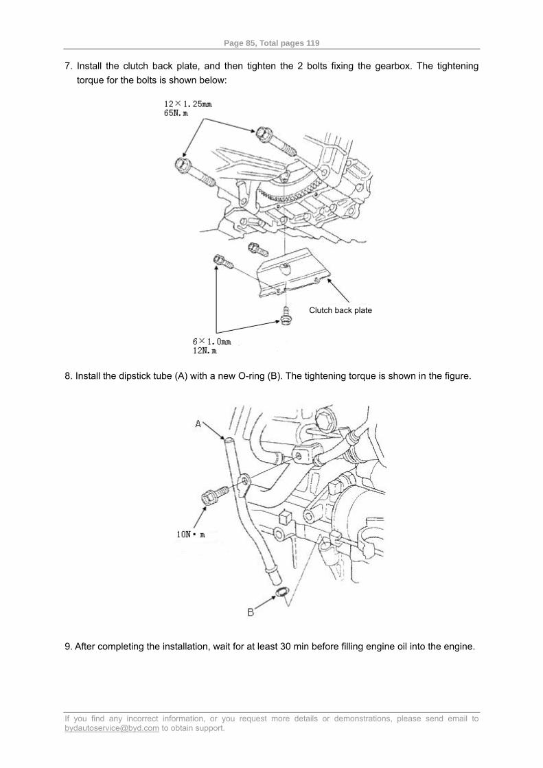
Page 85, Total pages 119
If you find any incorrect information, or you request more details or demonstrations, please send email to [email protected] to obtain support.
7. Install the clutch back plate, and then tighten the 2 bolts fixing the gearbox. The tightening torque for the bolts is shown below:
8. Install the dipstick tube (A) with a new O-ring (B). The tightening torque is shown in the figure.
9. After completing the installation, wait for at least 30 min before filling engine oil into the engine.
Clutch back plate
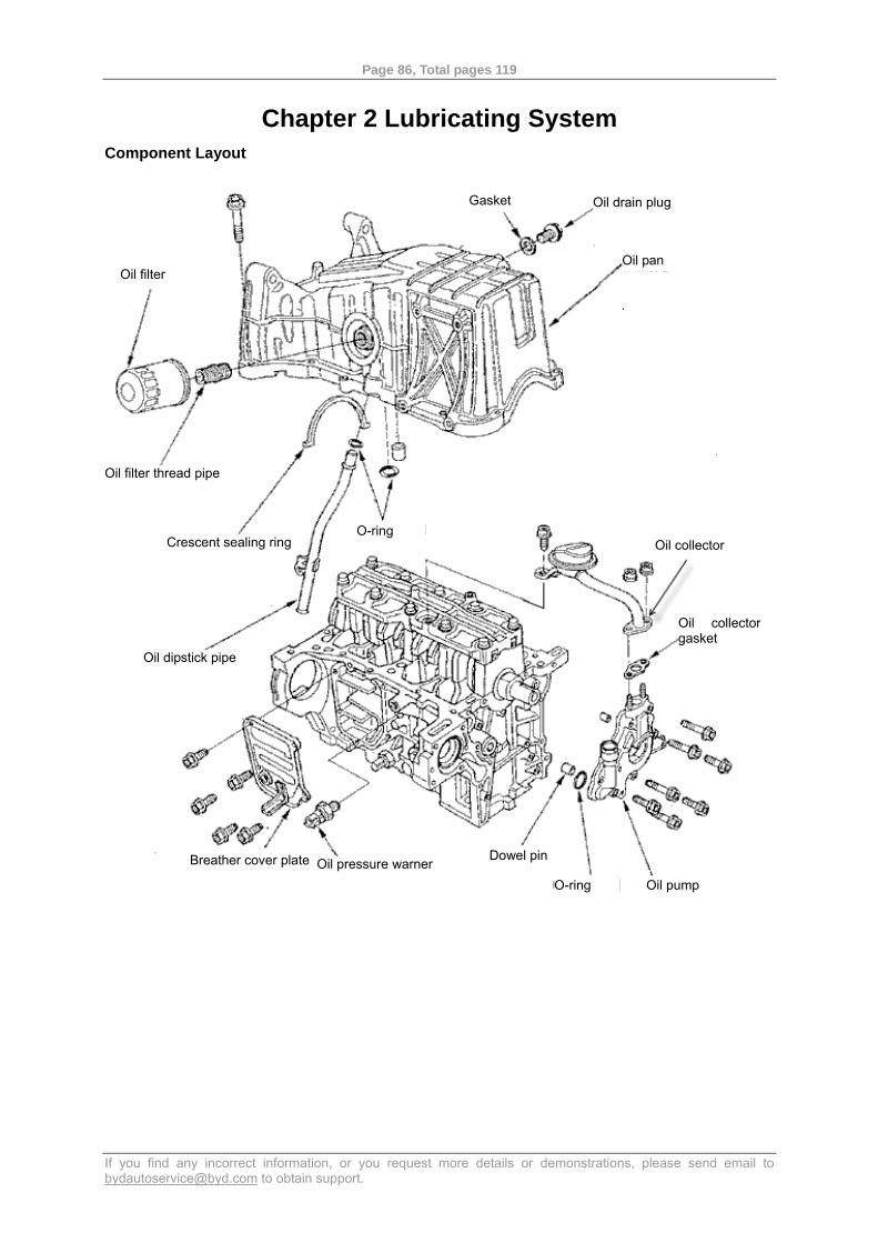
Page 86, Total pages 119
If you find any incorrect information, or you request more details or demonstrations, please send email to [email protected] to obtain support.
Chapter 2 Lubricating System Component Layout
Oil drain plug
Oil pan
Gasket
Oil filter
Crescent sealing ring O-ring
Oil collector
Oil collector gasket
Oil dipstick pipe
Oil filter thread pipe
Breather cover plate
O-ring Oil pump Oil pressure warner Dowel pin
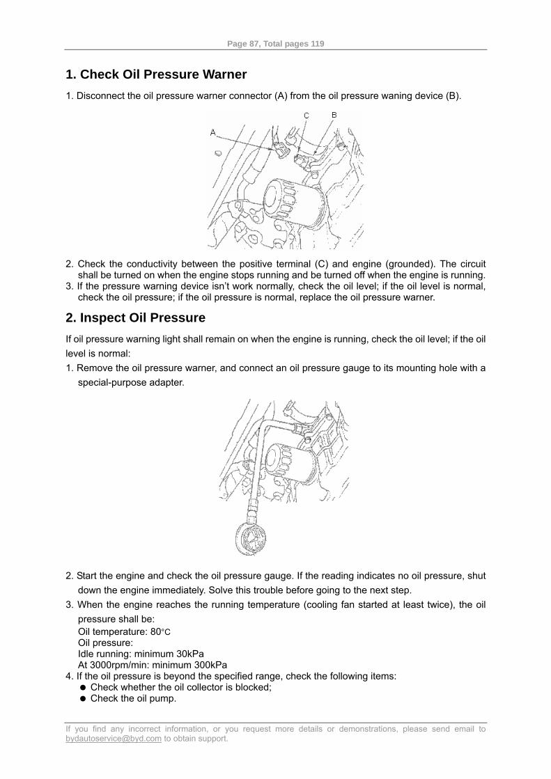
Page 87, Total pages 119
If you find any incorrect information, or you request more details or demonstrations, please send email to [email protected] to obtain support.
1. Check Oil Pressure Warner 1. Disconnect the oil pressure warner connector (A) from the oil pressure waning device (B).
2. Check the conductivity between the positive terminal (C) and engine (grounded). The circuit
shall be turned on when the engine stops running and be turned off when the engine is running. 3. If the pressure warning device isn’t work normally, check the oil level; if the oil level is normal,
check the oil pressure; if the oil pressure is normal, replace the oil pressure warner.
2. Inspect Oil Pressure If oil pressure warning light shall remain on when the engine is running, check the oil level; if the oil level is normal: 1. Remove the oil pressure warner, and connect an oil pressure gauge to its mounting hole with a
special-purpose adapter.
2. Start the engine and check the oil pressure gauge. If the reading indicates no oil pressure, shut
down the engine immediately. Solve this trouble before going to the next step. 3. When the engine reaches the running temperature (cooling fan started at least twice), the oil
pressure shall be: Oil temperature: 80°C Oil pressure: Idle running: minimum 30kPa At 3000rpm/min: minimum 300kPa
4. If the oil pressure is beyond the specified range, check the following items: Check whether the oil collector is blocked; Check the oil pump.
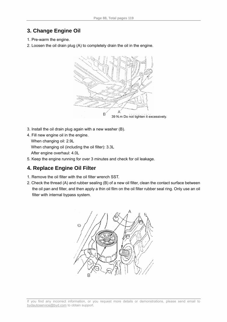
Page 88, Total pages 119
If you find any incorrect information, or you request more details or demonstrations, please send email to [email protected] to obtain support.
3. Change Engine Oil 1. Pre-warm the engine. 2. Loosen the oil drain plug (A) to completely drain the oil in the engine.
3. Install the oil drain plug again with a new washer (B). 4. Fill new engine oil in the engine.
When changing oil: 2.9L When changing oil (including the oil filter): 3.3L After engine overhaul: 4.0L
5. Keep the engine running for over 3 minutes and check for oil leakage.
4. Replace Engine Oil Filter 1. Remove the oil filter with the oil filter wrench SST. 2. Check the thread (A) and rubber sealing (B) of a new oil filter, clean the contact surface between
the oil pan and filter, and then apply a thin oil film on the oil filter rubber seal ring. Only use an oil filter with internal bypass system.
39 N.m Do not tighten it excessively.
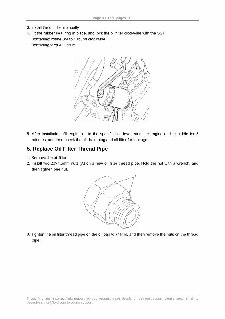
Page 89, Total pages 119
If you find any incorrect information, or you request more details or demonstrations, please send email to [email protected] to obtain support.
3. Install the oil filter manually. 4. Fit the rubber seal ring in place, and lock the oil filter clockwise with the SST.
Tightening: rotate 3/4 to 1 round clockwise. Tightening torque: 12N.m
5. After installation, fill engine oil to the specified oil level, start the engine and let it idle for 3
minutes, and then check the oil drain plug and oil filter for leakage.
5. Replace Oil Filter Thread Pipe 1. Remove the oil filter. 2. Install two 20×1.5mm nuts (A) on a new oil filter thread pipe. Hold the nut with a wrench, and
then tighten one nut.
3. Tighten the oil filter thread pipe on the oil pan to 74N.m, and then remove the nuts on the thread
pipe.

Page 90, Total pages 119
If you find any incorrect information, or you request more details or demonstrations, please send email to [email protected] to obtain support.
6. Overhaul Oil Pump Exploded view
Pump housing Dowel pin
O-ring
Outer rotor
Inner rotor
Oil pump cover
Spring
Pressure relief valve The valve shall slide freely in the housing. Replace the valve if any scratch.
Sealing bolt 20N.m

Page 91, Total pages 119
If you find any incorrect information, or you request more details or demonstrations, please send email to [email protected] to obtain support.
Removal Procedure 1. Remove the silent timing chain. 2. Remove the oil collector (A) and then the oil pump (B).
Inspection 1. Remove the pump cover. 2. Check the radial clearance between the inner rotor (A) and outer rotor (B). If the radial
clearance is beyond the service limit, replace the oil pump. Inner rotor-outer rotor radial clearance: Standard: 0.075~0.15mm Service limit: 0.18mm
3. Check the axial clearance between the rotor (A) and pump housing (B). If the axial clearance is
beyond the service limit, replace the oil pump.
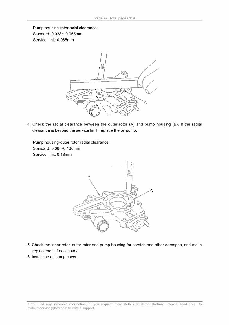
Page 92, Total pages 119
If you find any incorrect information, or you request more details or demonstrations, please send email to [email protected] to obtain support.
Pump housing-rotor axial clearance: Standard: 0.028~0.065mm Service limit: 0.085mm
4. Check the radial clearance between the outer rotor (A) and pump housing (B). If the radial
clearance is beyond the service limit, replace the oil pump.
Pump housing-outer rotor radial clearance: Standard: 0.06~0.136mm Service limit: 0.18mm
5. Check the inner rotor, outer rotor and pump housing for scratch and other damages, and make
replacement if necessary. 6. Install the oil pump cover.
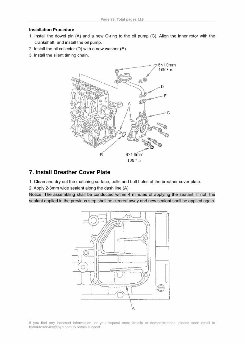
Page 93, Total pages 119
If you find any incorrect information, or you request more details or demonstrations, please send email to [email protected] to obtain support.
Installation Procedure 1. Install the dowel pin (A) and a new O-ring to the oil pump (C). Align the inner rotor with the
crankshaft, and install the oil pump. 2. Install the oil collector (D) with a new washer (E). 3. Install the silent timing chain.
7. Install Breather Cover Plate 1. Clean and dry out the matching surface, bolts and bolt holes of the breather cover plate. 2. Apply 2-3mm wide sealant along the dash line (A). Notice: The assembling shall be conducted within 4 minutes of applying the sealant. If not, the sealant applied in the previous step shall be cleared away and new sealant shall be applied again.
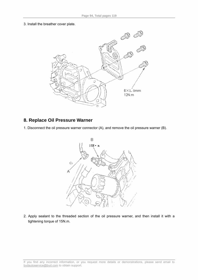
Page 94, Total pages 119
If you find any incorrect information, or you request more details or demonstrations, please send email to [email protected] to obtain support.
3. Install the breather cover plate.
8. Replace Oil Pressure Warner 1. Disconnect the oil pressure warner connector (A), and remove the oil pressure warner (B).
2. Apply sealant to the threaded section of the oil pressure warner, and then install it with a tightening torque of 15N.m.
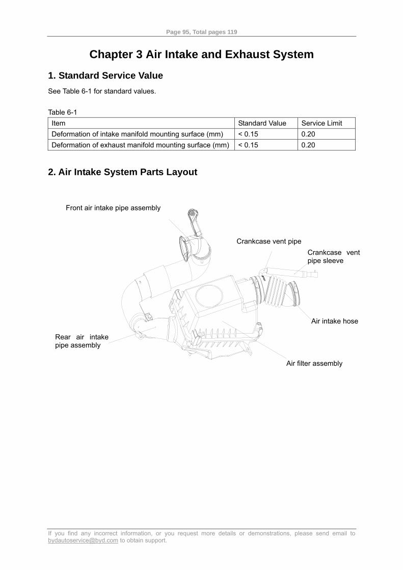
Page 95, Total pages 119
If you find any incorrect information, or you request more details or demonstrations, please send email to [email protected] to obtain support.
Chapter 3 Air Intake and Exhaust System
1. Standard Service Value See Table 6-1 for standard values. Table 6-1 Item Standard Value Service Limit Deformation of intake manifold mounting surface (mm) < 0.15 0.20 Deformation of exhaust manifold mounting surface (mm) < 0.15 0.20
2. Air Intake System Parts Layout
曲轴箱通风管
曲轴箱通风管护套
进气软管
空气滤清器总成
进气管后段总成
进气管前段总成
Crankcase vent pipe
Front air intake pipe assembly
Crankcase vent pipe sleeve
Air intake hose
Air filter assembly
Rear air intakepipe assembly
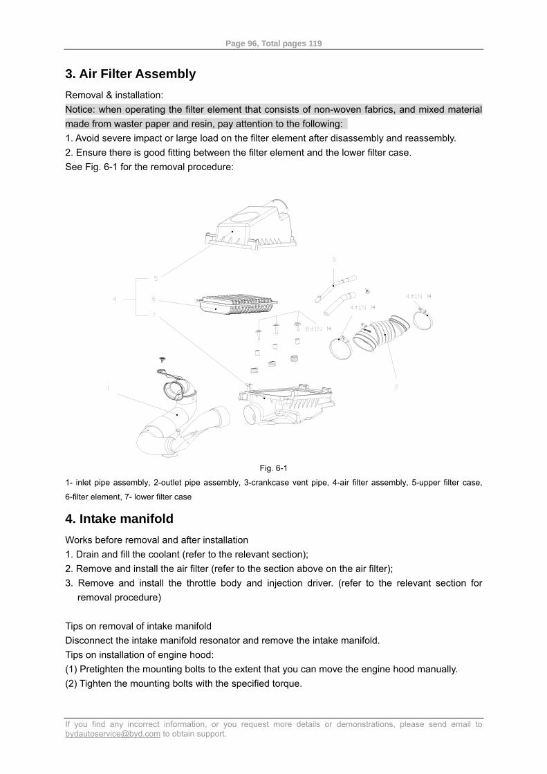
Page 96, Total pages 119
If you find any incorrect information, or you request more details or demonstrations, please send email to [email protected] to obtain support.
3. Air Filter Assembly Removal & installation: Notice: when operating the filter element that consists of non-woven fabrics, and mixed material made from waster paper and resin, pay attention to the following: 1. Avoid severe impact or large load on the filter element after disassembly and reassembly. 2. Ensure there is good fitting between the filter element and the lower filter case. See Fig. 6-1 for the removal procedure:
.
.
.
Fig. 6-1
1- inlet pipe assembly, 2-outlet pipe assembly, 3-crankcase vent pipe, 4-air filter assembly, 5-upper filter case,
6-filter element, 7- lower filter case
4. Intake manifold Works before removal and after installation 1. Drain and fill the coolant (refer to the relevant section); 2. Remove and install the air filter (refer to the section above on the air filter); 3. Remove and install the throttle body and injection driver. (refer to the relevant section for
removal procedure) Tips on removal of intake manifold Disconnect the intake manifold resonator and remove the intake manifold. Tips on installation of engine hood: (1) Pretighten the mounting bolts to the extent that you can move the engine hood manually. (2) Tighten the mounting bolts with the specified torque.
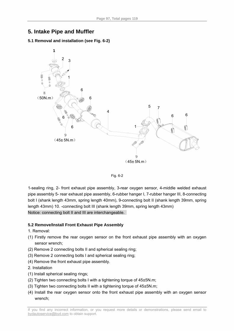
Page 97, Total pages 119
If you find any incorrect information, or you request more details or demonstrations, please send email to [email protected] to obtain support.
5. Intake Pipe and Muffler 5.1 Removal and installation (see Fig. 6-2)
6
7
1
4
6
6
6
1
3
2
1
6
5
9(45± 5N.m)
8(50N.m)
9(45± 5N.m)
6
Fig. 6-2
1-sealing ring, 2- front exhaust pipe assembly, 3-rear oxygen sensor, 4-middle welded exhaust pipe assembly 5- rear exhaust pipe assembly, 6-rubber hanger I, 7-rubber hanger III, 8-connecting bolt I (shank length 43mm, spring length 40mm), 9-connecting bolt II (shank length 39mm, spring length 43mm) 10. -connecting bolt III (shank length 39mm, spring length 43mm) Notice: connecting bolt II and III are interchangeable. 5.2 Remove/Install Front Exhaust Pipe Assembly 1. Removal: (1) Firstly remove the rear oxygen sensor on the front exhaust pipe assembly with an oxygen
sensor wrench; (2) Remove 2 connecting bolts II and spherical sealing ring; (3) Remove 2 connecting bolts I and spherical sealing ring; (4) Remove the front exhaust pipe assembly. 2. Installation (1) Install spherical sealing rings; (2) Tighten two connecting bolts I with a tightening torque of 45±5N.m; (3) Tighten two connecting bolts II with a tightening torque of 45±5N.m; (4) Install the rear oxygen sensor onto the front exhaust pipe assembly with an oxygen sensor
wrench;
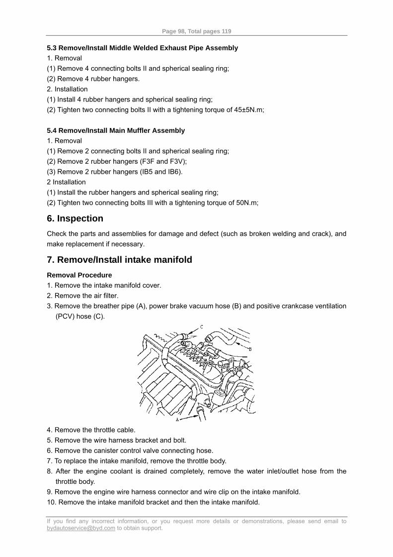
Page 98, Total pages 119
If you find any incorrect information, or you request more details or demonstrations, please send email to [email protected] to obtain support.
5.3 Remove/Install Middle Welded Exhaust Pipe Assembly 1. Removal (1) Remove 4 connecting bolts II and spherical sealing ring; (2) Remove 4 rubber hangers. 2. Installation (1) Install 4 rubber hangers and spherical sealing ring; (2) Tighten two connecting bolts II with a tightening torque of 45±5N.m; 5.4 Remove/Install Main Muffler Assembly 1. Removal (1) Remove 2 connecting bolts II and spherical sealing ring; (2) Remove 2 rubber hangers (F3F and F3V); (3) Remove 2 rubber hangers (IB5 and IB6). 2 Installation (1) Install the rubber hangers and spherical sealing ring; (2) Tighten two connecting bolts III with a tightening torque of 50N.m;
6. Inspection Check the parts and assemblies for damage and defect (such as broken welding and crack), and make replacement if necessary.
7. Remove/Install intake manifold Removal Procedure 1. Remove the intake manifold cover. 2. Remove the air filter. 3. Remove the breather pipe (A), power brake vacuum hose (B) and positive crankcase ventilation
(PCV) hose (C).
4. Remove the throttle cable. 5. Remove the wire harness bracket and bolt. 6. Remove the canister control valve connecting hose. 7. To replace the intake manifold, remove the throttle body. 8. After the engine coolant is drained completely, remove the water inlet/outlet hose from the
throttle body. 9. Remove the engine wire harness connector and wire clip on the intake manifold. 10. Remove the intake manifold bracket and then the intake manifold.
Page 99, Total pages 119
If you find any incorrect information, or you request more details or demonstrations, please send email to [email protected] to obtain support.
Installation Procedure 1. Install the intake manifold with a new sealing washer, and then tighten the bolts and nuts by 2-3
steps in alternating pattern, starting from the innermost bolt, with a tightening torque of 25N.m. 2. Install the intake manifold bracket. 3. If the water inlet/outlet hose have been removed on the throttle body, install them properly. 4. If the throttle body is removed, install it with a new sealing washer for throttle body. 5. Install the canister control valve connecting hose. 6. Install the wire harness bracket and bolt. 7. Install the throttle cable and adjust it. 8. Install the breather pipe, power brake vacuum hose and positive crankcase ventilation (PCV)
hose. 9. Install the air filter. 10. Install the intake manifold cover. 11. Upon completion of assembling, check whether all pipes, hoses and connectors are connected
properly. 12. If the engine coolant is drained completely, fill the coolant into the radiator again while leaving
the heater valve open to discharge the air in the cooling system.
8. Remove/Install Exhaust Manifold 1. Remove the insulation cover and bracket for the exhaust manifold, and then remove the
exhaust manifold. 2. Install the exhaust manifold and then tighten the bolts and nuts by 2-3 steps in alternating
pattern, starting from the innermost bolt. 3. Install the other parts in the reverse sequence of removal.
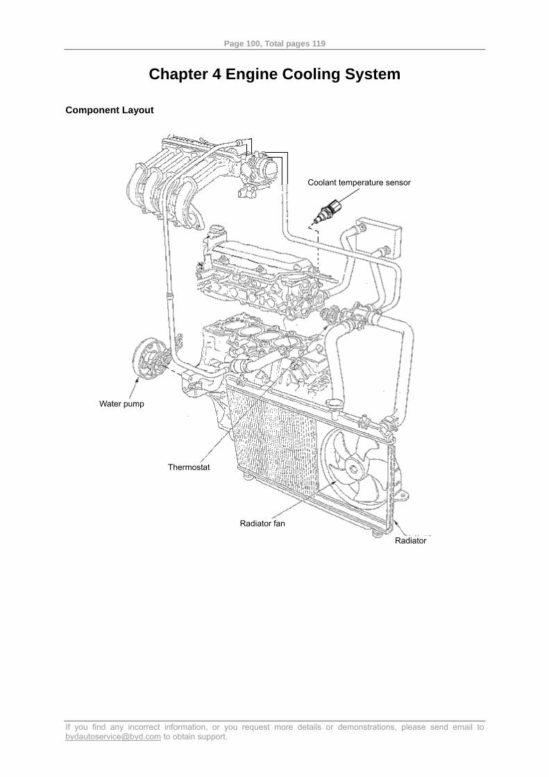
Page 100, Total pages 119
If you find any incorrect information, or you request more details or demonstrations, please send email to [email protected] to obtain support.
Chapter 4 Engine Cooling System Component Layout
Coolant temperature sensor
Water pump
Thermostat
Radiator
Radiator fan
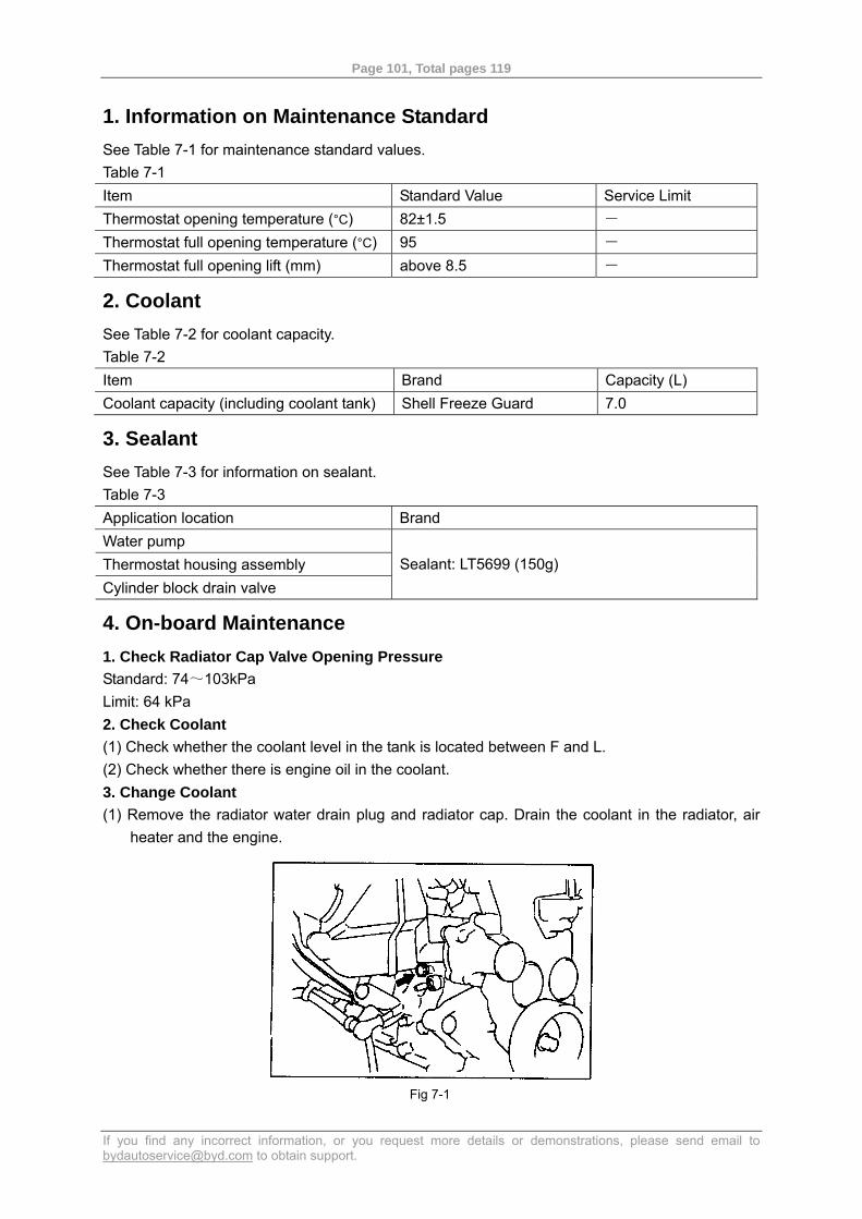
Page 101, Total pages 119
If you find any incorrect information, or you request more details or demonstrations, please send email to [email protected] to obtain support.
1. Information on Maintenance Standard See Table 7-1 for maintenance standard values. Table 7-1 Item Standard Value Service Limit Thermostat opening temperature (°C) 82±1.5 - Thermostat full opening temperature (°C) 95 - Thermostat full opening lift (mm) above 8.5 -
2. Coolant See Table 7-2 for coolant capacity. Table 7-2 Item Brand Capacity (L) Coolant capacity (including coolant tank) Shell Freeze Guard 7.0
3. Sealant See Table 7-3 for information on sealant. Table 7-3 Application location Brand Water pump Thermostat housing assembly Cylinder block drain valve
Sealant: LT5699 (150g)
4. On-board Maintenance 1. Check Radiator Cap Valve Opening Pressure Standard: 74~103kPa Limit: 64 kPa 2. Check Coolant (1) Check whether the coolant level in the tank is located between F and L. (2) Check whether there is engine oil in the coolant. 3. Change Coolant (1) Remove the radiator water drain plug and radiator cap. Drain the coolant in the radiator, air
heater and the engine.
Fig 7-1
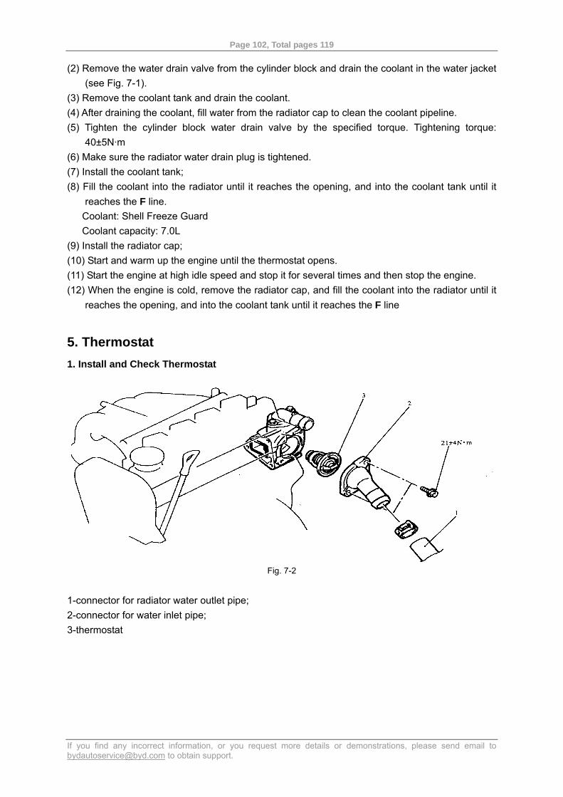
Page 102, Total pages 119
If you find any incorrect information, or you request more details or demonstrations, please send email to [email protected] to obtain support.
(2) Remove the water drain valve from the cylinder block and drain the coolant in the water jacket (see Fig. 7-1).
(3) Remove the coolant tank and drain the coolant. (4) After draining the coolant, fill water from the radiator cap to clean the coolant pipeline. (5) Tighten the cylinder block water drain valve by the specified torque. Tightening torque:
40±5N·m (6) Make sure the radiator water drain plug is tightened. (7) Install the coolant tank; (8) Fill the coolant into the radiator until it reaches the opening, and into the coolant tank until it
reaches the F line. Coolant: Shell Freeze Guard Coolant capacity: 7.0L
(9) Install the radiator cap; (10) Start and warm up the engine until the thermostat opens. (11) Start the engine at high idle speed and stop it for several times and then stop the engine. (12) When the engine is cold, remove the radiator cap, and fill the coolant into the radiator until it
reaches the opening, and into the coolant tank until it reaches the F line
5. Thermostat 1. Install and Check Thermostat
Fig. 7-2
1-connector for radiator water outlet pipe; 2-connector for water inlet pipe; 3-thermostat
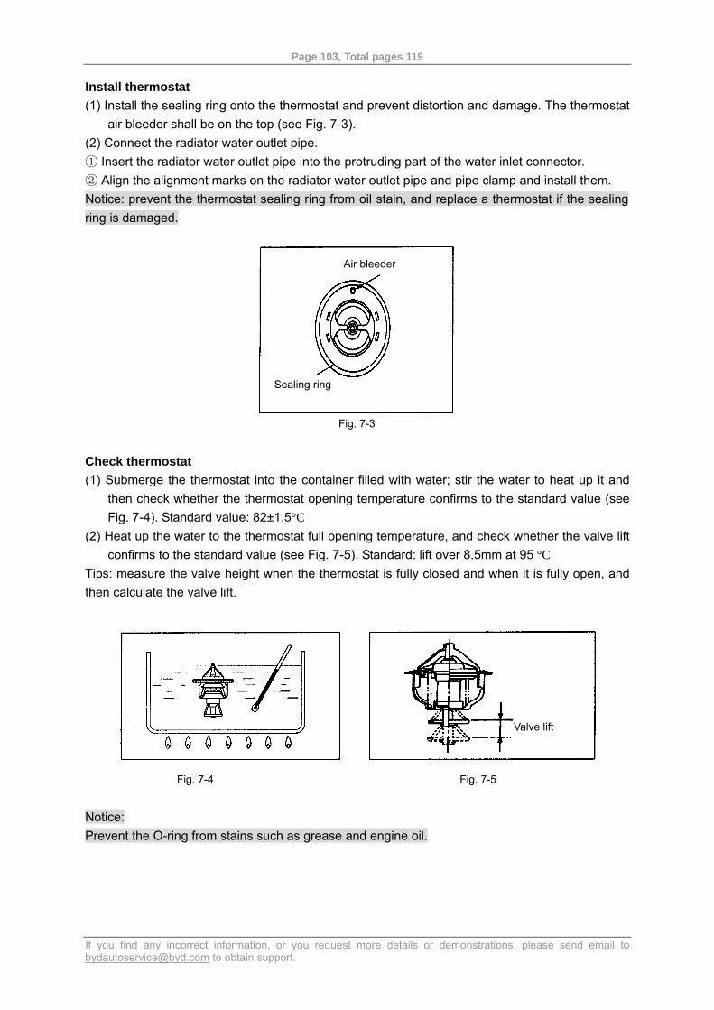
Page 103, Total pages 119
If you find any incorrect information, or you request more details or demonstrations, please send email to [email protected] to obtain support.
Install thermostat (1) Install the sealing ring onto the thermostat and prevent distortion and damage. The thermostat
air bleeder shall be on the top (see Fig. 7-3). (2) Connect the radiator water outlet pipe. ① Insert the radiator water outlet pipe into the protruding part of the water inlet connector. ② Align the alignment marks on the radiator water outlet pipe and pipe clamp and install them. Notice: prevent the thermostat sealing ring from oil stain, and replace a thermostat if the sealing ring is damaged.
Fig. 7-3
Check thermostat (1) Submerge the thermostat into the container filled with water; stir the water to heat up it and
then check whether the thermostat opening temperature confirms to the standard value (see Fig. 7-4). Standard value: 82±1.5°C
(2) Heat up the water to the thermostat full opening temperature, and check whether the valve lift confirms to the standard value (see Fig. 7-5). Standard: lift over 8.5mm at 95 °C
Tips: measure the valve height when the thermostat is fully closed and when it is fully open, and then calculate the valve lift.
Fig. 7-4 Fig. 7-5
Notice: Prevent the O-ring from stains such as grease and engine oil.
Air bleeder
Sealing ring
Valve lift
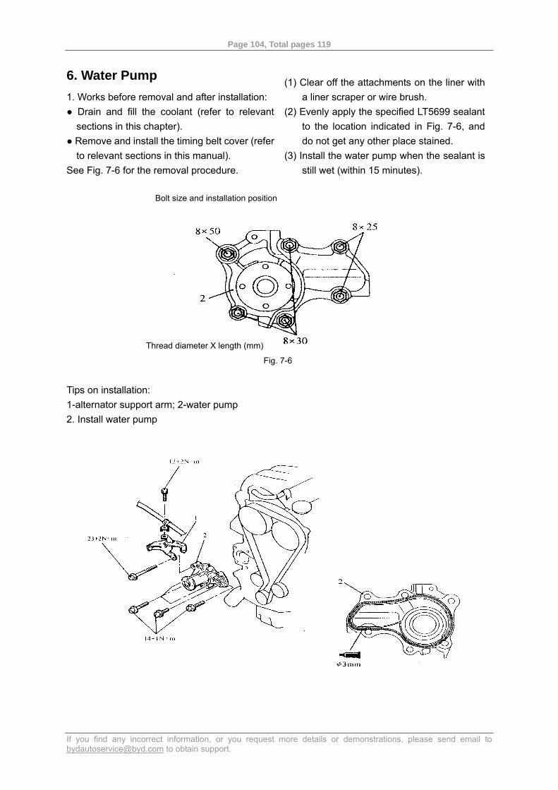
Page 104, Total pages 119
If you find any incorrect information, or you request more details or demonstrations, please send email to [email protected] to obtain support.
6. Water Pump 1. Works before removal and after installation: ● Drain and fill the coolant (refer to relevant
sections in this chapter). ● Remove and install the timing belt cover (refer
to relevant sections in this manual). See Fig. 7-6 for the removal procedure.
(1) Clear off the attachments on the liner with
a liner scraper or wire brush. (2) Evenly apply the specified LT5699 sealant
to the location indicated in Fig. 7-6, and do not get any other place stained.
(3) Install the water pump when the sealant is still wet (within 15 minutes).
Fig. 7-6
Tips on installation: 1-alternator support arm; 2-water pump 2. Install water pump
Bolt size and installation position
Thread diameter X length (mm)
Page 105, Total pages 119
If you find any incorrect information, or you request more details or demonstrations, please send email to [email protected] to obtain support.
7. Water Inlet/Outlet Hose Works before removal and after installation ● Drain and fill the coolant (refer to relevant sections in this chapter) ● Remove and install the engine hood (refer to relevant sections in this manual) ● Remove and install the lower cover ● Remove and install the battery and battery bracket. See Fig. 7-7 for the removal procedure. Tips on removal (1) Disconnect the radiator water inlet/outlet pipe, and make alignment marks on the pipes and
clamps before removal. (2) To remove the water inlet pipe, remove the bolts for pressure stabilizing box resonator and
move the resonator out of the operation range. (see Fig. 7-8) Remove the water inlet pipe (see Fig. 7-8)
Tips on installation (1) Install O-ring
Tips on installation (1) Soak the periphery and inside of the O-ring with water and then insert it in place (see Fig. 7-9). (2) Install the thermostat housing assembly
a. Clear off the attachments on the liner with a liner scraper or wire brush. b. Evenly apply the specified sealant on the mounting surface for sealing, and do not get any other place stained. c. Install the thermostat when the sealant is still wet (within 15 minutes).
(3) Connect radiator water inlet/outlet pipe a. Insert the water inlet/outlet pipe into the protruding part of the connectors. b. Align the alignment marks on the radiator water inlet pipe and pipe clamp and install them.
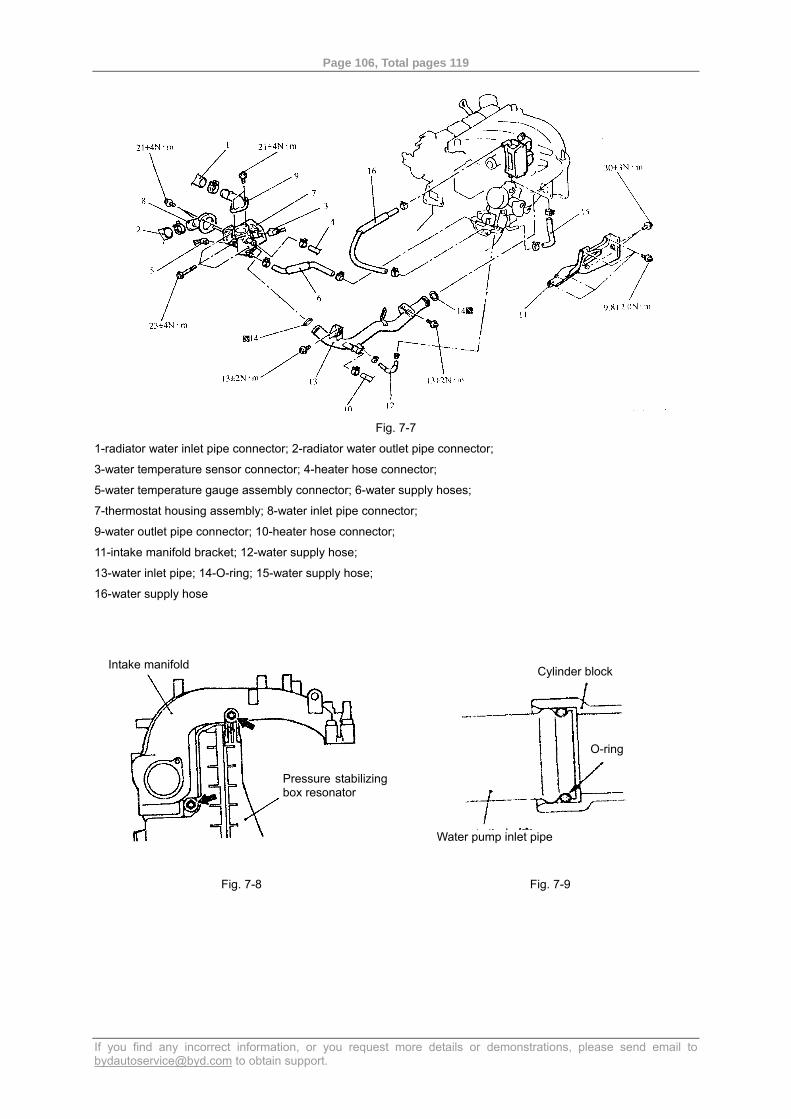
Page 106, Total pages 119
If you find any incorrect information, or you request more details or demonstrations, please send email to [email protected] to obtain support.
Fig. 7-7
1-radiator water inlet pipe connector; 2-radiator water outlet pipe connector;
3-water temperature sensor connector; 4-heater hose connector;
5-water temperature gauge assembly connector; 6-water supply hoses;
7-thermostat housing assembly; 8-water inlet pipe connector;
9-water outlet pipe connector; 10-heater hose connector;
11-intake manifold bracket; 12-water supply hose;
13-water inlet pipe; 14-O-ring; 15-water supply hose;
16-water supply hose
Fig. 7-8
Fig. 7-9
Pressure stabilizingbox resonator
Intake manifold
Water pump inlet pipe
O-ring
Cylinder block
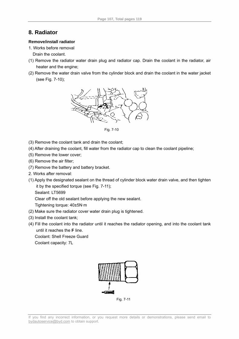
Page 107, Total pages 119
If you find any incorrect information, or you request more details or demonstrations, please send email to [email protected] to obtain support.
8. Radiator Remove/install radiator 1. Works before removal
Drain the coolant. (1) Remove the radiator water drain plug and radiator cap. Drain the coolant in the radiator, air
heater and the engine; (2) Remove the water drain valve from the cylinder block and drain the coolant in the water jacket
(see Fig. 7-10);
Fig. 7-10
(3) Remove the coolant tank and drain the coolant; (4) After draining the coolant, fill water from the radiator cap to clean the coolant pipeline; (5) Remove the lower cover; (6) Remove the air filter; (7) Remove the battery and battery bracket. 2. Works after removal: (1) Apply the designated sealant on the thread of cylinder block water drain valve, and then tighten
it by the specified torque (see Fig. 7-11); Sealant: LT5699 Clear off the old sealant before applying the new sealant. Tightening torque: 40±5N·m
(2) Make sure the radiator cover water drain plug is tightened. (3) Install the coolant tank; (4) Fill the coolant into the radiator until it reaches the radiator opening, and into the coolant tank
until it reaches the F line. Coolant: Shell Freeze Guard Coolant capacity: 7L
Fig. 7-11
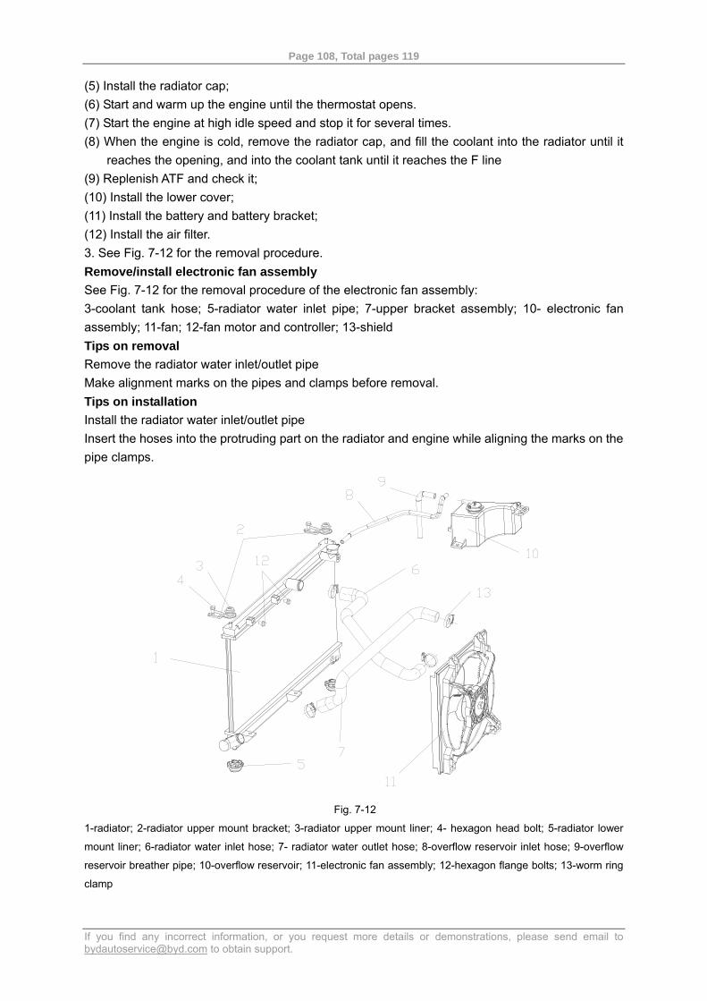
Page 108, Total pages 119
If you find any incorrect information, or you request more details or demonstrations, please send email to [email protected] to obtain support.
(5) Install the radiator cap; (6) Start and warm up the engine until the thermostat opens. (7) Start the engine at high idle speed and stop it for several times. (8) When the engine is cold, remove the radiator cap, and fill the coolant into the radiator until it
reaches the opening, and into the coolant tank until it reaches the F line (9) Replenish ATF and check it; (10) Install the lower cover; (11) Install the battery and battery bracket; (12) Install the air filter. 3. See Fig. 7-12 for the removal procedure. Remove/install electronic fan assembly See Fig. 7-12 for the removal procedure of the electronic fan assembly: 3-coolant tank hose; 5-radiator water inlet pipe; 7-upper bracket assembly; 10- electronic fan assembly; 11-fan; 12-fan motor and controller; 13-shield Tips on removal Remove the radiator water inlet/outlet pipe Make alignment marks on the pipes and clamps before removal. Tips on installation Install the radiator water inlet/outlet pipe Insert the hoses into the protruding part on the radiator and engine while aligning the marks on the pipe clamps.
Fig. 7-12
1-radiator; 2-radiator upper mount bracket; 3-radiator upper mount liner; 4- hexagon head bolt; 5-radiator lower
mount liner; 6-radiator water inlet hose; 7- radiator water outlet hose; 8-overflow reservoir inlet hose; 9-overflow
reservoir breather pipe; 10-overflow reservoir; 11-electronic fan assembly; 12-hexagon flange bolts; 13-worm ring
clamp
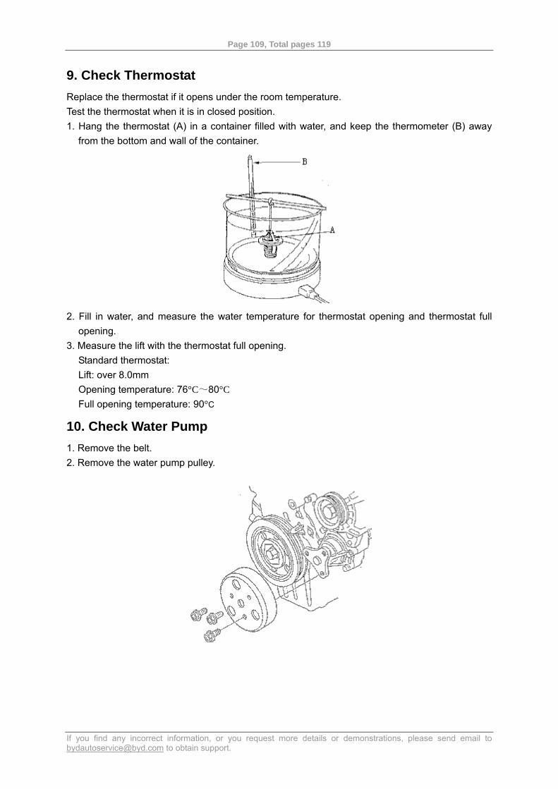
Page 109, Total pages 119
If you find any incorrect information, or you request more details or demonstrations, please send email to [email protected] to obtain support.
9. Check Thermostat Replace the thermostat if it opens under the room temperature. Test the thermostat when it is in closed position. 1. Hang the thermostat (A) in a container filled with water, and keep the thermometer (B) away
from the bottom and wall of the container.
2. Fill in water, and measure the water temperature for thermostat opening and thermostat full opening.
3. Measure the lift with the thermostat full opening. Standard thermostat: Lift: over 8.0mm Opening temperature: 76°C~80°C Full opening temperature: 90°C
10. Check Water Pump 1. Remove the belt. 2. Remove the water pump pulley.
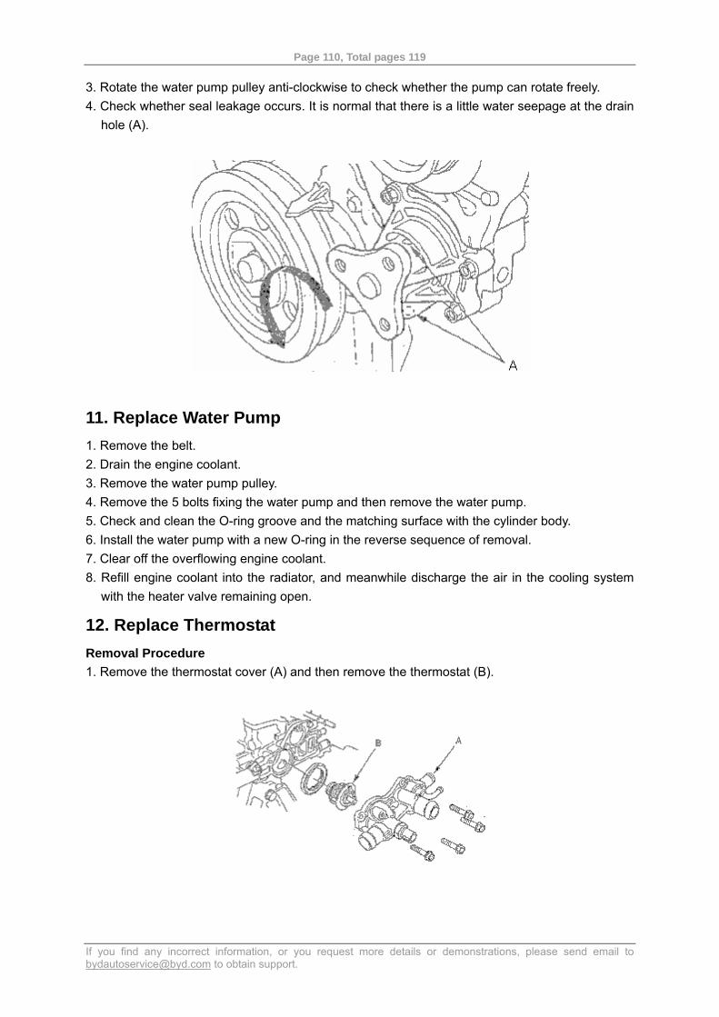
Page 110, Total pages 119
If you find any incorrect information, or you request more details or demonstrations, please send email to [email protected] to obtain support.
3. Rotate the water pump pulley anti-clockwise to check whether the pump can rotate freely. 4. Check whether seal leakage occurs. It is normal that there is a little water seepage at the drain
hole (A).
11. Replace Water Pump 1. Remove the belt. 2. Drain the engine coolant. 3. Remove the water pump pulley. 4. Remove the 5 bolts fixing the water pump and then remove the water pump. 5. Check and clean the O-ring groove and the matching surface with the cylinder body. 6. Install the water pump with a new O-ring in the reverse sequence of removal. 7. Clear off the overflowing engine coolant. 8. Refill engine coolant into the radiator, and meanwhile discharge the air in the cooling system
with the heater valve remaining open.
12. Replace Thermostat Removal Procedure 1. Remove the thermostat cover (A) and then remove the thermostat (B).
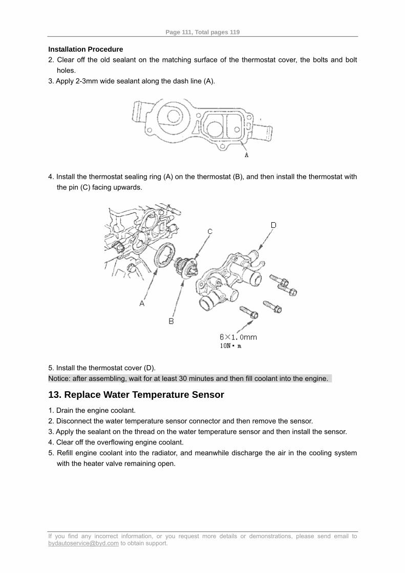
Page 111, Total pages 119
If you find any incorrect information, or you request more details or demonstrations, please send email to [email protected] to obtain support.
Installation Procedure 2. Clear off the old sealant on the matching surface of the thermostat cover, the bolts and bolt
holes. 3. Apply 2-3mm wide sealant along the dash line (A).
4. Install the thermostat sealing ring (A) on the thermostat (B), and then install the thermostat with the pin (C) facing upwards.
5. Install the thermostat cover (D). Notice: after assembling, wait for at least 30 minutes and then fill coolant into the engine.
13. Replace Water Temperature Sensor 1. Drain the engine coolant. 2. Disconnect the water temperature sensor connector and then remove the sensor. 3. Apply the sealant on the thread on the water temperature sensor and then install the sensor. 4. Clear off the overflowing engine coolant. 5. Refill engine coolant into the radiator, and meanwhile discharge the air in the cooling system
with the heater valve remaining open.
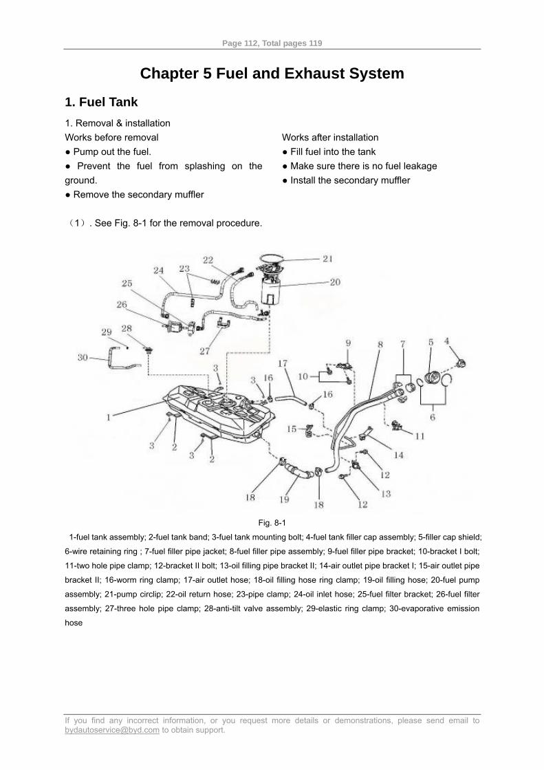
Page 112, Total pages 119
If you find any incorrect information, or you request more details or demonstrations, please send email to [email protected] to obtain support.
Chapter 5 Fuel and Exhaust System
1. Fuel Tank 1. Removal & installation Works before removal ● Pump out the fuel. ● Prevent the fuel from splashing on the ground. ● Remove the secondary muffler
Works after installation ● Fill fuel into the tank ● Make sure there is no fuel leakage ● Install the secondary muffler
(1). See Fig. 8-1 for the removal procedure.
Fig. 8-1
1-fuel tank assembly; 2-fuel tank band; 3-fuel tank mounting bolt; 4-fuel tank filler cap assembly; 5-filler cap shield;
6-wire retaining ring ; 7-fuel filler pipe jacket; 8-fuel filler pipe assembly; 9-fuel filler pipe bracket; 10-bracket I bolt;
11-two hole pipe clamp; 12-bracket II bolt; 13-oil filling pipe bracket II; 14-air outlet pipe bracket I; 15-air outlet pipe
bracket II; 16-worm ring clamp; 17-air outlet hose; 18-oil filling hose ring clamp; 19-oil filling hose; 20-fuel pump
assembly; 21-pump circlip; 22-oil return hose; 23-pipe clamp; 24-oil inlet hose; 25-fuel filter bracket; 26-fuel filter
assembly; 27-three hole pipe clamp; 28-anti-tilt valve assembly; 29-elastic ring clamp; 30-evaporative emission
hose
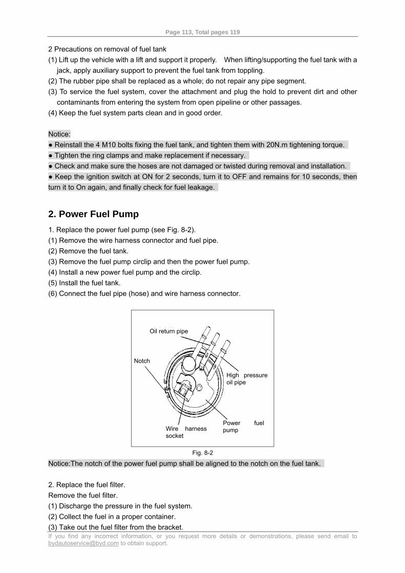
Page 113, Total pages 119
If you find any incorrect information, or you request more details or demonstrations, please send email to [email protected] to obtain support.
2 Precautions on removal of fuel tank (1) Lift up the vehicle with a lift and support it properly. When lifting/supporting the fuel tank with a
jack, apply auxiliary support to prevent the fuel tank from toppling. (2) The rubber pipe shall be replaced as a whole; do not repair any pipe segment. (3) To service the fuel system, cover the attachment and plug the hold to prevent dirt and other
contaminants from entering the system from open pipeline or other passages. (4) Keep the fuel system parts clean and in good order. Notice: ● Reinstall the 4 M10 bolts fixing the fuel tank, and tighten them with 20N.m tightening torque. ● Tighten the ring clamps and make replacement if necessary. ● Check and make sure the hoses are not damaged or twisted during removal and installation. ● Keep the ignition switch at ON for 2 seconds, turn it to OFF and remains for 10 seconds, then turn it to On again, and finally check for fuel leakage.
2. Power Fuel Pump 1. Replace the power fuel pump (see Fig. 8-2). (1) Remove the wire harness connector and fuel pipe. (2) Remove the fuel tank. (3) Remove the fuel pump circlip and then the power fuel pump. (4) Install a new power fuel pump and the circlip. (5) Install the fuel tank. (6) Connect the fuel pipe (hose) and wire harness connector.
Fig. 8-2
Notice:The notch of the power fuel pump shall be aligned to the notch on the fuel tank. 2. Replace the fuel filter. Remove the fuel filter. (1) Discharge the pressure in the fuel system. (2) Collect the fuel in a proper container. (3) Take out the fuel filter from the bracket.
Oil return pipe
Notch
High pressure oil pipe
Wire harness socket
Power fuel pump
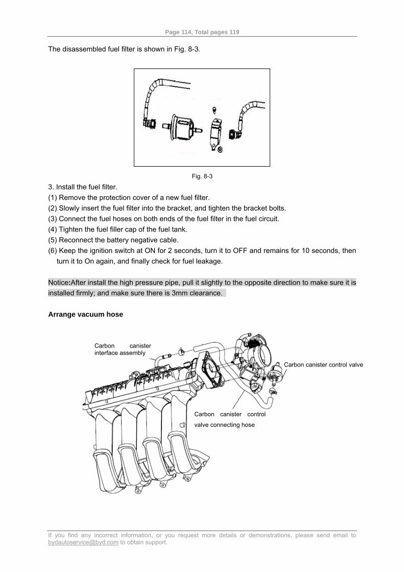
Page 114, Total pages 119
If you find any incorrect information, or you request more details or demonstrations, please send email to [email protected] to obtain support.
The disassembled fuel filter is shown in Fig. 8-3.
Fig. 8-3
3. Install the fuel filter. (1) Remove the protection cover of a new fuel filter. (2) Slowly insert the fuel filter into the bracket, and tighten the bracket bolts. (3) Connect the fuel hoses on both ends of the fuel filter in the fuel circuit. (4) Tighten the fuel filler cap of the fuel tank. (5) Reconnect the battery negative cable. (6) Keep the ignition switch at ON for 2 seconds, turn it to OFF and remains for 10 seconds, then
turn it to On again, and finally check for fuel leakage. Notice:After install the high pressure pipe, pull it slightly to the opposite direction to make sure it is installed firmly; and make sure there is 3mm clearance. Arrange vacuum hose
Carbon canister control valve
Carbon canister interface assembly
Carbon canister control
valve connecting hose
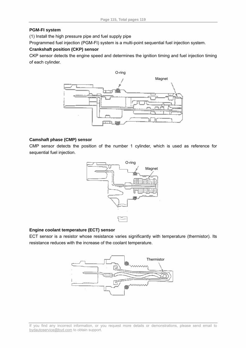
Page 115, Total pages 119
If you find any incorrect information, or you request more details or demonstrations, please send email to [email protected] to obtain support.
PGM-FI system (1) Install the high pressure pipe and fuel supply pipe Programmed fuel injection (PGM-FI) system is a multi-point sequential fuel injection system. Crankshaft position (CKP) sensor CKP sensor detects the engine speed and determines the ignition timing and fuel injection timing of each cylinder.
Camshaft phase (CMP) sensor CMP sensor detects the position of the number 1 cylinder, which is used as reference for sequential fuel injection.
Engine coolant temperature (ECT) sensor ECT sensor is a resistor whose resistance varies significantly with temperature (thermistor). Its resistance reduces with the increase of the coolant temperature.
Thermistor
Magnet O-ring
O-ring Magnet
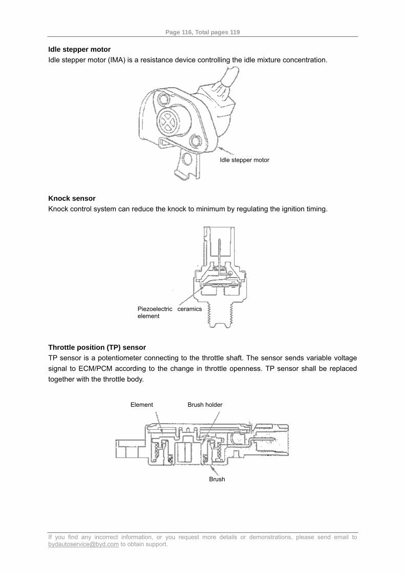
Page 116, Total pages 119
If you find any incorrect information, or you request more details or demonstrations, please send email to [email protected] to obtain support.
Idle stepper motor Idle stepper motor (IMA) is a resistance device controlling the idle mixture concentration.
Knock sensor Knock control system can reduce the knock to minimum by regulating the ignition timing.
Throttle position (TP) sensor TP sensor is a potentiometer connecting to the throttle shaft. The sensor sends variable voltage signal to ECM/PCM according to the change in throttle openness. TP sensor shall be replaced together with the throttle body.
Piezoelectric ceramicselement
Element Brush holder
Brush
Idle stepper motor
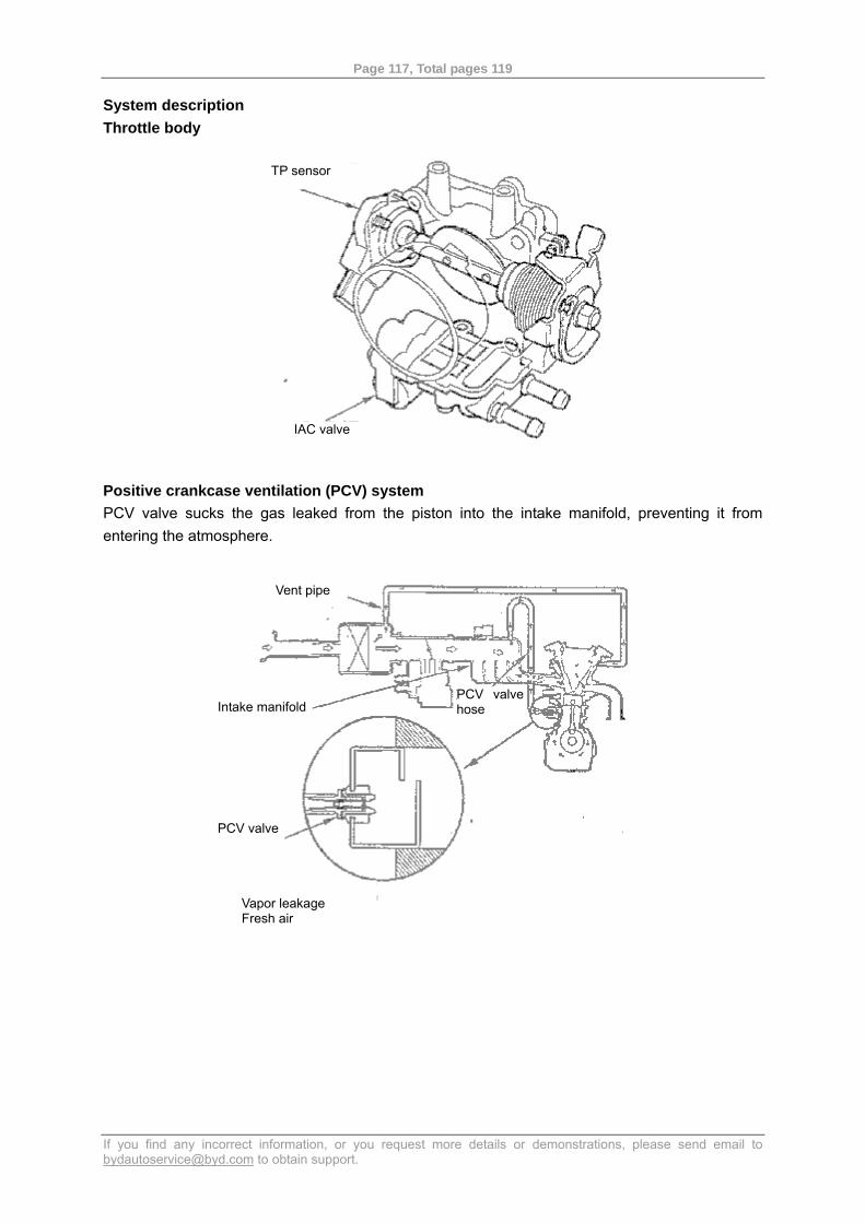
Page 117, Total pages 119
If you find any incorrect information, or you request more details or demonstrations, please send email to [email protected] to obtain support.
System description Throttle body
Positive crankcase ventilation (PCV) system PCV valve sucks the gas leaked from the piston into the intake manifold, preventing it from entering the atmosphere.
Vent pipe
Intake manifold PCV valve hose
PCV valve
Vapor leakage Fresh air
IAC valve
TP sensor
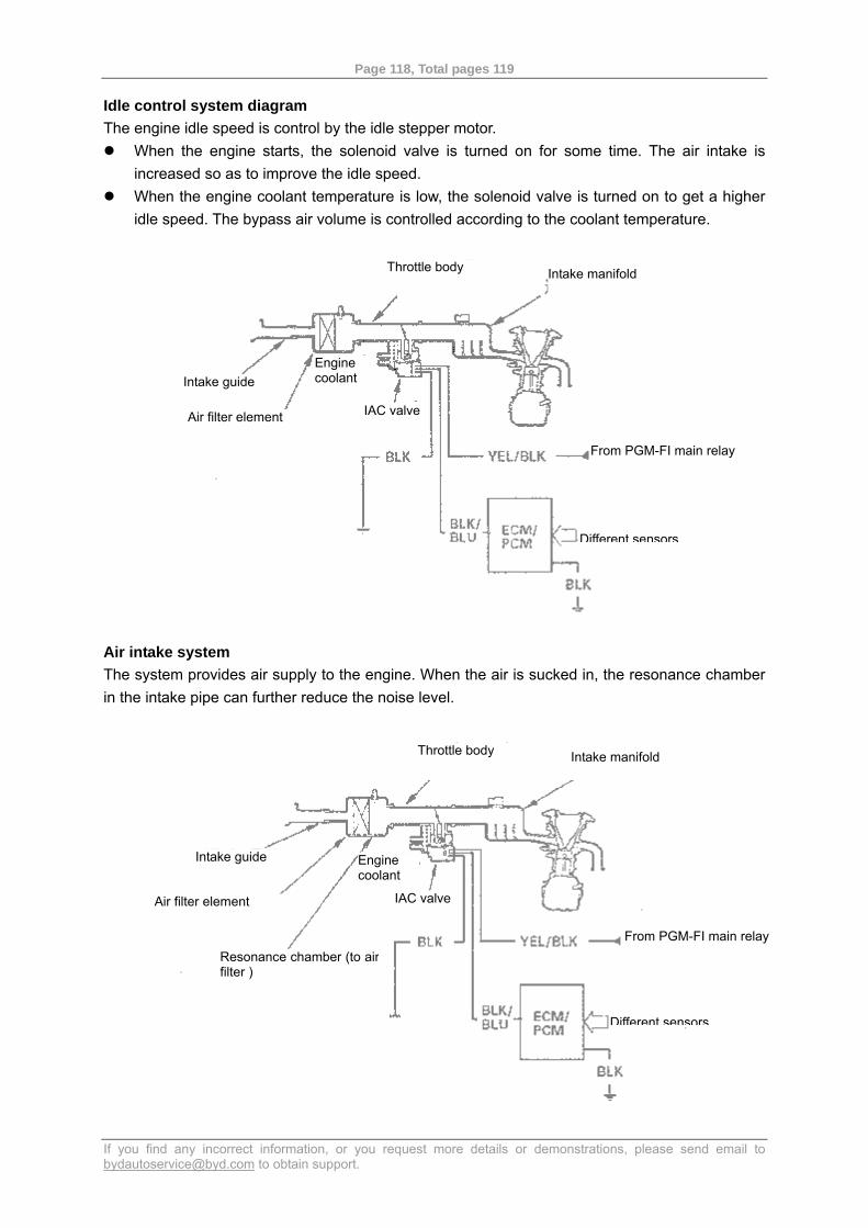
Page 118, Total pages 119
If you find any incorrect information, or you request more details or demonstrations, please send email to [email protected] to obtain support.
Idle control system diagram The engine idle speed is control by the idle stepper motor.
When the engine starts, the solenoid valve is turned on for some time. The air intake is increased so as to improve the idle speed.
When the engine coolant temperature is low, the solenoid valve is turned on to get a higher idle speed. The bypass air volume is controlled according to the coolant temperature.
Air intake system The system provides air supply to the engine. When the air is sucked in, the resonance chamber in the intake pipe can further reduce the noise level.
Air filter element
Throttle body
Intake guide Engine coolant
IAC valve
Intake manifold
Different sensors
Resonance chamber (to air filter )
From PGM-FI main relay
Throttle body Intake manifold
Intake guide
Air filter element
Engine coolant
IAC valve
From PGM-FI main relay
Different sensors
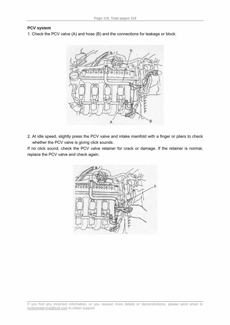
Page 119, Total pages 119
If you find any incorrect information, or you request more details or demonstrations, please send email to [email protected] to obtain support.
PCV system 1. Check the PCV valve (A) and hose (B) and the connections for leakage or block.
2. At idle speed, slightly press the PCV valve and intake manifold with a finger or pliers to check whether the PCV valve is giving click sounds.
If no click sound, check the PCV valve retainer for crack or damage. If the retainer is normal, replace the PCV valve and check again.