450 dual zone priority mixer -...
TRANSCRIPT
450
450 Dual Zone Priority Mixer
Use
rs G
uide

i
Table of Contents
450
Chapter 1 Introduction 1
Chapter 2 Operator Safety Summary 2
Chapter 3 Fast Setup 3
Chapter 4 Mic/Line Inputs 4
Chapter 5 Stereo Line Inputs 6
Chapter 6 Output Zone Master 7
Chapter 7 Priority Override Muting 9
Chapter 8 Applications 10
Chapter 9 Troubleshooting 12
Chapter 10 Specifications 13
Chapter 11 Warranty & Service 14
Appendix A Input/Output Connections 16
Appendix B Declaration of Conformity 17
Rev C.00, 6 July, 1999
Symetrix part number 53450-0C00
Subject to change without notice.
©1999, Symetrix, Inc. All right reserved.
Symetrix is a registered trademark of Symetrix, Inc.
Mention of third-party products is for informationalpurposes only and constitutes neither an endorsementnor a recommendation. Symetrix assumes noresponsibility with regard to the performance or useof these products.
Under copyright laws, no part of this manual may bereproduced or transmitted in any form or by anymeans, electronic or mechanical, including photo-copying, scanning, recording or by any informationstorage and retrieval system, without permission, inwriting, from Symetrix, Inc.
6408 216th St. SWMountlake Terrace, WA 98043 USA
Tel (425) 778-7728Fax (425) 778-7727
Email [email protected]
450
1
IntroductionChapter 1
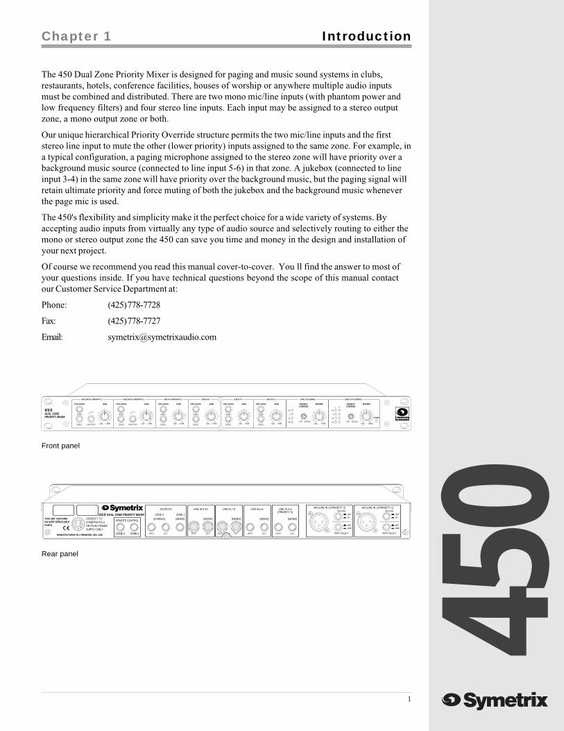
The 450 Dual Zone Priority Mixer is designed for paging and music sound systems in clubs,restaurants, hotels, conference facilities, houses of worship or anywhere multiple audio inputsmust be combined and distributed. There are two mono mic/line inputs (with phantom power andlow frequency filters) and four stereo line inputs. Each input may be assigned to a stereo outputzone, a mono output zone or both.
Our unique hierarchical Priority Override structure permits the two mic/line inputs and the firststereo line input to mute the other (lower priority) inputs assigned to the same zone. For example, ina typical configuration, a paging microphone assigned to the stereo zone will have priority over abackground music source (connected to line input 5-6) in that zone. A jukebox (connected to lineinput 3-4) in the same zone will have priority over the background music, but the paging signal willretain ultimate priority and force muting of both the jukebox and the background music wheneverthe page mic is used.
The 450's flexibility and simplicity make it the perfect choice for a wide variety of systems. Byaccepting audio inputs from virtually any type of audio source and selectively routing to either themono or stereo output zone the 450 can save you time and money in the design and installation ofyour next project.
Of course we recommend you read this manual cover-to-cover. You ll find the answer to most ofyour questions inside. If you have technical questions beyond the scope of this manual contactour Customer Service Department at:
Phone: (425) 778-7728
Fax: (425) 778-7727
Email: [email protected]
RIGHT LEFTRIGHT LEFTRIGHT LEFTRIGHT LEFT
MIC/LINE IN 2 (PRIORITY 2)
INOUT
MICLINE
MIC PAD
INPUT SELECT INPUT SELECT
LINEMIC
ZONE 1ZONE 2
SUPPLY ONLY.OR PS-3E POWERSYMETRIX PS-3CONNECT TO
PARTS.NO USER SERVICABLETHIS UNIT CONTAINS
MANUFACTURED IN LYNNWOOD, WA, USA
OUTIN
MIC PAD
(MONO)
(PRIORITY 3)LINE IN 3-4
(MONO)
LINE IN 5-6
RIGHT LEFT
(STEREO)
ZONE 2
REMOTE CONTROL
ZONE 1
(MONO)
LINE IN 9-10 MIC/LINE IN 1 (PRIORITY 1)
(MONO)
OUTPUTS
450 DUAL ZONE PRIORITY MIXER(MONO)
LINE IN 7-8
Front panel
Rear panel
OVERRIDEPRIORITY
ZONE 2 OUT (STEREO)ZONE 1 OUT (MONO)LINE IN 9-10LINE IN 7-8LINE IN 5-6LINE IN 3-4 (PRIORITY 3)MIC/LINE IN 2 (PRIORITY 2)MIC/LINE IN 1 (PRIORITY 1)
450DUAL ZONEPRIORITY MIXER
UUUUUUUU
+15dB+15dB+15dB+15dB+15dB+15dB+15dB+15dB ∞∞LOW BYPASS
MASTERMASTER
+15
0
-30
-15
+15
0
-15
-30
ZONE ASSIGNZONE ASSIGNZONE ASSIGNZONE ASSIGN
∞
GAIN
∞
GAIN
∞
GAIN
∞
GAIN
∞
GAINZONE ASSIGN
∞POWER
PRIORITYOVERRIDE
BYPASSLOW
ZONE 1
ZONE 2
ZONE 1
ZONE 2
ZONE 1
ZONE 2
ZONE 1
ZONE 2
ZONE 1
HIGH PASSZONE 2
RL
GAIN
HIGH PASSZONE 2
ZONE ASSIGN
ZONE 1
450
2
Operator Safety Summary Chapter 2
TermsSeveral notational conventions are used in thismanual. Some paragraphs may use Note, Caution,or Warning as a heading. Certain typefaces andcapitalization are used to identify certain words.These are:
Note Identifies information that needsextra emphasis. A Note generallysupplies extra information to helpyou to better use the 450.
Caution Identifies information that, if notheeded, may cause damage to the450 or other equipment in yoursystem.
Warning Identifies information that, ifignored, may be hazardous to yourhealth or that of others.
CAPITALS Controls, switches or other markingson the 450's chassis.
Boldface Strong emphasis.
Equipment Markings
AVIS: NE PAS OUVRIR
Il ne se trouve a l’interieur aucune piece pourvant entre reparée l’usager.
SEE OWNERS MANUAL. VOIR CAHIER D’INSTRUCTIONS.
S’adresser a un reparateur compétent.
RISQUE DE CHOC ELECTRIQUE
No user serviceable parts inside. Refer servicing to qualified service personnel.
CAUTION
WARNING:TO REDUCE THE RISK OF FIRE ORELECTRIC SHOCK DO NOT EXPOSETHIS EQUIPMENT TO RAIN OR MOISTURE
DO NOT OPENRISK OF ELECTRIC SHOCK
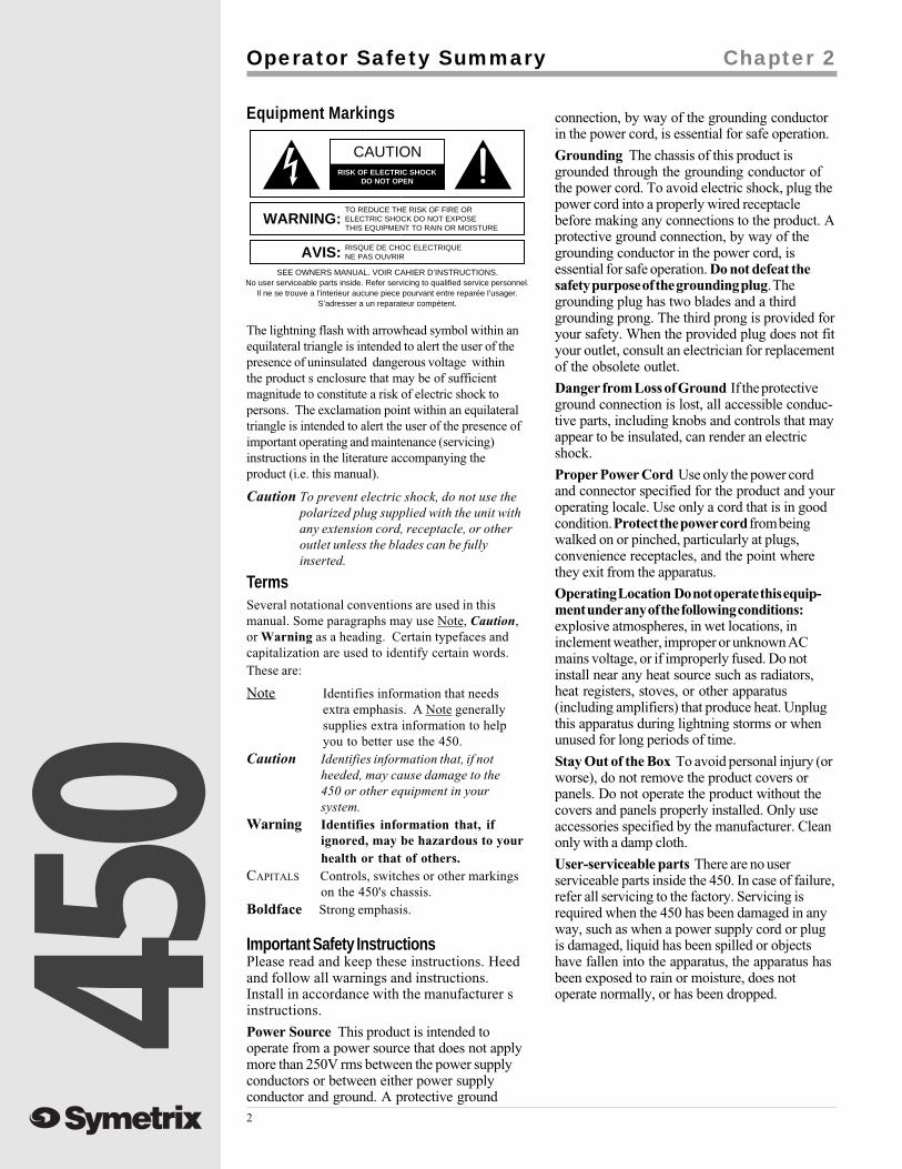
The lightning flash with arrowhead symbol within anequilateral triangle is intended to alert the user of thepresence of uninsulated dangerous voltage withinthe product s enclosure that may be of sufficientmagnitude to constitute a risk of electric shock topersons. The exclamation point within an equilateraltriangle is intended to alert the user of the presence ofimportant operating and maintenance (servicing)instructions in the literature accompanying theproduct (i.e. this manual).
Caution To prevent electric shock, do not use thepolarized plug supplied with the unit withany extension cord, receptacle, or otheroutlet unless the blades can be fullyinserted.
Important Safety InstructionsPlease read and keep these instructions. Heedand follow all warnings and instructions.Install in accordance with the manufacturer sinstructions.
Power Source This product is intended tooperate from a power source that does not applymore than 250V rms between the power supplyconductors or between either power supplyconductor and ground. A protective ground
connection, by way of the grounding conductorin the power cord, is essential for safe operation.
Grounding The chassis of this product isgrounded through the grounding conductor ofthe power cord. To avoid electric shock, plug thepower cord into a properly wired receptaclebefore making any connections to the product. Aprotective ground connection, by way of thegrounding conductor in the power cord, isessential for safe operation. Do not defeat thesafety purpose of the grounding plug. Thegrounding plug has two blades and a thirdgrounding prong. The third prong is provided foryour safety. When the provided plug does not fityour outlet, consult an electrician for replacementof the obsolete outlet.
Danger from Loss of Ground If the protectiveground connection is lost, all accessible conduc-tive parts, including knobs and controls that mayappear to be insulated, can render an electricshock.
Proper Power Cord Use only the power cordand connector specified for the product and youroperating locale. Use only a cord that is in goodcondition. Protect the power cord from beingwalked on or pinched, particularly at plugs,convenience receptacles, and the point wherethey exit from the apparatus.
Operating Location Do not operate this equip-ment under any of the following conditions:explosive atmospheres, in wet locations, ininclement weather, improper or unknown ACmains voltage, or if improperly fused. Do notinstall near any heat source such as radiators,heat registers, stoves, or other apparatus(including amplifiers) that produce heat. Unplugthis apparatus during lightning storms or whenunused for long periods of time.
Stay Out of the Box To avoid personal injury (orworse), do not remove the product covers orpanels. Do not operate the product without thecovers and panels properly installed. Only useaccessories specified by the manufacturer. Cleanonly with a damp cloth.
User-serviceable parts There are no userserviceable parts inside the 450. In case of failure,refer all servicing to the factory. Servicing isrequired when the 450 has been damaged in anyway, such as when a power supply cord or plugis damaged, liquid has been spilled or objectshave fallen into the apparatus, the apparatus hasbeen exposed to rain or moisture, does notoperate normally, or has been dropped.

450
3
1. Turn all front panel gain controls down.
2. Make sure all Zone Assign buttons areOUT.
3. Connect the 450 to AC power.
4. Set all back panel switches in correctposition. Take extra care to set the Mic/Line switch (found on Inputs 1 and 2only) in the appropriate position.
5. Connect all the audio inputs and outputsyou need.
6. Set BOTH Priority Override adjust-ments to BYPASS. To use this feature,see Priority Override Muting in theOperations section of this manual.
7. Assign the inputs to appropriate zones,set the Zone Out Master to 12:00 (unitygain), and turn up each input until thesound source is at the desired loudness.
8. Now read the rest of this manual.
Fast Setup
If you re in a hurry to get the 450 into your sound system and don t have time to thoroughly readthis manual, the following steps will probably be enough to get you started:
Chapter 3
450
4
Mic/Line Inputs
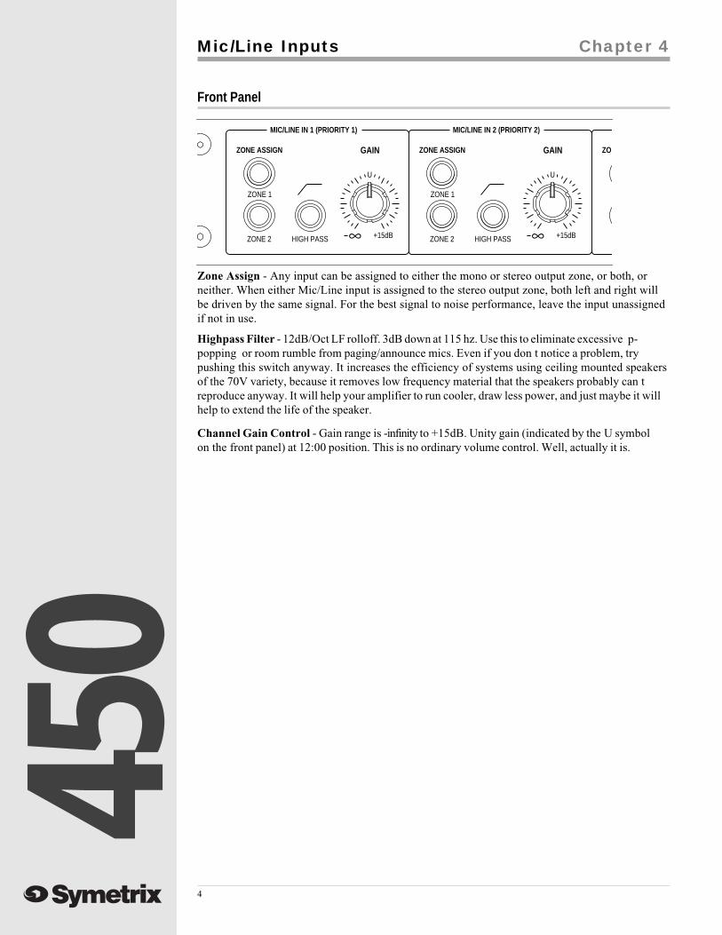
Front Panel
Zone Assign - Any input can be assigned to either the mono or stereo output zone, or both, orneither. When either Mic/Line input is assigned to the stereo output zone, both left and right willbe driven by the same signal. For the best signal to noise performance, leave the input unassignedif not in use.
Highpass Filter - 12dB/Oct LF rolloff. 3dB down at 115 hz. Use this to eliminate excessive p-popping or room rumble from paging/announce mics. Even if you don t notice a problem, trypushing this switch anyway. It increases the efficiency of systems using ceiling mounted speakersof the 70V variety, because it removes low frequency material that the speakers probably can treproduce anyway. It will help your amplifier to run cooler, draw less power, and just maybe it willhelp to extend the life of the speaker.
Channel Gain Control - Gain range is -infinity to +15dB. Unity gain (indicated by the U symbolon the front panel) at 12:00 position. This is no ordinary volume control. Well, actually it is.
Chapter 4
MIC/LINE IN 2 (PRIORITY 2)MIC/LINE IN 1 (PRIORITY 1)
UU
+15dB+15dB
ZO
∞
GAINZONE ASSIGN
∞
ZONE 1
HIGH PASSZONE 2
GAIN
HIGH PASSZONE 2
ZONE ASSIGN
ZONE 1

450
5
Rear Panel
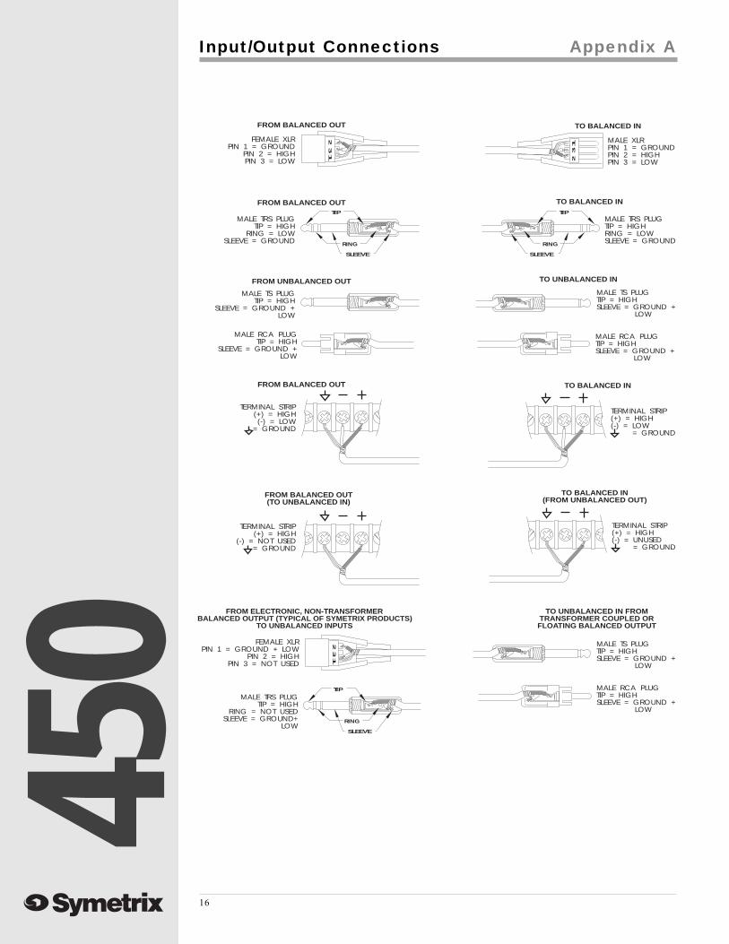
XLR Input Jack - In order to fit all the inputs and outputs onto the 450's rear panel, we combinedthe Mic/Line Input jacks into one balanced XLR connector that can handle both. This jack is wiredas follows:
Pin 1 = (ground, shield)
Pin 2 = (high, +)
Pin 3 = (low, -)
Most low impedance, balanced microphones (and many line level sources) can plug directly intothese jacks, but some sources will require adapters. See the chart in Appendix A for examples.
Caution Do not attempt to connect a high impedance, unbalanced micro- phone (theseusually, but not always, have a 1/4" phone jack attached to them) to either Mic/Lineinput unless you first disconnect the phantom power.
INPUT SELECT Switch - Push this switch in to accommodate line level sources such as PBXpaging outputs, mixing consoles, automated emergency announce systems, etc. This bypasses themic preamp circuit and disconnects phantom power from the XLR connector.
Note Make sure the Mic/Line input is not assigned to either Zone Output when you pushthe Mic/Line switch because the phantom power may cause a slight pop.
In the mic (out) position, the input signal is routed through the mic preamp and the phantom poweris engaged. The preamp stage delivers approximately 40 dB of gain.
Warning Do not put this switch into the Mic position when feeding a line level signal into thisinput (unless you enjoy re-coning speakers).
MIC PAD Switch - This decreases the gain of the mic preamp by 20 dB. Engage this switch if themic level signal source tends to overload the input preamp stage, or you notice that the incomingsignal is so hot that you have to run the Channel Gain knob really low. Typically, this happenswhen using high output condenser mics, or handheld, close-talked mics. As the name Mic Padsuggests, this switch does not affect the input gain when the channel is operating in Line mode.
Phantom Power- Phantom power is applied to the Mic/Line input only when the mic/line switch isin the mic (in) position. If you want to completely disconnect the phantom power, please contactSymetrix Customer Service.
MIC/LINE IN 2 (PRIORITY 2)
INOUT
MICLINE
MIC PAD
INPUT SELECT INPUT SELECT
LINEMIC
OUTIN
MIC PADMIC/LINE IN 1 (PRIORITY 1)

450
6
Rear Panel
Input Jacks - Line inputs 3-6 are equipped with 1/4", TRS (tip-ring-sleeve), balanced, phone jacks.They are wired as follows:
Tip = (high, +)
Ring = (low, -)
Sleeve = (ground, shield)
Line inputs 7-10 are unbalanced RCA-phono type jacks. They are wired as follows:
Tip = (high, +)
Sleeve = (ground, shield)
Though you ll be able to plug most line level outputs directly into the 450, some sources may needadapters. See Appendix A for proper wiring.
Mono/Stereo Operation - Line Inputs 3-10 are arranged in stereo pairs; each pair is assigned to asingle gain control on the front panel. If you want to use one of these inputs with a mono source,just insert a single plug into the jack labeled Left (mono) and leave the Right jack unconnected.The left jack will automatically feed both the left and right channels of the Zone 2 (stereo) output.
Stereo Line Inputs
Front Panel
Zone Assign - As you might expect, the Left and Right input signals are summed when fed to theZone 1 (mono) output. This is done independently of the Zone 2 (Stereo) feed, which keeps thesignals separate. As with the Mic/Line inputs, maximize the unit s signal-to-noise ratio by leavingall unused inputs unassigned.
Channel Gain - The wide gain range of this control (-infinity to +15dB) accommodates the variety ofinput levels generically known as line level , including tape decks, CD players, console feeds, etc.Unity gain is indicated by the u symbol on the front panel.
Chapter 5
LINE IN 9-10LINE IN 7-8LINE IN 5-6LINE IN 3-4 (PRIORITY 3)
UUUU
+15dB+15dB+15dB+15dB
+1
-1
-3
ZONE ASSIGNZONE ASSIGNZONE ASSIGNZONE ASSIGN
∞
GAIN
∞
GAIN
∞
GAIN
∞
GAIN
ZONE 1
ZONE 2
ZONE 1
ZONE 2
ZONE 1
ZONE 2
ZONE 1
ZONE 2
RIGHT LEFTRIGHT LEFTRIGHT LEFTRIGHT LEFT
E 1(MONO)
(PRIORITY 3)LINE IN 3-4
(MONO)
LINE IN 5-6
(MONO)
LINE IN 9-10
O) (MONO)
LINE IN 7-8

450
7
Output Zone Master
Output Jacks - The 450's outputs are electronically balanced, low-impedance, and capable ofdriving a balanced input to +22dBu. The output connectors are 1/4" Tip-Ring-Sleeve and you canfind wiring and adapter examples in Appendix A.
Master Gain Controls These controls have the same gain range as the input channel gain controls
-infinity to +15dB. The U symbol at the knob s 12:00 position indicates unity gain when the 450'soutput is driving a balanced input. The 450 uses a differential output driver that drops the outputlevel by 6db when connected to an unbalanced input. This does not adversely affect the audioquality whatsoever and is easily fixed by increasing the output gain knob setting by 6dB.
Chapter 6
Rear Panel
Front Panel
Remote Control - There are two ways to externally control the volume of the 450's Zone Outputs.Both options render the front panel master gain control inactive.
Option #1 - The easiest method is the old volume-knob-in-a-wall-plate. Use a 50k linear potentiom-eter and wire it as follows on the next page in diagrams 1 or 2.
The remote control cable is not carrying any audio signal, just DC control voltage. This means thatyou can use a very long cable (up to 1000’) without degrading the 450's performance whatsoever.To achieve this, you must use 20-22 gauge, three conductor plus ground cable and wire it accord-ing to diagram 2.
Option #2 - If you re using a programmable remote control system that has the ability to supply anexternal voltage to the 450, no problemo. Wire it as seen in Diagrams 3 or 4 on the following page.
The dB/Voltage gain scale is 5dB/V, Unity gain = 11.5V. Note that the +15V control voltagesupplied by the 450 (on the tip of the TRS connector) is not used in this configuration. This isokay, it won t hurt anything. In fact, you can save a little money on your remote cable by using oneconductor plus ground for short cable runs (see diagram 3) or two conductor plus ground for longruns (see diagram 4).
OVERRIDEPRIORITY
ZONE 2 OUT (STEREO)ZONE 1 OUT (MONO)
UU
+15dB+15dB ∞∞LOW BYPASS
MASTERMASTER
+15
0
-30
-15
+15
0
-15
-30
POWER
PRIORITYOVERRIDE
BYPASSLOW
RL
ZONE 1ZONE 2
RIGHT LEFT
(STEREO)
ZONE 2
REMOTE CONTROL
ZONE 1
(MONO)
OUTPUTS
AL ZONE PRIORITY MIXER

450
8
Diagram 2
RING
TIP
SLEEVE
FOR LONG DISTANCE ORNOISY ENVIRONMENTS
(OVER 100 FEET)
3 CONDUCTOR WITH SHIELD
SHIELD CONNECTEDAT PLUG END ONLY
OPTIONAL6K04 RESISTOR
50K LINEARPOTENTIOMETER
Diagram 3
Diagram 4
RING
TIP NOTCONNECTED
SLEEVE
SLEEVE TOGROUND
RING TO VOLTAGE SOURCE
RING
TIP NOTCONNECTED
SLEEVE
FOR LONG DISTANCE ORNOISY ENVIRONMENTS
(OVER 100 FEET)
2 CONDUCTOR WITH SHIELD
SLEEVE TOGROUND
RING TO VOLTAGE SOURCE
Diagram 1
RING
TIP
SLEEVE
OPTIONAL6K04 RESISTOR
50K LINEARPOTENTIOMETER
Remote Control Wiring
450
9
Priority Override Muting
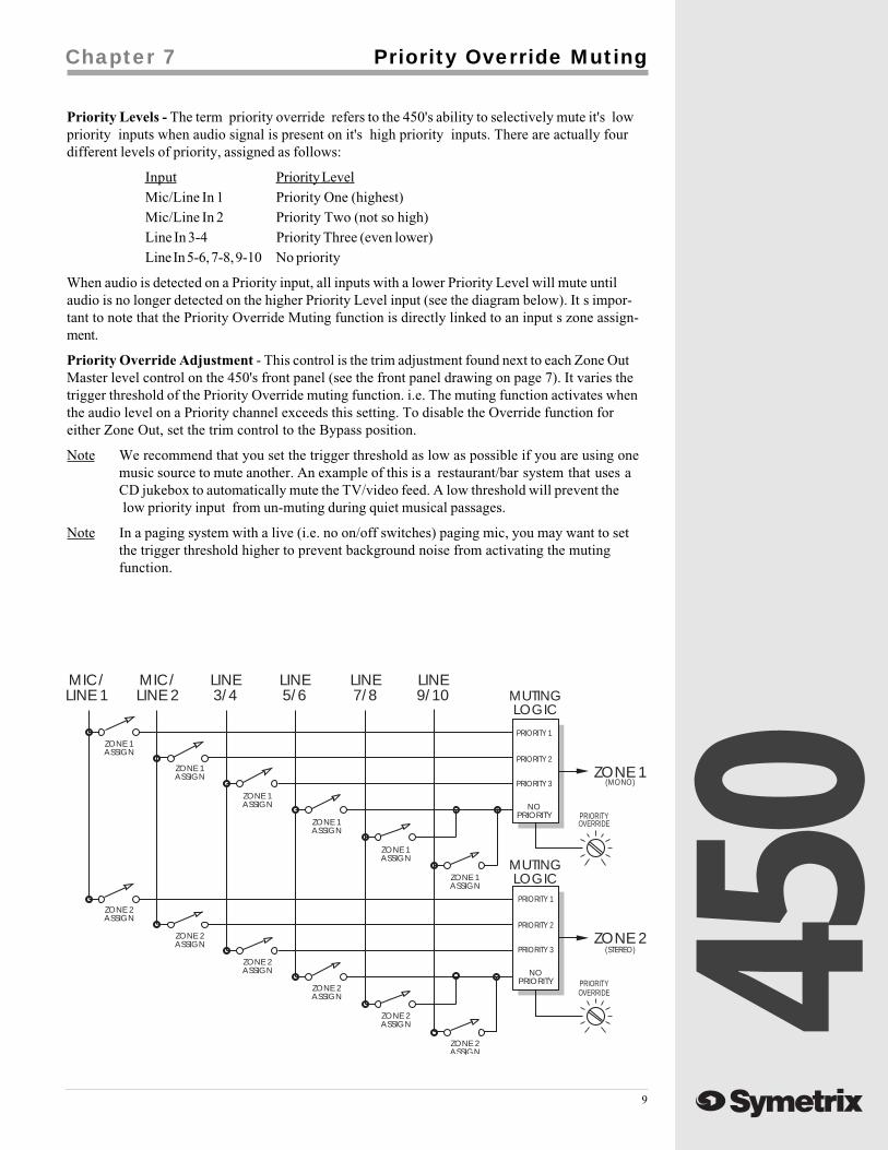
Priority Levels - The term priority override refers to the 450's ability to selectively mute it's lowpriority inputs when audio signal is present on it's high priority inputs. There are actually fourdifferent levels of priority, assigned as follows:
Input Priority LevelMic/Line In 1 Priority One (highest)Mic/Line In 2 Priority Two (not so high)Line In 3-4 Priority Three (even lower)Line In 5-6, 7-8, 9-10 No priority
When audio is detected on a Priority input, all inputs with a lower Priority Level will mute untilaudio is no longer detected on the higher Priority Level input (see the diagram below). It s impor-tant to note that the Priority Override Muting function is directly linked to an input s zone assign-ment.
Priority Override Adjustment - This control is the trim adjustment found next to each Zone OutMaster level control on the 450's front panel (see the front panel drawing on page 7). It varies thetrigger threshold of the Priority Override muting function. i.e. The muting function activates whenthe audio level on a Priority channel exceeds this setting. To disable the Override function foreither Zone Out, set the trim control to the Bypass position.
Note We recommend that you set the trigger threshold as low as possible if you are using onemusic source to mute another. An example of this is a restaurant/bar system that uses aCD jukebox to automatically mute the TV/video feed. A low threshold will prevent thelow priority input from un-muting during quiet musical passages.
Note In a paging system with a live (i.e. no on/off switches) paging mic, you may want to setthe trigger threshold higher to prevent background noise from activating the mutingfunction.
Chapter 7
ZONE 1
MIC/LINE 1
MIC/LINE 2
LINE3/4
LINE5/6
LINE7/8
LINE9/10
ZONE 2
MUTINGLOGIC
MUTINGLOGIC
PRIORITY 1
PRIORITY 1
(STEREO)
(MONO)
PRIORITY 2
PRIORITY 2
PRIORITY 3
PRIORITY 3
NOPRIORITY
ZONE 1ASSIGN
ZONE 2ASSIGN
ZONE 2ASSIGN
ZONE 2ASSIGN
ZONE 2ASSIGN
ZONE 2ASSIGN
ZONE 2ASSIGN
ZONE 1ASSIGN
ZONE 1ASSIGN
ZONE 1ASSIGN
ZONE 1ASSIGN
ZONE 1ASSIGN
NOPRIORITY
OVERRIDE
OVERRIDE
PRIORITY
PRIORITY
450
10
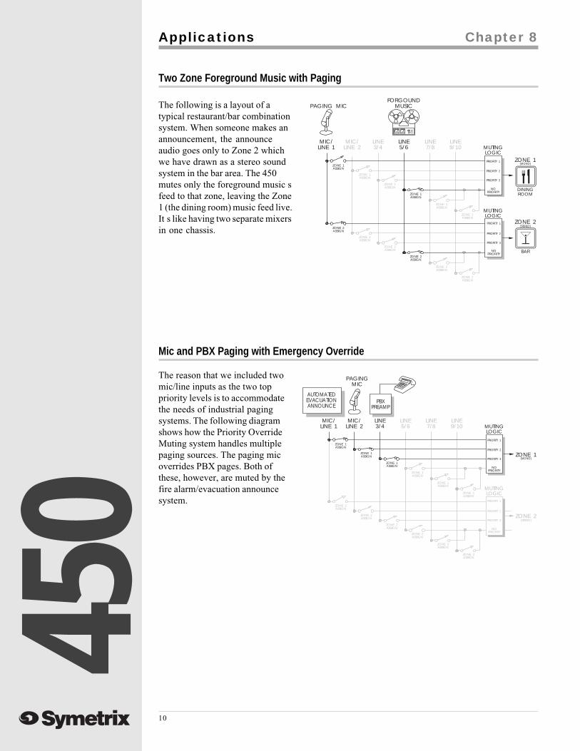
The following is a layout of atypical restaurant/bar combinationsystem. When someone makes anannouncement, the announceaudio goes only to Zone 2 whichwe have drawn as a stereo soundsystem in the bar area. The 450mutes only the foreground music sfeed to that zone, leaving the Zone1 (the dining room) music feed live.It s like having two separate mixersin one chassis.
Two Zone Foreground Music with Paging
ZONE 1
DININGROOM
MIC/LINE 1
PAGING MICFORGOUND
MUSIC
MIC/LINE 2
LINE3/4
LINE5/6
LINE7/8
LINE9/10
BAR
ZONE 2
MUTINGLOGIC
MUTINGLOGIC
PRIORITY 1
PRIORITY 1(STEREO)
(MONO)
PRIORITY 2
PRIORITY 2
PRIORITY 3
PRIORITY 3
NOPRIORITY
ZONE 1ASSIGN
ZONE 2ASSIGN
ZONE 2ASSIGN
ZONE 2ASSIGN
ZONE 2ASSIGN
ZONE 2ASSIGN
ZONE 2ASSIGN
ZONE 1ASSIGN
ZONE 1ASSIGN
ZONE 1ASSIGN
ZONE 1ASSIGN
ZONE 1ASSIGN
NOPRIORITY
Applications Chapter 8
Mic and PBX Paging with Emergency Override
ZONE 1
MIC/LINE 1
PAGINGMIC
MIC/LINE 2
LINE3/4
LINE5/6
LINE7/8
LINE9/10
ZONE 2
MUTINGLOGIC
MUTINGLOGIC
PRIORITY 1
PRIORITY 1
(STEREO)
(MONO)
PRIORITY 2
PRIORITY 2
PRIORITY 3
PRIORITY 3
NOPRIORITY
ZONE 1ASSIGN
ZONE 2ASSIGN
ZONE 2ASSIGN
ZONE 2ASSIGN
ZONE 2ASSIGN
ZONE 2ASSIGN
ZONE 2ASSIGN
ZONE 1ASSIGN
ZONE 1ASSIGN
ZONE 1ASSIGN
ZONE 1ASSIGN
ZONE 1ASSIGN
NOPRIORITY
PBXPREAMP
AUTOMATEDEVACUATIONANNOUNCE
The reason that we included twomic/line inputs as the two toppriority levels is to accommodatethe needs of industrial pagingsystems. The following diagramshows how the Priority OverrideMuting system handles multiplepaging sources. The paging micoverrides PBX pages. Both ofthese, however, are muted by thefire alarm/evacuation announcesystem.
450
11
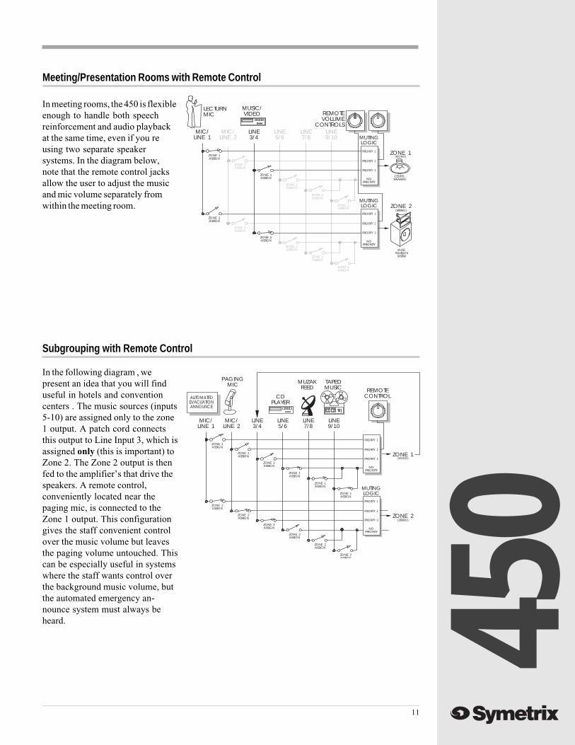
Meeting/Presentation Rooms with Remote Control
In meeting rooms, the 450 is flexibleenough to handle both speechreinforcement and audio playbackat the same time, even if you reusing two separate speakersystems. In the diagram below,note that the remote control jacksallow the user to adjust the musicand mic volume separately fromwithin the meeting room.
Subgrouping with Remote Control
TAPEDMUSIC REMOTE
CONTROL
ZONE 1
MIC/LINE 1
PAGINGMIC
MIC/LINE 2
LINE3/4
LINE5/6
LINE7/8
LINE9/10
ZONE 2
MUTINGLOGICPRIORITY 1
(STEREO)
(MONO)
PRIORITY 2
PRIORITY 3
ZONE 1ASSIGN
ZONE 2ASSIGN
ZONE 2ASSIGN
ZONE 2ASSIGN
ZONE 2ASSIGN
ZONE 2ASSIGN
ZONE 2ASSIGN
ZONE 1ASSIGN
ZONE 1ASSIGN
ZONE 1ASSIGN
ZONE 1ASSIGN
ZONE 1ASSIGN
NOPRIORITY
AUTOMATEDEVACUATIONANNOUNCE
PRIORITY 1
PRIORITY 3
NOPRIORITY
PRIORITY 2
CDPLAYER
MUZAKFEED
In the following diagram , wepresent an idea that you will finduseful in hotels and conventioncenters . The music sources (inputs5-10) are assigned only to the zone1 output. A patch cord connectsthis output to Line Input 3, which isassigned only (this is important) toZone 2. The Zone 2 output is thenfed to the amplifier’s that drive thespeakers. A remote control,conveniently located near thepaging mic, is connected to theZone 1 output. This configurationgives the staff convenient controlover the music volume but leavesthe paging volume untouched. Thiscan be especially useful in systemswhere the staff wants control overthe background music volume, butthe automated emergency an-nounce system must always beheard.
ZONE 1
MIC/LINE 1
LECTURNMIC
MUSIC/VIDEO REMOTE
VOLUMECONTROLS
MIC/LINE 2
LINE3/4
LINE5/6
LINE7/8
LINE9/10
ZONE 2
MUTINGLOGIC
MUTINGLOGIC
PRIORITY 1
PRIORITY 1(STEREO)
(MONO)
CEILINGSPEAKERS
MUSICPLAYBACK
SYSTEM
PRIORITY 2
PRIORITY 2
PRIORITY 3
PRIORITY 3
NOPRIORITY
ZONE 1ASSIGN
ZONE 2ASSIGN
ZONE 2ASSIGN
ZONE 2ASSIGN
ZONE 2ASSIGN
ZONE 2ASSIGN
ZONE 2ASSIGN
ZONE 1ASSIGN
ZONE 1ASSIGN
ZONE 1ASSIGN
ZONE 1ASSIGN
ZONE 1ASSIGN
NOPRIORITY

450
12
Troubleshooting Chapter 9
There is no output signal:
Check the AC power connections to the 450.
Check input and output cables and connections.
Determine that there really is a signal coming from the source and that it is getting to the 450.
Make sure that the input signal is assigned to Zone 1 or Zone 2 or both.
Distortion in the output signal:
Check the input signal. Is it overdriving the 450's input? If so, reduce the incoming signal levelor, in the case of microphone signals, use the 450's microphone pad.
Is the incoming signal already distorted? Listen up stream from the 450 to determine thatyou are feeding it a clean signal(s).
Buzz in the output:
Check input and output connector wiring.
Check for ground loops between interconnected system equipment.
Are all system components on the same AC ground?
Noise (hiss):
Check input signal levels and input level control settings. The input may be too low in level. Ifso, boost the incoming signal if possible. If the incoming signal is Mic level, make sure thatthe Mic/Line Switch for that input is set to Mic .
Is the input signal already noisy? Listen up stream from the 450 to determine that you arefeeding it a clean signal(s).
The 450 doesn’t power up or doesn’t respond properly:
Consult a qualified service technician or the Symetrix factory.
05413
Specifications
Specifications
Architects and Engineers Specifications
The audio microphone and line mixer shall be a high performance unit occupying a single rackspace (1U).
The unit shall have two low impedance, balanced microphone/line inputs with connection viafemale XLR. Each microphone/line input shall have a rear panel pushbutton which shall bypass themic preamp circuitry. Each input shall also have a switch to reduce the gain of the mic input by20dB. Associated with each microphone input shall also be a front panel level control potentiom-eter whose purpose is to establish the level of the microphone channel as it is mixed to either amono output zone, a stereo output zone, or both simultaneously. Each microphone input shall alsohave a first order low cut filter with a 115Hz rolloff frequency.
The mic/line mixer shall have four stereo, line level inputs. Each input shall be assignable to either amonaural output zone, a stereo output zone, or both. Associated with each line input shall be alevel control potentiometer whose purpose is to establish the level of the line level output signal asit is mixed to either a mono output zone, a stereo output zone, or both simultaneously.
The 450 shall incorporate a four level priority muting system as follows. High priority inputs shallmute or duck all lower priority inputs that are assigned to the same output zone when audio ispresent at the higher priority input. There shall be a threshold control in each zone master sectionwhich determines the minimum level of audio that will trigger the muting/ducking function. Priorityshall be assigned as follows: Mic/Line In 1 — Priority 1, Mic/Line In 2 — Priority 2, Line In 3-4 —Priority 3, Line In 5-6, 7-8, 9-10 — No Priority.
Independent master output level controls shall be provided for both the monaural output zone andthe stereo output zone. LED peak meters shall indicate the actual output level regardless of thenature of the load.
Independent means shall be provided to remotely control the output level of the mono output zoneand the stereo output zone. Rear panel jacks shall be provided to accept connections from standard50K linear potentiometers for this purpose. When wired for remote control, the front panel outputzone level controls shall be disabled.
The mic/line mixer shall be a Symetrix, Inc. model 450 Dual Zone Priority Mixer.
Chapter 10
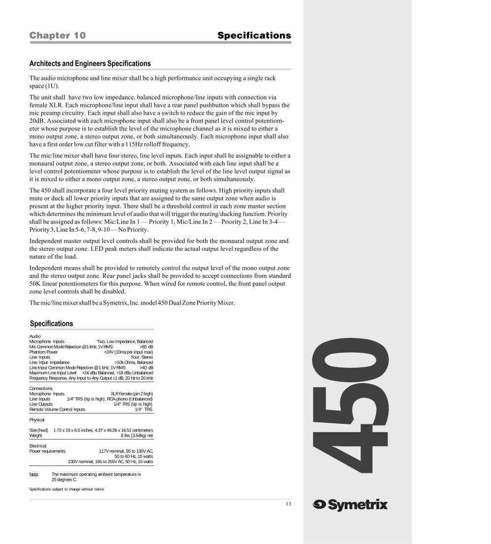
Note: The maximum operating ambient temperature is25 degrees C.
AudioMicrophone Inputs Two, Low Impedance, BalancedMic Common Mode Rejection @ 1 kHz, 1V RMS >85 dBPhantom Power +24V (10ma per input max)Line Inputs Four, StereoLine Input Impedance >10k Ohms, BalancedLine Input Common Mode Rejection @ 1 kHz, 1V RMS >40 dBMaximum Line Input Level +24 dBu Balanced, +18 dBu UnbalancedFrequency Response, Any Input to Any Output ±1 dB, 20 Hz to 20 kHz
ConnectionsMicrophone Inputs XLR Female (pin 2 high)Line Inputs 1/4" TRS (tip is high), RCA-phono (Unbalanced)Line Outputs 1/4" TRS (tip is high)Remote Volume Control Inputs 1/4" TRS
Physical
Size (hwd) 1.72 x 19 x 6.5 inches, 4.37 x 48.26 x 16.51 centimetersWeight 8 lbs (3.64kg) net
ElectricalPower requirements 117V nominal, 95 to 130V AC,
50 to 60 Hz, 15 watts230V nominal, 165 to 255V AC, 50 Hz, 15 watts
Specifications subject to change without notice.
450
14
Servicing the 450
Warranty & Service Chapter 11
450 Limited WarrantyWarranty
Following are the terms and limitations of the Symetrix warranty.
Symetrix, Inc. expressly warrants to the original purchaser ( Buyer ), subject to the terms and conditions set forthbelow, that the Product will be free from defects in material and workmanship as a result of normal commercial usefor eighteen (18) months from the date of shipment.
Some Symetrix products contain embedded software and may also be accompanied by control software intended tobe run on a personal computer. Said software is specifically excluded from this warranty.
Symetrix's warranty obligation is limited to the repair, replacement, or refund at Symetrix's sole discretion, of thepart or parts of the Product which may thus prove defective in materials or workmanship within one year from dateof purchase under normal use and which our examination discloses to our satisfaction to be thus defective,provided that Buyer gives Symetrix prompt notice of its warranty claim and satisfactory proof thereof.
Symetrix will make every reasonable effort to ensure that parts are available to support the repair of our productsunder warranty. In the event that a product or component part thereof becomes obsolete, unavailable or irreparable,Symetrix reserves the right to refund a prorated portion of the purchase price in full satisfaction of all warrantyclaims.
In order to serve you better we require that the Buyer shall, prior to shipping Product to Symetrix for warrantyservice, contact Symetrix and secure a Return Authorization Number that shall be included with the returnedProduct. This will facilitate our efforts to keep track of your Product and process your warranty repair as quickly aspossible. Buyer will prepay all freight charges to ship the Product to Symetrix for warranty inspection and service.This warranty is subject to Symetrix's inspection of the Product at its facilities and, upon Symetrix's request,satisfactory proof of purchase (dated copy of original retail dealer's invoice.)
Symetrix reserves the right to effect repairs to the product with reconditioned components/parts. Products oncerepaired under warranty will be shipped to Buyer freight prepaid by Symetrix via United Parcel Service (surface) orany similar shipper, to any location designated by buyer within the Continental United States. At Buyer's requestand expense Product will be returned via airfreight. Outside the continental United States, repaired or replacedproducts will be returned freight collect.
THIS WARRANTY IS EXPRESSLY IN LIEU OF ALL OTHER WARRANTIES EXPRESS OR IMPLIED, ARISINGBY LAW OR OTHERWISE (INCLUDING, WITHOUT LIMITATION ANY OBLIGATIONS OF THE SELLER WITHRESPECT TO CONSEQUENTIAL DAMAGES) INCLUDING THE WARRANTIES OF MERCHANTABILITY ANDFITNESS FOR USE AND OF ALL OTHER OBLIGATIONS OR LIABILITIES ON OUR PART, AND WE NEITHERASSUME, NOR AUTHORIZE ANY OTHER PERSON TO ASSUME FOR US, ANY OTHER LIABILITY IN CON-NECTION WITH THE SALE OF THE PRODUCT. THIS WARRANTY SHALL NOT APPLY TO THIS PRODUCTOR ANY PART THERE OF WHICH HAS BEEN SUBJECT TO ACCIDENT, NEGLIGENCE, ALTERATION,ABUSE, OR MISUSE. WE MAKE NO WARRANTY WHATSOEVER IN RESPECT TO ACCESSORIES OR PARTSNOT SUPPLIED BY US. THE TERM ORIGINAL PURCHASER, AS USED IN THIS WARRANTY SHALL BEDEEMED TO MEAN THAT PERSON OR COMPANY THAT ORIGINALLY PURCHASED THE PRODUCT.
This Symetrix product has been designed and manufactured for use in professional/industrial systems and is notintended for other usage. This warranty only applies to Buyers using the Product in professional/industrial systems.With respect to others, including but not limited to consumers for personal, family, or household use, Symetrixexpressly disclaims all warranties, including but not limited to warranties of merchantability and fitness for aparticular purpose and the express warranties as otherwise provided herein.
Symetrix reserves the right to modify the design or make additions to, or improvements to, its product lines withoutmaking similar upgrades to Product purchased by Buyer. Symetrix does not authorize any third party, including anydealer or sales representative, to assume any liability, effect any repairs or modifications to the Product, or makeany additional warranties or representation regarding the Product or Product information on behalf of Symetrix.
Symetrix's total liability on any claim, whether in contract, tort (including negligence) or otherwise arising out of,connected with, or resulting from the manufacture, sale, delivery, resale, repair, replacement or use of Product willnot exceed the purchase price of the Product or any part thereof which gives rise to the claim. In no event willSymetrix be liable for any incidental or consequential damages including but not limited to damage for lost revenue,cost of capital, claims of customers for service interruptions or failure to supply, and costs and expenses incurred inconnection with labor, overhead, transportation, installation or removal of products or substitute facilities or supplyhouses as a result of Product failure.
This limited warranty gives Buyer certain rights. Buyer may have additional rights under applicable law.

450
15
If you have determined that your 450 requires repair services and you live outside of theUnited States, please contact your local Symetrix dealer or distributor for instructions on howto obtain service. If you reside in the U.S. then proceed as follows:
Before sending anything to Symetrix, contact our Customer Service Department for a returnauthorization (RA) number. The telephone number is (425) 778-7728 or email:[email protected]
In-warranty Repairs
To get your 450 repaired under the terms of the warranty:
1. Call us for an RA number.
2. Pack the unit in its original packaging materials.
3. Include your name, address, daytime telephone number, and a briefstatement of the problem.
4. Write the RA number on the outside of the box.
5. Ship the unit to Symetrix, freight prepaid.
We do not accept freight collect shipments.
Repairs made in-warranty will cost you only one-way freight charges. We'll prepay the return(surface) freight.
If you send us your product in substandard packaging, we will charge you for factory shippingmaterials. If you don t have the factory packaging materials, please use an oversized carton,wrap the unit in a plastic bag, and surround it with bubble-wrap. Pack the box full ofStyrofoam peanuts. Be sure there is enough clearance in the carton to protect the rack ears(you wouldn't believe how many units are returned with bent ears). We will return the unit inSymetrix packaging. Of course, if the repair is due to operator error, parts and labor will becharged. In any event, if there are charges for the repair costs, you will pay for the returnfreight. All charges will be COD unless you have made other arrangements (prepaid, Visa orMastercard).
Out-of-warranty Repairs
If the warranty period has passed, you'll be billed for all necessary parts, labor, packagingmaterials, and freight charges. Please remember, you must call for an RA number beforesending the unit to Symetrix.
Servicing the 450
450
16
Input/Output Connections Appendix A
FROM BALANCED OUT(TO UNBALANCED IN)
FROM ELECTRONIC, NON-TRANSFORMERBALANCED OUTPUT (TYPICAL OF SYMETRIX PRODUCTS)
TO UNBALANCED INPUTS
FROM BALANCED OUT
FROM UNBALANCED OUT
FROM BALANCED OUT
FROM BALANCED OUT
FEMALE XLRPIN 1 = GROUND
PIN 2 = HIGHPIN 3 = LOW
MALE XLRPIN 1 = GROUNDPIN 2 = HIGHPIN 3 = LOW
MALE TS PLUGTIP = HIGHSLEEVE = GROUND +
LOW
MALE RCA PLUGTIP = HIGHSLEEVE = GROUND +
LOW
MALE TRS PLUGTIP = HIGHRING = LOWSLEEVE = GROUND
MALE TRS PLUGTIP = HIGH
RING = LOWSLEEVE = GROUND
MALE TRS PLUGTIP = HIGH
RING = NOT USEDSLEEVE = GROUND+
LOW
MALE TS PLUGTIP = HIGH
SLEEVE = GROUND +LOW
MALE RCA PLUGTIP = HIGH
SLEEVE = GROUND +LOW
MALE TS PLUGTIP = HIGHSLEEVE = GROUND +
LOW
MALE RCA PLUGTIP = HIGHSLEEVE = GROUND +
LOW
TERMINAL STRIP(+) = HIGH(-) = LOW
= GROUND
TERMINAL STRIP(+) = HIGH(-) = LOW
= GROUND
TERMINAL STRIP(+) = HIGH(-) = UNUSED
= GROUND
TERMINAL STRIP(+) = HIGH
(-) = NOT USED= GROUND
FEMALE XLRPIN 1 = GROUND + LOW
PIN 2 = HIGHPIN 3 = NOT USED
2
2
23
3
31
1
1
RINGRING
RING
SLEEVESLEEVE
SLEEVE
TO BALANCED IN
TO BALANCED IN
TO BALANCED IN(FROM UNBALANCED OUT)
TO UNBALANCED IN
TIPTIP
TIP
TO UNBALANCED IN FROMTRANSFORMER COUPLED ORFLOATING BALANCED OUTPUT
TO BALANCED IN

450
17
Declaration of ConformityAppendix B
Declaration of Conformity
We, Symetrix Incorporated, 6408 216th St. SW, Mountlake Terrace, Washington, USA,declare under our sole responsibility that the product:
450 Dual Zone Priority Mixer
to which this declaration relates, is in conformity with the following standards:
EN 60065Safety requirements for mains operated electronic and relatedapparatus for household and similar general use.
EN 50081-1Electromagnetic compatibility - Generic emission standardPart 1: Residential, commercial, and light industry.
EN 50082-1Electromagnetic compatibility - Generic immunity standardPart 1: Residential, commercial, and light industry.
The technical construction file is maintained at:
Symetrix, Inc.6408 216th St. SW
Mountlake Terrace, WA, 98043USA
The authorized representative located within the European Community is:
World Marketing AssociatesP.O. Box 100
St. Austell, Cornwall, PL26 6YU, U.K.
Date of issue: 1 November 1995
Place of issue:Mountlake Terrace, Washington, USA
Authorized signature:
Dane Butcher, President, Symetrix Incorporated.

450

450

450
22
Symetrix, Inc.6408 216th St. SW
Mountlake Terrace, WA, 98043USA
Tel: (425) 778-7728Fax: (425) 778-7727
Website: http://www.symetrixaudio.comEmail: [email protected]