40gbase-sr4 qsfp+ 850nm 150m mtp/mpo ... - fs fiberstore 6 40gbase-sr4 qsfp+ 850nm 150m mtp/mpo...
TRANSCRIPT

40GBASE-SR4 QSFP+ 850nm 150m MTP/MPO Transceiver for MMF
• 40GBASE-SR4 40G Ethernet
• Breakout to 4 x 10GBASE-SR Ethernet
• Proprietary interconnections
1www.fs.com
40GBASE-SR4 QSFP+ 850NM 150M MTP/MPO TRANSCEIVER FOR MMF
Application
• Four-channel full-duplex transceiver module
• Hot Pluggable QSFP+ form factor
• Maximum link length of 100m on OM3
Multimode Fiber (MMF) and 150m on OM4
MMF
Features
QSFP-SR4-40G
• Reliable VCSEL array technology
• Built-in digital diagnostic functions,
including optical power monitoring
• Commercial operating case
temperature range: 0°C to 70°C
• Single 1x12 MPO receptacle
• Unretimed XLPPI electrical interface
• Max power dissipation <1.2W

Description
Product Specifications
2www.fs.com
QSFP+ transceiver modules are designed for use in 40 Gigabit per second links over multimode fiber. They are compliant with the QSFP+
MSA and IEEE 802.3ba 40GBASE-SR4 and breakout to 4 10GBASE-SR. Digital diagnostics functions are available via an I2C interface,
including Tx and Rx power monitoring. The optical transceiver is compliant per the RoHS Directive 2011/65/EU.
I.General Specifications
40GBASE-SR4 QSFP+ 850NM 150M MTP/MPO TRANSCEIVER FOR MMF
Parameter Value Unit Notes
Module Form Factor QSFP+
Number of Lanes 4 Tx and 4 Rx
Maximum Aggregate Data
Rate 42.0 Gb/s
Maximum Data Rate per
Lane 10.5 Gb/sHigher bit rates may be supported.
Please contact FS.
Protocols SupportedTypical applications include
40G Ethernet, Infiniband QDR,
SATA/SAS3
This module is not retimed
Electrical Interface and
Pin-out 38-pin edge connector Pin-out as defined by the QSFP+ MSA2
Maximum Power
Consumption 1.2 WattsVaries with output voltage swing and pre-
emphasis settings
Management InterfaceSerial, I2C-based, 400 kHz
maximum frequencyAs defined by the QSFP+ MSA2
2www.fs.com
40GBASE-SR4 QSFP+ 850NM 150M MTP/MPO TRANSCEIVER FOR MMF
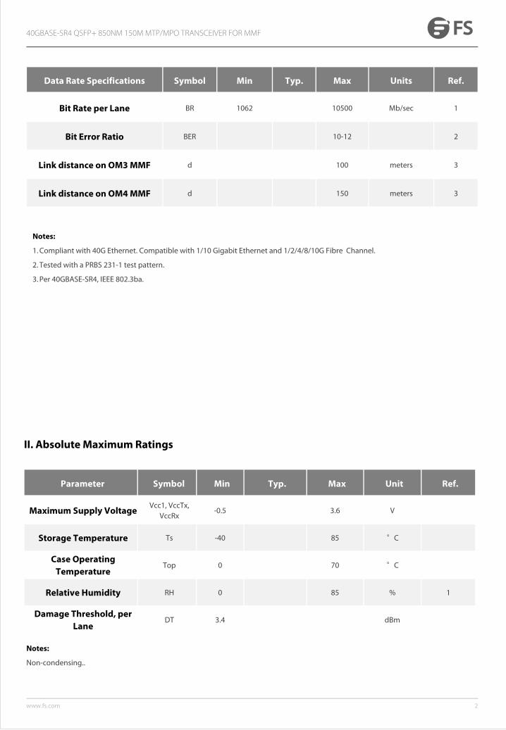
Data Rate Specifications Symbol Min Typ. Max Units Ref.
Bit Rate per Lane BR 1062 10500 Mb/sec 1
Bit Error Ratio BER 10-12 2
Link distance on OM3 MMF d 100 meters 3
Link distance on OM4 MMF d 150 meters 3
Notes:
1. Compliant with 40G Ethernet. Compatible with 1/10 Gigabit Ethernet and 1/2/4/8/10G Fibre Channel.
2. Tested with a PRBS 231-1 test pattern.
3. Per 40GBASE-SR4, IEEE 802.3ba.
II. Absolute Maximum Ratings
Notes:
Non-condensing..
Parameter Symbol Min Typ. Max Unit Ref.
Maximum Supply VoltageVcc1, VccTx,
VccRx-0.5 3.6 V
Storage Temperature Ts -40 85 °C
Case Operating Temperature
Top 0 70 °C
Relative Humidity RH 0 85 % 1
Damage Threshold, per Lane
DT 3.4 dBm

3www.fs.com
III. Electrical Characteristics (TOP= 0 to 70 °C, VCC = 3.14 to 3.46 Volts)
40GBASE-SR4 QSFP+ 850NM 150M MTP/MPO TRANSCEIVER FOR MMF
Parameter Symbol Min Typ. Max Unit Ref.
Supply VoltageVcc1,
VccTx, VccRx
3.15 3.45 V
Supply Current Icc 350 mA
Transmit turn-on time 2000 ms 2
Transmitter (per Lane)
Single ended input voltage tolerance
VinT -0.3 4.0 V
Differential data input swing Vin,pp 180 1200 mVpp 3
Differential input threshold 50 mV
AC common mode input voltage tolerance (RMS)
15 mV
Differential input return loss Per IEEE P802.3ba,Section 86A.4.1.1 dB 4
J2 Jitter Tolerance Jt2 0.17 UI
J9 Jitter Tolerance Jt9 0.29 UI
Data Dependent Pulse Width Shrinkage
DDPWS 0.07 UI
Eye mask colordinatesX1, X2 ,Y1, Y2
0.11, 0.31
95, 350UI
mV 5
Receiver (per Lane)
Single-ended output voltage -0.3 4.0 V
Differential data output swing Vout,pp 0 800 mVpp 6,7

4www.fs.com
Notes::
1. Maximum total power value is specified across the full temperature and voltage range.
2. 2From power-on and end of any fault conditions.
3. 3After internal AC coupling. Self-biasing 100Ω differential input.
4. 10 MHz to 11.1 GHz range
5. Hit ratio = 5 x 10E-5.
6. AC coupled with 100Ω differential output impedance.
7. Settable in 4 discrete steps via the I2C interface.
40GBASE-SR4 QSFP+ 850NM 150M MTP/MPO TRANSCEIVER FOR MMF
AC common mode output voltage (RMS)
7.5 mV
Termination mismatch at 1 MHx 5 %
Differential output return loss Per IEEE P802.3ba,Section 86A.4.2.1 dB 4
Common mode output return loss
Per IEEE P802.3ba,Section 86A.4.2.2 dB 4
Output transition time, 20% to 80%
28 ps
J2 Jitter output Jo2 0.42 UI
J9 Jitter output Jo9 0.65 UI
Eye mask coordinates #1X1, X2, Y1, Y2
0.29, 0.5 150, 425
UImV 5
Power Supply Ripple Tolerance PSR 50 mVpp

5www.fs.com
40GBASE-SR4 QSFP+ 850NM 150M MTP/MPO TRANSCEIVER FOR MMF
Relative Intensity Tolerance RIN -128 dB/H
Transmitter eye mask definition X1, X2, X3, Y1, Y2, Y3
(0.25, 0.4, 0.45, 0.25, 0.28, 0.4)
IV. Optical Characteristics (TOP = 0 to 70 , VCC = 3.14 to 3.46 V)
Parameter Symbol Min Typ. Max Unit Ref.
Transmitter (per Lane)
Signaling Speed per Lane 10.5 GBd 1
Center wavelengths 840 860 nm
RMS Spectral Width SW 0.65 nm
Average Launch Power per Lane
TXPx -7.6 -1.0 dBm
Transmit OMA per Lane TxOMA -5.6 3.0 dBm 2
Difference in Power between any two lanes (OMA)
DPx 4.0 dB
Peak Power per Lane PPx 4.0 dB
Launch Power (OMA) minus TDP per Lane
P-TDP -6.5 dBm
TDP per Lane TDP 3.5 dBm
Optical Extinction Ratio ER 3.0 dB
Optical Return Loss Tolerance ORL 12 dB
Encircled Flux FLX> 86% at 19 um< 30% at 4.5 um
dBm
Average launch power of OFF transmitter, per lane
-30 dBm

6www.fs.com
40GBASE-SR4 QSFP+ 850NM 150M MTP/MPO TRANSCEIVER FOR MMF
Receiver (per Lane)
Signaling Speed per Lane 10.5 GBd 3
Center wavelengths 840 860 nm
Damage Threshold DT 3.4 dBm
Receive Power (OMA) per Lane
RxOMA 3.0 dBm
Average Receive Power per Lane
RXPx 2.4 dBm
Stressed Receiver Sensitivity (OMA) per Lane
SRS -5.4 dBm
Peak Power, per lane PPx 4 dBm
Receiver Reflectance Rfl -12 dB
Vertical eye closure penalty, per lane
1.9 dB
Stressed eye J2 jitter, per Lane
0.3 UI
Stressed eye J9 jitter, per Lane
0.47 UI
OMA of each aggressor lane -0.4 dBm
Rx jitter tolerance:Jitter frequency and p-p
amplitude
(75, 5) kHz, UI
(375,1) kHz, UI
LOS De-Assert LOSD TBD dBm
LOS Assert LOSA TBD dBm
LOS Hysteresis 1 dB
Notes:
1.Transmitter consists of 4 lasers operating at a maximum rate of 10.5Gb/s each.
2.Even if TDP is <0.9dB, the OMA min must exceed this value.
3.Receiver consists of 4 photodetectors operating at a maximum rate of 10.5Gb/s each.
-11.1

8www.fs.com
40GBASE-SR4 QSFP+ 850NM 150M MTP/MPO TRANSCEIVER FOR MMF
Figure 1 – QSFP+ MSA-compliant 38-pin connector
Pin Symbol Name/Description Notes
1 GND Ground 1
2 Tx2n Transmitter Inverted Data Input
3 Tx2p Transmitter Non-Inverted Data Input
4 GND Ground 1
5 Tx4n Transmitter Inverted Data Input
6 Tx4p Transmitter Non-Inverted Data Input
7 GND Ground 1
8 ModSelL Module Select
9 ResetL Module Reset
V. Pin Description

9www.fs.com
40GBASE-SR4 QSFP+ 850NM 150M MTP/MPO TRANSCEIVER FOR MMF
10 Vcc Rx +3.3 V Power supply receiver
11 SCL 2-wire serial interface clock
12 SDA 2-wire serial interface data
13 GND Ground 1
14 Rx3p Receiver Non-Inverted Data Output
15 Rx3n Receiver Inverted Data Output
16 GND Ground 1
17 Rx1p Receiver Non-Inverted Data Output
18 Rx1n Receiver Inverted Data Output
19 GND Ground 1
20 GND Ground 1
21 Rx2n Receiver Inverted Data Output
22 Rx2p Receiver Non-Inverted Data Output
23 GND Ground 1
24 Rx4n Receiver Inverted Data Output
25 Rx4p Receiver Non-Inverted Data Output
26 GND Ground 1
27 ModPrsL Module Present
28 IntL Interrupt
29 Vcc Tx +3.3 V Power supply transmitter
30 Vcc1 +3.3 V Power Supply
31 LPMode Low Power Mode
32 GND Ground 1

10www.fs.com
40GBASE-SR4 QSFP+ 850NM 150M MTP/MPO TRANSCEIVER FOR MMF
34 Tx3n Transmitter Inverted Data Input
35 GND Ground 1
36 Tx1p Transmitter Non-Inverted Data Input
37 Tx1n Transmitter Inverted Data Input
38 GND Ground 1
Note:
Circuit ground is internally isolated from chassis ground.
VI. Mechanical Specifications

11www.fs.com
Test Center
FS.COM transceivers are tested to ensure connectivity and compatibility in our test center before shipped out. FS.COM test center is
supported by a variety of mainstream original brand switches and groups of professional staff, helping our customers make the most
efficient use of our products in their systems, network designs and deployments.
The original switches could be found nowhere but at FS.COM test center, eg: Juniper MX960 & EX 4300 series, Cisco Nexus 9396PX &
Cisco ASR 9000 Series, HP 5900 Series & HP 5406R ZL2 V3(J9996A), Arista 7050S-64, Brocade ICX7750-26Q & ICX6610-48, Avaya VSP 7000
MDA 2, etc.
Cisco ASR 9000 Series(A9K-MPA-1X40GE) ARISTA 7050S-64(DCS-7050S-64) Juniper MX960
Brocade ICX 7750-26Q Extreme Networks X670V VIM-40G4X Mellanox M3601Q
Dell N4032F HP 5406R ZL2 V3(J9996A) AVAYA 7024XLS(7002QQ-MDA)
40GBASE-SR4 QSFP+ 850NM 150M MTP/MPO TRANSCEIVER FOR MMF

12www.fs.com
Test Assured Program
FS.COM truly understands the value of compatibility and interoperability to each optics. Every module FS.COM provides must run
through programming and an extensive series of platform diagnostic tests to prove its performance and compatibility. In our test center,
we care of every detail from staff to facilities—professionally trained staff, advanced test facilities and comprehensive original-brand
switches, to ensure our customers to receive the optics with superior quality.
Our smart data system allows effective product management
and quality control according to the unique serial number,
properly tracking the order, shipment and every part.
Our in-house coding facility programs all of our parts to
standard OEM specs for compatibility on all major vendors and
systems such as Cisco, Juniper, Brocade, HP, Dell, Arista and so
on.
With a comprehensive line of original-brand switches, we can
recreate an environment and test each optics in practical
application to ensure quality and distance.
The last test assured step to ensure our products to be shipped
with perfect package.
40GBASE-SR4 QSFP+ 850NM 150M MTP/MPO TRANSCEIVER FOR MMF

13www.fs.com
Order Information
Part Number Description
QSFP-SR4-40G 40GBASE-SR4 QSFP+ 850nm 150m MTP/MPO Transceiver for MMF
QSFP-CSR4-40G 40GBASE-CSR4 QSFP+ 850nm 400m MTP/MPO Transceiver for MMF
QSFP-PIR4-40G 40GBASE-PLRL4 QSFP+ 1310nm 1.4km MTP/MPO Transceiver for SMF
QSFP-LX4-40G 40GBASE-UNIV QSFP+ 1310nm 2km LC Transceiver for SMF&MMF
QSFP-IR4-40G 40GBASE-LR4L QSFP+ 1310nm 2km LC Transceiver for SMF
QSFP-LR4-40G 40GBASE-LR4 and OTU3 QSFP+ 1310nm 10km LC Transceiver for SMF
QSFP-PLR4-40G 40GBASE-PLR4 QSFP+ 1310nm 10km MTP/MPO Transceiver for SMF
QSFP-ER4-40G 40GBASE-ER4 and OTU3 QSFP+ 1310nm 40km LC Transceiver for SMF
QSFP-BD-40G 40GBASE-SR Bi-Directional QSFP LC Duplex Transceiver for MMF
Notes:
40G QSFP+ transceiver module is individually tested on corresponding equipment such as Cisco, Arista, Juniper, Dell, Brocade and other
brands, and passes the monitoring of FS.COM intelligent quality control system.
40GBASE-SR4 QSFP+ 850NM 150M MTP/MPO TRANSCEIVER FOR MMF
