4. parking brake assembly (rear disc brake) - ken …. chassis/10. parking brake/04...parking brake...
TRANSCRIPT
PB-6
PARKING BRAKEPARKING BRAKE ASSEMBLY (REAR DISC BRAKE)
4. Parking Brake Assembly (Rear Disc Brake)
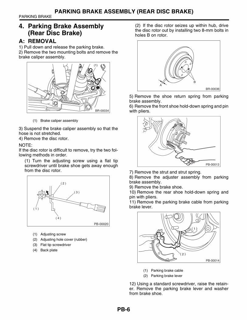
A: REMOVAL1) Pull down and release the parking brake.2) Remove the two mounting bolts and remove thebrake caliper assembly.
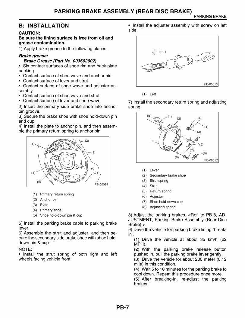
3) Suspend the brake caliper assembly so that thehose is not stretched.4) Remove the disc rotor.
NOTE:If the disc rotor is difficult to remove, try the two fol-lowing methods in order.
(1) Turn the adjusting screw using a flat tipscrewdriver until brake shoe gets away enoughfrom the disc rotor.
(2) If the disc rotor seizes up within hub, drivethe disc rotor out by installing two 8-mm bolts inholes B on rotor.
5) Remove the shoe return spring from parkingbrake assembly.6) Remove the front shoe hold-down spring and pinwith pliers.
7) Remove the strut and strut spring.8) Remove the adjuster assembly from parkingbrake assembly.9) Remove the brake shoe.10) Remove the rear shoe hold-down spring andpin with pliers.11) Remove the parking brake cable from parkingbrake lever.
12) Using a standard screwdriver, raise the retain-er. Remove the parking brake lever and washerfrom brake shoe.
(1) Brake caliper assembly
(1) Adjusting screw
(2) Adjusting hole cover (rubber)
(3) Flat tip screwdriver
(4) Back plate
(1)
BR-00034
PB-00020
( 1 )
( 2 )
( 3 )
( 4 )
(1) Parking brake cable
(2) Parking brake lever
AB
BR-00036
PB-00013
PB-00014
PB-7
PARKING BRAKEPARKING BRAKE ASSEMBLY (REAR DISC BRAKE)
B: INSTALLATIONCAUTION:Be sure the lining surface is free from oil and grease contamination. 1) Apply brake grease to the following places.
Brake grease:Brake Grease (Part No. 003602002)
• Six contact surfaces of shoe rim and back platepacking• Contact surface of shoe wave and anchor pin• Contact surface of lever and strut• Contact surface of shoe wave and adjuster as-sembly• Contact surface of shoe wave and strut• Contact surface of lever and shoe wave2) Insert the primary side brake shoe into anchorpin groove.3) Secure the brake shoe with shoe hold-down pinand cup.4) Install the plate to anchor pin, and then assem-ble the primary return spring to anchor pin.
5) Install the parking brake cable to parking brakelever.6) Assemble the strut and adjuster, and then se-cure the secondary side brake shoe with shoe hold-down pin & cup.
NOTE:• Install the strut spring of both right and leftwheels facing vehicle front.
• Install the adjuster assembly with screw on leftside.
7) Install the secondary return spring and adjustingspring.
8) Adjust the parking brakes. <Ref. to PB-8, AD-JUSTMENT, Parking Brake Assembly (Rear DiscBrake).>9) Drive the vehicle for parking brake lining “break-in”.
(1) Drive the vehicle at about 35 km/h (22MPH).(2) With the parking brake release buttonpushed in, pull the parking brake lever gently.(3) Drive the vehicle for about 200 meter (0.12mile) in this condition.(4) Wait 5 to 10 minutes for the parking brake tocool down. Repeat this procedure once more.(5) After breaking-in, re-adjust the parkingbrakes.
(1) Primary return spring
(2) Anchor pin
(3) Plate
(4) Primary shoe
(5) Shoe hold-down pin & cup
PB-00039
(1)
(4)
(5)
(2)
(3)
(1) Left
(1) Lever
(2) Secondary brake shoe
(3) Strut spring
(4) Strut
(5) Return spring
(6) Adjuster
(7) Shoe hold-down cup
(8) Adjusting spring
PB-00016
PB-00017
(1)(2)
(4)
(3)
(5)
(7)
(8)(6)
PB-8
PARKING BRAKEPARKING BRAKE ASSEMBLY (REAR DISC BRAKE)
C: INSPECTION1) Measure the brake disc rotor inside diameter. Ifthe disc is scored or worn, replace the brake discrotor.
Disc rotor inside diameter:Standard
Except STi model 170 mm (6.69 in)STi model 190 mm (7.48 in)
Service limitExcept STi model 171 mm (6.73 in)STi model 191 mm (7.52 in)
2) Measure the lining thickness. If it exceeds thelimit, replace the shoe assembly.
Lining thickness:Standard
3.2 mm (0.126 in)Service limit
1.5 mm (0.059 in)
NOTE:Replace the right and left brake shoes at the sametime.
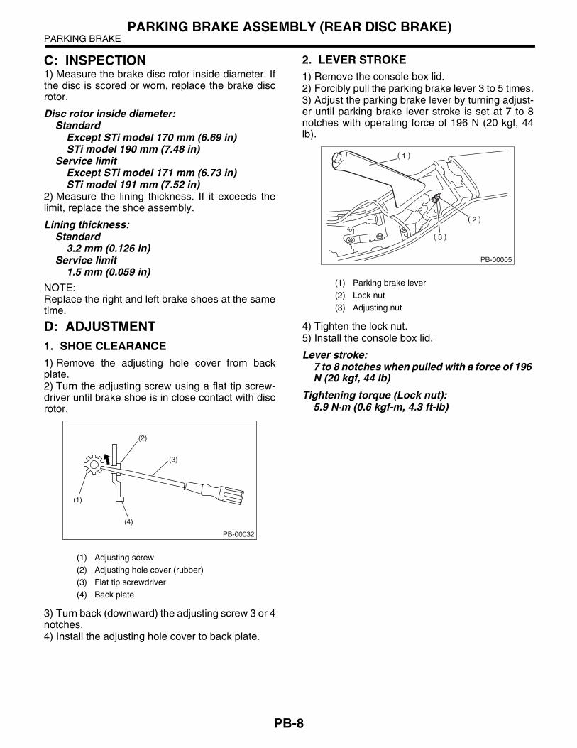
D: ADJUSTMENT1. SHOE CLEARANCE1) Remove the adjusting hole cover from backplate.2) Turn the adjusting screw using a flat tip screw-driver until brake shoe is in close contact with discrotor.
3) Turn back (downward) the adjusting screw 3 or 4notches.4) Install the adjusting hole cover to back plate.
2. LEVER STROKE1) Remove the console box lid.2) Forcibly pull the parking brake lever 3 to 5 times.3) Adjust the parking brake lever by turning adjust-er until parking brake lever stroke is set at 7 to 8notches with operating force of 196 N (20 kgf, 44lb).
4) Tighten the lock nut.5) Install the console box lid.
Lever stroke:7 to 8 notches when pulled with a force of 196 N (20 kgf, 44 lb)
Tightening torque (Lock nut):5.9 N·m (0.6 kgf-m, 4.3 ft-lb)
(1) Adjusting screw
(2) Adjusting hole cover (rubber)
(3) Flat tip screwdriver
(4) Back plate
(1)
(4)
(2)
(3)
PB-00032
(1) Parking brake lever
(2) Lock nut
(3) Adjusting nut
PB-00005