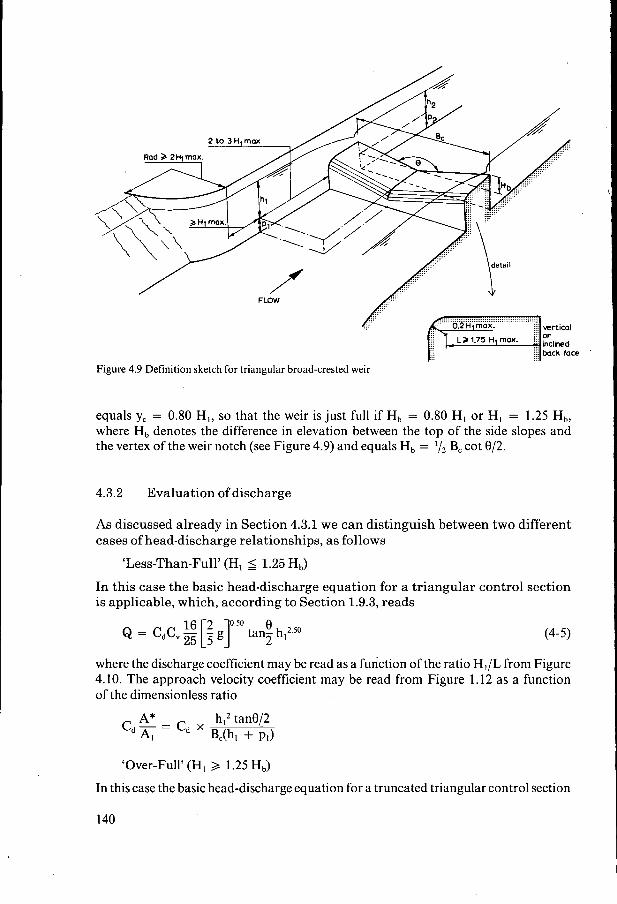
4 broad-crested weirs
TRANSCRIPT
Classified under the term 'broad-crested weirs' are those structures over which the streamlines run parallel to each other at least for a short distance, so that a hydrostatic pressure distribution may be assumed at the control section. To obtain this condition, the length in the direction of flow of the weir crest (L) is restricted to the total upstream energy head over the crest (HI). In the following sections the limitation on the ratio H,/L will be specified for the following types of broad-crested weirs: 4.1 Horizontal broad-crested weir; 4.2 The Romijn movable measuring/regulating weir; 4.3 Triangular broad-crested weir; 4.4 Broad-crested rectangular profile weir; 4.5 Faiyum weir. For details on other types of broad-crested weirs see Bos et al. (1984) and Bos (1985).
4 Broad-crested weirs
4.1 Horizontal broad-crested weir 4.1.1 Description
This weir is in use as a standard discharge measuring device and, as such, is described in the British Standard 3680, 1969, which is partly quoted below. The weir comprises a truly level and horizontal crest between vertical abutments. The upstream corner is rounded in such a manner that flow separation does not occur. Flow separation also can be avoided by using an upstream ramp which slopes between 2 - to - 1 and 3 - to - 1 (horz. to vert.). See Figure 1.34 for a longitudinal profile. This upstream sloping face is a cost-effective solution if the weir is constructed in concrete. Down- stream of the horizontal crest there may be a vertical face or a downward slope, de- pending on the submergence ratio under which the weir should operate at modular flow.
The weir structure should be rigid and watertight and be at right angles to the direc- tion of flow.
The dimensions of the weir and its abutments should comply with the requirements indicated in Figure.4.1. The minimum radius of the upstream rounded nose (r) is O. 1 1 HI,,,, although for the economic design of field structures a value r = 0.2 HI,,, is recommended. The length of the horizontal portion of the weir crest should not be less than 1.45 H,,,,. To obtain a favourable (high) discharge coefficient (cd) the crest length (L) should be close to the permissible minimum. In accordance with Section 2.2 the head measurement section should be located a distance of between two and three times HI,,, upstream of the weir block.
4.1.2 Evaluation of discharge
According to Equation 1-37 Section 1.9.1, the basic stage-discharge equation for a broad-crested weir with a rectangular throat reads
121
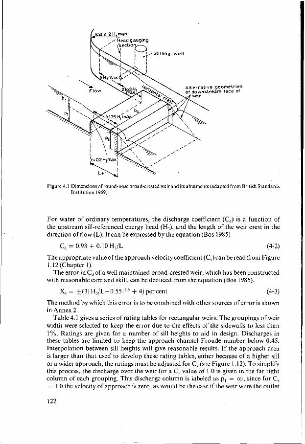
Figure 4.1 Dimensions of round-nose broad-crested weir and its abutments (adapted from British Standards Institution 1969)
For water of ordinary temperatures, the discharge coefficient (cd) is a function of the upstream sill-referenced energy head (HI), and the length of the weir crest in the direction of flow (L). It can be expressed by the equation (Bos 1985)
Cd = 0.93 + O.IOH,/L (4-2) The appropriate value of the approach velocity coefficient (C,) can be read from Figure 1.12 (Chapter 1).
The error in Cd of a well maintained broad-crested weir, which has been constructed with reasonable care and skill, can be deduced from the equation (Bos 1985).
X, = i- (3 I HJL- 0.55 1 + 4) per cent (4-3) The method by which this error is to be combined with other sources of error is shown in Annex 2.
Table 4.1 gives a series of rating tables for rectangular weirs. The groupings of weir width were selected to keep the error due to the effects of the sidewalls to less than 1%. Ratings are given for a number of sill heights to aid in design. Discharges in these tables are limited to keep the approach channel Froude number below 0.45. Interpolation between sill heights will give reasonable results. If the approach area is larger than that used to develop these rating tables, either because of a higher sill or a wider approach, the ratings must be adjusted for C, (see Figure 1.12). To simplify this process, the discharge over the weir for a C, value of 1 .O is given in the far right column of each grouping. This discharge column is labeled as pI = co, since for C, = 1.0 the velocity of approach is zero, as would be the case if the weir were the outlet
122
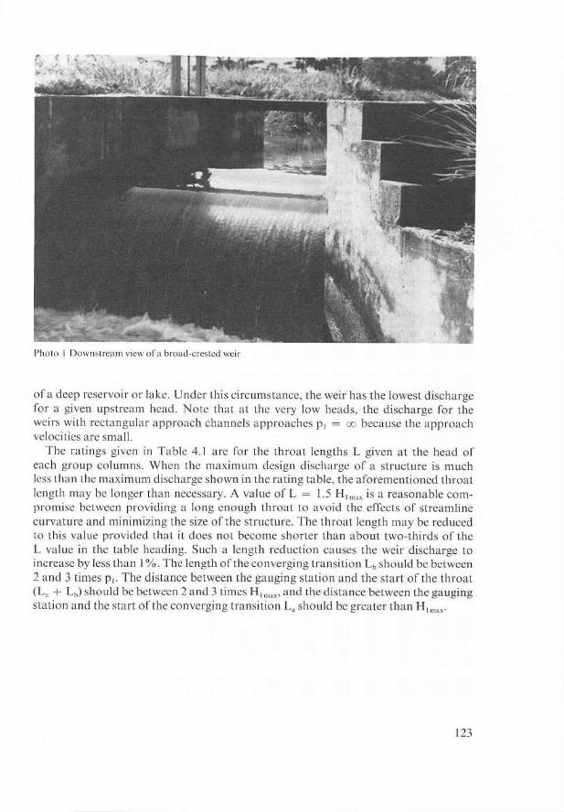
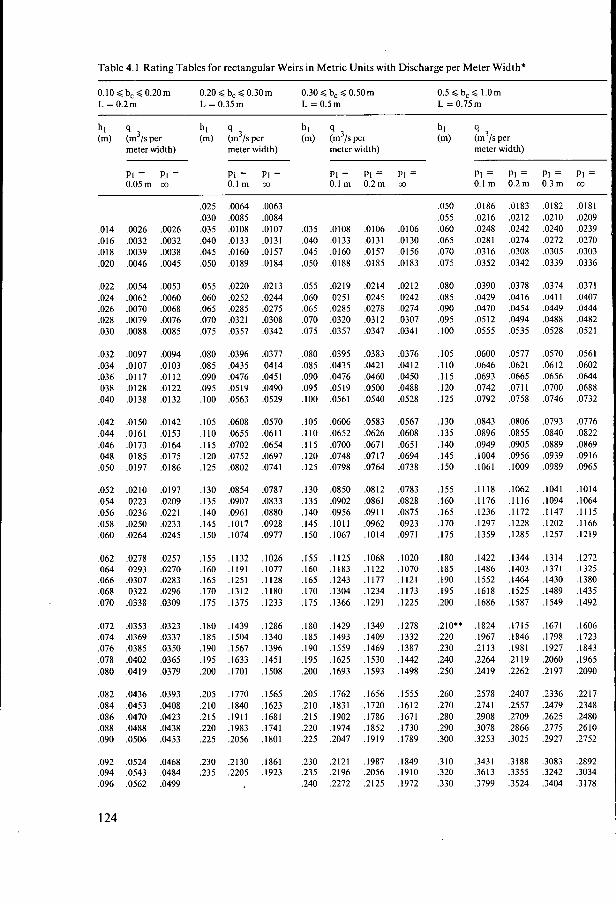
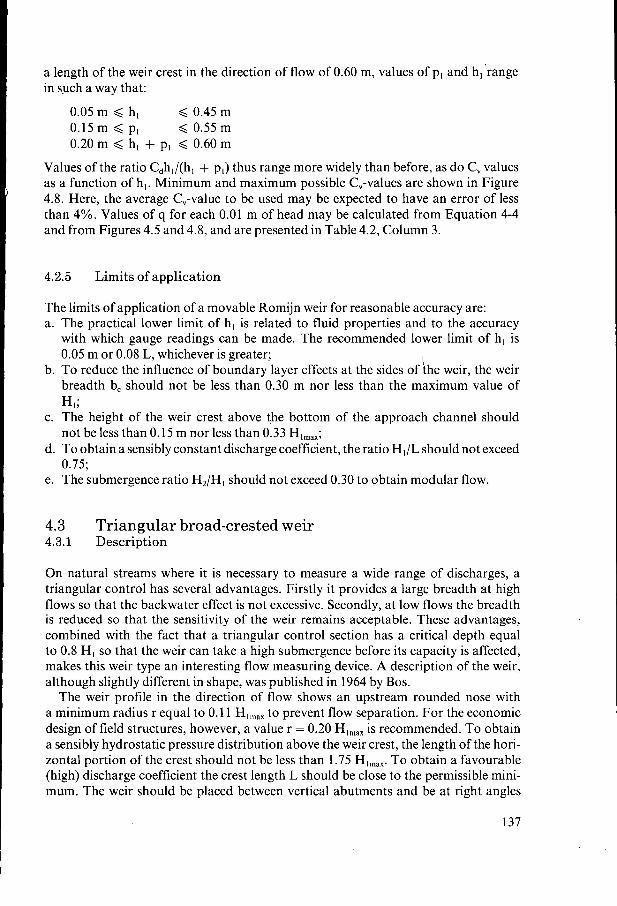
Table 4.1 Rating Tables for rectangular Weirs in Metric Units with Discharge per Meter Width*
0.10 < b, 40 .20m L = O.2m L = 0.35 m L = 0.5m L = 0.75m
0.20 < b, <0.30m 0.30 4 b, < 0.50m 0.5 < b, < 1.0m
hl q hl q hl q hl q (m) (m3/spe* (m) (m3/sper (m) (m3/sper (m) (m3/sper
meter width) meter width) meter width) meter width)
PI = PI = PI = PI = PI = PI = PI = PI = PI = PI = PI = 0.05m m 0.1 m m O.lm 0.2m m 0.1 m 0.2m 0.3 m 00
.O14 ,0026 ,0026 ,016 ,0032 .O032 .O18 ,0039 .O038 .O20 ,0046 ,0045
.O22 ,0054 .O053
.O24 .O062 .O060
.O26 ,0070 .O068
.O28 .O079 .O076
.O30 .O088 .O085
.O32 ,0097 ,0094
.O34 .O107 .O103
.O36 ,0117 ,0112
.O38 .O128 .O122
.O40 .O138 .O132
.O42 .O150 ,0142
.O44 .O161 .O153
.O46 ,0173 . O 1 6 4
.O48 .O185 .O175
.O50 .O197 .O186
.O52 ,0210 ,0197
.O54 ,0223 ,0209
.O56 .O236 ,0221 ,058 ,0250 ,0233 .O60 .O264 .O245
.O62 ,0278 ,0257
.O64 .O293 ,0270
.O66 .O307 ,0283
.O68 .O322 ,0296 ,070 ,0338 ,0309
.O72 .O353 ,0323
.O74 ,0369 ,0337
.O76 ,0385 ,0350
.O78 .O402 ,0365
.O80 ,0419 ,0379
.O82 ,0436 ,0393
.O84 ,0453 .O408
.O86 ,0470 .O423
.O88 ,0488 .O438
.O90 ,0506 .O453
.O92 .O524 .O468
.O94 ,0543 .O484
.O96 ,0562 ,0499
,025 .O064 .O063 ,030 ,0085 .O084 .O35 .O108 ,0107 .O40 ,0133 .O131 .O45 .O160 ,0157 ,050 .O189 ,0184
,055 ,0220 .O213 .O60 ,0252 .O244 .O65 .O285 .O275 .O70 .O321 ,0308 .O75 ,0357 .O342
.O80 ,0396 .O377
.O85 .O435 .O414 ,090 ,0476 .O451 .O95 ,0519 .O490 .IO0 ,0563 ,0529
.IO5 ,0608 .O570
.I10 ,0655 ,0611
.I15 .O702 ,0654 ,120 .O752 ,0697 ,125 .O802 ,0741
,130 ,0854 .O787 ,135 .O907 ,0833 ,140 ,0961 .O880 .I45 ,1017 ,0928 .I50 ,1074 ,0977
,155 ,1132 ,1026 .I60 ,1191 ,1077 .I65 ,1251 .I128 .I70 ,1312 ,1180 ,175 ,1375 .I233
.I80 ,1439 ,1286 ,185 ,1504 ,1340 ,190 ,1567 .I396 .I95 ,1633 ,1451 ,200 ,1701 ,1508
,205 ,1770 .I565 ,210 ,1840 .I623 ,215 .I911 ,1681 ,220 ,1983 .I741 ,225 .2056 ,1801
,230 ,2130 .I861 ,235 ,2205 .I923
.O35
.O40
.O45
.O50
.O55
.O60
.O65
.O70
.O75
.O80
.O85
.O90
.O95
.IO0
.IO5
.I10
.I15
.I20
.I25
,130 .I35 ,140 .I45 . I50
,155 . I60 ,165 ,170 ,175
.I80 ,185 .I90 .I95 ,200
.205
.210
.215 220 .225
230 235 ,240
.o IO8
.O133
.O160 ,0188
.O2 19 ,0251 .O285 .O320 ,0357
,0395 .O435 ,0476 .O519 ,0561
,0606 ,0652 .O700 .O748 ,0798
,0850 .O902 ,0956 .IO11 . I067
, I 125 ,1183 ,1243 .I304 ,1366
.I429
. I493
.I559
.I625 ,1693
,1762 ,1831 . I902 .I974 ,2047
,2121 ,2196 ,2272
,0106 ,0131 ,0157 ,0185
,0214 ,0245 ,0278 .O3 I 2 ,0347
,0383 ,0421 .O460 ,0500 ,0540
,0583 ,0626 ,0671 ,0717 ,0764
,0812 ,0861 .O91 I ,0962 ,1014
.I068
.I122 ,1177 .I234 ,1291
. I349
. I409
.I469
. I530
. I593
. I656
. I720
. I786
. I852 ,1919
,1987 ,2056 ,2125
.O106 ,0130 .O156 .O183
.o212
.O242 ,0274 ,0307 ,0341
.O376
.O4 1 2
.O450 ,0488 ,0528
,0567 ,0608 .O65 I ,0694 ,0738
.O783 ,0828 .O875 ,0923 ,0971
,1020 . I070 . I 121 ,1173 ,1225
. I278 ,1332 ,1387 .I442 . I498
,1555 .I612 .I671 ,1730 .I789
. I849 ,1910 . I972
.O50
.O55 ,060 .O65 ,070 .O75
.O80
.O85
.O90
.O95 ,100
.IO5 ,110 .I15 .I20 .I25
.I30
.I35 ,140 .I45 .I50
,155 .I60 .I65 .I70 .I75
.I80
.185
.I90 ,195 ,200
.210** 220 ,230 ,240 ,250
.260
.270 ,280 ,290 ,300
.310
.320
.330
.O186
.O2 16
.O248
.O28 I
.O3 16 ,0352
,0390 ,0429 ,0470 .o5 I2 ,0555
,0600 .O646 ,0693 .O742 ,0792
.O843
.O896 ,0949 . I004 ,1061
. I I18 ,1176 ,1236 ,1297 ,1359
,1422 .I486 .I552 ,1618 .I686
,1824 .I967 .21 I3 ,2264 .2419
.2578
.2741 ,2908 ,3078 ,3253
,3431 ,3613 .3799
,0183 ,0212 ,0242 ,0274 ,0308 .O342
,0378 ,0416 .O454 .O494 .O535
,0577 .O621 .O665 .O71 1 .O758
.O806 ,0855 .O905 .O956 .I009
.I062
.I116
.I172
.I228 ,1285
. I344
. I403 ,1464 . I525 . I587
,1715 . I846 ,1981 .21 I9 ,2262
,2407 .2557 .2709 2866 ,3025
.3 188
.3355 ,3524
,0182 .o2 I o .O240 ,0272 .O305 .O339
,0374 .O41 1 ,0449 ,0488 ,0528
,0570 .O6 I2 ,0656 ,0700 ,0746
,0793 ,0840 ,0889 ,0939 ,0989
.IO41
. I094 ,1147 . I202 . I257
,1314 ,1371 .I430 ,1489 .I549
.I671 ,1798 .I927 ,2060 2197
.2336 2479 ,2625 ,2775 ,2927
,3083 ,3242 ,3404
,0181 ,0209 .0239 ,0270 ,0303 ,0336
,0371 ,0407 ,0444 ,0482 ,0521
.0561
.0602
.0644 ,0688 ,0732
,0776 ,0822 ,0869 .O9 I6 ,0965
,1014 ,1064 . I I I5 ,1166 .1219
. I272 ,1325 ,1380 ,1435 ,1492
. I606
. I723
. I843 ,1965 .2090
,2217 ,2348 ,2480 ,2610 ,2752
.2892
.3034
.3 178
124
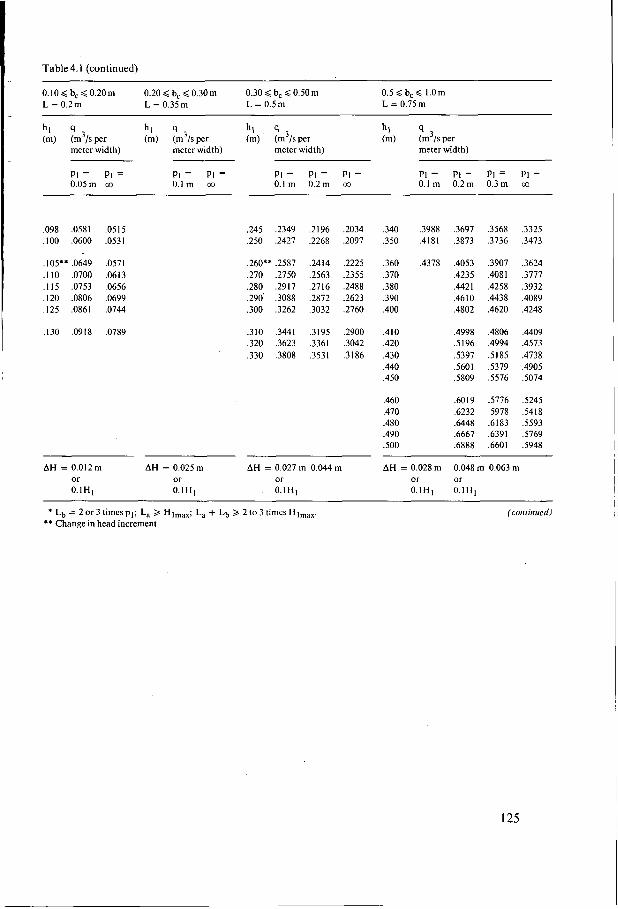
Table 4.1 (continued)
0 . 1 0 $ b C ~ 0 . 2 0 m 0.20$ bC40.30m 0 . 3 0 4 b C 4 0 . 5 0 m 0.5 4 b, 4 1.0m L = 0.2 m L = 0.5m L = 0.75 m L = 0.35 m
PI = PI = PI = PI = PI = PI = PI = PI = PI = PI = PI = 0.05m m 0.1 m m 0.1 m 0.2m m O.lm 0.2m 0.3m m
.O98 ,0581
.IO0 ,0600
.105** ,0649
.I10 ,0700
.I15 .O753 ,120 .O806 ,125 .O861
,130 ,0918
.o5 15
.O531
.O571
.O61 3 ,0656 ,0699 .O744
.O789
,245 .2349 ,250 .2427
.260** ,2587
.270 ,2750 ,280 ,2917 .290' ,3088 ,300 ,3262
.310 ,3441 ,320 ,3623 ,330 ,3808
.2 I96
.2268
.2414 ,2563 ,2716 ,2872 ,3032
,3195 .3361 .3531
,2034 ,2097
,2225 ,2355 .2488 .2623 .2760
.2900 ,3042 ,3186
AH = 0.01 2 m AH = 0.025m AH = 0.027 m 0.044 m or or or O.lHI O.IHI . 0.1H1
.340 .3988 .3697 ,3568 ,3325 ,350 .4181 ,3873 ,3736 ,3473
.360 ,4378 .4053 ,3907 ,3624
.370 .4235 ,4081 ,3777 ,380 ,4421 ,4258 ,3932 .390 ,4610 ,4438 ,4089 .400 ,4802 ,4620 .4248
,410 ,4998 .4806 ,4409 ,420 ,5196 ,4994 ,4573 ,430 ,5397 ,5185 ,4738 ,440 ,5601 S379 .4905 ,450 SS09 3 7 6 SO74
,460 .6019 ,5776 ,5245 .470 .6232 ,5978 ,5418 ,480 ,6448 .6183 ,5593 .490 .6667 ,6391 ,5769 SO0 .6888 ,6601 S948
AH = 0.028 m 0.048 m 0.063 m or or 0.1H1 0.1H1
* L~ = 2 or 3 times pI; La > Hlmax; La + Lb > 2 to 3 times Hlmax. ** Change in head increment
(continued)
125
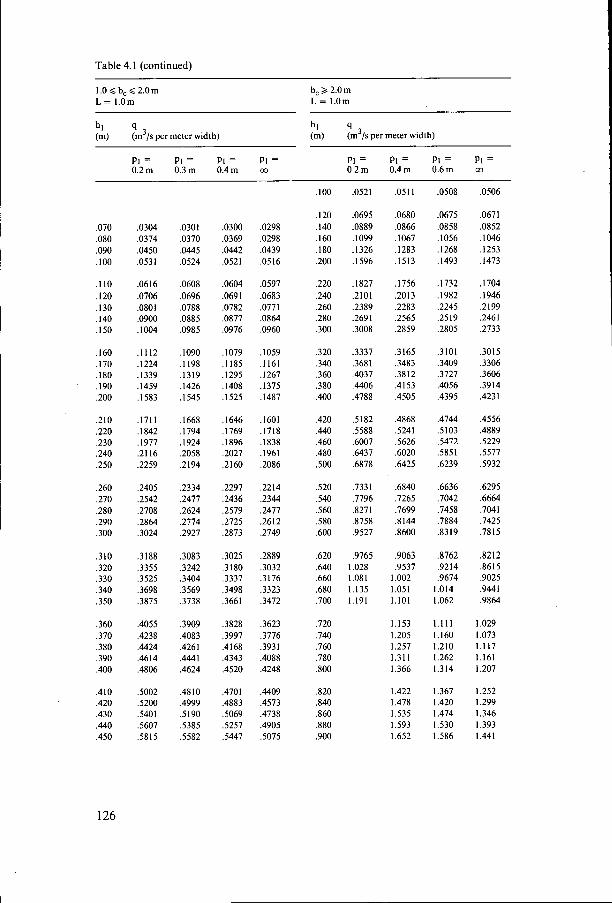
Table 4.1 (continued)
1.0 < b, < 2.0m L = I.Om
hl (m) q (m3/s per meter width) (m) (m3/s per meter width)
b, 3 2.0 m L = 1.0m
hl 4
PI = PI = PI = PI = PI = PI = PI = PI = 0.2m 0.3m 0.4m co 0.2m 0.4m 0.6m 00
.O70
.O80
.O90 ,100
.I10
.I20
. I30 ,140 . I50
.I60
.I70
.I80 . .I90
.200
.210 ,220 .230 ,240 ,250
.260
.270
.280
.290
.300
,310 .320 ,330 .340 ,350
,360 ,370 .380 .390 .400
,410 .420 .430 ,440 .450
,0304 ,0374 ,0450 ,0531
.O6 I 6
.O706 ,0801 .O900 .I004
,1112 .I224 . I339 ,1459 ,1583
,1711 .I842 ,1977 .2116 .2259
,2405 ,2542 ,2708 ,2864 ,3024
,3188 ,3355 ,3525 ,3698 ,3875
.4055 ,4238 ,4424 ,4614 ,4806
,5002 ,5200 ,5401 ,5607 ,5815
.O301
.O370
.O445 ,0524
,0608 ,0696 .O788 .O885 ,0985
.I090
. I 198 ,1319 ,1426 ,1545
,1668 ,1794 ,1924 ,2058 ,2194
,2334 ,2477 ,2624 ,2774 ,2927
,3083 .3242 ,3404 ,3569 ,3738
.3909 ,4083 ,4261 ,4441 ,4624
.48 I O ,4999 ,5190 S385 ,5582
,0300 ,0369 ,0442 ,0521
,0604 ,0691 .O782 .O877 .O976
.I079 , I 185 .I295 . I408 ,1525
. I646 ,1769 ,1896 ,2027 ,2160
.2291 ,2436 ,2579 ,2725 ,2873
,3025 ,3180 ,3337 ,3498 ,3661
,3828 ,3997 .4 168 ,4343 ,4520
,4701 ,4883 ,5069 S257 ,5447
.O298
.O298
.O439
.O516
.O597
.O683 ,0771 .O864 .O960
,1059 .I161 .I267 ,1375 ,1487
,1601 .I718 ,1838 .I961 ,2086
,2214 ,2344 ,2477 .26 I2 ,2749
,2889 ,3032 .3176 ,3323 ,3472
,3623 ,3776 .3931 ,4088 .4248
,4409 .4573 .4738 ,4905 ,5075
,100
. I20 ,140 .I60 ,180 .200
,220 .240 .260 .280 .300
.320
.340
.360 ,380 .400
.420 ,440 ,460 ,480 ,500
,520 ,540 ,560 ,580 ,600
,620 ,640 ,660 ,680 ,700
,720 ,740 ,760 ,780 ,800
3 2 0 ,840 ,860 380 ,900
.O521
.O695 ,0889 .I099 .I326 .I596
,1827 .2101 ,2389 .2691 .3008
,3337 .3681 .4037 ,4406 ,4788
,5182 ,5588 ,6007 ,6437 ,6878
,7331 ,7796 ,8271 ,8758 ,9527
,9765 1 .O28 1 .O8 I 1.135 1.191
.o51 I
,0680 .O866 ,1067 .I283 ,1513
,1756 ,2013 ,2283 .2565 ,2859
.3165 ,3483 .3812 ,4153 ,4505
,4868 ,5241 ,5626 ,6020 ,6425
.6840 ,7265 .7699 ,8144 ,8600
,9063 ,9537
1.002 1.051 1.101
1.153 1.205 1.257 1.311 1.366
1.422 1.478 1.535 1.593 1.652
,0508
,0675 ,0858 ,1056 . I268 ,1493
,1732 ,1982 ,2245 ,2519 ,2805
,3101 ,3409 ,3727 ,4056 ,4395
,4744 ,5103 ,5472 ,5851 ,6239
.6636 ,7042 ,7458 ,7884 ,8319
3762 .9214 .9674
1.014 I .O62
1.111 1.160 1.210 1.262 1.314
1.367 1.420 1.474 1.530 1.586
,0506
,0671 ,0852 . I046 .1253 ,1473
,1704 .1946 .2199 ,2461 .2733
,3015 ,3306 .3606 .3914 ,4231
.4556 ,4889 5229 ,5577 5932
.6295
.6664
.7041
.7425
.7815
,8212 ,8615 .9025 .9441 .9864
1 .O29 I .O73 1.117 1.161 1.207
1.252 I .299 1.346 1.393 1.441
126
i
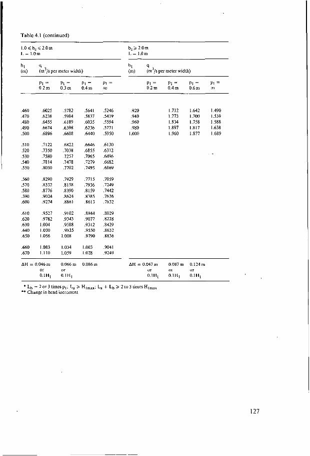
Table 4.1 (continued)
1.0 4 b, 4 2.0 m L = I.Om
b, 2 2.0 m L = 1.0m
hl q hl q (m) (m3/s per meter width) (m) (m3/s per meter width)
PI = PI = PI = PI = O.2m 0.4m 0.6m
p1 = PI = PI = PI = 0.2 m 0.3 m 0.4m
,460 ,470 ,480 ,490 so0
S I 0 .520 ,530 .540 .550
,560 ,570 ,580 ,590 ,600
,610 ,620 ,630 ,640 .650
,660 ,670
.6025 ,6238 ,6455 5674 ,6896
,7122 ,7350 .7580 .7814 3050
3290 .8532 ,8776 ,9024 .9274
,9527 .9782
1 .O04 1 .O30 1.056
1 .O83 1.110
,5782 ,5984 ,6189 ,6398 ,6608
.6822
.7038
.7257 ,7478 ,7702
,7929 ,8158 ,8390 ,8624 ,8861
,9102 ,9343 ,9588 .9835
1 .O08
I .O34 I .O59
,5641 ,5837 ,6035 .6236 .6440
.6646 ,6855 ,7065 ,7279 ,7495
,7715 ,7936 ,8159 ,8385 ,8613
.8844 ,9077 .9312 .9550 ,9790
I .O03 I .O28
,5246 ,920 1.712 S419 .940 1.773 3 9 4 .960 1.834 ,5771 .980 1.897 ,5950 I .o00 1.960
,6130 .63 I2 ,6496 ,6682 ,6869
.7059
.7249 ,7442 ,7636 ,7832
,8029 ,8228 ,8429 ,8632 ,8836
,9041 ,9249
,642 1.490 ,700 1.539 ,758 1.588 817 1.638 ,877 1.689
AH = 0.046 m 0.066 m 0.086 m AH = 0.047 m 0.087 m 0.124 m or or or or or 0 .1H1 O.IH1 0.1H1 0.1H1 O.IH1
* L~ = 2 or 3 times pI; La 2 HImax; La + Lb > 2 to 3 times Himax ** Change in head increment
127
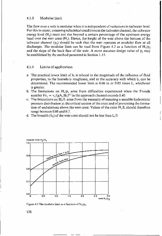
4.1.3 Modular limit
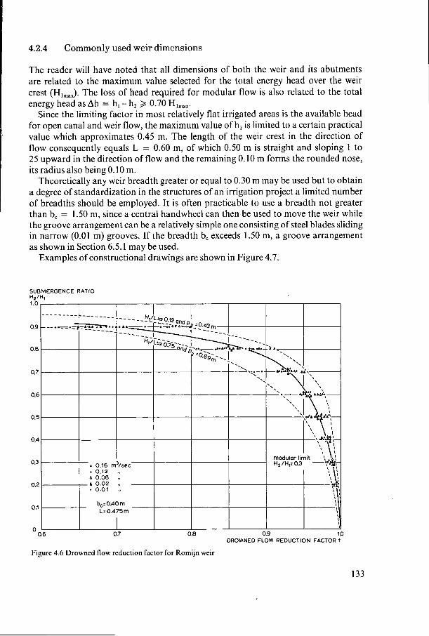
The flow over a weir is modular when it is independent of variations in tailwater level. For this to occur, assuming subcritical conditions in the tailwater channel, the tailwater energy level (H,) must not rise beyond a certain percentage of the upstream energy head over the weir crest (HI). Hence, the height of the weir above the bottom of the tailwater channel (p,) should be such that the weir operates at modular flow at all discharges. The modular limit can be read from Figure 4.2 as a function of H,/p, and the slope of the back face of the weir. A more accurate design value of p2 may be established by the method persented in Section I . 15.
4.1.4 Limits of application
a. The practical lower limit of h, is related to the magnitude of the influence of fluid properties, to the boundary roughness, and to the accuracy with which h, can be determined. The recommended lower limit is 0.06 m or 0.05 times L, whichever is greater.
b. The limitations on HJp, arise from difficulties experienced when the Froude number Fr, = V , / ( ~ A , / B , ) ~ . ~ in the approach channel exceeds 0.45.
c. The limitations on H,/L arise from the necessity of ensuring a sensible hydrostatic pressure distribution at the critical section of the crest and of preventing the forma- tion of undulations above the weir crest. Values of the ratio H,/L should therefore range between 0.08 and 0.7.
d. The breadth (b,) of the weir crest should not be less than L/5.
modular limit H2/H,
ratio H1/p2
Figure 4.2 The modular limit as a function of H,/pz
128
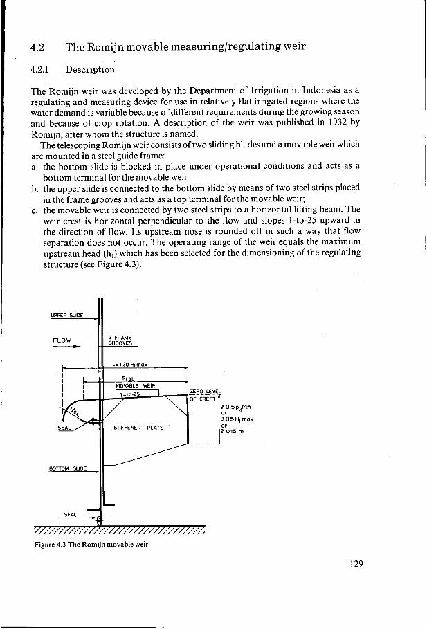
4.2 The Romijn movable measuring/regulating weir
4.2.1 Description
The Romijn weir was developed by the Department of Irrigation in Indonesia as a regulating and measuring device for use in relatively flat irrigated regions where the water demand is variable because of different requirements during the growing season and because of crop rotation. A description of the weir was published in 1932 by Romijn, after whom the structure is named.
The telescoping Romijn weir consists of two sliding blades and a movable weir which are mounted in a steel guide frame: a. the bottom slide is blocked in place under operational conditions and acts as a
bottom terminal for the movable weir b. the upper slide is connected to the bottom slide by means of two steel strips placed
in the frame grooves and acts as a top terminal for the movable weir; c. the movable weir is connected by two steel strips to a horizontal lifting beam. The
weir crest is horizontal perpendicular to the flow and slopes 1-to-25 upward in the direction of flow. Its upstream nose is rounded off in such a way that flow separation does not occur. The operating range of the weir equals the maximum upstream head (h,) which has been selected for the dimensioning of the regulating structure (see Figure 4.3).
5 0.5 p2min or 3 0.5 H, max or 50.15 m
STIFFENER PLATE '
BOTTOM SIDE
Figure 4.3 The Romijn movable weir
iR 2 PLATE p5m
129
Although the Romijn weir has been included in this chapter on broad-crested weirs, from a purely hydraulic point of view this is not quite correct. Above the I-to-25 sloping weir crest the streamlines are straight but converging so that the equipotential lines are curved. At the same time, the control section is situated more towards the end of the crest than if the crest were truly horizontal. Therefore, the degree of down- ward curvature of the overflowing nappe has a significant influence on the C,-value.
To prevent the formation of a relatively strong eddy beneath the weir crest and the overflowing nappe, the weir should have a vertical downstream face. The reason for this is that especially under submerged flow conditions the nappe will deflect up- wards due to the horizontal thrust of the eddy, resulting in up to 7% lower weir flows. The downstream weir face, which breaks the force of the eddy should have a minimum height of 0.5 pzmln or 0.5 Hlma, or O. 15 m, whichever is greater.
'As mentioned, the bottom slide, and thus the upper slide, is blocked in place during normal flow conditions. However, to flush sediments that have collected upstream of the weir, both slides can be unlocked and raised by moving the weir crest upward. After flushing operations the slides are pushed in place again by lowering the weir crest. To discourage misuse of the weir, the maximum flow capacity beneath the lifted bottom gate must be less than the flow over the weir in its lowest position. For this to occur, the travel of the upper gate is restricted so that the bottom gate cannot be lifted higher than 0.5 Hlma, above the approach channel bottom.
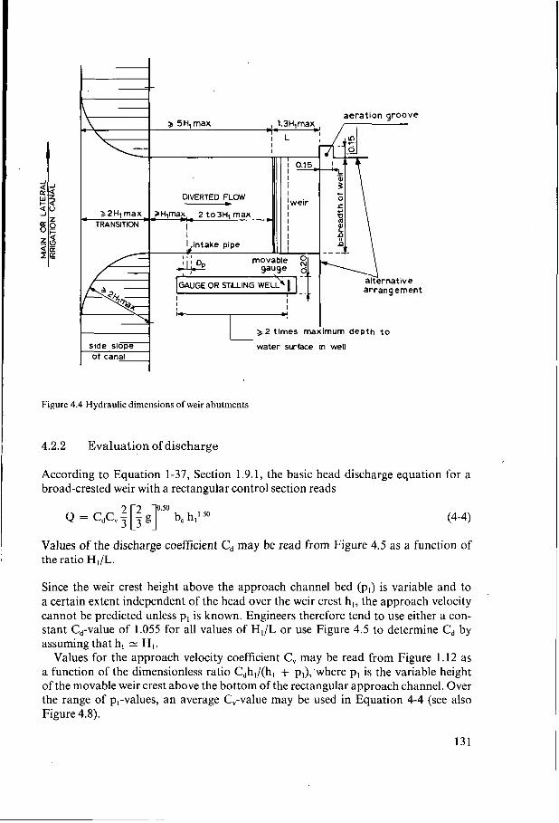
The weir abutments are vertical and are rounded in such a way that flow separation does not occur. A rectangular approach channel is formed to assure an even flow distribution. The upstream head over the weir, h,, is measured in this approach channel at a distance of between two and three times Hlmax upstream of the weir face. The dimensions of the abutment should comply with the requirements indicated in Figure 4.4. The radius of the upstream rounding-off of the abutments may be reduced to r k Hlma, if the centre line of the weir structure is parallel to or coincides with the centre line of the undivided supply canal (in-line structure) or if the water is drawn direct from a (storage) basin.
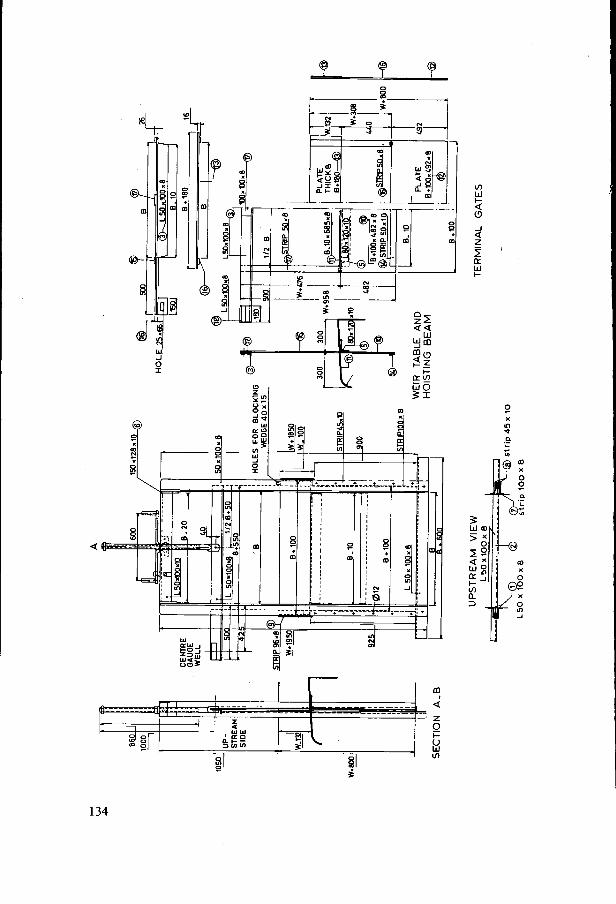
If several movable weirs are combined in a single structure, intermediate piers should be provided so that two-dimensional flow is preserved over each weir unit, allowing the upstream head over the weir to be measured independently per unit. The parallel section of the pier should therefore commence at a point located at a distance of H,,,, upstream of the head measurement station and extend to the downstream edge of the weir crest. Piers should have streamlined noses, i.e. of semi-circular or tapered semi-elliptical profile (i-to-3 axis). To avoid extreme velocity differences over short distances, the thickness of the intermediate piers should be equal to or more than 0.65 Hlma,, with a minimum of 0.30 m.
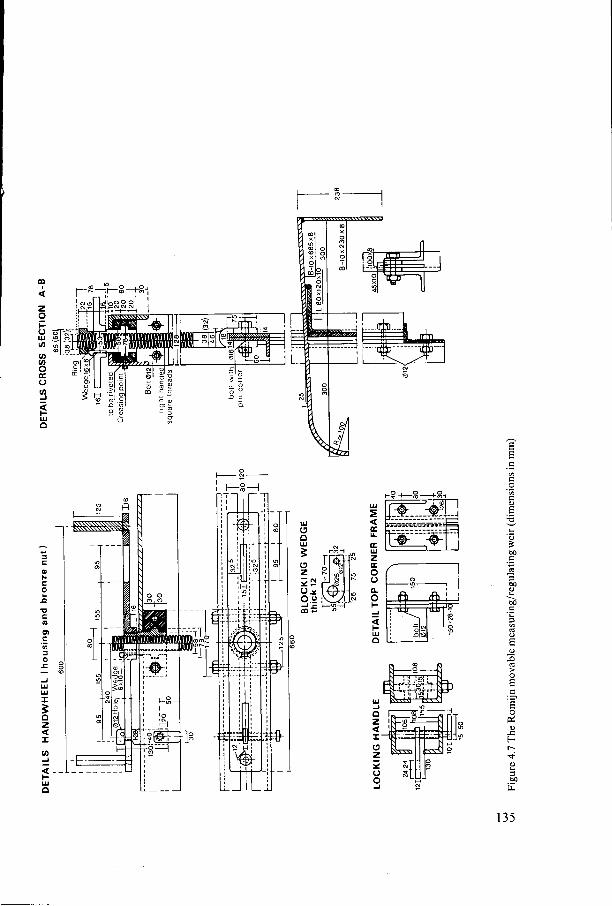
Since the weir crest moves up and down, a fixed staff gauge at the head measurement station does not provide a value for the upstream head over the crest unless the weir crest elevation is registered separately in terms of gauged head. To avoid this proce- dure, the weir is equipped with a gauge that moves up and down with the weir crest (see Fig. 4.4). Zero level of this gauge coincides with the downstream edge of the weir crest, so that the upstream head over the crest equals the immersed depth of the gauge and can be read without time lag. The movable gauge is attached to the extended lifting beam as shown in Figure 4.7.
130
_ _
aeration groove 3 5H,max
DIVERTED FLOW - 22H1max- - - 2 H p u ~ - - .- 2 t03H1max
TRANSITION
arrangement
3 2 times maximum depth to I
water surface in well
Figure 4.4 Hydraulic dimensions of weir abutments
4.2.2 Evaluation of discharge
According to Equation 1-37, Section 1.9.1, the basic head discharge equation for a broad-crested weir with a rectangular control section reads
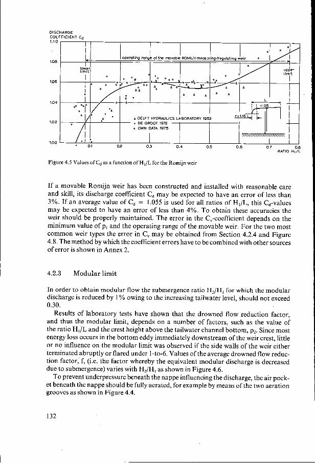
Values of the discharge coefficient Cd may be read from Figure 4.5 as a function of the ratio HJL.
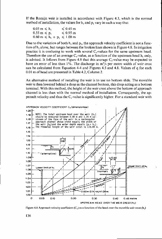
Since the weir crest height above the approach channel bed (p,) is variable and to a certain extent independent of the head over the weir crest h,, the approach velocity cannot be predicted unless p, is known. Engineers therefore tend to use either a con- stant C,-value of 1.055 for all values of H,/L or use Figure 4.5 to determine Cd by assuming that h, N HI.
Values for the approach velocity coefficient C, may be read from Figure 1.12 as a function of the dimensionless ratio Cdhl/(hl + p,);where p, is the variable height of the movable weir crest above the bottom of the rectangular approach channel. Over the range of p,-values, an average C,-value may be used in Equation 4-4 (see also Figure 4.8).
131