3d display systems - wikileaks 3d display... · 3d display systems dr nick holliman, department of...
TRANSCRIPT

3D Display Systems
Dr Nick Holliman,Department of Computer Science, University of Durham,Science Laboratories, South Road, Durham, DH1 3LE.
February 2, 2005
Contents
1 Introduction 3
2 Human Depth Perception 42.1 Monocular and oculomotor depth cues . . . . . . . . . . . . . . . 42.2 Binocular depth perception in the natural world . . . . . . . . . . 62.3 Depth perception in electronic stereoscopic images. . . . . . . . . 92.4 Benefits of binocular vision . . . . . . . . . . . . . . . . . . . . . . 12
3 3D Display Designs using Micro-optics 143.1 Stereoscopic Systems . . . . . . . . . . . . . . . . . . . . . . . . . 153.2 Autostereoscopic Systems . . . . . . . . . . . . . . . . . . . . . . 163.3 Two view twin-LCD systems. . . . . . . . . . . . . . . . . . . . . 173.4 A Note on Viewing Windows . . . . . . . . . . . . . . . . . . . . . 203.5 Two-view single LCD systems . . . . . . . . . . . . . . . . . . . . 22
3.5.1 Parallax barrier designs . . . . . . . . . . . . . . . . . . . 223.5.2 Lenticular element designs . . . . . . . . . . . . . . . . . . 273.5.3 Micro-polariser designs . . . . . . . . . . . . . . . . . . . . 313.5.4 Holographic elements . . . . . . . . . . . . . . . . . . . . . 32
3.6 Multi-view systems . . . . . . . . . . . . . . . . . . . . . . . . . . 32
4 3D Display Performance and Use 374.1 Comparing perceived depth reproduction . . . . . . . . . . . . . . 374.2 Perceived depth control and image generation . . . . . . . . . . . 41
5 Summary 42
1
3D Display Systems 2
List of Figures
1 Picture illustrating the depth cues available in a 2D image, (pho-tographer David Burder). . . . . . . . . . . . . . . . . . . . . . . 5
2 The geometry of the binocular vision when viewing the naturalworld. . . . . . . . . . . . . . . . . . . . . . . . . . . . . . . . . . 6
3 Angular disparity is defined relative to the current fixation point. 74 Stereo acuity defines smallest depth difference an observer can per-
ceive. . . . . . . . . . . . . . . . . . . . . . . . . . . . . . . . . . 85 Perceived depth behind (1) and in front (2) of the display plane. . 116 The VREX micro-polariser stereoscopic display principle. . . . . . 167 Two-view displays create two viewing windows. . . . . . . . . . . 188 The Sharp twin-LCD display, [12]. . . . . . . . . . . . . . . . . . . 189 The Sharp micro-optic twin-LCD display, [63]. . . . . . . . . . . . 1910 Viewing freedom in an autostereoscopic display, [63]. . . . . . . . 2111 The characteristics of a viewing window, [63]. . . . . . . . . . . . 2112 The principle of the front parallax barrier. . . . . . . . . . . . . . 2213 Detail of a single LCD front parallax barrier design, [64]. . . . . . 2414 The VPI display operation (a) in image region and (b) in indicator
region, [64]. . . . . . . . . . . . . . . . . . . . . . . . . . . . . . . 2615 Front lenticular autostereoscopic display principle, [52]. . . . . . . 2816 The geometry of rear parallax illumination by light lines. . . . . . 2917 The DTI compact backlight allowing 2D/3D illumination. . . . . 3018 The Sharp micro-polariser display with 2D/3D switching capabil-
ity, [20]. . . . . . . . . . . . . . . . . . . . . . . . . . . . . . . . . 3119 Multi-view displays create multiple viewing windows. . . . . . . . 3320 The principle of a multi-view front lenticular autostereoscopic dis-
play. . . . . . . . . . . . . . . . . . . . . . . . . . . . . . . . . . . 3421 The slanted arrangement of the lenticular lens and pixels in the
Philips multi-view display, [57]. . . . . . . . . . . . . . . . . . . . 3522 The perceived depth represented by corresponding pixels of 0 and
2 pixels screen disparity. . . . . . . . . . . . . . . . . . . . . . . . 3823 Stereoscopic resolution is defined by planes of stereoscopic voxels. 4024 Table comparing characteristics of the generic displays and the eye. 40

3D Display Systems 3
1 Introduction
Today’s 3D display systems provide new advantages to end-users; they are ableto support an auto-stereoscopic, no-glasses, 3D experience with significantly en-hanced image quality over previous generation technology. There have been par-ticularly rapid advances in personal auto-stereoscopic 3D display for desktop usersbrought about because of the opportunity to combine micro-optics and LCD dis-plays coinciding with the availability of low cost desktop image processing and3D computer graphics systems.
In this chapter we concentrate our detailed technical discussion on personal 3Ddisplays designed for desktop use as these are particularly benefiting from newmicro-optic elements. We emphasize the systems aspect of 3D display designbelieving it is important to combine good optical design and engineering withthe correct digital imaging technologies to obtain a high quality 3D effect forend users. The general principles discussed will be applicable to the design of alltypes of stereoscopic 3D display.

3D Display Systems 4
2 Human Depth Perception
Defining the requirements for 3D display hardware and the images shown on themis an important first step towards building a high quality 3D display system. Weneed a clear understanding of how a digital stereoscopic image is perceived by anend user in order to undertake valid optimisation during the design process.
Binocular vision provides humans with the advantage of depth perceptionderived from the small differences in the location of homologous, or corresponding,points in the two images incident on the retina of the eyes. This is known asstereopsis (literally solid seeing) and can provide precise information on the depthrelationships of objects in a scene.
The human visual system also makes use of other depth cues to help interpretthe two images incident on the retina and from these build a mental model ofthe 3D world. These include monocular depth cues (also known as pictorial [18]or empirical [40] cues), whose significance is learnt over time, oculomotor cues inaddition to the stereoscopic cue [40]. We consider these in turn and introduce indetail binocular vision both in the natural world and when looking at an electronic3D display.
2.1 Monocular and oculomotor depth cues
Redundancy is built into the visual system and even people with monocular visionare able to perform well when judging depth in the real world. Therefore in thedesign of 3D displays it is important to be aware of the major contribution ofmonocular 2D depth cues in depth perception and aim to provide displays withat least as good basic imaging performance as 2D displays. Ezra [12] suggests thisshould include levels of brightness, contrast, resolution and viewing range thatmatch a standard 2D display with the addition of the stereoscopic cue providedby generating a separate image for each eye.
The monocular depth cues are experiential and over time observers learn thephysical significance of different retinal images and their relation to objects inthe real world. These include:
• Interposition: objects occluding each other suggest their depth ordering.
• Linear perspective: the same size object at different distances projects adifferent size image onto the retina.
• Light and Shade: the way light reflects from objects provides cues to theirdepth relationships, shadows are particularly important in this respect.
• Relative Size, an object with smaller retinal image is judged further awaythan the same object with a larger retinal image.

3D Display Systems 5
• Texture Gradient: a texture of constant size objects, such as pebbles orgrass, will vary in size on the retina with distance.
• Aerial Perspective: the atmosphere affects light travelling through it, forexample due to fog, dust or rain. As light travels long distances it is scat-tered, colours loose saturation, sharp edges are diffused and colour hue isshifted towards blue.
Texture Gradient
Perspective
Aerial distortion
Known
objects
Shading
Occlusion
Figure 1: Picture illustrating the depth cues available in a 2D image, (photogra-pher David Burder).
Many of these cues are illustrated in figure 1 and can be considered to be 2Ddepth cues since they are found in purely monoscopic images.
Two other non-binocular depth cues are available: motion parallax and ocu-lomotor cues.
Motion parallax provides the brain with a powerful cue to 3D spatial rela-tionships without the use of stereopsis [40, 18] and this is the case when eitheran object in the scene or the observer’s head moves. Motion parallax does not,however, make stereopsis redundant, as comprehending images of complex scenescan be difficult without binocular vision. Yeh [68] and others have shown thatboth stereopsis and motion parallax combined result in better depth perceptionthan either cue alone.
Oculomotor depth cues are due to feedback from the muscles used to controlthe vergence and accommodation of the eye. They are generally regarded as

3D Display Systems 6
having limited potential to help depth judgement [40, 42, 16] and we will moveon to consider how human binocular vision works when used to view the naturalworld.
2.2 Binocular depth perception in the natural world
Extracting three-dimensional information about the world from the images re-ceived by the two eyes is a fundamental problem for the visual system. In manyanimals perhaps the best way of doing this comes from the binocular disparitythat results from two forward facing eyes having a slightly different viewpointof the world [5]. The binocular disparity is processed by the brain giving thesensation of depth known as stereopsis.
L
R
Horopter
Panum’s Fusion
The horopter is all
points perceived at the
same depth as the point
of fixation, F.
F
All objects within Panum’s
fusion are seen as single
fused images
Figure 2: The geometry of the binocular vision when viewing the natural world.
Stereo depth perception in the natural world is illustrated in figure 2. Thetwo eyes verge the visual axes so as to fixate the point F and adjust their accom-modation state so that points in space at and around F come into focus.
The vergence point, F , projects to the same position on each retina and there-fore has zero retinal disparity, i.e. there is no difference between its location inthe left and right retinal images. Points in front or behind the fixation pointproject to different positions on the left and right retina and the resulting binoc-ular disparity between the point in the left and right retinal images provides the

3D Display Systems 7
observer’s brain with the stereoscopic depth cue. Depth judgement is thereforerelative to the current vergence point, F , and is most useful to make judgementson the relative rather than absolute depth of objects in a scene.
Points in space, other than F , which project zero retinal disparity are per-ceived to lie at the same depth as the vergence point, all points that projectzero retinal disparity are described as being on a surface in space known as thehoropter. The shape of the horopter shown in figure 2 is illustrative only it isknown in practice to be a complex shape and to have non-linear characteristics[3, 18].
L
R
Horopter
F ABb f a
Figure 3: Angular disparity is defined relative to the current fixation point.
Geometrically we can define angular disparity, α, as the difference between thevergence angle at the point of fixation, F and the point of interest. Consideringfigure 3:
Points behind the fixation point, such as A, have positive disparity.
αa = f − a (1)
Points in front of the fixation point, such as B, have negative disparity.
αb = f − b (2)
The smallest perceptible change in angular disparity between two small ob-jects is referred to as stereo acuity, δ, [67]. The advantage of defining stereo

3D Display Systems 8
acuity as an angle is that it can be assumed to be constant regardless of theactual distance to and between the points A and B. However, it is also helpfulto know how this translates in terms of the smallest perceived distance betweenobjects at the typical viewing range of a desktop 3D display. This will allow usto compare the ability of the eye to perceive depth with the ability of differentdisplays designs to reproduce it.
L
R
A
a
C
ce
m n
Figure 4: Stereo acuity defines smallest depth difference an observer can perceive.
Considering figure 4 when points A and C can just be perceived to be at adifferent depth then stereo acuity will be:
δ = a− c (3)
Various studies [67, 28, 31] show the eye is able to distinguish very small valuesof δ, as little as 1.8” (seconds of arc). As the exact limits vary between peopleDiner and Fender [8] suggest that a practical working limit is to use a value ofstereo acuity δ = 20”. Using this value we can calculate the size of the smallestdistinguishable depth difference at a given distance from the observer. We choosem = 750mm as the distance from the observer as a common viewing distance fordesktop stereoscopic displays and use an average eye separation, e = 65mm.
Calculating along the centre line between the visual axes we can find theminimum distinguishable depth, n, at distance m by considering points A andC. The angle a can be calculated as:
a = 2 ∗ arctan
((e/2)
m
)= 2 ∗ arctan
(32.5
750
)(4)

3D Display Systems 9
by the definition of stereo acuity we know that:
tan(c/2) = tan
(a− δ
2
)= tan
(a− 20”
2
)(5)
and if n is the distance between A and C we also know that:
tan(c/2) =(e/2)
m + n(6)
rearranging (6) we have:
n =
((e/2)
tan(c/2)
)−m (7)
Substituting (4) in (5) and using the result to solve (7) gives n = 0.84mm.We can conclude that a person with a stereo acuity of 20” and an eye sepa-
ration of 65mm will be able to perceive depth differences between small objectsof just 0.84mm at a distance of 750mm from the eyes.
It is also possible to calculate a geometric value for the furthest possible rangeof stereo vision which occurs when the vergence angle between the two visual axesis equal to or less than the stereo acuity.
The distance m from the observer to the point A when the angle a = δ isgiven by
m =(e/2)
tan(a/2)(8)
Again taking δ = 20” and e = 65mm we get m = 670m.This means that points such as C at a distance of 670m or more from the
observer will not be able to be distinguished in distance from A using binocularvision alone. Just before this limit is reached the smallest distinguishable depthdifference between points will have increased to over 300m and it is clear onlygross differences in depth will be perceived at the furthest limits of stereoscopicperception.
To summarise the above, binocular vision uses the stereoscopic depth cueof retinal disparity to perceive an object’s depth relative to the fixation pointof the two eyes. At close and near range this provides a high degree of depthdiscrimination and even at tens of metres from the observer enables relative depthperception for larger objects.
2.3 Depth perception in electronic stereoscopic images.
Wheatstone [62] demonstrated that the stereoscopic depth sensation could berecreated by showing each eye a separate 2D image. The left and right eye viewsshould be 2D planar images of the same scene from slightly different viewpoints;the difference in the viewpoints generates disparity in the images. When theimages are subsequently viewed the observer perceives depth in the scene because

3D Display Systems 10
the image disparity creates a retinal disparity similar, but not identical, to thatseen when looking directly at a natural scene.
Wheatstone was able to demonstrate this effect by building the first stereo-scope and many devices have since been invented for stereoscopic image presenta-tion each with their own optical configurations. Reviews of these devices and thehistory of stereoscopic imaging are available in several sources [23, 55, 41, 33, 30].
To help characterise and compare the performance of different electronic 3Ddisplay designs we will consider the perception of depth in planar stereo imagepairs and how this differs from the stereoscopic perception of depth in the naturalworld.
A key physiological difference is that although the eyes need to verge off thestereoscopic image plane to fixate points in depth their accommodation statemust always keep the image plane itself in focus. This requires the observer tobe able to alter the normal link between vergence and accommodation and is onereason why images with large perceived depth are hard to view. This suggeststhat the perceived depth range in stereoscopic image pairs needs to be limited toensure the observer will find a stereo image pair comfortable to view.
While there are several studies of the comfortable perceived depth range onelectronic 3D displays [67, 17, 66] it can be difficult to factor out variables relatingto display performance from the results. Display variables include absolute values,and inter-channel variations, of brightness and contrast in addition to stereoscopicimage alignment and crosstalk. All of these can affect the comfortable range ofperceived depth on a particular display. For example high crosstalk displaysgenerally do not support deep images as the ghosting effect becomes more andmore intrusive to the observer as screen disparity is increased.
An analysis of the geometry of perceived depth assuming a display with idealproperties helps identify the geometric variables affecting perceived depth inde-pendently of the display used. Geometric models of perceived depth have beenstudied by Helmholtz [23] and Valyus [55] and more recently in [24, 66, 8, 27]We present a simplified model in figure 5 for discussion purposes which helpsemphasise the key geometric variables affecting the perception of stereoscopicimages.
Figure 5 shows the geometry of perceived depth for a planar stereoscopicdisplay, for simplicity we consider the geometry along the centre line of the displayonly, more general expressions are available [23, 66]. The viewers eyes, L and R,are separated by the interoccular distance, e, and are at a viewing distance, z,from the display plane. The screen disparity between corresponding points in theleft and right images, d, is a physical distance resulting from the image disparitywhich is a logical value measured in pixels. Image disparity is constant for a givenstereo pair, however screen disparity will vary depending on the characteristics ofthe physical display. Screen disparity in a pair of aligned stereo images is simplythe difference of the physical x coordinates of corresponding points in the right

3D Display Systems 11
L
R
L
R
d
d
p
p
z
z
e
e
p, perceived depth
z, viewing distance
e, eye separation
d, screen disparity
Figure 5: Perceived depth behind (1) and in front (2) of the display plane.
xr and left xl images:d = xr − xl (9)
Two key expression relating screen disparity to perceived depth can be derivedfrom the similar triangles in figure 5. Perceived depth behind the screen plane,i.e. positive values of d, is given by:
p =z(
e|d|
)− 1
(10)
Perceived depth in front of the screen plane, i.e. negative values of d, is given by:
p =z(
e|d|
)+ 1
(11)
Equations (10) and (11) provide several insights into the geometric factorsaffecting perceived depth:
• z, the viewing distance to the display. Perceived depth is directly propor-tional to the viewing distance, z. Therefore a viewer looking at the samestereoscopic image from different distances perceives different depth. Howimportant this is, is application dependent, but applications such as CAD,medical imaging and scientific imaging may critically depend on accurateand consistent depth judgements.

3D Display Systems 12
• d, the screen disparity. Perceived depth is also directly proportional toscreen disparity, d. The screen disparity for any given stereoscopic imagevaries if the image is displayed at different sizes, either in different size win-dows on the same screen or on different size screens. Again this is importantto note in applications where depth judgement is a critical factor. It meansstereoscopic images are display dependent and an image displayed on alarger display than originally intended could exceed comfortable perceiveddepth limits or give a false impression of depth.
• e, individual eye separation. Perceived depth is inversely proportional toindividual eye separation which varies over a range of approximately 55mmto 75mm with an average value often taken as 65mm. Children can havesmaller values of eye separation and therefore see significantly more per-ceived depth in a stereoscopic image than the average adult. It may be par-ticularly important to control perceived depth in systems intended for useby children, as they will reach the limits of their vergence/accommodationcapabilities sooner than most adults.
For display design controlling these variables so that the viewer sees a consis-tent representation of depth ideally requires tracking head position, identifyingeye separation and controlling screen disparity. These are challenging goals inaddition to designing a display with as good imaging performance as a 2D dis-play.
2.4 Benefits of binocular vision
An important question is what advantages does binocular vision provide in thereal world? As a visual effect it clearly fascinates the majority of people whenthey see a 3D picture. Beyond the attractive nature of stereoscopic 3D imagesthey provide the following benefits over monocular vision:
• Relative depth judgement. The spatial relationship of objects in depth fromthe viewer can be judged directly using binocular vision.
• Spatial localisation. The brain is able to concentrate on objects placed ata certain depth and ignore those at other depths using binocular vision.
• Breaking camouflage. The ability to pick out camouflaged objects in a sceneis probably one of the key evolutionary reasons for having binocular vision[49].
• Surface material perception. For example, lustre [23], sparkling gems andglittering metals are in part seen as such because of the different specularreflections detected by the left and right eyes.

3D Display Systems 13
• Judgement of surface curvature. Evidence suggests that curved surfacescan be interpreted more effectively with binocular vision.
These benefits make stereo image display of considerable benefit in certain pro-fessional applications where depth judgement is important to achieving successfulresults. In addition the effect of stereopsis is compelling enough that stereoscopicimages have formed the basis of many entertainment systems.

3D Display Systems 14
3 3D Display Designs using Micro-optics
The possible combinations of LCD and micro-optics provide many degrees offreedom for display design; the ideal 3D display design will depend on specificapplication requirements. However, there are characteristics that all display de-signs should give consideration to and we briefly review these here.
There is a need to compare the basic image quality of a 3D design to thatachieved by current 2D displays i.e. the 2D characteristics of a 3D display shouldmatch the performance of 2D displays as closely as possible. Key characteristicsare:
• Brightness, typical of a current LCD display is 150Cd/m2
• Contrast, typical of a current LCD display is 300 : 1
• Colour reproduction, measured white points and measured CIE coordinatesof primaries.
These values are typical of current 2D displays but are clearly be a moving targetas 2D displays improve.
In addition there are a number of important characteristics unique to 3Ddisplays. The first is the 2D characteristics need to be matched between all theviewing windows of the 3D display. Each viewing window should also be matchedspatially and temporally so that there is no noticeable position or time differencesbetween corresponding images.
Inter-channel crosstalk appears to an observer as a ghost image, which will beparticularly visible at high contrast edges in images. It is an unwanted featurein most display designs because high values of crosstalk are known to be detri-mental to 3D effect, particularly on high contrast displays showing large valuesof perceived depth [43]. Ideally crosstalk measurements need to be no more than0.3 percent if the ghosting effect is to be imperceptible to an observer. Crosstalk,although often due to optical effects in the display, can also result from poorseparation of the two image channels in the display driving electronics, imagecompression formats or the camera system generating the images.
An observer of a 2D display will usually expect to be able to see a goodquality image at a wide range of positions in front of the display. Because ofthe need to direct images separately to the two eyes many 3D displays have amore limited viewing freedom. Consideration needs to be given to the targetsfor lateral, vertical and perpendicular freedom in a display design. 3D displaysystems capable of supporting multiple observers will often do so at the expenseof viewing freedom. Improved viewing freedom can be found in designs withmultiple viewing windows or using head tracking to steer viewing windows tofollow the observers head movements. When head tracking is used a designneeds to consider targets for the maximum supported head speed as this directlydetermines key tolerances.

3D Display Systems 15
Some displays have the capability to operate in either 3D or 2D modes switch-ing electronically or mechanically between the two. In this case the image qualityin each mode needs to be considered against the performance of a standard 2Ddisplay, as a display in 3D mode will often have different optical performance tothe same display in 2D mode.
The capability of a 3D display to represent perceived depth is probably thesingle most important design target however we will return to how to quantifyand compare this between displays after presenting details of representative 3Ddisplay designs.
We would like 3D displays to provide the ability for the observer to accom-modate naturally at the fixation point. However, this is not a feature supportedin stereoscopic images and has been attempted in very few display designs.
3.1 Stereoscopic Systems
Stereoscopic displays require users to wear a device, such as analysing glasses,that ensures left and right views are seen by the correct eye. Many stereoscopicdisplay designs have been proposed and there are reviews of these in severalsources [55, 41, 33, 30, 35]. Most of these are mature systems and have becomeestablished in several professional markets but suffer from the drawback thatthe viewer has to wear, or be very close to, some device to separate the leftand right eye views. This has limited the widespread appeal of stereoscopicsystems as personal displays for home and office use even when the 3D effectis appealing. However, stereoscopic displays are particularly suited to multipleobserver applications such as cinema and group presentation where directingindividual images to each observer becomes difficult compared to providing eachobserver with a pair of analysing glasses.
As stereoscopic display systems are well described elsewhere we limit ourselveshere to a summary of the major types using electronic displays:
• Wheatstone mirror stereoscopes using CRT displays or LCD displays.
• Polarised glasses in combination with a method of polarising the two views.
• Shutter glasses working in synchronisation with a view switching display.
• Analglyph glasses analysing different colour channels to obtain the images.
• Brewster stereoscopes, of which head mounted displays are up to date ex-amples.
A series of stereoscopic display designs that use polarising micro-optics havebeen produced by the VREX company [14], as shown in figure 6. The micro-optics split a single display into two differently polarised views, which are viewedcorrectly by left and right eyes when the observer wears a pair of analysing

3D Display Systems 16
When viewed with polarised glasses the P1 polarised pixels
are seen only in the left eye and P2 polarised in the right.
A spatially multiplexed image (SMI) with left (L) and right (R) image pixels is
placed behind a patterned micro-polariser (uPol) element.
RL
LR
RL
LR
RL
LR
RL
LR
P2P1
P1P2
P2P1
P1P2
P2P1
P1P2
P2P1
P1P2
SMI uPol
P1
P2
Left (L) pixels
Right (R) pixels
Viewing glasses
Polarised
pixelsMultiplexed
pixels
g
Figure 6: The VREX micro-polariser stereoscopic display principle.
polarised glasses. This requires two half resolution views and may be achievedusing a checkerboard pattern of image multiplexing and polarisation as shown infigure 6 as the spatially multiplexed image (SMI) and patterned micro-polariser(uPol).
A drawback of the design, particularly for direct view LCD based displays, isthe parallax between the display pixels and the micro-polariser when the micro-polariser is mounted over the LCD due to the layer of substrate between thetwo elements forming the gap g in figure 6. If the head moves from the nominalviewing position part of the adjacent view’s pixel becomes visible resulting incrosstalk. One way to reduce this is to use interlace the images in alternate rowsso at least lateral head movement is not affected by parallax. As noted by Harrold[20] this problem can only be fully solved in the long term by manufacturing themicro-polariser element within the LCD pixel cells reducing the parallax betweenpolariser and pixel.
3.2 Autostereoscopic Systems
Autostereoscopic displays are those that do no require the observer to wear anydevice to separate the left and right views and instead send them directly tothe correct eye. This removes a key barrier to acceptance of 3D displays foreveryday use but requires a significant change in approach to 3D display design.Autostereoscopic displays using micro-optics in combination with an LCD ele-

3D Display Systems 17
ment have become attractive to display designers and several new 3D displaytypes are now available commercially. The key optical reasons [64] for combiningmicro-optics with LCD elements are:
• LCD offers pixel position tolerances better than 0.1um
• LCD pixels, unlike CRT pixels, have high positional stability.
• LCD elements have carefully controlled glass thickness.
Autostereoscopic displays have been demonstrated using a range of opticalelements in combination with an LCD including:
• Parallax barriers, optical apertures aligned with columns of LCD pixels.
• Lenticular optics, cylindrical lenses aligned with columns of LCD pixels.
• Micropolarisers are found in several autostereoscopic 3D display designs.
• Holographic elements have been used to create real images of a diffuse lightsource.
In the following we introduce how these elements are used in autostereoscopic3D display designs including two-view and multi-view designs. We begin bylooking at autostereoscopic two-view designs using twin-LCD elements.
3.3 Two view twin-LCD systems.
A successful approach to building high quality auto-stereoscopic displays has beento use two LCD elements and direct the image from one to the left eye and fromthe other to the right eye, the principle is illustrated in figure 7. Several designsadopted this approach including [12, 13, 22].
Ezra [12, 13] describes one of the Sharp designs which, produces bright, highquality, full colour moving 3D images over a wide horizontal viewing range. Asshown in figure 8 the display produces two viewing windows using a single illumi-nator. The arrangement of optical elements generates horizontally offset imagesof the illuminator at a nominal viewing distance to form the viewing windows.An observer’s eye placed in one of the viewing windows will see an image fromjust one of the LCD elements.
If a stereo pair of images is placed on the left and right LCD elements re-spectively then an observer will see a stereoscopic 3D image. The image appearsin the plane of the left LCD as the observer looks at the display and depth isperceived in front and behind this plane. As the two LCD’s are seen separatelyeach eye has a full resolution image and the interface is simply two synchronisedchannels of digital or analogue video which can be generated at low cost on adesktop PC system.

3D Display Systems 18
Each eye is able to see
the appropriate image on
the display through a
viewing “window”.
Left and right images are
displayed in different sets
of pixels on the display.
Display plane.
Figure 7: Two-view displays create two viewing windows.
Light
Source
Beam-splitter
Beam-combiner
Lens
Mirror
Lens LCD (Left)
LCD (Right)
Figure 8: The Sharp twin-LCD display, [12].

3D Display Systems 19
This basic configuration can be enhanced in several ways, if the light sourceis moved then the viewing windows can be steered to follow the observer’s headposition. In order to implement window steering new technologies for trackinghead position have also been developed [25] The effect of implementing headtracking linked to window steering is to increase the viewing freedom of thedisplay and if the images are updated the design has been demonstrated to providea full look-around effect. This allows the observer to look-around the displayand see different views of the scene as they would in the natural world. Imagegeneration for look-around can be implemented by using a 3D computer graphicssystem to generate the new views when given head tracking position information.
Another possible development of the Sharp system [13] is to have multiplelight sources providing multiple stereo views to multiple viewers. This could beimplemented either by sending the same image pair to each viewer, or by timeslicing the light source and the displays to send a different image to each viewerin rapid succession
The system uses bulk optics and therefore has a large footprint, particularlyas the LCD display diagonal size increased. This led Sharp to develop the micro-optic twin-LCD display [63] which provides the same effect in a smaller footprintand is more practical for scaling to larger display sizes.
Beam-combiner
LCD (Left)
LCD (Right)
Backlight
Slit array
Lens array
Simultaneously
moving the
two slit arrays
moves the two
viewing windows
If head movement is
tracked the position
can be used to steer the
viewing windows.
Figure 9: The Sharp micro-optic twin-LCD display, [63].
The Sharp micro-optic twin-LCD display is illustrated in figure 9. The twoLCD elements remain in the design with a half mirror acting as a beam combinerbetween them. The arrangement of optical elements behind one LCD panel

3D Display Systems 20
directs light so that it forms one viewing window at a nominal viewing distancefrom the display, another is formed adjacent to this from the backlight of theother LCD panel. As with the bulk optic display the observer placing their eyesin the viewing windows will see the appropriate image in each eye and experiencea stereoscopic 3D effect.
As discussed in [63] the micro-optic display produces a better viewing windowprofile than the bulk-optic display. This is because the micro-optics form a widerand more even illumination distribution for each viewing window so that, whensteered, the windows can be moved further laterally before aberrations reducetheir quality. This also results in side lobes of better quality, which in untrackeddisplays can be used by additional observers.
3.4 A Note on Viewing Windows
One of the key influences on the perceived performance of auto-stereoscopic dis-plays is the quality of the viewing windows that can be produced at the nominalviewing position. Degradation of the windows due to unresolved issues in theoptical design can lead to flickering in the image, reduced viewing freedom andincreased inter-channel cross-talk. All of these reduce the quality of viewing ex-perience for observers in comparison to the 2D displays they are used to using. Inaddition in head tracked systems degraded window quality can lead to harder con-straints on the accuracy and response speed of the tracking and window steeringsystems, increasing system costs [25].
The auto-stereoscopic displays considered so far produce two viewing windowsin space typically at a nominal distance from the display in a plane parallel tothe display surface, as shown in figure 7. Although often illustrated in 2D theviewing windows have a 3D shape and from above appear as diamonds taperingaway from the nominal viewing plane as shown in figure 10. As long as anobserver’s pupils stay within these diamonds, and the display is showing a stereoimage, the observer will see a 3D image across the whole of the display.
Experimentally the window intensity profile can be determined by measure-ments using a 1mm pinhole, a photometric filter and a detector. To fully charac-terise a displays performance the profile measurements should be repeated at arange of positions vertically and longitudinally offset from the nominal windowposition. The variables characterising the quality of the viewing windows arediscussed in [63] and are summarised here in figure 11.
The useful width of the window determines how far an observer can movebefore the image quality degrades. Larger useful width, up to the interoccularseparation typically 65mm, provides more comfortable viewing in fixed positiondisplays as there will be a small but useful lateral range of head positions atwhich a good 3D image can be seen.
A systems benefit of wider viewing windows is that it helps relax the tolerancesrequired for window steering and tracking mechanisms in head tracked displays

3D Display Systems 21
Nominal viewing
window plane
The best lateral viewing freedom is found at
the nominal window plane.
Additionally longitudinal freedom is possible
as long as the observers eyes stay within the
viewing diamonds.
Display planeZ
Right eye
viewing zone
Left eye
viewing zone
Figure 10: Viewing freedom in an autostereoscopic display, [63].
1.0
0.5
Useful width
Cross talk
Channel mismatchUniformity
Intensity
Lateral position in
window plane
Left viewing window Right viewing window
Figure 11: The characteristics of a viewing window, [63].

3D Display Systems 22
such as [12, 63]. This is because a wider viewing window allows more timeand/or distance before the steering and tracking mechanisms have to respond touser head movement in order to prevent the user moving out of the useful widthand seeing a degraded image on the display.
3.5 Two-view single LCD systems
Even with the advantages of a micro-optic design twin-LCD 3D displays have acomponent cost that must include two LCD elements. This cost is acceptablein some applications when image quality is the key requirement however for themass market, i.e. personal office and home use, it is desirable to find displaydesigns based on a standard single LCD element.
We will group the single LCD autostereoscopic designs by the type of opti-cal element used to generate the viewing windows, beginning with the parallaxbarrier.
3.5.1 Parallax barrier designs
g
z
e
e
Display
Right viewing
window
e, window width
i, pixel pitch
b, barrier pitch
g, gap between
barrier and pixels.
z, distance to
viewing windows.
Parallax
barrier
i
b
LR
LR
LR
LR
Left viewing
window
Figure 12: The principle of the front parallax barrier.
Typical emissive displays have pixels with diffuse radiance, that is they radiatelight equally in all directions. To create a twin-view auto-stereoscopic display halfthe pixels must only radiate light in directions seen by the left eye and half the

3D Display Systems 23
pixels in directions seen by the right eye. The parallax barrier is perhaps thesimplest way to do this and works by blocking light using strips of black mask.
The principle of the two view parallax barrier is illustrated in figure 12. Theleft and right images are interlaced in columns on the display and the parallaxbarrier positioned so that left and right image pixels are blocked from view exceptin the region of the left and right viewing window respectively. Although notillustrated the viewing windows repeat in side lobes to each side of the centralviewing position and can be used by more than one observer if the optical qualityremains high enough.
The pixels and barrier are arranged so the centre of each pair of left andright view pixels is visible at the centre of the viewing windows. The geometrydefining the design of the parallax barrier pitch, b, can then be determined fromconsidering similar triangles in figure 12.
b
z − g=
2i
z(12)
which can be rearranged to give:
b = 2i(
z − g
z
)(13)
The result (13) is that the barrier pitch for a two viewing window display is justless than twice the pixel pitch on the display. This small difference between thepixels and the barrier pitch accounts for the variation in viewing angle betweenthe eyes and the pixels across the display and is often referred to as viewpointcorrection.
Viewing distance, z, for the best quality viewing windows is another designfactor and again from similar triangles in figure 12 we can deduce a geometricrelationship for this.
i
g=
e
z − g(14)
which can be rearranged to give:
z = g(
e + i
i
)(15)
The window width is typically set to the average eye separation, e = 65mm,the pixel pitch, i is defined by the display and the gap, g, between display andbarrier is defined by the thickness of the front substrate on the LCD. For exam-ple pixel width might be of the order i = 0.1mm and the gap, including frontsubstrate and polariser, g = 1.15mm. The result is relatively little control ofthe closest possible viewing distance and given current LCD substrate thicknessmany current parallax barrier based displays have optimal viewing distances ofz = 750mm.

3D Display Systems 24
More recent 2D displays could use a substrate such as Corning Eagle2000 withthickness from 0.4mm to 0.63mm and given a polariser of thickness 0.2mm maythen be able to reduce viewing distance for a front parallax barrier to z = 390mm.This compares favourably with the typical viewing distance of 2D displays of 300-350mm although care would be needed to avoid artefacts at the edges of the screenplane where the viewing angle increases with reduce viewing distance.
Variations on the basic twin-view parallax barrier design and further practicalissues are described by Kaplan [29] including a discussion of multi-view parallaxbarrier displays and aperture design.
Okoshi [41] notes that problems with parallax barriers include the reducedbrightness due to blocking the light from pixels, reflection from the glass surfaceof the parallax barrier and the design of the parallax apertures to avoid diffractionproblems. However these disadvantages have been addressed and recent LCDbased designs overcome the first two problems by using bright light sources andanti-reflection coated optics. The result is parallax barriers are now widely usedfor two view displays such as described by [64, 65] and illustrated in figure 13.
Diffu
se
Ba
cklig
ht
Polarisers LCD substrate
LCD pixels
Parallax barrier
substrate
Parallax barrier
apertures
Right eye viewing window
Left eye viewing window
Nominal
window
plane
i
w
gz
M = 2, viewing windows
b
Note, LCD colour filters are
not included for clarity.
R
L
Figure 13: Detail of a single LCD front parallax barrier design, [64].
The diffraction problem is more serious bur has also recently been addressed.An ideal display would have viewing windows described by a top hat functionhowever in practice they have the characteristics shown in figure 11. A number offactors determine this and an important one is the detailed design of the parallaxbarrier apertures, w, shown in figure 13. A wider aperture results in a brighter

3D Display Systems 25
image but reduces the geometric performance of the aperture and creates less well-defined windows. A narrow aperture results in a less bright image with betterwindow definition however too narrow an aperture suffers from diffraction effectswhich in turn results in less well defined windows. In both cases the crosstalkperformance, useful width and uniformity of intensity at the viewing window areaffected.
A detailed study of the barrier position, aperture design and related diffractiveeffects is presented by Sharp in [64, 36]. In [64] a comparison was made betweenplacing the parallax barrier behind and in-front of the LCD element. The analysisuses a model of the parallax barrier accounting for Fresnel diffraction and com-pares this to a set of experimental measurements. Placing the parallax barrierbehind the display results in lower crosstalk while placing it in front of the displayhas very much better intensity uniformity and useful width at the window plane.These factors are decisive for tracking displays and hence the front position wasadopted by Sharp to build a single-LCD observer tracking display [64].
In [36] several apodization modifications to the parallax barrier are analysed,these include soft aperture edges, multiple sub-apertures at aperture edges andcombinations of the two techniques. The analysis concluded that choosing thecorrect apodization can make a substantial improvement to the window profileimproving both the crosstalk performance and viewing freedom of the display.In particular crosstalk of less than 1 percent is theoretically achievable using animproved parallax element this is a significant improvement over the value of 3.5percent achieved using unmodified apertures. These new studies show it is nowpossible to overcome the limitations of parallax barriers identified by Okoshi.
A practical problem encountered by users of two view parallax barrier displayswithout head tracking is how to find the best viewing position. One reason isthe parallax barrier produces not just the central two viewing windows but alsorepeated lobes to each side of these as illustrated in figure 14(a). An observer inposition A will see an orthoscopic image (left image to left eye and right imageto right eye image) as will an observer in position D. However an observer in theintermediate position C sees a pseudoscopic image (the left image in the righteye and the right image in the left eye). This causes problems as typically pseu-doscopic images show false depth effect and it can be hard for novice observers todetermine if they are seeing a correct 3D image or not. A number of devices havebeen proposed to help observers determine when they are in the correct view-ing position, the VPI (Viewing Position Indicator) display described in [64, 65]achieves this by integrating an indicator into the parallax element.
The parallax barrier in the VPI display is divided into two regions the imageregion, which is most of the display, and the indicator region, which may cover justthe bottom few rows of pixels on the display. The result is shown in Figure 14 (a)and (b) respectively. In the image region the conventional barrier design allowsthe left and right views to be seen at the nominal viewing position A. In theindicator region the display shows a pattern of red and black stripes and the

3D Display Systems 26
i
w
g
b
z
Display in
image region
has interlaced
image data
i
w
g
bvpi
z
Viewing
windows
for image
region
Viewing
windows
for VPI
region
L
R
L
R
L
R
L
R
L
R
L
R
L
R
Red
Red
Red
Red
Blk
Blk
Red
Red
Blk
Blk
Blk
Blk
Display in
indicator
region has
red/black
pixel pairs
Red
Red
Red
Black
Red
R
L
R
L
R
L
A
BC
D
Observer
eye positions
(a) Display and windows in image region. (b) Display and windows in indicator region.
Figure 14: The VPI display operation (a) in image region and (b) in indicatorregion, [64].
barrier design is modified so that the indicator region shows black to both eyesonly when the observer is in a position to see an orthoscopic 3D image as at A.If the observer is approaching, as at B, or in, as at C, a pseudoscopic regionthey will see red in one eye in the indicator region indicating they should movelaterally until they return to the orthoscopic zone. A drawback of the VPI designis that when the observer is in viewing zone D they can see an orthoscopic imagebut the indicator will still show red. However the observer is guaranteed thatwhenever they see a black indicator region they will see an orthoscopic image onthe display and this seems a reasonable trade-off.
The indicator region is implemented by using a barrier pitch in the indicatorregion double that used in the image region. As a result the VPI display requireslittle additional design or manufacturing cost and uses only a few lines of pixels todisplay the appropriate indicator pattern. It has the benefit that once the parallaxbarrier is aligned for image viewing the indicator mechanism is automaticallyaligned. The VPI also works to help guide observers find the best longitudinalviewing position if the aperture width, w, is kept the same in both the image andindicator regions of the parallax element.
A range of designs using parallax barrier optics in combination with LCDelements has been proposed, prototyped and commercialised.
Sanyo developed a large range of display designs using parallax barriers [19].One example uses both a rear and a front parallax barrier with the aim of re-

3D Display Systems 27
ducing crosstalk, although no window profile measurements are given to say howsuccessful this was. Because the combination of two parallax barriers reducesdisplay brightness the rear barrier was mirror coated on the side facing the illu-minator to recirculate light. A further design using just a rear parallax barrierplaces an electronically switchable diffuser between the parallax barrier and theLCD element. This allows instantaneous switching between 2D and 3D modesand if the diffuser is programmable also allows 3D windows to appear on a 2D dis-play. Several Sanyo designs also combine a window steering mechanism and headtracker to increase lateral viewing freedom, one of these [26] uses an electronicallyprogrammable LC parallax barrier.
A design from NYU also based on an electronically programmable parallaxbarrier is described by Perlin [45, 46, 47]. A key goal for the NYU design is tosteer the viewing windows to track the viewer in three dimensions by varying thepitch and aperture of the parallax barrier in real time. The aim is to generatereal time viewpoint correction so the viewer can vary their position and still seea 3D image across the whole display surface. The potential benefit of the designis in extending longitudinal movement with respect to the display and it is alsocapable of accounting for head rotation, which effectively varies the observer’s eyeseparation. The design is relatively complex and before choosing this approachit would be wise to make a comparison with the longitudinal freedom alreadyavailable from a fixed aperture display with good quality viewing windows. Inpractice realising the NYU display presents a number of challenges includingthe optical quality achievable from the programmable parallax element and thespeed and latency targets with which the tracking and steering mechanisms needto work.
3.5.2 Lenticular element designs
Lenticular elements used in 3D displays are typically cylindrical lenses arrangedvertically with respect to a 2D display such as an LCD. The cylindrical lensesdirect the diffuse light from a pixel so it can only be seen in a limited angle infront of the display. This then allows different pixels to be directed to either theleft or right viewing windows.
The principle for a two view lenticular element stereoscopic display is illus-trated in figure 15 and described in [52]. This shows the geometry for a viewpointcorrected display where the pitch of the lenticular is slightly less than the pitch ofthe pixel pairs. As with parallax barrier displays the effect of viewpoint correc-tion is to ensure pixels at the edge of the display are seen correctly in the left andright viewing windows. The lenticular pitch needs to be set so that the centre ofeach pair of pixels is projected to the centre of the viewing windows and this canbe found by considering similar triangles where:
2i
z=
l
z − f(16)

3D Display Systems 28
z
Display
Pixels
e, eye separation
and window width
i, pixel pitch
l, lenticular pitch
f, focal length
z, distance to
viewing windows.
Lenticular
Element
i
R
L
R
L
R
L
f
e
e
l
Figure 15: Front lenticular autostereoscopic display principle, [52].
l = 2i
(z − f
z
)(17)
Typically the pixel pitch i is set by the choice of 2D display and the minimumfocal length, f , determined in large part by the substrate thickness on the frontof the display.
The viewing distance can again be derived from similar triangles:
i
f=
e
z − f(18)
which can be easily rearranged to get:
z = f(
e
i+ 1
)(19)
Typically the window width for a two view system is taken to be the average eyeseparation, e = 65mm, to give some freedom of movement (up to e/2) around thenominal viewing position. Combining this factor with the display related valuesof i and f it may be that there is again little choice over the closest possibleviewing distance.
Lenticular elements have been used less often than parallax barriers in recenttwo view displays designs; one exception is the range of displays designed by theDTI corporation.

3D Display Systems 29
b
g z
i
e
e
Display
Viewing
windows
Light lines
e, window width
b, light line pitch
i, pixel width
g, gap between
light lines and
pixels.
z, distance to
viewing windows.
Figure 16: The geometry of rear parallax illumination by light lines.
The DTI display design described by Eichenlaub [10, 11] uses light guideand lenticular elements behind an LCD display to generate light lines that arefunctionally equivalent to having a rear parallax barrier. The principle of creatingviewing windows using the light lines is shown in figure 16. The pitch requiredfor the light lines can be calculated using similar triangles as for parallax barrierexample discussed earlier.
b
z + g=
2i
z(20)
which can be rearranged to give:
b = 2i(
z + g
z
)(21)
In this case the pitch of the light lines, b, is slightly larger than twice the pixelpitch to achieve viewpoint correction. Again the gap, g, will determine viewingdistance and is likely to be constrained by the substrate glass thickness whenusing an LCD.
The backlight construction that creates the light lines is shown in figure 17.A modified light guide uses a series of grooves to generate an initial set of lightlines, which are then re-imaged by the lenticular element to form a larger numberof evenly spaced light lines in front of the light guide.
A 2D/3D switching diffuser in front of the lenticular element is made of poly-mer dispersed liquid crystal (PDLC) which when on is transparent allowing the

3D Display Systems 30
Lamp
Reflector
Rear reflector and barrier for
stray light
Light guide with
grooves
2D/3D switching
diffuser (PDLC).
Lenticular lens
Weak front diffuser
LCD element
Figure 17: The DTI compact backlight allowing 2D/3D illumination.
display to operate in 3D mode. When the PDLC is off it becomes a diffuser,scattering light and preventing the initial set of light lines reaching the lenticularlens. The result is a diffuse illumination for the display, which will operate withsimilar performance to a normal 2D display. Various size displays have been con-structed with 5.6 inch and 12.1 inch displays having crosstalk of 3 and 6 percentand uniformity of 20 and 24 percent respectively.
The DTI design has the advantage of being able to electronically switch be-tween 2D and 3D illumination modes as well as being small enough to be used inportable display devices. In addition there are no optical elements in front of thedisplay surface allowing the observer to directly view the LCD display. Againstthis are some tradeoffs and the 3D mode has higher crosstalk than a well-designedparallax barrier system.
Other designs for single-LCD 3D displays using lenticular optics include SharpLaboratories of Europe in Oxford [63], the Heinrich Hertz Institute in Berlin [44]and Canon Mixed Reality Systems Centre in Yokohama [39, 38].
A novel design using micro-prism elements was proposed by Dresden Univer-sity [50, 51]. The D4D display uses an array of vertically oriented micro-prismsas the parallax element and the left and right images, vertically interlaced incolumns, are directed to two viewing windows by the micro-prisms. A commer-cial display based on this principle included a head tracking device and bothelectronic image shifting and mechanical movement of the micro-prisms were in-vestigated as ways to steer the viewing windows.

3D Display Systems 31
3.5.3 Micro-polariser designs
Displays using polarisation to create light steering optical elements have beenproposed by several groups. The VREX stereoscopic display design describedby Faris [14, 15] can also be configured to have an auto-stereoscopic mode byusing a series of stacked micro-polariser elements to create a switchable parallaxbarrier. However despite this potential for autostereoscopic operation most ofthe commercial products from VREX have been stereoscopic systems.
Pixel layer
Polariser
Polariser
Substrate
Patterned
Retarder
Analysing
polariser
LCD
panel
135o orientation
45o axis
90o axis
45o orientation
135o orientation
Light that passes through the LCD emerges with linear
polarisation at 45 degrees and is either rotated a further
45 or 90 degrees by the patterned retarder element.
Without the analysing polariser the
display operates as a normal 2D
display as the eye is insensitive to
polarised light.
With the analysing polariser at 135
degrees in place the retarder acts
as a parallax barrier as shown and
the display operates in
autostereoscopic 3D mode.
Figure 18: The Sharp micro-polariser display with 2D/3D switching capability,[20].
Sharp describes display designs using micro-polarisers in [20, 21]. The designexploits the polarised light output from an LCD element over which is created apatterned retarder array. A final polarising layer is placed over the retarder arrayeffectively creating a front parallax barrier and hence an autostereoscopic display.If the final polarising layer is constructed so that it is removable the display canbe mechanically switched between a 2D display mode and an autostereoscopic3D display mode.
Key to the success of this design is the construction of the patterned retarderarray to an accuracy of better than 1 part in 2000 for the 13.8 inch XGA displayprototype. This was achieved using a process based on standard LCD manu-facturing techniques to create a manufacturable patterned retarder array that is

3D Display Systems 32
front mounted onto the LCD element.A stereoscopic display design is also described by Harrold in [20] where the
patterned retarder and polariser are constructed inside the LCD element to avoidthe parallax problems of the Faris design [14, 15]. A prototype LC cell wasconstructed by Sharp to demonstrate the feasibility of this approach.
A micro-polariser display described by Benton [1, 2] uses a combination ofpolarisation and bulk optics to create two viewing windows that can be steeredelectronically if a suitable head tracker is available. An LCD panel with theanalysing polariser removed acts as an electronically programmable polarisinglight source, light coming from the light source LCD will either rotated at 90 de-grees or not rotated. An illumination pattern of two blocks of light is displayed onthe light source LCD, each polarised differently. A micropolariser array, manufac-tured by VREX, arranged as rows behind an image LCD display allows alternaterows of image to be illuminated by differently polarised light and hence appearin the viewing windows for the left and right eyes. A large lens after the LCDproduces an image of the viewer-tracking LCD (polarised light source) at theintended viewing distance of about 1 metre creating the two viewing windows.
Benton notes there can be problems with the lens (a fresnel lens) creatingmoire patterns in association with the image display LCD. In common with manyauto-stereoscopic displays the viewer has to be at or close to the nominal viewingdistance, which at 1 metre is significantly further than typical 2D display viewingdistances. No measurements of crosstalk or window brightness uniformity aregiven.
3.5.4 Holographic elements
Holographic optical elements (HOE) have been used [53, 54] to create 3D displaysin conjunction with LCD elements.
When illuminated the HOE acts to form the viewing windows. The HOE isarranged in horizontal strips to reconstruct a real image of a diffuse illuminator,the strips are arranged so alternate strips reconstruct left and right viewing win-dows. When placed behind a display with two horizontally interlaced images theobserver will see an autostereoscopic image.
A number of practical problems in the optical design are discussed in [53] andin particular colour fringing due to the diffractive nature of the HOE could provedifficult to overcome. Otherwise this design has several advantages and can bemodified to track users by moving the light source and also constructed so thatit can be switched between 2D and 3D using a modified light source.
3.6 Multi-view systems
The viewing freedom of a 3D display is a key requirement in certain applications,for example public information kiosks, where ease of viewing is needed to attract

3D Display Systems 33
and retain the attention of passers-by. Multi-view systems, as in figure 19, provideviewing freedom by generating multiple simultaneous viewing windows of whichan observer sees just two at any time. Multi-view systems can also support morethan one observer if enough horizontal viewing freedom is available.
Display plane.
Multiple images are shown simultaneously and a
single viewer sees any two of them at any time.
Multiple “windows”
provide a range of
viewing positions.
Figure 19: Multi-view displays create multiple viewing windows.
Bulk optic multi-view displays have been developed such as the Cambridgedisplay and are reviewed in the literature [37, 7]. The Cambridge display wasdesigned to use temporal multiplexing of the view images and because the basicswitching speed and interface bandwidth of LCD displays were not sufficient thisled to the use of high speed CRT technology.
Micro-optic multi-view designs using standard 2D displays have been proposedwhere the images are spatially multiplexed. The Heinrich-Hertz-Institut has awell established programme investigating lenticular 3D displays and Borner [4]describes a number of multi-view designs.
The principle for a multi-view LCD display using a front lenticular element,similar to the two view lenticular design described previously, is illustrated infigure 20. This shows a five view lenticular display, where each pixel in everygroup of five pixels is directed to a different viewing window. As with the twoview displays the system should be view-point corrected so that the viewingwindows are aligned with pixels across the whole display.
To use the display five images are sliced vertically into columns and interlacedappropriately. The images will then be visible separately in the five viewingwindows V 1 − V 5 in figure 20. The viewing windows can be designed as shown

3D Display Systems 34
z
Display
Pixels
e, eye separation
i, pixel pitch
l, lenticular pitch
f, focal length
z, distance to
viewing windows.
Lenticular
Element
i
f
e
lV1
V2
V3
V4
V5
V1
V2
V3
V4
V5
V1
V5
V4
V3
V2
Multiple
viewing
windows
Figure 20: The principle of a multi-view front lenticular autostereoscopic display.
so pairs of image separated by one image, for example V 2 and V 4, are seensimultaneously by the left and right eyes and if these form a stereo pair thenan observer sees an image with stereoscopic depth. In addition if the observermoves laterally they can see a different pair of images, for example V 3 and V 5and therefore a different stereoscopic view of the scene.
Using a similar geometrical argument as for two view lenticular displays thepitch of the lenses can be determined by:
l = Nvi
(z − f
z
)(22)
Where Nv is the number of viewing windows required.There are several drawbacks to the basic multi-view approach that are par-
ticularly apparent when electronic displays are used [57]. The first is there is ablack mask between LCD pixels and this is imaged into dark lines between eachview window which is distracting to observers when their eye crosses a windowboundary. Also images with any significant depth will result in an image-flippingartefact as the observer moves their eye across one view window and into thenext. Finally as more views are used the horizontal resolution of the images de-creases rapidly. To overcome these problems Philips proposed a new approach tomulti-view LCD display [57].
Philips [56, 57, 58] proposed and prototyped several multi-view systems basedon lenticular micro-optics and single LCD displays. A significant step forward was

3D Display Systems 35
made by positioning the lenticular array at an angle to the LCD pixel array, thismixed adjacent views reducing image flipping problems and spreading the effectof the black mask making it less visible. The other benefit of this design is thateach view has a better aspect ratio, rather than splitting the display horizontallyinto many views both horizontal and vertical directions are split.
LCD
pixels
13 5 7
2 4 6
13 5 7
2 4 6
1
1
a b
Single lenticule.
Figure 21: The slanted arrangement of the lenticular lens and pixels in the Philipsmulti-view display, [57].
The arrangement of one lenticule and the underlying pixels in the Philipsslanted lenticular design is shown in figure 21. The slanted lenticular arrangementmeans that all pixels along a line such as a will be imaged in the same direction.In this case all view 3 pixels are seen in the same direction. The arrangementshown allows seven views to be interlaced on the display and imaged in differentdirections by the lenticule. As the eye moves from position a to b the eye seesa gradual transition from view 3 to view 4. At most viewing positions the eyeswill see a combination of more than one view; while this inherent crosstalk limitsthe depth that can be shown on the display it does hide the transition betweenviews at boundaries and blurs the appearance of the black mask so that it is nolonger an obvious visual artefact. For the seven view display described in [58]the magnification of the lenticules is designed so that a viewer at a distance ofapproximately 700mm from the display sees views 3 and 5 in left and right eyesrespectively, i.e. views separated by one view form a stereo pair.
An alternative design where the pixels are slanted instead of the lenticularelement is described in [59]. However such a major change to LC display design is

3D Display Systems 36
unlikely to happen unless there is a substantial worldwide market for 3D displaysor an advantage of slanted pixels for 2D LCD operation is found.
The multi-view display design by Stereographics adopts a similar solution,citing an earlier reference [61] as the source of the idea for using a lenticularslanted with respect to the vertical image axis. This display generates nine view-ing regions, through which the user can see nine equal resolution images. Basedon an SXGA (1280x1024) LCD display this results in each viewing window imagehaving a 2D resolution of 426 by 341 pixels.
Experience with lenticular optics [63] suggests displays based on lenticularoptics have to make additional design tradeoffs. An important one is the difficultyof anti-reflection coating the lenses, which can lead to distracting reflections onthe display surface. Another is the scattering of light in the lenses generates avisible artefact looking to the user like a light grey mist present throughout the3D scene.
To summarise multi-view displays:
• Temporally multiplexed displays with high resolution per view suffer a num-ber of drawbacks, they need high speed display elements and high band-width image generation and interface circuits. This seems likely to delaytheir widespread adoption in personal 3D display applications.
• Spatially multiplexed designs have lower resolution per view than twin-viewdisplays and recent designs build in crosstalk limiting the 3D depth. De-spite this they are attractive commercially because of the benefit of viewingfreedom they provide and their relatively low cost and manufacturability.
A solution for the future is to build a system with an intermediate number ofviews, say three, not requiring mechanical view steering and use a head trackingdevice to keep the images up to date with the observer’s head position. Onesuch system, known as PixCon, is described by Sharp in [63] and another designfrom Dresden is presented in [50]. A similar idea for using view switching in atwin-view system was proposed by NTT in [52]. A prerequisite for this is lowcost, accurate, observer head tracking and some good progress is being made inthis area [25].
3D Display Systems 37
4 3D Display Performance and Use
4.1 Comparing perceived depth reproduction
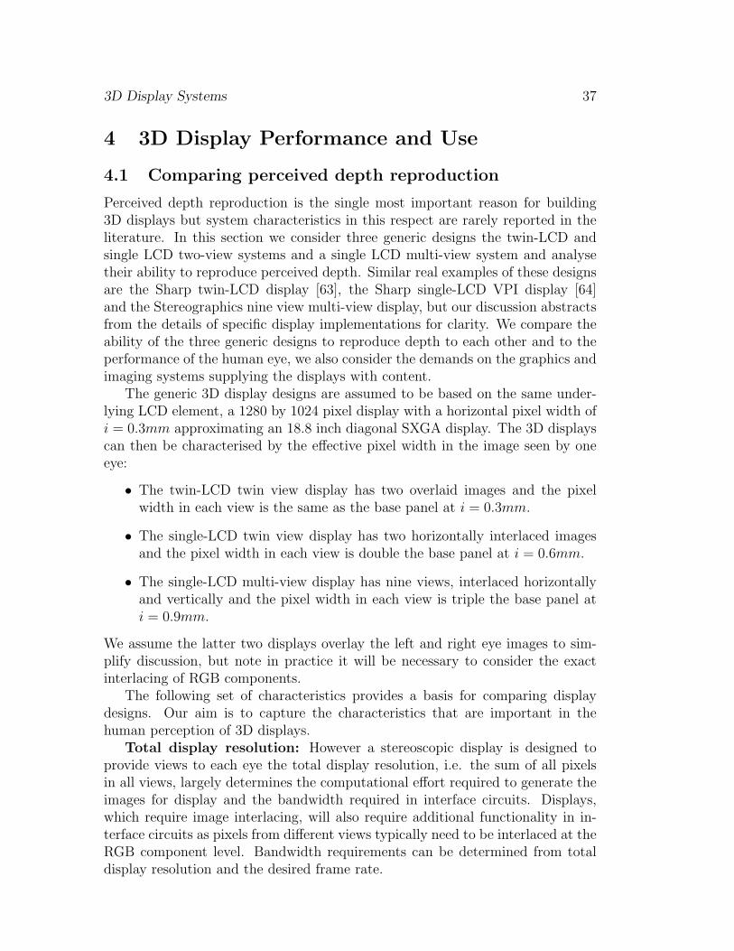
Perceived depth reproduction is the single most important reason for building3D displays but system characteristics in this respect are rarely reported in theliterature. In this section we consider three generic designs the twin-LCD andsingle LCD two-view systems and a single LCD multi-view system and analysetheir ability to reproduce perceived depth. Similar real examples of these designsare the Sharp twin-LCD display [63], the Sharp single-LCD VPI display [64]and the Stereographics nine view multi-view display, but our discussion abstractsfrom the details of specific display implementations for clarity. We compare theability of the three generic designs to reproduce depth to each other and to theperformance of the human eye, we also consider the demands on the graphics andimaging systems supplying the displays with content.
The generic 3D display designs are assumed to be based on the same under-lying LCD element, a 1280 by 1024 pixel display with a horizontal pixel width ofi = 0.3mm approximating an 18.8 inch diagonal SXGA display. The 3D displayscan then be characterised by the effective pixel width in the image seen by oneeye:
• The twin-LCD twin view display has two overlaid images and the pixelwidth in each view is the same as the base panel at i = 0.3mm.
• The single-LCD twin view display has two horizontally interlaced imagesand the pixel width in each view is double the base panel at i = 0.6mm.
• The single-LCD multi-view display has nine views, interlaced horizontallyand vertically and the pixel width in each view is triple the base panel ati = 0.9mm.
We assume the latter two displays overlay the left and right eye images to sim-plify discussion, but note in practice it will be necessary to consider the exactinterlacing of RGB components.
The following set of characteristics provides a basis for comparing displaydesigns. Our aim is to capture the characteristics that are important in thehuman perception of 3D displays.
Total display resolution: However a stereoscopic display is designed toprovide views to each eye the total display resolution, i.e. the sum of all pixelsin all views, largely determines the computational effort required to generate theimages for display and the bandwidth required in interface circuits. Displays,which require image interlacing, will also require additional functionality in in-terface circuits as pixels from different views typically need to be interlaced at theRGB component level. Bandwidth requirements can be determined from totaldisplay resolution and the desired frame rate.

3D Display Systems 38
Resolution per view: The resolution per view is a key characteristic of a 3Ddisplay. Having stereo 3D does not replace the need for high spatial resolutionand anyone used to 1280x1024 monoscopic displays will notice the step downwhen dividing these pixels between two or nine views. A 3D display can oftenlook better than a monoscopic display with the same resolution as a single viewon the 3D display because the brain integrates the information received from thetwo views into a single image.
L
R
L
R
Dis
pla
y
Z
E
Ob
serv
er
(a) Zero pixels disparity represents a
volume of perceived depth as overlapping
corresponding pixels have non-zero width.
1 2
Pixels
Pixels
1 2
(b) Two pixels disparity represents a
volume of perceived depth as shown.
E
Z
i
i
Typical values for the generic displays:
Pixel width, i = 0.3mm, 0.6mm or 0.9mm
Eye separation, E = 65mm
Viewing distance, Z=750mm
Figure 22: The perceived depth represented by corresponding pixels of 0 and 2pixels screen disparity.
Perceived depth voxels: As shown in figure 22 a pair of correspondingpixels in the left and right images represent a volume of perceived depth, wewill call this a stereoscopic voxel or voxel as in [24]. Of particular interest is thedepth of a voxel that a display can represent for a given screen disparity betweencorresponding pixels. We can use this to compare the depth representation abil-ities of different displays in depth and to compare displays with the ability ofthe eye to perceive depth. The perceived voxels are arranged in planes from infront to behind the display as they recede from the viewer the cells increase indepth[8, 24].
The depth span of a voxel can be found by using equations (10) and (11) as

3D Display Systems 39
appropriate to calculate difference in depth of points 1 and 2 in figure 22.Considering zero pixels disparity as in figure 22(a). For point 1, a pixel width
i = 0.3mm implies screen disparity of d = −0.3mm and assuming z = 750mmand e = 65mm then the perceived depth in front of the screen plane is:
p =750(
65|−0.3|
)+ 1
= 3.45mm (23)
For point 2 the screen disparity is d = 0.3mm and the perceived depth behindthe screen plane is:
p =750(
65|0.3|
)− 1
= 3.48mm (24)
Therefore the total perceived voxel depth in this case is 6.93mm. This isthe perceived depth represented by corresponding pixels with zero disparity atthe screen plane. In practice it tells us this display cannot reproduce a depthdifference between objects at the screen plane of less the 6.93mm. Results ofsimilar calculations for all three generic displays are given in figure 24.
Perceived depth range: The perceived depth range, that is the nearestand furthest points a display can reproduce, is of interest. Geometrically this canbe calculated from the maximum screen disparity available, however for mostdisplays of any size the geometric range is much more than can be viewed com-fortably by the majority of observers. Instead it is important to determine thecomfortable perceived depth range experimentally and for our discussion we adoptresults reported in [27]. This suggests a comfortable working range for the ma-jority of people is from 100mm in front to 100mm behind the display surface andthis range could probably be extended to 200mm in front and 500mm behind andstill be comfortable to view for the majority of observers. We take the +/-100mmrange for our calculations here without affecting the generality of the discussion.
Stereoscopic resolution: Identifying the comfortable working range of per-ceived depth on a display also allows us to define the resolution of perceived depthwithin this range. Perceived depth voxels of equal screen disparity form planesof voxels parallel to the display surface as illustrated in figure 23. We will definestereoscopic resolution to be the number of planes of voxels within the range of+/-100mm.
Stereoscopic resolution can be calculated identically for each of the genericdisplays, which have the same viewing distance, by finding the screen disparity,d, that generates voxels at +/-100mm. The sum of these values is then dividedby the width of a stereoscopic pixel, i, on the display in question.
The table in figure 24 shows values of the characteristics discussed here forthe three generic displays. Not surprisingly the twin-LCD display with the mostpixels per view has the best results for depth reproduction with an ability toreproduce depth differences of 7mm at the screen plane and a stereoscopic res-olution of 60 planes of depth in the working depth range +/-100mm. However

3D Display Systems 40
Display
Right
Eye
Left
Eye
e
z
0 -1 -3-4-212345
Value of image disparity in pixels
Figure 23: Stereoscopic resolution is defined by planes of stereoscopic voxels.
Twin-LCD
Twin View
2x
1280(h)x1024(v)
1280(h)x1024(v)
0.3mm
750mm
7mm
60 voxels
Characteristic
Total resolution
View resolution
View pixel width
Viewing distance
Voxel depth:
0 pixels disparity
Stereo resolution
(in +/-100mm)
Single-LCD
Twin View
1280(h)x1024(v)
640(h)x1024(v)
0.6mm
750mm
14mm
31 voxels
Single-LCD
Multi (9) View
1280(h)x1024(v)
426(h)x341(v)
0.9mm
750mm
21mm
20 voxels
Human Vision
0.84mm
~240 voxels
The calculations for this table assume an observer eye separation of 65mm.
Figure 24: Table comparing characteristics of the generic displays and the eye.

3D Display Systems 41
the eye is much better at perceiving depth than the best display is at reproduc-ing it with a minimum detectable depth difference of 0.84mm and an equivalentstereoscopic resolution of 240 planes of depth in the working range +/- 100mm.
This difference suggests significant improvements are still possible to the depthreproduction characteristics of stereoscopic displays. It is also important to keepin mind when using the displays if depth judgement is critical to task performance.In the next section we briefly review how to create images that account for theavailable working depth range and resolution of 3D displays.
4.2 Perceived depth control and image generation
As discussed 3D displays have limits on the comfortable perceived depth rangethey can reproduce. This results in a working volume of space around the displayplane that content producers can use to present a scene in. The working volumeavailable on the display is unlikely to match the volume in the scene being cap-tured. As a result several approaches to mapping depth from a scene onto theavailable depth range of the target display have been proposed.
Traditionally this has involved a discussion of whether to set cameras at eyeseparation or not and whether camera axis should be parallel or verging. How-ever recent methods approach the problem as a mapping of a volume of scenespace onto the available working volume on the target display. These methodsautomatically calculate stereoscopic camera parameters given a camera position,scene volume to capture and target display specifications. Wartell describes oneapproach in [60] while a simpler and more general method is given in Jones [27].These have significant benefits in ease of image generation for content creatorsand guarantee that depth mappings will be geometrically consistent even on headtracked displays. The result is stereoscopic images should no longer be producedwith excessive perceived depth or unwanted distortions.
Despite the long history of stereo image generation it is only recently that newtechnology, in the form of 3D computer graphics and digital camera technology,has been able to give enough control over the image creation process to use thesemethods. The methods are particularly important to apply when creating imagesfor testing and improving a display design since poorly created images, or evenjust images produced correctly for a different 3D display can cause the highestquality display to become uncomfortable to view.
3D Display Systems 42
5 Summary
Advances in micro-optics, display technologies and computing systems are com-bining to produce an exciting range of new opportunities for 3D display designers.To achieve a good 3D display design requires a systems approach combining opti-cal, electrical, mechanical and digital imaging skills along with an understandingof the mechanism of binocular vision.
The characteristics and geometry of binocular vision define limits on the max-imum range of binocular vision and the minimum depth differences it is possibleto perceive in the natural world. Because the perception of depth is relative tothe current fixation point binocular vision is best suited to making relative depthjudgements between objects.
Stereoscopic images do not provide the same stimulus to the eyes as thenatural world and the implications of this affects 3D display design and use.In particular while the eyes verge to fixate different depths in a stereo imagethe eye’s accommodation must keep the image plane, rather than the fixationpoint, in focus. This places measurable limits on how much perceived depth iscomfortable to view on a particular 3D display.
As well as the stereoscopic depth cue the brain uses many 2D depth cues tohelp it understand depth information in a scene. Therefore the first aim for a 3Ddisplay design needs to be to keep the same basic image quality as a 2D displayincluding values of brightness, contrast, spatial resolution and viewing freedom.
We have introduced two-view and multi-view autostereoscopic display de-signs based on micro-optic elements including: parallax barriers, lenticular ar-rays, micro-polarisers and holographic optical elements. These provide differenttradeoffs in cost, system complexity and performance. Key characteristics thatdefine the performance of different displays include:
• Perceived voxel depth at zero disparity, i.e. minimum reproducible depthat the screen plane.
• Stereoscopic resolution, i.e. the number of discrete voxel planes in +/-100mm depth.
• Viewing window characteristics particularly inter-channel crosstalk and uni-formity.
As 3D display quality continues to improve it becomes increasingly importantto consider the quality of the stereoscopic images used to evaluate displays. Thisrequires the adoption of new methods for image generation based on an improvedunderstanding of the human perception of stereo images to define the mappingof depth from a scene onto the working depth range available on the 3D display.

3D Display Systems 43
References[1] S.A. Benton, T.E. Slowe, A.B. Kropp and S.L. Smith Micropolarizer-based multiple-viewer autostereoscopic display. Pro-
ceedings of the SPIE, Vol.3639, January 1999
[2] S.A. Benton Autostereoscopic display system. US 6351280, February 2002 (Filed November 1998).
[3] C. Blakemore. The range and scope of binocluar depth discrimination in man. Physiology, Vol. 211:599-622, 1970.
[4] R. Borner Autostereoscopic 3D-imaging by front and rear projection on flat panel displays. Displays, Vol.14, No. 1, 1993.
[5] B.G. Cumming and G.C. DeAngelis. The physiology of stereopsis. Annu. Rev. Neurosci., (24):203-238, 2001.
[6] N. Dodgson Autostereo displays: 3D without glasses Proceedings of the EID, EID97, 1997.
[7] N.A. Dodgson Analysis of the viewing zome of multi-view autostereoscopic displays. Proceedings of the SPIE, Vol.4660,January 2002.
[8] D.B. Diner and D.H. Fender Human Engineering in Stereoscopic Display Devices Plenum Press, 1993.
[9] J. Eichenlaub A compact, lightweight, 2D/3D autostereoscopic backlight for games, monitor and notebook applications. Proceed-ings of the SPIE, Vol. 3012, 1997.
[10] J. Eichenlaub A compact, lightweight, 2D/3D autostereoscopic backlight for games, monitor and notebook applications. Pro-ceedings of the SPIE, Vol. 3295, 1998.
[11] J. Eichenlaub, R. Gruhlke Reduced thickness backlighter for autostereoscopic display and display using the backlighter.US Pat. No. 5,897,184
[12] D.Ezra, G.Woodgate, J.Harrold, B.Omar, N.Holliman and L. Shaprio New Auto-stereoscopic display system Proceedings ofthe SPIE, Vol. 2409, 1995.
[13] D. Ezra, G.J. Woodgate and B. Omar Autostereoscopic Directional Display Aparatus US pat. 5,726,800, March 10th 1998(priority from December 17th 1992)
[14] S.M. Faris Novel 3D-stereoscopic imaging technology Proceedings of the SPIE, Vol. 2177, 1994.
[15] S.M. Faris Multi-mode stereoscopic imaging system. US 5264964, November 1993.
[16] A. Glassner Principles of digital image synthesis. Morgan Kaufmann, 1995.
[17] L. Gooding, M.E. Miller, J. Moore, S. Kim. The effect of viewing distance and disparity on perceived depth. Proceedings ofthe SPIE, Vol. 1457, 1991.
[18] E.B. Goldstein Sensation and Perception sixth edition, published by Wadsworth, 2002.
[19] G. Hamagishi, M. Sakata, A. Yamashita, K. Mashitani, M. Inoue, E. Shimizu 15” high resolution non-glasses 3-D displaywith head-tracking system. Transaction of IEE, Japan, Vol.121-C, No.5, May 2001.
[20] J. Harrold, A.M.S. Jacobs, G.J. Woodgate, D. Ezra 3D display systems hardware research at Sharp Laboratories of Europe:an update Sharp Technical J., 1999, no 8.
[21] J. Harrold, A. Jacobs, G.J. Woodgate and D. Ezra Performance of a convertible, 2D and 3D parallax barrier autostereoscopicdisplay. Proceedings of the SID, 20th International Display Research Conference, September 2000, Palm Beach Florida USA.
[22] T. Hattori, T. Ishigaki, K. Shimamoto, A. Sawaki, T. Ishiguchi, H. Kobayashi An advanced autostereoscopic display forG7 pilot project. Proceedings of the SPIE, Vol. 3639, 1999.
[23] H. Helmholtz. Treatise on physiological optics 1867, 1924 edition reprinted Thoemmes Press, 2000
[24] L.F. Hodges, E.T. Davis Geometric Considerations for Stereoscopic Virtual Environments. Presence, Vol. 2, No. 1, Winter1993.
[25] Image tracking system and method and observer tracking autostereoscopic display N. Holliman, Q. Hong, G. Woodgate,D. Ezra US Pat. No. 6,075,557, June 2000.
[26] M. Inoue, G. Hamagishi, M. Sakata, A. Yamashita, K. Mahitani. Non-glasses 3-D displays by shift- image splitter technology.Proceedings 3D Image Conference 2000, Tokyo, Japan, July 2000.
[27] G. Jones, D. Lee, N. Holliman, D. Ezra. Controlling perceived depth in stereoscopic images. Proceedings of the SPIE, Vol.4297A, 2001.
[28] B. Julesz Foundations of cyclopean perception The University of Chicago Press, 1971.
[29] S. Kaplan Theory of parallax barriers Journal of the SMPTE, Vol 59, July 1952.
[30] B. Lane Stereoscopic displays Proceedings of the SPIE, Vol. 0367, Aug. 1982.

3D Display Systems 44
[31] N. Langlands Experiments on binocular vision. Trans. Optical Soc., Vol.XXVII No.2:4-82, 1926.
[32] J. Lipscomb and W. Wotton Reducing crosstalk between stereoscopic views. Proceedings of the SPIE, Vol. 2177, 1993.
[33] L. Lipton Foundations of stereoscopic cinema. Van Nostrand Reinhold, 1982, now available electronically.
[34] L. Lipton Synthagram: autostereoscopic display technology. Proceedings of the SPIE, Vol. 4660, 2002.
[35] D.F. McAllister Stereo computer graphics and other true 3D technologies. Princeton University Press, 1993.
[36] D.J. Montgomery, G.J. Woodgate, D. Ezra Parallax barrier for an autostereoscopic display. Patent no. GB 2352573, January2001.
[37] J. Moore, N. Dodgson, A. Travis and S. Lang. Time-multiplexed color autostereoscopic display. Proceedings of the SPIEvol 2653, Jan 1996.
[38] H. Morishima, H. Nose, N. Taniguchi Stereoscopic image display apparatus. US Pat No. 6,160,527
[39] H. Nose Rear-lenticular 3D-LCD without eyeglasses O plus E, no.217, pp.105-109, Dec. 1997.
[40] K.N. Ogle. Researches in Binocular Vision. Hafner Publishing Co. Ltd, 1964.
[41] T. Okoshi Three-dimensional imaging techniques. Academic Press, New York, 1976.
[42] S. Pastoor 3D-television: a survey of recent research results on subjective requirements. Signal Processing: Image Com-munication, Vol. 4, 1991.
[43] S. Pastoor Human Factors of 3D Imaging Web document distributed by Heinrich-Hertz-Institut, Berlin, 1995
[44] S. Pastoor and M. Wopking 3-D displays: a review of current technologies. Displays 17, 1997.
[45] K. Perlin, S. Paxia, J.S.Kollin An autostereoscopic display Proceedings ACM Siggraph Conference, July 2000.
[46] K. Perlin Displayer and method for displaying US 6239830, May 2001, (filed May 1999)
[47] K. Perlin, C. Poultney, J.S. Kollin, D.T. Kristjansson, S. Paxia Recent advances in the NYU autostereoscopic display.Proceedings of the SPIE, Vol. 4297, 2001.
[48] W. Richards Stereopsis and Stereoblindness Exp. Brian Res. 10, 380-388, 1970.
[49] H.R. Schiffman Sensation and Perception: An Integrated Approach, 5th edition. Wiley, October 2000, ISBN:0-471-24930-0.
[50] A. Schwerdtner, H. Heidrich The Dresden 3D Display (D4D) Proceedings of the SPIE, Vol. 3295, 1998.
[51] A. Schwerdtner, H. Heidrich Optical System for the Two and Three Dimensional Representation of Information. US Pat.No. 5,774,262, June 1998 (filed Germany 1993).
[52] I. Susumu, T. Nobuji and I. Morito Technique of stereoscopic image display EP Pat. No. 0 354 851, June 1990 (filed JapanAugust 1988).
[53] D. Trayner, E. Orr Developments in Autostereoscopic Displays using Holographic Optical Elements Proceedings of the SPIE,Vol. 3012, 1997.
[54] D. Trayner, E. Orr Direct View Holographic Autostereoscopic Displays Proceedings of the Fourth UK VR-SIG, BrunelUnivesity, November 1997.
[55] N.A. Valyus. Stereoscopy The Focal Press, 1966.
[56] C. van Berkel, D.W. Parker, A.R. Franklin Multi-view LCD Proc SPIE Vol. 2653, 1996
[57] C. vanBerkel and J.A. Clarke Characterisation and Optimisation of 3D-LCD Module Design Proc SPIE Vol. 3012, 1997
[58] C. van Berkel, J. Clarke Autostereoscopic display apparatus. US Pat. No. 6,064,424, May 2000.
[59] C. van Berkel, D. Parker Autostereoscopic display apparatus. US Pat. No. 6,118,584, Sep. 2000.
[60] Z. Wartell, L.F. Hodges, W. Ribarsky. Balancing fusion, image depth and distortion in stereoscopic head tracked displays.Computer Graphics, Proc. ACM Siggraph99, 1999.
[61] D.F. Winnek Composite stereography. U.S. Pat. No. 3,409,351, issued Nov. 5, 1968.
[62] C. Wheatstone. Contributions to the physiology of vision I: On some remarkable and hitherto unobserved phenomena ofvision. Phil Trans R Soc (Biol), 18(13):371-395, 1838.

3D Display Systems 45
[63] G. Woodgate, D. Ezra, J. Harrold, N. Holliman, G. Jones and R. Moseley. Observer tracking autostereoscopic 3D displaysystems. Proceedings of the SPIE, Vol. 3012, 1997.
[64] G. Woodgate, J. Harrold, M. Jacobs, R. Moseley and D. Ezra. Flat panel autostereoscopic displays - characterisation andenhancement. Proceedings of the SPIE, Vol. 3957, 2000.
[65] G.Woodgate, R. Moseley, D. Ezra and N. Holliman. Autosterescopic Display US Pat. No. 6.055.013, April 2000, priorityFeb. 1997.
[66] A. Woods, T. Docherty, R. Koch. Image distortions in stereoscopic video systems. Proceedings of the SPIE, Vol. 1915:36-48,1993
[67] Y. Yeh and L.D. Silverstein Limits of fusion and depth judgement in stereoscopic colour displays Human Factors, V32n1,pp45-60, 1990.
[68] Y. Yeh Visual and perceptual issues in stereoscopic colour displays. In ”Stereo computer graphics and other true 3Dtechnologies”, Ed. D. McAllister, Princeton University Press, 1993.