3500 galvanic isolator interface...3500 galvanic isolator interface the 3500 galvanic isolator...
TRANSCRIPT
Specifications and Ordering Information Part Number 141714-01
Rev. H (06/15)
Page 1 of 17
Bently Nevada* Asset Condition Monitoring
3500 Galvanic Isolator Interface
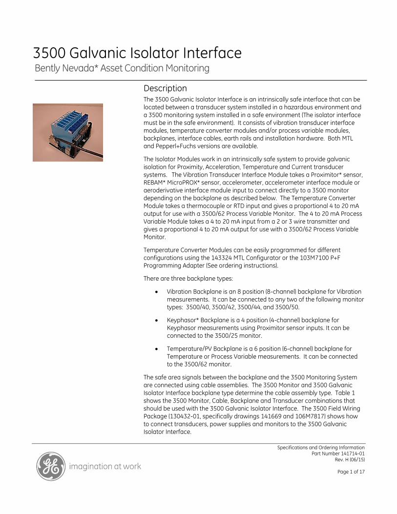
Description The 3500 Galvanic Isolator Interface is an intrinsically safe interface that can be
located between a transducer system installed in a hazardous environment and
a 3500 monitoring system installed in a safe environment (The isolator interface
must be in the safe environment). It consists of vibration transducer interface
modules, temperature converter modules and/or process variable modules,
backplanes, interface cables, earth rails and installation hardware. Both MTL and Pepperl+Fuchs versions are available.
The Isolator Modules work in an intrinsically safe system to provide galvanic
isolation for Proximity, Acceleration, Temperature and Current transducer
systems. The Vibration Transducer Interface Module takes a Proximitor* sensor,
REBAM* MicroPROX* sensor, accelerometer, accelerometer interface module or
aeroderivative interface module input to connect directly to a 3500 monitor
depending on the backplane as described below. The Temperature Converter
Module takes a thermocouple or RTD input and gives a proportional 4 to 20 mA
output for use with a 3500/62 Process Variable Monitor. The 4 to 20 mA Process
Variable Module takes a 4 to 20 mA input from a 2 or 3 wire transmitter and
gives a proportional 4 to 20 mA output for use with a 3500/62 Process Variable Monitor.
Temperature Converter Modules can be easily programmed for different
configurations using the 143324 MTL Configurator or the 103M7100 P+F Programming Adapter (See ordering instructions).
There are three backplane types:
Vibration Backplane is an 8 position (8-channel) backplane for Vibration
measurements. It can be connected to any two of the following monitor types: 3500/40, 3500/42, 3500/44, and 3500/50.
Keyphasor* Backplane is a 4 position (4-channel) backplane for
Keyphasor measurements using Proximitor sensor inputs. It can be connected to the 3500/25 monitor.
Temperature/PV Backplane is a 6 position (6-channel) backplane for
Temperature or Process Variable measurements. It can be connected to the 3500/62 monitor.
The safe area signals between the backplane and the 3500 Monitoring System
are connected using cable assemblies. The 3500 Monitor and 3500 Galvanic
Isolator Interface backplane type determine the cable assembly type. Table 1
shows the 3500 Monitor, Cable, Backplane and Transducer combinations that
should be used with the 3500 Galvanic Isolator Interface. The 3500 Field Wiring
Package (130432-01, specifically drawings 141669 and 106M7817) shows how
to connect transducers, power supplies and monitors to the 3500 Galvanic Isolator Interface.
Specifications and Ordering Information Part Number 141714-01
Rev. H (06/15)
Page 2 of 17
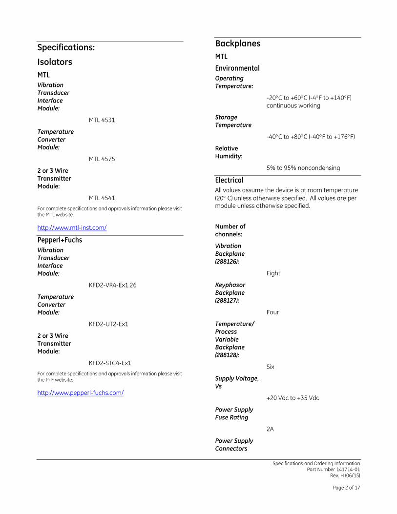
Specifications:
Isolators
MTL
Vibration
Transducer
Interface
Module:
MTL 4531
Temperature
Converter
Module:
MTL 4575
2 or 3 Wire
Transmitter
Module:
MTL 4541
For complete specifications and approvals information please visit the MTL website:
http://www.mtl-inst.com/
Pepperl+Fuchs
Vibration
Transducer
Interface
Module:
KFD2-VR4-Ex1.26
Temperature
Converter
Module:
KFD2-UT2-Ex1
2 or 3 Wire
Transmitter
Module:
KFD2-STC4-Ex1
For complete specifications and approvals information please visit the P+F website:
http://www.pepperl-fuchs.com/
Backplanes
MTL
Environmental
Operating
Temperature:
-20C to +60C (-4F to +140F)
continuous working
Storage
Temperature
-40C to +80C (-40F to +176F)
Relative
Humidity:
5% to 95% noncondensing
Electrical
All values assume the device is at room temperature
(20 C) unless otherwise specified. All values are per module unless otherwise specified.
Number of
channels:
Vibration
Backplane
(288126):
Eight
Keyphasor
Backplane
(288127):
Four
Temperature/
Process
Variable
Backplane
(288128):
Six
Supply Voltage,
Vs
+20 Vdc to +35 Vdc
Power Supply
Fuse Rating
2A
Power Supply
Connectors
Specifications and Ordering Information Part Number 141714-01
Rev. H (06/15)
Page 3 of 17
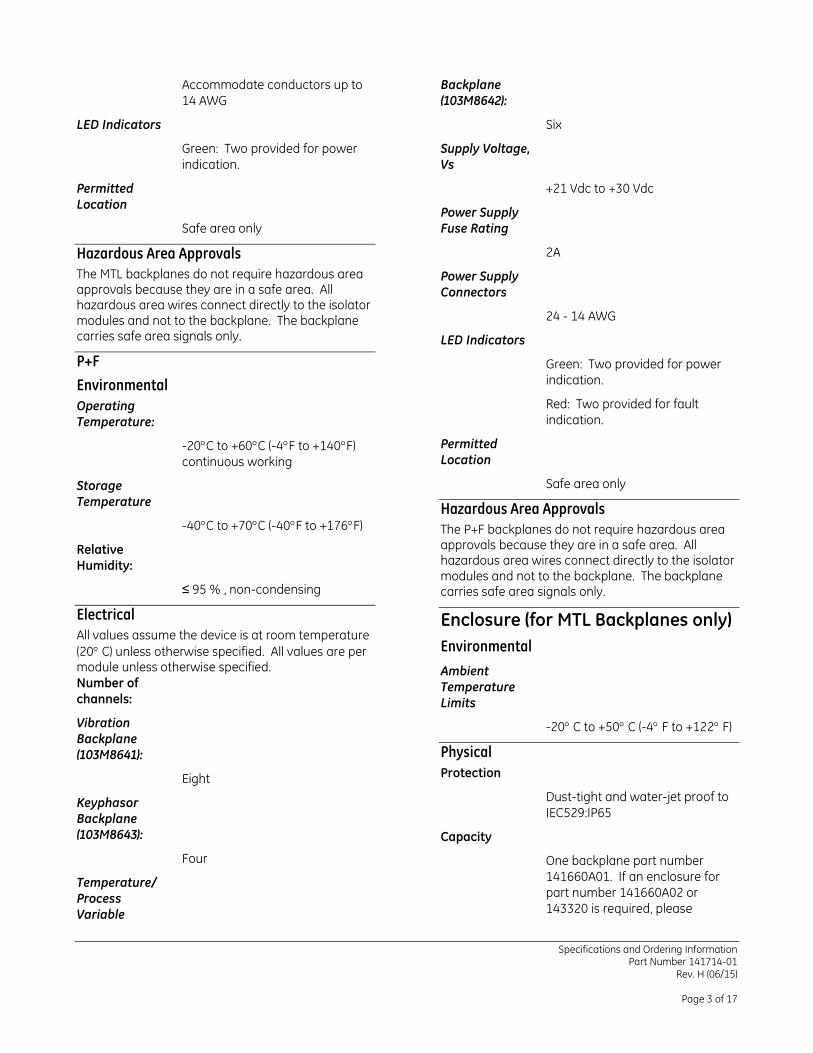
Accommodate conductors up to
14 AWG
LED Indicators
Green: Two provided for power
indication.
Permitted
Location
Safe area only
Hazardous Area Approvals
The MTL backplanes do not require hazardous area approvals because they are in a safe area. All hazardous area wires connect directly to the isolator modules and not to the backplane. The backplane carries safe area signals only.
P+F
Environmental
Operating
Temperature:
-20C to +60C (-4F to +140F)
continuous working
Storage
Temperature
-40C to +70C (-40F to +176F)
Relative
Humidity:
≤ 95 % , non-condensing
Electrical
All values assume the device is at room temperature
(20 C) unless otherwise specified. All values are per module unless otherwise specified.
Number of
channels:
Vibration
Backplane
(103M8641):
Eight
Keyphasor
Backplane
(103M8643):
Four
Temperature/
Process
Variable
Backplane
(103M8642):
Six
Supply Voltage,
Vs
+21 Vdc to +30 Vdc
Power Supply
Fuse Rating
2A
Power Supply
Connectors
24 - 14 AWG
LED Indicators
Green: Two provided for power
indication.
Red: Two provided for fault
indication.
Permitted
Location
Safe area only
Hazardous Area Approvals
The P+F backplanes do not require hazardous area approvals because they are in a safe area. All hazardous area wires connect directly to the isolator modules and not to the backplane. The backplane carries safe area signals only.
Enclosure (for MTL Backplanes only)
Environmental
Ambient
Temperature
Limits
-20 C to +50 C (-4 F to +122 F)
Physical
Protection
Dust-tight and water-jet proof to
IEC529:IP65
Capacity
One backplane part number
141660A01. If an enclosure for
part number 141660A02 or
143320 is required, please
Specifications and Ordering Information Part Number 141714-01
Rev. H (06/15)
Page 4 of 17
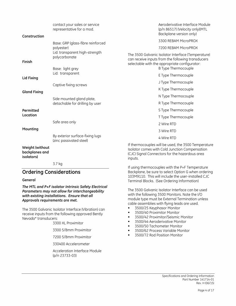
contact your sales or service
representative for a mod.
Construction
Base: GRP (glass-fibre reinforced
polyester)
Lid: transparent high-strength
polycarbonate
Finish
Base: light grey
Lid: transparent
Lid Fixing
Captive fixing screws
Gland Fixing
Side mounted gland plate,
detachable for drilling by user
Permitted
Location
Safe area only
Mounting
By exterior surface-fixing lugs
(zinc passivated steel)
Weight (without
backplanes and
isolators)
3.7 kg
Ordering Considerations
General
The MTL and P+F isolator Intrinsic Safety Electrical Parameters may not allow for interchangeability with existing installations. Ensure that all Approvals requirements are met.
The 3500 Galvanic Isolator Interface (Vibration) can receive inputs from the following approved Bently Nevada* transducers:
3300 XL Proximitor
3300 5/8mm Proximitor
7200 5/8mm Proximitor
330400 Accelerometer
Acceleration Interface Module
(p/n 23733-03)
Aeroderivative Interface Module
(p/n 86517) (Velocity only)(MTL
Backplane version only)
3300 REBAM MicroPROX
7200 REBAM MicroPROX
The 3500 Galvanic Isolator Interface (Temperature) can receive inputs from the following transducers selectable with the appropriate configurator:
B Type Thermocouple
E Type Thermocouple
J Type Thermocouple
K Type Thermocouple
N Type Thermocouple
R Type Thermocouple
S Type Thermocouple
T Type Thermocouple
2 Wire RTD
3 Wire RTD
4 Wire RTD
If thermocouples will be used, the 3500 Temperature Isolator comes with Cold Junction Compensation (CJC) Signal Connectors for the hazardous area inputs. If using thermocouples with the P+F Temperature Backplane, be sure to select Option G when ordering 103M9110. This will include the user-installed CJC Terminal Blocks. (See Ordering Information) The 3500 Galvanic Isolator Interface can be used with the following 3500 Monitors. Note the I/O module type must be External Termination unless cable assemblies with flying leads are used. 3500/25 Keyphasor Monitor 3500/40 Proximitor Monitor 3500/42 Proximitor/Seismic Monitor 3500/44 Aeroderivative Monitor 3500/50 Tachometer Monitor 3500/62 Process Variable Monitor 3500/72 Rod Position Monitor
Specifications and Ordering Information Part Number 141714-01
Rev. H (06/15)
Page 5 of 17
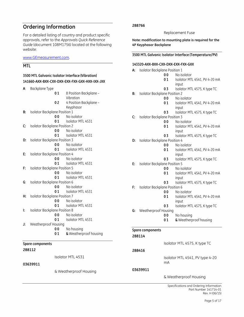
Ordering Information
For a detailed listing of country and product specific
approvals, refer to the Approvals Quick Reference
Guide (document 108M1756) located at the following website:
www.GEmeasurement.com.
MTL
3500 MTL Galvanic Isolator Interface (Vibration)
141660-AXX-BXX-CXX-DXX-EXX-FXX-GXX-HXX-IXX-JXX
A: Backplane Type 0 1 8 Position Backplane –
Vibration 0 2 4 Position Backplane –
Keyphasor B: Isolator Backplane Position 1
0 0 No isolator 0 1 Isolator MTL 4531
C: Isolator Backplane Position 2 0 0 No isolator 0 1 Isolator MTL 4531
D: Isolator Backplane Position 3 0 0 No isolator 0 1 Isolator MTL 4531
E: Isolator Backplane Position 4 0 0 No isolator 0 1 Isolator MTL 4531
F: Isolator Backplane Position 5 0 0 No isolator 0 1 Isolator MTL 4531
G: Isolator Backplane Position 6 0 0 No isolator 0 1 Isolator MTL 4531
H: Isolator Backplane Position 7 0 0 No isolator 0 1 Isolator MTL 4531
I: Isolator Backplane Position 8 0 0 No isolator 0 1 Isolator MTL 4531
J: Weatherproof Housing 0 0 No housing 0 1 & Weatherproof housing
Spare components
288112
Isolator MTL 4531
03639911
& Weatherproof Housing
288766
Replacement Fuse
Note: modification to mounting plate is required for the
4P Keyphasor Backplane
3500 MTL Galvanic Isolator Interface (Temperature/PV)
143320-AXX-BXX-CXX-DXX-EXX-FXX-GXX
A: Isolator Backplane Position 1 0 0 No isolator 0 1 Isolator MTL 4541, PV 4-20 mA
input 0 3 Isolator MTL 4575, K type TC
B: Isolator Backplane Position 2 0 0 No isolator 0 1 Isolator MTL 4541, PV 4-20 mA
input 0 3 Isolator MTL 4575, K type TC
C: Isolator Backplane Position 3 0 0 No isolator 0 1 Isolator MTL 4541, PV 4-20 mA
input 0 3 Isolator MTL 4575, K type TC
D: Isolator Backplane Position 4 0 0 No isolator 0 1 Isolator MTL 4541, PV 4-20 mA
input 0 3 Isolator MTL 4575, K type TC
E: Isolator Backplane Position 5 0 0 No isolator 0 1 Isolator MTL 4541, PV 4-20 mA
input 0 3 Isolator MTL 4575, K type TC
F: Isolator Backplane Position 6 0 0 No isolator 0 1 Isolator MTL 4541, PV 4-20 mA
input 0 3 Isolator MTL 4575, K type TC
G: Weatherproof Housing 0 0 No housing 0 1 & Weatherproof housing
Spare components
288114
Isolator MTL 4575, K type TC
288416
Isolator MTL 4541, PV type 4-20
mA
03639911
& Weatherproof Housing
Specifications and Ordering Information Part Number 141714-01
Rev. H (06/15)
Page 6 of 17
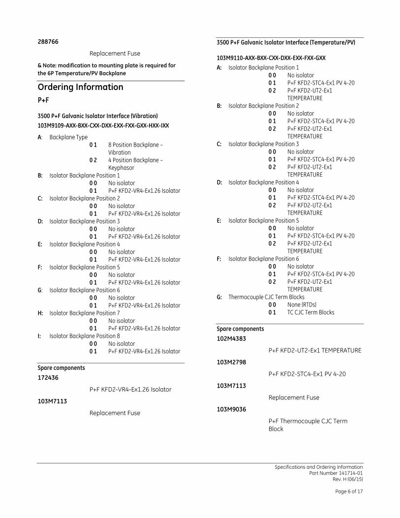
288766
Replacement Fuse
& Note: modification to mounting plate is required for
the 6P Temperature/PV Backplane
Ordering Information
P+F
3500 P+F Galvanic Isolator Interface (Vibration)
103M9109-AXX-BXX-CXX-DXX-EXX-FXX-GXX-HXX-IXX
A: Backplane Type 0 1 8 Position Backplane –
Vibration 0 2 4 Position Backplane –
Keyphasor B: Isolator Backplane Position 1
0 0 No isolator 0 1 P+F KFD2-VR4-Ex1.26 Isolator
C: Isolator Backplane Position 2 0 0 No isolator 0 1 P+F KFD2-VR4-Ex1.26 Isolator
D: Isolator Backplane Position 3 0 0 No isolator 0 1 P+F KFD2-VR4-Ex1.26 Isolator
E: Isolator Backplane Position 4 0 0 No isolator 0 1 P+F KFD2-VR4-Ex1.26 Isolator
F: Isolator Backplane Position 5 0 0 No isolator 0 1 P+F KFD2-VR4-Ex1.26 Isolator
G: Isolator Backplane Position 6 0 0 No isolator 0 1 P+F KFD2-VR4-Ex1.26 Isolator
H: Isolator Backplane Position 7 0 0 No isolator 0 1 P+F KFD2-VR4-Ex1.26 Isolator
I: Isolator Backplane Position 8 0 0 No isolator 0 1 P+F KFD2-VR4-Ex1.26 Isolator
Spare components
172436
P+F KFD2-VR4-Ex1.26 Isolator
103M7113
Replacement Fuse
3500 P+F Galvanic Isolator Interface (Temperature/PV)
103M9110-AXX-BXX-CXX-DXX-EXX-FXX-GXX
A: Isolator Backplane Position 1 0 0 No isolator 0 1 P+F KFD2-STC4-Ex1 PV 4-20 0 2 P+F KFD2-UT2-Ex1
TEMPERATURE B: Isolator Backplane Position 2
0 0 No isolator 0 1 P+F KFD2-STC4-Ex1 PV 4-20 0 2 P+F KFD2-UT2-Ex1
TEMPERATURE C: Isolator Backplane Position 3
0 0 No isolator 0 1 P+F KFD2-STC4-Ex1 PV 4-20 0 2 P+F KFD2-UT2-Ex1
TEMPERATURE D: Isolator Backplane Position 4
0 0 No isolator 0 1 P+F KFD2-STC4-Ex1 PV 4-20 0 2 P+F KFD2-UT2-Ex1
TEMPERATURE E: Isolator Backplane Position 5
0 0 No isolator 0 1 P+F KFD2-STC4-Ex1 PV 4-20 0 2 P+F KFD2-UT2-Ex1
TEMPERATURE F: Isolator Backplane Position 6
0 0 No isolator 0 1 P+F KFD2-STC4-Ex1 PV 4-20 0 2 P+F KFD2-UT2-Ex1
TEMPERATURE G: Thermocouple CJC Term Blocks
0 0 None (RTDs) 0 1 TC CJC Term Blocks
Spare components
102M4383
P+F KFD2-UT2-Ex1 TEMPERATURE
103M2798
P+F KFD2-STC4-Ex1 PV 4-20
103M7113
Replacement Fuse
103M9036
P+F Thermocouple CJC Term
Block
Specifications and Ordering Information Part Number 141714-01
Rev. H (06/15)
Page 7 of 17
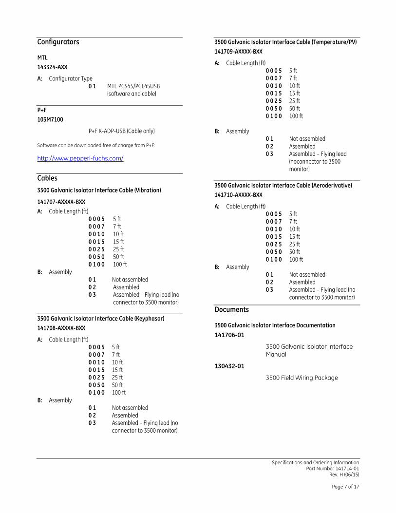
Configurators
MTL
143324-AXX
A: Configurator Type 0 1 MTL PCS45/PCL45USB
(software and cable)
P+F
103M7100
P+F K-ADP-USB (Cable only)
Software can be downloaded free of charge from P+F:
http://www.pepperl-fuchs.com/
Cables
3500 Galvanic Isolator Interface Cable (Vibration)
141707-AXXXX-BXX
A: Cable Length (ft) 0 0 0 5 5 ft 0 0 0 7 7 ft 0 0 1 0 10 ft 0 0 1 5 15 ft 0 0 2 5 25 ft 0 0 5 0 50 ft 0 1 0 0 100 ft
B: Assembly 0 1 Not assembled 0 2 Assembled 0 3 Assembled – Flying lead (no
connector to 3500 monitor)
3500 Galvanic Isolator Interface Cable (Keyphasor)
141708-AXXXX-BXX
A: Cable Length (ft) 0 0 0 5 5 ft 0 0 0 7 7 ft 0 0 1 0 10 ft 0 0 1 5 15 ft 0 0 2 5 25 ft 0 0 5 0 50 ft 0 1 0 0 100 ft
B: Assembly 0 1 Not assembled 0 2 Assembled 0 3 Assembled – Flying lead (no
connector to 3500 monitor)
3500 Galvanic Isolator Interface Cable (Temperature/PV)
141709-AXXXX-BXX
A: Cable Length (ft) 0 0 0 5 5 ft 0 0 0 7 7 ft 0 0 1 0 10 ft 0 0 1 5 15 ft 0 0 2 5 25 ft 0 0 5 0 50 ft 0 1 0 0 100 ft
B: Assembly 0 1 Not assembled 0 2 Assembled 0 3 Assembled – Flying lead
(noconnector to 3500 monitor)
3500 Galvanic Isolator Interface Cable (Aeroderivative)
141710-AXXXX-BXX
A: Cable Length (ft) 0 0 0 5 5 ft 0 0 0 7 7 ft 0 0 1 0 10 ft 0 0 1 5 15 ft 0 0 2 5 25 ft 0 0 5 0 50 ft 0 1 0 0 100 ft
B: Assembly 0 1 Not assembled 0 2 Assembled 0 3 Assembled – Flying lead (no
connector to 3500 monitor)
Documents
3500 Galvanic Isolator Interface Documentation
141706-01
3500 Galvanic Isolator Interface
Manual
130432-01
3500 Field Wiring Package
Specifications and Ordering Information Part Number 141714-01
Rev. H (06/15)
Page 8 of 17
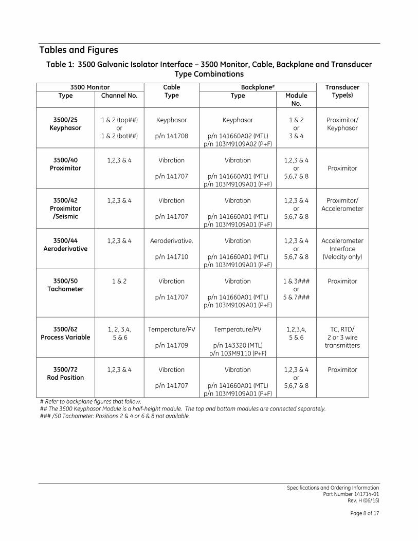
Tables and Figures
Table 1: 3500 Galvanic Isolator Interface – 3500 Monitor, Cable, Backplane and Transducer Type Combinations
3500 Monitor Cable Type
Backplane# Transducer Type(s) Type Channel No. Type Module
No.
3500/25
Keyphasor
1 & 2 (top##)
or 1 & 2 (bot##)
Keyphasor
p/n 141708
Keyphasor
p/n 141660A02 (MTL)
p/n 103M9109A02 (P+F)
1 & 2
or 3 & 4
Proximitor/ Keyphasor
3500/40
Proximitor
1,2,3 & 4
Vibration
p/n 141707
Vibration
p/n 141660A01 (MTL)
p/n 103M9109A01 (P+F)
1,2,3 & 4
or 5,6,7 & 8
Proximitor
3500/42
Proximitor /Seismic
1,2,3 & 4
Vibration
p/n 141707
Vibration
p/n 141660A01 (MTL)
p/n 103M9109A01 (P+F)
1,2,3 & 4
or 5,6,7 & 8
Proximitor/
Accelerometer
3500/44
Aeroderivative
1,2,3 & 4
Aeroderivative.
p/n 141710
Vibration
p/n 141660A01 (MTL)
p/n 103M9109A01 (P+F)
1,2,3 & 4
or 5,6,7 & 8
Accelerometer
Interface (Velocity only)
3500/50
Tachometer
1 & 2
Vibration
p/n 141707
Vibration
p/n 141660A01 (MTL)
p/n 103M9109A01 (P+F)
1 & 3###
or 5 & 7###
Proximitor
3500/62
Process Variable
1, 2, 3,4,
5 & 6
Temperature/PV
p/n 141709
Temperature/PV
p/n 143320 (MTL)
p/n 103M9110 (P+F)
1,2,3,4, 5 & 6
TC, RTD/
2 or 3 wire transmitters
3500/72
Rod Position
1,2,3 & 4
Vibration
p/n 141707
Vibration
p/n 141660A01 (MTL)
p/n 103M9109A01 (P+F)
1,2,3 & 4
or 5,6,7 & 8
Proximitor
# Refer to backplane figures that follow. ## The 3500 Keyphasor Module is a half-height module. The top and bottom modules are connected separately. ### /50 Tachometer: Positions 2 & 4 or 6 & 8 not available.
Specifications and Ordering Information Part Number 141714-01
Rev. H (06/15)
Page 9 of 17
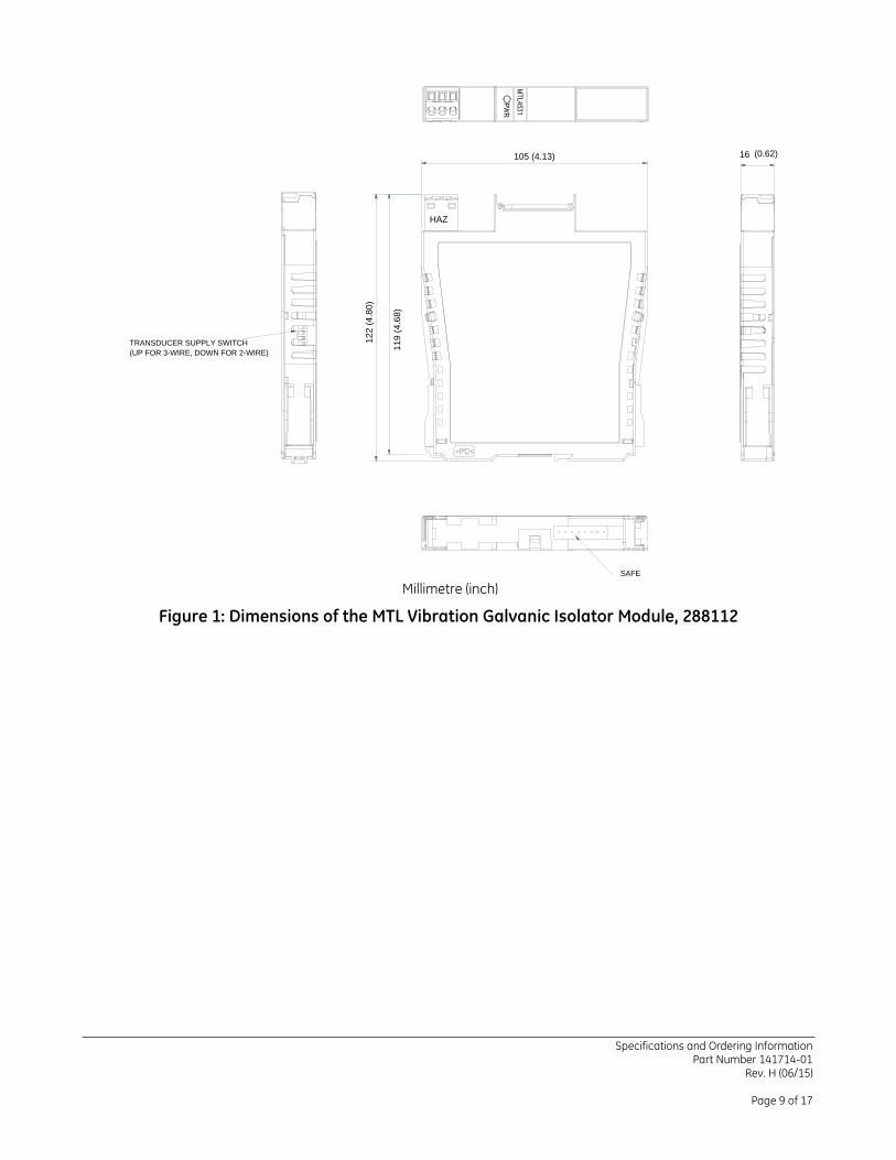
(UP FOR 3-WIRE, DOWN FOR 2-WIRE)
TRANSDUCER SUPPLY SWITCH
(0.62)16105 (4.13)
11
9 (
4.6
8)
12
2 (
4.8
0)
SAFE
HAZ
Millimetre (inch)
Figure 1: Dimensions of the MTL Vibration Galvanic Isolator Module, 288112
Specifications and Ordering Information Part Number 141714-01
Rev. H (06/15)
Page 10 of 17
S/N:141660
105 (
4.1
3)
122 (4.80)
HA
Z
7 (0.28)92 (3.62)
11
14
J2
8
SCRN
J4
7
BINHINHB
6
1
RETBSHLD
13
25
V2D4
D2
FS2
SKT2
13
14
8
7
13
14
8
7
13
14
8
7
13
14
8
7
!
DATE
CODE
LABEL
ERK08
2A-m
V1
0V
V2
0V
R2
R4
D6
SCRNA
INHINHA
1
J3RETA
4
SHLD
1 2 314
11
11 (0.43)CON9J1
33 (1.30)
13
14
8
7
13
14
8
7
13
14
8
7
13
14
7
8
25
13
V1
D5
D3
R3FS1
D1
V1
V2
0V
2A-m
143 (
5.6
3)
113 (
4.4
5)
SKT1
0V
ERK08
R1
Measurement Technology Ltd, Luton, England
5
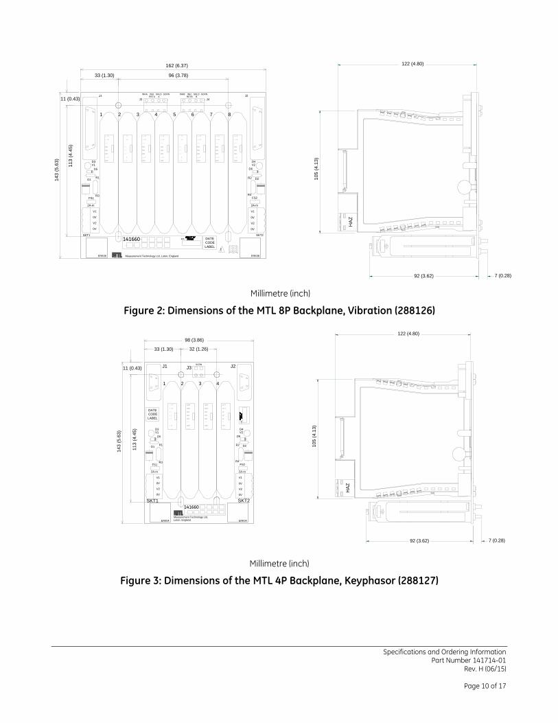
162 (6.37)
96 (3.78)
Millimetre (inch)
Figure 2: Dimensions of the MTL 8P Backplane, Vibration (288126)
S/N
:
141660
Measurement Technology Ltd, Luton, England
1 2 3 4
DATE
CODE
LABEL
ERK04ERK04
V1
0V
V2
0V
2A-m
V1
2A-m
V1
0V
V2
0V
V2
J1 J3
SKT1 SKT2
R2R1
FS1 FS2
D5 D6
D4D3
D2D1
R4R3
J2SCRN
113
(4.4
5)
33 (1.30)
143
(5.6
3)
11 (0.43)
32 (1.26)
98 (3.86)
5
11
9
6
7
8
13
14
6
11
5
9
7
8
13
14
7
8
13
14
7
8
13
14
10
5 (
4.1
3)
122 (4.80)
HA
Z
7 (0.28)92 (3.62)
Millimetre (inch)
Figure 3: Dimensions of the MTL 4P Backplane, Keyphasor (288127)
Specifications and Ordering Information Part Number 141714-01
Rev. H (06/15)
Page 11 of 17
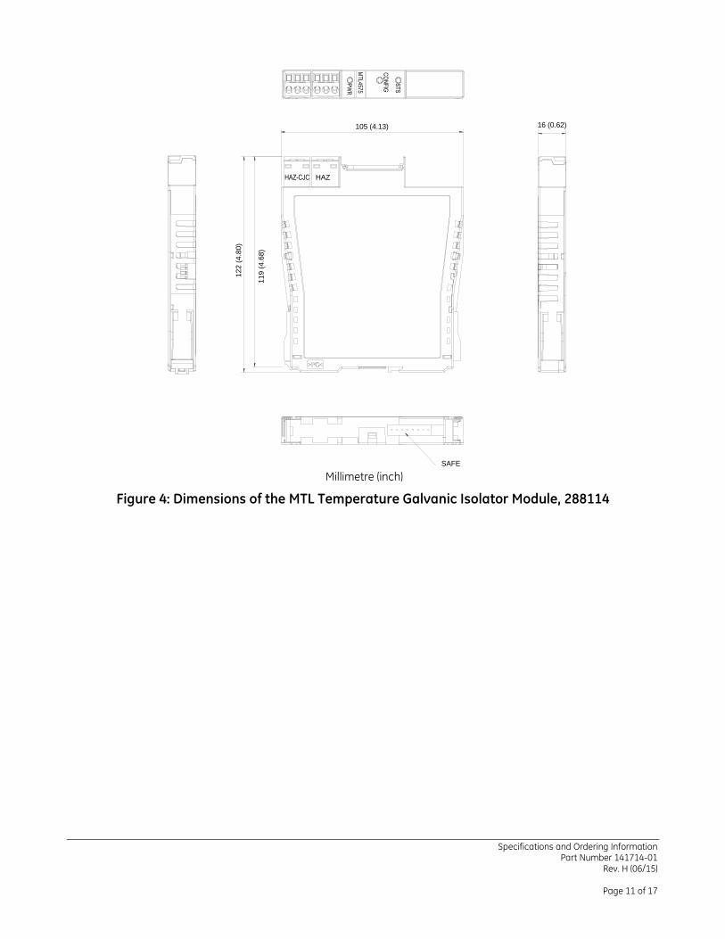
HAZ
16 (0.62)105 (4.13)
11
9 (
4.6
8)
12
2 (
4.8
0)
SAFE
Millimetre (inch)
Figure 4: Dimensions of the MTL Temperature Galvanic Isolator Module, 288114
Specifications and Ordering Information Part Number 141714-01
Rev. H (06/15)
Page 12 of 17
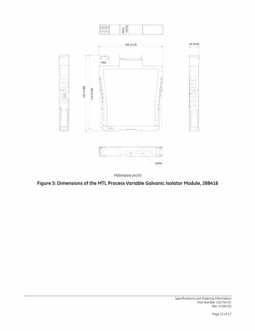
16 (0.62)105 (4.13)
11
9 (
4.6
8)
12
2 (
4.8
0)
SAFE
HAZ
Millimetre (inch)
Figure 5: Dimensions of the MTL Process Variable Galvanic Isolator Module, 288416
Specifications and Ordering Information Part Number 141714-01
Rev. H (06/15)
Page 13 of 17
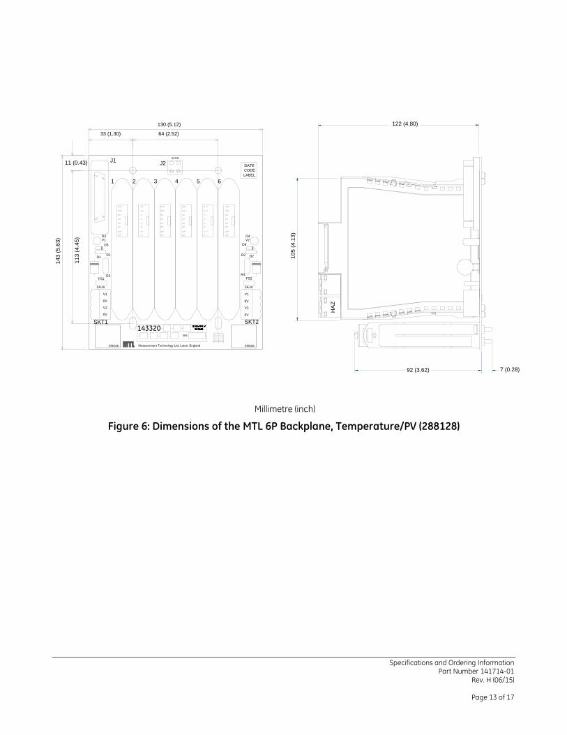
143320
130 (5.12)
CODE
DATE
14
13
6
LABEL
D4
D2
FS2
V2
2A-m
8
7
D6
R4
R2
14
13
5
14
13
14
13
SCRN
4
8
7
8
7
8
7
SKT2
0V
V2
0V
ERK06
V1
14
13
3
13
14
J1
1 2
8
77
8
R3
R1
14
11
11 (0.43)
13
D1
FS1
2A-m
14
3 (
5.6
3)
11
3 (
4.4
5)
25
D3
D5
V1
ERK06
SKT1
0V
V2
0V
V1
J2
Measurement Technology Ltd, Luton, England
64 (2.52)33 (1.30)
105
(4.1
3)
122 (4.80)
HA
Z
7 (0.28)92 (3.62)
Millimetre (inch)
Figure 6: Dimensions of the MTL 6P Backplane, Temperature/PV (288128)
Specifications and Ordering Information Part Number 141714-01
Rev. H (06/15)
Page 14 of 17
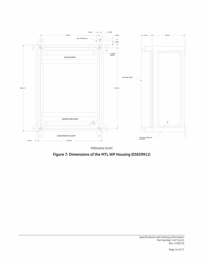
Millimetre (inch)
Figure 7: Dimensions of the MTL WP Housing (03639911)
Specifications and Ordering Information Part Number 141714-01
Rev. H (06/15)
Page 15 of 17
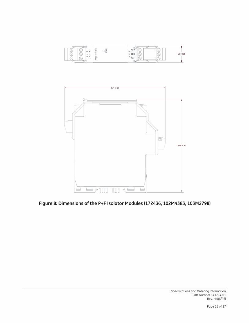
Figure 8: Dimensions of the P+F Isolator Modules (172436, 102M4383, 103M2798)
124 (4.9)
20 (0.8)
115 (4.5)
1
2
34
5
6
7
8
91
0
11
1
21
3
14
1
5
PW
R
KF
D2
-ST
C4
-Ex1
Specifications and Ordering Information Part Number 141714-01
Rev. H (06/15)
Page 16 of 17
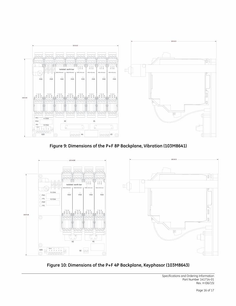
Figure 9: Dimensions of the P+F 8P Backplane, Vibration (103M8641)
Figure 10: Dimensions of the P+F 4P Backplane, Keyphasor (103M8643)
Specifications and Ordering Information Part Number 141714-01
Rev. H (06/15)
Page 17 of 17
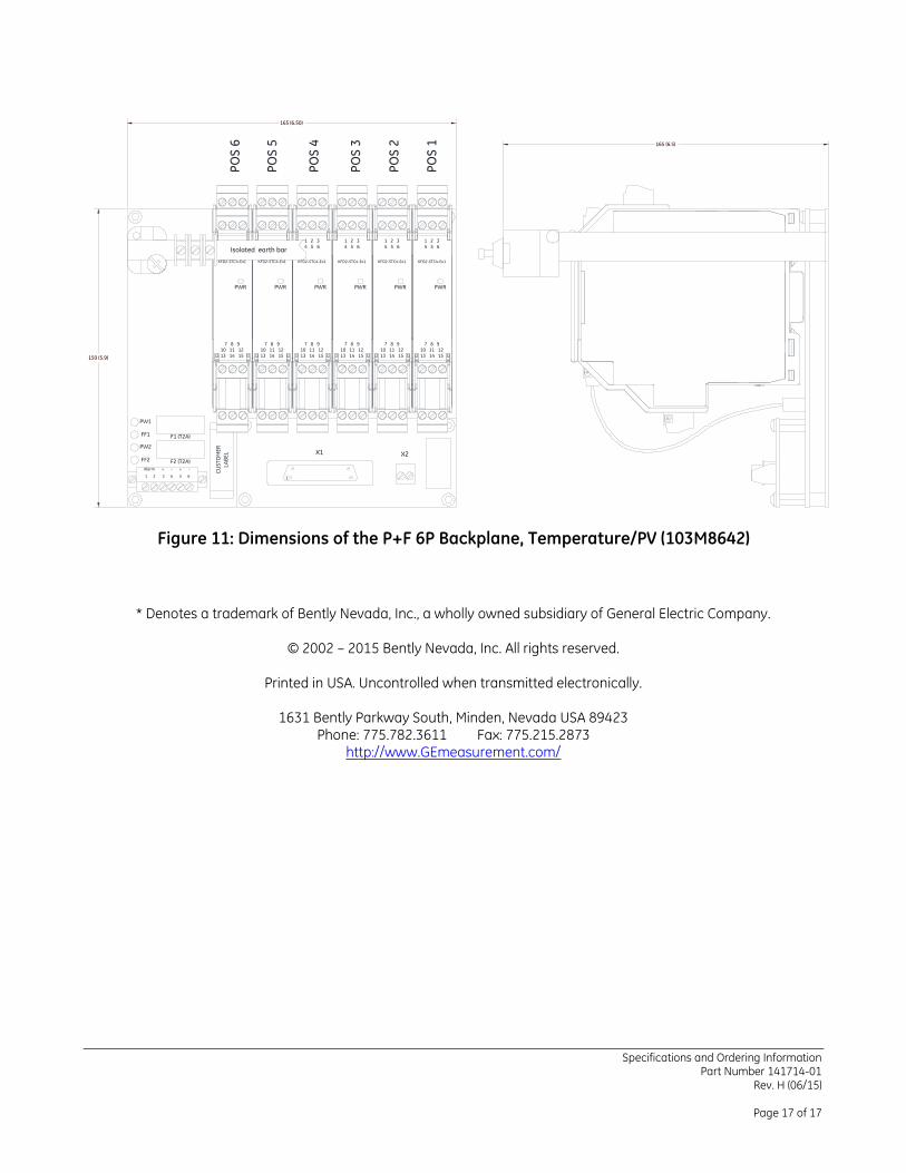
Figure 11: Dimensions of the P+F 6P Backplane, Temperature/PV (103M8642)
* Denotes a trademark of Bently Nevada, Inc., a wholly owned subsidiary of General Electric Company.
© 2002 – 2015 Bently Nevada, Inc. All rights reserved.
Printed in USA. Uncontrolled when transmitted electronically.
1631 Bently Parkway South, Minden, Nevada USA 89423 Phone: 775.782.3611 Fax: 775.215.2873
http://www.GEmeasurement.com/