3.3_cyber security r&d for microgrids_stamp_epri/snl microgrid
TRANSCRIPT

Sandia National Laboratories is a multi-program laboratory managed and operated by Sandia Corporation, a wholly owned subsidiary of Lockheed Martin Corporation, for the U.S. Department of Energy’s National Nuclear Security Administration under contract DE-AC04-94AL85000.
Cyber Security R&D for Microgrids
Panel Session: Emerging System Design Requirements – Security, Resiliency, and Reliability
Jason Stamp, Ph.D.
Sandia NaDonal Laboratories
1
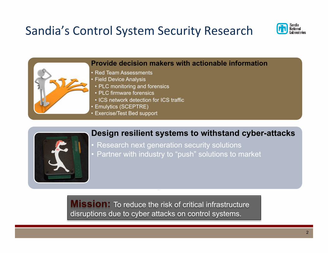
Sandia’s Control System Security Research
Mission: To reduce the risk of critical infrastructure disruptions due to cyber attacks on control systems.
Provide decision makers with actionable information • Red Team Assessments • Field Device Analysis
• PLC monitoring and forensics • PLC firmware forensics • ICS network detection for ICS traffic
• Emulytics (SCEPTRE) • Exercise/Test Bed support
Design resilient systems to withstand cyber-attacks • Research next generation security solutions • Partner with industry to “push” solutions to market
2
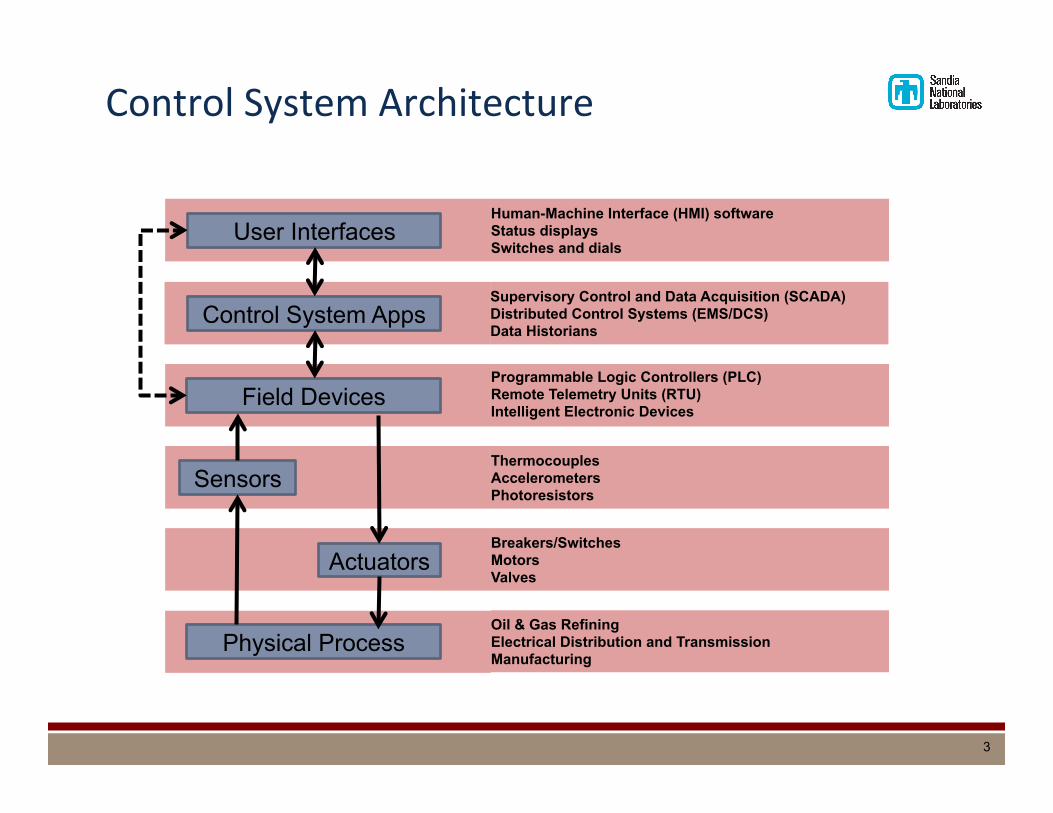
Control System Architecture
Human-Machine Interface (HMI) software Status displays Switches and dials
User Interfaces
Field Devices Programmable Logic Controllers (PLC) Remote Telemetry Units (RTU) Intelligent Electronic Devices
Sensors Thermocouples Accelerometers Photoresistors
Physical Process Oil & Gas Refining Electrical Distribution and Transmission Manufacturing
Actuators Breakers/Switches Motors Valves
Supervisory Control and Data Acquisition (SCADA) Distributed Control Systems (EMS/DCS) Data Historians
Control System Apps
3

RepresentaDve ICS TesDng Environments
Emuly&cs™/SCEPTRE
4

SCEPTRE OperaDonal Overview
§ SCEPTRE provides a cyber-‐physical environment to show interacDon between cyber-‐iniDated events and the physical world
§ Balances need for M&S accuracy against tesDng resources § Live system tesDng: potenDal damage to the real system and dangers to human life § Test bed systems: Expensive to build, maintain, configure, and operate § Labscale hardware tesDng setups: May require the context of a larger, networked
system
§ Devices (simulated, emulated, real) communicate/interact via ICS protocols § All ICS devices are able to interact with the process simulaDon, providing both
updates and subscribing to the current state of the simulaDon § Overall simulaDon is able to bridge mulDple infrastructures into the same
experiment to show interdependencies § Use cases:
§ Test and evaluaDon § Mission rehearsal § Other analysis: understand vulnerabiliDes and exploitable avenues, idenDfy criDcal
components on the control network, model infrastructure interdependencies, etc.
5
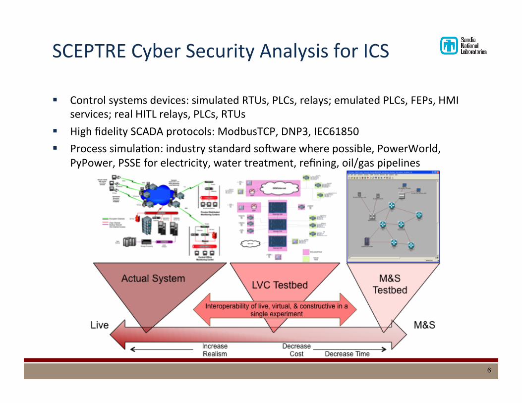
SCEPTRE Cyber Security Analysis for ICS
§ Control systems devices: simulated RTUs, PLCs, relays; emulated PLCs, FEPs, HMI services; real HITL relays, PLCs, RTUs
§ High fidelity SCADA protocols: ModbusTCP, DNP3, IEC61850 § Process simulaDon: industry standard so_ware where possible, PowerWorld,
PyPower, PSSE for electricity, water treatment, refining, oil/gas pipelines
6

Cyber Security Architecture
§ Microgrid cyber security reference architecture
§ In addiDon to DoD IA controls, addiDonal rigor will be applied to protecDng data-‐in-‐moDon and data-‐at-‐rest, along with ensuring such addiDonal rigor does not impede the operaDonal data exchange requirements of the SPIDERS microgrid
§ Defense-‐in-‐depth using: § Enclaves § FuncDonal Domains
7
4
V. DESIGN APPROACH AND DEFENSE-IN-DEPTH
Best practices for securing ICSs leverage network segmen-tation; for example, see [3], [6], and [7]. In most cases,however, network segmentation is focused on separation ofthe control system network from other less-trusted networks,such as the enterprise network and the Internet. The concept ofnetwork segmentation within the control system network itselfis addressed to a minimal degree in a recommended practicesdocument [3] published by the DHS Control System SecurityProgram (CSSP), but the additional complexities of configur-ing and managing such a network often result in this level ofdefense-in-depth being dismissed. In geographically dispersedcontrol systems and field devices, physical segmentation ofteninherently exists within ICS command and control networksdue to the employment of third-party providers for communi-cation services. This segmentation is not leveraged to enhancesecurity, however, as neither physical nor logical segmentationis currently used as a basis for providing additional defense-in-depth within modern ICS networks.
The SNL approach to designing a secure microgrid controlsystem network leverages segmentation to reinforce defense-in-depth practices. The microgrid control system network issegmented into enclaves defined by system functions, physicallocations, and security concerns. Enclaves are then grouped to-gether into functional domains that allow actors to collaboratein operational system functions that crosscut enclaves. Dataexchange worksheets describe communication between actorswithin enclaves and functional domains.
A. EnclavesAn enclave is a collection of computing environments that
is connected by one or more internal networks and is underthe control of a single authority and security policy [13]. Thisconcept of enclaves (already leveraged by DOD informationsystems in operation today [8], [13]) reduces the complexityof configuring and managing a segmented control systemnetwork. Enclaves support specific access and monitoringpolicies and enable more effective use of technological and ad-ministrative capabilities to enforce such policies. An enclave-based approach to segmentation is applicable to control systemnetworks as well, supporting access control and monitoring ofspecific control functions at a finer granularity.
Within the microgrid control system network, enclaves aredefined based on a suite of actors that participate in a particularsystem function, share geographical location, have similarsecurity concerns (e.g., IA controls), or share any combinationof these features. An enclave based on a particular systemfunction could include actors at multiple physical locations;for example, intelligent electronic devices (IEDs) that aregeographically dispersed may need to communicate their stateswith each other or an engineering console. In addition, actorsat a particular physical location may be segregated into sepa-rate enclaves based on whether they contribute to operations-related functions or cyber security-related functions.
This network segmentation process is demonstrated in Fig-ure 2 where enclaves (segmented by system function andphysical location) participate in functional domains defined
only by system function, rather than by physical location. Forexample, consider that all of the actors at Site II are groupedinto a single enclave (Enclave 3) based on physical location,whereas the actors at Site I are segregated into two enclaves(Enclave 1 and Enclave 2), which may be based on physicallocation, system function, security concerns, or a combinationof features.
Fig. 2. Example segmentation of network into enclaves and functionaldomains.
B. Functional DomainsAlthough some enclaves are defined based on actors that
participate in a particular system function, some actors neces-sarily crosscut enclaves that are defined by physical location,functional characteristics, or security concerns. For example,the EMS could interact with external actors at the electricalpoints of common coupling (PCCs), which could belong toenclaves defined by physical locations. Additionally, some ac-tors participate in multiple system functions. With the granularsegmentation of the actors into enclaves, communication (ordata exchange) between actors in separate enclaves may benecessary to accomplish system-level functional operations. Acollection of interacting enclaves is considered a functionaldomain.
This approach of using a domain to control interactionsbetween enclaves is similar to an approach championed byJames Rome at Oak Ridge National Laboratory (ORNL) [14].The ORNL approach uses enclaves to protect and segregatecomputing environments based on the type of informationand computing requirements of the resources located in theenclave. The need to communicate among enclaves drivesthe need to create a higher-level arbitration mechanism. Tosatisfy this need, collaborative domains are used to set accesspolicies and allow communication across enclave boundaries.The ORNL approach uses collaborative domains to handleenclave communication across geographically separated loca-tions with differing security policies. Our functional domainapproach builds on the collaborative domain mechanism, andeach functional domain contains a group of enclaves thataccomplish a system function.
Functional domains highlight areas of common communi-cation that define system operations. For instance, in Figure 2,Enclave 3, which is defined by physical location, participates

Cyber Security Data Exchange
§ Process: § Designate actors § Describe data flows using tables § Assign enclaves § Develop funcDonal domains § Design cyber security controls
8
TABLE IVDATA EXCHANGE ATTRIBUTES AND EXAMPLE VALUES.
Attribute Description Example Values
Exch
ange
Type Type of data exchange to occur monitor, control, report, writeInterval How often data exchange occurs e.g. milliseconds, secondsMethod How data will be exchanged unicast, multicast, broadcastPriority Relative importance of exchanging the data high, medium, lowLatency Tolerance Tolerance to delayed control or delayed data exchange high (delays do not affect operation), medium, low
Dat
a
Type Type of data to be exchanged voltage, setpoint, statusAccuracy Necessary precision/timeliness of data significant digits, time unitsVolume Amount of data to transferred per exchange e.g. bytes, kilobytes, etc.Reliability Necessity of access to control processes and data critical, important, informative
Info
rmat
ion
Ass
uran
ce Confidentiality Importance of preserving restrictions to controlprocesses and information access (based on risk tosystem operations and/or system security)
high, medium, low
Integrity Importance of preventing unauthorized changes tocontrol processes or data, including authenticity (basedon reliability with respect to operations)
high, medium, low
Availability Importance of timely and reliable access to controlprocesses and data (based on priority and latencytolerance with respect to operations)
high, medium, low
influence of actors to a particular enclave, the consequences ofboth local failures and vulnerabilities are isolated within thatenclave.
VIII. FIRST EXAMPLE FOR THE REFERENCEARCHITECTURE
The approach to segmenting the microgrid control systemnetwork is to first identify system functions with a granularitythat captures a complete system function but does not directlyoverlap another function. For example, a system functionmight be one listed in Section VI-B or could be more granular(such as sensing loss of utility power, isolating from the utility,disconnecting renewables, or energizing the microgrid). Oncethe functions are defined, a subset of actors contributing toeach function is listed. Actors that participate in a commonset of system functions can then be grouped together intoappropriate enclaves. If it makes sense, further enclave seg-mentation may be performed along physical boundaries or bydata exchange requirements. Lastly, in order to complete afull system function, two or more enclaves may need to com-municate; these enclaves are grouped into functional domainsand data exchange attributes are used to define communicationacross enclave boundaries.
A. System ConfigurationFigure 1 depicts a basic microgrid control system network
complete with a diesel generator, breakers, transformer, auto-matic transfer switch (ATS), IEDs, EMS, front-end processor(FEP), RE source, and HMI client/server. Some or all ofthose may be included as actors in the system functions.The network configuration is a typical flat network whereall actors communicate using Distributed Network Protocol(DNP3) over the same segment of a TCP!/IP! control network.The goal of applying the microgrid cyber security referencearchitecture to this example network is to arrive at a moresecure network configuration.
B. System FunctionsConsider a basic microgrid function: Connect/Disconnect
Microgrid as applied to this system. Islanding of the microgridwhen the installation’s distribution system loses power and isone of the key functions of the system’s operation. The poweractors typically involved in this system function include:
• IEDs at the utility (PCC) used to monitor voltage/currentsensors and to control breakers and disconnect switches,
• FEPs that handle communications for those IEDs, and• The EMS that optimizes and controls the microgrid.
The IEDs located at the PCCs are critical to the con-nect/disconnect function, but the EMS, in its oversight andoptimization role, will participate in many system functions.For the reconnection function, if the planned microgrid op-erations include permissive utility restoration by the operator,then the HMI client will be involved.
C. High-Level Data ExchangesTwo examples are considered, which resulted in the com-
pleted data exchange worksheets shown in Table V andTable VI. First, a typical IED collects data from a connectedpower component and processes the raw data. Often, data issent to the EMS via a FEP. The IED also receives controlmessages from the FEP over the network. These controlmessages may be in the form of an information request towhich the IED replies with an appropriate response or it maybe a control action the EMS wants the IED to execute on apower system device.
Second is a high-level overview of the data exchanges inwhich an EMS on the microgrid control system network isinvolved. The EMS receives power data from FEPs over theTCP/IP network, and it forwards that data to an HMI server.The power data is also processed by a local program that isused to automate control over the power network and mayresult in control signals being sent to appropriate IEDs. The
9
EMS may also receive manual control messages from anoperator of an HMI system. These control messages are sentfrom the HMI server via the EMS to the appropriate IEDs viaa FEP.
TABLE VEXAMPLE FOR DATA EXCHANGE (AGMC OPERATIONS)
FROM A FEP TO A GENERATOR IED
Data Exchange Attributes forAutomated Grid Management and Control (AGMC) Operations
Source FEP FEPDestination Generator controller Generator controller
ExchangeType monitor controlInterval seconds seconds or minutesMethod unicast unicastPriority medium mediumLatencyTolerance
medium low
DataType run/stop/ATS status, fuel
level, active & reactiveoutput, frequency
start/stop/mode/breakercontrol, voltage settings,governor droop settings
Accuracy 1 decimal, second 1 decimal, secondVolume bytes bytesReliability important critical
Information AssuranceConfidentiality medium mediumIntegrity medium highAvailability high high
TABLE VIEXAMPLE FOR DATA EXCHANGE (AGMC OPERATIONS)
BETWEEN AN EMS AND A HMI SERVER
Data Exchange Attributes forAutomated Grid Management and Control (AGMC) Operations
Source EMS HMI ServerDestination HMI Server EMS
ExchangeType report controlInterval seconds seconds to hoursMethod unicast unicastPriority medium mediumLatencyTolerance
medium medium
DataType HMI-monitored subset of
data listed for exchangesthat include the EMS
HMI-relevant subset ofsystem control points datalisted for EMS exchanges
Accuracy 1 decimal, seconds 1 decimal, secondsVolume kilobytes bytesReliability important important
Information AssuranceConfidentiality medium mediumIntegrity high highAvailability medium medium
D. Network SegmentationAs shown in Figure 3, five different enclaves were created
for this example of a generic electric power system andmicrogrid control system network. The Operator enclavethat segments the operator’s HMI client from the rest of the
network was created because of potentially unique securityconcerns. Actors within this enclave may be at higher risk,because a human operator has the potential to be an insideror carry in malicious software via removable media. TheServer enclave was created to contain server-based systemsthat automate parts of the microgrid control system networkand require minimal human interaction. The importance ofthe EMS to the overall functionality of the microgrid andthe broad influence it has over the devices, in addition to thesheer volume of data being exchanged, warrants the creationof its own enclave. The remaining enclaves were definedthrough consideration of the system functions that support themicrogrid operational modes and the data exchange attributesrelevant to each IED and their respective power components.The enclaves include:
• Distribution: detecting utility power status, maintainingsystem protection, and isolating/re-syncing the microgrid
• Renewables: disconnecting/reconnecting inverter-basedrenewables
• Generation: starting, syncing, power control, and unload-ing of microgrid generators
Fig. 3. Implementation of enclaves and functional domains to segment themicrogrid control system network.
Based on the microgrid system functions and data ex-changes necessary for their reliable operation, Figure 3 illus-trates the four functional domains created:
• Domain A: power data, meter data, breaker/switch po-sitions, alarms, and operator control signals are sentbetween the operator HMI client in the Operator enclaveand the HMI server/EMS in the Server enclave.
• Domain B: microgrid isolation controls, re-syncing com-mands, and breaker controls are sent between actors inthe Isolation enclave and the FEP in the Server enclave
• Domain C: disconnect and connect commands are sent
Data Exchange Table Format Data Exchange Example
Example Flat Control System
8
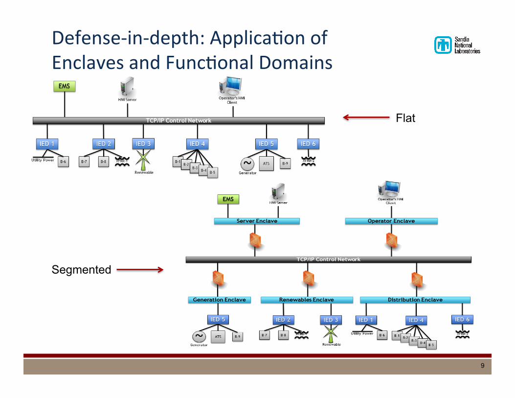
Defense-‐in-‐depth: ApplicaDon of Enclaves and FuncDonal Domains
9
Flat
Segmented
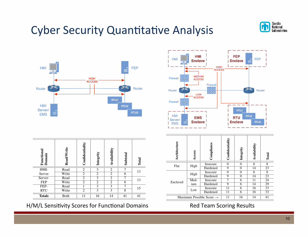
Cyber Security QuanDtaDve Analysis
10
11
Fig. 6. Reference architecture test network (enclaved configuration).
the the “Type” attribute of the “Exchange” section for the ap-plicable data exchange worksheets (Table IV). Here, “monitor”and “report” can be considered as “reading” (from the field tothe control center) and likewise all control traffic outward tothe field devices can be labeled “write.” Furthermore, “high,”“medium,” and “low” are mapped to the numerical values 1,2, and 3 respectively (although any could be used, the simplestapproach is simple incrementing values). Summarizing thedata exchange characteristics for each functional domain withthe read/write strategy yields the data shown in Table VII.
TABLE VIISUMMARIZED DATA ATTRIBUTES FOR EXAMPLE MICROGRID CONTROL
SYSTEM.
Func
tiona
lD
omai
n
Rea
d/W
rite
Con
fiden
tialit
y
Inte
grity
Avai
labi
lity
Subt
otal
Tota
l
HMI- Read 2 3 2 7 13Server Write 2 2 2 6Server- Read 2 3 2 7 13FEP Write 2 2 2 6FEP- Read 1 3 3 7 15RTU Write 2 3 3 8
Totals Both 11 16 14 41 41
The testing against this example system was performed bycyber security Red Teams, modeling relevant threats (SectionIII). The tests were scored by carefully monitoring the dataflows that form the functional domains during the exercise.If any flow in a functional domain was impacted accordingto confidentiality, integrity, or availability, then the affectedsecurity attribute was scored as a zero; otherwise, if unaffectedit was scored according to the value in Table VII. Obviously,if any security attribute was impacted, then test score was lessthan perfect (100% of raw value 41). During testing, both readand write flows were impacted, sometimes in different ways.
B. Quantitative Red Team Test ResultsFor the purpose of testing, three government cyber Red
Teams were engaged, including the one from SNL. Differentpermutations of the test system were employed to gauge theeffectiveness of the cyber security measures. They included:
• Architecture: whether the enclaving/functional domainstrategy is being used, or if the control system networkis flat
• Access: where in the network the modeled adversary hasaccess (three choices, shown in Figure 7)
• Compliance: a binary variable representing the cybersecurity of the platforms in the system, with “hardened”representing systems that are fully patched and securedaccording to current best practices, and “insecure” mean-ing they are not; due to the operational reliability neces-sary from energy control systems, hardware and softwarepatches are not always applied in a timely manner
(a) Flat network
(b) Enclaved network
Fig. 7. Red Team access locations for the quantitative testing.
C. Experiment ResultsPer the previous discussion, a total of eight versions of the
notional microgrid control system network were deployed andtested in a laboratory setting at SNL. The Red Teams were
12
constrained to reasonable threat parameters (specifically, the“Mid” range shown in Table I). The results are in Table VIII.
TABLE VIIIMICROGRID CYBER SECURITY TEST RESULTS.
Arc
hite
ctur
e
Acc
ess
Com
plia
nce
Con
fiden
tialit
y
Inte
grity
Avai
labi
lity
Tota
l
Flat High Insecure 0 0 8 8Hardened 9 0 14 23
Enclaved
High Insecure 0 0 8 8Hardened 9 0 14 23
Med- Insecure 7 6 11 24ium Hardened 9 6 14 29
Low Insecure 11 6 16 33Hardened 11 6 16 33
Maximum Possible Score ! 11 16 14 41
The results indicate that each progressive variation to thereference implementation led to an increase in system security.More interesting is the fact that adding hardened systems tothe enclaved versions of the reference implementation onlyincreased the security by a small amount, and the smallincrease provided was only useful when the threat had mediumor high access to the system under test. The limited testresults suggest that defense-in-depth provided by networksegmentation is more effective at limiting the damage fromcyber attack than platform security (which is still important,but this is a key result given the difficulties involved in keepingcontrol systems up-to-date against vulnerabilities). Also, givenan enclaved security architecture, access should be minimizedfor potential attackers (which suggests any number of knownand feasible additional security controls, including those thatguard against insiders or insider-equivalent access).
X. CONCLUSIONS AND ADDITIONAL WORK
This document summarizes the on-going cyber securitywork and resulting cyber security reference architecture fora secure microgrid control system network. The architecturepresented here provides guidelines and security recommen-dations for the implementation of a secure microgrid controlsystems. The design approach supports the management ofa secure control system for the microgrid using functionalsegmentation to provide defense-in-depth at the control systemlevel. Furthermore, the systematic approach used to define andrank data flows in the development of enclaves and functionaldomains can re-used to support a quantitative scoring systemfor Red Team analysis, which is itself a significant result.Future versions can include a stronger focus on the designprinciples of monitoring and reconfiguration, in addition to anassessment of IA controls and how they can be met using thereference architecture and industry best practices for securingcontrol systems.
ACKNOWLEDGEMENTS
The authors would like to thank the DOE Office of Elec-tricity Delivery and Energy Reliability for their support ofthis work, as well as our colleagues from SNL, ORNL,Idaho National Laboratory (INL), Massachusetts Institute ofTechnology Lincoln Laboratory (MIT-LL), US Pacific Com-mand (USPACOM), and the Joint Information OperationsWarfare Center (JIOWC) for their reviews, suggestions, andparticipation in the work.
REFERENCES
[1] Systems and Network Analysis Center (SNAC), A Framework forAssessing and Improving the Security Posture of Industrial ControlSystems (Version 1.1), technical report, National Security Agency(NSA), August 2010.
[2] Brian Van Leeuwen, Impacts of IPv6 on Infrastructure Control Systems,Sandia Report SAND2007-0383P, Sandia National Laboratories (SNL),Albuquerque, NM, September 2007.
[3] Control System Security Program (CSSP), Recommended Practice:Improving Industrial Control Systems Cybersecurity with Defense-In-Depth Strategies, technical report, National Cyber Security Division(NCSD), Department of Homeland Security (DHS), October 2009.
[4] CSSP, Catalog of Control Systems Security: Recommendations forStandards Developers, technical report, NCSD, DHS, September 2009.
[5] CSSP, Common Cybersecurity Vulnerabilities in Industrial ControlSystems, technical report, NCSD, DHS, May 2011.
[6] Smart Grid Interoperability Panel (SGIP)–Cyber Security WorkingGroup (CSWG), Guidelines for Smart Grid Cyber Security, NISTInteragency Report (NISTIR) 7628, Vol. 1–3, National Institute ofStandards and Technology (NIST), August 2010.
[7] Keith Stouffer, Joe Falco, and Karen Scarfone, Guide to IndustrialControl Systems (ICS) Security, NIST Special Publication (SP) 800-82,NIST, Gaithersburg, MD, June 2011.
[8] Department of Defense (DOD), DOD Information Assurance Certifi-cation and Accreditation Process (DIACAP), DOD Instruction (DODI)8510.01, DOD, November 2007.
[9] SNAC, Defense in Depth: A Practical Strategy for Achieving Infor-mation Assurance in Today’s Highly Networked Environments, tech-nical report, NSA, March 2010, http://www.nsa.gov/ia/ files/support/defenseindepth.pdf.
[10] Supply Chain Management Center, The ICT SCRM Community Frame-work Development Project: Final Report, technical report, Universityof Maryland, College Park, MD, December 2011.
[11] Architecture and Design Considerations for Secure Software, SoftwareAssurance Pocket Guide Series: Development (Volume V), February2011.
[12] David P. Duggan, Sherry R. Thomas, Cynthia K. Veitch, and LauraWoodard, Categorizing Threat: Building and Using a Generic ThreatMatrix, Sandia Report SAND2007-5791, SNL, Albuquerque, NM,September 2007.
[13] DOD, Information Assurance (IA) Implementation, DODI 8500.2, DOD,February 2003.
[14] James A. Rome, Enclaves and Collaborative Domains, technical report,Oak Ridge National Laboratory (ORNL), Oak Ridge, TN, 2003, http://www.ornl.gov/⇠webworks/cppr/y2001/pres/117259.pdf.
[15] Institute of Electrical and Electronics Engineers (IEEE) Standards Coor-dinating Committee 21 on Fuel Cells, Photovoltaics, Dispersed Gener-ation, and Energy Storage, IEEE Guide for Smart Grid Interoperabilityof Energy Technology and Information Technology Operation with theElectric Power System (EPS), End-Use Applications, and Loads, IEEEStd 2030TM-2011, IEEE, New York, NY, September 2011.
ACRONYMS
ACL access control listAGMC automated grid management and controlATS automatic transfer switchBITW bump-in-the-wireCSCM cyber security configuration managementCSSA cyber security situational awareness
H/M/L SensiDvity Scores for FuncDonal Domains Red Team Scoring Results
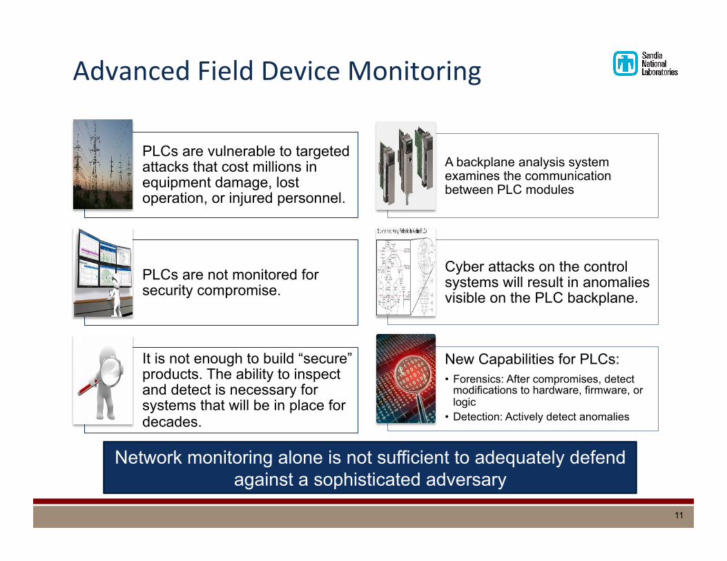
Advanced Field Device Monitoring
Network monitoring alone is not sufficient to adequately defend against a sophisticated adversary
PLCs are vulnerable to targeted attacks that cost millions in equipment damage, lost operation, or injured personnel.
PLCs are not monitored for security compromise.
It is not enough to build “secure” products. The ability to inspect and detect is necessary for systems that will be in place for decades.
A backplane analysis system examines the communication between PLC modules
Cyber attacks on the control systems will result in anomalies visible on the PLC backplane.
New Capabilities for PLCs: • Forensics: After compromises, detect
modifications to hardware, firmware, or logic
• Detection: Actively detect anomalies
11

Advanced Field Device Monitoring
§ WeaselBoard plugs into the backplane and listens to the conversaDons between control system modules
§ There is a lot of granularity in these conversaDons, which allows WeaselBoard to uniquely observe behavior of the control system independent of the processor and alert when the system is not operaDng within a specifically defined manner
§ Because it alerts on effects of an adack in progress, and not on signatures of prior adacks, WeaselBoard can detect zero-‐day exploits
Processor Module
Runs Process Logic
PLC Backplane
Comms Module
Connects the PLC to the Network
I/O Module
Connects the PLC to the Process
Isolation
WeaselBoard
Detects Intruders
12
Other ICS Cyber Security RecommendaDons
§ InvesDgate all miDgaDon opDons, covering defend, detect, react, and recover (including incident management/recovery plans)
§ Develop and install detecDon capabiliDes for adack/anomaly indicators § Complementary opDons include network traffic monitoring and advanced hardware
monitoring § Reduce troubleshooDng duraDon
§ Develop effecDve environments/procedures for tesDng § Minimize adacker opportuniDes for device configuraDon or firmware access
(possibly disallowing such network traffic) § Develop logic-‐ and tamper-‐checking tools for devices and systems § Focus on cyber security assessment for field devices
13

Sandia National Laboratories is a multi-program laboratory managed and operated by Sandia Corporation, a wholly owned subsidiary of Lockheed Martin Corporation, for the U.S. Department of Energy’s National Nuclear Security Administration under contract DE-AC04-94AL85000.
Cyber Security R&D for Microgrids
Panel Session: Emerging System Design Requirements – Security, Resiliency, and Reliability
Jason Stamp, Ph.D.
Sandia NaDonal Laboratories
14