33 10 00 water piping, structures & appurtenances(rev ... 10 00 water pipi… · which may have...
TRANSCRIPT
American States Utility Services 33 10 00 - 1 Water Pipe, Structures & Appurtenances Revision Date: 03/31/2016
33 10 00 WATER PIPE, STRUCTURES & APPURTENANCES
SECTION 1 - GENERAL
1.1 SUMMARY
A. This Section includes requirements for water systems and water-distribution pipeline, water structures, and appurtenances outside the building for water and fire mains
B. All materials to be installed shall be purchased in accordance with all applicable provisions of the Buy American Act.
C. Utility furnished products include water meters that shall be delivered to the site and installed by the contractor.
D. The intent and purpose of these specifications is to require a complete and satisfactory installation in every respect and any defects in material or workmanship shall be cause for the replacement and correction of such defect as directed by the Utility.
1.2 QUALITY ASSURANCE
A. Prior to shipment each joint of pipe shall be stamped by an independent testing laboratory, certifying compliance with the specifications. Pipe sizes indicated shall be nominal inside diameter of the pipe.
B. Regulatory Requirements:
1. The Contractor shall comply with Utility requirements.
2. Plastic piping shall comply with NSF 14 for plastic potable-water-service piping. Include marking "NSF-pw" on piping.
3. Fire service main products shall comply with FMG's "Approval Guide" or UL's "Fire Protection Equipment Directory".
4. Fire service main piping for fire suppression shall comply with NFPA 24 for materials, installations, tests, flushing, and valve and hydrant supervision.
5. Procedures and personnel for Steel Support Welding shall be qualified in accordance with AWS D1.1/D1.1M, "Structural Welding Code - Steel."
6. Steel Piping Welding
a. Processes and operators shall be qualified in accordance ASME Boiler and Pressure Vessel Code: Section IX, "Welding and Brazing Qualifications."
b. The Contractor shall comply with provisions in ASME B31 Series, "Code for Pressure Piping."

American States Utility Services 33 10 00 - 2 Water Pipe, Structures & Appurtenances Revision Date: 03/31/2016
c. Each welder shall be certified to have passed AWS qualification tests for welding processes involved and that certification is current.
7. All marking shall be in compliance with ASME A13.1 for lettering size, length of color field, colors, and viewing angles of identification devices.
8. All materials for water-service piping and specialties for domestic water shall comply with NSF 61.
C. HDPE Piping
1. HDPE pipe shall be furnished by manufacturers who are fully experienced, reputable, and qualified in the manufacture of the HDPE pipe to be furnished.
2. All HDPE pipe and fittings shall be from a single manufacturer.
3. Inspection of the pipe may be made by any representative of the Utility after delivery. Pipe rejected after delivery shall be identified as such, and shall be immediately removed from the job site.
4. The physical appearance of the HDPE pipe having deformities such as concentrated ridges, discoloration, excessive spot roughness, pitting, varying wall thickness, etc., shall constitute sufficient basis for rejection.
5. HDPE pipe shall be homogenous throughout and shall be free of visible cracks, holes, foreign inclusions or other defects.
6. HDPE pipe with gashes, nicks, abrasions or any such physical damage which may have occurred during storage and/or handling which are wider or deeper than 10 percent of the wall thickness, shall not be used and shall be removed from the job site.
7. Contractor performing installation of fused HDPE shall have successfully completed installation of 3000 linear feet of fused HDPE prior to date of installation on the project.
D. Fusible PVC Piping
1. Fusible polyvinylchloride pipe shall be tested at the extrusion facility for properties required to meet all applicable parameters as outlined in either AWWA C900, AWWA C905, applicable sections of ASTM D2241, ASTM D3034, or ASTM F679 .
2. Testing priority for Fusible PVC Pipe shall be in conformance with AWWA C900 and AWWA C905, except for pipe made to the ASTM D3034 or ASTM F679 standards, which shall be tested to those standards.
3. Contractor performing installation of Fusible PVC shall have successfully completed installation of 3000 linear feet of Fusible PVC prior to date of installation on the project.
American States Utility Services 33 10 00 - 3 Water Pipe, Structures & Appurtenances Revision Date: 03/31/2016
4. Fusion Technician shall be fully qualified by the pipe supplier to install fusible polyvinylchloride pipe of the type(s) and size(s) being used. Qualification shall be current as of the actual date of fusion performance on the project. The Fusion Technician shall have successfully fused at least 3000 lf of Fusible PVC prior to date of installation on the project
5. Warranty
a. The pipe and the fusion services shall be warranted for 2 years per the Utility’s standard warranty.
E. All piping and other appurtenances provided as part of the project shall be comprised of non-asbestos containing material.
1.3 SUBMITTALS
A. The contractor shall submit the following prior to construction and use:
1. Product Data: For each type of product indicated to be installed on the project.
2. Shop Drawings:
a. Detail of all pipe types, sizes, and fittings to be used on the project.
b. Detail of Equipment, to be used on the project to include but shall not be limited to valves, meters, back-flow prevention devices, enclosures, fire hydrants, etc.
c. Detail precast concrete vault assemblies and indicate dimensions, method of field assembly, and components.
3. Field quality-control test reports.
4. Operation and maintenance data.
5. Dielectric fittings.
6. Identification devices.
7. Welding Certificates
8. Post construction testing results
9. Concrete Mix Design
B. Fusible PVC Submittals
1. The following Product Data is required from the Fusible PVC pipe supplier and/or fusion provider:

American States Utility Services 33 10 00 - 4 Water Pipe, Structures & Appurtenances Revision Date: 03/31/2016
a. Pipe Size
b. Pressure Class per applicable standard
c. Color
d. Recommended Minimum Bending Radius
e. Recommended Maximum Safe Pull Force
f. Pipe and fusion services warranty information.
g. Written procedural documentation for piping products including proper handling and storage, installation, tapping, and testing.
h. Fusion technician qualification indicating conformance with this specification.
2. Certification by pipe manufacturer that the personnel performing fusing of polyvinylchloride pipe and fittings have training to install fusible polyvinylchloride pipe of the type(s) and size(s) being used.
3. Post-Construction Submittals shall include a fusion report for each fusion joint performed on the project, including joints that were rejected. Specific requirements of the Fusion Technician’s joint report shall include:
a. Pipe Size and Thickness
b. Machine Size
c. Fusion Technician Identification
d. Job Identification
e. Fusion Joint Number
f. Fusion, Heating, and Drag Pressure Settings
g. Heat Plate Temperature
h. Time Stamp
i. Heating and Cool Down Time of Fusion
j. Ambient Temperature
4. HDPE Pipe
a. Certification by manufacturer of fusing equipment that the personnel performing fusing of HDPE pipe and fittings have successfully completed training in handling replacement pipe materials, butt fusion of pipe joints, saddle fusion of fittings for
American States Utility Services 33 10 00 - 5 Water Pipe, Structures & Appurtenances Revision Date: 03/31/2016
service laterals, and operation and maintenance of all equipment to be used.
1.4 REFERENCES
ANSI B16.1 Cast Iron Pipe Flanges and Flanged Fittings
ANSI B16.5 Pipe Flanges and Flanged Fittings
AWWA C110 Ductile-Iron and Gray-Iron Fittings, 3 Inches through 48 Inches, for Water and Other Liquids
ASTM A126 Standard Specification for Gray Iron Castings for Valves, Flanges, and Pipe Fittings
ASTM A536 Ductile Iron Castings
ASTM C891 Practice for installation of Underground Precast Concrete Utility Structures
ASTM D1248 Polyethylene Plastics Molding and Extrusion Materials
ASTM D1784 Rigid Poly (Vinyl Chloride) (PVC) Compounds and Chlorinated Poly(Vinyl Chloride) (CPVC) Compounds
ASTM D1785 Poly (Vinyl Chloride) (PVC) Plastic Pipe, Schedules 40, 80, and 120
ASTM D2152 Test Method for Degree of Fusion of Extruded Poly(Vinyl Chloride) (PVC) Pipe and Molded Fittings by Acetone Immersion
ASTM D2665 Poly (Vinyl Chloride) (PVC) Plastic Drain, Waste, and Vent Pipe and Fittings
ASTM F477 Elastomeric Seals (Gaskets) for Joining Plastic Pipe
ASTM F1057 Standard Practice for Estimating the Quality of Extruded Poly (Vinyl Chloride) (PVC) Pipe by the Heat Reversion Technique
AWWA C105 Polyethylene Encasement for Ductile-Iron Piping for Water and Other Liquids
AWWA C110 Ductile-Iron and Gray-Iron Fittings, 3 Inches through 48 Inches, for Water and Other Liquids
AWWA C111 Rubber-Gasket Joints for Ductile-Iron and Gray-Iron Pressure Pipe and Fittings
AWWA C115 Flanged Ductile-Iron and Gray-Iron Pipe with Threaded Flanges
AWWA C151 Ductile-Iron Pipe, Centrifugally Cast in Metal Molds or Sand-Lined

American States Utility Services 33 10 00 - 6 Water Pipe, Structures & Appurtenances Revision Date: 03/31/2016
Molds, for Water or Other Liquids
AWWA C153 AWWA Standard for Ductile Iron Compact Fittings for Water Service
AWWA C500 Gate Valves for Water and Sewerage Systems
AWWA C502-85 Dry-Barrel Fire Hydrants
AWWA C509 Reduced Wall, Resilient-Seated Gate Valves for Water Supply Service
AWWA C515 Resilient-Seated Gate Valves for Water Supply Service
AWWA C600 Installation of Ductile-Iron Water Mains and their Appurtenances
ASTM A126 Gray Iron Castings for Valves, Flanges, and Pipe Fittings
AWWA C605 Standard for Underground Installation of Polyvinyl Chloride (PVC) Pressure Pipe and Fittings for Water
AWWA C900 Polyvinyl Chloride (PVC) Pressure Pipe, 4 Inches though 12 Inches, for Water
AWWA C905 Standard for Polyvinyl Chloride (PVC Pressure Pipe and Fabricated Fittings, 14 in. through 48 in. (350mm-1200mm), for Water Distribution
AWWA M23 AWWA Manual of Supply Practices PVC Pipe—Design and Installation, Second Edition
FEDSPEC SS-S-00210 Sealing Compound, Preformed Plastic for Pipe Joints
NSF-14 Plastics Piping System Components and Related Materials
NSF-61 Drinking Water System Components--Health Effects
SPC Standard Plumbing Code of the SBCCI
PPI TR-2 PVC Range Composition Listing of Qualified Ingredients
UL 246-79 Hydrants for Fire Protection Service
UNI-PUB-08 Tapping Guide for PVC Pressure Pipe
UPC Uniform Plumbing Code
1.5 PROJECT CONDITIONS
A. The Contractor shall not interrupt water distribution service to facilities or others unless permitted under the following conditions and then only after arranging to provide temporary water distribution service according to requirements indicated.

American States Utility Services 33 10 00 - 7 Water Pipe, Structures & Appurtenances Revision Date: 03/31/2016
1. The Contractor shall notify Utility no fewer than two weeks in advance of proposed interruption of service.
2. The Contractor shall not proceed with interruption of water distribution service without Utility’ written permission.
3. Water service interruption shall be limited to four hours or less.
4. In Cases where service is interrupted for longer than four hours, the contractor shall provide bottled water and portable toilets to the facility being impacted in quantities determined by Utility at no additional cost to Utility.
B. Boring logs and a geotechnical report may be included in the contract documents. If included the boring logs indicate the soil and groundwater conditions at the boring location at the time of the boring. Conditions may change away from the actual boring location and may change with time. The boring logs and geotechnical report are made available to the Contractor for his information to be used at his own risk. The Contractor is responsible for any conclusions to be drawn from the boring logs including the character of the materials to be encountered and the degree of difficulty to be expected in the performance of the work. The Contractor is encouraged to perform his own subsurface investigation.
C. Horizontal Directional Drilling operations shall limit vibrations transmitted to surrounding structures so as not to cause damage. Any damage to any structures, roadways or any other items shall be repaired at the Contractor’s expense.
SECTION 2 – MATERIALS
2.1 GENERAL REQUIREMENTS
A. All pipe shall generally be PVC including restrained joint pipe unless otherwise noted on the plans or directed by the Utility.
B. Buried pipe shall be designed to withstand all internal pressures and external loads with a minimum depth to cover of 3 feet for pipelines 8 inches and smaller in diameter, a minimum cover of 3 ½ feet for pipeline 10 inches and larger in diameter, and greater depths of cover where required by the Plans, plus an H-20 live load in accordance with AASHTO specifications. In wet areas pipe shall be bedded in stone to spring line.
C. All fittings shall be of at least the same class as the pipe with which they are used. Ductile iron mechanical joint fittings shall be used with all ductile iron pipe, and PVC pipe 3-inches or larger in diameter.
D. All valves shall have standard mechanical joint ends, except where flanged or other type ends are specifically specified. Flanged valves, where required, shall be furnished with operating nuts, or handwheels as necessary. All valves shall be of at least the same class as the pipe with which they are used. A valve box shall be provided for each underground valve.

American States Utility Services 33 10 00 - 8 Water Pipe, Structures & Appurtenances Revision Date: 03/31/2016
E. Concrete pipe vaults, or precast manholes, with cast iron cover shall be provided for all air/vacuum valves.
F. Main line valves shall be installed at locations determined by the Utility and shown on plans. All valves larger than 12-inches or installed at a depth of 8-feet or greater shall be enclosed in a manhole. Valves shall be installed approximately at 500-foot intervals, and at all main line tees and crosses on both the main line and the branch line. Valves shall be installed at other locations shown in the Standard Details or on the plans.
G. Underground Fire Service Main Piping shall be ductile iron pipe.
2.2 POLYVINYL CHLORIDE (PVC) – BELL WITH GASKET AND SPIGOT END
A. All PVC piping shall be made from a PVC compound conforming to cell classification 12454 per ASTM D1784.
B. PVC Pipe shall comply with UL 1285 for fire-service mains if indicated.
C. Water main pipe 2-inches and smaller shall be manufactured as follows:
1. Grade 1 PVC compound material as defined in ASTM D-1784.
2. Pipe shall be Schedule 80 PVC.
3. Fittings shall be solvent weld Schedule 80 PVC.
4. The pipe shall be plainly marked with the manufacturer’s name, size, material (PVC) type and grade or compound, NSF seal, pressure rating and reference to appropriate product standards.
D. All PVC pipe (4-inch through 24-inch diameter) and couplings shall be manufactured as follows:
1. Manufactured using virgin compounds as defined in ASTM D-1784, with a 4000 psi HDB rating and designated as PVC 1120 to be in strict accordance with AWWA C-900.
2. Pipe shall be C-900 Class 200 and conform to the thickness requirements of DR18. Piping 14-inches to 24-inches shall be C-905 Class 200 and conform to the thickness requirements of DR 18.
3. Pipe shall be manufactured to withstand 755 psi quick burst pressure tested in accordance with ASTM D-1599 and withstand 500 psi for a minimum of 1,000 hours tested in accordance with ASTM D-1598.
4. Couplings shall be compression, twin gasket type in accordance with ASTM D-3139 for push-on joints and ASTM F-477 for elastomeric seals (gaskets).
5. PVC fittings are not acceptable for water mains 3-inches or greater.

American States Utility Services 33 10 00 - 9 Water Pipe, Structures & Appurtenances Revision Date: 03/31/2016
6. Threaded PVC connections shall not be permitted, nor shall cemented joints except as part of factory made fittings and adapters.
7. The pipe joints shall be of the integral bell type with rubber gaskets shall conform to the requirements of ASTM D-3139 or ASTM F-477.
8. Ductile iron fittings to PVC pipe shall be adequately supported on a firm trench foundation.
9. Fittings shall be for bell and spigot pipe or plain end pipe as applicable.
E. PVC Pipe Restraint for PVC C-900 shall be as follows when the restraint lengths as shown on the plans can be met:
1. The restraint shall be manufactured of ductile iron conforming to ASTM A536.
2. The restraint devices shall be coated with a minimum of two coats of liquid thermoset epoxy coating with heat cure to follow each coat. All casting bodies shall be surface pretreated with a phosphate wash, rinse, and sealer before drying. The coating shall be electrostatically applied and heat cured. The coating shall be a polyester based powder to provide corrosion, impact, and UV resistance. The coating system shall be MEGA-BOND, by EBAA Iron, Inc. or Utility approved equal.
3. The combination of the restraint(s) and fasteners shall have a pressure rating to the full pressure rating of the pipe. The restraint shall have a two to one safety factor.
4. Restraint for ductile iron fittings shall be a split serrated ring used to grip the plain-end of the pipe and a sufficient number of bolts shall connect the restraint ring to the ductile iron fitting. The restraint for mechanical joint fittings shall be the EBAA Iron Series 19MJ00 or Utility approved equal.
5. Restraint Harnesses shall be a split serrated ring shall be used to grip the plain-end of the pipe. A split serrated ring shall also be used to grip the barrel of the pipe behind the bell, and a sufficient number of bolts shall be used to connect the restraint rings. The pipe restraint shall be the EBBA Iron Series 1900 or Utility approved equal.
F. PVC Pipe Restraint for AWWA C905 PVC Pipe shall be as follows when the restraint lengths as shown on the plans can be met:
1. The restraint shall be manufactured of ductile iron conforming to ASTM A536.
2. The restraint devices shall be coated with a minimum of two coats of liquid thermoset epoxy coating with heat cure to follow each coat. All casting bodies shall be surface pretreated with a phosphate wash, rinse,
American States Utility Services 33 10 00 - 10 Water Pipe, Structures & Appurtenances Revision Date: 03/31/2016
and sealer before drying. The coating shall be electrostatically applied and heat cured. The coating shall be a polyester based powder to provide corrosion, impact, and UV resistance. The coating system shall be MEGA-BOND, by EBAA Iron, Inc. or Utility approved equal.
3. The combination of the restraint(s) and fasteners shall have a pressure rating to the full pressure rating of the pipe. The restraint shall have a two to one safety factor.
4. Restraint for ductile iron fittings shall consist of multiple gripping wedges incorporated into a follower gland meeting the applicable requirements of ANSI/AWWA C110/A21.10. 4. Mechanical joint restraint shall be Series 2000PV by EBAA Iron Inc. or Utility approved equal.
5. Restraint Harnesses shall consist of a backup ring used behind the PVC bell, a restraint ring, incorporating a number of individually actuating gripping surfaces used to grip the pipe, and a sufficient number of bolts used to connect the bell ring and the gripping ring. The pipe restraint shall be the EBBA Iron Series 2800 or Utility approved equal.
G. Fittings for PVC pipe shall be as follows:
1. PVC Fabricated Fittings shall be AWWA C900, Class 200 with bell-and-spigot or double-bell ends and shall include elastomeric gasket in each bell. PVC fittings are not acceptable for force mains three inches (3") or greater.
2. Mechanical-Joint, Ductile-Iron Fittings shall be AWWA C110, ductile standard pattern or AWWA C153, ductile-iron compact pattern. Glands, Gaskets, and Bolts shall be AWWA C111, ductile or iron glands, rubber gaskets, and steel bolts. Ductile iron fittings to PVC pipe shall be adequately supported on a firm trench foundation.
2.3 FUSIBLE PVC PIPE, CONNECTIONS AND FITTINGS
A. Fusible polyvinylchloride pipe shall be used as manufactured under the trade names Fusible C-900®, Fusible C-905®, and FPVC™, for Underground Solutions, Inc., Poway, CA, (858) 679-9551 or approved equal.
B. Fusion process shall be as patented by Underground Solutions, Inc., Poway, CA, Patent No. 6,982,051 or approved equal.
C. Connections shall be defined in conjunction with the coupling of project piping, as well as the tie-ins to other piping systems.
D. Acceptable fittings for use with fusible polyvinylchloride pipe shall include standard ductile iron fittings conforming to AWWA/ANSI C110/A21.10 and AWWA/ANSI C111/A21.11.
American States Utility Services 33 10 00 - 11 Water Pipe, Structures & Appurtenances Revision Date: 03/31/2016
1. Connections to fusible polyvinylchloride pipe may be made using a restrained or non-restrained retainer gland product for PVC pipe, as well as for mechanical joint or flanged fittings.
2. Ductile iron fittings and glands shall be installed per the manufacturer’s guidelines.
E. Fusible Polyvinyl Chloride Sweeps or Bends
1. Fusible polyvinyl chloride sweeps or bends shall conform to the same sizing convention, diameter, dimensional tolerances and pressure class of the pipe that they are joining together.
2. Fusible polyvinyl chloride sweeps or bends shall be manufactured from the same fusible polyvinyl chloride pipe being used for the installation, and shall have at least 2 feet of straight section on either end of the sweep or bend to allow for fusion of the sweep to the pipe installation.
3. Standard fusible polyvinyl chloride sweep or bend angles shall not be greater than 22.5 degrees, and shall be used in nominal diameters ranging from 4 inch through 16 inch.
F. Sleeve-Type Couplings
1. Sleeve-type mechanical couplings shall be manufactured for use with PVC pressure pipe, and may be restrained or unrestrained as indicated in the construction documents.
G. Expansion And Flexible Couplings
1. Expansion-type mechanical couplings shall be manufactured for use with PVC pipe, and may be restrained or unrestrained as indicated in the construction documents.
H. Connection Hardware
1. Bolts and nuts for buried service shall be made of non-corrosive, high-strength, low-alloy steel having the characteristics specified in ANSI/AWWA C111/A21.11.
I. Additional Requirements For Pressure Applications
1. Bends, tees and other DIP fittings shall be restrained with the use of bell restraints per specification in Section 2.2 G. for PVC Pipe.
2. Sleeve-type couplings shall be rated at the same or greater pressure carrying capacity as the pipe itself.
3. Expansion-type mechanical couplings shall be rated at the same or greater pressure carrying capacity as the pipe itself.

American States Utility Services 33 10 00 - 12 Water Pipe, Structures & Appurtenances Revision Date: 03/31/2016
2.4 HIGH DENSITY POLYETHYLENE (HDPE)
A. The following ASTM Standards are incorporated by reference into this specification. The latest edition of the reference shall be used. In case of conflicting requirements between this specification and these referenced documents, this specification shall govern.
1. D 1248: Standard Specification for Polyethylene Plastics Molding and Extrusion Materials.
2. D 1603: Standard Test Method for Carbon Black in Olefin Plastic.
3. D 2122: Standard Test Method for Determining Dimensions of Thermoplastic Pipe and Fittings.
4. D 2657: Standard Practice for Heat Fusion Joining of Polyolefin Pipe and Fittings.
5. D 3350: Standard Specification for Polyethylene Plastics Pipe and Fittings Materials.
6. F 714: Specification for Polyethylene Plastic Pipe Based on Outside Diameter.
B. Pipe materials shall be as follows:
1. Polyethylene (PE) pipe resins shall be high performance, high molecular weight, high density polyethylene conforming to ASTM D 1248 for Type III or Type IV high density polyethylene and ASTM D 3350 Cell Classification PE 345434C, and shall have a PPI recommended designation of PE 3408. The pipe shall be compounded with a minimum of two (2) percent carbon black to withstand outdoor exposure without loss of properties.
2. Pipe supplied under this specification shall be have a maximum standard dimension ratio (SDR) in accordance with the following:
a. Pipe Bursting: DR 11 (160 psi)
b. Directional Drilling: DR 9 (200 psi)
C. The polyethylene compound shall be suitably protected against degradation by ultraviolet light as required by ASTM D 1603.
D. All piping shall be manufactured from virgin material. If rework compounds are required, only those generated in the manufacturer’s own plant from resin compounds of the same class and type from the same raw material supplier shall be used.
E. All HDPE pipe shall be ductile iron pipe size (DIPS) unless otherwise specified.
F. Compliance with the above requirements shall be certified by the pipe supplier.
American States Utility Services 33 10 00 - 13 Water Pipe, Structures & Appurtenances Revision Date: 03/31/2016
G. The minimum joint connection requirements are as follows:
1. For continuous pipe, assemble pipe lengths in field with butt-fused joints following ASTM D2657 and approved submittals or with electrofused joints following approved submittals. In case of conflicts between ASTM D2657 and approved submittals or if the ASTM reference is nonspecific, follow approved submittals.
2. Joint strength shall be equal to or greater than pipe strength.
3. For excavations for pipe bursting insertion or for depression removal made between manholes the flowing joint connections shall be made using butt-fused joints or electrofusion coupling. Use of use full circle seal clamps or seal and restraint type mechanical couplings may be approved on a case by case basis by the Utility.
2.5 POLYETHYLENE (PE)
A. Polyethylene plastic water tubing shall be installed in accordance with the applicable utility provisions herein, as shown on the utility plans, and/or as directed by the Utility.
B. PE water pipe (CTS) shall be manufactured in accordance with ASTM D2239, with a DR of 7. The minimum pressure rating for the PE water pipe shall be 200 psi. Fittings for the PE water pipe shall be lead free cast brass compression fittings, made to the PE water pipe dimensions.
2.6 DUCTILE IRON PIPE AND FITTINGS
A. All ductile iron pipe and ductile iron-cast iron fittings and specials shall have the following:
1. Interior lining shall be standard thickness cement mortar lining and asphaltic seal coat in accordance with ANSI A21.4 (AWWA C-104).
2. Exterior Coating: Pipe shall have outside asphaltic coating as specified in AWWA Standard C-151.
3. Exterior Coating for fittings shall have outside asphaltic coating as specified in C-110. The final coat shall be continuous and smooth, being neither brittle when subjected to low temperatures nor sticky when exposed to hot sun. The coating shall strongly adhere to the pipe at all temperatures.
4. Where bosses are utilized, the pipe shall be a minimum Pressure Class 250 for sizes 16 inches and larger.
5. When deemed necessary and requested by the Utility, each joint of pipe and each fitting shall be inspected by an independent domestic testing laboratory, approved by the Utility, and certification shall be supplied to the Utility by them that all pipe and fittings meet project specifications.

American States Utility Services 33 10 00 - 14 Water Pipe, Structures & Appurtenances Revision Date: 03/31/2016
B. Piping Requirements:
1. 4-inch water piping shall be Class 51. 6-inch and larger water piping shall be ductile iron conforming to ANSI A21.51 and AWWA Standard C-151, Class 50 with a working pressure not less than 200 psi unless otherwise shown or specified.
2. Underground Fire Service Main Piping shall be DIP, Class 50 pipe conforming to ANSI A21.51 and AWWA Standard C-151, mechanical joint fittings, and gasketed joints unless otherwise specified on the plans.
C. Ductile iron pipe designated as "Pressure Class" shall be furnished with a minimum thickness calculated in accordance with ANSI A21.50 (AWWA C-150) with a factor of safety of two; a working pressure of 150 to 350 psi, plus 100 psi water hammer allowance and AASHTO H-20 live truck load with 2½ feet of cover. In no case shall "Pressure Class" pipe's nominal thickness be less than the following:
SIZE PRESSURE CLASS
NOMINAL THICKNESS
4” 350 0.25” 6” 350 0.25” 8” 350 0.25” 12” 350 0.28” 16” 250 0.30” 24” 250 0.37”
D. Joints shall be mechanical joint or push on joint as specified and installed in accordance with AWWA C-600 and shall conform to AWWA Standard C-111.
E. Mechanical-Joint, Ductile-Iron Pipe: AWWA C151, with mechanical-joint bell and plain spigot end unless grooved or flanged ends are indicated.
1. Mechanical-Joint, Ductile-Iron Fittings shall conform to the following:
a. AWWA C110, ductile or gray iron standard pattern or AWWA C153, ductile-iron compact pattern.
b. Mechanical joints shall be of the stuffing box type and shall conform to ANSI A21.11 for 3-inch and larger pipe.
2. Glands, Gaskets, and Bolts shall conform to AWWA C111, ductile- or gray-iron glands, rubber gaskets, and steel bolts.
F. Push-on-Joint, Ductile-Iron Pipe shall conform to AWWA C151, with push-on-joint bell and plain spigot end unless grooved or flanged ends are indicated.
American States Utility Services 33 10 00 - 15 Water Pipe, Structures & Appurtenances Revision Date: 03/31/2016
1. Push-on-Joint, Ductile Iron Fittings shall conform to AWWA C110, ductile or gray iron standard pattern or AWWA C153, ductile-iron compact pattern. Dependable, double sealing, push on joints, rubber gaskets and lubricant shall conform to ANSI A21.11
2. Gaskets shall conform to AWWA C111, rubber.
G. Flange joint ductile iron pipe shall meet the following specification:
1. Flanged joint pipe shall only be used for aerial crossings or as noted specifically on the plans.
2. Pipe shall be Class 53 with working pressure not less than 200 psi.
3. Flanges shall have a raised face and be faced and drilled to match Class 250 flanges shown in ANSI B16.1 latest revision and shall be in accordance with ANSI/AWWA C-115/A21.15.
4. Threads for threaded flange pipe shall be in accordance with ANSI B2.1, shop fabricated as outlined by AWWA 115 with serrated faces furnished on the pipe, completely factory installed, Class 125 pound standard.
5. Welding of flanges to the body of the pipe shall not be acceptable.
6. Ductile iron fittings and flanges shall be in accordance with ANSI/AWWA C-110/A21.10 with a minimum working pressure of 250 psi.
7. Gaskets shall be full faced SBR rubber per ANSI/AWWA C-111/A21.11 with a minimum 1/8-inch thickness.
8. Linings and coating shall be as previously outlined for all ductile iron pipe and fittings.
9. Mechanical restraint joint ductile iron pipe can also be used for aerial crossings, with prior approval from the Utility.
H. Restrained push-on joints for pipe and fittings:
1. Restrained joints for pipe and fittings shall be furnished for the locations shown on the plans in accordance with ANSI/AWWA Standards as previously specified for ductile iron pipe.
2. Welding, if required, shall be performed by qualified welders. Restrained joints, fittings and valves shall be rated for a working pressure of 350 psi for sizes 14 inches through 24 inches and 250 psi for larger sizes.
3. The manufacturer shall furnish test results showing that the restrained joints in the sizes specified have been successfully tested at least twice the specified pressure rating of the joint without leakage or failure.
4. Tests shall be performed on the pipe with the same thickness class as specified.

American States Utility Services 33 10 00 - 16 Water Pipe, Structures & Appurtenances Revision Date: 03/31/2016
5. All ductile iron piping 30-inches and larger shall be as manufactured by American Cast Iron Pipe Company's LOK-RING or U.S. Pipe Company's TR-FLEX for restrained joints.
6. The restrained joint pipe shall be totally compatible with the push-on pipe joint.
7. Special accessories such as mega-lugs, US Pipe's Field-LOK gasket, or Romac’s Grip-Ring shall be acceptable, upon approval from the Utility.
I. Ductile Iron Fittings
1. Fittings and specials shall be ductile iron and shall be manufactured in accordance with AWWA Standard C-110 (ANSI A21.11).
2. Compact fittings shall be mechanically restrained, ductile iron in accordance with ANSI A21.53 (AWWA C-153) for 3-inch thru 24-inch sizes only.
3. Where thrust blocking is utilized, fittings shall be full body ductile iron in accordance with ANSI A21.53 (AWWA C110).
4. Pressure rating shall be not less than 200 psi unless otherwise specified.
2.7 STEEL ENCASEMENT PIPE
A. Encasement pipe for installation under highways and railroads shall be spiral welded steel pipe conforming to ASTM Specifications A252-61, Grade 2. Encasement pipe shall conform to State DOT Specifications for pipe laying for highway crossings and to AREA Specifications for railroad crossings. The pipe shall be furnished with a bituminous coating on the outside.
B. Carrier Pipe shall be PVC or Ductile Iron (Same as pipe material on line segment) and shall be restrained.
C. Casing Spacers shall be steel, neoprene, nylon, or polyethylene spacers; and shall be used to position and stabilize the carrier pipe. For ductile iron pipe, a minimum of 2 spacers per joint shall be installed. For PVC pipe, a minimum of 4 spacers per joint shall be installed.
2.8 PIPE ROLLERS
A. Pipe rollers, if required, shall be of sufficient size to fully support the weight of the pipe during handling and pullback operations.
B. A sufficient quantity of rollers and with spacing per the pipe supplier’s guidelines shall be used to assure adequate support and resist excessive sagging of the product pipe.
2.9 PIPE GASKETS

American States Utility Services 33 10 00 - 17 Water Pipe, Structures & Appurtenances Revision Date: 03/31/2016
A. Gaskets for pipe and fittings shall be continuous rings of rubber material compounded to resist deterioration and a texture to assure a permanent and watertight seal.
B. Gaskets shall have smooth surfaces, free from pitting, blisters, porosity or any other defects.
C. Gaskets shall conform to the requirements of AWWA Specification C111 and Federal Specifications WW-P-421b.
D. Gasket lubricant shall be a potable hydrogenated vegetable oil, insoluble in cold water, non-toxic and shall not support the growth of bacteria. Gasket lubricant shall contain no deleterious ingredients and shall have no deteriorating effects on the gaskets.
E. Gasket lubricant shall be semi-paste, easily applicable, readily adherent to the inside of the bell and shall remain in an unstable state throughout the range of temperature in which pipe is normally installed.
F. Gasket lubricant shall be delivered to the job site in unopened containers bearing the manufacturer=s name and trade name or trademark.
2.10 GATE VALVES
A. All manually operated gate valves larger than 2-inches shall be ductile iron body, and shall conform to AWWA C-509/C515 and NSF 61. Valves 2-inch in diameter shall be cast iron or bronze body, bronze or stainless steel trimmed, wedge disc, and minimum 150 psi working pressure.
B. All valves 4-inch to 16-inch diameter shall have a safe working pressure of 250 psi. Valves 2-inch to 3-inch in diameter shall have a safe working pressure of 150 psi.
C. Gate valve end connections shall be flanged, mechanical joint or threaded as specified. Threaded Ends shall not be provided on the gate valves with end connections larger than 4 inches. End flanges shall be integral with the gate valve body and be faced and drilled in accordance with ANSI B16.1 for 150-pound flanges. Flanges gate valves shall not be buried.
D. Iron body valves shall be provided with screwed-on seat rings.
E. Exposed gate valves shall be the rising stem type. Buried or submerged gate valves shall be of the non-rising stem type.
F. Rising stem valves and brass non-rising stem valves shall be provided with an O-ring packing.
G. All valves up to and including 36-inch diameter shall have triple "O" ring stem seals.
American States Utility Services 33 10 00 - 18 Water Pipe, Structures & Appurtenances Revision Date: 03/31/2016
H. The design and machining of valves shall be such as to permit the replacement of the upper two "O" rings without undue leakage while the valve is wide open and in service.
I. The wedge shall be ductile iron encapsulated in nitrile rubber for 4-inch to 12-inch sizes and SBR rubber for 14-inch to 24-inch sizes.
J. All internal and external surfaces of the valve body and bonnet shall have a fusion bonded epoxy coating complying with ANSI/AWWA C550 applied electrostatically prior to assembly, conforming to AWWA C-550-90.
K. Valves shall have a clear waterway equal to the full nominal diameter of the valve.
L. All valves shall be tested for leakage and distortion in strict accordance with the latest revision of AWWA Specification C-500.
M. Resilient seated tapping valves shall be furnished with the tapping flange having a raised face or lip designed to engage the corresponding recess in the tapping sleeve flange in accordance with MSS-SP60. Tapping valves without the raised face on the tapping flange shall not be permitted. The interior of the waterway in the body shall be a full opening and capable of passing a full sized shell cutter equal to the nominal diameter of the valve.
N. Valve operation shall conform to the following:
1. Open counter-clockwise and be equipped with a two inch square operating nut.
2. The operating nut or wheel shall have an arrow cut in the metal, indicating the direction of opening
O. All valves shall be manufactured in strict accordance with the latest specifications of the American Water Works Association (AWWA).
P. Valves shall be manufactured by:
1. Mueller Co. C-509
2. Clow Valve Co. C-509/C-515
3. American Pipe Co. C-515
4. Or equal product manufacturer as approved by Utility.
Q. Where specified on plans, resilient valves shall be supplied with gearing. Spur gearing shall be provided for valves installed in a vertical position and bevel gearing shall be provided for valves installed in a horizontal position.

American States Utility Services 33 10 00 - 19 Water Pipe, Structures & Appurtenances Revision Date: 03/31/2016
2.11 BUTTERFLY VALVES
A. Butterfly valves shall be used for water mains 16-inches and larger, and shall be manufactured in accordance with the latest revision of AWWA C-504 for Class 150B service.
B. Valve ends shall be mechanical joint in accordance with AWWA C-111 or as specified on drawings.
C. Valves shall open counter clockwise and shall be equipped with a 2-inch square AWWA operating nut.
D. Valve bodies shall be cast iron or ductile iron of the AWWA short body design.
E. Valve seats shall be synthetic rubber. Seats shall be bonded and vulcanized within a recessed cavity within the valve body or mechanically retained within a dovetail groove in the valve body by means of epoxy injected under pressure behind the seat. Bonded and vulcanized seats shall withstand a 75-pound test pull in accordance with ASTM D429, Method D. Disc mounted valve seats shall not be accepted.
F. Valve shafts shall be type 304 or type 316 stainless steel.
G. Valve discs shall be cast iron (ASTM A126 Class B or ASTM C48) or ductile iron (ASTM A536) with type 316 stainless steel edge.
H. Shaft bearings shall be corrosion resistant and self-lubricating.
I. Valve packing shall be self-compensating split-vee chevron type.
J. Butterfly valves shall be constructed for installation with shafts in a horizontal position.
K. Valves shall be designed such that no leakage occurs at the shutoff pressure, which shall be the test pressure specified or scheduled for the respective pipeline.
L. Valve actuators shall be fully grease packed and have stops in the open/close position. The actuator shall have a mechanical stop which shall withstand an input torque of 450 lbs. against the stop. The traveling nut shall engage alignment grooves in the housing. The traveling nut operators shall exhibit characteristic closure at extreme open/close positions to minimize water hammer.
M. Installation
1. Install butterfly valves and actuators in accordance with the configuration shown on the Contract Drawings, prior to testing and chlorination of the pipeline in which valves are installed.

American States Utility Services 33 10 00 - 20 Water Pipe, Structures & Appurtenances Revision Date: 03/31/2016
2. Support valves independently from the pipeline on supports acceptable to the Utility.
3. Conduct operating tests to adequately show that the equipment has been properly installed and shall function as specified. All tests shall be subject to the Utility's review.
4. The pipelines in which valves are installed shall be filled with water and pressurized to the test pressure to demonstrate that the installed valves do not leak.
N. Butterfly valves shall be as manufactured by:
1. M & H/Clow Valve Company - Style 4500
2. Henry Pratt Co. – Groundhog Style
3. Mueller Co. - Lineseal III Series
4. Or Utility approved equal.
2.12 BALL VALVES
A. Ball Valves may be used for valves smaller than 2-inches as identified on the plans. Ball Valves shall be installed in accordance with the applicable utility provisions herein, as shown on the utility plans, and/or as directed by the Utility. Ball valves shall adhere to the following specification:
1. All bronze construction
2. Tee head operator having a removable disc
3. Threaded connections, in accordance with Utility standard details
4. Shall be in accordance with AWWA C507, Class 250
5. Interior coating shall be in accordance with AWWA C550
6. Equipped with packing nut, gland, and packing material
B. The turn required to travel from fully closed to fully open on the ball valve shall be 90 degrees.
2.13 CORPORATION VALVES
A. Corporation stops shall be of bronze with tapered male iron pipe threads on the inlet and outlets. Terminal outlets shall have screwed bronze hex head dust plugs or caps. Unions shall be used on all corporation stop outlets with connecting piping. Corporation stops shall have a minimum working pressure rating of 250 psi.
American States Utility Services 33 10 00 - 21 Water Pipe, Structures & Appurtenances Revision Date: 03/31/2016
B. Manufacturers:
a. Mueller Co. - Water Products Division
b. Or equal product manufacturer as approved by Utility.
C. Service-Saddle Assemblies shall comply with AWWA C800, and include saddle and valve compatible with tapping machine.
1. Service Saddle shall be copper alloy with seal and AWWA C800, threaded outlet for corporation valve.
2. Corporation valve shall be bronze body ground key plug type with AWWA C800 threaded inlet and outlet matching service piping material.
3. Manifold shall be copper fitting with two to four inlets as required, with ends matching corporation valves and outlet matching service piping material.
D. Curb Valves shall comply with AWWA C800, and include bronze body, ground-key plug or ball, and wide tee head, with inlet and outlet matching service piping material.
E. Service Boxes for Curb Valves shall meet AWWA M44 requirements for cast-iron valve boxes. Include cast-iron telescoping top section of length required for depth of burial of valve, plug with lettering "WATER," and bottom section with base that fits over curb valve and with a barrel approximately 3-inches in diameter.
F. Shutoff Rods shall be steel, tee-handle with one pointed end, stem of length to operate deepest buried valve, and slotted end matching curb valve.
2.14 POST INDICATOR VALVE ASSEMBLIES
A. Post-indicator valve assemblies shall be located a minimum of 40 feet from the building served.
B. Gate valves shall comply with the applicable sections of this specification regarding gate valve materials. The gate valve for a PIV installation shall be provided with an indicator plate.
C. Post-indicators
1. Post indicators shall be UL 789, FMG-approved, vertical-type, cast-iron body with operating wrench, extension rod, and adjustable cast-iron barrel of length required for depth of burial of valve.
2. Post indicators shall be installed in accordance with all the manufacturer’s requirements.

American States Utility Services 33 10 00 - 22 Water Pipe, Structures & Appurtenances Revision Date: 03/31/2016
3. Post indicators shall be installed on all fire service line gate valves prior to the backflow preventer.
4. Post indicators shall be installed with a locking handle.
5. Post indicators shall be able to accommodate a tamper switch to be provided and installed by others.
6. Post indicators shall be manufactured by American Cast Iron Pipe Company, Model 1P-71 Indicator Post
7. Post indicators shall be protected from traffic impacts by the installation of concrete filled pipe bollards in accordance with the standard detail.
8. Post indicators shall be painted red.
2.15 VALVE BOXES
A. Valve boxes shall be installed on all nut operated valves, and shall comply with AWWA M44 for cast-iron valve boxes.
B. Operating Wrenches shall be steel, tee-handle with one pointed end, stem of length to operate deepest buried valve, and socket matching valve operating nut.
C. Valve boxes shall be "slip-type" made of close-grained, gray cast iron metal painted before being shipped with one coat of first quality protective asphalt paint with a minimum thickness of 3/16-inch, and able to withstand heavy traffic.
D. Construction shall be in three pieces as follows:
1. The bottom section shall be beveled at the bottom to fit around the stuffing-box gland and rest on the valve bonnet or gear disc and shall have a barrel approximately 5-inches in diameter.
2. The top section shall be flanged on the lower end, and be sized to telescope over the bottom section. The upper end shall be constructed in the form of a socket to receive the cap or cover. The top section shall have an adjustable extension of length required for depth of burial of valve
3. The cover or cap shall have cast on the upper surface, in raised letters, the word "WATER".
E. Valve box shall have a 3/8-inch hole drilled in the upper part to accommodate ¼-inch x 1-1/2-inch galvanized bolt for securing tracer wire. The cover or cap shall be painted Dynamic Blue.
F. Valve box protector rings shall be installed to protect valve boxes located outside pavements (i.e. roadway shoulders). The ring shall be constructed in

American States Utility Services 33 10 00 - 23 Water Pipe, Structures & Appurtenances Revision Date: 03/31/2016
accordance with Utility standard details. The concrete shall be a minimum of 2,500 psi, and reinforced with two #3 reinforcing bars.
G. All valve boxes shall be equal in quality and workmanship to those manufactured by Mueller Co., Kennedy Valve Co., or an approved equal.
2.16 WATER METERS
A. Water meters shall be furnished by Utility unless otherwise specified within the contract documents.
B. All water meters shall be capable of reporting data to base side Utility Monitoring and Control System (UMCS.) The utility meters shall be equipped with a pulse output device which provides not less than one pulse per revolution. The meters shall measure consumption of water in gallons.
C. Irrigation taps shall be separated from domestic or fire supply taps and shall be metered independently.
D. Manufacturers:
1. 2-inch and smaller meters shall be :
a. Badger M170 Disc Meter with RT Encoder
b. Master Meter Multi-Jet with IP-68 Register
c. Approved equal.
2. 3-inch and greater meters shall be Octave Master Meter or approved equal.
2.17 BACKFLOW PREVENTERS
A. Backflow Preventers shall be Double Check Valve Type or Reduced-Pressure-Principle Backflow Preventers per the plan specifications:
1. Backflow Preventers on domestic lines shall be Double Check Valve Type Assemblies.
2. Backflow Preventers on fire lines shall be Reduced-Pressure Detector Assemblies.
3. Manufacturers:
a. Fire Protection: Ames Fire and Waterworks Series 500, Apollo RPDA40 or approved equal.
b. Domestic service and Irrigation 2-inches or less:
American States Utility Services 33 10 00 - 24 Water Pipe, Structures & Appurtenances Revision Date: 03/31/2016
1) Watts Series LF719
2) Wilkins 350XL
3) Apollo 4ALF-100
c. Domestic service and Irrigation greater than 2-inches:
1) Watts Series LF709
2) Wilkins 350
3) Apollo 4SG-100
d. Or equal product manufacturer as approved by Utility.
e. All backflow preventers shall be on the University of Southern California List of Approved Backflow Prevention Assemblies.
4. Backflow preventers shall conform to AWWA C511.
5. Operation: Continuous-pressure applications.
6. Pressure Loss shall be a maximum of 12 psig through the middle 1/3 of flow range.
7. Backflow preventer body shall be as follows:
a. Main valve body material:
1) Bronze: ¾ inch to 2 inch.
2) Ductile Iron: 2 ½ inch to 10 inch.
b. Relief Valve Body shall be bronze.
c. Elastomers shall be nitrile and diaphragms shall be fabric reinforced nitrile.
d. Springs shall be stainless Steel.
8. End Connections shall be threaded for 2-inch and smaller and flanged for 2-½-inch and larger.
9. Accessories:
a. Shut-off Valves shall be ball valves with threaded ends on inlet and outlet for 2-inch and smaller and OS&Y gate type with flanged ends on inlet and outlet for 2½-inch and larger.
b. Not less than four resilient seated ball type valve test cocks shall be provided.

American States Utility Services 33 10 00 - 25 Water Pipe, Structures & Appurtenances Revision Date: 03/31/2016
c. Air-Gap fitting shall meet the requirements of ASME A112.1.2 and shall match the backflow preventer connection.
B. Piping
1. All inlet and outlet piping 2½-inch and smaller shall be lead free brass. Other piping may be used if approved by the Utility.
2. All inlet and outlet piping 3-inches and larger shall be ductile iron pipe.
C. Enclosures for Backflow Preventer Assembly
1. Quality Assurance
a. The enclosure manufacturer shall be a company specializing in the manufacture of such enclosures with at least 10-years of successful field experience and be ASSE 1060 Seal Certified.
2. Approved Manufacturers
a. Hot Box
b. Or Utility approved equal.
3. Fabrication Materials:
a. Mill finish aluminum, ASTM B209.
b. Gel coated fiberglass.
c. Polyethylene
4. Insulation:
a. Insulation shall be polyisocyanurate foam; spray applied, frothed in place or board laminated between two layers of fiberglass mat.
b. The insulation shall have the following properties:
1) Dimensional stability shall be less than 2% linear change.
2) Compressive strength shall be 20 psi.
3) Water absorption shall be less than 1% by volume.
4) Density shall be nominal 2.0 lbs. per cubic foot.
5) Service temperature shall be minus 100 degrees F to plus 250 degrees F.
American States Utility Services 33 10 00 - 26 Water Pipe, Structures & Appurtenances Revision Date: 03/31/2016
6) Insulation thickness shall be 1-inch for enclosures for 2-inch and smaller pipe and 1.5-inches for enclosures 2-½-inch and larger pipe.
7) Insulation shall have a minimum “R” value of 8.
8) Adhesive applied board stock or insulation materials secured by mechanical fasteners are not acceptable.
5. Structural members: Aluminum or Fiberglass.
a. The enclosure shall be securely attached to a concrete base with an internal mechanical anchor as recommended by the manufacturer.
b. Access panels shall be provided to allow easy access for operations and maintenance without removal of the enclosure.
c. All enclosures shall be locked with a Utility supplied locking mechanism. Utility shall provide the lock to the Contractor.
d. Drain openings shall be provided and shall be designed to remain closed except when the device is discharging water. Openings shall be designed to accommodate the maximum discharge of the backflow prevention device to be contained within it. Openings shall be designed to protect against the intrusion of wind, debris, and animals.
e. All enclosures shall be painted Federal Standard Brown (Sherwin Williams #20059) or as designated on the plans.
6. Heating Equipment:
a. Heaters shall be installed on all fire service line backflow preventers, 2-inches and larger. Heaters are not required on domestic or irrigation water service lines unless specified within the contract documents.
b. Heating equipment shall be installed and not activated until approved by Utility.
c. Heating equipment shall be furnished and designed by the manufacturer of the enclosure, to maintain an interior temperature of 40 degrees F with an exterior temperature of minus 30 degree F and a wind velocity of 15 mph.
1) The factory assembled heating equipment shall be ETL, UL, or CSA certified.
2) Field assembled heater parts shall not be accepted.
American States Utility Services 33 10 00 - 27 Water Pipe, Structures & Appurtenances Revision Date: 03/31/2016
3) Heating equipment shall be installed above the level of any backflow prevention discharge.
d. Electric power source for heat and accessories shall be GFI protected, with 18-inches minimum clearance from receptacle base to top of slab.
7. Mounting Hardware shall be as recommended by the manufacturer.
2.18 WATER METER BOXES
A. Water meter boxes shall be concrete or polymer concrete body and cover for disc-type water meter, with lettering on the cover according to the details.
B. Water meter boxes shall have a slotted, open-bottom base section of length to fit over service piping.
C. Water meter boxes top cover shall be painted Dynamic Blue per the details, and the surface shall be non-skid.
D. Meter box body and cover shall be manufactured by Armorcast Products Company or approved equal.
2.19 METER VAULTS
A. Meter Vaults shall be composite fiberglass and polymer concrete or precast, reinforced-concrete.
B. Underground meter vaults for Water Meters 3-inches to 8-inches shall be constructed of a composite fiberglass or polymer concrete.
1. Lids shall be constructed of polymer concrete and attached with penta head bolts. Lids shall be AQUA Blue in color and marked as “Water”. Vaults shall comply with ANSI/SCTE 77 2007.
2. Vaults placed in “Green Space” shall be Tier 8 rated for non-vehicular traffic and those in light traffic areas shall be Tier 15 rated.
3. Vaults shall be sized per the standard details with a depth to meet bury depth conditions. Meter vaults shall be as manufactured by Armorcast, Quazite, or approved equal.
4. Meter vaults shall have an open base. A minimum of 12-inch of #57 stone shall be installed beneath the meter vault to allow water to properly drain.
C. Precast, reinforced-concrete vaults shall be designed for A-16 load designation according to ASTM C 857 and made according to ASTM C 858.

American States Utility Services 33 10 00 - 28 Water Pipe, Structures & Appurtenances Revision Date: 03/31/2016
1. Manhole for meter vault shall meet the requirements of ASTM A536, Grade 60-40-18, ductile-iron traffic frame and cover. Manhole shall be in accordance with Standard Manhole Details.
2. Meter vaults shall have an open base. A minimum of 12-inch of #57 stone shall be installed beneath the meter vault to allow water to properly drain.
2.20 FIRE HYDRANTS
A. All hydrants shall be able to deliver 1,000 gallons per minute with a friction loss of not more than five pounds per square inch total head loss through the hydrant.
B. Hydrants shall be suitable for working pressure of 150 pounds per square inch and test pressure of twice the working pressure.
C. All fire hydrants shall be dry top, traffic type and conform to the latest revision of AWWA Specification C-502 except as listed below or as otherwise directed by the Utility.
D. All working parts shall be bronzed.
E. The size of the fire hydrants (designated by the nominal diameter of the valve opening) shall not be less than 5-1/4 inches.
F. Hydrants shall be of compression type (opening shall be of such design that when the barrel is broken off the hydrant valve shall remain closed and reasonably tight against leakage).
G. All hydrants shall be mechanical joint to accommodate the spigot end of 6-inch Class 150 ductile iron pipe.
H. The bury line length of all hydrants shall be as shown on the contract drawings or to meet the water main depth as installed. The base of the hydrant shall have two cast lugs suitable for use in strapping the hydrant to the connecting pipe.
I. Bosses (6-inch) may be substituted for tees in pipe sizes exceeding 12-inches in diameter. The boss shall be welded to the bottom of the main to provide effective flushing of the system.
J. The interior of the hydrant shoe shall be coated with a 4-mil thickness FDA approved epoxy coating.
K. The operating nut shall be pentagonal in shape, finished with a slight taper to 1½-inch from point to flat to conform to the standard in use by the Utility. All hydrants shall open left or counter-clockwise.
L. All hydrants shall be furnished with two 2½-inch nozzles and one 4½-inch pumper nozzle. Outlets shall have American National Standard fire hose
American States Utility Services 33 10 00 - 29 Water Pipe, Structures & Appurtenances Revision Date: 03/31/2016
coupling thread, in accordance with the Utility standard, and shall be provided with nozzle caps securely chained to the body of the hydrant.
M. All hydrants shall be equipped with a hydrant locking cap (captivator cap), manufactured by American Flow Control or equal.
N. Fire hydrants shall be specific models manufactured by, Clow Corporation (Medallion), American Cast Iron Pipe Company, or approved equal.
2.21 FIRE HYDRANT PAINTING
A. The Contractor shall paint all exposed exterior fire hydrant surfaces. Minor items not specifically specified, but necessary for proper completion of the work, shall be painted as directed by the Utility.
B. Painting shall be done at such times the Contractor and Utility may agree upon in order that a dust-free and neat work may be obtained.
C. All painting shall be done in strict accordance with the paint manufacturer’s recommendations and shall be satisfactory to the Utility.
D. Protective covering shall be utilized, as necessary and extreme care taken for protection of adjacent areas, equipment, shrubbery, or other items while painting is in progress. After painting is complete, all spilled paint drops, or other defects shall be removed from surfaces and the entire area thoroughly cleaned up.
E. The Contractor shall submit to the Utility, upon completion of the painting, certification from the paint manufacturer indicating that the quantity of paint, purchased for each item, was sufficient to properly coat all surfaces.
F. All paint materials shall be first quality and shall be delivered on the job in the original sealed containers bearing the manufacturer’s name and trademark.
G. Paint shall conform to the requirements of Federal Spec. TT-V-51 or Military Spec. MIL-C450 or equal. The prime coat from the ground line up shall conform to Federal Spec. TT-P-86 (Type IV), Federal Spec. TT-P-636 or equal.
H. Where thinning is necessary, only the products of the manufacturer furnishing the paint, and for the particular purpose, shall be allowed and all such thinning shall be done strictly in accordance with the manufacturer’s instructions as well as with the full knowledge and approval of the Utility.
I. Surface Preparation:
1. All surfaces to be painted shall be prepared in a workman-like manner with the objective of obtaining a smooth, clean and dry surface.
American States Utility Services 33 10 00 - 30 Water Pipe, Structures & Appurtenances Revision Date: 03/31/2016
2. All exposed surfaces of fire hydrant and other ferrous metal items generally are to be shop primed and shall have all rust, scale, dust, grease or other deleterious substances removed by sandblasting or pickling in accordance with SSPC-SP-6.
3. Cleaned metal shall be immediately primed to prevent new rusting.
4. All ferrous metal items, not shop primed, shall be field cleaned by wire brushing (if approved by the Utility) or sandblasting and immediately primed.
5. Non-ferrous metals shall be solvent cleaned just prior to the application of prime coat or pre-treatment. Equipment not shop finished to the Utility’s satisfaction shall also be painted.
J. Application:
1. Where necessary to obtain a smooth finish, the surface shall be sanded after application of the prime coat.
2. Paint shall be applied evenly. Paint shall be applied, for each coat, at the rate specified by the manufacturer. Any difficulties in film thickness shall be corrected by the application of additional coats until the recommended thickness is obtained.
3. If material has thickened or diluted for application by a spray gun, the coating shall be built-up to the same film thickness achieved with undiluted material.
4. Additional coats of paint shall not be applied nor shall units be returned to service until paints are thoroughly dry.
5. Paint shall not be applied in rain or damp weather or when the temperature is lower than 50 F.
6. Painting shall be suspended when relative humidity exceeds 85% or when air temperature drops to below 40F within 18 hours of application.
K. Painting Schedule:
1. All Hydrant barrels shall be painted chrome yellow and the tops and nozzle caps shall be painted per NFPA 291 (Class AA – Light Blue; Class A – Green; Class B – Orange; Class C – Red). A flow test shall be performed to determine the proper NFPA 291 color.
2. Hydrant barrels shall be factory painted chrome yellow.
3. All captivator caps shall be painted chrome yellow.
4. Hydrant Classification
American States Utility Services 33 10 00 - 31 Water Pipe, Structures & Appurtenances Revision Date: 03/31/2016
a. Class AA – Rated capacity of 1500 gpm or greater
b. Class A – Rated capacity of 1000 – 1499 gpm
c. Class B – Rated capacity of 500 – 999 gpm
d. Class C – Rated capacity of less than 500 gpm
2.22 COMBINATION AIR VALVE ASSEMBLY
A. Combination air valves shall be installed at all locations shown on the drawings, but are generally required only on water piping 16-inches and larger.
B. Combination air valves shall be air valves incorporating the functions of an air and vacuum valve with those of a pressure air release valve in a single housing.
C. Combination air valves shall automatically exhaust large quantities of air during the filling of the pipeline and automatically allows air to re-enter the pipeline when the internal pressure of pipeline approaches a negative value due to column separation, draining of the pipeline, outage while the pipeline is in operation and under pressure. The air release port shall automatically release small pockets of air from the pipeline while the pipeline is in operation and under pressure.
D. Combination air valves shall have 2-inch inlet and outlet connections and a 1/2-inch diameter orifice or as determined by Utility for a maximum working pressure of 300 psi. .
E. Combination air valves material of construction shall be:
1. Valve body, cover, and baffle shall be cast iron.
2. Al internal parts shall be 316 stainless steel with the exception of a Buna-N seat.
3. All working parts shall be bronze or stainless steel. No plastic parts shall be accepted.
F. 2-inch stainless steel tapping saddle shall be used at each air release valve location.
G. 2-inch stainless steel or brass ¼ turn isolation valve shall be installed between the tapping saddle and the air release valves. All pipe nipples and couplings shall be either stainless steel or brass.
H. Valves shall be installed in vented doghouse manhole with one joint C900/C905 PVC pipe or one joint of CL 50 DIP centered in manhole. The interior of manhole, including exterior of ductile iron pipe (if used), shall be coated with a hydrogen sulfide resistant coating. Force main shall be installed at sufficient depth through high points so that the manhole is flush with finished grade. .
American States Utility Services 33 10 00 - 32 Water Pipe, Structures & Appurtenances Revision Date: 03/31/2016
I. Stone drainage pit shall be installed in the base of the manhole.
J. Valves shall be by Flomatic Corp., Val-Matic Co. or Utility approved equal.
2.23 TAPPING SLEEVES
A. Tapping Sleeve and valve shall be compatible with drilling machine, and shall be in accordance with MSS SP-60.
B. Water tapping sleeve shall be ductile/cast iron mechanical joint or stainless steel full gasket and have a minimum working pressure of 150 psi for all tappings of mains up to and including 30 inch diameter with a branch less than or equal to 12-inches in diameter. Branch diameter greater than 12-inch on 16-inch diameter pipe and larger shall require full body ductile iron mechanical joint tapping sleeve.
C. Mechanical joint tapping sleeves shall be as manufactured by Romac, Clow, Mueller or Utility approved equal, and shall be furnished with complete joint accessories including split glands, split end gasket, bolts, etc. The mechanical joint sleeve shall be compatible with type and class of pipe being tapped. The outlet flange shall be class 125 per ANSI B16.1 compatible with approved tapping valves.
D. Stainless steel tapping sleeves shall be approved by Utility. The sleeve, lugs, bolts and nuts shall be 18-8 type 304 stainless steel. The outlet flange shall be ductile iron or stainless steel. The gasket shall be a grid pattern design and shall provide full circumferential sealing around pipe to be tapped. The sleeve shall include a 3/4 NPT test plug. All welds shall be passivated. The outlet flange shall be class case D per AWWA C-207-ANSI 150 lb. drilling compatible with approved tapping sleeves.
E. All tapping sleeves shall be hydrostatically pressure tested prior to and after the tap is accomplished. Use of air to complete the pressure test is not acceptable. The tapping sleeve shall be tested to 150 psi, or twice the system pressure, whichever is greater.
2.24 WATER SERVICE SADDLES
A. All water service saddles for use on 2-inch PVC shall be brass and as manufactured by Mueller Model 13420.
B. Water service saddles for 1-inch and 2-inch taps on 4, 6, 8, 12-inch and larger size PVC and asbestos-cement (AC); and 4-inch and larger size iron pipe shall be ductile iron with stainless steel strap(s), bolts, nuts and washers, Double strap saddles with U-bolt style straps shall be acceptable for use on iron pipe. Ford Models FS 101, FS 202 or approved equal shall be used. Stainless steel straps shall be preformed at the factory to the specified outside diameters of PVC pipe.
American States Utility Services 33 10 00 - 33 Water Pipe, Structures & Appurtenances Revision Date: 03/31/2016
C. Water service saddles with 2-inch outlet shall be double strap or approved equal.
D. Water service saddles for pipe sizes 12-inch through 24-inch shall be double strap or approved equal.
E. Water service saddles for pipe sizes exceeding 24-inches shall be as specified by Utility.
2.25 PIPING SPECIALTIES
A. Transition Fittings shall be a manufactured fitting or coupling with the same size as the piping, with pressure rating at least equal to and ends compatible with piping to be joined.
B. Tubular Sleeve Pipe Couplings shall be metal, bolted, sleeve-type, reducing or transition coupling, with center sleeve, gaskets, end rings, and bolt fasteners and with ends of same sizes as piping to be joined; and shall meet the requirements of AWWA C219.
2.26 IDENTIFICATION
A. Polyethylene Magnetic Tracer Tape
1. Tape shall be acid and alkali-resistant, 3 inches wide, 0.005 inch thick, and have 1500 psi strength and 140 percent elongation value. The tape shall be colored the same as the background colors as specified and shall be inscribed with the words "CAUTION-WATER PIPE BURIED BELOW" for the water main.
2. Polyethylene magnetic tracer tape shall be as manufactured by Allen Systems, W.H. Brady Co., Seton Name Plate Corporation, Marking Services, Inc., or equal.
B. Detectable Identification Wire
1. Detectable identification wire shall be minimum 12 gage THHN copper wire.
SECTION 3 - EXECUTION
3.1 DELIVERY, STORAGE AND HANDLING OF PIPE TO BE INSTALLED
A. All pipes shall be bundled or packaged in such a manner as to provide adequate protection of the ends during transportation to the site. Any pipe damaged in shipment shall be replaced as directed by the Utility.
B. Each pipe shipment should be inspected prior to unloading to see if the load has shifted or otherwise been damaged. Notify Utility immediately if more than immaterial damage is found. Each pipe shipment shall be checked for quantity and proper pipe size, color and type.
American States Utility Services 33 10 00 - 34 Water Pipe, Structures & Appurtenances Revision Date: 03/31/2016
C. Pipe shall be loaded, off-loaded, and otherwise handled in accordance with AWWA M23, and all of the pipe supplier’s guidelines shall be followed. Pipe and fittings shall be stored in a protected area.
D. Off-loading devices such as chains, wire rope, chokers, or other pipe handling implements that may scratch, nick, cut, or gouge the pipe are strictly prohibited.
E. Care shall be taken to protect exterior coatings and linings during all phases of the work. Place no material of any kind inside any piece of pipe or fitting during handling, storage or transit. Use strap slings for lifting coated pipe
F. During removal and handling, be sure that the pipe does not strike anything. Significant impact could cause damage, particularly during cold weather.
G. If appropriate unloading equipment is not available, pipe shall not be unloaded. Care should be taken to insure that pipe is not dropped or damaged. Pipe should be carefully lowered, not dropped, from trucks.
H. Any length of pipe showing a crack or which has received a blow that may have caused an incident fracture, even though no such fracture can be seen, shall be marked as rejected and removed at once from the work.
I. Damaged areas, or possible areas of damage may be removed by cutting out and removing the suspected incident fracture area. Limits of the acceptable length of pipe shall be determined by the Utility.
J. Any scratch or gouge greater than 10% of the wall thickness shall be considered significant and can be rejected unless determined acceptable by the Utility.
K. Pipe lengths should be stored and placed on level ground. Pipe should be stored at the job site in the unit packaging provided by the manufacturer. Caution should be exercised to avoid compression, damage, or deformation to the ends of the pipe. The interior of the pipe, as well as all end surfaces, should be kept free from dirt and foreign matter.
L. Pipe shall be handled and supported with the use of woven fiber pipe slings or approved equal. Care shall be exercised when handling the pipe to not cut, gouge, scratch or otherwise abrade the piping in any way.
M. Lift pipe using spreader beams that provide 3-point of lifting of pipe sections over 30-feet in length.
N. Maintain internal bracing until pipe has been placed. Internal bracing shall be provided for all fittings.
O. The handling of joined pipe shall be in such a manner that the pipe is not damaged by dragging it over sharp and cutting objects. Slings for handling the pipeline shall not be positioned at butt fused joints. Sections of joined pipes with deep cuts and/or gouges shall be removed and the ends of the pipe rejoined.
P. If pipe is to be stored for periods of 6 months or longer, the pipe should be shaded or otherwise shielded from direct sunlight. Covering of the pipe which
American States Utility Services 33 10 00 - 35 Water Pipe, Structures & Appurtenances Revision Date: 03/31/2016
allows for temperature build-up is strictly prohibited. Pipe should be covered with an opaque material while permitting adequate air circulation above and around the pipe as required to prevent excess heat accumulation.
Q. Any pipe that has been damaged or does not meet the Utility’s approval shall be replaced at the Contractor’s expense.
3.2 PLACEMENT OF PIPE – GENERAL REQUIREMENTS
A. Pipe laying shall include the installation and jointing of the pipe. Preparation of bedding and initial and subsequent backfill shall be as specified in this specification, in 31 20 00 Excavation, Trenching and Backfilling, and in the Standard Details. Pipe shall be laid with uniform bearing under the full length of the barrel of the pipe.
B. All pipe shall be installed in strict accordance with manufacturer's recommendations, drawings and/or specifications and in the best commercial trade practice.
C. The Contractor shall perform all work of cutting pipe and fittings or special castings necessary to the proper and accurate assembly, erection and completion of the work. All pipe shall be cut to fit accurately with smooth edges and faces.
D. Any special tools required for laying, jointing, cutting, etc. shall be supplied and properly used.
E. All pipe shall be thoroughly cleaned before laying and shall be kept clean until accepted in the completed work and, when laid, shall conform accurately to the lines and grades given.
F. At all times during pipe laying operations, the trench shall be kept free of water. See specification 31 23 19 Dewatering.
G. All piping systems shall be constructed from the materials shown and to the lines, grades and dimensions shown. Where not shown, the pipes shall be located to avoid interference with other features.
H. Bell-and-spigot pipe shall be laid with the bells upgrade. All types of piping shall be laid and fitted together so that, when complete, the pipe shall have a smooth and uniform invert.
I. Each length of pipe laid shall be thoroughly swabbed to remove all foreign material before the next length is laid.
J. Each pipe shall be inspected for defects before being lowered into the trench.
K. All piping for which no location dimensions are shown shall be installed in a neat and workmanlike manner in accordance with the best trade practice. Wherever possible, runs and rises shall be grouped and kept parallel. It shall be the Contractor's responsibility to properly lay out all piping to clear obstructions such as equipment, larger sized pipes, etc.
American States Utility Services 33 10 00 - 36 Water Pipe, Structures & Appurtenances Revision Date: 03/31/2016
L. Under no conditions shall the pipe be laid against the trench wall.
M. Extra precaution shall be taken to prevent rocks or other large objects from lodging against the pipe encasement during backfill.
N. If case defects are revealed by inspection, the Contractor shall replace the defective pieces and shall bear the expense.
O. All pipe and fittings shall be carefully cleaned before laying. Precautions shall be taken to prevent foreign material from entering the pipe.
P. Pipe shall be cut only to remove defective ends, for inserting fittings in their designated places or for closing pieces. Such cuts shall be made square with the outside edges slightly beveled.
Q. Depressions for pipe bells and couplings shall be hand excavated. If full bearing is not evident, the bedding surface shall be reshaped or additional bedding material added until full bearing is achieved.
R. All laying operations to provide watertight pipe and pipe joints shall be the responsibility of the Contractor. If adjustment of the position of a length of pipe is required after it has been laid, it shall be removed and rejoined as for a new pipe.
S. Prior to acceptance, the inside of the pipe shall be cleaned and all debris removed.
T. Care shall be exercised to secure true alignment. The rubber gaskets shall be fitted properly in place and lubricated as necessary, and the pipe units shall be fitted together in a manner to avoid twisting or otherwise displacing or damaging the gaskets.
U. All unfinished or abandoned pipelines shall be capped. Caps shall be sufficiently strong to resist backfill pressures and the superimposed loads of construction equipment. The caps shall be sealed to prevent the entrance of soil, moisture and rodents and shall be corrosion resistant. The pipe ends shall be marked in a manner approved by the Utility.
V. No change in alignment that shall create air pockets shall be allowed.
W. Jointing materials of approved type shall be installed in strict accordance with their manufacturer's specifications.
X. Pipe joints shall not be deflected in an amount greater than recommended by the manufacturer.
Y. Use pipe, fittings, and joining methods for piping systems according to the following applications.
1. Flanges or unions shall not be used for underground piping.
2. Flanges, unions, and special fittings may be used, instead of joints indicated, on aboveground piping and piping in vaults.

American States Utility Services 33 10 00 - 37 Water Pipe, Structures & Appurtenances Revision Date: 03/31/2016
3. Underground water-service piping shall be Polyethylene tubing as specified in Section 2.
4. Water service piping within the water meter box shall be same as underground water service piping.
3.3 PIPING INSTALLATION
A. For trenchless piping installation see 33 05 23 Trenchless Utility Installation.
B. Pipe installation shall be in strict accordance with the General Requirements section above with the following additions:
1. Water mains shall not require a laser for construction.
2. Minimum Cover
a. A minimum of 3- feet of cover is required for all piping without excessive displacement or misalignment. Water mains 12-inches and larger should have 3½-feet minimum cover.
b. For mains with less cover than that indicated above, pipe material shall be ductile iron and encased in concrete no less than 6-inches on all sides of the pipe, unless otherwise specified.
3. Pipe Bedding:
a. The pipe bed shall be prepared by excavating not less than 4 inches and no more than 6 inches below finish pipe grade.
b. The trench shall then be refilled to finish grade by the addition of a minimum of 4 inches of select material from trench excavation. Loose soil or select material shall be native soil excavated from the trench which, in the opinion of the Utility, is suitable for bedding, and shall be free of rocks, foreign materials and frozen earth.
c. All pipes shall be installed on the bed at least equal to the requirements of ANSI A21.50 laying condition type 3.
d. Select material from borrow for bedding or backfilling shall be used only where authorized by the Utility as a result of encountering unstable material and where material from trench excavation is not suitable. Select borrow, where authorized, shall be placed a minimum depth of 4 inches beneath the pipe for the full width of the trench and shall be stone bedding in accordance with Section 31 20 00 Excavation, Trenching and Backfilling.

American States Utility Services 33 10 00 - 38 Water Pipe, Structures & Appurtenances Revision Date: 03/31/2016
4. Backfilling
a. See specification 31 20 00 Excavation, Trenching and Backfilling for minimum compaction for backfilling utility trenches.
5. Stream and Wetland Crossings
a. No open cut installation for stream or wetland crossings shall be allowed unless approved in the contract documents.
b. Sewer mains crossing under streams shall obey all previous requirements for cover indicated above.
a. If minimum cover cannot be met then the main shall be ductile iron pipe to be extended 5 feet minimum beyond the top of bank of the channel on either side of the stream crossing. The main shall then be encased in concrete that shall be 12-inches thick from main pipe wall.
c. Channel and wetland crossings shall be as near to perpendicular to the channel or wetland as is practical.
d. Anti-Seep Collars
1) An anti-seep collar shall be placed at the downstream (utility line gradient) wetland boundary and every 150-feet up the gradient until the utility exits the wetland for buried utility lines.
2) Anti-seep collars may be constructed with class B concrete, compacted clay, PVC pipe, or metal collars. The compacted clay shall have a specific discharge of 1 X 10⁻⁵ cm/sec or less.
3) Wetland crossings that are directionally drilled and perpendicular wetland crossings that are open cut and less than 150 feet long do not require anti-seep collars.
e. All stream crossings shall be in accordance with State Environmental requirements and standards.
6. For minimum lateral and vertical separation between water mains and other utilities, including sewer mains, storm water piping and other utilities, see the Standard Details on the drawings.
7. All ductile iron pipe and fittings shall be installed in strict accordance with AWWA C600, and the following:
a. For mechanical joint pipe, Type II, the rubber rings shall be properly lubricated and spigots and bells cleaned before assembling the joint. Units of bolted joints shall be tightened with

American States Utility Services 33 10 00 - 39 Water Pipe, Structures & Appurtenances Revision Date: 03/31/2016
special torque limiting wrenches set to provide the proper strain on the bolt, and all nuts tightened to that limit.
b. Rubber ring joints, Type III, shall be assembled in accordance with the manufacturer's instructions. The bell and spigot shall be absolutely clean prior to the seating of the gasket. The gasket shall be wiped clean, flexed and properly inserted into the socket and seated evenly and properly. Care shall be taken to eliminate any bulges which might interfere with the proper entry of the spigot. A thin film of lubricant shall be applied to the inside surface of the gasket. The joint shall then be completed by forcing the spigot into the bell until it makes contact with the bottom of the gasket. This shall be done by use of a pipe jack and assembly, or other methods as approved by the Utility. This process shall not be completed using a backhoe to force the spigot into the bell for 12-inch and smaller piping. Pipe 12-inch diameter and smaller shall be “hand-belled.”
8. All PVC C-900 or C-905 pipe and couplings shall be installed and embedded in strict accordance with ASTM D2321. PVC pipe shall be installed in a manner that shall insure that external loads shall not subsequently cause a decrease of more than 5 percent in the vertical cross section dimension (deflection).
9. Whenever it is necessary to deflect pipe from a straight line, either in a vertical or horizontal plane, to avoid obstructions or plumb stems, or where long radius curves are permitted, the amount of deflection allowable shall not exceed sixty percent (60%) of the values in the following tables:
Maximum Deflection of Ductile Iron Pipe:
PIPE SIZE LAYING LENGTH (FT)
DEFLECTION ANGLE
RADIUS OF PIPE (FT)
3”-12” 20 5 230 14”-16” 20 4 285 18”-36” 20 3 380 42”-48” 20 2 570
PIPE SIZE 18-FEET (PUSH ON)
18-FEET (MJ)
20-FEET (PUSH ON)
20-FEET (MJ)
8” and 12” 19” 20” 21” 22” 16” 15” 13.5” 21” 15”
24” and 30” 11” 9” 21” 10” 36” 11” 8” 17” 9”
Maximum Deflection of PVC Pipe (18-foot Joint Lengths):
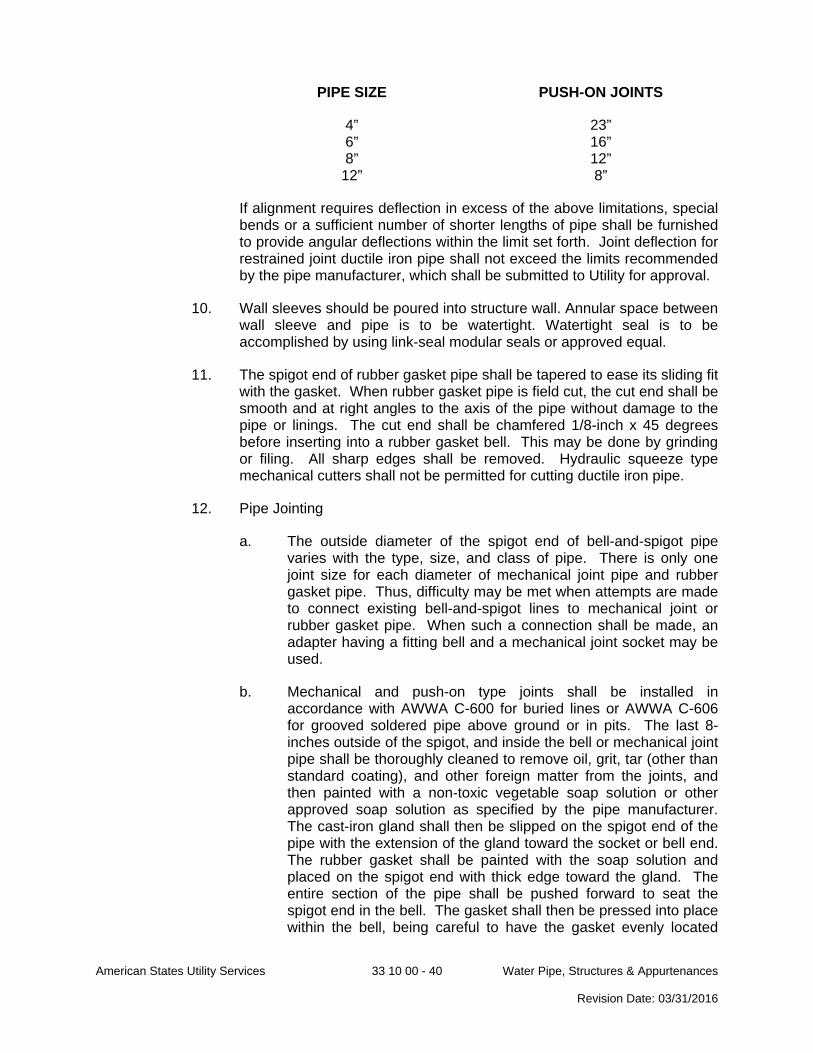
American States Utility Services 33 10 00 - 40 Water Pipe, Structures & Appurtenances Revision Date: 03/31/2016
PIPE SIZE PUSH-ON JOINTS
4” 23” 6” 16” 8” 12”
12” 8”
If alignment requires deflection in excess of the above limitations, special bends or a sufficient number of shorter lengths of pipe shall be furnished to provide angular deflections within the limit set forth. Joint deflection for restrained joint ductile iron pipe shall not exceed the limits recommended by the pipe manufacturer, which shall be submitted to Utility for approval.
10. Wall sleeves should be poured into structure wall. Annular space between wall sleeve and pipe is to be watertight. Watertight seal is to be accomplished by using link-seal modular seals or approved equal.
11. The spigot end of rubber gasket pipe shall be tapered to ease its sliding fit with the gasket. When rubber gasket pipe is field cut, the cut end shall be smooth and at right angles to the axis of the pipe without damage to the pipe or linings. The cut end shall be chamfered 1/8-inch x 45 degrees before inserting into a rubber gasket bell. This may be done by grinding or filing. All sharp edges shall be removed. Hydraulic squeeze type mechanical cutters shall not be permitted for cutting ductile iron pipe.
12. Pipe Jointing
a. The outside diameter of the spigot end of bell-and-spigot pipe varies with the type, size, and class of pipe. There is only one joint size for each diameter of mechanical joint pipe and rubber gasket pipe. Thus, difficulty may be met when attempts are made to connect existing bell-and-spigot lines to mechanical joint or rubber gasket pipe. When such a connection shall be made, an adapter having a fitting bell and a mechanical joint socket may be used.
b. Mechanical and push-on type joints shall be installed in accordance with AWWA C-600 for buried lines or AWWA C-606 for grooved soldered pipe above ground or in pits. The last 8-inches outside of the spigot, and inside the bell or mechanical joint pipe shall be thoroughly cleaned to remove oil, grit, tar (other than standard coating), and other foreign matter from the joints, and then painted with a non-toxic vegetable soap solution or other approved soap solution as specified by the pipe manufacturer. The cast-iron gland shall then be slipped on the spigot end of the pipe with the extension of the gland toward the socket or bell end. The rubber gasket shall be painted with the soap solution and placed on the spigot end with thick edge toward the gland. The entire section of the pipe shall be pushed forward to seat the spigot end in the bell. The gasket shall then be pressed into place within the bell, being careful to have the gasket evenly located

American States Utility Services 33 10 00 - 41 Water Pipe, Structures & Appurtenances Revision Date: 03/31/2016
around the entire joint. The cast-iron gland shall be moved along the pipe into position for bolting, all of the bolts inserted, and the nuts screwed up tightly with the fingers. All nuts shall be tightened with a suitable (preferable torque-limiting) wrench. The torque for various sizes of bolts shall be as follows:
PIPE SIZE BOLT SIZE TORQUE (ft-lbs.)
3” 5/8” 45-60 4”-24” ¾” 75-90
30”-36” 1” 85-100 42”-48” 1¼” 105-120
Nuts spaced 180 degrees apart shall be tightened alternately in order to produce an equal pressure on all parts of the gland.
3.4 JOINT CONSTRUCTION
A. Restrained Joints
1. All plugs, caps, tees, and bends deflecting 11¼ degrees or more, either vertically or horizontally, on mains 6-inches in diameter or larger shall have movement prevented by attaching suitable mechanical joint restraint.
2. Joint restraint for PVC pipe shall be made with bell harnesses.
3. Joint restraint for Ductile Iron pipe shall be made with restrained joint pipe.
4. Concrete blocking for pipe restraint shall be used with specific Utility approval only.
B. Pipe Joints
1. Ductile-Iron Piping, Gasketed Joints for Water-Service Piping shall be made in accordance with AWWA C600 and AWWA M41.
2. Ductile-Iron Piping, Gasketed Joints for Fire-Service-Main Piping shall be made in accordance with UL 194.
3. Ductile-Iron Piping, Grooved Joints for Cut-groove pipe shall be assembled with grooved-end, ductile-iron-piping couplings, gaskets, lubricant, and bolts according to coupling manufacturer's written instructions.
4. PE Piping Insert Fitting Joints shall use plastic insert fittings and fasteners according to fitting manufacturer's written instructions.
5. PVC Piping Gasketed Joints shall use joining materials according to AWWA C900. Construct joints with elastomeric seals and lubricant
American States Utility Services 33 10 00 - 42 Water Pipe, Structures & Appurtenances Revision Date: 03/31/2016
according to ASTM D 2774 or ASTM D 3139 and pipe manufacturer's written instructions.
C. Dissimilar Materials Piping Joints shall be made using adapters compatible with both piping materials, with OD, and with system working pressure.
3.5 FUSIBLE PVC - GENERAL INSTALLATION
A. Fusible C900 pipe shall be used for HDD, water pipe bursting, slip lining through casings and deteriorated water lines and for restrained open cut pipe.
B. Installation guidelines from the pipe supplier shall be followed for all installations.
C. The fusible polyvinylchloride pipe shall be installed in a manner so as not to exceed the recommended bending radius.
D. Where fusible polyvinylchloride pipe is installed by pulling in tension, the recommended Safe Pulling Force established by the pipe supplier shall not be exceeded.
3.6 HDPE GENERAL INSTALLATION
A. Sections of the HDPE pipe shall be joined into continuous lengths on the job site above ground, prior to installation. Pipes shall be jointed to one another and to polyethylene fittings by thermal butt-fusion in accordance with ASTM D 2657 and the manufacturer’s recommendations. Joints between pipe sections shall be smooth on the inside, i.e., the internal bead shall be removed. The tensile strength at yield of the butt-fusion joints shall not be less than the HDPE pipe. Butt-fusion equipment used in the joining procedure shall be capable of meeting all conditions recommended by the pipe manufacturer, including, but not limited to temperature requirements, alignment, and fusion pressures. The joint welding shall be performed by the manufacturer’s representative or the Contractor shall be certified for the butt-fusion by the manufacturer. Suitable polyethylene adaptors shall be provided as required.
B. When performing Horizontal Directional Drilling, caution shall be taken to prevent stretching of the HDPE pipe beyond the elastic limit of the polyethylene. Once the pullback operation has started, the operations shall continue to completion.
C. After installation, a minimum of 24 hours shall be allowed prior to cutting the HDPE, in order for the HDPE pipe to experience stress relief. After the stress relief, the HDPE pipe should be cut in order to install the necessary valves, tees, and fittings as indicated on the drawings.
D. All connections to the HDPE shall be restrained.

American States Utility Services 33 10 00 - 43 Water Pipe, Structures & Appurtenances Revision Date: 03/31/2016
3.7 AERIAL CROSSINGS
A. All construction of aerial crossing shall be in accordance with all requirements of the State Agency having jurisdiction over stream crossings and the Utility.
B. Flanged or restrained joints or a combination of both shall be provided for all aerial pipe crossings, to provide, adequate support to prevent excessive deflection. Supports shall be designed to prevent frost heave, overturning, and settlement.
C. Precautions against freezing, such as insulation and increased slope, shall be provided.
D. Expansion jointing shall be provided between above ground and below ground piping.
E. Where buried water mains change to aerial water mains, special construction techniques shall be used to minimize heaving.
F. For aerial stream crossings, the impact of flood waters and debris shall be considered. The bottom of the pipe should be placed no lower than the elevation of the 25 year flood.
G. Piers, foundations, and/or piles shall be designed by a Licensed or Registered Professional Engineer.
H. Subsurface conditions shall be confirmed by a Licensed or Registered Professional Geotechnical Engineer.
3.8 VALVE INSTALLATION
A. Valves shall be located as shown on plans
B. AWWA Gate Valves installation shall comply with AWWA C600 and AWWA M44. Install each underground valve with stem pointing up and with valve box.
C. UL/FMG, Gate Valves installation shall comply with NFPA 24. Install each underground valve and valves in vaults with stem pointing up and with vertical cast-iron indicator post.
D. Underground Corporation Valves and Curb Valves shall be installed with head pointed up and with a service box.
E. Valves shall be carefully handled, cleaned, and checked for operation prior to backfilling. Stuffing boxes shall be tightened and the valve shall be fully opened and fully closed to insure that all parts are in working condition. Care shall be taken to insure that no dirt, rock, or other obstacles that would interfere with the valve operation are left in the valve.
F. A valve box shall be provided for every valve. The valve box shall be centered and plumb over the wrench nut of the valve. The valve box base shall be set on brick, and arranged that the weight of the valve box and superimposed loads

American States Utility Services 33 10 00 - 44 Water Pipe, Structures & Appurtenances Revision Date: 03/31/2016
shall bear on the base and not on the valve or the pipe. Earth fill shall be carefully tamped around each valve box to a distance of 4-feet on all sides or to undisturbed soil.
G. Combination Air Release Vacuum Valves shall be installed within manholes and on ductile iron pipe, installation on PVC pipe shall not be acceptable unless specifically approved by the Utility.
H. All dead ends on new mains shall have a 2-inch blow-off assembly installed as indicated on the drawings. The blow-off assembly shall be in accordance with Utility standard details.
I. If the distance from the top of the operating nut of valve to finish grade exceeds 4-feet, a valve key extension shall be supplied.
3.9 FIRE HYDRANT INSTALLATION
A. Install Fire Hydrants in accordance with the following:
1. AWWA Fire Hydrants shall comply with AWWA M17.
2. UL/FMG Fire Hydrants shall comply with NFPA 24.
B. Fire hydrants shall be located and installed as shown on the Standard Details.
C. Install each fire hydrant with separate gate valve in supply pipe, anchor with restrained joints or thrust blocks, and support in upright position.
D. Each fire hydrant shall be connected to the main with a 6-inch branch line having at least as much cover as the distribution main.
E. Fire hydrant branches shall have sufficient cover when crossing existing ditches.
F. Hydrants shall be set plumb with pumper nozzle facing roadway.
G. The hydrant branch shall not be backfilled until inspected and approved by the Utility representative.
H. Not less than 7 cubic feet of free draining broken stone or gravel shall be placed around and beneath the waste opening of dry barrel hydrants to ensure drainage.
3.10 WATER METER INSTALLATION
A. Install water meters, piping, and specialties according to Utility’s written instructions.
B. Install water meters 2-inches and smaller, in meter boxes with shutoff valves on water meter inlets. Include valves on water meter outlets and valved bypass around meters unless prohibited by authorities having jurisdiction.

American States Utility Services 33 10 00 - 45 Water Pipe, Structures & Appurtenances Revision Date: 03/31/2016
C. Install water meters 3-inches and larger, in meter vaults. Include shutoff valves on water meter inlets and outlets and valved bypass around meters. Support meters, valves, and piping on brick or concrete piers.
3.11 BACKFLOW PREVENTER INSTALLATION
A. Install backflow preventers of type, size, and capacity indicated, and include valves and test cocks.
B. Install backflow preventers according to requirements of plumbing and health department and authorities having jurisdiction.
C. Do not install backflow preventers that have relief drain in vault or in other spaces subject to flooding.
D. Do not install bypass piping around backflow preventers.
E. Support 2½-inch and larger backflow preventers, valves, and piping near floor and on brick or concrete piers.
F. Assemble and Mount Enclosure for backflow preventer as recommended by the manufacturer and in accordance with the Standard Details. Enclosure shall be installed plumb, level and square.
3.12 WATER METER BOX INSTALLATION
A. Install water meter boxes in accordance with the Standard Details.
3.13 WATER METER VAULT INSTALLATION
A. Install precast concrete vaults according to ASTM C 891 and in accordance with the Standard Details.
B. Water meter vaults shall have an open base with a minimum of 12-inches of #57 stone installed beneath the meter vault.
3.14 THRUST BLOCKING
A. Concrete thrust blocking shall be used only in locations where pipe restraint is not possible or practical, or as directed by the Utility.
B. Where used, concrete for blocking and protection shall be poured in accordance with the following requirements:
1. All fittings, bends, dead ends, etc., shall be acceptably blocked with concrete having bearing on undisturbed earth in the side and/or bottom of the trench.
2. Bearing area shall be equal to that shown on the Plans and greater if deemed necessary by the Utility.
3. No concrete shall be poured or splattered on fitting bells, glands, or bolts.
American States Utility Services 33 10 00 - 46 Water Pipe, Structures & Appurtenances Revision Date: 03/31/2016
C. Concrete for reaction blocking for water mains 12-inches and larger shall be transit-mixed concrete. Concrete shall have a 28 day compressive strength of 3000 p.s.i.
D. Concrete for reaction blocking for water mains less than 12-inches may be composed of bagged 3,000 psi concrete that has been mixed with the correct proportion of water in accordance with the manufacturer’s recommendations.
3.15 IDENTIFICATION
A. Polyethylene Magnetic Tracer Tape
1. Magnetic tracer tape shall be installed continuously along underground pipeline during backfilling of trench.
2. Magnetic tracer tape shall be buried in accordance with the Standard Details and shall be above and parallel to buried nonferrous pipelines.
B. Detectable Identification Wire
1. For the purpose of identification of buried plastic or non-metallic water pipe during future trenching or location, a continuous "detectable" identification wire shall be installed as follows:
a. Wire shall be buried continuously along and above all non-metallic pressure pipelines, not required for gravity pipelines.
b. Wire shall be “stubbed" into valve boxes and secured such that a direct/conductive metal detector may be used to trace the pipe location.
c. Bolts or other approved methods shall be used to secure the detectable wire and the attachment location shall be readily available from finished grade without special equipment.
d. Location inside the valve boxes or other similar structures shall be marked with an approved fluorescent paint for easy identification.
2. Tracer wire test stations shall be provided at no greater than 1000 feet intervals, either in tracer wire access boxes or in in-line mainline valve boxes. Tracer wire access boxes shall be tamper proof and accessible with a standard pentagonal key. The collar and cover shall be cast iron and manufactured in accordance with ASTM a 48 Class 25. The cover shall be lettered “WATER”. Tracer wire shall be attached to the lid by stainless steel terminal bolts.
3.16 CONNECTIONS TO EXISTING PIPE SYSTEMS
A. Approximate locations for existing piping systems are shown in the construction documents. Prior to making connections into existing piping systems, the Contractor shall:
American States Utility Services 33 10 00 - 47 Water Pipe, Structures & Appurtenances Revision Date: 03/31/2016
1. Field verify location, size, piping material and piping system for the existing pipe.
2. Obtain all required fittings, which may include saddles, sleeve type couplings, flanges, tees, or others as shown in the construction documents which are required for making connections.
3. Install all temporary pumps and/or pipes in accordance with established connection plans.
4. Have on hand necessary pipe stoppers, pancake flanges or other items which may be necessary should an existing valve or appurtenance fail to seal properly.
B. Unless otherwise approved by the Utility, new piping systems shall be completely assembled and successfully tested prior to making connections into existing pipe systems.
C. Pipe connections shall be installed per applicable standards and regulations, as well as per the connection manufacturer’s guidelines and as indicated in the construction documents.
D. Use of mechanical joint ductile iron pipe fittings is required for connection to existing water systems, and proper restraint shall be installed as required by the Utility.
E. Fusible PVC shall not be jockeyed into alignment with equipment; rather, DIP fittings shall be used to adjust alignment.
F. The Contractor shall furnish shop drawings showing details of all connection procedures prior to proceeding with the work. Any cutting, re-grouting, and other modifications required to make connections to existing or new pipe shall be incidental to the contract.
G. Tapping For Potable And Non-Potable Water Applications
1. Tapping of water mains shall be done only when it is impracticable to do cut-ins, and shall be specifically approved by the Utility in lieu of a cut-in.
2. Tapping shall be performed using standard tapping saddles designed for use on PVC piping in accordance with AWWA C605. Tapping shall be performed only with use of tap saddles or sleeves. No direct tapping shall be permitted. Tapping shall be performed in accordance with the applicable sections for Saddle Tapping per Uni-Pub-08. When tapping DIP or cast iron pipes, tapping shall be accomplished with a tapping saddle/sleeve that is compatible with existing pipe material.
3. All connections requiring a larger diameter than that recommended by the pipe supplier, shall be made with a pipe connection as specified and indicated on the drawings.
4. Equipment used for tapping shall be made specifically for the pipe material to be tapped.
American States Utility Services 33 10 00 - 48 Water Pipe, Structures & Appurtenances Revision Date: 03/31/2016
5. Taps may be performed while the pipeline is filled with water and under pressure (‘wet’ tap), or when the pipeline is not filled with water and not under pressure (‘dry’ tap).
6. Wet taps shall not be allowed when the water main to be tapped is the same diameter as the connecting line, unless approved in writing by Utility.
3.17 IRRIGATION SYSTEMS
A. A separate service connection is required for all irrigation systems (see section regarding Connections to Existing Systems.) Under no circumstance shall an irrigation system be connected to any other water service line whether domestic or fire supply.
B. A Utility approved water meter and backflow preventer shall be installed on all irrigation service lines.
C. A shut off valve shall be installed between the meter and the service tap.
3.18 HYDROSTATIC TESTS
A. Water mains shall be tested in accordance with AWWA C600 for DIP mains and AWWA C605 for PVC mains.
B. After the pipe has been laid and partially backfilled as specified, all newly laid pipe, or any valved section thereof shall be subjected to a hydrostatic pressure test and leakage test. Each valved section shall be tested individually.
C. The pipeline shall be fully restrained prior to pressurization. This includes complete installation of all mechanical restraints per the restraint manufacturer’s guidelines. All appurtenances included in the pressure test, including valves, blow-offs, and air-relief valves shall be checked for proper installation and restraint prior to the beginning of the test. Where any section of a water line is provided with concrete thrust blocking for fittings or hydrants, the hydrostatic test shall not be made until at least five days after installation of the blocking unless otherwise approved.
D. The Contractor shall furnish all labor and material, including test pumps, taps, and corporations, for completing hydrostatic tests
E. A Utility representative shall be present and shall open and close any valves on the current water system. Under no circumstances, shall a Contractor tamper with or operate any valves not installed by him.
F. The Contractor shall submit to the Utility for approval, a proposed method for disposing of the test water from the system.
G. The duration of the pressure test shall be a minimum of two hours, as directed by the Utility Representative. All water mains shall be tested at a hydrostatic pressure of 200 psi. Each valved section of pipe shall be slowly filled with water applied by means of a pump connected to the pipe in a manner satisfactory to

American States Utility Services 33 10 00 - 49 Water Pipe, Structures & Appurtenances Revision Date: 03/31/2016
the Utility. When testing a valved section, pressure should be applied to adjacent sections so that the disc differential across the gate valves at each end of the section shall not exceed 150 psi. Before applying the specified test pressure, all air shall be expelled from the pipe. If hydrants or blow offs are not available at the high places, taps shall not be made to provide blow offs.
H. The quantity of water supplied to the newly laid pipe in order to maintain the leakage pressure shall be measured. The allowable leakage in gallons per hour per 1,000 ft of pipe is as follows:
SIZE: 4” 6” 8” 12” 16” 20” 24” 30” 36”
LEAKAGE: 0.38 0.57 0.76 1.15 1.53 1.91 2.29 2.87 3.44
I. The results of pressure tests, leakage tests, and disinfection shall be satisfactory as specified. All replacement, repair or retesting shall be accomplished by the Contractor at no additional cost to the Utility.
J. If water is lost when treated for disinfection and air is admitted to the unit being tested, or if any repair procedure results in contamination of the unit, disinfection shall be re-accomplished.
K. Contractor shall submit all pressure and leakage testing results and reports to Utility for approval.
3.19 DISINFECTION
A. The Contractor shall perform and furnish all chlorinating equipment, disinfection solution, materials, excavation, barricades, backfilling, and any taps and corporations necessary for sterilization and testing procedures outlined in this specification.
B. Disinfection and testing shall be in accordance with State Requirements. The Contractor shall cooperate with the Utility representative and furnish any needed assistance, and schedule the testing with the Utility's representative.
C. Water distribution mains, after flushing to remove sediment and other foreign matter, and after testing for leaks, shall be disinfected by the addition and thorough dispersion of a chlorine solution in concentrations sufficient to produce a chlorine residual of at least 50 milligrams per liter (or ppm) in the water throughout the distribution system. In no case shall the agent be introduced into the lines in a dry solid state.
D. The Contractor shall take all necessary measures to prevent downstream erosion caused by flushing the lines.
E. The chlorine solutions shall remain in contact with interior surfaces of the water system for a period of 24 hours and shall produce not less than 10 ppm of chlorine throughout the line at the end of the retention period. All valves on the lines being disinfected shall be opened and closed several times during the contact period.

American States Utility Services 33 10 00 - 50 Water Pipe, Structures & Appurtenances Revision Date: 03/31/2016
F. The 24 hour period of contact, the water system shall be flushed with fresh water from an approved water source until the chlorine solution is dispelled. During the flushing period, each fire hydrant on the line shall be opened and closed several times.
G. Upon completion of disinfection, the water line shall be refilled with water and samples collected for bacteriological examination. Generally, a sample shall be taken every 2,000 feet for distribution lines and every 4,000 feet on transmission lines. Samples may be taken at new service connections, at air valve stations, or through any other connection to the line 1-inch or smaller in diameter. Samples shall not be taken at fire hydrants without the specific approval of the Utility. The samples shall be taken in standard sterilized bacteria sample bottles marked with the sample location provided by contractor. Samples shall be taken in the presence of a Utility representative. The contractor shall take samples to a Utility approved laboratory for analysis. Results of the analyses shall be furnished to Utility.
H. The disinfection shall be repeated until tests indicate the absence of pollution for at least two full days. If the initial sample taken after disinfection and flushing does not indicate that the water main is sterilized, the Contractor shall, in conjunction with Utility, flush the lines. Once flushing is complete, another sample shall be taken to the Utility appointed laboratory for analysis. Should this second sample also fail to indicate that the main is disinfected; the Contractor shall disinfect the main and resample. This process shall be repeated until the samples are satisfactory.
3.20 WATER MAIN AND SERVICE REMOVAL OR ABANDONMENT
A. Services – Contractors abandoning water services shall remove the entire service including the corporation cock and insert a plug at the main. If approved by Utility, the Contractor may close the corporation cock, cap the service line, and encase the plug with one cubic foot of concrete. All remaining portions of the service shall be removed from the main to within ten feet of the building, and shall be disposed of properly.
B. Mains – Water main abandonment shall be performed in accordance with a plan approved by Utility. Any water abandonment and method of abandonment shall be noted on Construction drawings and As-Built drawings.
1. All work shall be coordinated with Utility.
2. Abandon existing water mains after new water main and its hydrants are placed in service and all services on the main to be abandoned have been transferred to the new main.
3. Coordinate with Utility for shut down of existing water mains for each water main abandonment location.
4. Have all labor, equipment and materials on site for all water main abandonments. Excavate water main to be abandoned at points of abandonment.
American States Utility Services 33 10 00 - 51 Water Pipe, Structures & Appurtenances Revision Date: 03/31/2016
5. The Contractor shall abandon the existing water main via dig and removal. Abandonment in place via flow able fill shall be approved in writing by Utility.
6. Backfill abandonment excavation and restore disturbed areas to original condition
7. Asbestos containing underground piping and appurtenances may be present on the project site and may not accessible for sampling. If suspect materials are discovered during excavation, the excavation activities shall immediately stop. A State accredited asbestos inspector shall sample the suspect material, and determine the proper method of disposal. The accredited asbestos inspector shall supervise the handling of all asbestos containing materials until those materials are disposed of properly.
8. Tee Connection Abandonment
a. Remove tee, tapping sleeve and valve or other connecting fitting with three (3) separate pipe cuts.
b. Cut out a minimum of 36-inches of pipe on water main that is to remain in service. Extend cuts, if necessary, along water main to remain in service so that no existing pipe joint shall be within 24-inches of a coupling.
c. The existing water main shall be sleeved and repaired following abandonment of the water line.
d. The water main shall be disinfected and activated by the Contractor and accepted by Utility prior to backfill.
9. In-Line Main Abandonment.
a. At the point of abandonment, cut a maximum of 36-inches of pipe.
b. Install a plug, 2-inch tap, and new 2-inch valve and blow-off on the new dead end water main.
c. Install thrust blocking or restraint as needed to secure the existing water main.
d. The water main to be abandoned shall be abandoned as indicated on the drawings.
e. Install concrete thrust block around timber to dimensions which meet the required undisturbed soil bearing area as set forth in the typical detail.
3.21 CLEANUP AND REPAIR
American States Utility Services 33 10 00 - 52 Water Pipe, Structures & Appurtenances Revision Date: 03/31/2016
A. The Contractor shall maintain its operations in a neat and orderly manner causing as little inconvenience as possible. Within 7 working days from the time the trench was opened, all roadside ditches, culverts, etc., shall be repaired and surfaces thoroughly cleaned. All excess excavation shall be removed from the trench side and disposed of at the Contractor's expense. The work area shall then be thoroughly cleaned.
3.22 INSPECTION AND ACCEPTANCE
A. All work shall be subject to inspection and approval by Utility prior to final acceptance.
B. The installed pipe shall meet the following criteria for acceptance:
1. No more than 12-inch horizontal deviation from design location shall be permitted in the position of the product pipe.
2. If the initial bore deviates from the design line or grade by amounts greater than that specified, return the pipe to design line or grade as required by the Utility.
3. If either pipe is off design line or grade by an amount that requires redesign and/or correction of the pipeline or associated structures, the Contractor shall do so at no additional cost to Utility.
4. Walkover centerline alignment to verify alignment and grade.
C. Final acceptance of the pipe shall be based on the above criteria; and shall be contingent upon all pressure and leakage tests yielding satisfactory results, submittal of accurate as-built plans, and the Utility’s review of the results of testing.
D. Final acceptance of the project shall not be made until the Contractor has completed the total project, restoration, and cleanup have been performed to the satisfaction of the Utility and all closeout documents have been submitted. Restoration and cleanup includes the acceptance and release of the NPDES Permit by State Agency responsible for NPDES permits.
END OF SECTION 33 10 00