32m-05001—01 - gas electro-mechanical valves · 2,carbon steel 1172 50 10 2, 4 5, stainless steel...
TRANSCRIPT
TECHNICAL CATALOG
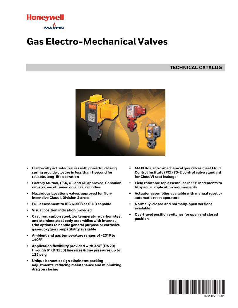
Gas Electro-Mechanical Valves
• Electrically actuated valves with powerful closing spring provide closure in less than 1 second for reliable, long-life operation
• Factory Mutual, CSA, UL and CE approved; Canadian registration obtained on all valve bodies
• Hazardous Locations valves approved for Non-incendive Class I, Division 2 areas
• Full assessment to IEC 61508 as SIL 3 capable
• Visual position indication provided
• Cast iron, carbon steel, low temperature carbon steel and stainless steel body assemblies with internal trim options to handle general purpose or corrosive gases; oxygen compatibility available
• Ambient and gas temperature ranges of -20°F to 140°F
• Application flexibility provided with 3/4” (DN20) through 6” (DN150) line sizes & line pressures up to 125 psig
• Unique bonnet design eliminates packing adjustments, reducing maintenance and minimizing drag on closing
• MAXON electro-mechanical gas valves meet Fluid Control Institute (FCI) 70-2 control valve standard for Class VI seat leakage
• Field rotatable top assemblies in 90° increments to fit specific application requirements
• Actuator assemblies available with manual reset or automatic reset operators
• Normally-closed and normally-open versions available
• Overtravel position switches for open and closed position
32M-05001-01
GAS ELECTRO-MECHANICAL VALVES
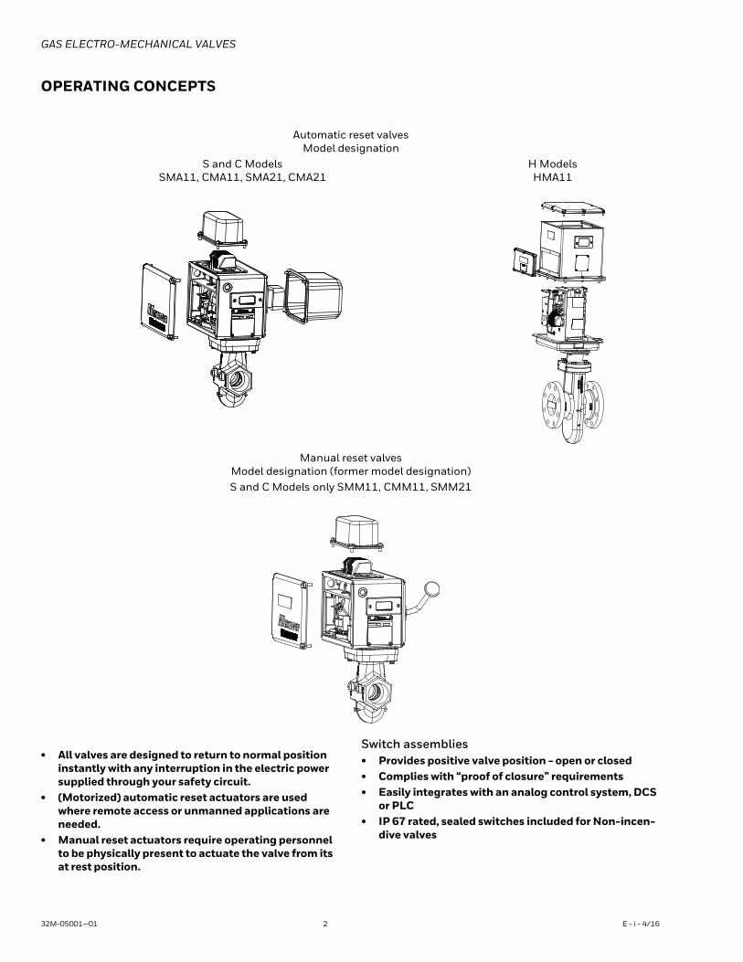
OPERATING CONCEPTS
• All valves are designed to return to normal position instantly with any interruption in the electric power supplied through your safety circuit.
• (Motorized) automatic reset actuators are used where remote access or unmanned applications are needed.
• Manual reset actuators require operating personnel to be physically present to actuate the valve from its at rest position.
Switch assemblies• Provides positive valve position - open or closed• Complies with “proof of closure” requirements• Easily integrates with an analog control system, DCS
or PLC• IP 67 rated, sealed switches included for Non-incen-
dive valves
Automatic reset valvesModel designation
S and C ModelsSMA11, CMA11, SMA21, CMA21
H ModelsHMA11
Manual reset valvesModel designation (former model designation)S and C Models only SMM11, CMM11, SMM21
32M-05001—01 2 E - i - 4/16
GAS ELECTRO-MECHANICAL VALVES
Body and trim selections
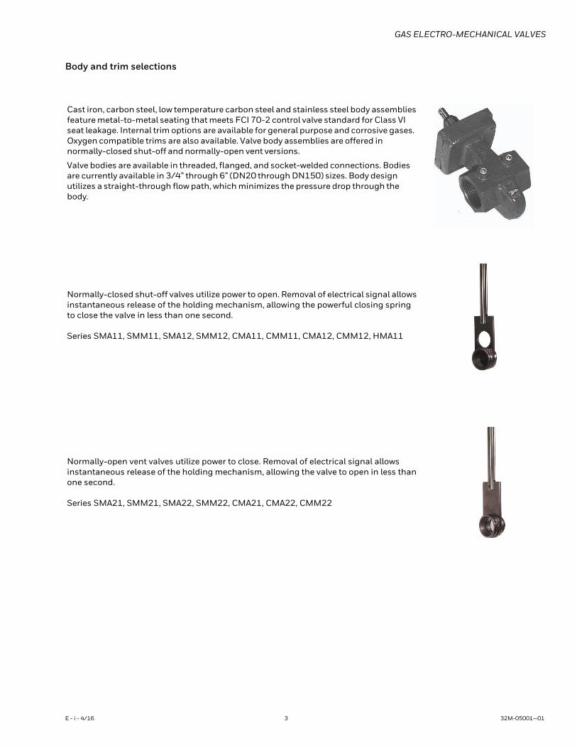
Cast iron, carbon steel, low temperature carbon steel and stainless steel body assemblies feature metal-to-metal seating that meets FCI 70-2 control valve standard for Class VI seat leakage. Internal trim options are available for general purpose and corrosive gases. Oxygen compatible trims are also available. Valve body assemblies are offered in normally-closed shut-off and normally-open vent versions.
Valve bodies are available in threaded, flanged, and socket-welded connections. Bodies are currently available in 3/4” through 6” (DN20 through DN150) sizes. Body design utilizes a straight-through flow path, which minimizes the pressure drop through the body.
Normally-closed shut-off valves utilize power to open. Removal of electrical signal allows instantaneous release of the holding mechanism, allowing the powerful closing spring to close the valve in less than one second.
Series SMA11, SMM11, SMA12, SMM12, CMA11, CMM11, CMA12, CMM12, HMA11
Normally-open vent valves utilize power to close. Removal of electrical signal allows instantaneous release of the holding mechanism, allowing the valve to open in less than one second.
Series SMA21, SMM21, SMA22, SMM22, CMA21, CMA22, CMM22
E - i - 4/16 3 32M-05001—01
GAS ELECTRO-MECHANICAL VALVES
Agency approvals and certifications
Valve cycle requirements
This is based on the standards that MAXON valves are approved to and the corresponding minimum number of cycles to be completed without failure as shown in the chart below.
General Purpose ValvesSMA11, SMM11, CMA11, CMM11, SMA21, SMM21,
CMA21, HMA11
Non-incendive/Non-sparking ValvesSMA12, SMM12, SMA22, CMA22,
CMA12, CMM12, SMM22, CMM22
Standards Markings Standards Markings
FM approvals FM 7400
FM 7400FM 3611FM 3600FM 3810
Class I, Div. 2, Groups ABCDClass II, Div. 2, Groups FGClass III, Div. 2 Temp Code T4 (AC) T3 (DC, sizes 3/4” - 1-1/2”) T3C (DC, sizes 2”-6”)
FM approvals - IEC Ex Certification Not applicable IEC 60079-0
IEC 60079-15
Ex nA nC IIC T4A (AC), T3 (DC), Ta=60°C GcEx tc IIIC T135°C Dc IP65FMG 11.0032X
UL approvals UL 429 Not applicable Not applicable
CSA International CSA 6.5 CSA 6.5CSA 22.2 No. 213
Class I, Div. 2, Groups ABCDClass II, Div. 2, Groups FGClass III, Div. 2 Temp Code T4 (AC) T3 (DC)
European approvals [1] EN 161EN 13774
CL/KL: A, GR 2EC PIN: C87BQ83 Not applicable Not applicable
IEC approvals IEC 61508 None IEC 61508 None
KTL approvals None None Not applicable
MA12: 12-KB4BO-0057MM12: 13-KB4BO-0419MA22: 16-KA4BO-0027MM22: 16-K4BO-0028
AGA Certifications AS 4629 (CLASS 1) None AS 4629 None
[1] Product certified to meet the following (SMA11, CMA11, SMM11, CMM11, SMA21,CMA21, SMM21 only):Gas Appliance Directive (2009/142/EC)Low Voltage Directive (2014/35/EU)EMC Directive (2014/30/EU)Pressure Equipment Directive (2014/68/EU) up to 4"
ListedGeneral Purpose
628A
(Normally open valves)
ListedSafety
Shut-offf 628A
(Normally open valves)
C/I C/I
UL (UL 429) CSA (CSA 6.5) FM (FM 7400) European (EN161)
AutomaticSeries MA11, MA12 100,000 100,000 20,000
<= 1” 200,000<= 3” 100,000<= 6” 50,000
ManualSeries MM11, MM12 6,000 20,000 20,000 No special
requirementsVent valvesSeries MA21, MA22, MM21, MM22 6,000 No special
requirementsNo special
requirementsNo special
requirements
32M-05001—01 4 E - i - 4/16
GAS ELECTRO-MECHANICAL VALVES
VALVE MODEL NUMBER DESCRIPTION
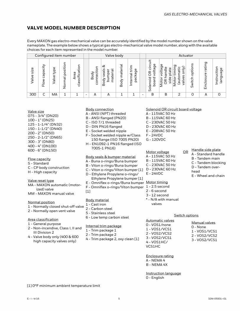
Every MAXON gas electro-mechanical valve can be accurately identified by the model number shown on the valve nameplate. The example below shows a typical gas electro-mechanical valve model number, along with the available choices for each item represented in the model number.
[1] 0°F minimum ambient temperature limit
Configured item number Valve body Actuator
Valv
e si
ze
Flow
cap
acit
y
Valv
e ty
pe
Nor
mal
pos
itio
n
Are
acl
assi
fica
tion
Bod
yco
nn
ecti
on
Bod
y se
als
&bu
mpe
rm
ater
ial
Bod
y m
ater
ial
Inte
rnal
trim
pack
age
Sol
enoi
d O
R c
ircu
it b
oard
vol
tage
Mot
or v
olta
geO
R h
andl
esi
de p
late
Mot
or ti
min
g(a
utom
atic
valv
es o
nly
)
Sw
itch
opt
ion
s
En
clos
ure
rati
ng
Inst
ruct
ion
lan
guag
e
300 C MA 1 1 - A A 1 1 - B B 2 0 A 0
Valve size075 - 3/4” (DN20)100 - 1” (DN25)125 - 1-1/4” (DN32)150 - 1-1/2” (DN40)200 - 2” (DN50)250 - 2-1/2” (DN65)300 - 3” (DN80)400 - 4” (DN100)600 - 6” (DN150)
Flow capacityS - StandardC - CP body constructionH - High capacity
Valve reset typeMA - MAXON automatic (motor-
ized) valveMM - MAXON manual valve
Normal position1 - Normally closed shut-off valve2 - Normally open vent valve
Area classification1 - General purpose2 - Non-incendive, Class I, II and
III Division 24 - Valve body only (400 & 600
high capacity valves only)
Body connectionA - ANSI (NPT) threadedB - ANSI flanged (PN20)C - ISO 7/1 threadedD - DIN PN16 flangedE - Socket welded nippleF - Socket welded nipple w/Class
150 flange (ISO 7005 PN20)H - EN1092-1 PN16 flanged (ISO
7005-1 PN16)
Body seals & bumper materialA - Buna o-rings/Buna bumperB - Viton o-rings/Buna bumperC - Viton o-rings/Viton bumper [1]D - Ethylene Propylene o-rings/
Ethylene Propylene bumper [1]E - Omniflex o-rings/Buna bumperF - Omniflex o-rings/Viton bumper [1]
Body material1 - Cast iron2 - Carbon steel5 - Stainless steel6 - Low temp carbon steel
Internal trim package1 - Trim package 12 - Trim package 24 - Trim package 2, oxy clean [1]
Solenoid OR circuit board voltageA - 115VAC 50 HzB - 115VAC 60 HzC - 230VAC 50 HzD - 230VAC 60 HzE - 208VAC 50 HzF - 24VDCG - 120VDC
Motor voltageA - 115VAC 50 HzB - 115VAC 60 HzC - 230VAC 50 HzD - 230VAC 60 HzE - 24VDC
Motor timing1 - 2.5 second2 - 6 second3 - 12 second* - N/A with manual
valves
OR Handle side plateA - Standard handleB - Tandem mainC - Tandem blockingD - Tandem over-headE - Wheel and chain
Switch optionsAutomatic valves0 - VOS1/none1 - VOS1/VCS12 - VOS2/VCS23 - VOS2/VCS14 - VOS1HC/VCS1HC
Manual valves0 - None1 - VOS1/VCS12 - VOS2/VCS23 - VOS2/VCS1
Enclosure ratingA - NEMA 4B - NEMA 4X
Instruction language0 - English
E - i - 4/16 5 32M-05001—01
GAS ELECTRO-MECHANICAL VALVES
VALVE MODEL CROSS REFERENCE
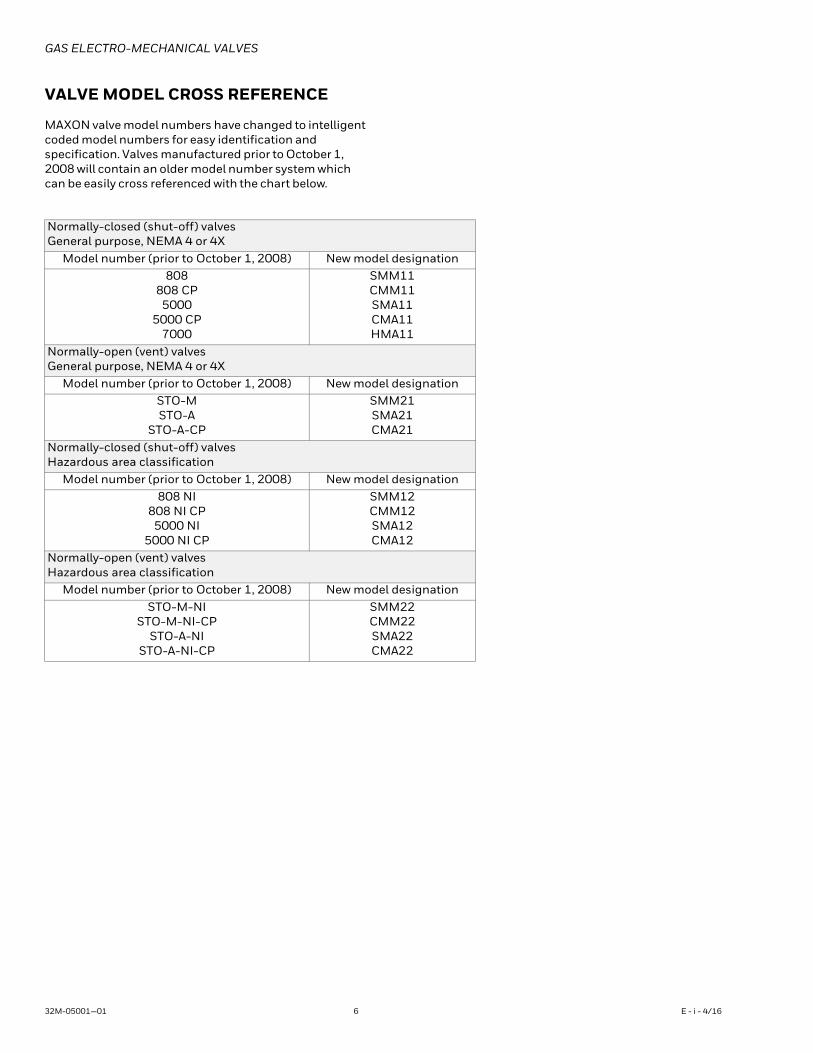
MAXON valve model numbers have changed to intelligent coded model numbers for easy identification and specification. Valves manufactured prior to October 1, 2008 will contain an older model number system which can be easily cross referenced with the chart below.
Normally-closed (shut-off) valvesGeneral purpose, NEMA 4 or 4X
Model number (prior to October 1, 2008) New model designation808
808 CP5000
5000 CP7000
SMM11CMM11SMA11CMA11HMA11
Normally-open (vent) valvesGeneral purpose, NEMA 4 or 4X
Model number (prior to October 1, 2008) New model designationSTO-MSTO-A
STO-A-CP
SMM21SMA21CMA21
Normally-closed (shut-off) valvesHazardous area classification
Model number (prior to October 1, 2008) New model designation808 NI
808 NI CP5000 NI
5000 NI CP
SMM12CMM12SMA12CMA12
Normally-open (vent) valvesHazardous area classification
Model number (prior to October 1, 2008) New model designationSTO-M-NI
STO-M-NI-CPSTO-A-NI
STO-A-NI-CP
SMM22CMM22SMA22CMA22
32M-05001—01 6 E - i - 4/16
GAS ELECTRO-MECHANICAL VALVES
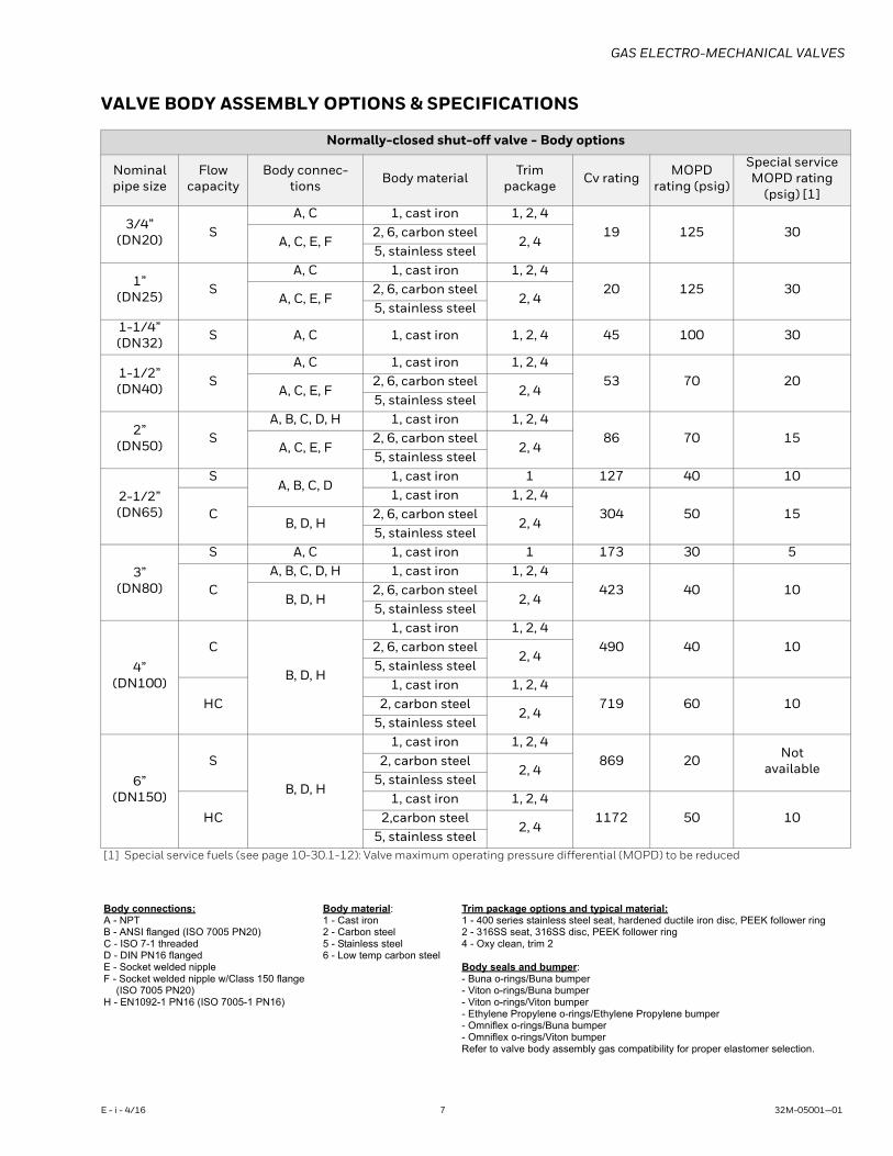
VALVE BODY ASSEMBLY OPTIONS & SPECIFICATIONS
Normally-closed shut-off valve - Body options
Nominal pipe size
Flow capacity
Body connec-tions Body material Trim
package Cv rating MOPD rating (psig)
Special service MOPD rating
(psig) [1]
3/4” (DN20) S
A, C 1, cast iron 1, 2, 419 125 30
A, C, E, F2, 6, carbon steel
2, 45, stainless steel
1” (DN25) S
A, C 1, cast iron 1, 2, 420 125 30
A, C, E, F2, 6, carbon steel
2, 45, stainless steel
1-1/4” (DN32) S A, C 1, cast iron 1, 2, 4 45 100 30
1-1/2”(DN40) S
A, C 1, cast iron 1, 2, 453 70 20
A, C, E, F2, 6, carbon steel
2, 45, stainless steel
2”(DN50) S
A, B, C, D, H 1, cast iron 1, 2, 486 70 15
A, C, E, F2, 6, carbon steel
2, 45, stainless steel
2-1/2”(DN65)
SA, B, C, D
1, cast iron 1 127 40 10
C1, cast iron 1, 2, 4
304 50 15B, D, H
2, 6, carbon steel2, 4
5, stainless steel
3”(DN80)
S A, C 1, cast iron 1 173 30 5
CA, B, C, D, H 1, cast iron 1, 2, 4
423 40 10B, D, H
2, 6, carbon steel2, 4
5, stainless steel
4”(DN100)
C
B, D, H
1, cast iron 1, 2, 4490 40 102, 6, carbon steel
2, 45, stainless steel
HC1, cast iron 1, 2, 4
719 60 102, carbon steel2, 4
5, stainless steel
6”(DN150)
S
B, D, H
1, cast iron 1, 2, 4869 20 Not
available2, carbon steel2, 4
5, stainless steel
HC1, cast iron 1, 2, 4
1172 50 102,carbon steel2, 4
5, stainless steel[1] Special service fuels (see page 10-30.1-12): Valve maximum operating pressure differential (MOPD) to be reduced
Body connections:A - NPTB - ANSI flanged (ISO 7005 PN20)C - ISO 7-1 threadedD - DIN PN16 flangedE - Socket welded nippleF - Socket welded nipple w/Class 150 flange
(ISO 7005 PN20)H - EN1092-1 PN16 (ISO 7005-1 PN16)
Body material:1 - Cast iron2 - Carbon steel5 - Stainless steel6 - Low temp carbon steel
Trim package options and typical material:1 - 400 series stainless steel seat, hardened ductile iron disc, PEEK follower ring2 - 316SS seat, 316SS disc, PEEK follower ring4 - Oxy clean, trim 2
Body seals and bumper:- Buna o-rings/Buna bumper- Viton o-rings/Buna bumper- Viton o-rings/Viton bumper- Ethylene Propylene o-rings/Ethylene Propylene bumper- Omniflex o-rings/Buna bumper- Omniflex o-rings/Viton bumperRefer to valve body assembly gas compatibility for proper elastomer selection.
E - i - 4/16 7 32M-05001—01
GAS ELECTRO-MECHANICAL VALVES
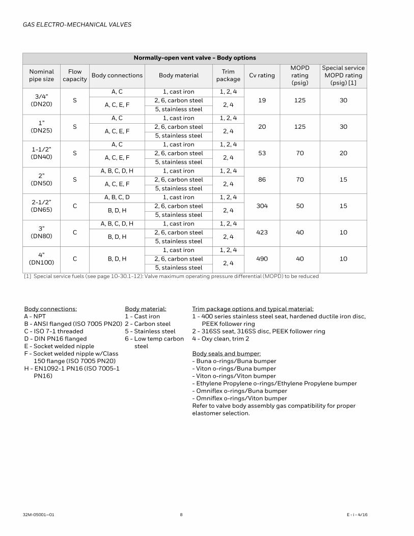
Normally-open vent valve - Body options
Nominalpipe size
Flowcapacity Body connections Body material Trim
package Cv ratingMOPDrating(psig)
Special serviceMOPD rating
(psig) [1]
3/4” (DN20) S
A, C 1, cast iron 1, 2, 419 125 30
A, C, E, F2, 6, carbon steel
2, 45, stainless steel
1”(DN25) S
A, C 1, cast iron 1, 2, 420 125 30
A, C, E, F2, 6, carbon steel
2, 45, stainless steel
1-1/2”(DN40) S
A, C 1, cast iron 1, 2, 453 70 20
A, C, E, F2, 6, carbon steel
2, 45, stainless steel
2”(DN50) S
A, B, C, D, H 1, cast iron 1, 2, 486 70 15
A, C, E, F2, 6, carbon steel
2, 45, stainless steel
2-1/2”(DN65) C
A, B, C, D 1, cast iron 1, 2, 4304 50 15
B, D, H2, 6, carbon steel
2, 45, stainless steel
3”(DN80) C
A, B, C, D, H 1, cast iron 1, 2, 4423 40 10
B, D, H2, 6, carbon steel
2, 45, stainless steel
4”(DN100) C B, D, H
1, cast iron 1, 2, 4490 40 102, 6, carbon steel
2, 45, stainless steel
[1] Special service fuels (see page 10-30.1-12): Valve maximum operating pressure differential (MOPD) to be reduced
Body connections:A - NPTB - ANSI flanged (ISO 7005 PN20)C - ISO 7-1 threadedD - DIN PN16 flangedE - Socket welded nippleF - Socket welded nipple w/Class
150 flange (ISO 7005 PN20)H - EN1092-1 PN16 (ISO 7005-1
PN16)
Body material:1 - Cast iron2 - Carbon steel5 - Stainless steel6 - Low temp carbon
steel
Trim package options and typical material:1 - 400 series stainless steel seat, hardened ductile iron disc,
PEEK follower ring2 - 316SS seat, 316SS disc, PEEK follower ring4 - Oxy clean, trim 2
Body seals and bumper:- Buna o-rings/Buna bumper- Viton o-rings/Buna bumper- Viton o-rings/Viton bumper- Ethylene Propylene o-rings/Ethylene Propylene bumper- Omniflex o-rings/Buna bumper- Omniflex o-rings/Viton bumperRefer to valve body assembly gas compatibility for proper elastomer selection.
32M-05001—01 8 E - i - 4/16
GAS ELECTRO-MECHANICAL VALVES
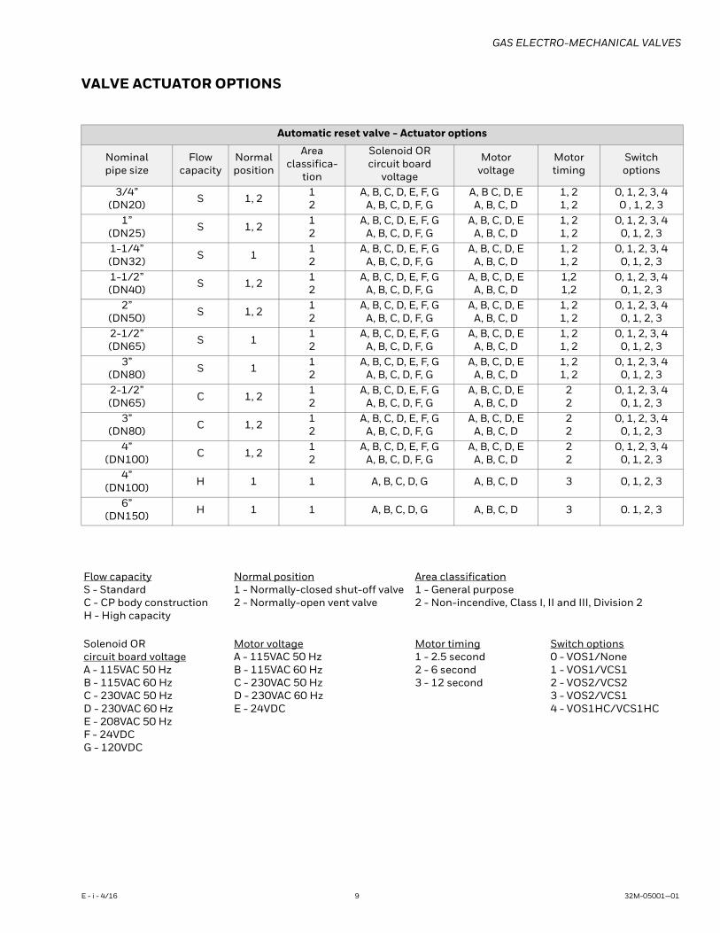
VALVE ACTUATOR OPTIONS
Automatic reset valve - Actuator options
Nominal pipe size
Flowcapacity
Normal position
Areaclassifica-
tion
Solenoid ORcircuit board
voltage
Motorvoltage
Motortiming
Switchoptions
3/4” (DN20) S 1, 2 1
2A, B, C, D, E, F, G
A, B, C, D, F, GA, B C, D, EA, B, C, D
1, 21, 2
0, 1, 2, 3, 40 , 1, 2, 3
1” (DN25) S 1, 2 1
2A, B, C, D, E, F, G
A, B, C, D, F, GA, B, C, D, E
A, B, C, D1, 21, 2
0, 1, 2, 3, 40, 1, 2, 3
1-1/4”(DN32) S 1 1
2A, B, C, D, E, F, G
A, B, C, D, F, GA, B, C, D, E
A, B, C, D1, 21, 2
0, 1, 2, 3, 40, 1, 2, 3
1-1/2”(DN40) S 1, 2 1
2A, B, C, D, E, F, G
A, B, C, D, F, GA, B, C, D, E
A, B, C, D1,21,2
0, 1, 2, 3, 40, 1, 2, 3
2”(DN50) S 1, 2 1
2A, B, C, D, E, F, G
A, B, C, D, F, GA, B, C, D, E
A, B, C, D1, 21, 2
0, 1, 2, 3, 40, 1, 2, 3
2-1/2”(DN65) S 1 1
2A, B, C, D, E, F, G
A, B, C, D, F, GA, B, C, D, E
A, B, C, D1, 21, 2
0, 1, 2, 3, 40, 1, 2, 3
3”(DN80) S 1 1
2A, B, C, D, E, F, G
A, B, C, D, F, GA, B, C, D, E
A, B, C, D1, 21, 2
0, 1, 2, 3, 40, 1, 2, 3
2-1/2”(DN65) C 1, 2 1
2A, B, C, D, E, F, G
A, B, C, D, F, GA, B, C, D, E
A, B, C, D22
0, 1, 2, 3, 40, 1, 2, 3
3”(DN80) C 1, 2 1
2A, B, C, D, E, F, G
A, B, C, D, F, GA, B, C, D, E
A, B, C, D22
0, 1, 2, 3, 40, 1, 2, 3
4”(DN100) C 1, 2 1
2A, B, C, D, E, F, G
A, B, C, D, F, GA, B, C, D, E
A, B, C, D22
0, 1, 2, 3, 40, 1, 2, 3
4”(DN100) H 1 1 A, B, C, D, G A, B, C, D 3 0, 1, 2, 3
6”(DN150) H 1 1 A, B, C, D, G A, B, C, D 3 0. 1, 2, 3
Flow capacityS - StandardC - CP body constructionH - High capacity
Normal position1 - Normally-closed shut-off valve2 - Normally-open vent valve
Area classification1 - General purpose2 - Non-incendive, Class I, II and III, Division 2
Solenoid ORcircuit board voltageA - 115VAC 50 HzB - 115VAC 60 HzC - 230VAC 50 HzD - 230VAC 60 HzE - 208VAC 50 HzF - 24VDCG - 120VDC
Motor voltageA - 115VAC 50 HzB - 115VAC 60 HzC - 230VAC 50 HzD - 230VAC 60 HzE - 24VDC
Motor timing1 - 2.5 second2 - 6 second3 - 12 second
Switch options0 - VOS1/None1 - VOS1/VCS12 - VOS2/VCS23 - VOS2/VCS14 - VOS1HC/VCS1HC
E - i - 4/16 9 32M-05001—01
GAS ELECTRO-MECHANICAL VALVES
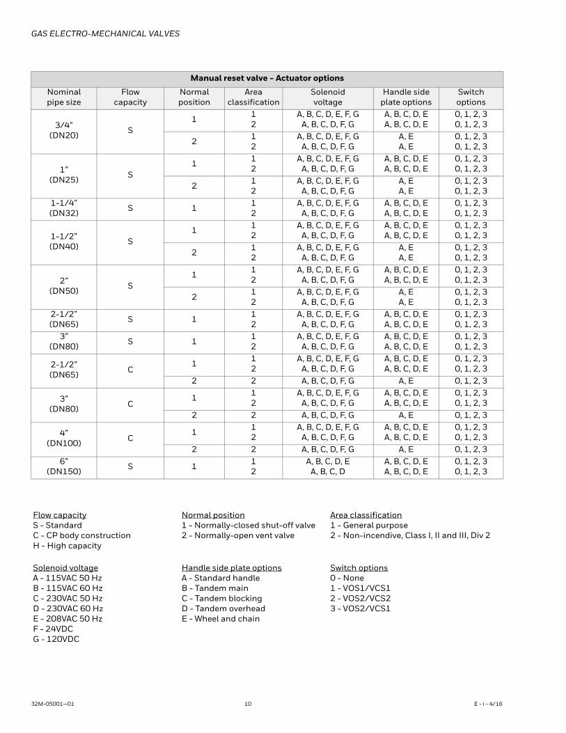
Manual reset valve - Actuator options
Nominalpipe size
Flowcapacity
Normal position
Areaclassification
Solenoidvoltage
Handle sideplate options
Switchoptions
3/4”(DN20) S
1 12
A, B, C, D, E, F, GA, B, C, D, F, G
A, B, C, D, EA, B, C, D, E
0, 1, 2, 30, 1, 2, 3
2 12
A, B, C, D, E, F, GA, B, C, D, F, G
A, EA, E
0, 1, 2, 30, 1, 2, 3
1”(DN25) S
1 12
A, B, C, D, E, F, GA, B, C, D, F, G
A, B, C, D, EA, B, C, D, E
0, 1, 2, 30, 1, 2, 3
2 12
A, B, C, D, E, F, GA, B, C, D, F, G
A, EA, E
0, 1, 2, 30, 1, 2, 3
1-1/4”(DN32) S 1 1
2A, B, C, D, E, F, G
A, B, C, D, F, GA, B, C, D, EA, B, C, D, E
0, 1, 2, 30, 1, 2, 3
1-1/2”(DN40) S
1 12
A, B, C, D, E, F, GA, B, C, D, F, G
A, B, C, D, EA, B, C, D, E
0, 1, 2, 30, 1, 2, 3
2 12
A, B, C, D, E, F, GA, B, C, D, F, G
A, EA, E
0, 1, 2, 30, 1, 2, 3
2”(DN50) S
1 12
A, B, C, D, E, F, GA, B, C, D, F, G
A, B, C, D, EA, B, C, D, E
0, 1, 2, 30, 1, 2, 3
2 12
A, B, C, D, E, F, GA, B, C, D, F, G
A, EA, E
0, 1, 2, 30, 1, 2, 3
2-1/2”(DN65) S 1 1
2A, B, C, D, E, F, G
A, B, C, D, F, GA, B, C, D, EA, B, C, D, E
0, 1, 2, 30, 1, 2, 3
3”(DN80) S 1 1
2A, B, C, D, E, F, G
A, B, C, D, F, GA, B, C, D, EA, B, C, D, E
0, 1, 2, 30, 1, 2, 3
2-1/2”(DN65) C
1 12
A, B, C, D, E, F, GA, B, C, D, F, G
A, B, C, D, EA, B, C, D, E
0, 1, 2, 30, 1, 2, 3
2 2 A, B, C, D, F, G A, E 0, 1, 2, 3
3”(DN80) C
1 12
A, B, C, D, E, F, GA, B, C, D, F, G
A, B, C, D, EA, B, C, D, E
0, 1, 2, 30, 1, 2, 3
2 2 A, B, C, D, F, G A, E 0, 1, 2, 3
4”(DN100) C
1 12
A, B, C, D, E, F, GA, B, C, D, F, G
A, B, C, D, EA, B, C, D, E
0, 1, 2, 30, 1, 2, 3
2 2 A, B, C, D, F, G A, E 0, 1, 2, 36”
(DN150) S 1 12
A, B, C, D, EA, B, C, D
A, B, C, D, EA, B, C, D, E
0, 1, 2, 30, 1, 2, 3
Flow capacityS - StandardC - CP body constructionH - High capacity
Normal position1 - Normally-closed shut-off valve2 - Normally-open vent valve
Area classification1 - General purpose2 - Non-incendive, Class I, II and III, Div 2
Solenoid voltageA - 115VAC 50 HzB - 115VAC 60 HzC - 230VAC 50 HzD - 230VAC 60 HzE - 208VAC 50 HzF - 24VDCG - 120VDC
Handle side plate optionsA - Standard handleB - Tandem mainC - Tandem blockingD - Tandem overheadE - Wheel and chain
Switch options0 - None1 - VOS1/VCS12 - VOS2/VCS23 - VOS2/VCS1
32M-05001—01 10 E - i - 4/16
GAS ELECTRO-MECHANICAL VALVES
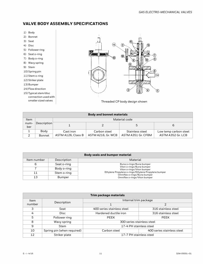
VALVE BODY ASSEMBLY SPECIFICATIONS
1) Body
2) Bonnet
3) Seat
4) Disc
5) Follower ring
6) Seat o-ring
7) Body o-ring
8) Wavy spring
9) Stem
10) Spring pin
11) Stem o-ring
12) Striker plate
13) Bumper
14) Flow direction
15) Typical stem/disc connection used with smaller sized valves Threaded CP body design shown
14
15
Body and bonnet materials
Item num-
berDescription
Material code
1 2 5 6
1 Body Cast ironASTM A126, Class B
Carbon steelASTM A216, Gr. WCB
Stainless steelASTM A351 Gr. CF8M
Low temp carbon steelASTM A352 Gr. LCB2 Bonnet
Body seals and bumper material
Item number Description Material6 Seat o-ring Buna o-rings/Buna bumper
Viton o-rings/Buna bumperViton o-rings/Viton bumper
Ethylene Propylene o-rings/Ethylene Propylene bumperOmniflex o-rings/Buna bumperOmniflex o-rings/Viton bumper
7 Body o-ring11 Stem o-ring13 Bumper
Trim package materials
Item number Description
Internal trim package1 2
3 Seat 400 series stainless steel 316 stainless steel4 Disc Hardened ductile iron 316 stainless steel5 Follower ring PEEK PEEK8 Wavy spring 300 series stainless steel9 Stem 17-4 PH stainless steel
10 Spring pin (when required) Carbon steel 400 series stainless steel12 Striker plate 17-7 PH stainless steel
E - i - 4/16 11 32M-05001—01
GAS ELECTRO-MECHANICAL VALVES
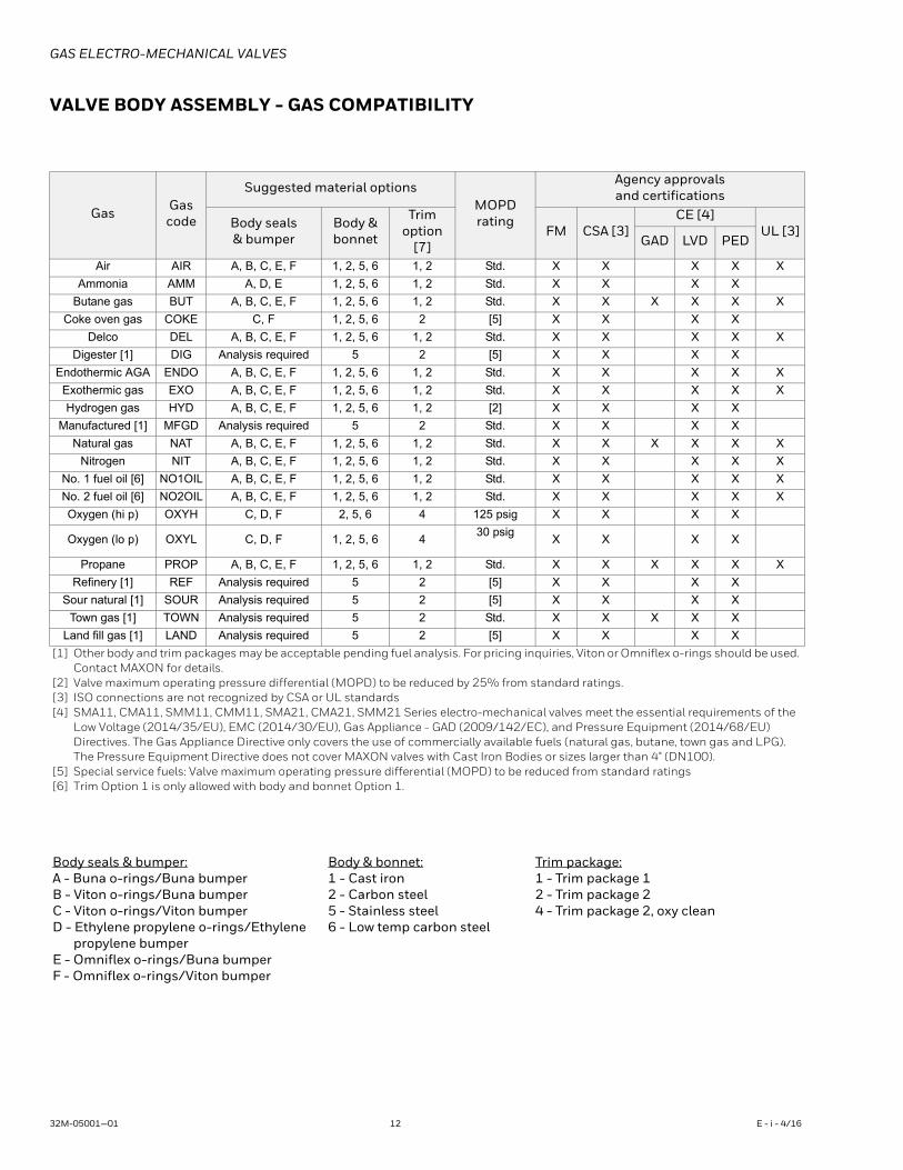
VALVE BODY ASSEMBLY - GAS COMPATIBILITY
Gas Gascode
Suggested material optionsMOPDrating
Agency approvals and certifications
Body seals & bumper
Body & bonnet
Trimoption
[7]FM CSA [3]
CE [4]UL [3]
GAD LVD PED
Air AIR A, B, C, E, F 1, 2, 5, 6 1, 2 Std. X X X X X
Ammonia AMM A, D, E 1, 2, 5, 6 1, 2 Std. X X X X
Butane gas BUT A, B, C, E, F 1, 2, 5, 6 1, 2 Std. X X X X X X
Coke oven gas COKE C, F 1, 2, 5, 6 2 [5] X X X X
Delco DEL A, B, C, E, F 1, 2, 5, 6 1, 2 Std. X X X X X
Digester [1] DIG Analysis required 5 2 [5] X X X X
Endothermic AGA ENDO A, B, C, E, F 1, 2, 5, 6 1, 2 Std. X X X X X
Exothermic gas EXO A, B, C, E, F 1, 2, 5, 6 1, 2 Std. X X X X X
Hydrogen gas HYD A, B, C, E, F 1, 2, 5, 6 1, 2 [2] X X X X
Manufactured [1] MFGD Analysis required 5 2 Std. X X X X
Natural gas NAT A, B, C, E, F 1, 2, 5, 6 1, 2 Std. X X X X X X
Nitrogen NIT A, B, C, E, F 1, 2, 5, 6 1, 2 Std. X X X X X
No. 1 fuel oil [6] NO1OIL A, B, C, E, F 1, 2, 5, 6 1, 2 Std. X X X X X
No. 2 fuel oil [6] NO2OIL A, B, C, E, F 1, 2, 5, 6 1, 2 Std. X X X X X
Oxygen (hi p) OXYH C, D, F 2, 5, 6 4 125 psig X X X X
Oxygen (lo p) OXYL C, D, F 1, 2, 5, 6 430 psig
X X X X
Propane PROP A, B, C, E, F 1, 2, 5, 6 1, 2 Std. X X X X X X
Refinery [1] REF Analysis required 5 2 [5] X X X X
Sour natural [1] SOUR Analysis required 5 2 [5] X X X X
Town gas [1] TOWN Analysis required 5 2 Std. X X X X X
Land fill gas [1] LAND Analysis required 5 2 [5] X X X X
[1] Other body and trim packages may be acceptable pending fuel analysis. For pricing inquiries, Viton or Omniflex o-rings should be used. Contact MAXON for details.
[2] Valve maximum operating pressure differential (MOPD) to be reduced by 25% from standard ratings.[3] ISO connections are not recognized by CSA or UL standards[4] SMA11, CMA11, SMM11, CMM11, SMA21, CMA21, SMM21 Series electro-mechanical valves meet the essential requirements of the
Low Voltage (2014/35/EU), EMC (2014/30/EU), Gas Appliance - GAD (2009/142/EC), and Pressure Equipment (2014/68/EU) Directives. The Gas Appliance Directive only covers the use of commercially available fuels (natural gas, butane, town gas and LPG). The Pressure Equipment Directive does not cover MAXON valves with Cast Iron Bodies or sizes larger than 4" (DN100).
[5] Special service fuels: Valve maximum operating pressure differential (MOPD) to be reduced from standard ratings[6] Trim Option 1 is only allowed with body and bonnet Option 1.
Body seals & bumper:A - Buna o-rings/Buna bumperB - Viton o-rings/Buna bumperC - Viton o-rings/Viton bumperD - Ethylene propylene o-rings/Ethylene
propylene bumperE - Omniflex o-rings/Buna bumperF - Omniflex o-rings/Viton bumper
Body & bonnet:1 - Cast iron2 - Carbon steel5 - Stainless steel6 - Low temp carbon steel
Trim package:1 - Trim package 12 - Trim package 24 - Trim package 2, oxy clean
32M-05001—01 12 E - i - 4/16
GAS ELECTRO-MECHANICAL VALVES
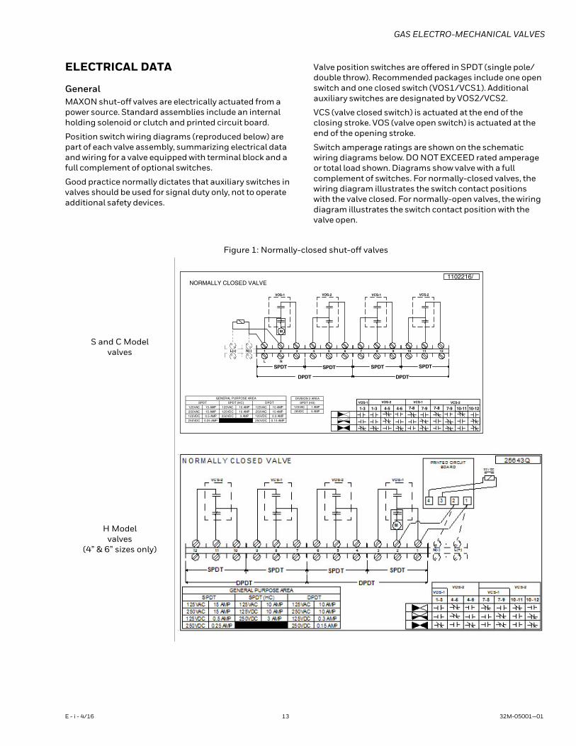
ELECTRICAL DATA
GeneralMAXON shut-off valves are electrically actuated from a power source. Standard assemblies include an internal holding solenoid or clutch and printed circuit board.
Position switch wiring diagrams (reproduced below) are part of each valve assembly, summarizing electrical data and wiring for a valve equipped with terminal block and a full complement of optional switches.
Good practice normally dictates that auxiliary switches in valves should be used for signal duty only, not to operate additional safety devices.
Valve position switches are offered in SPDT (single pole/double throw). Recommended packages include one open switch and one closed switch (VOS1/VCS1). Additional auxiliary switches are designated by VOS2/VCS2.
VCS (valve closed switch) is actuated at the end of the closing stroke. VOS (valve open switch) is actuated at the end of the opening stroke.
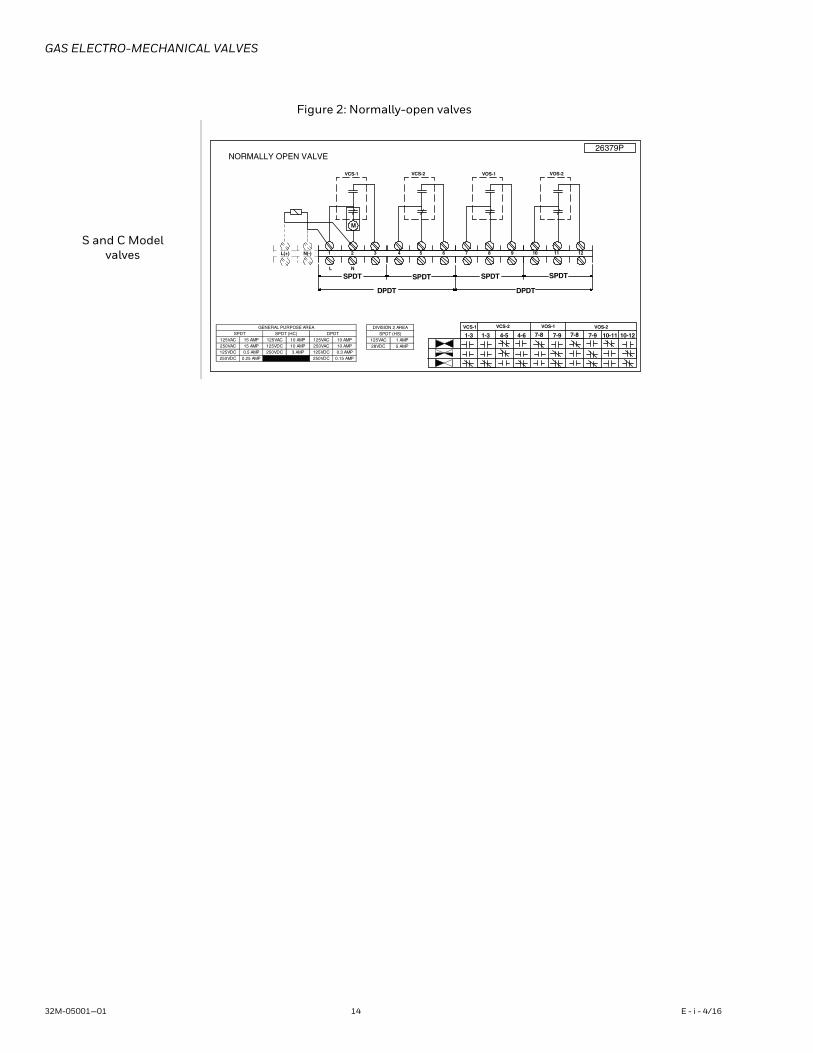
Switch amperage ratings are shown on the schematic wiring diagrams below. DO NOT EXCEED rated amperage or total load shown. Diagrams show valve with a full complement of switches. For normally-closed valves, the wiring diagram illustrates the switch contact positions with the valve closed. For normally-open valves, the wiring diagram illustrates the switch contact position with the valve open.
Figure 1: Normally-closed shut-off valves
S and C Modelvalves
H Modelvalves
(4” & 6” sizes only)
1-31-3 4-5 4-6 7-8 7-97-87-9 10-11 10-12VOS-1 VOS-2 VCS-1 VCS-2
1 2 3 4 5 6 7 8 9 10 11 12L(+) N(-)
M
VOS-1 VOS-2 VCS-1 VCS-2
SPDT SPDT
DPDTDPDT
SPDTSPDT L N
1102216/NORMALLY CLOSED VALVE
125VAC 1 AMP28VDC 5 AMP
SPDT (HS)DIVISION 2 AREA
125VAC 15 AMP 125VAC 10 AMP 125VAC 10 AMP250VAC 15 AMP 125VDC 10 AMP 250VAC 10 AMP125VDC 0.5 AMP 250VDC 3 AMP 125VDC 0.3 AMP
PMA 51.0CDV052PMA 52.0CDV052
SPDT (HC)SPDT DPDTGENERAL PURPOSE AREA
E - i - 4/16 13 32M-05001—01
GAS ELECTRO-MECHANICAL VALVES
Figure 2: Normally-open valves
S and C Modelvalves
NORMALLY OPEN VALVE
1-31-3 4-5 4-6 7-8 7-97-87-9 10-11 10-12VCS-1 VCS-2 VOS-1 VOS-2
1 2 3 4 5 6 7 8 9 10 11 12L(+) N(-)
M
VCS-1 VCS-2 VOS-1 VOS-2
SPDT SPDT
DPDTDPDT
SPDTSPDTL N
26379P
125VAC 15 AMP 125VAC 10 AMP 125VAC 10 AMP250VAC 15 AMP 125VDC 10 AMP 250VAC 10 AMP125VDC 0.5 AMP 250VDC 3 AMP 125VDC 0.3 AMP
PMA 51.0CDV052PMA 52.0CDV052
SPDT (HC)SPDT DPDTGENERAL PURPOSE AREA
125VAC 1 AMP28VDC 5 AMP
SPDT (HS)DIVISION 2 AREA
32M-05001—01 14 E - i - 4/16
GAS ELECTRO-MECHANICAL VALVES
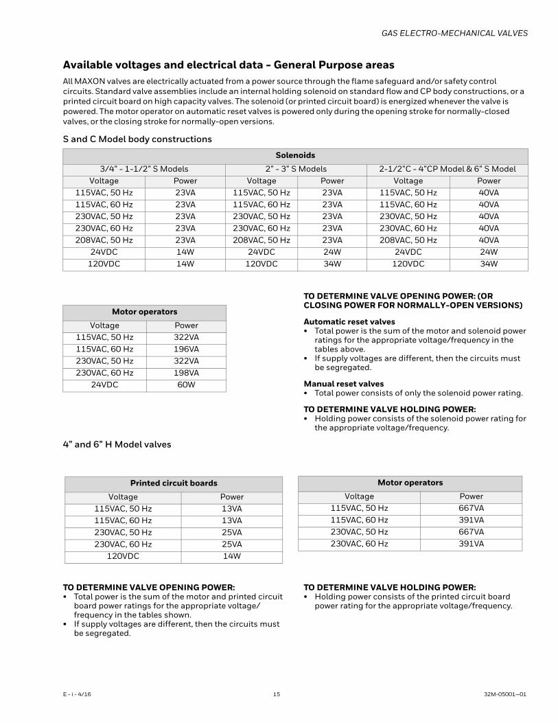
Available voltages and electrical data - General Purpose areasAll MAXON valves are electrically actuated from a power source through the flame safeguard and/or safety control circuits. Standard valve assemblies include an internal holding solenoid on standard flow and CP body constructions, or a printed circuit board on high capacity valves. The solenoid (or printed circuit board) is energized whenever the valve is powered. The motor operator on automatic reset valves is powered only during the opening stroke for normally-closed valves, or the closing stroke for normally-open versions.
S and C Model body constructions
TO DETERMINE VALVE OPENING POWER: (OR CLOSING POWER FOR NORMALLY-OPEN VERSIONS)
Automatic reset valves• Total power is the sum of the motor and solenoid power
ratings for the appropriate voltage/frequency in the tables above.
• If supply voltages are different, then the circuits must be segregated.
Manual reset valves• Total power consists of only the solenoid power rating.
TO DETERMINE VALVE HOLDING POWER:• Holding power consists of the solenoid power rating for
the appropriate voltage/frequency.
4” and 6” H Model valves
TO DETERMINE VALVE OPENING POWER:• Total power is the sum of the motor and printed circuit
board power ratings for the appropriate voltage/frequency in the tables shown.
• If supply voltages are different, then the circuits must be segregated.
TO DETERMINE VALVE HOLDING POWER:• Holding power consists of the printed circuit board
power rating for the appropriate voltage/frequency.
Solenoids
3/4” - 1-1/2” S Models 2” - 3” S Models 2-1/2”C - 4”CP Model & 6” S ModelVoltage Power Voltage Power Voltage Power
115VAC, 50 Hz 23VA 115VAC, 50 Hz 23VA 115VAC, 50 Hz 40VA115VAC, 60 Hz 23VA 115VAC, 60 Hz 23VA 115VAC, 60 Hz 40VA230VAC, 50 Hz 23VA 230VAC, 50 Hz 23VA 230VAC, 50 Hz 40VA230VAC, 60 Hz 23VA 230VAC, 60 Hz 23VA 230VAC, 60 Hz 40VA208VAC, 50 Hz 23VA 208VAC, 50 Hz 23VA 208VAC, 50 Hz 40VA
24VDC 14W 24VDC 24W 24VDC 24W120VDC 14W 120VDC 34W 120VDC 34W
Motor operators
Voltage Power115VAC, 50 Hz 322VA115VAC, 60 Hz 196VA230VAC, 50 Hz 322VA230VAC, 60 Hz 198VA
24VDC 60W
Printed circuit boards
Voltage Power115VAC, 50 Hz 13VA115VAC, 60 Hz 13VA230VAC, 50 Hz 25VA230VAC, 60 Hz 25VA
120VDC 14W
Motor operators
Voltage Power115VAC, 50 Hz 667VA115VAC, 60 Hz 391VA230VAC, 50 Hz 667VA230VAC, 60 Hz 391VA
E - i - 4/16 15 32M-05001—01
GAS ELECTRO-MECHANICAL VALVES
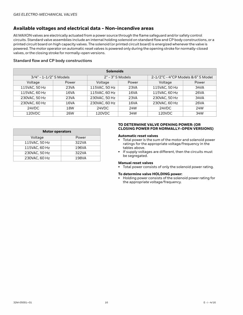
Available voltages and electrical data - Non-incendive areasAll MAXON valves are electrically actuated from a power source through the flame safeguard and/or safety control circuits. Standard valve assemblies include an internal holding solenoid on standard flow and CP body constructions, or a printed circuit board on high capacity valves. The solenoid (or printed circuit board) is energized whenever the valve is powered. The motor operator on automatic reset valves is powered only during the opening stroke for normally-closed valves, or the closing stroke for normally-open versions.
Standard flow and CP body constructions
TO DETERMINE VALVE OPENING POWER: (OR CLOSING POWER FOR NORMALLY-OPEN VERSIONS)
Automatic reset valves• Total power is the sum of the motor and solenoid power
ratings for the appropriate voltage/frequency in the tables above.
• If supply voltages are different, then the circuits must be segregated.
Manual reset valves• Total power consists of only the solenoid power rating.
To determine valve HOLDING power:• Holding power consists of the solenoid power rating for
the appropriate voltage/frequency.
Solenoids
3/4” - 1-1/2” S Models 2” - 3” S Models 2-1/2”C - 4”CP Models & 6” S ModelVoltage Power Voltage Power Voltage Power
115VAC, 50 Hz 23VA 115VAC, 50 Hz 23VA 115VAC, 50 Hz 34VA115VAC, 60 Hz 16VA 115VAC, 60 Hz 16VA 115VAC, 60 Hz 26VA230VAC, 50 Hz 23VA 230VAC, 50 Hz 23VA 230VAC, 50 Hz 34VA230VAC, 60 Hz 16VA 230VAC, 60 Hz 16VA 230VAC, 60 Hz 26VA
24VDC 18W 24VDC 24W 24VDC 24W120VDC 26W 120VDC 34W 120VDC 34W
Motor operators
Voltage Power115VAC, 50 Hz 322VA115VAC, 60 Hz 196VA230VAC, 50 Hz 322VA230VAC, 60 Hz 198VA
32M-05001—01 16 E - i - 4/16
GAS ELECTRO-MECHANICAL VALVES
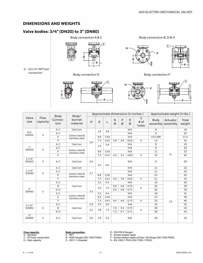
DIMENSIONS AND WEIGHTS
Valve bodies: 3/4” (DN20) to 3” (DN80)
1) (2) 1/4” NPT test connection
Body connection A & C Body connection B, D & H
Body connection E Body connection F
Valvesize
Flowcapacity
BodyConnec-
tion
Body/bonnet
material
Approximate dimensions (in inches ) Approximate weight (in lbs )
H K L NØ
PØ
RØ
S# of
holes
Bodyassembly
Actuatorassembly
Totalweight
3/4”(DN20) S
A, C Cast iron
2.0
1.9 3.8 N/A 8
11
19
A, CCarbon steel & stainless steel
N/A 9 20
E 6.9 13.8 N/A 10.5 266 21.5
F 7.3 14.5 3.9 2.8 0.62 4 13 24
1”(DN25) S
A, C Cast iron1.9 3.8 N/A 8 19
A, CCarbon steel & stainless steel
N/A 9 20
E 6.9 13.8 N/A 11 22
F 7.3 14.5 4.3 3.1 0.62 4 15 26
1-1/4”(DN32) S A, C Cast iron 2.4
2.0 4.0
N/A 9 20
1-1/2”(DN40) S
A, C Cast iron
2.7
N/A 11 22
A, CCarbon steel & stainless steel
N/A 11 22
E 6.8 13.6 N/A 14 25
F 7.2 14.4 5.0 3.9 0.62 4 21 32
2”(DN50) S
A, C
Cast iron
3.3
2.2 4.4 N/A 16
13
29
B3.5 7.0
6.0 4.8 0.75 4
26 39
D, H 6.5 4.9 0.71 26 39
A, CCarbon steel & stainless steel
2.2 4.4 N/A 18 31
E 6.9 13.8 N/A 23 36
F 7.3 14.5 6.0 4.8 0.75 4 33 46
2-1/2”(DN65) S
A, C
Cast iron
2.9 2.5 5.0 N/A 19 32
B3.1 3.8 7.5
7.0 5.5 0.75 4
30 43
D, H 7.3 5.7 0.71 30 43
3”(DN80) S A, C Cast iron 3.0 2.6 5.2 N/A 20 33
Flow capacity:S - StandardC - CP body constructionH - High capacity
Body connection:A - NPTB - ANSI flanged (ISO 7005 PN20)C - ISO 7-1 threaded
D - DIN PN16 flangedE - Socket welded nippleF - Socket welded nipple w/Class 150 flange (ISO 7005 PN20)H - EN 1092-1 PN16 (ISO 7005-1 PN16)
L K
H
1
R S
N
H
K L
P
1
L K
H
1
R S L
N
K
H
P
1
E - i - 4/16 17 32M-05001—01
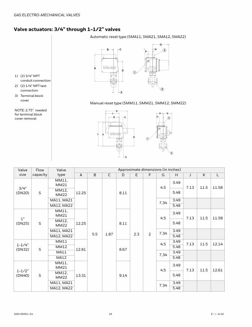
GAS ELECTRO-MECHANICAL VALVES
Valve actuators: 3/4” through 1-1/2” valves
1) (2) 3/4” NPT conduit connection
2) (2) 1/4” NPT test connection
3) Terminal block cover
NOTE: 2.75” needed for terminal block cover removal
Automatic reset type (SMA11, SMA21, SMA12, SMA22)
Manual reset type (SMM11, SMM21, SMM12, SMM22)
Valvesize
Flowcapacity
Valvetype
Approximate dimensions (in inches)A B C D E F G H J K L
3/4”(DN20) S
MM11, MM21
12.25
5.5 1.87
8.11
2.3 2
4.5 3.49
7.13 11.5 11.58 MM12, MM22 5.48
MA11, MA217.34
3.49 MA12, MA22 5.48
1”(DN25) S
MM11, MM21
12.25 8.11 4.5
3.49 7.13 11.5 11.58
MM12, MM22 5.48
MA11, MA217.34
3.49 MA12, MA22 5.48
1-1/4”(DN32) S
MM11
12.81 8.67 4.5
3.49 7.13 11.5 12.14
MM12 5.48 MA11
7.34 3.49
MA12 5.48
1-1/2”(DN40) S
MM11, MM21
13.31 9.14 4.5
3.49 7.13 11.5 12.61
MM12, MM22 5.48
MA11, MA217.34
3.49 MA12, MA22 5.48
C
E
AD
F
G
HB
1
2
3
KJ
B C
D
E
L A
H G
F
1
2
3
32M-05001—01 18 E - i - 4/16
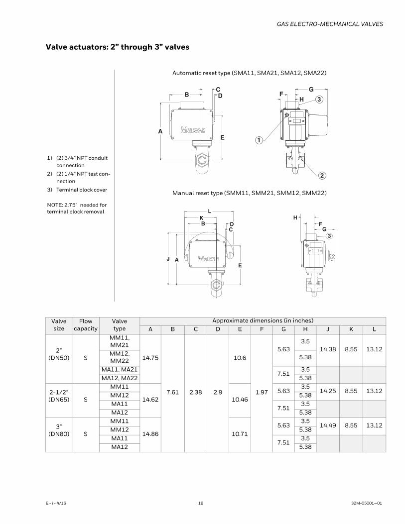
GAS ELECTRO-MECHANICAL VALVES
Valve actuators: 2” through 3” valves
1) (2) 3/4” NPT conduit connection
2) (2) 1/4” NPT test con-nection
3) Terminal block cover
NOTE: 2.75” needed for terminal block removal
Automatic reset type (SMA11, SMA21, SMA12, SMA22)
Manual reset type (SMM11, SMM21, SMM12, SMM22)
CDB
AE
G
HF
1
2
3
LKB D
C
EJ A
FG
H
3
Valvesize
Flowcapacity
Valvetype
Approximate dimensions (in inches)A B C D E F G H J K L
2”(DN50) S
MM11, MM21
14.75
7.61 2.38 2.9
10.6
1.97
5.63 3.5
14.38 8.55 13.12 MM12, MM22 5.38
MA11, MA217.51
3.5 MA12, MA22 5.38
2-1/2”(DN65) S
MM11
14.62 10.46 5.63
3.5 14.25 8.55 13.12
MM12 5.38 MA11
7.51 3.5
MA12 5.38
3”(DN80) S
MM11
14.86 10.71 5.63
3.5 14.49 8.55 13.12
MM12 5.38 MA11
7.51 3.5
MA12 5.38
E - i - 4/16 19 32M-05001—01
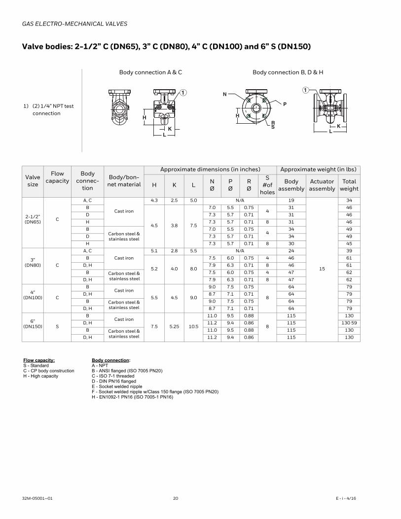
GAS ELECTRO-MECHANICAL VALVES
Valve bodies: 2-1/2” C (DN65), 3” C (DN80), 4” C (DN100) and 6” S (DN150)
1) (2) 1/4” NPT test connection
Body connection A & C Body connection B, D & H
Valvesize
Flowcapacity
Body connec-
tion
Body/bon-net material
Approximate dimensions (in inches) Approximate weight (in lbs)
H K L NØ
PØ
RØ
S#of
holes
Bodyassembly
Actuatorassembly
Totalweight
2-1/2”(DN65) C
A, C
Cast iron
4.3 2.5 5.0 N/A 19
15
34
B
4.5 3.8 7.5
7.0 5.5 0.75 4
31 46
D 7.3 5.7 0.71 31 46
H 7.3 5.7 0.71 8 31 46
BCarbon steel & stainless steel
7.0 5.5 0.75 4
34 49
D 7.3 5.7 0.71 34 49
H 7.3 5.7 0.71 8 30 45
3”(DN80) C
A, C
Cast iron
5.1 2.8 5.5 N/A 24 39
B
5.2 4.0 8.0
7.5 6.0 0.75 4 46 61
D, H 7.9 6.3 0.71 8 46 61
B Carbon steel & stainless steel
7.5 6.0 0.75 4 47 62
D, H 7.9 6.3 0.71 8 47 62
4”(DN100) C
BCast iron
5.5 4.5 9.0
9.0 7.5 0.75
8
64 79
D, H 8.7 7.1 0.71 64 79
B Carbon steel & stainless steel
9.0 7.5 0.75 64 79
D, H 8.7 7.1 0.71 64 79
6”(DN150) S
BCast iron
7.5 5.25 10.5
11.0 9.5 0.88
8
115 130
D, H 11.2 9.4 0.86 115 130 59
B Carbon steel & stainless steel
11.0 9.5 0.88 115 130
D, H 11.2 9.4 0.86 115 130
Flow capacity:S - StandardC - CP body constructionH - High capacity
Body connection:A - NPTB - ANSI flanged (ISO 7005 PN20)C - ISO 7-1 threadedD - DIN PN16 flangedE - Socket welded nippleF - Socket welded nipple w/Class 150 flange (ISO 7005 PN20)H - EN1092-1 PN16 (ISO 7005-1 PN16)
L K
H
1
R S
N
H
K L
P
1
32M-05001—01 20 E - i - 4/16
GAS ELECTRO-MECHANICAL VALVES
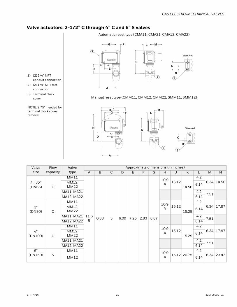
Valve actuators: 2-1/2” C through 4” C and 6” S valves
1) (2) 3/4” NPT conduit connection
2) (2) 1/4” NPT test connection
3) Terminal block cover
NOTE: 2.75” needed for terminal block cover removal
Automatic reset type (CMA11, CMA21, CMA12, CMA22)
Manual reset type (CMM11, CMM12, CMM22, SMM11, SMM12)
Valvesize
Flowcapacity
Valvetype
Approximate dimensions (in inches)A B C D E F G H J K L M N
2-1/2”(DN65) C
MM11
11.68 0.88 3 6.09 7.25 2.83 8.87
10.94 15.12
14.56
4.2 6.34 14.56 MM12,
MM22 6.14
MA11, MA21 4.2 7.51
MA12, MA22 6.14
3”(DN80) C
MM1110.9
4 15.12 15.29
4.2 6.34 17.97 MM12,
MM22 6.14
MA11, MA21 4.2 7.51
MA12, MA22 6.14
4”(DN100) C
MM1110.9
4 15.12 15.29
4.2 6.34 17.97 MM12,
MM22 6.14
MA11, MA21 4.2 7.51
MA12, MA22 6.14 6”
(DN150) SMM11 10.9
4 15.12 20.75 4.2
6.34 23.43 MM12 6.14
G F
DC
B
A
E
View A-A
AA
ML
K
12
3
A
JH
G F
N
D C
B
AE
A
A
View A-A
ML
K
12
E - i - 4/16 21 32M-05001—01
GAS ELECTRO-MECHANICAL VALVES
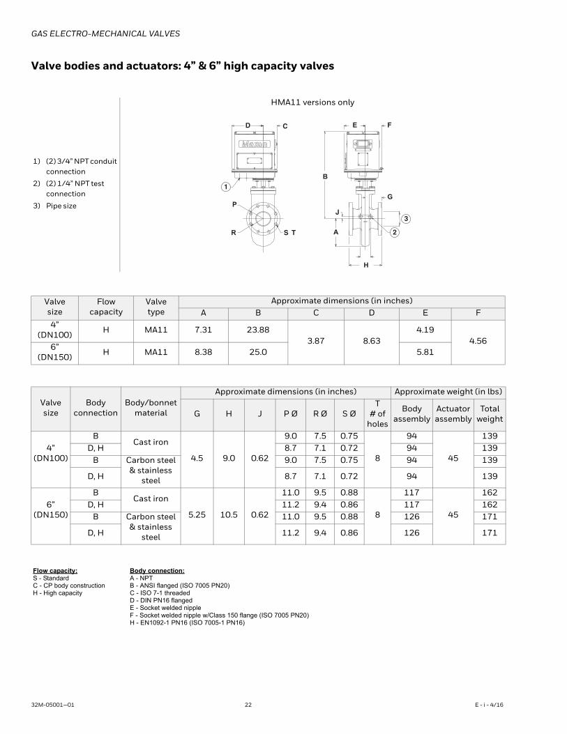
Valve bodies and actuators: 4” & 6” high capacity valves
1) (2) 3/4” NPT conduit connection
2) (2) 1/4” NPT test connection
3) Pipe size
HMA11 versions only
Valvesize
Flowcapacity
Valvetype
Approximate dimensions (in inches)A B C D E F
4”(DN100) H MA11 7.31 23.88
3.87 8.63 4.19
4.56 6”
(DN150) H MA11 8.38 25.0 5.81
Valvesize
Body connection
Body/bonnetmaterial
Approximate dimensions (in inches) Approximate weight (in lbs)
G H J P Ø R Ø S ØT
# of holes
Bodyassembly
Actuatorassembly
Totalweight
4”(DN100)
BCast iron
4.5 9.0 0.62
9.0 7.5 0.75
8
94
45
139 D, H 8.7 7.1 0.72 94 139
B Carbon steel & stainless
steel
9.0 7.5 0.75 94 139
D, H 8.7 7.1 0.72 94 139
6”(DN150)
BCast iron
5.25 10.5 0.62
11.0 9.5 0.88
8
117
45
162 D, H 11.2 9.4 0.86 117 162
B Carbon steel & stainless
steel
11.0 9.5 0.88 126 171
D, H 11.2 9.4 0.86 126 171
Flow capacity:S - StandardC - CP body constructionH - High capacity
Body connection:A - NPTB - ANSI flanged (ISO 7005 PN20)C - ISO 7-1 threadedD - DIN PN16 flangedE - Socket welded nippleF - Socket welded nipple w/Class 150 flange (ISO 7005 PN20)H - EN1092-1 PN16 (ISO 7005-1 PN16)
D C
P
R
E F
G
S T
H
A
B
J
1
2
3
32M-05001—01 22 E - i - 4/16
GAS ELECTRO-MECHANICAL VALVES
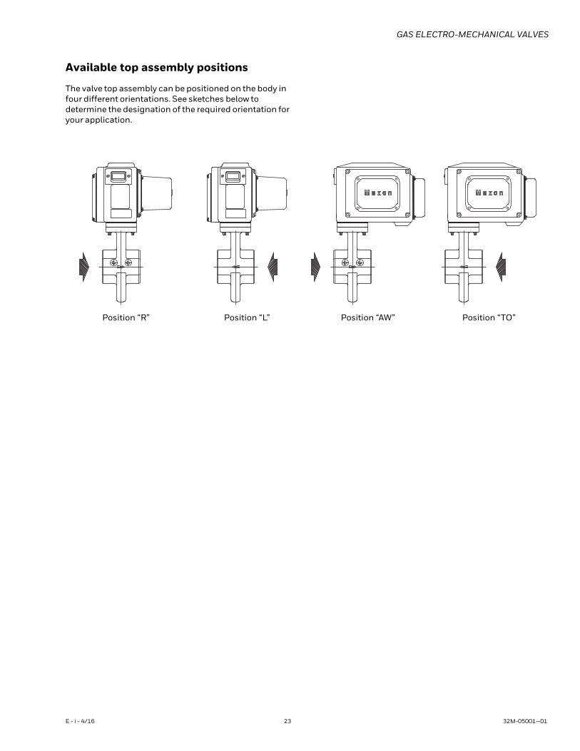
Available top assembly positions
The valve top assembly can be positioned on the body in four different orientations. See sketches below to determine the designation of the required orientation for your application.
Position “R” Position “L” Position “AW” Position “TO”
E - i - 4/16 23 32M-05001—01
GAS ELECTRO-MECHANICAL VALVES
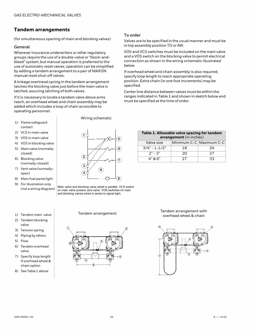
Tandem arrangements
(for simultaneous opening of main and blocking valves)
GeneralWherever insurance underwriters or other regulatory groups require the use of a double-valve or “block-and-bleed” system, but manual operation is preferred to the use of automatic reset valves, operation can be simplified by adding a tandem arrangement to a pair of MAXON manual reset shut-off valves.
A linkage overtravel spring in the tandem arrangement latches the blocking valve just before the main valve is latched, assuring latching of both valves.
If it is necessary to locate a tandem valve above arms reach, an overhead wheel and chain assembly may be added which includes a loop of chain accessible to operating personnel.
To orderValves are to be specified in the usual manner and must be in top assembly position TO or AW.
VOS and VCS switches must be included on the main valve and a VOS switch on the blocking valve to permit electrical connection as shown in the wiring schematic illustrated below.
If overhead wheel and chain assembly is also required, specify loop length to reach appropriate operating position. Extra chain (in one foot increments) may be specified.
Center line distance between valves must be within the ranges indicated in Table 1 and shown in sketch below and must be specified at the time of order.
1) Flame safeguard contact
2) VCS in main valve
3) VOS in main valve
4) VOS in blocking valve
5) Main valve (normally-closed)
6) Blocking valve (normally-closed)
7) Vent valve (normally-open)
8) Main fuel panel light
9) For illustration only (not a wiring diagram)
Wiring schematic
Main valve and blocking valve wired in parallel. VCS switch on main valve powers vent valve. VOS switches on main and blocking valves wired in series to signal light.
1
2
3
49
5
6
7
8
Table 1. Allowable valve spacing for tandem arrangement (in inches)
Valve size Minimum C-C Maximum C-C3/4” - 1-1/2” 18 24
2” - 3” 20 27 4” & 6” 27 33
1) Tandem main valve
2) Tandem blocking valve
3) Tension spring
4) Piping by others
5) Flow
6) Tandem overhead valve
7) Specify loop length if overhead wheel & chain option
8) See Table 1 above
Tandem arrangement Tandem arrangement with overhead wheel & chain
2
5
8
4
3
1
7
5
3
4
26
32M-05001—01 24 E - i - 4/16
GAS ELECTRO-MECHANICAL VALVES
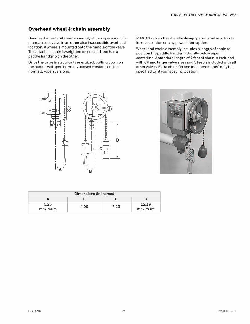
Overhead wheel & chain assembly
Overhead wheel and chain assembly allows operation of a manual reset valve in an otherwise inaccessible overhead location. A wheel is mounted onto the handle of the valve. The attached chain is weighted on one end and has a paddle handgrip on the other.
Once the valve is electrically energized, pulling down on the paddle will open normally-closed versions or close normally-open versions.
MAXON valve’s free-handle design permits valve to trip to its rest position on any power interruption.
Wheel and chain assembly includes a length of chain to position the paddle handgrip slightly below pipe centerline. A standard length of 7 feet of chain is included with CP and larger valve sizes and 5 feet is included with all other valves. Extra chain (in one foot increments) may be specified to fit your specific location.
B
C
D
A
Dimensions (in inches)A B C D
5.25 maximum 4.06 7.25 12.19
maximum
E - i - 4/16 25 32M-05001—01
GAS ELECTRO-MECHANICAL VALVES
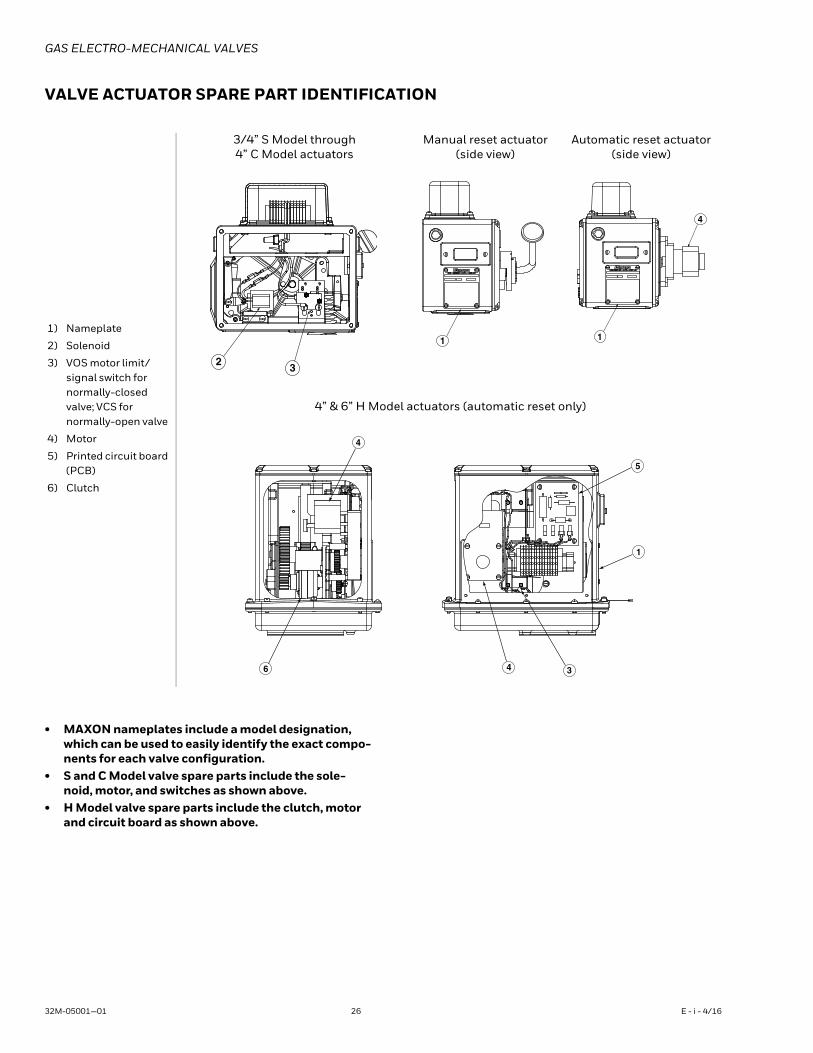
VALVE ACTUATOR SPARE PART IDENTIFICATION
• MAXON nameplates include a model designation, which can be used to easily identify the exact compo-nents for each valve configuration.
• S and C Model valve spare parts include the sole-noid, motor, and switches as shown above.
• H Model valve spare parts include the clutch, motor and circuit board as shown above.
1) Nameplate
2) Solenoid
3) VOS motor limit/signal switch for normally-closed valve; VCS for normally-open valve
4) Motor
5) Printed circuit board (PCB)
6) Clutch
3/4” S Model through 4” C Model actuators
Manual reset actuator(side view)
Automatic reset actuator(side view)
4” & 6” H Model actuators (automatic reset only)
23
1 1
4
6
4
4 3
1
5
32M-05001—01 26 E - i - 4/16
GAS ELECTRO-MECHANICAL VALVES
MANUFACTURER AND IMPORTER ADDRESSESBelow are the addresses and contact information for the Honeywell – Maxon manufacturing location and European sales office. The Eu-ropean sales office serves as the importer and EU manufacturer's representative under the EU New Legislative Framework (NLF).
MUNCIE, INDIANA, USA – MANUFACTURER201 East 18th StreetP.O. Box 2068Muncie, IN 47307-0068
Tel: 765.284.3304
Fax: 765.286.8394
EUROPEAN SALES OFFICE – IMPORTERBELGIUMMaxon International BVBALuchthavenlaan 16-181800 Vilvoorde, Belgium
Tel: 32.2.255.09.09
Fax: 32.2.251.82.41
Please read the operating and mounting instructions before using the equipment. Install the equipment in compliance with the prevailing regulations.
Bedrijfs- en montagehandleiding voor gebruik goed lezen! Apparaat moet volgens de geldende voorschriften worden geïnstalleerd.
Lire les instructions de montage et de service avant utilisation! L’appareil doit imperativement être installé selon les règlementations en vigueur.
Betriebs- und Montageanleitung vor Gebrauch lesen! Gerät muß nach den geltenden Vorschriften installiert werden.
E - i - 4/16 27 32M-05001—01
GAS ELECTRO-MECHANICAL VALVES
WARNINGThe installation, operation and maintenance instructions contain important information that must be read and followed by anyone operating or servicing this product. Do not operate or service this equipment unless the instructions have been read. IMPROPER INSTALLATION OR USE OF THIS PRODUCT COULD RESULT IN BODILY INJURY OR DEATH.
DescriptionMAXON electro-mechanical valves are electrically actuated fuel shut-off valves. The valves are designed for a fast acting return to the at rest position upon removal of a control voltage signal. Motorized automatic and manual actuators are available depending on application needs. In addition, normally-closed and normally-open options are available. The normally-closed versions will shut off flow when de-energized and pass flow when energized. The normally-open versions will shut off flow when energized and pass flow when de-energized. Electro-mechanical valves are also offered in configurations that meet hazardous locations.
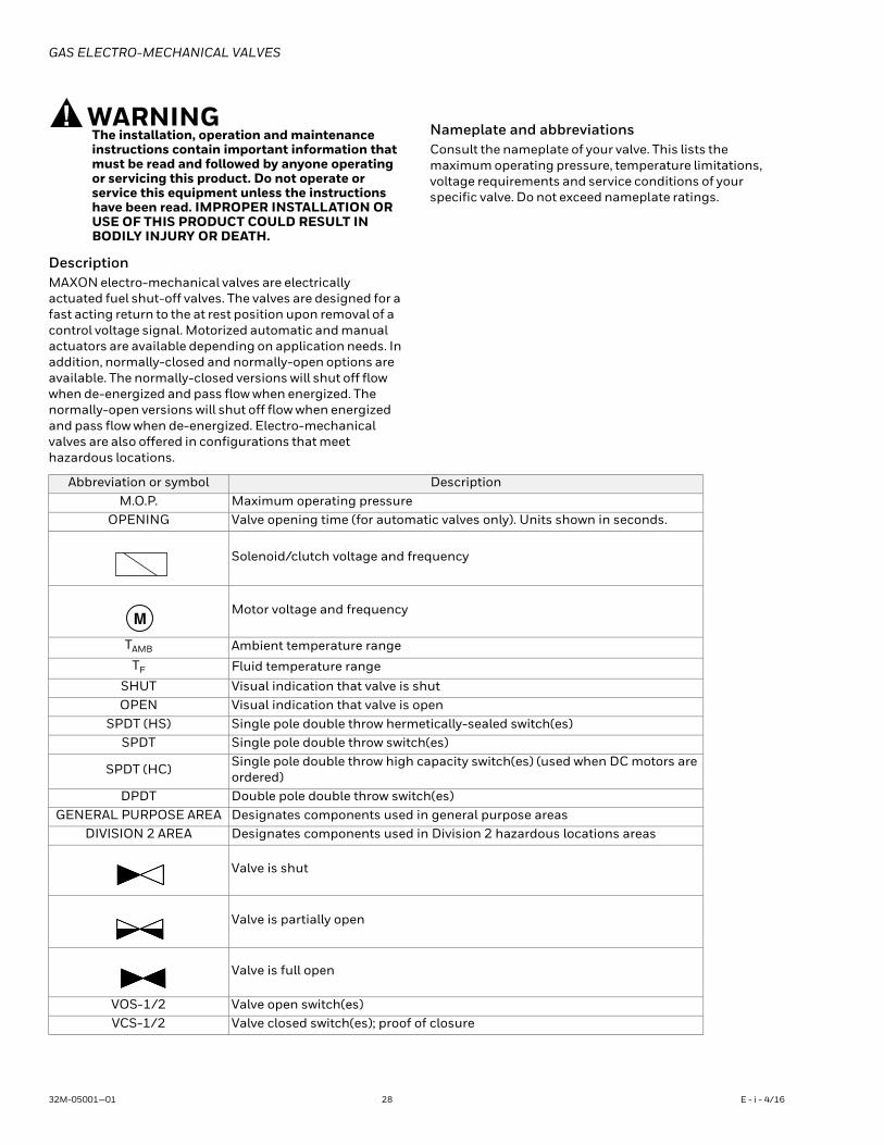
Nameplate and abbreviationsConsult the nameplate of your valve. This lists the maximum operating pressure, temperature limitations, voltage requirements and service conditions of your specific valve. Do not exceed nameplate ratings.
Abbreviation or symbol DescriptionM.O.P. Maximum operating pressure
OPENING Valve opening time (for automatic valves only). Units shown in seconds.
Solenoid/clutch voltage and frequency
Motor voltage and frequency
TAMB Ambient temperature rangeTF Fluid temperature range
SHUT Visual indication that valve is shutOPEN Visual indication that valve is open
SPDT (HS) Single pole double throw hermetically-sealed switch(es)SPDT Single pole double throw switch(es)
SPDT (HC) Single pole double throw high capacity switch(es) (used when DC motors are ordered)
DPDT Double pole double throw switch(es)GENERAL PURPOSE AREA Designates components used in general purpose areas
DIVISION 2 AREA Designates components used in Division 2 hazardous locations areas
Valve is shut
Valve is partially open
Valve is full open
VOS-1/2 Valve open switch(es)VCS-1/2 Valve closed switch(es); proof of closure
M
32M-05001—01 28 E - i - 4/16
GAS ELECTRO-MECHANICAL VALVES
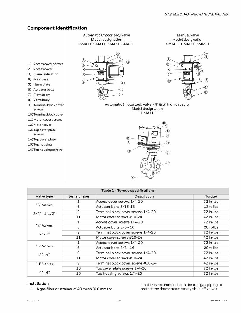
Component identification
Installation1. A gas filter or strainer of 40 mesh (0.6 mm) or
smaller is recommended in the fuel gas piping to protect the downstream safety shut-off valves.
1) Access cover screws
2) Access cover
3) Visual indication
4) Mainbase
5) Nameplate
6) Actuator bolts
7) Flow arrow
8) Valve body
9) Terminal block cover screws
10) Terminal block cover
11) Motor cover screws
12) Motor cover
13) Top cover plate screws
14) Top cover plate
15) Top housing
16) Top housing screws
Automatic (motorized) valveModel designation
SMA11, CMA11, SMA21, CMA21
Manual valveModel designation
SMM11, CMM11, SMM21
Automatic (motorized) valve - 4” & 6” high capacityModel designation
HMA11
Table 1 - Torque specifications
Valve type Item number Description Torque
“S” Valves
3/4” - 1-1/2”
1 Access cover screws 1/4-20 72 in-lbs 6 Actuator bolts 5/16-18 13 ft-lbs 9 Terminal block cover screws 1/4-20 72 in-lbs
11 Motor cover screws #10-24 42 in-lbs
“S” Valves
2” - 3”
1 Access cover screws 1/4-20 72 in-lbs 6 Actuator bolts 3/8 - 16 20 ft-lbs 9 Terminal block cover screws 1/4-20 72 in-lbs
11 Motor cover screws #10-24 42 in-lbs
“C” Valves
2” - 4”
1 Access cover screws 1/4-20 72 in-lbs 6 Actuator bolts 3/8 - 16 20 ft-lbs 9 Terminal block cover screws 1/4-20 72 in-lbs
11 Motor cover screws #10-24 42 in-lbs
“H” Valves
4” - 6”
9 Terminal block cover screws #10-24 42 in-lbs 13 Top cover plate screws 1/4-20 72 in-lbs 16 Top housing screws 1/4-20 72 in-lbs
10
11 12
9
6
8
7
1
2
3
4
5
10
9
6
8
7
1
2
3
4
5
10
9
5
7
3
1314
15
16
6
8
E - i - 4/16 29 32M-05001—01
GAS ELECTRO-MECHANICAL VALVES
2. Properly support and pipe the valve in the direction of the flow arrow on the valve body. Valve seats are direc-tional. Sealing will be maintained at full rated pres-sures in one direction only. Sealing will be provided in reverse flow only at reduced pressures.
3. Mount valve so that open/shut window indicator will be visible to your operating personnel. The open/shut window indicator should never face downward. The valve side plates should be located in a vertical plane for best performance. Valves are usually installed in horizontal piping; however, other orientations are acceptable, subject to the above limitations. The top assemblies of all MAXON valves are field rotatable to allow installations involving conflicts with these mounting restrictions.
4. Wire the valve in accordance with all applicable local and national codes and standards. In U.S. and Can-ada, wiring must conform to the NEC ANSI/NFPA 70 and/or CSA C22.1, Part 1.• Supply voltages must agree with valve’s
nameplate voltage within -15%/+10% for proper operation. For electrical wiring schematic, see instructions or sample affixed inside valve terminal block cover.
• Grounding is achieved with a grounding screw, which is located in the top assembly.
• Customer connections are provided via terminal blocks located in the top assembly.
• Main power wiring (120 VAC or 240 VAC) must be segregated from lower voltage 24 VDC signal wiring, when both are required.
• To eliminate any potential for gas to enter the electrical wiring system, install a conduit seal fitting at the actuator conduit hub.
5. Maintain integrity of the electro-mechanical actuator enclosures by using the appropriate electrical connec-tors for the (2) 3/4” NPT conduit threaded connec-tions. The electrical enclosure is NEMA 4 rated with an option for NEMA 4X.
6. All access cover plate screws should be tightened using an alternate cross-corner tightening pattern to the values shown in Table 1 on page 24.
7. Verify proper installation and operation by electrically actuating the valve for 10-15 cycles prior to the first introduction of gas.
8. WARNING - Explosion hazard• Do not connect or disconnect this equipment
unless power has been removed or the area is known to be non-hazardous.
• Substitution of components may impair suitability for Class I, Division 2 (applies to MM12, MA12, MM22 and MA22 valves only).
9. This equipment is suitable for installation in Class I, Division 2 Groups B, C, D, and Class II Groups F and G, and Class III hazardous locations or non-hazardous locations (applies to MM12, MA12, MM22 and MA22 valves only).
Auxiliary features• Non-adjustable proof of closure switch(es) with
valve seal over travel interlock• Auxiliary switch for indication of full travel (open for
normally-closed valves, closed for normally-open valves)
Operating environment• Actuators rated for NEMA 4 or optional NEMA 4X• Ambient and fluid temperature range of -20°F to
+140°F for S and C Model constructions• Ambient and fluid temperature range of -20°F to
+125°F for H Model constructions• All valves for oxygen service or using Ethylene Pro-
pylene body seals are limited to a minimum ambient and fluid temperature of 0°F
32M-05001—01 30 E - i - 4/16
GAS ELECTRO-MECHANICAL VALVES
ACTUATOR ASSEMBLY ROTATION
WARNINGMAXON electro-mechanical valves should be ordered in a configuration compatible with planned piping. If valve orientation is not correct, the actuator assembly can be rotated in 90° increments around the valve body centerline axis using the procedure below.
1. Shut off all electrical power and close off upstream manual cock.
2. Remove terminal block cover plate and disconnect power lead wires. (Tag carefully for later re-assembly.)
3. Remove conduit and electrical leads.4. Note physical position of any signal switch actuator
wands on auxiliary signal switches.5. Unscrew the two actuator bolts screwed up from the
bottom to 1/4 inch. DO NOT completely remove. These bolts secure the valve body to the valve’s top assembly housing.
6. Gently lift the top assembly (not more than 1/4” in height); just enough to break the seal between the valve body assembly and the rubber gasket adhering to the bottom of the top housing.
WARNING Lifting too far may dislodge some small parts inside the top housing, requiring complex re-assembly and retesting by trained factory personnel.
7. Remove the two actuator bolts screwed up from the bottom (were partially unscrewed in step 5).
8. Carefully rotate top assembly to the desired position in a plane parallel to the top of the valve body casting. Rotate the top housing about 30° beyond this posi-tion, and then rotate it back. Reposition the top hous-ing back down onto the valve body casting. This should align the open/shut indicator with its window and provide proper alignment of the internal mecha-nism.
9. Realign holes in valve body casting with the corre-sponding tapped holes in the bottom of the top assembly housing. Be sure the gasket is still in place between the body and top housing.
10. Reinsert the actuator bolts up from the bottom through the body and carefully engage threads of the top assembly. Tighten securely.
11. Reconnect conduit and electrical leads, then check that signal switch wands are properly positioned and that the open/shut indicator moves freely. Failure to correct any such misalignment can result in extensive damage to the internal mechanism of your valve.
12. Energize valve and cycle several times from closed to full open position. Also electrically trip the valve in a partially opened position to prove valve operates prop-erly.
13. Replace and secure terminal block cover plate and place valve in service.
FIELD INSTALLATION OF VALVE POSI-TION SWITCH
General• Shut off fuel supply upstream of valve, then de-ener-
gize valve electrically.• Remove terminal block and access cover to provide
access, being careful not to damage gaskets.• Compare with illustrations below to identify your
valve type.
Replacement switches• Note wand position and mounting hole location
carefully, then remove 2 screws and lift existing switch.
• Install replacement switch in same mounting holes on bracket and verify correct wand position.
• Replace existing wiring one connection at a time, fol-lowing original route and placement.
Add switchesNOTE: Instructions below are written for normally-closed valves. For normally-open valves, reverse switch nomenclature (VOS becomes VCS and vice versa).
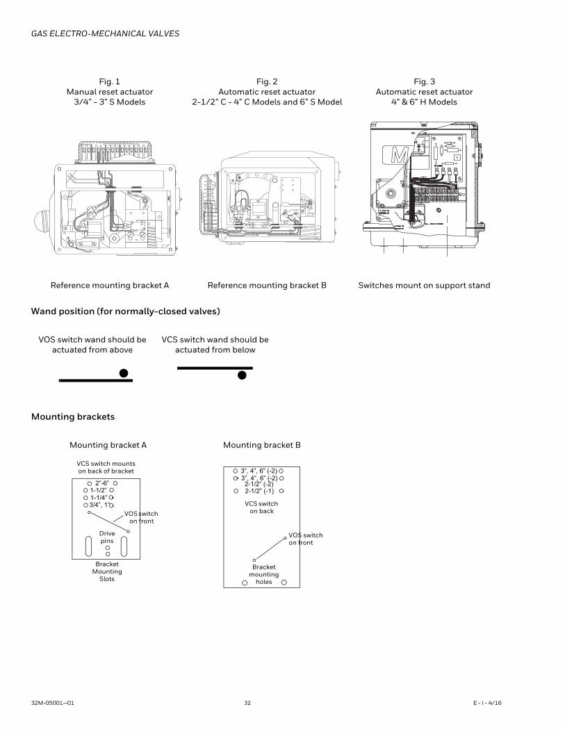
• Check illustrations below. If your valve uses a switch mounting bracket as in Fig. 1 & 2, mount switches to bracket using the mounting holes appropriate for valve type and size. For high capacity valves, mount switches on the support stand.
• Position bracket so VCS wand just touches top of actuator, then move downward slightly, depressing wand until switch clicks, then tighten mounting screws to hold this position.
• Pin bracket by drilling 1/8” diameter holes 1/4” deep into bracket mounting pad through drive pin holes, then tap drive pin in until flush (not required for high capacity valves).
• Route wires to wiring compartment as shown, then complete wiring connections and clean out metal drilling chips from previous procedure.
• Cycle valve, checking switch actuation points care-fully. (VCS actuates at top of stem stroke, VOS at bot-tom.) Simultaneously the valve body must be tested for switch continuity and seat leakage. Bend VOS switch wands slightly if necessary to insure valve is opening fully.
• Replace covers, then return valve to service.
E - i - 4/16 31 32M-05001—01
GAS ELECTRO-MECHANICAL VALVES
Wand position (for normally-closed valves)
Mounting brackets
Fig. 1Manual reset actuator
3/4” - 3” S Models
Fig. 2Automatic reset actuator
2-1/2” C - 4” C Models and 6” S Model
Fig. 3Automatic reset actuator
4” & 6” H Models
Reference mounting bracket A Reference mounting bracket B Switches mount on support stand
NCCOM#1 BLACK TO
#3 BLACK TO
BLACK TO MOTOR
TERMINAL #1
TERMINAL #3
NO
12
12 11 10 9 8 7 6 5 4 3 2 1
TO CLUTCH
VOS switch wand should be actuated from above
VCS switch wand should be actuated from below
Mounting bracket A Mounting bracket B
VCS switch mountson back of bracket
BracketMounting
Slots
2”-6”1-1/2”1-1/4”3/4”, 1”
Drive pins
VOS switch on front
3”, 4”, 6” (-2)3”, 4”, 6” (-2)2-1/2” (-2)2-1/2” (-1)
VCS switch on back
Bracket mounting
holes
VOS switchon front
32M-05001—01 32 E - i - 4/16
GAS ELECTRO-MECHANICAL VALVES
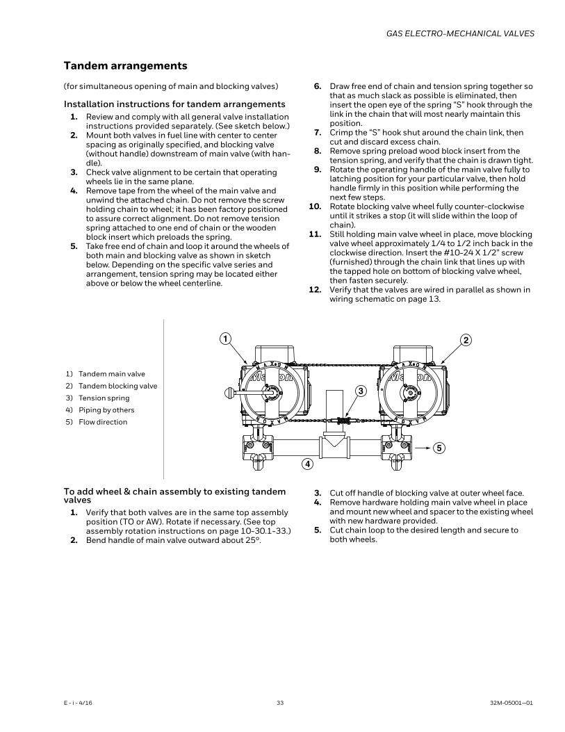
Tandem arrangements
(for simultaneous opening of main and blocking valves)
Installation instructions for tandem arrangements1. Review and comply with all general valve installation
instructions provided separately. (See sketch below.)2. Mount both valves in fuel line with center to center
spacing as originally specified, and blocking valve (without handle) downstream of main valve (with han-dle).
3. Check valve alignment to be certain that operating wheels lie in the same plane.
4. Remove tape from the wheel of the main valve and unwind the attached chain. Do not remove the screw holding chain to wheel; it has been factory positioned to assure correct alignment. Do not remove tension spring attached to one end of chain or the wooden block insert which preloads the spring.
5. Take free end of chain and loop it around the wheels of both main and blocking valve as shown in sketch below. Depending on the specific valve series and arrangement, tension spring may be located either above or below the wheel centerline.
6. Draw free end of chain and tension spring together so that as much slack as possible is eliminated, then insert the open eye of the spring “S” hook through the link in the chain that will most nearly maintain this position.
7. Crimp the “S” hook shut around the chain link, then cut and discard excess chain.
8. Remove spring preload wood block insert from the tension spring, and verify that the chain is drawn tight.
9. Rotate the operating handle of the main valve fully to latching position for your particular valve, then hold handle firmly in this position while performing the next few steps.
10. Rotate blocking valve wheel fully counter-clockwise until it strikes a stop (it will slide within the loop of chain).
11. Still holding main valve wheel in place, move blocking valve wheel approximately 1/4 to 1/2 inch back in the clockwise direction. Insert the #10-24 X 1/2” screw (furnished) through the chain link that lines up with the tapped hole on bottom of blocking valve wheel, then fasten securely.
12. Verify that the valves are wired in parallel as shown in wiring schematic on page 13.
To add wheel & chain assembly to existing tandem valves
1. Verify that both valves are in the same top assembly position (TO or AW). Rotate if necessary. (See top assembly rotation instructions on page 10-30.1-33.)
2. Bend handle of main valve outward about 25°.
3. Cut off handle of blocking valve at outer wheel face.4. Remove hardware holding main valve wheel in place
and mount new wheel and spacer to the existing wheel with new hardware provided.
5. Cut chain loop to the desired length and secure to both wheels.
1) Tandem main valve
2) Tandem blocking valve
3) Tension spring
4) Piping by others
5) Flow direction
1 2
3
5
4
E - i - 4/16 33 32M-05001—01
GAS ELECTRO-MECHANICAL VALVES
MAINTENANCE INSTRUCTIONS
MAXON electro-mechanical valves are endurance tested far in excess of the most stringent requirements of the various approval agencies. They are designed for long life even if frequently cycled, and to be as maintenance-free and trouble-free as possible. A valve operational test should be performed on an annual basis. If abnormal opening or closing is observed, the valve should be removed from service and your MAXON representative should be contacted. (See MAXON Technical Document 10-35.1.)
Valve leak test should be performed on an annual basis to assure continued safe and reliable operation. Every MAXON valve is operationally tested and meets the requirements of FCI 70-2 Class VI Seat Leakage when in good operable condition. Zero leakage may not be obtained in the field after it has been in service. For specific recommendations on leak test procedures, see MAXON Technical Document 10-35.2. Any valve that exceeds the allowable leakage, as set forth by your local codes or insurance requirements should be removed from service and your MAXON representative should be contacted.
Actuator assembly components require no field lubrication and should never be oiled.
Auxiliary switches, solenoids, motors, clutches or circuit boards may be replaced in the field.
WARNINGDo not attempt field repair of valve body or actuator. Any alterations void all warranties and can create potentially hazardous situations.
If foreign material or corrosive substances are present in the fuel line, it will be necessary to inspect the valve to make certain it is operating properly. If abnormal opening or closing is observed, the valve should be removed from service. Contact your MAXON representative for instructions.
Operator should be aware of and observe characteristic opening/closing action of the valve. Should operation ever become sluggish, remove valve from service and contact MAXON for recommendations.
Address inquiries to MAXON. Local worldwide offices may be located at www.maxoncorp.com. Include valve serial number and nameplate information.
32M-05001—01 34 E - i - 4/16
GAS ELECTRO-MECHANICAL VALVES
FITTING CERTIFICATE
We:
Maxon Corporation
Address:
201 E. 18th Street
Muncie, IN 47302
USA
Declare that all fittings produced at the above address within the following product group:
Maxon Series MA11, MM11, MA21 and MM21 Valves
Conform to all applicable provisions of the European Gas Appliance Directive.
Certification: Product Identification Number C87BQ83 applies
EC Surveillance: GL Industrial Services (Notified Body Number 0087)
This certificate issued by: Maxon Corporation
Name: Lora Davis
Title/Position: Product Engineering Manager
Date of issue: June 21, 2011
E - i - 4/16 35 32M-05001—01
GAS ELECTRO-MECHANICAL VALVES
For More InformationThe Honeywell Thermal Solutions family of products includes
Honeywell Combustion Safety, Eclipse, Exothermics, Hauck,
Kromschröder and Maxon. To learn more about our products,
visit ThermalSolutions.honeywell.com or contact your
Honeywell Sales Engineer.
Honeywell MAXON branded products201 E 18th Street
Muncie, IN 47302
USA
www.maxoncorp.com
Honeywell Process SolutionsHoneywell Thermal Solutions (HTS)
1250 West Sam Houston Parkway
South Houston, TX 77042
ThermalSolutions.honeywell
® U.S. Registered Trademark© 2016 Honeywell International Inc.32M-05001—01 M.S. 09-16Printed in United States