30mhz dual trace oscilloscope - farnell element14 · 30mhz dual trace oscilloscope model 72-6802...
TRANSCRIPT
30MHz Dual Trace Oscilloscope
Model 72-6802
USER MANUAL
This manual contains proprietary information, which is protected by copyrights. All rights are reserved. No part of this manual may be photocopied, reproduced or translated to another language without prior written consent of Tenma Test Equipment.
The information in this manual was correct at the time of printing. However, Tenma continues to improve products and reserves the rights to change specification, equipment, and maintenance procedures at any time without notice.
Tenma Test Equipment 405 S. Pioneer Blvd. Springboro Ohio, 45036
TABLE OF CONTENTS
3
Table of Contents SAFETY INSTRUCTIONS ................................................................................5
PRODUCT OVERVIEW .................................................................................. 10 Product Description ..................................................... 10 Main Features ................................................................. 11 Block Diagram ............................................................... 12
PANEL OVERVIEW ....................................................................................... 13 Front Panel Overview ................................................... 13 Display Controls ............................................................ 14 LCD Display .................................................................... 15 Horizontal Controls ...................................................... 16 Vertical Controls .......................................................... 17 Trigger Controls ........................................................... 19 Input Terminals ............................................................ 22 Rear Panel Overview ................................................... 23
SETUP .........................................................................................................24 Default Settings ........................................................... 24 Set up & Probe Compensation .................................... 26
MEASUREMENT........................................................................................... 28 Single Channel (Basic) Measurement ........................28 Dual Channel Measurement.........................................30 Waveform Addition/Subtraction ................................ 32 Frequency Measurement ............................................. 32 X-Y Mode .......................................................................33 Waveform Magnification .............................................. 34
FAQ ............................................................................................................ 35
72-6802 User Manual
APPENDIX ...................................................................................................37 Line Voltage & Fuse Replacement .............................. 37 Specifications .............................................................. 39 Declaration of Conformity ........................................... 41

SAFETY INSTRUCTIONS
5
SAFETY INSTRUCTIONS This chapter contains important safety instructions that you must follow when operating and storing this instrument. Read the following instructions before operating the instrument to ensure your safety and to keep it in best condition.
Safety symbols These safety symbols may appear in this manual or on the instrument.
WARNING Warning: Identifies conditions or practices that could result in injury or loss of life.
CAUTION Caution: Identifies conditions or practices that could result in damage to the instrument or to other properties.
DANGER: High Voltage
Attention: Refer to the Manual
Protective Conductor Terminal
Earth (Ground) Terminal
72-6802 User Manual
6
Safety guidelines
General Guideline
CAUTION
• Never connect a hazardous live voltage to the ground side of the BNC connectors. It might lead to fire or electric shock.
• Do not place heavy objects on the instrument.
• Avoid severe impacts or rough handlings that lead to damaging the instruments.
• Do not discharge static electricity onto the instruments.
• Use only mating connectors, not bare wires, for the terminals.
• Do not block the cooling fan opening.
• Do not perform measurements at power generating sources and building installation sites (See note below).
• Do not disassemble the instrument unless you are technically qualified.
• To prevent a permanent damage to the CRT phosphor, avoid excessively brightening the trace or holding a light spot for an unreasonably long time.
• Do not operate the instrument in a place where strong magnetic or electric field exists as it may disturb the measurement.
• Make sure the input voltage does not exceed the following values.
Input Terminal Maximum Input Voltage
CH1, CH2 input 300Vpeak
EXT TRIG input 300Vpeak
SAFETY INSTRUCTIONS
7
Probe input 600Vpeak
Z AXIS input 30Vpeak
(Measurement categories) EN 61010-1:2001 specifies the measurement categories and their requirements as follows. The 72-6802 falls under category II.
• Measurement category IV is for measurements performed at the source of low-voltage installations.
• Measurement category III is for measurements performed in building installations.
• Measurement category II is for measurements performed on the circuits directly connected to low voltage installations.
• Measurement category I is for measurements performed on circuits not directly connected to mains.
Power Supply
WARNING
• AC Input voltage: 115V/230V AC, 50/60Hz
• The power supply voltage should not fluctuate more than 15%.
• To avoid electric shock, connect the protective grounding conductor of the AC power cord to an earth ground.
Fuse
WARNING
• Fuse type: T0.63A/250V (AC 115V), T0.315A/250V (AC230V)
• Make sure the correct type of fuse is installed before power up.
• To ensure fire protection, replace the fuse only with the specified type and rating.
• Disconnect the power cord before fuse replacement.
• Make sure the cause of fuse blowout is fixed before replacing the fuse.
72-6802 User Manual
8
Cleaning the instrument
• Disconnect the power cord before cleaning the instrument.
• Use a soft cloth dampened in a solution of mild detergent and water. Do not spray any liquid into the instrument.
• Do not use chemicals containing harsh products such as benzene, toluene, xylene, and acetone.
Operation Environment
• Location: Indoor, no direct sunlight, dust free, almost non‐conductive pollution (See note below)
• Relative Humidity: < 85%, non‐condensing
• Altitude: < 2000m
• Temperature: 0°C to 40°C
(Pollution Degree) EN 61010-1:2001 specifies the pollution degrees and their requirements as follows. The 72-6802 falls under degree 2.
Pollution refers to “addition of foreign matter, solid, liquid, or gaseous (ionized gases), that may produce a reduction of dielectric strength or surface resistivity”.
• Pollution degree 1: No pollution or only dry, non-conductive pollution occurs. The pollution has no influence.
• Pollution degree 2: Normally only non-conductive pollution occurs. Occasionally, however, a temporary conductivity caused by condensation must be expected.
• Pollution degree 3: Conductive pollution occurs, or dry, non-conductive pollution occurs which becomes conductive due to condensation which is expected. In such conditions, equipment is normally protected against exposure to direct sunlight, precipitation, and full wind pressure, but neither temperature nor humidity is controlled.
Storage environment
• Location: Indoor
• Relative Humidity: < 70%
• Temperature: –10°C to 70°C
SAFETY INSTRUCTIONS
9
Power cord for the United Kingdom When using the instrument in the United Kingdom, make sure the power cord meets the following safety instructions.
NOTE: This lead/appliance must only be wired by competent persons
WARNING: THIS APPLIANCE MUST BE EARTHED IMPORTANT: The wires in this lead are coloured in accordance with the following code:
Green/ Yellow: Earth Blue: Neutral Brown: Live (Phase)
As the colours of the wires in mains leads may not correspond with the colours marking identified in your plug/appliance, proceed as follows: The wire which is coloured Green & Yellow must be connected to the Earth terminal marked with the letter E or by the earth symbol or coloured Green or Green & Yellow. The wire which is coloured Blue must be connected to the terminal which is marked with the letter N or coloured Blue or Black. The wire which is coloured Brown must be connected to the terminal marked with the letter L or P or coloured Brown or Red. If in doubt, consult the instructions provided with the equipment or contact the supplier. This cable/appliance should be protected by a suitably rated and approved HBC mains fuse: refer to the rating information on the equipment and/or user instructions for details. As a guide, cable of 0.75mm2 should be protected by a 3A or 5A fuse. Larger conductors would normally require 13A types, depending on the connection method used. Any moulded mains connector that requires removal /replacement must be destroyed by removal of any fuse & fuse carrier and disposed of immediately, as a plug with bared wires is hazardous if a engaged in live socket. Any re-wiring must be carried out in accordance with the information detailed on this label.
72-6802 User Manual
10
PRODUCT OVERVIEW
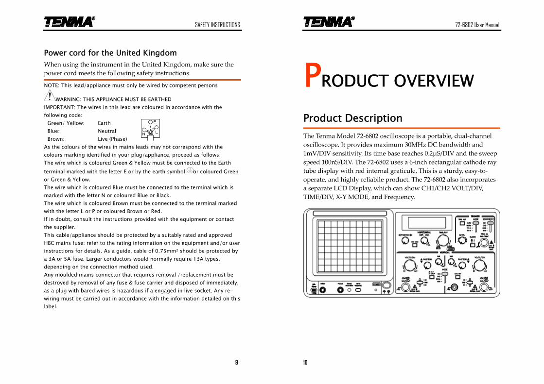
Product Description
The Tenma Model 72‐6802 oscilloscope is a portable, dual‐channel oscilloscope. It provides maximum 30MHz DC bandwidth and 1mV/DIV sensitivity. Its time base reaches 0.2μS/DIV and the sweep speed 100nS/DIV. The 72‐6802 uses a 6‐inch rectangular cathode ray tube display with red internal graticule. This is a sturdy, easy‐to‐operate, and highly reliabile product. The 72‐6802 also incorporates a separate LCD Display, which can show CH1/CH2 VOLT/DIV, TIME/DIV, X‐Y MODE, and Frequency.
PRODUCT OVERVIEW
11
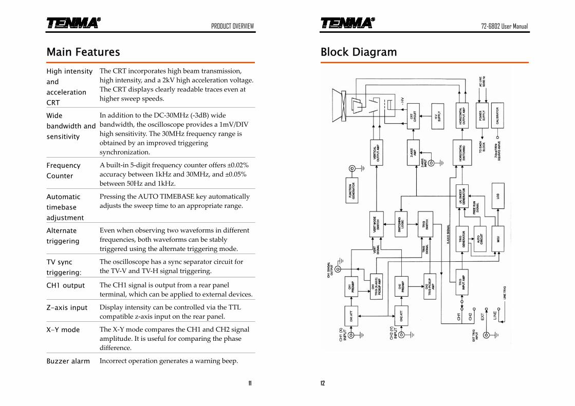
Main Features
High intensity and acceleration CRT
The CRT incorporates high beam transmission, high intensity, and a 2kV high acceleration voltage. The CRT displays clearly readable traces even at higher sweep speeds.
Wide bandwidth and sensitivity
In addition to the DC‐30MHz (‐3dB) wide bandwidth, the oscilloscope provides a 1mV/DIV high sensitivity. The 30MHz frequency range is obtained by an improved triggering synchronization.
Frequency Counter
A built‐in 5‐digit frequency counter offers ±0.02% accuracy between 1kHz and 30MHz, and ±0.05% between 50Hz and 1kHz.
Automatic timebase adjustment
Pressing the AUTO TIMEBASE key automatically adjusts the sweep time to an appropriate range.
Alternate triggering
Even when observing two waveforms in different frequencies, both waveforms can be stably triggered using the alternate triggering mode.
TV sync triggering:
The oscilloscope has a sync separator circuit for the TV‐V and TV‐H signal triggering.
CH1 output The CH1 signal is output from a rear panel terminal, which can be applied to external devices.
Z-axis input Display intensity can be controlled via the TTL compatible z‐axis input on the rear panel.
X-Y mode The X‐Y mode compares the CH1 and CH2 signal amplitude. It is useful for comparing the phase difference.
Buzzer alarm Incorrect operation generates a warning beep.
72-6802 User Manual
12
Block Diagram
PANEL OVERVIEW
13
PANEL OVERVIEW
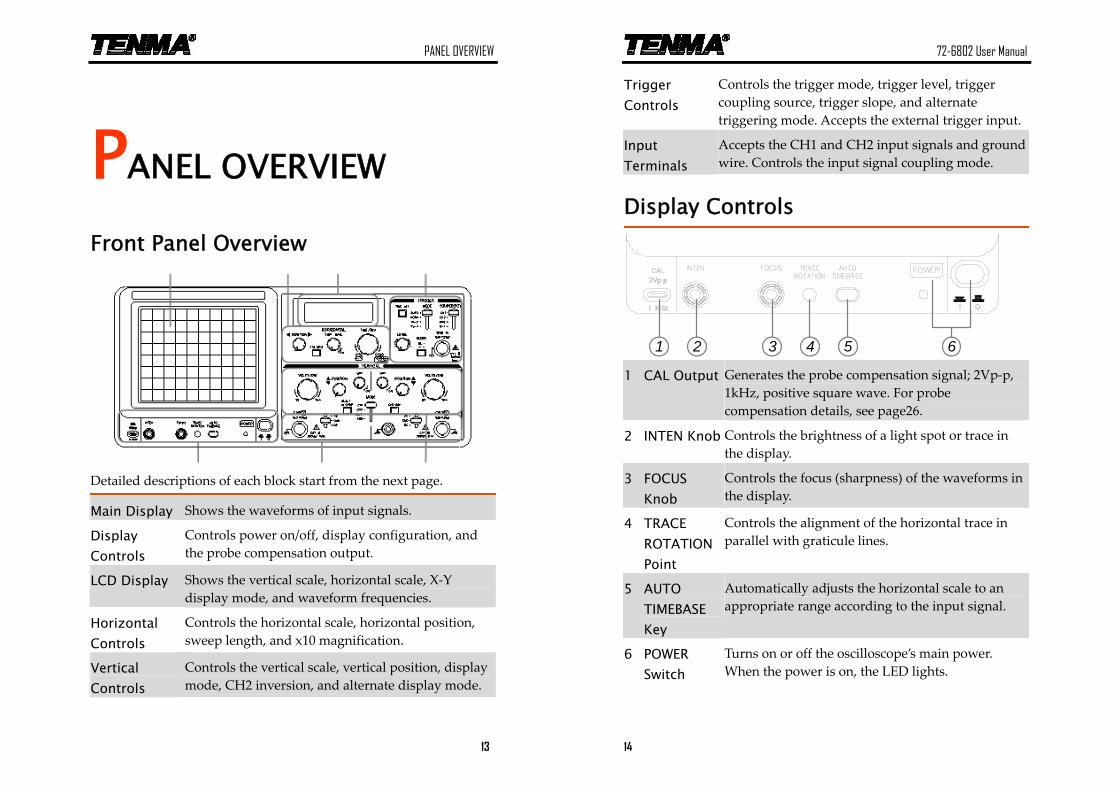
Front Panel Overview
Detailed descriptions of each block start from the next page.
Main Display Shows the waveforms of input signals.
Display Controls
Controls power on/off, display configuration, and the probe compensation output.
LCD Display Shows the vertical scale, horizontal scale, X‐Y display mode, and waveform frequencies.
Horizontal Controls
Controls the horizontal scale, horizontal position, sweep length, and x10 magnification.
Vertical Controls
Controls the vertical scale, vertical position, display mode, CH2 inversion, and alternate display mode.
72-6802 User Manual
14
Trigger Controls
Controls the trigger mode, trigger level, trigger coupling source, trigger slope, and alternate triggering mode. Accepts the external trigger input.
Input Terminals
Accepts the CH1 and CH2 input signals and ground wire. Controls the input signal coupling mode.
Display Controls
654321 1 CAL Output Generates the probe compensation signal; 2Vp‐p,
1kHz, positive square wave. For probe compensation details, see page26.
2 INTEN Knob Controls the brightness of a light spot or trace in the display.
3 FOCUS Knob
Controls the focus (sharpness) of the waveforms in the display.
4 TRACE ROTATION Point
Controls the alignment of the horizontal trace in parallel with graticule lines.
5 AUTO TIMEBASE Key
Automatically adjusts the horizontal scale to an appropriate range according to the input signal.
6 POWER Switch
Turns on or off the oscilloscope’s main power. When the power is on, the LED lights.
PANEL OVERVIEW
15
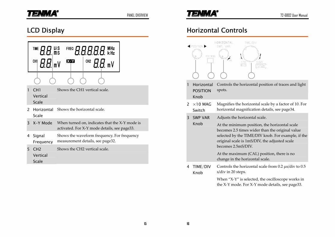
LCD Display
1 CH1
Vertical Scale
Shows the CH1 vertical scale.
2 Horizontal Scale
Shows the horizontal scale.
3 X-Y Mode When turned on, indicates that the X‐Y mode is activated. For X‐Y mode details, see page33.
4 Signal Frequency
Shows the waveform frequency. For frequency measurement details, see page32.
5 CH2 Vertical Scale
Shows the CH2 vertical scale.
72-6802 User Manual
16
Horizontal Controls
1 Horizontal
POSITION Knob
Controls the horizontal position of traces and light spots.
2 ×10 MAG Switch
Magnifies the horizontal scale by a factor of 10. For horizontal magnification details, see page34.
3 SWP VAR Knob
Adjusts the horizontal scale.
At the minimum position, the horizontal scale becomes 2.5 times wider than the original value selected by the TIME/DIV knob. For example, if the original scale is 1mS/DIV, the adjusted scale becomes 2.5mS/DIV.
At the maximum (CAL) position, there is no change in the horizontal scale.
4 TIME/DIV Knob
Controls the horizontal scale from 0.2 μs/div to 0.5 s/div in 20 steps.
When “X‐Y” is selected, the oscilloscope works in the X‐Y mode. For X‐Y mode details, see page33.
PANEL OVERVIEW
17
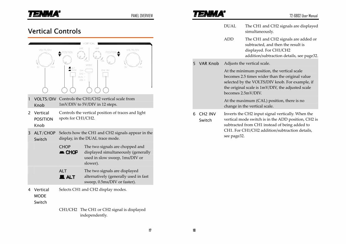
Vertical Controls
1 VOLTS/DIV Knob
Controls the CH1/CH2 vertical scale from 1mV/DIV to 5V/DIV in 12 steps.
2 Vertical POSITION Knob
Controls the vertical position of traces and light spots for CH1/CH2.
3 ALT/CHOP Switch
Selects how the CH1 and CH2 signals appear in the display, in the DUAL trace mode.
CHOP
The two signals are chopped and displayed simultaneously (generally used in slow sweep, 1ms/DIV or slower).
ALT
The two signals are displayed alternatively (generally used in fast sweep, 0.5ms/DIV or faster).
4 Vertical MODE Switch
Selects CH1 and CH2 display modes.
CH1/CH2 The CH1 or CH2 signal is displayed independently.
72-6802 User Manual
18
DUAL The CH1 and CH2 signals are displayed simultaneously.
ADD The CH1 and CH2 signals are added or subtracted, and then the result is displayed. For CH1/CH2 addition/subtraction details, see page32.
5 VAR Knob Adjusts the vertical scale.
At the minimum position, the vertical scale becomes 2.5 times wider than the original value selected by the VOLTS/DIV knob. For example, if the original scale is 1mV/DIV, the adjusted scale becomes 2.5mV/DIV.
At the maximum (CAL) position, there is no change in the vertical scale.
6 CH2 INV Switch
Inverts the CH2 input signal vertically. When the vertical mode switch is in the ADD position, CH2 is subtracted from CH1 instead of being added to CH1. For CH1/CH2 addition/subtraction details, see page32.
PANEL OVERVIEW
19
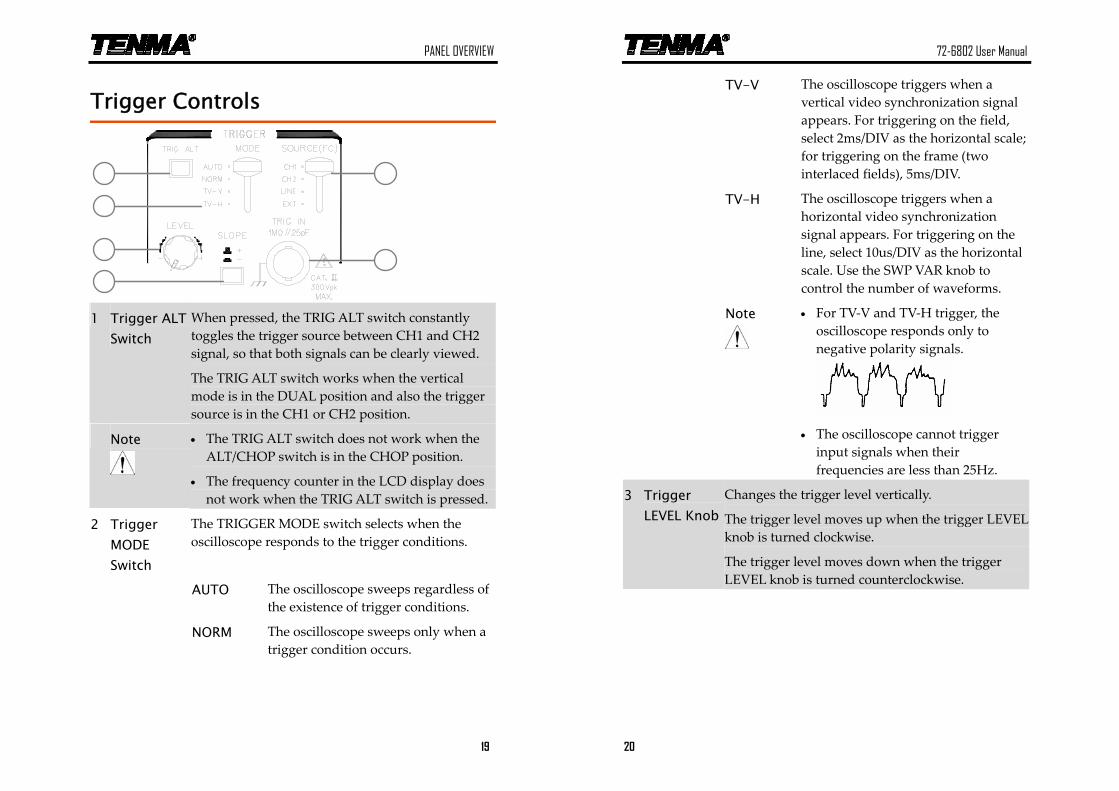
Trigger Controls
1 Trigger ALT
Switch When pressed, the TRIG ALT switch constantly toggles the trigger source between CH1 and CH2 signal, so that both signals can be clearly viewed.
The TRIG ALT switch works when the vertical mode is in the DUAL position and also the trigger source is in the CH1 or CH2 position.
Note
• The TRIG ALT switch does not work when the ALT/CHOP switch is in the CHOP position.
• The frequency counter in the LCD display does not work when the TRIG ALT switch is pressed.
2 Trigger MODE Switch
The TRIGGER MODE switch selects when the oscilloscope responds to the trigger conditions.
AUTO The oscilloscope sweeps regardless of the existence of trigger conditions.
NORM The oscilloscope sweeps only when a trigger condition occurs.
72-6802 User Manual
20
TV-V The oscilloscope triggers when a vertical video synchronization signal appears. For triggering on the field, select 2ms/DIV as the horizontal scale; for triggering on the frame (two interlaced fields), 5ms/DIV.
TV-H The oscilloscope triggers when a horizontal video synchronization signal appears. For triggering on the line, select 10us/DIV as the horizontal scale. Use the SWP VAR knob to control the number of waveforms.
Note
• For TV‐V and TV‐H trigger, the oscilloscope responds only to negative polarity signals.
• The oscilloscope cannot trigger
input signals when their frequencies are less than 25Hz.
3 Trigger LEVEL Knob
Changes the trigger level vertically.
The trigger level moves up when the trigger LEVEL knob is turned clockwise.
The trigger level moves down when the trigger LEVEL knob is turned counterclockwise.
PANEL OVERVIEW
21
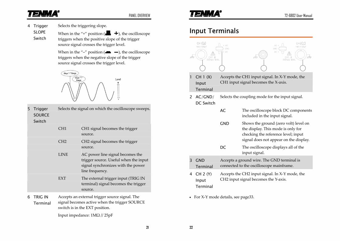
4 Trigger SLOPE Switch
Selects the triggering slope.
When in the “+” position ( ), the oscilloscope triggers when the positive slope of the trigger source signal crosses the trigger level.
When in the “–” position ( ), the oscilloscope triggers when the negative slope of the trigger source signal crosses the trigger level.
5 Trigger
SOURCE Switch
Selects the signal on which the oscilloscope sweeps.
CH1 CH1 signal becomes the trigger source.
CH2 CH2 signal becomes the trigger source.
LINE AC power line signal becomes the trigger source. Useful when the input signal synchronizes with the power line frequency.
EXT The external trigger input (TRIG IN terminal) signal becomes the trigger source.
6 TRIG IN Terminal
Accepts an external trigger source signal. The signal becomes active when the trigger SOURCE switch is in the EXT position.
Input impedance: 1MΩ // 25pF
72-6802 User Manual
22
Input Terminals
1 CH 1 (X)
Input Terminal
Accepts the CH1 input signal. In X‐Y mode, the CH1 input signal becomes the X‐axis.
2 AC/GND/ DC Switch
Selects the coupling mode for the input signal.
AC The oscilloscope block DC components included in the input signal.
GND Shows the ground (zero volt) level on the display. This mode is only for checking the reference level; input signal does not appear on the display.
DC The oscilloscope displays all of the input signal.
3 GND Terminal
Accepts a ground wire. The GND terminal is connected to the oscilloscope mainframe.
4 CH 2 (Y) Input Terminal
Accepts the CH2 input signal. In X‐Y mode, the CH2 input signal becomes the Y‐axis.
• For X‐Y mode details, see page33.
PANEL OVERVIEW
23
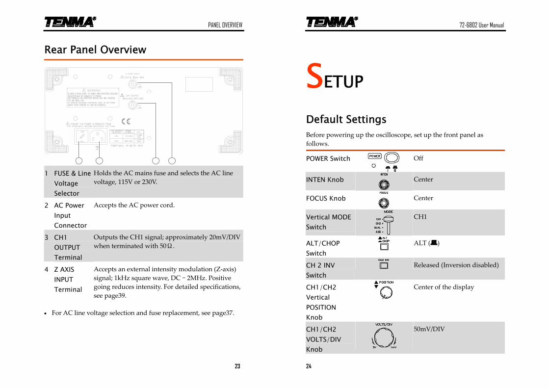
Rear Panel Overview
1 FUSE & Line Voltage Selector
Holds the AC mains fuse and selects the AC line voltage, 115V or 230V.
2 AC Power Input Connector
Accepts the AC power cord.
3 CH1 OUTPUT Terminal
Outputs the CH1 signal; approximately 20mV/DIV when terminated with 50Ω.
4 Z AXIS INPUT Terminal
Accepts an external intensity modulation (Z‐axis) signal; 1kHz square wave, DC – 2MHz. Positive going reduces intensity. For detailed specifications, see page39.
• For AC line voltage selection and fuse replacement, see page37.
72-6802 User Manual
24
SETUP
Default Settings Before powering up the oscilloscope, set up the front panel as follows.
POWER Switch
Off
INTEN Knob
Center
FOCUS Knob
Center
Vertical MODE Switch
CH1
ALT/CHOP Switch
ALT ( )
CH 2 INV Switch
Released (Inversion disabled)
CH1/CH2 Vertical POSITION Knob
Center of the display
CH1/CH2 VOLTS/DIV Knob
50mV/DIV
SETUP
25
CH1/CH2 VARIABLE Knob
CAL
CH1/CH2 Coupling Switch
AC
Trigger SOURCE Switch
CH1
Trigger SLOPE Switch
+ (Positive slope)
TRIG ALT Switch
Released (alternating trigger disabled)
Trigger MODE Switch
AUTO
TIME/DIV Knob
0.5ms/DIV
Horizontal SWP.VAR Knob
CAL
Horizontal POSITION Knob
Center of the display
x10 MAG Switch
Released (x10 maginification disabled)
72-6802 User Manual
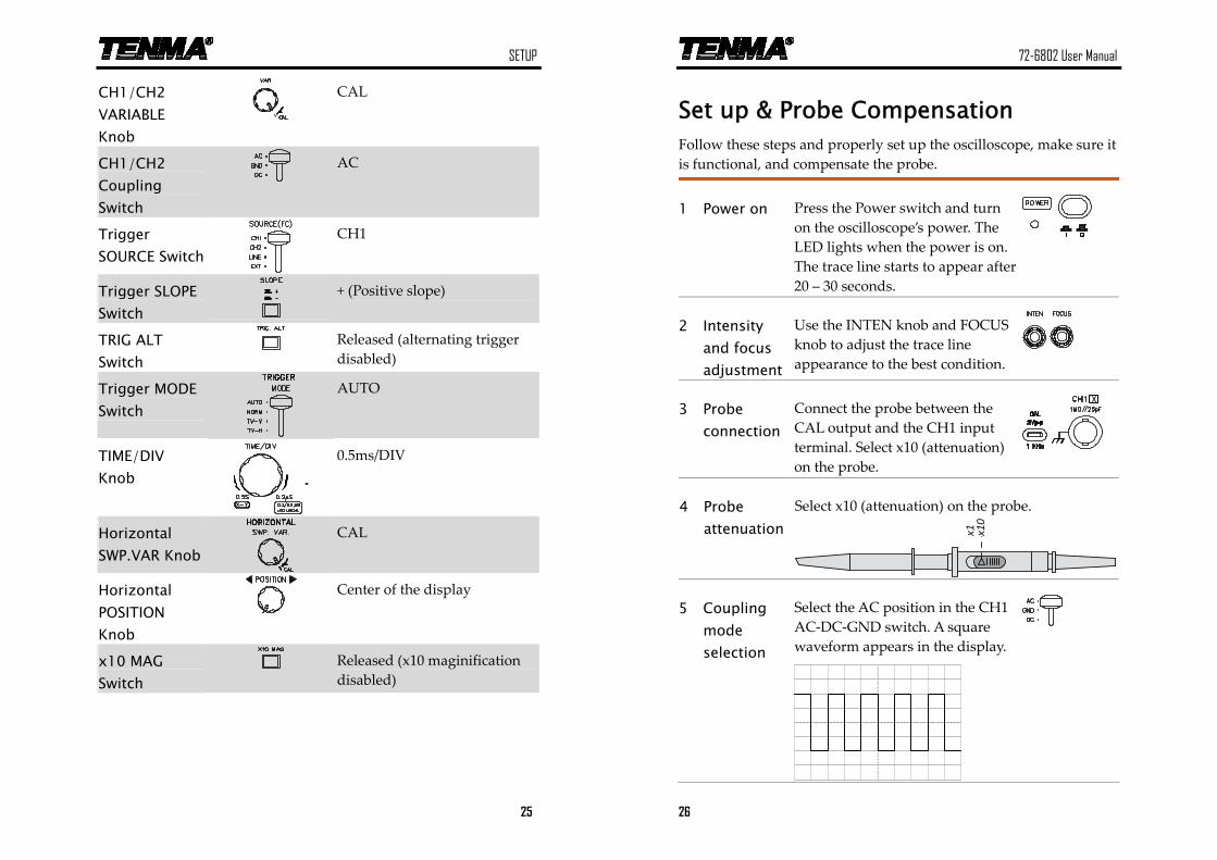
26
Set up & Probe Compensation Follow these steps and properly set up the oscilloscope, make sure it is functional, and compensate the probe.
1 Power on Press the Power switch and turn on the oscilloscope’s power. The LED lights when the power is on. The trace line starts to appear after 20 – 30 seconds.
2 Intensity and focus adjustment
Use the INTEN knob and FOCUS knob to adjust the trace line appearance to the best condition.
3 Probe connection
Connect the probe between the CAL output and the CH1 input terminal. Select x10 (attenuation) on the probe.
Select x10 (attenuation) on the probe. 4 Probe attenuation x1
0x1
5 Coupling mode selection
Select the AC position in the CH1 AC‐DC‐GND switch. A square waveform appears in the display.
SETUP
27
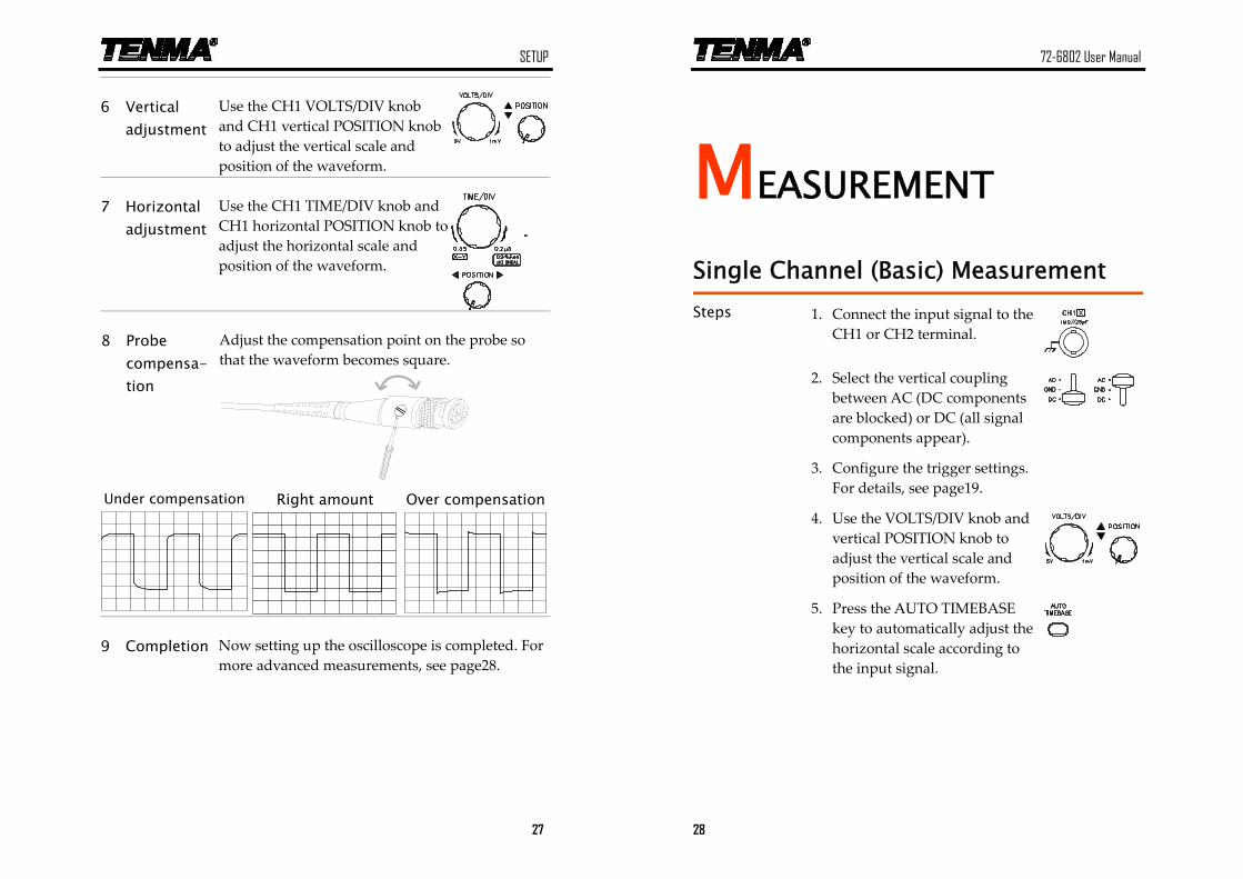
6 Vertical adjustment
Use the CH1 VOLTS/DIV knob and CH1 vertical POSITION knob to adjust the vertical scale and position of the waveform.
7 Horizontal adjustment
Use the CH1 TIME/DIV knob and CH1 horizontal POSITION knob to adjust the horizontal scale and position of the waveform.
Adjust the compensation point on the probe so that the waveform becomes square.
8 Probe compensa-tion
Under compensation Right amount Over compensation
9 Completion Now setting up the oscilloscope is completed. For more advanced measurements, see page28.
72-6802 User Manual
28
MEASUREMENT
Single Channel (Basic) Measurement
Steps 1. Connect the input signal to the CH1 or CH2 terminal.
2. Select the vertical coupling between AC (DC components are blocked) or DC (all signal components appear).
3. Configure the trigger settings. For details, see page19.
4. Use the VOLTS/DIV knob and vertical POSITION knob to adjust the vertical scale and position of the waveform.
5. Press the AUTO TIMEBASE key to automatically adjust the horizontal scale according to the input signal.
MEASUREMENT
29
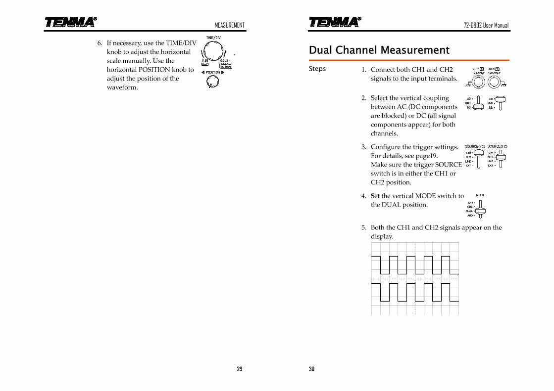
6. If necessary, use the TIME/DIV knob to adjust the horizontal scale manually. Use the horizontal POSITION knob to adjust the position of the waveform.
72-6802 User Manual
30
Dual Channel Measurement
Steps 1. Connect both CH1 and CH2 signals to the input terminals.
2. Select the vertical coupling between AC (DC components are blocked) or DC (all signal components appear) for both channels.
3. Configure the trigger settings. For details, see page19. Make sure the trigger SOURCE switch is in either the CH1 or CH2 position.
4. Set the vertical MODE switch to the DUAL position.
5. Both the CH1 and CH2 signals appear on the display.
MEASUREMENT
31
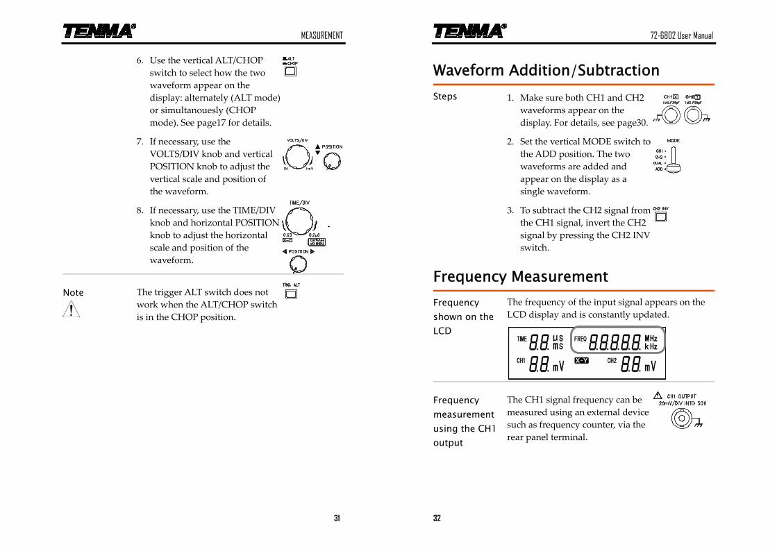
6. Use the vertical ALT/CHOP switch to select how the two waveform appear on the display: alternately (ALT mode) or simultanouesly (CHOP mode). See page17 for details.
7. If necessary, use the VOLTS/DIV knob and vertical POSITION knob to adjust the vertical scale and position of the waveform.
8. If necessary, use the TIME/DIV knob and horizontal POSITION knob to adjust the horizontal scale and position of the waveform.
Note
The trigger ALT switch does not work when the ALT/CHOP switch is in the CHOP position.
72-6802 User Manual
32
Waveform Addition/Subtraction
Steps 1. Make sure both CH1 and CH2 waveforms appear on the display. For details, see page30.
2. Set the vertical MODE switch to the ADD position. The two waveforms are added and appear on the display as a single waveform.
3. To subtract the CH2 signal from the CH1 signal, invert the CH2 signal by pressing the CH2 INV switch.
Frequency Measurement
Frequency shown on the LCD
The frequency of the input signal appears on the LCD display and is constantly updated.
Frequency measurement using the CH1 output
The CH1 signal frequency can be measured using an external device such as frequency counter, via the rear panel terminal.
MEASUREMENT
33
X-Y Mode
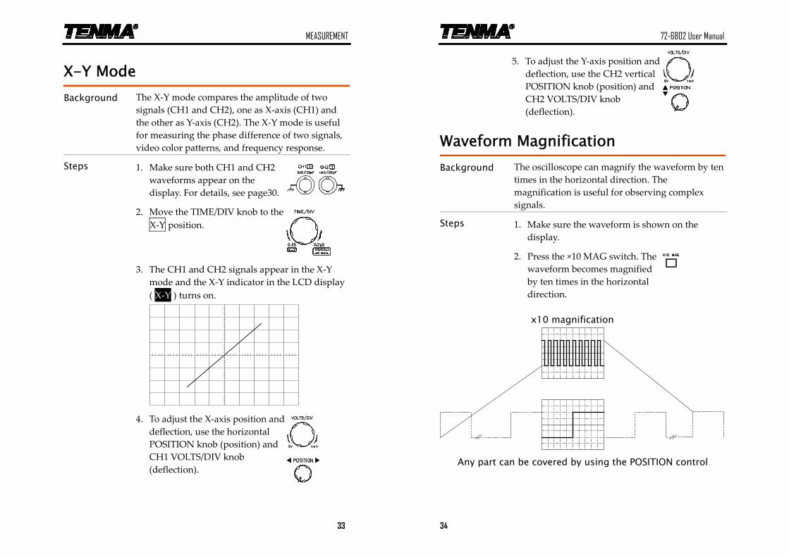
Background The X‐Y mode compares the amplitude of two signals (CH1 and CH2), one as X‐axis (CH1) and the other as Y‐axis (CH2). The X‐Y mode is useful for measuring the phase difference of two signals, video color patterns, and frequency response.
Steps 1. Make sure both CH1 and CH2 waveforms appear on the display. For details, see page30.
2. Move the TIME/DIV knob to the X‐Y position.
3. The CH1 and CH2 signals appear in the X‐Y mode and the X‐Y indicator in the LCD display ( X‐Y ) turns on.
4. To adjust the X‐axis position and deflection, use the horizontal POSITION knob (position) and CH1 VOLTS/DIV knob (deflection).
72-6802 User Manual
34
5. To adjust the Y‐axis position and deflection, use the CH2 vertical POSITION knob (position) and CH2 VOLTS/DIV knob (deflection).
Waveform Magnification
Background The oscilloscope can magnify the waveform by ten times in the horizontal direction. The magnification is useful for observing complex signals.
Steps 1. Make sure the waveform is shown on the display.
2. Press the ×10 MAG switch. The waveform becomes magnified by ten times in the horizontal direction.
x10 magnification
Any part can be covered by using the POSITION control
FAQ
35
FAQ
The probe waveform is distorted.
You might need to compensate the probe. For details, see page26. Note that frequency accuracy and duty factor are not specified for the probe compensation waveform and therefore it should not be used for reference purpose.
The trace line does not appear on the display.
Make sure that the trigger mode is in the AUTO mode. In the NORMAL mode, the trace does not appear unless a trigger condition occurs.
The alternate trigger (TRIG ALT switch) does not work.
Make sure that the ALT/CHOP switch is released (ALT position). The TRIG ALT switch does not work in the CHOP mode.
The frequency counter in the LCD display does not work.
Make sure that the TRIG ALT switch is not pressed. The frequency counter does not work in the alternate trigger mode.
The TV trigger does not work.
Make sure that the video synchronization signal is positive. The TV‐V/TV‐H trigger works only when the synchronization signal is negative.
72-6802 User Manual
36
The input signal does not appear on the display.
Check the following settings.
• The coupling mode is not set at the GND mode, in which the waveform does not appear on the display. See page22 for details.
• The appropriate trigger source is selected. See page19 for details.
The oscilloscope accuracy does not match the specifications.
Make sure the oscilloscope is powered on for at least 30 minutes, within +20°C – +30°C. This is necessary to stabilize the oscilloscope.
For more information, contact your local dealer, Tenma website www.tenma.com., or MCM Electronics at www.mcmelectronics.com.
APPENDIX
37
APPENDIX
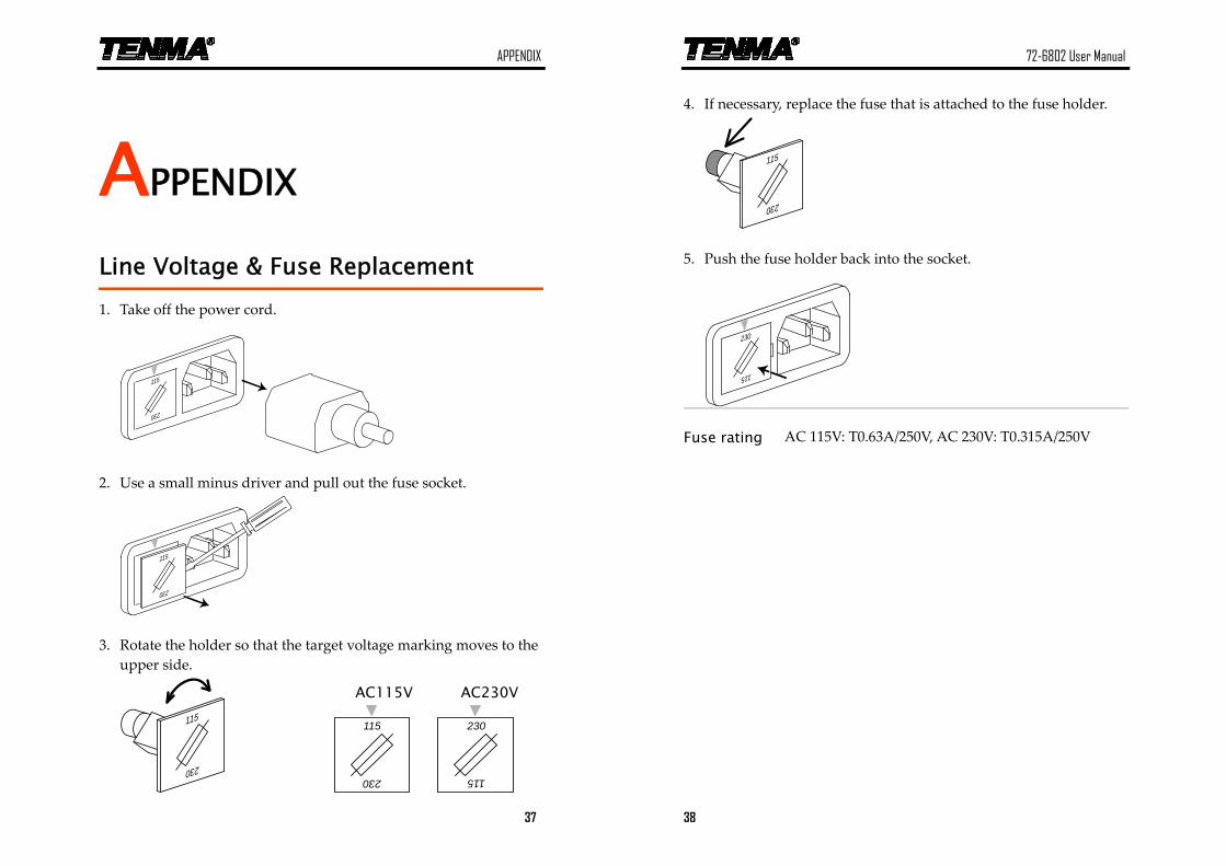
Line Voltage & Fuse Replacement
1. Take off the power cord.
115
230
2. Use a small minus driver and pull out the fuse socket.
115
230
3. Rotate the holder so that the target voltage marking moves to the upper side.
115
230
AC115V
230
115
AC230V
115
230
72-6802 User Manual
38
4. If necessary, replace the fuse that is attached to the fuse holder.
115
230
5. Push the fuse holder back into the socket.
230
115
Fuse rating AC 115V: T0.63A/250V, AC 230V: T0.315A/250V
APPENDIX
39
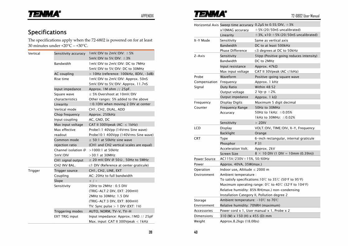
Specifications The specifications apply when the 72‐6802 is powered on for at least 30 minutes under +20°C – +30°C.
Vertical Sensitivity accuracy 1mV/DIV to 2mV/DIV: ±5%
5mV/DIV to 5V/DIV: ±3% Bandwidth 1mV/DIV to 2mV/DIV: DC to 7MHz
5mV/DIV to 5V/DIV: DC to 30MHz AC coupling > 10Hz (reference: 100kHz, 8DIV, –3dB) Rise time 1mV/DIV to 2mV/DIV: Approx. 50nS
5mV/DIV to 5V/DIV: Approx. 11.7nS Input impedance Approx. 1M ohm // 25pF. Square wave
characteristics ≤ 5% Overshoot at 10mV/DIV Other ranges: 5% added to the above
Linearity ±0.1DIV when moving 2 DIV at center Vertical mode CH1, CH2, DUAL, ADD Chop frequency Approx. 250kHz Input coupling AC, GND, DC Max input voltage CAT II 300Vpeak (AC: ≤ 1kHz) Max effective
readout Probe1:1 40Vpp (14Vrms Sine wave) Probe10:1 400Vpp (140Vrms Sine wave)
Common mode rejection ratio
≥ 50:1 at 50kHz sine wave (CH1 and CH2 vertical scales are equal)
Channel isolation @ 5mV/DIV
>1000:1 at 50kHz >30:1 at 30MHz
CH1 signal output ≥ 20 mV/DIV @ 50Ω, 50Hz to 5MHz CH2 INV BAL. ≤1 DIV (Reference at center graticule) Trigger Trigger source CH1, CH2, LINE, EXT Coupling AC: 20Hz to full bandwidth Slope + / - Sensitivity 20Hz to 2MHz : 0.5 DIV
(TRIG-ALT:2 DIV, EXT: 200mV) 2MHz to 30MHz: 1.5 DIV (TRIG-ALT:3 DIV, EXT: 800mV) TV: Sync pulse > 1 DIV (EXT: 1V)
Triggering modes AUTO, NORM, TV-V, TV-H EXT TRIG input Input impedance: Approx.:1MΩ // 25pF
Max. input: CAT II 300Vpeak < 1kHz
72-6802 User Manual
40
Horizontal Axis Sweep time accuracy 0.2µS to 0.5S/DIV, ±3% x10MAG accuracy ±5% (20/50nS uncalibrated) Linearity ±3%, x10:±5% (20/50nS uncalibrated) X-Y Mode Sensitivity Same as vertical axis Bandwidth DC to at least 500kHz Phase Difference ≤3 degrees at DC to 50kHz Z-Axis Sensitivity 5Vpp (Positive going reduces intensity) Bandwidth DC to 2MHz Input resistance Approx. 47kΩ Max input voltage CAT II 30Vpeak (AC ≤1kHz)
Waveform Positive-going square wave Frequency Approx. 1 kHz Duty Ratio Within 48:52 Output voltage 2 Vp-p ±2%.
Probe Compensation Signal
Output impedance Approx. 1 kΩ Display Digits Maximum 5 digit decimal Frequency
Counter Frequency Range 50Hz to 30MHz Accuracy 50Hz to 1kHz: ±0.05%
1kHz to 30MHz: ±0.02% Sensitivity > 2DIV LCD Display VOLT/DIV, TIME/DIV, X-Y, Frequency Backlight Orange CRT Type 6-inch rectangular, internal graticule Phosphor P 31 Acceleration Volt. Approx. 2kV Screen Size 8 × 10 DIV (1 DIV = 10mm (0.39in)) Power Source AC115V/230V±15%, 50/60Hz Power Approx. 40VA, 35W(max.) Operation Environment
Indoor use, Altitude ≤ 2000 m Ambient temperature : To satisfy specifications:10 to 35 (50°F to 95°F) Maximum operating range: 0 to 40 (32°F to 104°F) Relative humidity: 85% RH(max.) non-condensing Installation Category II, Pollution degree 2
Storage Environment
Ambient temperature: -10 to 70 Relative humidity: 70%RH (maximum)
Accessories Power cord x 1, User manual x 1, Probe x 2 Dimensions 310 (W) x 150 (H) x 455 (D) mm Weight Approx.8.2kgs (18.0lbs)
APPENDIX
41
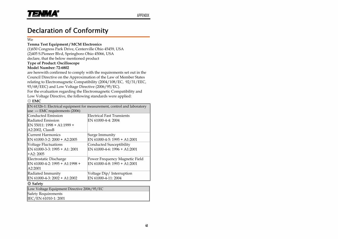
Declaration of Conformity
We Tenma Test Equipment / MCM Electronics (1)650 Congress Park Drive, Centerville Ohio 45459, USA (2)405 S.Pioneer Blvd, Springboro Ohio 45066, USA declare, that the below mentioned product Type of Product: Oscilloscope Model Number: 72-6802 are herewith confirmed to comply with the requirements set out in the Council Directive on the Approximation of the Law of Member States relating to Electromagnetic Compatibility (2004/108/EC, 92/31/EEC, 93/68/EEC) and Low Voltage Directive (2006/95/EC). For the evaluation regarding the Electromagnetic Compatibility and Low Voltage Directive, the following standards were applied: EMC EN 61326-1: Electrical equipment for measurement, control and laboratory use –– EMC requirements (2006) Conducted Emission Radiated Emission EN 55011: 1998 + A1:1999 + A2:2002, ClassB
Electrical Fast Transients EN 61000-4-4: 2004
Current Harmonics EN 61000-3-2: 2000 + A2:2005
Surge Immunity EN 61000-4-5: 1995 + A1:2001
Voltage Fluctuations EN 61000-3-3: 1995 + A1: 2001 +A2: 2005
Conducted Susceptibility EN 61000-4-6: 1996 + A1:2001
Electrostatic Discharge EN 61000-4-2: 1995 + A1:1998 + A2:2001
Power Frequency Magnetic Field EN 61000-4-8: 1993 + A1:2001
Radiated Immunity EN 61000-4-3: 2002 + A1:2002
Voltage Dip/ Interruption EN 61000-4-11: 2004
Safety Low Voltage Equipment Directive 2006/95/EC Safety Requirements IEC/EN 61010-1: 2001