30131644 copper alloys wrought
TRANSCRIPT

COPPER ALLOYS,WROUGHT
1. Introduction
Among the metals of commercial importance, copper [7440-50-8] (qv) and itsalloys are surpassed only by iron (qv) and aluminum (see ALUMINUM AND ALUMI-
NUM ALLOYS) in worldwide consumption. Typically, copper is alloyed with otherelements to provide a broad range of mechanical, physical, and chemical proper-ties that account for widespread use. The principal characteristics of copperalloys are moderate-to-high electrical and thermal conductivities combinedwith good corrosion resistance, good strength, good formability, unique decora-tive appearance, and moderate cost (see also CORROSION AND CORROSION CONTROL).Most copper alloys are readily hot and cold formed, joined (soldered, brazed,and welded), and plated (see also SOLDERS AND BRAZING FILLER METALS; WELDING).
Chief consumers of copper and copper alloys are the building constructionindustry for electrical wire, tubing, builder’s hardware, plumbing, and sheathing(see BUILDING MATERIALS, SURVEY); electrical and electronic products for motors,
720 COPPER ALLOYS, WROUGHT Vol. 7
Kirk-Othmer Encyclopedia of Chemical Technology. Copyright John Wiley & Sons, Inc. All rights reserved.

connectors, printed circuit copper foil, and leadframes (see ELECTRICAL CONNEC-
TORS; ELECTRONIC MATERIALS; INTEGRATED CIRCUITS); and the transportation (qv) sectorfor radiators and wiring harnesses. Other industries include ordnance, powerutilities, coinage, decorative hardware, musical instruments and flatware. (seeEXPLOSIVES AND PROPELLANTS; POWER GENERATION).
2. Alloy Designations
Copper is primarily alloyed to increase strength. Such alloying can, however,strongly affect other properties; eg electrical and thermal conductivities, corro-sion resistance, formability, and color. Elements typically added to copper,both singly and in combination are zinc, tin, nickel, iron, aluminum, silicon, sil-ver, chromium, titanium, and beryllium.
Copper and its alloys are classified in the United States by compositionaccording to the Unified Numbering System (UNS) for metals and alloys.Wrought materials are assigned five-digit numerical designations which rangefrom C10100 through C79999, but only the first three or sometimes four numer-als are used for brevity. The designations of wrought copper alloys are given inTable 1. Designations that start with numeral 8 or 9 are reserved for cast alloys(see COPPER ALLOYS, CAST COPPER ALLOYS) (1).
Under the UNS designation system, coppers that contain no or very smallamounts of intentional alloy additives (including Ag, P, Zr, Mg, Sn), ie, 99.3 wt%minimum copper, are distinguished from the dilute copper alloys. These latterare called the high coppers and contain a minimum of 96 wt% copper. Alloysof copper are grouped according to the principal elemental addition, suchas zinc, tin, nickel, aluminum, silicon, or combinations of these. Important alloyswithin these groupings and the associated nominal compositions are listed inTable 2.
Table 1. UNS Designation for Copper and Copper Alloy Families
Alloy group UNS designation Principal alloy elements
coppersa C10100–C15999 Ag, As, Mg, P, Zrhigh coppersb C16000–C19999 Cd, Be, Cr, Fe, Ni,
P, Mg, Cobrasses C20500–C28580 Znleaded brasses C31200–C38590 Zn—Pbtin brasses C40400–C486 Sn, Znphosphor bronzes C50100–C52400 Sn—Pleaded bronzes C53200–C54800 Sn—P—Pbphosphorus–silver C55180–C55284 P, Ag—Paluminum bronze C60600–C64400 Al, Fe, Ni, Co, Sisilicon bronze C64700–C66100 Si, Snmodified brass C662–C69950 Zn, Al, Si, Mncupronickels C70100–C72950 Ni, Fe, Snnickel silvers C73150–C77600 Ni—Znleaded nickel silvers C78200–C79900 Ni—Zn—Pb
aContains a minimum of 99.3 wt% copper.bContains a minimum of 96 wt% copper.
Vol. 7 COPPER ALLOYS, WROUGHT 721

Most wrought alloys are provided in conditions that have been strength-ened by various amounts of cold work or heat treatment. Cold worked tempersare the result of cold rolling or drawing by prescribed amounts of plastic defor-mation from the annealed condition. Alloys that respond to strengthening byheat treatment are referred to as precipitation or age hardenable. Cold workedconditions can also be thermally treated at relatively low temperatures (stressrelief annealed) to produce a slight decrease in strength to benefit other proper-ties, such as corrosion resistance, formability, and stress relaxation.
2.1. Temper. The system for designating material condition, whetherthe product form is strip, rod, or wire, is defined in ASTM Recommended PracticeB601 (1). The ASTM system uses an alpha-numeric code for each of the standardtemper designations. This system replaces the historical terminology of one-halfhard, hard, spring, etc. Table 3 summarizes temper designations. Commercially,wrought tempers are specified by a narrow range of tensile properties for anygiven alloy.
Table 2. Nominal Compositions of Industrially Important Copper Alloys
Alloy groupUNS
designation Elemental composition, wt%a
coppers (99.3 min Cu) C101b
C107 0.085% min AgC110c
C122 0.02 PC150,C151 0.05–0.2 Zr
C155 0.11 Mg,0.06 Ag,0.06 PC1572 0.4 Al2O3
high coppers (96 min Cu) C172 1.9 Be, 0.2 CoC17410 0.33Be,0.5 CoC17460 0.33 Be, 1.2 NiC1751 0.3 Be, 1.7 NiC182 0.9 CrC190 1.1 Ni, 0.20 PC194 2.4 Fe, 0.03 P, 0.12 ZnC197 0.6 Fe, 0.2 P, 0.05 Mg
zinc brass C260 30 Znleaded brass C360 35 Zn, 3 Pbtin brass C425 9.5 Zn, 2.0 Snphosphor bronze C510 5.0 Sn, 0.1 Paluminum bronze C638 2.8 Al, 1.8 Si
C651 1.5 Sisilicon bronze C654 3.0 Si, 1.5 Sn, 0.1 Cr
C655 3.3 Si, 0.9 Mnmodified Cu—Zn C688 22.7 Zn, 3.4 Al, 0.4 Cocupronickel C7025 3 Ni, 0.65 Si, 0.1 Mg
C7026 2 Ni–0.5 SiC706 10 Ni, 1.4 FeC725 9.5 Ni, 2.3 SnC729 15 Ni, 8 Sn
nickel silver C752 17 Zn, 18 Ni
aRemaining percentage is copper.bContains a maximum of 0.01 wt% impurities.cContains a maximum of 0.10 wt% impurities, excluding silver.
722 COPPER ALLOYS, WROUGHT Vol. 7

3. Product Forms and Processing
The output from brass mills in the United States is split nearly equally betweencopper and the alloys of copper. Copper and dilute copper alloy wrought productsare made using electrically refined copper so as to maintain low impurity con-tent. Copper alloys are commonly made from either refined copper plus elemen-tal additions or from recycled alloy scrap. Copper alloys can be readilymanufactured from remelted scrap while maintaining low levels of impurities.A greater proportion of the copper alloys used as engineering materials aremade from recycled materials than most other commercial materials.
Generally, processing of wrought copper alloys will include melting, alloy-ing, casting, homogenization, hot working, cold working, and annealing, with thelatter two steps being repeated to achieve the desired product dimensions andproperty combinations. Wrought alloy product forms are varied and includeplate, sheet, strip and foil, round and special cross-section bars, rod, and wire.Plate includes flat products that are >5 mm (0.2 in.) in thickness. The generallyaccepted difference between rod and wire is that the former is provided instraight lengths, as intended for screw machining of parts. Wire is usually acoiled product for redrawing to a smaller diameter or for cold heading. Diameteris not a distinguishing feature between rod and wire except for C110 electricalwire that is provided as 7.9 mm (0.312 in.) diameter rod intended for subsequentprocessing to wire.
Table 3. Copper and Copper Alloy Temper Designations
Condition Historical ASTM B601(1)
annealed soft annealed 060cold worked 1/4 hard H01
1/2 hard H023/4 hard H03hard H04extra hard H06spring H08extra spring H10super spring H14
cold worked and relief annealed 1/2 hard/RA HR02hard/RA HR04spring/RA HR08
precipitation hardened alloyssolution treated A TB00solution treatedþ rolled 1/2 H TD02
H TD04T002þ aged TH04
mill hardened AM,AT TM001/2 HM,1/2 HT TM02HM, HT TM04XHM TM06XHMS TM08
Vol. 7 COPPER ALLOYS, WROUGHT 723

3.1. Sheet and Strip. The manufacture of wrought copper materialsstarts with either semicontinuously cast slabs that are hot rolled, or cast platethat is thin enough, near 13 mm (0.5 in.), to be cold rolled directly. The surfacesof both hot rolled slabs and as-cast plate are milled to remove defects before pro-ceeding to cold rolling and annealing operations. Spray casting and powder con-solidation are alternative methods of producing feedstock for cold rolling andannealing.
Cold rolling is used to process to thinner gauges and to increase thestrength of the finished product of copper and its alloys. A variety of mills, includ-ing four-high, tandem or reversing mills and cluster or Sendzimir, mills are used.On four-high mills, and especially on cluster mills, rolling forces on the work rollsare controlled to limit roll bending and thus ensure uniform thickness and flat-ness of the rolled product. Four-high mills are used for both in-process and finishrolling; cluster mills are most effectively used in the final rolling operationbecause of superior capability for maintaining tight control of thickness andshape. Cluster mills are also used for final rolling of foil as thin as 0.013 mm(0.0005 in.).
Strengthening by cold rolling is accompanied by decreased ductility. A soft-ening heat treatment is needed when ductility is lowered to levels below thatrequired for subsequent processing. Annealing, which is done at temperaturesand for times sufficient to soften and recrystallize the cold worked material,can be either a batch or a continuous operations.
Batch (or bell) annealing is done within a sealed inner retort that contains aprotective atmosphere. Continuous (strand or strip) annealing uses a furnacesealed at both ends to contain a protective atmosphere while permitting passageof the strip. Strand annealing can generally be carried out at strip thicknessesfrom 0.1 mm (0.004 in.) to 3.18 mm (0.125 in.).
Neutral or reducing atmospheres are used to protect copper alloyswhen being annealed. These atmospheres range from nitrogen to mixtures ofnitrogen and hydrogen derived from cracked ammonia (qv) to which nitrogenis often added. Products of combustion from natural gas that has been partiallyburned so as to contain the reducing gases, carbon monoxide and hydrogen,may be used as well (see GAS, NATURAL). Strip is usually acid cleaned followingannealing.
The final processing operation for strip may be tension leveling for the pur-pose of improving flatness across the width and removing curvature (coil set).Strip is passed through a set of several intermeshed rolls, in serpentine fashion,to mildly deform the material in bending while under tension. The amount ofbending strain is varied locally across the width of sheet to balance more highlystrained wavy edges or center-of-width buckles and thereby remove these unde-sirable features.
Most sheet is slit to various narrow widths before shipping for use in stamp-ing presses and other applications. Slitting is done by opposing rotary disk kni-ves that intersect the pass line of strip while it is moving at high line speed. Thefinished, slit product is shipped as flat pancake coils or is transversely wound onwide spools.
3.2. Rod and Tubular Products. Rod products having round and spe-cial cross-sections are hot extruded from cast billets. Seamless tubing is either
724 COPPER ALLOYS, WROUGHT Vol. 7

hot extruded over a mandrel held in position within the die orifice, or is formedby rotary piercing of heated billets. Tubes of both round and other cross-sectionscan also be made at high line speed by high frequency induction welding of stripthat is formed in-line before entering the welding head. Weld beads are scarfedfrom the internal and external surfaces, in-line with the welding operation. Thetube is finally sized by cold drawing or tube reducing operations. These opera-tions also develop a cold worked temper in the final product. Cold drawing canbe done using either a fixed or floating mandrel. Alternatively, tube reducinguses semicircular grooved dies that oscillate along the tube over an internalmandrel. The latter method is capable of providing better tolerance control ofdiameter, wall thickness, and concentricity relative to cold drawing.
3.3. Wire. Most copper wire is cold drawn directly from continuously castelectrolytic cathode feedstock. Earlier, cast bars were hot worked to wire rods. Byeliminating the hot working step, the continuous casting process offers higherquality, lower operating cost and longer product lengths. Alloy wires, on theother hand, are hot rolled from cast bars. Semifinished copper and copper alloywire rod is subsequently processed through drawing, annealing, and acid clean-ing operations to the finished condition. A common practice, especially for veryfine wire products, is die shaving of rod at an intermediate processing step tofacilitate processing and provide a high quality product. In addition to roundwire, square, flat or shaped wire is also produced.
3.4. General Processing Behavior. Copper is readily strengthened bythe cold working processes used to shape or form the material into the desiredshape or thickness. Repeated cycles of working and annealing from the hot rolledor cast strip condition are typical for most copper alloys. Solid solution and dis-persion strengthened alloys are usually annealed to their softest condition beforethe final working step. This fully annealed condition product can be used, with-out further cold work, to fabricate items which require the maximum ductility.More commonly, this product is cold worked to develop the desired balance ofstrength and ductility.
The effect of cold working the fully annealed condition by cold rolling ofsheet on the yield strength, at 0.2% offset strain, and tensile strength of coppersheet is shown in Figure 1. As is typical for many alloys, the rolling curve exhi-bits an initial stage of rapid hardening followed by a lower hardening rate forcontinued reduction in thickness. The initial work hardening results from thegeneration and entanglement of dislocations in the initial, relatively defect-free, annealed grains. Dislocation generation and motion permit the initiallyequiaxed grains to elongate in the direction of the working operation.
Precipitation hardening is another means of increasing the strength of cer-tain copper alloys, which involves heat treating the material to produce a finearray of very small particles in the alloy. These particles restrict dislocationmotion and thus strengthen the material. Strengthening can also be accom-plished via a combination of second phase precipitation, grain size, and coldwork.
Figure 1 also shows the decrease in tensile elongation (a common measureof ductility) that accompanies the strength increase with cold working. Whereasthese particular rolling curves include up to 70% reduction in thickness, purecopper is capable of being rolled much further without fracturing.
Vol. 7 COPPER ALLOYS, WROUGHT 725

Elements that can dissolve in copper, such as zinc, tin, and nickel, eg,increase annealed strength by varying amounts depending on the element andthe quantity in solution. The effect of selected solution hardening elementson tensile properties of annealed copper alloys is illustrated by the data inTable 4, where the yield strength is the stress at 0.2% offset strain in a tensiletest.
Solid solution hardened alloys also show different cold work hardeningresponse relative to pure copper and each other as illustrated in Figure 2.These differences originate from the effects that the dissolved atom has on micro-plastic processes that occur during cold working. Finer grain sizes generallytranslate into stronger materials. Note that for alloy C260, finer grain size hashigher strength at corresponding cold reduction. A higher quality, smooth sur-face that requires no buffing after forming operations is a further benefit froma fine grained microstructure.
The annealing response of cold worked copper is illustrated by Figure 3 interms of changes in tensile properties determined at room temperature after an
Str
engt
h, M
Pa
400
Elo
ngat
ion,
%
350
300
250
200
150
100
50
70
60
50
40
30
20
10
00 10 20 30 40 50 60 70
Reduction, %
Fig. 1. The effect of cold rolling upon the tensile properties of unalloyed copper (C110):(—) represents tensile strength; (���), the 0.2% yield strength; and (� �) the tensileelongation. To convert MPa to psi, multiply by 145.
Table 4. Annealed Tensile Properties of Solution Strengthened Copper Alloys
AlloyPrincipal alloying
element, %0.2% Yield
strength, MPaaTensile strength,
MPaaElongation in50 mm, %
C110 76 235 45C220 10 Zn 83 260 45C260 30 Zn 150 365 54C425 10 Znþ 2 Sn 125 340 46C510 5 Snþ 0.1 P 145 345 52C521 8 Snþ 0.1 P 165 415 63C706 10 Niþ 1.4 Fe 110 365 35C752 18 Niþ 17 Zn 205 415 32
aTo convert MPa to psi, multiply by 145.
726 COPPER ALLOYS, WROUGHT Vol. 7

elevated temperature anneal for 1 h. Also important is the grain size obtainedfrom each annealing temperature because this microstructural characteristicinfluences properties. In general, more uniform and finer grain size is promotedby annealing at a lower temperature, which is made possible by increasing theamount of cold work before annealing. Many products are offered in the fully softor annealed condition to maximize available formability.
The annealing curves for several copper alloys are compared to copper inFigure 4. As for cold working, solute additions affect the annealing responseby interaction with microplastic processes that cause softening via dislocationand subgrain elimination during the anneal.
900
800
700
600
500
400
300
200
100
0
0.2
% Y
ield
str
engt
h, M
Pa
0 10 20 30 40 50 60 70Reduction, %
Fig. 2. Comparison of alloy cold rolling behaviors: (—) represents unalloyed copper(C110) having a grain size of 25 mm; (� �) and (� �), copper–30% zinc (C260) of 50-and 15-mm grain size, respectively; and (���), copper–8% tin (C521) having a 15-mmgrain size. To convert MPa to psi, multiply by 145.
Str
engt
h, M
Pa
400
300
200
100
0700
80
70
60
50
40
30
20
10
0
Elo
ngat
ion,
%
600500400300200100 8000Temperature, °C
Fig. 3. Changes in tensile properties of cold rolled copper (C110), after 50% reduction inthickness, that attend annealing for one hour at each of the temperatures shown: (—)represents tensile strength; (���), the 0.2% yield strength; and (� �), the tensileelongation. To convert MPa to psi, multiply by 145.
Vol. 7 COPPER ALLOYS, WROUGHT 727

4. Alloying for Strengthening
Elements added to pure copper can remain in solid solution in the copper or canform second phases separate from the copper, which forms the bulk of the alloy.Copper alloys where the principal elemental additions remain in solution com-prise a group we will refer to as ‘‘solid solution alloys’’. Those copper alloyswhose principal elemental additions cause discrete second phases to form duringprocessing comprise groups referred to as ‘‘dispersed phase alloys’’ or ‘‘precipita-tion hardening alloys’’. Phase diagrams that show limits of solid solubility andequilibrium phases that form in binary and ternary combinations with copperare found in the literature (2,3).
4.1. Solid Solution Alloys. Copper dissolves other elements to varyingdegrees to produce a single-phase alloy that is strengthened relative to unalloyedcopper. The contribution to strengthening from an element depends on theamount in solution and by its particular physical characteristics such as atomsize and valency. Tin, silicon, and aluminum show the highest strengthening effi-ciency of the common solute additives, whereas nickel and zinc are the least effi-cient (4,5). Many alloys are ternary combinations of these elements. The limitingfactor in their alloy range is the extent to which these elements, either singly orin combination, remain dissolved in the copper parent during processing.
Alloys containing zinc, tin, aluminum, and nickel represent most of thecommercial alloys, namely, the brasses, phosphor bronzes, cupronickels andnickel silvers (see Tables 1 and 2). The tensile properties of selected solid solutionstrengthened alloys, in the annealed condition, are listed in Table 4 (6). Thesealloys generally provide good formability, together with varying degrees of corro-sion and oxidation resistance. Alloying for solution strengthening is accompaniedby lowered electrical conductivity. Because of high alloy content, these solution
700
0.2
% Y
ield
str
engt
h, M
Pa
600
500
400
300
200
100
00 100 200 300 400 500 600 700 800
Temperature, °C
Fig. 4. Comparison of the annealing response in terms of yield strength of cold rolled (—)copper (C110) and cold rolled alloys; (� �) copper–30% zinc (C260), (� �) copper–5% tin(C510), and (���) copper–10% nickel (C706). The condition prior to annealing was after50% cold reduction in thickness from the soft condition. The time of annealing at each ofthe temperatures is 1 h. To convert MPa to psi, multiply by 145.
728 COPPER ALLOYS, WROUGHT Vol. 7

strengthened alloys tend to have conductivities that are typically less than one-half that of unalloyed copper.
4.2. Dispersed Phase Alloys. The presence of finely dispersed second-phase particles in copper alloys contributes to strength, by refining the grain sizeand increasing the amount of hardening due to cold working. These phases aredeveloped in many commercially important copper alloys in several ways. A dis-persion of fine particles can be incorporated into the alloy through thermomecha-nical processing where the alloy content exceeds the solid-state solubility limit,causing precipitation and coarsening of the excess solute as dispersed second-phase particles. These dispersed phases enhance the work hardening responserelative to unalloyed copper to produce high strength while maintaining reason-ably good conductivity.
One example of this kind of alloy is C194, where an anneal is used to formdispersions of iron particles. Solid solution alloys based on Cu�Zn and Cu�Alhave also been modified by additions that react to form dispersions of intermetal-lic phases. Addition of aluminum and cobalt to a zinc-containing alloy (C688) andcobalt and silicon to an aluminum-containing alloy (C638) are two examples.Fine-grain sizes below ten mm and smaller amounts of cold work to developstrength combine to produce highly formable alloys that offer the higheststrengths available from nonage-hardenable alloys.
Dispersed phases can also be produced by separation from the melt duringcasting. Examples include iron phosphides, as in C194, and cobalt or nickel ber-yllides, as in C172 and C17410, respectively.
Powder metallurgy is used to incorporate second phases into copper (seeMETALLURGY, POWDER). An example is the manufacture of oxide dispersed alloyslike C15720. Aluminum oxide powder, that otherwise does not dissolve in copper,is incorporated in C15720 by mixing powders of copper, copper oxide particles,and a dilute copper–aluminum alloy. Hot extrusion is used to consolidate themixture. Subsequent heat treatment reduces the copper oxide and the resultantoxygen diffuses into the alloy powder where it reacts with the dissolved alumi-num to form uniformly dispersed sub micrometer-sized aluminum oxide parti-cles. It is this ultrafine oxide that is principally responsible for the alloy’snotable resistance to softening during subsequent high temperature exposure.
4.3. Precipitation (Age) Hardening Alloys. Only a few copper alloysystems are capable of responding to precipitation or age hardening (7). Thosethat do have the constitutional characteristics of being single-phase (solid solu-tion) at elevated temperatures and are able to develop into two or more phases atlower temperatures that are capable of resisting plastic deformation. The copperalloy systems of commercial importance are based on individual additions of Be,Cr, Ti, Zr, or NiþX, where X¼ Al, Sn, Si, or P.
Processing involves heat treating the alloys at a sufficiently high tempera-ture to put alloying elements into solution, followed by rapid cooling to nearroom temperature to retain this solid solution. A second lower temperatureaging treatment to form the hardening phase particles is the final step. Coldwork may be introduced between the two heat treatments to promote agingresponse and also add to final strength.
The preferred precipitation structure is one with uniformly dispersed par-ticles within the grains of the alloy. Alloy composition and thermal treatments
Vol. 7 COPPER ALLOYS, WROUGHT 729

are chosen to achieve this structure through control of intermediate, metastableprecipitate phases. The equilibrium, thermodynamically stable precipitatephases are generally coarse and provide little strengthening. When the latterare formed at grain boundaries, ductility of the material is significantlydecreased. This grain boundary precipitation is avoided for strip that is intendedto be formed into parts after having been previously hardened by the mill.
4.4. Special Addition Alloys. The most notable of the special additivesto copper alloys are those added to enhance machinability. Lead, tellurium, sele-nium, and sulfur are within this group of additives. Because of increasing con-cern over lead toxicity, interest has centered on use of bismuth, which isnearly as effective as lead for improving machinability. The alloys that containsuch additives are limited because of the difficulty they cause to hot and coldworking. High zinc brasses such as C360, which undergo a change in crystalstructure at elevated temperature, are favored because of the ability to accommo-date lead and bismuth additions in processing. Whereas lead and bismuth areadded to both copper and copper alloys, tellurium and selenium are added sepa-rately to copper (C145 and C147) to form copper-telluride and -selenide particlesto enhance machinability.
Other special additions are used to deoxidize copper and prevent the forma-tion of copper oxide. Such alloys may be preferred in applications where embrit-tlement by hydrogen through reaction with internally dispersed copper oxideparticles is a concern, such as in C110. The most common deoxidized copper isC122, in which phosphorus reacts with copper oxide to form phosphorus pentox-ide, which is removed as a slag while the copper is molten.
Many elemental additions to copper for strengthening and other propertiesalso deoxidize the alloy. A side benefit of such additions is elimination of suscept-ibility to hydrogen embrittlement. Such deoxidizing additions include beryllium,aluminum, silicon, chromium, zirconium, and magnesium.
5. Properties
5.1. Strength. Table 5 illustrates the range of property combinationsavailable in copper alloys by listing properties of selected commercially impor-tant alloys. The principal source of strengthening and the individual productforms in which each alloy is usually available are also identified.
Table 6 illustrates the increase in strength and the accompanying decreasein electrical conductivity that derives from alloying of copper. This trend isclearly apparent among solid solution strengthened alloys, namely those thatcontain zinc, tin, nickel, and zinc plus nickel as their principal alloying constitu-ents. Notable exceptions to this trend are precipitation hardening alloys wherethe precipitating phases remove elements from solid solution leaving a leaner,higher conductivity matrix; eg, C1751, C182, and C7025. For the latter group,strength–conductivity combinations not possible with solid solution alloys areachieved.
Other properties are just as important as strength and conductivity foralloy selection. For example, the cupronickels have about the same strength asdo copper–zinc brasses, and also have much lower conductivity. However, the
730 COPPER ALLOYS, WROUGHT Vol. 7

Table 5. Properties of Copper Alloys
UNSdesignation
Alloytypea
Productformsb
Electricalconductivity,
%IACSc
Modulus ofelasticity,
GPad Temper
Tensilestrength,MPae
Yield strength(0.2% offset),
MPae Elongation, %
C110 pure S, R, W, T 100 117 060 221 59 35C151 D S, R, W 95 117 H04 330 317 4C1572 D R, W 89 105 CW 97% 605 580 5C172 P S, R, W, T 20 128 TM04 980 860 12C1751 P S, R 45 130 AT 845 740 12C182 P S, R, W 80 130 TH04 460 405 14C194 D S 65 117 H08 503 482 2C260 S S, R, W, T 28 110 H08 662 600 2C360 SA S, R 26 97 H02 470 360 18C425 S S 28 110 H04 524 503 8C510 S S, R, W 15 110 H08 696 682 2C638 D S 10 117 H04 834 750 5C688 D S 18 117 H08 880 800 2C655 S S, R, W 7 105 H04 650 400 8C706 S S, R, T 9 124 H04 530 517 1C7025 P S 40 130 TM03 690 655 5C725 S S, R, W 11 138 H08 641 620 1C729 P S, W 7 127 TM04 860 790 15C752 S S, R, W 6 124 H08 655 641 1
aS is solution strengthened; D, dispersed phase; P, precipitation strengthened; SA, special addition.bS is sheet and strip; R, rod and shapes; T, tube; and W, wire.c IACS¼ International Annealed Copper Standard. Pure copper has a value of 100.dTo convert GPa to psi, multiply by 145,000.eTo convert MPa to psi, multiply by 145.
731

corrosion resistance of the cupronickels far exceeds that of brass and is worth thehigher cost if needed in the application. Similar trade-offs exist between theseproperties and formability, softening resistance, and other properties.
5.2. Electrical-Thermal Conductivities. Electrical conductivities ofalloys (Tables 5 and 6) are often expressed as a percentage relative to an Inter-national Annealed Copper Standard (IACS), ie, units of % IACS, where the valueof 100% IACS is assigned to pure copper having a measured resistivity value atroom temperature of 17.24n O �m. The measurement of resistivity and its conver-sion to % IACS is covered under ASTM B193 (8).
Copper has a high electrical conductivity that is second only to that of sil-ver. The conductivity of silver in % IACS units is 108; gold, 73; aluminum, 64;and iron, 18. Wrought copper having a conductivity near 102% IACS is notuncommon because of improvements in refining practices since the standardwas first established.
Electrical conductivity of copper is affected by temperature, alloy additionsand impurities, and cold work (9–12). The electrical conductivity of annealedcopper falls from 100% IACS at room temperature to 65% IACS at 1508C. Alloy-ing invariably decreases conductivity. Cold work also decreases electrical con-ductivity as more and more dislocation and microstructural defects areincorporated into the annealed grains. These defects interfere with the passageof conduction electrons. Conductivity decreases by about 3–5% IACS forpure copper when cold worked 75% reduction in area. The conductivity of alloysis also affected to about the same degree by cold work.
Copper and its alloys also have relatively good thermal conductivity, whichaccounts for their application where heat removal is important, such as for heatsinks, heat exchanger tubes and electronic packaging (see HEAT EXCHANGE TECH-
NOLOGY, MICROELECTRONIC PACKAGING). Thermal conductivity and electrical conduc-tivity depend similarly on composition primarily because the conductionelectrons carry most of the thermal energy.
To a good approximation, thermal conductivity at room temperature is lin-early related to electrical conductivity through the Wiedemann-Franz rule. This
Table 6. Electrical Conductivity versus Strength Among Copper Alloys
UNSdesignation
Principal alloyelement, %
Conductivity,annealed, %IACS
0.2% Yield strengthhard temper, MPaa
C110 100 310C210 5 Zn 56 365C230 15 Zn 37 420C260 30 Zn 28 495C505 1.25 Sn 48 425C510 5 Sn 15 560C521 8 Sn 13 590C706 10 Ni 9 520C715 30 Ni 4 540C1751 0.4 Be, 1.8 Ni 45 740C182 1 Cr 80 400C7025 3 Ni, 0.65 Si, 0.15 Mg 40 690
aTo convert MPa to psi, multiply by 145.
732 COPPER ALLOYS, WROUGHT Vol. 7

relationship is dependent on temperature, however, because the temperaturevariations of the thermal and the electrical conductivities are not the same. Attemperatures above room temperature, thermal conductivity of pure copperdecreases more slowly than does electrical conductivity. For many copper alloysthe thermal conductivity increases, whereas electrical conductivity decreaseswith temperature above ambient. The relationship at room temperature betweenthermal and electrical conductivity for moderate to high conductivity alloys isillustrated in Figure 5.
6. Formability
Copper and most of the wrought alloys are readily formed by bending, drawing,upset forging, stamping, and coining (13–15). The maximum formability condi-tion is the fully soft or annealed condition. When additional strength or hardnessis desired in the final part, the forming step is done starting with a cold workedtemper or the part is not annealed between forming steps. Cold forming opera-tions always work-harden alloys and in many cases sufficient strength for theapplication is produced in the formed part.
A variety of tests have been established to indicate whether a specific form-ing operation can be safely accomplished without failure. Three of the most com-monly used tests are bend testing around a mandrel, limiting draw ratio testing,and bulge height formability testing. Temper, strip thickness, grain size, crystal-lographic texture, and alloy composition are important variables in these tests.An alloy in the annealed temper that can be formed into a particular shape maynot be able to be similarly formed starting from a work hardened temper.
6.1. Bending. The smallest radius over which strip of a particular alloycan be formed without failing is important in the selection of materials for agiven application. The industry tests formability using samples cut from stripmaterial to rank materials and thereby indicate whether a particular alloy/temper is suited for an application (15). Performance of the material duringfabrication is, however, the best final judge of suitability.
110
Ele
ctri
cal
cond
ucti
vity
, %
IAC
S
400350300250200
100
90
80
70
60
50
40
30
Thermal conductivity, W/(m.K)
C195
C194
C197
C151
C110
Fig. 5. The Wiedemann-Franz relationship at 208C between electrical and thermal con-ductivities of copper alloys having moderate to high conductivities.
Vol. 7 COPPER ALLOYS, WROUGHT 733

In a bend test, a rectangular strip sample is formed around a die with a pre-cisely machined edge of a known radius. The sample is formed by 90 or 1808about an axis in the plane of the sheet. The outer surface of the bend is inspectedfor cracking or unacceptably deep surface rumpling. The minimum bendingradius (MBR) about which strip can be successfully formed depends on thestrip thickness, t, and is reported with the test thickness specified or normalizedwith regard to thickness as MBR/t. Thus smaller MBR/t values indicate betterformability, since tighter radii can be achieved for a given strip thickness.
Formability is not the same for all orientations of rolled temper alloy stripbecause of crystallographic texturing or mechanical fibering. The amount ofdirectionality relative to the rolling direction depends on the amount of finalcold reduction to temper, the intermediate processing history, and the specificalloy. For most alloys, bend formability is better around an axis that is perpen-dicular to the rolling direction relative to one that parallels the rolling direction.The industry has termed these goodway and badway bends, respectively. Theterms longitudinal and transverse for goodway and badway bending, respec-tively, are also used. Longitudinal and transverse refers to the direction of mate-rial movement, relative to the rolling direction, during bending.
Examples of bend formability in alloys C510 and C725 are provided inFigure 6. These curves of bend formability illustrate several characteristics ofmost copper alloys. The minimum bending radius increases (formabilitydecreases) with increasing strength (or temper). Also, the badway (transverse)bend formability degrades more rapidly with increasing strength than goodwayformability, as shown for C510. The comparison alloy, C725, is more isotropic informability for equivalent strength. This comparison illustrates that directionaluniformity in properties is both alloy and process dependent. The minimum bendradii shown can be affected by special processing to produce better formability insome alloys, such as in phosphor bronze.
MB
R/t
6
5
4
3
2
1
0400 800500 600 700
Tensile strength, MPa
C725
C510
Fig. 6. The minimum radius over which alloy strip can be formed in bending withoutfailure, normalized by thickness (MBR/t) for alloys C510 and C725 as affected by increas-ing strength (temper) where (—) represents orientation of bending relative to the rollingdirection of strip, ie, goodway (longitudinal), and (���) badway (transverse). To convertMPa to psi, multiply by 145.
734 COPPER ALLOYS, WROUGHT Vol. 7

Precipitation strengthened alloys show the same general trend of degradingformability with increasing strength, albeit at high strength levels. The direc-tionality of formability is often different for precipitation hardening alloys inthe mill hardened temper with the badway bends being better than the goodway bends. Bend formability of these alloys is often superior in the rolled tempercondition; ie, before the aging treatment. Therefore, parts having the mostdemanding forming requirements can be first formed from rolled temper stripand then aged to obtain required strength. Disadvantages of this approach arepossible distortion of formed parts during aging and the need for cleaning theparts after the aging anneal.
6.2. Drawing. Copper alloys are often deep drawn or cupped. A seconddrawing step is commonly applied to the more severe or ‘‘deeper drawn’’ shapesrequired for some applications, such as ballpoint pen cartridge cases.
The deep drawability of alloy sheet is often determined from its capability ofbeing drawn into a cylindrical cup (13–18). In this test, a circular disk or blank isheld in place with a hold down ring over the female die of a punch and die set.Lubricant used between the hold down ring and the workpiece allows the disk toslide under the high loads generated as the blank is forced by the punch throughthe die. The test is run using blanks of various radii until the largest radius isfound that does not fracture during drawing; fracture usually occurs at the baseof the cup. The results of this test are expressed in terms of a formability para-meter called the limiting drawability ratio (LDR), which is defined as the ratio ofthe largest circular blank diameter to the punch diameter. This parameter isused to compare the relative drawability of various alloys or various conditionsof the same alloy, with higher values indicating better performance.
This cupping test also provides a direct measure of anisotropy in the sheetresulting from crystallographic texture. Lobes, also called ears, that occur at therim of formed cups are an indication of non-uniform thinning of the sheet. Thiseffect is called planar anisotropy, the degree of which is measured from the aver-age height of the ears. The location of earing with respect to the original rollingdirection identifies the type of planar anisotropy. Earing is undesirable becauseit requires trimming and scrapping of metal from the rim area of the cup. Earingis directly related to the crystallographic texture and is reduced by control of tex-ture through appropriate processing.
6.3. Plastic Strain Ratio. The plastic strain ratio(R) is the ratio ofstrains measured in the width and the thickness directions in tensile tests.This ratio characterizes the ability of materials to resist thinning during formingoperations (13). In particular, high R-values indicate the ability of a sheet mate-rial to resist the thinning and failure at the base of a deep drawn cup. The plasticstrain ratio is measured at 0, 45, and 908 relative to the rolling direction. Thesethree plastic strain ratios R0, R45, and R90, are combined to obtain the averagestrain ratio, called the R or the R value, and its variation in strain ratio, calledDR:
�RR ¼ 1
4R0 þ 2 R45 þ R90ð Þ
�R ¼ 1
2R0 � 2 R45 þ R90ð Þ
Vol. 7 COPPER ALLOYS, WROUGHT 735

Much can be predicted from these parameters. Linear correlations have beenestablished between the R value and the drawability parameter, LDR. Thushigher R values are associated with better deep drawability. DR, on the otherhand, predicts the height and location of ears. For example, larger absolutevalues of DR predict higher ears during deep drawing cup shapes.
The sign of DR indicates the location of the individual ears with respect tothe sheet rolling direction. For example, if DR is positive, the ears are located at 0and 908 to the original rolling direction. This occurs when annealed copper has apronounced cube crystallographic texture. When DR is negative, ears are at 458to the rolling direction. This occurs when annealed fully recrystallized copper hasa crystallographic texture that includes a significant component of the prior coldrolled texture. When annealed copper has no preferred crystallographic texture,called a random texture, DR is zero and there is no earing. But the random tex-ture condition does not necessarily show the optimum R value, or drawability,that the material is capable of providing. The most desirable situation is for theDR parameter to be zero, predicting no plastic anisotropy, and the R value to be amaximum, predicting optimum drawability. In practice, it is difficult to achieveboth situations with the same crystallographic texture. Over the years muchwork has been done with copper alloys and with brass in particular to developmill processing schedules designed to provide sheet products having balancedtextures that offer the best combination of high drawability and minimumearing.
6.4. Forming Limit Analysis. The ductility of sheet and strip can bepredicted from an analysis that produces a forming limit diagram (FLD),which defines critical plastic strains at fracture over a range of forming condi-tions. The FLD encompasses the simpler, but limited measures of ductility repre-sented by the percentage elongation from tensile tests and the minimum bendradius from bend tests.
The forming limit analysis involves deforming a clamped sheet specimenover a hemispherical punch into a dome shape until failure. At fracture, thedome height and the dimensional changes in a pregridded circle mesh patternon the surface of a specimen are recorded, and the local strain pattern is calcu-lated. From this strain pattern, the FLD is drawn, as shown in Figure 7 for C260(14). Various deformation paths, ie, pure drawing (circles narrowed), pure bend-ing (circles elongated), pure stretching (circles expanded), and in-between combi-nations modes, are produced by varying the test specimen width and the appliedlubricant (13,14,17). The strains at the fracture, which are obtained from thedistortion in the gridded circles closest to the fracture, are used to constructthe forming limit diagram.
The region above the forming limit curve represents combinations of strainthat lead to failure. Conversely, the region below the curve represents plasticdeformation strains that the sheet material can withstand without failure.Pure drawing corresponds to a combination of positive and negative strain tothe left side of the diagram. Pure biaxial stretching (both strains are positive),such as forming a bulge in a flat strip, is to the right side of the diagram. Thecase of bending is in between with strain equal to zero in one direction.
A second diagram, the limiting dome height (LDH) diagram, is also avail-able from this analysis. The LDH diagram defines the limiting dome height
736 COPPER ALLOYS, WROUGHT Vol. 7

obtainable for these various forming modes and as such is a measure of theoverall ductility (14).
6.5. Springback. During most kinds of cold-forming operations, regard-less of material, elastic springback is encountered that can affect part dimen-sions (13). After metal is plastically deformed, elastic recovery occurs in thedirection opposite to that of the plastic forming. The amount of springback canbe predicted for simple bending, but prediction is more difficult for complicatedshapes because plastic deformation is seldom homogeneous or uniform through-out formed parts.
A bending springback test is performed by bending a flat strip to a prede-termined angle, A0, which is the angle of the die around which the strip is bent.The strip is then released and the included angle, A1, of the strip is measured.The springback function, A0/A1 shown in Figure 8, is a guideline measure ofspringback. The angle to which the strip was initially formed by the tooling is,A0, may be 908 and thus the angle of bend that remains after forming, as A1 inthis index would be 908 or greater. The value of 1.0 represents no springback andincreasing springback is indicated by decreasing values of this parameter. It isimportant to note that tests should be done at radii large enough to avoid crack-ing which would affect the amount of springback.
Manufacturers of copper alloy sheet and strip have developed springbackdata using this test as a guide for selecting alloys and tempers. The test is bestused to compare springback among various tempers of an alloy or among differ-ent alloys. By allowing for springback, forming tools and dies can be designed toensure that dimensional specifications are met in formed parts.
The degree of springback is higher for higher temper strip, for thinner strip,for larger radii of bending, and varies with the direction of bending (longitudinalor transverse). As illustrated by Figure 8 for C260, the amount of springback
Major strain, %
Bending PassPass
Drawing Biaxial stretching+50
–30 +500
Minor strain, %
Fracture
No failure
Fig. 7. The forming limit diagram (FLD) for C260–061 (annealed) showing limits toforming by various degrees of drawing (left of the origin), biaxial stretching (right ofthe origin), and pure bending (at the origin). Failure occurs at combinations of strainsabove the curve (14).
Vol. 7 COPPER ALLOYS, WROUGHT 737

increases with temper and increases with applied bending radius. The strongertempers exhibit more directional behavior.
6.6. Softening Resistance. The ability of being readily annealed or sof-tened in a controlled manner to restore ductility is beneficial in mill processing,but resistance to softening of the wrought product is often preferred during fab-rication and subsequent service (19). Joining operations such as welding, braz-ing, and soldering are prime examples where softening resistance is essential.Most alloying elements and impurities increase softening resistance. Theamount by which softening resistance is increased is specific to the elementbeing added and also depends on whether the element remains in solid solutionor forms a second-phase particle.
Metallurgical mechanisms that impede the kinetics of thermally inducedchanges, such as recrystallization, may also enhance softening resistance. Thelowering of diffusion rates so as to delay the onset of recrystallization resultsfrom nickel and manganese additions. Segregation of solute to dislocations, sub-boundaries, and grain boundaries to impede motion and thereby prevent recrys-tallization results from phosphorus and zirconium additions. The presence of fineprecipitates to pin dislocations and internal boundaries effectively interfereswith recrystallization; eg, age and dispersion hardened alloys. In general, finerand more homogeneous dispersions result in the most softening resistance.
In addition to compositional effects, softening resistance depends stronglyon the amount of prior cold work; softening resistance is lowered with increasingamounts of cold work (Fig. 9). Thus the thermomechanical condition of the mate-rial must be known when applying softening data. Softening resistance data arebest obtained using the pertinent service or process condition. Measurement ofhardness or strength at room temperature after exposure for various times ata fixed temperature (isothermal data), or after exposure to various temperaturesfor a fixed time (isochronal data) provide the most useful softening information.For general comparisons between various alloys and conditions, the half-softening temperature is reported. This temperature is defined as that wherehardness or strength (measured at room temperature) is lowered to the average
1.00
A0/A
1
HO2
Longitudinal
HO8
HO8
Transverse
0.90
0.80
0.70
0.600.1 1 10
R/t
Fig. 8. Springback behavior for alloy C260, as defined by the ratio of the original formingangle, 908 or A0, divided by the final relaxed angle, A1. The effects of temper and orienta-tion are shown as a function of bending radius R, normalized by the thickness of the strip t.
738 COPPER ALLOYS, WROUGHT Vol. 7

of the as-rolled and fully soft values after isochronal anneals (typically one hour).Half-softening temperatures of alloys shown in Figure 4, all having near 50%prior cold work are 2208C for alloy C110, 2958C for alloy C260, 3408C for alloyC510, and 5258C for alloy C706.
6.7. Stress Relaxation Resistance. Stress relaxation and creep bothresult from unwanted plastic deformation of metals under load at elevated tem-perature. Copper alloys are used extensively in applications where they are sub-jected to moderately elevated temperatures while under load. An importantexample is the spring member for contacts in electrical and electronic connectors.Critical to reliable performance is the maintenance of adequate contact force, orstability, while in service. Excessive decrease in this force to below a minimumthreshold value because of losses in spring property can lead to prematureopen-circuit failure (see ELECTRICAL CONNECTORS). Such a loss is termed stressrelaxation.
Stress relaxation (20–23) is the time-dependent decrease in load (stress) atthe contact displacement resulting from connector mating. Creep, on the otherhand, relates to time-dependent geometry change (strain or displacement)under fixed load, which is a condition that does not apply to connectors.
The amount of stress relaxation depends on the alloy, its temper, the tem-perature of exposure, and the duration of the exposure. Resistance to stressrelaxation of copper is improved by alloying with solid solution elements, aswell as by dispersion and precipitation strengthening. Changing temper tohigher strength for a given alloy results in some loss in relaxation resistance,thus offsetting some of the initial strength gain of the higher temper by moreloss due to stress relaxation. Relief annealing where yield strength is decreasedslightly while causing little or no change in tensile strength is used to improverelaxation resistance.
Stress relaxation performance is usually determined in bending, by settingthe initially imposed stress at the surface of the bent sample to be 50–100% ofthe tensile yield strength. Test details are presented in Ref. 23. Data is presentedeither as the percentage of the initial stress lost or the percentage that remains
0.2
% Y
ield
str
engt
h, M
Pa
600
500
400
300
200
100
0100 200 300 400 500 600 700 8000
Temperature, °C
Fig. 9. The effect of prior cold work on softening resistance, as illustrated for C230(copper–15% zinc) where (—) is CR 55%; (���) CR 10% in thickness. To convert MPato psi, multiply by 145.
Vol. 7 COPPER ALLOYS, WROUGHT 739

as a function of time at the exposure temperature. Often the data is plotted aspercent stress remaining versus log time as shown in Figure 10, resulting in aplot where the data can be represented by one or two straight lines.
Individual effects of alloying and processing on stress relaxation behaviorare illustrated by Figure 10. Alloying with zinc or tin improves stress relaxationrelative to copper; C260 (copper–30% zinc) and C521 (copper–8% tin) are solidsolution hardened alloys. The phosphor bronzes offer higher resistance to stressrelaxation than brass. Relief annealing also improves resistance to stress relaxa-tion as illustrated by comparison of C521 in a rolled temper (H04) with the samematerial after relief annealing (HR04). Acceptable stability is often limited to70% stress remaining or higher, depending on the application. Thus brass inthe H04 temper would not be acceptable for applications at this temperaturewhere expected duration of exposure can exceed 1000 h.
The highest stress relaxation resistance, at both high strength and moder-ate conductivity, is available from precipitation hardened alloys. This effect is animportant consideration for applications that have high exposure temperatures,as found in present-day automobile engine compartments where 125–1508Cexposure temperatures are possible. Precipitation hardened alloys C172 andC7025 are compared to a relief annealed solid solution hardened alloy, C521,in Figure 11. It is important to note that the temperature of the alloy is com-prised of the ambient temperature plus the temperature rise due to ohmic heat-ing caused by the current flowing through the connector. This latter componentis dependent on the electrical resistance of the alloy and a higher conductivitymay assist in reducing relaxation by lowering the temperature of the alloy.
6.8. Fatigue Resistance. Imposed cyclic stressing of metals may resultin localized cracking that leads to fracture. The pattern of stressing can be inreversed bending, reversed torsion, and tension–compression, or half cycles ofthese such as bending in only one direction. The number of cycles of stressingthat can be endured without fracture depends on the magnitude of the peakapplied stress, the pattern of stressing, and the alloy’s mechanical properties(20,24–29).
Str
ess
rem
aini
ng,
%
100
10,000
90
80
70
60
501,000100100
A
B
C
Time, h
Fig. 10. Stress relaxation behavior at 1058C of the phosphor bronze alloy C521, in the A,relief annealed HR04 and rolled B, H04, tempers compared to C, rolled temper brass,C260–H04.
740 COPPER ALLOYS, WROUGHT Vol. 7

Fatigue properties are usually presented as graphs of applied stress, S, ver-sus the logarithm of the number, N, of cycles to failure. The S–N curve for C510–H08 (spring) temper strip, tested in reversed bending, is shown in Figure 12 (25).Unlike steel, the S–N curve does not eventually become horizontal at high cyclesso that an endurance limit does not exist. Thus fatigue resistance of copper andother face-centered cubic metals are reported as fatigue strength, which isdefined as the applied stress at which failure occurs at 108 cycles.
Fatigue strengths for several copper alloys are listed in Table 7. Generally,fatigue strength increases with tensile strength of the material. This generalityrefers to the regime of high cycle fatigue where applied stress is a small fractionof its alloy’s tensile strength (24). The rule-of-thumb is that the fatigue strengthof a copper alloy is about one-third of its tensile strength.
Fatigue properties in bending are most appropriate for copper alloys asthese are often used as spring contact components in bellows and electrical
Str
ess
rem
aini
ng,
%
100
10,0001,000100100
AB
C
0
Time, h
90
80
70
60
50
40
Fig. 11. Comparison between the stress relaxation resistance at 1508C, precipitationhardened alloys A, C172–TH02, and B, C7025–TM02, and C, a solution hardened alloyC521–HR02.
350
Str
ess,
MP
a
106 107 108
300
250
200
Cycles to failure
Fig. 12. Fatigue curve for C510–H08. To convert MPa to psi, multiply by 145.
Vol. 7 COPPER ALLOYS, WROUGHT 741

switches and connectors. These articles are usually designed for acceptable ser-vice lives at a moderate to high number of stress cycles.
Lead frames used in electronic packages have a different requirement forresistance to fracture such that the exposed leads must be capable of sustaininga few bending cycles without fracture but at high applied stress levels. Suchconditions can be caused by handling damage prior to the packages beingassembled onto a circuit board. The resistance to low cycle fatigue by a materialis controlled by ductility rather than strength (26). The ability to straighten adamaged lead without its breaking is simulated in a lead bend fatigue testthat is covered under Military Standard 883C (30,31). The test is done eitheron assembled packages or on appropriate samples prepared from alloy strip.Generally, lead materials are required to sustain at least three reversed 0–908bends without fracture to ensure against scrapping packages.
6.9. Corrosion Resistance. Copper and selected copper alloys performadmirably in many hostile environments. Copper alloys with the appropriate cor-rosion resistance characteristics are recommended for atmospheric exposure(architectural and builder’s hardware, cartridge cases), for use in fresh watersupply (plumbing lines and fittings), in marine applications (desalination equip-ment and biofouling avoidance), for industrial and chemical plant equipment(heat exchangers such as condensers and radiators), and for electrical/electronicapplications (connectors and semiconductor package lead-frames) (32) (seePACKAGING).
Atmospheric exposure, fresh and salt waters, and many types of soil cancause uniform corrosion of copper alloys. The relative ranking of alloys for resis-tance to general corrosion depends strongly on environment and is relativelyindependent of temper. Atmospheric corrosion, the least damaging of the variousforms of corrosion, is generally predictable from weight loss data obtained fromexposure to various environments (33) (see CORROSION AND CORROSION CONTROL).
Pitting corrosion may occur generally over an entire alloy surface or be loca-lized in a specific area. The latter is the more serious circumstance. Such attackoccurs usually at surfaces on which incomplete protective films exist or at exter-nal surface contaminants such as dirt. Potentially serious types of corrosion thathave clearly defined causes include stress–corrosion cracking, dealloying, andcorrosion fatigue (32–36).
Table 7. Fatigue Strengths of Copper Alloysa
AlloyAverage 0.2% yieldstrength, MPab
Fatiguestrength108
cycles, MPab
C172c 760 275C194 480 150C260 615 185C510 690 235C762 725 205
aAll are H08, spring temper unless indicated.bTo convert MPa to psi, multiply by 145.cTM02 (1/2 HM).
742 COPPER ALLOYS, WROUGHT Vol. 7

Stress corrosion is cracking that develops in sensitive alloys under tensilestress (either internally imposed or a residual stress after forming) in environ-ments such as those containing amines and moist ammonia. The crack pathcan be either inter- or trans-granular, depending on alloy and environment.Not all alloys are susceptible to stress corrosion (33).
The relative susceptibility of several commercial alloys is presented inTable 8. The index used is a relative rating based on integrating performancein various environments. These environments include the harsh condition ofexposure to moist ammonia, light-to-moderate industrial atmospheres, marineatmosphere, and an accelerated test in Mattsson’s solution. The latter testingis described in ASTM G30 and G37 (37,38) and is intended to simulate industrialatmospheres. The index is linear. A rating of 1000 relates to the most susceptibleand zero designates immunity to stress corrosion.
Dealloying refers to the selective removal of the more chemically active con-stituent of an alloy to leave a porous, weak deposit of the more noble constituent.Copper–zinc alloys containing >20% zinc are susceptible to dealloying, where itis called dezincification. High zinc brasses having zinc contents near 39% areparticularly prone to this form of attack. In brass, dezincification is easily appar-ent to the unassisted eye as a reddish copper ‘‘blush’’ on the surface of the metal(32,36).
The relative susceptibility to dealloying of alloys that contain varyingamounts of zinc is also summarized in Table 8. The index of susceptibility wasderived from testing in a 3.4% sodium chloride solution at 408C. A ranking of10 relates to high susceptibility, zero relates to immunity. The relative rankingsamong the alloys may differ for different exposure time and environment.
Corrosion fatigue refers to the combination of chemical attack and cyclicstressing, where cracking propagates more rapidly than under static stressing.
Table 8. Relative Susceptibility to Stress Corrosion andDealloying of Commercial Copper Alloys
Susceptibility Scale
UNSdesignation
Stress corrosiona
(0–1000)Dealloyingb
(0–10)
C260 1000 10C230 200 4C770 175 9C422 4C425 100C688 75 3C510 20C521 10C706 0C194 0 0C110 0 0
a 1000 is most susceptible and 0 is essentially immune under normalservice conditions.b10 is most susceptible, 0 is least.
Vol. 7 COPPER ALLOYS, WROUGHT 743

Often, corrosion fatigue can be recognized by the presence of several cracks thatinitiate from stress raisers such as corrosion pits. The mode of fatigue failure isoften transgranular.
Impingement or erosion attack can occur when liquids or gases impactmetal surfaces at high velocity. The corrosion rate is high under such circum-stances because any corrosion product films that can be protective if adherentare swept away as quickly as they are formed to leave exposed fresh surface.
6.10. Hydrogen Embrittlement. Copper alloys that contain cuprousoxide in their microstructures, as in C110, are potentially susceptible to embrit-tlement when heated in hydrogen-containing gases (39–41). Hydrogen that read-ily diffuses into the alloy and reduces the cuprous oxide to produce water vaporthat subsequently collects under substantial internal pressure, to cause internalpores. This porosity is typically found along grain boundaries, leading to frac-tures along these boundaries (41). Accordingly, susceptible alloys are annealedduring processing in nitrogen or very low hydrogen-containing gas, at low tem-peratures, and short times, to avoid embrittlement.
Oxygen-free or deoxidized copper and its alloys are not susceptible to hydro-gen embrittlement. Phosphorus is a commonly used deoxidizer (as in C122–phosphorus deoxidized copper). Aluminum, beryllium, magnesium, phosphorus,silicon, and zirconium can react with oxygen and cuprous oxide to form morestable oxides that are not readily reduced by hydrogen. These elements areoften added to alloys to improve mechanical properties with resistance to hydro-gen embrittlement being an added benefit. Examples of the latter are C151,C172, C194, C197, C260, C510, C688, and C7025.
6.11. Solderability. Most copper alloys have good solderability (tinn-ability), meaning that they are wet by molten tin, tin–lead, and modificationsof these to produce a continuous coating that has few to no pinhole sized nonwetareas. This characteristic of copper and its alloys accounts for the significant useof tin and solders (both lead containing and lead free) to provide corrosion resis-tance and in joining (see SOLDERS AND BRAZING FILLER METALS) (42).
The inherent solderability of copper alloys for coating and joining purposesis determined by a variety of methods. The most commonly used is the verticaldip test where a sample is first fluxed, then immersed for a specific time (�5 s) intin or solder, removed, cooled and visually inspected. This test procedure is pro-vided in Military-Standard (43,44) and ASTM Specifications. A solderability rat-ing system is summarized in Table 9. The flux that is used must also be specified.Fluxes used by the electronics industry are very mild and include resin (Type R)
Table 9. Solderability Rating System and Alloy Ratings
Rating systemclass Description UNS designationa
I uniform smooth coating, 100% wetting C110, C194, C220, C510II >95% wetting C195, C762III 50–95% wetting C260, C688IV <50% wettingV no wetting
aRatings are for a mildly activated resin (Type RMA) flux.
744 COPPER ALLOYS, WROUGHT Vol. 7

and mildly activated resin (Type RMA). Joining operations, as in radiator man-ufacture and plumbing, generally use much more aggressive chloride or acid-type fluxes because these applications are more tolerant to residual flux thanelectronic equipment.
The inherent solderabilities of selected alloys are listed in Table 9. Class IVand V ratings with this particular flux indicate the presence of oxides or othersurface contaminants that may be removable with more aggressive flux or acidpickling.
Tin and solder coatings are applied to copper and its alloys to provide theability to be soldered after prolonged storage and to provide corrosion resistance(45–47). Such coatings are applied in several ways, each providing differentcoating characteristics. Coatings can be applied from a molten bath, whereinthe strip surface is mechanically wiped as it exits the bath in order to producea uniform coating thickness. Depending on the base alloy and process variables,the coating thickness is �20–80 mm. Thicker coatings than those produced bymechanical wiping are made by directing strong air jets or ‘‘knives’’ at thesurface. Reaction between the coating and the substrate copper alloy results ina 20–40 mm thick Cu�Sn intermetallic compound for both application methods.Finally, tin coatings can be applied by electrodeposition over a range of thick-nesses of up to 300 mm. No intermetallic is formed during the plating process.However, rapid intermetallic growth subsequently occurs at room temperature,such that 20–30- mm thick intermetallic is present after 30 days. Further, elec-trotin coatings are often reflowed at just above the melting point by hot oilimmersion or infrared radiation. This reflow operation results in a smooth,high quality surface. Additional intermetallic compound forms during the reflowoperation and in storage or service.
Coating characteristics affect performance. For example, the intermetalliclayer is easily oxidized during assembly and storage. If it is required that thematerial be soldered at some future time, it is necessary (but not always suffi-cient) for a residual layer of tin to be present. But this residual tin requirementis not necessary in many cases where the coating is intended to provide only tar-nish resistance rather than extend shelf life solderability. Solder coatings arealso degraded by diffusion of alloy constituents to the surface where they canreact with the atmosphere to form sulfides, oxides, etc, that impede subsequentsoldering. The quality of tin coatings is evident by several accelerated tests,including a 1508C bake test and a steam aging test (44).
6.12. Brazeability. Brazing is, by definition, elevated temperature sol-dering, that is, soldering above the arbitrarily defined temperature of 4258C.Copper and its alloys are readily brazed and often are brazed in order to takeadvantage of the stronger and more stable brazed joint compared to the solderedjoint. In addition, it is easy to match the properties of the filler metal to the cop-per alloy to be brazed because many of the brazing alloys are themselves copper-base alloys (42). As with soldering, brazing is done at a temperature above themelting point of the brazing (filler) alloy and below that of the alloy being joined.The filler or brazing metal is placed in or near the joining surfaces in the form ofa strip, wire, or powder. With application of heat, the filler melts and by capillaryaction completely fills the gap and forms a metallurgical bond between the join-ing surfaces. For successful brazing it is necessary to set the proper clearance
Vol. 7 COPPER ALLOYS, WROUGHT 745

between the joining surfaces and to preclean the surfaces to be joined. In addi-tion, oxidation protection must be provided via proper fluxing and atmosphere toensure a sound braze and adequate flow characteristics of the filler metal.
Filler alloys for brazing of copper alloys are usually copper base. Theseinclude copper–zinc alloys (RBCuZn), copper–phosphorus alloys (BCuP-1), andcopper–silver (Zn, Cd, or Li) alloys (BAg). The copper–zinc brazing alloys are lowin cost, but they require a flux and are not recommended for pure copper becauseof the potential for corrosion. The phosphorus-containing filler alloys are self-fluxing and are reasonably low cost, but are to be avoided with high nickel cupro-nickels because of an embrittling reaction between nickel and phosphorus. Thecopper–silver base alloys (BAg) produce good sound joints for most copper alloys,but carry the increased cost burden of the silver component.
The heating required for the brazing operation is readily done using com-monly available industrial equipment: muffle furnace, oxy-gas torch, and induc-tion heating. To protect against oxidation and to ensure good filler metal fluidity,fluxing agents and appropriate atmospheres are specified for each heatingmethod. The fluxing agents comprise various mixtures of borates, fluorides,boric acid, and wetting agents. These agents are usually applied in paste form.The atmospheres used in brazing furnaces are usually products of natural gascombustion, nitrogen, or dissociated ammonia, all having maintenance of lowdew points. Whereas hydrogen can be used for many alloys, it must not beused for brazing electrolytic tough pitch copper, C11000, because of the embrit-tling steam reaction between hydrogen and the cuprous oxide particles. More-over, the presence of hydrogen should be avoided during any brazing operationwhere cuprous oxide has the potential of forming.
Fluxes must be used when brazing the copper–zinc brasses. For copperalloys above �20% zinc content, lower melting point brazes must be used to con-trol zinc fuming and dezincification. Aluminum bronzes can be successfullybrazed only when the proper flux (Type 4) is used to reduce the formation of alu-mina films. Various copper alloys can be successfully brazed only after they havereceived a stress relieving heat treatment and if they are heated slowly to thebrazing temperature in order to avoid liquid metal embrittlement or fire crack-ing. Susceptibility to these latter problems is shown by the leaded alloys, thephosphor bronzes, the silicon bronzes, and the nickel silvers. When brazing pre-cipitation hardening alloys, the brazing alloy and conditions can be chosen sothat the alloy is solutionized during the brazing treatment. After a suitablyrapid quench, the brazed alloy can be given an age hardening heat treatment.
6.13. Weldability. Welding has long been an important method of fabri-cating copper alloy parts as these alloys are generally readily weldable (42). But,as is the case with all materials, successful welding requires the proper match ofwelding technique to the specific application and copper alloy. There are four pri-mary concerns for successful welding of copper. The first and foremost is the highthermal conductivity of copper and its resulting ability to conduct heat awayfrom the weld zone. The second concern is the chemical and in some casestoxic properties of the typical elements alloyed with copper. Adequate ventilationmust be provided for the lead vapor, the zinc fumes, or the toxic compounds ofBe, As, or Sb that can be emitted from the copper alloys containing these ele-ments. The third concern is the ready solubility of oxygen in copper at elevated
746 COPPER ALLOYS, WROUGHT Vol. 7

temperatures and the subsequent precipitation of cuprous oxide particles atgrain boundaries during solidification and cooling, which if uncontrolled causereduced strength and ductility in the weld zone. The fourth concern is that alloyscontaining Pb, Te, and S (eg, the free-machining alloys) are prone to hot short-ness (hot cracking) during cooling.
Arc Welding. has long been used to join copper alloys. The gas tungsten-arc welding (GTAW) and the inert gas metal arc welding (GMAW) methods arethe preferred arc welding methods for copper alloys. The GTAW technique isappropriate for workpiece thicknesses up to �3 mm (0.125 in.) because of itscapability of delivering intense heat into a narrow area. The GMAW techniqueis used for workpiece thicknesses >12 mm (0.5 in.) because of its ability to pro-vide rapid delivery of high heat. The rapid delivery of high heat is important foreither technique to counter the high thermal conductivity of the high conductiv-ity copper alloys. Besides heating efficiency, the importance of rapid delivery ofthe heat is to shorten the welding time to minimize oxygen pickup. The inertgases used are argon or mixtures of argon–helium . Although argon is cheaper,the helium content is often specified because of its higher thermal conductivityproperties enabling higher heat input to the workpiece, especially for alloys withhigher thermal conductivities.
In general, it is difficult to avoid porous welds of low ductility when arcwelding oxygen-bearing electrolytic tough pitch copper, C11000. The situationis improved for arc welding of oxygen-free copper, but pickup of oxygen duringwelding must be avoided. Higher quality welds are more easily obtained whenthe workpiece and/or the filler metal is a deoxidized alloy or otherwise containsdeoxidizing elements. For this reason the phosphorus deoxidized alloys, the sili-con and aluminum bronzes, and the cupronickels are arc weldable.
In order to enable GTAW equipment to provide the required highly pene-trating input of heat, a dc straight polarity current is applied. Using such equip-ment, copper alloy tubes are welded to copper alloy tube sheets. The ends ofprocessed strip or wire are easily joined in this technique to create longer coilsof strip, wire, or rod product. When age hardening alloys are welded, such asthe beryllium or chromium coppers, they must be given a postwelding age hard-ening heat treatment. Such a treatment usually does not return the weld regionto the same strength as the rest of the workpiece, but it is adequate for mostapplications. Arc welding is not recommended for the newer oxygen dispersionhardened alloys (C15720), because the desirable uniform array of fine oxide par-ticles (alumina) is destroyed by melting of the alloy. Arc welding can be used forwelding of copper to other metals, for which care must be taken to design for thedifferences in thermal expansion characteristics and during which the arc shouldbe directed toward the higher conductivity alloy in the combination.
Resistance Welding. has been successfully applied to copper alloys in allof its various spot, seam, or butt joining modes. Because the process depends onohmic (I2R) heating at the interface to be joined, the ability to resistance weld isinversely related to electrical conductivity of the alloys being welded. The cur-rent is applied via opposing electrodes on either side of the joint. The electrodesthemselves are usually made of high conductivity, softening resistant copperalloys, such as chromium– or zirconium–copper. The electrodes may be coatedwith a refractory metal, such as molybdenum, to prevent electrode pickup or
Vol. 7 COPPER ALLOYS, WROUGHT 747

sticking to the work piece. Most copper alloys having strip thicknesses on theorder of 0.025–3.2 mm can be welded by this method. The leaded copper alloysare susceptible to liquid metal embrittlement as well as lead bleed out. As is thecase for arc welding, steps must be taken to control the oxide fuming from alloyscontaining high levels of zinc, beryllium, and lead. Projection welding can beused to prevent electrode sticking and to control the shape of the weld nuggetin high conductivity strip thicker than 0.5 mm. In this method, point, linear,or annular projections (ridges) are formed or machined in the workpiece to con-centrate the welding current where the heat is needed. Flatter electrodes canthen be used, leading to less electrode pickup.
Induction Welding. also depends on I2R heating. In this case, the electri-cal current is induced in the workpiece via an imposed high frequency magneticfield. The high frequency equipment is designed to concentrate the induced eddycurrents near the surface at the edges of the workpiece to be joined. This methodhas been successfully applied to most copper alloys and, in particular, has beeneffectively used to make the longitudinal seam in the high speed manufacture ofwelded tube from copper alloy strip.
6.14. Machinability. Copper and its alloys can be machined with differ-ing degrees of ease. Special additives such as lead, bismuth, tellurium, selenium,and sulfur, are added, to enhance machinability (48) , although other properties,such as formability and tensile ductility, normally suffer. These particular alloy-ing elements form second-phase particles that promote chip fracture and thedevelopment of lubricating films at the tool-to-chip interface. Smaller, easier tohandle chips and lower cutting forces leading to longer tool life result from use ofthese additives. Notable uses for special alloys having high machinability arerod, for high production rate screw machine items such as fasteners, connectorsand plumbing components, and strip for keys.
Copper and its alloys are ranked according to a machinability rating indexthat is a percentage of the machinability of the most machinable copper alloy,C360, also known as free-cutting brass. The rating is based on relative tool
Table 10. Machinability Ratings for Wrought Copper Alloys
UNS designation Ratinga Comment
C110 20C145 85 phosphorus deox, Te bearing (0.5%)C147 85 sulfur bearing (0.45%)C172 20C187 85 leaded copperC260 30C353 90 high leaded brassC360 100 free-cutting brassC425 30C443 30C510 20C544 80C706 20C752 20C782 60 leaded nickel silver
aRating is a relative scale based on C360 having a value of 100.
748 COPPER ALLOYS, WROUGHT Vol. 7

life, where C360 is assigned a rating of 100. The actual performance of an alloy isdependent on the operation (turning, drilling, threading, etc), tool design, thelubricant, and the precise criterion used to define machinability (tool life, cuttingrate, surface finish). Machinability ratings for several wrought alloys are givenin Table 10.
The characteristics of chips also follow the machinability rating. The mosthighly machinable alloys, (ie, those having ratings near 60 and greater) developshort, brittle chips that are easily cleared from tools to make them suited to highproduction rate machining. Somewhat longer but brittle helical chips are oftencharacteristic of alloys having ratings near 30, such as C260. The least machin-able alloys, such as copper, phosphor bronzes, and the copper-nickel alloys hav-ing ratings of 20, form long, continuous chips that are easily entangled anddifficult to handle.
7. Alloy Specific Properties
The physical properties of pure copper are given in Table 11. The mechanicalproperties of pure copper are essentially the same as those for C101 and C110,discussed later, which are often described as copper.
Trace elements in copper exert a significant influence on electrical conduc-tivity. Effects on conductivity vary because of inherent differences in effectiveatomic size, valency, and solubility. The decrease in conductivity produced bythose elements appearing commonly in copper, at a fixed weight percent, rankas follows: Cd (least detrimental), Au, Zn, Ag, Ni, Sn, Mg, Al, Si, Fe, P, O, Ti(mostdetrimental). Table 12 summarizes these effects. In the absence of chemical orphysical interactions, the increase in electrical resistivity is linear with amountsof each element, and the effect of multiatom additions is additive.
7.1. Coppers. The coppers represent a series of alloys ranging from thecommercially pure copper, C101, to the dispersion hardened alloy C157. The dif-ference within this series is the specification of small additions of phosphorus,
Table 11. Physical Properties of Coppera
Parameter Value
mp, 8C 1083density, g/mL 8.94electrical conductivity, % IACS min 101electrical resistivity, n O �m 17.1thermal conductivity, W=ðm � KÞ 391coefficient of thermal expansionfrom 20–3008C, �m=ðm � KÞ
17.7
specific heat, J=ðkg � KÞb 385elastic modulus, GPac
tension 115shear 44
aAll properties at 208C unless otherwise noted.bTo convert J to cal, divide by 4.184.cTo convert GPa to psi, multiply by 145,000.
Vol. 7 COPPER ALLOYS, WROUGHT 749
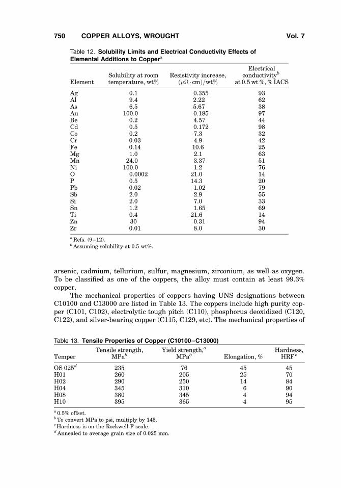
arsenic, cadmium, tellurium, sulfur, magnesium, zirconium, as well as oxygen.To be classified as one of the coppers, the alloy must contain at least 99.3%copper.
The mechanical properties of coppers having UNS designations betweenC10100 and C13000 are listed in Table 13. The coppers include high purity cop-per (C101, C102), electrolytic tough pitch (C110), phosphorus deoxidized (C120,C122), and silver-bearing copper (C115, C129, etc). The mechanical properties of
Table 12. Solubility Limits and Electrical Conductivity Effects ofElemental Additions to Coppera
ElementSolubility at roomtemperature, wt%
Resistivity increase,ð�� � cmÞ=wt%
Electricalconductivityb
at 0.5 wt%,% IACS
Ag 0.1 0.355 93Al 9.4 2.22 62As 6.5 5.67 38Au 100.0 0.185 97Be 0.2 4.57 44Cd 0.5 0.172 98Co 0.2 7.3 32Cr 0.03 4.9 42Fe 0.14 10.6 25Mg 1.0 2.1 63Mn 24.0 3.37 51Ni 100.0 1.2 76O 0.0002 21.0 14P 0.5 14.3 20Pb 0.02 1.02 79Sb 2.0 2.9 55Si 2.0 7.0 33Sn 1.2 1.65 69Ti 0.4 21.6 14Zn 30 0.31 94Zr 0.01 8.0 30
aRefs. (9–12).bAssuming solubility at 0.5 wt%.
Table 13. Tensile Properties of Copper (C10100–C13000)
TemperTensile strength,
MPabYield strength,a
MPab Elongation, %Hardness,
HRF c
OS 025d 235 76 45 45H01 260 205 25 70H02 290 250 14 84H04 345 310 6 90H08 380 345 4 94H10 395 365 4 95
a 0.5% offset.bTo convert MPa to psi, multiply by 145.cHardness is on the Rockwell-F scale.dAnnealed to average grain size of 0.025 mm.
750 COPPER ALLOYS, WROUGHT Vol. 7

these alloys are essentially the same. Other coppers, C142 through C157, offerhigher strength at usually lower conductivity. The mechanical properties ofalloys within the latter range are listed in Table 14.
Excellent resistance to saltwater corrosion and biofouling are notable attri-butes of copper and its dilute alloys. High resistance to atmospheric corrosionand stress corrosion cracking, combined with high conductivity, favor use inelectrical–electronic applications.
7.2. C101 and C102. The oxygen-free coppers, C10100 and C10200, aremanufactured by melting prime quality, electrolytically produced cathode copperunder reducing conditions designed to restrict oxygen content to below 0.0005%(C101) and 0.001% (C102). C101 has a minimum copper content, which may alsoinclude a trace of silver, of 99.99%. Oxygen-free copper is immune to hydrogenembrittlement, and provides low outgassing tendency, along with very high(101% IACS min) conductivity at 208C for annealed material.
7.3. C110. The most common commercial purity copper is C110. Theprincipal difference between C110 and C102 is oxygen content, which is deliber-ately controlled at 0.04% in C110 to eliminate many impurities that are deleter-ious to conductivity. Oxygen is present as cuprous oxide particles, which do notsignificantly affect strength and ductility, but C110 is susceptible to hydrogenembrittlement. The properties of C110 are adequate for most applications andthis alloy is less costly than higher purity copper.
7.4. Deoxidized Copper. Cuprous oxide can be readily removed fromcopper by small additions of phosphorus, calcium, and magnesium. Phosphorusis the most common deoxidizing element. Most phosphorus-deoxidized copperscontain residual phosphorus in concentrations of 0.01–0.04%. The most commonalloy in this family is C122, containing 0.015–0.040% phosphorus. Because ofresidual dissolved phosphorus, the minimum electrical conductivity of C122 is85% IACS, versus 100% IACS for C110. Applications involving brazing and weld-ing in hydrogen-rich atmospheres are important uses for deoxidized copperwhere embrittlement by hydrogen has to be avoided.
7.5. Specialty Coppers. Additions are made to copper to satisfy specificneeds. Tellurium at a nominal 0.5 wt% addition, sulfur at 0.35 wt%, and lead at1 wt% enhance machinability. These alloys are identified as C145, C147, and
Table 14. Tensile Properties of Dilute Alloy Coppers (C14300–C15720)
Alloy TemperTensile strength,
MPaa0.2% Yield
strength, MPaaElongation,% 50 mm
C14300 H04 310 275 14C14500b
C14700b H04 330 304c 20C15000 TH04d 445 411c 18C15100 H04 400 386 4C15500 H04 425 394 5C15720b 061 485 380 13
aTo convert MPa to psi, multiply by 145.bRod of 25 mm diameter.c0.5% offset for rod products.dSolution treated at 9508C, cold worked 90%, aged 1 h at 4508C.
Vol. 7 COPPER ALLOYS, WROUGHT 751

C187, respectively. The solubility limit for each element is <0.001%, so that theexcess is present as second-phase particles that assist in fracture of chips andlubrication during machining.
Additions of 0.1 wt% cadmium to phosphorus deoxidized copper (C143),0.05–0.2 wt% zirconium to copper (C150, C151), or Mg, Ag and P to copper(C155) significantly enhance softening resistance while maintaining high(85–95% IACS) conductivity. Because of environmental concerns, however,cadmium-containing alloys are being replaced by others that meet product andmanufacturing requirements.
Extremely high softening resistance is available in alloy C15720 throughdispersion strengthening by aluminum oxide. This alloy has been used success-fully as a welding rod material and in other specific applications that can bear itscost.
7.6. High Copper Alloys. The high copper alloys contain a minimum of96 wt% copper; most contain about 98.5 wt%. These alloys are found within theUNS classification of C162 to C199. As a group, they offer higher strength andbetter softening resistance than the specialty coppers. Like the coppers, thehigh copper alloys have excellent resistance to general and stress corrosioncracking. However, the high copper alloys have lower electrical conductivitiesthan the coppers, they are more expensive, and special processing may berequired to incorporate dispersoids or precipitates for optimal effectiveness.Nominal electrical conductivities and tensile properties of selected high coppersin hard rolled temper are summarized in Table 15.
7.7. Cadmium Copper (C162). Containing 1 wt% Cd, C162 has beenused for many years in electrical connectors because of its excellent (90%
Table 15. Conductivity and H04 (Hard) Temper Tensile Properties
UNS
Electricalconductivity,
% IACSTensile strength,
MPaa0.2% Yield
strength, MPaaElongation in50 mm, %
High copper alloysC16200 90 414 310 5C182b 80 460 405 14C19000 60 579 531 3C19200 65 448 414 7C19400 65 462 434 4C19500 50 593 572 2C19700 80 448 414 7
Cu—Zn brass alloysC210 56 (5% Zn) 379 365 5C220 44 (10% Zn) 428 400 4C230 37 (15% Zn) 469 421 7C240 32 (20% Zn) 496 421 4C260 28 (30% Zn) 524 496 10C353 26 (34% Zn, 2% Pb) 503 462 12C360c 26 (35% Zn, 3% Pb) 386 310 20
aTo convert MPa to psi, multiply by 145.bTH04 Temper material.cH02 Temper material.
752 COPPER ALLOYS, WROUGHT Vol. 7

IACS) electrical conductivity and formability. Much of the cadmium is in solution;the remainder is dispersed as Cu2Cd particles. Unique arc quenching ability,which reduces the surface degradation from electric-arc erosion during switch-ing, is characteristic of this alloy. However, environmental concern because ofcadmium ’s toxicity has all but eliminated its use, thus restricting its availability.
7.8. C190 to C197. The C190 to C197 alloys constitute a series of com-mercially useful copper alloys containing low levels of phosphorus; some containNi (C190–C191) and some contain Fe (C192–C197). They are relatively inexpen-sive and offer excellent combinations of strength, ductility, conductivity, andmoderate softening resistance. As a group, these alloys are readily processedto provide a uniform array of iron and iron or nickel phosphide dispersoids forhardening and grain size control. Offering electrical conductivities of 50–80%IACS, they find extensive use in electronic products as leadframes and in electri-cal connectors. C194 (nominally, Cu–2.4 Fe–0.04 P–0.1 Zn) has the distinctionof being the copper alloy that during the early 1970s replaced ASTM F30 (42 Ni—Fe alloy) as the dominant leadframe material in the electronics industry. Ofincreasing importance is the higher capacity for these alloys to dissipate heatfrom semiconductor packages and thus prolong integrated circuit (IC) life. Alsoof importance are their nonmagnetic properties permitting high clock speeds forIC devices (see INTEGRATED CIRCUITS; SEMICONDUCTOR TECHNOLOGY).
7.9. Copper–Zinc Brasses. copper–zinc alloys have been the mostwidely used copper alloys during the 1990s. It is no accident that the wordbrass is included in the name of many copper alloy manufacturers. The manufac-ture of brass buttons and other brass artifacts was the principal reason for theestablishment of the U.S. copper alloy industry in Connecticut during the 1800s.
Brass alloys fall within the designations C205 to C280 and cover theentire solid solution range of up to 35 wt% zinc in the Cu�Zn alloy system.Zinc, traditionally less expensive than copper, does not too greatly impairconductivity and ductility as it solution hardens copper.
Brass alloys are highly formable, either hot or cold, and provide moderatestrength and conductivity. Moreover, the alloys have a pleasing yellow ‘‘brass’’color at zinc levels >20 wt%. The material is amenable to polishing, buffing, plat-ing, and soldering. By far, the best known and most used composition is the30 wt% zinc alloy, Cartridge Brass. Door knobs and bullet cartridges are thebest known applications and illustrate the material’s excellent formability andgeneral utility. Properties of representative brass alloys in the hard temperare also summarized in Table 15.
The series of brasses, C312 to C385, contain from 0.25–5.0 wt% lead for thepurpose of improving machinability. C360, having the composition Cu–35.4 Zn–3.1 Pb, has become the industry standard for machinability performance. It isgiven the descriptive name of free-machining brass and a machinability ratingvalue defined as 100 (Table 10).
Brasses are susceptible to dezincification in aqueous solutions when theycontain >15wt% zinc. Stress corrosion cracking susceptibility is also significant>15 wt% zinc. Over the years, other elements have been added to the Cu—Znbase alloys to improve corrosion resistance. For example, a small addition ofarsenic, antimony, phosphorus, or tin helps prevent dezincification to makebrasses more useful in tubing applications.
Vol. 7 COPPER ALLOYS, WROUGHT 753

7.10. Tin Brasses. The tin brass series of alloys consists of variouscopper–(2.5–35 wt%) zinc alloys to which up to �4 wt% tin has been added.These are solid solution alloys that have their own classification as the C40000series of alloys. Tin provides better general corrosion resistance and strengthwithout greatly reducing electrical conductivity. As with all the brasses, thesealloys are strengthened by cold work and are available in a wide range oftempers. These alloys offer the combined strength, formability, and corrosionresistance required by their principal applications, namely, fuse clips, weatherstripping, electrical connectors, heat exchanger tubing, and ferrules. Severaltin brasses have lead additions to enhance machinability. For example, thehigh leaded Naval Brass C485, containing Cu–37 Zn–0.7, Sn–1.8 Pb, has amachinability rating of 78.
Table 16 illustrates the property enhancements and tradeoffs seen when tinis added to a copper–zinc brass base composition. The most commonly usedalloys for electrical connectors are the Cu–10 Zn�Sn brasses, such as C411,C422, and C425. These tin brasses offer improved corrosion and stress relaxationresistance relative to the base Cu�Zn alloy.
Admiralty Brass and Naval Brass are 30 and 40% zinc alloys, respectively,to which a 1% tin addition has been added. Resistance to dezincification ofCu�Zn alloys is increased by tin additions. Therefore, these alloys are importantfor their corrosion resistance in condenser tube applications. In these, as well asthe other higher zinc compositions, it is common to use other alloying additives toenhance corrosion resistance. In particular, a small amount (0.02–0.10 wt%) ofarsenic (C443), antimony (C444), or phosphorus (C445) is added to control dezin-cification. When any of these elements are used, the alloy is referred to as being‘‘inhibited.’’ For good stress corrosion resistance, it is recommended that thesealloys be used in the fully annealed condition or in the cold worked plus stressrelief annealed condition.
7.11. Tin Bronzes. Tin bronzes may be the most familiar of copperalloys with roots going back into ancient times. Whereas bronze is still usedfor statuary, these alloys are found in many modern applications, such as elec-trical connectors, bearings, bellows, and diaphragms. The wrought tin bronzesare also called phosphor bronzes because 0.03–0.35 wt% phosphorus is com-monly added for deoxidation and improved melt fluidity during casting.
Table 16. Conductivity and Wrought Tensile Strength of Tin–Brasses Showing theHardening Effect of Tin Additions
Electricalconductivity, %
IACS
Tensile strength, MPaa
UNS Zinc, wt% Tin, wt% H04 Temper H08 Temper
C411 10 0.5 32 448 552C425 10 2.0 28 524 634C220 10 44 428 524C443 30 1.0 25 607C260 30 28 524 690
aTo convert MPa to psi, multiply by 145.
754 COPPER ALLOYS, WROUGHT Vol. 7

The several wrought alloys of commercial importance span the range of1.0–10 wt% tin and are mostly used in work hardened tempers. These alloysare single phase and offer excellent cold working and forming characteristics.Strength, corrosion resistance, and stress relaxation resistance increase withtin content. The tin–phosphorus alloys are highly resistant to stress corrosioncracking and have good resistance to impingement corrosion attack. Unfortu-nately, conductivity decreases, cost increases (tin has been historically morecostly than copper), and the capability of being hot processed is impaired astin level is increased. Only compositions up to �4.5 wt% tin show good hot pro-cessing characteristics. The richer compositions are cast in thinner cross-sectionsthat can be cold rolled directly. Several cycles of working and annealing areemployed to homogenize the cast microstructure.
One of the most highly used specialty tin bronzes is C544, containing Cu–4Sn–4 Zn–4 Pb. Zinc provides increased strength to this tin bronze, whereas thelead addition provides good machinability (machinability rating of 80)andenhances wear resistance. C544 is used in many applications where these twolatter properties are of the utmost benefit, namely, bearings, bushings, gears,pinions, washers, and valve parts. Table 17 indicates the range of propertiesavailable for the commonly used phosphor bronzes.
7.12. Aluminum Bronzes. Aluminum bronze alloys comprise a series ofalloys (C606 to C644) based on the copper–aluminum (2–15 wt%) binary system,to which iron, nickel, and/or manganese are added to increase strength. Themechanical properties of commercially important alloys in this group are listedin Table 18.
Aluminum bronze alloys are used for their combined good strength, wear,and corrosion-resistance properties where high electrical and thermal conductiv-ity are not required. Corrosion resistance results from the formation of an adher-ent aluminum oxide that protects the surface from further oxidation. Mechanicaldamage to the surface is readily healed by the redevelopment of this oxide. Thealuminum bronzes are resistant to nonoxidizing mineral acids such as sulfuric orhydrochloric acids, but are not resistant to oxidizing acids such as nitric acid.However, these alloys must be properly heat treated to be resistant to dealloyingand general corrosion.
The aluminum oxide surface layer that provides wear and corrosion resis-tance is not without drawbacks. This adherent film is difficult to remove during
Table 17. Conductivity and Wrought Tensile Strength of Tin Bronze Alloys
Electricalconductivity, %
IACS
Tensile strength, MPaa
UNS Tin, wt% H04 Temper H08 Temper
C505 1.0 48 441 552C511 4.0 20 545 696C510 5.0 15 572 738C521 8.0 13 634 800C524 10.0 11 690 882C544 4.0b 19 545 703
aTo convert MPa to psi, multiply by 145.bAlso contain 4 wt % each of zinc and lead.
Vol. 7 COPPER ALLOYS, WROUGHT 755

industrial cleaning of the alloys. Cleaning techniques have been developed thatfragment the tightly adherent aluminum oxide film before removing it by thenonoxidizing mineral acids commonly used in brass mill processing. Further-more, excessive tool wear in stamping and shearing equipment is caused bythe presence of this film. Soldering and brazing are also made difficult by thisoxide film.
Two single-phase, binary alloys are used commercially: C606, containing5 wt% Al, and C610, 8 wt% Al. Both alloys have a golden color and are used inrod or wire applications, such as for bolts, pump parts, and shafts. Most of theavailable aluminum bronzes contain additional alloy elements, however. Forexample, C608 is a commonly specified condenser or heat exchanger tube alloythat is essentially 5% aluminum to which 0.02–0.35 wt% arsenic has beenadded to improve corrosion resistance. Alloy C613, having 7 Al–2.5 Fe also hasa 0.3 wt% tin addition for improved resistance to stress corrosion.
Most of the aluminum bronzes contain substantial iron, nickel, or manga-nese additions. These alloying elements increase strength by forming secondphases during heat treatment. Iron, the most commonly added element inthese bronzes, separates as an iron-rich particle that controls grain size whileit enhances strength. Nickel also reacts with aluminum to form NiAl precipitatesduring heat treatment with the same result as the iron addition.
Several Cu—Al—Si alloys have commercial importance. For example, C636containing 3.5 Al—1.0 Si, is a rod and wire alloy that is processed to around590 MPa 85,000 (psi) tensile strength. C638, containing 2.8 Al–1.8 Si–0.4 Co,is a strip product that owes its good strength and formability to dispersionstrengthening and a very fine grain size that results from precipitation of cobaltsilicide particles. The latter alloy attains tensile strengths of 566 MPa (82,000 psi)and 883 MPa (128,000 psi) in the annealed and spring rolled (H08) tempers,respectively.
7.13. Silicon Bronzes. Silicon bronzes have long been available for usein electrical connectors, heat exchanger tubes, and marine and pole line hard-ware because of their high solution hardened strength and resistance to generaland stress corrosion. As a group, these alloys also have excellent hot and coldformability. Unlike the aluminum bronzes, the silicon bronzes have moderatelygood soldering and brazing characteristics. Their compositions are limited tobelow 4.0 wt% silicon because above this level, an extremely brittle phase
Table 18. Conductivity and H04 (Hard) Temper Tensile Properties of AluminumBronze Alloys
Constituents, wt% Electricalconductivity, %
IACS
Tensilestrength,MPaa
0.2% Yieldstrength,MPaa
Elongation in50 mm, %UNS Al Fe Ni
C614 7 2.5 14 586 400 35C615 8 2 13 862 620 5C625 13 4.5 10 690 379 1C630b 10 3.0 5 7 814 517 15
aTo convert MPa to psi, multiply by 145.bAlso contains 1.5 wt% manganese.
756 COPPER ALLOYS, WROUGHT Vol. 7
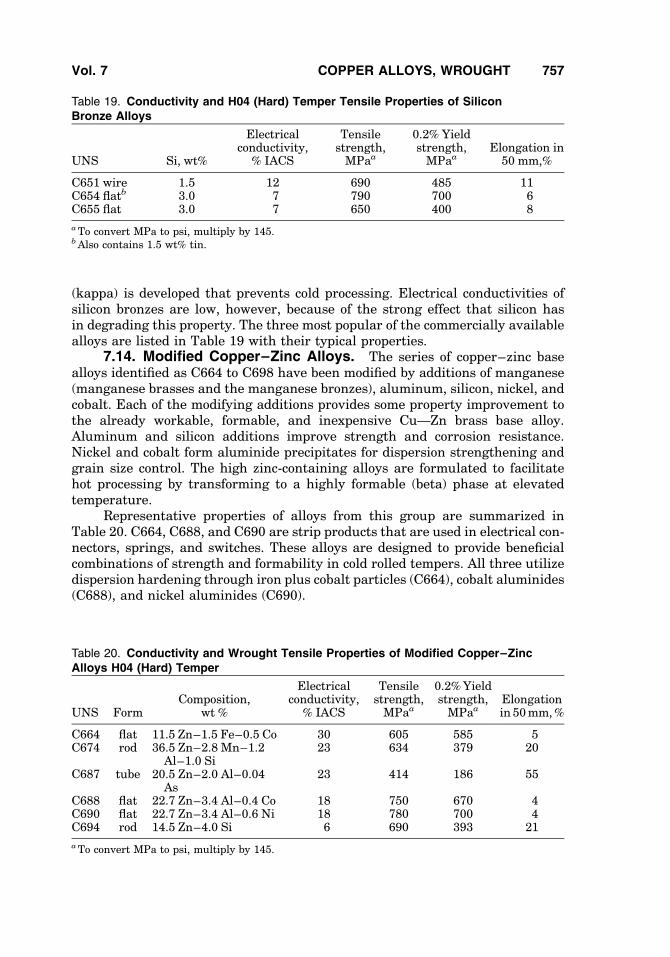
(kappa) is developed that prevents cold processing. Electrical conductivities ofsilicon bronzes are low, however, because of the strong effect that silicon hasin degrading this property. The three most popular of the commercially availablealloys are listed in Table 19 with their typical properties.
7.14. Modified Copper–Zinc Alloys. The series of copper–zinc basealloys identified as C664 to C698 have been modified by additions of manganese(manganese brasses and the manganese bronzes), aluminum, silicon, nickel, andcobalt. Each of the modifying additions provides some property improvement tothe already workable, formable, and inexpensive Cu—Zn brass base alloy.Aluminum and silicon additions improve strength and corrosion resistance.Nickel and cobalt form aluminide precipitates for dispersion strengthening andgrain size control. The high zinc-containing alloys are formulated to facilitatehot processing by transforming to a highly formable (beta) phase at elevatedtemperature.
Representative properties of alloys from this group are summarized inTable 20. C664, C688, and C690 are strip products that are used in electrical con-nectors, springs, and switches. These alloys are designed to provide beneficialcombinations of strength and formability in cold rolled tempers. All three utilizedispersion hardening through iron plus cobalt particles (C664), cobalt aluminides(C688), and nickel aluminides (C690).
Table 19. Conductivity and H04 (Hard) Temper Tensile Properties of SiliconBronze Alloys
UNS Si, wt%
Electricalconductivity,
% IACS
Tensilestrength,MPaa
0.2% Yieldstrength,MPaa
Elongation in50 mm,%
C651 wire 1.5 12 690 485 11C654 flatb 3.0 7 790 700 6C655 flat 3.0 7 650 400 8
aTo convert MPa to psi, multiply by 145.bAlso contains 1.5 wt% tin.
Table 20. Conductivity and Wrought Tensile Properties of Modified Copper–ZincAlloys H04 (Hard) Temper
UNS FormComposition,
wt %
Electricalconductivity,
% IACS
Tensilestrength,MPaa
0.2%Yieldstrength,MPaa
Elongationin 50mm,%
C664 flat 11.5 Zn–1.5 Fe–0.5 Co 30 605 585 5C674 rod 36.5 Zn–2.8 Mn–1.2
Al–1.0 Si23 634 379 20
C687 tube 20.5 Zn–2.0 Al–0.04As
23 414 186 55
C688 flat 22.7 Zn–3.4 Al–0.4 Co 18 750 670 4C690 flat 22.7 Zn–3.4 Al–0.6 Ni 18 780 700 4C694 rod 14.5 Zn–4.0 Si 6 690 393 21
aTo convert MPa to psi, multiply by 145.
Vol. 7 COPPER ALLOYS, WROUGHT 757

C674 and C694 are commonly used in rod and wire forms. These alloys areused in valve stems, shafts, bushings, and gears. Dispersoids of second phasesthat come about from beta-phase decomposition products account for their higherstrength. C687, inhibited by the arsenic addition, is primarily a tube alloy that isused in condensers, evaporators, heat exchangers, and ferrules.
7.15. Copper–Nickels. The copper–nickel alloy system is essentiallysingle phase across its entire range. Alloys made from this system are easily fab-ricated by casting, forming, and welding. They are noted for excellent tarnishingand corrosion resistance. Commercial copper alloys extend from 5 to 40 wt%nickel.
Iron is added in small (usually 0.4–2.3 wt%) amounts to increase strength.More importantly, iron additions also enhance corrosion resistance, especiallywhen precautions are taken to retain the iron in solution. Precipitation of theiron–nickel-rich phase does not result in strengthening and can cause degrada-tion of corrosion resistance (49). A small (up to 1.0 wt%) amount of manganese isusually added to react with and remove both sulfur and oxygen from the melt.These copper alloys are most commonly applied where corrosion resistance isparamount, as in condenser tube or heat exchangers.
The common cupronickels are C704, which has 5 Ni–1.5 Fe; C706, 10 Ni–1.4 Fe; C710, 20 Ni; and C715, 30 Ni–0.7 Fe. Mechanical properties of thesealloys are summarized in Table 21. The best resistance to aqueous corrosion isavailable from C715 containing 30 wt% nickel. Both C715 and the lower costC706 are suited for condenser and heat exchanger tubes in power plants. Thisgroup of alloys is also highly resistant to stress corrosion and impingement cor-rosion.
C725, a 9 wt% nickel alloy that is further strengthened by 2 wt% tin, is usedin electrical connectors and bellows. Properties are summarized in Table 21. Thealloy has good resistance to stress relaxation at room and moderately elevatedtemperatures, which accounts for its use in electrical connectors and electricalcircuit wire wrap pins.
Environmental factors must be considered when specifying copper–nickelalloys. The higher nickel compositions are less resistant to sulfides in seawaterapplications, for example. C713, containing 25 wt% nickel, is extensively usedin U.S. coinage because of its good tarnish resistance. C722, containing Cu–17Ni–0.8 Fe–0.5 Cr, is intended as a tube alloy having improved resistance
Table 21. Conductivity and H04 (Hard) Temper Tensile Properties ofCupro–Nickel Alloys
UNS Alloy, wt %
Electricalconductivity, %
IACS
Tensilestrength,MPaa
0.2% Yieldstrength,MPaa
Elongation in50 mm, %
C704 5.5 Ni–1.5 Fe 14.0 440 435 5C706 10 Ni–1.4 Fe 9.0 518 500 5C710 20 Ni 6.5 518 500 5C715 30 Ni–0.5 Fe 4.6 580 545 3C725 9 Ni–2 Sn 11.0 570 555 3
aTo convert MPa to psi, multiply by 145.
758 COPPER ALLOYS, WROUGHT Vol. 7

to impingement corrosion in flowing water in condenser or heat exchangerapplications.
7.16. Nickel–Silvers. Nickel–silver alloys, once called German silver,are a series of solid solution Cu–Ni–Zn alloys, the compositions of which encom-pass the ranges of 3–30 wt% Zn and 4–25 wt% Ni. This family of alloys fallswithin the UNS designation numbers C731 to C770. Leaded nickel–silversthat contain from 1.0 to 3.5 wt% lead for improved machining characteristicsare designated as C782 to C799.
Nickel–silver alloys are not readily hot worked but have excellent cold fab-ricating characteristics. Because of the high nickel and zinc contents, thesealloys exhibit good resistance to corrosion, good strength, and usually adequateformability, but have low electrical conductivity. Wire and strip are the dominantforms used for hardware, rivets, nameplates, hollowware, and optical parts.Table 22 lists common nickel–silvers and compares electrical conductivitiesand tensile strengths. Because of high nickel contents, these alloys are highlyresistant to dezincification in spite of the high zinc content. Good resistance tocorrosion in both fresh and seawater is another attribute.
Of the several leaded nickel–silvers, C782 (Cu–23Zn–10Ni–2Pb) is one ofthe most commonly used. This alloy is not hot processable and has limited coldprocessing capacity. It is usually available as strip for application as keystock,watch parts, and plates because of its excellent machinability, hardness andcorrosion resistance.
7.17. Precipitation Hardening Alloys. Copper alloys that can be pre-cipitation hardened to high strength are limited in number. In addition to themetallurgical requirement that the solubility of the added element(s) decreaseswith decreasing temperature, the precipitated phase that forms during agingmust be distributed finely and have characteristics that act to resist plasticdeformation.
Commercial precipitation hardening copper alloys are based on beryllium,chromium, titanium, and nickel, the latter in combination with silicon or tin. Theprincipal attributes of these alloys are high strength in association with ade-quate formability. Electrical conductivity varies according to alloy and rangesfrom �20–80% IACS.
Usually, the aging treatment is done by the strip manufacturer, to pro-duce ‘‘mill hardened’’ strip. The resulting strip properties are a practical compro-mise between good formability and less-than-peak strength. The advantage of
Table 22. Conductivity and Hard Temper Tensile Properties of Cu—Ni—Zn Alloys
UNS Nickel, wt % Zinc, wt %
Electricalconductivity,
% IACS
Tensilestrength,MPaa
0.2% Yieldstrength,
MPa
Elongationin
50 mm, %
C745 10 25 9 590 515 4C752 18 17 6 585 510 3C754 15 20 7 585 515 3C757 12 23 8 585 515 4C770 18 27 6 585 505 4
aTo convert MPa to psi, multiply by 145.
Vol. 7 COPPER ALLOYS, WROUGHT 759

these tempers is that the fabricator does not need to heat treat the strip, elimi-nating the need for post-form cleaning and the possibility of part distortion dur-ing the anneal. The highest strength can, however, be achieved by the fabricatorperforming the precipitation hardening thermal treatment following fabricationof parts from solution treated–cold rolled temper strip. This allows the fabricatorto take advantage of the superior formability to make the most geometricallydemanding parts and achieve high strength by aging after part fabrication.
7.18. C170 to C175 (Beryllium Copper). The addition of beryllium tocopper results in a significant age hardening response, making these alloys oneof the few nonferrous materials that can reach 1400-MPa (200,000 psi) tensilestrength (7). These alloys are more precisely ternary alloys. Additions of cobaltor nickel control grain size through the formation of coarse beryllides that pingrain boundaries and promote the hardening precipitation reaction.
Table 23 illustrates yield strength–bend formability trade-offs associatedwith making parts from a mill hardened temper (TM02) versus forming rolledtemper strip (H02) and then aging to produce a TH02 temper product. Partsthat require the same formability can be made using both the rolled temperand mill hardened material, but it is possible to achieve higher strength byaging after forming. However, aging after forming can introduce dimensionalchanges that accompany the hardening reaction in beryllium coppers. Moreover,the parts must be chemically cleaned with aggressive reagents to remove beryl-lium oxide formed during the thermal treatment. For these reasons, mill har-dened strip represents the majority of the beryllium copper that is used.
The trade-off between conductivity and formability, at comparablestrength, is also shown in Table 23. More dilute compositions (C17410 andC1751) provide higher conductivity in the mill hardened condition, but at a sacri-fice in formability relative to mill hardened C172.
Toxicity concerns regarding beryllium result principally from possible con-sequences from inhaling its oxide. Any operation that produces airborne particlesor dust of the oxide must be carried out using proper precautions to personnel.
7.19. C180 to C182 (Chromium–Copper). Chromium–copper alloyshavewidespreaduse in those applications requiring good formability, conductivity,
Table 23. Properties of Beryllium Copper Alloys
Conductivity, %IACSb
Yield strength,MPac
Formability,MBR/ta
UNS Temper GW BW
C172 H02 15 586 0.5 1TH02d 20 1207 >5 >5TM02 18 758 0.5 1
C17410 HT 45 758 1.2 5.0C17460 HT 50 792 1.5 1.5C1751 TH04 50 758 2 2
aFor 908 bend forming angle.bMinimum values given.cTo convert MPa to psi, multiply by 145.dH02 temperþ aged at 3158C for 2 h.
760 COPPER ALLOYS, WROUGHT Vol. 7

stress relaxation resistance and strength. For example, both welding electrodetips and electrical connectors require moderate strength and relatively high con-ductivity, but the former also requires good softening resistance, whereas the lat-ter also requires good formability. As much as 0.65 wt% chromium can bedissolved in copper to produce a uniform array of pure chromium precipitatesduring the age hardening treatment. The low room temperature solubility ofchromium (<0.03%) ensures good (usually �85% IACS) conductivity after thesubsequent age hardening heat treatment. Moreover, compositions above themaximum solubility level are commercially made in order to take advantage ofthe dispersion of coarser chromium particles that are useful for control of grainsize. Typical properties of chromium–copper alloys in age hardened temper aresummarized in Table 24.
7.20. Cu–Ni–Si Alloys. This commercially important alloy family isprecipitation hardened through the formation of Ni2Si for optimum combinationsof strength, conductivity, and formability. The composition and processing ofC7025 also results in high temperature resistance to both stress relaxationand softening, required for part manufacturing and service of elevated tempera-ture connectors. These alloys are notable also for good general corrosion andstress corrosion resistance that is equivalent to the highly resistant phosphorbronzes. High strength combined with moderate conductivity available fromthe alloy is important for applications where ohmic (I2R) heating from high elec-trical currents are possible.
Cu—Ni—Si alloys are also available in more dilute versions such asC19010. Higher conductivity but lower strength is available from the latteralloy. Table 25 compares mechanical properties of the mill hardened conditionof these alloys.
7.21. C726 to C729. Very high strength, nearly equal to that availablefrom beryllium–copper, is possible with precipitation hardened Cu—Ni—Snalloys. These alloys, referred to in the literature as spinodal alloys are hardenedby a precipitation reaction known as spinodal decomposition. They encompass arange of compositions that includes Cu–7.5 Ni–5 Sn (C7265), Cu–9 Ni–6 Sn(C727) and Cu–15 Ni–8 Sn (C729). More dilute compositions such as Cu–4Ni–4 Sn (C726) do not precipitation harden appreciably, as do C727 and C729.The latter two alloys are not easily hot worked and are usually made by stripcasting followed directly by cold working, or by consolidation of alloy powder.
Table 24. Conductivity and Age Hardened Tensile Properties ofChromium–Copper Alloys
UNSComposition,
wt %
Electricalconductivity,
% IACS
Tensilestrength,MPaa
0.2% Yieldstrength,MPaa
Elongationin
50 mm, %
C18080 0.5 Cr–0.1 Ag–0.1Fe–0.06Ti–0.03Si
80 515 480 9
C181 0.8 Cr–0.15 Zr–0.04 Mg 80 496 455 10C18135 0.4 Cr–0.4 Cd 92 469 421 12C182 0.9 Cr 80 460 405 14
aTo convert MPa to psi, multiply by 145.
Vol. 7 COPPER ALLOYS, WROUGHT 761

Like beryllium copper, C729 is available in the rolled temper condition, forsubsequent aging after forming, or in the mill hardened condition. Typical prop-erties of these alloys are shown in Table 25. In addition, these alloys exhibit nota-bly excellent resistance to stress relaxation at high application temperatures, eg,2008C, and in this respect outperform beryllium–copper. However, the 8% IACSelectrical conductivity of the strongest Cu�Ni�Sn composition (C729) is lowerthan that of C172.
8. Economic Aspects
One of the factors affecting the relative pricing of commercial copper alloys ismetal value. The metal value of copper was around $1.65/kg ($0.75/lb) at theend of 2002. Other factors affecting costs include metal value of the constituentalloy elements, order quantities, the supplier, and specified dimensional toler-ances. Oxygen-free copper, C102, is sold as a premium product relative to copper.Brass, eg, C260, is less costly than copper because zinc is historically lower pricedthan copper. Tin-containing phosphor bronzes, such as C510, and nickel contain-ing alloys such as the 700-series are more costly than brass and copper because ofhigher tin and nickel metal cost, respectively.
9. Applications
Alloy selection for a particular application generally involves consideration of acombination of physical and mechanical properties as well as cost. Heat exchan-gers, including automobile radiators and domestic heating systems, are primeexamples. Alloys used for such applications require not only good corrosion resis-tance and reasonable thermal conductivity, but also the capabilities of beingformed into a variety of shapes and joined easily by soldering or brazing. C110and C122 coppers are therefore widely used in such applications. C260 brass has
Table 25. Properties of Precipitation Hardened Cu—Ni—Base Alloys
UNSComposition,
wt % Temper
Cond.,%
IACS
Tensilestrength,MPaa
0.2%Yield
strength,MPaa
Elongationin
50 mm,%
C180 2.5 Ni–0.6 Si–0.4 Cr H50 48 690 525 12C19010 1.3 Ni–0.25 Si–0.03P Extra
Hard60 551 517 6
C7025 3 Ni–0.65 Si–0.15 Mg TM00 40 690 530 12TM03 35 785 735 7
C7026 2 Ni–0.5 Si TM04 50 670 620 6C7265 7.5 Ni–5 Sn TH04 1015 945 4
TM04 15 860 755 12C729 15 Ni–8 Sn TH04 1240 1100 3
TM04 8 860 790 15
aTo convert MPa to psi, multiply by 145.
762 COPPER ALLOYS, WROUGHT Vol. 7

also been used extensively in automobile radiators because of the good formabil-ity it possesses for manufacture of headers and because of its strength. Copper–nickel alloys such as C706 and C715 find application in condensers used in powerutilities and desalination units because of their good corrosion resistance andreasonable conductivity relative to alternative materials.
Electrical interconnections that range from home wall receptacles to minia-ture connectors used in electronic products all require good formability and otherproperties specific to their application. Automotive connectors are frequentlysituated in the harsh environment of the engine compartment, where resistanceto stress relaxation is needed to provide stable contact force for reliable perfor-mance. Alloys like the beryllium coppers and C7025 are supplanting C260 brassand the phosphor bronzes in such elevated temperature applications. Intercon-nection systems, which carry large currents, require high electrical conductivityto minimize ohmic (I2R) heating. Unacceptable loss in contact force due to stressrelaxation can result in open-circuit failure of the connector if the operating tem-perature is too high for the alloy being used. The high copper alloys are thereforeto be favored in such applications, provided that they also have adequate stressrelaxation resistance. Alloys C151, C18080, C182, and C194 can more easilymeet these property requirements. Computers, consumer electronics and tele-communications systems require connectors which carry only small, signallevel, currents. The miniaturization trend in these applications, however, resultsin a requirement for copper alloys with yield strength >100 ksi, conductivity>45% IACS and good formability; eg, C7025 and C17460.
Strength, thermal conductivity and formability account for selection of par-ticular alloys for use as leadframes in plastic encapsulated devices. Leads havinghigh strength are needed to ensure against damage to the electronic packageduring handling before and during assembly to circuit boards. This requirementis particularly critical for high lead count packages where the leadframe materialis thin (�0.15 mm) and leads are extremely narrow (0.30 mm). The leadframealso provides a path for heat to be dissipated from the operating integrated cir-cuit (chip) to prolong its service lifetime. Alloys that provide high strength near690 MPa (100,000 psi) yield strength combined with high thermal conductivity(at least 175 W/(m�K), equivalent to around 40% IACS electrical conductivity)are preferred for such applications.
Other applications that take advantage of the high electrical and thermalconductivity of copper and its alloys include superconducting wires and RF/EMI shielding. Controlled electrical resistance is required for applications suchas resistance heating as in heated car seats.
An additional virtue of many copper alloys is the capacity for deep drawingsuch as cartridge cases and flexible bellows. C260 and C510 are well known fortheir drawability. Be–Cu that is drawn and then aged is used for bellows thathave excellent fatigue life.
Finally, coinage and architectural uses take advantage of the variety of dis-tinctive colors inherent to copper and its alloys, from red, through gold-yellowand silver-white, as well as tarnish and corrosion resistance. Among the alloysused are C713, a white-appearing alloy used in U.S. coinage; gold-appearing alu-minum–bronze (C6155) and brass (C260); and red-brown copper–tin bronze.Clad coinage having dissimilar copper alloys for the clad and core components
Vol. 7 COPPER ALLOYS, WROUGHT 763

have the further advantage of being difficult to counterfeit when used in vendingmachines. The worldwide trend has been to use coins to replace low denomina-tion paper bills because the useful lifetime of coins is much longer.
Finally, it is important to note that the ability to be plated or coated with awide range of materials including tin, solder, chromium, nickel, gold and palla-dium is an important attribute of copper alloys which contributes to their selec-tion for many applications. For example automotive connectors may be tin orsolder coated, whereas electronics connectors are nickel and gold plated with pal-ladium used also. Decorative brass hardware may receive a chromium coating forcosmetic purposes.
BIBLIOGRAPHY
‘‘Copper Alloys, Wrought’’ in ECT 1st ed., Vol. 4, pp. 431–458, by R. E. Ricksecker, ChaseBrass & Copper Co.; ‘‘Copper Alloys (Wrought)’’ in ECT 2nd ed., Vol. 6, pp. 181–244, byR. E. Ricksecker, Chase Brass & Copper Co.; in ECT 3rd ed., Vol. 7, pp. 1–68, by R. E.Ricksecker, Chase Brass & Copper Co., Inc.; in ECT 4th ed., pp. 429–473; by John F. Breedisand Ronald N. Caron, Olin Corporation; ‘‘Copper Alloys, Wrought Copper and WroughtCopper Alloys’’ in ECT (online), posting date: December 4, 2000, by John F. Breedis andRonald N. Caron, Olin Corporation.
CITED PUBLICATIONS
1. Standard Practice for Temper Designations for Copper and Copper Alloys—Wroughtand Cast, ASTM B 601–92, American Society for Testing and Materials, Philadel-phia, Pa., 1992.
2. ‘‘Alloy Phase Diagrams,’’ Vol. 3, Metals Handbook, 10th ed., ASM International,Materials Park, Ohio, 1992.
3. T. B. Massalski, ed., Binary Alloy Phase Diagrams, Vol. 1, ASM International, Mate-rials Park, Ohio, 1986.
4. M. M. Shea and N. S. Stoloff, Met. Trans. 5, 755 (1974).5. R. L. Fleischer, Acta Met. 11, 203 (1963).6. Standards Handbook, Part—Alloy Data Wrought Copper and Copper Alloy Mill Pro-
ducts, 8th ed., Copper Development Association, Greenwich, Conn., 1985.7. The Mechanical Properties of Copper–Beryllium Alloy Strip, ASTM STP 367, Amer-
ican Society for Testing and Materials, Philadelphia, Pa., 1964.8. Standard Test Method for Resistivity of Electrical Conductor Materials, ASTM B
193-87, American Society for Testing and Materials, Philadelphia, Pa., 1992.9. F. Pawlek and K. Reichel, Zeit. Metallk. 47, 347 (1956).
10. Y. T. Hsu and B. O’Reilly, J. Met. 29, 21 (1977).11. C. Drapier, Rev. Metal. 75, 699 (1978).12. J. W. Borough, Trans. Met. Soc. AIME 221, 1274 (1961).13. Forming and Forging, Vol. 14, Metals Handbook, ASM International, Materials Park,
Ohio, 1988, pp. 575–590, 809–824, 877–899.14. E. Shapiro and F. N. Mandigo, Forming Limit Analysis for Enhanced Fabrication,
INCRA Monograph X, The Metallurgy of Copper, INCRA, New York, 1983.15. K. Suzuki, K. Ueda, and M. Tsuji, Trans. Jpn. Inst. Met. 25, 716 (1984).16. D. V. Wilson, J. Inst. Met. 94, 84 (1966).
764 COPPER ALLOYS, WROUGHT Vol. 7

17. W. A. Backofen, Met. Trans. 4, 2679 (1973).18. K. Laue and H. Stenger, Extrusion: Processes, Machinery, Tooling, ASM, Materials
Park, Ohio, 1976.19. W. L. Finlay, Silver-Bearing Copper, Corinthian Edition, Copper Range Co., New
York, 1968.20. J. H. Mendenhall, Understanding Copper Alloys, Winchester Press, New York, 1977.21. A. Fox and E. O. Fuchs, J. Testing Eval. 6, 211 (1978).22. A. Fox, J. Testing Eval. 2, 32 (1974).23. Standard Methods for Stress Relaxation Tests for Materials and Structures, ASTM E
328-86, American Society for Testing and Materials, Philadelphia, Pa., 1992.24. Fatigue Crack Propagation, ASTM STP 415, American Society for Testing and Mate-
rials, Philadelphia, Pa., 1967.25. A. Fox, J. Mater. JMLSA 5, 273 (1970).26. C. E. Feltner and C. Laird, Acta Met. 15, 1621 (1967).27. J. P. Hickerson and R. W. Hertzberg, Met. Trans. 3, 179 (1972).28. P. O. Kettunen and U. F. Kocks, Acta Met. 20, 95 (1972).29. Fatigue of Copper Alloys, Vol. 19, Metals Handbook, Fatigue and Facture,
pp. 869–873.30. Lead Integrity, Method 2004, Standard 883C, Dept. of Defense, Washington, D.C.,
1977.31. Factors Affecting Lead Bend Fatigue in P-DIPS, D. Mahulikar and T. Hann, Micro-
electronics and Processing Engineers Conference, 1985.32. Corrosion, Vol. 13. Metals Handbook, 9th ed., ASM International, Materials Park,
Ohio, 1987.33. J. M. Popplewell and T. V. Gearing, Corrosion 31, 279 (1975).34. A. Sterling, A. Atrens, and I. O. Smith, Br. Corros. J. 25, 271 (1990).35. K. D. Efird, Corrosion 33, 3 (1977).36. R. H. Heidersbach and E. D. Verink, Corrosion 28, 397 (1972).37. Standard Test Methods for Use of Mattsson’s Solution of pH 7. 2 to Evaluate the
Stress Corrosion Cracking Susceptibility of Copper–Zinc Alloys, ASTM G 37-85,American Society for Testing and Materials, Philadelphia, Pa., 1992.
38. Standard Practice for Making and Using U-Bend Stress–Corrosion Test Specimens,ASTM G 30-84, American Society for Testing and Materials, Philadelphia, Pa., 1992.
39. S. Harper, V. A. Callcut, D. W. Townsend, and R. Eborall, J. Inst. Metals 90, 423(1961).
40. M. Koiwa, A. Yamanaka, A. Arita, and H. Numakura, Mater. Trans., Jpn. Inst.Metals 30, 991 (1989).
41. Standard Methods of Test for Hydrogen Embrittlement of Copper, ASTM B 577,American Society for Testing and Materials, Philadelphia, Pa., 1992.
42. Welding, Brazing, and Soldering, Vol. 6, Metals Handbook, 9th ed., ASM Interna-tional, Materials Park, Ohio, 1983.
43. Wetting Balance Solderability, Method 2022.2, Military Standard-883C, Dept. ofDefense, Washington, D.C., 1987.
44. Solderability, Method 2003.5, Military Standard –883C, Test Methods and Proce-dures for Microelectronics, Dept. of Defense, Washington, D.C., 1987.
45. S. P. Zarlingo and J. C. Fister, ‘‘Solderability Performance of Tin Coated Copper Stripfor Connector Components,’’ Proceedings, 41st Electronic Components and TechnologyConference, Atlanta, Ga., IEEE, 1991, p. 229.
46. Specification for Electrodeposited Coatings of Tin, ATM B 545-83, American Societyfor Testing and Materials, Philadelphia, Pa., 1992.
47. Specification for Electrodeposited Coatings of Tin –Lead Alloy (Solder Plate), ASTM B579-82, American Society for Testing and Materials, Philadelphia, Pa., 1992.
Vol. 7 COPPER ALLOYS, WROUGHT 765

48. Machining, Vol. 16, Metals Handbook, 9th ed., ASM International, Materials Park,Ohio, 1989, pp. 805–819.
49. E. W. Palmer and F. H. Wilson, J. Metal. 4, 55 (1952).
GENERAL REFERENCES
References 13,17–20 are good general references.Properties and Selection: Nonferrous Alloys and Special Purpose Materials, Vol. 2, Metals
Handbook, 10th ed., ASM International, Materials Park, Ohio, 1990, pp. 215–345.Materials Selection and Designs, Vol. 20, Metals Handbook, 10th ed., ASM International,
Materials Park, Ohio, 1997.Source Book on Copper and Copper Alloys, ASM International, Materials Park, Ohio,
1979.Mechanical Testing, Vol. 8, Metals Handbook, 9th ed., ASM International, Materials
Park, Ohio, 1985.Powder Metallurgy, Vol. 7,Metals Handbook, 9th ed., ASM International, Materials Park,
Ohio, 1984.Copper ’86 Copper Tomorrow, Conference Proceedings, Europa Metalli-LMI, Florence,
Italy, 1986.Copper ’90 Refining, Fabrication, Markets, Conference Proceedings, Vasteras, Sweden,
Institute of Metals, London, 1990.Application Data Sheet—Standard Designations for Wrought and Cast Copper and
Copper Alloys, Copper Development Association, Greenwich, Conn., 1992.Copper and Copper-Base Powder Alloys, Metal Powder Industries Federation, Princeton,
N.J., 1976.E. A. Brandes and G. B. Brook, eds., Smithells Metals Reference Book, 7th ed., Butter-
worths, London, 1992.Annual Book of ASTM Standards, Vol. 02. 01, Copper and Copper Alloys, American
Society for Testing and Materials, Philadelphia, Pa., 1992.S. H. Butt and J. M. Popplewell, ‘‘Corrosion Considerations on the Selection of Materials
in Automotive Terminal Systems,’’ S. A. E. Paper 700031, Automotive EngineeringCongress, Detroit, Mich., Jan. 1970.
K. Dies, Kupfer und Kupferlegierungen in der Technik, Springer-Verlag, Berlin, 1967.G. R. Gohn, J. P. Guerard, and H. S. Freynik, The Mechanical Properties of Wrought
Phosphor Bronze Alloys, ASTM STP 183, American Society for Testing and Materials,Philadelphia, Pa., 1956.
Leadframe Materials, Electronic Materials Handbook, Vol. 1 Packaging, ASM Interna-tional, 1989, pp. 483–492.
Materials Issues for Advanced Electronic and Optoelectronic Connectors, TMS Sympo-sium, 1990.
RONALD N. CARON
Olin Corporation
PETER W. ROBINSON
Olin Corporation
766 COPPER ALLOYS, WROUGHT Vol. 7