3 gas detection - canadian fire alarm association gas detection 3.1 summary ... the gas detectors...
TRANSCRIPT
Gas Detection
37
Fire Safety Guide / © Siemens Switzerland Ltd
3 Gas Detection 3.1 Summary................................................................................................39 3.2 Basics.....................................................................................................40 3.2.1 Gases......................................................................................................40 3.2.2 Explosion and Explosion Protection........................................................41 3.3 Using Gas Detection Technology........................................................44 3.4 Measuring Principles............................................................................45 3.4.1 Semiconductor Sensor............................................................................45 3.4.2 Reaction Heat Sensor (Pellistor).............................................................46 3.4.3 Electrochemical Cell................................................................................47 3.4.4 Opto-Acoustic Sensor .............................................................................47 3.4.5 Infrared Absorption Sensor .....................................................................48 3.4.6 Comparison of the Detection Methods ...................................................49 3.5 Control Unit and Systems Engineering ..............................................51 3.5.1 Topology of Monotype Systems..............................................................51 3.5.2 Topology of Hybrid Systems ...................................................................52 3.5.3 Comparison of System Technologies .....................................................53 3.5.4 Positioning the Control Units...................................................................53 3.5.5 Integration in the Building Infrastructure .................................................54 3.6 Planning .................................................................................................55 3.6.1 Vertical Detector Positioning...................................................................55 3.6.2 Monitoring Areas.....................................................................................57 3.6.3 Extent of Monitoring ................................................................................57 3.7 Installation, Commissioning and Acceptance ...................................58 3.8 Profitability and System Evaluation....................................................59
Gas Detection
39
Fire Safety Guide / © Siemens Switzerland Ltd
3.1 Summary
Depending on their composition, combustible gases and vapors may be lighter or heavier than air. Accordingly, the highest concentration may be reached either directly below the ceiling or at the lowest point of the room. As the amount of energy required to ignite an explosive gas is extremely low, a gas warning system ensures that no explosive gas-air mixture may occur even in extremely endangered spots and that the lower explosion limit (LEL) cannot be reached. To ensure that the gas detector itself does not become an ignition source, it must be provided with the required ignition protection features for explosion-hazard areas. The gas detectors work according to many different principles. Semiconductor sensors and pellistors are less expensive in their acquisition than opto-acoustic sensors or infrared absorption sensors. However, relating to operation and mainte-nance, they have important financial disadvantages. For special tasks, there is also the electrochemical cell, which is more expensive regarding maintenance. The right selection of the best suited detection principle is decisive for trouble-free behavior of the gas warning system. Even today, gas detectors are still connected to the gas warning control unit by means of star-shaped cabling, but state-of-the-art bus systems are increasingly applied. As gases are distributed faster by air flow than by diffusion, the correct positioning of gas detectors requires experience and sometimes accurate testing. State-of-the-art gas detectors are calibrated in the factory. As, however, complete self-monitoring of the sensor is often impossible and there is danger of sensor toxification, most gas detectors must be periodically tested for their sensitivity. This is also necessary after a major gas leakage. Selecting and planning a gas warning system requires exact knowledge of all important ambient conditions and must absolutely incorporate maintenance and servicing aspects. This is the only way to ensure that maintenance costs can be kept at a reasonable level and that the system is easy to handle.
Gas Detection
40
Fire Safety Guide / © Siemens Switzerland Ltd
3.2 Basics
Gas detection generally follows one of three goals: − detection of toxic substances (toxic gases) − detection of oxygen deficiency − detection of combustible substances (explosive gases and gas mixtures) To avoid damage, a gas detection system must thus detect gases in the earliest possible stage, and in a concentration that is still harmless. As toxic gases and oxygen deficiency are wide-spread phenomena which would exceed the objective of this introduction, we shall restrict our explanations to combustible gases and vapors. Combustible gases with a relevant degree of toxicity (e.g. CO or ammonia) have not been considered either. All information contained hereinafter always refers to combustible gases and vapors, even if not explicitly stated. Gas warning is an important part of the protection concept. Gas explosions are disastrous and frequently cause fires.
3.2.1 Gases
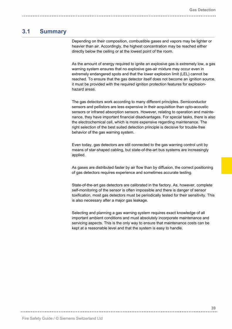
Matter consists of small particles, the atoms. Atoms comprise a positively charged atomic nucleus and a surrounding negatively charged electron shell. The electron shell determines which types of bonds with other atoms are possible. Chemistry thus takes place in the electron shell. As atoms compound either metals, salts or molecules may result. The objective of gas detection is to detect molecules con-tained in air, i.e. molecules occurring in gaseous form.
Figure 3.1: Physical states
Sublimate
Vaporize
Resublimate
CondenseMelt
Freeze
Gas Detection
41
Fire Safety Guide / © Siemens Switzerland Ltd
All pure substances may occur in any of the three physical states (see Figure 3.1). The lighter a molecule, the more frequently it occurs in gaseous form. Molecules with a molecular weight of less than that of air quite quickly diffuse in calm air. These molecules reach their highest concentration at the highest point of a room. Gases heavier than air – which is the case for most gases –, diffuse more slowly and reach their highest concentration level at the lowest point of a room.
3.2.2 Explosion and Explosion Protection
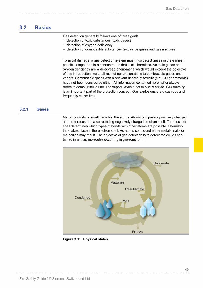
Gas and vapor are physically seen the same. Nevertheless, everyday usage established the differentiation as follows: One speaks of a gas if the substance is gaseous at room temperature and normal pressure. Vapor is used to address the evaporated (=gaseous state) part of a substance that is under normal conditions mainly liquid.
Figure 3.2: Explosion hazard due to escaping gas or liquid leakage
Combustible gases and vapors mixed with air can explode only within a certain concentration range. This so-called explosion range is defined by the lower and upper explosion limit (LEL and UEL). Below the LEL, most substances are harm-less; above the UEL, they remain combustible and are thus potentially hazardous. (In addition, a toxic effect sets in with most substances.)
Vapors Gases
Liquids
Gas Detection
42
Fire Safety Guide / © Siemens Switzerland Ltd
100%Combustion impossible
Not enough oxygen
Fuel
Combustion
Upper explosion limit (UEL)
Gas
con
cent
ratio
n
Lower explosion limit (LEL)
Explosion impossible
Application area of gas detection Ambient air
0%
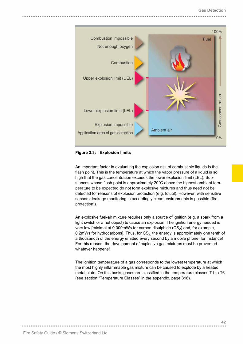
Figure 3.3: Explosion limits
An important factor in evaluating the explosion risk of combustible liquids is the flash point. This is the temperature at which the vapor pressure of a liquid is so high that the gas concentration exceeds the lower explosion limit (LEL). Sub-stances whose flash point is approximately 20°C above the highest ambient tem-perature to be expected do not form explosive mixtures and thus need not be detected for reasons of explosion protection (e.g. toluol). However, with sensitive sensors, leakage monitoring in accordingly clean environments is possible (fire protection!). An explosive fuel-air mixture requires only a source of ignition (e.g. a spark from a light switch or a hot object) to cause an explosion. The ignition energy needed is very low [minimal at 0.009mWs for carbon disulphide (CS2) and, for example, 0.2mWs for hydrocarbons]. Thus, for CS2, the energy is approximately one tenth of a thousandth of the energy emitted every second by a mobile phone, for instance! For this reason, the development of explosive gas mixtures must be prevented whatever happens! The ignition temperature of a gas corresponds to the lowest temperature at which the most highly inflammable gas mixture can be caused to explode by a heated metal plate. On this basis, gases are classified in the temperature classes T1 to T6 (see section “Temperature Classes” in the appendix, page 318).

Gas Detection
43
Fire Safety Guide / © Siemens Switzerland Ltd
Devices to be used in explosion-hazard areas can be enclosed in sealed, suffi-ciently strong housings (flame-proof enclosure) or may be set up in a way that they are intrinsically safe, i.e. they must be set up in such a way that no sparks may occur. Apart from this, there are several other, less frequent designs (see table in the appendix “Ignition Protection Classes” on page 317). The explosion group defines the application area for which a device is intended: − group I: electric appliances for mining − group II: electric appliances for areas with potentially explosive mixtures Group II is subdivided into the sub-groups IIA, IIB and IIC, with IIC being the strict-est, required for gases such as carbon disulphide (CS2), hydrogen (H2) or acety-lene (C2H2) (see section “Explosion Groups” on page 318). In selecting the gas detection system, make sure that its specifications are sufficient for the gases to be detected. With a gas like ethylene, for instance, the system must be specified at least according to sub-group IIB. With hydrogen, acetylene or carbon disulphide, the system must meet the requirements of sub-group IIC.

Gas Detection
44
Fire Safety Guide / © Siemens Switzerland Ltd
3.3 Using Gas Detection Technology
Gas detection technology should be used wherever hazardous gas concentrations may develop unnoticed. In case of temporary threats, portable gas warning sys-tems may help to ensure safety. However, in case of a permanent risk, fixed instal-lations are economically favorable. Dangerous concentrations can occur when, in case of leakage, the content of a gas cylinder is sufficient to reach the lower explosion limit in the room. With even lower concentrations, the gas remains combustible and may burn off and conse-quently produce a conflagration. The “Fire Protection Concept” (see page 28) should, at any rate, take such risks into account, considering the entire danger scenario. In case permanent supply of fresh air is ensured even in case of danger (e.g. redundant ventilation) the tolerable gas volume may increase. Areas in which combustible gases and vapors can occur are frequently assigned to so-called ex-zones (explosion protection zones). The type of ex-zone determines the nature of the risk. Please also refer to “Zone Division of Explosion Areas” on page 316.
Gas Detection
45
Fire Safety Guide / © Siemens Switzerland Ltd
3.4 Measuring Principles
In the course of the last decades, gas warning technology has constantly been improved and perfected. Thanks to this effort, today proven detection technologies are available that are very reliable if their application limits are respected. Only few areas know such different measuring principles as gas detection. For this reason, we will restrict our explanations to the most important principles in safety engineering, which fully automatically detect combustible gases or vapors.
3.4.1 Semiconductor Sensor
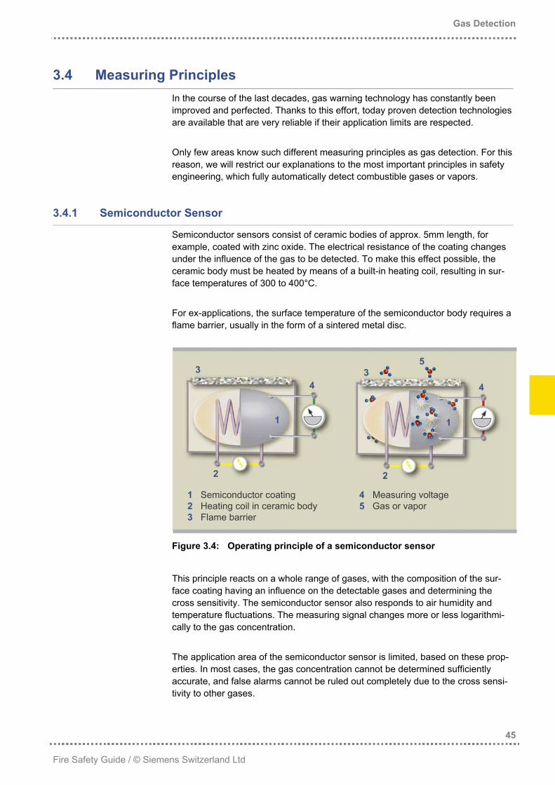
Semiconductor sensors consist of ceramic bodies of approx. 5mm length, for example, coated with zinc oxide. The electrical resistance of the coating changes under the influence of the gas to be detected. To make this effect possible, the ceramic body must be heated by means of a built-in heating coil, resulting in sur-face temperatures of 300 to 400°C. For ex-applications, the surface temperature of the semiconductor body requires a flame barrier, usually in the form of a sintered metal disc.
Figure 3.4: Operating principle of a semiconductor sensor
This principle reacts on a whole range of gases, with the composition of the sur-face coating having an influence on the detectable gases and determining the cross sensitivity. The semiconductor sensor also responds to air humidity and temperature fluctuations. The measuring signal changes more or less logarithmi-cally to the gas concentration. The application area of the semiconductor sensor is limited, based on these prop-erties. In most cases, the gas concentration cannot be determined sufficiently accurate, and false alarms cannot be ruled out completely due to the cross sensi-tivity to other gases.
1 Semiconductor coating 4 Measuring voltage 2 Heating coil in ceramic body 5 Gas or vapor 3 Flame barrier
Gas Detection
46
Fire Safety Guide / © Siemens Switzerland Ltd
3.4.2 Reaction Heat Sensor (Pellistor)
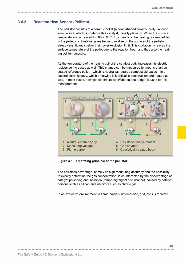
The pellistor consists of a ceramic pellet (a pearl-shaped ceramic body), approx. 2mm in size, which is coated with a catalyst, usually platinum. When the surface temperature is increased to 500 to 600°C by means of the heating coil embedded in the pellet, combustible gases begin to oxidize on the surface of the pellistor already significantly below their lower explosion limit. This oxidation increases the surface temperature of the pellet due to the reaction heat, and thus also the heat-ing coil temperature. As the temperature of the heating coil of the catalyst body increases, its electric resistance increases as well. This change can be measured by means of an un-coated reference pellet – which is neutral as regards combustible gases – in a second ceramic body, which otherwise is identical in construction and heated as well. In most cases, a simple electric circuit (Wheatstone bridge) is used for this measurement.
Figure 3.5: Operating principle of the pellistor
The pellistor's advantage, namely its high measuring accuracy and the possibility to exactly determine the gas concentration, is counteracted by the disadvantage of catalyst poisoning and inhibition (temporary signal disturbance), caused by catalyst poisons such as silicon and inhibitors such as chloric gas. In an explosive environment, a flame barrier (sintered disc, grid, etc.) is required.
1 Neutral ceramic body 4 Resistance measurement 2 Measuring voltage 5 Gas or vapor 3 Flame barrier 6 Catalytically coated body
Gas Detection
47
Fire Safety Guide / © Siemens Switzerland Ltd
3.4.3 Electrochemical Cell
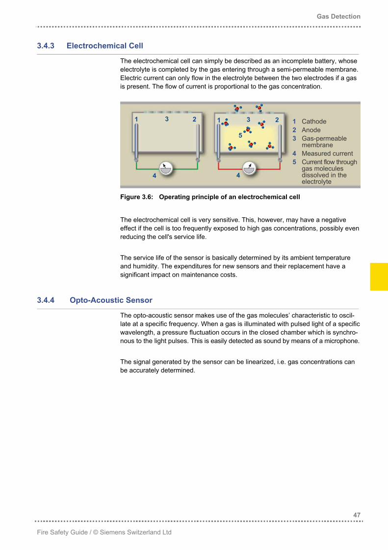
The electrochemical cell can simply be described as an incomplete battery, whose electrolyte is completed by the gas entering through a semi-permeable membrane. Electric current can only flow in the electrolyte between the two electrodes if a gas is present. The flow of current is proportional to the gas concentration.
Figure 3.6: Operating principle of an electrochemical cell
The electrochemical cell is very sensitive. This, however, may have a negative effect if the cell is too frequently exposed to high gas concentrations, possibly even reducing the cell's service life. The service life of the sensor is basically determined by its ambient temperature and humidity. The expenditures for new sensors and their replacement have a significant impact on maintenance costs.
1 Cathode 2 Anode 3 Gas-permeable
membrane 4 Measured current 5 Current flow through
gas molecules dissolved in the electrolyte
3.4.4 Opto-Acoustic Sensor
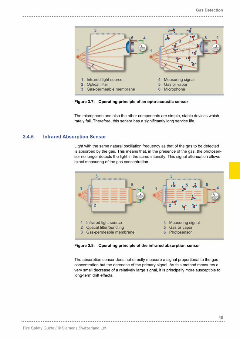
The opto-acoustic sensor makes use of the gas molecules’ characteristic to oscil-late at a specific frequency. When a gas is illuminated with pulsed light of a specific wavelength, a pressure fluctuation occurs in the closed chamber which is synchro-nous to the light pulses. This is easily detected as sound by means of a microphone. The signal generated by the sensor can be linearized, i.e. gas concentrations can be accurately determined.
Gas Detection
48
Fire Safety Guide / © Siemens Switzerland Ltd
Figure 3.7: Operating principle of an opto-acoustic sensor
The microphone and also the other components are simple, stable devices which rarely fail. Therefore, this sensor has a significantly long service life.
1 Infrared light source 4 Measuring signal 2 Optical filter 5 Gas or vapor 3 Gas-permeable membrane 6 Microphone
3.4.5 Infrared Absorption Sensor
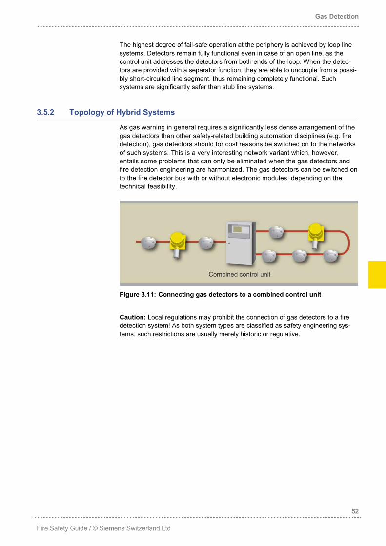
Light with the same natural oscillation frequency as that of the gas to be detected is absorbed by the gas. This means that, in the presence of the gas, the photosen-sor no longer detects the light in the same intensity. This signal attenuation allows exact measuring of the gas concentration.
Figure 3.8: Operating principle of the infrared absorption sensor
The absorption sensor does not directly measure a signal proportional to the gas concentration but the decrease of the primary signal. As this method measures a very small decrease of a relatively large signal, it is principally more susceptible to long-term drift effects.
1 Infrared light source 4 Measuring signal 2 Optical filter/bundling 5 Gas or vapor 3 Gas-permeable membrane 6 Photosensor

Gas Detection
49
Fire Safety Guide / © Siemens Switzerland Ltd
3.4.6 Comparison of the Detection Methods
The different detection methods are compared in the following table.
Sensor type Property
Semi-conductor Pellistor
Electro-chemical
cell
Opto-acoustic sensor
Infrared absorption
sensor Detection range ppm - %LEL %LEL ppm %LEL %LEL Selectivity / cross sensitivity - - ++ + ++ ++ Stability (drift) + - + ++ ++ Background noise (lower measuring threshold) 1% mr 1% mr 5% mr 1% mr 1% mr
Measuring accuracy - - + ++ ++ ++ Response time t90 [sec.] 10 15 - 30 10 - 60 <30 <10 Temperature dependence - - + - - ++ ++ Humidity impact - - + + + + Characteristics Logarithmic Linear Linear Linearized Linearized Sensor poisoning + - - - ++ ++ Sensor inhibitors - - - - ++ ++
Qua
lity
crite
ria
Sensor service life [years] 1 - 5 1 - 3 <1 - 3 5 - 10 5 - 10 Cost price ++ + - - -
Cos
ts
Maintenance costs + - - - ++ ++ mr : Measuring range
t90 : Time until the detector measures 90% of the actual gas concentration ++ : Very good + : Good - : Poor - - : Very poor
Table 3.1: Comparison of the gas sensor principles
Summarizing this table, one may state that semiconductor sensors can only be used when the ambient atmosphere is constant and when no concentration details are required. False alarms cannot be completely ruled out. The pellistor as the classic detector of combustible gases is endangered by sensor poisoning and sensor inhibitors. If these substances can be excluded, there is no other obstacle to using a pellistor. The electrochemical cell is rather expensive, especially regarding maintenance. However, it is the first choice due to its selectivity when a particular gas must be detected in very small concentrations. Due to its working principle, using the opto-acoustic sensor is more elegant than the infrared absorption sensor. Both methods are extremely well-suited to detect combustible gases and vapors and have the best properties of all the options considered.

Gas Detection
50
Fire Safety Guide / © Siemens Switzerland Ltd
However, it must be stated that conventional gas sensors of these types only respond to the hydrocarbon part of the gas, meaning that pure hydrogen, for ex-ample, is not detected. The still quite expensive purchase price of these sensors is balanced by the longer service life and the lower maintenance costs. When catalyst poisons or inhibitors cannot be completely ruled out, the opto-acoustic or infrared absorption principle must be favored. After all, not working detectors are worse than none at all!

Gas Detection
51
Fire Safety Guide / © Siemens Switzerland Ltd
3.5 Control Unit and Systems Engineering
Gas warning systems are basically made up of the control unit, the detectors and the communication links between detectors and control unit. With most systems, different gas detector types can be mixed on one line.
3.5.1 Topology of Monotype Systems
The classic cabling topology for gas warning systems is a star-shaped cabling topology. This type is perfectly suited for compact systems. When the system expands, cabling costs will increase disproportionately.
Figure 3.9: Gas warning control unit with star-shaped cabling
Cabling costs decrease significantly when detectors can be wired in series (e.g. bus wired). This may theoretically be effected without addressing, but this would unnecessarily complicate the localization of the usually invisible gas. For this reason, only addressable systems shall be used in gas detection.
Figure 3.10: Gas warning control unit with detector bus
Gas warning control unit
Loop line
Stub line
Gas warning control unit
Gas Detection
52
Fire Safety Guide / © Siemens Switzerland Ltd
The highest degree of fail-safe operation at the periphery is achieved by loop line systems. Detectors remain fully functional even in case of an open line, as the control unit addresses the detectors from both ends of the loop. When the detec-tors are provided with a separator function, they are able to uncouple from a possi-bly short-circuited line segment, thus remaining completely functional. Such systems are significantly safer than stub line systems.
3.5.2 Topology of Hybrid Systems
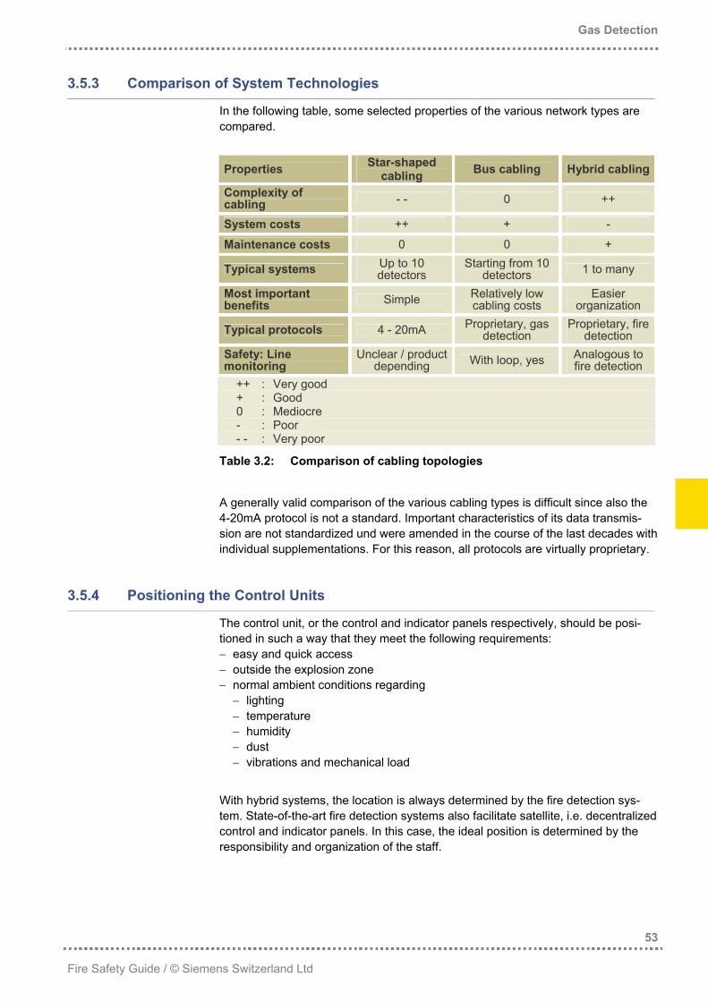
As gas warning in general requires a significantly less dense arrangement of the gas detectors than other safety-related building automation disciplines (e.g. fire detection), gas detectors should for cost reasons be switched on to the networks of such systems. This is a very interesting network variant which, however, entails some problems that can only be eliminated when the gas detectors and fire detection engineering are harmonized. The gas detectors can be switched on to the fire detector bus with or without electronic modules, depending on the technical feasibility.
Figure 3.11: Connecting gas detectors to a combined control unit
Caution: Local regulations may prohibit the connection of gas detectors to a fire detection system! As both system types are classified as safety engineering sys-tems, such restrictions are usually merely historic or regulative.
Combined control unit
Gas Detection
53
Fire Safety Guide / © Siemens Switzerland Ltd
3.5.3 Comparison of System Technologies
In the following table, some selected properties of the various network types are compared.
Properties Star-shaped cabling Bus cabling Hybrid cabling
Complexity of cabling - - 0 ++
System costs ++ + -
Maintenance costs 0 0 +
Typical systems Up to 10 detectors
Starting from 10 detectors 1 to many
Most important benefits Simple Relatively low
cabling costs Easier
organization
Typical protocols 4 - 20mA Proprietary, gas detection
Proprietary, fire detection
Safety: Line monitoring
Unclear / product depending With loop, yes Analogous to
fire detection ++ : Very good + : Good 0 : Mediocre - : Poor - - : Very poor
Table 3.2: Comparison of cabling topologies
A generally valid comparison of the various cabling types is difficult since also the 4-20mA protocol is not a standard. Important characteristics of its data transmis-sion are not standardized und were amended in the course of the last decades with individual supplementations. For this reason, all protocols are virtually proprietary.
3.5.4 Positioning the Control Units
The control unit, or the control and indicator panels respectively, should be posi-tioned in such a way that they meet the following requirements: − easy and quick access − outside the explosion zone − normal ambient conditions regarding
− lighting − temperature − humidity − dust − vibrations and mechanical load
With hybrid systems, the location is always determined by the fire detection sys-tem. State-of-the-art fire detection systems also facilitate satellite, i.e. decentralized control and indicator panels. In this case, the ideal position is determined by the responsibility and organization of the staff.
Gas Detection
54
Fire Safety Guide / © Siemens Switzerland Ltd
3.5.5 Integration in the Building Infrastructure
Unfortunately, many gas warning control units are still implemented as standalone devices. The relatively small savings are contrasted by an inadequate overview of the hazard situation in case of emergency and the extra effort required for the staff organization. Integrated systems facilitate easier handling and system interventions become safer, as the actions performed are also indicated elsewhere in the system, for example by the danger management system. Although this aspect is rather univer-sal, it is of particular significance in gas warning, as many suppliers of gas detec-tion systems have their roots in gas measuring technology and thus consider the integration of gas warning systems into the building infrastructure as relatively unimportant.
When the system integration into the building infrastructure is taken into account as early as possible, ideally already during the system evaluation phase, this will result in an essentially optimized organization.
Cost-optimized organization thanks to good system integration
Gas Detection
55
Fire Safety Guide / © Siemens Switzerland Ltd
3.6 Planning
To plan a gas warning system, it is essential to know the ambient conditions. The status of the environment must be recorded in a checklist. This includes: − substances to be detected − prevailing / associated substances − handling of these substances
− wherefrom stem which substances? − how are they transported, stored and processed?
− temperatures − humidity situation − wind conditions / ventilation − cleanliness of the atmosphere (sensor poisons and inhibitors!) Based on this information, the type, number, and position of the detectors can be determined. The question whether gas detectors are to be placed above the floor or below the ceiling is discussed in section 3.6.1. In doing so, the following aspects must be taken into account: • Gases and vapors are transported significantly faster by air currents than by
diffusion. • Room geometry, room equipment, machine temperature conditions, ventilation,
etc. ultimately determine the spreading of gases and vapors in case of leakage. Assessing the room geometry and ambient conditions is thus often more important for the detector arrangement than simple deliberations based on gas density. The simplest way to decide upon the placing of the detectors may be done with test tubes. A small amount of gas is released in a defined location. Using the test tubes, the resulting gas concentrations at the various possible detector locations are measured.
3.6.1 Vertical Detector Positioning
Most gases and vapors are heavier than air, which is why they mostly concentrate at the floor level and propagate the room in the form of plumes. Only very few gases, such as hydrogen (H2), methane (CH4), ammonia (NH3) and acetylene (C2H2) are lighter than air. Air has a relative molecular weight of 28 to 29 g/mole (depending on the composition). The molecular weight of a gas is easy to calculate by multiplying the molecular weight of the atoms and by adding them according to the molecular formula. Example: The molecular formula of acetylene (welding gas) is C2H2. This means that the molecule consists of 2 carbon atoms (C) and 2 hydrogen atoms (H).
Gas Detection
56
Fire Safety Guide / © Siemens Switzerland Ltd
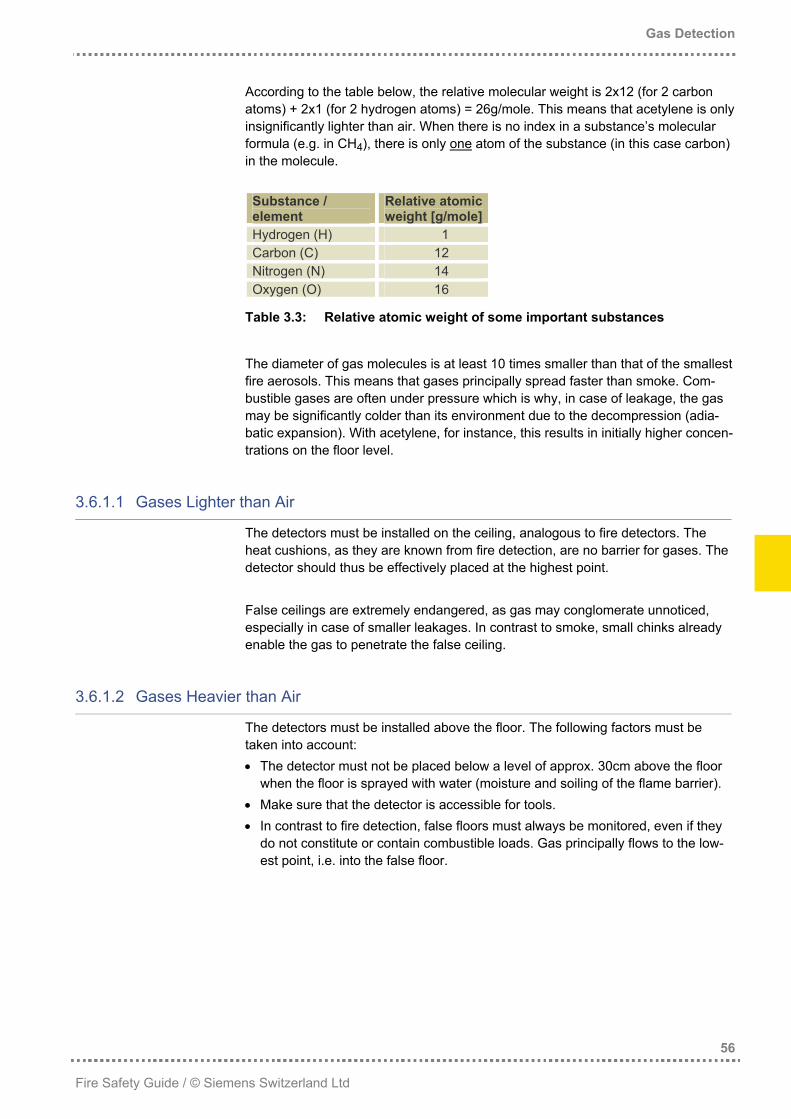
According to the table below, the relative molecular weight is 2x12 (for 2 carbon atoms) + 2x1 (for 2 hydrogen atoms) = 26g/mole. This means that acetylene is only insignificantly lighter than air. When there is no index in a substance’s molecular formula (e.g. in CH4), there is only one atom of the substance (in this case carbon) in the molecule. Substance / element
Relative atomic weight [g/mole]
Hydrogen (H) 1 Carbon (C) 12 Nitrogen (N) 14 Oxygen (O) 16
Table 3.3: Relative atomic weight of some important substances
The diameter of gas molecules is at least 10 times smaller than that of the smallest fire aerosols. This means that gases principally spread faster than smoke. Com-bustible gases are often under pressure which is why, in case of leakage, the gas may be significantly colder than its environment due to the decompression (adia-batic expansion). With acetylene, for instance, this results in initially higher concen-trations on the floor level.
3.6.1.1 Gases Lighter than Air
The detectors must be installed on the ceiling, analogous to fire detectors. The heat cushions, as they are known from fire detection, are no barrier for gases. The detector should thus be effectively placed at the highest point. False ceilings are extremely endangered, as gas may conglomerate unnoticed, especially in case of smaller leakages. In contrast to smoke, small chinks already enable the gas to penetrate the false ceiling.
3.6.1.2 Gases Heavier than Air
The detectors must be installed above the floor. The following factors must be taken into account: • The detector must not be placed below a level of approx. 30cm above the floor
when the floor is sprayed with water (moisture and soiling of the flame barrier). • Make sure that the detector is accessible for tools. • In contrast to fire detection, false floors must always be monitored, even if they
do not constitute or contain combustible loads. Gas principally flows to the low-est point, i.e. into the false floor.
Gas Detection
57
Fire Safety Guide / © Siemens Switzerland Ltd
3.6.2 Monitoring Areas
With light gases, the area to be monitored per detector can be up to 60m2 – analo-gous to fire detection – or, at room heights over 3m, up to 80m2. With gases heavier than air, the maximum monitoring area is 40m2 per detector.
3.6.3 Extent of Monitoring
Hazards need to be controlled. Also simple battery-charging stations did trigger explosions and need consequently to be monitored. Since it is often difficult to predict where a gas escape will exactly take place in endangered rooms, detectors should be spread evenly over the room surface. In case the risk in a larger room is locally restricted, object surveillance can be used instead of room surveillance. However, it must be ensured that in case of a modification to the system, the gas warning system is adapted accordingly. Object surveillance is often implemented in such a way that the detectors are installed directly above the equipment and not on the high ceiling. This prevents time delay and gas attenuation. To make sure that the gas reaches the detector, gas collectors are installed directly above the gas pipe or the machine. Rooms with unsealed connections to channels through which combustible gases or liquids are guided must also be monitored. When a high-sensitivity gas detection system is used, the possible leakage of combustible liquids can be monitored via the vapor phase. This facilitates fire protection of liquids which, under normal ambient conditions, do not form an explo-sive vapor-air mixture (high flash point). Regarding the detector arrangement, it can be summarized that laypersons may quickly be swamped with this task, as different factors are intertwined. Competent, expert consulting is thus of utmost importance.
Reliable gas warning thanks to correct planning
Gas Detection
58
Fire Safety Guide / © Siemens Switzerland Ltd
3.7 Installation, Commissioning and Acceptance
Today, detector calibration can be omitted in most cases, as the detectors are already calibrated in the factory prior to delivery. When periodic maintenance necessitates recalibration, this is essentially done with modern system support. Gas detection systems with the outdated two-men calibration cause additional maintenance costs in the long run. As there are many kinds of combustible gases and vapors, a calibration with the specific gas to be detected would be too complex and labor-intensive. For this reason, only few gases are still used for calibration purposes. These gases simu-late those to be detected, based on detector-specific conversion tables. After a gas escape has taken place, pellistor sensors always need to be checked. Besides the risk of accompanying catalyst poisons, there is the risk of sensor overload. This check is not required for opto-acoustic detectors, for example, which increases safety and lowers maintenance costs. Only perfect operation is sufficient. This is also valid in gas detection. Correspond-ingly important are the selection of the suppliers and the quality of services deliv-ered. Starting from planning the installation to maintenance, gas warning is a matter of confidence.
Gas Detection
59
Fire Safety Guide / © Siemens Switzerland Ltd
3.8 Profitability and System Evaluation
At the beginning of every planning, a careful situation and requirements analysis is a must. This defines largely which sensor technology is to be applied. Only with this technology a gas warning system will work properly and show reasonable maintenance costs. Quotations with other technologies may only be considered if they demonstrate clearly that they are able to operate even better with a still rea-sonable maintenance cost level. Cross sensitivities are sometimes welcome, but in most cases they represent a big nuisance in gas detection. Therefore, it is paying out to take the edge off the cross-sensitivity problem by taking architectural measures, for example with a partition wall. Among other things, system evaluation should also cover the following aspects: • The right networking is decisive for the installation costs as well as for further
expansion steps. Many manufacturers have their roots in the (in earlier times difficult) gas detection and therefore neglect the networkability of their products.
• Flexible system technology is paying off many times during the system’s life, because additional detectors may easily be added or detector locations may be changed without problems if the system is easily adaptable.
• Maintenance, testing, regular calibration and replacement of the sensors are important issues of gas detection. The supplier must be in a position to carry out this work efficiently. It is especially important that the replacement of the sensors is included in the maintenance contract. If the supplier is not in position to esti-mate the sensors’ life expectancy in the specific environment, he should at least provide a from-to indication of the costs including material, services and ex-penses for the sensor replacement.
• As soon as the word ”gas” is mentioned, some customer employees do not think they can cope with it. Hence, the supplier should be in a position to take care of the system short-term (e.g. acting as a deputy of the individual responsible for gas).