3. design standards 3.3 pavement design 3.3.1...
TRANSCRIPT

Chapter 23, Section 3.3 – Pavement Design DRAFT
City of Albuquerque Development Process Manual Page 1 of 14
Revised 10/12/2017
3. Design Standards
3.3 Pavement Design
3.3.1 General Provisions
The sections below provide requirements for the subgrade materials evaluation, traffic analysis, and design of flexible pavements, rigid pavements, and alternative pavements. Either the methods below or the design procedure from the New Mexico Department of Transportation (NMDOT) are acceptable for design of pavements in the City of Albuquerque.
The design method contained herein was developed by the review of various methods which are now, or have been in use by different state transportation departments and/or municipalities within the southwestern United States. These methods were all based on adoption and enhancement of the 1993 Guide for Design of Pavement Structures which was published by the American Association of State Highway and Transportation Officials (AASHTO). These methods were selected due to history of performance and due to the City of Albuquerque being in a specific geographic location where experience can be called upon and certain factors will not change.
Three major overall assumptions which have been made in the development of these design procedures are:
(a) That the adequacy of the design will be established by soils and material surveys and laboratory studies.
(b) That the design strengths assumed for the subgrade and pavement structure will be achieved through proper construction methods.
(c) That an adequate present and projected traffic loading for the analysis period be derived from accurate present and historical data in order to achieve the intended serviceability of the roadway.
3.3.2 Subgrade Materials Evaluation
3.3.2.1 Sampling Methods
1. The City of Albuquerque has chosen the R-Value test as its means of obtaining a resilient modulus for use in the 1993 AASHTO design equation for flexible pavements.
2. The correlation between R-Value and resilient modulus is presented in Table 3.3-1.
3. All soil tests shall be conducted under the supervision of a New Mexico Registered Professional Engineer familiar with soil sampling and testing procedures.

Chapter 23, Section 3.3 – Pavement Design DRAFT
City of Albuquerque Development Process Manual Page 2 of 14
Revised 10/12/2017
4. The design subgrade soil shall be defined as the upper two feet of the soil under the proposed pavement.
3.3.2.2 Frequency of Testing and Required Elements
Sampling frequency and techniques for subgrade materials (native and borrowed) shall be as follows:
1. One sample for each type of soil
2. A minimum of one sample every 300 feet for collector and arterial streets.
3. Two samples per project minimum.
4. One "R" value and proctor sample per each soil condition or three per mile of the poorest soil.
5. At least one and preferably two soil borings should go down to a depth comparable to any potential sewer or water line depth. A moisture determination should be made for each sample.
6. Sampling is to be random and shall not be restricted along any given line, but shall be spread irregularly over the proposed roadway.
7. The depth of sampling shall extend to a minimum depth of 3 feet below proposed subgrade elevation unless rock is encountered
3.3.2.3 Required Soil Tests
The following tests shall be performed on soil samples:
1. Sieve Analysis
2. Plastic Index
3. Soil correlation/analysis to determine representative soils, on which "R" value tests are to be performed.
4. With approval from the City Engineer, the designer can use NMDOT “Estimated R-value chart” based on soil type to supplement actual R-value test results on the subgrade soils encountered. Both the tested and estimated “R” values can be used to determine the design “R” value.
5. "R" value and Proctor density-moisture tests
6. Stabilization testing if subgrade stabilization is to be considered.
7. Determination of in-situ moisture content
3.3.2.4 Geotechnical Design Report
1. Pavement designs for local streets serving residential areas have been standardized and are presented in the Standard Details, Section 2400. These

Chapter 23, Section 3.3 – Pavement Design DRAFT
City of Albuquerque Development Process Manual Page 3 of 14
Revised 10/12/2017
standards are based on an R Value of 50 or greater. Soils investigation as outlined in the Subgrade Materials Evaluation section will be required to determine the nature of subgrade treatment needed to achieve the minimum R Value.
2. A design report shall be submitted for the construction of arterial, collector, or streets located in industrial areas. This report documents the existing pavement section material, thickness, and width and considers the design information regarding the proposed improvements. Any unusual circumstances which could affect design and/or construction should be noted. A site plan showing boring locations, soil boring logs and soil test results shall be provided.
3. The design “R” value is correlated to the Resilient Modulus (MR) for use in the flexible pavement design nomograph using Table 3.3-1.
Chapter 23, Section 3.3 – Pavement Design DRAFT
City of Albuquerque Development Process Manual Page 4 of 14
Revised 10/12/2017
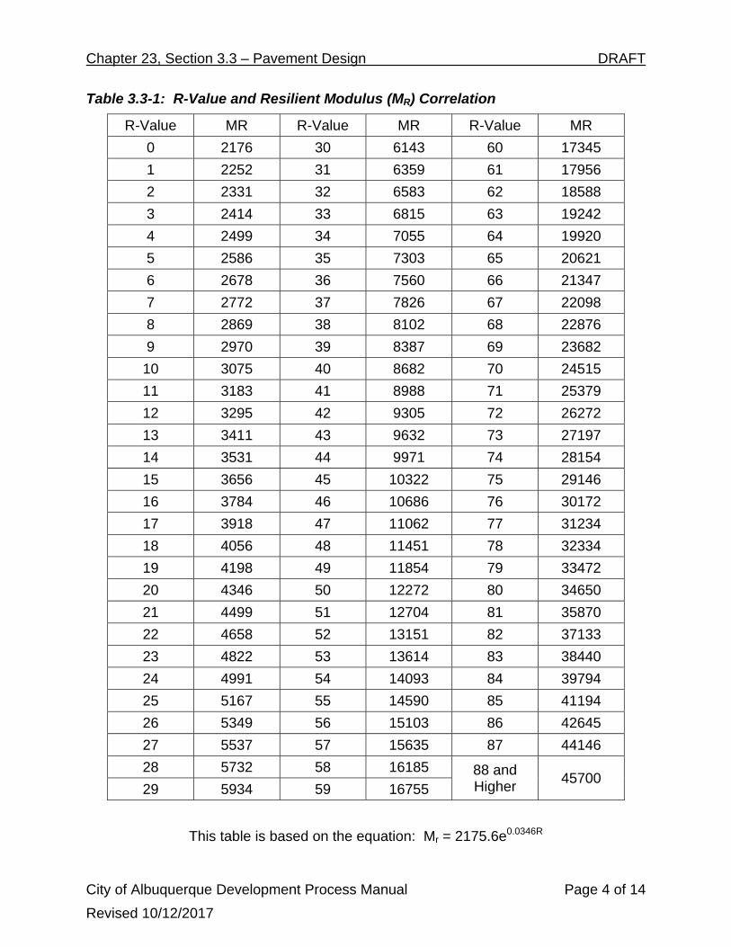
Table 3.3-1: R-Value and Resilient Modulus (MR) Correlation
R-Value MR R-Value MR R-Value MR
0 2176 30 6143 60 17345
1 2252 31 6359 61 17956
2 2331 32 6583 62 18588
3 2414 33 6815 63 19242
4 2499 34 7055 64 19920
5 2586 35 7303 65 20621
6 2678 36 7560 66 21347
7 2772 37 7826 67 22098
8 2869 38 8102 68 22876
9 2970 39 8387 69 23682
10 3075 40 8682 70 24515
11 3183 41 8988 71 25379
12 3295 42 9305 72 26272
13 3411 43 9632 73 27197
14 3531 44 9971 74 28154
15 3656 45 10322 75 29146
16 3784 46 10686 76 30172
17 3918 47 11062 77 31234
18 4056 48 11451 78 32334
19 4198 49 11854 79 33472
20 4346 50 12272 80 34650
21 4499 51 12704 81 35870
22 4658 52 13151 82 37133
23 4822 53 13614 83 38440
24 4991 54 14093 84 39794
25 5167 55 14590 85 41194
26 5349 56 15103 86 42645
27 5537 57 15635 87 44146
28 5732 58 16185 88 and Higher
45700 29 5934 59 16755
This table is based on the equation: Mr = 2175.6e0.0346R
Chapter 23, Section 3.3 – Pavement Design DRAFT
City of Albuquerque Development Process Manual Page 5 of 14
Revised 10/12/2017
3.3.3 Traffic Factors in Pavement Design
3.3.3.1 Traffic Criteria for Pavement Design
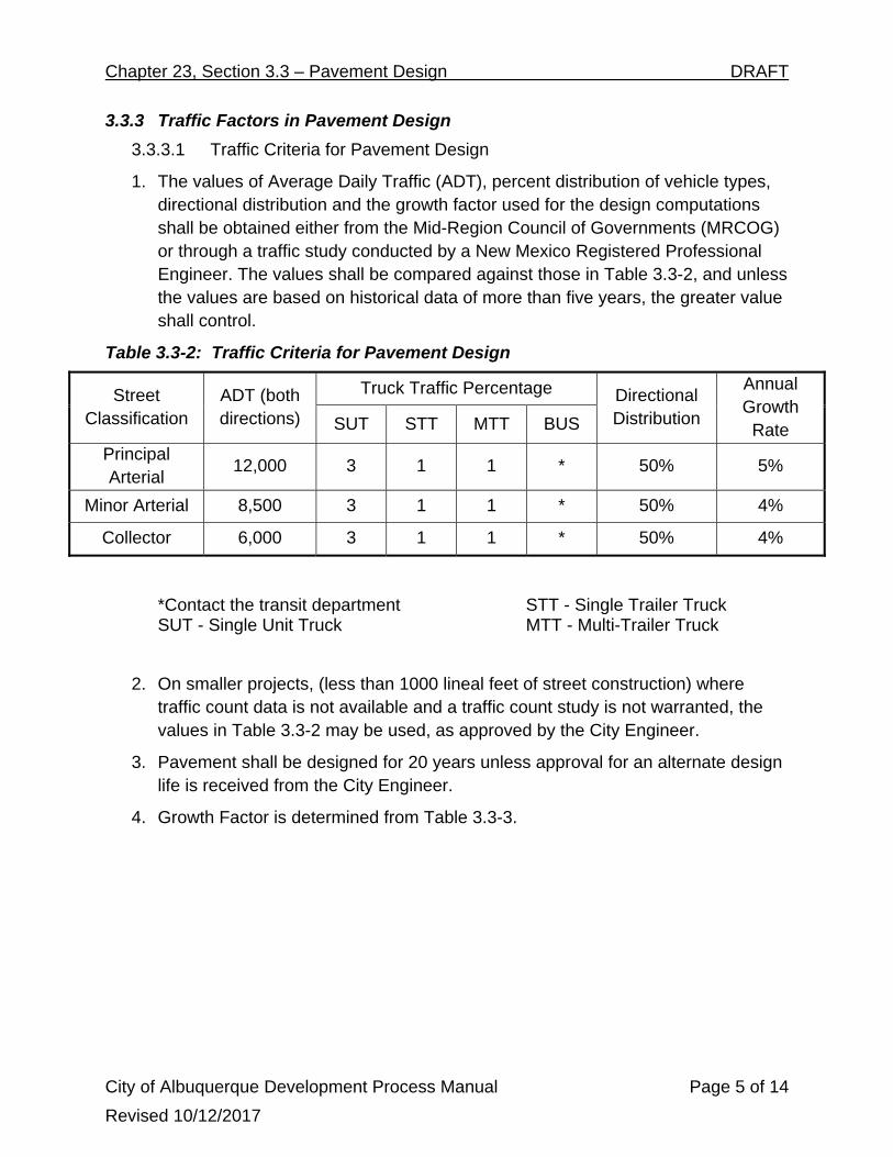
1. The values of Average Daily Traffic (ADT), percent distribution of vehicle types, directional distribution and the growth factor used for the design computations shall be obtained either from the Mid-Region Council of Governments (MRCOG) or through a traffic study conducted by a New Mexico Registered Professional Engineer. The values shall be compared against those in Table 3.3-2, and unless the values are based on historical data of more than five years, the greater value shall control.
Table 3.3-2: Traffic Criteria for Pavement Design
Street Classification
ADT (both directions)
Truck Traffic Percentage Directional Distribution
Annual Growth Rate SUT STT MTT BUS
Principal Arterial
12,000 3 1 1 * 50% 5%
Minor Arterial 8,500 3 1 1 * 50% 4%
Collector 6,000 3 1 1 * 50% 4%
*Contact the transit department SUT - Single Unit Truck
STT - Single Trailer Truck MTT - Multi-Trailer Truck
2. On smaller projects, (less than 1000 lineal feet of street construction) where traffic count data is not available and a traffic count study is not warranted, the values in Table 3.3-2 may be used, as approved by the City Engineer.
3. Pavement shall be designed for 20 years unless approval for an alternate design life is received from the City Engineer.
4. Growth Factor is determined from Table 3.3-3.
Chapter 23, Section 3.3 – Pavement Design DRAFT
City of Albuquerque Development Process Manual Page 6 of 14
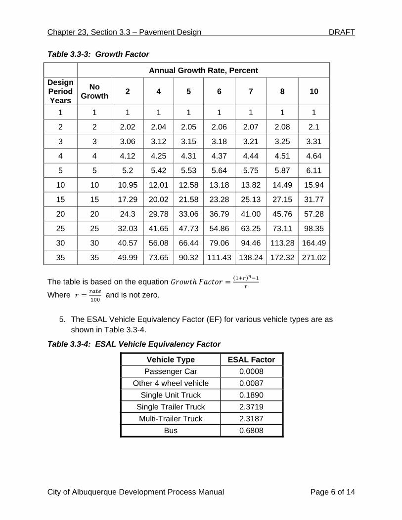
Table 3.3-3: Growth Factor
Annual Growth Rate, Percent
Design Period Years
No Growth
2 4 5 6 7 8 10
1 1 1 1 1 1 1 1 1
2 2 2.02 2.04 2.05 2.06 2.07 2.08 2.1
3 3 3.06 3.12 3.15 3.18 3.21 3.25 3.31
4 4 4.12 4.25 4.31 4.37 4.44 4.51 4.64
5 5 5.2 5.42 5.53 5.64 5.75 5.87 6.11
10 10 10.95 12.01 12.58 13.18 13.82 14.49 15.94
15 15 17.29 20.02 21.58 23.28 25.13 27.15 31.77
20 20 24.3 29.78 33.06 36.79 41.00 45.76 57.28
25 25 32.03 41.65 47.73 54.86 63.25 73.11 98.35
30 30 40.57 56.08 66.44 79.06 94.46 113.28 164.49
35 35 49.99 73.65 90.32 111.43 138.24 172.32 271.02
The table is based on the equation
Where and is not zero.
5. The ESAL Vehicle Equivalency Factor (EF) for various vehicle types are as shown in Table 3.3-4.
Table 3.3-4: ESAL Vehicle Equivalency Factor
Vehicle Type ESAL Factor
Passenger Car 0.0008
Other 4 wheel vehicle 0.0087
Single Unit Truck 0.1890
Single Trailer Truck 2.3719
Multi-Trailer Truck 2.3187
Bus 0.6808
Chapter 23, Section 3.3 – Pavement Design DRAFT
City of Albuquerque Development Process Manual Page 7 of 14
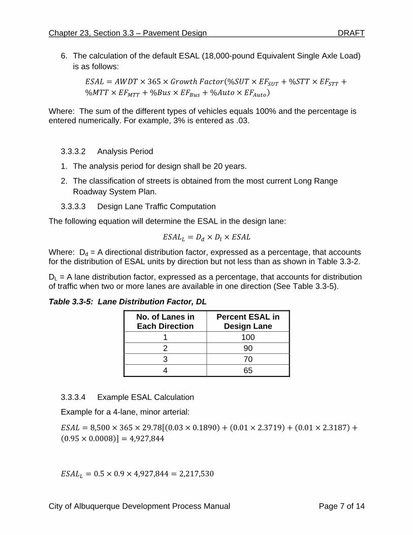
6. The calculation of the default ESAL (18,000-pound Equivalent Single Axle Load) is as follows:
365 % %% % %
Where: The sum of the different types of vehicles equals 100% and the percentage is entered numerically. For example, 3% is entered as .03.
3.3.3.2 Analysis Period
1. The analysis period for design shall be 20 years.
2. The classification of streets is obtained from the most current Long Range Roadway System Plan.
3.3.3.3 Design Lane Traffic Computation
The following equation will determine the ESAL in the design lane:
Where: Dd = A directional distribution factor, expressed as a percentage, that accounts for the distribution of ESAL units by direction but not less than as shown in Table 3.3-2.
DL = A lane distribution factor, expressed as a percentage, that accounts for distribution of traffic when two or more lanes are available in one direction (See Table 3.3-5).
Table 3.3-5: Lane Distribution Factor, DL
No. of Lanes in Each Direction
Percent ESAL in Design Lane
1 100 2 90 3 70 4 65
3.3.3.4 Example ESAL Calculation
Example for a 4-lane, minor arterial:
8,500 365 29.78 0.03 0.1890 0.01 2.3719 0.01 2.31870.95 0.0008 4,927,844
0.5 0.9 4,927,844 2,217,530

Chapter 23, Section 3.3 – Pavement Design DRAFT
City of Albuquerque Development Process Manual Page 8 of 14
3.3.4 Structural Design of Pavement
3.3.4.1 Minimum Pavement Component Thickness
The following criteria governing minimum pavement component thickness shall apply to all major (arterial and collector) roadways. These criteria, as listed in Table 3.3-6 are derived based on engineering judgment and past experience in construction quality control.
Table 3.3-6 Minimum Pavement Component Thickness
Pavement Component Minimum Thickness
Asphaltic Concrete (AC) 4 inches
Cement-Treated Base Course (CTB) 4 inches
Bituminous Treated Base Course (BTB) 4 inches
Aggregate Base Course (ABC) 4 inches
Subbase Material 4 inches
Soil Cement 6 inches
Asphalt Emulsion Treated Soil 6 inches
3.3.4.2 Structural Coefficients of Pavement Components
The following coefficients, listed in Table 3.3-7, shall be used for the computation of design structural number for each type of component selected:
Table 3.3-7 Structural Coefficients of Pavement Components
Component
Layer Coefficient
Modification Factor (mi)
Coefficient/Inch (ai)
Plant Mix Seal Coat (PMSC) N/A 0.25
Asphaltic Concrete (AC) N/A 0.42
Bituminous Treated Base Course (BTB) N/A 0.25
Cement Treated Base Course (CTB) N/A 0.20
Aggregate Base Course (ABC) 1.15 0.10
Sub-base Material 1.00 0.06
Asphalt Emulsion Treated Soil N/A Tentative
Soil Cement N/A Tentative
Lime Stabilization N/A Tentative
Chapter 23, Section 3.3 – Pavement Design DRAFT
City of Albuquerque Development Process Manual Page 9 of 14
1. The layer modification factor is applied to the base course layer coefficient to reflect the drainage or permeability characteristics of the selected base course.
2. Drainage coefficients are not applied to the asphaltic concrete layers, nor to the stabilized subgrade layers.
3. The modification factors may be set to other values than those recommended if the designer chooses.
4. The modification factors will range between 1.00 and 1.15 for bases approaching saturation less than 25% of the time, and base permits water removal with in one day.
5. Seek guidance from 1993 AASHTO Part 2, Section 2.4 for circumstances where the conditions stated do not apply.
The structural number is calculated using the depth in inches (di) for each layer as follows:
⋯
3.3.4.3 Serviceability Index
The serviceability of a pavement is defined as the ability to serve high-volume automobile and truck traffic. In the design equation, the serviceability index enters into the equation as the lowest index that will be tolerated before resurfacing or reconstruction becomes necessary.
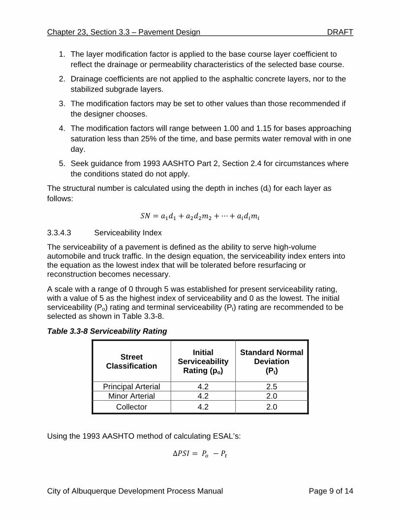
A scale with a range of 0 through 5 was established for present serviceability rating, with a value of 5 as the highest index of serviceability and 0 as the lowest. The initial serviceability (Po) rating and terminal serviceability (Pt) rating are recommended to be selected as shown in Table 3.3-8.
Table 3.3-8 Serviceability Rating
Street Classification
Initial Serviceability
Rating (po)
Standard Normal Deviation
(Pt)
Principal Arterial 4.2 2.5 Minor Arterial 4.2 2.0
Collector 4.2 2.0
Using the 1993 AASHTO method of calculating ESAL’s:
∆

Chapter 23, Section 3.3 – Pavement Design DRAFT
City of Albuquerque Development Process Manual Page 10 of 14
3.3.4.4 Reliability and Statistics
The AASHTO ‘93 method of calculation incorporates reliability and statistics to account for the degree of certainty how designs will perform as expected over the 20 year analysis period. For use in the 1993 AASHTO equation, recommended Reliability and Standard Deviation values are provided in Table 3.3-9 for Principal Arterial, Minor Arterial, and Collector Streets:
Table 3.3-9 Reliability and Statistical Values
Street Classification
Reliability Level
Standard Deviation (So)
Standard Normal Deviation (ZR)
Principal Arterial 85% 0.45 -1.037
Minor Arterial 80% 0.40 -0.841
Collector 75% 0.40 -0.674
Alternatively, the standard normal deviation as a function of reliability level may be chosen as from Table 3.3-10. It is not recommended to use a design reliability level of greater than 90%.
Table 3.3-10 Standard Normal Deviation Values
Reliability Level
Standard Normal Deviation (ZR)
50% -0.000 60% -0.253 70% -0.524 75% -0.674 80% -0.841 85% -1.037 90% -1.282
3.3.4.5 Economic Factors
The design engineer is encouraged to investigate the use of various combinations of pavement components in order to derive the most economic design applicable to the project characteristics and structural requirements.

Chapter 23, Section 3.3 – Pavement Design DRAFT
City of Albuquerque Development Process Manual Page 11 of 14
3.3.5 Flexible Pavements Design
3.3.5.1 Design Procedure
A nomograph from AASHTO ‘93 pavement design has been provided to simplify the solution to the mathematical relationship of the Resilient Modulus value, ESAL, and the structural number (Figure 3.3-1). Pavement structural designs shall be submitted in the format as shown on Table 3.3-11.
The equation for calculation of ESAL (W18) using AASHTO ‘93 is shown below:
9.36 1 0.2 ∆. .
. . 2.32 8.07

Chapter 23, Section 3.3 – Pavement Design DRAFT
City of Albuquerque Development Process Manual Page 12 of 14
Figure 3.3-1 Design Chart Flexible Pavements

Chapter 23, Section 3.3 – Pavement Design DRAFT
City of Albuquerque Development Process Manual Page 13 of 14
Table 3.3-11 Structural Design Computation Form
3.3.6 Portland Cement Concrete Streets
The current acceptable method for design of Portland cement concrete pavement is the procedure in the AASHTO Guide for Design of Pavement Structures, 1993 and the 1998 Supplement - Part II, Rigid Pavement Design and Rigid Pavement Joint Design published by the American Association of State Highway and Transportation Officials, Washington, D.C. As an alternative, PCCP design may be determined by use of accepted industry approach and software such as the American Concrete Pavement Association “Street Pave” software or NMDOT procedures.
Concrete pavement joints shall be detailed in the plans. Guidelines for joint layout can be obtained from the American Concrete Pavement Association.
Design criteria to be used in the structural design of Portland Cement Concrete Pavement (PCCP) are as follows:
1. All PCCP shall be fly-ash modified concrete as specified in the Standard Specifications or have other methods of mitigating Aggregate Silica Reaction as approved by the City Engineer.
2. Design of PCCP shall be based on flexural strength value of 600 psi at 28 days as measured by ASTM Method C 78.
3. Stabilized base course values used in conjunction with PCCP designs shall be as indicated below:

Chapter 23, Section 3.3 – Pavement Design DRAFT
City of Albuquerque Development Process Manual Page 14 of 14
a. Portland Cement Stabilized Base – 300 psi compressive strength as measured by ASTM Method D1633.
b. Asphalt Treated Base – 1000 pound minimum Marshal stability as measured by ASTM Method D1559 (as modified in the Standard Specifications.)
4. Reliability shall be 85%. 5. Final Serviceability Index shall be 2.5.
3.3.7 Alternative Pavement
Alternative types of pavement can be used for crosswalks, parking lots, sidewalks, and trails. Alternative materials must have sufficient strength for the projected traffic and require approval of the City Engineer. Crosswalks may be a different material from the remainder of the street. Options include:
Brick Pavers Permeable or Porous Pavement Stamped Concrete Gravel
3.3.6.1 Permeable or Porous Pavement
Requests to use permeable pavement shall include the following items:
1. Geotechnical investigation showing that the subgrade soils have sufficient percolation properties or a design that provides rainwater storage until percolation is achieved.
2. Agreement to maintain the pavement using sweeping, vacuuming or power washing.
3. Product information showing that the pavement meets American with Disabilities Act (ADA) requirements or indicate that a different material is used for ADA accessible parking spaces and accessible route.