3-d optimal shape design of ferromagnetic pole in mri magnet of open permanent-magnet type
TRANSCRIPT
IEEE TRANSACTIONS ON APPLIED SUPERCONDUCTIVITY, VOL. 12, NO. 1, MARCH 2002 1467
3-D Optimal Shape Design of Ferromagnetic Pole inMRI Magnet of Open Permanent-Magnet Type
Dong-Hun Kim, Byung-Sung Kim, Joon-Ho Lee, Wan-Soo Nah, and Il-Han Park
Abstract—This paper presents 3-D optimal shape designmethod of ferromagnetic pole pieces for magnetic resonanceimaging (MRI) devices of open permanent magnet type. Thedesign method is based on a continuum sensitivity analysis inconjunction with the boundary integral equation method (BIEM).The magnetic poles of an open magnet assembly are designed bythe proposed method and the conventional shimming method.Magnetic field strength, ppm order homogeneity and workingspace volume are compared between the proposed method andconventional one.
Index Terms—Homogeneous magnetic field, magnetic resonanceimaging (MRI) devices, open permanent magnet type, optimalshape design.
I. INTRODUCTION
T HE PERMANENT magnet assemblies for MRI deviceshave the medium field strength of about 0.1 T to 0.3 T. It is
well known that they have reasonable weight, size and price incomparison with resistive and superconductive magnet systems.In recent years, permanent magnet assemblies have been appliedto the manufacturing of MRI for wrist, ankle, finger, etc., as wellas for the whole human body. They are expected to be widelyused in clinics and have large market demand.
However, most design techniques of magnet assemblies forMRI have been restricted to determining dimension proportionsand arrangement of magnet assembly elements to provideuniform magnetic fields in the working space. The stochasticoptimization or the design of experiment where magnetic fieldswere calculated by finite element method or the magneticcircuit method in simplified 2-D model was usually employedas a design tool [1]–[4]. However, for the actual 3-D magnetmodel, these existing methods could not guarantee optimalhomogeneity condition of the magnetic field and workingspace volume constraint. Furthermore, they give no usefulinformation about the variety of admissible forms and typesof permanent magnet assemblies to a designer. The reason forthis is that they use approximate field solutions, and it is notadequate to deal with multi-parametric problems by using thezero-order sensitivity information.
This paper presents 3-D optimal shape design method for fer-romagnetic pole pieces of open permanent magnet type MRI de-vices. This design method uses continuum approach, which isbased on shape design sensitivity analysis of 3-D linear magne-
Manuscript received September 24, 2001.The authors are with the School of Electrical and Computer Engi-
neering, Sung-kyunkwan University, Suwon 440-746, Korea (e-mail:{dh29kim; jhlee}@nature.skku.ac.kr; [email protected]; {wsnah;ihpark}@yurim.skku.ac.kr).
Publisher Item Identifier S 1051-8223(02)04221-5.
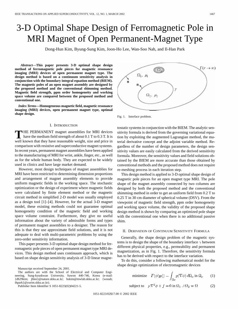
Fig. 1. Interface problem.
tostatic systems in conjunction with the BIEM. The analytic sen-sitivity formula is derived from the governing variational equa-tion by exploiting the augmented Lagrangian method, the ma-terial derivative concept and the adjoint variable method. Re-gardless of the number of design parameters, the design sen-sitivity values are easily calculated from the derived sensitivityformula. Moreover, the sensitivity values and field solutions ob-tained by the BIEM are more accurate than those obtained byconventional methods and the proposed method does not requirere-meshing process in each iteration step.
This design method is applied to 3-D optimal shape design ofmagnetic pole pieces for an open magnet type MRI. The poleshape of the magnet assembly connected by two columns aredesigned by both the proposed method and the conventionalshimming method in order to get an uniform field from 0.2 T to0.25 T in 30 cm diameter of spherical volume (DSV). From theviewpoint of magnetic field strength, ppm order homogeneityand working space volume, the validity of the proposed shapedesign method is shown by comparing an optimized pole shapewith the conventional one when there is no additional passiveshim.
II. DERIVATION OF CONTINUUM SENSITIVITY FORMULA
Generally, the shape design problem of the magnetic sys-tems is to design the shape of the boundary interfacebetweendifferent physical properties, e.g., permeability and permanentmagnetization, as in Fig. 1. Therefore, the sensitivity formulahas to be derived with respect to the interface variation.
To do this, consider a following mathematical model for theshape design optimization of electromagnetic devices
minimize in (1)
subject to in (2)
1051-8223/02$17.00 © 2002 IEEE

1468 IEEE TRANSACTIONS ON APPLIED SUPERCONDUCTIVITY, VOL. 12, NO. 1, MARCH 2002
where the objective function is defined as a function of thestate variable over the objective region an arbitraryfunction differentiable to and the design variable vector.Also, the state variable in (1) must satisfy Poisson’s equation (2)where and is the permanent magnetization.
Multiplying both sides of (2) by virtual variable and inte-grating them over the whole domain, the variational form ofthe governing equation is obtained as follows
for all (3)
where is the space of admissible state variable anddenotesthe transpose of a vector. Here, the state variable can be inter-preted as the magnetic scalar potential. Since the objective func-tion is normally nonlinear and implicit function of the designvariables, the augmented Lagrangian method is used as a non-linear programming method. The variational equation includingthe equality constraints (2) is multiplied by the Lagrange multi-plier vector instead of and is added to the objective function(1). Then the augmented objective functionis established as
(4)
where the subscripts, 1 and 2, mean the corresponding regionsand , respectively.
To obtain the variation of (4) with respect to the design vari-ables, we take the material derivative of continuum mechanics[5], [6] on both sides. The variational equation of the adjointsystem corresponding to the primary system can be easilyfound from the resultant equation (4). This variational equationis equivalent to the following differential equation
in (5)
where represents the applied loads in the ad-joint system related to the objective function (1). The Lagrangemultiplier referred to as the adjoint variable is obtained bysolving the adjoint system equation (5).
Using the adjoint variational equation and some formal op-erator equations, the augmented objective function (4) can besimplified as the boundary integration of the state and adjointvariables along only the movable interface as shown in (6)
(6)
where and mean unit vectors normal and tangential to theboundary surface, respectively. In the final design sensitivityformula (6), the first integral contributes to the derivative of theobjective function only when the boundary interface betweendifferent materials is modified and the second does only whenthe shape of the permanent magnet changes.
III. N UMERICAL CALCULATION OF DESIGNSENSITIVITY
After the sensitivity formula is obtained, one can calculate itsnumerical value by the following procedure:
I) Solve the system equation (2) for the state variablewhich is the reduced magnetic scalar potential;
II) Calculate the adjoint load in (5) with the state variableand the defined objective function;
III) Solve the adjoint equations (5) for the adjoint variable;IV) Calculate the sensitivity coefficient by the numerical
surface integration of the sensitivity formula (6).In I) and III), the state and adjoint variables are obtainable
by any BIEM which are based on the reduced magnetic scalarpotential formulation.
In this paper, the single layer BIEM is utilized as a com-putation tool. This formulation can reduce computing timeand storage memory by using the equivalent magnetic surfacecharge with one degree of freedom. According to this method,the BIE for (2) is expressed in terms of a single layer magneticsurface source as in (7)
(7)
where is the Green’s function for 3-D magnetostatic prob-lems, the magnetic field generated by the external currentsource or permanent magnet and denotes the relative per-meability. After solving (7), the state variable is given by themagnetic charge density distributed over the interface
(8)
And, the adjoint variable can be easily evaluated with the al-ready decomposed system matrix of (7) because the state andadjoint equations differ only in their load terms.
IV. I NVESTIGATION OF THEEFFECT OFPOLE PIECE SHAPES
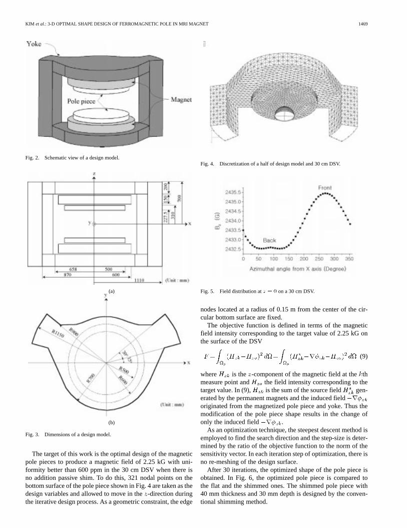
There are several construction types of permanent magnetsystems that can be used for MRI. In order to prove the validityof the proposed design method, we choose one that consists ofpole pieces, magnets and iron yoke connected by two columnsas shown in Fig. 2. This type is known to be more comfortable toa patient than the others with four columns. Fig. 3 presents thedimensions of the design model for its field analysis and polepiece design.
Before designing magnetic pole pieces, the initial model withthe flat pole pieces and an air gap of 455 mm is analyzed by theBIEM. It is considered that magnetic materials are far from thesaturation and the residual flux density of Nd–Fe–B magnet is1.21 T. A half model is discretized into 5066 triangular surfaceelements with 2557 nodes. Fig. 4 shows the discretized surfacemesh of a half of the model and a 30 cm DSV. Thecomponentof magnetic fields at on the DSV is not uniformly dis-tributed as shown in Fig. 5. This comes from the leakage fluxfrom the pole piece to two columns. From this result, we caninfer that 3-D magnetic field analysis is requested for obtainingaccurate field solutions and dealing with the high degree of ho-mogeneity of the magnetic fields.
KIM et al.: 3-D OPTIMAL SHAPE DESIGN OF FERROMAGNETIC POLE IN MRI MAGNET 1469
Fig. 2. Schematic view of a design model.
(a)
(b)
Fig. 3. Dimensions of a design model.
The target of this work is the optimal design of the magneticpole pieces to produce a magnetic field of 2.25 kG with uni-formity better than 600 ppm in the 30 cm DSV when there isno addition passive shim. To do this, 321 nodal points on thebottom surface of the pole piece shown in Fig. 4 are taken as thedesign variables and allowed to move in the-direction duringthe iterative design process. As a geometric constraint, the edge
Fig. 4. Discretization of a half of design model and 30 cm DSV.
Fig. 5. Field distribution atz = 0 on a 30 cm DSV.
nodes located at a radius of 0.15 m from the center of the cir-cular bottom surface are fixed.
The objective function is defined in terms of the magneticfield intensity corresponding to the target value of 2.25 kG onthe surface of the DSV
(9)
where is the -component of the magnetic field at thethmeasure point and the field intensity corresponding to thetarget value. In (9), is the sum of the source field gen-erated by the permanent magnets and the induced fieldoriginated from the magnetized pole piece and yoke. Thus themodification of the pole piece shape results in the change ofonly the induced field .
As an optimization technique, the steepest descent method isemployed to find the search direction and the step-size is deter-mined by the ratio of the objective function to the norm of thesensitivity vector. In each iteration step of optimization, there isno re-meshing of the design surface.
After 30 iterations, the optimized shape of the pole piece isobtained. In Fig. 6, the optimized pole piece is compared tothe flat and the shimmed ones. The shimmed pole piece with40 mm thickness and 30 mm depth is designed by the conven-tional shimming method.

1470 IEEE TRANSACTIONS ON APPLIED SUPERCONDUCTIVITY, VOL. 12, NO. 1, MARCH 2002
(a)
(b)
(c)
Fig. 6. Comparison of three pole piece shapes. (a) flat pole piece. (b) shimmedpole piece. (c) optimized pole piece.
TABLE IMAGNETIC FIELD STRENGTH AND FIELD-UNIFORMITY IN A 30 cm DSV
For comparison of three pole pieces, the field strength andfield-uniformity are calculated in each case and the results arelisted in Table I. And Fig. 7 shows the behavior of field-unifor-mity with respect to the variation of DSV from 30 cm to 35 cmin three cases. From the results of Table I and Fig. 7, it can beknown that the magnet assembly with the optimized pole piecesproduced the magnet field strength greater by 12.5% and uni-
Fig. 7. Behavior of field-uniformity with respect to the variation of DSV.
formity better by 46% in the 30 cm DSV than that with theconventional shimmed pole pieces. In addition, the optimizedpole pieces retain the better behavior of field-uniformity in DSVfrom 30 cm to 35 cm than the shimmed ones.
V. CONCLUSIONS
The numerical results validate the optimal shape designmethod of ferromagnetic pole pieces for MRI. They also showthat the proposed method can deal with multi-parametric prob-lems that cannot be approximated adequately using analyticalor simple numerical field calculation method based on axialsymmetry. Thus, the proposed algorithm can be widely usedto provide an optimum design method for the problem ofgenerating the homogeneous magnetic field and field intensityin the wanted volume, while minimizing the assembly size.
REFERENCES
[1] A. Podol’skii, “Design procedure for permanent magnet assemblies withuniform magnetic fields for MRI devices,”IEEE Trans. Magn., vol. 36,no. 2, pp. 484–490, Mar. 2000.
[2] J. H. Jensen, “Optimization method for permanent-magnet structures,”IEEE Trans. Magn., vol. 35, no. 6, pp. 4465–4472, Nov. 1999.
[3] Z. X. Feng, X. H. Jiang, and S. Han, “The design and construction ofhigh field-uniformity permanent magnet system for MRI,”IEEE Trans.Magn., vol. 28, no. 1, pp. 641–643, Jan. 1992.
[4] P. Molfino et al., “Design of an axisymmetric permanent magnet struc-ture for magnetic resonance tomography,”IEEE Trans. Magn., vol. 24,no. 2, pp. 994–997, Mar. 1988.
[5] E. Hardeeet al., “A CAD-based design parameterization for shape opti-mization of elastic solids,”Advances in Engineering Software, vol. 30,pp. 185–199, 1999.
[6] D.-H. Kim et al., “Shape design sensitivity analysis in 3-D linear magne-tostatic systems by continuum approach and boundary integral equationmethod,” inProc. CEFC 2000, June 2000, p. 132.