2d modeling with inkscape training manual v1 · 2012-05-29 · inkscape software in this course we...
TRANSCRIPT

INKSCAPE
[1]

Contents
Inkscape Software 4
Designing with Inkscape 5
The Inkscape Window 5
Guides 6
Grids 6
Zoom Tool 8
Special Notes Before Designing for the Laser Cutter 9
Selector Tool 9
Snap Controls Bar 14
Bezier Pen Tool 14
Editing at Path 15
Rectangle Tool 17
Ellipse Tool 17
Star Tool 18
Working With Objects 20
Aligning and Distributing 21
Working with Groups 23
Working With Clips and Masks 24
Fill and Stroke 25
Layers 26
Text Tool 29
Bitmap Tracing 29
[2]

Reference: Basic Keyboard Commands 30
Appendix 1: Inkscape (Import/Export Formats) 31
Appendix 2: Tutorial References 32
[3]

INKSCAPE SOFTWARE
In this course we will teach you the basics of Inkscape along with how this software tool can be used to prepare work for
the Laser Cutter and Vinyl Cutter.
InkscapeSoftware Description: Inkscape is a 2D vector graphics editor that has capabilities similar to Adobe
Illustrator using the Scalable Vector Graphics (SVG) file format. It uses a simple interface
making it is easy to edit nodes, perform complex path operations, trace bitmaps, and
more. Inkscape is an Open Source software, which means it can be downloaded
onto your PC for free of charge enabling you to design something at home and then
bring it into the lab for printing and assembly!
Website: http://www.inkscape.org
[4]

DESIGNING WITH INKSCAPEInkscape has capabilities similar to Illustrator using the Scalable Vector Graphics (SVG) file format. It uses a simple
interface making it is easy to edit nodes, perform complex path operations, trace bitmaps, and more. Inkscape is an
Open Source vector graphics editor, which means it can be downloaded onto a PC. This enables the user to design
something at home and then bring it into the lab for printing and assembly!
The Inkscape Window
[5]

GuidesGuides are user-defined “magnetic” lines. Using Guides makes object alignment easy even with the mouse. To use
Guides, click and drag from the Rulers to the point where the Guide is to be inserted and then release. Clicking and
dragging from the horizontal Ruler produces a horizontal Guide. Clicking and dragging from the vertical Ruler produces a
vertical Guide. To delete a guide, drag it to the appropriate Ruler with the Selector Tool (F1 or Space Bar)
Guides are also often used with snapping feature. This makes it much easier to place objects on the canvas, especially
with precise or technical drawings. In this case go to File > Document Properties and check the “Snap Guides While
Dragging” checkbox.
GridsInstead of using many Guides, it could be useful to activate Grids. This can be accomplished two different ways.
1. Go to File > Document Properties and then customize the Grid
2. Go to View > Grid (or press #)
Grids are of 2 types: Rectangular and Axonometric. Most commonly used is the Rectangular Grid which is made of
vertical and horizontal lines. (Axonometric Grids allow the user to define any kind of angled Grid which is useful for
technical and architectural drawings.)
Here is an example of a standard Axonometric Grid (left) and a Rectangular Grid (right)
[6]

Grid Customization Menu (...found by going to File > Document Properties)
How to Use
Within the Grid Customization Menu select which type of grid that will be used (Rectangle or Axonometric) and then
Click the "New" button. A new tab will appear under "Defined Grids" (...several grids can be defined for a single
document).
Enabled
Tick the box to use this grid in the current document.
Visible
Tick the “Visible” box to display the grid on the canvas. Switch off to make the grid invisible. This option sets the default
value for each grid so that even if Visible is ticked here, it is still possible to toggle View Grid on and off via the menu or
by hitting the # key. If the View > Grid menu is unchecked, the grid won't be visible on the canvas even if "Visible" is
checked here.
Grid Units
Many commonly used units are available. Within the Fab Lab, we suggest inches.
Origin X and Y
This defines the beginning point of the Grid. For Laser Cutter we suggest Origin “X” and Origin “Y” both be “0”. (It can
be useful to change these if an offset is needed, especially to define margins from the edge of the Canvas.)
Spacing X and Y
This defines the space between two lines of the Grid. These spaces can be different for horizontal and vertical lines so
that the Grid pattern can be set to any kind of rectangle.
[7]

Angle X and Z
This is only available for Axonometric Grids. It defines the angles for the Grid Lines on the X and Z axis.
Grid Line Color
The default color for the Grid is blue, but this can be changed here. There are two kinds of lines: Grid Lines and Major
Grid Lines. Most often used is the Grid Line, but when the grid spacing is short and many lines are displayed, the Major
Grid Lines help evaluate distances. In this case a different color can be defined for each type of line and the frequency of
the Major Grid Line can be set (usually 5 or 10).
Show Dots Instead of Lines
This is available on Rectangular Grid Only. Since lines can overload the screen, it can be uneasy working with Drawing
Tools when the grid is visible. This option toggles between lines and dots for displaying the grid, creating a less
overloaded screen.
Zoom ToolThe Zoom Tool is a great way to navigate the canvas. It can be accessed several ways. Each zoom action is saved in a
special history so that one can easily zoom and unzoom without difficulty. All zoom operations through the mouse
preserve the point under the cursor.
How to Use
• Clicking in the button
• Press F3
• Ctrl+Alt+Mouse wheel
• Shift+Middle Mouse Button
Zoom In
Press +
Middle Click zooms in
Zoom Out
Press -
Shift+Middle Click zooms out
Zoom to 1:1
Press 1 to display real drawing size
Zoom to 1:2
Press 2 to display at half the real
size
Adjust Selection to Window
Press 3 to make selected area fit
screen
Adjust Drawing to Window
Press 4 to make drawing fit screen
Adjust Page to Window
Press 5 to make page (or canvas) fit
screen
Adjust Page Width to Window
Press 6 to fit page (or canvas) width
to screen
Previous Zoom
Press ̀ repeatedly to navigate all
previous zoom settings. Press Shift
+ ̀ to Navigate forward in zoom
history.
Hot Keys
Middle Button+Drag pans canvas
Tips
• By default, rotating the mouse wheel scrolls the canvas vertically and Ctrl+wheel zooms in and out.
• Use Shift+Middle Button Drag to zoom into an area. This works the same as simple drag in Zoom tool, but is faster
because it does not require switching away from the current tool.
• In the Zoom tool, the Right Mouse Button always zooms out.
[8]

Special Notes Before Designing for the Laser Cutter
Document Size
Set document size to a width of 24” and a height of 12”. This is the cutting surface area of the Laser Cutter. This can be
accomplished by clicking File and going into Document Properties.
Vector Cutting
If a design is to be cut all the way through, it is important to set the line width to .001”. This can be accomplished
through the Fill and Stroke feature, which is enabled by going to OBJECT > Fill and Stroke (or bypressing Shft+Ctrl+F).
Be sure the stroke is enabled underneath the stroke tab. Underneath the Stroke Style tab enter the width as .001 inches.
Rastering
If a design is to be rastered (or engraved), it is important that the line width be greater than .010”. This can be
accomplished in the same way through the Fill and Stroke Feature. Logos, Bitmaps, and Objects with filled interiors will
automatically raster without any additional attention.
Selector ToolThe Selector Tool is used to select, position, and transform objects on the Canvas with the mouse or other input device.
How to Use
Click once on an object with the Selector Tool to select it. The object will be framed with a bounding box (a black,
dashed line) and scale handles. Click again on the same object and the scale handles will change to rotation and skew
handles. If the object is part of a group, the group will be selected, and dragging the object’s scale handles will transform
the group. Double-click an object with the Selector Tool and the tool will change to the appropriate tool to edit the object
(i.e., if you double-click an ellipse, the Ellipse Tool will be activated, etc.).
Selecting Objects
Click any object once to select it
Adding Objects to and Removing Objects from Selection
Shift+Clicking an additional object to what has already been selected adds that object to the current selection
Shift+Clicking an already highlighted object will also remove it from the selection
Rubberband Selection
Rubberband selection is made by Clicking on empty canvas space and dragging the rectangular "rubber band" over
several objects (i.e. click at one place and keep the button pressed while moving the mouse).
[9]

Touch Selection
Touch Selection allows you to select objects by drawing a freehand path across them. This mode is very convenient in
situations where objects are so intermingled that selecting them by the other methods is too difficult or tedious.
If you are drawing a rubberband rectangle, press Alt to switch it to the touch mode. The rectangle will disappear and a
red touch path will be shown instead. When dragging from an empty space, you can press first Alt and then start to drag
to get the touch mode (note that selection must be empty, otherwise Alt dragging will move the selected objects). To
start a touch selection from a point over an object, or to add to an existing selection by touching, press Shift+Alt and
then start to drag.
Inverting Object Selection
Use “!” to invert the selection to all unselected objects within the current layer.
Use Alt+! to invert the selection to all unselected objects within all unlocked layers.
Moving Objects
To move an object or an object group with the mouse, click on the object and hold the mouse button while dragging to
the new location. Dragging an object or several objects while holding Ctrl enables the objects to maintain alignment on
an axis. To move objects precisely with the Selector Tool, use either of these two methods:
1. Press the keyboard's cursor arrow to move selected objects 2px in direction of the arrow. (This default step can be
changed in Inkscape Preferences.)
2. Enter the coordinates into the Tool Control Bar X and Y coordinate controls to position the bottom left corner of the
selection's bounding box with precision.
Transforming Objects
There are two modes within the Selector Tool which are used to transform objects: Scale and Rotate/Shear
modes. Scale and Rotate/Shear modes can be toggled with the mouse or keyboard:
• Activate Scale mode by selecting an object with only one click.
• Activate Rotate/Shear mode by selecting an object with two clicks.
Switch between modes by pressing Shift+S while using the Selector Tool.
[10]
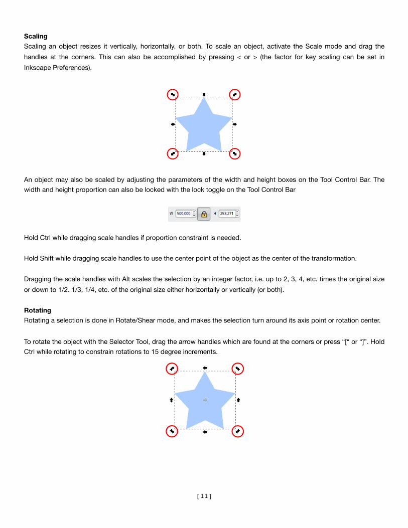
Scaling
Scaling an object resizes it vertically, horizontally, or both. To scale an object, activate the Scale mode and drag the
handles at the corners. This can also be accomplished by pressing < or > (the factor for key scaling can be set in
Inkscape Preferences).
An object may also be scaled by adjusting the parameters of the width and height boxes on the Tool Control Bar. The
width and height proportion can also be locked with the lock toggle on the Tool Control Bar
Hold Ctrl while dragging scale handles if proportion constraint is needed.
Hold Shift while dragging scale handles to use the center point of the object as the center of the transformation.
Dragging the scale handles with Alt scales the selection by an integer factor, i.e. up to 2, 3, 4, etc. times the original size
or down to 1/2. 1/3, 1/4, etc. of the original size either horizontally or vertically (or both).
Rotating
Rotating a selection is done in Rotate/Shear mode, and makes the selection turn around its axis point or rotation center.
To rotate the object with the Selector Tool, drag the arrow handles which are found at the corners or press “[“ or “]”. Hold
Ctrl while rotating to constrain rotations to 15 degree increments.
[11]

Rotation Center
The Rotation Center of the selected object specifies the point around which to rotate the object. It looks like a crosshair
and may be placed anywhere on the canvas, not just within the bounding box of the object. When several objects are
selected, they use the rotation center of the first selected object. If the first object does not have center set (i.e. if it's in a
default central position), then several objects will rotate around the geometric center of their common bounding box
To move the rotation center of an object, click and drag the crosshair to the desired spot. It will snap to the bounding
box of the object as well as other snap points as set in the Preferences.
See the comparison of the rotation point at the object’s center (left) VS the rotation point in the upper right corner of the
object (right):
Shift+Click on the rotation center resets it back to the center of the object's box.
Skewing or Shearing
Skewing or shearing objects can be done in the Rotate/Shear mode as well. This transformation shifts the parallel
bounding edges of the selection in opposite directions so that the selection is warped diagonally.
To skew the object with the Selector Tool, just drag the arrow handles placed at the middle of each sides. Horizontal
handles will skew horizontally, meaning that horizontal line will keep preserved and only the vertical line will be affected.
[12]

Mirroring
Mirroring flips a selection either vertically or horizontally. Flipping a selection while in Scale mode makes it flip within its
bounding box so that the bounding box remains fixed.
In Rotate/Shear mode, mirroring happens about an (imaginary) vertical/horizontal axis through the rotation center:
To mirror an object vertically, select Object->Flip Vertical or press V.
To mirror an object horizontally, select Object->Flip Horizontal or press H.
There are also two buttons in the options bar that can do the same:
Scaling of Stroke Width, Rectangle Corners, and Fills
There are four preferences represented by four toggle buttons in the Tool Controls Bar that control:
1. Stroke width scale
2. Radii of rounded corners
3. Gradient fills within an object
4. Pattern fills within an object
Tips
• The Transform Window (Object > Transform or Shift+Ctrl+M) can be used for precise transformations.
• Press Esc to deselect, cancel selection, or cancel drag or transformation.
• Ctrl+Click or Shift+Ctrl+Click will select objects within groups from outside that group.
• In the Selector Tool, Alt+Click selects the object at the cursor which is below (in z-order) the currently selected object
at the cursor; if the bottom object is reached, Alt+click again selects the top object. Thus, several Alt+clicks will cycle
selection through the z-order stack at the click point. Combining Alt with Ctrl ("select in groups") and Shift ("add to
selection") works, too.
• In the Selector Tool, Alt+Drag moves the currently selected object(s) no matter where the drag is started. Unlike regular
drag, this first selects the object under the cursor. This is convenient for dragging objects that are behind other objects
in z-order.
[13]

Snap Controls Bar
The Snap Controls Bar gives easy access to object snapping enabling the snapping feature to be quickly turned on
when required and off when finished. It also allows customization of the snapping feature regarding what can be
snapped and what objects can snap to.
Bezier Pen ToolThe Bezier Tool enables smooth curves to be drawn with precision.
How to use Bézier
To create a Bezier curve in Inkscape, click on the button in the Toolbox, or press b. Left click to create the first node.
To draw a segment, click again further where the segment should end. Inkscape immediately draws a straight line
between these two points.
Delete a Segment
To erase the last segment/node, press Delete.
Draw a Curve
To draw a curve, keep the button pressed after clicking and drag to make curve control point appear. They are
symmetrically placed to make a perfectly smooth curve so that only one node is needed. To stop drawing the actual
curve either click the first node of the global curve (if you want it to be a closed shape), or press Enter or double-click.
Continue a Path
To continue a path that has been previously drawn, press b to activate the Pen and click on either the beginning or the
end. A pen made path can be continued with the Pencil (F6) if needed.
Tips
Right-Click closes the shape but doesn't add any new points. It then becomes a path that can be edited with any other
tool like the Node Tool (F2). Further editing of any curve can be accomplished with the Node Tool.
[14]

Editing at PathAdd a Node
Option 1: Choose “Edit Paths by Nodes” in the Tool Box and “Insert New Nodes into Selected Segments”
Option 2: Double-Click or Ctrl+Alt+Click on a segment to add a node to a location
Delete a Node
Option 1: Choose “Edit Paths by Nodes” in the Tool Box and “Delete Selected Nodes”
Option 2: Ctrl+Alt+Click a node to delete it, or select the node and press Delete or Backspace. With either option
Inkscape will modify the handles on the remaining nodes to try to preserve the shape of the path. If this
isn’t necessary, press Ctrl+Delete or Ctrl+Backspace.
Delete keeps shape by adjusting adjacent node handles Ctrl+Delete does not preserve the shape
Split/Break a Node
Option 1: Choose “Edit Paths by Nodes” in the Tool Box and “Break Path at Selected Nodes”
Option 2: Select node, press Shift+B to split
It may not be obvious a node has been until it has been moved
Combine/Join Nodes
Option 1: Choose “Edit Paths by Nodes” in the Tool Box and “Break Path at Selected Nodes”
Option 2: Select two end nodes and press Shift+J to combine them into one node.
Continue / Append an Open Path
Select the path and start drawing from one of the end nodes with the Bezier Tool . (See image on following page.)
[15]

Delete a Segment
Option 1: Choose “Edit Paths by Nodes” in the Tool Box and “Delete Segment Between Two Non-Endpoint
Nodes”
Option 2: Select the segment, or the two nodes at either end of the segment, and press the button to delete it.
Join Nodes With a New Segment
Option 1: Choose “Edit Paths by Nodes” in the Tool Box and “Join Selected End-Nodes With a New
Segment”
Option 2: Select the two end nodes and press the button to create a segment between them
Change Node Type
Option 1: Choose “Edit Paths by Nodes” in the Tool Box and “Make Connected Nodes...Corner, Smooth,
Connected” Option 2: Press Shift+C to make a Cusp Node. Press Shift+S to make a smooth node. Press Ctrl+Delete to make a
smooth node with symmetrical handle lengths. Alternatively, Ctrl+Clicking node will toggle
through each node type.
A smooth node is indicated by a square while a cusp node uses a diamond
[16]

Rectangle ToolSquares and rectangles can be drawn by pressing the F4 button or r button.
How to Use
A new rectangle is drawn while the tool is active by pressing the left mouse button and dragging the mouse.
Rectangles have two resize handles in opposite corners. Dragging the handle resizes rectangles width and height
together.
Rectangles have corner radius handles to set the shape of the corners. There are two radius dimensions which can be
set together or independently.
Tips
• Ctrl+Drag on the handles will constrain the width and height of the rectangle while resizing so that they retain their
current ratios; when drawing a new rectangle, this method will create a perfect square.
• Shift+Drag on the handles will resize the rectangle from its center and not from the opposite corner of the grabbed
handle; when drawing a new rectangle, the rectangle will be drawn with its center at the starting point rather than one
of its corners.
• SHIFT+Click on a rounding handle will remove rounding.
• CTRL+Click on a rounding handle will make rounding radii equal.
Ellipse ToolAn ellipse, circle, or arc can be drawn by pressing the F5 button or e button. The object created with the Ellipse tool can
be converted from an ellipse to an arc, and can be transformed into any elliptical shape.
How to Use
When the ellipse is first drawn with the Ellipse tool, there are three edit handles - top, left and right.
The top and left square handles control the horizontal and vertical dimensions of the shape.
[17]

The right round handle edits the arc of the shape. Dragging the right handle with the Ellipse tool in either direction,
horizontal or vertical, will start an arc. When the tool is moved inside the bounds of the shape (...of the ellipse) the arc will
be open. When the tool is dragging the arc and is moved outside the bounds of the shape, the arc will be closed and
create a pie shape.
Tips
• Hold Ctrl while dragging the arc control to enable snapping at angles.
• Hold Shift while drawing to draw the shape with its center at the cursor's point of origin to keep position static during
the drawing.
• Hold Ctrl while drawing to keep the bound of the ellipse always touching the cursor - otherwise the cursor indicates
the intersection of the x and y bound coordinates.
Star ToolStars and Polygons are special shapes, difficult to draw by hand while maintaining a regular shape. The Star Tool permits
Stars and regular Polygons to be easily drawn. This tool is very convenient even though it may not be used as much as
the Rectangle Tool and Ellipse Tool.
Stars can be modified after creation, with handles or tool control parameters. By modifying some of the following
parameters, this tool can be used to draw triangles and other regular polygons with any number of sides. The included
deformation methods allow for some amazing shapes, all while keeping the powerful aspects of easy edit-ability.
How to Use
To switch to the Star Tool, either clicking the Toolbox icon or pressing *
Options
The tool options can be accessed in the Tool Controls bar
Drawing a Regular Polygon or Star
The left icons allow use of the Regular Polygon Mode or the Star Mode
Any other polygon/star can be created in the Selected Mode.
[18]
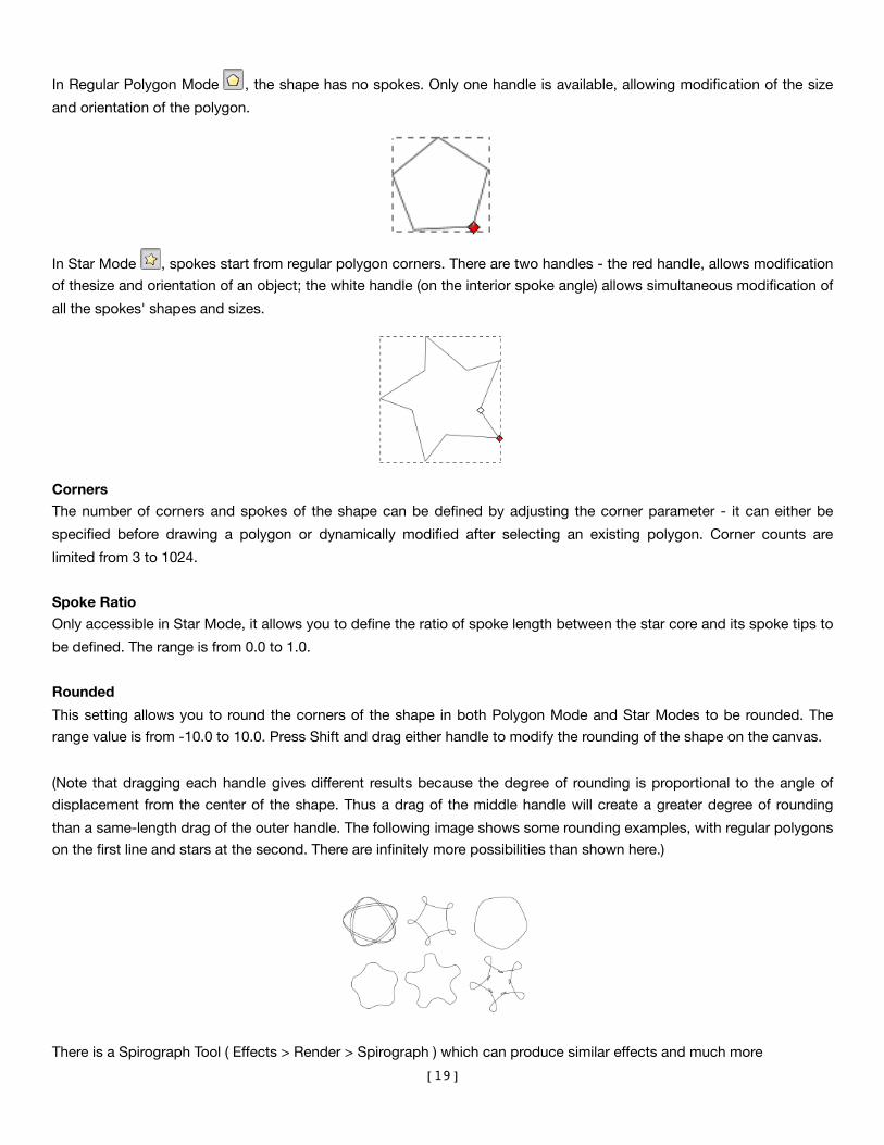
In Regular Polygon Mode , the shape has no spokes. Only one handle is available, allowing modification of the size
and orientation of the polygon.
In Star Mode , spokes start from regular polygon corners. There are two handles - the red handle, allows modification
of thesize and orientation of an object; the white handle (on the interior spoke angle) allows simultaneous modification of
all the spokes' shapes and sizes.
Corners
The number of corners and spokes of the shape can be defined by adjusting the corner parameter - it can either be
specified before drawing a polygon or dynamically modified after selecting an existing polygon. Corner counts are
limited from 3 to 1024.
Spoke Ratio
Only accessible in Star Mode, it allows you to define the ratio of spoke length between the star core and its spoke tips to
be defined. The range is from 0.0 to 1.0.
Rounded
This setting allows you to round the corners of the shape in both Polygon Mode and Star Modes to be rounded. The
range value is from -10.0 to 10.0. Press Shift and drag either handle to modify the rounding of the shape on the canvas.
(Note that dragging each handle gives different results because the degree of rounding is proportional to the angle of
displacement from the center of the shape. Thus a drag of the middle handle will create a greater degree of rounding
than a same-length drag of the outer handle. The following image shows some rounding examples, with regular polygons
on the first line and stars at the second. There are infinitely more possibilities than shown here.)
There is a Spirograph Tool ( Effects > Render > Spirograph ) which can produce similar effects and much more
[19]

Randomized
The Randomized option of the Star Tool displaces the inner and outer points of the spokes to random coordinates
around the center of the star. The range is from -10.0 to 10.0. Near 0.0, the randomness of the displacement ratio is low,
and it increases as the parameter approaches -10.0 or 10.0. The power of the randomized effect on-screen can be
changed by pressing Alt and dragging the handle.
Additional Information
• Polygons are always drawn with their geometric centers at the cursor origin (this cannot be changed).
• Ctrl+Drag on handles constrains the star shape.
Working With ObjectsTo clarify, an object is a general term to describe all shapes that make up a drawing. Text, shapes, paths, anything
drawn, is an object. This also includes groups of objects.
Selecting Objects
To Select an object use the button OR simply press F1 or the Space Bar
Selecting an Obscured Object
Sometimes an object can’t be selected because another object is above it. The selection of objects can be cycled
through by pressing Tab or by using Alt+Click to cycle through selecting just the objects below the mouse cursor.
Resizing and Rotating an Object
Select an object to show its transform handles. Click the object again to toggle rotation handles for the object.
[20]

Ordering Objects
To raise or lower an object’s order press Page Up or Page Down respectively. To raise or lower an object to the very top
or very bottom press Home or End respectively.
Duplicating Objects
Press Ctrl+D to Duplicate an object. This is similar to copying and pasting an object except it's position is the same as
the original.
Cloning Objects
Cloning is similar to duplicating except the clone maintains a link to the original so when you edit the original object the
changes will be reflected in clones also. To clone an object press Alt+D. To select the original object while a clone is
selected press Shift+D. A clone can be unlinked from the original by pressing Shift+Alt+D while the clone is selected.
Aligning and DistributingAlign and Distribute moves multiple selected objects to the same axis and distributes them equally relative to a selected
anchor object. The Align and Distribute dialog offers many ways of applying these functions to object selections.
[21]

How to Use
The Align and Distribute dialog can be called by pressing Shift+Ctrl+A, selecting Object > Align and Distribute, or by
clicking the icon on the Toolbar: Ensure objects are selected. Depending on which object will be the anchor and
which will be relative to the anchor, order of selection will be important.
"Relative To"
Objects can be aligned and distributed relative to:
• The last or first selected
• The biggest or smallest item
• The page
• The drawing (all objects within the document)
• The selection of objects
Align
To align selected objects, click the Align icons:
• Align right sides of objects to left side of anchor
• Align left sides
• Center on vertical axis
• Align right sides
• Align left sides of objects to right side of anchor
• Align baseline anchors of text vertically
• Align bottoms of objects to top of anchor
• Align tops
• Center on horizontal axis
• Align bottoms
• Align tops of objects to bottom of anchor
• Align baseline anchors of texts horizontally
Distribute
To distribute selected objects, click the Distribute icons:
• Distribute left sides equidistantly
• Distribute centers equidistantly horizontally
• Distribute right sides equidistantly
• Make horizontal gaps between objects equal
• Distribute baseline anchors of text horizontally
• Distribute tops equidistantly
• Distribute centers equidistantly vertically
• Distribute bottoms equidistantly
• Make vertical gaps between objects equal
• Distribute baseline anchors of text vertically
• Randomize centers in both dimensions
• Un-clump objects; try to equalize edge-to-edge
distances
Remove overlaps
These can also be defined:
• Minimum horizontal gaps between objects
• Minimum vertical gaps
Move objects as little as possible so their bounding
boxes do not overlap
Connector Network Layout
If using the connector tool and the connected objects
need to be distributed, this button will rearrange the
selected connectors.
Nodes
There are four buttons to organize nodes in path. Select
the nodes with Node Tool and click one of the Align node
buttons:
• Align selected nodes horizontally
• Align selected nodes vertically
• Distribute selected nodes horizontally
• Distribute selected nodes vertically
[22]

Working with GroupsGroups are a way of grouping multiple objects into a new object that can be treated the same as a regular object. Even
after grouping, individual objects within the group can still be edited.
Grouping and Ungrouping
To group multiple objects press Ctrl+G and to ungroup press Ctrl+U.
Selecting Objects Within a Group
To select an object within a group Ctrl+Click. Use Ctrl+Alt+Click to select obscured objects in a group. This is true for
clips and masks as well. Alternatively, a group can be entered into by pressing Ctrl+Enter OR by Double-Clicking and
then selecting the objects as normal. To break out of the group, press Ctrl+Backspace or select an object outside of the
group.
Add Objects to a Group
Press Ctrl+Enter or Double-Click to enter the group and then draw or paste the new object to include it in the group.
[23]

Working With Clips and MasksClips and Masks are used to restrict what parts of an object are visible. The shape of the object used as a clip defines
the area that is visible while the transparency or lightness of an object used as a mask determines the area that is visible.
Defining a Clip or a Mask
Select two objects and make sure the top most object is the object that will be used as the clip/mask. Select Set for
either Clip or Mask under the Object menu.
Clip/Mask Multiple Objects
If three objects are selected and a clip/mask is set where the top object is used as the clipping/masking object, there will
be two separate clipped/masked objects. To clip/mask multiple objects, group the objects first.
Edit Objects in a Clip/Mask
Double-Click a clip/mask to enter it and then select/edit the objects in it. If clipping/masking a group, press Ctrl+Enter.
Add Objects to a Clip/Mask
Objects can only be added to a clip/mask if clipping/masking a group. Double-Click or Ctrl+Enter to enter the clipped/
masked group then draw or paste the new object to include it on the group. (See image on the following page.)
[24]
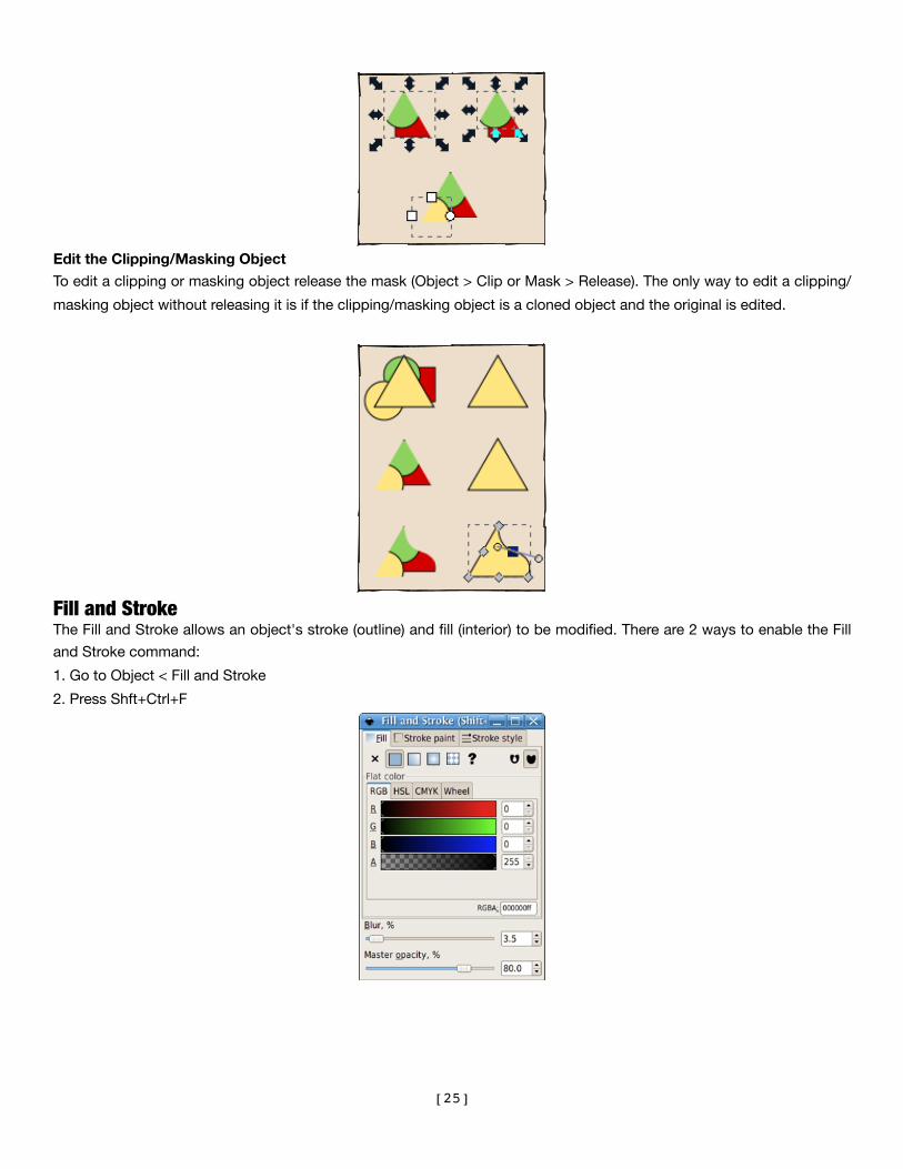
Edit the Clipping/Masking Object
To edit a clipping or masking object release the mask (Object > Clip or Mask > Release). The only way to edit a clipping/
masking object without releasing it is if the clipping/masking object is a cloned object and the original is edited.
Fill and StrokeThe Fill and Stroke allows an object's stroke (outline) and fill (interior) to be modified. There are 2 ways to enable the Fill
and Stroke command:
1. Go to Object < Fill and Stroke
2. Press Shft+Ctrl+F
[25]

Fill Tab
The Fill tab allows the fill (interior) of the selected object(s) to be edited. Using the buttons just below the tab, the types
of fill can be selected, including no fill (the button with the X), flat color fill, as well as linear or radial gradients. Further
below, a collection of color pickers can be seen, each in its own tab: RGB, CMYK, HSL, and Wheel. Perhaps the most
convenient is the Wheel picker, the triangle can be rotated to choose a hue on the wheel, and then select a shade of that
hue within the triangle. All color pickers contain a slider to set the alpha (opacity) of the selected object(s).
Stroke Paint Tab
The Stroke Paint tab allows the color and transparency of the stroke (outline) to be edited. Or the stroke of an object can
be removed (by clicking the button with the X).
Stroke Style Tab
The Stroke Style tab allows the width and other parameters of the stroke to be set.
LayersLayers are a type of object group within a document. As the name indicates, they are like stacked slices of the image
which can be stacked, arranged, added, and removed. In addition, layers can be locked and made invisible to ease
editing of objects within other layers of the document.
Layers can be very useful for several purposes:
• Arranging sets of objects by z-order (or stacking)
• Grouping objects which should be made visible/invisible or locked/unlocked together
• Setting background layers which are visible but not selectable
The Layers Widget on the Status Bar
The quickest and easiest way to work with layers is to use the layers widget on the Status Bar.
Once multiple layers have been created in a drawing, a layer can be easily selected from the box. The current layer from
this widget can also be hidden/unhidden or locked/unlocked.
The Layers Dialog
The Layers Dialog controls all layer functions - adding new layers, renaming, deleting, arranging, toggling visibility and
edit-locking, and setting Blend mode and opacity.
[26]
Blend Mode and Opacity
A Blend mode can be applied to layers, which makes all objects in a layer blend together as if they were one object (i.e.,
the two objects within the same layer will not blend with each other when layer blend modes are used). The available
modes are the common Multiply, Screen, Darken, and Lighten.
Opacity for an entire layer operates in a similar manner - objects within the layer have their opacity set as if they were a
single object, so that one will not show through the others. Only objects from layers beneath will show through the
affected layers.
How to Use
To open the Layers Dialog, press Ctrl+Shft+L or select Layer > Layers.
Adding Layers
New documents created by Inkscape using the default template have only one layer. It is simple to create new layers
which can be used right away.
To create a new layer, click "Create a new layer" on the Layers Dialog.
(Note: Although it is possible to have the same name for multiple layers (since each is given a different ID automatically),
this is not the SVG standard. It is good practice to name each layer differently.)
Renaming Layer
To rename a layer, double-click on the layer name in the Layers Dialog or right-click the layer and select Rename Layer.
Selecting Layers
To select a layer (to make it active), simply click on the layer once in the Layers dialog or select it from the layers widget
on the status bar.
Moving a Selection Between Layers
To move the current selection to the previous or next layer press Shift+PgUp or Shift+PgDn .
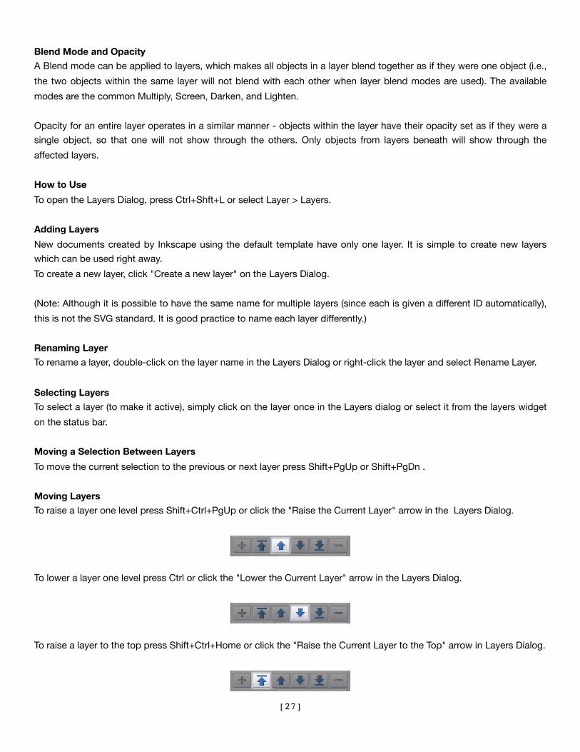
Moving Layers
To raise a layer one level press Shift+Ctrl+PgUp or click the "Raise the Current Layer" arrow in the Layers Dialog.
To lower a layer one level press Ctrl or click the "Lower the Current Layer" arrow in the Layers Dialog.
To raise a layer to the top press Shift+Ctrl+Home or click the "Raise the Current Layer to the Top" arrow in Layers Dialog.
[27]

To lower a layer to the bottom press Shift+Ctrl+End or click the "Lower the Current Layer to the Bottom" arrow in the
Layers Dialog.
Deleting Layers
To delete a layer, it must be selected. Click the "Delete the Current Layer" button in the Layers Dialog.
Locking Layers
To lock or unlock layers, click on the lock icon to the left of the layer name in the Layers dialog or the status bar. The icon
changes to reflect the current edit-lock status.
Hiding Layers
To make a layer invisible or visible, click on the eye icon to the left of the layer name in the Layers dialog or the status
bar. The icon changes to reflect the current visibility status.
Blend Mode
To change the blend mode, click on the Blend Mode drop-down in the Layers Dialog and select a new mode.
Opacity
To change the opacity of a layer, move the Opacity slider in the Layers Dialog to the right or left.
[28]

Text ToolThe Text Tool makes it possible to write text in a drawing.
How to use
To enable the Text Tool, press Shift+Ctrl+T. Alternatively, there is a Text menu which allows the aspect of the characters
or their behavior with respect to other elements of the drawing to be changed.
There are two ways to use the Text Tool:
1. Select the Text Tool and click on the canvas to create a simple line field. It will grow with the written text.
2. Select the Text Tool and then Click and drag to draw a rectangular text box. This rectangular frame will contain the
text and will be the limit for the word wrapping. The text box will not grow with the text. So if there is too much text
for the frame, some letters will simply not be displayed. This frame can be manually resized by dragging the handle
at the bottom right corner. The “Flow into Frame” command of the Text menu makes it easy to use any shape as a
text container.
Bitmap TracingImportant!
It is recommended that images be engraved in grayscale at 300 dpi. Grayscaling an image can be accomplished by
highlighting the image and then “Desaturating” it by selecting Filters < Color < Desaturate. The dpi can be set within the
Laser Cutter print setup.
Any images incorporated in the design will need to be traced. This can be accomplished by selecting the inserted image
and using the PATH > “Trace Bitmap” window. There are several tracing options:
Brightness Cutoff
This merely uses the sum of the red, green, and blue (or shades of gray) of a pixel as an indicator of whether it should be
considered black or white. The threshold can be set from 0.0 (white) to 1.0 (black). The higher the threshold setting, the
fewer pixels that will be considered white, and the intermediate image with become darker.
Edge Detection
This will produce an intermediate bitmap that will look less like the original image than the result of the Brightness Cutoff,
but it will likely provide curve information that would otherwise be ignored. The threshold setting here (0.0 – 1.0) adjusts
the brightness threshold of whether a pixel adjacent to a contrast edge will be included in the output. This setting can
adjust the darkness or thickness of the edge in the output.
[29]
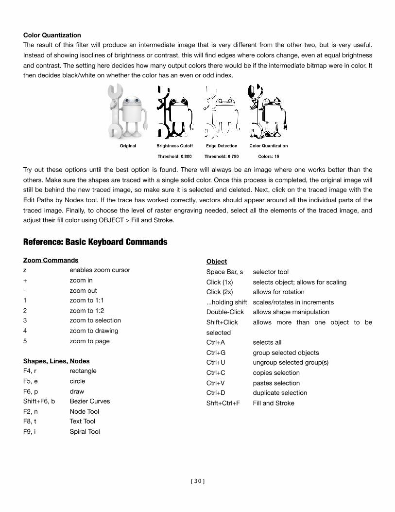
Color Quantization
The result of this filter will produce an intermediate image that is very different from the other two, but is very useful.
Instead of showing isoclines of brightness or contrast, this will find edges where colors change, even at equal brightness
and contrast. The setting here decides how many output colors there would be if the intermediate bitmap were in color. It
then decides black/white on whether the color has an even or odd index.
Try out these options until the best option is found. There will always be an image where one works better than the
others. Make sure the shapes are traced with a single solid color. Once this process is completed, the original image will
still be behind the new traced image, so make sure it is selected and deleted. Next, click on the traced image with the
Edit Paths by Nodes tool. If the trace has worked correctly, vectors should appear around all the individual parts of the
traced image. Finally, to choose the level of raster engraving needed, select all the elements of the traced image, and
adjust their fill color using OBJECT > Fill and Stroke.
Reference: Basic Keyboard Commands
Zoom Commands
z enables zoom cursor
+ zoom in
- zoom out
1 zoom to 1:1
2 zoom to 1:2
3 zoom to selection
4 zoom to drawing
5 zoom to page
Shapes, Lines, Nodes
F4, r rectangle
F5, e circle
F6, p draw
Shift+F6, b Bezier Curves
F2, n Node Tool
F8, t Text Tool
F9, i Spiral Tool
Object
Space Bar, s selector tool
Click (1x) selects object; allows for scaling
Click (2x) allows for rotation
...holding shift scales/rotates in increments
Double-Click allows shape manipulation
Shift+Click allows more than one object to be
selected
Ctrl+A selects all
Ctrl+G group selected objects
Ctrl+U ungroup selected group(s)
Ctrl+C copies selection
Ctrl+V pastes selection
Ctrl+D duplicate selection
Shft+Ctrl+F Fill and Stroke
[30]

APPENDIX 1: INKSCAPE (IMPORT/EXPORT FORMATS)
Adobe Illustrator (.ai)
Adobe Illustrator SVG (.ai.svg)
Bitmap (.bmp)
Corel Draw (.cdr, .ccx, .cdt, .cmx)
Computer Graphics Metafile (.cgm)
Windows Cursor (.cur)
AutoCAD (.dxf)
Encapsulated PostScript (.eps)
Gimp Gradient (.ggr)
Graphic Interchange Format (.gif)
Apple Icon Image Icon (.icns)
Windows Icon (.ico)
Joint Photographic Experts Group (.jpg, .jpe, .jpeg)
Portable Anymap (.pbm, .pgm, .pnm, .ppm)
Paintbrush Bitmap Format (.pcx)
Portable Network Graphic (.png)
HPGL File for Desktop Cutters (.plt)
sK1 Vector Graphics FIles (.sk1)
Scalable Vector Graphics (.svg)
Scalable Vector Graphics (compressed) (.svgz)
Truevision Advanced Raster Graphics Adapter (.tga, .targa)
Tagged Image Format (.tif, .tiff)
Text (.txt)
Wireless Application Protocol Bitmap Format (.wbmp)
Windows Meta File (.wmf)
Word Perfect Graphics (.wpg)
Microsoft Application eXtensible Markup Language) (.xaml)
X-BitMap (.xbm)
X-Pixmap (.xpm)
[31]

APPENDIX 2: TUTORIAL REFERENCES
This tutorial was adapted from:
Official Tutorials: http://inkscape.org/doc
Keys and Mouse References: http://inkscape.org/doc/keys046.html
[32]