27590639 free siemens nx unigraphics tutorial surface modeling
DESCRIPTION
ug nxTRANSCRIPT

Intellectual Technology LimitedProvide Expertise to Siemens NX Users in China and Hong KongSiemens NX 6 Surface Modeling - Mouse
Siemens NX 6 Surface-modeling (Tutorial 2 – Mouse)
Surface-modelingSolid-modelingAssembly DesignDesign with a Master ModelDesign in Context
Version 1a – Feb 2010 Copyright © 2010 by Intellectual Technology Limited Page 1

Intellectual Technology LimitedProvide Expertise to Siemens NX Users in China and Hong KongSiemens NX 6 Surface Modeling - Mouse
Tutorial 2A - Import 2D outline drawing into Siemens NX 6- Build 3D curves based on the imported drawing- Build the upper surfaces of the mouse
Tutorial 2B - Do the draft analysis to search any undercut portion on the upper surfaces- Build the lower surfaces of the mouse- Convert the surfaces into a solid (Master Model)
Tutorial 2C- Build the parting surfaces based on the imported drawing - Create components from the finished model- Create a new part in the assembly (Design in Context)- Modify a part design while looking at other parts (Design in Context)
Please be reminded that this series of tutorials is designed to demonstrate a design approach with Siemens NX, rather than the command itself. For the details of commands, please read the online help or attend the software training.
Version 1a – Feb 2010 Copyright © 2010 by Intellectual Technology Limited Page 2

Intellectual Technology LimitedProvide Expertise to Siemens NX Users in China and Hong KongSiemens NX 6 Surface Modeling - Mouse
Intellectual Technology Ltd is a regional value added reseller of Siemens PLM solutions. We enable our customers with innovative and collaborative design, engineering, manufacturing, simulation tools.
What ITL can do for you:1. Engineering Design & Developmenta. Conversion of 2D data into 3D modelb. Detailing and Drafting of products for manufacturing with tolerances and surface finishes, Assembly layout drawings
and BOM creationc. Reverse Engineering - Creation of accurate product models and detailed drawings using CMM and scanning techniques
2. NX Solution Traininga. NX Basic & Advanced Design trainingsb. NX CAM Programmer Trainingc. NX Mould Design/Electrode Designd. Other Customized training
3. NX CAM Post Processor DevelopmentWe provide services of post processor customization and development for the following machinesa. 3 Axis , 4 Axis and 5 Axis Millingb. Turning, EDM and Wire EDM
4. NX Solution Maintenance and SupportWe provide NX solution annual maintenance and support to our customers. This solution maintenance includes the following major services:a. Dedicated Application Engineer to Support the solution.b. On-site solution supportc. Solution upgrades, upgrade trainingsd. Free phone enquiries
Version 1a – Feb 2010 Copyright © 2010 by Intellectual Technology Limited Page 3
Intellectual Technology LimitedProvide Expertise to Siemens NX Users in China and Hong KongSiemens NX 6 Surface Modeling - Mouse
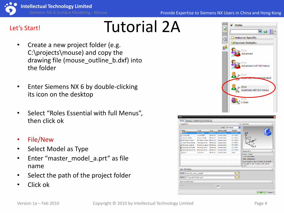
Tutorial 2A• Create a new project folder (e.g.
C:\projects\mouse) and copy the drawing file (mouse_outline_b.dxf) into the folder
• Enter Siemens NX 6 by double-clicking its icon on the desktop
• Select “Roles Essential with full Menus”, then click ok
• File/New
• Select Model as Type
• Enter “master_model_a.prt” as file name
• Select the path of the project folder
• Click ok
Version 1a – Feb 2010 Copyright © 2010 by Intellectual Technology Limited Page 4
Let’s Start!

Intellectual Technology LimitedProvide Expertise to Siemens NX Users in China and Hong KongSiemens NX 6 Surface Modeling - Mouse
Tutorial 2A• Double-click on the default Datum
coordinates system
• Select “Absolute CSYS” as type
• Click ok
To Import the outline drawing:-
• File/Import/DXF
• Select the file “mouse_outline_b.dxf”
• Select “WORK” as “Import to Part”
• Click ok
(the imported curves will be pasted on the XY plane)
Version 1a – Feb 2010 Copyright © 2010 by Intellectual Technology Limited Page 5
Double-click to edit

Intellectual Technology LimitedProvide Expertise to Siemens NX Users in China and Hong KongSiemens NX 6 Surface Modeling - Mouse
Tutorial 2ATo confirm that the size of the drawing is correct:-
• Double-click on the scale line of the drawing
• Check if the displayed length is 50mm; if not, we need to enlarge or shrink the drawing into the correct size
• Delete the scale line ( we don’t need it anymore)
To Reposition the 3 views (offset from absolute datum by 150mm):-
• Edit/Move Objects…
• Select all the curves of Top View
• Select “Move Handle Only”
• Drag the handle to the midpoint of the arc
• Deselect “move handle only”
• Select “Move Original”
• Enter x =0. y=0, z=150
• then rotate about z by 90deg (clockwise)
• Click “Apply”
Version 1a – Feb 2010 Copyright © 2010 by Intellectual Technology Limited Page 6
Handle (free to move)

Intellectual Technology LimitedProvide Expertise to Siemens NX Users in China and Hong KongSiemens NX 6 Surface Modeling - Mouse
Tutorial 2A• Select all curves of Front View• Select “Move Handles Only” • Draft the handle to the midpoint of the line• Deselect “move handles only”• Enter x =0, y= -150, z=0• Then rotate about x by 90deg (as shown )• Click apply
• Select all curves of Right View• Select “Move Handles Only” • Draft the handle to the endpoint of the line
• Deselect “move handles only”• Enter x =150, y= 2.85, z=0• Then rotate about x by 90deg (as shown )• Rotate about z by 90deg (as shown )• Click ok to complete
Version 1a – Feb 2010 Copyright © 2010 by Intellectual Technology Limited Page 7
Result
Top View
Right View
Front View
Intellectual Technology LimitedProvide Expertise to Siemens NX Users in China and Hong KongSiemens NX 6 Surface Modeling - Mouse
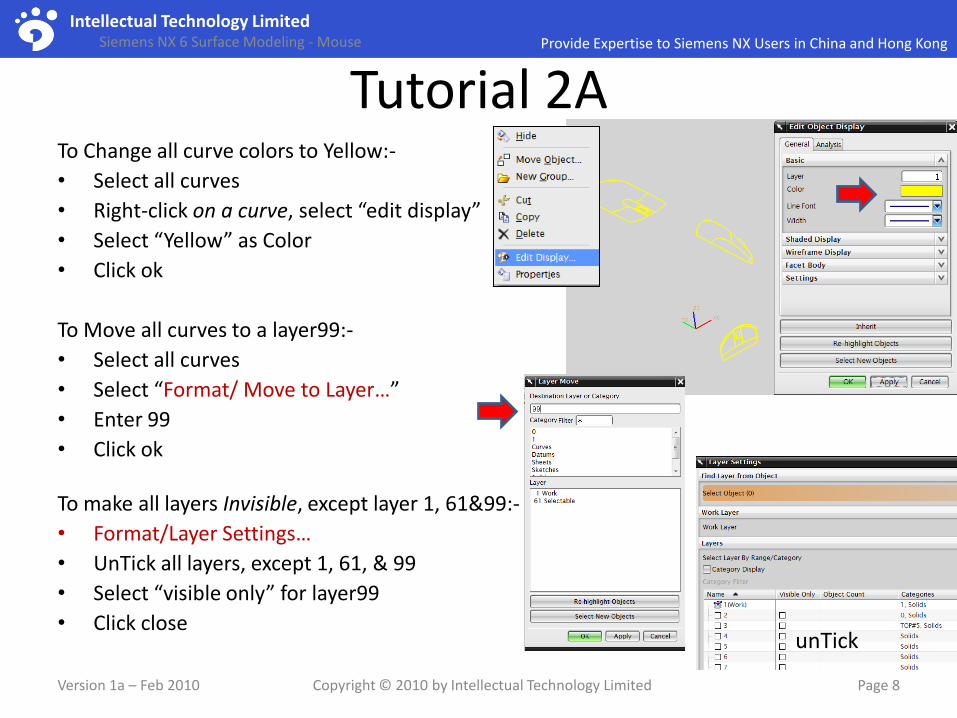
Tutorial 2ATo Change all curve colors to Yellow:-
• Select all curves
• Right-click on a curve, select “edit display”
• Select “Yellow” as Color
• Click ok
To Move all curves to a layer99:-
• Select all curves
• Select “Format/ Move to Layer…”
• Enter 99
• Click ok
To make all layers Invisible, except layer 1, 61&99:-
• Format/Layer Settings…
• UnTick all layers, except 1, 61, & 99
• Select “visible only” for layer99
• Click close
Version 1a – Feb 2010 Copyright © 2010 by Intellectual Technology Limited Page 8
unTick

Intellectual Technology LimitedProvide Expertise to Siemens NX Users in China and Hong KongSiemens NX 6 Surface Modeling - Mouse
Tutorial 2A• Insert Datum/Datum plane
• Select xy plane
• Distance 50mm
• Click ok
• Insert/Sketch…
• Select the offset plane
• Click ok
• Draw a point as shown
• Mirror the point around y axis
• Draw a 3-point arc (start & end at the existing points, middle at the origin)
• Drag the endpoint to make it longer
• (the arc should match the reference)
• Click icon “Finish Sketch”
Version 1a – Feb 2010 Copyright © 2010 by Intellectual Technology Limited Page 9
Draw a point here
Mirrored point

Intellectual Technology LimitedProvide Expertise to Siemens NX Users in China and Hong KongSiemens NX 6 Surface Modeling - Mouse
Tutorial 2A• Insert Datum/Datum plane
• Select xz plane
• Reverse Direction
• Distance 50mm
• Click ok
• Insert/Sketch…
• Select the offset plane
• Click ok
• Draw a point as shown
• Mirror the point around z axis
• Draw a 3-point arc (start & end at the existing points, middle on the yellow arc)
• Drag on the curve to adjust radius
• Drag an endpoint to make it longer
• Click icon “Finish Sketch”
Version 1a – Feb 2010 Copyright © 2010 by Intellectual Technology Limited Page 10
drag
drag

Intellectual Technology LimitedProvide Expertise to Siemens NX Users in China and Hong KongSiemens NX 6 Surface Modeling - Mouse
Tutorial 2ATo build a 3d curve by combined projection :-
• Insert/ Curve from Curves/ Combined Projection
• Select sketch.0 as curve.1
• Select sketch.1 as curve.2
• (projection direction = normal to curve)
• Click ok
• Hide Sketch.0 & Sketch.1 (right-click, select “hide”)
• Hide Plane1 & Plane2
(This combined curve can fit the shapes of both top view and front view)
Version 1a – Feb 2010 Copyright © 2010 by Intellectual Technology Limited Page 11
Sketch.0
Sketch.1

Intellectual Technology LimitedProvide Expertise to Siemens NX Users in China and Hong KongSiemens NX 6 Surface Modeling - Mouse
Tutorial 2A• Insert/Datum/Datum plane• Select yz plane• Switch to Top View• Drag the plane onto the plane (we can drag
the green ball to make the plane bigger)• (offset value = 30.5)• Click ok
• Insert/Sketch• Select the offset plane, click ok• Draw two arcs (tangent to each other)• Click icon “Constraints”• Select the end point and the absolute y axis• Select “point on curve” (the endpoint is now
on y-axis)• Adjust the shape & position of the arcs so that
they can match the yellow reference• Click icon “finish sketch”
Version 1a – Feb 2010 Copyright © 2010 by Intellectual Technology Limited Page 12
drag

Intellectual Technology LimitedProvide Expertise to Siemens NX Users in China and Hong KongSiemens NX 6 Surface Modeling - Mouse
Tutorial 2ATo Create an extruded surface:-
• Insert/Design Feature/Extrude…
• Select the combined curve as Section
• Select +Z as the direction
• Enter 20 mm as distance
• Click ok
To Create a Draft 5 deg (from parting line):-
• Insert/Detail Feature/Draft
• Select “From Edges” as type
• Select +Z as Draw Direction
• Select the lower edge
• Enter 5 deg as Angle 1
• Click ok
Version 1a – Feb 2010 Copyright © 2010 by Intellectual Technology Limited Page 13

Intellectual Technology LimitedProvide Expertise to Siemens NX Users in China and Hong KongSiemens NX 6 Surface Modeling - Mouse
Tutorial 2ATo Create an extruded surface with Draft:-
• Insert/Design Feature/Extrude
• Select “Sketch.2” as Section
• Select +Z as the direction
• Enter 20 mm as distance
• Select “From Start Limit” as Draft
• Enter 5 deg as Angle
• Click ok
To Mirror a surface:-
• Insert/Associative Copy/Mirror Body
• Select this surface as body
• Select yz plane as mirror plane
• Click ok
Version 1a – Feb 2010 Copyright © 2010 by Intellectual Technology Limited Page 14
result

Intellectual Technology LimitedProvide Expertise to Siemens NX Users in China and Hong KongSiemens NX 6 Surface Modeling - Mouse
Tutorial 2A• Insert/Detailed Feature/Face Blend
• Select surface as Chain1
• Select surface as Chain2
• (Both arrows should point inward; if not, reverse it)
• Enter 5mm as Radius
• Select “Trim to all input faces”
• Click ok
• Repeat the above steps for the opposite side
Version 1a – Feb 2010 Copyright © 2010 by Intellectual Technology Limited Page 15
result

Intellectual Technology LimitedProvide Expertise to Siemens NX Users in China and Hong KongSiemens NX 6 Surface Modeling - Mouse
Tutorial 2A• Hide Datum.3
• Insert/Sketch
• Select XZ plane, click ok
• Insert/ Curve from Curves/Offset from curve
• Select the combined curve
• 3.5 mm as offset value
• Click ok
• (We can create an offset curve from any entity that is out of the sketch.)
• Click icon “Finish Sketch”
Version 1a – Feb 2010 Copyright © 2010 by Intellectual Technology Limited Page 16

Intellectual Technology LimitedProvide Expertise to Siemens NX Users in China and Hong KongSiemens NX 6 Surface Modeling - Mouse
Tutorial 2ATo create a sketch mating with an external sketch:-
• Insert/Sketch
• Select yz plane
• Draw two arcs as shown (tangent to each other)
• Draw a horizontal line starting from the connecting point , then make either one tangent to it; Convert the line to a reference line
• Create an intersection point on the offset curve (Insert/Curve-from-curves/intersection point)
• Make a “Point on curve” constraint
• Adjust the shape & position of the arcs so that they can match the yellow reference (just dragon curves or points)
• Click icon “finish sketch”
Version 1a – Feb 2010 Copyright © 2010 by Intellectual Technology Limited Page 17
Offset curve
Horizontal line(reference)
Coincided with y axis

Intellectual Technology LimitedProvide Expertise to Siemens NX Users in China and Hong KongSiemens NX 6 Surface Modeling - Mouse
Tutorial 2A• Insert/Datum/Datum plane
• Select XZ plane
• Select the endpoint
• Select “Associative”
• Click ok
• Insert/Sketch
• Select the offset plane, click ok
• Draw a point as shown
• Mirror the point around Z axis
• Draw a 3-point arc (start & end at the two points, middle at the point )
• Drag on the curve to adjust radius
• Drag the endpoint to make it longer
• Click icon “Finish Sketch”
Version 1a – Feb 2010 Copyright © 2010 by Intellectual Technology Limited Page 18

Intellectual Technology LimitedProvide Expertise to Siemens NX Users in China and Hong KongSiemens NX 6 Surface Modeling - Mouse
Tutorial 2ATo Create a Swept surface ( 1section & 2
guides):-
• Insert/Sweep/Swept
• Select “Single Curve” on selection filter
• Select Curve as Section
• Select Curve as Guide 1
• Click “Add new set”
• Select Curve as Guide 2
• Click ok
• Insert/Trim/Trim-and-Extend
• Select “Make Corner” as type
• Select a surface as Target
• Select the other surface as Tool
• Reverse arrows so that the result is as shown
• Click ok
Version 1a – Feb 2010 Copyright © 2010 by Intellectual Technology Limited Page 19

Intellectual Technology LimitedProvide Expertise to Siemens NX Users in China and Hong KongSiemens NX 6 Surface Modeling - Mouse
Tutorial 2A• Insert/Trim/Trim body
• Select the surface as Target
• Select Plane as Tool
• (arrow should point backward; if not, reverse it)
• Click ok
• Insert/Detail-Feature/Edge Blend
• Select an edge (all tangent edges are selected automatically; selection filter = tangent curves)
• Specify four points as variable radius points
• Enter values as shown
• Click ok
Version 1a – Feb 2010 Copyright © 2010 by Intellectual Technology Limited Page 20
7mm
7mm
3mm
3mm

Intellectual Technology LimitedProvide Expertise to Siemens NX Users in China and Hong KongSiemens NX 6 Surface Modeling - Mouse
Tutorial 2A• Draw one horizontal line at point
(Insert/Curve/Line , select “associative”)
• Draw one vertical line at point
• Insert/ Curve-from-Curves/Bridge
• Select horizontal line as start object
• Select vertical line as end object
• Select G1 (tangent) as start
• Select G1 (tangent) as end
• Select “Associative”
• Orient View to Top View
• Drag the arrows to match the yellow reference
• Click ok
Version 1a – Feb 2010 Copyright © 2010 by Intellectual Technology Limited Page 21
Intellectual Technology LimitedProvide Expertise to Siemens NX Users in China and Hong KongSiemens NX 6 Surface Modeling - Mouse
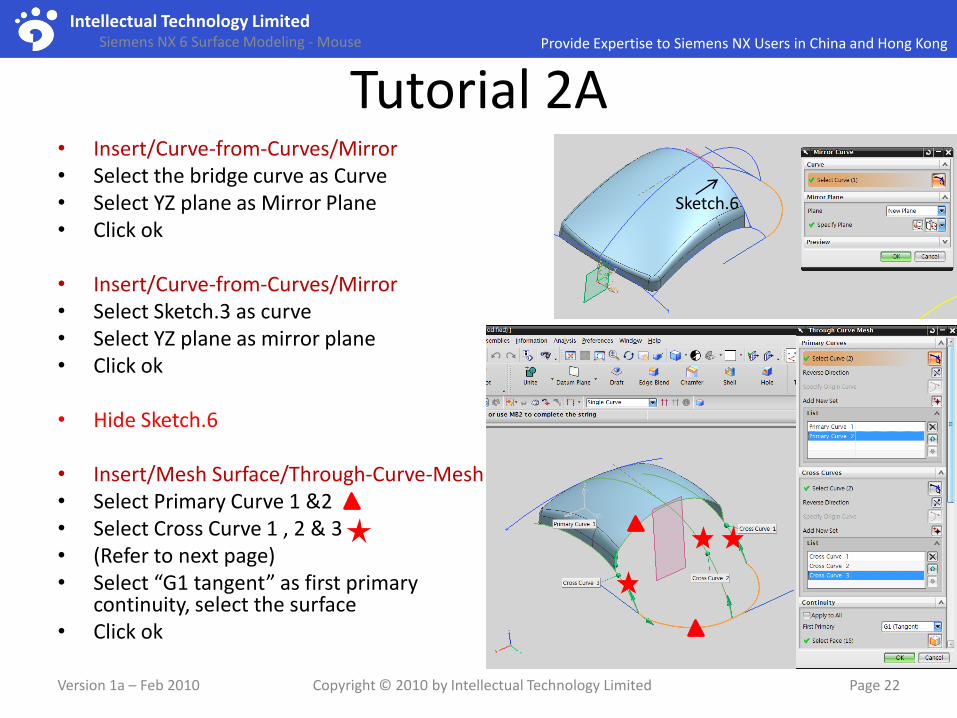
Tutorial 2A• Insert/Curve-from-Curves/Mirror• Select the bridge curve as Curve• Select YZ plane as Mirror Plane• Click ok
• Insert/Curve-from-Curves/Mirror• Select Sketch.3 as curve• Select YZ plane as mirror plane• Click ok
• Hide Sketch.6
• Insert/Mesh Surface/Through-Curve-Mesh• Select Primary Curve 1 &2• Select Cross Curve 1 , 2 & 3• (Refer to next page)• Select “G1 tangent” as first primary
continuity, select the surface• Click ok
Version 1a – Feb 2010 Copyright © 2010 by Intellectual Technology Limited Page 22
Sketch.6

Intellectual Technology LimitedProvide Expertise to Siemens NX Users in China and Hong KongSiemens NX 6 Surface Modeling - Mouse
Tutorial 2A
Version 1a – Feb 2010 Copyright © 2010 by Intellectual Technology Limited Page 23
2 Primary Curves
Primary curve1
Primary curve 2
Selection filter = Tangent curvesSelect an edge of Primary curve1Add New Set
Selection filter = Single CurvesSelect the two arcs of Primary curve 2(Arrow direction same as Curve1)Add New set
3 Cross Curves
File/Save

Intellectual Technology LimitedProvide Expertise to Siemens NX Users in China and Hong KongSiemens NX 6 Surface Modeling - Mouse
Tutorial 2A
Version 1a – Feb 2010 Copyright © 2010 by Intellectual Technology Limited Page 24
To Check if the whole skin can meet the required shape…
• Orient view to Top View
• Check
• Orient view to Front View
• Check
• Orient view to Right View
• Check
• File/ Save
Take a Rest!

Intellectual Technology LimitedBusiness Intelligence for Every one
What is Business Intelligence?Business Intelligence (BI) is a practice that employs collection, integration, analysis, interpretation and presentation of business information to help a corporation to better understand the market behavior and business context, thus assisting decision making.
Combined with Microsoft SQL server and its Analysis services, “Strategy Companion Analyzer 2007” allows non-technical business users to perform interactive analysis and easily create new reports and dashboards featuring a variety of components such as pivot tables, charts, web pages, scorecards, and more. These eye-catching visualizations allow users to easily see business results and trends, allowing them to take immediate action to improve performance.
Advantages of Analyzer 2007:
• Easy to Deploy
• Easy to Use
• Low Total Costs
Analyzer is being used successfully within a variety of industries such as banking, finance,
technology services, manufacturing, real estate, healthcare, insurance and others. The examples
are CITI, Loreal, Bosch, Johnson & Johnson, and 7-Eleven.
http://www.itltechnology.com/analyzer01.html
Copyright © 2010 by Intellectual Technology Limited Page 25
<advertisement>
Intellectual Technology LimitedProvide Expertise to Siemens NX Users in China and Hong KongSiemens NX 6 Surface Modeling - Mouse
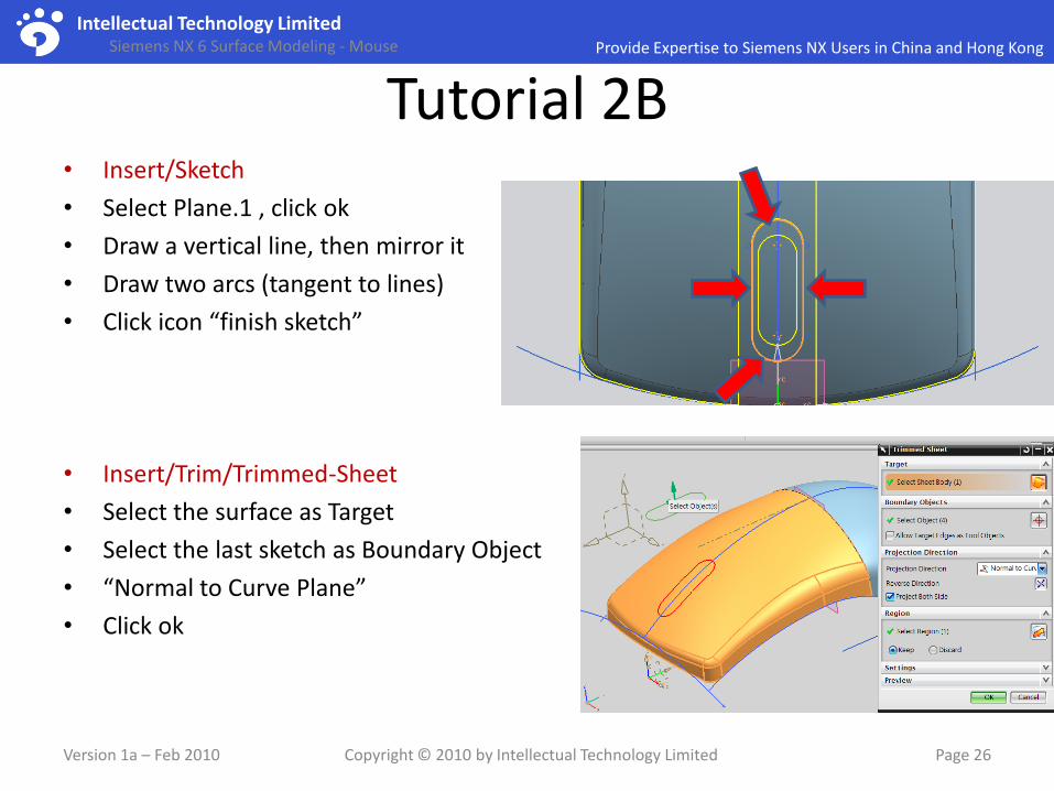
Tutorial 2B• Insert/Sketch
• Select Plane.1 , click ok
• Draw a vertical line, then mirror it
• Draw two arcs (tangent to lines)
• Click icon “finish sketch”
• Insert/Trim/Trimmed-Sheet
• Select the surface as Target
• Select the last sketch as Boundary Object
• “Normal to Curve Plane”
• Click ok
Version 1a – Feb 2010 Copyright © 2010 by Intellectual Technology Limited Page 26

Intellectual Technology LimitedProvide Expertise to Siemens NX Users in China and Hong KongSiemens NX 6 Surface Modeling - Mouse
Tutorial 2B• Insert/Mesh Surface/Sections…
• Select “Two Point Radius” as Type
• Select Start guide
• Select End guide
• Select Spine curve
• Law type = Constant
• Value = 5mm
• Click ok
• Insert/Mesh surface/Through Curves
• Select section1
• Select section2
• Select G2 curvature as First section continuity
• Select the last surface
• Select G0 curvature as last section continuity
• Flow direction = Perpendicular
• Click ok
• Repeat the above steps to close another opening
Version 1a – Feb 2010 Copyright © 2010 by Intellectual Technology Limited Page 27

Intellectual Technology LimitedProvide Expertise to Siemens NX Users in China and Hong KongSiemens NX 6 Surface Modeling - Mouse
Tutorial 2B• Insert/ Combine Bodies/ Sew
• Select the biggest surface as Target
• Select other surfaces as Tool
• Click ok
• Analysis/Shape/Draft
• Change draft angle to 3 deg
• An error is found (not enough 3 deg)
• Double-click the line
• Add 10 deg
• The bridge curve will be updated (if it is associative)
• (If you forgot to make the bridge curve “associative”, double-click to edit, drag the end point out and snap onto the endpoint of the line again, select G2.)
• Do Draft analysis again to see if the error is corrected.
Version 1a – Feb 2010 Copyright © 2010 by Intellectual Technology Limited Page 28
undercut

Intellectual Technology LimitedProvide Expertise to Siemens NX Users in China and Hong KongSiemens NX 6 Surface Modeling - Mouse
Tutorial 2BWe are going to build a lower skin…
• Insert/Design Feature/Extrude
• Select the curve
• Enter -20mm as End Limit distance
• Click ok
• Insert/Design Feature/Draft
• Select “From edges” as type
• Select +z as Draw Direction
• Select the top edge
• Orient View to Right View
• Drag the draft angle to 10 deg (to match the Yellow reference)
• Click ok
Version 1a – Feb 2010 Copyright © 2010 by Intellectual Technology Limited Page 29
drag

Intellectual Technology LimitedProvide Expertise to Siemens NX Users in China and Hong KongSiemens NX 6 Surface Modeling - Mouse
Tutorial 2B• Insert/Flange Surface/Law Extension
• Select the sketch as base profile
• Select –Z as reference vector
• Length law = constant, 30mm
• Select “Linear” as Angle Law type
• Start = 10 deg, End = 2 deg
• Click ok
• Insert/Associative Copy/Mirror Body
• Select the surface
• Select yz plane as mirror plane
• Click ok
Version 1a – Feb 2010 Copyright © 2010 by Intellectual Technology Limited Page 30
start
end

Intellectual Technology LimitedProvide Expertise to Siemens NX Users in China and Hong KongSiemens NX 6 Surface Modeling - Mouse
Tutorial 2B• Insert/Detail Feature/Face Blend
• Select surface as Chain1
• Select surface as Chain2
• (Both arrows should point inward; if not, reverse it)
• Enter 4.5mm as Radius
• Select “Trim to all input faces”
• Click ok
• Repeat the above steps for the opposite side
Version 1a – Feb 2010 Copyright © 2010 by Intellectual Technology Limited Page 31

Intellectual Technology LimitedProvide Expertise to Siemens NX Users in China and Hong KongSiemens NX 6 Surface Modeling - Mouse
Tutorial 2B• Insert/Curve/Line
• Select the origin as start point
• Select any point on x-axis
• Enter -50mm as start limit
• Enter 50 mm as end limit
• Click ok
• Insert/Design Feature/Extrude
• Select the line as section
• Select y as direction
• Drag the handle to define the length, longer than the model
• Click ok
• Insert/Combine Bodies/Sew
• Select all surfaces, except the last extruded surface
• Click ok
Version 1a – Feb 2010 Copyright © 2010 by Intellectual Technology Limited Page 32

Intellectual Technology LimitedProvide Expertise to Siemens NX Users in China and Hong KongSiemens NX 6 Surface Modeling - Mouse
Tutorial 2B• Insert/Trim/Trim-and-Extend
• Select “Make Corner” as type
• Select Target surface
• Select Tool surface
• Reverse arrows so that the result is as shown
• Click ok
To check if the solid can be created:-
• Right-click “Name”, deselect “Timestamp order”
• One Sheet Body is found, but not a solid!
Version 1a – Feb 2010 Copyright © 2010 by Intellectual Technology Limited Page 33

Intellectual Technology LimitedProvide Expertise to Siemens NX Users in China and Hong KongSiemens NX 6 Surface Modeling - Mouse
Tutorial 2BTo find out the surface gaps that lead to the
failure of surface-to-solid conversion:-
• Insert/Offset-Scale/Sheets-to-Solid-assistant
• Enter 0mm as First Offset & Second Offset
• Select the surface
• Click Apply
• Select “Show Sheet Boundary” (two gaps are found)
• Click Cancel
• Right-click “Name”, select “Timestamp order”
• Double-click to edit the last SEW feature on tree
• Increase Tolerance from 0.025 to 0.05
• Click ok (Now a solid can be created)
Version 1a – Feb 2010 Copyright © 2010 by Intellectual Technology Limited Page 34

Intellectual Technology LimitedProvide Expertise to Siemens NX Users in China and Hong KongSiemens NX 6 Surface Modeling - Mouse
Tutorial 2B• Insert/ Design Feature/Edge Blend• Select the edge• Enter 1mm as radius • Click ok
• Insert/Offset-Scale/Shell• Select “Shell all Faces” as type• Select the solid• (arrow should point inward)• Enter 2.5mm as thickness• Click ok
• Show all sketches/curves/ datums
• Move all sketches/curves to Layer 41• Move all offset datum planes to Layer 61
• File/Save
Version 1a – Feb 2010 Copyright © 2010 by Intellectual Technology Limited Page 35
Take a Break!

Intellectual Technology LimitedCMS IntelliCAD - the Best DWG Alternative
CMS IntelliCAD- Low Cost Professional Drawing Software (made by USA)- Fully Support AutoCAD 2.5 - 2009 files- Very low promotion price - just HK$368/ US$47.3 (Personal Standard edition) - Traditional Chinese/ English user interface- AutoCAD users needn't learn again. It uses nearly the same AutoCAD operations & commands (including shortcut keys); AutoCAD and CMS IntelliCAD files are interchangeable.- 15 days Free Trial
Minimum system requirements:
• Supported OS: Windows XP / VISTA / 7 | 32-bit & 64-bit
• HD 130Mb | RAM 64Mb
http://www.itltechnology.com/cms01.html
Copyright © 2010 by Intellectual Technology Limited Page 36
Try it Now!
<advertisement>

Intellectual Technology LimitedProvide Expertise to Siemens NX Users in China and Hong KongSiemens NX 6 Surface Modeling - Mouse
Tutorial 2CWe’ve built the overall shape of the mouse. Now, we
are going to create parting surfaces, and then split the master model into separate components.
Check Top View
Check Front View
Check Right View
(the model should match the three reference views)
Version 1a – Feb 2010 Copyright © 2010 by Intellectual Technology Limited Page 37

Intellectual Technology LimitedProvide Expertise to Siemens NX Users in China and Hong KongSiemens NX 6 Surface Modeling - Mouse
Tutorial 2C• Make Layer 41 visible
• Insert/Sweep/ Swept
• Select Section curve
• Select Guide curve
• Select “Anywhere along guide” as section location
• Click ok
• Insert/Design Feature/Extrude
• Select the two surface edges
• Select +z value as direction
• Enter 3 mm as start limit, -10mm as end limit
• Click ok
• Insert/Offset Scale/Offset Face
• Select the extrude surface
• Enter 2.5mm as offset (arrow pointing inward)
• Click ok
Version 1a – Feb 2010 Copyright © 2010 by Intellectual Technology Limited Page 38
guide
section

Intellectual Technology LimitedProvide Expertise to Siemens NX Users in China and Hong KongSiemens NX 6 Surface Modeling - Mouse
Tutorial 2C• Insert/Trim/Trim-and-Extend
• Select “By Distance” as type
• Select the surface edges
• Enter 10mm as extension
• Click ok
Hide the solid body
• Draw a line (from point to point); select associative
• Insert/Mesh Surface/N-sided Surface
• Select the line & the edges
• Click ok
Version 1a – Feb 2010 Copyright © 2010 by Intellectual Technology Limited Page 39

Intellectual Technology LimitedProvide Expertise to Siemens NX Users in China and Hong KongSiemens NX 6 Surface Modeling - Mouse
Tutorial 2C• Insert/Trim/Trim-and-Extend
• Select the surface edge
• Enter 20mm as extension
• Click ok
• Insert/Combine Bodies/Sew
• Select the two surfaces
• Click ok
• Insert/Trim/Trim-and-Extend
• Select “Make Corner” as type
• Select Target surface
• Select Tool surface
• Reverse arrows so that the result is as shown
• Click ok
Version 1a – Feb 2010 Copyright © 2010 by Intellectual Technology Limited Page 40
result
Intellectual Technology LimitedProvide Expertise to Siemens NX Users in China and Hong KongSiemens NX 6 Surface Modeling - Mouse
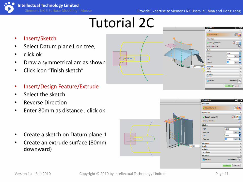
Tutorial 2C• Insert/Sketch
• Select Datum plane1 on tree,
• click ok
• Draw a symmetrical arc as shown
• Click icon “finish sketch”
• Insert/Design Feature/Extrude
• Select the sketch
• Reverse Direction
• Enter 80mm as distance , click ok.
• Create a sketch on Datum plane 1
• Create an extrude surface (80mm downward)
Version 1a – Feb 2010 Copyright © 2010 by Intellectual Technology Limited Page 41

Intellectual Technology LimitedProvide Expertise to Siemens NX Users in China and Hong KongSiemens NX 6 Surface Modeling - Mouse
Tutorial 2C• Show the Solid
• Format/Layer settings
• Make layer 41 (curves) invisible
• Make layer 61 (datums) invisible
• Select all remaining curves/sketches
• Format/Move to Layer
• Move them to layer 42
• File Save
• File/New/Assembly
• Enter “Mouse_assembly_a.prt” as file name; in the same project folder
• Click ok
• Select “master_model_a.prt” on the list
• Select “Absolute Origin” as Positioning
Version 1a – Feb 2010 Copyright © 2010 by Intellectual Technology Limited Page 42

Intellectual Technology LimitedProvide Expertise to Siemens NX Users in China and Hong KongSiemens NX 6 Surface Modeling - Mouse
Tutorial 2CWe are going to split the Master Model into
separate parts (part files)…
The outlook of the mouse is controlled by the Master Model. If we make any change on it, the linked parts will be updated automatically. Also, because all components are created from one model, their surfaces & boundaries can always match among themselves when assembled together.
Version 1a – Feb 2010 Copyright © 2010 by Intellectual Technology Limited Page 43
With Link

Intellectual Technology LimitedProvide Expertise to Siemens NX Users in China and Hong KongSiemens NX 6 Surface Modeling - Mouse
Tutorial 2CTo Create Upper Body:-
• Assemblies/Components/Create New Component
• Select “model” as type
• Enter “upper_body_a.prt” as filename
• Click ok, click ok
• Double-click Upper_body on tree (Jump into part level from assembly level)
• Insert/Associative Copy/WAVE geometry linker
• Select the solid & three surfaces
• Click ok
• Hide master model (untick it on tree)
• Insert/Trim/Trim Body (3 times) to get this shape
• Move all surfaces to Layer 11
• Hide all layers except layer 1
Version 1a – Feb 2010 Copyright © 2010 by Intellectual Technology Limited Page 44

Intellectual Technology LimitedProvide Expertise to Siemens NX Users in China and Hong KongSiemens NX 6 Surface Modeling - Mouse
Tutorial 2CTo Create Right Button:-
• Double-click mouse_assembly (Jump into assembly level from part level)
• Hide (unTick on tree) Upper Body
• Show (Tick on tree) mastermodel
• Create a new component (refer to previous steps)
• Enter ”right_button_a.prt” as filename
• Copy the solid & parting surfaces from master model
• Hide mastermodel
• Create an Offset Surface (one face only) (0.5mm)
• Offset face (1mm, forward)
• Offset face (1mm, upward)
• Do 3 Trims
• Move all surfaces to Layer 11
Version 1a – Feb 2010 Copyright © 2010 by Intellectual Technology Limited Page 45

Intellectual Technology LimitedProvide Expertise to Siemens NX Users in China and Hong KongSiemens NX 6 Surface Modeling - Mouse
Tutorial 2CTo Create Left Button:-
• Double-click mouse_assembly• Hide other component• Show mastermodel
• Create a new component• Enter “left_button_a.prt” as filename• Copy the solid & parting surfaces from
master model• Hide mastermodel
• Offset Surface (one face only) (0.5mm)• Offset face (1mm)• Offset face (1mm)
• Do 3 Trims• Move all surfaces to Layer 11
Version 1a – Feb 2010 Copyright © 2010 by Intellectual Technology Limited Page 46

Intellectual Technology LimitedProvide Expertise to Siemens NX Users in China and Hong KongSiemens NX 6 Surface Modeling - Mouse
Tutorial 2CTo Create Middle Button:-
• Double-click mouse_assembly
• Hide other component
• Show mastermodel
• Create a new component
• Enter “middle_button_a.prt” as filename
• Copy the solid & parting surfaces from master model
• Hide mastermodel
• Do 2 trims
• Move all surfaces to Layer 11
Version 1a – Feb 2010 Copyright © 2010 by Intellectual Technology Limited Page 47

Intellectual Technology LimitedProvide Expertise to Siemens NX Users in China and Hong KongSiemens NX 6 Surface Modeling - Mouse
Tutorial 2CTo Create Lower Body:-
• Double-click mouse_assembly
• Hide other component
• Show mastermodel
• Create a new component
• Save it as “middle_button_a.prt”
• Copy the solid & parting surfaces from master model
• Hide mastermodel
• Offset face (0.5mm, downward)
• Trim body
• Move all surfaces to Layer 11
Version 1a – Feb 2010 Copyright © 2010 by Intellectual Technology Limited Page 48

Intellectual Technology LimitedProvide Expertise to Siemens NX Users in China and Hong KongSiemens NX 6 Surface Modeling - Mouse
Tutorial 2CTo Create a Wheel (New Part):-
• Double-click mouse_assembly• Show all components, except mastermodel
• Create a new component• Enter “wheel_a.prt” as filename
• Double-click wheel_a• Insert/Sketch• Select yz plane (zoom in to view), click ok• Draw a circle at origin (dia 20mm )• Click “finish sketch”
• Insert/Design feature/Extrude• Select the sketch• Enter 3mm as start, -3mm as end• Click ok
• Add Edge Blends 2mm• Move sketch to layer 21
Version 1a – Feb 2010 Copyright © 2010 by Intellectual Technology Limited Page 49

Intellectual Technology LimitedProvide Expertise to Siemens NX Users in China and Hong KongSiemens NX 6 Surface Modeling - Mouse
Tutorial 2C• Double-click mouse_assembly
• Assemblies/Components/Move component
• Select Wheel model
• Click “specify orientation” on the command menu
• Drag the wheel to the correct position
• Switch to top view, the wheel is nearly in the middle of the slot
• Switch to right view, the wheel position is roughly as shown
Version 1a – Feb 2010 Copyright © 2010 by Intellectual Technology Limited Page 50

Intellectual Technology LimitedProvide Expertise to Siemens NX Users in China and Hong KongSiemens NX 6 Surface Modeling - Mouse
Tutorial 2C
• Double-click middle_button_a
• Insert/Sketch• Select xy plane• Draw a profile slightly bigger than the
wheel• Click icon “finish sketch”
• Insert/Design Feature/Extrude• Select the sketch• Select “symmetric value” as limits• Enter 100mm• Select “Subtract”, select the solid• Click ok
• Double-click “mouse_assembly” on tree
• File/Save allVersion 1a – Feb 2010 Copyright © 2010 by Intellectual Technology Limited Page 51
“Design in Context” – make a design change while looking at other parts

Intellectual Technology LimitedProvide Expertise to Siemens NX Users in China and Hong KongSiemens NX 6 Surface Modeling - Mouse
Tutorial 2C• Click tab page “System materials” on the
left• Apply material texture one by one (just
drag and drop)• Upperbody, leftbutton & rightbutton
(aluminium)• Middle button & wheel (plastic black)• Lowerbody (plastic shiny resin red)
• Double-click any material on list, then we can see “Materials in part”
• Edit “Plastic Black”, change roughness to 0.05
• View/Perspective
• View/Visualization/High-Quality-Image• Click icon “basic scene editor”• Deselect “Use Image based lighting”• Start Shade, then save it as tif
Version 1a – Feb 2010 Copyright © 2010 by Intellectual Technology Limited Page 52Finished! Well Done!
Drag & drop

www.itltechnology.com Customer Oriented, On-site Support
ITLConsulting | Sales | Technical Support
Key Differentiators- Our employees are motivated to guarantee 100% customer satisfaction;
- Our consultants have successfully served over 100 clients;
- We can provide product expertise, a deep understanding of your industry, and value that extends beyond your software purchase;
- Special team to focus on high value-added services such as design problem-solving and customization of CAM post-processors;
- Good services and support to accelerate return on investment and optimize productivity;
- Good relationship with local universities to support R&D of customers.