27 recording and playing video - hmisource.com · 27 recording and playing video ... 27.5 playing...
TRANSCRIPT

27-1
27 Recording and Playing Video
This chapter explains how to use GP-Pro EX to record and play videos, and explains displaying video using Image Units (optional) such as the VM unit or DVI unit and other useful features. Please start by reading "27.1 Settings Menu" (page 27-2) and then turn to the corresponding page.
27.1 Settings Menu ...............................................................................................27-227.2 Displaying Video Camera Output..................................................................27-827.3 Recording Video..........................................................................................27-1227.4 Recording Video Before and After a Malfunction ........................................27-2027.5 Playing Movies ............................................................................................27-2427.6 Displaying Multiple Video Camera Outputs Simultaneously .......................27-5227.7 Displaying PC Screen .................................................................................27-6027.8 Saving Video Output as Still Images ...........................................................27-6627.9 Settings Guide.............................................................................................27-7327.10 Restrictions ...............................................................................................27-150

Settings Menu
GP-Pro EX Reference Manual 27-2
27.1 Settings Menu
A select few models support the features introduced in this chapter. Check whether your model supports the features before changing any settings.
"1.3 List of Supported Features by Model" (page 1-8)
Displaying Video Camera Output
Displays real-time video from a camera connected to the GP.
Setup Procedure (page 27-9)Introduction (page 27-8)
Recording Video
Saves the video signal to a CF Card or FTP server as movie files.
Setup Procedure (page 27-13)Introduction (page 27-12)
Display
SaveSaveSave
Turn ON bit 0 of the control
address
Movie File (∗SDX)CF Card
Settings Menu
GP-Pro EX Reference Manual 27-3
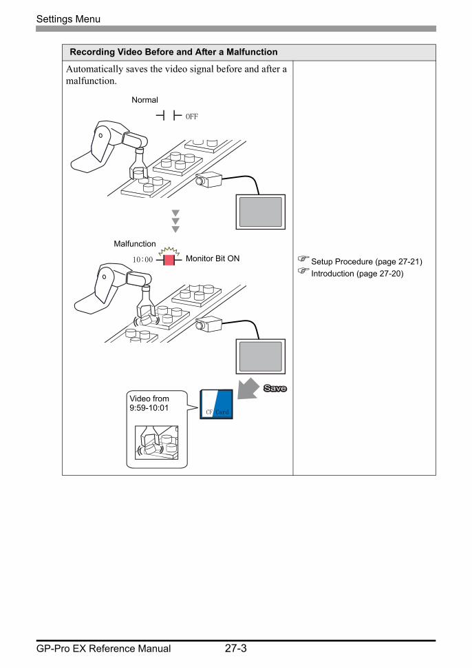
Recording Video Before and After a Malfunction
Automatically saves the video signal before and after a malfunction.
Setup Procedure (page 27-21)Introduction (page 27-20)
SaveSaveSave
Normal
Malfunction
Monitor Bit ON
CF Card
Video from 9:59-10:01
OFF
10:00

Settings Menu
GP-Pro EX Reference Manual 27-4
Playing Movies
Plays the movies in the specified order.
Setup Procedure (page 27-25)Introduction (page 27-24)DEF.SDX
XYZ.SDX
ABC.SDX
1.MC060527_152349.SDX 2.ABC.SDX 3.MC060527_152350.SDX
MC060527 1523.48.SDX
MC060527 152350.SDX
Play List
FTP server
CF Card
Movie File Movie File
Operating Procedure Play a movie file in the order of the Play List file
Beep

Settings Menu
GP-Pro EX Reference Manual 27-5
Plays the movie you want to see when you want to see it.
Setup Procedure (page 27-34)Introduction (page 27-24)
Playing Movies
MOVIE <DIR> step1.SDX step2.SDX step3.SDX
Date : 06/06/08 09:24 Size : 112 bytes
00:CF:/step2.SDX CF
FTP
PLAY
MOVIE <DIR> step1.SDX step2.SDX step3.SDX
Date : 06/06/08 09:24 Size : 112 bytes
00:CF:/step1.SDX 01:CF:/step2.SDX 02:CF:/step3.SDX
CF
FTP
PLAY
Touch the File Manager display
switch
File Manager
Plays the selected file
Beep
Settings Menu
GP-Pro EX Reference Manual 27-6
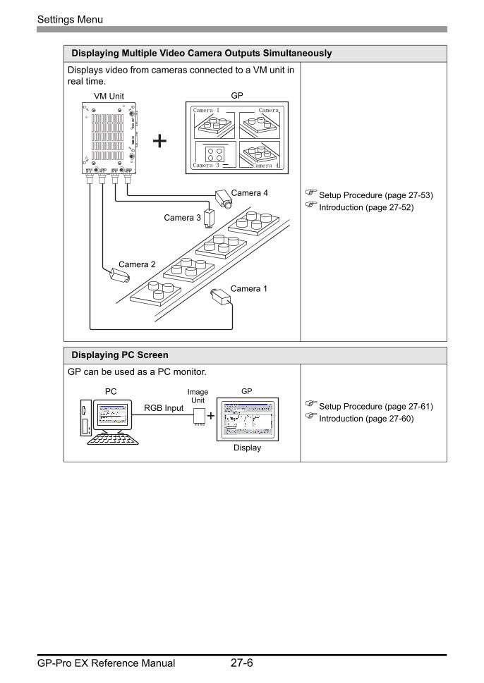
Displaying Multiple Video Camera Outputs Simultaneously
Displays video from cameras connected to a VM unit in real time.
Setup Procedure (page 27-53)Introduction (page 27-52)
Displaying PC Screen
GP can be used as a PC monitor.
Setup Procedure (page 27-61)Introduction (page 27-60)
VM Unit
Camera 2
Camera 1
Camera 3
Camera 4
Camera 1
Camera 3
Camera
Camera 4
GP
RGB Input
Image Unit
Display
PC GP
Settings Menu
GP-Pro EX Reference Manual 27-7
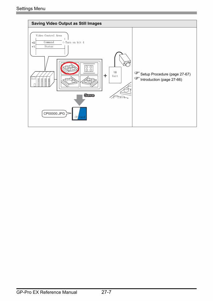
Saving Video Output as Still Images
Setup Procedure (page 27-67)Introduction (page 27-66)
+0+1
CP00000.JPG
SaveSaveSave
CF Card
Video Control Area
Command
Status
VM
Unit
<-Turn on bit 4
Displaying Video Camera Output
GP-Pro EX Reference Manual 27-8
27.2 Displaying Video Camera Output
27.2.1 Introduction
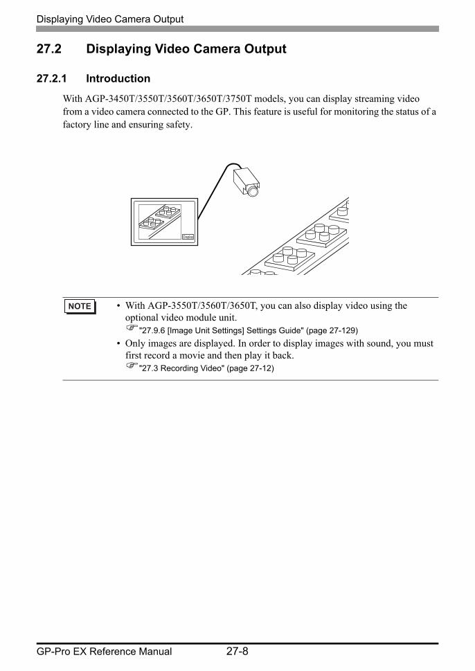
With AGP-3450T/3550T/3560T/3650T/3750T models, you can display streaming video from a video camera connected to the GP. This feature is useful for monitoring the status of a factory line and ensuring safety.
• With AGP-3550T/3560T/3650T, you can also display video using the optional video module unit.
"27.9.6 [Image Unit Settings] Settings Guide" (page 27-129)• Only images are displayed. In order to display images with sound, you must
first record a movie and then play it back."27.3 Recording Video" (page 27-12)
Display
Display
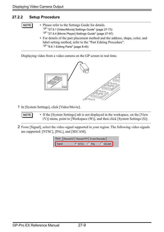
Displaying video from a video camera on the GP screen in real time.
Displaying Video Camera Output
GP-Pro EX Reference Manual 27-9
27.2.2 Setup Procedure
1 In [System Settings], click [Video/Movie].
2 From [Signal], select the video signal supported in your region. The following video signals are supported: [NTSC], [PAL], and [SECAM].
• Please refer to the Settings Guide for details."27.9.1 [Video/Movie] Settings Guide" (page 27-73)"27.9.4 [Movie Player] Settings Guide" (page 27-97)
• For details of the part placement method and the address, shape, color, and label setting method, refer to the "Part Editing Procedure".
"8.6.1 Editing Parts" (page 8-45)
• If the [System Settings] tab is not displayed in the workspace, on the [View (V)] menu, point to [Workspace (W)], and then click [System Settings (S)].
Displaying Video Camera Output
GP-Pro EX Reference Manual 27-10
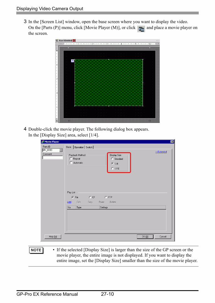
3 In the [Screen List] window, open the base screen where you want to display the video. On the [Parts (P)] menu, click [Movie Player (M)], or click and place a movie player on the screen.
4 Double-click the movie player. The following dialog box appears. In the [Display Size] area, select [1/4].
• If the selected [Display Size] is larger than the size of the GP screen or the movie player, the entire image is not displayed. If you want to display the entire image, set the [Display Size] smaller than the size of the movie player.
Displaying Video Camera Output
GP-Pro EX Reference Manual 27-11
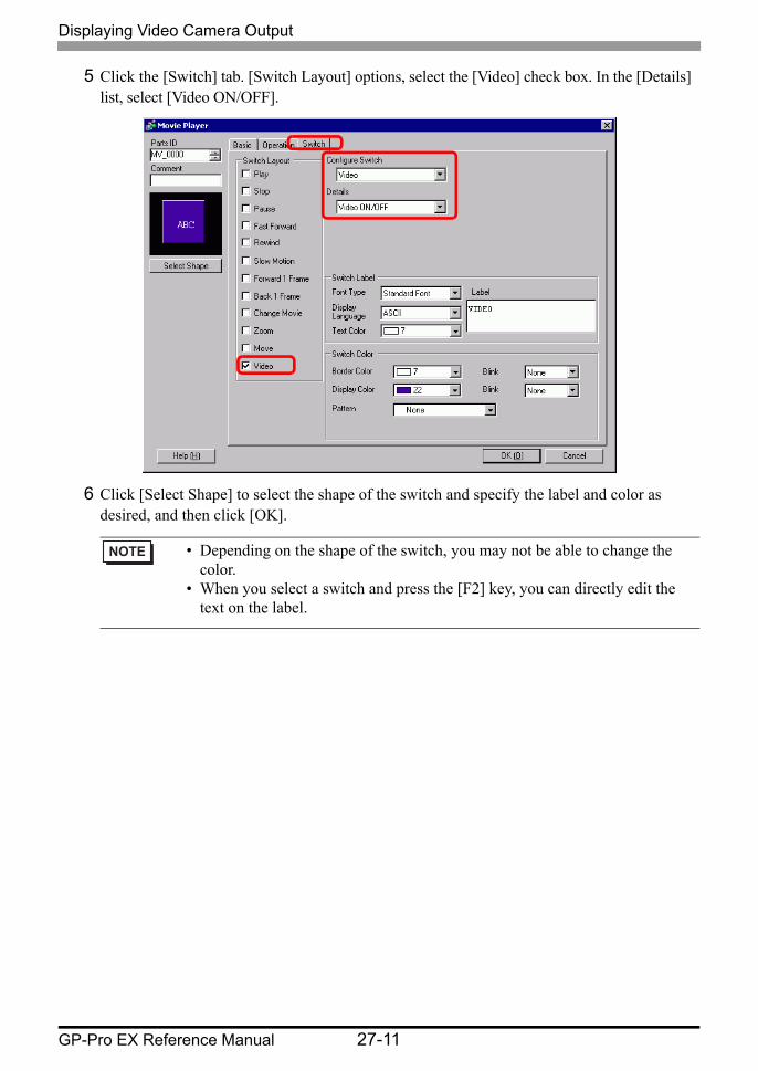
5 Click the [Switch] tab. [Switch Layout] options, select the [Video] check box. In the [Details] list, select [Video ON/OFF].
6 Click [Select Shape] to select the shape of the switch and specify the label and color as desired, and then click [OK].
• Depending on the shape of the switch, you may not be able to change the color.
• When you select a switch and press the [F2] key, you can directly edit the text on the label.
Recording Video
GP-Pro EX Reference Manual 27-12
27.3 Recording Video
27.3.1 Introduction
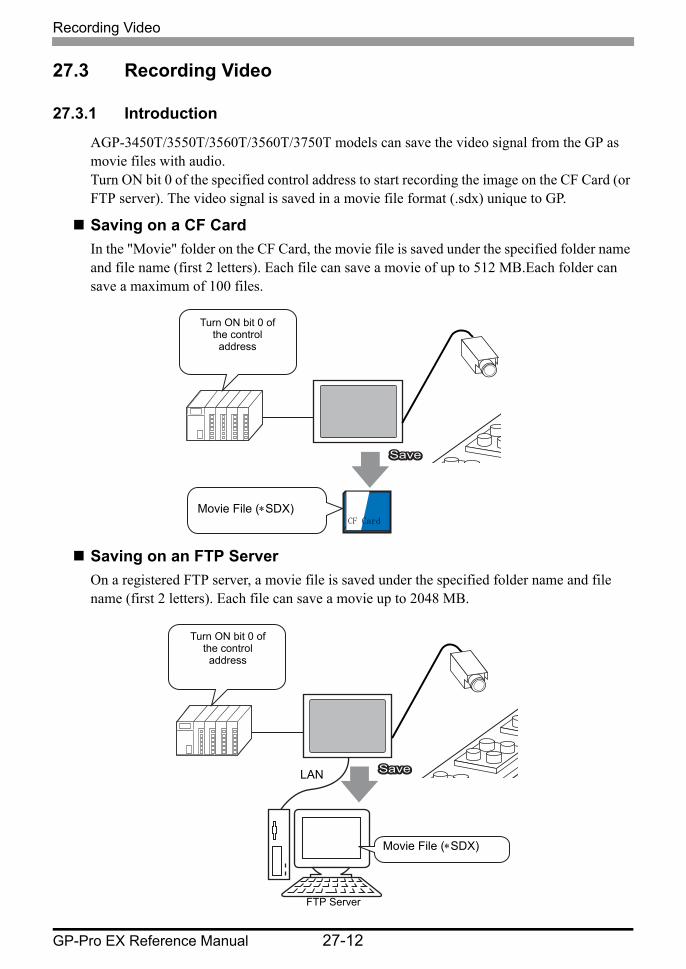
AGP-3450T/3550T/3560T/3560T/3750T models can save the video signal from the GP as movie files with audio.Turn ON bit 0 of the specified control address to start recording the image on the CF Card (or FTP server). The video signal is saved in a movie file format (.sdx) unique to GP.
Saving on a CF CardIn the "Movie" folder on the CF Card, the movie file is saved under the specified folder name and file name (first 2 letters). Each file can save a movie of up to 512 MB.Each folder can save a maximum of 100 files.
Saving on an FTP ServerOn a registered FTP server, a movie file is saved under the specified folder name and file name (first 2 letters). Each file can save a movie up to 2048 MB.
SaveSaveSave
Turn ON bit 0 of the control
address
Movie File (∗SDX)CF Card
Turn ON bit 0 of the control
address
Movie File (∗SDX)
LAN
FTP Server
SaveSaveSave
Recording Video
GP-Pro EX Reference Manual 27-13
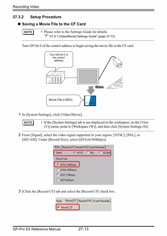
27.3.2 Setup Procedure
Saving a Movie File to the CF Card
Turn ON bit 0 of the control address to begin saving the movie file to the CF card.
1 In [System Settings], click [Video/Movie].
2 From [Signal], select the video signal supported in your region: [NTSC], [PAL], or [SECAM]. Under [Record Size], select [QVGA(384kbps)].
3 [Click the [Record CF] tab and select the [Record CF] check box.
• Please refer to the Settings Guide for details."27.9.1 [Video/Movie] Settings Guide" (page 27-73)
• If the [System Settings] tab is not displayed in the workspace, on the [View (V)] menu, point to [Workspace (W)], and then click [System Settings (S)].
SaveSaveSave
Turn ON bit 0 of the control
address
Movie File (∗SDX)CF Card
Recording Video
GP-Pro EX Reference Manual 27-14
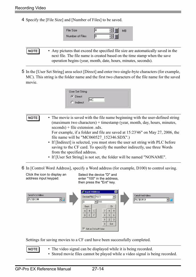
4 Specify the [File Size] and [Number of Files] to be saved.
5 In the [User Set String] area select [Direct] and enter two single-byte characters (for example, MC). This string is the folder name and the first two characters of the file name for the saved movie.
6 In [Control Word Address], specify a Word address (for example, D100) to control saving.
Settings for saving movies to a CF card have been successfully completed.
• Any pictures that exceed the specified file size are automatically saved in the next file. The file name is created based on the time stamp when the save operation begins (year, month, date, hours, minutes, seconds).
• The movie is saved with the file name beginning with the user-defined string (maximum two characters) + timestamp (year, month, day, hours, minutes, seconds) + file extension .sdx. For example, if a folder and file are saved at 15:23'46" on May 27, 2006, the file name will be "MC060527_152346.SDX".)
• If [Indirect] is selected, you must store the user set string with PLC before saving to the CF card. To specify the number indirectly, use three Words from the specified address.
• If [User Set String] is not set, the folder will be named "NONAME".
• The video signal can be displayed while it is being recorded.• Stored movie files cannot be played while a video signal is being recorded.
Click the icon to display an address input keypad.
Select the device "D" and enter "100" in the address, then press the "Ent" key.
Recording Video
GP-Pro EX Reference Manual 27-15
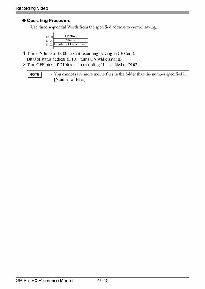
Operating ProcedureUse three sequential Words from the specified address to control saving.
1 Turn ON bit 0 of D100 to start recording (saving to CF Card). Bit 0 of status address (D101) turns ON while saving.
2 Turn OFF bit 0 of D100 to stop recording."1" is added to D102.
• You cannot save more movie files in the folder than the number specified in [Number of Files].
D100D101D102
ControlStatus
Number of Files Saved

Recording Video
GP-Pro EX Reference Manual 27-16
Saving a Movie File to the FTP Server
Turn ON bit 0 of the control address to start saving a movie file on the registered FTP server.
1 In the [System Settings], click [FTP Server].
• In order to save the files on an FTP server, you must have an FTP (File Transfer Protocol) server set up on the network in advance.
• Please refer to the Settings Guide for details."27.9.2 [FTP Server] Settings Guide" (page 27-93)"27.9.1 [Video/Movie] Settings Guide" (page 27-73)
• If the [System Settings] tab is not displayed in the workspace, on the [View (V)] menu, point to [Workspace (W)], and then click [System Settings (S)].
SaveSaveSave
Turn ON bit 0 of the control
address
Movie File (∗SDX)
LAN
FTP Server
Recording Video
GP-Pro EX Reference Manual 27-17
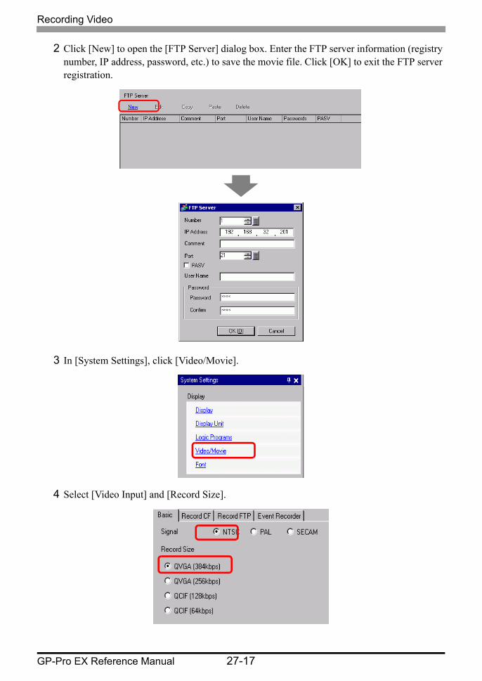
2 Click [New] to open the [FTP Server] dialog box. Enter the FTP server information (registry number, IP address, password, etc.) to save the movie file. Click [OK] to exit the FTP server registration.
3 In [System Settings], click [Video/Movie].
4 Select [Video Input] and [Record Size].

Recording Video
GP-Pro EX Reference Manual 27-18
5 [Click the [Record FTP] tab and select the [Record to FTP] check box.
6 In [FTP Server], select [Direct] then select the registration number of the FTP server registered in step 2.
7 In [File Size], set the maximum file size for the video.
8 In the [User Set String] area, select [Direct] and enter two single-byte characters (for example, MC). This string is the folder name and the first two characters of the file name under which the movie is saved.
9 [Timeout] field, enter how much time is spent trying to connect to the FTP server (for example, 60 seconds).
• Any pictures that exceed the specified file size are automatically saved in the next file.The file name is created based on the time stamp when the save operation begins (year, month, date, hours, minutes, seconds).
• The movie is saved with the file name beginning with the user-defined string (maximum two characters) + time stamp + file extension .sdx. For example, if a folder and file are saved at 15:23'26" on May 27, 2006, the file name will be "MC060527_152346.SDX".)
• If [Indirect] is selected, you must specify the server registry number with PLC before saving on the FTP server.To specify the number indirectly, use three Words from the specified address.
• If you do not specify a string in the [User Specified String] field, the folder is named "NONAME."

Recording Video
GP-Pro EX Reference Manual 27-19
10 In [Control Word Address], specify a Word address (for example, D100) to control saving.
Movie save setting on the FTP server has been successfully completed
Operating ProcedureUse two sequential Words from the specified address to control saving.
1 Turn ON bit 0 of D100 to start recording (saving on the FTP server). Bit 0 of status address (D101) turns ON while saving.
2 Turn OFF bit 0 of D100 to stop recording.
• The video signal can be displayed while it is being recorded.• Stored movie files cannot be played while a video signal is being recorded.
Click the icon to display an address input keypad.
Select the device "D" and enter "100" in the address, then press the "Ent" key.
D100 D101
ControlStatus
Recording Video Before and After a Malfunction
GP-Pro EX Reference Manual 27-20
27.4 Recording Video Before and After a Malfunction
27.4.1 Introduction
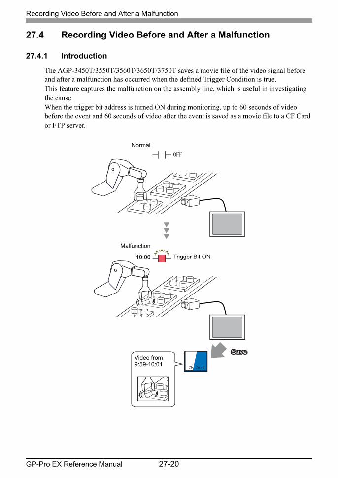
The AGP-3450T/3550T/3560T/3650T/3750T saves a movie file of the video signal before and after a malfunction has occurred when the defined Trigger Condition is true. This feature captures the malfunction on the assembly line, which is useful in investigating the cause.When the trigger bit address is turned ON during monitoring, up to 60 seconds of video before the event and 60 seconds of video after the event is saved as a movie file to a CF Card or FTP server.
SaveSaveSave
Normal
Malfunction
Trigger Bit ON
CF Card
Video from 9:59-10:01
OFF
10:00
Recording Video Before and After a Malfunction
GP-Pro EX Reference Manual 27-21
27.4.2 Setup Procedure
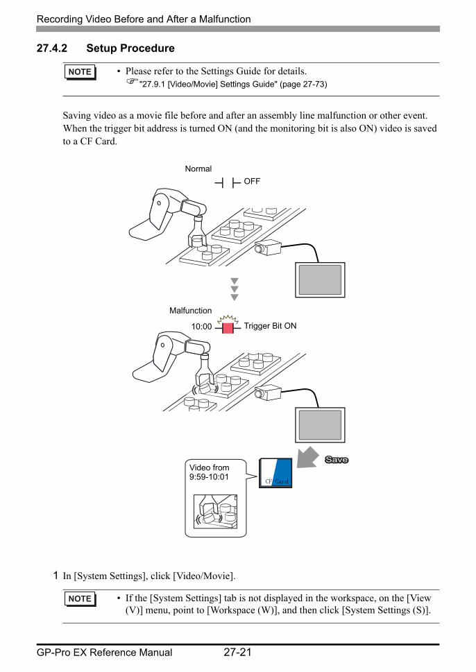
Saving video as a movie file before and after an assembly line malfunction or other event. When the trigger bit address is turned ON (and the monitoring bit is also ON) video is saved to a CF Card.
1 In [System Settings], click [Video/Movie].
• Please refer to the Settings Guide for details."27.9.1 [Video/Movie] Settings Guide" (page 27-73)
• If the [System Settings] tab is not displayed in the workspace, on the [View (V)] menu, point to [Workspace (W)], and then click [System Settings (S)].
SaveSaveSave
Normal
Malfunction
Trigger Bit ON
CF Card
Video from 9:59-10:01
OFF
10:00
Recording Video Before and After a Malfunction
GP-Pro EX Reference Manual 27-22
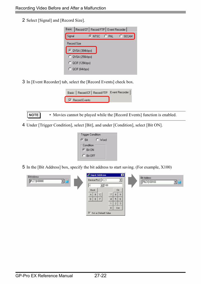
2 Select [Signal] and [Record Size].
3 In [Event Recorder] tab, select the [Record Events] check box.
4 Under [Trigger Condition], select [Bit], and under [Condition], select [Bit ON].
5 In the [Bit Address] box, specify the bit address to start saving. (For example, X100)
• Movies cannot be played while the [Record Events] function is enabled.
Recording Video Before and After a Malfunction
GP-Pro EX Reference Manual 27-23
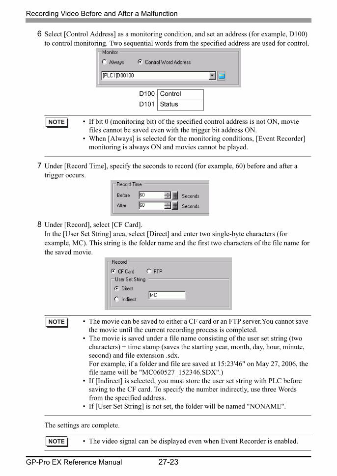
6 Select [Control Address] as a monitoring condition, and set an address (for example, D100) to control monitoring. Two sequential words from the specified address are used for control.
7 Under [Record Time], specify the seconds to record (for example, 60) before and after a trigger occurs.
8 Under [Record], select [CF Card]. In the [User Set String] area, select [Direct] and enter two single-byte characters (for example, MC). This string is the folder name and the first two characters of the file name for the saved movie.
The settings are complete.
D100 ControlD101 Status
• If bit 0 (monitoring bit) of the specified control address is not ON, movie files cannot be saved even with the trigger bit address ON.
• When [Always] is selected for the monitoring conditions, [Event Recorder] monitoring is always ON and movies cannot be played.
• The movie can be saved to either a CF card or an FTP server.You cannot save the movie until the current recording process is completed.
• The movie is saved under a file name consisting of the user set string (two characters) + time stamp (saves the starting year, month, day, hour, minute, second) and file extension .sdx. For example, if a folder and file are saved at 15:23'46" on May 27, 2006, the file name will be "MC060527_152346.SDX".)
• If [Indirect] is selected, you must store the user set string with PLC before saving to the CF card. To specify the number indirectly, use three Words from the specified address.
• If [User Set String] is not set, the folder will be named "NONAME".
• The video signal can be displayed even when Event Recorder is enabled.
Playing Movies
GP-Pro EX Reference Manual 27-24
27.5 Playing Movies
27.5.1 Introduction
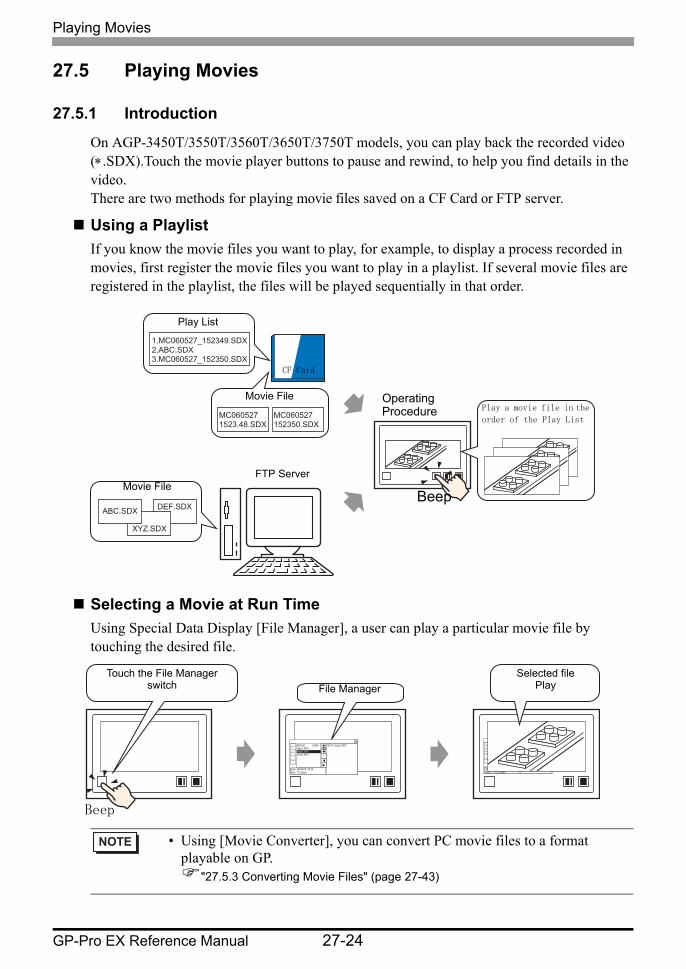
On AGP-3450T/3550T/3560T/3650T/3750T models, you can play back the recorded video (∗.SDX).Touch the movie player buttons to pause and rewind, to help you find details in the video.There are two methods for playing movie files saved on a CF Card or FTP server.
Using a PlaylistIf you know the movie files you want to play, for example, to display a process recorded in movies, first register the movie files you want to play in a playlist. If several movie files are registered in the playlist, the files will be played sequentially in that order.
Selecting a Movie at Run TimeUsing Special Data Display [File Manager], a user can play a particular movie file by touching the desired file.
• Using [Movie Converter], you can convert PC movie files to a format playable on GP.
"27.5.3 Converting Movie Files" (page 27-43)
DEF.SDX
XYZ.SDX
ABC.SDX
1.MC060527_152349.SDX 2.ABC.SDX 3.MC060527_152350.SDX
MC060527 1523.48.SDX
MC060527 152350.SDX
Play List
Movie File
Movie FileFTP Server
CF Card
Operating Procedure Play a movie file in the
order of the Play List
Beep
MOVIE <DIR> step1.SDX step2.SDX step3.SDX
Date: 06/06/08 09:24 Size: 112 bytes
00:CF:/step2.SDX CF
FTP
PLAY
MOVIE <DIR> step1.SDX step2.SDX step3.SDX
Date : 06/06/08 09:24 Size : 112 bytes
00:CF:/step1.SDX 01:CF:/step2.SDX 02:CF:/step3.SDX
CF
FTP
PLAY
Touch the File Managerswitch File Manager
Selected file Play
Beep
Playing Movies
GP-Pro EX Reference Manual 27-25
27.5.2 Setup Procedure
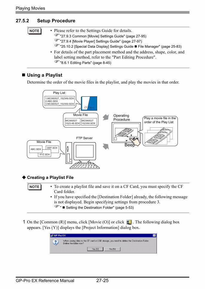
Using a PlaylistDetermine the order of the movie files in the playlist, and play the movies in that order.
Creating a Playlist File
1 On the [Common (R)] menu, click [Movie (O)] or click . The following dialog box appears. [Yes (Y)] displays the [Project Information] dialog box.
• Please refer to the Settings Guide for details."27.9.3 Common [Movie] Settings Guide" (page 27-95)"27.9.4 [Movie Player] Settings Guide" (page 27-97)"25.10.2 [Special Data Display] Settings Guide File Manager" (page 25-83)
• For details of the part placement method and the address, shape, color, and label setting method, refer to the "Part Editing Procedure".
"8.6.1 Editing Parts" (page 8-45)
• To create a playlist file and save it on a CF Card, you must specify the CF Card folder.
• If you have specified the [Destination Folder] already, the following message is not displayed. Begin specifying settings from procedure 3.
" Setting the Destination Folder" (page 5-53)
DEF.SDX
XYZ.SDX
ABC.SDX
1.MC060527_152349.SDX 2.ABC.SDX 3.MC060527_152350.SDX
MC060527 1523.48.SDX
MC060527 152350.SDX
Play List
Movie File
Movie FileFTP Server
CF Card
Operating Procedure Play a movie file in the
order of the Play List
Beep
Playing Movies
GP-Pro EX Reference Manual 27-26
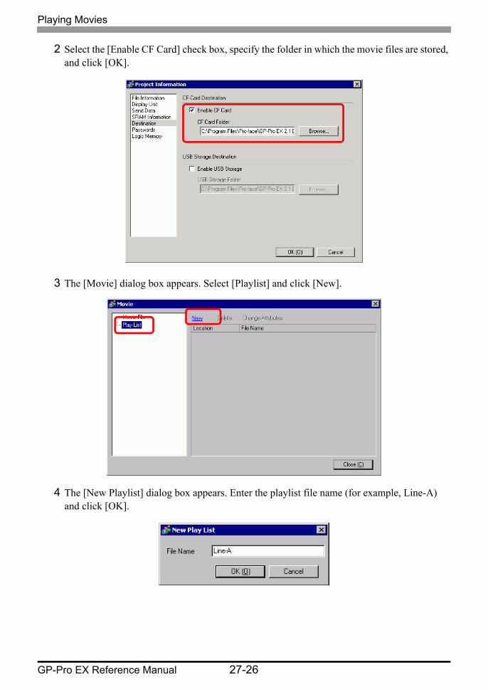
2 Select the [Enable CF Card] check box, specify the folder in which the movie files are stored, and click [OK].
3 The [Movie] dialog box appears. Select [Playlist] and click [New].
4 The [New Playlist] dialog box appears. Enter the playlist file name (for example, Line-A) and click [OK].
Playing Movies
GP-Pro EX Reference Manual 27-27
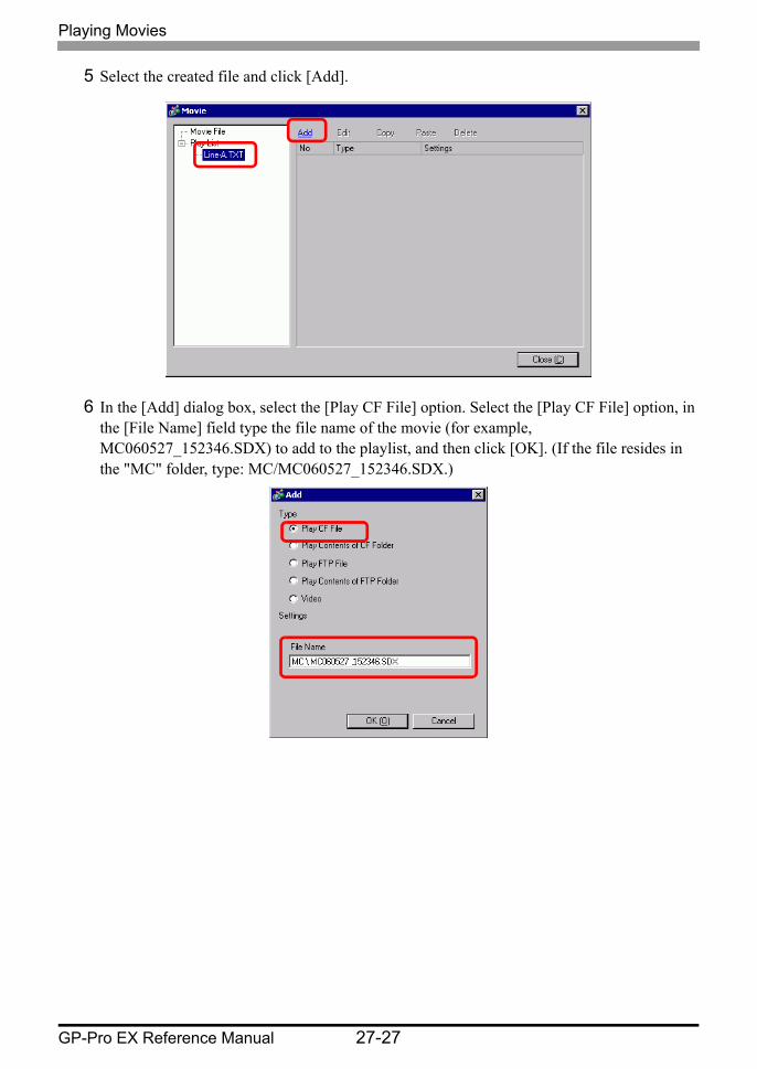
5 Select the created file and click [Add].
6 In the [Add] dialog box, select the [Play CF File] option. Select the [Play CF File] option, in the [File Name] field type the file name of the movie (for example, MC060527_152346.SDX) to add to the playlist, and then click [OK]. (If the file resides in the "MC" folder, type: MC/MC060527_152346.SDX.)
Playing Movies
GP-Pro EX Reference Manual 27-28
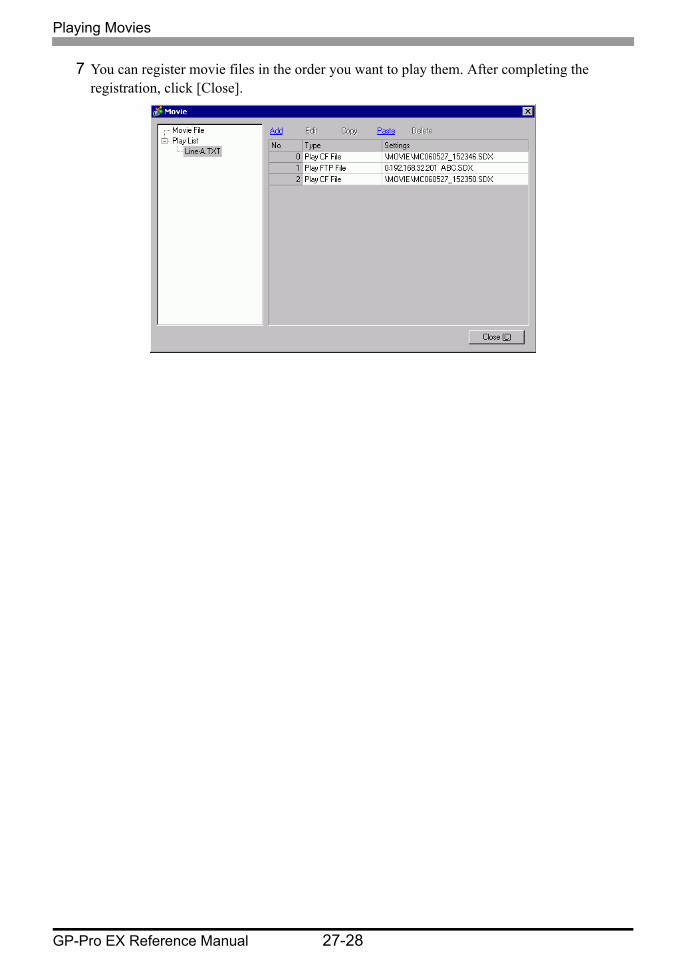
7 You can register movie files in the order you want to play them. After completing the registration, click [Close].
Playing Movies
GP-Pro EX Reference Manual 27-29
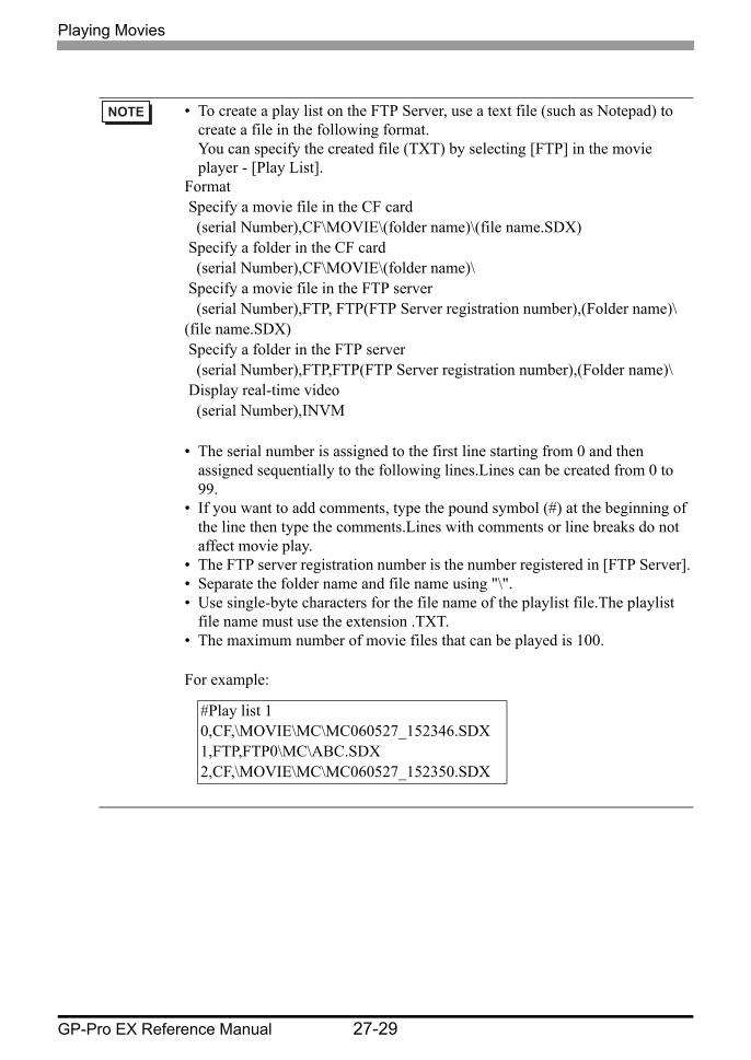
• To create a play list on the FTP Server, use a text file (such as Notepad) to create a file in the following format. You can specify the created file (TXT) by selecting [FTP] in the movie player - [Play List].
Format Specify a movie file in the CF card (serial Number),CF\MOVIE\(folder name)\(file name.SDX) Specify a folder in the CF card (serial Number),CF\MOVIE\(folder name)\ Specify a movie file in the FTP server (serial Number),FTP, FTP(FTP Server registration number),(Folder name)\ (file name.SDX) Specify a folder in the FTP server (serial Number),FTP,FTP(FTP Server registration number),(Folder name)\ Display real-time video (serial Number),INVM
• The serial number is assigned to the first line starting from 0 and then assigned sequentially to the following lines.Lines can be created from 0 to 99.
• If you want to add comments, type the pound symbol (#) at the beginning of the line then type the comments.Lines with comments or line breaks do not affect movie play.
• The FTP server registration number is the number registered in [FTP Server].• Separate the folder name and file name using "\".• Use single-byte characters for the file name of the playlist file.The playlist
file name must use the extension .TXT.• The maximum number of movie files that can be played is 100.
For example:
#Play list 10,CF,\MOVIE\MC\MC060527_152346.SDX1,FTP,FTP0\MC\ABC.SDX2,CF,\MOVIE\MC\MC060527_152350.SDX
Playing Movies
GP-Pro EX Reference Manual 27-30
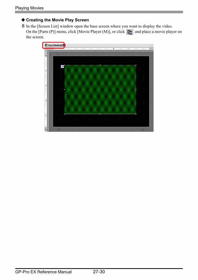
Creating the Movie Play Screen8 In the [Screen List] window open the base screen where you want to display the video.
On the [Parts (P)] menu, click [Movie Player (M)], or click and place a movie player on the screen.

Playing Movies
GP-Pro EX Reference Manual 27-31
9 Double-click the movie player. The following dialog box appears. In the [Display Size] area select [1/4].
10 In [Playlist], select [CF] and select the check box next to the file created in step 7. (For example, Line-A.TXT)
• If the selected [Display Size] is larger than the size of the GP screen or the movie player, the entire image is not displayed. If you want to display the entire image, set the [Display Size] smaller than the size of the movie player.
• If you select [File], the playlist can be specified in the Movie Player. In this case, the playlist file is not required.
Playing Movies
GP-Pro EX Reference Manual 27-32
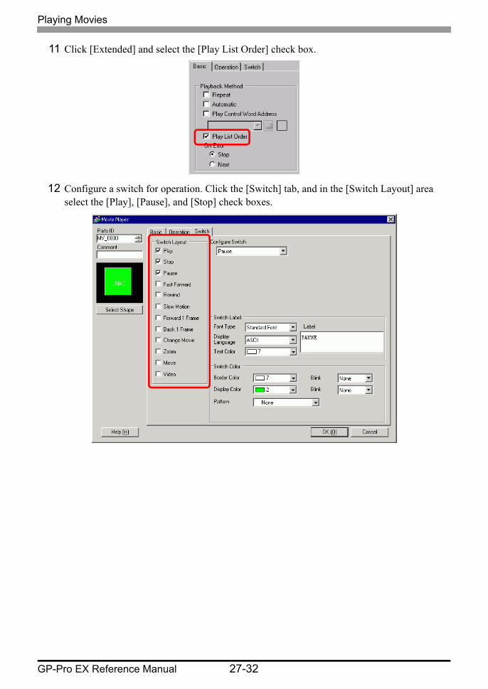
11 Click [Extended] and select the [Play List Order] check box.
12 Configure a switch for operation. Click the [Switch] tab, and in the [Switch Layout] area select the [Play], [Pause], and [Stop] check boxes.

Playing Movies
GP-Pro EX Reference Manual 27-33
13 In [Select Shape], select the shape of the switch, and specify the label and color as necessary.Click [OK] to complete the settings.
The switches can be individually selected and moved to a desired location.
• You cannot specify individual shapes and colors for switches drawn using the [Switch] tab on the [Movie Player] part. You can only specify individual labels. If you want to define specific shapes and colors for each switch, do not use the [Switch] tab. Instead, use the Switch/Lamp part to create a [Movie Player Switch] from the [Special Switch] settings.
"10.15.2 Word Switch" (page 10-65)• Depending on the shape of the switch, you may not be able to change the
color.• When you select a switch and press the [F2] key, you can directly edit the
text on the label.
Playing Movies
GP-Pro EX Reference Manual 27-34
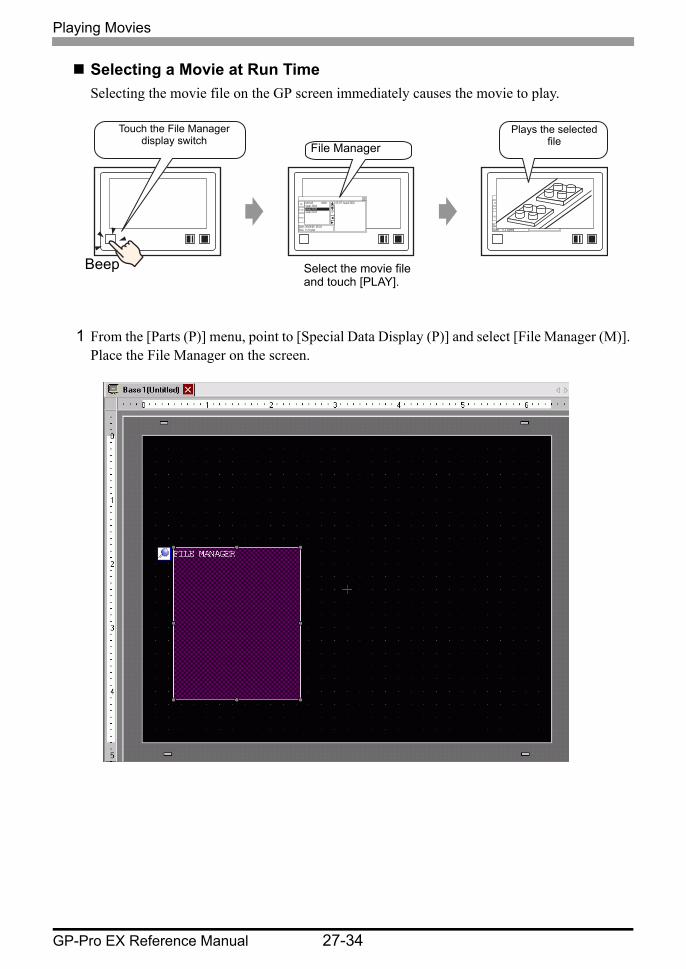
Selecting a Movie at Run TimeSelecting the movie file on the GP screen immediately causes the movie to play.
1 From the [Parts (P)] menu, point to [Special Data Display (P)] and select [File Manager (M)]. Place the File Manager on the screen.
MOVIE <DIR> step1.SDX step2.SDX step3.SDX
Date: 06/06/08 09:24 Size: 112 bytes
00:CF:/step2.SDX CF
FTP
PLAY
MOVIE <DIR> step1.SDX step2.SDX step3.SDX
Date : 06/06/08 09:24 Size : 112 bytes
00:CF:/step1.SDX 01:CF:/step2.SDX 02:CF:/step3.SDX
CF
FTP
PLAY
Select the movie file and touch [PLAY].
Touch the File Manager display switch File Manager
Plays the selected file
Beep

Playing Movies
GP-Pro EX Reference Manual 27-35
2 Double-click the Special Data Display [File Manager]. The following dialog box appears.
3 In [Action Mode], select [Select Movie]. [Selection Mode], select [Multiple]. [Target Data], select [CF/FTP].
Playing Movies
GP-Pro EX Reference Manual 27-36
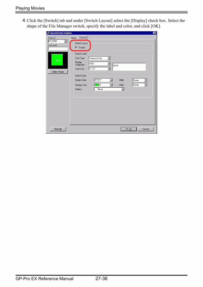
4 Click the [Switch] tab and under [Switch Layout] select the [Display] check box. Select the shape of the File Manager switch, specify the label and color, and click [OK].

Playing Movies
GP-Pro EX Reference Manual 27-37
The Special Data Display [File Manager] has been specified. The switches placed with the [Switch] tab under [File Manager] can be individually selected and moved to a desired location.
5 On the [Parts (P)] menu, click [Movie Display] and place it in the same Base screen as [File Manager].
• Only one Special Data Display [File Manager] can be placed on one screen.
Playing Movies
GP-Pro EX Reference Manual 27-38
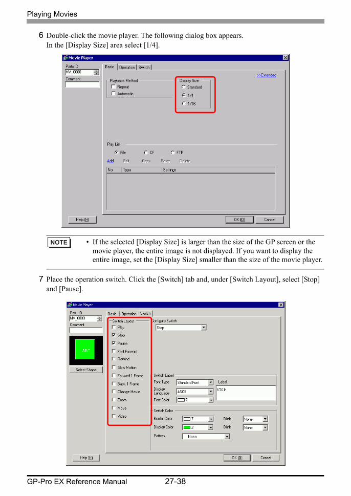
6 Double-click the movie player. The following dialog box appears. In the [Display Size] area select [1/4].
7 Place the operation switch. Click the [Switch] tab and, under [Switch Layout], select [Stop] and [Pause].
• If the selected [Display Size] is larger than the size of the GP screen or the movie player, the entire image is not displayed. If you want to display the entire image, set the [Display Size] smaller than the size of the movie player.
Playing Movies
GP-Pro EX Reference Manual 27-39
8 In [Select Shape], select the shape of the switch, specify the label and color, and click [OK].
The switches placed with the [Switch] tab in [Movie Player] can be individually selected and moved to a desired location.
• You cannot specify individual shapes and colors for switches drawn using the [Switch] tab on the [Movie Player] part. You can only specify individual labels. If you want to define specific shapes and colors for each switch, do not use the [Switch] tab. Instead, use the Switch/Lamp part to create a [Movie Player Switch] from the [Special Switch] settings.
"10.15.4 Special Switch" (page 10-70)• Depending on the shape of the switch, you may not be able to change the
color.• When you select a switch and press the [F2] key, you can directly edit the
text on the label.
Playing Movies
GP-Pro EX Reference Manual 27-40
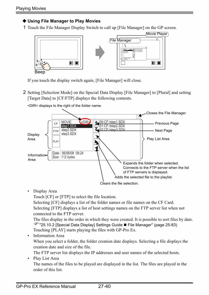
Using File Manager to Play Movies1 Touch the File Manager Display Switch to call up [File Manager] on the GP screen.
If you touch the display switch again, [File Manager] will close.
2 Setting [Selection Mode] on the Special Data Display [File Manager] to [Plural] and setting [Target Data] to [CF/FTP] displays the following contents.
• Display AreaTouch [CF] or [FTP] to select the file location.Selecting [CF] displays a list of the folder names or file names on the CF Card.Selecting [FTP] displays a list of host settings names on the FTP server list when not connected to the FTP server.The files display in the order in which they were created. It is possible to sort files by date.
"25.10.2 [Special Data Display] Settings Guide File Manager" (page 25-83)Touching [PLAY] starts playing the files with GP-Pro Ex.
• Information AreaWhen you select a folder, the folder creation date displays. Selecting a file displays the creation date and size of the file.The FTP server list displays the IP addresses and user names of the selected hosts.
• Play List AreaThe names of the files to be played are displayed in the list. The files are played in the order of this list.
MOVIE <DIR> step1.SDX step2.SDX step3.SDX
Date : 06/06/08 09:24 Size : 112 bytes
00:CF:/step1.SDX 01:CF:/step2.SDX 02:CF:/step3.SDX
CF
FTP
PLAY
File Manager
Movie Player
Beep
MOVIE <DIR> step1.SDX step2.SDX step3.SDX
Date : 06/06/08 09:24 Size : 112 bytes
00:CF:/step1.SDX 01:CF:/step2.SDX 02:CF:/step3.SDX
CF
FTP
PLAY
Closes the File Manager.
Previous Page
Next Page
Adds the selected file to the playlist.
Clears the file selection.
Display Area
Information Area
<DIR> displays to the right of the folder name.
Expands the folder when selected.Connects to the FTP server when the list of FTP servers is displayed.
Play List Area

Playing Movies
GP-Pro EX Reference Manual 27-41
3 Selecting the folder and touching the key displays a list of all the files in the folder.
4 On the GP, select the movie file you want to play and touch the key to add the file to the playlist. Touching [PLAY] starts playing the files in the order registered in the playlist.
• To return to the above tree (the list of folders) from the file list page, select ".. <DIR> " in the first line and touch the key.
• After connecting to the FTP server selected with key, selecting [FTP] displays the file list.
MOVIE <DIR> step1.SDX step2.SDX step3.SDX
Date : 06/06/08 09:24 Size : 112 bytes
CF
FTP
PLAY
CF Card FTP Server
FTP1 FTP0
ftp : //192.168.32.201 USER : factory1
CF
FTP
PLAY
MOVIE <DIR> step1.SDX step2.SDX step3.SDX
Date : 06/06/08 09:24 Size : 112 bytes
00:CF:/step1.SDX 01:CF:/step2.SDX 02:CF:/step3.SDX
CF
FTP
PLAY
Playing Movies
GP-Pro EX Reference Manual 27-42
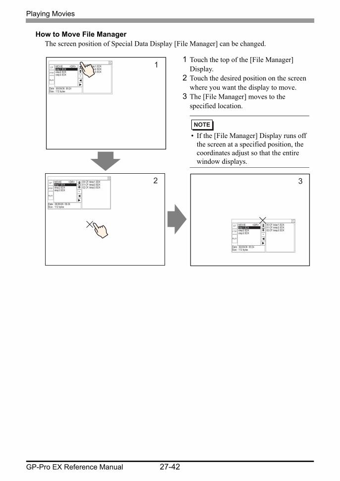
How to Move File ManagerThe screen position of Special Data Display [File Manager] can be changed.
MOVIE <DIR>step1.SDXstep2.SDXstep3.SDX
Date : 06/06/08 09:24Size : 112 bytes
00:CF:/step1.SDX 01:CF:/step2.SDX 02:CF:/step3.SDX
CF
FTP
PLAY
1
MOVIE <DIR>step1.SDXstep2.SDXstep3.SDX
Date : 06/06/08 09:24Size : 112 bytes
00:CF:/step1.SDX 01:CF:/step2.SDX 02:CF:/step3.SDX
CF
FTP
PLAY
2
MOVIE <DIR>step1.SDXstep2.SDXstep3.SDX
Date : 06/06/08 09:24Size : 112 bytes
00:CF:/step1.SDX 01:CF:/step2.SDX 02:CF:/step3.SDX
CF
FTP
PLAY
3
1 Touch the top of the [File Manager] Display.
2 Touch the desired position on the screen where you want the display to move.
3 The [File Manager] moves to the specified location.
• If the [File Manager] Display runs off the screen at a specified position, the coordinates adjust so that the entire window displays.
Playing Movies
GP-Pro EX Reference Manual 27-43
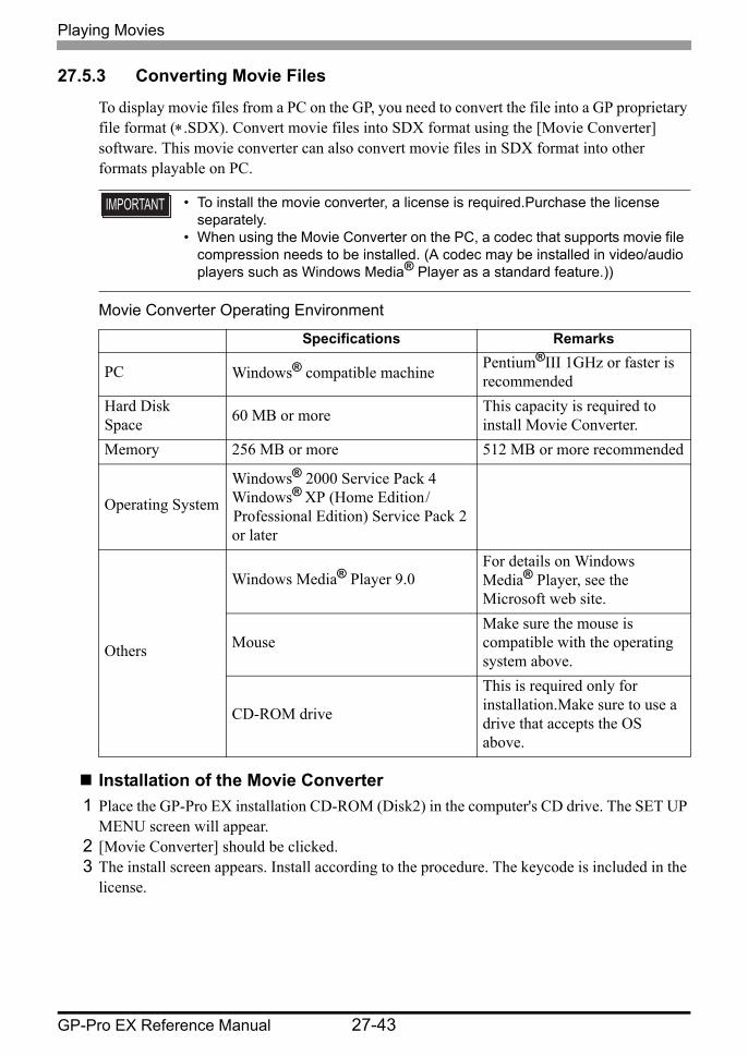
27.5.3 Converting Movie Files
To display movie files from a PC on the GP, you need to convert the file into a GP proprietary file format (∗.SDX). Convert movie files into SDX format using the [Movie Converter] software. This movie converter can also convert movie files in SDX format into other formats playable on PC.
Movie Converter Operating Environment
Installation of the Movie Converter1 Place the GP-Pro EX installation CD-ROM (Disk2) in the computer's CD drive. The SET UP
MENU screen will appear.2 [Movie Converter] should be clicked.3 The install screen appears. Install according to the procedure. The keycode is included in the
license.
• To install the movie converter, a license is required.Purchase the license separately.
• When using the Movie Converter on the PC, a codec that supports movie file compression needs to be installed. (A codec may be installed in video/audio players such as Windows Media® Player as a standard feature.))
Specifications Remarks
PC Windows® compatible machine Pentium®III 1GHz or faster is recommended
Hard Disk Space 60 MB or more This capacity is required to
install Movie Converter.Memory 256 MB or more 512 MB or more recommended
Operating SystemWindows® 2000 Service Pack 4 Windows® XP (Home Edition / Professional Edition) Service Pack 2 or later
Others
Windows Media® Player 9.0For details on Windows Media® Player, see the Microsoft web site.
MouseMake sure the mouse is compatible with the operating system above.
CD-ROM drive
This is required only for installation.Make sure to use a drive that accepts the OS above.
Playing Movies
GP-Pro EX Reference Manual 27-44
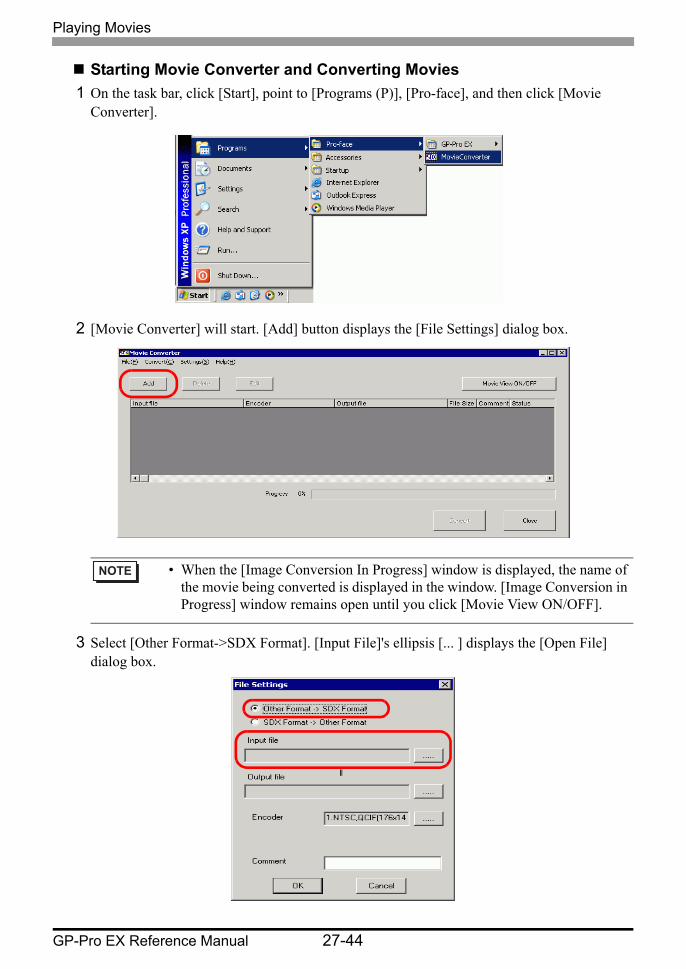
Starting Movie Converter and Converting Movies1 On the task bar, click [Start], point to [Programs (P)], [Pro-face], and then click [Movie
Converter].
2 [Movie Converter] will start. [Add] button displays the [File Settings] dialog box.
3 Select [Other Format->SDX Format]. [Input File]'s ellipsis [... ] displays the [Open File] dialog box.
• When the [Image Conversion In Progress] window is displayed, the name of the movie being converted is displayed in the window. [Image Conversion in Progress] window remains open until you click [Movie View ON/OFF].
Playing Movies
GP-Pro EX Reference Manual 27-45
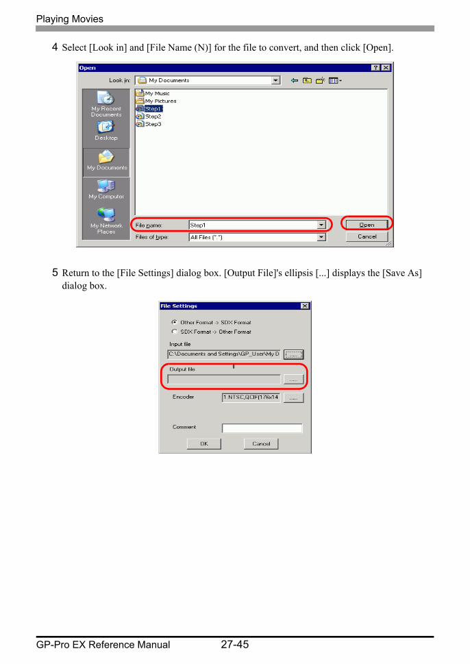
4 Select [Look in] and [File Name (N)] for the file to convert, and then click [Open].
5 Return to the [File Settings] dialog box. [Output File]'s ellipsis [...] displays the [Save As] dialog box.
Playing Movies
GP-Pro EX Reference Manual 27-46
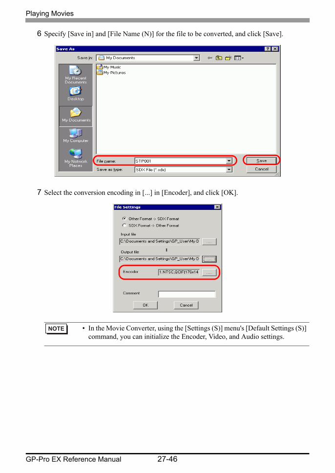
6 Specify [Save in] and [File Name (N)] for the file to be converted, and click [Save].
7 Select the conversion encoding in [...] in [Encoder], and click [OK].
• In the Movie Converter, using the [Settings (S)] menu's [Default Settings (S)] command, you can initialize the Encoder, Video, and Audio settings.
Playing Movies
GP-Pro EX Reference Manual 27-47
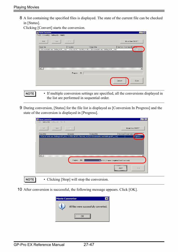
8 A list containing the specified files is displayed. The state of the current file can be checked in [Status]. Clicking [Convert] starts the conversion.
9 During conversion, [Status] for the file list is displayed as [Conversion In Progress] and the state of the conversion is displayed in [Progress].
10 After conversion is successful, the following message appears. Click [OK].
• If multiple conversion settings are specified, all the conversions displayed in the list are performed in sequential order.
• Clicking [Stop] will stop the conversion.
Playing Movies
GP-Pro EX Reference Manual 27-48
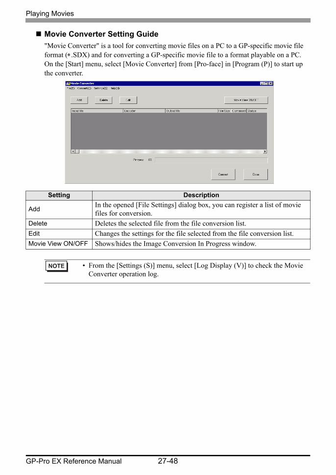
Movie Converter Setting Guide"Movie Converter" is a tool for converting movie files on a PC to a GP-specific movie file format (∗.SDX) and for converting a GP-specific movie file to a format playable on a PC.On the [Start] menu, select [Movie Converter] from [Pro-face] in [Program (P)] to start up the converter.
Setting Description
Add In the opened [File Settings] dialog box, you can register a list of movie files for conversion.
Delete Deletes the selected file from the file conversion list.Edit Changes the settings for the file selected from the file conversion list.Movie View ON/OFF Shows/hides the Image Conversion In Progress window.
• From the [Settings (S)] menu, select [Log Display (V)] to check the Movie Converter operation log.
Playing Movies
GP-Pro EX Reference Manual 27-49
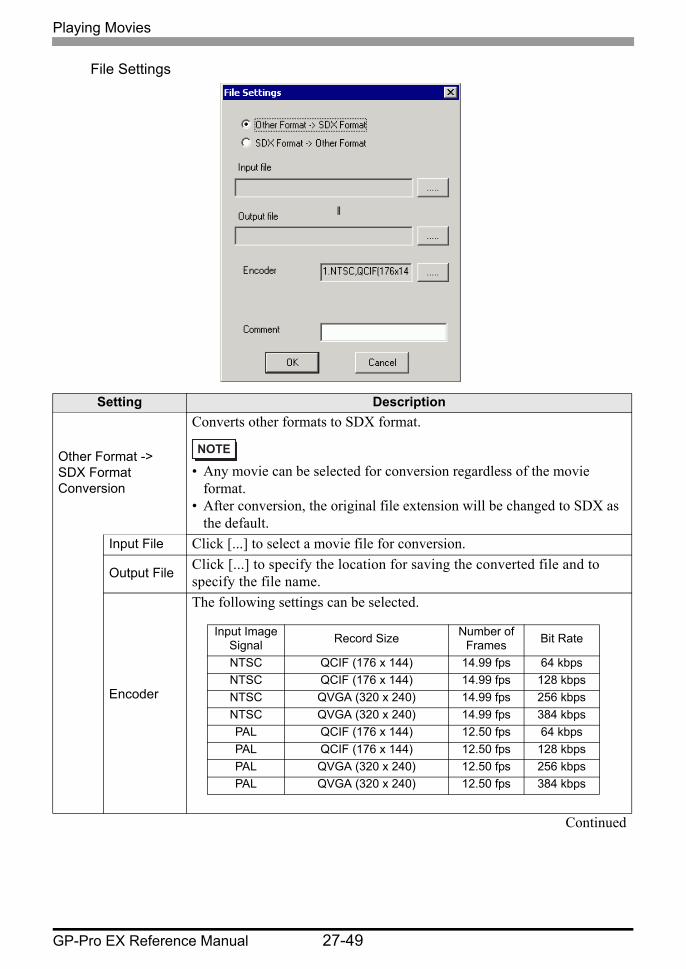
File Settings
Setting Description
Other Format -> SDX Format Conversion
Converts other formats to SDX format.
• Any movie can be selected for conversion regardless of the movie format.
• After conversion, the original file extension will be changed to SDX as the default.
Input File Click [...] to select a movie file for conversion.
Output File Click [...] to specify the location for saving the converted file and to specify the file name.
Encoder
The following settings can be selected.
Continued
Input Image Signal Record Size Number of
Frames Bit Rate
NTSC QCIF (176 x 144) 14.99 fps 64 kbpsNTSC QCIF (176 x 144) 14.99 fps 128 kbpsNTSC QVGA (320 x 240) 14.99 fps 256 kbpsNTSC QVGA (320 x 240) 14.99 fps 384 kbpsPAL QCIF (176 x 144) 12.50 fps 64 kbpsPAL QCIF (176 x 144) 12.50 fps 128 kbpsPAL QVGA (320 x 240) 12.50 fps 256 kbpsPAL QVGA (320 x 240) 12.50 fps 384 kbps
Playing Movies
GP-Pro EX Reference Manual 27-50
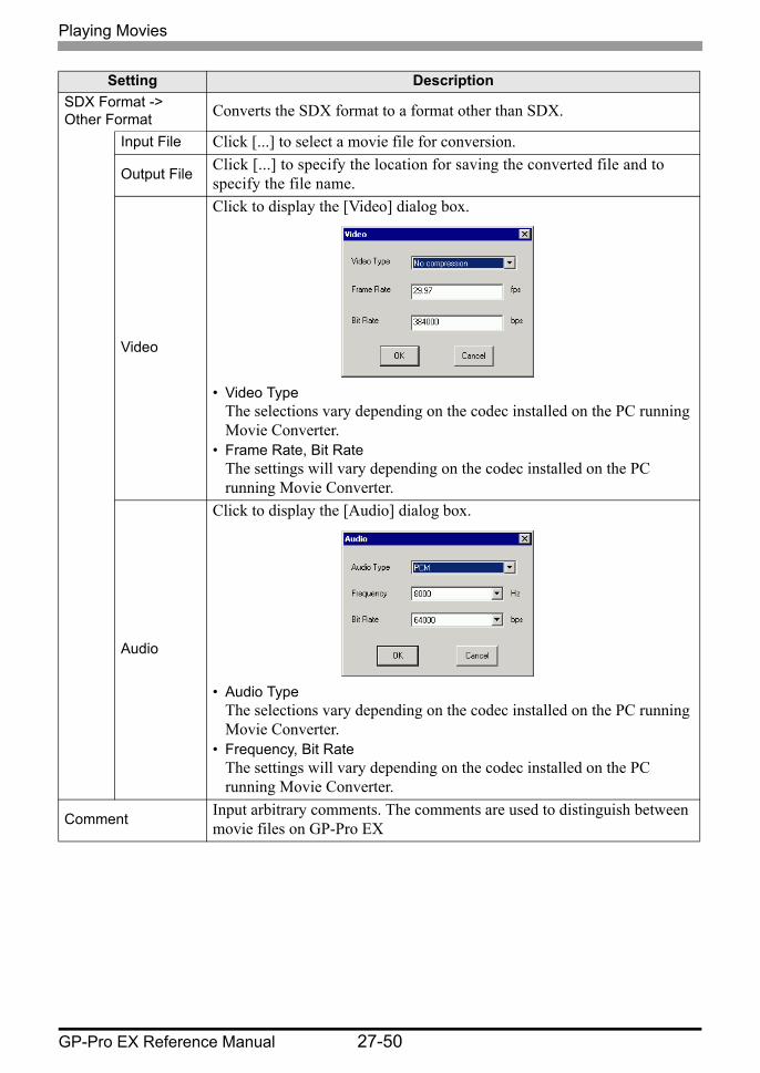
SDX Format -> Other Format Converts the SDX format to a format other than SDX.
Input File Click [...] to select a movie file for conversion.
Output File Click [...] to specify the location for saving the converted file and to specify the file name.
Video
Click to display the [Video] dialog box.
• Video TypeThe selections vary depending on the codec installed on the PC running Movie Converter.
• Frame Rate, Bit RateThe settings will vary depending on the codec installed on the PC running Movie Converter.
Audio
Click to display the [Audio] dialog box.
• Audio TypeThe selections vary depending on the codec installed on the PC running Movie Converter.
• Frequency, Bit RateThe settings will vary depending on the codec installed on the PC running Movie Converter.
Comment Input arbitrary comments. The comments are used to distinguish between movie files on GP-Pro EX
Setting Description
Playing Movies
GP-Pro EX Reference Manual 27-51
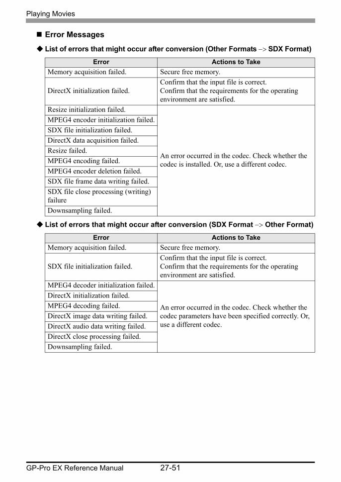
Error Messages
List of errors that might occur after conversion (Other Formats −> SDX Format)
List of errors that might occur after conversion (SDX Format −> Other Format)
Error Actions to TakeMemory acquisition failed. Secure free memory.
DirectX initialization failed.Confirm that the input file is correct.Confirm that the requirements for the operating environment are satisfied.
Resize initialization failed.
An error occurred in the codec. Check whether the codec is installed. Or, use a different codec.
MPEG4 encoder initialization failed.SDX file initialization failed.DirectX data acquisition failed.Resize failed.MPEG4 encoding failed.MPEG4 encoder deletion failed.SDX file frame data writing failed.SDX file close processing (writing) failureDownsampling failed.
Error Actions to TakeMemory acquisition failed. Secure free memory.
SDX file initialization failed.Confirm that the input file is correct.Confirm that the requirements for the operating environment are satisfied.
MPEG4 decoder initialization failed.
An error occurred in the codec. Check whether the codec parameters have been specified correctly. Or, use a different codec.
DirectX initialization failed.MPEG4 decoding failed.DirectX image data writing failed.DirectX audio data writing failed.DirectX close processing failed.Downsampling failed.

Displaying Multiple Video Camera Outputs Simultaneously
GP-Pro EX Reference Manual 27-52
27.6 Displaying Multiple Video Camera Outputs Simultaneously
27.6.1 Introduction
If you install the Video Module Unit on AGP-3500T/3510T/3550T/3560T/3600T/3650T/3750T models, you can display images from up to four video cameras on one screen.It is useful for viewing images from various angles.
• A VM Unit for the GP3000 Series can be installed on the AGP-3750T. For other types, a VM Unit for the GP2000 Series or the GP3000 Series can be installed.
• For the "Video Module unit" specifications and installation method, please refer to the "GP2000 Series Video Module Unit User's Manual" or the "GP3000 Series Video Module Unit User's Manual."
• You can display the PC screen on one of the four split screens."27.7 Displaying PC Screen" (page 27-60)
• You can capture video as still images and save the images in JPEG format."27.8 Saving Video Output as Still Images" (page 27-66)
VM Unit
Camera 2
Camera 1
Camera 3
Camera 4
Camera 3
Camera 2
Camera 4
GP
VM Unit
Display Unit BackCamera 1
Displaying Multiple Video Camera Outputs Simultaneously
GP-Pro EX Reference Manual 27-53
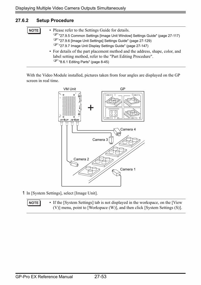
27.6.2 Setup Procedure
With the Video Module installed, pictures taken from four angles are displayed on the GP screen in real time.
1 In [System Settings], select [Image Unit].
• Please refer to the Settings Guide for details."27.9.5 Common Settings [Image Unit Window] Settings Guide" (page 27-117)"27.9.6 [Image Unit Settings] Settings Guide" (page 27-129)"27.9.7 Image Unit Display Settings Guide" (page 27-147)
• For details of the part placement method and the address, shape, color, and label setting method, refer to the "Part Editing Procedure".
"8.6.1 Editing Parts" (page 8-45)
• If the [System Settings] tab is not displayed in the workspace, on the [View (V)] menu, point to [Workspace (W)], and then click [System Settings (S)].
VM Unit
Camera 2
Camera 1
Camera 3
Camera 4
Camera 3
Camera
Camera 4
GPCamera 1
Displaying Multiple Video Camera Outputs Simultaneously
GP-Pro EX Reference Manual 27-54
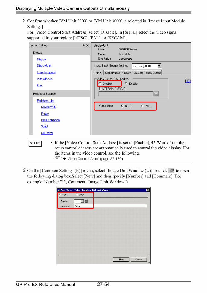
2 Confirm whether [VM Unit 2000] or [VM Unit 3000] is selected in [Image Input Module Settings].For [Video Control Start Address] select [Disable]. In [Signal] select the video signal supported in your region: [NTSC], [PAL], or [SECAM].
3 On the [Common Settings (R)] menu, select [Image Unit Window (U)] or click to open the following dialog box.Select [New] and then specify [Number] and [Comment].(For example, Number "1", Comment "Image Unit Window")
• If the [Video Control Start Address] is set to [Enable], 42 Words from the setup control address are automatically used to control the video display. For the items in the video control, see the following.
" Video Control Area" (page 27-130)
Displaying Multiple Video Camera Outputs Simultaneously
GP-Pro EX Reference Manual 27-55
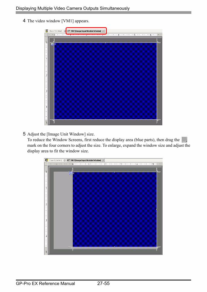
4 The video window [VM1] appears.
5 Adjust the [Image Unit Window] size. To reduce the Window Screens, first reduce the display area (blue parts), then drag the mark on the four corners to adjust the size. To enlarge, expand the window size and adjust the display area to fit the window size.
Displaying Multiple Video Camera Outputs Simultaneously
GP-Pro EX Reference Manual 27-56
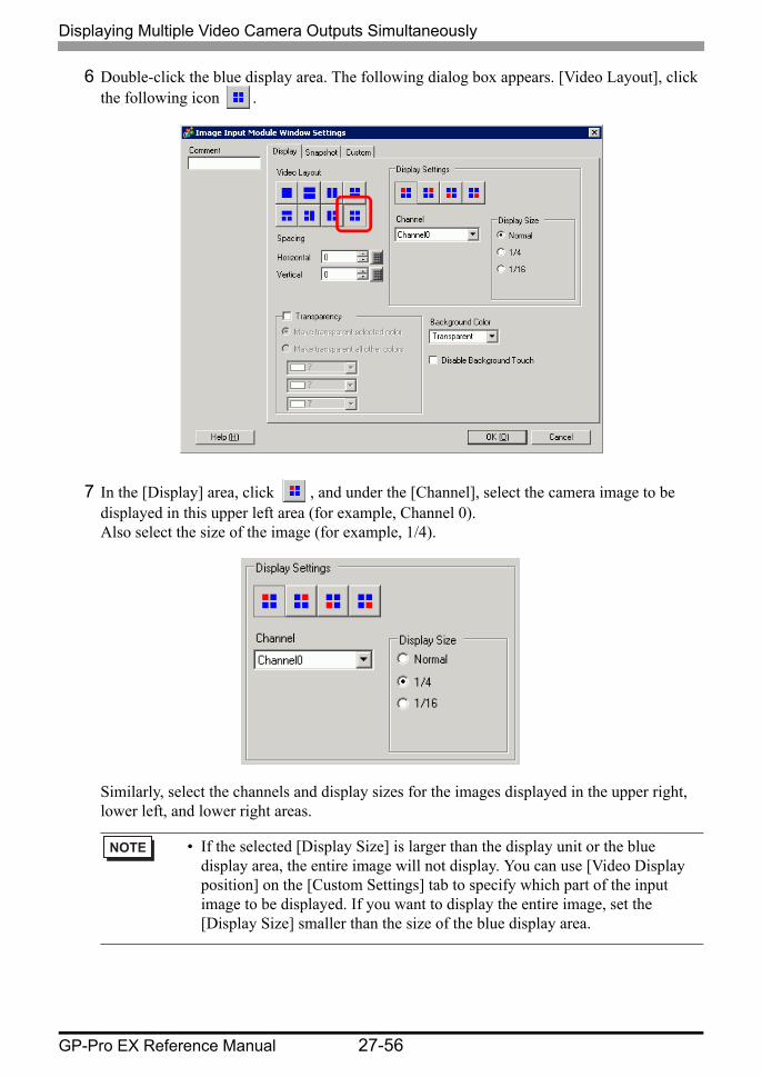
6 Double-click the blue display area. The following dialog box appears. [Video Layout], click the following icon .
7 In the [Display] area, click , and under the [Channel], select the camera image to be displayed in this upper left area (for example, Channel 0). Also select the size of the image (for example, 1/4).
Similarly, select the channels and display sizes for the images displayed in the upper right, lower left, and lower right areas.
• If the selected [Display Size] is larger than the display unit or the blue display area, the entire image will not display. You can use [Video Display position] on the [Custom Settings] tab to specify which part of the input image to be displayed. If you want to display the entire image, set the [Display Size] smaller than the size of the blue display area.

Displaying Multiple Video Camera Outputs Simultaneously
GP-Pro EX Reference Manual 27-57
8 Specify the values for the space between the screens. (For example, Horizontal 10, Vertical 10) Click [OK] to finish and exit the [Image Input Module Window] settings.
9 Click the [Base 1] tab to display the base screen. On the [Parts (P)] menu, select [Image Unit Display (U)] or click to place a [Image Unit Display] on the screen.
Displaying Multiple Video Camera Outputs Simultaneously
GP-Pro EX Reference Manual 27-58
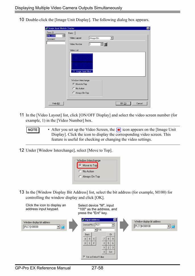
10 Double-click the [Image Unit Display]. The following dialog box appears.
11 In the [Video Layout] list, click [ON/OFF Display] and select the video screen number (for example, 1) in the [Video Number] box.
12 Under [Window Interchange], select [Move to Top].
13 In the [Window Display Bit Address] list, select the bit address (for example, M100) for controlling the window display and click [OK].
• After you set up the Video Screen, the icon appears on the [Image Unit Display]. Click the icon to display the corresponding video screen. This feature is useful for checking or changing the video settings.
Click the icon to display an address input keypad.
Select device "M", input "100" as the address, and press the "Ent" key.
Displaying Multiple Video Camera Outputs Simultaneously
GP-Pro EX Reference Manual 27-59
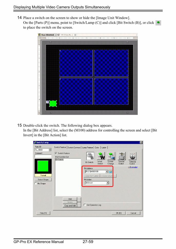
14 Place a switch on the screen to show or hide the [Image Unit Window]. On the [Parts (P)] menu, point to [Switch/Lamp (C)] and click [Bit Switch (B)], or click to place the switch on the screen.
15 Double-click the switch. The following dialog box appears. In the [Bit Address] list, select the (M100) address for controlling the screen and select [Bit Invert] in the [Bit Action] list.
Displaying PC Screen
GP-Pro EX Reference Manual 27-60
27.7 Displaying PC Screen
27.7.1 Introduction
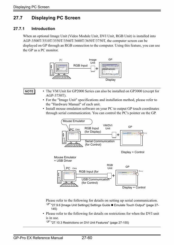
When an optional Image Unit (Video Module Unit, DVI Unit, RGB Unit) is installed into AGP-3500T/3510T/3550T/3560T/3600T/3650T/3750T, the computer screen can be displayed on GP through an RGB connection to the computer. Using this feature, you can use the GP as a PC monitor.
• The VM Unit for GP2000 Series can also be installed on GP3000 (except for AGP-3750T).
• For the "Image Unit" specifications and installation method, please refer to the "Hardware Manual" of each unit.
• Install mouse emulation software on your PC to output GP touch coordinates through serial communication. You can control the PC's pointer on the GP.
Please refer to the following for details on setting up serial communication."27.9.6 [Image Unit Settings] Settings Guide Emulate Touch Output" (page 27-145)
• Please refer to the following for details on restrictions for when the DVI unit is in use.
"27.10.3 Restrictions on DVI Unit Features" (page 27-155)
RGB Input
Image Unit
Display
PC GP
RGB Input (for Display)
VM/DVI Unit
Display + Control
PCGP
Mouse Emulator
Serial Communication (for Control)
Click
Beep
RGB Input (for
RGB Unit
Display + Control
PC GP
Mouse Emulator + USB Driver
USB Communication (for Control)
ClickBeep
Displaying PC Screen
GP-Pro EX Reference Manual 27-61
27.7.2 Setup Procedure
The PC screen is displayed on the screen of the GP with the installed Image Unit.
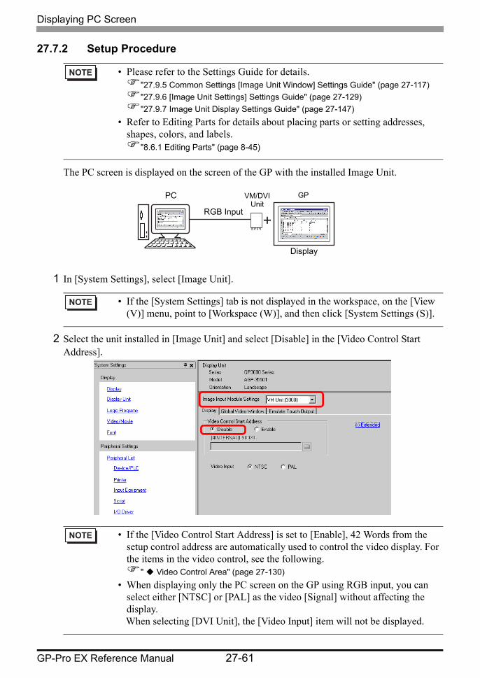
1 In [System Settings], select [Image Unit].
2 Select the unit installed in [Image Unit] and select [Disable] in the [Video Control Start Address].
• Please refer to the Settings Guide for details."27.9.5 Common Settings [Image Unit Window] Settings Guide" (page 27-117)"27.9.6 [Image Unit Settings] Settings Guide" (page 27-129)"27.9.7 Image Unit Display Settings Guide" (page 27-147)
• Refer to Editing Parts for details about placing parts or setting addresses, shapes, colors, and labels.
"8.6.1 Editing Parts" (page 8-45)
• If the [System Settings] tab is not displayed in the workspace, on the [View (V)] menu, point to [Workspace (W)], and then click [System Settings (S)].
• If the [Video Control Start Address] is set to [Enable], 42 Words from the setup control address are automatically used to control the video display. For the items in the video control, see the following.
" Video Control Area" (page 27-130)• When displaying only the PC screen on the GP using RGB input, you can
select either [NTSC] or [PAL] as the video [Signal] without affecting the display. When selecting [DVI Unit], the [Video Input] item will not be displayed.
RGB Input
VM/DVI Unit
Display
PC GP
Displaying PC Screen
GP-Pro EX Reference Manual 27-62
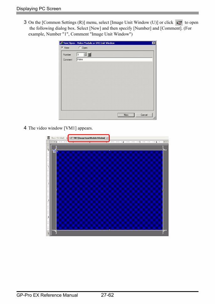
3 On the [Common Settings (R)] menu, select [Image Unit Window (U)] or click to open the following dialog box. Select [New] and then specify [Number] and [Comment]. (For example, Number "1", Comment "Image Unit Window")
4 The video window [VM1] appears.

Displaying PC Screen
GP-Pro EX Reference Manual 27-63
5 Adjust the [Image Unit Window] size. To reduce the Window Screens, first reduce the display area (blue parts), then drag the mark on the four corners to adjust the size. To enlarge, expand the window size and adjust the display area to fit the window size.
6 Double-clicking the display area (the blue part) opens the following dialog box. [Video Layout], click the following icon .
• When selecting [DVI Unit], a portion of the items cannot be set. For more details, please refer to the following.
"27.10.3 Restrictions on DVI Unit Features" (page 27-155)

Displaying PC Screen
GP-Pro EX Reference Manual 27-64
7 In the [Channel] list, select [RGB(IN)] and set the [Display Size] to [Normal].
8 Click [OK] to finish and exit the [Image Unit Window] settings.
9 Click [Base 1] to switch to the base screen. On the [Parts (P)] menu, select [Image Unit Display (U)] or click to place a [Image Unit Display] on the screen.
• If the selected [Display Size] is larger than the display unit or the blue display area, the entire image will not display. You can use [Video Display position] on the [Custom Settings] tab to specify which part of the input image to be displayed. If you want to display the entire image, set the [Display Size] smaller than the size of the blue display area.
• When selecting [DVI Unit], the [Channel] is fixed to [DVI/RGB Input Image].
Displaying PC Screen
GP-Pro EX Reference Manual 27-65
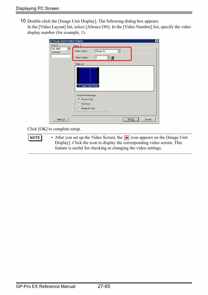
10 Double-click the [Image Unit Display]. The following dialog box appears. In the [Video Layout] list, select [Always ON]. In the [Video Number] list, specify the video display number (for example, 1).
Click [OK] to complete setup.
• After you set up the Video Screen, the icon appears on the [Image Unit Display]. Click the icon to display the corresponding video screen. This feature is useful for checking or changing the video settings.
Saving Video Output as Still Images
GP-Pro EX Reference Manual 27-66
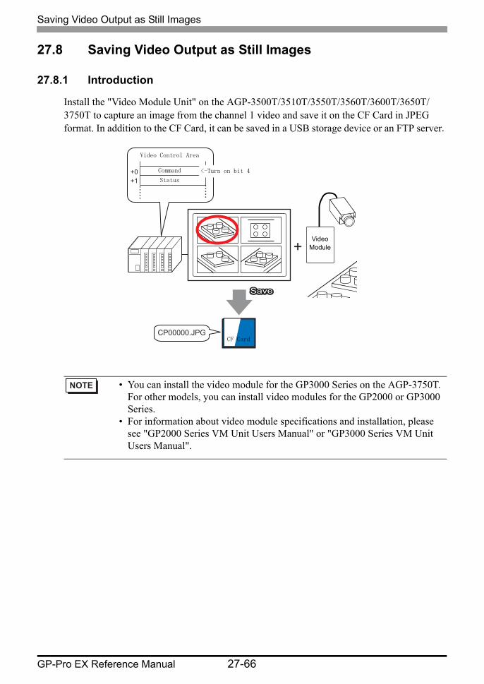
27.8 Saving Video Output as Still Images
27.8.1 Introduction
Install the "Video Module Unit" on the AGP-3500T/3510T/3550T/3560T/3600T/3650T/3750T to capture an image from the channel 1 video and save it on the CF Card in JPEG format. In addition to the CF Card, it can be saved in a USB storage device or an FTP server.
• You can install the video module for the GP3000 Series on the AGP-3750T. For other models, you can install video modules for the GP2000 or GP3000 Series.
• For information about video module specifications and installation, please see "GP2000 Series VM Unit Users Manual" or "GP3000 Series VM Unit Users Manual".
+0+1
CP00000.JPG
Video Control Area
<-Turn on bit 4
SaveSaveSave
CF Card
Command
Status
Video Module

Saving Video Output as Still Images
GP-Pro EX Reference Manual 27-67
27.8.2 Setup Procedure
Turn ON the screen capture address on the PLC side to save the specified image from channel 1 as a still image on a CF card in JPEG format. In addition to the CF card, it can be saved in a USB storage device or an FTP server.
1 In [System Settings], select [Image Unit].
• Please refer to the Settings Guide for details."27.9.6 [Image Unit Settings] Settings Guide" (page 27-129)"27.9.5 Common Settings [Image Unit Window] Settings Guide" (page 27-117)"27.9.7 Image Unit Display Settings Guide" (page 27-147)
• Refer to Editing Parts for details about placing parts or setting addresses, shapes, colors, and labels.
"8.6.1 Editing Parts" (page 8-45)
• If the [System Settings] tab is not displayed in the workspace, on the [View (V)] menu, point to [Workspace (W)], and then click [System Settings (S)].
+0+1
CP00000.JPG
Video Control Area
<-Turn on bit 4
SaveSaveSave
CF Card
Command
Status
Video Module
Saving Video Output as Still Images
GP-Pro EX Reference Manual 27-68
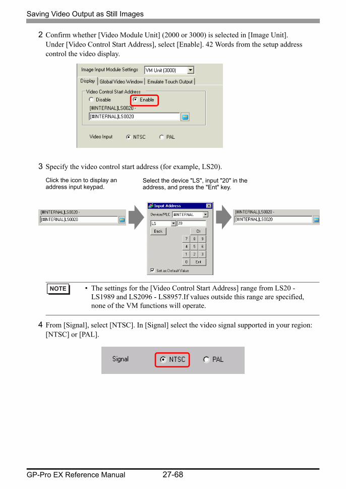
2 Confirm whether [Video Module Unit] (2000 or 3000) is selected in [Image Unit].Under [Video Control Start Address], select [Enable]. 42 Words from the setup address control the video display.
3 Specify the video control start address (for example, LS20).
4 From [Signal], select [NTSC]. In [Signal] select the video signal supported in your region: [NTSC] or [PAL].
• The settings for the [Video Control Start Address] range from LS20 - LS1989 and LS2096 - LS8957.If values outside this range are specified, none of the VM functions will operate.
Click the icon to display an address input keypad.
Select the device "LS", input "20" in the address, and press the "Ent" key.
Saving Video Output as Still Images
GP-Pro EX Reference Manual 27-69
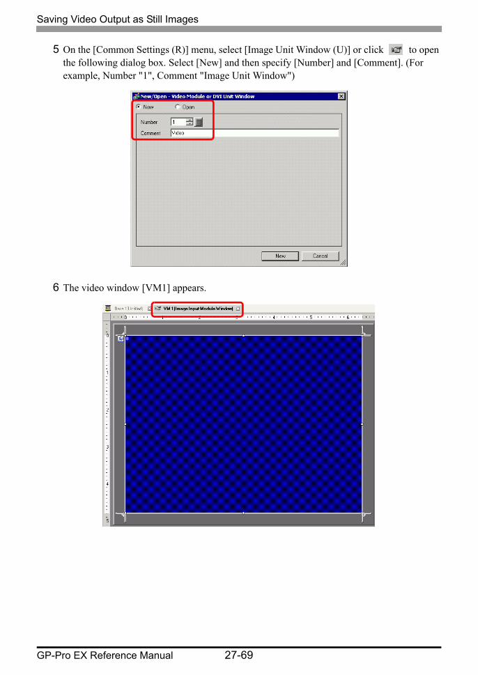
5 On the [Common Settings (R)] menu, select [Image Unit Window (U)] or click to open the following dialog box. Select [New] and then specify [Number] and [Comment]. (For example, Number "1", Comment "Image Unit Window")
6 The video window [VM1] appears.
Saving Video Output as Still Images
GP-Pro EX Reference Manual 27-70
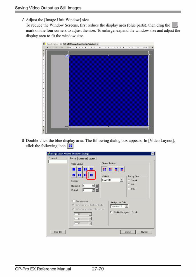
7 Adjust the [Image Unit Window] size. To reduce the Window Screens, first reduce the display area (blue parts), then drag the mark on the four corners to adjust the size. To enlarge, expand the window size and adjust the display area to fit the window size.
8 Double-click the blue display area. The following dialog box appears. In [Video Layout], click the following icon .

Saving Video Output as Still Images
GP-Pro EX Reference Manual 27-71
9 In the [Display] area, click , and under the [Channel], select the camera image to be displayed in this upper left area (for example, Channel 0). Also select the size of the image (for example, 1/4).
Similarly, select the channels and display sizes for the images displayed in the upper right, lower left, and lower right areas.
10 Specify the values for the space between the screens. (For example, Horizontal 10, Vertical 10). Click [OK] to finish and exit the [Image Unit Window] settings.
11 Open the [Snapshot] tab, and select the [Video capture] check box.
12 In the [Channel] list, select [Channel 0].
13 Under [JPG File Number], select [Direct], and specify the JPEG file number for the file you are creating.
14 Click [OK] to finish and exit [Image Unit Window].
• If the selected [Display Size] is larger than the display unit or the blue display area, the entire image will not display. You can use [Video Display position] on the [Custom Settings] tab to specify which part of the input image to be displayed. If you want to display the entire image, set the [Display Size] smaller than the size of the blue display area.
• You can capture screens for one channel only. You can capture screens only for video images.
• Other than the CF card, you can also save to a USB storage device or an FTP server.In the system settings, select [Display Unit] and click the [Mode] tab. In [Screen Capture Settings], select the [Capture Action] check box to select the location to save the file in.
Saving Video Output as Still Images
GP-Pro EX Reference Manual 27-72
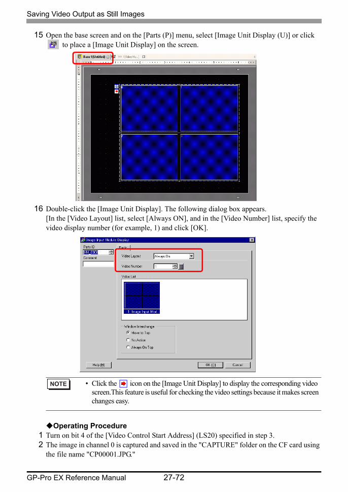
15 Open the base screen and on the [Parts (P)] menu, select [Image Unit Display (U)] or click to place a [Image Unit Display] on the screen.
16 Double-click the [Image Unit Display]. The following dialog box appears. [In the [Video Layout] list, select [Always ON], and in the [Video Number] list, specify the video display number (for example, 1) and click [OK].
Operating Procedure
1 Turn on bit 4 of the [Video Control Start Address] (LS20) specified in step 3.2 The image in channel 0 is captured and saved in the "CAPTURE" folder on the CF card using
the file name "CP00001.JPG."
• Click the icon on the [Image Unit Display] to display the corresponding video screen.This feature is useful for checking the video settings because it makes screen changes easy.
Settings Guide
GP-Pro EX Reference Manual 27-73
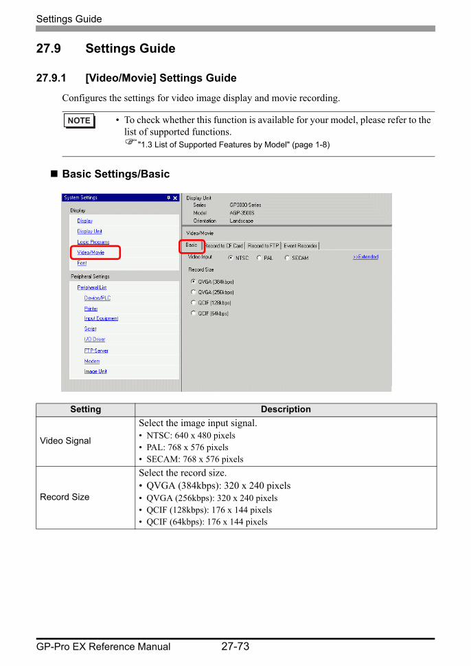
27.9 Settings Guide
27.9.1 [Video/Movie] Settings Guide
Configures the settings for video image display and movie recording.
Basic Settings/Basic
• To check whether this function is available for your model, please refer to the list of supported functions.
"1.3 List of Supported Features by Model" (page 1-8)
Setting Description
Video Signal
Select the image input signal.• NTSC: 640 x 480 pixels• PAL: 768 x 576 pixels• SECAM: 768 x 576 pixels
Record Size
Select the record size.• QVGA (384kbps): 320 x 240 pixels• QVGA (256kbps): 320 x 240 pixels• QCIF (128kbps): 176 x 144 pixels• QCIF (64kbps): 176 x 144 pixels
Settings Guide
GP-Pro EX Reference Manual 27-74
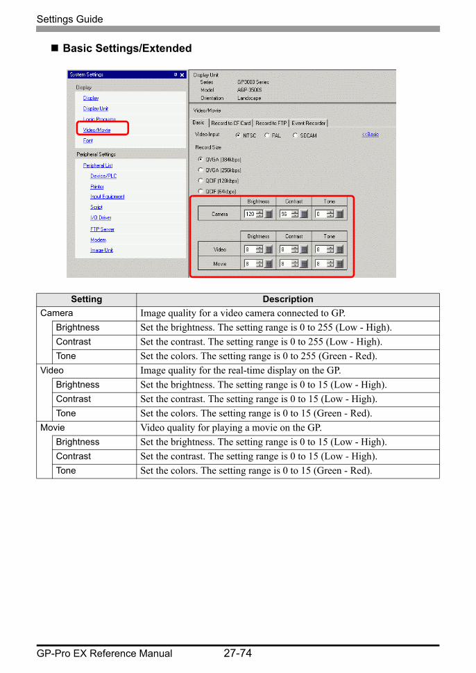
Basic Settings/Extended
Setting DescriptionCamera Image quality for a video camera connected to GP.
Brightness Set the brightness. The setting range is 0 to 255 (Low - High).Contrast Set the contrast. The setting range is 0 to 255 (Low - High).Tone Set the colors. The setting range is 0 to 255 (Green - Red).
Video Image quality for the real-time display on the GP.Brightness Set the brightness. The setting range is 0 to 15 (Low - High).Contrast Set the contrast. The setting range is 0 to 15 (Low - High).Tone Set the colors. The setting range is 0 to 15 (Green - Red).
Movie Video quality for playing a movie on the GP.Brightness Set the brightness. The setting range is 0 to 15 (Low - High).Contrast Set the contrast. The setting range is 0 to 15 (Low - High).Tone Set the colors. The setting range is 0 to 15 (Green - Red).
Settings Guide
GP-Pro EX Reference Manual 27-75
Record CF
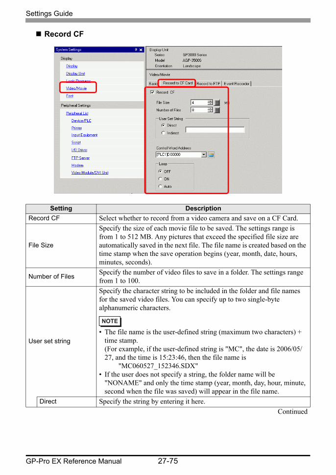
Setting DescriptionRecord CF Select whether to record from a video camera and save on a CF Card.
File Size
Specify the size of each movie file to be saved. The settings range is from 1 to 512 MB. Any pictures that exceed the specified file size are automatically saved in the next file. The file name is created based on the time stamp when the save operation begins (year, month, date, hours, minutes, seconds).
Number of Files Specify the number of video files to save in a folder. The settings range from 1 to 100.
User set string
Specify the character string to be included in the folder and file names for the saved video files. You can specify up to two single-byte alphanumeric characters.
• The file name is the user-defined string (maximum two characters) + time stamp. (For example, if the user-defined string is "MC", the date is 2006/05/27, and the time is 15:23:46, then the file name is
"MC060527_152346.SDX"• If the user does not specify a string, the folder name will be
"NONAME" and only the time stamp (year, month, day, hour, minute, second when the file was saved) will appear in the file name.
Direct Specify the string by entering it here.Continued
Settings Guide
GP-Pro EX Reference Manual 27-76
Use
r Set
Stri
ng
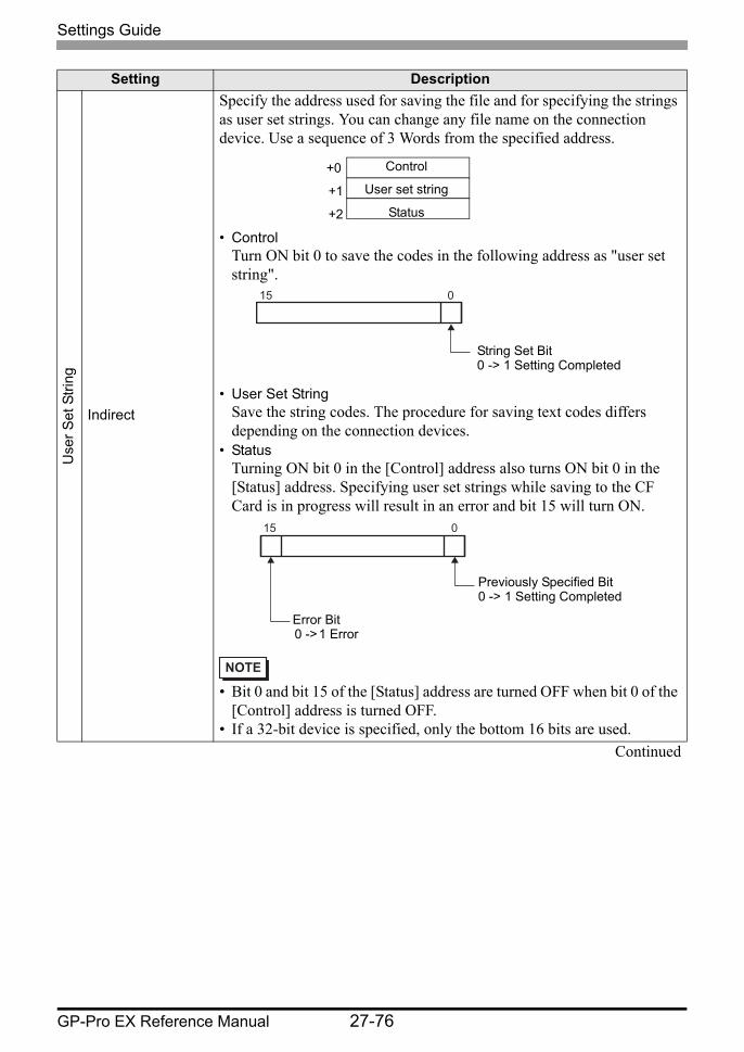
Indirect
Specify the address used for saving the file and for specifying the strings as user set strings. You can change any file name on the connection device. Use a sequence of 3 Words from the specified address.
• ControlTurn ON bit 0 to save the codes in the following address as "user set string".
• User Set StringSave the string codes. The procedure for saving text codes differs depending on the connection devices.
• StatusTurning ON bit 0 in the [Control] address also turns ON bit 0 in the [Status] address. Specifying user set strings while saving to the CF Card is in progress will result in an error and bit 15 will turn ON.
• Bit 0 and bit 15 of the [Status] address are turned OFF when bit 0 of the [Control] address is turned OFF.
• If a 32-bit device is specified, only the bottom 16 bits are used.Continued
Setting Description
Control
User set string
Status
+0
+1
+2
015
String Set Bit0 -> 1 Setting Completed
015
Previously Specified Bit0 -> 1 Setting Completed
Error Bit0 -> 1 Error
Settings Guide
GP-Pro EX Reference Manual 27-77
Control Word Address
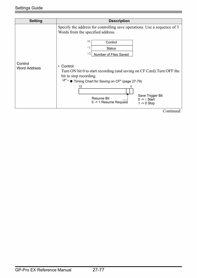
Specify the address for controlling save operations. Use a sequence of 3 Words from the specified address.
• ControlTurn ON bit 0 to start recording (and saving on CF Card).Turn OFF the bit to stop recording.
" Timing Chart for Saving on CF" (page 27-79)
Continued
Setting Description
Control
Status
Number of Files Saved
+0
+1
+2
0 15
Save Trigger Bit0 -> 1 Start1 -> 0 Stop
Resume Bit0 -> 1 Resume Request
Settings Guide
GP-Pro EX Reference Manual 27-78
Control Word Address
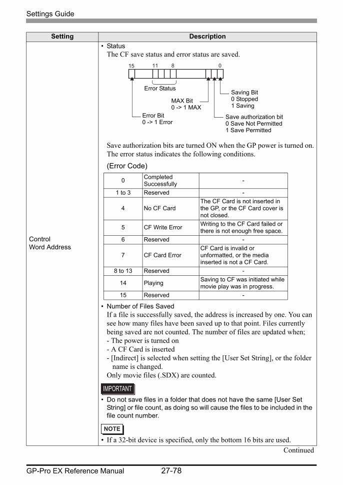
• StatusThe CF save status and error status are saved.
Save authorization bits are turned ON when the GP power is turned on.The error status indicates the following conditions.(Error Code)
• Number of Files SavedIf a file is successfully saved, the address is increased by one. You can see how many files have been saved up to that point. Files currently being saved are not counted. The number of files are updated when;- The power is turned on- A CF Card is inserted- [Indirect] is selected when setting the [User Set String], or the folder
name is changed.Only movie files (.SDX) are counted.
• Do not save files in a folder that does not have the same [User Set String] or file count, as doing so will cause the files to be included in the file count number.
• If a 32-bit device is specified, only the bottom 16 bits are used.Continued
Setting Description
081115
Saving Bit0 Stopped1 Saving
Save authorization bit0 Save Not Permitted1 Save Permitted
MAX Bit0 -> 1 MAX
Error Bit0 -> 1 Error
Error Status
0 Completed Successfully -
1 to 3 Reserved -
4 No CF CardThe CF Card is not inserted in the GP, or the CF Card cover is not closed.
5 CF Write Error Writing to the CF Card failed or there is not enough free space.
6 Reserved -
7 CF Card ErrorCF Card is invalid or unformatted, or the media inserted is not a CF Card.
8 to 13 Reserved -
14 Playing Saving to CF was initiated while movie play was in progress.
15 Reserved -

Settings Guide
GP-Pro EX Reference Manual 27-79
Timing Chart for Saving on CF
Loop Set the operation to be initiated after the movie files have been saved as specified in [Number of Files].
Disable
After all the specified files have been saved (the MAX bit is turned ON), no more files can be saved. To resume saving, delete movie files or specify files saved in another folder and turn ON the resume bit. The MAX bit turns OFF.
EnableAfter all the specified files have been saved (the MAX bit is turned ON), no more files can be saved. When the resume bit is turned ON, the oldest file is deleted and a new file is saved.
Auto Once all the specified files have been saved (the MAX bit is turned ON), the files are deleted starting with the oldest file, and new files are saved.
• Bit 1 (resume bit) of the [Control] address does not automatically turn OFF. Confirm that bit 2 (MAX bit) of the [Status] address is tuned OFF and then turn OFF the resume bit.
Setting Description
Resume Bit (PLC -> GP)
MAX Bit (GP -> PLC)
Save Trigger (PLC -> GP)Save Authorization (GP -> PLC)Data Save(GP -> CF)
Saving (GP -> PLC)
Settings Guide
GP-Pro EX Reference Manual 27-80
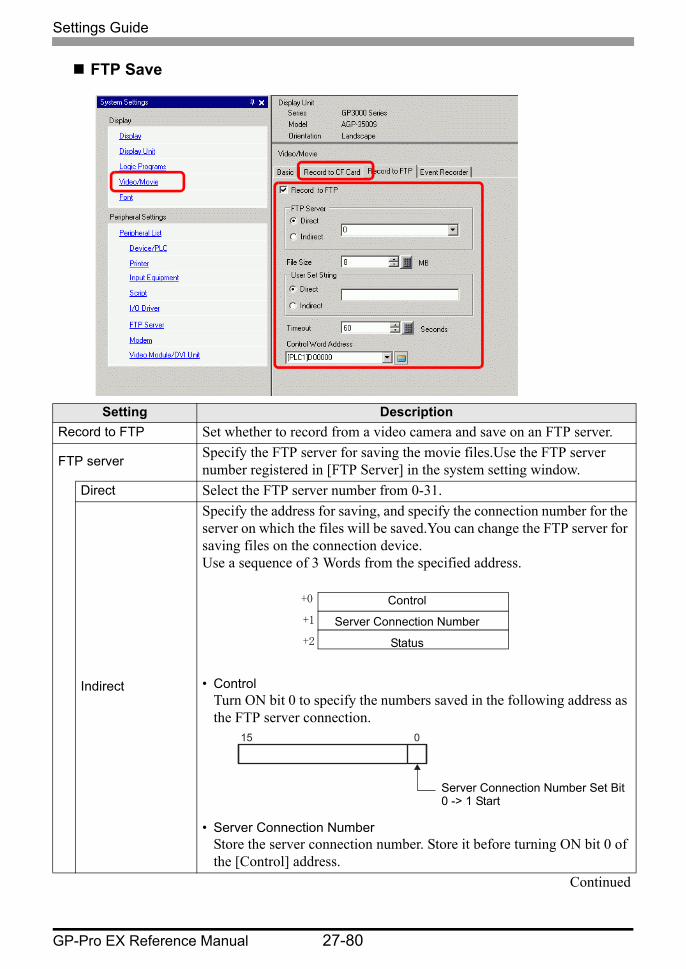
FTP Save
Setting DescriptionRecord to FTP Set whether to record from a video camera and save on an FTP server.
FTP server Specify the FTP server for saving the movie files.Use the FTP server number registered in [FTP Server] in the system setting window.
Direct Select the FTP server number from 0-31.
Indirect
Specify the address for saving, and specify the connection number for the server on which the files will be saved.You can change the FTP server for saving files on the connection device.Use a sequence of 3 Words from the specified address.
• ControlTurn ON bit 0 to specify the numbers saved in the following address as the FTP server connection.
• Server Connection NumberStore the server connection number. Store it before turning ON bit 0 of the [Control] address.
Continued
Control
Server Connection Number
Status
+0
+1
+2
015
Server Connection Number Set Bit0 -> 1 Start
Settings Guide
GP-Pro EX Reference Manual 27-81
FTP
Ser
ver
Indirect
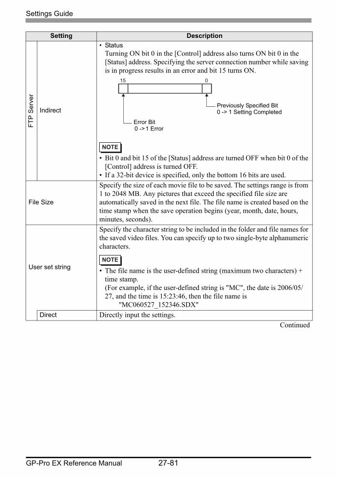
• StatusTurning ON bit 0 in the [Control] address also turns ON bit 0 in the [Status] address. Specifying the server connection number while saving is in progress results in an error and bit 15 turns ON.
• Bit 0 and bit 15 of the [Status] address are turned OFF when bit 0 of the [Control] address is turned OFF.
• If a 32-bit device is specified, only the bottom 16 bits are used.
File Size
Specify the size of each movie file to be saved. The settings range is from 1 to 2048 MB. Any pictures that exceed the specified file size are automatically saved in the next file. The file name is created based on the time stamp when the save operation begins (year, month, date, hours, minutes, seconds).
User set string
Specify the character string to be included in the folder and file names for the saved video files. You can specify up to two single-byte alphanumeric characters.
• The file name is the user-defined string (maximum two characters) + time stamp. (For example, if the user-defined string is "MC", the date is 2006/05/27, and the time is 15:23:46, then the file name is
"MC060527_152346.SDX"Direct Directly input the settings.
Continued
Setting Description
015
Previously Specified Bit0 -> 1 Setting Completed
Error Bit0 -> 1 Error

Settings Guide
GP-Pro EX Reference Manual 27-82
Use
r Set
Stri
ng
Indirect
Specify the address used for saving the file and for specifying the strings as user set strings. You can change any file name on the connection device. Use a sequence of three Words from the specified address.
• ControlTurn ON bit 0 to save the codes in the following address as "user set string".
• User Set StringSave the string codes. The procedure for saving text codes differs depending on the connection devices.
Indirect
• StatusTurning ON bit 0 in the [Control] address also turns ON bit 0 in the [Status] address.Specifying user set strings while saving is in progress results in an error and bit 15 turns ON.
• Bit 0 and bit 15 of the [Status] address are turned OFF when bit 0 of the [Control] address is turned OFF.
• If a 32-bit device is specified, only the bottom 16 bits are used.
Time out Specify the queuing time for when the FTP server does not respond to an access request.The value can be from 10 to 120 seconds.
Continued
Setting Description
Control
User set string
Status
+0
+1
+2
015
String Set Bit0 -> 1 Setting Completed
015
Previously Specified Bit0 -> 1 Setting Completed
Error Bit0 -> 1 Error

Settings Guide
GP-Pro EX Reference Manual 27-83
Control Word Address
Specify the address for controlling save operations. Use a sequence of two words from the specified address.
• ControlTurn ON bit 0 to start recording (start saving to FTP). Turn OFF the bit to stop recording." Timing Chart for Saving to FTP" (page 27-84)
Control Word Address
• StatusThe FTP save and error status are saved.
Save authorization bits are turned ON when the GP power is turned on.The error status indicates the following conditions.(Error Code)
• If a 32-bit device is specified, only the bottom 16 bits are used.
Setting Description
Control
Status+0
+1
0 15
Save Trigger Bit0 -> 1 Start1 −> 0 Stop
Resume Bit0 -> 1 Resume Request
0811 15
Saving Bit0 Stopped1 Saving
Save authorization bit0 Save Not Permitted1 Save Permitted
Error Bit0 -> 1 Error
Error Status
0 Completed Successfully -1 to 8 Reserved -
9 FTP Connection ErrorThe FTP server is not operating normally, or the FTP server does not exist.
10 FTP Login Error The FTP user name or password is incorrect.
11 Write Error
The logged in user does not have writing privileges, or writing to the FTP server has failed, or there is not enough free space.
12 to 13 Reserved -
14 Client functions are operating
Saving to FTP server was initiated while movie play was in progress.
15 Reserved -
Settings Guide
GP-Pro EX Reference Manual 27-84
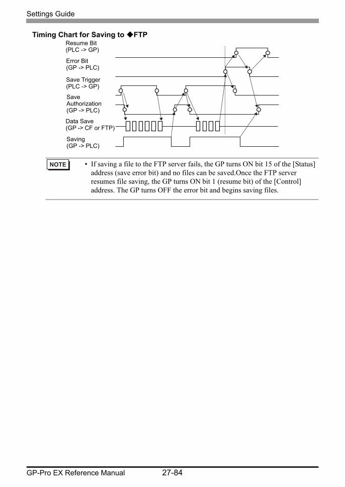
Timing Chart for Saving to FTP
• If saving a file to the FTP server fails, the GP turns ON bit 15 of the [Status] address (save error bit) and no files can be saved.Once the FTP server resumes file saving, the GP turns ON bit 1 (resume bit) of the [Control] address. The GP turns OFF the error bit and begins saving files.
Resume Bit(PLC -> GP)
Error Bit(GP -> PLC)
Save Trigger(PLC -> GP)
Save Authorization(GP -> PLC)
Data Save(GP -> CF or FTP)
Saving(GP -> PLC)
Settings Guide
GP-Pro EX Reference Manual 27-85
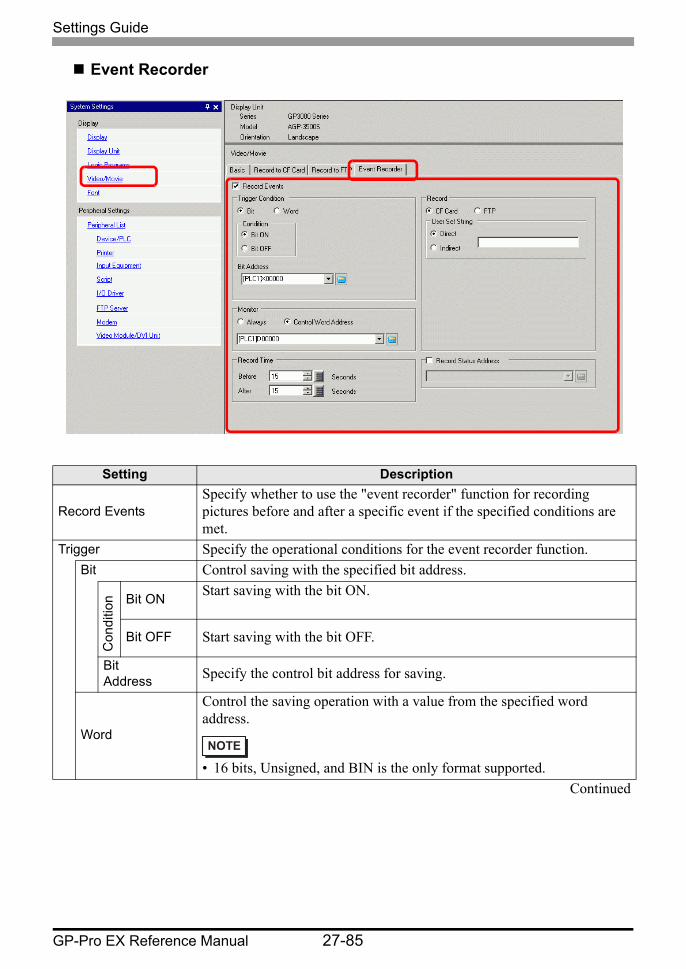
Event Recorder
Setting Description
Record EventsSpecify whether to use the "event recorder" function for recording pictures before and after a specific event if the specified conditions are met.
Trigger Specify the operational conditions for the event recorder function.Bit Control saving with the specified bit address.
Con
ditio
n Bit ON Start saving with the bit ON.
Bit OFF Start saving with the bit OFF.
BitAddress Specify the control bit address for saving.
Word
Control the saving operation with a value from the specified word address.
• 16 bits, Unsigned, and BIN is the only format supported.Continued
Settings Guide
GP-Pro EX Reference Manual 27-86
Trig
ger
Wor
d
Con
ditio
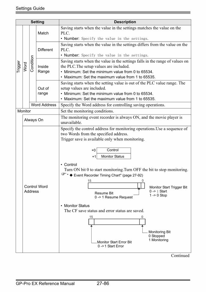
nMatch
Saving starts when the value in the settings matches the value on the PLC.• Number: Specify the value in the settings.
DifferentSaving starts when the value in the settings differs from the value on the PLC.• Number: Specify the value in the settings.
Inside Range
Saving starts when the value in the settings falls in the range of values on the PLC.The setup values are included.• Minimum: Set the minimum value from 0 to 65534.• Maximum: Set the maximum value from 1 to 65535.
Out of range
Saving starts when the setting value is out of the PLC value range. The setup values are included.• Minimum: Set the minimum value from 0 to 65534.• Maximum: Set the maximum value from 1 to 65535.
Word Address Specify the Word address for controlling saving operations.Monitor Set the monitoring conditions.
Always On The monitoring event recorder is always ON, and the movie player is unavailable.
Control Word Address
Specify the control address for monitoring operations.Use a sequence of two Words from the specified address.Trigger save is available only when monitoring.
• ControlTurn ON bit 0 to start monitoring.Turn OFF the bit to stop monitoring.
" Event Recorder Timing Chart" (page 27-92)
• Monitor StatusThe CF save status and error status are saved.
Continued
Setting Description
Control
Monitor Status
+0
+1
0 15
Monitor Start Trigger Bit0 -> 1 Start1 -> 0 StopResume Bit
0 -> 1 Resume Request
015
Monitoring Bit0 Stopped1 MonitoringMonitor Start Error Bit
0 -> 1 Start Error
Settings Guide
GP-Pro EX Reference Manual 27-87
Record Time
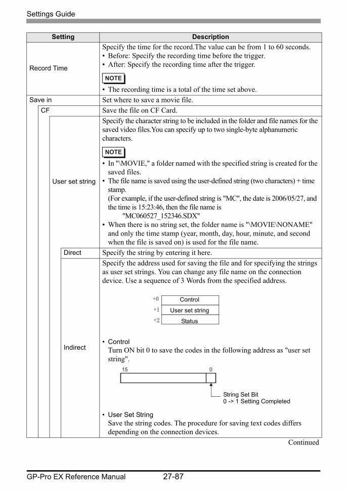
Specify the time for the record.The value can be from 1 to 60 seconds.• Before: Specify the recording time before the trigger.• After: Specify the recording time after the trigger.
• The recording time is a total of the time set above.Save in Set where to save a movie file.
CF Save the file on CF Card.
User set string
Specify the character string to be included in the folder and file names for the saved video files.You can specify up to two single-byte alphanumeric characters.
• In "\MOVIE," a folder named with the specified string is created for the saved files.
• The file name is saved using the user-defined string (two characters) + time stamp. (For example, if the user-defined string is "MC", the date is 2006/05/27, and the time is 15:23:46, then the file name is
"MC060527_152346.SDX"• When there is no string set, the folder name is "\MOVIE\NONAME"
and only the time stamp (year, month, day, hour, minute, and second when the file is saved on) is used for the file name.
Direct Specify the string by entering it here.
Indirect
Specify the address used for saving the file and for specifying the strings as user set strings. You can change any file name on the connection device. Use a sequence of 3 Words from the specified address.
• ControlTurn ON bit 0 to save the codes in the following address as "user set string".
• User Set StringSave the string codes. The procedure for saving text codes differs depending on the connection devices.
Continued
Setting Description
Control
User set string
Status
+0
+1
+2
015
String Set Bit0 -> 1 Setting Completed
Settings Guide
GP-Pro EX Reference Manual 27-88
Sav
e in
CF
Use
r Set
Stri
ng
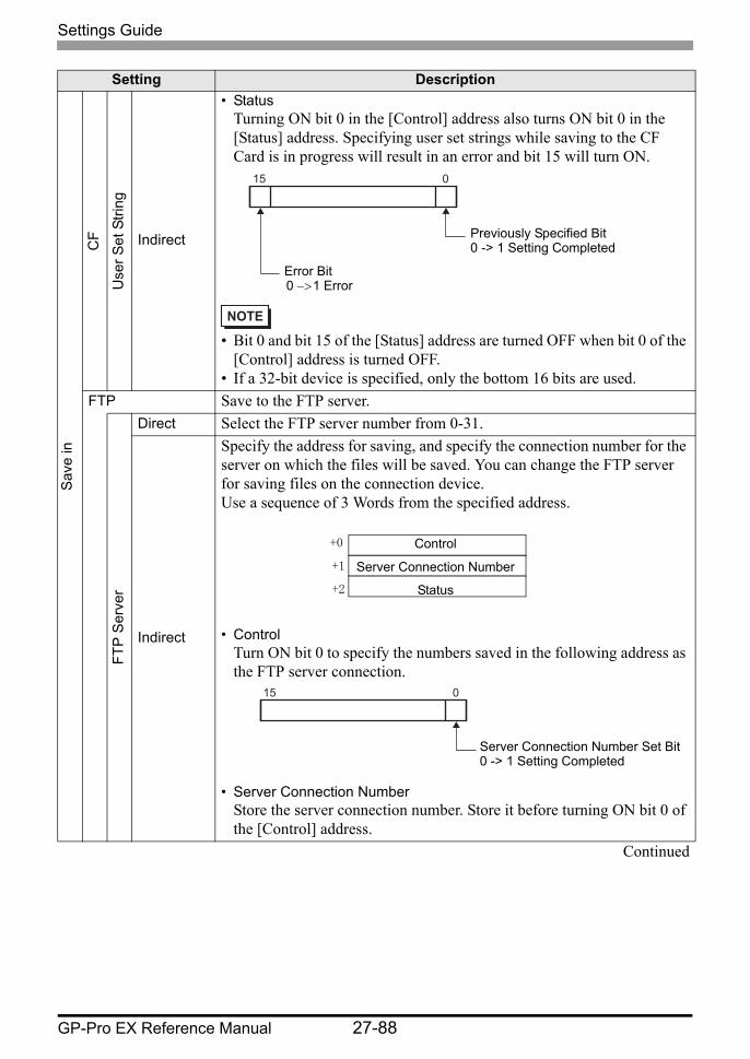
Indirect
• StatusTurning ON bit 0 in the [Control] address also turns ON bit 0 in the [Status] address. Specifying user set strings while saving to the CF Card is in progress will result in an error and bit 15 will turn ON.
• Bit 0 and bit 15 of the [Status] address are turned OFF when bit 0 of the [Control] address is turned OFF.
• If a 32-bit device is specified, only the bottom 16 bits are used.FTP Save to the FTP server.
FTP
Ser
ver
Direct Select the FTP server number from 0-31.
Indirect
Specify the address for saving, and specify the connection number for the server on which the files will be saved. You can change the FTP server for saving files on the connection device.Use a sequence of 3 Words from the specified address.
• ControlTurn ON bit 0 to specify the numbers saved in the following address as the FTP server connection.
• Server Connection NumberStore the server connection number. Store it before turning ON bit 0 of the [Control] address.
Continued
Setting Description
015
Previously Specified Bit0 -> 1 Setting Completed
Error Bit0 −> 1 Error
Control
Server Connection Number
Status
+0
+1
+2
015
Server Connection Number Set Bit0 -> 1 Setting Completed
Settings Guide
GP-Pro EX Reference Manual 27-89
Sav
e in
FTP
FTP
Ser
ver
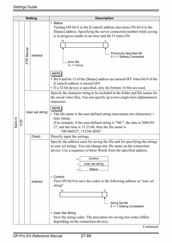
Indirect
• StatusTurning ON bit 0 in the [Control] address also turns ON bit 0 in the [Status] address. Specifying the server connection number while saving is in progress results in an error and bit 15 turns ON.
• Bit 0 and bit 15 of the [Status] address are turned OFF when bit 0 of the [Control] address is turned OFF.
• If a 32-bit device is specified, only the bottom 16 bits are used.
User set string
Specify the character string to be included in the folder and file names for the saved video files. You can specify up to two single-byte alphanumeric characters.
• The file name is the user-defined string (maximum two characters) + time stamp. (For example, if the user-defined string is "MC", the date is 2006/05/27, and the time is 15:23:46, then the file name is
"MC060527_152346.SDX"Direct Directly input the settings.
Indirect
Specify the address used for saving the file and for specifying the strings as user set strings. You can change any file name on the connection device. Use a sequence of three Words from the specified address.
• ControlTurn ON bit 0 to save the codes in the following address as "user set string".
• User Set StringSave the string codes. The procedure for saving text codes differs depending on the connection devices.
Continued
Setting Description
015
Previously Specified Bit0 -> 1 Setting Completed
Error Bit0 -> 1 Error
Control
User set string
Status
+0
+1
+2
015
String Set Bit0 -> 1 Setting Completed
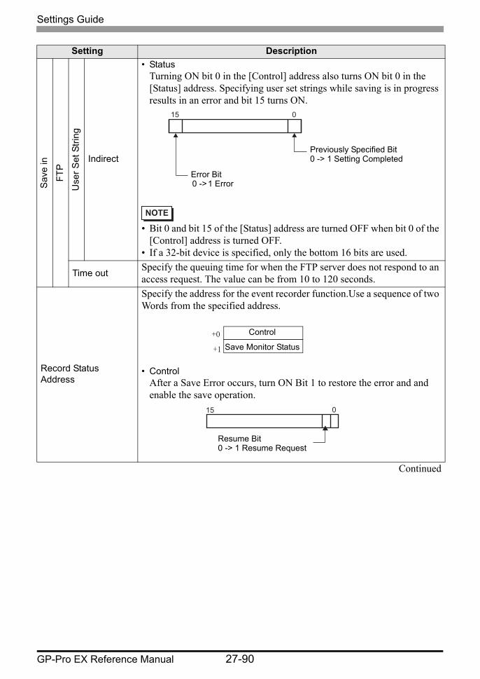
Settings Guide
GP-Pro EX Reference Manual 27-90
Sav
e in
FTP
Use
r Set
Stri
ng
Indirect
• StatusTurning ON bit 0 in the [Control] address also turns ON bit 0 in the [Status] address. Specifying user set strings while saving is in progress results in an error and bit 15 turns ON.
• Bit 0 and bit 15 of the [Status] address are turned OFF when bit 0 of the [Control] address is turned OFF.
• If a 32-bit device is specified, only the bottom 16 bits are used.
Time out Specify the queuing time for when the FTP server does not respond to an access request. The value can be from 10 to 120 seconds.
Record Status Address
Specify the address for the event recorder function.Use a sequence of two Words from the specified address.
• ControlAfter a Save Error occurs, turn ON Bit 1 to restore the error and and enable the save operation.
Continued
Setting Description
015
Previously Specified Bit0 -> 1 Setting Completed
Error Bit0 -> 1 Error
Control
Save Monitor Status+0
+1
015
Resume Bit0 -> 1 Resume Request
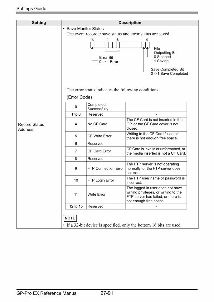
Settings Guide
GP-Pro EX Reference Manual 27-91
Record Status Address
• Save Monitor StatusThe event recorder save status and error status are saved.
The error status indicates the following conditions.(Error Code)
• If a 32-bit device is specified, only the bottom 16 bits are used.
Setting Description
081115
FileOutputting Bit0 Stopped1 Saving
Save Completed Bit0 ->1 Save Completed
Error Bit0 -> 1 Error
0 Completed Successfully -
1 to 3 Reserved -
4 No CF CardThe CF Card is not inserted in the GP, or the CF Card cover is not closed.
5 CF Write Error Writing to the CF Card failed or there is not enough free space.
6 Reserved -
7 CF Card Error CF Card is invalid or unformatted, or the media inserted is not a CF Card.
8 Reserved -
9 FTP Connection ErrorThe FTP server is not operating normally, or the FTP server does not exist.
10 FTP Login Error The FTP user name or password is incorrect.
11 Write Error
The logged in user does not have writing privileges, or writing to the FTP server has failed, or there is not enough free space.
12 to 15 Reserved -
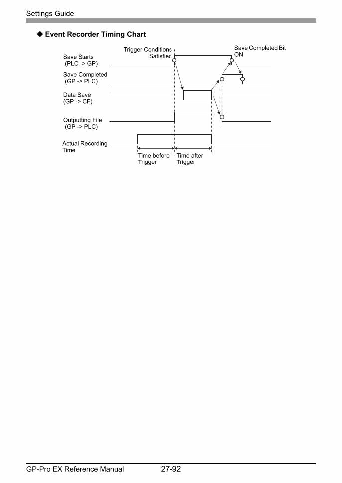
Settings Guide
GP-Pro EX Reference Manual 27-92
Event Recorder Timing Chart
Save Starts (PLC -> GP)
Save Completed (GP -> PLC)
Data Save(GP -> CF)
Outputting File (GP -> PLC)
Actual Recording Time
Time before Trigger
Time after Trigger
Trigger Conditions Satisfied
Save Completed Bit ON

Settings Guide
GP-Pro EX Reference Manual 27-93
27.9.2 [FTP Server] Settings Guide
Setting DescriptionCreate Display the [FTP Server] dialog box.Edit Edit the registered contents.Copy Copy the registered contents from the selected row.Paste Paste the copied registered contents to the selected row in the list.Delete Delete the selected row.
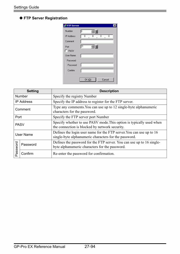
Settings Guide
GP-Pro EX Reference Manual 27-94
FTP Server Registration
Setting DescriptionNumber Specify the registry NumberIP Address Specify the IP address to register for the FTP server.
Comment Type any comments.You can use up to 12 single-byte alphanumeric characters for the password.
Port Specify the FTP server port Number
PASV Specify whether to use PASV mode.This option is typically used when the connection is blocked by network security.
User Name Defines the login user name for the FTP server.You can use up to 16 single-byte alphanumeric characters for the password.
Pas
swor
d
Password Defines the password for the FTP server. You can use up to 16 single-byte alphanumeric characters for the password.
Confirm Re-enter the password for confirmation.
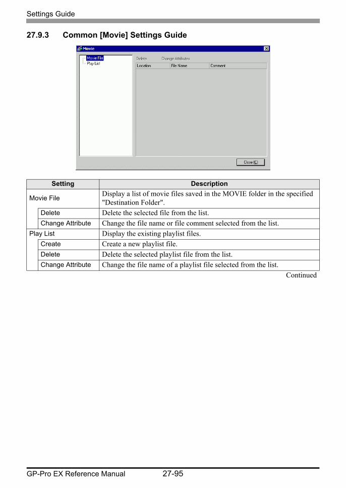
Settings Guide
GP-Pro EX Reference Manual 27-95
27.9.3 Common [Movie] Settings Guide
Setting Description
Movie File Display a list of movie files saved in the MOVIE folder in the specified "Destination Folder".
Delete Delete the selected file from the list.Change Attribute Change the file name or file comment selected from the list.
Play List Display the existing playlist files.Create Create a new playlist file.Delete Delete the selected playlist file from the list.Change Attribute Change the file name of a playlist file selected from the list.
Continued
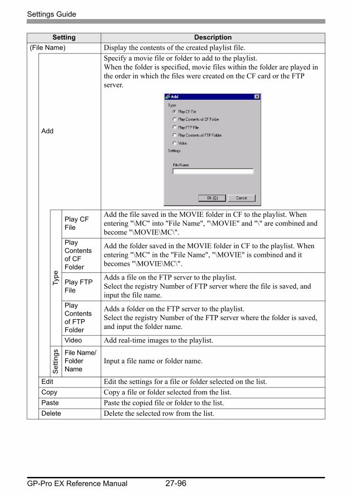
Settings Guide
GP-Pro EX Reference Manual 27-96
(File Name) Display the contents of the created playlist file.
Add
Specify a movie file or folder to add to the playlist.When the folder is specified, movie files within the folder are played in the order in which the files were created on the CF card or the FTP server.
Type
Play CF File
Add the file saved in the MOVIE folder in CF to the playlist. When entering "\MC" into "File Name", "\MOVIE" and "\" are combined and become "\MOVIE\MC\".
Play Contents of CF Folder
Add the folder saved in the MOVIE folder in CF to the playlist. When entering "\MC" in the "File Name", "\MOVIE" is combined and it becomes "\MOVIE\MC\".
Play FTP File
Adds a file on the FTP server to the playlist.Select the registry Number of FTP server where the file is saved, and input the file name.
Play Contents of FTP Folder
Adds a folder on the FTP server to the playlist.Select the registry Number of the FTP server where the folder is saved, and input the folder name.
Video Add real-time images to the playlist.
Set
tings File Name/
Folder Name
Input a file name or folder name.
Edit Edit the settings for a file or folder selected on the list.Copy Copy a file or folder selected from the list.Paste Paste the copied file or folder to the list.Delete Delete the selected row from the list.
Setting Description

Settings Guide
GP-Pro EX Reference Manual 27-97
27.9.4 [Movie Player] Settings Guide
This is a component used for playing movies.Use it for displaying images from video cameras and for playing movie files. You can place only one player on a screen.
Setting Description
Part ID
Placed parts are assigned an ID number.Part ID of Movie Player: MV_∗∗∗∗ (four digit number)The letter portion is fixed.You can change the number portion within the range of 0000-9999.
Comment The comment for each Part can be up to 20 characters.
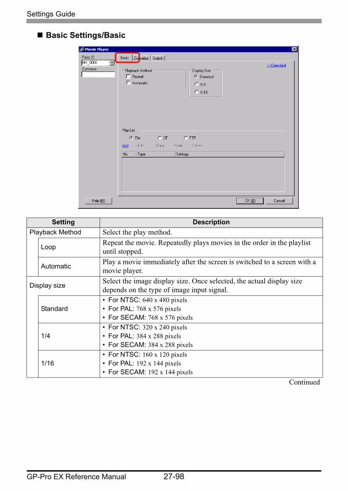
Settings Guide
GP-Pro EX Reference Manual 27-98
Basic Settings/Basic
Setting DescriptionPlayback Method Select the play method.
Loop Repeat the movie. Repeatedly plays movies in the order in the playlist until stopped.
Automatic Play a movie immediately after the screen is switched to a screen with a movie player.
Display size Select the image display size. Once selected, the actual display size depends on the type of image input signal.
Standard• For NTSC: 640 x 480 pixels• For PAL: 768 x 576 pixels• For SECAM: 768 x 576 pixels
1/4• For NTSC: 320 x 240 pixels• For PAL: 384 x 288 pixels• For SECAM: 384 x 288 pixels
1/16• For NTSC: 160 x 120 pixels• For PAL: 192 x 144 pixels• For SECAM: 192 x 144 pixels
Continued

Settings Guide
GP-Pro EX Reference Manual 27-99
Play List Specify the movie file to be played.File Specify a file and folder to play directly from the movie player.
Add
Specify a movie file (or folder) to add to the list.When the folder is specified, movie files within the folder are played in the order in which the files were created on the CF card or the FTP server.
Type
Play CF File
Add the files saved in the MOVIE folder in the CF card to the playlist. When entering "\MC" into "File Name", "\MOVIE" and "\" are combined and become "\MOVIE\MC\".
Play Contents of CF Folder
When "\MC" is entered at [Folder Name], "\MOVIE" is added o display "\MOVIE\MC". When entering "/MC" in the "File Name", "/MOVIE" is combined and it becomes "/MOVIE/MC/".
Play FTP File
Add a file saved on FTP server.Select the registry Number of FTP server where the file is saved, and input the file name.
Play Contents of FTP Folder
Add a folder saved on the FTP server.Select the registry Number of the FTP server where the folder is saved, and input the folder name.
Video Add real-time images to the playlist.
Set
tings File Name/
Folder Name
Input a file name or folder name.
CF Specify the playlist file (.txt) created in [Movie] in the common settings. The file is saved in the MOVIE folder on the CF Card.
FTP Specify the playlist file on the FTP server.FTP Server Select the FTP server registry Number
List File Name Input the file name of the playlist on the specified FTP server. Use the FTP server route for input. (For example, "∗∗∗/∗∗∗.txt")
Time out Set the wait time for when the FTP server does not respond to an access request.
Setting Description
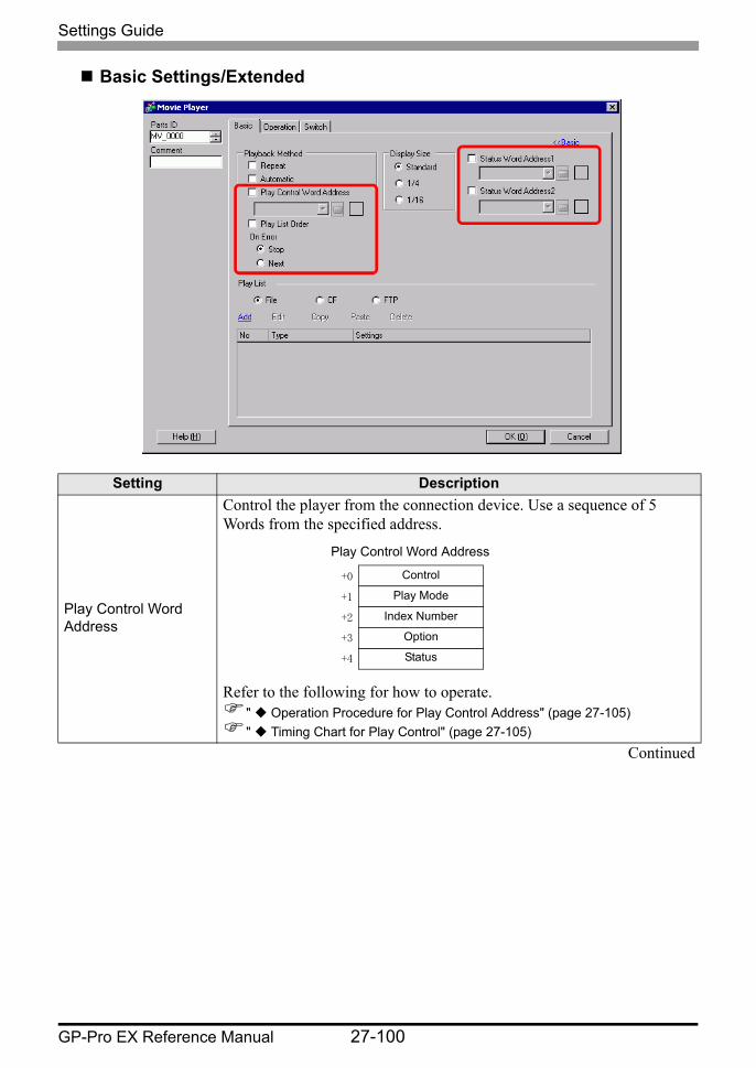
Settings Guide
GP-Pro EX Reference Manual 27-100
Basic Settings/Extended
Setting Description
Play Control Word Address
Control the player from the connection device. Use a sequence of 5 Words from the specified address.
Refer to the following for how to operate." Operation Procedure for Play Control Address" (page 27-105)" Timing Chart for Play Control" (page 27-105)
Continued
Play Control Word Address
Control
Play Mode
Index Number
Option
Status
+0
+1
+2
+3
+4
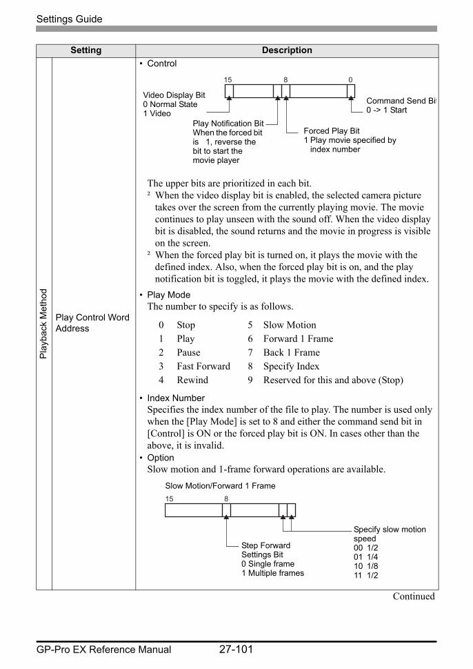
Settings Guide
GP-Pro EX Reference Manual 27-101
Pla
ybac
k M
etho
d
Play Control Word Address
• Control
The upper bits are prioritized in each bit.² When the video display bit is enabled, the selected camera picture
takes over the screen from the currently playing movie. The movie continues to play unseen with the sound off. When the video display bit is disabled, the sound returns and the movie in progress is visible on the screen.
² When the forced play bit is turned on, it plays the movie with the defined index. Also, when the forced play bit is on, and the play notification bit is toggled, it plays the movie with the defined index.
• Play ModeThe number to specify is as follows.
• Index NumberSpecifies the index number of the file to play. The number is used only when the [Play Mode] is set to 8 and either the command send bit in [Control] is ON or the forced play bit is ON. In cases other than the above, it is invalid.
• OptionSlow motion and 1-frame forward operations are available.
Continued
Setting Description
0815
Command Send Bit0 -> 1 Start
Forced Play Bit1 Play movie specified by
index number
Play Notification BitWhen the forced bit is 1, reverse the bit to start the movie player
Video Display Bit0 Normal State1 Video
0 Stop 5 Slow Motion1 Play 6 Forward 1 Frame2 Pause 7 Back 1 Frame3 Fast Forward 8 Specify Index4 Rewind 9 Reserved for this and above (Stop)
815
Specify slow motion speed00 1/201 1/410 1/811 1/2
Step Forward Settings Bit0 Single frame1 Multiple frames
Slow Motion/Forward 1 Frame

Settings Guide
GP-Pro EX Reference Manual 27-102
Pla
ybac
k M
etho
d
Play Control Word Address
• Status
(Error Code)
Reserved
Play List Order When the player reaches the end of the playlist, files will play as follows, depending on whether [Loop] is selected.[Repeat] selected: Plays movies from the top of the list.[Repeat] not selected: Stops playing movies.
On Error
Specifies how to handle the following types of errors when a movie file cannot play.• The CF Card is not inserted when CF play is selected• Unable to connect to FTP server when FTP play is selected• No file is found for CF play and FTP play• Cannot open the file for CF play and FTP play• The specified file is not in a format compatible for CF play or FTP play
Stop Stops the operation if the movie cannot be played.
Next If a movie cannot be played, plays the next movie file. In this case, no error status is stored in [Status Word Address 1].
Status Word Address 1
If you want to check the error information, play size, or information on the play position, specify a Word Address for storing the information. Use four Words from the specified address. For a 32-bit device, use the lower 16 bits only.
Continued
Setting Description
081115
CommandBit being accepted0 Stopped1 Outputting
Command Complete Bit0 -> 1 Command Completed
Error Status
0 Completed Successfully
1 The specified value for the play method is not within the setting range
2 Executing an instruction from the switch3 Saving a movie
4 to 15 Reserved
Status Word Address 1
Error Status
Play Size
Play Position X
Play Position Y
+0
+1
+2
+3
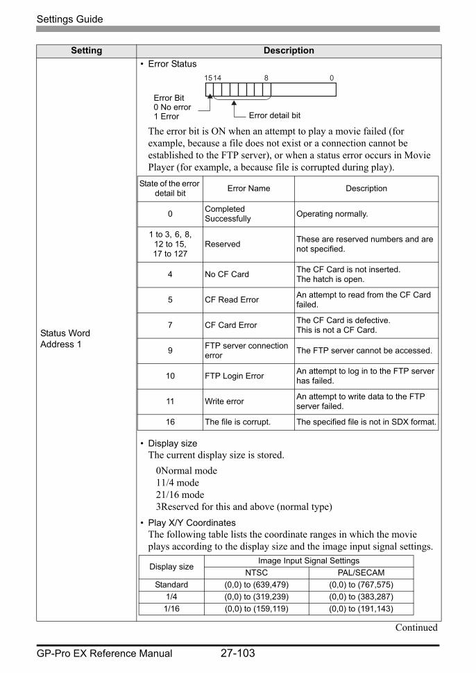
Settings Guide
GP-Pro EX Reference Manual 27-103
Status Word Address 1
• Error Status
The error bit is ON when an attempt to play a movie failed (for example, because a file does not exist or a connection cannot be established to the FTP server), or when a status error occurs in Movie Player (for example, a because file is corrupted during play).
• Display sizeThe current display size is stored.
0Normal mode11/4 mode21/16 mode3Reserved for this and above (normal type)
• Play X/Y CoordinatesThe following table lists the coordinate ranges in which the movie plays according to the display size and the image input signal settings.
Continued
Setting Description
081415
Error Bit0 No error1 Error Error detail bit
State of the error detail bit Error Name Description
0 Completed Successfully Operating normally.
1 to 3, 6, 8, 12 to 15,17 to 127
Reserved These are reserved numbers and are not specified.
4 No CF Card The CF Card is not inserted.The hatch is open.
5 CF Read Error An attempt to read from the CF Card failed.
7 CF Card Error The CF Card is defective.This is not a CF Card.
9 FTP server connection error The FTP server cannot be accessed.
10 FTP Login Error An attempt to log in to the FTP server has failed.
11 Write error An attempt to write data to the FTP server failed.
16 The file is corrupt. The specified file is not in SDX format.
Display sizeImage Input Signal Settings
NTSC PAL/SECAMStandard (0,0) to (639,479) (0,0) to (767,575)
1/4 (0,0) to (319,239) (0,0) to (383,287)1/16 (0,0) to (159,119) (0,0) to (191,143)

Settings Guide
GP-Pro EX Reference Manual 27-104
Status Word Address 2
Set to use the address for watching the movie playback state. Use a sequence of two words from the specified address. For a 32-bit device, use the lower 16 bits only.
• Play Monitor
• The operation mode for the Play Monitor is stored in the bottom eight bits.
• The play state bit turns ON during a video display using a play-list. It remains OFF during displays using a special switch.
• The play state bit indicates that the Play Monitor is actually in the play state. There are no repeat specifications, and even when the play switch is ON, if play is completed to the end, the state changes to state other than play state.
• The following lists the numbers to be specified for the Play Monitor operation mode.
0 Stop1 Play2 Pause3 Fast Forward4 Rewind5 Slow Motion00xFF Video DisplayNumbers other than those above are reserved.
• Slow Update RateWhen running in slow motion, stores the play speed.
Setting Description
Status Word Address 2
Play Monitor
Slow Update Rate+0
+1
078bit 15
Play state bit0 Not in the play state1 In the play state (excluding stop state).
Action Mode
815
Slow motion status bit00 1/201 1/410 1/8

Settings Guide
GP-Pro EX Reference Manual 27-105
Operation Procedure for Play Control AddressNormal Play
1 In the [Index Number] address, store the index number of the movie file you want to play.2 In the [Play Mode] address store the value 8, and in the [Control] address turn on the
command send bit (bit 0). The index number is set. (The movie being played will be stopped.)
3 Turns back the command send bit to off.4 In the [Play Mode] address store the value 1, and turn on the command send bit. This will
play the movie with the defined index number.
Play in Forced Play ModeRegardless of the current movie play status, forcibly plays the movie with the specified index number.
1 In the [Index Number] address, store the index number of the movie file you want to play.2 In the [Control] address, turn ON the forced play bit (bit 8). Play will begin.
Timing Chart for Play Control
• While the forced play bit is on, the command send bit will not turn on.• If the play notification bit (bit 9) is toggled while the forced play bit is on,
plays the movie with the current index number.• In forced play mode, to stop the movie from playing you need to turn off the
forced play bit. If neither [Loop] nor [Play List Order] is selected, movie playback stops at the end of the movie. If [Loop] is cleared and [Play List Order] is selected, movie playback stops at the end of the movie playlist.
Command send bit (PLC −> GP)
Command completeBit (GP −> PLC)
During the execution of a command (GP −> CF)Command being accepted Bit (GP -> PLC)

Settings Guide
GP-Pro EX Reference Manual 27-106
Operation
Setting DescriptionZoom Zoom display settings
Address Specify whether to use zoom display or not.
Zoom Word Address
Specify an address for zoom operations. Use a sequence of 3 Words from the specified address.For a 32-bit device, use only the bottom 16 bits.
" Timing Chart for Zoom Operation of the Movie Player" (page 27-109)
• Control
Continued
Control
Zoom specifications
Status
+0
+1
+2
Control the zoom function.
Specify the zoom size.
Display the error state, etc.
815
Zoom set bit0 Normal1 Zoom
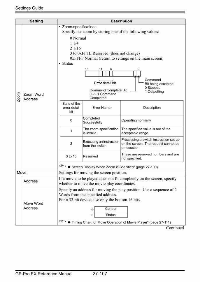
Settings Guide
GP-Pro EX Reference Manual 27-107
Zoom Zoom Word
Address
• Zoom specificationsSpecify the zoom by storing one of the following values:
0 Normal1 1/42 1/163 to 0xFFFE Reserved (does not change)0xFFFF Normal (return to settings on the main screen)
• Status
" Screen Display When Zoom is Specified" (page 27-109)Move Settings for moving the screen position.
Address If a movie to be played does not fit completely on the screen, specify whether to move the movie play coordinates.
Move Word Address
Specify an address for moving the play position. Use a sequence of 2 Words from the specified address.For a 32-bit device, use only the bottom 16 bits.
" Timing Chart for Move Operation of Movie Player" (page 27-111)Continued
Setting Description
081115
CommandBit being accepted0 Stopped1 OutputtingCommand Complete Bit
0 −> 1 Command Completed
Error detail bit
State of the error detail
bitError Name Description
0 Completed Successfully Operating normally.
1 The zoom specification is invalid.
The specified value is out of the acceptable range.
2 Executing an instruction from the switch
Processing a switch instruction set up on the screen. The request cannot be processed.
3 to 15 Reserved These are reserved numbers and are not specified.
Control
Status+0
+1
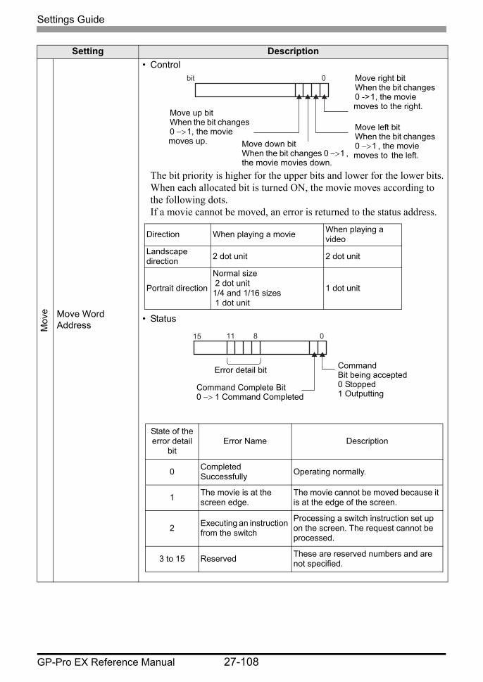
Settings Guide
GP-Pro EX Reference Manual 27-108
Mov
e Move Word Address
• Control
The bit priority is higher for the upper bits and lower for the lower bits.When each allocated bit is turned ON, the movie moves according to the following dots.If a movie cannot be moved, an error is returned to the status address.
• Status
Setting Description
0 bit
Move down bitWhen the bit changes 0 −> 1 , the movie movies down.
Move up bitWhen the bit changes 0 −> 1, the movie moves up.
Move right bitWhen the bit changes 0 -> 1, the movie moves to the right.
Move left bitWhen the bit changes 0 −> 1 , the movie moves to the left.
Direction When playing a movie When playing a video
Landscape direction 2 dot unit 2 dot unit
Portrait direction
Normal size 2 dot unit1/4 and 1/16 sizes 1 dot unit
1 dot unit
081115
CommandBit being accepted0 Stopped1 Outputting
Command Complete Bit0 −> 1 Command Completed
Error detail bit
State of the error detail
bitError Name Description
0 Completed Successfully Operating normally.
1 The movie is at the screen edge.
The movie cannot be moved because it is at the edge of the screen.
2 Executing an instruction from the switch
Processing a switch instruction set up on the screen. The request cannot be processed.
3 to 15 Reserved These are reserved numbers and are not specified.
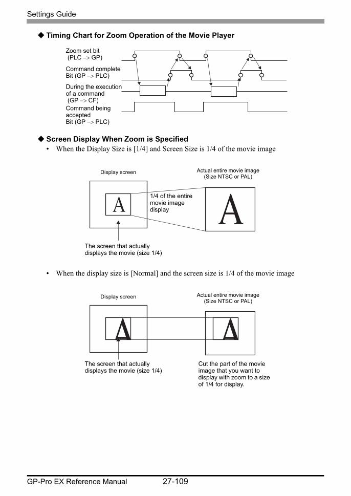
Settings Guide
GP-Pro EX Reference Manual 27-109
Timing Chart for Zoom Operation of the Movie Player
Screen Display When Zoom is Specified• When the Display Size is [1/4] and Screen Size is 1/4 of the movie image
• When the display size is [Normal] and the screen size is 1/4 of the movie image
Zoom set bit (PLC −> GP)
Command completeBit (GP −> PLC)
During the execution of a command (GP −> CF)Command being acceptedBit (GP −> PLC)
The screen that actually displays the movie (size 1/4)
Display screen
1/4 of the entire movie image display
Actual entire movie image(Size NTSC or PAL)
The screen that actually displays the movie (size 1/4)
Display screen Actual entire movie image(Size NTSC or PAL)
Cut the part of the movie image that you want to display with zoom to a size of 1/4 for display.
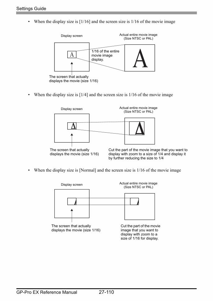
Settings Guide
GP-Pro EX Reference Manual 27-110
• When the display size is [1/16] and the screen size is 1/16 of the movie image
• When the display size is [1/4] and the screen size is 1/16 of the movie image
• When the display size is [Normal] and the screen size is 1/16 of the movie image
The screen that actually displays the movie (size 1/16)
Display screen
1/16 of the entire movie image display.
Actual entire movie image(Size NTSC or PAL)
The screen that actually displays the movie (size 1/16)
Display screen Actual entire movie image(Size NTSC or PAL)
Cut the part of the movie image that you want to display with zoom to a size of 1/4 and display it by further reducing the size to 1/4
The screen that actually displays the movie (size 1/16)
Display screen Actual entire movie image(Size NTSC or PAL)
Cut the part of the movie image that you want to display with zoom to a size of 1/16 for display.

Settings Guide
GP-Pro EX Reference Manual 27-111
• If a movie image is zoomed and the size is smaller than the display size, the display size automatically changes to the movie image size.
Timing Chart for Move Operation of Movie Player
Display screen
Actual loaded image
Display screen
Actual loaded image
Move bit (PLC −> GP)
Command completeBit (GP −> PLC)
During the execution of a command (GP −> CF)
Command being acceptedBit (GP −> PLC)
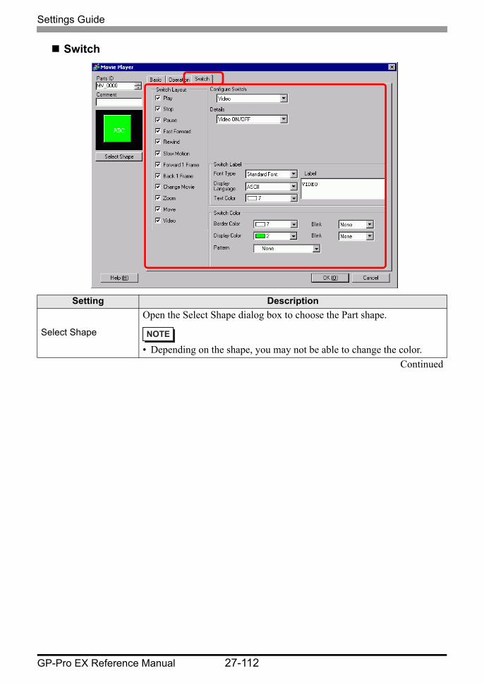
Settings Guide
GP-Pro EX Reference Manual 27-112
Switch
Setting Description
Select Shape
Open the Select Shape dialog box to choose the Part shape.
• Depending on the shape, you may not be able to change the color.Continued
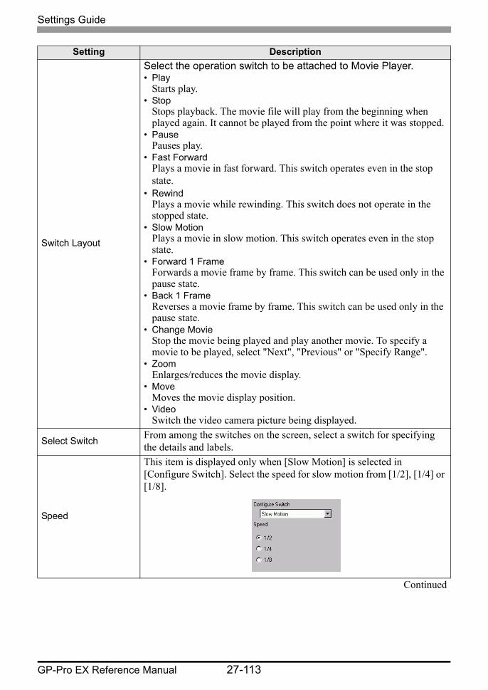
Settings Guide
GP-Pro EX Reference Manual 27-113
Switch Layout
Select the operation switch to be attached to Movie Player.• Play
Starts play.• Stop
Stops playback. The movie file will play from the beginning when played again. It cannot be played from the point where it was stopped.
• PausePauses play.
• Fast ForwardPlays a movie in fast forward. This switch operates even in the stop state.
• RewindPlays a movie while rewinding. This switch does not operate in the stopped state.
• Slow MotionPlays a movie in slow motion. This switch operates even in the stop state.
• Forward 1 FrameForwards a movie frame by frame. This switch can be used only in the pause state.
• Back 1 FrameReverses a movie frame by frame. This switch can be used only in the pause state.
• Change MovieStop the movie being played and play another movie. To specify a movie to be played, select "Next", "Previous" or "Specify Range".
• ZoomEnlarges/reduces the movie display.
• MoveMoves the movie display position.
• VideoSwitch the video camera picture being displayed.
Select Switch From among the switches on the screen, select a switch for specifying the details and labels.
Speed
This item is displayed only when [Slow Motion] is selected in [Configure Switch]. Select the speed for slow motion from [1/2], [1/4] or [1/8].
Continued
Setting Description

Settings Guide
GP-Pro EX Reference Manual 27-114
Step Forward Settings
This item is displayed only when [Forward 1 Frame] is selected in [Configure Switch]. Select the frame width.Multiple Frames: Forward a movie by "I" frames.Single Frame: Forward a movie by one frame.
ForwardThis item is displayed only when [Forward 1 Frame] is selected in [Configure Switch]. While pressing the switch, specify whether to continuously forward a movie frame by frame.
Backward
This item is displayed only when [Back 1 Frame] is selected in [Configure Switch]. While pressing the switch, specify whether to continuously reverse a movie frame by frame.
Detail Action
This item is displayed only when [Change Movie] is selected in [Configure Switch]. Select the operation for switching movies.NextPreviousPlay List
LoopThis item is displayed only when [Change Movie] is selected in [Configure Switch], and [Next] or [Previous] is selected in [Details]. Specify whether to perform a loop operation.
Index Number
This item is displayed only when [Change Movie] is selected in [Configure Switch], and [Play List] is specified in [Details]. Specify the Index Number of the movie file to be played. The setting range is from 0 to 99.
Action ModeThis item is displayed only when [Zoom] is selected in [Configure Switch]. Select how to specify the display size from either [Direct] or [Indirect].
Continued
Setting Description
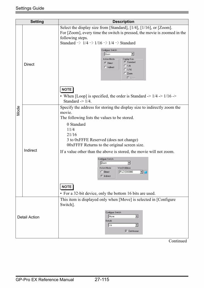
Settings Guide
GP-Pro EX Reference Manual 27-115
Mod
e
Direct
Select the display size from [Standard], [1/4], [1/16], or [Zoom].For [Zoom], every time the switch is pressed, the movie is zoomed in the following steps.Standard -> 1/4 -> 1/16 -> 1/4 -> Standard
• When [Loop] is specified, the order is Standard -> 1/4 -> 1/16 -> Standard -> 1/4.
Indirect
Specify the address for storing the display size to indirectly zoom the movie.The following lists the values to be stored.
0 Standard11/421/163 to 0xFFFE Reserved (does not change)00xFFFF Returns to the original screen size.
If a value other than the above is stored, the movie will not zoom.
• For a 32-bit device, only the bottom 16 bits are used.
Detail Action
This item is displayed only when [Move] is selected in [Configure Switch].
Continued
Setting Description
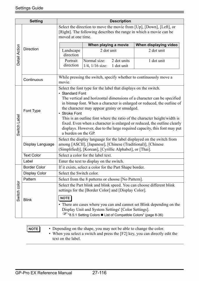
Settings Guide
GP-Pro EX Reference Manual 27-116
Det
ail A
ctio
n
Direction
Select the direction to move the movie from [Up], [Down], [Left], or [Right]. The following describes the range in which a movie can be moved at one time.
Continuous While pressing the switch, specify whether to continuously move a movie.
Sw
itch
Labe
l
Font Type
Select the font type for the label that displays on the switch.• Standard Font
The vertical and horizontal dimensions of a character can be specified in bitmap font. When a character is enlarged or reduced, the outline of the character may appear grainy or smudged.
• Stroke FontThis is an outline font where the ratio of the character height/width is fixed. Even when a character is enlarged or reduced, the outline clearly displays. However, due to the large required capacity, this font may put a burden on the GP.
Display LanguageSelect the display language for the label displayed on the switch from among [ASCII], [Japanese], [Chinese (Traditional)], [Chinese (Simplified)], [Korean], [Cyrillic Alphabet], or [Thai].
Text Color Select a color for the label text.Label Enter the text to display on the switch.
Sw
itch
colo
r
Border Color If it exists, select a color for the Part Shape border.Display Color Select the Switch color.Pattern Select from the 8 patterns or choose [No Pattern].
Blink
Select the Part blink and blink speed. You can choose different blink settings for the [Border Color] and [Display Color].
• There are cases where you can and cannot set Blink depending on the Display Unit and System Settings' [Color Settings].
"8.5.1 Setting Colors List of Compatible Colors" (page 8-36)
• Depending on the shape, you may not be able to change the color.• When you select a switch and press the [F2] key, you can directly edit the
text on the label.
Setting Description
When playing a movie When displaying videoLandscape direction
2 dot unit 2 dot unit
Portrait direction
Normal size: 2 dot units1/4, 1/16 size: 1 dot unit
1 dot unit
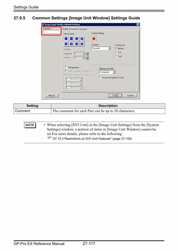
Settings Guide
GP-Pro EX Reference Manual 27-117
27.9.5 Common Settings [Image Unit Window] Settings Guide
Setting DescriptionComment The comment for each Part can be up to 20 characters.
• When selecting [DVI Unit] in the [Image Unit Settings] from the [System Settings] window, a portion of items in [Image Unit Window] cannot be set.For more details, please refer to the following.
"27.10.3 Restrictions on DVI Unit Features" (page 27-155)
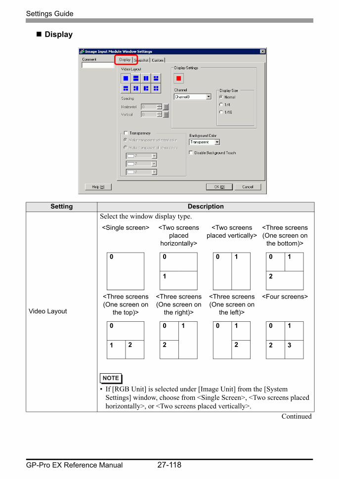
Settings Guide
GP-Pro EX Reference Manual 27-118
Display
Setting Description
Video Layout
Select the window display type.
• If [RGB Unit] is selected under [Image Unit] from the [System Settings] window, choose from <Single Screen>, <Two screens placed horizontally>, or <Two screens placed vertically>.
Continued
<Single screen> <Two screens placed
horizontally>
<Two screens placed vertically>
<Three screens (One screen on
the bottom)>
<Three screens (One screen on
the top)>
<Three screens (One screen on
the right)>
<Three screens (One screen on
the left)>
<Four screens>
0 0
1
0 1 0
2
1
0
1 2
0
2
1 0 1
2
0
2
1
3

Settings Guide
GP-Pro EX Reference Manual 27-119
Spacing
Specify this setting when two or more screens are displayed simultaneously.• Horizontal: Specify the number of pixels between windows side by side.• Vertical: Specify the number of pixels between windows on top of each
other.Each window size has different setup ranges.
Display Specify the display settings for each screen according to the selected window type.
Channel Select a Channel Number on which the display settings are to be specified.
Channels 0 - 3
Displays the video camera image input to the specified channel.When using a VM Unit (3000):
• AGP-3510 and AGP-3560 work in the same way as AGP-36∗0T.
Display size
RGB(IN) 0, RGB(IN) 1, DVI/RGB(IN)
Displays an image from a device connected via a DVI/RGB interface.
• [DVI/RGB(IN)] is displayed when [DVI Unit] is selected in [Image Input Module] under [System Settings].
• [RGB(IN) 0] and [RGB(IN) 1] are displayed when [RGB Unit] is selected in [Image Input Module] under [System Settings].
Emulate Touch
Sends the screen touch information to an external device connected via serial communication.The following lists the maximum effective area of the X/Y coordinates for the entire screen display.
For AGP-35∗OT, X coordinate: 0 to 639; Y coordinate: 0 to 479For AGP-36∗0T X coordinate: 0 to 799 Y coordinate: 0 to 599For AGP-37∗OT, X coordinate: 0 to 1023; Y coordinate: 0 to 767
Continued
Setting Description
DisplaySize
NTSC PALAGP-35*0T AGP-36*0T AGP-37*0T AGP-35*0T AGP-35*0T AGP-37*0T
Normal 640 x 480 Dot
640 x 480Dot
640 x 480Dot
640 x 480Dot*1
*1 If setting the video input to PAL while using AGP-35∗0T, part of the image will normally not be displayed.
768 x 576Dot
768 x 576Dot
1/4 320 x 240Dot
320 x 240Dot
320 x 240Dot
384 x 288Dot
384 x 288Dot
384 x 288Dot
1/16 160 x 120Dot
160 x 120Dot
160 x 120Dot
192 x 144Dot
192 x 144Dot
192 x 144Dot
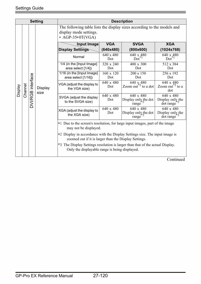
Settings Guide
GP-Pro EX Reference Manual 27-120
Dis
play
Cha
nnel
DV
I/RG
B in
terfa
ce
Display size
The following table lists the display sizes according to the models and display mode settings.• AGP-35∗0T(VGA)
Continued
Setting Description
Input ImageDisplay Settings
VGA(640x480)
SVGA(800x600)
XGA(1024x768)
Normal 640 x 480Dot
640 x 480Dot*1
*1 Due to the screen's resolution, for large input images, part of the image may not be displayed.
640 x 480Dot*1
1/4 (in the [Input Image] area select [1/4])
320 x 240Dot
400 x 300Dot
512 x 384Dot
1/16 (in the [Input Image] area select [1/16])
160 x 120Dot
200 x 150Dot
256 x 192Dot
VGA (adjust the display to the VGA size)
640 x 480Dot
640 x 480Zoom out*2 to a dot
*2 Display in accordance with the Display Settings size. The input image is zoomed out if it is larger than the Display Settings.
640 x 480Zoom out*2 to a
dot
SVGA (adjust the display to the SVGA size)
640 x 480Dot
640 x 480Display only the dot
range*3
*3 The Display Settings resolution is larger than that of the actual Display. Only the displayable range is being displayed.
640 x 480Display only the
dot range*3
XGA (adjust the display to the XGA size)
640 x 480Dot
640 x 480Display only the dot
range*3
640 x 480Display only the
dot range*3
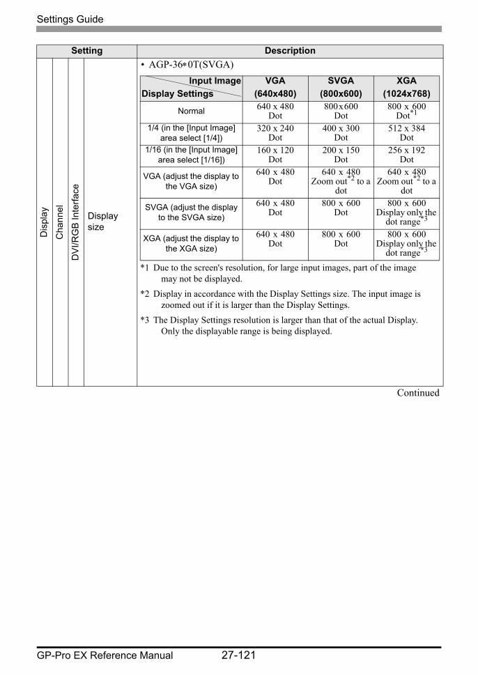
Settings Guide
GP-Pro EX Reference Manual 27-121
Dis
play
Cha
nnel
DV
I/RG
B In
terfa
ce
Display size
• AGP-36∗0T(SVGA)
Continued
Setting Description
Input ImageDisplay Settings
VGA(640x480)
SVGA(800x600)
XGA(1024x768)
Normal 640 x 480Dot
800 x 600Dot
800 x 600Dot*1
*1 Due to the screen's resolution, for large input images, part of the image may not be displayed.
1/4 (in the [Input Image] area select [1/4])
320 x 240Dot
400 x 300Dot
512 x 384Dot
1/16 (in the [Input Image] area select [1/16])
160 x 120Dot
200 x 150Dot
256 x 192Dot
VGA (adjust the display to the VGA size)
640 x 480Dot
640 x 480Zoom out*2 to a
dot
*2 Display in accordance with the Display Settings size. The input image is zoomed out if it is larger than the Display Settings.
640 x 480Zoom out*2 to a
dot
SVGA (adjust the display to the SVGA size)
640 x 480Dot
800 x 600Dot
800 x 600Display only the
dot range*3
*3 The Display Settings resolution is larger than that of the actual Display. Only the displayable range is being displayed.
XGA (adjust the display to the XGA size)
640 x 480Dot
800 x 600Dot
800 x 600Display only the
dot range*3

Settings Guide
GP-Pro EX Reference Manual 27-122
Dis
play
Cha
nnel
DV
I/RG
B In
terfa
ce
Display size
• AGP-37∗0T(XGA)
• AGP-3510 and AGP-3560 work in the same way as AGP-36∗0T.
JPG
Display JPEG files on the CF card. You can specify multiple settings for displaying JPEG images on the same screen and select [JPG File Number] redundantly.
• Even if an attempt is made to turn OFF the video screen while a JPEG image is displayed, the screen will not turn OFF until the display processing has completed.
• In addition to a CF card, you can display the files in a USB storage device.
• In the System Settings, select [Display Unit] and click the [Mode] tab. In the [Screen Capture Settings], select the [Capture Action] check box. When you select the files to be saved in a USB storage device, the files in the USB storage device will be displayed. When selecting FTP server, the CF card will be selected.
JPG file number
Specify the JPEG file number for the file you want to display from 0 to 65535.
Display size
Select the screen display size from [Normal], [1/4], [1/16] and [1/64].The percentage of reduction is based on the display screen size, not the display mode.
Continued
Setting Description
Input ImageDisplay Settings
VGA(640x480)
SVGA(800x600)
XGA(1024x768)
Normal 640 x 480Dot
800 x 600Dot
1024 x 768Dot
1/4 (in the [Input Image] area select [1/4])
320 x 240Dot
400 x 300Dot
512 x 384Dot
1/16 (in the [Input Image] area select [1/16])
160 x 120Dot
200 x 150Dot
256 x 192Dot
VGA (adjust the display to the VGA size)
640 x 480Dot
640 x 480Zoom out*1 to a
dot
*1 Display in accordance with the Display Settings size. The input image is zoomed out if it is larger than the Display Settings.
640 x 480Zoom out*1 to a
dotSVGA (adjust the display
to the SVGA size)640 x 480
Dot800 x 600
Dot800 x 600
DotXGA (adjust the display to
the XGA size)640 x 480
Dot800 x 600
Dot1024 x 768
Dot
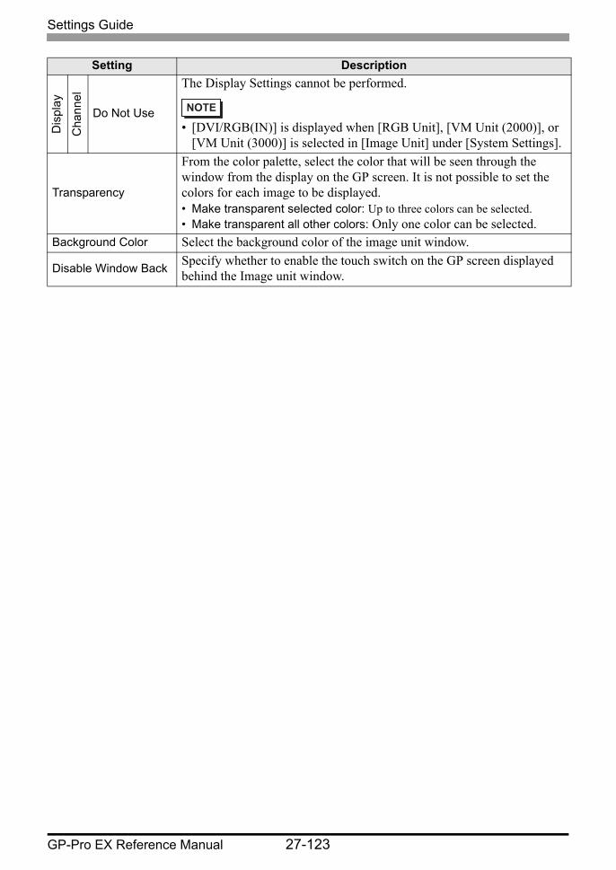
Settings Guide
GP-Pro EX Reference Manual 27-123
Dis
play
Cha
nnel
Do Not Use
The Display Settings cannot be performed.
• [DVI/RGB(IN)] is displayed when [RGB Unit], [VM Unit (2000)], or [VM Unit (3000)] is selected in [Image Unit] under [System Settings].
Transparency
From the color palette, select the color that will be seen through the window from the display on the GP screen. It is not possible to set the colors for each image to be displayed.• Make transparent selected color: Up to three colors can be selected.• Make transparent all other colors: Only one color can be selected.
Background Color Select the background color of the image unit window.
Disable Window Back Specify whether to enable the touch switch on the GP screen displayed behind the Image unit window.
Setting Description

Settings Guide
GP-Pro EX Reference Manual 27-124
Snapshot
Setting Description
Video snapshot
Captures a shot of the video from a single channel and specifies whether to save it to the CF card as a JPG file.Using Capture Output, the picture from the channel specified in the [Image Unit Window Settings] is output in JPEG format. The size of the output image is 640 x 480 pixels for NTSC and 768 x 576 for PAL signals.
• To use the video capture feature, in the System Settings window's [Image Input Module Settings] page, [enable] the [Video Control Start Address]. In the defined video address, turn ON bit 4 to initiate the video capture.
Captured Channel Select the channel to capture.
JPG
file
num
ber
Direct
Set a number to be the JPEG file name. The setting range is from 0 to 65535.The saved file name is "CPXXXXX.JPG" (XXXXX is the specified value). The file will be stored in the "CAPTURE" folder the CF card.
• The file is always saved using the file name defined here. If a file with the same name already exists in the CF card, that file will be overwritten.
• In the system settings window, select [Display Unit] and click the [Mode] tab. From [Screen Capture Settings], select the [Capture Action] check box. When you select the files saved in the FTP server, this setting is disabled.In this case, the file number become a time stamp (saves the starting year, month, day, hour, minute, second).
Continued
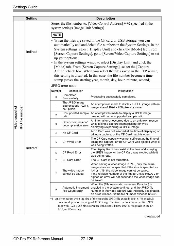
Settings Guide
GP-Pro EX Reference Manual 27-125
Vide
o sn
apsh
ot
JPG
file
num
ber
Indirect
Stores the file number to: [Video Control Address] + +2 specified in the system settings [Image Unit Settings].
• When the files are saved in the CF card or USB storage, you can automatically add and delete file numbers in the System Settings. In the System settings, select [Display Unit] and click the [Mode] tab. From [Screen Capture Settings], go to [Screen/Video Capture Settings] to set up your options.
• In the system settings window, select [Display Unit] and click the [Mode] tab. From [Screen Capture Settings], select the [Capture Action] check box. When you select the files saved in the FTP server, this setting is disabled. In this case, the file number become a time stamp (saves the starting year, month, day, hour, minute, second).
Indirect
JPEG error code
Continued
Setting Description
Number Description Introduction
0Completed Successfully Processing successfully completed.
1
The JPEG image size exceeds 1024 x 768 pixels.
An attempt was made to display a JPEG image with an image size of 1024 x 768 pixels or more.*1
*1 An error occurs when the size of the expanded JPEG file exceeds 1024 x 768 pixels.It does not depend on the original JPEG image file.An error does not occur for JPEG files with 1024 x 768 pixels or more if the size is below 1024 x 768 pixels in the 1/4, 1/16, or 1/64 setting.
2Unsupported sample ratio
An attempt was made to display a JPEG image created with an unsupported sample ratio.
3Other compression/decompression error
An internal error occurred due to an unknown reason while taking a capture (compressing) or while displaying (expanding) a JPEG image.
4 No CF Card A CF Card was not inserted at the time of displaying or taking a capture, or the CF Card hatch is open.
5 CF Write ErrorThe CF Card capacity was not sufficient at the time of taking the capture, or the CF Card was ejected while it was being written.
6 CF Read ErrorThe display file did not exist at the time of displaying the JPEG image, or the CF Card was ejected while it was being read.
7 CF Card Error The CF Card is not formatted.
8The video image cannot be saved.
When saving a video image in PAL, only the actual image size can be specified.If the size is specified as 1/4 or 1/16, the video image cannot be saved. If the revision Number of the Image Unit is Rev.A-2 or higher, an error will not occur and the video image can be saved.
9Automatic Increment File Count Error
When the [File Automatic Increment Function] is enabled in the system settings, and the JPEG file Number of the video capture was indirectly designated, an error will occur if the file Number exceeds 65535.
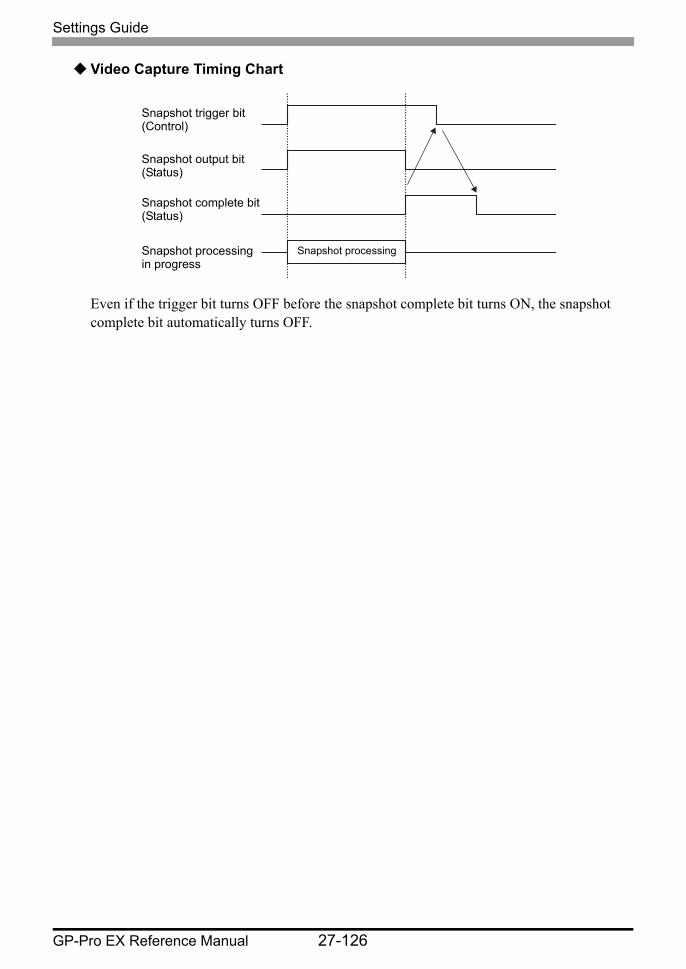
Settings Guide
GP-Pro EX Reference Manual 27-126
Video Capture Timing Chart
Even if the trigger bit turns OFF before the snapshot complete bit turns ON, the snapshot complete bit automatically turns OFF.
Snapshot trigger bit(Control)
Snapshot output bit(Status)
Snapshot complete bit(Status)
Snapshot processing in progress
Snapshot processing
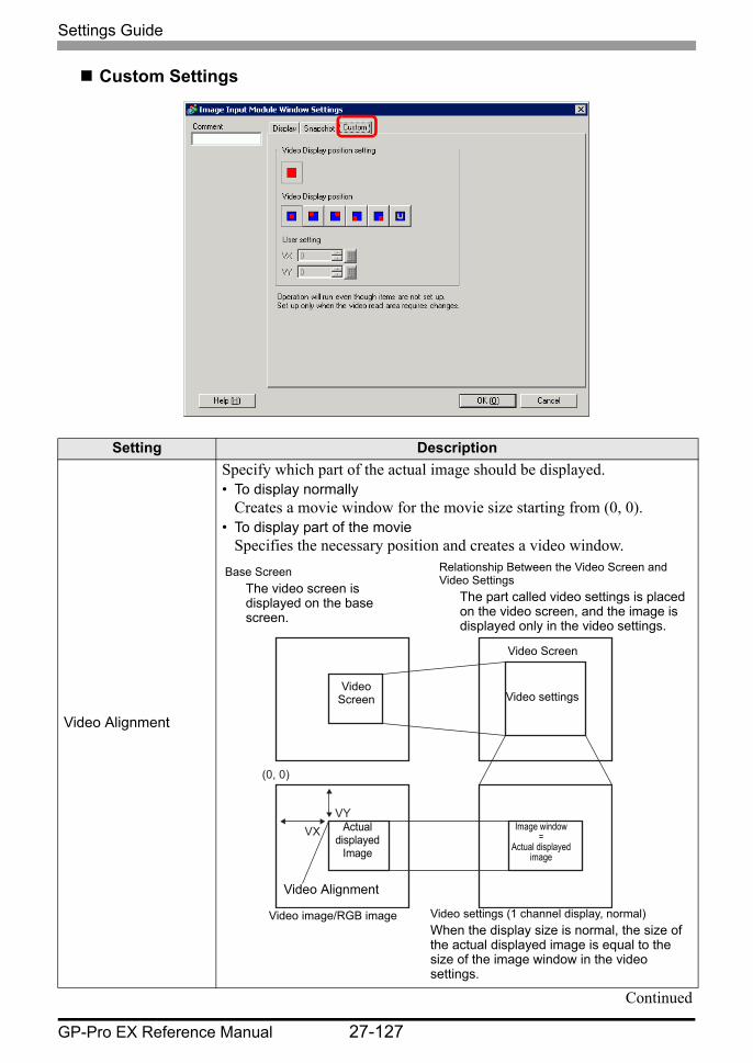
Settings Guide
GP-Pro EX Reference Manual 27-127
Custom Settings
Setting Description
Video Alignment
Specify which part of the actual image should be displayed.• To display normally
Creates a movie window for the movie size starting from (0, 0).• To display part of the movie
Specifies the necessary position and creates a video window.
Continued
VY VX
(0, 0)
Base ScreenThe video screen is displayed on the base screen.
Relationship Between the Video Screen and Video Settings
The part called video settings is placed on the video screen, and the image is displayed only in the video settings.
Video Screen Video settings
Image window=
Actual displayed image
Video Alignment
Actual displayed
Image
Video settings (1 channel display, normal)When the display size is normal, the size of the actual displayed image is equal to the size of the image window in the video settings.
Video Screen
Video image/RGB image

Settings Guide
GP-Pro EX Reference Manual 27-128
Video Alignment
Video Display position
For each display screen, select the video display position from , , , , , and .
If is selected, the X/Y coordinates can be specified.• VX: Specify from 0 to 1023.• VY: Specify from 0 to 767.
Setting Description
VY VX
Video Settings (channel display, 1/4 (reduced display))
When the display size is reduced (1/4), the size of the actual displayed image is four times as large as the size of the image window in the video settings (for 1/16, the size is 16 times larger).
Video Alignment
Video image/RGB image
Image window x 4=
Actual displayed image
Actual displayed
Image

Settings Guide
GP-Pro EX Reference Manual 27-129
27.9.6 [Image Unit Settings] Settings Guide
This section describes the basic settings of the optional Video Module Unit or DVI Unit.
Display Settings/Basic
Setting Description
Image Unit
Choose the unit to set up from [VM Unit (2000)], [VM Unit (3000)], [DVI Unit], or [RGB Unit].
• When [DVI Unit] is selected, some features may be disabled."27.10.3 Restrictions on DVI Unit Features" (page 27-155)
Video Control Start Address Specifies whether or not to use the control address.
Disable Does not use the control address.
Enable
Set the GP internal device address for controlling the display of the Image Unit Window.Use a sequence of 42 Words from the specified address.The settings range for the video module unit is between LS20 - 1989 and 2096 - 8957, and for the DVI unit is between LS20 - 2026 and 2096 - 8894.
" Video Control Area" (page 27-130)
• If an address is specified outside of the settings range, the VM function will not run.
Video SignalSelect the image input signal.• NTSC: 640 x 480 pixels• PAL: 768 x 576 pixels
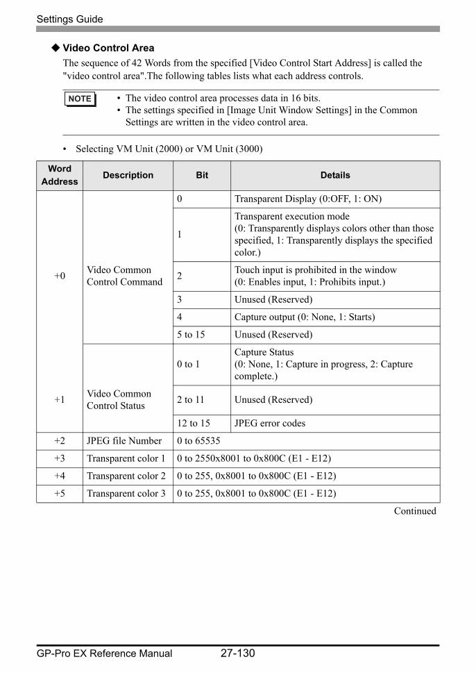
Settings Guide
GP-Pro EX Reference Manual 27-130
Video Control AreaThe sequence of 42 Words from the specified [Video Control Start Address] is called the "video control area".The following tables lists what each address controls.
• Selecting VM Unit (2000) or VM Unit (3000)
• The video control area processes data in 16 bits.• The settings specified in [Image Unit Window Settings] in the Common
Settings are written in the video control area.
Word Address
Description Bit Details
0 Transparent Display (0:OFF, 1: ON)
1
Transparent execution mode (0: Transparently displays colors other than those specified, 1: Transparently displays the specified color.)
+0 Video Common Control Command 2 Touch input is prohibited in the window
(0: Enables input, 1: Prohibits input.)
3 Unused (Reserved)
4 Capture output (0: None, 1: Starts)
5 to 15 Unused (Reserved)
0 to 1Capture Status (0: None, 1: Capture in progress, 2: Capture complete.)
+1 Video Common Control Status 2 to 11 Unused (Reserved)
12 to 15 JPEG error codes
+2 JPEG file Number 0 to 65535
+3 Transparent color 1 0 to 2550x8001 to 0x800C (E1 - E12)
+4 Transparent color 2 0 to 255, 0x8001 to 0x800C (E1 - E12)
+5 Transparent color 3 0 to 255, 0x8001 to 0x800C (E1 - E12)
Continued
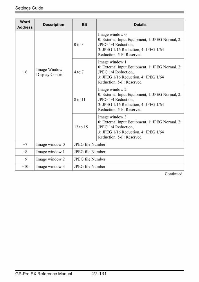
Settings Guide
GP-Pro EX Reference Manual 27-131
0 to 3
Image window 00: External Input Equipment, 1: JPEG Normal, 2: JPEG 1/4 Reduction, 3: JPEG 1/16 Reduction, 4: JPEG 1/64 Reduction, 5-F: Reserved
+6 Image Window Display Control 4 to 7
Image window 10: External Input Equipment, 1: JPEG Normal, 2: JPEG 1/4 Reduction, 3: JPEG 1/16 Reduction, 4: JPEG 1/64 Reduction, 5-F: Reserved
8 to 11
Image window 20: External Input Equipment, 1: JPEG Normal, 2: JPEG 1/4 Reduction, 3: JPEG 1/16 Reduction, 4: JPEG 1/64 Reduction, 5-F: Reserved
12 to 15
Image window 30: External Input Equipment, 1: JPEG Normal, 2: JPEG 1/4 Reduction, 3: JPEG 1/16 Reduction, 4: JPEG 1/64 Reduction, 5-F: Reserved
+7 Image window 0 JPEG file Number
+8 Image window 1 JPEG file Number
+9 Image window 2 JPEG file Number
+10 Image window 3 JPEG file Number
Continued
Word Address
Description Bit Details
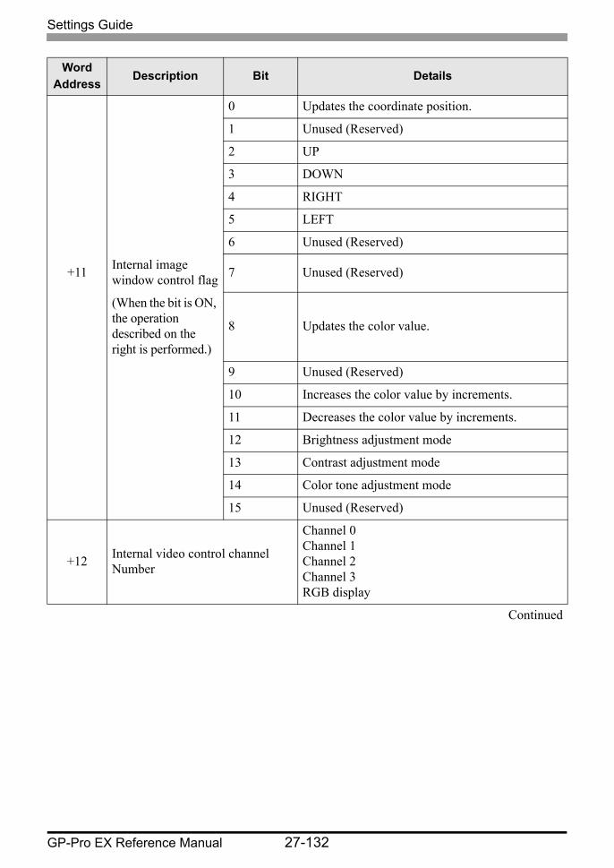
Settings Guide
GP-Pro EX Reference Manual 27-132
0 Updates the coordinate position.
1 Unused (Reserved)
2 UP
3 DOWN
4 RIGHT
5 LEFT
6 Unused (Reserved)
+11 Internal image window control flag 7 Unused (Reserved)
(When the bit is ON, the operation described on the right is performed.)
8 Updates the color value.
9 Unused (Reserved)
10 Increases the color value by increments.
11 Decreases the color value by increments.
12 Brightness adjustment mode
13 Contrast adjustment mode
14 Color tone adjustment mode
15 Unused (Reserved)
+12 Internal video control channel Number
Channel 0Channel 1Channel 2Channel 3RGB display
Continued
Word Address
Description Bit Details
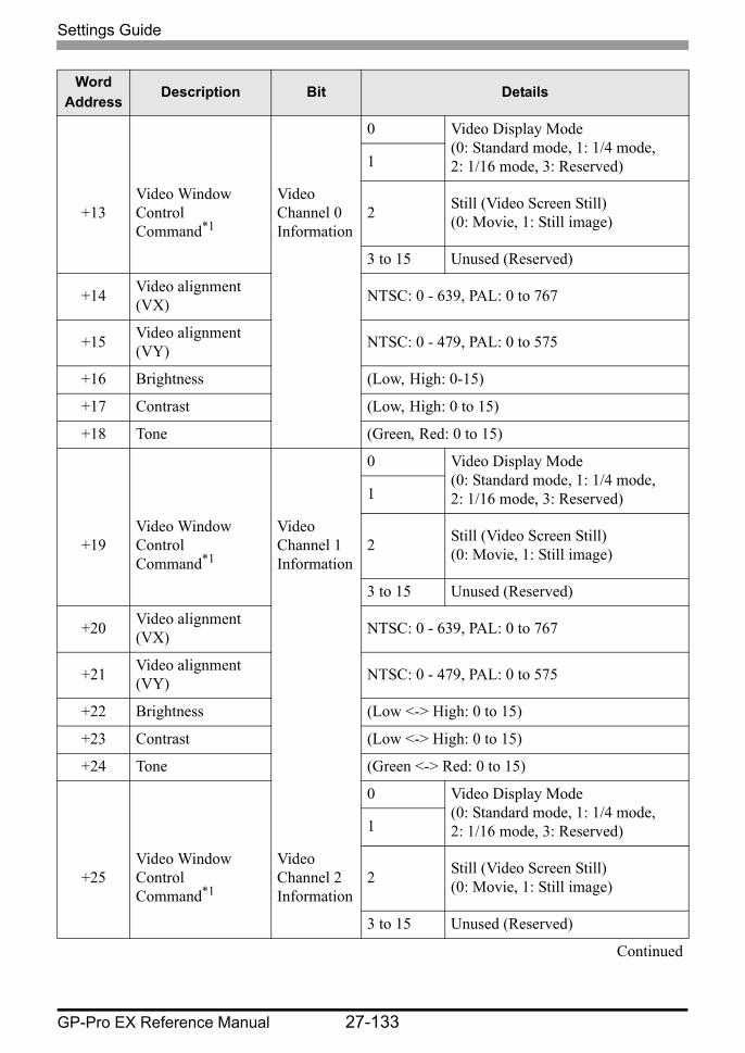
Settings Guide
GP-Pro EX Reference Manual 27-133
0 Video Display Mode (0: Standard mode, 1: 1/4 mode, 2: 1/16 mode, 3: Reserved)1
+13Video Window Control Command*1
Video Channel 0 Information
2 Still (Video Screen Still) (0: Movie, 1: Still image)
3 to 15 Unused (Reserved)
+14 Video alignment (VX) NTSC: 0 - 639, PAL: 0 to 767
+15 Video alignment (VY) NTSC: 0 - 479, PAL: 0 to 575
+16 Brightness (Low, High: 0-15)
+17 Contrast (Low, High: 0 to 15)
+18 Tone (Green, Red: 0 to 15)
0 Video Display Mode (0: Standard mode, 1: 1/4 mode, 2: 1/16 mode, 3: Reserved)1
+19Video Window Control Command*1
Video Channel 1 Information
2 Still (Video Screen Still) (0: Movie, 1: Still image)
3 to 15 Unused (Reserved)
+20 Video alignment (VX) NTSC: 0 - 639, PAL: 0 to 767
+21 Video alignment (VY) NTSC: 0 - 479, PAL: 0 to 575
+22 Brightness (Low <-> High: 0 to 15)
+23 Contrast (Low <-> High: 0 to 15)
+24 Tone (Green <-> Red: 0 to 15)
0 Video Display Mode (0: Standard mode, 1: 1/4 mode, 2: 1/16 mode, 3: Reserved)1
+25Video Window Control Command*1
Video Channel 2 Information
2 Still (Video Screen Still) (0: Movie, 1: Still image)
3 to 15 Unused (Reserved)
Continued
Word Address
Description Bit Details
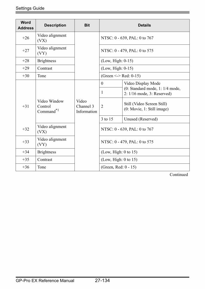
Settings Guide
GP-Pro EX Reference Manual 27-134
+26 Video alignment (VX) NTSC: 0 - 639, PAL: 0 to 767
+27 Video alignment (VY) NTSC: 0 - 479, PAL: 0 to 575
+28 Brightness (Low, High: 0-15)
+29 Contrast (Low, High: 0-15)
+30 Tone (Green <-> Red: 0-15)
0 Video Display Mode (0: Standard mode, 1: 1/4 mode, 2: 1/16 mode, 3: Reserved)1
+31Video Window Control Command*1
Video Channel 3 Information
2 Still (Video Screen Still) (0: Movie, 1: Still image)
3 to 15 Unused (Reserved)
+32 Video alignment (VX) NTSC: 0 - 639, PAL: 0 to 767
+33 Video alignment (VY) NTSC: 0 - 479, PAL: 0 to 575
+34 Brightness (Low, High: 0 to 15)
+35 Contrast (Low, High: 0 to 15)
+36 Tone (Green, Red: 0 - 15)
Continued
Word Address
Description Bit Details
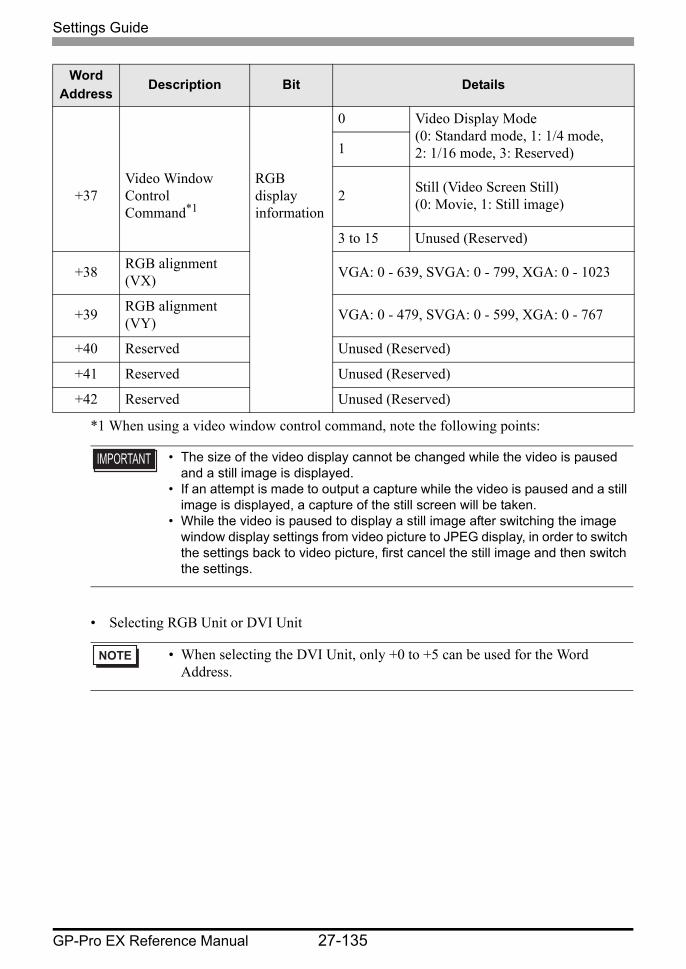
Settings Guide
GP-Pro EX Reference Manual 27-135
*1 When using a video window control command, note the following points:
• Selecting RGB Unit or DVI Unit
0 Video Display Mode (0: Standard mode, 1: 1/4 mode, 2: 1/16 mode, 3: Reserved)1
+37Video Window Control Command*1
RGB display information
2 Still (Video Screen Still) (0: Movie, 1: Still image)
3 to 15 Unused (Reserved)
+38 RGB alignment (VX) VGA: 0 - 639, SVGA: 0 - 799, XGA: 0 - 1023
+39 RGB alignment (VY) VGA: 0 - 479, SVGA: 0 - 599, XGA: 0 - 767
+40 Reserved Unused (Reserved)
+41 Reserved Unused (Reserved)
+42 Reserved Unused (Reserved)
• The size of the video display cannot be changed while the video is paused and a still image is displayed.
• If an attempt is made to output a capture while the video is paused and a still image is displayed, a capture of the still screen will be taken.
• While the video is paused to display a still image after switching the image window display settings from video picture to JPEG display, in order to switch the settings back to video picture, first cancel the still image and then switch the settings.
• When selecting the DVI Unit, only +0 to +5 can be used for the Word Address.
Word Address
Description Bit Details
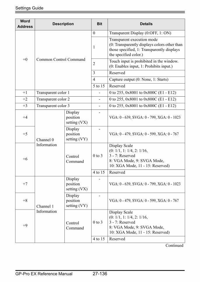
Settings Guide
GP-Pro EX Reference Manual 27-136
Word Address
Description Bit Details
+0 Common Control Command
0 Transparent Display (0:OFF, 1: ON)
1
Transparent execution mode(0: Transparently displays colors other than those specified, 1: Transparently displays the specified color.)
2 Touch input is prohibited in the window.(0: Enables input, 1: Prohibits input.)
3 Reserved4 Capture output (0: None, 1: Starts)5 to 15 Reserved
+1 Transparent color 1 - 0 to 255, 0x8001 to 0x800C (E1 - E12)+2 Transparent color 2 - 0 to 255, 0x8001 to 0x800C (E1 - E12)+3 Transparent color 3 - 0 to 255, 0x8001 to 0x800C (E1 - E12)
+4
Channel 0 Information
Display position setting (VX)
-VGA: 0 - 639, SVGA: 0 - 799, XGA: 0 - 1023
+5Display position setting (VY)
-VGA: 0 - 479, SVGA: 0 - 599, XGA: 0 - 767
+6 Control Command
0 to 3
Display Scale(0: 1/1, 1: 1/4, 2: 1/16, 3 - 7: Reserved 8: VGA Mode, 9: SVGA Mode, 10: XGA Mode, 11 - 15: Reserved)
4 to 15 Reserved
+7
Channel 1 Information
Display position setting (VX)
-VGA: 0 - 639, SVGA: 0 - 799, XGA: 0 - 1023
+8Display position setting (VY)
-VGA: 0 - 479, SVGA: 0 - 599, XGA: 0 - 767
+9 Control Command
0 to 3
Display Scale(0: 1/1, 1: 1/4, 2: 1/16, 3 - 7: Reserved 8: VGA Mode, 9: SVGA Mode, 10: XGA Mode, 11 - 15: Reserved)
4 to 15 ReservedContinued
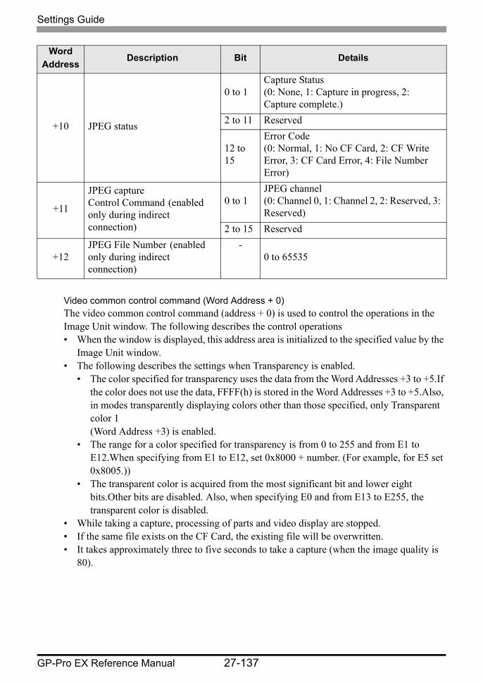
Settings Guide
GP-Pro EX Reference Manual 27-137
Video common control command (Word Address + 0)The video common control command (address + 0) is used to control the operations in the Image Unit window. The following describes the control operations• When the window is displayed, this address area is initialized to the specified value by the
Image Unit window.• The following describes the settings when Transparency is enabled.
• The color specified for transparency uses the data from the Word Addresses +3 to +5.If the color does not use the data, FFFF(h) is stored in the Word Addresses +3 to +5.Also, in modes transparently displaying colors other than those specified, only Transparent color 1 (Word Address +3) is enabled.
• The range for a color specified for transparency is from 0 to 255 and from E1 to E12.When specifying from E1 to E12, set 0x8000 + number. (For example, for E5 set 0x8005.))
• The transparent color is acquired from the most significant bit and lower eight bits.Other bits are disabled. Also, when specifying E0 and from E13 to E255, the transparent color is disabled.
• While taking a capture, processing of parts and video display are stopped.• If the same file exists on the CF Card, the existing file will be overwritten.• It takes approximately three to five seconds to take a capture (when the image quality is
80).
+10 JPEG status
0 to 1Capture Status(0: None, 1: Capture in progress, 2: Capture complete.)
2 to 11 Reserved
12 to 15
Error Code(0: Normal, 1: No CF Card, 2: CF Write Error, 3: CF Card Error, 4: File Number Error)
+11
JPEG captureControl Command (enabled only during indirect connection)
0 to 1JPEG channel(0: Channel 0, 1: Channel 2, 2: Reserved, 3: Reserved)
2 to 15 Reserved
+12JPEG File Number (enabled only during indirect connection)
-0 to 65535
Word Address
Description Bit Details
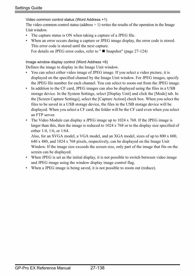
Settings Guide
GP-Pro EX Reference Manual 27-138
Video common control status (Word Address +1)The video common control status (address + 1) writes the results of the operation in the Image Unit window.• The capture status is ON when taking a capture of a JPEG file.• When an error occurs during a capture or JPEG image display, the error code is stored.
This error code is stored until the next capture.For details on JPEG error codes, refer to " Snapshot" (page 27-124)
Image window display control (Word Address +6)Defines the image to display in the Image Unit window.• You can select either video image of JPEG image. If you select a video picture, it is
displayed on the specified channel by the Image Unit window. For JPEG images, specify the JPEG file number for each channel. You can select to zoom out from the JPEG image.
• In addition to the CF card, JPEG images can also be displayed using the files in a USB storage device. In the System Settings, select [Display Unit] and click the [Mode] tab. In the [Screen Capture Settings], select the [Capture Action] check box. When you select the files to be saved in a USB storage device, the files in the USB storage device will be displayed. When you select a CF card, the folder will be the CF card even when you select an FTP server.
• The Video Module can display a JPEG image up to 1024 x 768. If the JPEG image is larger than this, then the image is reduced to 1024 x 768 or to the display size specified of either 1/4, 1/6, or 1/64. Also, for an SVGA model, a VGA model, and an XGA model, sizes of up to 800 x 600, 640 x 480, and 1024 x 768 pixels, respectively, can be displayed on the Image Unit Window. If the image size exceeds the screen size, only part of the image that fits on the screen can be displayed.
• When JPEG is set as the initial display, it is not possible to switch between video image and JPEG image using the window display image control flag.
• When a JPEG image is being saved, it is not possible to zoom out (reduce).
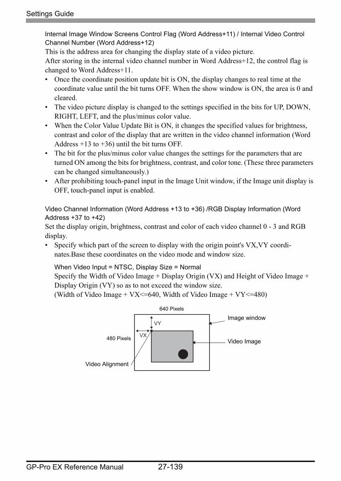
Settings Guide
GP-Pro EX Reference Manual 27-139
Internal Image Window Screens Control Flag (Word Address+11) / Internal Video Control Channel Number (Word Address+12)This is the address area for changing the display state of a video picture.After storing in the internal video channel number in Word Address+12, the control flag is changed to Word Address+11.• Once the coordinate position update bit is ON, the display changes to real time at the
coordinate value until the bit turns OFF. When the show window is ON, the area is 0 and cleared.
• The video picture display is changed to the settings specified in the bits for UP, DOWN, RIGHT, LEFT, and the plus/minus color value.
• When the Color Value Update Bit is ON, it changes the specified values for brightness, contrast and color of the display that are written in the video channel information (Word Address +13 to +36) until the bit turns OFF.
• The bit for the plus/minus color value changes the settings for the parameters that are turned ON among the bits for brightness, contrast, and color tone. (These three parameters can be changed simultaneously.)
• After prohibiting touch-panel input in the Image Unit window, if the Image unit display is OFF, touch-panel input is enabled.
Video Channel Information (Word Address +13 to +36) /RGB Display Information (Word Address +37 to +42)Set the display origin, brightness, contrast and color of each video channel 0 - 3 and RGB display.• Specify which part of the screen to display with the origin point's VX,VY coordi-
nates.Base these coordinates on the video mode and window size.
When Video Input = NTSC, Display Size = NormalSpecify the Width of Video Image + Display Origin (VX) and Height of Video Image + Display Origin (VY) so as to not exceed the window size. (Width of Video Image + VX<=640, Width of Video Image + VY<=480)
VY
VX
Image window
Video Image
640 Pixels
480 Pixels
Video Alignment
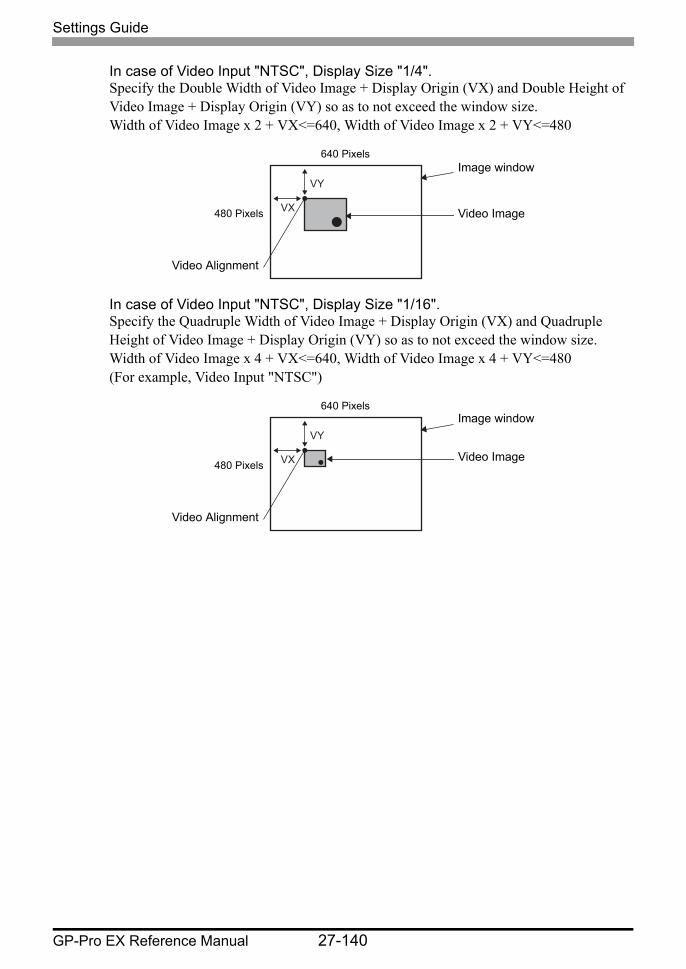
Settings Guide
GP-Pro EX Reference Manual 27-140
In case of Video Input "NTSC", Display Size "1/4".Specify the Double Width of Video Image + Display Origin (VX) and Double Height of Video Image + Display Origin (VY) so as to not exceed the window size. Width of Video Image x 2 + VX<=640, Width of Video Image x 2 + VY<=480
In case of Video Input "NTSC", Display Size "1/16".Specify the Quadruple Width of Video Image + Display Origin (VX) and Quadruple Height of Video Image + Display Origin (VY) so as to not exceed the window size. Width of Video Image x 4 + VX<=640, Width of Video Image x 4 + VY<=480 (For example, Video Input "NTSC")
VY
VX
Image window
Video Image
640 Pixels
480 Pixels
Video Alignment
VY
VX
Image window
Video Image
640 Pixels
480 Pixels
Video Alignment
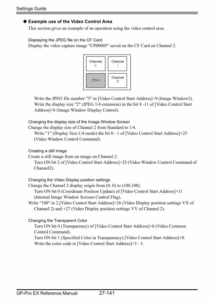
Settings Guide
GP-Pro EX Reference Manual 27-141
Example use of the Video Control AreaThis section gives an example of an operation using the video control area.
Displaying the JPEG file on the CF CardDisplay the video capture image "CP00005" saved on the CF Card on Channel 2.
Write the JPEG file number "5" in [Video Control Start Address]+9 (Image Window2).Write the display size "2" (JPEG 1/4 extension) in the bit 8 -11 of [Video Control Start Address]+6 (Image Window Display Control).
Changing the display size of the Image Window ScreenChange the display size of Channel 2 from Standard to 1/4.
Write "1" (Display Size:1/4 mode) the bit 0 - 1 of [Video Control Start Address]+25 (Video Window Control Command).
Creating a still imageCreate a still image from an image on Channel 2.
Turn ON bit 2 of [Video Control Start Address]+25 (Video Window Control Command of Channel2).
Changing the Video Display position settingsChange the Channel 2 display origin from (0, 0) to (100,100).
Turn ON bit 0 (Coordinate Position Update) of [Video Control Start Address]+11 (Internal Image Window Screens Control Flag).
Write "100" in 2.[Video Control Start Address]+26 (Video Display position settings VX of Channel 2) and +27 (Video Display position settings VY of Channel 2).
Changing the Transparent ColorTurn ON bit 0 (Transparency) of [Video Control Start Address]+0 (Video Common Control Command).Turn ON bit 1 (Specified Color in Transparency) [Video Control Start Address]+0.Write the color code in [Video Control Start Address]+3 - 5.
Channel0
Channel1
JPEG5Channel
3
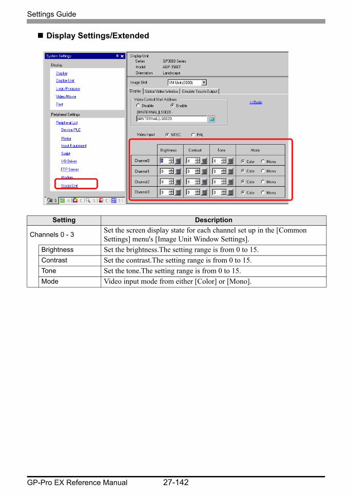
Settings Guide
GP-Pro EX Reference Manual 27-142
Display Settings/Extended
Setting Description
Channels 0 - 3 Set the screen display state for each channel set up in the [Common Settings] menu's [Image Unit Window Settings].
Brightness Set the brightness.The setting range is from 0 to 15.Contrast Set the contrast.The setting range is from 0 to 15.Tone Set the tone.The setting range is from 0 to 15.Mode Video input mode from either [Color] or [Mono].
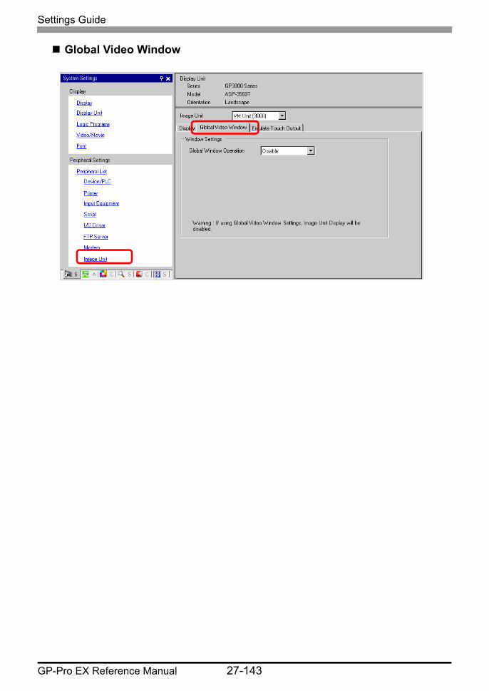
Settings Guide
GP-Pro EX Reference Manual 27-143
Global Video Window
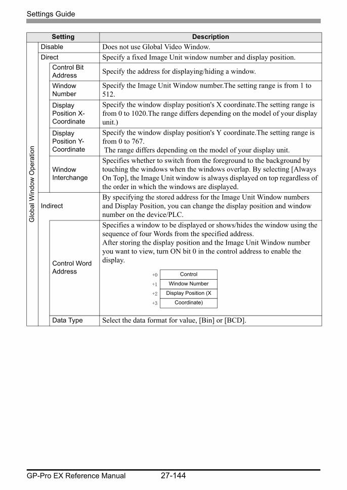
Settings Guide
GP-Pro EX Reference Manual 27-144
Setting DescriptionG
loba
l Win
dow
Ope
ratio
n
Disable Does not use Global Video Window.Direct Specify a fixed Image Unit window number and display position.
Control Bit Address Specify the address for displaying/hiding a window.
Window Number
Specify the Image Unit Window number.The setting range is from 1 to 512.
Display Position X-Coordinate
Specify the window display position's X coordinate.The setting range is from 0 to 1020.The range differs depending on the model of your display unit.)
Display Position Y-Coordinate
Specify the window display position's Y coordinate.The setting range is from 0 to 767. The range differs depending on the model of your display unit.
Window Interchange
Specifies whether to switch from the foreground to the background by touching the windows when the windows overlap. By selecting [Always On Top], the Image Unit window is always displayed on top regardless of the order in which the windows are displayed.
IndirectBy specifying the stored address for the Image Unit Window numbers and Display Position, you can change the display position and window number on the device/PLC.
Control Word Address
Specifies a window to be displayed or shows/hides the window using the sequence of four Words from the specified address.After storing the display position and the Image Unit Window number you want to view, turn ON bit 0 in the control address to enable the display.
Data Type Select the data format for value, [Bin] or [BCD].
Control
Window Number
Display Position (X
Coordinate)
+0
+1
+2
+3

Settings Guide
GP-Pro EX Reference Manual 27-145
Emulate Touch OutputThis allows you to output touch coordinates to a PC using serial communication.To use the PC mouse cursor to emulate touches on the GP, install on the PC mouse emulation software so the PC can receive touch information sent from the GP.
• For the touch output, have the following ready.•Mouse emulation software manufactured by Digital Electronics Corporation
of Japan.•USB communication driver (for RGB Units only) manufactured by Digital
Electronics Corporation of Japan (this software can be downloaded from the support site "Otasuke Pro!" (http://www.proface.co.jp/otasuke).)
•RGB cable (optional or commercially available)•Serial cable, cross (commercially available): VM Unit, DVI Unit•USB cable (optional or commercially available): RGB Unit
Setting DescriptionEmulate Touch Output
Using RGB inputs, select whether or not to output touch coordinates to external devices over serial communication lines.
Port
Select a port for the touch output from either [COM1], [COM2], or [USB/SIO].
• When specifying the port Number to be used, mark ("Duplicate Port") is displayed.
Communication Speed
Select a communication speed from [2400], [4800], [9600], [19200], [38400], [57600] or [115200].
Communication Settings
Select the communication method from [RS-232C], [RS-422/485 (2 wire)], or [RS-422/485 (4 wire)]
Data Length Select the data length from either [7] or [8].Continued
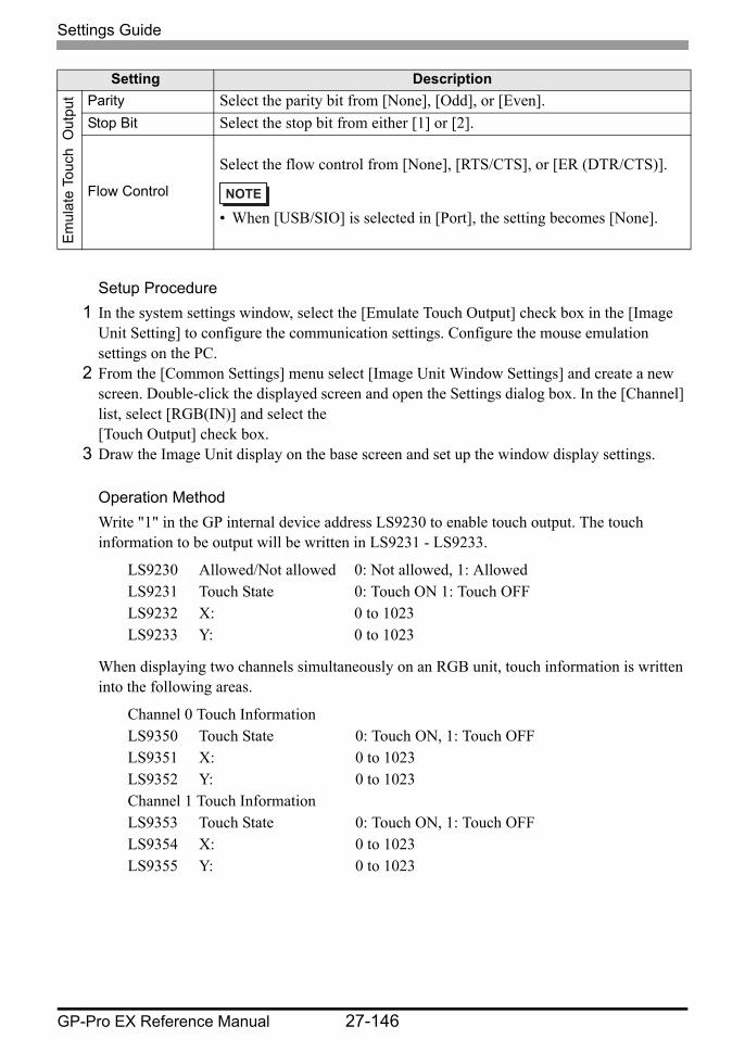
Settings Guide
GP-Pro EX Reference Manual 27-146
Setup Procedure1 In the system settings window, select the [Emulate Touch Output] check box in the [Image
Unit Setting] to configure the communication settings. Configure the mouse emulation settings on the PC.
2 From the [Common Settings] menu select [Image Unit Window Settings] and create a new screen. Double-click the displayed screen and open the Settings dialog box. In the [Channel] list, select [RGB(IN)] and select the [Touch Output] check box.
3 Draw the Image Unit display on the base screen and set up the window display settings.
Operation MethodWrite "1" in the GP internal device address LS9230 to enable touch output. The touch information to be output will be written in LS9231 - LS9233.
When displaying two channels simultaneously on an RGB unit, touch information is written into the following areas.
Em
ulat
e To
uch
Out
put Parity Select the parity bit from [None], [Odd], or [Even].
Stop Bit Select the stop bit from either [1] or [2].
Flow Control
Select the flow control from [None], [RTS/CTS], or [ER (DTR/CTS)].
• When [USB/SIO] is selected in [Port], the setting becomes [None].
LS9230 Allowed/Not allowed 0: Not allowed, 1: AllowedLS9231 Touch State 0: Touch ON 1: Touch OFFLS9232 X: 0 to 1023LS9233 Y: 0 to 1023
Channel 0 Touch InformationLS9350 Touch State 0: Touch ON, 1: Touch OFFLS9351 X: 0 to 1023LS9352 Y: 0 to 1023Channel 1 Touch InformationLS9353 Touch State 0: Touch ON, 1: Touch OFFLS9354 X: 0 to 1023LS9355 Y: 0 to 1023
Setting Description
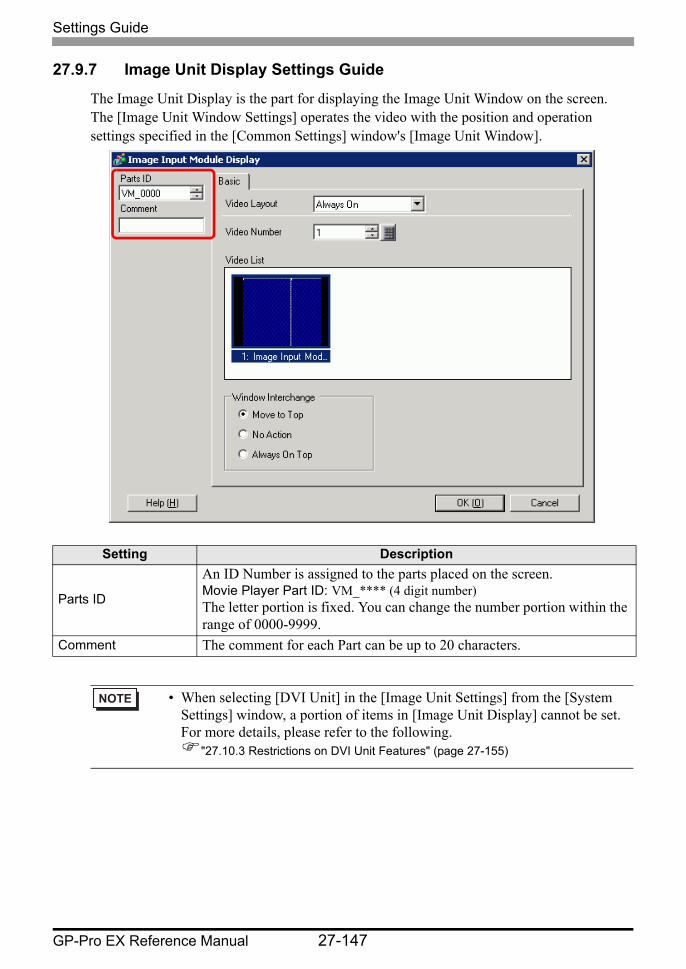
Settings Guide
GP-Pro EX Reference Manual 27-147
27.9.7 Image Unit Display Settings Guide
The Image Unit Display is the part for displaying the Image Unit Window on the screen. The [Image Unit Window Settings] operates the video with the position and operation settings specified in the [Common Settings] window's [Image Unit Window].
Setting Description
Parts ID
An ID Number is assigned to the parts placed on the screen.Movie Player Part ID: VM_**** (4 digit number)The letter portion is fixed. You can change the number portion within the range of 0000-9999.
Comment The comment for each Part can be up to 20 characters.
• When selecting [DVI Unit] in the [Image Unit Settings] from the [System Settings] window, a portion of items in [Image Unit Display] cannot be set. For more details, please refer to the following.
"27.10.3 Restrictions on DVI Unit Features" (page 27-155)
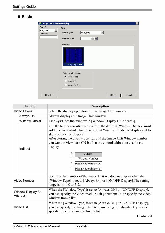
Settings Guide
GP-Pro EX Reference Manual 27-148
Basic
Setting DescriptionVideo Layout Select the display operation for the Image Unit window.
Always On Always displays the Image Unit window.Window On/Off Displays/hides the window in [Window Display Bit Address].
Indirect
Use the four consecutive words from the defined [Window Display Word Address] to control which Image Unit Window number to display and to show or hide the display. After storing the display position and the Image Unit Window number you want to view, turn ON bit 0 in the control address to enable the display.
Video NumberSpecifies the number of the Image Unit window to display when the [Window Type] is set to [Always On] or [ON/OFF Display].The setting range is from 0 to 512.
Window Display Bit Address
When the [Window Type] is set to [Always ON] or [ON/OFF Display], you can specify the video module using thumbnails, or specify the video window from a list.
Video ListWhen the [Window Type] is set to [Always ON] or [ON/OFF Display], you can specify the Image Unit Window using thumbnails.Or you can specify the video window from a list.
Continued
Control
Window Number
Display coordinate (X)
Display coordinate (Y)
+0
+1
+2
+3
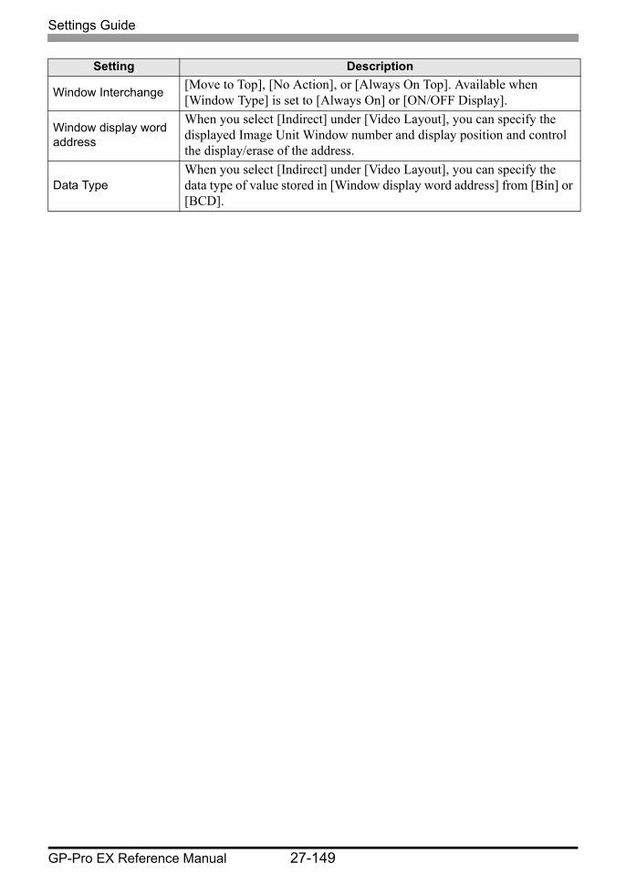
Settings Guide
GP-Pro EX Reference Manual 27-149
Window Interchange [Move to Top], [No Action], or [Always On Top]. Available when [Window Type] is set to [Always On] or [ON/OFF Display].
Window display word address
When you select [Indirect] under [Video Layout], you can specify the displayed Image Unit Window number and display position and control the display/erase of the address.
Data TypeWhen you select [Indirect] under [Video Layout], you can specify the data type of value stored in [Window display word address] from [Bin] or [BCD].
Setting Description

Restrictions
GP-Pro EX Reference Manual 27-150
27.10 Restrictions
Differences Between Movie and Image Unit Features
Items Movie play feature Image Unit Features
Camera for displaying objects
1-ch camera input with AGP-3∗50T
Movie file on the CF/FTP server
4-ch camera input on VM UnitRGB input on an Image Unit
Setup part Movie Player Image Unit Display
Number of simultaneous camera displays
Displays only one image.
The display area can be divided into four areas and the number
of images to be displayed can be selected.
Movie recording function Enable None
JPEG Capture function for movies
None Enable
Camera input signal format NTSC/PAL/SECAM NTSC/PAL

Restrictions
GP-Pro EX Reference Manual 27-151
27.10.1 Restrictions on Movie Features
Movie Player• Only one Movie Player can be placed on one Base Screen or Window Screen.• The width (X coordinate) of the Movie Player can be specified in multiples of four pixels.• If the size of the Movie Player is smaller than the video input image, part of the area that
does not fit the screen will not be displayed. To view the entire image, move the image using the move switch.For example, AGP-3550T (640 x 480)
Video Input is [NTSC] (640 x 480) Movie Player's [Display Size] is [Normal]
• The following table lists the video signal settings, operable cameras, and movie files.
• When returning online after moving to offline mode or transfer mode while a video is being displayed or played, all functions stop. The picture will not be displayed. Touch the video display switch or the play switch to display the video.
• If you record objects moving at high speed, during playback of the video it may look as if the image stops periodically.
Video Signal Setting
Video Signal Movie Player FileMovie Record
FileNTSC NTSC NTSC NTSCPAL PAL PAL PAL
SECAM SECAM PAL PAL
The diagram above shows the area that is not displayed
MoveMovie Player Movie Player
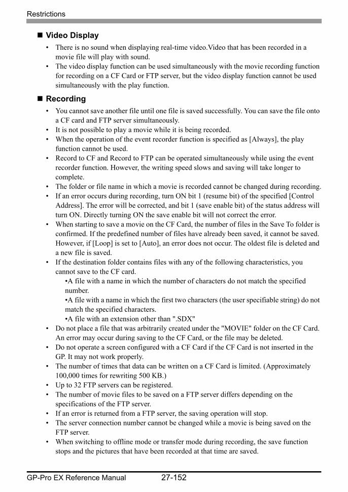
Restrictions
GP-Pro EX Reference Manual 27-152
Video Display• There is no sound when displaying real-time video.Video that has been recorded in a
movie file will play with sound.• The video display function can be used simultaneously with the movie recording function
for recording on a CF Card or FTP server, but the video display function cannot be used simultaneously with the play function.
Recording• You cannot save another file until one file is saved successfully. You can save the file onto
a CF card and FTP server simultaneously.• It is not possible to play a movie while it is being recorded.• When the operation of the event recorder function is specified as [Always], the play
function cannot be used.• Record to CF and Record to FTP can be operated simultaneously while using the event
recorder function. However, the writing speed slows and saving will take longer to complete.
• The folder or file name in which a movie is recorded cannot be changed during recording.• If an error occurs during recording, turn ON bit 1 (resume bit) of the specified [Control
Address]. The error will be corrected, and bit 1 (save enable bit) of the status address will turn ON. Directly turning ON the save enable bit will not correct the error.
• When starting to save a movie on the CF Card, the number of files in the Save To folder is confirmed. If the predefined number of files have already been saved, it cannot be saved. However, if [Loop] is set to [Auto], an error does not occur. The oldest file is deleted and a new file is saved.
• If the destination folder contains files with any of the following characteristics, you cannot save to the CF card.
•A file with a name in which the number of characters do not match the specified number.•A file with a name in which the first two characters (the user specifiable string) do not match the specified characters.•A file with an extension other than ".SDX"
• Do not place a file that was arbitrarily created under the "MOVIE" folder on the CF Card. An error may occur during saving to the CF Card, or the file may be deleted.
• Do not operate a screen configured with a CF Card if the CF Card is not inserted in the GP. It may not work properly.
• The number of times that data can be written on a CF Card is limited. (Approximately 100,000 times for rewriting 500 KB.)
• Up to 32 FTP servers can be registered.• The number of movie files to be saved on a FTP server differs depending on the
specifications of the FTP server.• If an error is returned from a FTP server, the saving operation will stop.• The server connection number cannot be changed while a movie is being saved on the
FTP server.• When switching to offline mode or transfer mode during recording, the save function
stops and the pictures that have been recorded at that time are saved.
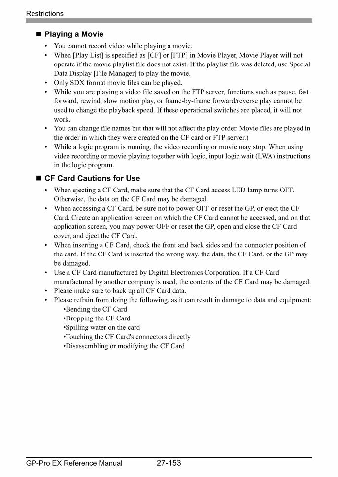
Restrictions
GP-Pro EX Reference Manual 27-153
Playing a Movie• You cannot record video while playing a movie.• When [Play List] is specified as [CF] or [FTP] in Movie Player, Movie Player will not
operate if the movie playlist file does not exist. If the playlist file was deleted, use Special Data Display [File Manager] to play the movie.
• Only SDX format movie files can be played.• While you are playing a video file saved on the FTP server, functions such as pause, fast
forward, rewind, slow motion play, or frame-by-frame forward/reverse play cannot be used to change the playback speed. If these operational switches are placed, it will not work.
• You can change file names but that will not affect the play order. Movie files are played in the order in which they were created on the CF card or FTP server.)
• While a logic program is running, the video recording or movie may stop. When using video recording or movie playing together with logic, input logic wait (LWA) instructions in the logic program.
CF Card Cautions for Use• When ejecting a CF Card, make sure that the CF Card access LED lamp turns OFF.
Otherwise, the data on the CF Card may be damaged.• When accessing a CF Card, be sure not to power OFF or reset the GP, or eject the CF
Card. Create an application screen on which the CF Card cannot be accessed, and on that application screen, you may power OFF or reset the GP, open and close the CF Card cover, and eject the CF Card.
• When inserting a CF Card, check the front and back sides and the connector position of the card. If the CF Card is inserted the wrong way, the data, the CF Card, or the GP may be damaged.
• Use a CF Card manufactured by Digital Electronics Corporation. If a CF Card manufactured by another company is used, the contents of the CF Card may be damaged.
• Please make sure to back up all CF Card data.• Please refrain from doing the following, as it can result in damage to data and equipment:
•Bending the CF Card•Dropping the CF Card•Spilling water on the card•Touching the CF Card's connectors directly•Disassembling or modifying the CF Card
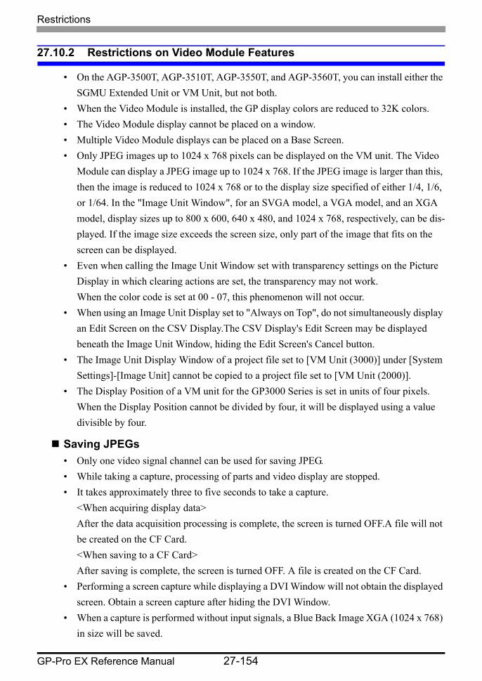
Restrictions
GP-Pro EX Reference Manual 27-154
27.10.2 Restrictions on Video Module Features
• On the AGP-3500T, AGP-3510T, AGP-3550T, and AGP-3560T, you can install either the SGMU Extended Unit or VM Unit, but not both.
• When the Video Module is installed, the GP display colors are reduced to 32K colors.• The Video Module display cannot be placed on a window.• Multiple Video Module displays can be placed on a Base Screen.• Only JPEG images up to 1024 x 768 pixels can be displayed on the VM unit. The Video
Module can display a JPEG image up to 1024 x 768. If the JPEG image is larger than this, then the image is reduced to 1024 x 768 or to the display size specified of either 1/4, 1/6, or 1/64. In the "Image Unit Window", for an SVGA model, a VGA model, and an XGA model, display sizes up to 800 x 600, 640 x 480, and 1024 x 768, respectively, can be dis-played. If the image size exceeds the screen size, only part of the image that fits on the screen can be displayed.
• Even when calling the Image Unit Window set with transparency settings on the Picture Display in which clearing actions are set, the transparency may not work. When the color code is set at 00 - 07, this phenomenon will not occur.
• When using an Image Unit Display set to "Always on Top", do not simultaneously display an Edit Screen on the CSV Display.The CSV Display's Edit Screen may be displayed beneath the Image Unit Window, hiding the Edit Screen's Cancel button.
• The Image Unit Display Window of a project file set to [VM Unit (3000)] under [System Settings]-[Image Unit] cannot be copied to a project file set to [VM Unit (2000)].
• The Display Position of a VM unit for the GP3000 Series is set in units of four pixels. When the Display Position cannot be divided by four, it will be displayed using a value divisible by four.
Saving JPEGs• Only one video signal channel can be used for saving JPEG.• While taking a capture, processing of parts and video display are stopped.• It takes approximately three to five seconds to take a capture.
<When acquiring display data>After the data acquisition processing is complete, the screen is turned OFF.A file will not be created on the CF Card.<When saving to a CF Card>After saving is complete, the screen is turned OFF. A file is created on the CF Card.
• Performing a screen capture while displaying a DVI Window will not obtain the displayed screen. Obtain a screen capture after hiding the DVI Window.
• When a capture is performed without input signals, a Blue Back Image XGA (1024 x 768) in size will be saved.
Restrictions
GP-Pro EX Reference Manual 27-155
27.10.3 Restrictions on DVI Unit Features
• You cannot save in JPG format or display the data in JPG format.• You cannot capture the video screen.• When selecting [DVI Unit] in the [Image Unit Setting] even when the Video Module Unit
is installed, video input is invalid.The settings items are not displayed. Also detailed settings for the video signal settings are not displayed.
• When an Image Unit Display is set to "Always on Top", do not work with the CSV Display at the same time as the editor. The CSV Display's editor screen display below the Image Unit Window, hiding the Cancel button.
• If the input screen has a higher resolution than the GP, it will display only a portion of the image. Please adjust the resolution of the PC to match the GP.
Image Unit Window settings• Because the DVI input screen is always displayed, the spacing is disabled and the window
type is fixed to one screen display. Also, in the channel settings, it will be fixed to RGB Input Image.
• The display size will be operated only under normal settings.• In the DVI Input display, the area to be the background does not exist and so the
background color settings are disabled.• Video capture action is invalid. Also, processes related to JPEGs are disabled.
Restrictions
GP-Pro EX Reference Manual 27-156