252 ieee transactions on plasma science, vol. … · 252 ieee transactions on plasma science, vol....
TRANSCRIPT
252 IEEE TRANSACTIONS ON PLASMA SCIENCE, VOL. 43, NO. 1, JANUARY 2015
Investigation of Plasma Detachment Froma Magnetic Nozzle in the Plume of the
VX-200 Magnetoplasma ThrusterChristopher S. Olsen, Maxwell G. Ballenger, Mark D. Carter, Franklin R. Chang Díaz, Matthew Giambusso,
Timothy W. Glover, Andrew V. Ilin, Jared P. Squire, Benjamin W. Longmier,Edgar A. Bering, III, and Paul A. Cloutier
Abstract— Understanding the physics involved in plasmadetachment from magnetic nozzles is well theorized, but lackingin large scale experimental support. We have undertaken anexperiment using the 150-m3 variable specific impulse mag-netoplasma rocket test facility and VX-200 thruster seekingevidence that detachment occurs and an understanding of thephysical processes involved. It was found that the plasma jet inthis experiment does indeed detach from the applied magneticnozzle (peak field ∼2 T) in a two part process. The first partinvolves the ions beginning to deviate from the nozzle field0.8-m downstream of the nozzle throat. This separation locationis consistent with a loss of adiabaticity where the ratio of theion Larmor radius to the magnetic field scale length (rLi |∇B|/B)becomes of order unity and conservation of the magnetic momentbreaks down. Downstream of this separation region, the dynamicsof the unmagnetized ions and magnetized electrons, along withthe ion momentum, affect the plume trajectory. The second partof the process involves the formation of plasma turbulence inthe form of high-frequency electric fields. The ion and electronresponses to these electric fields depend upon ion momentum,magnetic field line curvature, magnetic field strength, anglebetween the particle trajectories, and the effective momentumtransfer time. In stronger magnetic field regions of the nozzle, thedetached ion trajectories are affected such that the unmagnetizedions begin to flare radially outward. Further downstream as themagnetic field weakens, for higher ion momentum and along theedge of the plume, the fluctuating electric field enables anomalouscross-field electron transport to become more dominant. Thiscross-field transport occurs until the electric fields dissipate∼2-m downstream of the nozzle throat and the ion trajectoriesbecome ballistic. This transition to ballistic flow correlates wellwith the sub-to-super Alfvénic flow transition (βk). There wasno significant change observed to the applied magnetic field.
Manuscript received November 21, 2013; revised January 28, 2014 andMarch 25, 2014; accepted April 22, 2014. Date of publication May 30, 2014;date of current version January 6, 2015.
C. S. Olsen, M. G. Ballenger, M. D. Carter, F. R. C. Díaz, M. Giambusso,T. W. Glover, A. V. Ilin, and J. P. Squire are with Ad Astra RocketCompany, Webster, TX 77598 USA (e-mail: [email protected];[email protected]; [email protected]; [email protected]; [email protected]; [email protected];[email protected]; [email protected]).
B. W. Longmier is with the Department of Aerospace Engineering, Univer-sity of Michigan, Ann Arbor, MI 48109 USA (e-mail: [email protected]).
E. A. Bering, III is with the Department of Physics and Department ofElectronics and Communications, University of Houston, Houston, TX 77204USA (e-mail: [email protected]).
P. A. Cloutier is with the Department of Physics and Astronomy, RiceUniversity, Houston, TX 77005 USA (e-mail: [email protected]).
Color versions of one or more of the figures in this paper are availableonline at http://ieeexplore.ieee.org.
Digital Object Identifier 10.1109/TPS.2014.2321257
Index Terms— Argon, electromagnetic propagation in plasmamedia, magnetic field measurement, magnetohydrodynamics,magnetometers, physics, plasma applications, plasma engines,plasma measurements, plasma waves.
NOMENCLATURE
ICH Ion cyclotron heating.�c,e,i Generic, electron, ion cyclotron frequency.βk,th Kinetic, thermal beta.B Magnetic flux density [G].D Diffusion coefficient [m2/s].μ Mobility [m2/V/s].ν Collision frequency [Hz].S, L External ionization sources/losses [ions/s/m2].u, vi Ion velocity [m/s].η Plasma resistivity [ohm].ude Drift velocity of electrons relative to ions [m/s].τeff Effective momentum transfer time [s].redge Projected magnetic plasma boundary [m].V Test particle velocity [m/s].u⊥ Cross-field electron velocity [m/s].uE E × B drift velocity [m/s].u D Diamagnetic drift velocity [m/s].φ(x) Error function.ψ(x) First derivative of error function.Rc Radius of curvature [m].iz Axial ion flux [ions/s].B Axial magnetic flux [Wb].Jiz Axial current density [A/m2].fi Ion flux plume fraction.f Magnetic flux plume fraction.rL Larmor radius [m].E Electric field [V/m].q Elementary charge [C].Ei Ion energy [eV].ρ Mass density [kg/m3].fLH Lower hybrid frequency [Hz].me,i Electron, ion mass [kg].ne Electron density [m−3].Te Electron temperature [eV].kB Boltzmann constant [erg/eV].ε0 Permittivity of free space [F/C].ln Coulomb logarithm.θ Pitch, divergence angle [°].
0093-3813 © 2014 IEEE. Personal use is permitted, but republication/redistribution requires IEEE permission.See http://www.ieee.org/publications_standards/publications/rights/index.html for more information.
OLSEN et al.: INVESTIGATION OF PLASMA DETACHMENT FROM A MAGNETIC NOZZLE 253
I. INTRODUCTION
PLASMA flowing through magnetic nozzles has beenobserved in many natural systems and is used in a variety
of terrestrial applications ranging from plasma processing toelectric propulsion [1], [2]. Similar to de Laval nozzles thatconvert random thermal motion into directed flow, magneticnozzles are used to redirect the motion and momentum of theplasma flowing through the nozzle. To this end, a magneticnozzle can be used to improve thrust efficiency and provide ameans of controlling the plume geometry and plasma energydistribution functions. One issue facing the implementationof magnetic nozzles is the tendency of the plasma to remainmagnetized or otherwise tied to the magnetic field linesforming the nozzle. Many theories have been proposed toaddress the physics of the plasma detachment process frommagnetic nozzles that range from collisional resistive diffusion[3] to collisionless magnetohydrodynamic (MHD) field linestretching [4], [5], loss of adiabaticity [6], [7], and electroninertia [8], [9]. Despite the many theories attempting to explainthis process, there has been an overall dearth of qualityexperimental data to fully support any one mechanism, and asa result knowledge of the physics of magnetic nozzles remainslimited.
One device that is ideally suited to study the processesinvolved in magnetic nozzle plasma detachment is the variablespecific impulse magnetoplasma rocket (VASIMR) VX-200laboratory device [10]. A dipole-expanding magnetic nozzle isinherent to the design and the ion cyclotron resonance processin the second stage of the plasma rocket allows control of theion energy, thus permitting the investigation into momentum-dependent detachment processes. Other main benefits of usingthis device are that it is situated within a 150-m3 vacuumfacility where the plume is able to expand for several metersbefore terminating on any material surface, the pumping rateis sufficient to keep background neutral pressures low enoughto minimize charge–exchange processes, and ramping to fullpower plasma operation within 100 ms is routine. An extensiveexperiment campaign where detailed mapping of the plasmaplume in a volume extending more than 2-m downstreamof the exhaust exit has been completed using the VASIMRVX-200 device operating at two power levels; 30 ± 0.4 and100 ± 2 kW corresponding to the first stage helicon dischargealone and both stages together, respectively [2]. Data weretaken during the early portions of the discharge, while back-ground pressure remained below 2 × 10⁻⁴ torr. A variety oftraditional plasma diagnostics were used to gather plume data.The plume mapping was performed by repositioning each ofthe diagnostics using a 2-axis step-motor driven translationstage with submillimeter resolution. The spatially dependentplume data were then analyzed to verify if separation of theplasma from the applied magnetic field had occurred andwhich of the leading detachment theories were most consistentwith the data. This paper shall attempt to summarize thehighlights of this experiment and provide new key insightsinto the physics of energized plasma flowing through an axialmagnetic nozzle.
The rest of this paper is organized as follows. Section IIdescribes the key components of the experiment, such as
the plasma source, environmental conditions, and plasmadiagnostics showing that the setup is legitimate and the datataken is of high quality. Section III discusses the results ofthe data characterizing the behavior of the plume flowingin the conditions listed in Section II. Section IV concludesthis paper with some of the general outcomes of the work,while proposing some future experiments and applications ofmagnetic nozzles.
II. EXPERIMENTAL SETUP
A laboratory experiment set on adequately measuring andquantifying the physics involved in the final stages of plasmaflowing through a magnetic nozzle, the separation of themagnetized plasma from the field lines that form the nozzle,should have to meet a number of specific required conditions[1], [11]. The first of which is that the system be large enoughfor the detachment process to occur and that it have amplevolume for the plume to expand unimpeded before neutralizingon the walls of the chamber. The second requirement is tohave sufficiently low-vacuum conditions so as to minimizeplasma to neutral interactions (e.g., particle sources and lossesdue to impact ionization or charge–exchange interactions),which will alter unimpeded fluxes and potentially mask theunderlying physics. A third requirement involves exploringover an adequate scale length for a magnetic nozzle wherethe magnetic field strengths extend a few orders of magnitudeso as to test over a wide range of potential physical processes.Finally, the experiment should be capable of measuring therelevant plasma properties across the scale length of the systemenough to characterize the detachment process. The followingsections will address that each of these requirements weremet during our experiment. We begin with an overview of theplasma source and magnetic nozzle followed by descriptionsof the vacuum facility used to create the proper conditions andplasma diagnostics needed to measure the plasma.
A. VASIMR VX-200 Engine
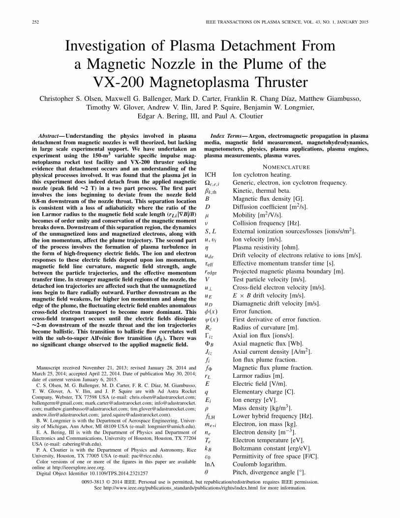
The VASIMR engine is a high-power electric propulsionsystem capable of varying the thrust and specific impulse,while operating at a fixed input power. This form of constantpower throttling makes the VASIMR engine an attractiveoption for a wide range of prospective space missions. Themain components of a VASIMR engine are the engine core,propellant source, magnet, and RF generators and are shownin Fig. 1. A key benefit in using the VASIMR engine to studymagnetic nozzles is the magnetic field inherent to the design.The properly shaped field profile enables radio frequency (RF)wave transport and forms a dipole (far field) expanding nozzle.Plasma is generated by a 6.78-MHz high-power helicon[11]–[17], which serves as the first stage of the engine core.The second stage, known as ion cyclotron heating (ICH),energizes the ions by launching left-hand polarized slow modewaves from the high-field side of ion resonance [18]–[20]. ThisRF wave coupling mechanism requires that the plasma be fullymagnetized and enables control of the ion velocity exiting thethruster.
254 IEEE TRANSACTIONS ON PLASMA SCIENCE, VOL. 43, NO. 1, JANUARY 2015
Fig. 1. Conceptual schematic of the VASIMR engine.
The VX-200 (VASIMR experimental—200 kW) deviceis a laboratory prototype operating from 2009 to 2012demonstrating high-power densities (6 MW/m2 across the exitarea), specific impulse ranging between 2000 and 5000 s, andthrust up to 6 N. The magnetic field is generated by a cryogen-free, first generation (Nb-Ti) superconducting magnet encasedin a well-insulated cryostat surrounding the engine core.It features a lightweight design and was fabricated by Scien-tific Magnetics of Oxford England, and produces a peak mag-netic field strength of 2 T. The RF power is generated from twohigh-efficiency solid-state generators (combined conversionefficiency of 95% dc to RF) manufactured by Nautel Limitedof Canada, and are independently controlled [21]. Impedancematching circuits are used to couple up to 98% of the RFpower into the plasma. The RF generators are controlled usingan in-house developed Field Programmable Gate Array circuitthat provides precise synchronization between the units. Argonpropellant is regulated through an injector plate into the firststage using a Moog propellant manifold. The manifold con-tains a proportional flow control valve, Taber industries low-pressure transducer, and a 0.041” diameter orifice flow con-troller. Choked flow enables mass flow rates up to 5000 sccm(∼150 mg/s), which are verified using an in-line calibrated,NIST traceable, MKS-179 thermal mass flow controller.While the magnetic field is consistently active, timing of thegas flow, RF power, and plasma diagnostic are performedusing a fiber optic triggering system synchronizing eachsystem to within 6 ms from receiving the command.
B. Vacuum Facility
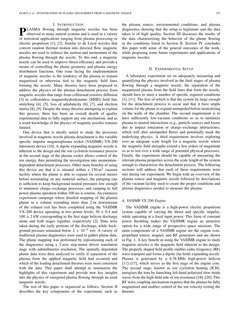
The experiment was carried out in a stainless steel vacuumchamber that is 4.3 m in diameter and 10-m long with avolume of 150 m3 (including the end caps) located at theAd Astra Rocket Company’s Houston facility (Fig. 2). Oneend opens fully for complete access to the inner diameter ofthe chamber. The chamber is partitioned into two regions:1) a rocket region and 2) a plume region. An anodizedaluminum framed wall with Lexan paneling serves as the
Fig. 2. Semitransparent schematic of the 10-m long × 4.3-m diametervacuum chamber and the VX-200 engine. Also shown are the translation stage,cryopumps, and locations of the measurement region and vacuum partition.All axial coordinates reference the end flange of the chamber.
partition, which is located at 2.613 m (nozzle throat is at∼2.08 m) with Z = 0 m defined at the chamber door flange.The VX-200 engine is installed in the forward section of thechamber where a separate cryopump is used to maintain alower pressure during firings so as to prevent arcing and glowdischarges from forming near high-voltage RF components.The majority of the VX-200 components are located within thevacuum chamber with only the RF generators, magnet powersupplies, and magnet cryocoolers maintained at atmosphericpressure. The plume region contains four CVI Torr-Master1200i cryopumps, although for this experiment only three wereused for a cumulative argon pumping speed of 175 000 L/s andan ultimate pressure of ∼1 × 10⁻⁸ torr. The normal baselinepressure in between firings is ∼5 × 10⁻⁸ torr and rises as highas 2 × 10⁻⁴ torr argon after 1 s of plasma operation. Pressuresin the plume region are measured using three separate hotcathode ion gauges.
C. Diagnostics and Translation Stage
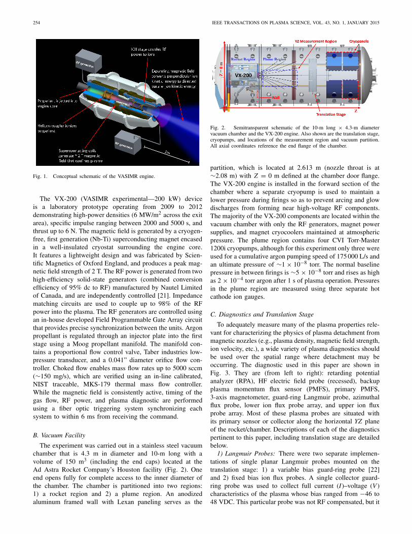
To adequately measure many of the plasma properties rele-vant for characterizing the physics of plasma detachment frommagnetic nozzles (e.g., plasma density, magnetic field strength,ion velocity, etc.), a wide variety of plasma diagnostics shouldbe used over the spatial range where detachment may beoccurring. The diagnostic used in this paper are shown inFig. 3. They are (from left to right): retarding potentialanalyzer (RPA), HF electric field probe (recessed), backupplasma momentum flux sensor (PMFS), primary PMFS,3-axis magnetometer, guard-ring Langmuir probe, azimuthalflux probe, lower ion flux probe array, and upper ion fluxprobe array. Most of these plasma probes are situated withits primary sensor or collector along the horizontal YZ planeof the rocket/chamber. Descriptions of each of the diagnosticspertinent to this paper, including translation stage are detailedbelow.
1) Langmuir Probes: There were two separate implemen-tations of single planar Langmuir probes mounted on thetranslation stage: 1) a variable bias guard-ring probe [22]and 2) fixed bias ion flux probes. A single collector guard-ring probe was used to collect full current (I)–voltage (V )characteristics of the plasma whose bias ranged from −46 to48 VDC. This particular probe was not RF compensated, but it
OLSEN et al.: INVESTIGATION OF PLASMA DETACHMENT FROM A MAGNETIC NOZZLE 255
Fig. 3. Image of plasma diagnostics mounted on the translation stage.
has been characterized [23] under similar RF conditions tothis experiment and the uncertainty is propagated through thedata. The collector is surrounded by a stainless steel guard-ringat a gap distance of 0.13 mm to minimize sheath expansioneffects. A pair of ten-collector fixed bias Langmuir probearrays, spaced orthogonally along an alumina tube (Fig. 3),were used to measure ion flux. These ion flux probes werebiased at −20 VDC into the ion saturation regime, which wasverified to be 3Te more negative than the floating potentialduring each firing using the guard-ring I–V characteristics.The collectors for all of the Langmuir probes consisted ofhigh-purity 0.64-cm diameter molybdenum machined into aterraced design [24]. The Debye length, λD , in the plasma ismuch smaller than all collector dimensions (λD < 15 μm) andorbit limited collection is not a concern.
2) Plasma Momentum Flux Sensor: The PMFS was used tomeasure the amount of force imparted to the thruster carriedaway within the plasma stream. This method of measuringforce has been characterized elsewhere [25], [27] and is aninexpensive alternative to traditional inverted pendulum thruststands comparing well using the P5 Hall thruster [28]. ThePMFS consists of a 9-cm diameter pyrolitic graphite discattached to a 0.1 cm × 0.1 cm × 10 cm insulating alumina rod.The opposite end of this stiff shaft is mechanically attached toa 5.7 cm × 1.3 cm titanium bar where four Czochralski pulledboron doped silicon strain gauges are fixed to the titanium andconnected in a Wheatstone bridge configuration. The outputvoltage is directly proportional to the amount of force causingstrain. A small graphite shield is used to shadow the titaniumbar/strain gauge assembly from the flowing plasma. The sensoris calibrated using tension applied from a set of precisionmasses and has a resolution of 0.1 mN. The probe has a naturalfrequency of oscillations of ∼40 Hz and at least 3–4 periods(∼100 ms) were averaged at minimum during data analysis.
3) Retarding Potential Analyzer: An RPA was usedto deduce information about the ion distribution function(e.g., the parallel ion energy and temperature). This instrumentwas designed and maintained by the University of Houstonand featured a four double grid arrangement [19]. The gridsconsisted of 35.4-wires/cm nickel mesh and spaced 0.1 cmapart using alumina spacers. Plasma passes through a 1-cmdiameter graphite aperture before encountering an attenuationgrid, a primary electron suppressor, an ion discriminator ora sweep grid, and a secondary electron suppressor beforeterminating on a molybdenum collector. The attenuation gridreduces the plasma density to permit the primary electronsuppressor to repel incoming electrons. A variable bias voltageon the ion discriminator repels ions with flow kinetic energiesbelow this retarding electrostatic potential, while those abovewill reach the collector. A secondary electron suppressorremoves downstream electrons formed from secondary effects(i.e., secondary electron emission). The ion exhaust veloc-ity and temperature are deduced from the current-retardingpotential data using least-squares fits of drifting Maxwellians,which are a common analytical method for spacecraft RPAdata [29], [30]. This RPA was mounted at the end of astep-motor driven goniometer, which permitted up to 90°articulation of the RPA head and analysis of parallel toperpendicular ion pitch angles. It has been estimated that thisRPA is able to resolve multiple component ion populationsas well as multiply ionized species, appearing as a steppedI–V characteristic, and are analyzed by fitting a multicompo-nent distribution [16], [31].
4) Magnetometer: Magnetic field measurements were madeusing an F. W. Bell 7030 Gauss/Tesla Meter using a ZOF73-3208-30-T 3-axis Hall probe. The Hall sensor elements arearranged orthogonally at the end of a 20.3-cm long aluminumfixture. Each Hall sensor has a capable range of 0–30 kG, aresolution of 0.1 mG, and is accurate to within 2%. The sen-sors are temperature compensated correcting to approximately−0.05%/°C of temperature change. The Hall probe itself wasthermally protected from the plasma flow as it was mountedwithin a round capped alumina sleeve in addition to beingshadowed by a 3.8-cm diameter graphite disk (Fig. 3). Thisinstrument may be used to measure magnetic fields from dc upto 50 kHz. A malfunction on one of the axis during an earlierdetachment experiment made it necessary to have the instru-ment recalibrated. The 3-axis probe, full cable assemblies, andelectronics box were calibrated to the ISO/EIC 17025 standard,which is the most rigorous and legally traceable calibrationstandard offered for this instrument. The experiment wasrepeated at a slightly lower mass flow rate.
5) High-Frequency Electric Field Probe: Having adequateinformation on the electric field, particularly the oscillatingelectric field, is important when studying charged particleflows. Knowledge of the range of frequencies and magnitudeof electric fields in the plasma is telling to particle transportand instabilities that may exist throughout the magnetic nozzlesystem. The probe used to measure the oscillating electric fieldwas designed and fabricated by the Alfvén lab in Stockholmand have used this type of probe previously to measure high-frequency electric characteristics in a plasma gun [32], [33].
256 IEEE TRANSACTIONS ON PLASMA SCIENCE, VOL. 43, NO. 1, JANUARY 2015
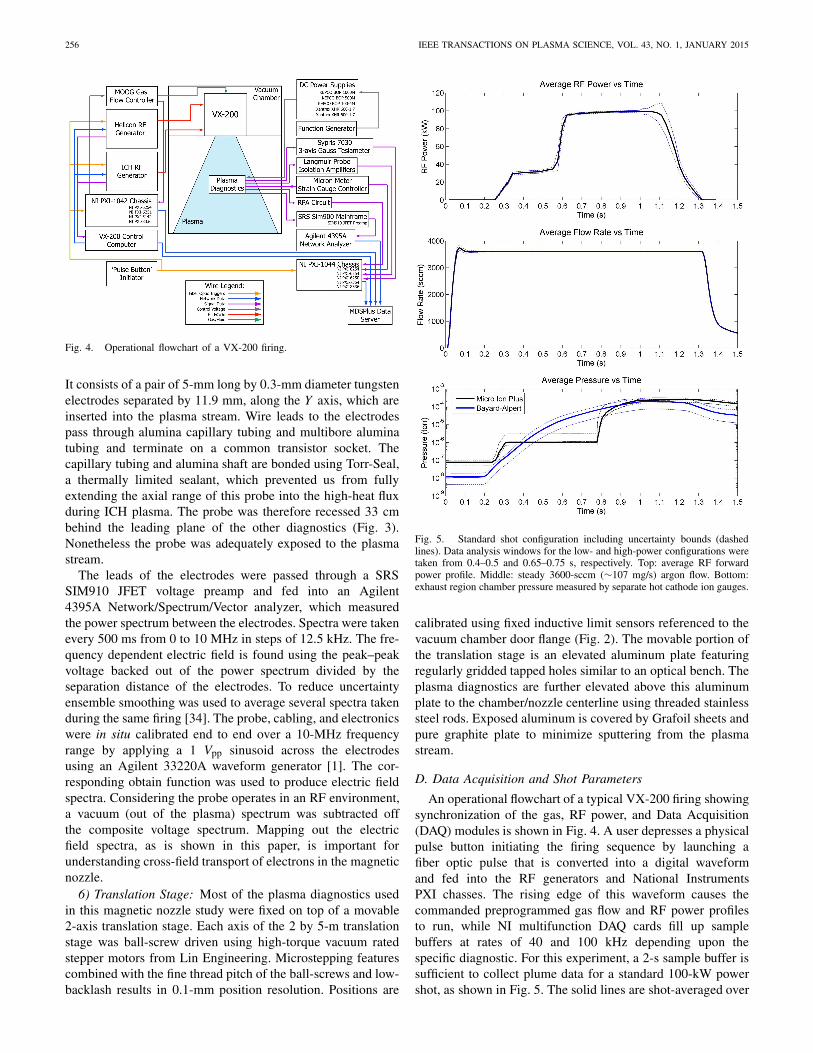
Fig. 4. Operational flowchart of a VX-200 firing.
It consists of a pair of 5-mm long by 0.3-mm diameter tungstenelectrodes separated by 11.9 mm, along the Y axis, which areinserted into the plasma stream. Wire leads to the electrodespass through alumina capillary tubing and multibore aluminatubing and terminate on a common transistor socket. Thecapillary tubing and alumina shaft are bonded using Torr-Seal,a thermally limited sealant, which prevented us from fullyextending the axial range of this probe into the high-heat fluxduring ICH plasma. The probe was therefore recessed 33 cmbehind the leading plane of the other diagnostics (Fig. 3).Nonetheless the probe was adequately exposed to the plasmastream.
The leads of the electrodes were passed through a SRSSIM910 JFET voltage preamp and fed into an Agilent4395A Network/Spectrum/Vector analyzer, which measuredthe power spectrum between the electrodes. Spectra were takenevery 500 ms from 0 to 10 MHz in steps of 12.5 kHz. The fre-quency dependent electric field is found using the peak–peakvoltage backed out of the power spectrum divided by theseparation distance of the electrodes. To reduce uncertaintyensemble smoothing was used to average several spectra takenduring the same firing [34]. The probe, cabling, and electronicswere in situ calibrated end to end over a 10-MHz frequencyrange by applying a 1 Vpp sinusoid across the electrodesusing an Agilent 33220A waveform generator [1]. The cor-responding obtain function was used to produce electric fieldspectra. Considering the probe operates in an RF environment,a vacuum (out of the plasma) spectrum was subtracted offthe composite voltage spectrum. Mapping out the electricfield spectra, as is shown in this paper, is important forunderstanding cross-field transport of electrons in the magneticnozzle.
6) Translation Stage: Most of the plasma diagnostics usedin this magnetic nozzle study were fixed on top of a movable2-axis translation stage. Each axis of the 2 by 5-m translationstage was ball-screw driven using high-torque vacuum ratedstepper motors from Lin Engineering. Microstepping featurescombined with the fine thread pitch of the ball-screws and low-backlash results in 0.1-mm position resolution. Positions are
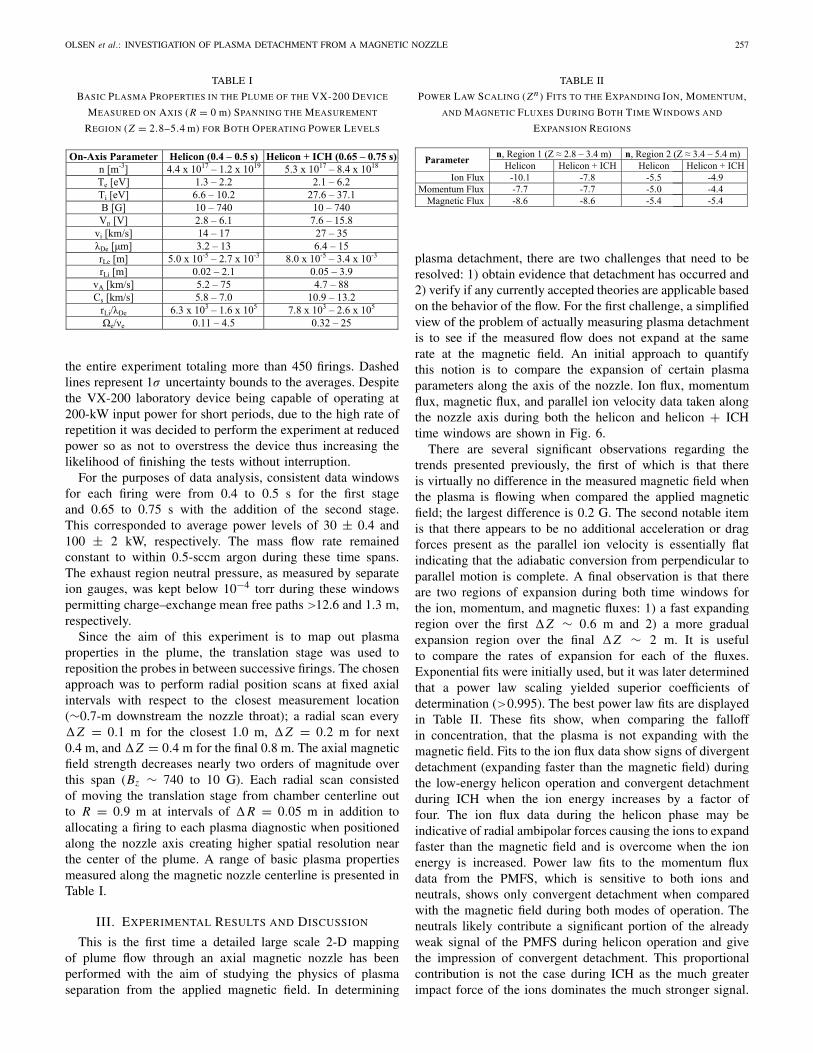
Fig. 5. Standard shot configuration including uncertainty bounds (dashedlines). Data analysis windows for the low- and high-power configurations weretaken from 0.4–0.5 and 0.65–0.75 s, respectively. Top: average RF forwardpower profile. Middle: steady 3600-sccm (∼107 mg/s) argon flow. Bottom:exhaust region chamber pressure measured by separate hot cathode ion gauges.
calibrated using fixed inductive limit sensors referenced to thevacuum chamber door flange (Fig. 2). The movable portion ofthe translation stage is an elevated aluminum plate featuringregularly gridded tapped holes similar to an optical bench. Theplasma diagnostics are further elevated above this aluminumplate to the chamber/nozzle centerline using threaded stainlesssteel rods. Exposed aluminum is covered by Grafoil sheets andpure graphite plate to minimize sputtering from the plasmastream.
D. Data Acquisition and Shot Parameters
An operational flowchart of a typical VX-200 firing showingsynchronization of the gas, RF power, and Data Acquisition(DAQ) modules is shown in Fig. 4. A user depresses a physicalpulse button initiating the firing sequence by launching afiber optic pulse that is converted into a digital waveformand fed into the RF generators and National InstrumentsPXI chasses. The rising edge of this waveform causes thecommanded preprogrammed gas flow and RF power profilesto run, while NI multifunction DAQ cards fill up samplebuffers at rates of 40 and 100 kHz depending upon thespecific diagnostic. For this experiment, a 2-s sample buffer issufficient to collect plume data for a standard 100-kW powershot, as shown in Fig. 5. The solid lines are shot-averaged over
OLSEN et al.: INVESTIGATION OF PLASMA DETACHMENT FROM A MAGNETIC NOZZLE 257
TABLE I
BASIC PLASMA PROPERTIES IN THE PLUME OF THE VX-200 DEVICE
MEASURED ON AXIS (R = 0 m) SPANNING THE MEASUREMENT
REGION (Z = 2.8–5.4 m) FOR BOTH OPERATING POWER LEVELS
the entire experiment totaling more than 450 firings. Dashedlines represent 1σ uncertainty bounds to the averages. Despitethe VX-200 laboratory device being capable of operating at200-kW input power for short periods, due to the high rate ofrepetition it was decided to perform the experiment at reducedpower so as not to overstress the device thus increasing thelikelihood of finishing the tests without interruption.
For the purposes of data analysis, consistent data windowsfor each firing were from 0.4 to 0.5 s for the first stageand 0.65 to 0.75 s with the addition of the second stage.This corresponded to average power levels of 30 ± 0.4 and100 ± 2 kW, respectively. The mass flow rate remainedconstant to within 0.5-sccm argon during these time spans.The exhaust region neutral pressure, as measured by separateion gauges, was kept below 10−4 torr during these windowspermitting charge–exchange mean free paths >12.6 and 1.3 m,respectively.
Since the aim of this experiment is to map out plasmaproperties in the plume, the translation stage was used toreposition the probes in between successive firings. The chosenapproach was to perform radial position scans at fixed axialintervals with respect to the closest measurement location(∼0.7-m downstream the nozzle throat); a radial scan every�Z = 0.1 m for the closest 1.0 m, �Z = 0.2 m for next0.4 m, and�Z = 0.4 m for the final 0.8 m. The axial magneticfield strength decreases nearly two orders of magnitude overthis span (Bz ∼ 740 to 10 G). Each radial scan consistedof moving the translation stage from chamber centerline outto R = 0.9 m at intervals of �R = 0.05 m in addition toallocating a firing to each plasma diagnostic when positionedalong the nozzle axis creating higher spatial resolution nearthe center of the plume. A range of basic plasma propertiesmeasured along the magnetic nozzle centerline is presented inTable I.
III. EXPERIMENTAL RESULTS AND DISCUSSION
This is the first time a detailed large scale 2-D mappingof plume flow through an axial magnetic nozzle has beenperformed with the aim of studying the physics of plasmaseparation from the applied magnetic field. In determining
TABLE II
POWER LAW SCALING (Zn ) FITS TO THE EXPANDING ION, MOMENTUM,
AND MAGNETIC FLUXES DURING BOTH TIME WINDOWS AND
EXPANSION REGIONS
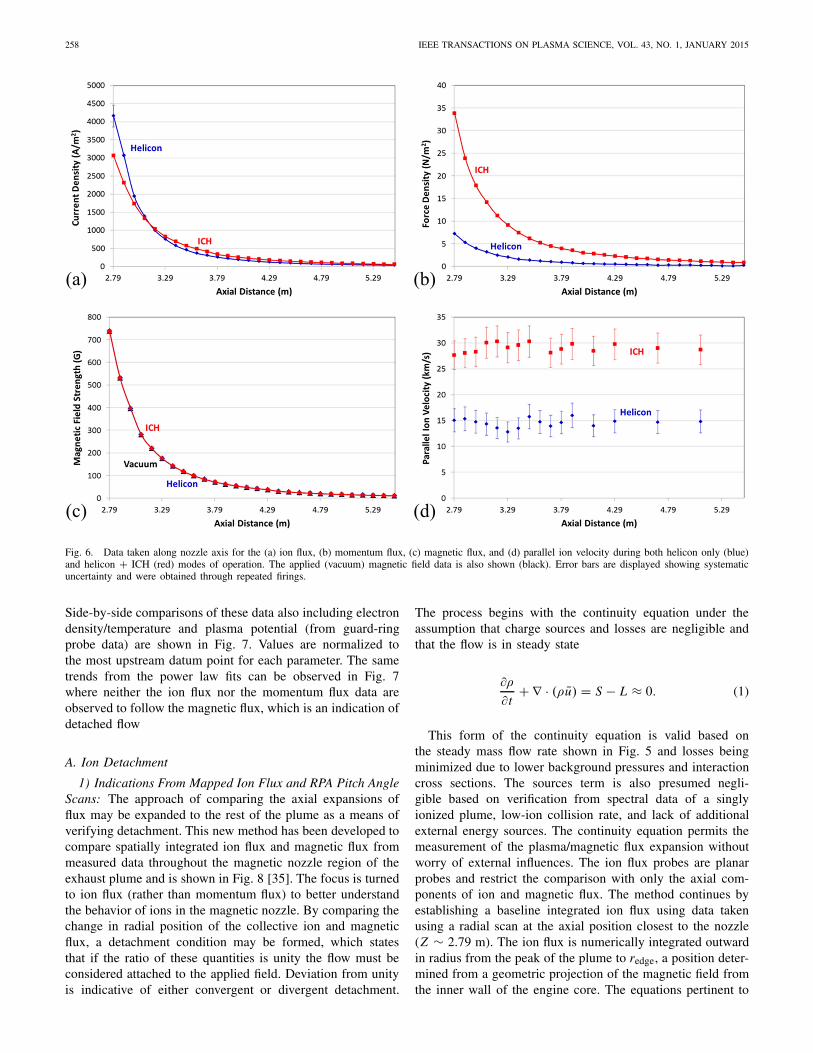
plasma detachment, there are two challenges that need to beresolved: 1) obtain evidence that detachment has occurred and2) verify if any currently accepted theories are applicable basedon the behavior of the flow. For the first challenge, a simplifiedview of the problem of actually measuring plasma detachmentis to see if the measured flow does not expand at the samerate at the magnetic field. An initial approach to quantifythis notion is to compare the expansion of certain plasmaparameters along the axis of the nozzle. Ion flux, momentumflux, magnetic flux, and parallel ion velocity data taken alongthe nozzle axis during both the helicon and helicon + ICHtime windows are shown in Fig. 6.
There are several significant observations regarding thetrends presented previously, the first of which is that thereis virtually no difference in the measured magnetic field whenthe plasma is flowing when compared the applied magneticfield; the largest difference is 0.2 G. The second notable itemis that there appears to be no additional acceleration or dragforces present as the parallel ion velocity is essentially flatindicating that the adiabatic conversion from perpendicular toparallel motion is complete. A final observation is that thereare two regions of expansion during both time windows forthe ion, momentum, and magnetic fluxes: 1) a fast expandingregion over the first �Z ∼ 0.6 m and 2) a more gradualexpansion region over the final �Z ∼ 2 m. It is usefulto compare the rates of expansion for each of the fluxes.Exponential fits were initially used, but it was later determinedthat a power law scaling yielded superior coefficients ofdetermination (>0.995). The best power law fits are displayedin Table II. These fits show, when comparing the falloffin concentration, that the plasma is not expanding with themagnetic field. Fits to the ion flux data show signs of divergentdetachment (expanding faster than the magnetic field) duringthe low-energy helicon operation and convergent detachmentduring ICH when the ion energy increases by a factor offour. The ion flux data during the helicon phase may beindicative of radial ambipolar forces causing the ions to expandfaster than the magnetic field and is overcome when the ionenergy is increased. Power law fits to the momentum fluxdata from the PMFS, which is sensitive to both ions andneutrals, shows only convergent detachment when comparedwith the magnetic field during both modes of operation. Theneutrals likely contribute a significant portion of the alreadyweak signal of the PMFS during helicon operation and givethe impression of convergent detachment. This proportionalcontribution is not the case during ICH as the much greaterimpact force of the ions dominates the much stronger signal.
258 IEEE TRANSACTIONS ON PLASMA SCIENCE, VOL. 43, NO. 1, JANUARY 2015
Fig. 6. Data taken along nozzle axis for the (a) ion flux, (b) momentum flux, (c) magnetic flux, and (d) parallel ion velocity during both helicon only (blue)and helicon + ICH (red) modes of operation. The applied (vacuum) magnetic field data is also shown (black). Error bars are displayed showing systematicuncertainty and were obtained through repeated firings.
Side-by-side comparisons of these data also including electrondensity/temperature and plasma potential (from guard-ringprobe data) are shown in Fig. 7. Values are normalized tothe most upstream datum point for each parameter. The sametrends from the power law fits can be observed in Fig. 7where neither the ion flux nor the momentum flux data areobserved to follow the magnetic flux, which is an indication ofdetached flow
A. Ion Detachment
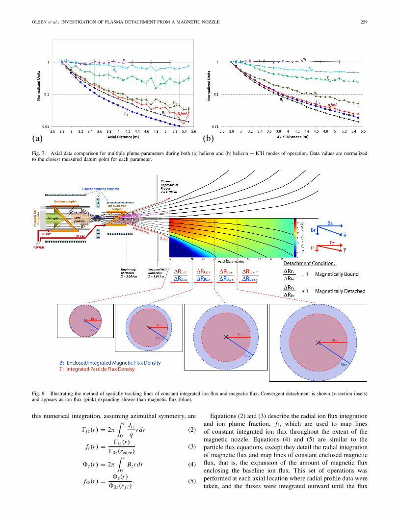
1) Indications From Mapped Ion Flux and RPA Pitch AngleScans: The approach of comparing the axial expansions offlux may be expanded to the rest of the plume as a means ofverifying detachment. This new method has been developed tocompare spatially integrated ion flux and magnetic flux frommeasured data throughout the magnetic nozzle region of theexhaust plume and is shown in Fig. 8 [35]. The focus is turnedto ion flux (rather than momentum flux) to better understandthe behavior of ions in the magnetic nozzle. By comparing thechange in radial position of the collective ion and magneticflux, a detachment condition may be formed, which statesthat if the ratio of these quantities is unity the flow must beconsidered attached to the applied field. Deviation from unityis indicative of either convergent or divergent detachment.
The process begins with the continuity equation under theassumption that charge sources and losses are negligible andthat the flow is in steady state
∂ρ
∂ t+ ∇ · (ρu) = S − L ≈ 0. (1)
This form of the continuity equation is valid based onthe steady mass flow rate shown in Fig. 5 and losses beingminimized due to lower background pressures and interactioncross sections. The sources term is also presumed negli-gible based on verification from spectral data of a singlyionized plume, low-ion collision rate, and lack of additionalexternal energy sources. The continuity equation permits themeasurement of the plasma/magnetic flux expansion withoutworry of external influences. The ion flux probes are planarprobes and restrict the comparison with only the axial com-ponents of ion and magnetic flux. The method continues byestablishing a baseline integrated ion flux using data takenusing a radial scan at the axial position closest to the nozzle(Z ∼ 2.79 m). The ion flux is numerically integrated outwardin radius from the peak of the plume to redge, a position deter-mined from a geometric projection of the magnetic field fromthe inner wall of the engine core. The equations pertinent to
OLSEN et al.: INVESTIGATION OF PLASMA DETACHMENT FROM A MAGNETIC NOZZLE 259
Fig. 7. Axial data comparison for multiple plume parameters during both (a) helicon and (b) helicon + ICH modes of operation. Data values are normalizedto the closest measured datum point for each parameter.
Fig. 8. Illustrating the method of spatially tracking lines of constant integrated ion flux and magnetic flux. Convergent detachment is shown (x-section insets)and appears as ion flux (pink) expanding slower than magnetic flux (blue).
this numerical integration, assuming azimuthal symmetry, are
iz (r) = 2π∫ r
0
Jiz
qrdr (2)
fi (r) = iz(r)
0z(redge)(3)
z(r) = 2π∫ r
0Bzrdr (4)
f(r) = z(r)
0z(r f i ). (5)
Equations (2) and (3) describe the radial ion flux integrationand ion plume fraction, fi , which are used to map linesof constant integrated ion flux throughout the extent of themagnetic nozzle. Equations (4) and (5) are similar to theparticle flux equations, except they detail the radial integrationof magnetic flux and map lines of constant enclosed magneticflux, that is, the expansion of the amount of magnetic fluxenclosing the baseline ion flux. This set of operations wasperformed at each axial location where radial profile data weretaken, and the fluxes were integrated outward until the flux
260 IEEE TRANSACTIONS ON PLASMA SCIENCE, VOL. 43, NO. 1, JANUARY 2015
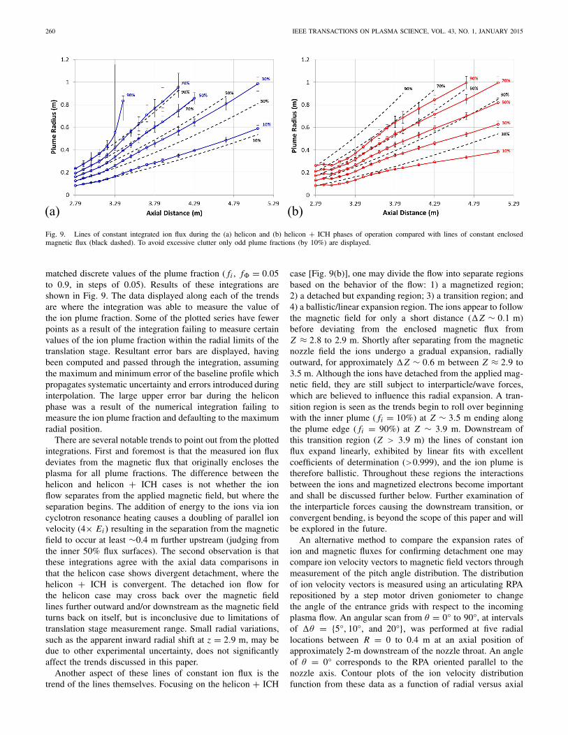
Fig. 9. Lines of constant integrated ion flux during the (a) helicon and (b) helicon + ICH phases of operation compared with lines of constant enclosedmagnetic flux (black dashed). To avoid excessive clutter only odd plume fractions (by 10%) are displayed.
matched discrete values of the plume fraction ( fi , f = 0.05to 0.9, in steps of 0.05). Results of these integrations areshown in Fig. 9. The data displayed along each of the trendsare where the integration was able to measure the value ofthe ion plume fraction. Some of the plotted series have fewerpoints as a result of the integration failing to measure certainvalues of the ion plume fraction within the radial limits of thetranslation stage. Resultant error bars are displayed, havingbeen computed and passed through the integration, assumingthe maximum and minimum error of the baseline profile whichpropagates systematic uncertainty and errors introduced duringinterpolation. The large upper error bar during the heliconphase was a result of the numerical integration failing tomeasure the ion plume fraction and defaulting to the maximumradial position.
There are several notable trends to point out from the plottedintegrations. First and foremost is that the measured ion fluxdeviates from the magnetic flux that originally encloses theplasma for all plume fractions. The difference between thehelicon and helicon + ICH cases is not whether the ionflow separates from the applied magnetic field, but where theseparation begins. The addition of energy to the ions via ioncyclotron resonance heating causes a doubling of parallel ionvelocity (4× Ei ) resulting in the separation from the magneticfield to occur at least ∼0.4 m further upstream (judging fromthe inner 50% flux surfaces). The second observation is thatthese integrations agree with the axial data comparisons inthat the helicon case shows divergent detachment, where thehelicon + ICH is convergent. The detached ion flow forthe helicon case may cross back over the magnetic fieldlines further outward and/or downstream as the magnetic fieldturns back on itself, but is inconclusive due to limitations oftranslation stage measurement range. Small radial variations,such as the apparent inward radial shift at z = 2.9 m, may bedue to other experimental uncertainty, does not significantlyaffect the trends discussed in this paper.
Another aspect of these lines of constant ion flux is thetrend of the lines themselves. Focusing on the helicon + ICH
case [Fig. 9(b)], one may divide the flow into separate regionsbased on the behavior of the flow: 1) a magnetized region;2) a detached but expanding region; 3) a transition region; and4) a ballistic/linear expansion region. The ions appear to followthe magnetic field for only a short distance (�Z ∼ 0.1 m)before deviating from the enclosed magnetic flux fromZ ≈ 2.8 to 2.9 m. Shortly after separating from the magneticnozzle field the ions undergo a gradual expansion, radiallyoutward, for approximately �Z ∼ 0.6 m between Z ≈ 2.9 to3.5 m. Although the ions have detached from the applied mag-netic field, they are still subject to interparticle/wave forces,which are believed to influence this radial expansion. A tran-sition region is seen as the trends begin to roll over beginningwith the inner plume ( fi = 10%) at Z ∼ 3.5 m ending alongthe plume edge ( fi = 90%) at Z ∼ 3.9 m. Downstream ofthis transition region (Z > 3.9 m) the lines of constant ionflux expand linearly, exhibited by linear fits with excellentcoefficients of determination (>0.999), and the ion plume istherefore ballistic. Throughout these regions the interactionsbetween the ions and magnetized electrons become importantand shall be discussed further below. Further examination ofthe interparticle forces causing the downstream transition, orconvergent bending, is beyond the scope of this paper and willbe explored in the future.
An alternative method to compare the expansion rates ofion and magnetic fluxes for confirming detachment one maycompare ion velocity vectors to magnetic field vectors throughmeasurement of the pitch angle distribution. The distributionof ion velocity vectors is measured using an articulating RPArepositioned by a step motor driven goniometer to changethe angle of the entrance grids with respect to the incomingplasma flow. An angular scan from θ = 0° to 90°, at intervalsof �θ = {5°, 10°, and 20°}, was performed at five radiallocations between R = 0 to 0.4 m at an axial position ofapproximately 2-m downstream of the nozzle throat. An angleof θ = 0° corresponds to the RPA oriented parallel to thenozzle axis. Contour plots of the ion velocity distributionfunction from these data as a function of radial versus axial
OLSEN et al.: INVESTIGATION OF PLASMA DETACHMENT FROM A MAGNETIC NOZZLE 261
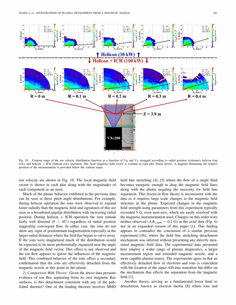
Fig. 10. Contour maps of the ion velocity distribution function as a function of VR and VZ arranged according to radial position (columns), helicon (toprow), and helicon + ICH (bottom row) operation. The local magnetic field vector is overlain in each plot (black arrow). A diagram illustrating the relativeposition of the measurements is provided below the contour maps.
ion velocity are shown in Fig. 10. The local magnetic fieldvector is shown in each plot along with the magnitudes ofeach component as an inset.
Much of the plume behavior exhibited in the previous datacan be seen in these pitch angle distributions. For example,during helicon operation the ions were observed to expandfaster radially than the magnetic field and signatures of this areseen as a broadened angular distribution with increasing radialposition. During helicon + ICH operation the ions remainfairly well directed (θ < 45°) regardless of radial positionsuggesting convergent flow. In either case, the ions do notshow any signs of predominant magnetization especially at thelarger radial distances where the field has begun to curve away.If the ions were magnetized much of the distribution wouldbe expected to be more preferentially organized near the angleof the magnetic field vector. This effect is not observed andthe ion flow appears to ignore the influences of the magneticfield. This combined behavior of the ions offers a secondaryconfirmation that the ions are effectively detached from themagnetic nozzle at this point in the plume.
2) Comparison With Theory: Given the above data presentsevidence of ion flux separating from its own magnetic fluxsurfaces, is this detachment consistent with any of the pub-lished theories? One of the leading theories involves MHD
field line stretching [4], [5] where the flow of a single fluidbecomes energetic enough to drag the magnetic field linesalong with the plume negating the necessity for field lineseparation. This frozen-in flow theory is inconsistent with thedata as it requires large scale changes to the magnetic fieldstructure in the plume. Expected changes in the magneticfield strength using parameters from this experiment typicallyexceeded 5 G, even near-axis, which are easily resolved withthe magnetic instrumentation used. Changes on this order wereneither observed (�Bz,max ∼ 0.2 G) in the axial data (Fig. 6)nor in an expanded version of this paper [1]. This findingappears to contradict the conclusion of a similar previousexperiment [36], where the field line stretching detachmentmechanism was inferred without presenting any directly mea-sured magnetic field data. The experimental data presentedhere employ a wider range of plasma diagnostics, a largermeasurement region and extended magnetic nozzle, and amore capable plasma source. The experiments agree in that aneffectively detached flow of electrons and ions is coincidentwith the location of the super-Alfvénic transition but differ onthe mechanism that effects the separation from the magneticfield [1].
Another theory, serving as a fundamental lower limit todetachment, known as electron inertia [8] where ions and
262 IEEE TRANSACTIONS ON PLASMA SCIENCE, VOL. 43, NO. 1, JANUARY 2015
electrons are electrostatically bound only drifting across themagnetic field lines if certain conditions are met. A governingparameter in this electron inertia theory is a scaling parame-ter, G, that involves the cyclotron frequencies as well as theplume radius and velocity at the nozzle throat and it is statedthat smaller values of G are more favorable for detachment[8]. The scaling parameter values for this experiment are4.3×106 and 1.1×10⁶ for plasma during helicon and helicon+ ICH, respectively. Accordingly, <1% of the plume should beseparating within the premise of this theory, which is not thecase (Fig. 9). Electron inertia may find more applicability uponconsidering additional effects found in essentially all plasmas.Ahedo and Merino [37] have shown this theory to be formallywrong and the data from this paper gives experimental supportto that claim.
The theory most consistent with the ion detachment datapresented above is a loss of adiabaticity [6], [7], [38]. Thistheory is essentially one of demagnetization where the ionsare unable to change gyro-motion parameters on the samescale as the diverging magnetic field. The diverging nozzlefield enables perpendicular to parallel ion velocity vectorconversion when the magnetic moment, μ, is conserved. Themagnetic moment is conserved so long as the action integral inFaraday’s law remains valid and breaks down when the particlegyro-orbit becomes too eccentric. An equation illustrating thismagnetic moment breakdown is [6]
�rLi
rLi≈ ��i
�i= vi
fci
|∇B|B
. (6)
This states that the magnetic moment will no longer be con-served when the change in Larmor radius becomes comparablewith itself, or when the ratio of the Larmor radius to magneticfield scale length (L B ∼ B/|∇B |) is of order unity. Along theregion where the lines of constant ion flux begin to divergefrom the magnetic flux in Fig. 9, the right hand side of (6) hasa range of 1.6–4.3 and 2.2–4.9 for the helicon and helicon +ICH phases, respectively. These ranges are both of order unity,are consistent in magnitude across each detachment zone, andshow agreement between ion flux probe data with magnetome-ter/RPA data. Recent simulations have been presented showingions detaching upon demagnetization and give support to thisdata [39]. Ion detachment via loss of adiabaticity is entirelyplausible if not considered confirmed altogether.
B. Electron Cross-Field Transport
Up to this point most of the focus has been on the dynamicsof the ions in the flow. Electrons, unlike the ions, are presumedto still be magnetized as the right hand side of (6) is stilla few orders of magnitude below unity (<0.013) over theentire measurement range of this experiment. Therefore, inthe scenario that the ions have become demagnetized electronsmust find a means of crossing the magnetic field lines, untilthey also become nonmagnetized, otherwise large scale elec-tric fields may arise as space-charge limits become unbalanced.The latter is not occurring given that the plasma potential datafrom Fig. 7 show no large transitions indicating only moderatedc electric fields. There is also the possibility that counter-streaming electrons forming localized longitudinal currents
may form mitigating these effects, but key signatures of thesecurrents were looked for but not seen [1]. This conclusiononly leaves the possibility that magnetized electrons will eithercause drag forces to arise on the ions, be impelled to crossthe field lines in the wake of the ions, or both to some degree.In the case of electrons crossing the field lines in pursuit ofthe ions, it must be required that they do so at approximatelythe same velocity as the ions to preserve quasi-neutrality. Itis then necessary to look for signatures of cross-field electrontransport across the measurement region.
1) Coulomb Collisions: One of the more straight forwardmechanisms for electrons to cross magnetic field lines isthrough collisions. Estimation of the classical collision fre-quency was done using the test particle model for electronsand singly charged ions [40]
ναβ(V ) = nβq4 ln
2πε20m2
αV 3[φ(aβV )− ψ(aβV )] (7)
aβ =√
mβ
2kB Tβ(8)
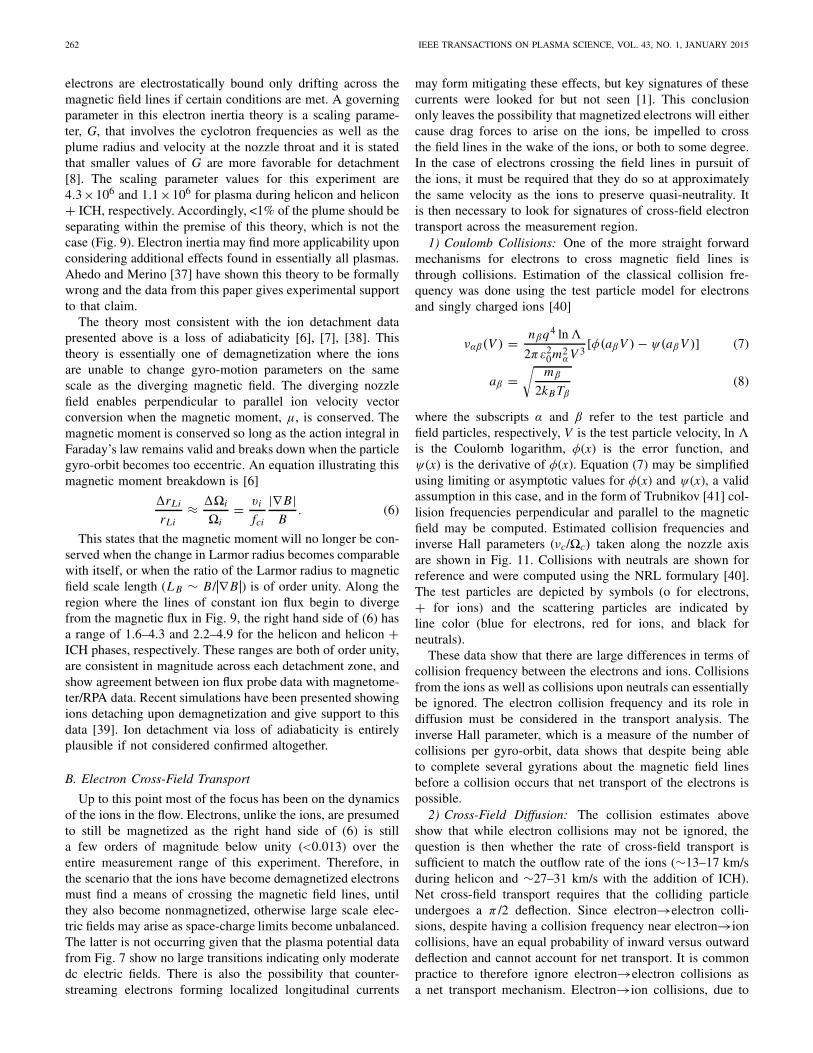
where the subscripts α and β refer to the test particle andfield particles, respectively, V is the test particle velocity, ln is the Coulomb logarithm, φ(x) is the error function, andψ(x) is the derivative of φ(x). Equation (7) may be simplifiedusing limiting or asymptotic values for φ(x) and ψ(x), a validassumption in this case, and in the form of Trubnikov [41] col-lision frequencies perpendicular and parallel to the magneticfield may be computed. Estimated collision frequencies andinverse Hall parameters (νc/�c) taken along the nozzle axisare shown in Fig. 11. Collisions with neutrals are shown forreference and were computed using the NRL formulary [40].The test particles are depicted by symbols (o for electrons,+ for ions) and the scattering particles are indicated byline color (blue for electrons, red for ions, and black forneutrals).
These data show that there are large differences in terms ofcollision frequency between the electrons and ions. Collisionsfrom the ions as well as collisions upon neutrals can essentiallybe ignored. The electron collision frequency and its role indiffusion must be considered in the transport analysis. Theinverse Hall parameter, which is a measure of the number ofcollisions per gyro-orbit, data shows that despite being ableto complete several gyrations about the magnetic field linesbefore a collision occurs that net transport of the electrons ispossible.
2) Cross-Field Diffusion: The collision estimates aboveshow that while electron collisions may not be ignored, thequestion is then whether the rate of cross-field transport issufficient to match the outflow rate of the ions (∼13–17 km/sduring helicon and ∼27–31 km/s with the addition of ICH).Net cross-field transport requires that the colliding particleundergoes a π /2 deflection. Since electron→electron colli-sions, despite having a collision frequency near electron→ioncollisions, have an equal probability of inward versus outwarddeflection and cannot account for net transport. It is commonpractice to therefore ignore electron→electron collisions asa net transport mechanism. Electron→ion collisions, due to
OLSEN et al.: INVESTIGATION OF PLASMA DETACHMENT FROM A MAGNETIC NOZZLE 263
Fig. 11. Collision frequency and inverse Hall parameter data along the nozzle axis during (a) and (c) helicon and (b) and (d) helicon + ICH operation. Testparticles are represented by symbols (o electron, + ion) while line color indicates the scatterer (blue–electrons, red–ions, and black–neutrals).
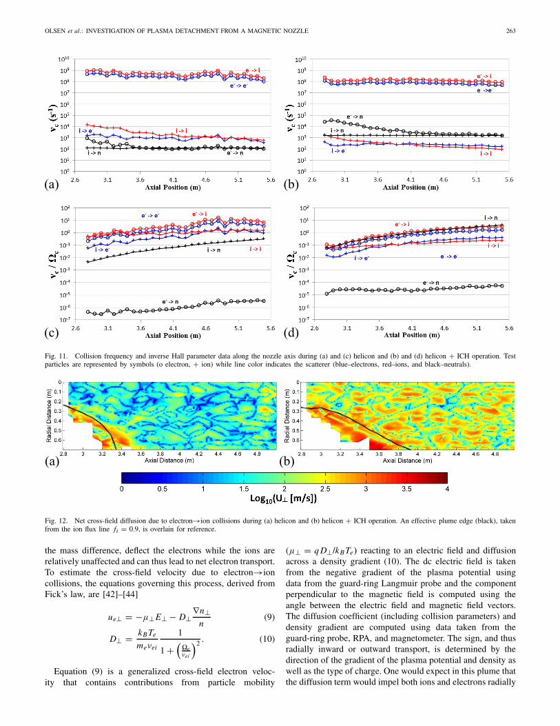
Fig. 12. Net cross-field diffusion due to electron→ion collisions during (a) helicon and (b) helicon + ICH operation. An effective plume edge (black), takenfrom the ion flux line fi = 0.9, is overlain for reference.
the mass difference, deflect the electrons while the ions arerelatively unaffected and can thus lead to net electron transport.To estimate the cross-field velocity due to electron→ioncollisions, the equations governing this process, derived fromFick’s law, are [42]–[44]
ue⊥ = −μ⊥E⊥ − D⊥∇n⊥
n(9)
D⊥ = kB Te
meνei
1
1 +(�eνei
)2 . (10)
Equation (9) is a generalized cross-field electron veloc-ity that contains contributions from particle mobility
(μ⊥ = q D⊥/kB Te) reacting to an electric field and diffusionacross a density gradient (10). The dc electric field is takenfrom the negative gradient of the plasma potential usingdata from the guard-ring Langmuir probe and the componentperpendicular to the magnetic field is computed using theangle between the electric field and magnetic field vectors.The diffusion coefficient (including collision parameters) anddensity gradient are computed using data taken from theguard-ring probe, RPA, and magnetometer. The sign, and thusradially inward or outward transport, is determined by thedirection of the gradient of the plasma potential and density aswell as the type of charge. One would expect in this plume thatthe diffusion term would impel both ions and electrons radially
264 IEEE TRANSACTIONS ON PLASMA SCIENCE, VOL. 43, NO. 1, JANUARY 2015
outward, while the mobility term would move the electronsinward and the ions outward. In the case of electron transport,the question is then which contribution is more dominanthaving the greater magnitude?
The net perpendicular cross-field velocity of electrons dueto electron→ion collisions has been computed using mappedquantities and is shown in Fig. 12. Although the figures appearnoisy, common as taking gradients accentuates noise in data,valuable trends still emerge. The largest cross-field velocitiesare seen along the plume edges (outside the black lines) wherethe density gradient is largest and the diffusion contributiondominates. Inside of the plume (< fi = 0.9) it is found that themobility contribution, enabling inward transport of electrons,is greater due to dc electric fields within the plasma. Outside ofthe plume (> fi = 0.9) the density gradient largely dominatescausing radially outward transport of electrons. A map ofeach computed contribution to the net electron transport ispresented in a separate work [1]. Nonetheless, electron→ioncollisions cannot alone account for the velocities needed tomatch the ions as they are insufficient by at least an order ofmagnitude. Additional processes must be occurring to facilitatethe detachment process.
3) Anomalous Transport: Anomalous resistivity has beenmentioned as a possible mechanism to enhance cross-fieldparticle transport in the detachment process [8], [9], [18], [45].It is described as a means to increase the effective col-lision rate above interparticle collisions, up to the Bohmlimit (DBohm = T /B), through interactions between particlesand a high frequency wave (e.g., oscillating electric field).The waves are introduced through turbulence as the plasmaresponds to perturbing instabilities. The modified two-streaminstability has been mentioned as viable candidate [33] incurved magnetic fields as the ions and magnetized electronsdrift apart, with particular interest in frequencies near the lowerhybrid where both particles responses are maximized [i.e.,lower hybrid drift instability (LHDI)]. As a result of theseinstabilities it has been found that the fluctuations in densityand electric field are in phase [45] and creates an effectiveresistivity above the collisional value [33]
ηeff = ηc + ηAN ≈ ηc + 〈ne E〉qude〈ne〉2 (11)
where the tilde denotes fluctuating quantities, ‹› representsthe time average of enclosed parameters, and ude is driftvelocity of the electron beam relative to the ion beam.The contribution from anomalous resistivity (ηAN) wouldnormally include oscillating magnetic field components [46],but are presumed negligible compared with the electric field.It is left as future work to measure the high-frequency compo-nents of the magnetic field and its role in anomalous transport.The effective resistivity modifies the perpendicular diffusioncoefficient (and likewise electron mobility) to [47]
D⊥ = kB Te
q B
(�eτeff
1 + (�eτeff)2
)(12)
τeff = me
ηeff q2ne. (13)
The effective momentum transfer time, τeff , is the timeinterval for momentum exchanges between the electrons and
fluctuating electric field and is the inverse of the effectivecollision frequency.
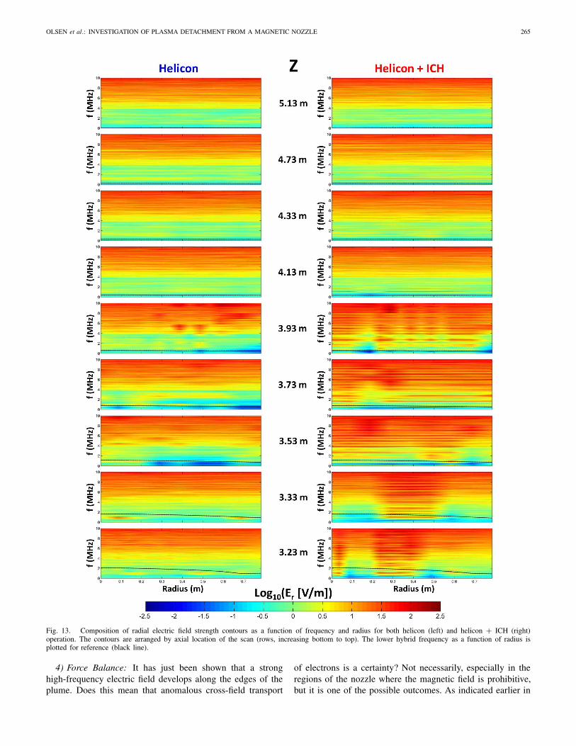
If anomalous transport were to be applicable in this setup,signatures of a high-frequency electric field, particularly nearthe lower hybrid frequency, should arise throughout the regionsof the nozzle where ions have deviated from the magnetic field.The high-frequency electric field probe was used to explorethese effects. Due to the orientation of the probes’ electrodes,only the radial component of the electric field (Er ) was mea-sured searching frequencies up to 10 MHz. Recalling that theprobe was located ∼33-cm downstream the other diagnostics,due to material thermal limitations, the regions indicating ionseparation were unable to be measured. Nevertheless studyinghigh-frequency phenomena in the expanding, transition, andballistic regions as parsed by the ion flux data is valuable.Spectra have been taken and mapped out as a function of radialposition at discreet axial locations for both phases of VX-200 operation and are shown in Fig. 13. Each contour plot iscomprised of the logarithmic value of the radial electric field asa function of frequency and radius and arranged by increasingZ position from bottom to top. A thin black line marks thelower hybrid frequency ( fLH) as a function of radial position.
There appears to be an overall trend of increasing radialelectric field strength at higher frequencies, likely buildingto a resonance, both in and out of the plasma flow. It isyet to be determined if this effect is dependent upon theprobe/electronics or perhaps a result of the chamber/tuningcavity environment, which is beyond the scope of this paper.Despite this behavior any local variations in the radial electricfield should be apparent as the majority of the peaks in thistrend to resonance are below 90 V/m for frequencies up to9.5 MHz, which is far below the electric field magnitudesexpected to enable anomalous transport.
Unique to the case of hotter ions (during helicon + ICH)is a distinct structure or grouping of electric field peaks thatforms near the edge of the flow coincident with regions oflower magnetic field radial curvature. This observation issignificant since the lower curvature may provide a greaterdivergence of the electrons from the detached ions allowingthe instability to form. The greatest amplitude Er along theedge of the flow was 740 V/m at a frequency of 5.51 MHz,which is approximately ∼3f LH suggesting the LHDI maybe involved. This edge structure spreads out and dissipateswith increasing axial distance before disappearing altogetherbeyond Z > 3.93 m. The locations where this Er structurespreads to the interior of the plume line up well with theion flux transition region where the flow linearizes between3.5 m < Z < 3.9 m in Fig. 9. The vanishing of the structurealtogether in the weaker magnetic field correlates well with theion flux ballistic/linear region Z > 3.9 m in Fig. 9, indicatingthe instability is no longer active, electron/ion separation hasminimized, and the flow has effectively detached from themagnetic nozzle. The structure is not readily observed duringphases of operating the helicon source alone, which eitherdoes not exist or was not measured far enough radially. Itis left as future work to explore electric and magnetic fieldphenomena at higher frequencies, at greater radii, and alongmultiple vector components.
OLSEN et al.: INVESTIGATION OF PLASMA DETACHMENT FROM A MAGNETIC NOZZLE 265
Fig. 13. Composition of radial electric field strength contours as a function of frequency and radius for both helicon (left) and helicon + ICH (right)operation. The contours are arranged by axial location of the scan (rows, increasing bottom to top). The lower hybrid frequency as a function of radius isplotted for reference (black line).
4) Force Balance: It has just been shown that a stronghigh-frequency electric field develops along the edges of theplume. Does this mean that anomalous cross-field transport
of electrons is a certainty? Not necessarily, especially in theregions of the nozzle where the magnetic field is prohibitive,but it is one of the possible outcomes. As indicated earlier in
266 IEEE TRANSACTIONS ON PLASMA SCIENCE, VOL. 43, NO. 1, JANUARY 2015
this section, the behavior of the flow will ultimately dependupon an electrostatic force balance between the ions andelectrons and how each respond to the fluctuating electricfields in the plume. The ion response to these fluctuatingfields will be to follow electrons along the magnetic field lineswhere the electric fields are large enough to balance or exceedthe centrifugal force on the ions, thus trapping them in themagnetic field
E⊥IonTrapping = miv2i
q Rc(14)
where Rc is the radius of curvature of the interacting magneticfield line. The electron response is to diffuse anomalouslyacross the outer magnetic field lines to follow the ballistic ionsalong more centrally located field lines. The enabling electricfield in this scenario is then the ratio of the cross-field electronvelocity to the anomalous mobility
E⊥Anomalous = u⊥μ⊥
= vi sin θB
(1 + (�eτeff )
2
�eτeff
). (15)
The cross-field electron velocity (u⊥) required to abatespace-charge buildup due to ions departing with velocity, vi ,is the product of the ion velocity and the sine of the separationangle of the ions and magnetic field line.
The balance of forces, an electrostatic tug-of-war, to deter-mine which process dominates between ion trapping andanomalous resistivity depends upon the localized microscaleconditions in the plume. The process requiring the lowerelectric field strength will saturate and never reach the fieldstrength necessary for the other process to operate. It shouldthen be expected that the ion trapping process will domi-nate (‹E⊥›Ion Trapping < ‹E⊥›Anomalous) in high-magnetic fieldregions, areas where the radius of curvature is large, and/or forlower ion mass and velocity. Conditions for anomalous resis-tivity to dominate (‹E⊥›Anomalous < ‹E⊥›Ion Trapping) wouldthen be for heavier or faster ions, lower magnetic fields,larger effective collision frequency, and/or lower radius ofcurvature.
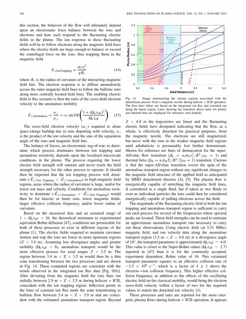
Based on the measured data and an assumed range of1 < �eτeff < 16, the theoretical minimum to experimentalequivalent Bohm diffusion [47], conditions are permissible forboth of these processes to exist in different regions of theplume [1]. The electric fields required to maintain curvaturemotion and trap the ions are lower in more upstream regions(Z < 3.4 m). Assuming low divergence angles and greatermobility (�eτeff < 6), anomalous transport would be themore effective process for axial ranges Z > 3.5 m. Theregion between 3.4 m < Z < 3.5 m would then be a thinzone transitioning between the two processes and are shownin Fig. 14. These computed regions are consistent with thetrends observed in the integrated ion flux data [Fig. 9(b)].After deviating from the magnetic field the ions flare outradially between 2.9 m < Z < 3.5 m during helicon + ICH,coincident with the ion trapping region. Inflection points inthe lines of constant ion flux mark the zone transitioning toballistic flow between 3.4 m < Z < 3.9 m and are coinci-dent with the estimated anomalous transport region. Beyond
Fig. 14. Image summarizing the various regions associated with thedetachment process from a magnetic nozzle during helicon + ICH operation.The flow lines (blue) are based on the integrated ion flux and extended outalong the linear region. Lines showing the transition above unity for kineticand thermal beta are displayed for reference (red dashed).
Z > 4.0 m the trajectories are linear and the fluctuatingelectric fields have dissipated indicating that the flow, as awhole, is effectively detached for practical purposes, fromthe magnetic nozzle. The electrons are still magnetized,but move with the ions in the weaker magnetic field regionsuntil adiabaticity is presumably lost further downstream.Shown for reference are lines of demarcation for the super-Alfvénic flow transition (βk = ni miv
2i /B2/μ0 = 1) and
thermal beta (βth = ni kB Ti/B2/2μ0 = 1) transition. Curiousis that the super-Alfvénic transition covers the span of theanomalous transport region without any significant changes tothe magnetic field structure of the applied field as anticipatedby MHD detachment theories [4], [5]. The plasma flow isenergetically capable of stretching the magnetic field lines,if considered as a single fluid, but if taken as two fluids oreven as individual particles the ions could then be consideredenergetically capable of pulling electrons across the field.
The magnitude of the fluctuating electric field in both the iontrapping and anomalous transport region is sufficient to carryout each process for several of the frequencies where spectralpeaks are located. These field strengths can be used to estimatean approximate anomalous transport rate necessary to carryout these observations. Using electric field (at 5.51 MHz),magnetic field, and ion velocity data along the anomaloustransport region (3.5 m < Z < 4.0 m) at a divergence angleof 10°, the transport parameter is approximately�eτeff ∼ 4.0.This value is closer to the Super-Bohm values (�eτeff ∼ 2.7)reported in [47] than it is for the commonly accepted,experiment dependent, Bohm value of 16. This estimatedtransport parameter equates to an effective collision rate of∼3.5 × 10⁸ s−1, which is a factor of 4 ± 1 above theelectron→ion collision frequency. This higher effective col-lision frequency, in addition to the effects of the oscillatingelectric field on the classical mobility, would bring the electroncross-field velocity within a factor of two for the requiredvalues to match the detached ion velocity [1].
These processes and rates are reported for the more ener-getic plasma flows during helicon + ICH operation. It appears
OLSEN et al.: INVESTIGATION OF PLASMA DETACHMENT FROM A MAGNETIC NOZZLE 267
that ion trapping or radial ambipolar forces dominate theplume behavior for lower ion velocity flow during helicononly operation. Although not directly observed, anomaloustransport may still be occurring in the weak magnetic fieldregions beyond the limits of the translation stage. It may bethe focus of future experiments to explore the plume furtherout in radius during plasma operation at lower ion energy.
IV. CONCLUSION
An experiment using the VASIMR VX-200 device operatingat a power level of 100 kW was carried out to map the behaviorof plasma flowing through a magnetic nozzle and to studythe detachment process. The plasma was not following theapplied magnetic field, indicated by data from multiple plasmadiagnostics. Key indications of detached flow were frommapped lines of constant integrated ions flux, an RPA pitchangle distribution, and a spatially dependent high frequencyelectric field. Plasma detachment is best described as a twopart process first involving the separation of the ion from themagnetic field through the breakdown of the ion magneticmoment. The second part involves turbulence, created by insta-bilities, where a fluctuating electric field facilitates competinginteractions between detached ion and magnetized electrons.In stronger magnetic field regions the electrons are moretightly bound to the field and the ion are temporarily trappedflaring outward as the field expands. As the magnetic fieldweakens the ion begin to dominate and the electrons respondto the turbulent electric field through enhanced anomaloustransport. The electrons cross the magnetic field lines pursuingthe ion until the turbulent electric field dissipates and the iontrajectories linearize resulting in an effectively detached plume∼2-m downstream of the nozzle throat.
Future work may include making the same measurementsout to greater radii, including new hardware to measure theaxial component of the high frequency electric field, andexplore for effects from a plausible high frequency magneticfield to better characterize anomalous transport rates in theplume. Also possible may be to explore the detachmentprocesses at various VASIMR power levels (i.e., multiple ionenergies), propellant flow rates, and propellant species.
REFERENCES
[1] C. S. Olsen, “Experimental characterization of plasma detachment frommagnetic nozzles,” Dept. Phys. Astronomy, Rice Univ., Houston, TX,USA, Tech. Rep. 1911/72016, 2013, p. 298.
[2] E. Ahedo, “Plasmas for space propulsion,” Plasma Phys. ControlledFusion, vol. 53, no. 12, p. 124037, 2011.
[3] R. A. Gerwin et al., “Characterization of plasma flow through magneticnozzles,” Los Alamos National Laboratory, Los Alamos, NM, USA,Tech. Rep. ADA221044, 1990, p. 173.
[4] A. V. Arefiev and B. N. Breizman, “Magnetohydrodynamic scenario ofplasma detachment in a magnetic nozzle,” Phys. Plasmas, vol. 12, no. 4,pp. 043504-1–043504-10, 2005.
[5] B. N. Breizman, M. R. Tushentsov, and A. V. Arefiev, “Magnetic nozzleand plasma detachment model for a steady-state flow,” Phys. Plasmas,vol. 15, no. 5, pp. 057103-1–057103-10, 2008.
[6] M. D. Carter et al., “Radio frequency plasma applications for spacepropulsion,” in Proc. Int. Conf. Electromagn. Adv. Appl., Turin, Italy,1999.
[7] K. Terasaka, S. Yoshimura, K. Ogiwara, M. Aramaki, and M. Y. Tanaka,“Experimental studies on ion acceleration and stream line detach-ment in a diverging magnetic field,” Phys. Plasmas, vol. 17, no. 7,pp. 072106-1–072106-6, 2010.
[8] E. B. Hooper, “Plasma detachment from a magnetic nozzle,” J. Propuls.Power, vol. 9, no. 5, pp. 757–763, 1993.
[9] E. Ahedo and M. Merino, “On plasma detachment in propulsive mag-netic nozzles,” Phys. Plasmas, vol. 18, no. 5, pp. 053504-1–053504-8,2011.
[10] E. Bering, B. Longmier, T. Glover, F. C. Diaz, J. Squire, andM. Brukardt, “High power electric propulsion using VASIMR: Resultsfrom flight prototypes,” in Proc. 47th AIAA Aerosp. Sci. Meeting andExhibit., Orlando, FL, USA, 2009.
[11] B. W. Longmier et al., “Improved efficiency and throttling range ofthe VX-200 magnetoplasma thruster,” J. Propuls. Power, vol. 30, no. 1,pp. 123–132, 2014.
[12] F. F. Chen and R. W. Boswell, “Helicons—The past decade,” IEEETrans. Plasma Sci., vol. 25, no. 6, pp. 1245–1257, Dec. 1997.
[13] R. W. Boswell and F. F. Chen, “Helicons—The early years,” IEEE Trans.Plasma Sci., vol. 25, no. 6, pp. 1229–1244, Dec. 1997.
[14] J. P. Squire et al., “VASIMR performance measurements at powersexceeding 50 kW and lunar robotic mission applications,” in Proc. Int.Interdiscipl. Symp. Gaseous and Liquid Plasmas, Sendai, Japan, 2008.
[15] L. D. Cassady et al., “VASIMR technological advances and firststage performance results,” in Proc. 45th AIAA/ASME/SAE/ASEE JointPropuls. Conf. Exhibit., 2009.
[16] B. W. Longmier et al., “VASIMR VX-200 performance measurementsand helicon throttle tables using argon and krypton,” in Proc. 32nd IEPC,2011.
[17] B. W. Longmier et al., “VASIMR VX-200 improved throttling range,”in Proc. 48th AIAA/ASME/SAE/ASEE Joint Propuls. Conf., 2012.
[18] A. V. Arefiev and B. N. Breizman, “Theoretical components of theVASIMR plasma propulsion concept,” Phys. Plasmas, vol. 11, no. 5,pp. 2942–2949, 2004.
[19] E. A. Bering et al., “Observations of single-pass ion cyclotron heat-ing in a trans-sonic flowing plasma,” Phys. Plasmas, vol. 17, no. 4,pp. 043509-1–043509-19, 2010.
[20] T. H. Stix, “Ion cyclotron heating of a plasma,” J. Nucl. Energy C,Plasma Phys., Accelerators, Thermonucl. Res., vol. 2, no. 1, p. 84, 1961.
[21] J. P. Squire et al., “Superconducting 200 kW VASIMR experiment andintegrated testing,” in Proc. 31st Int. Electric Propuls. Conf., 2009.
[22] W. Lochte-Holtgreven, “Plasma diagnostics,” in American Vacuum Soci-ety Classics, 2nd ed. New York, NY, USA: AIP Press, 1995, p. 928.
[23] B. W. Longmier et al., “Ambipolar ion acceleration in an expand-ing magnetic nozzle,” Plasma Sources Sci. Technol., vol. 20, no. 1,p. 015007, 2011.
[24] C. S. Olsen, “Ion flux maps and helicon source efficiency in the VASIMRVX-100 experiment using a moving langmuir probe array,” in Physicsand Astronomy. Houston, TX, USA: Rice Univ. Press, 2009, p. 155.
[25] D. G. Chavers and F. R. Chang-Diaz, “Momentum flux measuringinstrument for neutral and charged particle flows,” Rev. Sci. Instrum.,vol. 73, no. 10, pp. 3500–3507, 2002.
[26] X. Chen, “The impact force acting on a flat plate exposed normally toa rarefied plasma plume issuing from an annular or circular nozzle,”J. Phys. D, Appl. Phys., vol. 43, no. 31, p. 315205, 2010.
[27] D. G. Chavers, F. R. Chang-Díaz, C. Irvine, and J. P. Squire,“Momentum and heat flux measurements in the exhaust of VASIMRusing helium propellant,” in Proc. 28th Int. Electr. Propuls. Conf., 2003.
[28] B. W. Longmier et al., “Validating a plasma momentum flux sensor toan inverted pendulum thrust stand,” J. Propuls. Power, vol. 25, no. 3,pp. 746–752, 2009.
[29] L. W. Parker, “Theory of a satellite electrostatic probe,” Ann. Phys.,vol. 44, no. 1, pp. 126–161, 1967.
[30] E. A. Bering, K. G. Weber, and U. V. Fahleson, “An upper limit on theaperture separation of ion drift meters,” Astrophys. Space Sci., vol. 83,nos. 1–2, pp. 37–49, 1982.
[31] E. A. Bering, III, F. Chang-Diaz, and J. Squire, “The use of RF wavesin space propulsion systems,” 2004.
[32] T. Hurtig and J. Wistedt, “Probes for high-frequency measurements ina plasma gun,” Rev. Sci. Instrum., vol. 74, no. 2, pp. 1153–1155, 2003.
[33] T. Hurtig, N. Brenning, and M. A. Raadu, “The role of high fre-quency oscillations in the penetration of plasma clouds across magneticboundaries,” Phys. Plasmas, vol. 12, no. 1, pp. 012308-1–012308-13,2005.
[34] J. S. Bendat and A. G. Piersol, “Random data analysis and measurementprocedures,” Meas. Sci. Technol., vol. 11, no. 12, p. 1825, 2000.
[35] J. P. Squire et al., “VASIMR VX-200 operation at 200 kW and plumemeasurements: Future plasma and an ISS EP test platform,” in Proc.32nd IEPC, 2011.
[36] C. A. Deline et al., “Plume detachment from a magnetic nozzle,” Phys.Plasmas, vol. 16, no. 3, pp. 033502-1–033502-9, 2009.
268 IEEE TRANSACTIONS ON PLASMA SCIENCE, VOL. 43, NO. 1, JANUARY 2015
[37] E. Ahedo and M. Merino, “Two-dimensional plasma expansion in amagnetic nozzle: Separation due to electron inertia,” Phys. Plasmas,vol. 19, no. 8, pp. 083501-1–083501-9, 2012.
[38] K. Terasaka, S. Yoshimura, K. Ogiwara, M. Aramaki, and M. Y. Tanaka,“Observation of ion stream line detachment and onset of azimuthalrotation in a diverging magnetic field,” IEEE Trans. Plasma Sci., vol. 39,no. 11, pp. 2470–2471, Nov. 2011.
[39] M. Merino and E. Ahedo, “Magnetic nozzle far-field simulation,” inProc. 48th AIAA/ASME/SAE/ASEE Joint Propuls. Conf. Exhibit., 2012.
[40] J. D. Huba, NRL Plasma Formulary. Washington, DC, USA: The Officeof Naval Research, 2012.
[41] B. A. Trubnikov, “Particle interactions in a fully ionized plasma,” inReviews of Plasma Physics, vol. 1. New York, NY, USA: ConsultantsBureau, 1965, p. 105.
[42] M. A. Lieberman and A. J. Lichtenberg, Principles of Plasma Dis-charges and Materials Processing, 2nd ed. Hoboken, NJ, USA: Wiley,2005, p. 757.
[43] F. F. Chen, “Introduction to plasma physics and controlled fusion,” inPlasma Physics, vol. 1, 2nd ed. New York, NY, USA: Plenum Press,1984, p. 421.
[44] D. M. Goebel and I. Katz, “Basic plasma physics,” in Fundamentals ofElectric Propulsion. New York, NY, USA: Wiley, 2008, pp. 37–90.
[45] N. Brenning, T. Hurtig, and M. A. Raadu, “Conditions for plasmoidpenetration across abrupt magnetic barriers,” Phys. Plasmas, vol. 12,no. 1, pp. 012309-1–012309-10, 2005.
[46] E. Y. Choueiri, “Anomalous resistivity and heating in current-drivenplasma thrusters,” Phys. Plasmas, vol. 6, no. 5, pp. 2290–2306, 1999.
[47] N. Brenning, R. L. Merlino, D. Lundin, M. A. Raadu, andU. Helmersson, “Faster-than-Bohm Cross-B electron transport instrongly pulsed plasmas,” Phys. Rev. Lett., vol. 103, no. 22,pp. 225003-1–225003-4, 2009.
Authors’ photographs and biographies not available at the time of publication.