2300-20 and 2300-25 vibration monitors datasheet - 105m0340 · the 2300 vibration monitors deliver...
TRANSCRIPT

DescriptionThe 2300 Vibration Monitors provide cost-effective continuous vibration monitoring and protection capabilities for less critical and spared machinery. They are specifically designed to continuously monitor and protect essential medium to low criticality machinery in a wide range of industries including: oil & gas, power generation, water treatment, pulp and paper, manufacturing, mining, cement, and other industries.
The 2300 Vibration Monitors deliver vibration monitoring and high vibration level alarming. They include two channels of seismic or proximity measurement inputs from various accelerometer, Velomitor and Proximitor types, a speed input channel for time-synchronous measurements, and outputs for relay contacts. The 2300/20 monitor features a configurable 4-20 mA output which interfaces more points to a DCS. The 2300/25 monitor features System 1connectivity for Trendmaster SPA interface which enables users to leverage existing DSM SPA infrastructure.
The 2300 Vibration Monitors are designed for use on a broad range of machine trains or individual casings where the sensor point count fits the monitor’s channel count and where advanced signal processing is desired.
Document: 105M0340Rev. R
2300/20 and 2300/25 Vibration MonitorsDatasheetBently Nevada Machinery Condition Monitoring
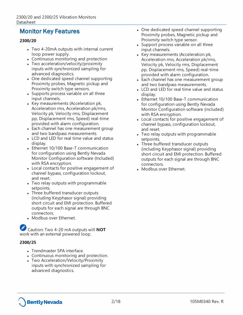
Monitor Key Features2300/20
l Two 4-20mA outputs with internal current loop power supply.
l Continuous monitoring and protection l Two acceleration/velocity/proximity
inputs with synchronized sampling for advanced diagnostics.
l One dedicated speed channel supporting Proximity probes, Magnetic pickup and Proximity switch type sensors.
l Supports process variable on all three input channels.
l Key measurements (Acceleration pk, Acceleration rms, Acceleration pk/rms, Velocity pk, Velocity rms, Displacement pp, Displacement rms, Speed) real-time provided with alarm configuration.
l Each channel has one measurement group and two bandpass measurements.
l LCD and LED for real time value and status display.
l Ethernet 10/100 Base-T communication for configuration using Bently Nevada Monitor Configuration software (Included) with RSA encryption.
l Local contacts for positive engagement of channel bypass, configuration lockout, and reset.
l Two relay outputs with programmable setpoints.
l Three buffered transducer outputs (including Keyphasor signal) providing short circuit and EMI protection. Buffered outputs for each signal are through BNC connectors.
l Modbus over Ethernet.
Caution: Two 4-20 mA outputs will NOT work with an external powered loop.
2300/25
l Trendmaster SPA interface. l Continuous monitoring and protection. l Two Acceleration/Velocity/Proximity
inputs with synchronized sampling for advanced diagnostics.
l One dedicated speed channel supporting Proximity probes, Magnetic pickup and Proixmity switch type sensor.
l Support process variable on all three input channels.
l Key measurements (Acceleration pk, Acceleration rms, Acceleration pk/rms, Velocity pk, Velocity rms, Displacement pp, Displacement rms, Speed) real-time provided with alarm configuration.
l Each channel has one measurement group and two bandpass measurements.
l LCD and LED for real time value and status display.
l Ethernet 10/100 Base-T communication for configuration using Bently Nevada Monitor Configuration software (included) with RSA encryption.
l Local contacts for positive engagement of channel bypass, configuration lockout, and reset.
l Two relay outputs with programmable setpoints.
l Three buffered transducer outputs (including Keyphasor signal) providing short circuit and EMI protection. Buffered outputs for each signal are through BNC connectors.
l Modbus over Ethernet.
2300/20 and 2300/25 Vibration MonitorsDatasheet
2/18 105M0340 Rev. R
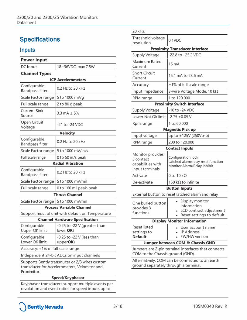
SpecificationsInputs
Power Input DC Input 18~36VDC, max 7.5WChannel Types
ICP Accelerometers Configurable Bandpass filter 0.2 Hz to 20 kHz
Scale Factor range 5 to 1000 mV/gFull scale range 2 to 80 g peakCurrent Sink Source 3.3 mA ± 5%
Open Circuit Voltage -21 to -24 VDC
Velocity Configurable Bandpass filter 0.2 Hz to 20 kHz
Scale Factor range 5 to 1000 mV/in/s Full scale range 0 to 50 in/s peak
Radial Vibration Configurable Bandpass filter 0.2 Hz to 20 kHz
Scale Factor range 5 to 1000 mV/milFull scale range 0 to 160 mil peak-peak
Thrust ChannelScale Factor range 5 to 1000 mV/mil
Process Variable ChannelSupport most of unit with default on Temperature
Channel Hardware SpecificationConfigurable Upper OK limit
-0.25 to -22 V (greater than lowerOK)
Configurable Lower OK limit
-0.25 to -22 V (less than upperOK)
Accuracy: +1% of full scale rangeIndependent 24-bit ADCs on input channelsSupports Bently transducer or 2/3 wires custom transducer for Accelerometers, Velomitor and Proximitor.
Speed/KeyphasorKeyphasor transducers support multiple events per revolution and event ratios for speed inputs up to
20 kHz.Threshold voltage resolution 0.1VDC
Proximity Transducer InterfaceSupply Voltage -22.8 to –25.2 VDCMaximum Rated Current 15 mA
Short Circuit Current 15.1 mA to 23.6 mA
Accuracy ±1% of full scale rangeInput Impedance 3-wire Voltage Mode, 10 kΩRPM range 1 to 120,000
Proximity Switch InterfaceSupply Voltage -10 to -24 VDCLower Not Ok limit -2.75 ±0.05 VRpm range 1 to 60,000
Magnetic Pick upInput voltage up to ±125V (250Vp-p)RPM range 200 to 120,000
Contact InputsMonitor provides 3 contact capabilities with input terminals
Configuration lockLatched alarm/relay reset functionMonitor Alarm/Relay Inhibit
Activate 0 to 10 kΩDe-activate 150 kΩ to infinite
Button InputsExternal button to reset latched alarm and relay
One buried button provides 3 functions
l Display monitor information
l LCD contrast adjustment l Reset settings to default
Display Monitor InformationReset listed settings to Default
l User account name l IP Address l FW/HW version
Jumper between COM & Chassis GNDJumpers are 2-pin terminal interfaces that connects COM to the Chassis ground (GND).Alternatively, COM can be connected to an earth ground separately through a terminal.
2300/20 and 2300/25 Vibration MonitorsDatasheet
3/18 105M0340 Rev. R
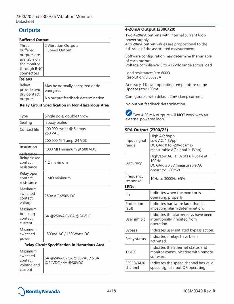
OutputsBuffered OutputThree buffered outputs are available on the monitor through BNC connectors
2 Vibration Outputs 1 Speed Output
RelaysRelays provide two dry-contact outputs
May be normally energized or de-energized
No output feedback determination
Relay Circuit Specification in Non-Hazardous Area
Type Single pole, double throw Sealing Epoxy sealed
Contact life 100,000 cycles @ 5 amps 250 VAC
200,000 @ 1 amp, 24 VDCInsulation
resistance 1000 MΩ minimum @ 500 VDC
Relay closed contact resistance
1 Ω maximum
Relay open contact resistance
1 MΩ minimum
Maximum switched contact voltage
250V AC /250V DC
Maximum breaking contact current
6A @250VAC / 6A @24VDC
Maximum switched power
1500VA AC / 150 Watts DC
Relay Circuit Specification in Hazardous AreaMaximum switched contact voltage and current
6A @24VAC / 5A @30VAC / 5.8A @24VDC / 4A @30VDC
4-20mA Output (2300/20)Two 4-20mA outputs with internal current loop power supply 4 to 20mA output values are proportional to the full-scale of the associated measurement.
Software configuration may determine the variable of each output.Voltage compliance: 0 to +12Vdc range across load
Load resistance: 0 to 600ΩResolution: 0.3662uA
Accuracy: 1% over operating temperature range Update rate: 100ms
Configurable with default 2mA clamp current.
No output feedback determination.
Two 4-20 mA outputs will NOT work with an external powered loop. SPA Output (2300/25)
Input signal range
High AC: 8Vpp Low AC: 1.6Vpp DC GAP: 0 to -20Vdc (max measurable AC signal is 1Vpp).
Accuracy
High/Low AC: ±1% of Full-Scale at 100Hz DC GAP: ±0.5V (measurable AC accuracy: ±20mV)
Frequency response 10Hz to 3000Hz ±5%
LEDs
OK Indicates when the monitor is operating properly.
Protection fault
Indicates hardware fault that is impacting alarm determination.
User inhibit Indicates the alarm/relays have been intentionally inhibited from operation.
Bypass Indicates user initiated bypass action.
Relay status Indicates if relays have been activated.
TX/RXIndicates the Ethernet status and monitor communicating with remote software.
SPEED/AUX channel
Indicates the speed channel has valid speed signal input OR operating
2300/20 and 2300/25 Vibration MonitorsDatasheet
4/18 105M0340 Rev. R
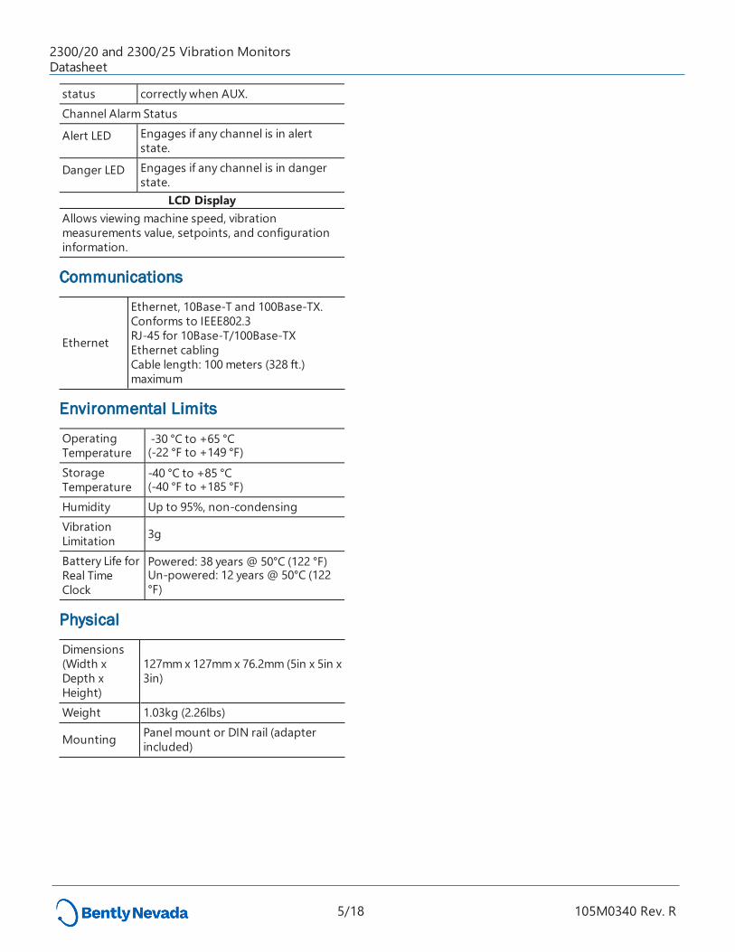
status correctly when AUX.Channel Alarm Status
Alert LED Engages if any channel is in alert state.
Danger LED Engages if any channel is in danger state.
LCD DisplayAllows viewing machine speed, vibration measurements value, setpoints, and configuration information.
Communications
Ethernet
Ethernet, 10Base-T and 100Base-TX. Conforms to IEEE802.3RJ-45 for 10Base-T/100Base-TX Ethernet cablingCable length: 100 meters (328 ft.) maximum
Environmental Limits
Operating Temperature
-30 °C to +65 °C (-22 °F to +149 °F)
Storage Temperature
-40 °C to +85 °C (-40 °F to +185 °F)
Humidity Up to 95%, non-condensingVibration Limitation 3g
Battery Life for Real Time Clock
Powered: 38 years @ 50°C (122 °F) Un-powered: 12 years @ 50°C (122 °F)
Physical
Dimensions (Width x Depth x Height)
127mm x 127mm x 76.2mm (5in x 5in x 3in)
Weight 1.03kg (2.26lbs)
Mounting Panel mount or DIN rail (adapter included)
2300/20 and 2300/25 Vibration MonitorsDatasheet
5/18 105M0340 Rev. R
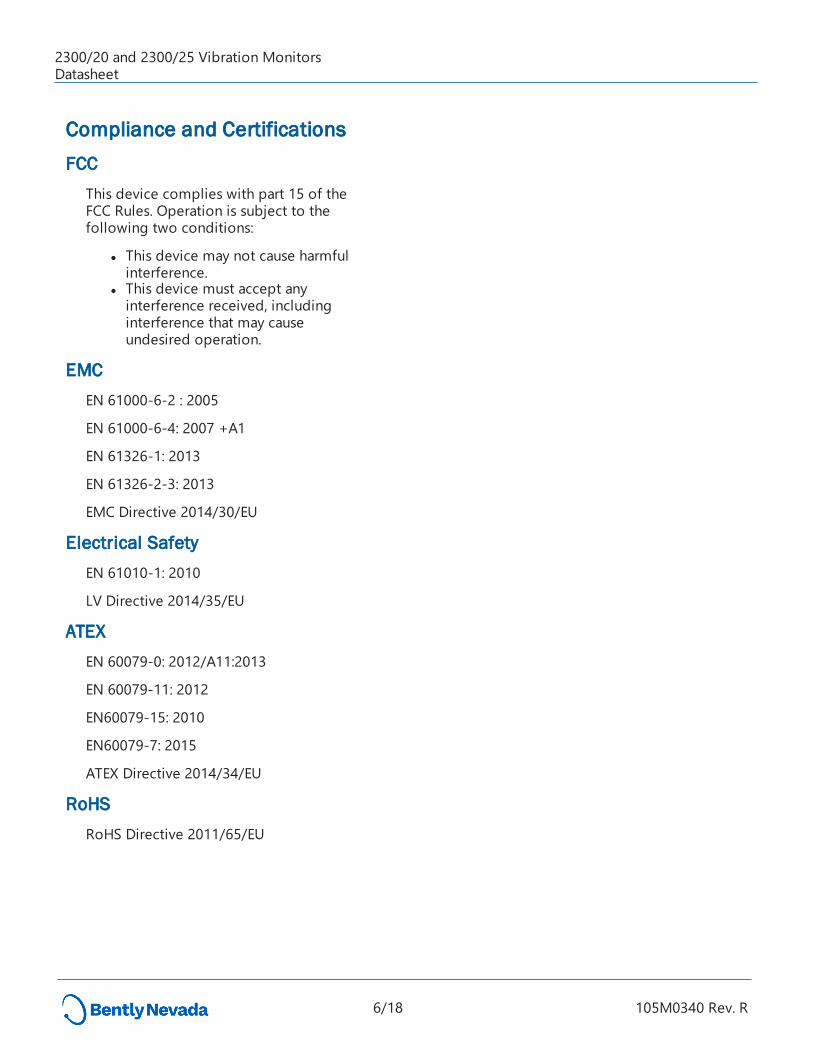
Compliance and CertificationsFCC
This device complies with part 15 of the FCC Rules. Operation is subject to the following two conditions:
l This device may not cause harmful interference.
l This device must accept any interference received, including interference that may cause undesired operation.
EMCEN 61000-6-2 : 2005
EN 61000-6-4: 2007 +A1
EN 61326-1: 2013
EN 61326-2-3: 2013
EMC Directive 2014/30/EU
Electrical SafetyEN 61010-1: 2010
LV Directive 2014/35/EU
ATEX EN 60079-0: 2012/A11:2013
EN 60079-11: 2012
EN60079-15: 2010
EN60079-7: 2015
ATEX Directive 2014/34/EU
RoHSRoHS Directive 2011/65/EU
2300/20 and 2300/25 Vibration MonitorsDatasheet
6/18 105M0340 Rev. R
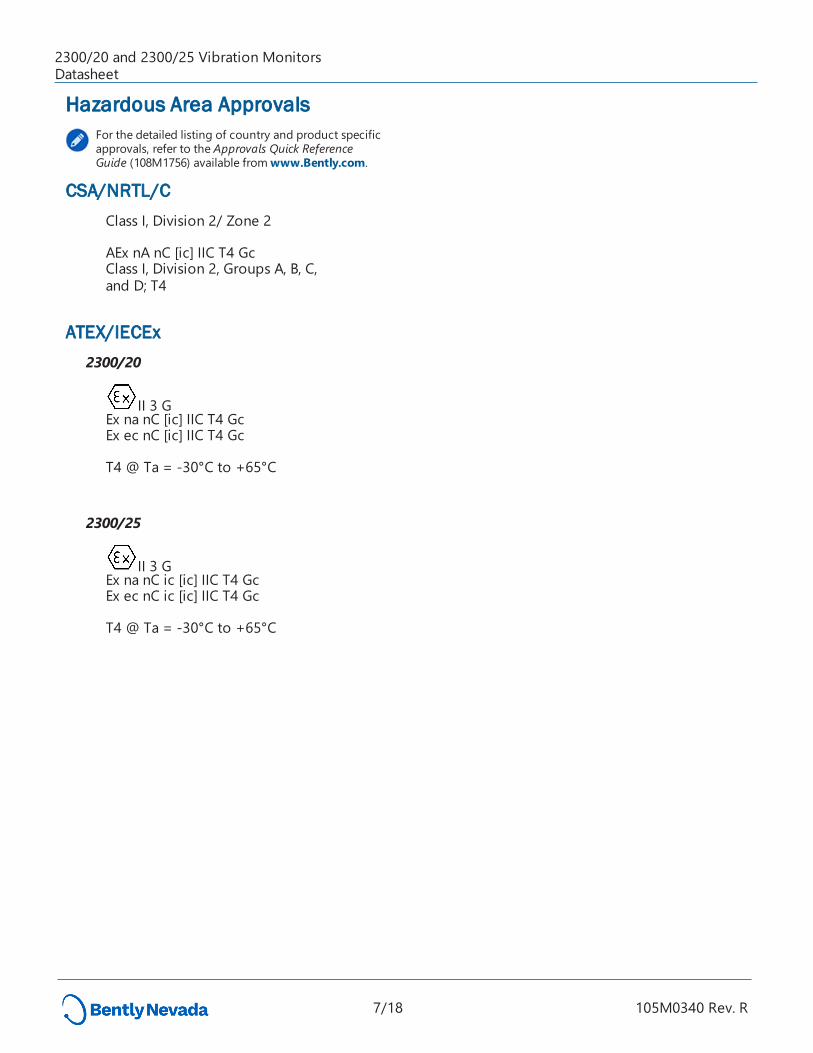
Hazardous Area ApprovalsFor the detailed listing of country and product specific approvals, refer to the Approvals Quick Reference Guide (108M1756) available from www.Bently.com.
CSA/NRTL/CClass I, Division 2/ Zone 2 AEx nA nC [ic] IIC T4 Gc Class I, Division 2, Groups A, B, C, and D; T4
ATEX/IECEx2300/20
II 3 GEx na nC [ic] IIC T4 GcEx ec nC [ic] IIC T4 Gc T4 @ Ta = -30°C to +65°C
2300/25
II 3 GEx na nC ic [ic] IIC T4 GcEx ec nC ic [ic] IIC T4 Gc T4 @ Ta = -30°C to +65°C
2300/20 and 2300/25 Vibration MonitorsDatasheet
7/18 105M0340 Rev. R
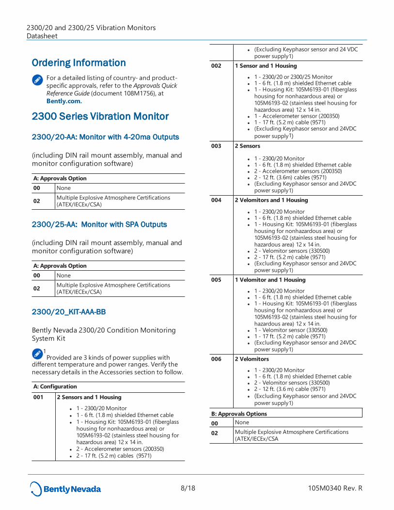
Ordering InformationFor a detailed listing of country- and product-specific approvals, refer to the Approvals Quick Reference Guide (document 108M1756), at Bently.com.
2300 Series Vibration Monitor
2300/20-AA: Monitor with 4-20ma Outputs
(including DIN rail mount assembly, manual and monitor configuration software)
A: Approvals Option 00 None
02 Multiple Explosive Atmosphere Certifications(ATEX/IECEx/CSA)
2300/25-AA: Monitor with SPA Outputs
(including DIN rail mount assembly, manual and monitor configuration software)
A: Approvals Option 00 None
02 Multiple Explosive Atmosphere Certifications(ATEX/IECEx/CSA)
2300/20_KIT-AAA-BB
Bently Nevada 2300/20 Condition Monitoring System Kit
1Provided are 3 kinds of power supplies with
different temperature and power ranges. Verify the necessary details in the Accessories section to follow.
A: Configuration 001 2 Sensors and 1 Housing
l 1 - 2300/20 Monitor l 1 - 6 ft. (1.8 m) shielded Ethernet cable l 1 - Housing Kit: 105M6193-01 (fiberglass
housing for nonhazardous area) or 105M6193-02 (stainless steel housing for hazardous area) 12 x 14 in.
l 2 - Accelerometer sensors (200350) l 2 - 17 ft. (5.2 m) cables (9571)
l (Excluding Keyphasor sensor and 24 VDC power supply1)
002 1 Sensor and 1 Housing
l 1 - 2300/20 or 2300/25 Monitor l 1 - 6 ft. (1.8 m) shielded Ethernet cable l 1 - Housing Kit: 105M6193-01 (fiberglass
housing for nonhazardous area) or 105M6193-02 (stainless steel housing for hazardous area) 12 x 14 in.
l 1 - Accelerometer sensor (200350) l 1 - 17 ft. (5.2 m) cable (9571) l (Excluding Keyphasor sensor and 24VDC
power supply1)003 2 Sensors
l 1 - 2300/20 Monitor l 1 - 6 ft. (1.8 m) shielded Ethernet cable l 2 - Accelerometer sensors (200350) l 2 - 12 ft. (3.6m) cables (9571) l (Excluding Keyphasor sensor and 24VDC
power supply1)004 2 Velomitors and 1 Housing
l 1 - 2300/20 Monitor l 1 - 6 ft. (1.8 m) shielded Ethernet cable l 1 - Housing Kit: 105M6193-01 (fiberglass
housing for nonhazardous area) or 105M6193-02 (stainless steel housing for hazardous area) 12 x 14 in.
l 2 - Velomitor sensors (330500) l 2 - 17 ft. (5.2 m) cable (9571) l (Excluding Keyphasor sensor and 24VDC
power supply1)005 1 Velomitor and 1 Housing
l 1 - 2300/20 Monitor l 1 - 6 ft. (1.8 m) shielded Ethernet cable l 1 - Housing Kit: 105M6193-01 (fiberglass
housing for nonhazardous area) or 105M6193-02 (stainless steel housing for hazardous area) 12 x 14 in.
l 1 - Velomitor sensor (330500) l 1 - 17 ft. (5.2 m) cable (9571) l (Excluding Keyphasor sensor and 24VDC
power supply1)006 2 Velomitors
l 1 - 2300/20 Monitor l 1 - 6 ft. (1.8 m) shielded Ethernet cable l 2 - Velomitor sensors (330500) l 2 - 12 ft. (3.6 m) cable (9571) l (Excluding Keyphasor sensor and 24VDC
power supply1)
B: Approvals Options 00 None
02 Multiple Explosive Atmosphere Certifications (ATEX/IECEx/CSA
2300/20 and 2300/25 Vibration MonitorsDatasheet
8/18 105M0340 Rev. R
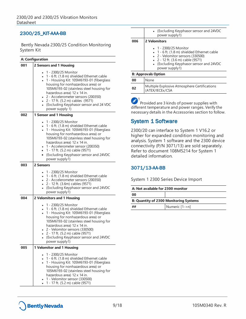
2300/25_KIT-AAA-BB
Bently Nevada 2300/25 Condition Monitoring System Kit
A: Configuration 001 2 Sensors and 1 Housing
l 1 - 2300/25 Monitor l 1 - 6 ft. (1.8 m) shielded Ethernet cable l 1 - Housing Kit: 105M6193-01 (fiberglass
housing for nonhazardous area) or 105M6193-02 (stainless steel housing for hazardous area) 12 x 14 in.
l 2 - Accelerometer sensors (200350) l 2 - 17 ft. (5.2 m) cables (9571) l (Excluding Keyphasor sensor and 24 VDC
power supply 1)002 1 Sensor and 1 Housing
l 1 - 2300/25 Monitor l 1 - 6 ft. (1.8 m) shielded Ethernet cable l 1 - Housing Kit: 105M6193-01 (fiberglass
housing for nonhazardous area) or 105M6193-02 (stainless steel housing for hazardous area) 12 x 14 in.
l 1 - Accelerometer sensor (200350) l 1 - 17 ft. (5.2 m) cable (9571) l (Excluding Keyphasor sensor and 24VDC
power supply1)003 2 Sensors
l 1 - 2300/25 Monitor l 1 - 6 ft. (1.8 m) shielded Ethernet cable l 2 - Accelerometer sensors (200350) l 2 - 12 ft. (3.6m) cables (9571) l (Excluding Keyphasor sensor and 24VDC
power supply1)004 2 Velomitors and 1 Housing
l 1 - 2300/25 Monitor l 1 - 6 ft. (1.8 m) shielded Ethernet cable l 1 - Housing Kit: 105M6193-01 (fiberglass
housing for nonhazardous area) or 105M6193-02 (stainless steel housing for hazardous area) 12 x 14 in.
l 2 - Velomitor sensors (330500) l 2 - 17 ft. (5.2 m) cable (9571) l (Excluding Keyphasor sensor and 24VDC
power supply1)005 1 Velomitor and 1 Housing
l 1 - 2300/25 Monitor l 1 - 6 ft. (1.8 m) shielded Ethernet cable l 1 - Housing Kit: 105M6193-01 (fiberglass
housing for nonhazardous area) or 105M6193-02 (stainless steel housing for hazardous area) 12 x 14 in.
l 1 - Velomitor sensor (330500) l 1 - 17 ft. (5.2 m) cable (9571)
l (Excluding Keyphasor sensor and 24VDC power supply1)
006 2 Velomitors
l 1 - 2300/25 Monitor l 1 - 6 ft. (1.8 m) shielded Ethernet cable l 2 - Velomitor sensors (330500) l 2 - 12 ft. (3.6 m) cable (9571) l (Excluding Keyphasor sensor and 24VDC
power supply1)B: Approvals Option 00 None
02 Multiple Explosive Atmosphere Certifications (ATEX/IECEx/CSA
1Provided are 3 kinds of power supplies with
different temperature and power ranges. Verify the necessary details in the Accessories section to follow.
System 1 Software 2300/20 can interface to System 1 V16.2 or higher for expanded condition monitoring and analysis. System 1 software and the 2300 device connectivity (P/N 3071/13) are sold separately. Refer to document 108M5214 for System 1 detailed information.
3071/13-AA-BB
System 1 2300 Series Device Import
A: Not available for 2300 monitor00 B: Quantity of 2300 Monitoring Systems## Numeric [1->n]
2300/20 and 2300/25 Vibration MonitorsDatasheet
9/18 105M0340 Rev. R
Accessories
106M7607-01 Power supply for DIN rail mounting, 100/240AC to 24DC/1.5ACertifications (ATEX) (-25°C ~70°C, 35*99*95 mm) (One power can drive max 4 monitors)
110M7102-01 Power supply for DIN rail mounting, 100/240AC to 24DC/1.3ACertifications (CID2 by UL) (-25°C ~70°C, 22.5*99*107 mm) (One power can drive max 4 monitors.)
106M6694-01 Power supply for DIN rail mounting, 110/220AC to 24VDC/5ACertifications (ATEX, IECEx, CID2 by UL) (-40°C ~70°C, 40*130*125 mm) (One power can drive max 10 monitors.)
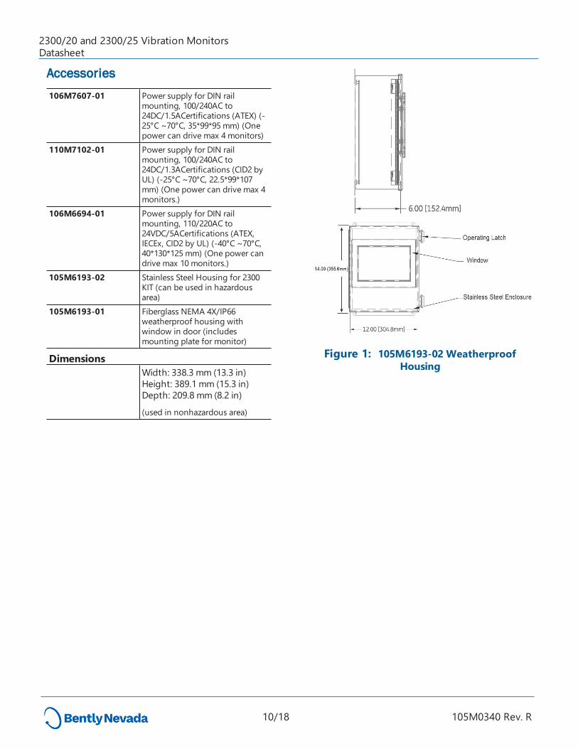
105M6193-02 Stainless Steel Housing for 2300 KIT (can be used in hazardous area)
105M6193-01 Fiberglass NEMA 4X/IP66 weatherproof housing with window in door (includes mounting plate for monitor)
Dimensions Width: 338.3 mm (13.3 in)
Height: 389.1 mm (15.3 in)Depth: 209.8 mm (8.2 in)
(used in nonhazardous area)
Figure 1: 105M6193-02 Weatherproof Housing
2300/20 and 2300/25 Vibration MonitorsDatasheet
10/18 105M0340 Rev. R
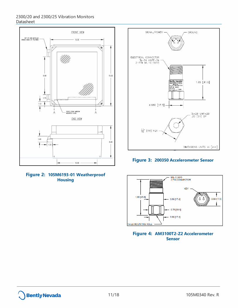
Figure 2: 105M6193-01 Weatherproof Housing
Figure 3: 200350 Accelerometer Sensor
Figure 4: AM3100T2-Z2 Accelerometer Sensor
2300/20 and 2300/25 Vibration MonitorsDatasheet
11/18 105M0340 Rev. R
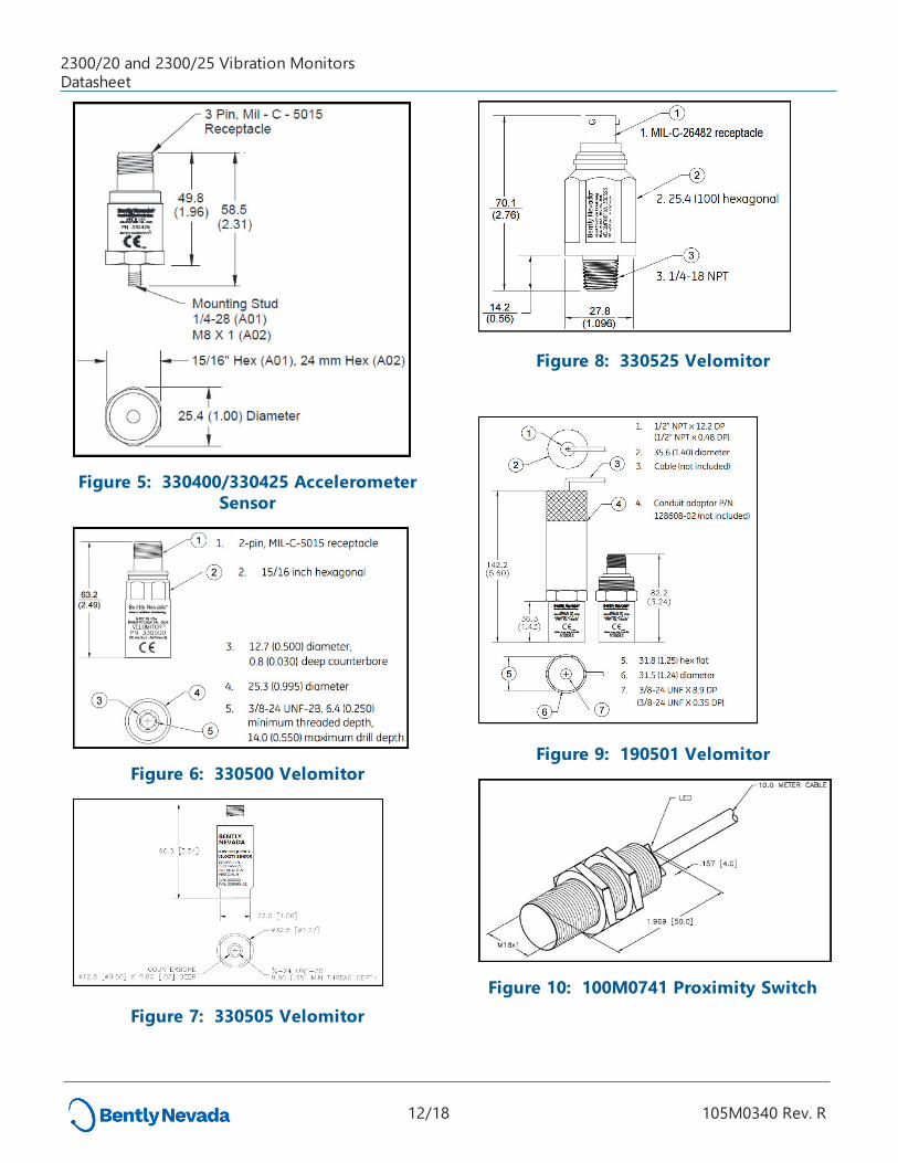
Figure 5: 330400/330425 Accelerometer Sensor
Figure 6: 330500 Velomitor
Figure 7: 330505 Velomitor
Figure 8: 330525 Velomitor
Figure 9: 190501 Velomitor
Figure 10: 100M0741 Proximity Switch
2300/20 and 2300/25 Vibration MonitorsDatasheet
12/18 105M0340 Rev. R
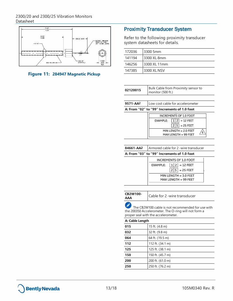
Figure 11: 284947 Magnetic Pickup
Proximity Transducer SystemRefer to the following proximity transducer system datasheets for details.
172036 3300 5mm141194 3300 XL 8mm146256 3300 XL 11mm147385 3300 XL NSV
02120015 Bulk Cable from Proximity sensor to monitor (500 ft.)
9571-AA2 Low cost cable for accelerometerA: From “02” to “99” Increments of 1.0 foot
84661-AA2 Armored cable for 2 -wire transducerA: From “03” to “99” Increments of 1.0 foot
CB2W100-AAA Cable for 2 -wire transducer
The CB2W100 cable is not recommended for use with the 200350 Accelerometer. The O-ring will not form a proper seal with the accelerometer.A: Cable Length 015 15 ft. (4.8 m) 032 32 ft. (9.8 m) 064 64 ft. (19.5 m) 112 112 ft. (34.1 m) 125 125 ft. (38.1 m) 150 150 ft. (45.7 m) 200 200 ft. (61.0 m) 250 250 ft. (76.2 m)
2300/20 and 2300/25 Vibration MonitorsDatasheet
13/18 105M0340 Rev. R
Splash Proof Cable for 2-wire transducer
9571 Mod : 285031-AA2
Cable for 2-wire extension with Splash Proof Connection. This cable assembly provides an equivalent IP66 level of protection.
A: Cable Lengths 16 16 ft. (4.8 m) 32 32 ft. (9.8 m) 64 64 ft. (19.5 m)
For Proximitor 3300-NSV and Accelerometer 330400, you will need metal conduit for conducted RF performance.
2Cable lengths greater than 30 meters (100 feet)
will experience some attenuation of amplitudes at higher frequencies when using the AM3100T2-Z2 Accelerometer.
286244 Magnetic mounting base ¼-28 threaded hole
Ethernet Cables
138131-AAA
Standard 10 Base-T/100 Base-TX Shielded Category 5 Cable with RJ-45 connectors (solid conductor)
A: Cable Length 006 6 ft. (1.8 m) 010 0 10 ft. (3.0 m) 025 25 ft. (7.6 m)040 40 ft. (12.2 m) 050 50 ft. (15.2 m) 075 75 ft. (22.9 m) 085 85 ft. (25.9 m) 100 100 ft. (30.5 m)
Spares
105M6203- 35mm DIN rail mount and screws (included
01 with 2300/20 monitor)106M3210 10-pin 4-20mA output connector106M2223 5-pin contact input connector (Alarm
Reset)106M3408 5-pin contact input connector (Alarm
Inhibit, Config lock)106M3211 16-pin transducer input connector106M3212 6-pin relay output connector106M2231 3-pin power input connector
Accessories
02120015 Bulk Cable from Proximity sensor to monitor (500 ft.)
9571-AA2 Low cost cable for 2-wire transducer
Software
100M9465-01 BN Monitor Configuration SW/FW DVD
l BNMC version 5.2 or greater
l 2300 series monitor firmware
l (DVD includes 2300 Series Software Guide)
Additional Information2300 Series Operation and Maintenance Manual (Document 105M0341)
2300 Field Wiring Diagram (Document 106M5801)
2300 Series Software Guide (Document 107M7626)
2300 Series Monitor Installation Guide (Document 121M3029)
2300/20 and 2300/25 Vibration MonitorsDatasheet
14/18 105M0340 Rev. R
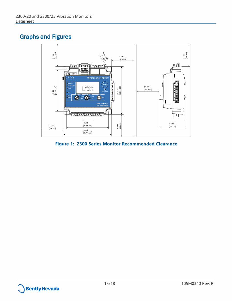
Graphs and Figures
Figure 1: 2300 Series Monitor Recommended Clearance
15/18 105M0340 Rev. R
2300/20 and 2300/25 Vibration MonitorsDatasheet
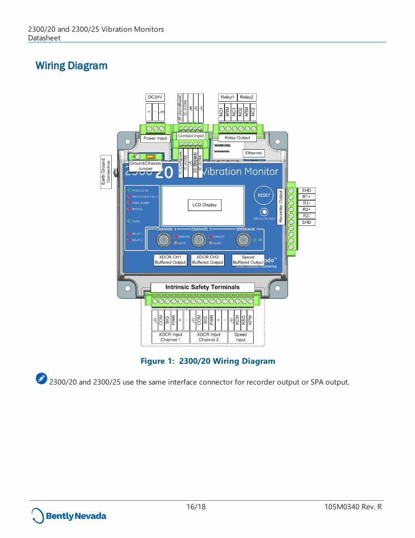
Wiring Diagram
Figure 1: 2300/20 Wiring Diagram
2300/20 and 2300/25 use the same interface connector for recorder output or SPA output.
16/18 105M0340 Rev. R
2300/20 and 2300/25 Vibration MonitorsDatasheet
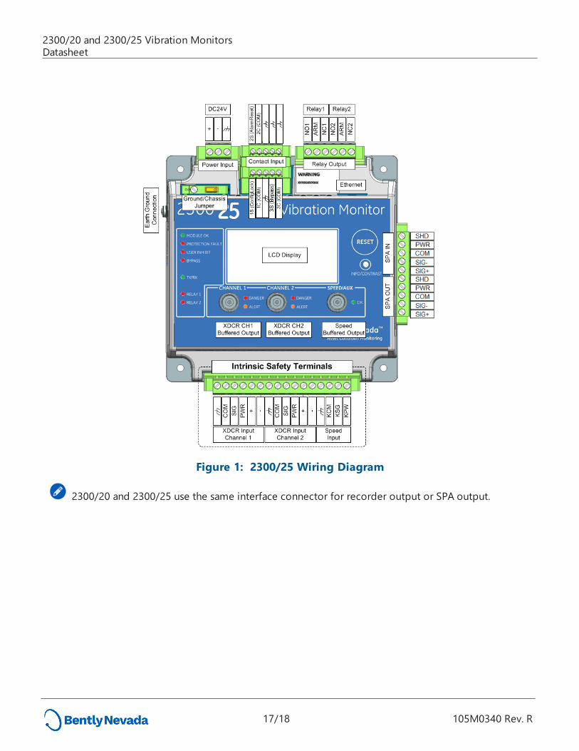
Figure 1: 2300/25 Wiring Diagram
2300/20 and 2300/25 use the same interface connector for recorder output or SPA output.
2300/20 and 2300/25 Vibration MonitorsDatasheet
17/18 105M0340 Rev. R
Copyright 2019 Baker Hughes, a GE company, LLC ("BHGE") All rights reserved.
Bently Nevada, Orbit Logo, System 1, Velomitor, Proximitor and Keyphasor are registered trademarks of BHGE in the United States and other countries. All product and company names are trademarks of their
respective holders. Use of the trademarks does not imply any affiliation with or endorsement by the respective holders. This product may be covered by one or more patents, please see Bently.com/legal
for current status. The information contained in this document is subject to change without prior notice.
1631 Bently Parkway South, Minden, Nevada USA 89423Phone: 1.775.782.3611 Bently.com
2300/20 and 2300/25 Vibration MonitorsDatasheet
18/18 105M0340 Rev. R