2013 golf, gti & golf r - static.nhtsa.gov · vw golf & gti quick reference specification...
TRANSCRIPT
Golf, GTI & Golf RQuick Reference Specification Book
2013

VW Golf & GTI Quick Reference Specification Book • September 2012 i
2013 Volkswagen Golf & GTI Quick Reference Specification Book
TaBle of ConTenTSGeneral Information ...................................................... 1
Decimal and Metric Equivalents ...........................................1Tightening Torque .................................................................2 Warnings and Cautions ........................................................4
Vehicle Identification ..................................................... 9Vehicle Identification Number (VIN) Location ..........................9VIN Decoder ..........................................................................10VIN on Longitudinal Member Extension ................................11Vehicle Data Label .................................................................12
Sales Codes ................................................................. 13Engine Codes ........................................................................13Transmission Codes ..............................................................13
Vehicle Lifting .............................................................. 14Hoist and Jack Mounting Points .........................................14
Front ......................................................................................14Rear .......................................................................................15
ENGINESEngine Mechanical – 2.0L CJAA (TDI) ....................... 16
General, Technical Data .....................................................16Engine Number Location .......................................................16Engine Data ...........................................................................17
Engine Assembly - 2.0L CJAA (TDI) ...................................18Fastener Tightening Specifications ........................................18Engine Mount Tightening Specifications ................................18Transmission Mount Tightening Specifications ......................19Pendulum Support Tightening Specifications ........................20Engine Mount Bracket Tightening Specifications ..................21
Crankshaft, Cylinder Block – 2.0L CJAA (TDI) ...................22Fastener Tightening Specifications ........................................22Accessory Bracket Tightening Specifications ........................24Crankshaft Dimensions .........................................................25Piston and Cylinder Dimensions ............................................25Piston Ring End Gaps ...........................................................25Piston Ring Clearance ...........................................................25
ii VW Golf & GTI Quick Reference Specification Book • September 2012
Cylinder Head, Valvetrain – 2.0L CJAA (TDI) .....................26Fastener Tightening Specifications ........................................26Valve Dimensions ..................................................................27Compression Pressures ........................................................27Cylinder Head Cover Tightening Specifications ....................28Cylinder Head Tightening Specifications ...............................29Bearing Frame Tightening Specifications ..............................30
Lubrication – 2.0L CJAA (TDI) ............................................31Fastener Tightening Specifications ........................................31
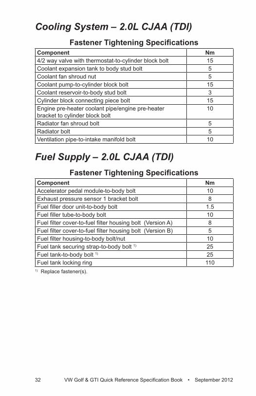
Cooling System – 2.0L CJAA (TDI) ....................................32Fastener Tightening Specifications ........................................32
Fuel Supply – 2.0L CJAA (TDI)...........................................32Fastener Tightening Specifications ........................................32
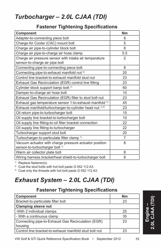
Turbocharger – 2.0L CJAA (TDI) ........................................33Fastener Tightening Specifications ........................................33
Exhaust System – 2.0L CJAA (TDI)....................................33Fastener Tightening Specifications ........................................33
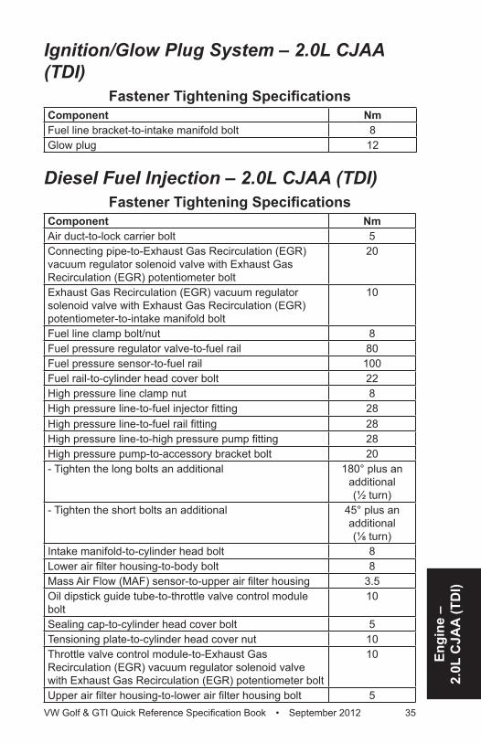
Ignition/Glow Plug System – 2.0L CJAA (TDI)....................35Fastener Tightening Specifications ........................................35
Diesel Fuel Injection – 2.0L CJAA (TDI) .............................35Fastener Tightening Specifications ........................................35
ENGINE MECHANICAL – 2.0L CBFA, CCTA ............. 36General, Technical Data .....................................................36
Engine Number Location .......................................................36Engine Data ...........................................................................37
Engine Assembly – 2.0L CBFA, CCTA ...............................38Fastener Tightening Specifications ........................................38
Crankshaft, Cylinder Block – 2.0L CBFA, CCTA .................39Cylinder Block Bearing Shell Identification ............................39Bearing Cap Bearing Shell Identification ...............................41Fastener Tightening Specifications ........................................42Crankshaft Dimensions .........................................................43Piston Ring End Gaps ...........................................................43Piston Ring Clearance ...........................................................43Piston and Cylinder Dimensions ............................................43Accessory Assembly Bracket Tightening Specifications ........44Sealing Flange Tightening Specifications ..............................45Crankshaft Assembly Tightening Specifications ....................46
Cylinder Head, Valvetrain – 2.0L CBFA, CCTA ..................47Fastener Tightening Specifications ........................................47Valve Dimensions ..................................................................48
VW Golf & GTI Quick Reference Specification Book • September 2012 iii
Compression Pressures ........................................................48Cylinder Head Tightening Specifications ...............................49Cylinder Head Cover Tightening Specifications ....................50Crankcase Ventilation Tightening Specification .....................51Upper Timing Chain Cover Tightening Specifications ...........51Lower Timing Chain Cover Tightening Specifications
with 15 Bolts ....................................................................52Lower Timing Chain Cover Tightening Specifications
with 8 Bolts ......................................................................53Lubrication – 2.0L CBFA, CCTA .........................................54
Fastener Tightening Specifications ........................................54Upper Oil Pan Tightening Specifications ...............................54Oil Pan Tightening Specifications ..........................................55Oil Separator Tightening Specification ..................................56
Cooling System – 2.0L CBFA, CCTA ..................................56Fastener Tightening Specifications ........................................56Coolant Pump Tightening Specification .................................57
Fuel Supply – 2.0L CBFA, CCTA ........................................57Fastener Tightening Specifications ........................................57
Turbocharger, G-Charger – 2.0L CBFA, CCTA ...................58Fastener Tightening Specifications ........................................58Turbocharger Tightening Specifications ................................59
Exhaust System – 2.0L CBFA, CCTA .................................60Fastener Tightening Specifications ........................................60
Multiport Fuel Injection – 2.0L CBFA, CCTA .......................60Technical Data .......................................................................60Fastener Tightening Specifications ........................................61
Ignition – 2.0L CBFA, CCTA ...............................................62Technical Data .......................................................................62Fastener Tightening Specifications ........................................62
ENGINE MECHANICAL – 2.0L CRZA .......................... 63General, Technical Data .....................................................63
Engine Number Location .......................................................63Engine Data ...........................................................................64
Engine Assembly – 2.0L CRZA...........................................65Fastener Tightening Specifications ........................................65Engine Mount Tightening Specifications ................................65Transmission Mount Tightening Specifications ......................66Pendulum Support Tightening Specifications ........................67
Crankshaft, Cylinder Block – 2.0L CRZA ............................68Upper Crankshaft Bearing Identification ................................68
iv VW Golf & GTI Quick Reference Specification Book • September 2012
Fastener Tightening Specifications ........................................69Crankshaft Dimensions .........................................................70Piston Ring End Gaps ...........................................................70Piston Ring Clearance ...........................................................70Piston and Cylinder Dimensions ............................................70Accessory Assembly Bracket Tightening Specification .........71Sealing Flange Tightening Specifications ..............................72
Cylinder Head, Valvetrain – 2.0L CRZA ..............................73Fastener Tightening Specifications ........................................73Valve Dimensions ..................................................................74Compression Pressures ........................................................74Cylinder Head Tightening Specifications ...............................75Cylinder Head Cover Tightening Specification ......................76
Lubrication – 2.0L CRZA.....................................................77Fastener Tightening Specifications ........................................77Oil Pan Tightening Specifications ..........................................78
Cooling System – 2.0L CRZA .............................................79Fastener Tightening Specifications ........................................79
Fuel Supply – 2.0L CRZA ...................................................79Fastener Tightening Specifications ........................................79
Turbocharger, G-Charger – 2.0L CRZA ..............................80Fastener Tightening Specifications ........................................80
Exhaust System – 2.0L CRZA ............................................81Fastener Tightening Specifications ........................................81
Multiport Fuel Injection – 2.0L CRZA ..................................81Technical Data .......................................................................81Fastener Tightening Specifications ........................................82
Ignition – 2.0L CRZA...........................................................83Technical Data .......................................................................83Fastener Tightening Specifications ........................................83
Engine Mechanical – 2.5L CBTA, CBUA .................... 84General, Technical Data .....................................................84
Engine Number ......................................................................84Engine Data ...........................................................................85Cylinder Numbering ..............................................................86
Engine Assembly – 2.5L CBTA, CBUA ...............................87Fastener Tightening Specifications ........................................87Engine Mount Tightening Specifications ................................87Transmission Mount Tightening Specifications ......................88Pendulum Support Tightening Specifications ........................89
VW Golf & GTI Quick Reference Specification Book • September 2012 v
Crankshaft, Cylinder Block – 2.5L CBTA, CBUA ................90Crankshaft Upper Bearing Shell (for Cylinder Block)
Allocation .........................................................................90Crankshaft Lower Bearing Shell (for Bearing Cap)
Allocation .........................................................................91Fastener Tightening Specifications ........................................92Crankshaft Dimensions .........................................................93Piston and Cylinder Dimensions ............................................93Piston Ring End Gap .............................................................94Piston Ring Clearance ...........................................................94
Cylinder Head, Valvetrain – 2.5L CBTA, CBUA ..................95Fastener Tightening Specifications ........................................95Valve Dimensions ..................................................................96Compression Pressures ........................................................96Cylinder Head Cover Tightening Specification ......................97Cylinder Head Tightening Specifications ...............................98Guide Frame Tightening Specifications .................................99
Lubrication – 2.5L CBTA, CBUA .......................................100Fastener Tightening Specifications ......................................100
Cooling System – 2.5L CBTA, CBUA ...............................101Fastener Tightening Specifications ......................................101
Fuel Supply – 2.5L CBTA, CBUA ......................................101Fastener Tightening Specifications ......................................101
Exhaust System, Emission Controls – 2.5L CBTA, CBUA .............................................................102
Fastener Tightening Specifications ......................................102Secondary Air Injection Pipe Tightening Specifications .......103
Multiport Fuel Injection – 2.5L CBTA, CBUA ....................104Fastener Tightening Specifications ......................................104Lower Air Filter Housing
Bolt Tightening Specifications ......................................104Ignition – 2.5L CBTA, CBUA .............................................105
Fastener Tightening Specifications ......................................105Technical Data .....................................................................105
TRANSMISSIONSManual Transmission – 0A4 ..................................... 106
General, Technical Data ...................................................106Transmission Identification ..................................................106Codes Letters, Transmission Allocation and Capacities ......108
vi VW Golf & GTI Quick Reference Specification Book • September 2012
Clutch – 0A4 .....................................................................109Fastener Tightening Specifications ......................................109
Controls, Housing – 0A4 ...................................................110Fastener Tightening Specifications ......................................110Transmission to Engine Tightening Specifications .............. 111Transmission Mount Bracket to Transmission Bolt
Tightening Specification ................................................112Transmission Mount to Transmission Mount Bracket Bolt
Tightening Specification ................................................113Transmission Support to Transmission Bracket and
Transmission Bolt Tightening Specification ...................114Reverse Shaft Support to Transmission Housing Bolt
Tightening Sequence and Specification ........................115Gears, Shafts – 0A4 .........................................................116
Fastener Tightening Specification .......................................116Determining Shim Thickness ...............................................116Adjustment Shim Table ........................................................116
Manual Transmission – 02Q ......................................118General, Technical Data ...................................................118
Transmission Identification ..................................................118Codes Letters, Transmission Allocation and Capacities ......120
Clutch – 02Q .....................................................................121Fastener Tightening Specifications ......................................121
Controls, Housing – 02Q ..................................................122Transmission to Engine Tightening Specifications ..............122Front Wheel Drive Fastener Tightening Specifications ........122Adjustment Shim Table ........................................................123
Rear Final Drive, Differential – 02Q ..................................124Fastener Tightening Specifications ......................................124All Wheel Drive Fastener Tightening Specifications ............124Transmission Mount ............................................................125Brace under Diaphragm ......................................................126Transmission Bracket to Transmission ................................127Identification on Transmission .............................................128
Automatic Transmission – 09G ................................ 129General, Technical Data ...................................................129
Identification on Transmission .............................................129Code Letters, Assembly Allocation and Ratios ....................130
Controls, Housing .............................................................131Fastener Tightening Specifications ......................................131Transmission to Engine Tightening Specifications ..............132
VW Golf & GTI Quick Reference Specification Book • September 2012 vii
Gears, Hydraulic Controls – 09G ......................................133Fastener Tightening Specifications ......................................133Transmission Fluid Pan Tightening Specification ................134
Direct Shift Gearbox (DSG) Transmission – 02E .... 135General, Technical Data ...................................................135
Identification on Transmission .............................................135Transmission Allocation Codes ............................................137
Controls, Housing (DSG) – 02E .......................................138Fastener Tightening Specifications ......................................138Mechatronic Tightening Specifications ................................139Oil Pump Tightening Specifications
Without Countersunk Bolt .............................................140With Countersunk Bolt .........................................................140Oil Pump Cover Tightening Specifications ..........................141Transmission Mount Tightening Specifications ....................142Transmission to Engine Tightening Specifications ..............143
CHASSISSuspension, Wheels, Steering ................................. 144
Front Suspension .............................................................144Fastener Tightening Specifications ......................................144
Rear Suspension ..............................................................146Fastener Tightening Specifications ......................................146
Self-Leveling Suspension .................................................148Fastener Tightening Specifications ......................................148
Wheels, Tires, Wheel Alignment .......................................148Fastener Tightening Specifications ......................................148
Wheel Alignment Data ......................................................149Wheel Alignment Specified Values ......................................149
Steering ............................................................................154Fastener Tightening Specifications ......................................154
Brake System ............................................................. 156General, Technical Data ...................................................156
Vehicle Data Sticker PR Number Allocation ........................156Front Brakes ........................................................................157Rear Brakes .........................................................................157Brake Master Cylinder and Brake Booster ..........................157Front Brakes ........................................................................158Rear Brakes C38 .................................................................160
viii VW Golf & GTI Quick Reference Specification Book • September 2012
Anti-lock Brake System (ABS) ..........................................161Fastener Tightening Specifications ......................................161
Mechanical Components ..................................................161Fastener Tightening Specifications ......................................161
Hydraulic Components .....................................................162Fastener Tightening Specifications ......................................162
Body ............................................................................ 163Air Gap Body Dimensions ................................................163
Body, Front ..........................................................................163Body, Center ........................................................................164Body, Rear ...........................................................................165
Body Exterior ....................................................................166Bulkhead, Front Fender Tightening Specifications ..............166Lock Carrier Tightening Specifications ................................166Underbody Trim, Noise Insulation Tightening
Specifications ................................................................166Tunnel Bridge, Plenum Chamber Tightening
Specifications ................................................................167Front Hood Tightening Specifications ..................................167Rear Lid, Fuel Filler Door Tightening Specifications ............167Front and Rear Door Tightening Specifications ...................167Sunroof Tightening Specifications .......................................168Front Bumper Tightening Specifications ..............................168Rear Bumper, Trailer Hitch Tightening Specifications .........168Mirror Tightening Specifications ..........................................168Exterior Equipment Tightening Specifications .....................168
Body Interior .....................................................................169Storage Compartments, Covers and Trim Tightening
Specifications ................................................................169Passenger Protection Fastener Tightening Specifications ..169Interior Trim Fastener Tightening Specifications .................170Seat Frames Fastener Tightening Specifications ................170
Heating, Ventilation and Air Conditioning ............... 171General, Technical Data ...................................................171
Refrigerant Oil Distribution ..................................................171Refrigerant R134a Vapor Pressure Table ............................172
Heating, Ventilation ...........................................................173Fastener Tightening Specifications ......................................173
Air Conditioning ................................................................174Fastener Tightening Specifications ......................................174
VW Golf & GTI Quick Reference Specification Book • September 2012 ix
Electrical System ....................................................... 175Electrical Equipment .........................................................175
Battery, Starter, Generator, Cruise Control Fastener Tightening Specifications ..............................................175
Windshield Wiper/Washer Tightening Specifications ...........176Exterior Lights, Switches Tightening Specifications ............176Interior Lights, Switches Tightening Specifications ..............176Wiring Tightening Specification ...........................................176Left E-box in Engine Compartment Tightening
Specifications ................................................................177
DTC Chart ................................................................... 178Engine Codes CBFA .........................................................178
Fuel and Air Mixture, Additional Emission Regulations ...................................178
Ignition System ....................................................................185Additional Exhaust Regulation .............................................187Speed and Idle Control ........................................................189Control Module and Output Signals .....................................189Fuel and Air Ratios Control Module .....................................191Additional Emissions Regulations .......................................194
DTC Chart ................................................................... 196Engine Codes CCTA .........................................................196
Fuel and Air Mixture, Additional Emission Regulations ...................................196
Ignition System ....................................................................202Additional Exhaust Regulation .............................................204Speed and Idle Control ........................................................205Control Module and Output Signals .....................................205Fuel and Air Ratios Control Module .....................................207Additional Emissions Regulations .......................................210
DTC Chart ....................................................................211Engine Codes CJAA ........................................................211
Fuel and Air Mixture, Additional Emission Regulations ...................................211
Fuel and Air Ratios Control Module ....................................222Ignition System ....................................................................223Additional Exhaust Regulation .............................................224Speed and Idle Control ........................................................228Control Module and Output Signals .....................................229
x VW Golf & GTI Quick Reference Specification Book • Sepetember 2012
DTC Chart ................................................................... 233Engine Codes CRZA ........................................................233
Fuel and Air Mixture, Additional Emission Regulations .......233Ignition System ....................................................................239Additional Exhaust Regulation .............................................241Speed and Idle Control ........................................................242Control Module and Output Signals .....................................242Fuel and Air Ratios Control Module .....................................244Additional Emissions Regulations .......................................246
DTC Chart ................................................................... 248Engine Codes CBTA, CBUA .............................................248
Fuel and Air Mixture, Additional Emission Regulations ...................................248
Ignition System ....................................................................256Additional Exhaust Regulation .............................................258Speed and Idle Control ........................................................260Control Module and Output Signals .....................................260Fuel and Ratio Control Module ............................................262
Gen
eral
Info
rmat
ion
VW Golf & GTI Quick Reference Specification Book • September 2012 1
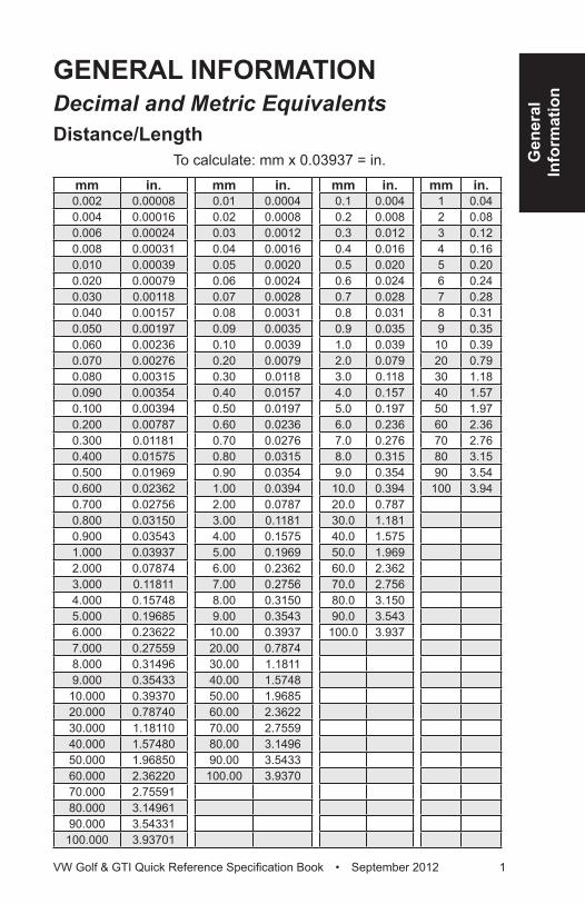
GENERAL INFORMATIONDecimal and Metric EquivalentsDistance/Length
To calculate: mm x 0.03937 = in.mm in. mm in. mm in. mm in.0.002 0.00008 0.01 0.0004 0.1 0.004 1 0.040.004 0.00016 0.02 0.0008 0.2 0.008 2 0.080.006 0.00024 0.03 0.0012 0.3 0.012 3 0.120.008 0.00031 0.04 0.0016 0.4 0.016 4 0.160.010 0.00039 0.05 0.0020 0.5 0.020 5 0.200.020 0.00079 0.06 0.0024 0.6 0.024 6 0.240.030 0.00118 0.07 0.0028 0.7 0.028 7 0.280.040 0.00157 0.08 0.0031 0.8 0.031 8 0.310.050 0.00197 0.09 0.0035 0.9 0.035 9 0.350.060 0.00236 0.10 0.0039 1.0 0.039 10 0.390.070 0.00276 0.20 0.0079 2.0 0.079 20 0.790.080 0.00315 0.30 0.0118 3.0 0.118 30 1.180.090 0.00354 0.40 0.0157 4.0 0.157 40 1.570.100 0.00394 0.50 0.0197 5.0 0.197 50 1.970.200 0.00787 0.60 0.0236 6.0 0.236 60 2.360.300 0.01181 0.70 0.0276 7.0 0.276 70 2.760.400 0.01575 0.80 0.0315 8.0 0.315 80 3.150.500 0.01969 0.90 0.0354 9.0 0.354 90 3.540.600 0.02362 1.00 0.0394 10.0 0.394 100 3.940.700 0.02756 2.00 0.0787 20.0 0.7870.800 0.03150 3.00 0.1181 30.0 1.1810.900 0.03543 4.00 0.1575 40.0 1.5751.000 0.03937 5.00 0.1969 50.0 1.9692.000 0.07874 6.00 0.2362 60.0 2.3623.000 0.11811 7.00 0.2756 70.0 2.7564.000 0.15748 8.00 0.3150 80.0 3.1505.000 0.19685 9.00 0.3543 90.0 3.5436.000 0.23622 10.00 0.3937 100.0 3.9377.000 0.27559 20.00 0.78748.000 0.31496 30.00 1.18119.000 0.35433 40.00 1.574810.000 0.39370 50.00 1.968520.000 0.78740 60.00 2.362230.000 1.18110 70.00 2.755940.000 1.57480 80.00 3.149650.000 1.96850 90.00 3.543360.000 2.36220 100.00 3.937070.000 2.7559180.000 3.1496190.000 3.54331100.000 3.93701
2 VW Golf & GTI Quick Reference Specification Book • Sepetember 2012
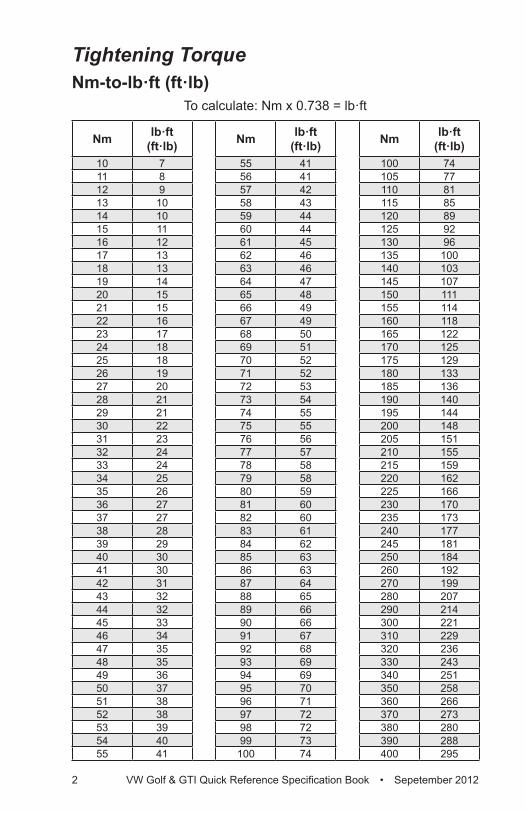
Tightening TorqueNm-to-lb·ft (ft·lb)
To calculate: Nm x 0.738 = lb·ft
Nm lb·ft (ft·lb) Nm lb·ft
(ft·lb) Nm lb·ft (ft·lb)
10 7 55 41 100 7411 8 56 41 105 7712 9 57 42 110 8113 10 58 43 115 8514 10 59 44 120 8915 11 60 44 125 9216 12 61 45 130 9617 13 62 46 135 10018 13 63 46 140 10319 14 64 47 145 10720 15 65 48 150 11121 15 66 49 155 11422 16 67 49 160 11823 17 68 50 165 12224 18 69 51 170 12525 18 70 52 175 12926 19 71 52 180 13327 20 72 53 185 13628 21 73 54 190 14029 21 74 55 195 14430 22 75 55 200 14831 23 76 56 205 15132 24 77 57 210 15533 24 78 58 215 15934 25 79 58 220 16235 26 80 59 225 16636 27 81 60 230 17037 27 82 60 235 17338 28 83 61 240 17739 29 84 62 245 18140 30 85 63 250 18441 30 86 63 260 19242 31 87 64 270 19943 32 88 65 280 20744 32 89 66 290 21445 33 90 66 300 22146 34 91 67 310 22947 35 92 68 320 23648 35 93 69 330 24349 36 94 69 340 25150 37 95 70 350 25851 38 96 71 360 26652 38 97 72 370 27353 39 98 72 380 28054 40 99 73 390 28855 41 100 74 400 295
Gen
eral
Info
rmat
ion
VW Golf & GTI Quick Reference Specification Book • September 2012 3
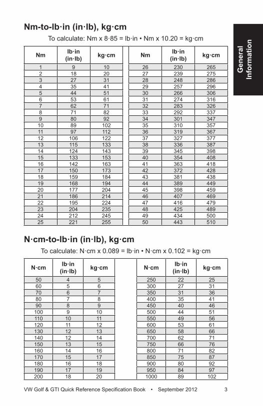
Nm-to-lb·in (in·lb), kg·cmTo calculate: Nm x 8·85 = lb·in • Nm x 10.20 = kg·cm
Nm lb·in (in·lb) kg·cm Nm lb·in
(in·lb) kg·cm
1 9 10 26 230 2652 18 20 27 239 2753 27 31 28 248 2864 35 41 29 257 2965 44 51 30 266 3066 53 61 31 274 3167 62 71 32 283 3268 71 82 33 292 3379 80 92 34 301 347
10 89 102 35 310 35711 97 112 36 319 36712 106 122 37 327 37713 115 133 38 336 38714 124 143 39 345 39815 133 153 40 354 40816 142 163 41 363 41817 150 173 42 372 42818 159 184 43 381 43819 168 194 44 389 44920 177 204 45 398 45921 186 214 46 407 46922 195 224 47 416 47923 204 235 48 425 48924 212 245 49 434 50025 221 255 50 443 510
N·cm-to-lb·in (in·lb), kg·cmTo calculate: N·cm x 0.089 = lb·in • N·cm x 0.102 = kg·cm
N·cm lb·in(in·lb) kg·cm N·cm lb·in
(in·lb) kg·cm
50 4 5 250 22 2560 5 6 300 27 3170 6 7 350 31 3680 7 8 400 35 4190 8 9 450 40 46
100 9 10 500 44 51110 10 11 550 49 56120 11 12 600 53 61130 12 13 650 58 66140 12 14 700 62 71150 13 15 750 66 76160 14 16 800 71 82170 15 17 850 75 87180 16 18 900 80 92190 17 19 950 84 97200 18 20 1000 89 102
4 VW Golf & GTI Quick Reference Specification Book • Sepetember 2012
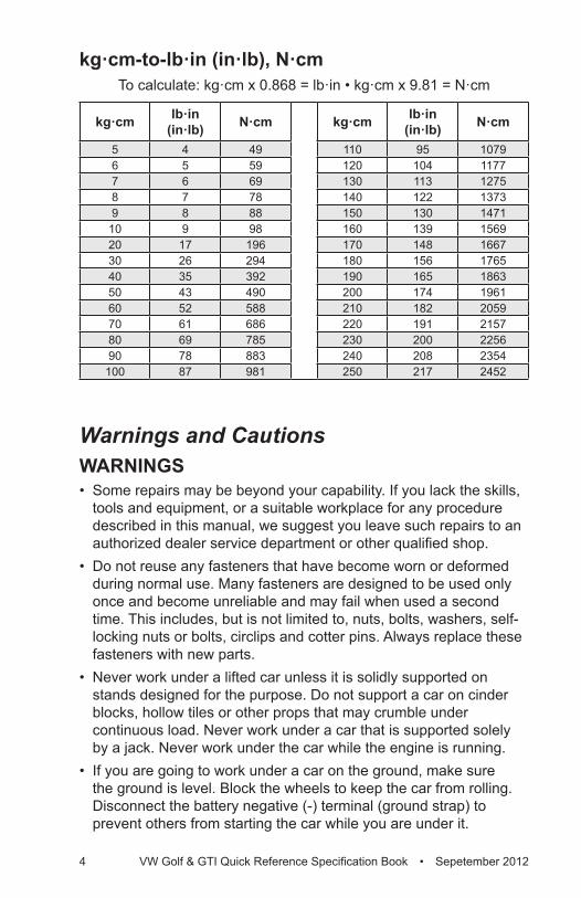
kg·cm-to-lb·in (in·lb), N·cmTo calculate: kg·cm x 0.868 = lb·in • kg·cm x 9.81 = N·cm
kg·cm lb·in (in·lb) N·cm kg·cm lb·in
(in·lb) N·cm
5 4 49 110 95 10796 5 59 120 104 11777 6 69 130 113 12758 7 78 140 122 13739 8 88 150 130 147110 9 98 160 139 156920 17 196 170 148 166730 26 294 180 156 176540 35 392 190 165 186350 43 490 200 174 196160 52 588 210 182 205970 61 686 220 191 215780 69 785 230 200 225690 78 883 240 208 2354100 87 981 250 217 2452
Warnings and CautionsWARNINGS• Some repairs may be beyond your capability. If you lack the skills,
tools and equipment, or a suitable workplace for any procedure described in this manual, we suggest you leave such repairs to an authorized dealer service department or other qualified shop.
• Do not reuse any fasteners that have become worn or deformed during normal use. Many fasteners are designed to be used only once and become unreliable and may fail when used a second time. This includes, but is not limited to, nuts, bolts, washers, self-locking nuts or bolts, circlips and cotter pins. Always replace these fasteners with new parts.
• Never work under a lifted car unless it is solidly supported on stands designed for the purpose. Do not support a car on cinder blocks, hollow tiles or other props that may crumble under continuous load. Never work under a car that is supported solely by a jack. Never work under the car while the engine is running.
• If you are going to work under a car on the ground, make sure the ground is level. Block the wheels to keep the car from rolling. Disconnect the battery negative (-) terminal (ground strap) to prevent others from starting the car while you are under it.
Gen
eral
Info
rmat
ion
VW Golf & GTI Quick Reference Specification Book • September 2012 5
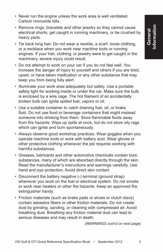
• Never run the engine unless the work area is well ventilated. Carbon monoxide kills.
• Remove rings, bracelets and other jewelry so they cannot cause electrical shorts, get caught in running machinery, or be crushed by heavy parts.
• Tie back long hair. Do not wear a necktie, a scarf, loose clothing, or a necklace when you work near machine tools or running engines. If your hair, clothing, or jewelry were to get caught in the machinery, severe injury could result.
• Do not attempt to work on your car if you do not feel well. You increase the danger of injury to yourself and others if you are tired, upset, or have taken medication or any other substance that may keep you from being fully alert.
• Illuminate your work area adequately but safely. Use a portable safety light for working inside or under the car. Make sure the bulb is enclosed by a wire cage. The hot filament of an accidentally broken bulb can ignite spilled fuel, vapors or oil.
• Use a suitable container to catch draining fuel, oil, or brake fluid. Do not use food or beverage containers that might mislead someone into drinking from them. Store flammable fluids away from fire hazards. Wipe up spills at once, but do not store oily rags which can ignite and burn spontaneously.
• Always observe good workshop practices. Wear goggles when you operate machine tools or work with battery acid. Wear gloves or other protective clothing whenever the job requires working with harmful substances.
• Greases, lubricants and other automotive chemicals contain toxic substances, many of which are absorbed directly through the skin. Read the manufacturer’s instructions and warnings carefully. Use hand and eye protection. Avoid direct skin contact
• Disconnect the battery negative (-) terminal (ground strap) whenever you work on the fuel or electrical system. Do not smoke or work near heaters or other fire hazards. Keep an approved fire extinguisher handy.
• Friction materials (such as brake pads or shoes or clutch discs) contain asbestos fibers or other friction materials. Do not create dust by grinding, sanding, or cleaning with compressed air. Avoid breathing dust. Breathing any friction material dust can lead to serious diseases and may result in death.
(WARNINGS cont’d on next page)
6 VW Golf & GTI Quick Reference Specification Book • Sepetember 2012
WARNINGS (cont’d)• Batteries give off explosive hydrogen gas during charging. Keep
sparks, lighted matches and open flame away from the top of the battery. If hydrogen gas escaping from the cap vents is ignited, it ignites the gas trapped in the cells and causes the battery to explode.
• Connect and disconnect battery cables, jumper cables or a battery charger only with the ignition off. Do not disconnect the battery while the engine is running.
• Do not quick-charge the battery (for boost starting) for longer than one minute. Wait at least one minute before boosting the battery a second time.
• Do not allow battery charging voltage to exceed 16.5 volts. If the battery begins producing gas or boiling violently, reduce the charging rate. Boosting a sulfated battery at a high charging rate can cause an explosion.
• The A/C system is filled with chemical refrigerant, which is hazardous. The A/C system should be serviced only by trained technicians using approved refrigerant recovery/recycling equipment, trained in related safety precautions, and familiar with regulations governing the discharging and disposal of automotive chemical refrigerants.
• Do not expose any part of the A/C system to high temperatures such as open flame. Excessive heat increases system pressure and may cause the system to burst.
• Some aerosol tire inflators are highly flammable. Be extremely cautious when repairing a tire that may have been inflated using an aerosol tire inflator. Keep sparks, open flame or other sources of ignition away from the tire repair area. Inflate and deflate the tire at least four times before breaking the bead from the rim. Completely remove the tire from the rim before attempting any repair.
• Some cars are equipped with a Supplemental Restraint System (SRS) that automatically deploys airbags and pyrotechnic seat belt tensioners in the event of a frontal or side impact. These are explosive devices. Handled improperly or without adequate safeguards, they can be accidentally activated and cause serious injury.
• The ignition system produces high voltages that can be fatal. Avoid contact with exposed terminals and use extreme care when working on a car with the engine running or the ignition on.
Gen
eral
Info
rmat
ion
VW Golf & GTI Quick Reference Specification Book • September 2012 7
• Place jack stands only at locations specified by manufacturer. The vehicle lifting jack supplied with the vehicle is intended for tire changes only. Use a heavy duty floor jack to lift the vehicle before installing jack stands.
• Battery acid (electrolyte) can cause severe burns. Flush contact area with water, seek medical attention.
• Aerosol cleaners and solvents may contain hazardous or deadly vapors and are highly flammable. Use only in a well ventilated area. Do not use on hot surfaces (such as engines or brakes).
• Do not remove coolant reservoir or radiator cap with the engine hot. Burns and engine damage may occur.
CAUTIONS• If you lack the skills, tools and equipment, or a suitable workshop
for any procedure described in this manual, we suggest you leave such repairs to an authorized dealer or other qualified shop.
• Before starting a job, make certain that you have all the necessary tools and parts on hand. Read all the instructions thoroughly and do not attempt shortcuts. Use tools appropriate to the work and use only replacement parts meeting original specifications. Makeshift tools, parts and procedures will not make good repairs.
• Use pneumatic and electric tools only to loosen threaded parts and fasteners. Never use these tools to tighten fasteners, especially on light alloy parts. Always use a torque wrench to tighten fasteners to the tightening torque specification listed.
• Be mindful of the environment and ecology. Before you drain the crankcase, find out the proper way to dispose of the oil. Do not pour oil onto the ground, down a drain, or into a stream, pond or lake. Dispose of in accordance with Federal, State and Local laws.
• The control module for the Anti-lock Brake System (ABS) cannot withstand temperatures from a paint-drying booth or a heat lamp in excess of 95 °C (203 °F) and should not be subjected to temperatures exceeding 85 °C (185 °F) for more than two hours.
• Before doing any electrical welding on cars equipped with ABS, disconnect the battery negative (-) terminal (ground strap) and the ABS control module connector.
• Always make sure the ignition is off before disconnecting battery. (CAUTIONS cont’d on next page)
8 VW Golf & GTI Quick Reference Specification Book • Sepetember 2012
CAUTIONS (cont’d)• Label battery cables before disconnecting. On some models,
battery cables are not color coded. • Disconnecting the battery may erase fault code(s) stored in control
module memory. Check for fault codes prior to disconnecting the battery cables.
• If a normal or rapid charger is used to charge the battery, disconnect the battery and remove it from the vehicle to avoid damaging paint and upholstery.
• Do not quick-charge the battery (for boost starting) for longer than one minute. Wait at least one minute before boosting the battery a second time.
• Connect and disconnect a battery charger only with the battery charger switched off.
• Sealed or “maintenance free” batteries should be slow-charged only, at an amperage rate that is approximately 10% of the battery’s ampere-hour (Ah) rating.
• Do not allow battery charging voltage to exceed 16.5 volts. If the battery begins producing gas or boiling violently, reduce the charging rate. Boosting a sulfated battery at a high charging rate can cause an explosion.
Vehi
cle
Identifi
catio
n
VW Golf & GTI Quick Reference Specification Book • September 2012 9
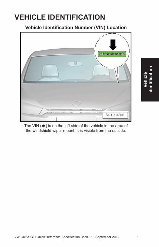
VEHICLE IDENTIFICATIONVehicle Identification Number (VIN) Location
The VIN (Æ) is on the left side of the vehicle in the area of the windshield wiper mount. It is visible from the outside.
10 VW Golf & GTI Quick Reference Specification Book • September 2012
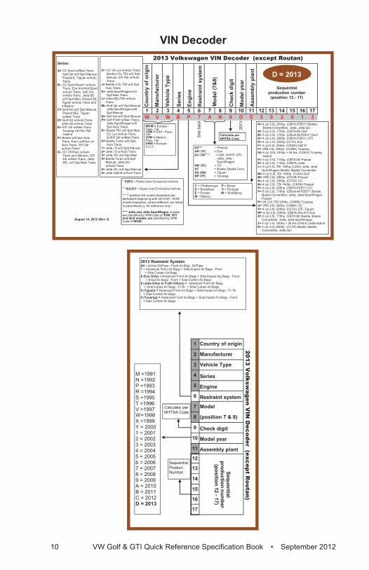
VIN Decoder2013 Volkswagen VIN Decoder (except Routan)
Cou
ntry
of o
rigin
Man
ufac
ture
r
Vehi
cle
Type
Serie
s
Engi
ne
Res
trai
nt s
yste
m
Che
ck d
igit
Mod
el y
ear
Ass
embl
y pl
ant
1 2 3 4 5 6 7 8 9 10 11 12 13 14 15 16 17W V W B P 7 A N 8 D E 5 0 2 0 1 3
See
bac
k
2013
August 14, 2012 (Rev 3)
2013 Volkswagen VIN Decoder (except Routan)
Cou
ntry
of o
rigin
Man
ufac
ture
r
Vehi
cle
Type
Serie
s
Engi
ne
Res
trai
nt s
yste
m
Mod
el
(pos
ition
7 &
8)
Che
ck d
igit
Mod
el y
ear
Ass
embl
y pl
ant
1 2 3 4 5 6 7 8 9 10 11 12 13 14 15 16 17
Mod
el (7
&8)
Sequentialproduction number
(position 12 - 17)
Series:
A= CC Sport w/Man Trans,Golf 2dr w/5 Spd Manual, Passat S, Tiguan w/Auto Trans
B= CC Sport/Sport+ w/Auto Trans, Eos Komfort/Sport w/Auto Trans, Golf 2dr w/Auto Trans, Jetta SE w/5 Spd Man, Passat SE,
Tiguan w/Auto Trans and 4-Motion
C= Golf 4dr w/5 Spd Manual, Passat SEL, Tiguan w/Man Trans
D= Golf 4dr w/Auto Trans, Jetta SE w/Auto Trans
E= GTI 2dr w/Man Trans, Touareg V6 FSI /TDI /Hybrid
F= Beetle w/6 Spd Auto Trans, Eos Lux/Exec w/ Auto Trans, GTI 2dr w/Auto Trans
G= CC V6 Exec w/Auto Trans and 4Motion, GTI 4dr w/Man Trans, Jetta SEL w/5 Spd Man Trans
A= 4 cyl 2.0L 200hp (CBFA-PZEV*) Beetle, Beetle Convertible, Jetta, Jetta GLI
A= 5 cyl 2.5L 170hp (CBTA-M) GolfB= 5 cyl 2.5L 170hp (CBUA-M-PZEV*) GolfD= 4 cyl 2.0L 200hp (CBFA-PZEV*) GTID= 4 cyl 2.0L 200hp (CCTA) EosF= 4 cyl 2.0L 256hp (CRZA) Golf RF= VR6 3.6L 280hp (CGRA) TouaregG= 6 cyl 3.0L 333hp + 34 Kw (CGFA) Touareg
HybridH= 5 cyl 2.5L 170hp (CBTA-M) PassatK= 4 cyl 2.0L 115hp (CBPA) JettaL= 4 cyl 2.0L TDI 140hp (CJAA) Jetta, Jetta
SportWagen, Beetle, Beetle ConvertibleM= 4 cyl 2.0L TDI 140hp (CJAA) GolfM= VR6 3.6L 280hp (CDVB) PassatN= 4 cyl 2.0L 200hp (CCTA) CC N= 4 cyl 2.0L TDI 140hp (CKRA) PassatP= 4 cyl 2.0L 200hp (CBFA-PZEV*) CCP= 5 cyl 2.5L 170hp (CBUA-M-PZEV*) Beetle,
Beetle Convertible, Jetta, Jetta SportWagen, Passat
P= V6 3.0L TDI 240hp (CNRB) TouaregU= VR6 3.6L 280hp (CNNA) CCV= 4 cyl 2.0L 200hp (CCTA) GTI, TiguanW= 4 cyl 2.0L 200hp (CBFA-SULEV) EosX= 5 cyl 2.5L 170hp (CBTA-M) Beetle, Beetle
Convertible, Jetta, Jetta SportWagen3= 4 cyl 1.4L 150hp + 28 Kw (CNLA) Jetta Hybrid6= 4 cyl 2.0L 200hp (CCTA) Beetle, Beetle
Convertible, Jetta GLI
* PZEV = Partial Zero Emissions Vehicle
** SULEV = Super Low Emissions Vehicle
*** 7 position US model characters are alphabetic beginning with 2010 MY. ROW model characters, where different, are listed in parenthesis (), for reference only.
**** Jetta and Jetta SportWagen models are identified by WMI code of 3VW. GTI and Golf models are identified by WMI code of WVW.
A3*** = PassatAH (1F) = Eos AJ (16)**** = Golf, Golf R, GTI,
Jetta, JettaSportWagen
AN (3C) = CC AT = Beetle, Beetle Conv.AX (5N) = TiguanBP (7P) = Touareg
Sequentialproduction number
(position 12 - 17)
M =
1991
N =
1992
P =
1993
R =
1994
S =
1995
T =1
996
V =
1997
W=1
998
X =1
999
Y =
200
01
= 20
012
= 20
023
= 20
034
= 20
045
= 20
056
= 20
067
= 20
078
= 20
089
= 20
09A
= 2
010
B =
201
1C
= 2
012
D =
201
3
2013
Res
trai
nt S
yste
m:
All =
Act
ive-
Dr/P
ass
-Fro
nt A
ir B
ag -
Dr/P
ass
7 =
Adv
ance
d Fr
ont A
ir B
ags
+S
ide
Impa
ct A
ir B
ags
-Fro
nt
+ S
ide
Cur
tain
Air
Bag
s8
(Eos
Onl
y) =
Adv
ance
d Fr
ont A
ir B
ags
+ S
ide
Impa
ct A
ig B
ags
-Fro
nt
+ K
nee
Air
Bag
s -F
ront
+ S
ide
Cur
tain
Air
Bag
s8
(Jet
ta O
nly)
or 9
(All
Oth
ers)
= A
dvan
ced
Fron
t Air
Bag
s +
Sid
e Im
pact
Air
Bag
s -F
r.Rr.
+ S
ide
Cur
tain
Air
Bag
s9
(Tig
uan)
= A
dvan
ced
Fron
t Air
Bag
s +
Sid
e Im
pact
Air
Bag
s -F
r. R
r. +
Sid
e C
urta
in A
ir B
ags
9 (T
ouar
eg) =
Adv
ance
d Fr
ont A
ir B
ags
+ S
ide
Impa
ct A
ir B
ags
-Fro
nt
+ S
ide
Cur
tain
Air
Bag
s
Cal
cula
te p
er
NH
TSA
Cod
e
Seq
uent
ial
Pro
duct
Num
ber
Calculate perNHTSA Code
D = 2013
WVW = Europe -Pass. Car1VW = USA - Pass. Car3VW = Mexico -Pass. CarVWG = Europe -S.U.V.
H= CC V6 Lux w/Auto Trans, Beetle 2.5L TDI w/5 Spd Manual, GTI 4dr w/Auto Trans
J= Beetle 2.5L TDI w/6 Spd Auto Trans
K= Jetta SportWagen w/5 Spd Man Trans
L= Jetta SEL/TDI w/Auto Trans
M= Golf 2dr w/6 Spd Manual, Jetta SportWagen w/6 Spd Manual
N= Golf 4dr w/6 Spd ManualP= Golf R 4dr w/Man Trans,
Jetta SportWagen w/6 Spd Auto Trans
R= Beetle TDI w/6 Spd Man, CC Lux w/Auto Trans, Golf R 2dr w/Man Trans
V= Beetle Turbo w/6 Spd Auto Trans
1= Jetta / S w/5 Spd Manual2= Jetta / S w/Auto Trans 3= Jetta TDI w/6 Spd Man4= Beetle Turbo w/6 Spd
Manual, Jetta GLI w/Auto Trans
5= Jetta GLI w/6 Spd Manual6= Jetta Hybrid w/Auto Trans
C = Chattanooga P = MoselD = Bratislava V = Portugal E = Emden W = WolfsburgM = Mexico
2013 Volksw
agen VIN
Decoder (except R
outan)
Country of origin
Manufacturer
Vehicle Type
Series
Engine
Restraint system
Check digit
Model year
Assembly plant
12
34
56
78
910
1112
1314
1516
17W
VW
BP
7A
N8
DE
50
20
13
See back
2013
August 14, 2012 (Rev 3)
2013 Volksw
agen VIN
Decoder (except R
outan)
Country of origin
Manufacturer
Vehicle Type
Series
Engine
Restraint system
Model
(position 7 & 8)
Check digit
Model year
Assembly plant
1
2
3
4
5
6
7
8
9
10
11
12
13
14
15
16
17
Model (7&8)
Sequentialproduction num
ber(position 12 -17)
Series:
A=C
C S
port w/M
an Trans,G
olf 2dr w/5 S
pd Manual,
Passat S
, Tiguan w/A
uto Trans
B= C
C S
port/Sport+ w
/Auto
Trans, Eos K
omfort/S
port w
/Auto Trans, G
olf 2dr w
/Auto Trans, Jetta S
E
w/5 S
pd Man, P
assat SE
, Tiguan w
/Auto Trans and
4-Motion
C= G
olf 4dr w/5 S
pd Manual,
Passat S
EL, Tiguan
w/M
an TransD
= Golf 4dr w
/Auto Trans,
Jetta SE
w/A
uto TransE= G
TI 2dr w/M
an Trans, Touareg V
6 FSI /TD
I /H
ybrid F= B
eetle w/6 S
pd Auto
Trans, Eos Lux/E
xec w/
Auto Trans, G
TI 2dr w
/Auto Trans
G= C
C V
6 Exec w
/Auto
Trans and 4Motion, G
TI 4dr w
/Man Trans, Jetta
SE
L w/5 S
pd Man Trans
A= 4 cyl 2.0L 200hp (CB
FA-P
ZEV
*) Beetle,
Beetle C
onvertible, Jetta, Jetta GLI
A=5 cyl 2.5L 170hp (C
BTA
-M) G
olfB
= 5 cyl 2.5L 170hp (CB
UA
-M-P
ZEV
*) Golf
D= 4 cyl 2.0L 200hp (C
BFA
-PZE
V*) G
TID
= 4 cyl 2.0L 200hp (CC
TA) E
osF= 4 cyl 2.0L 256hp (C
RZA
) Golf R
F= VR
6 3.6L 280hp (CG
RA
) TouaregG
= 6 cyl 3.0L 333hp + 34 Kw
(CG
FA) Touareg
Hybrid
H= 5 cyl 2.5L 170hp (C
BTA
-M) P
assatK
= 4 cyl 2.0L 115hp (CB
PA
) JettaL= 4 cyl 2.0L TD
I 140hp (CJA
A) Jetta, Jetta
SportW
agen, Beetle, B
eetle Convertible
M= 4 cyl 2.0L TD
I 140hp (CJA
A) G
olfM
= VR
6 3.6L 280hp (CD
VB
) Passat
N=
4 cyl 2.0L 200hp (CC
TA) C
C
N= 4 cyl 2.0L TD
I 140hp (CK
RA
) Passat
P=4 cyl 2.0L 200hp (C
BFA
-PZE
V*) C
CP= 5 cyl 2.5L 170hp (C
BU
A-M
-PZE
V*) B
eetle,B
eetle Convertible, Jetta, Jetta S
portWagen,
Passat
P= V6 3.0L TD
I 240hp (CN
RB
) TouaregU
=V
R6 3.6L 280hp (C
NN
A) C
CV= 4 cyl 2.0L 200hp (C
CTA
) GTI, Tiguan
W= 4 cyl 2.0L 200hp (C
BFA
-SU
LEV
) Eos
X= 5 cyl 2.5L 170hp (CB
TA-M
)B
eetle, Beetle
Convertible, Jetta, Jetta S
portWagen
3= 4 cyl 1.4L 150hp + 28 Kw
(CN
LA) Jetta H
ybrid6= 4 cyl 2.0L 200hp (C
CTA
) Beetle, B
eetleC
onvertible, Jetta GLI
* PZEV= P
artial Zero Em
issions Vehicle
** SULEV
= Super Low
Em
issions Vehicle
*** 7 position US
model characters are
alphabetic beginning with 2010 M
Y. RO
W
model characters, w
here different, are listed in parenthesis (), for reference only.
**** Jetta and Jetta SportWagen m
odels are identified by W
MI code of 3VW
. GTI
and Golf m
odels are identified by WM
I code of W
VW.
A3*** = Passat
AH (1F)
= Eos
AJ (16)**** = Golf, G
olf R, G
TI, Jetta, JettaS
portWagen
AN(3C
) = CC
AT = B
eetle, Beetle C
onv.AX (5N
) = TiguanB
P (7P) = Touareg
Sequentialproduction num
ber(position 12 -17)
M =1991N =1992P =1993R =1994S =1995T =1996V =1997W=1998X =1999Y = 20001 = 20012 = 20023 = 20034 = 20045 = 20056 = 20067 = 20078 = 20089 = 2009A = 2010B = 2011C = 2012D = 2013
2013 Restraint System:All = Active-Dr/Pass - Front Air Bag - Dr/Pass 7 = Advanced Front Air Bags + Side Impact Air Bags - Front
+ Side Curtain Air Bags8 (Eos Only) = Advanced Front Air Bags + Side Impact Aig Bags - Front
+ Knee Air Bags - Front + Side Curtain Air Bags8 (Jetta Only) or 9 (All Others) = Advanced Front Air Bags
+ Side Impact Air Bags - Fr.Rr. + Side Curtain Air Bags9 (Tiguan) = Advanced Front Air Bags + Side Impact Air Bags - Fr. Rr.
+ Side Curtain Air Bags9 (Touareg) = Advanced Front Air Bags + Side Impact Air Bags - Front
+ Side Curtain Air Bags
Calculate per NHTSA Code
SequentialProductNumber
Calculate per
NH
TSA Code
D = 2013
WVW
= Europe -
Pass. C
ar1VW
=U
SA
-Pass.
Car
3VW = M
exico -P
ass. Car
VWG
= Europe -
S.U
.V.
H= C
C V
6 Lux w/A
uto Trans, B
eetle 2.5L TDI w
/5 Spd
Manual, G
TI 4dr w/A
uto Trans
J= Beetle 2.5L TD
I w/6 S
pd A
uto TransK
= Jetta SportW
agen w/5
Spd M
an TransL= Jetta S
EL/TD
I w/A
uto Trans
M= G
olf 2dr w/6 S
pd Manual,
Jetta SportW
agen w/6
Spd M
anualN
= Golf 4dr w
/6 Spd M
anualP= G
olf R 4dr w
/Man Trans,
Jetta SportW
agen w/6
Spd A
uto TransR
= Beetle TD
I w/6 S
pd Man,
CC
Lux w/A
uto Trans, G
olf R 2dr w
/Man Trans
V= Beetle Turbo w
/6 Spd
Auto Trans
1= Jetta / S w
/5 Spd M
anual2= Jetta / S
w/A
uto Trans 3= Jetta TD
I w/6 S
pd Man
4= Beetle Turbo w
/6 Spd
Manual, Jetta G
LI w
/Auto Trans
5= Jetta GLI w
/6 Spd M
anual6= Jetta H
ybrid w/A
uto Trans
C = C
hattanooga P= M
oselD
= Bratislava V
= Portugal
E= E
mden W
= Wolfsburg
M = M
exico
Vehi
cle
Identifi
catio
n
VW Golf & GTI Quick Reference Specification Book • September 2012 11
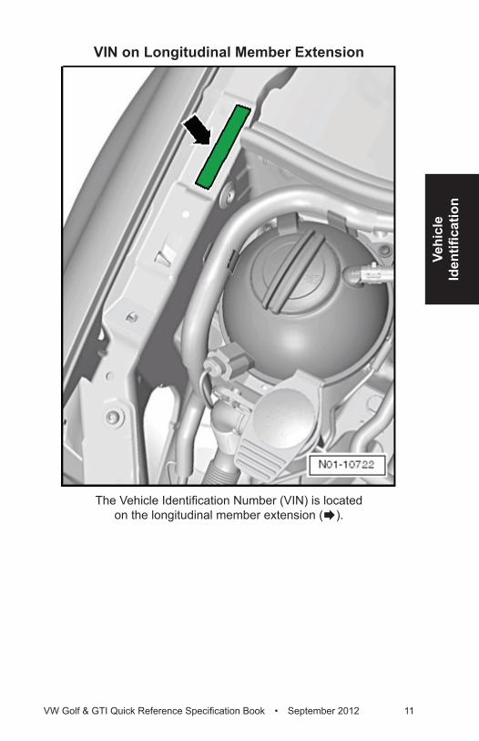
VIN on Longitudinal Member Extension
The Vehicle Identification Number (VIN) is located on the longitudinal member extension (Æ).
12 VW Golf & GTI Quick Reference Specification Book • September 2012
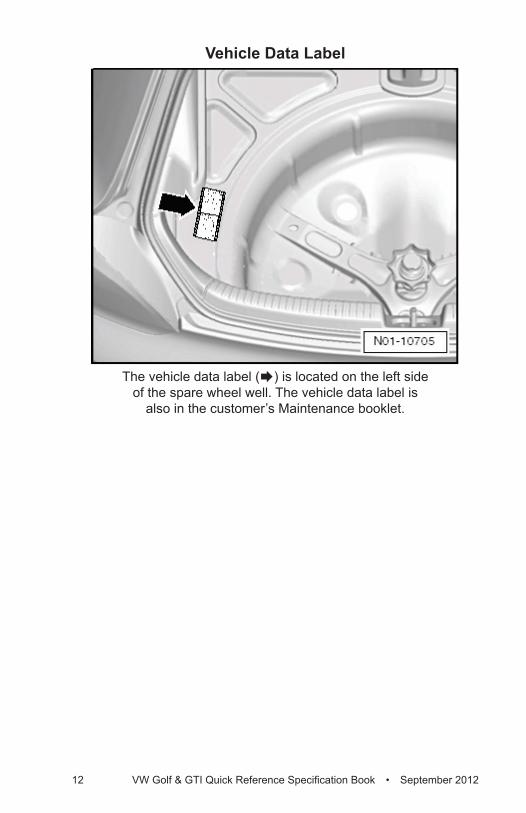
Vehicle Data Label
The vehicle data label (Æ) is located on the left side of the spare wheel well. The vehicle data label is
also in the customer’s Maintenance booklet.
Sale
sC
odes
VW Golf & GTI Quick Reference Specification Book • September 2012 13
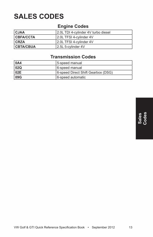
SALES CODESEngine Codes
CJAA 2.0L TDI 4-cylinder 4V turbo dieselCBFA/CCTA 2.0L TFSI 4-cylinder 4VCRZA 2.0L TFSI 4-cylinder 4VCBTA/CBUA 2.5L 5-cylinder 4V
Transmission Codes0A4 5-speed manual02Q 6-speed manual02E 6-speed Direct Shift Gearbox (DSG)09G 6-speed automatic
14 VW Golf & GTI Quick Reference Specification Book • September 2012
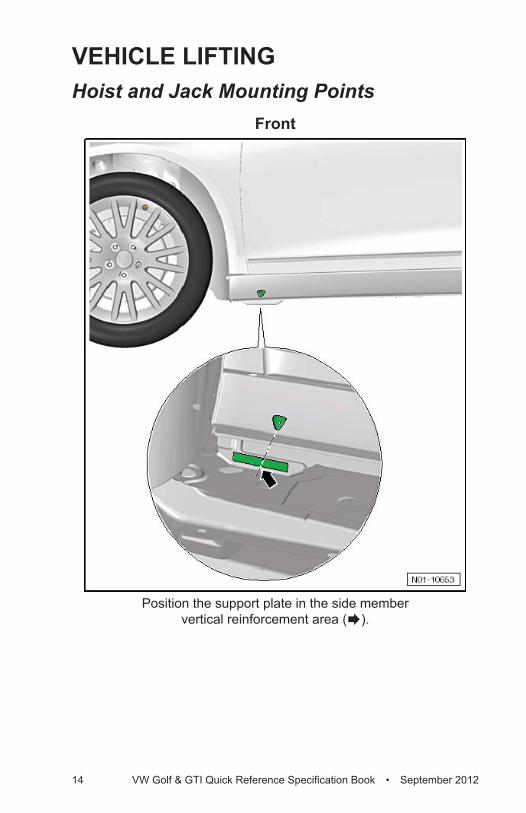
VEHICLE LIFTINGHoist and Jack Mounting Points
Front
Position the support plate in the side member vertical reinforcement area (Æ).
Vehi
cle
Lifti
ng
VW Golf & GTI Quick Reference Specification Book • September 2012 15
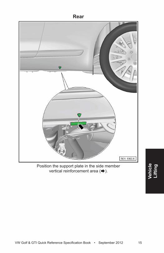
Rear
Position the support plate in the side member vertical reinforcement area (Æ).
16 VW Golf & GTI Quick Reference Specification Book • September 2012
ENGINE MECHANICAL – 2.0L CJAA (TDI)General, Technical Data
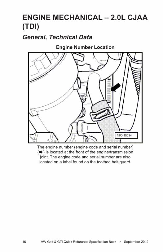
Engine Number Location
The engine number (engine code and serial number) (Æ) is located at the front of the engine/transmission
joint. The engine code and serial number are also located on a label found on the toothed belt guard.
Engi
ne –
2.
0L C
JAA
(TD
I)
VW Golf & GTI Quick Reference Specification Book • September 2012 17
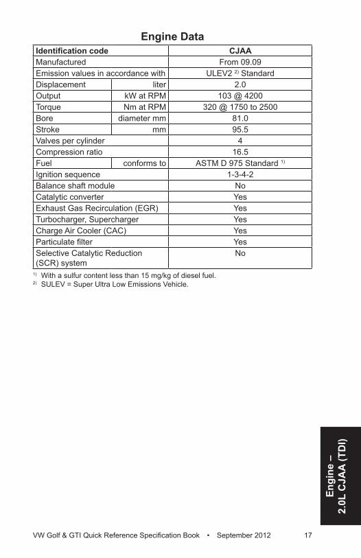
Engine DataIdentification code CJAAManufactured From 09.09Emission values in accordance with ULEV2 2) StandardDisplacement liter 2.0Output kW at RPM 103 @ 4200Torque Nm at RPM 320 @ 1750 to 2500Bore diameter mm 81.0Stroke mm 95.5Valves per cylinder 4Compression ratio 16.5Fuel conforms to ASTM D 975 Standard 1)
Ignition sequence 1-3-4-2Balance shaft module NoCatalytic converter YesExhaust Gas Recirculation (EGR) YesTurbocharger, Supercharger YesCharge Air Cooler (CAC) YesParticulate filter YesSelective Catalytic Reduction (SCR) system
No
1) With a sulfur content less than 15 mg/kg of diesel fuel.2) SULEV = Super Ultra Low Emissions Vehicle.
18 VW Golf & GTI Quick Reference Specification Book • September 2012
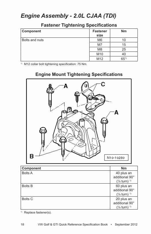
Engine Assembly - 2.0L CJAA (TDI)Fastener Tightening Specifications
Component Fastener size
Nm
Bolts and nuts M6 10M7 15M8 25
M10 40M12 651)
1) M12 collar bolt tightening specification: 75 Nm.
Engine Mount Tightening Specifications
Component NmBolts A 40 plus an
additional 90° (¼ turn) 1)
Bolts B 60 plus an additional 90°
(¼ turn) 1)
Bolts C 20 plus an additional 90°
(¼ turn) 1)
1) Replace fastener(s).
Engi
ne –
2.
0L C
JAA
(TD
I)
VW Golf & GTI Quick Reference Specification Book • September 2012 19
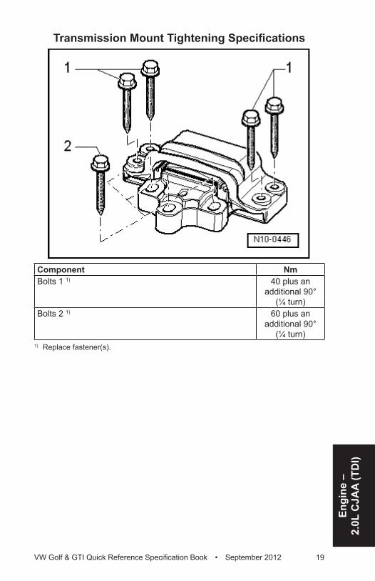
Transmission Mount Tightening Specifications
Component NmBolts 1 1) 40 plus an
additional 90° (¼ turn)
Bolts 2 1) 60 plus an additional 90°
(¼ turn) 1) Replace fastener(s).
20 VW Golf & GTI Quick Reference Specification Book • September 2012
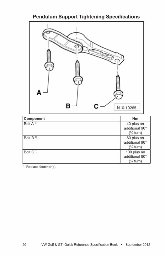
Pendulum Support Tightening Specifications
Component NmBolt A 1) 40 plus an
additional 90° (¼ turn)
Bolt B 1) 60 plus an additional 90°
(¼ turn)Bolt C 1) 100 plus an
additional 90° (¼ turn)
1) Replace fastener(s).
Engi
ne –
2.
0L C
JAA
(TD
I)
VW Golf & GTI Quick Reference Specification Book • September 2012 21
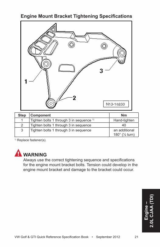
Engine Mount Bracket Tightening Specifications
Step Component Nm1 Tighten bolts 1 through 3 in sequence 1) Hand-tighten2 Tighten bolts 1 through 3 in sequence 403 Tighten bolts 1 through 3 in sequence an additional
180° (½ turn)1) Replace fastener(s).
! WARNINGAlways use the correct tightening sequence and specifications for the engine mount bracket bolts. Tension could develop in the engine mount bracket and damage to the bracket could occur.

22 VW Golf & GTI Quick Reference Specification Book • September 2012
Crankshaft, Cylinder Block – 2.0L CJAA (TDI)
Fastener Tightening SpecificationsComponent NmAir conditioning compressor-to-accessory bracket bolt 25Bracket-to-oil filter bracket bolt 10Camshaft sprocket-to-camshaft bolt 20 plus an
additional 45° (⅛ turn)
Center toothed belt guard-to-lower toothed belt guard bolt 1)
10
Connecting piece-to-cylinder block bolt 15Connecting rod cap-to-connecting rod bolt 1) 4) 30 plus an
additional 90° (¼ turn)
Coolant pump-to-cylinder block bolt 15Crankshaft bearing cap-to-cylinder block bolt 1) 65 plus an
additional 90° (¼ turn)
Crankshaft toothed belt gear-to-crankshaft bolt 1) 120 plus an additional 90°
(¼ turn)Engine speed sensor-to-cylinder block bolt 5Flywheel-to-crankshaft bolt 1) 60 plus an
additional 90° (¼ turn)
Generator-to-accessory bracket bolt 25High pressure pump-to-accessory bracket bolt 20 plus an
additional 90° (¼ turn)
High pressure pump toothed belt gear-to-hub bolt 1) 20 plus an additional 90°
(¼ turn)Hub-to-camshaft bolt 100Hub-to-high pressure pump nut 95Idler pulley-to-accessory bracket bolt 50 plus an
additional 90° (¼ turn)
Idler roller-to-accessory bracket bolt 15Oil filter bracket-to-cylinder block bolt 1) 3) 15 plus an
additional 90° (¼ turn)
Oil pan-to-cylinder block bolt 15Oil spray jet-to-cylinder block bolt 25
Engi
ne –
2.
0L C
JAA
(TD
I)
VW Golf & GTI Quick Reference Specification Book • September 2012 23
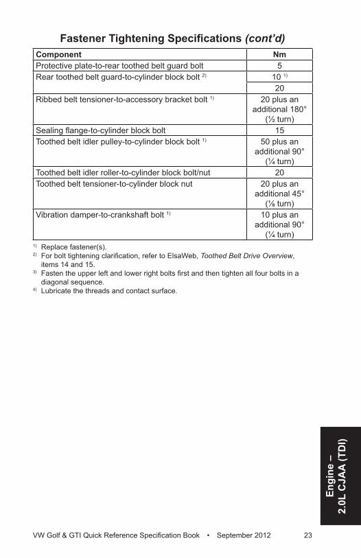
Component NmProtective plate-to-rear toothed belt guard bolt 5Rear toothed belt guard-to-cylinder block bolt 2) 10 1)
20Ribbed belt tensioner-to-accessory bracket bolt 1) 20 plus an
additional 180° (½ turn)
Sealing flange-to-cylinder block bolt 15Toothed belt idler pulley-to-cylinder block bolt 1) 50 plus an
additional 90° (¼ turn)
Toothed belt idler roller-to-cylinder block bolt/nut 20Toothed belt tensioner-to-cylinder block nut 20 plus an
additional 45° (⅛ turn)
Vibration damper-to-crankshaft bolt 1) 10 plus an additional 90°
(¼ turn)1) Replace fastener(s).2) For bolt tightening clarification, refer to ElsaWeb, Toothed Belt Drive Overview,
items 14 and 15.3) Fasten the upper left and lower right bolts first and then tighten all four bolts in a
diagonal sequence.4) Lubricate the threads and contact surface.
Fastener Tightening Specifications (cont’d)
24 VW Golf & GTI Quick Reference Specification Book • September 2012
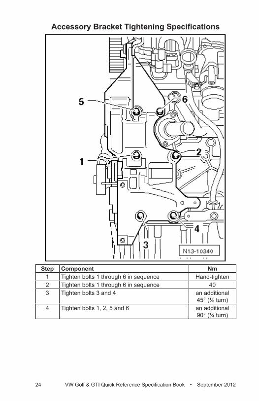
Accessory Bracket Tightening Specifications
Step Component Nm1 Tighten bolts 1 through 6 in sequence Hand-tighten2 Tighten bolts 1 through 6 in sequence 403 Tighten bolts 3 and 4 an additional
45° (⅛ turn)4 Tighten bolts 1, 2, 5 and 6 an additional
90° (¼ turn)
Engi
ne –
2.
0L C
JAA
(TD
I)
VW Golf & GTI Quick Reference Specification Book • September 2012 25
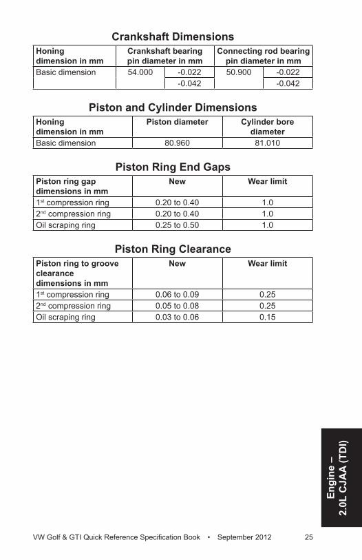
Crankshaft DimensionsHoning dimension in mm
Crankshaft bearing pin diameter in mm
Connecting rod bearing pin diameter in mm
Basic dimension 54.000 -0.022 50.900 -0.022-0.042 -0.042
Piston and Cylinder DimensionsHoning dimension in mm
Piston diameter Cylinder bore diameter
Basic dimension 80.960 81.010
Piston Ring End GapsPiston ring gap dimensions in mm
New Wear limit
1st compression ring 0.20 to 0.40 1.02nd compression ring 0.20 to 0.40 1.0Oil scraping ring 0.25 to 0.50 1.0
Piston Ring ClearancePiston ring to groove clearance dimensions in mm
New Wear limit
1st compression ring 0.06 to 0.09 0.252nd compression ring 0.05 to 0.08 0.25Oil scraping ring 0.03 to 0.06 0.15

26 VW Golf & GTI Quick Reference Specification Book • September 2012
Cylinder Head, Valvetrain – 2.0L CJAA (TDI)
Fastener Tightening SpecificationsComponent NmAdapter to cylinder head bolt 10Camshaft Position (CMP) sensor-to-cylinder head bolt 10Camshaft sprocket-to-camshaft bolt 20 plus an
additional 90° (¼ turn)
Center toothed belt guard to lower toothed belt guard bolt 1)
10
Coolant pump to cylinder block bolt 15Crankshaft toothed belt gear to crankshaft bolt 1) 120 plus an
additional 90° (¼ turn)
Engine mount bracket to cylinder block bolt 1) 40 plus an additional 180°
(½ turn)Fuel rail-to-cylinder head cover bolt 22Heat shield-to-cylinder head cover bolt 5High pressure pump toothed belt gear-to-hub bolt 1) 20 plus an
additional 90° (¼ turn)
Hub-to-camshaft bolt 100Lifting eye-to-cylinder head bolt/stud bolt 25Protective plate to rear toothed belt guard bolt 5Rear toothed belt guard to cylinder block bolt 2) 10 1)
20Sealing cap-to-cylinder head cover bolt 5Tensioning plate-to-cylinder head cover nut 10Toothed belt idler pulley to cylinder block bolt 1) 50 plus an
additional 90° (¼ turn)
Toothed belt idler roller to cylinder block bolt/nut 20Toothed belt tensioner-to-cylinder block nut 20 plus an
additional 45° (⅛ turn)
Vacuum pump-to-cylinder head bolt 10Vibration damper-to-crankshaft bolt 1) 10 plus an
additional 90° (¼ turn)
1) Replace fastener(s).2) For bolt tightening clarification, refer to ElsaWeb, Toothed Belt Overview, items 14
and 15.
Engi
ne –
2.
0L C
JAA
(TD
I)
VW Golf & GTI Quick Reference Specification Book • September 2012 27
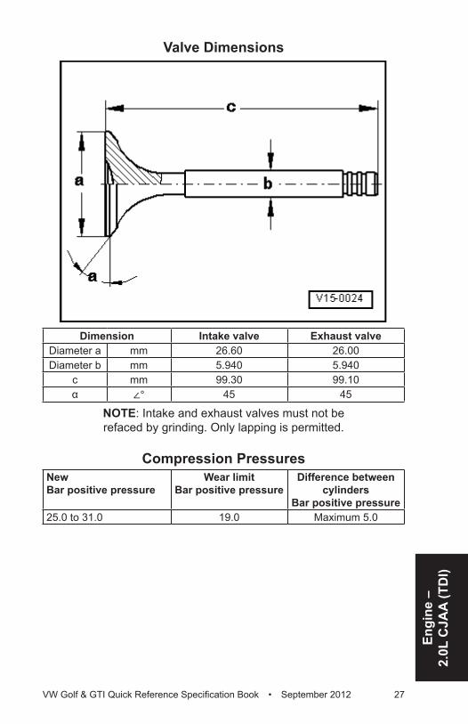
Valve Dimensions
Dimension Intake valve Exhaust valveDiameter a mm 26.60 26.00Diameter b mm 5.940 5.940
c mm 99.30 99.10α ∠° 45 45
NOTE: Intake and exhaust valves must not be refaced by grinding. Only lapping is permitted.
Compression PressuresNewBar positive pressure
Wear limitBar positive pressure
Difference between cylinders
Bar positive pressure25.0 to 31.0 19.0 Maximum 5.0
28 VW Golf & GTI Quick Reference Specification Book • September 2012
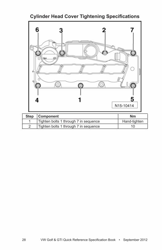
Cylinder Head Cover Tightening Specifications
Step Component Nm1 Tighten bolts 1 through 7 in sequence Hand-tighten2 Tighten bolts 1 through 7 in sequence 10
Engi
ne –
2.
0L C
JAA
(TD
I)
VW Golf & GTI Quick Reference Specification Book • September 2012 29
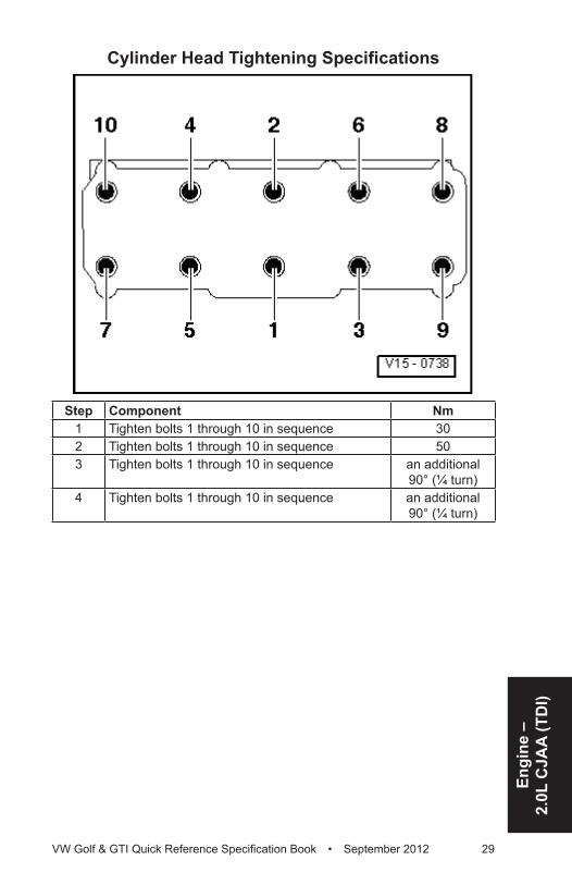
Cylinder Head Tightening Specifications
Step Component Nm1 Tighten bolts 1 through 10 in sequence 302 Tighten bolts 1 through 10 in sequence 503 Tighten bolts 1 through 10 in sequence an additional
90° (¼ turn)4 Tighten bolts 1 through 10 in sequence an additional
90° (¼ turn)
30 VW Golf & GTI Quick Reference Specification Book • September 2012
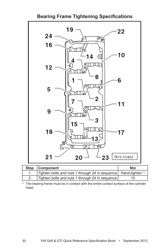
Bearing Frame Tightening Specifications
Step Component Nm1 Tighten bolts and nuts 1 through 24 in sequence Hand-tighten 1)
2 Tighten bolts and nuts 1 through 24 in sequence 101) The bearing frame must be in contact with the entire contact surface of the cylinder
head.
Engi
ne –
2.
0L C
JAA
(TD
I)
VW Golf & GTI Quick Reference Specification Book • September 2012 31
Lubrication – 2.0L CJAA (TDI)Fastener Tightening Specifications
Component NmChain tensioner with tensioning rail-to-cylinder block bolt 15Oil filter bracket cap 25Oil filter bracket connection 30Oil filter bracket cover 25Oil filter bracket-to-cylinder block bolt 1) 2) 15 plus an
additional 90° (¼ turn)
Oil level thermal sensor-to-oil pan bolt 10Oil pan drain plug 1) 30Oil pan-to-cylinder block bolt 15Oil pan-to-transmission bolt 40Oil pressure switch-to-oil filter bracket 22Oil pump sprocket-to-oil pump bolt 20 plus an
additional 90° (¼ turn)
Oil spray jet-to-cylinder block bolt 25Oil supply line clamp bolt 10Oil supply line fitting-to-connection 22Oil supply line fitting-to-turbocharger 22Sealing flange-to-cylinder block bolt 15Suction pipe-to-oil pump bolt 15Windage tray-to-cylinder block bolt 15Wiring harness bracket-to-oil filter bracket bolt 10
1) Replace fastener(s).2) Tighten the upper left and lower right bolts first and then tighten all four bolts in a
diagonal sequence.
32 VW Golf & GTI Quick Reference Specification Book • September 2012
Cooling System – 2.0L CJAA (TDI)Fastener Tightening Specifications
Component Nm4/2 way valve with thermostat-to-cylinder block bolt 15Coolant expansion tank to body stud bolt 5Coolant fan shroud nut 5Coolant pump-to-cylinder block bolt 15Coolant reservoir-to-body stud bolt 3Cylinder block connecting piece bolt 15Engine pre-heater coolant pipe/engine pre-heater bracket to cylinder block bolt
10
Radiator fan shroud bolt 5Radiator bolt 5Ventilation pipe-to-intake manifold bolt 10
Fuel Supply – 2.0L CJAA (TDI)Fastener Tightening Specifications
Component NmAccelerator pedal module-to-body bolt 10Exhaust pressure sensor 1 bracket bolt 8Fuel filler door unit-to-body bolt 1.5Fuel filler tube-to-body bolt 10Fuel filter cover-to-fuel filter housing bolt (Version A) 8Fuel filter cover-to-fuel filter housing bolt (Version B) 5Fuel filter housing-to-body bolt/nut 10Fuel tank securing strap-to-body bolt 1) 25Fuel tank-to-body bolt 1) 25Fuel tank locking ring 110
1) Replace fastener(s).
Engi
ne –
2.
0L C
JAA
(TD
I)
VW Golf & GTI Quick Reference Specification Book • September 2012 33
Turbocharger – 2.0L CJAA (TDI)Fastener Tightening Specifications
Component NmAdapter-to-connecting piece bolt 8Charge Air Cooler (CAC) mount bolt 5Charge air pipe-to-cylinder block bolt 8Charge air pipe-to-charge air hose clamp 5.5Charge air pressure sensor with intake air temperature sensor-to-charge air pipe bolt
2
Connecting pipe-to-connecting piece bolt 8Connecting pipe-to-exhaust manifold nut 2) 20Control line bracket-to-exhaust manifold stud nut 23Exhaust Gas Recirculation (EGR) control line fitting 23Cylinder block support banjo bolt 1) 60Damper-to-charge air hose bolt 10Exhaust Gas Recirculation (EGR) filter to stud bolt nut 23Exhaust gas temperature sensor 1-to-exhaust manifold 3) 45Exhaust manifold/turbocharger-to-cylinder head nut 1) 2) 23Oil return pipe-to-turbocharger bolt 15Oil supply line bracket-to-turbocharger bolt 10Oil supply line fitting-to-oil filter bracket connection 22Oil supply line fitting-to-turbocharger 22Turbocharger support stud bolt 20Turbocharger-to-particulate filter clamp 1) 7Vacuum actuator with charge pressure actuator position sensor-to-turbocharger bolt 1)
8
Warm air collector plate bolt 8Wiring harness bracket/heat shield-to-turbocharger bolt 8
1) Replace fastener(s).2) Coat the stud bolts with hot bolt paste G 052 112 A3.3) Coat only the threads with hot bolt paste G 052 112 A3.
Exhaust System – 2.0L CJAA (TDI)Fastener Tightening Specifications
Component NmBracket-to-particulate filter bolt 23Clamping sleeve nut-With 2 individual clamps 25- With a continuous clamp 35Connecting pipe-to-Exhaust Gas Recirculation (EGR) housing
23
Control line bracket-to-exhaust manifold stud bolt nut 23
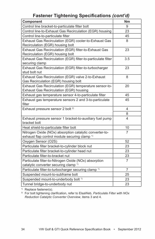
34 VW Golf & GTI Quick Reference Specification Book • September 2012
Component NmControl line bracket-to-particulate filter bolt 9Control line-to-Exhaust Gas Recirculation (EGR) housing 23Control line-to-particulate filter 45Exhaust Gas Recirculation (EGR) cooler-to-Exhaust Gas Recirculation (EGR) housing bolt
8
Exhaust Gas Recirculation (EGR) filter-to-Exhaust Gas Recirculation (EGR) housing bolt
23
Exhaust Gas Recirculation (EGR) filter-to-particulate filter securing clamp
3.5
Exhaust Gas Recirculation (EGR) filter-to-turbocharger stud bolt nut
23
Exhaust Gas Recirculation (EGR) valve 2-to-Exhaust Gas Recirculation (EGR) housing bolt
8
Exhaust Gas Recirculation (EGR) temperature sensor-to-Exhaust Gas Recirculation (EGR) housing
20
Exhaust gas temperature sensor 4-to-particulate filter 45Exhaust gas temperature sensors 2 and 3-to-particulate filter
45
Exhaust pressure sensor 2 bolt 2) 48
Exhaust pressure sensor 1 bracket-to-auxiliary fuel pump bracket bolt
4
Heat shield-to-particulate filter bolt 10Nitrogen Oxide (NOx) absorption catalytic converter-to-exhaust flap control module securing clamp 1)
7
Oxygen Sensor (O2S) 52Particulate filter bracket-to-cylinder block nut 23Particulate filter bracket-to-cylinder head nut 23Particulate filter-to-bracket nut 23Particulate filter-to-Nitrogen Oxide (NOx) absorption catalytic converter securing clamp 1)
7
Particulate filter-to-turbocharger securing clamp 1) 7Suspended mount-to-subframe bolt 25Suspended mount-to-underbody bolt 1) 23Tunnel bridge-to-underbody nut 23
1) Replace fastener(s).2) For bolt tightening clarification, refer to ElsaWeb, Particulate Filter with NOx
Reduction Catalytic Converter Overview, items 3 and 4.
Fastener Tightening Specifications (cont’d)
Engi
ne –
2.
0L C
JAA
(TD
I)
VW Golf & GTI Quick Reference Specification Book • September 2012 35
Ignition/Glow Plug System – 2.0L CJAA (TDI)
Fastener Tightening SpecificationsComponent NmFuel line bracket-to-intake manifold bolt 8Glow plug 12
Diesel Fuel Injection – 2.0L CJAA (TDI)Fastener Tightening Specifications
Component NmAir duct-to-lock carrier bolt 5Connecting pipe-to-Exhaust Gas Recirculation (EGR) vacuum regulator solenoid valve with Exhaust Gas Recirculation (EGR) potentiometer bolt
20
Exhaust Gas Recirculation (EGR) vacuum regulator solenoid valve with Exhaust Gas Recirculation (EGR) potentiometer-to-intake manifold bolt
10
Fuel line clamp bolt/nut 8Fuel pressure regulator valve-to-fuel rail 80Fuel pressure sensor-to-fuel rail 100Fuel rail-to-cylinder head cover bolt 22High pressure line clamp nut 8High pressure line-to-fuel injector fitting 28High pressure line-to-fuel rail fitting 28High pressure line-to-high pressure pump fitting 28High pressure pump-to-accessory bracket bolt 20- Tighten the long bolts an additional 180° plus an
additional (½ turn)
- Tighten the short bolts an additional 45° plus an additional (⅛ turn)
Intake manifold-to-cylinder head bolt 8Lower air filter housing-to-body bolt 8Mass Air Flow (MAF) sensor-to-upper air filter housing 3.5Oil dipstick guide tube-to-throttle valve control module bolt
10
Sealing cap-to-cylinder head cover bolt 5Tensioning plate-to-cylinder head cover nut 10Throttle valve control module-to-Exhaust Gas Recirculation (EGR) vacuum regulator solenoid valve with Exhaust Gas Recirculation (EGR) potentiometer bolt
10
Upper air filter housing-to-lower air filter housing bolt 5
36 VW Golf & GTI Quick Reference Specification Book • September 2012
ENGINE MECHANICAL – 2.0L CBFA, CCTA General, Technical Data
Engine Number Location
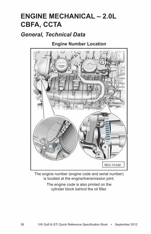
The engine number (engine code and serial number) is located at the engine/transmission joint.
The engine code is also printed on the cylinder block behind the oil filter.
Engi
ne –
2.
0L C
BFA
, CC
TA
VW Golf & GTI Quick Reference Specification Book • September 2012 37
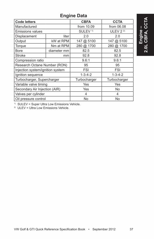
Engine DataCode letters CBFA CCTAManufactured from 10.09 from 06.08Emissions values SULEV 1) ULEV 2 2)
Displacement liter 2.0 2.0Output kW at RPM 147 @ 5100 147 @ 5100Torque Nm at RPM 280 @ 1700 280 @ 1700Bore diameter mm 82.5 82.5Stroke mm 92.8 92.8Compression ratio 9.6:1 9.6:1Research Octane Number (RON) 95 95Injection system/ignition system FSI FSIIgnition sequence 1-3-4-2 1-3-4-2Turbocharger, Supercharger Turbocharger TurbochargerVariable valve timing Yes YesSecondary Air Injection (AIR) Yes NoValves per cylinder 4 4Oil pressure control No No
1) SULEV = Super Ultra Low Emissions Vehicle.2) ULEV = Ultra Low Emissions Vehicle.
38 VW Golf & GTI Quick Reference Specification Book • September 2012
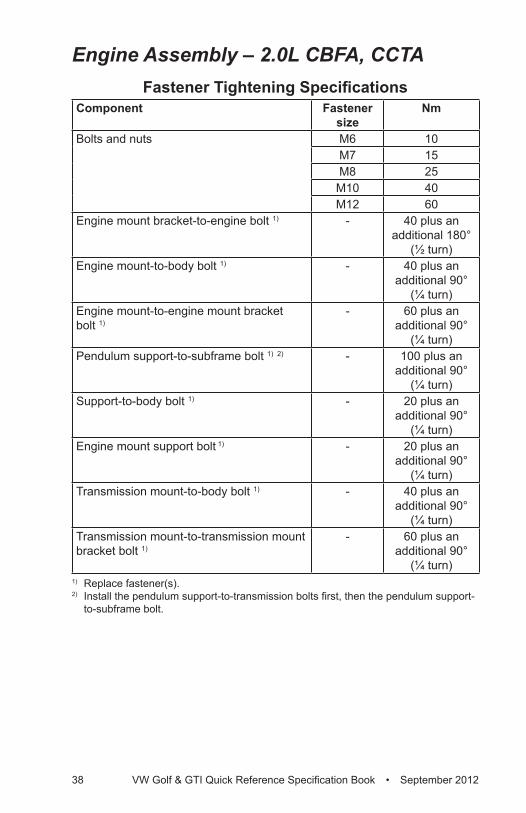
Engine Assembly – 2.0L CBFA, CCTAFastener Tightening Specifications
Component Fastener size
Nm
Bolts and nuts M6 10M7 15M8 25
M10 40M12 60
Engine mount bracket-to-engine bolt 1) - 40 plus an additional 180°
(½ turn)Engine mount-to-body bolt 1) - 40 plus an
additional 90° (¼ turn)
Engine mount-to-engine mount bracket bolt 1)
- 60 plus an additional 90°
(¼ turn)Pendulum support-to-subframe bolt 1) 2) - 100 plus an
additional 90° (¼ turn)
Support-to-body bolt 1) - 20 plus an additional 90°
(¼ turn)Engine mount support bolt 1) - 20 plus an
additional 90° (¼ turn)
Transmission mount-to-body bolt 1) - 40 plus an additional 90°
(¼ turn)Transmission mount-to-transmission mount bracket bolt 1)
- 60 plus an additional 90°
(¼ turn)1) Replace fastener(s).2) Install the pendulum support-to-transmission bolts first, then the pendulum support-
to-subframe bolt.
Engi
ne –
2.
0L C
BFA
, CC
TA
VW Golf & GTI Quick Reference Specification Book • September 2012 39
Crankshaft, Cylinder Block – 2.0L CBFA, CCTA
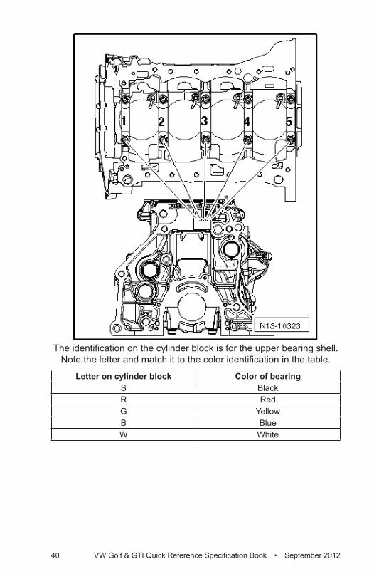
Cylinder Block Bearing Shell Identification
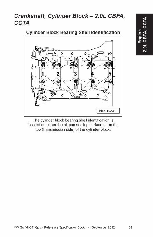
The cylinder block bearing shell identification is located on either the oil pan sealing surface or on the
top (transmission side) of the cylinder block.
40 VW Golf & GTI Quick Reference Specification Book • September 2012
The identification on the cylinder block is for the upper bearing shell. Note the letter and match it to the color identification in the table.
Letter on cylinder block Color of bearingS BlackR RedG YellowB BlueW White
Engi
ne –
2.
0L C
BFA
, CC
TA
VW Golf & GTI Quick Reference Specification Book • September 2012 41
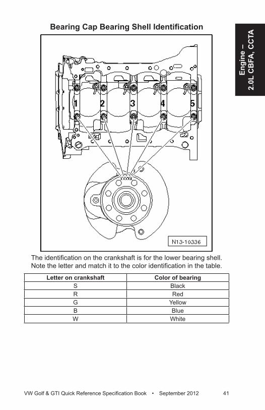
Bearing Cap Bearing Shell Identification
The identification on the crankshaft is for the lower bearing shell. Note the letter and match it to the color identification in the table.
Letter on crankshaft Color of bearingS BlackR RedG YellowB BlueW White
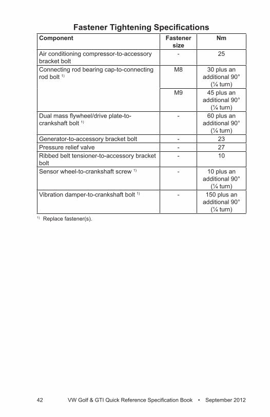
42 VW Golf & GTI Quick Reference Specification Book • September 2012
Fastener Tightening SpecificationsComponent Fastener
sizeNm
Air conditioning compressor-to-accessory bracket bolt
- 25
Connecting rod bearing cap-to-connecting rod bolt 1)
M8 30 plus an additional 90°
(¼ turn)M9 45 plus an
additional 90° (¼ turn)
Dual mass flywheel/drive plate-to-crankshaft bolt 1)
- 60 plus an additional 90°
(¼ turn)Generator-to-accessory bracket bolt - 23Pressure relief valve - 27Ribbed belt tensioner-to-accessory bracket bolt
- 10
Sensor wheel-to-crankshaft screw 1) - 10 plus an additional 90°
(¼ turn)Vibration damper-to-crankshaft bolt 1) - 150 plus an
additional 90° (¼ turn)
1) Replace fastener(s).
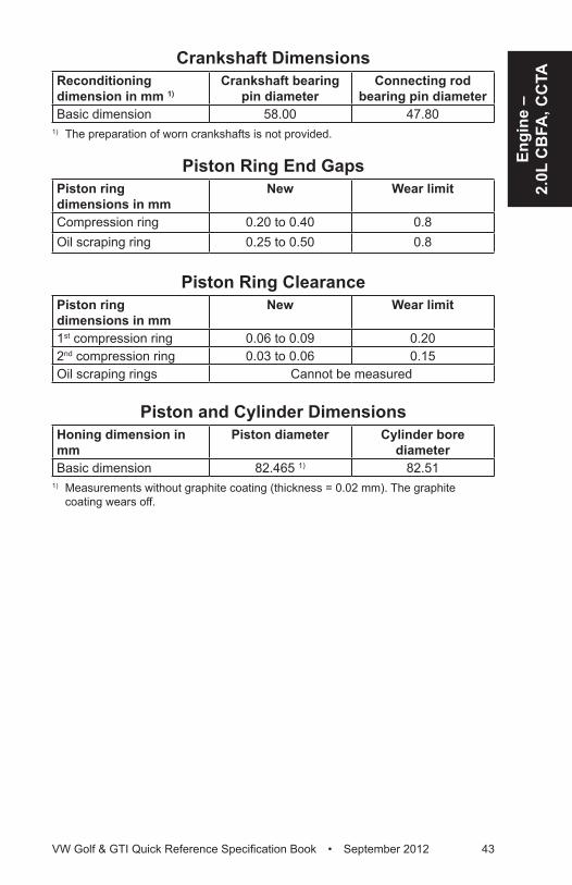
Engi
ne –
2.
0L C
BFA
, CC
TA
VW Golf & GTI Quick Reference Specification Book • September 2012 43
Crankshaft DimensionsReconditioning dimension in mm 1)
Crankshaft bearing pin diameter
Connecting rod bearing pin diameter
Basic dimension 58.00 47.801) The preparation of worn crankshafts is not provided.
Piston Ring End GapsPiston ring dimensions in mm
New Wear limit
Compression ring 0.20 to 0.40 0.8Oil scraping ring 0.25 to 0.50 0.8
Piston Ring ClearancePiston ring dimensions in mm
New Wear limit
1st compression ring 0.06 to 0.09 0.202nd compression ring 0.03 to 0.06 0.15Oil scraping rings Cannot be measured
Piston and Cylinder DimensionsHoning dimension in mm
Piston diameter Cylinder bore diameter
Basic dimension 82.465 1) 82.511) Measurements without graphite coating (thickness = 0.02 mm). The graphite
coating wears off.
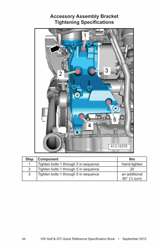
44 VW Golf & GTI Quick Reference Specification Book • September 2012
Accessory Assembly Bracket Tightening Specifications
Step Component Nm1 Tighten bolts 1 through 5 in sequence Hand-tighten2 Tighten bolts 1 through 5 in sequence 203 Tighten bolts 1 through 5 in sequence an additional
90° (¼ turn)
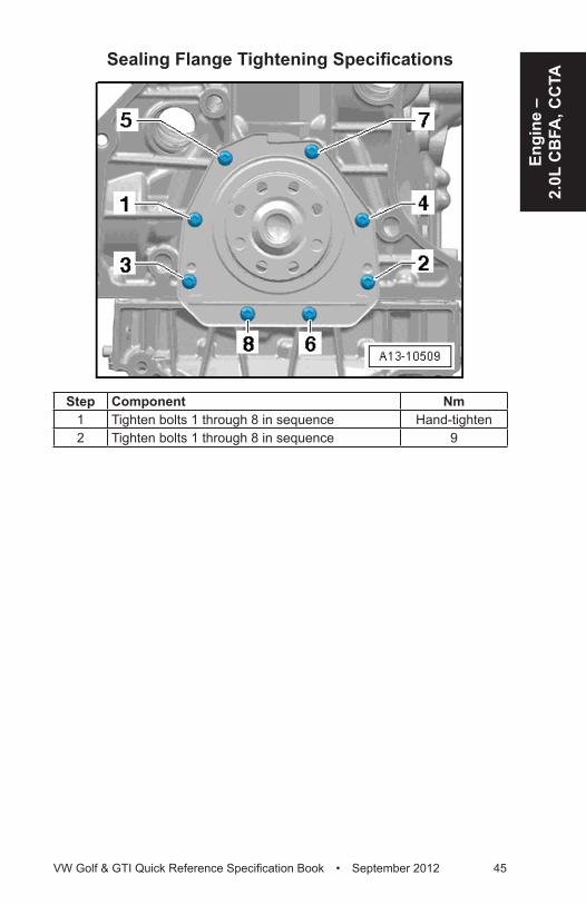
Engi
ne –
2.
0L C
BFA
, CC
TA
VW Golf & GTI Quick Reference Specification Book • September 2012 45
Sealing Flange Tightening Specifications
Step Component Nm1 Tighten bolts 1 through 8 in sequence Hand-tighten2 Tighten bolts 1 through 8 in sequence 9
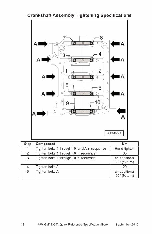
46 VW Golf & GTI Quick Reference Specification Book • September 2012
Crankshaft Assembly Tightening Specifications
Step Component Nm1 Tighten bolts 1 through 10 and A in sequence Hand-tighten2 Tighten bolts 1 through 10 in sequence 653 Tighten bolts 1 through 10 in sequence an additional
90° (¼ turn)4 Tighten bolts A 205 Tighten bolts A an additional
90° (¼ turn)
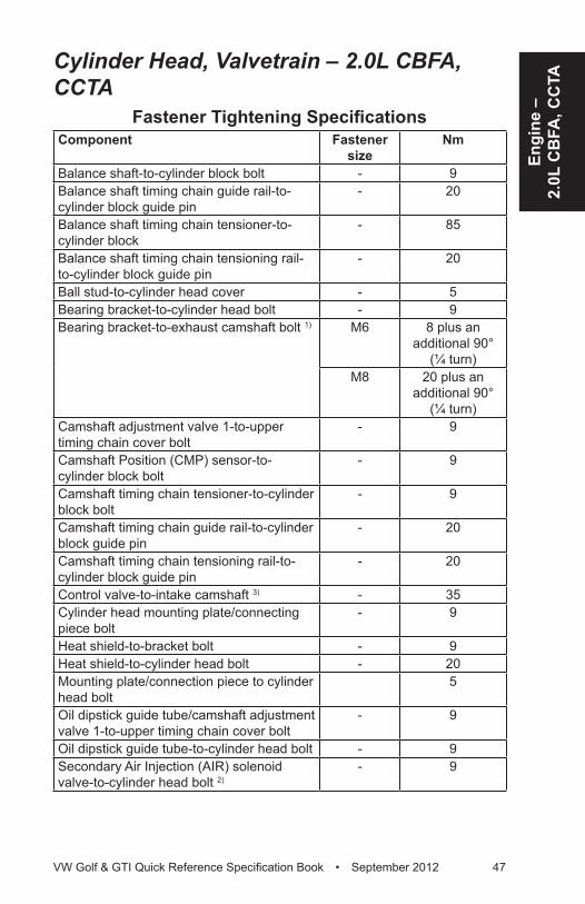
Engi
ne –
2.
0L C
BFA
, CC
TA
VW Golf & GTI Quick Reference Specification Book • September 2012 47
Cylinder Head, Valvetrain – 2.0L CBFA, CCTA
Fastener Tightening SpecificationsComponent Fastener
sizeNm
Balance shaft-to-cylinder block bolt - 9Balance shaft timing chain guide rail-to-cylinder block guide pin
- 20
Balance shaft timing chain tensioner-to-cylinder block
- 85
Balance shaft timing chain tensioning rail-to-cylinder block guide pin
- 20
Ball stud-to-cylinder head cover - 5Bearing bracket-to-cylinder head bolt - 9Bearing bracket-to-exhaust camshaft bolt 1) M6 8 plus an
additional 90° (¼ turn)
M8 20 plus an additional 90°
(¼ turn)Camshaft adjustment valve 1-to-upper timing chain cover bolt
- 9
Camshaft Position (CMP) sensor-to-cylinder block bolt
- 9
Camshaft timing chain tensioner-to-cylinder block bolt
- 9
Camshaft timing chain guide rail-to-cylinder block guide pin
- 20
Camshaft timing chain tensioning rail-to-cylinder block guide pin
- 20
Control valve-to-intake camshaft 3) - 35Cylinder head mounting plate/connecting piece bolt
- 9
Heat shield-to-bracket bolt - 9Heat shield-to-cylinder head bolt - 20Mounting plate/connection piece to cylinder head bolt
5
Oil dipstick guide tube/camshaft adjustment valve 1-to-upper timing chain cover bolt
- 9
Oil dipstick guide tube-to-cylinder head bolt - 9Secondary Air Injection (AIR) solenoid valve-to-cylinder head bolt 2)
- 9
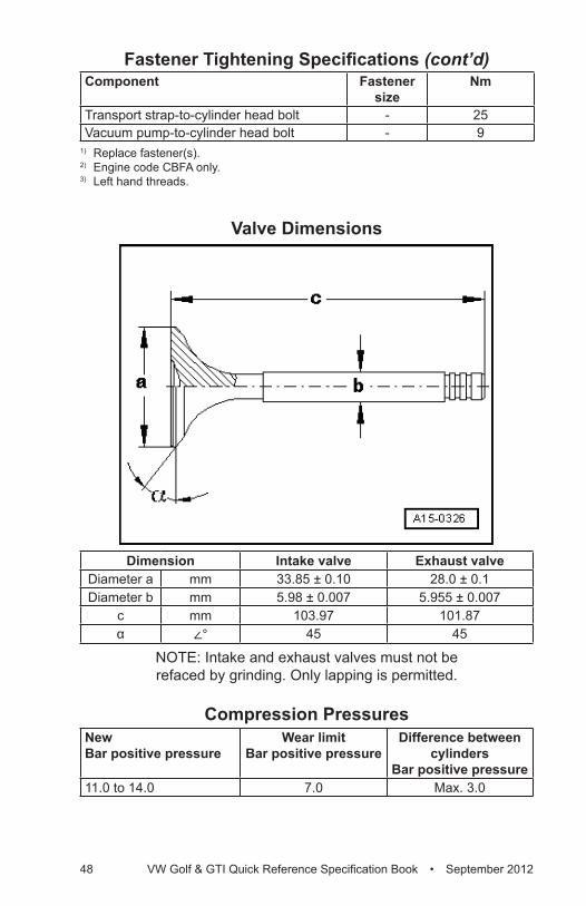
48 VW Golf & GTI Quick Reference Specification Book • September 2012
Component Fastener size
Nm
Transport strap-to-cylinder head bolt - 25Vacuum pump-to-cylinder head bolt - 9
1) Replace fastener(s). 2) Engine code CBFA only.3) Left hand threads.
Valve Dimensions
Dimension Intake valve Exhaust valveDiameter a mm 33.85 ± 0.10 28.0 ± 0.1Diameter b mm 5.98 ± 0.007 5.955 ± 0.007
c mm 103.97 101.87α ∠° 45 45
NOTE: Intake and exhaust valves must not be refaced by grinding. Only lapping is permitted.
Compression PressuresNew Bar positive pressure
Wear limit Bar positive pressure
Difference between cylinders
Bar positive pressure11.0 to 14.0 7.0 Max. 3.0
Fastener Tightening Specifications (cont’d)
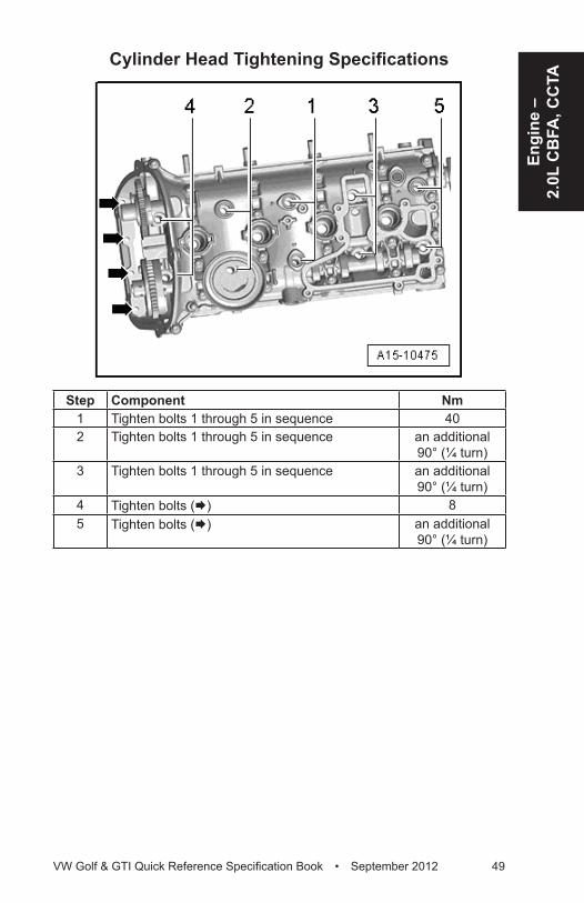
Engi
ne –
2.
0L C
BFA
, CC
TA
VW Golf & GTI Quick Reference Specification Book • September 2012 49
Cylinder Head Tightening Specifications
Step Component Nm1 Tighten bolts 1 through 5 in sequence 402 Tighten bolts 1 through 5 in sequence an additional
90° (¼ turn)3 Tighten bolts 1 through 5 in sequence an additional
90° (¼ turn)4 Tighten bolts (Æ) 85 Tighten bolts (Æ) an additional
90° (¼ turn)
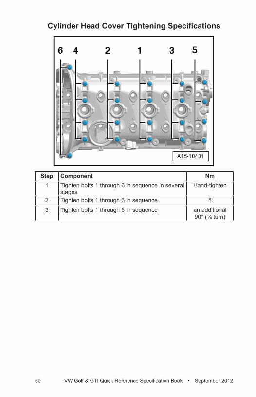
50 VW Golf & GTI Quick Reference Specification Book • September 2012
Cylinder Head Cover Tightening Specifications
Step Component Nm1 Tighten bolts 1 through 6 in sequence in several
stagesHand-tighten
2 Tighten bolts 1 through 6 in sequence 8
3 Tighten bolts 1 through 6 in sequence an additional 90° (¼ turn)
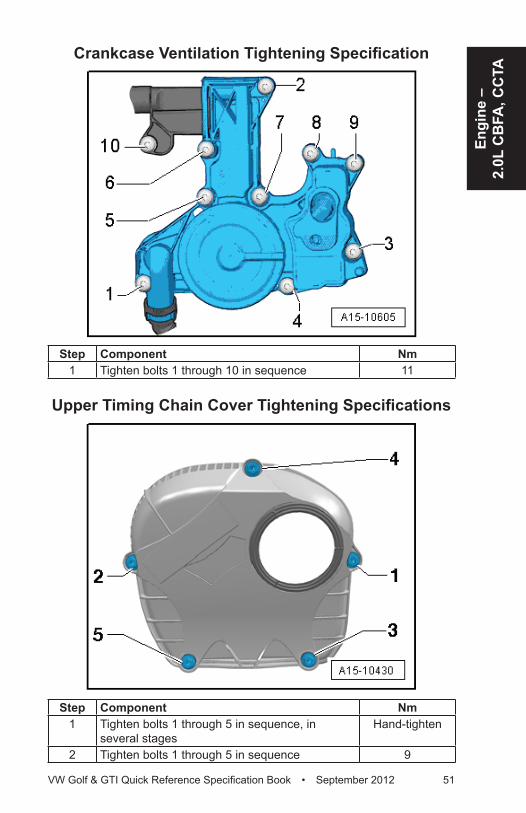
Engi
ne –
2.
0L C
BFA
, CC
TA
VW Golf & GTI Quick Reference Specification Book • September 2012 51
Crankcase Ventilation Tightening Specification
Step Component Nm1 Tighten bolts 1 through 10 in sequence 11
Upper Timing Chain Cover Tightening Specifications
Step Component Nm1 Tighten bolts 1 through 5 in sequence, in
several stagesHand-tighten
2 Tighten bolts 1 through 5 in sequence 9
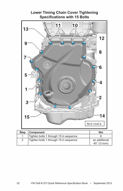
52 VW Golf & GTI Quick Reference Specification Book • September 2012
Lower Timing Chain Cover Tightening Specifications with 15 Bolts
Step Component Nm1 Tighten bolts 1 through 15 in sequence 82 Tighten bolts 1 through 15 in sequence an additional
45° (⅛ turn)
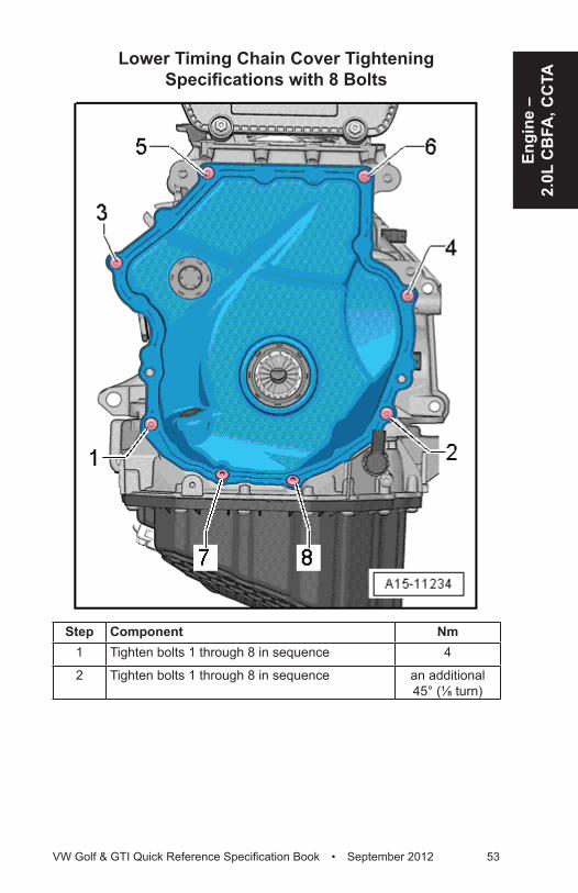
Engi
ne –
2.
0L C
BFA
, CC
TA
VW Golf & GTI Quick Reference Specification Book • September 2012 53
Lower Timing Chain Cover Tightening Specifications with 8 Bolts
Step Component Nm1 Tighten bolts 1 through 8 in sequence 4
2 Tighten bolts 1 through 8 in sequence an additional 45° (⅛ turn)
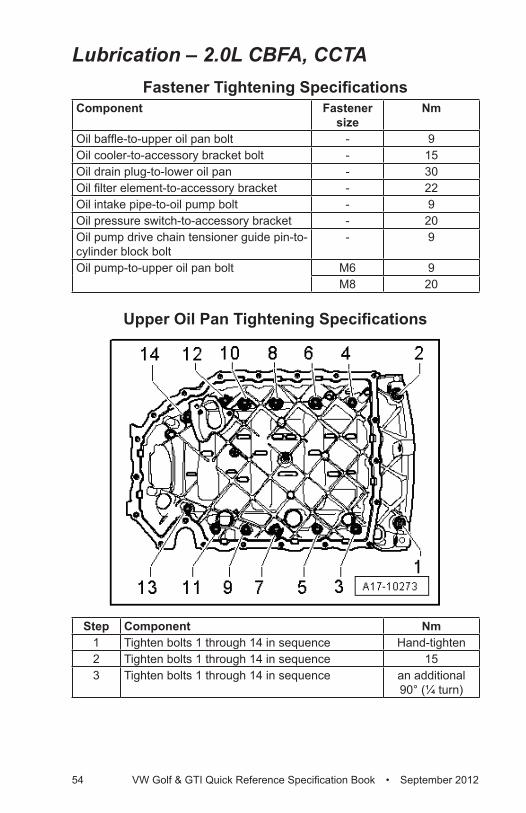
54 VW Golf & GTI Quick Reference Specification Book • September 2012
Lubrication – 2.0L CBFA, CCTAFastener Tightening Specifications
Component Fastener size
Nm
Oil baffle-to-upper oil pan bolt - 9Oil cooler-to-accessory bracket bolt - 15Oil drain plug-to-lower oil pan - 30Oil filter element-to-accessory bracket - 22Oil intake pipe-to-oil pump bolt - 9Oil pressure switch-to-accessory bracket - 20Oil pump drive chain tensioner guide pin-to-cylinder block bolt
- 9
Oil pump-to-upper oil pan bolt M6 9M8 20
Upper Oil Pan Tightening Specifications
Step Component Nm1 Tighten bolts 1 through 14 in sequence Hand-tighten2 Tighten bolts 1 through 14 in sequence 153 Tighten bolts 1 through 14 in sequence an additional
90° (¼ turn)
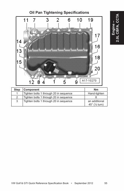
Engi
ne –
2.
0L C
BFA
, CC
TA
VW Golf & GTI Quick Reference Specification Book • September 2012 55
Oil Pan Tightening Specifications
Step Component Nm1 Tighten bolts 1 through 20 in sequence Hand-tighten2 Tighten bolts 1 through 20 in sequence 83 Tighten bolts 1 through 20 in sequence an additional
45° (⅛ turn)
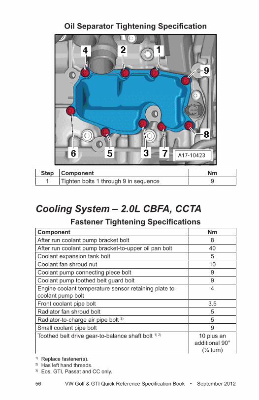
56 VW Golf & GTI Quick Reference Specification Book • September 2012
Oil Separator Tightening Specification
Step Component Nm1 Tighten bolts 1 through 9 in sequence 9
Cooling System – 2.0L CBFA, CCTAFastener Tightening Specifications
Component NmAfter run coolant pump bracket bolt 8After run coolant pump bracket-to-upper oil pan bolt 40Coolant expansion tank bolt 5Coolant fan shroud nut 10Coolant pump connecting piece bolt 9Coolant pump toothed belt guard bolt 9Engine coolant temperature sensor retaining plate to coolant pump bolt
4
Front coolant pipe bolt 3.5Radiator fan shroud bolt 5Radiator-to-charge air pipe bolt 3) 5Small coolant pipe bolt 9Toothed belt drive gear-to-balance shaft bolt 1) 2) 10 plus an
additional 90° (¼ turn)
1) Replace fastener(s). 2) Has left hand threads.3) Eos, GTI, Passat and CC only.
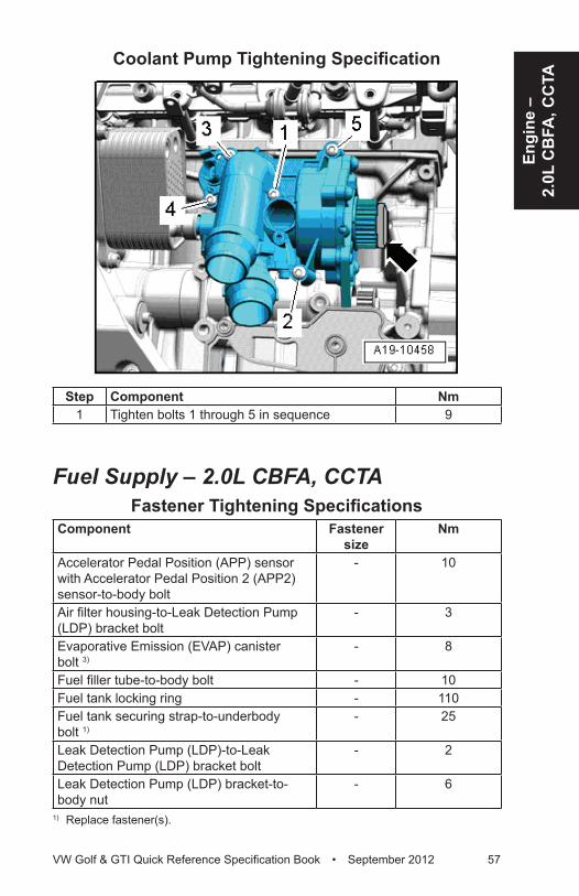
Engi
ne –
2.
0L C
BFA
, CC
TA
VW Golf & GTI Quick Reference Specification Book • September 2012 57
Coolant Pump Tightening Specification
Step Component Nm1 Tighten bolts 1 through 5 in sequence 9
Fuel Supply – 2.0L CBFA, CCTAFastener Tightening Specifications
Component Fastener size
Nm
Accelerator Pedal Position (APP) sensor with Accelerator Pedal Position 2 (APP2) sensor-to-body bolt
- 10
Air filter housing-to-Leak Detection Pump (LDP) bracket bolt
- 3
Evaporative Emission (EVAP) canister bolt 3)
- 8
Fuel filler tube-to-body bolt - 10Fuel tank locking ring - 110Fuel tank securing strap-to-underbody bolt 1)
- 25
Leak Detection Pump (LDP)-to-Leak Detection Pump (LDP) bracket bolt
- 2
Leak Detection Pump (LDP) bracket-to-body nut
- 6
1) Replace fastener(s).
58 VW Golf & GTI Quick Reference Specification Book • September 2012
Turbocharger, G-Charger – 2.0L CBFA, CCTA
Fastener Tightening SpecificationsComponent NmCharge Air Cooler (CAC) mounting bolt 5Charge air pipe bolt 8
Charge air pipe clamp 5.5Charge air pressure sensor-to-charge air pipe bolt 5Coolant return pipe-to-turbocharger banjo bolt 38Coolant return pipe-to-turbocharger bolt 9Coolant supply pipe-to-cylinder block banjo bolt 38Coolant supply pipe-to-cylinder block bolt 9Coolant supply pipe-to-turbocharger banjo bolt 38Cylinder block bracket bolt 2) 30Cylinder head fastening strip nut 1) 3) 30Cylinder head heat shield bolt 20Drive axle heat shield bolt 20Oil return pipe-to-cylinder block bolt 9Oil return pipe-to-turbocharger bolt 9Oil supply pipe-to-cylinder block bolt 9Oil supply pipe-to-turbocharger banjo bolt 33Oil supply pipe-to-turbocharger bolt 9Turbocharger bracket bolt 2) 30Turbocharger connection bolt 9Turbocharger recirculation valve-to-turbocharger bolt 7Vacuum diaphragm-to-turbocharger bolt 10Wastegate bypass regulator valve-to-turbocharger bolt 3
1) Replace fastener(s). 2) Lubricate the bolt with hot bolt paste. Refer to the Electronic Parts Catalog (ETKA).3) Lubricate the studs of the exhaust manifold with hot bolt paste. Refer to the
Electronic Parts Catalog (ETKA).
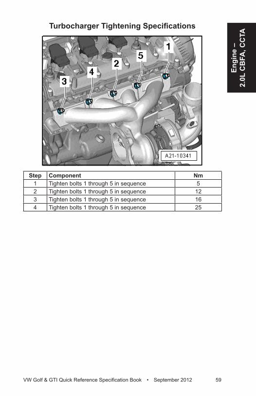
Engi
ne –
2.
0L C
BFA
, CC
TA
VW Golf & GTI Quick Reference Specification Book • September 2012 59
Turbocharger Tightening Specifications
Step Component Nm1 Tighten bolts 1 through 5 in sequence 52 Tighten bolts 1 through 5 in sequence 123 Tighten bolts 1 through 5 in sequence 164 Tighten bolts 1 through 5 in sequence 25
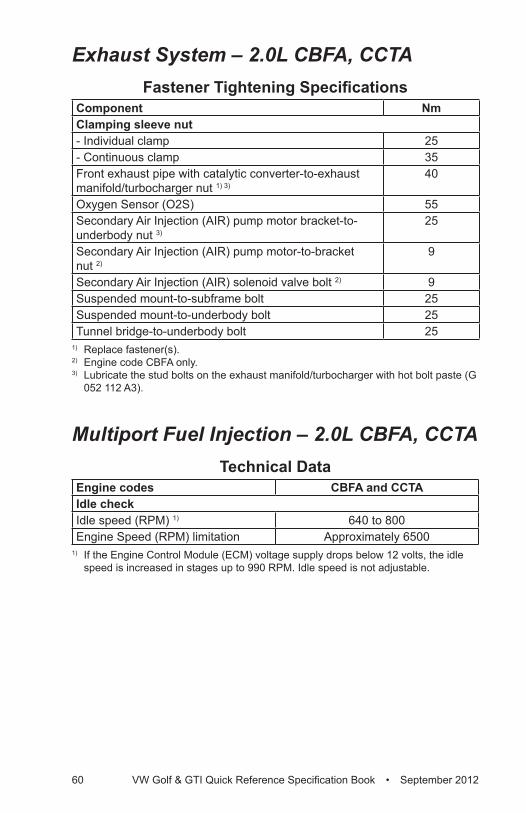
60 VW Golf & GTI Quick Reference Specification Book • September 2012
Exhaust System – 2.0L CBFA, CCTAFastener Tightening Specifications
Component NmClamping sleeve nut- Individual clamp 25- Continuous clamp 35Front exhaust pipe with catalytic converter-to-exhaust manifold/turbocharger nut 1) 3)
40
Oxygen Sensor (O2S) 55Secondary Air Injection (AIR) pump motor bracket-to-underbody nut 3)
25
Secondary Air Injection (AIR) pump motor-to-bracket nut 2)
9
Secondary Air Injection (AIR) solenoid valve bolt 2) 9Suspended mount-to-subframe bolt 25Suspended mount-to-underbody bolt 25Tunnel bridge-to-underbody bolt 25
1) Replace fastener(s). 2) Engine code CBFA only.3) Lubricate the stud bolts on the exhaust manifold/turbocharger with hot bolt paste (G
052 112 A3).
Multiport Fuel Injection – 2.0L CBFA, CCTATechnical Data
Engine codes CBFA and CCTAIdle checkIdle speed (RPM) 1) 640 to 800Engine Speed (RPM) limitation Approximately 6500
1) If the Engine Control Module (ECM) voltage supply drops below 12 volts, the idle speed is increased in stages up to 990 RPM. Idle speed is not adjustable.
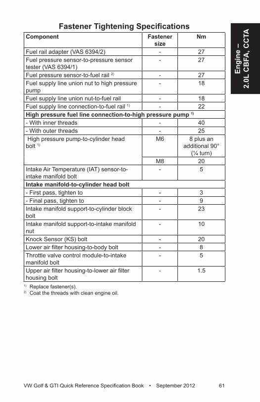
Engi
ne –
2.
0L C
BFA
, CC
TA
VW Golf & GTI Quick Reference Specification Book • September 2012 61
Fastener Tightening SpecificationsComponent Fastener
sizeNm
Fuel rail adapter (VAS 6394/2) - 27Fuel pressure sensor-to-pressure sensor tester (VAS 6394/1)
- 27
Fuel pressure sensor-to-fuel rail 2) - 27Fuel supply line union nut to high pressure pump
- 18
Fuel supply line union nut-to-fuel rail - 18Fuel supply line connection-to-fuel rail 1) - 22High pressure fuel line connection-to-high pressure pump 1)
- With inner threads - 40- With outer threads - 25 High pressure pump-to-cylinder head bolt 1)
M6 8 plus an additional 90°
(¼ turn)M8 20
Intake Air Temperature (IAT) sensor-to-intake manifold bolt
- 5
Intake manifold-to-cylinder head bolt- First pass, tighten to - 3- Final pass, tighten to - 9Intake manifold support-to-cylinder block bolt
- 23
Intake manifold support-to-intake manifold nut
- 10
Knock Sensor (KS) bolt - 20Lower air filter housing-to-body bolt - 8Throttle valve control module-to-intake manifold bolt
- 5
Upper air filter housing-to-lower air filter housing bolt
- 1.5
1) Replace fastener(s). 2) Coat the threads with clean engine oil.
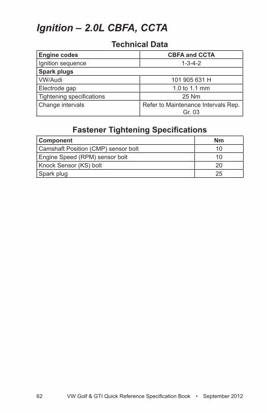
62 VW Golf & GTI Quick Reference Specification Book • September 2012
Ignition – 2.0L CBFA, CCTATechnical Data
Engine codes CBFA and CCTAIgnition sequence 1-3-4-2Spark plugsVW/Audi 101 905 631 HElectrode gap 1.0 to 1.1 mmTightening specifications 25 NmChange intervals Refer to Maintenance Intervals Rep.
Gr. 03
Fastener Tightening SpecificationsComponent NmCamshaft Position (CMP) sensor bolt 10Engine Speed (RPM) sensor bolt 10Knock Sensor (KS) bolt 20Spark plug 25
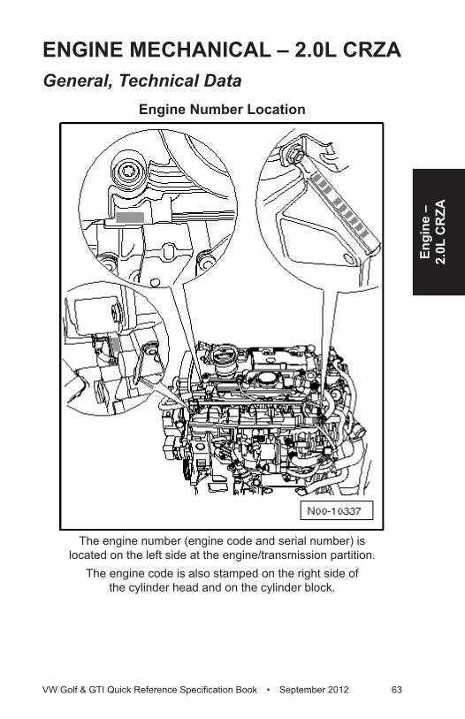
Engi
ne –
2.
0L C
RZA
VW Golf & GTI Quick Reference Specification Book • September 2012 63
ENGINE MECHANICAL – 2.0L CRZAGeneral, Technical Data
Engine Number Location
The engine number (engine code and serial number) is located on the left side at the engine/transmission partition.
The engine code is also stamped on the right side of the cylinder head and on the cylinder block.
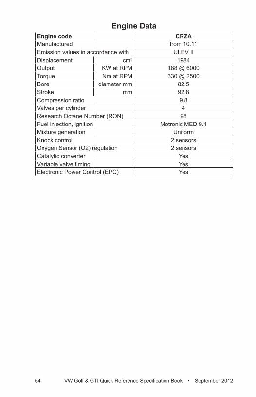
64 VW Golf & GTI Quick Reference Specification Book • September 2012
Engine DataEngine code CRZAManufactured from 10.11Emission values in accordance with ULEV IIDisplacement cm3 1984Output KW at RPM 188 @ 6000Torque Nm at RPM 330 @ 2500Bore diameter mm 82.5Stroke mm 92.8Compression ratio 9.8Valves per cylinder 4Research Octane Number (RON) 98Fuel injection, ignition Motronic MED 9.1Mixture generation UniformKnock control 2 sensorsOxygen Sensor (O2) regulation 2 sensorsCatalytic converter YesVariable valve timing YesElectronic Power Control (EPC) Yes

Engi
ne –
2.
0L C
RZA
VW Golf & GTI Quick Reference Specification Book • September 2012 65
Engine Assembly – 2.0L CRZAFastener Tightening Specifications
Component Fastener size
Nm
Bolts and nuts M6 10M7 15M8 25
M10 40M12 60
Engine Mount Tightening Specifications
Component NmBolts A 1) 20 plus an
additional 90° (¼ turn)
Bolts B 1) 40 plus an additional 90°
(¼ turn)Bolts C 1) 60 plus an
additional 90° (¼ turn)
1) Replace fastener(s).
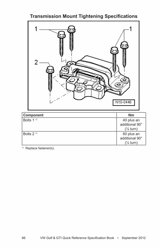
66 VW Golf & GTI Quick Reference Specification Book • September 2012
Transmission Mount Tightening Specifications
Component NmBolts 1 1) 40 plus an
additional 90° (¼ turn)
Bolts 2 1) 60 plus an additional 90°
(¼ turn)1) Replace fastener(s).
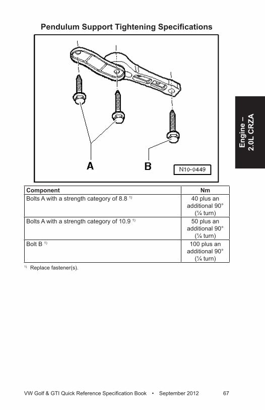
Engi
ne –
2.
0L C
RZA
VW Golf & GTI Quick Reference Specification Book • September 2012 67
Pendulum Support Tightening Specifications
Component NmBolts A with a strength category of 8.8 1) 40 plus an
additional 90° (¼ turn)
Bolts A with a strength category of 10.9 1) 50 plus an additional 90°
(¼ turn)Bolt B 1) 100 plus an
additional 90° (¼ turn)
1) Replace fastener(s).
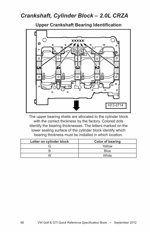
68 VW Golf & GTI Quick Reference Specification Book • September 2012
Crankshaft, Cylinder Block – 2.0L CRZAUpper Crankshaft Bearing Identification
The upper bearing shells are allocated to the cylinder block with the correct thickness by the factory. Colored dots
identify the bearing thicknesses. The letters marked on the lower sealing surface of the cylinder block identify which
bearing thickness must be installed in which location.
Letter on cylinder block Color of bearingG YellowB BlueW White
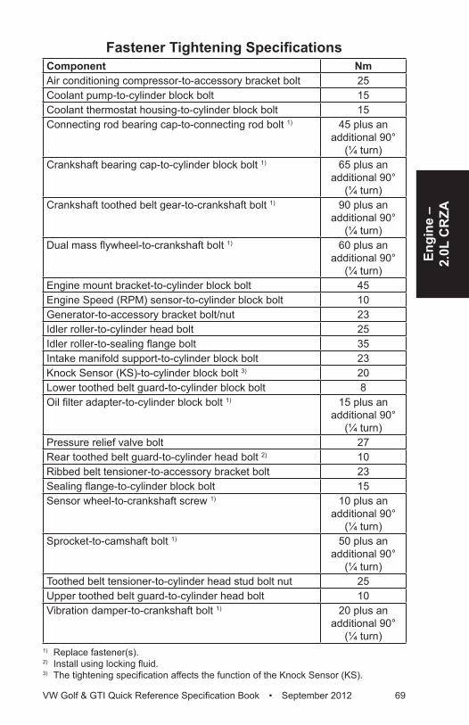
Engi
ne –
2.
0L C
RZA
VW Golf & GTI Quick Reference Specification Book • September 2012 69
Fastener Tightening SpecificationsComponent NmAir conditioning compressor-to-accessory bracket bolt 25Coolant pump-to-cylinder block bolt 15Coolant thermostat housing-to-cylinder block bolt 15Connecting rod bearing cap-to-connecting rod bolt 1) 45 plus an
additional 90° (¼ turn)
Crankshaft bearing cap-to-cylinder block bolt 1) 65 plus an additional 90°
(¼ turn)Crankshaft toothed belt gear-to-crankshaft bolt 1) 90 plus an
additional 90° (¼ turn)
Dual mass flywheel-to-crankshaft bolt 1) 60 plus an additional 90°
(¼ turn)Engine mount bracket-to-cylinder block bolt 45Engine Speed (RPM) sensor-to-cylinder block bolt 10Generator-to-accessory bracket bolt/nut 23Idler roller-to-cylinder head bolt 25Idler roller-to-sealing flange bolt 35Intake manifold support-to-cylinder block bolt 23Knock Sensor (KS)-to-cylinder block bolt 3) 20Lower toothed belt guard-to-cylinder block bolt 8Oil filter adapter-to-cylinder block bolt 1) 15 plus an
additional 90° (¼ turn)
Pressure relief valve bolt 27Rear toothed belt guard-to-cylinder head bolt 2) 10Ribbed belt tensioner-to-accessory bracket bolt 23Sealing flange-to-cylinder block bolt 15Sensor wheel-to-crankshaft screw 1) 10 plus an
additional 90° (¼ turn)
Sprocket-to-camshaft bolt 1) 50 plus an additional 90°
(¼ turn)Toothed belt tensioner-to-cylinder head stud bolt nut 25Upper toothed belt guard-to-cylinder head bolt 10Vibration damper-to-crankshaft bolt 1) 20 plus an
additional 90° (¼ turn)
1) Replace fastener(s).2) Install using locking fluid.3) The tightening specification affects the function of the Knock Sensor (KS).
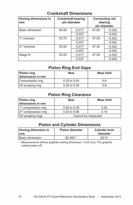
70 VW Golf & GTI Quick Reference Specification Book • September 2012
Crankshaft DimensionsHoning dimensions in mm
Crankshaft bearing pin diameter
Connecting rod bearing
pin diameterBasic dimension 54.00 -0.017 47.80 -0.022
-0.037 -0.0421st oversize 53.75 -0.017 47.55 -0.022
-0.037 -0.0422nd oversize 53.50 -0.017 47.30 -0.022
-0.037 -0.042Stage III 53.25 -0.017 47.05 -0.022
-0.037 -0.042
Piston Ring End GapsPiston ring dimensions in mm
New Wear limit
Compression ring 0.20 to 0.40 0.8Oil scraping ring 0.25 to 0.50 0.8
Piston Ring ClearancePiston ring dimensions in mm
New Wear limit
1st compression ring 0.06 to 0.09 0.202nd compression ring 0.03 to 0.06 0.15Oil scraping rings Cannot be measured
Piston and Cylinder DimensionsHoning dimension in mm
Piston diameter Cylinder bore diameter
Basic dimension 82.465 1) 82.511) Measurements without graphite coating (thickness = 0.02 mm). The graphite
coating wears off.
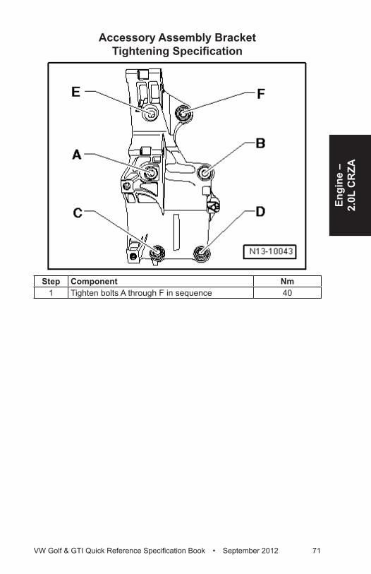
Engi
ne –
2.
0L C
RZA
VW Golf & GTI Quick Reference Specification Book • September 2012 71
Accessory Assembly Bracket Tightening Specification
Step Component Nm1 Tighten bolts A through F in sequence 40
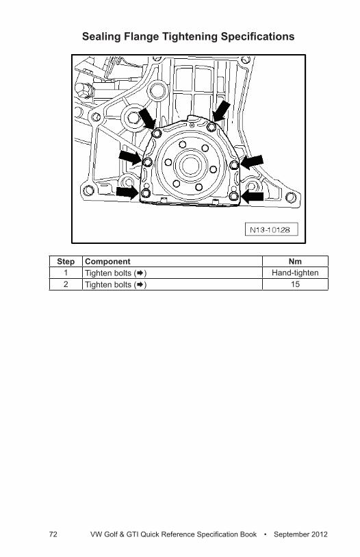
72 VW Golf & GTI Quick Reference Specification Book • September 2012
Sealing Flange Tightening Specifications
Step Component Nm1 Tighten bolts (Æ) Hand-tighten2 Tighten bolts (Æ) 15

Engi
ne –
2.
0L C
RZA
VW Golf & GTI Quick Reference Specification Book • September 2012 73
Cylinder Head, Valvetrain – 2.0L CRZAFastener Tightening Specifications
Component NmCamshaft adjuster-to-camshaft bolt 20 plus an
additional 45° (⅛ turn)
Camshaft adjustment valve 1-to-housing bolt 4Camshaft Position (CMP) sensor-to-cylinder head bolt 10Camshaft timing chain tensioner-to-cylinder block bolt 10Crankcase ventilation valve-to-cylinder head cover bolt 4Exhaust manifold stud bolt-to-cylinder head 20Guide frame-to-cylinder head bolt 1) 8 plus an
additional 90° (¼ turn)
Housing-to-cylinder head cover bolt 10Intake manifold stud bolt-to-cylinder head 10Sprocket-to-camshaft bolt 1) 50 plus an
additional 180° (½ turn)
Toothed belt tensioner stud bolt-to-cylinder head 10Transport strap-to-cylinder head bolt 25Wire bracket-to-housing bolt 10
1) Replace fastener(s).
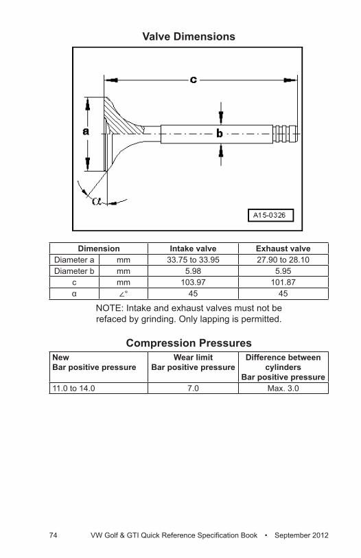
74 VW Golf & GTI Quick Reference Specification Book • September 2012
Valve Dimensions
Dimension Intake valve Exhaust valveDiameter a mm 33.75 to 33.95 27.90 to 28.10Diameter b mm 5.98 5.95
c mm 103.97 101.87α ∠° 45 45
NOTE: Intake and exhaust valves must not be refaced by grinding. Only lapping is permitted.
Compression PressuresNew Bar positive pressure
Wear limit Bar positive pressure
Difference between cylinders
Bar positive pressure11.0 to 14.0 7.0 Max. 3.0
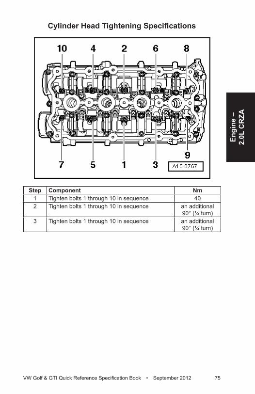
Engi
ne –
2.
0L C
RZA
VW Golf & GTI Quick Reference Specification Book • September 2012 75
Cylinder Head Tightening Specifications
Step Component Nm1 Tighten bolts 1 through 10 in sequence 402 Tighten bolts 1 through 10 in sequence an additional
90° (¼ turn)3 Tighten bolts 1 through 10 in sequence an additional
90° (¼ turn)
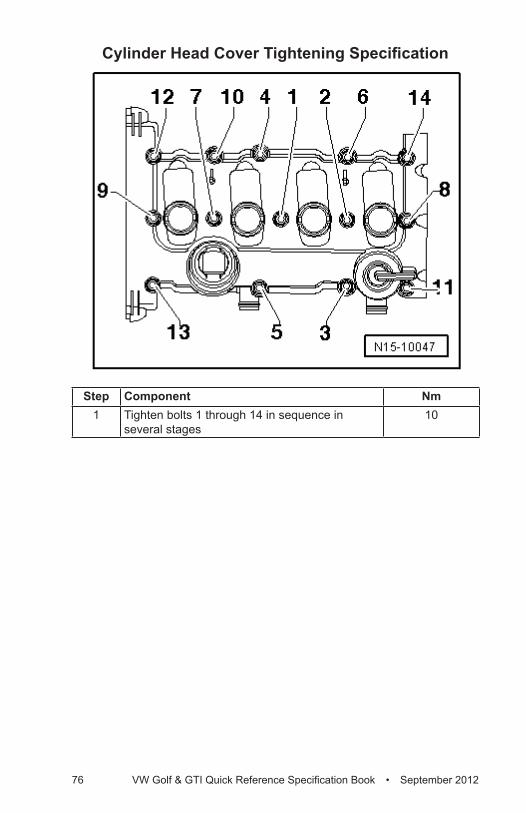
76 VW Golf & GTI Quick Reference Specification Book • September 2012
Cylinder Head Cover Tightening Specification
Step Component Nm1 Tighten bolts 1 through 14 in sequence in
several stages10
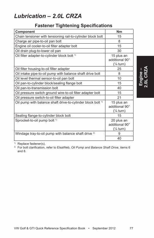
Engi
ne –
2.
0L C
RZA
VW Golf & GTI Quick Reference Specification Book • September 2012 77
Lubrication – 2.0L CRZAFastener Tightening Specifications
Component NmChain tensioner with tensioning rail-to-cylinder block bolt 15Charge air pipe-to-oil pan bolt 8Engine oil cooler-to-oil filter adapter bolt 15Oil drain plug-to-lower oil pan 30Oil filter adapter-to-cylinder block bolt 1) 15 plus an
additional 90° (¼ turn)
Oil filter housing-to-oil filter adapter 25Oil intake pipe-to-oil pump with balance shaft drive bolt 8Oil level thermal sensor-to-oil pan bolt 10Oil pan-to-cylinder block/sealing flange bolt 15Oil pan-to-transmission bolt 40Oil pressure switch ground wire-to-oil filter adapter bolt 15Oil pressure switch-to-oil filter adapter 21Oil pump with balance shaft drive-to-cylinder block bolt 1) 15 plus an
additional 90° (¼ turn)
Sealing flange-to-cylinder block bolt 15Sprocket-to-oil pump bolt 1) 20 plus an
additional 90° (¼ turn)
Windage tray-to-oil pump with balance shaft drive 2) 940
1) Replace fastener(s). 2) For bolt clarification, refer to ElsaWeb, Oil Pump and Balance Shaft Drive, items 6
and 8.
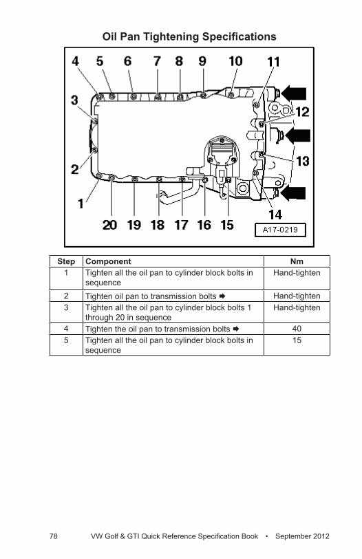
78 VW Golf & GTI Quick Reference Specification Book • September 2012
Oil Pan Tightening Specifications
Step Component Nm1 Tighten all the oil pan to cylinder block bolts in
sequenceHand-tighten
2 Tighten oil pan to transmission bolts Æ Hand-tighten3 Tighten all the oil pan to cylinder block bolts 1
through 20 in sequenceHand-tighten
4 Tighten the oil pan to transmission bolts Æ 405 Tighten all the oil pan to cylinder block bolts in
sequence15
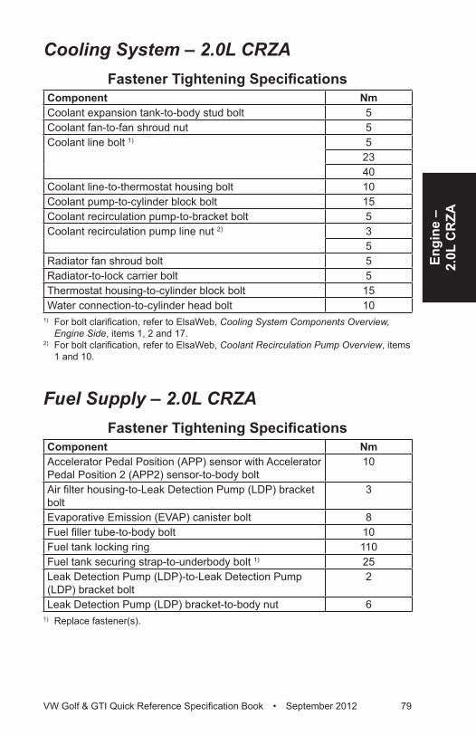
Engi
ne –
2.
0L C
RZA
VW Golf & GTI Quick Reference Specification Book • September 2012 79
Cooling System – 2.0L CRZAFastener Tightening Specifications
Component NmCoolant expansion tank-to-body stud bolt 5Coolant fan-to-fan shroud nut 5Coolant line bolt 1) 5
2340
Coolant line-to-thermostat housing bolt 10Coolant pump-to-cylinder block bolt 15Coolant recirculation pump-to-bracket bolt 5Coolant recirculation pump line nut 2) 3
5Radiator fan shroud bolt 5Radiator-to-lock carrier bolt 5Thermostat housing-to-cylinder block bolt 15Water connection-to-cylinder head bolt 10
1) For bolt clarification, refer to ElsaWeb, Cooling System Components Overview, Engine Side, items 1, 2 and 17.
2) For bolt clarification, refer to ElsaWeb, Coolant Recirculation Pump Overview, items 1 and 10.
Fuel Supply – 2.0L CRZAFastener Tightening Specifications
Component NmAccelerator Pedal Position (APP) sensor with Accelerator Pedal Position 2 (APP2) sensor-to-body bolt
10
Air filter housing-to-Leak Detection Pump (LDP) bracket bolt
3
Evaporative Emission (EVAP) canister bolt 8Fuel filler tube-to-body bolt 10Fuel tank locking ring 110Fuel tank securing strap-to-underbody bolt 1) 25Leak Detection Pump (LDP)-to-Leak Detection Pump (LDP) bracket bolt
2
Leak Detection Pump (LDP) bracket-to-body nut 61) Replace fastener(s).
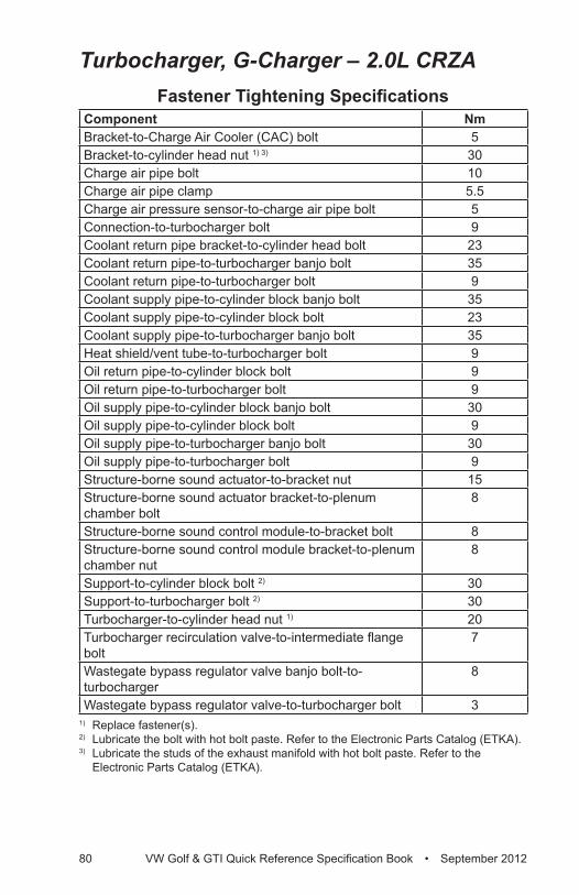
80 VW Golf & GTI Quick Reference Specification Book • September 2012
Turbocharger, G-Charger – 2.0L CRZAFastener Tightening Specifications
Component NmBracket-to-Charge Air Cooler (CAC) bolt 5Bracket-to-cylinder head nut 1) 3) 30Charge air pipe bolt 10Charge air pipe clamp 5.5Charge air pressure sensor-to-charge air pipe bolt 5Connection-to-turbocharger bolt 9Coolant return pipe bracket-to-cylinder head bolt 23Coolant return pipe-to-turbocharger banjo bolt 35Coolant return pipe-to-turbocharger bolt 9Coolant supply pipe-to-cylinder block banjo bolt 35Coolant supply pipe-to-cylinder block bolt 23Coolant supply pipe-to-turbocharger banjo bolt 35Heat shield/vent tube-to-turbocharger bolt 9Oil return pipe-to-cylinder block bolt 9Oil return pipe-to-turbocharger bolt 9Oil supply pipe-to-cylinder block banjo bolt 30Oil supply pipe-to-cylinder block bolt 9Oil supply pipe-to-turbocharger banjo bolt 30Oil supply pipe-to-turbocharger bolt 9Structure-borne sound actuator-to-bracket nut 15Structure-borne sound actuator bracket-to-plenum chamber bolt
8
Structure-borne sound control module-to-bracket bolt 8Structure-borne sound control module bracket-to-plenum chamber nut
8
Support-to-cylinder block bolt 2) 30Support-to-turbocharger bolt 2) 30Turbocharger-to-cylinder head nut 1) 20Turbocharger recirculation valve-to-intermediate flange bolt
7
Wastegate bypass regulator valve banjo bolt-to-turbocharger
8
Wastegate bypass regulator valve-to-turbocharger bolt 31) Replace fastener(s). 2) Lubricate the bolt with hot bolt paste. Refer to the Electronic Parts Catalog (ETKA).3) Lubricate the studs of the exhaust manifold with hot bolt paste. Refer to the
Electronic Parts Catalog (ETKA).
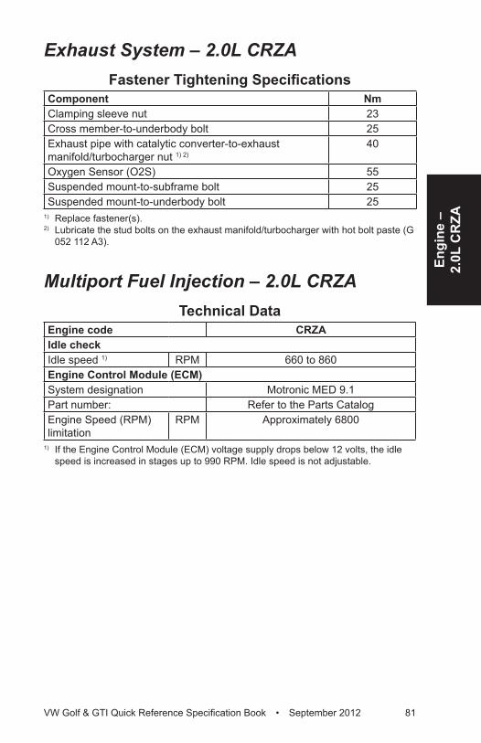
Engi
ne –
2.
0L C
RZA
VW Golf & GTI Quick Reference Specification Book • September 2012 81
Exhaust System – 2.0L CRZAFastener Tightening Specifications
Component NmClamping sleeve nut 23Cross member-to-underbody bolt 25Exhaust pipe with catalytic converter-to-exhaust manifold/turbocharger nut 1) 2)
40
Oxygen Sensor (O2S) 55Suspended mount-to-subframe bolt 25Suspended mount-to-underbody bolt 25
1) Replace fastener(s). 2) Lubricate the stud bolts on the exhaust manifold/turbocharger with hot bolt paste (G
052 112 A3).
Multiport Fuel Injection – 2.0L CRZATechnical Data
Engine code CRZAIdle checkIdle speed 1) RPM 660 to 860Engine Control Module (ECM) System designation Motronic MED 9.1Part number: Refer to the Parts CatalogEngine Speed (RPM) limitation
RPM Approximately 6800
1) If the Engine Control Module (ECM) voltage supply drops below 12 volts, the idle speed is increased in stages up to 990 RPM. Idle speed is not adjustable.
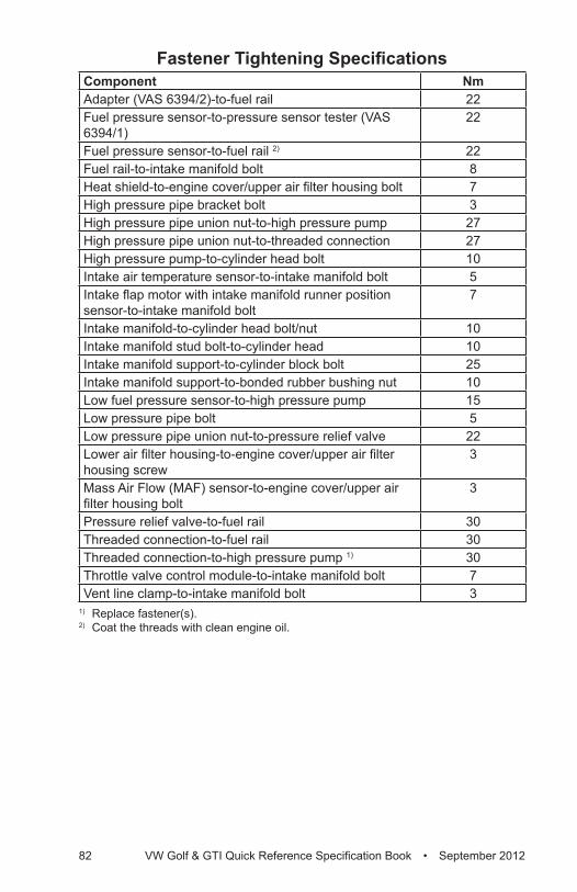
82 VW Golf & GTI Quick Reference Specification Book • September 2012
Fastener Tightening SpecificationsComponent NmAdapter (VAS 6394/2)-to-fuel rail 22Fuel pressure sensor-to-pressure sensor tester (VAS 6394/1)
22
Fuel pressure sensor-to-fuel rail 2) 22Fuel rail-to-intake manifold bolt 8Heat shield-to-engine cover/upper air filter housing bolt 7High pressure pipe bracket bolt 3High pressure pipe union nut-to-high pressure pump 27High pressure pipe union nut-to-threaded connection 27High pressure pump-to-cylinder head bolt 10Intake air temperature sensor-to-intake manifold bolt 5Intake flap motor with intake manifold runner position sensor-to-intake manifold bolt
7
Intake manifold-to-cylinder head bolt/nut 10Intake manifold stud bolt-to-cylinder head 10Intake manifold support-to-cylinder block bolt 25Intake manifold support-to-bonded rubber bushing nut 10Low fuel pressure sensor-to-high pressure pump 15Low pressure pipe bolt 5Low pressure pipe union nut-to-pressure relief valve 22Lower air filter housing-to-engine cover/upper air filter housing screw
3
Mass Air Flow (MAF) sensor-to-engine cover/upper air filter housing bolt
3
Pressure relief valve-to-fuel rail 30Threaded connection-to-fuel rail 30Threaded connection-to-high pressure pump 1) 30Throttle valve control module-to-intake manifold bolt 7Vent line clamp-to-intake manifold bolt 3
1) Replace fastener(s). 2) Coat the threads with clean engine oil.
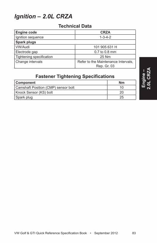
Engi
ne –
2.
0L C
RZA
VW Golf & GTI Quick Reference Specification Book • September 2012 83
Ignition – 2.0L CRZATechnical Data
Engine code CRZAIgnition sequence 1-3-4-2Spark plugsVW/Audi 101 905 631 HElectrode gap 0.7 to 0.8 mmTightening specification 25 NmChange intervals Refer to the Maintenance Intervals,
Rep. Gr. 03
Fastener Tightening SpecificationsComponent NmCamshaft Position (CMP) sensor bolt 10Knock Sensor (KS) bolt 20Spark plug 25
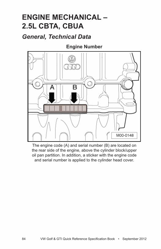
84 VW Golf & GTI Quick Reference Specification Book • September 2012
ENGINE MECHANICAL – 2.5L CBTA, CBUAGeneral, Technical Data
Engine Number
The engine code (A) and serial number (B) are located on the rear side of the engine, above the cylinder block/upper oil pan partition. In addition, a sticker with the engine code
and serial number is applied to the cylinder head cover.
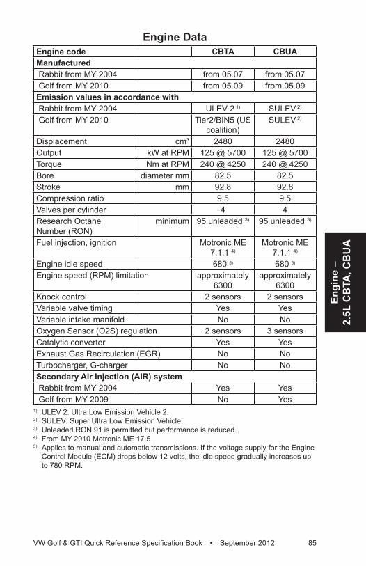
Engi
ne –
2.
5L C
BTA
, CB
UA
VW Golf & GTI Quick Reference Specification Book • September 2012 85
Engine DataEngine code CBTA CBUAManufactured Rabbit from MY 2004 from 05.07 from 05.07 Golf from MY 2010 from 05.09 from 05.09Emission values in accordance with Rabbit from MY 2004 ULEV 2 1) SULEV 2)
Golf from MY 2010 Tier2/BIN5 (US coalition)
SULEV 2)
Displacement cm³ 2480 2480Output kW at RPM 125 @ 5700 125 @ 5700Torque Nm at RPM 240 @ 4250 240 @ 4250Bore diameter mm 82.5 82.5Stroke mm 92.8 92.8Compression ratio 9.5 9.5Valves per cylinder 4 4Research Octane Number (RON)
minimum 95 unleaded 3) 95 unleaded 3)
Fuel injection, ignition Motronic ME 7.1.1 4)
Motronic ME 7.1.1 4)
Engine idle speed 680 5) 680 5)
Engine speed (RPM) limitation approximately 6300
approximately 6300
Knock control 2 sensors 2 sensorsVariable valve timing Yes YesVariable intake manifold No NoOxygen Sensor (O2S) regulation 2 sensors 3 sensorsCatalytic converter Yes YesExhaust Gas Recirculation (EGR) No NoTurbocharger, G-charger No NoSecondary Air Injection (AIR) system Rabbit from MY 2004 Yes Yes Golf from MY 2009 No Yes
1) ULEV 2: Ultra Low Emission Vehicle 2.2) SULEV: Super Ultra Low Emission Vehicle.3) Unleaded RON 91 is permitted but performance is reduced.4) From MY 2010 Motronic ME 17.55) Applies to manual and automatic transmissions. If the voltage supply for the Engine
Control Module (ECM) drops below 12 volts, the idle speed gradually increases up to 780 RPM.
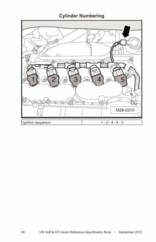
86 VW Golf & GTI Quick Reference Specification Book • September 2012
Cylinder Numbering
Ignition sequence 1 - 2 - 4 - 5 - 3
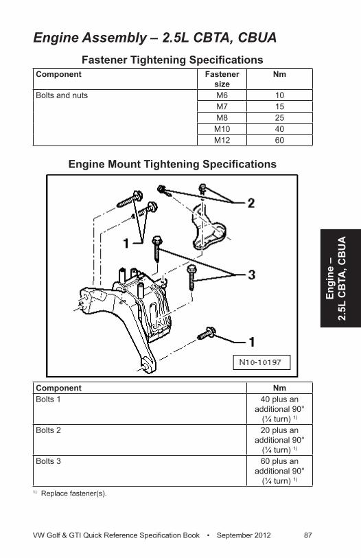
Engi
ne –
2.
5L C
BTA
, CB
UA
VW Golf & GTI Quick Reference Specification Book • September 2012 87
Engine Assembly – 2.5L CBTA, CBUAFastener Tightening Specifications
Component Fastener size
Nm
Bolts and nuts M6 10M7 15M8 25
M10 40M12 60
Engine Mount Tightening Specifications
Component NmBolts 1 40 plus an
additional 90° (¼ turn) 1)
Bolts 2 20 plus an additional 90°
(¼ turn) 1)
Bolts 3 60 plus an additional 90°
(¼ turn) 1)
1) Replace fastener(s).
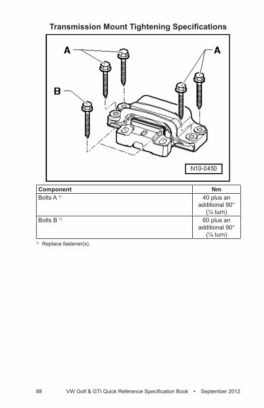
88 VW Golf & GTI Quick Reference Specification Book • September 2012
Transmission Mount Tightening Specifications
Component NmBolts A 1) 40 plus an
additional 90° (¼ turn)
Bolts B 1) 60 plus an additional 90°
(¼ turn) 1) Replace fastener(s).
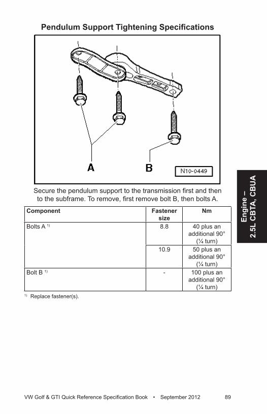
Engi
ne –
2.
5L C
BTA
, CB
UA
VW Golf & GTI Quick Reference Specification Book • September 2012 89
Pendulum Support Tightening Specifications
Secure the pendulum support to the transmission first and then to the subframe. To remove, first remove bolt B, then bolts A.
Component Fastener size
Nm
Bolts A 1) 8.8 40 plus an additional 90°
(¼ turn)10.9 50 plus an
additional 90° (¼ turn)
Bolt B 1) - 100 plus an additional 90°
(¼ turn)1) Replace fastener(s).
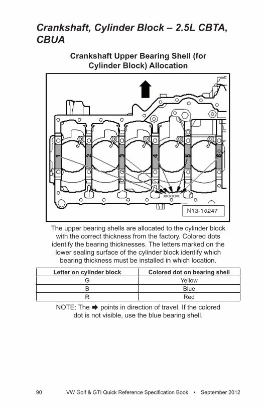
90 VW Golf & GTI Quick Reference Specification Book • September 2012
Crankshaft, Cylinder Block – 2.5L CBTA, CBUA
Crankshaft Upper Bearing Shell (for Cylinder Block) Allocation
The upper bearing shells are allocated to the cylinder block with the correct thickness from the factory. Colored dots
identify the bearing thicknesses. The letters marked on the lower sealing surface of the cylinder block identify which
bearing thickness must be installed in which location.
Letter on cylinder block Colored dot on bearing shellG YellowB BlueR Red
NOTE: The Æ points in direction of travel. If the colored dot is not visible, use the blue bearing shell.
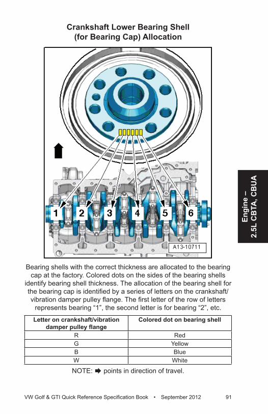
Engi
ne –
2.
5L C
BTA
, CB
UA
VW Golf & GTI Quick Reference Specification Book • September 2012 91
Crankshaft Lower Bearing Shell (for Bearing Cap) Allocation
Bearing shells with the correct thickness are allocated to the bearing cap at the factory. Colored dots on the sides of the bearing shells
identify bearing shell thickness. The allocation of the bearing shell for the bearing cap is identified by a series of letters on the crankshaft/vibration damper pulley flange. The first letter of the row of letters
represents bearing “1”, the second letter is for bearing “2”, etc.
Letter on crankshaft/vibration damper pulley flange
Colored dot on bearing shell
R RedG YellowB BlueW White
NOTE: Æ points in direction of travel.
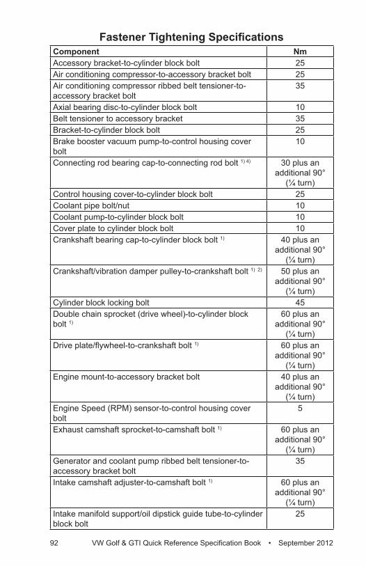
92 VW Golf & GTI Quick Reference Specification Book • September 2012
Fastener Tightening SpecificationsComponent NmAccessory bracket-to-cylinder block bolt 25Air conditioning compressor-to-accessory bracket bolt 25Air conditioning compressor ribbed belt tensioner-to-accessory bracket bolt
35
Axial bearing disc-to-cylinder block bolt 10Belt tensioner to accessory bracket 35Bracket-to-cylinder block bolt 25Brake booster vacuum pump-to-control housing cover bolt
10
Connecting rod bearing cap-to-connecting rod bolt 1) 4) 30 plus an additional 90°
(¼ turn)Control housing cover-to-cylinder block bolt 25Coolant pipe bolt/nut 10Coolant pump-to-cylinder block bolt 10Cover plate to cylinder block bolt 10Crankshaft bearing cap-to-cylinder block bolt 1) 40 plus an
additional 90° (¼ turn)
Crankshaft/vibration damper pulley-to-crankshaft bolt 1) 2) 50 plus an additional 90°
(¼ turn)Cylinder block locking bolt 45Double chain sprocket (drive wheel)-to-cylinder block bolt 1)
60 plus an additional 90°
(¼ turn)Drive plate/flywheel-to-crankshaft bolt 1) 60 plus an
additional 90° (¼ turn)
Engine mount-to-accessory bracket bolt 40 plus an additional 90°
(¼ turn)Engine Speed (RPM) sensor-to-control housing cover bolt
5
Exhaust camshaft sprocket-to-camshaft bolt 1) 60 plus an additional 90°
(¼ turn)Generator and coolant pump ribbed belt tensioner-to-accessory bracket bolt
35
Intake camshaft adjuster-to-camshaft bolt 1) 60 plus an additional 90°
(¼ turn)Intake manifold support/oil dipstick guide tube-to-cylinder block bolt
25
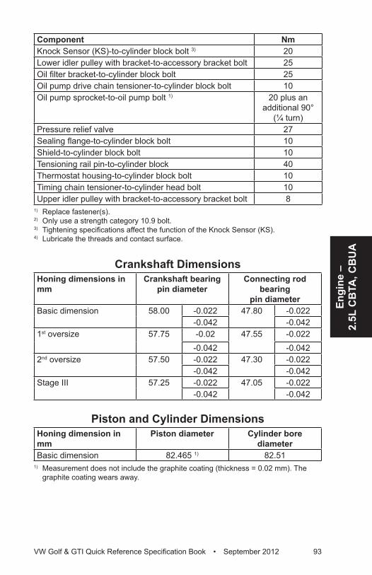
Engi
ne –
2.
5L C
BTA
, CB
UA
VW Golf & GTI Quick Reference Specification Book • September 2012 93
Component NmKnock Sensor (KS)-to-cylinder block bolt 3) 20Lower idler pulley with bracket-to-accessory bracket bolt 25Oil filter bracket-to-cylinder block bolt 25Oil pump drive chain tensioner-to-cylinder block bolt 10Oil pump sprocket-to-oil pump bolt 1) 20 plus an
additional 90° (¼ turn)
Pressure relief valve 27Sealing flange-to-cylinder block bolt 10Shield-to-cylinder block bolt 10Tensioning rail pin-to-cylinder block 40Thermostat housing-to-cylinder block bolt 10Timing chain tensioner-to-cylinder head bolt 10Upper idler pulley with bracket-to-accessory bracket bolt 8
1) Replace fastener(s).2) Only use a strength category 10.9 bolt.3) Tightening specifications affect the function of the Knock Sensor (KS).4) Lubricate the threads and contact surface.
Crankshaft DimensionsHoning dimensions in mm
Crankshaft bearing pin diameter
Connecting rod bearing
pin diameterBasic dimension 58.00 -0.022 47.80 -0.022
-0.042 -0.0421st oversize 57.75 -0.02 47.55 -0.022
-0.042 -0.0422nd oversize 57.50 -0.022 47.30 -0.022
-0.042 -0.042Stage III 57.25 -0.022 47.05 -0.022
-0.042 -0.042
Piston and Cylinder DimensionsHoning dimension in mm
Piston diameter Cylinder bore diameter
Basic dimension 82.465 1) 82.511) Measurement does not include the graphite coating (thickness = 0.02 mm). The
graphite coating wears away.
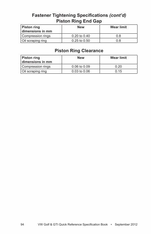
94 VW Golf & GTI Quick Reference Specification Book • September 2012
Piston Ring End GapPiston ringdimensions in mm
New Wear limit
Compression rings 0.20 to 0.40 0.8Oil scraping ring 0.25 to 0.50 0.8
Piston Ring ClearancePiston ringdimensions in mm
New Wear limit
Compression rings 0.06 to 0.09 0.20Oil scraping ring 0.03 to 0.06 0.15
Fastener Tightening Specifications (cont’d)
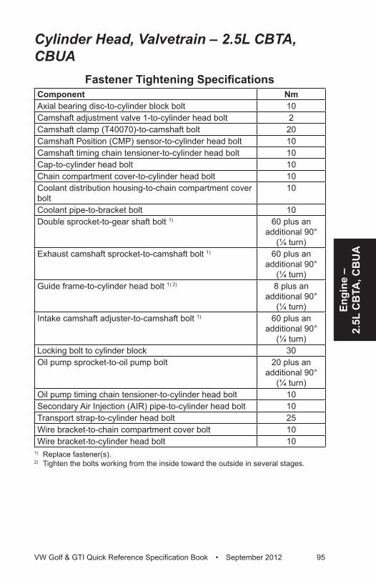
Engi
ne –
2.
5L C
BTA
, CB
UA
VW Golf & GTI Quick Reference Specification Book • September 2012 95
Cylinder Head, Valvetrain – 2.5L CBTA, CBUA
Fastener Tightening SpecificationsComponent NmAxial bearing disc-to-cylinder block bolt 10Camshaft adjustment valve 1-to-cylinder head bolt 2Camshaft clamp (T40070)-to-camshaft bolt 20Camshaft Position (CMP) sensor-to-cylinder head bolt 10Camshaft timing chain tensioner-to-cylinder head bolt 10Cap-to-cylinder head bolt 10Chain compartment cover-to-cylinder head bolt 10Coolant distribution housing-to-chain compartment cover bolt
10
Coolant pipe-to-bracket bolt 10Double sprocket-to-gear shaft bolt 1) 60 plus an
additional 90° (¼ turn)
Exhaust camshaft sprocket-to-camshaft bolt 1) 60 plus an additional 90°
(¼ turn)Guide frame-to-cylinder head bolt 1) 2) 8 plus an
additional 90° (¼ turn)
Intake camshaft adjuster-to-camshaft bolt 1) 60 plus an additional 90°
(¼ turn)Locking bolt to cylinder block 30Oil pump sprocket-to-oil pump bolt 20 plus an
additional 90° (¼ turn)
Oil pump timing chain tensioner-to-cylinder head bolt 10Secondary Air Injection (AIR) pipe-to-cylinder head bolt 10Transport strap-to-cylinder head bolt 25Wire bracket-to-chain compartment cover bolt 10Wire bracket-to-cylinder head bolt 10
1) Replace fastener(s).2) Tighten the bolts working from the inside toward the outside in several stages.
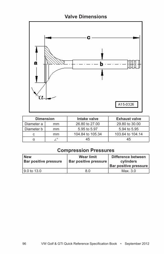
96 VW Golf & GTI Quick Reference Specification Book • September 2012
Valve Dimensions
Dimension Intake valve Exhaust valveDiameter a mm 26.80 to 27.00 29.80 to 30.00Diameter b mm 5.95 to 5.97 5.94 to 5.95
c mm 104.84 to 105.34 103.64 to 104.14α ∠° 45 45
Compression PressuresNew Bar positive pressure
Wear limit Bar positive pressure
Difference between cylinders
Bar positive pressure9.0 to 13.0 8.0 Max. 3.0
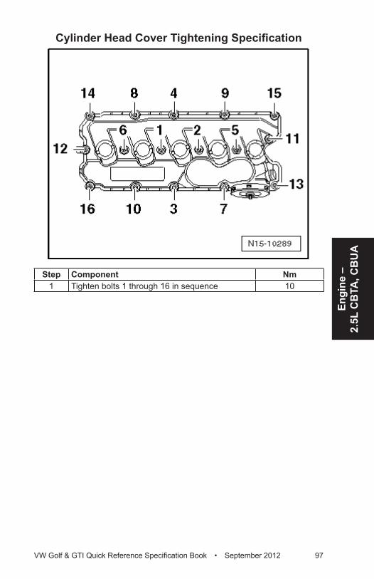
Engi
ne –
2.
5L C
BTA
, CB
UA
VW Golf & GTI Quick Reference Specification Book • September 2012 97
Cylinder Head Cover Tightening Specification
Step Component Nm1 Tighten bolts 1 through 16 in sequence 10
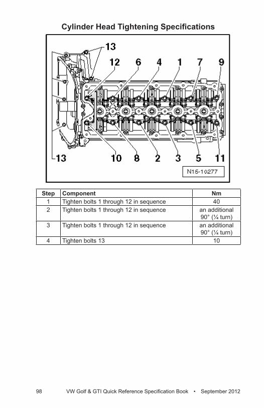
98 VW Golf & GTI Quick Reference Specification Book • September 2012
Cylinder Head Tightening Specifications
Step Component Nm1 Tighten bolts 1 through 12 in sequence 402 Tighten bolts 1 through 12 in sequence an additional
90° (¼ turn)3 Tighten bolts 1 through 12 in sequence an additional
90° (¼ turn)4 Tighten bolts 13 10
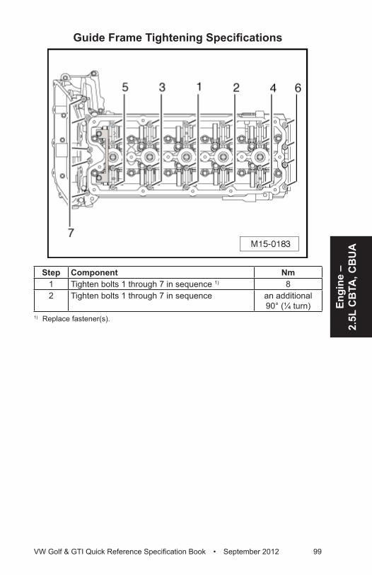
Engi
ne –
2.
5L C
BTA
, CB
UA
VW Golf & GTI Quick Reference Specification Book • September 2012 99
Guide Frame Tightening Specifications
Step Component Nm1 Tighten bolts 1 through 7 in sequence 1) 82 Tighten bolts 1 through 7 in sequence an additional
90° (¼ turn)1) Replace fastener(s).
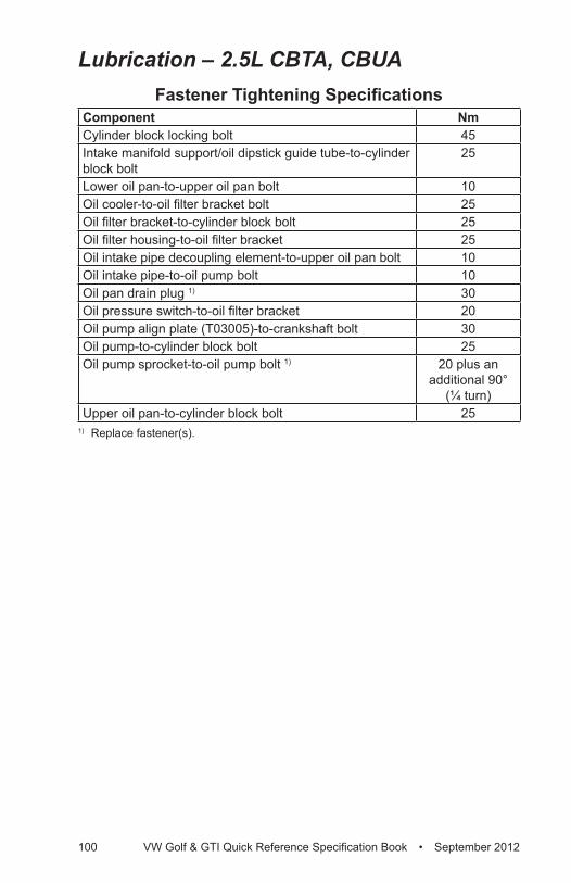
100 VW Golf & GTI Quick Reference Specification Book • September 2012
Lubrication – 2.5L CBTA, CBUAFastener Tightening Specifications
Component NmCylinder block locking bolt 45Intake manifold support/oil dipstick guide tube-to-cylinder block bolt
25
Lower oil pan-to-upper oil pan bolt 10Oil cooler-to-oil filter bracket bolt 25Oil filter bracket-to-cylinder block bolt 25Oil filter housing-to-oil filter bracket 25Oil intake pipe decoupling element-to-upper oil pan bolt 10Oil intake pipe-to-oil pump bolt 10Oil pan drain plug 1) 30Oil pressure switch-to-oil filter bracket 20Oil pump align plate (T03005)-to-crankshaft bolt 30Oil pump-to-cylinder block bolt 25Oil pump sprocket-to-oil pump bolt 1) 20 plus an
additional 90° (¼ turn)
Upper oil pan-to-cylinder block bolt 251) Replace fastener(s).
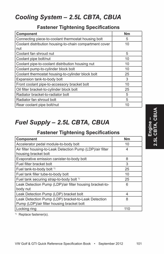
Engi
ne –
2.
5L C
BTA
, CB
UA
VW Golf & GTI Quick Reference Specification Book • September 2012 101
Cooling System – 2.5L CBTA, CBUAFastener Tightening Specifications
Component NmConnecting piece-to-coolant thermostat housing bolt 5Coolant distribution housing-to-chain compartment cover nut
10
Coolant fan shroud nut 5Coolant pipe bolt/nut 10Coolant pipe-to-coolant distribution housing nut 10Coolant pump-to-cylinder block bolt 10Coolant thermostat housing-to-cylinder block bolt 25Expansion tank-to-body bolt 3Front coolant pipe-to-accessory bracket bolt 10Oil filter bracket-to-cylinder block bolt 25Radiator bracket-to-radiator bolt 5Radiator fan shroud bolt 5Rear coolant pipe bolt/nut 10
Fuel Supply – 2.5L CBTA, CBUAFastener Tightening Specifications
Component NmAccelerator pedal module-to-body bolt 10Air filter housing-to-Leak Detection Pump (LDP)/air filter housing bracket bolt
4
Evaporative emission canister-to-body bolt 8Fuel filter bracket bolt 3Fuel tank-to-body bolt 1) 25Fuel tank filler tube-to-body bolt 10Fuel tank securing strap-to-body bolt 1) 25Leak Detection Pump (LDP)/air filter housing bracket-to-body nut
6
Leak Detection Pump (LDP) bracket bolt 4Leak Detection Pump (LDP) bracket-to-Leak Detection Pump (LDP)/air filter housing bracket bolt
8
Locking ring 1101) Replace fastener(s).
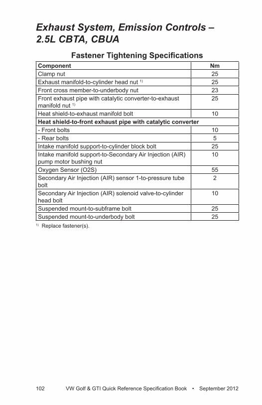
102 VW Golf & GTI Quick Reference Specification Book • September 2012
Exhaust System, Emission Controls – 2.5L CBTA, CBUA
Fastener Tightening SpecificationsComponent NmClamp nut 25Exhaust manifold-to-cylinder head nut 1) 25Front cross member-to-underbody nut 23Front exhaust pipe with catalytic converter-to-exhaust manifold nut 1)
25
Heat shield-to-exhaust manifold bolt 10Heat shield-to-front exhaust pipe with catalytic converter- Front bolts 10- Rear bolts 5Intake manifold support-to-cylinder block bolt 25Intake manifold support-to-Secondary Air Injection (AIR) pump motor bushing nut
10
Oxygen Sensor (O2S) 55Secondary Air Injection (AIR) sensor 1-to-pressure tube bolt
2
Secondary Air Injection (AIR) solenoid valve-to-cylinder head bolt
10
Suspended mount-to-subframe bolt 25Suspended mount-to-underbody bolt 25
1) Replace fastener(s).
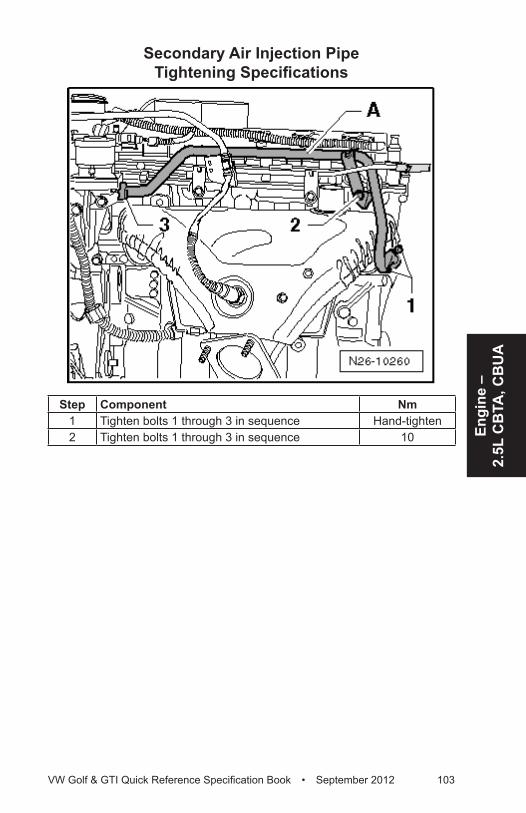
Engi
ne –
2.
5L C
BTA
, CB
UA
VW Golf & GTI Quick Reference Specification Book • September 2012 103
Secondary Air Injection Pipe Tightening Specifications
Step Component Nm1 Tighten bolts 1 through 3 in sequence Hand-tighten2 Tighten bolts 1 through 3 in sequence 10
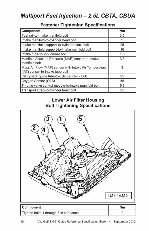
104 VW Golf & GTI Quick Reference Specification Book • September 2012
Multiport Fuel Injection – 2.5L CBTA, CBUAFastener Tightening Specifications
Component NmFuel rail-to-intake manifold bolt 3.5Intake manifold-to-cylinder head bolt 9Intake manifold support-to-cylinder block bolt 25Intake manifold support-to-intake manifold bolt 16Intake tube-to-lock carrier bolt 1.5Manifold Absolute Pressure (MAP) sensor-to-intake manifold bolt
3.5
Mass Air Flow (MAF) sensor with Intake Air Temperature (IAT) sensor-to-intake tube bolt
3
Oil dipstick guide tube-to-cylinder block bolt 25Oxygen Sensor (O2S) 55Throttle valve control module-to-intake manifold bolt 6.5Transport strap-to-cylinder head bolt 25
Lower Air Filter Housing Bolt Tightening Specifications
Component NmTighten bolts 1 through 5 in sequence 2
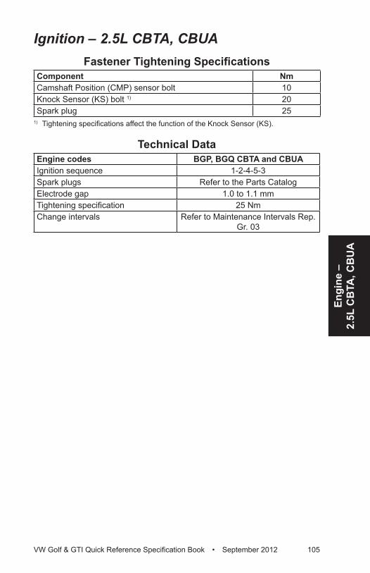
Engi
ne –
2.
5L C
BTA
, CB
UA
VW Golf & GTI Quick Reference Specification Book • September 2012 105
Ignition – 2.5L CBTA, CBUAFastener Tightening Specifications
Component NmCamshaft Position (CMP) sensor bolt 10Knock Sensor (KS) bolt 1) 20Spark plug 25
1) Tightening specifications affect the function of the Knock Sensor (KS).
Technical DataEngine codes BGP, BGQ CBTA and CBUAIgnition sequence 1-2-4-5-3Spark plugs Refer to the Parts CatalogElectrode gap 1.0 to 1.1 mmTightening specification 25 NmChange intervals Refer to Maintenance Intervals Rep.
Gr. 03
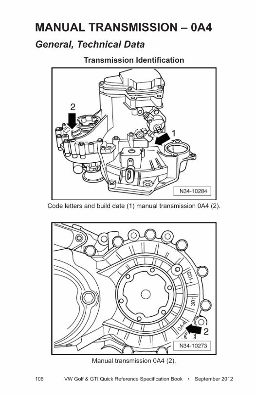
106 VW Golf & GTI Quick Reference Specification Book • September 2012
MANUAL TRANSMISSION – 0A4General, Technical Data
Transmission Identification
Code letters and build date (1) manual transmission 0A4 (2).
Manual transmission 0A4 (2).
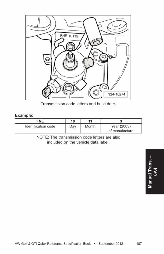
Man
ual T
rans
. –
0A4
VW Golf & GTI Quick Reference Specification Book • September 2012 107
Transmission code letters and build date.
Example:FNE 10 11 3
Identification code Day Month Year (2003) of manufacture
NOTE: The transmission code letters are also included on the vehicle data label.
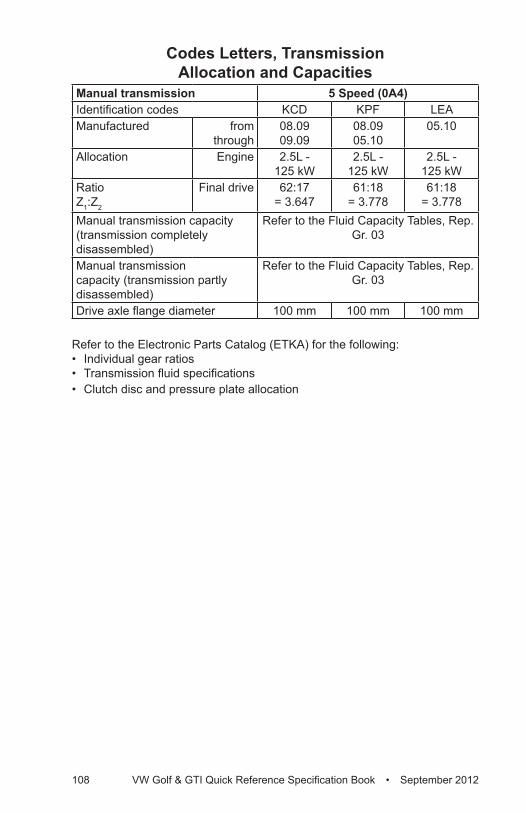
108 VW Golf & GTI Quick Reference Specification Book • September 2012
Codes Letters, Transmission Allocation and Capacities
Manual transmission 5 Speed (0A4)Identification codes KCD KPF LEAManufactured from
through08.09 09.09
08.09 05.10
05.10
Allocation Engine 2.5L - 125 kW
2.5L - 125 kW
2.5L - 125 kW
Ratio Z1:Z2
Final drive 62:17 = 3.647
61:18 = 3.778
61:18 = 3.778
Manual transmission capacity (transmission completely disassembled)
Refer to the Fluid Capacity Tables, Rep. Gr. 03
Manual transmission capacity (transmission partly disassembled)
Refer to the Fluid Capacity Tables, Rep. Gr. 03
Drive axle flange diameter 100 mm 100 mm 100 mm
Refer to the Electronic Parts Catalog (ETKA) for the following:• Individual gear ratios• Transmission fluid specifications• Clutch disc and pressure plate allocation
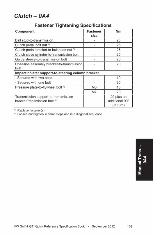
Man
ual T
rans
. –
0A4
VW Golf & GTI Quick Reference Specification Book • September 2012 109
Clutch – 0A4Fastener Tightening Specifications
Component Fastener size
Nm
Ball stud-to-transmission - 25Clutch pedal bolt nut 1) - 25Clutch pedal bracket-to-bulkhead nut 1) - 25Clutch slave cylinder-to-transmission bolt - 20Guide sleeve-to-transmission bolt - 20Hose/line assembly bracket-to-transmission bolt
- 20
Impact bolster support-to-steering column bracket- Secured with two bolts - 10- Secured with one bolt - 20Pressure plate-to-flywheel bolt 2) M6 13
M7 20Transmission support-to-transmission bracket/transmission bolt 1)
- 20 plus an additional 90°
(¼ turn)1) Replace fastener(s).
2) Loosen and tighten in small steps and in a diagonal sequence.
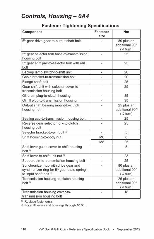
110 VW Golf & GTI Quick Reference Specification Book • September 2012
Controls, Housing – 0A4Fastener Tightening Specifications
Component Fastener size
Nm
5th gear drive gear-to-output shaft bolt - 80 plus an additional 90°
(¼ turn)5th gear selector fork base-to-transmission housing bolt
- 25
5th gear shift jaw-to-selector fork with rail bolt
- 25
Backup lamp switch-to-shift unit - 20Cable bracket-to-transmission bolt - 20Flange shaft bolt - 25Gear shift unit with selector cover-to-transmission housing bolt
- 25
Oil drain plug-to-clutch housing - 35Oil fill plug-to-transmission housing - 35Output shaft bearing mount-to-clutch housing nut 1)
- 25 plus an additional 90°
(¼ turn)Sealing cap-to-transmission housing bolt - 25Reverse gear selector fork-to-clutch housing bolt
- 25
Selector bracket-to-pin bolt 2) - 5Shift housing-to-body nut M6 8
M8 25Shift lever guide cover-to-shift housing bolt 2)
- 5
Shift lever-to-shift unit nut 1) - 23Support pin-to-transmission housing bolt - 25Synchronizer hub with drive gear and synchronizer ring for 5th gear plate spring-to-input shaft bolt 1)
- 80 plus an additional 90°
(¼ turn)Transmission housing-to-clutch housing bolt 1)
- 25 plus an additional 90°
(¼ turn)Transmission housing cover-to-transmission housing bolt
- 18
1) Replace fastener(s).
2) For shift levers and housings through 10.06.
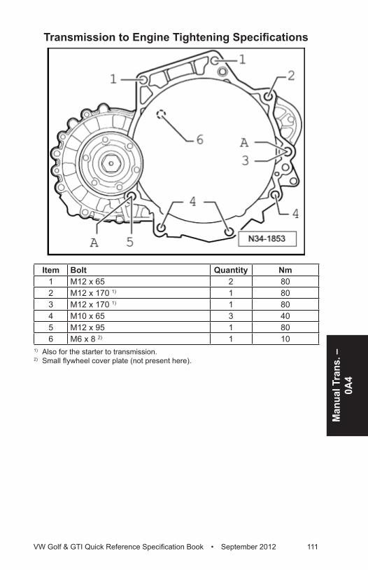
Man
ual T
rans
. –
0A4
VW Golf & GTI Quick Reference Specification Book • September 2012 111
Transmission to Engine Tightening Specifications
Item Bolt Quantity Nm1 M12 x 65 2 802 M12 x 170 1) 1 803 M12 x 170 1) 1 804 M10 x 65 3 405 M12 x 95 1 806 M6 x 8 2) 1 10
1) Also for the starter to transmission.2) Small flywheel cover plate (not present here).
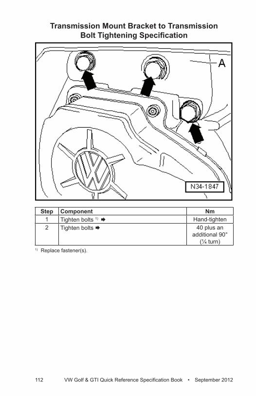
112 VW Golf & GTI Quick Reference Specification Book • September 2012
Transmission Mount Bracket to Transmission Bolt Tightening Specification
Step Component Nm1 Tighten bolts 1) Æ Hand-tighten2 Tighten bolts Æ 40 plus an
additional 90° (¼ turn)
1) Replace fastener(s).
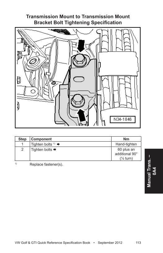
Man
ual T
rans
. –
0A4
VW Golf & GTI Quick Reference Specification Book • September 2012 113
Transmission Mount to Transmission Mount Bracket Bolt Tightening Specification
Step Component Nm1 Tighten bolts 1) Æ Hand-tighten2 Tighten bolts Æ 60 plus an
additional 90° (¼ turn)
1) Replace fastener(s).
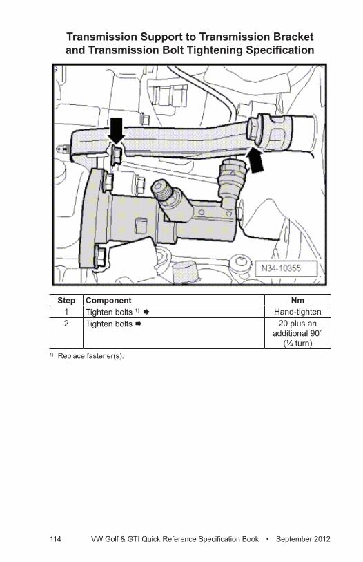
114 VW Golf & GTI Quick Reference Specification Book • September 2012
Transmission Support to Transmission Bracket and Transmission Bolt Tightening Specification
Step Component Nm1 Tighten bolts 1) Æ Hand-tighten2 Tighten bolts Æ 20 plus an
additional 90° (¼ turn)
1) Replace fastener(s).
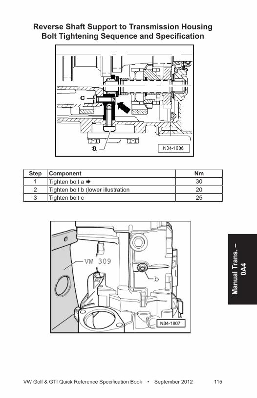
Man
ual T
rans
. –
0A4
VW Golf & GTI Quick Reference Specification Book • September 2012 115
Reverse Shaft Support to Transmission Housing Bolt Tightening Sequence and Specification
Step Component Nm1 Tighten bolt a Æ 302 Tighten bolt b (lower illustration 203 Tighten bolt c 25
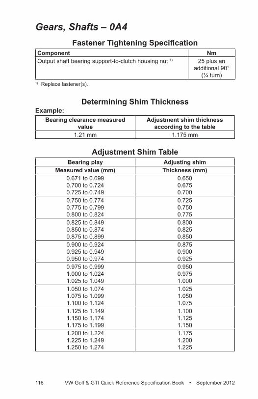
116 VW Golf & GTI Quick Reference Specification Book • September 2012
Gears, Shafts – 0A4Fastener Tightening Specification
Component NmOutput shaft bearing support-to-clutch housing nut 1) 25 plus an
additional 90° (¼ turn)
1) Replace fastener(s).
Determining Shim ThicknessExample:
Bearing clearance measured value
Adjustment shim thickness according to the table
1.21 mm 1.175 mm
Adjustment Shim TableBearing play Adjusting shim
Measured value (mm) Thickness (mm)0.671 to 0.699 0.700 to 0.724 0.725 to 0.749
0.650 0.675 0.700
0.750 to 0.774 0.775 to 0.799 0.800 to 0.824
0.725 0.750 0.775
0.825 to 0.849 0.850 to 0.874 0.875 to 0.899
0.800 0.825 0.850
0.900 to 0.924 0.925 to 0.949 0.950 to 0.974
0.875 0.900 0.925
0.975 to 0.999 1.000 to 1.024 1.025 to 1.049
0.950 0.975 1.000
1.050 to 1.074 1.075 to 1.099 1.100 to 1.124
1.025 1.050 1.075
1.125 to 1.149 1.150 to 1.174 1.175 to 1.199
1.100 1.125 1.150
1.200 to 1.224 1.225 to 1.249 1.250 to 1.274
1.175 1.200 1.225
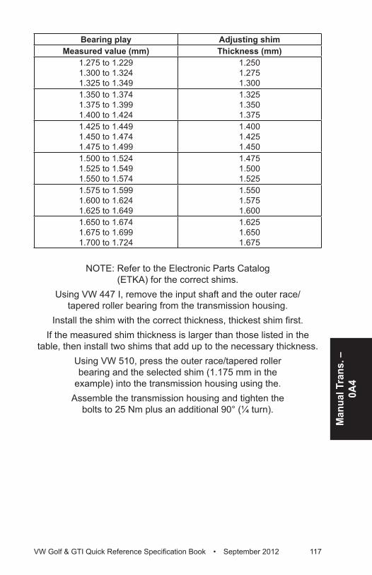
Man
ual T
rans
. –
0A4
VW Golf & GTI Quick Reference Specification Book • September 2012 117
Bearing play Adjusting shimMeasured value (mm) Thickness (mm)
1.275 to 1.229 1.300 to 1.324 1.325 to 1.349
1.250 1.275 1.300
1.350 to 1.374 1.375 to 1.399 1.400 to 1.424
1.325 1.350 1.375
1.425 to 1.449 1.450 to 1.474 1.475 to 1.499
1.400 1.425 1.450
1.500 to 1.524 1.525 to 1.549 1.550 to 1.574
1.475 1.500 1.525
1.575 to 1.599 1.600 to 1.624 1.625 to 1.649
1.550 1.575 1.600
1.650 to 1.674 1.675 to 1.699 1.700 to 1.724
1.625 1.650 1.675
NOTE: Refer to the Electronic Parts Catalog (ETKA) for the correct shims.
Using VW 447 I, remove the input shaft and the outer race/tapered roller bearing from the transmission housing.
Install the shim with the correct thickness, thickest shim first.If the measured shim thickness is larger than those listed in the
table, then install two shims that add up to the necessary thickness.Using VW 510, press the outer race/tapered roller bearing and the selected shim (1.175 mm in the
example) into the transmission housing using the.Assemble the transmission housing and tighten the
bolts to 25 Nm plus an additional 90° (¼ turn).
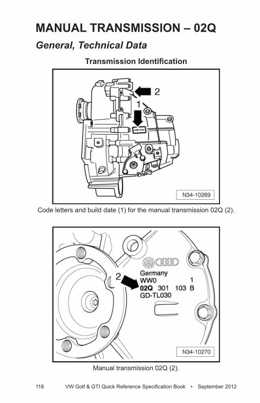
118 VW Golf & GTI Quick Reference Specification Book • September 2012
MANUAL TRANSMISSION – 02QGeneral, Technical Data
Transmission Identification
Code letters and build date (1) for the manual transmission 02Q (2).
Manual transmission 02Q (2).
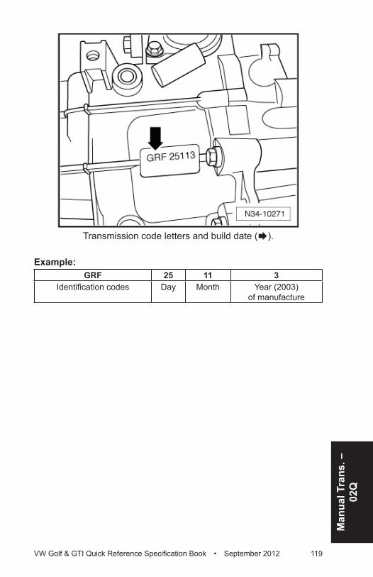
Man
ual T
rans
. –
02Q
VW Golf & GTI Quick Reference Specification Book • September 2012 119
Transmission code letters and build date (Æ).
Example:GRF 25 11 3
Identification codes Day Month Year (2003) of manufacture
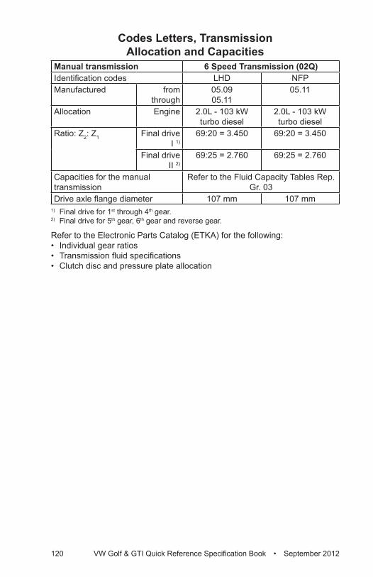
120 VW Golf & GTI Quick Reference Specification Book • September 2012
Codes Letters, Transmission Allocation and Capacities
Manual transmission 6 Speed Transmission (02Q)Identification codes LHD NFPManufactured from
through05.09 05.11
05.11
Allocation Engine 2.0L - 103 kW turbo diesel
2.0L - 103 kW turbo diesel
Ratio: Z2: Z1 Final drive I 1)
69:20 = 3.450 69:20 = 3.450
Final drive II 2)
69:25 = 2.760 69:25 = 2.760
Capacities for the manual transmission
Refer to the Fluid Capacity Tables Rep. Gr. 03
Drive axle flange diameter 107 mm 107 mm1) Final drive for 1st through 4th gear. 2) Final drive for 5th gear, 6th gear and reverse gear.
Refer to the Electronic Parts Catalog (ETKA) for the following:• Individual gear ratios• Transmission fluid specifications• Clutch disc and pressure plate allocation
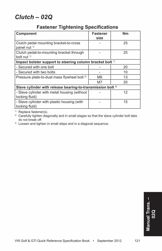
Man
ual T
rans
. –
02Q
VW Golf & GTI Quick Reference Specification Book • September 2012 121
Clutch – 02QFastener Tightening Specifications
Component Fastener size
Nm
Clutch pedal mounting bracket-to-cross panel nut 1)
- 25
Clutch pedal-to-mounting bracket through bolt nut 1)
- 25
Impact bolster support to steering column bracket bolt 1)
- Secured with one bolt - 20- Secured with two bolts - 10Pressure plate-to-dual mass flywheel bolt 2) M6 13
M7 20Slave cylinder with release bearing-to-transmission bolt 1)
- Slave cylinder with metal housing (without locking fluid)
- 12
- Slave cylinder with plastic housing (with locking fluid)
- 15
1) Replace fastener(s).2) Carefully tighten diagonally and in small stages so that the slave cylinder bolt tabs
do not break off.3) Loosen and tighten in small steps and in a diagonal sequence.
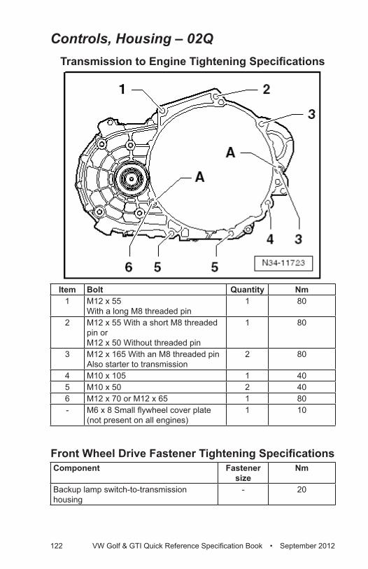
122 VW Golf & GTI Quick Reference Specification Book • September 2012
Controls, Housing – 02QTransmission to Engine Tightening Specifications
Item Bolt Quantity Nm1 M12 x 55
With a long M8 threaded pin1 80
2 M12 x 55 With a short M8 threaded pin or M12 x 50 Without threaded pin
1 80
3 M12 x 165 With an M8 threaded pinAlso starter to transmission
2 80
4 M10 x 105 1 405 M10 x 50 2 406 M12 x 70 or M12 x 65 1 80- M6 x 8 Small flywheel cover plate
(not present on all engines)1 10
Front Wheel Drive Fastener Tightening SpecificationsComponent Fastener
sizeNm
Backup lamp switch-to-transmission housing
- 20
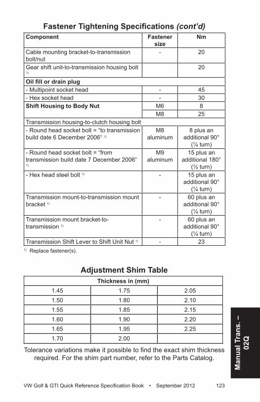
Man
ual T
rans
. –
02Q
VW Golf & GTI Quick Reference Specification Book • September 2012 123
Component Fastener size
Nm
Cable mounting bracket-to-transmission bolt/nut
- 20
Gear shift unit-to-transmission housing bolt 1)
20
Oil fill or drain plug- Multipoint socket head - 45- Hex socket head - 30Shift Housing to Body Nut M6 8
M8 25Transmission housing-to-clutch housing bolt- Round head socket bolt = “to transmission build date 6 December 2006“ 1)
M8 aluminum
8 plus an additional 90°
(¼ turn)- Round head socket bolt = “from transmission build date 7 December 2006“ 1)
M9 aluminum
15 plus an additional 180°
(½ turn)- Hex head steel bolt 1) - 15 plus an
additional 90° (¼ turn)
Transmission mount-to-transmission mount bracket 1)
- 60 plus an additional 90°
(¼ turn)Transmission mount bracket-to-transmission 1)
- 60 plus an additional 90°
(¼ turn)Transmission Shift Lever to Shift Unit Nut 1) - 23
1) Replace fastener(s).
Adjustment Shim TableThickness in (mm)
1.45 1.75 2.051.50 1.80 2.101.55 1.85 2.151.60 1.90 2.201.65 1.95 2.251.70 2.00
Tolerance variations make it possible to find the exact shim thickness required. For the shim part number, refer to the Parts Catalog.
Fastener Tightening Specifications (cont’d)
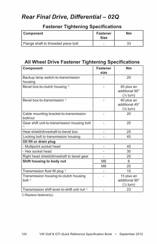
124 VW Golf & GTI Quick Reference Specification Book • September 2012
Rear Final Drive, Differential – 02QFastener Tightening Specifications
Component Fastener Size
Nm
Flange shaft to threaded piece bolt - 33
All Wheel Drive Fastener Tightening SpecificationsComponent Fastener
sizeNm
Backup lamp switch-to-transmission housing
- 20
Bevel box-to-clutch housing 1) - 40 plus an additional 90°
(¼ turn)Bevel box-to-transmission 1) - 40 plus an
additional 45° (⅛ turn)
Cable mounting bracket-to-transmission bolt/nut
- 20
Gear shift unit-to-transmission housing bolt 1)
- 20
Heat shield/driveshaft-to-bevel box - 25Locking bolt to transmission housing - 45Oil fill or drain plug- Multipoint socket head - 45- Hex socket head - 30Right head shield/driveshaft to bevel gear - 20Shift housing to body nut M6 8
M8 25Transmission fluid fill plug 1) - 15Transmission housing-to-clutch housing bolt 1)
- 15 plus an additional 90°
(¼ turn)Transmission shift lever-to-shift unit nut 1) - 23
1) Replace fastener(s).
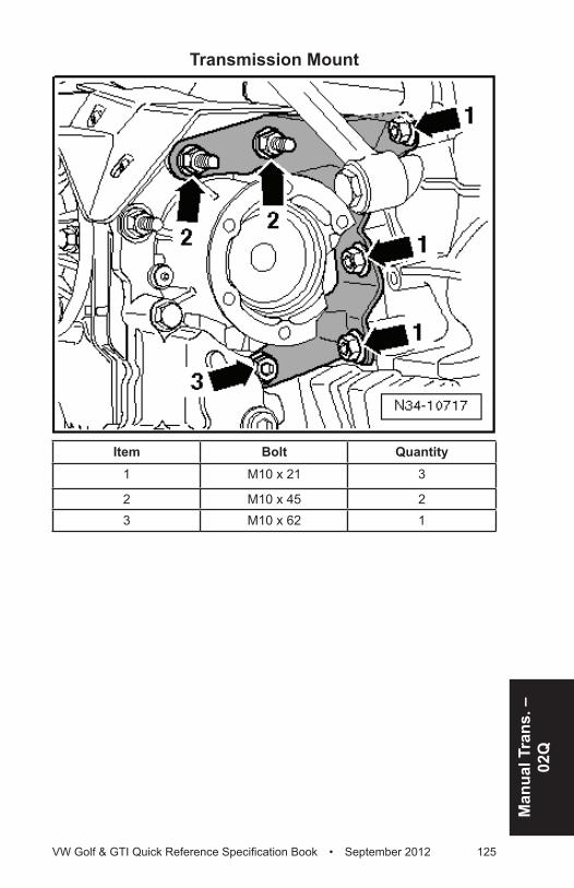
Man
ual T
rans
. –
02Q
VW Golf & GTI Quick Reference Specification Book • September 2012 125
Transmission Mount
Item Bolt Quantity1 M10 x 21 3
2 M10 x 45 23 M10 x 62 1
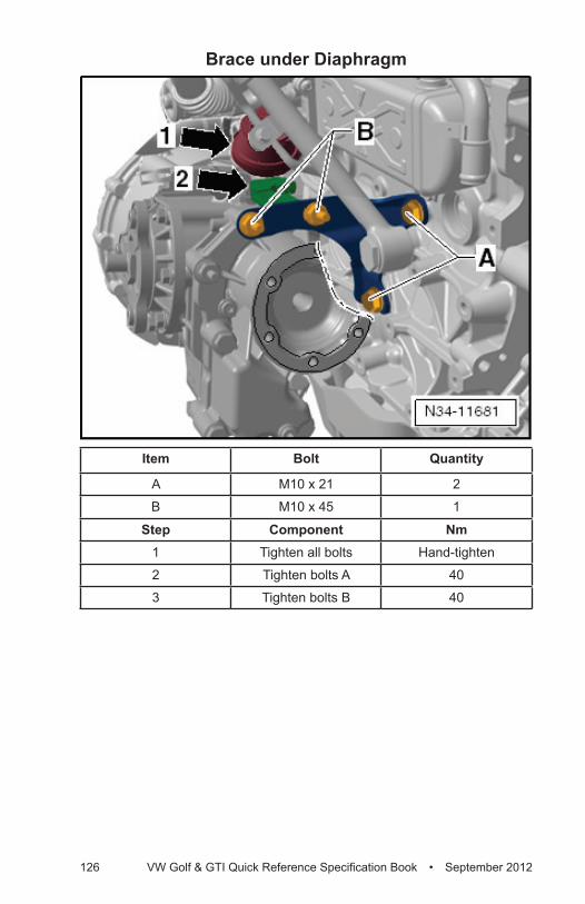
126 VW Golf & GTI Quick Reference Specification Book • September 2012
Brace under Diaphragm
Item Bolt Quantity
A M10 x 21 2
B M10 x 45 1
Step Component Nm1 Tighten all bolts Hand-tighten
2 Tighten bolts A 40
3 Tighten bolts B 40
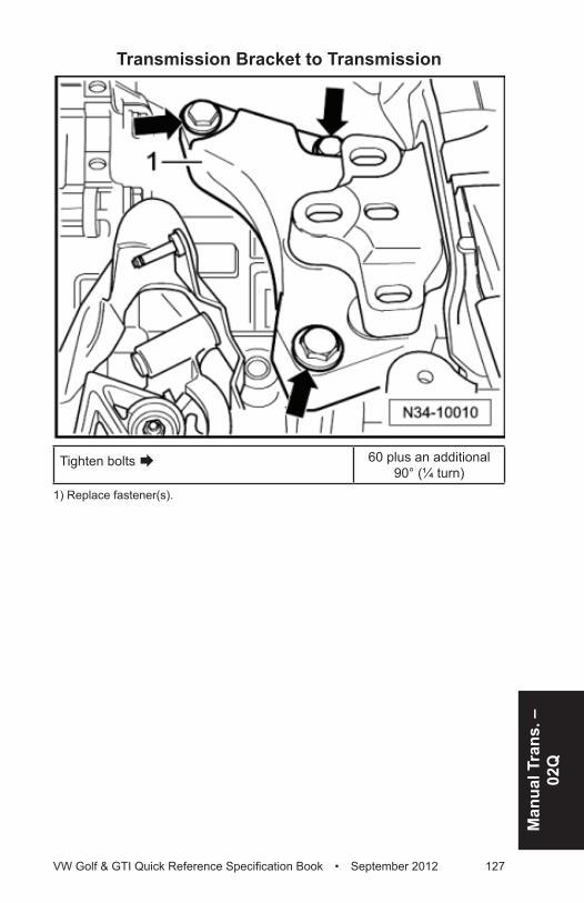
Man
ual T
rans
. –
02Q
VW Golf & GTI Quick Reference Specification Book • September 2012 127
Transmission Bracket to Transmission
Tighten bolts Æ 60 plus an additional 90° (¼ turn)
1) Replace fastener(s).
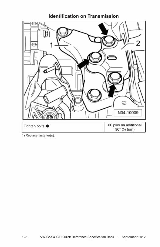
128 VW Golf & GTI Quick Reference Specification Book • September 2012
Identification on Transmission
Tighten bolts Æ 60 plus an additional 90° (¼ turn)
1) Replace fastener(s).
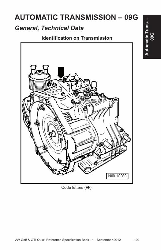
Auto
mat
ic T
rans
. –
09G
VW Golf & GTI Quick Reference Specification Book • September 2012 129
AUTOMATIC TRANSMISSION – 09GGeneral, Technical Data
Identification on Transmission
Code letters (Æ).
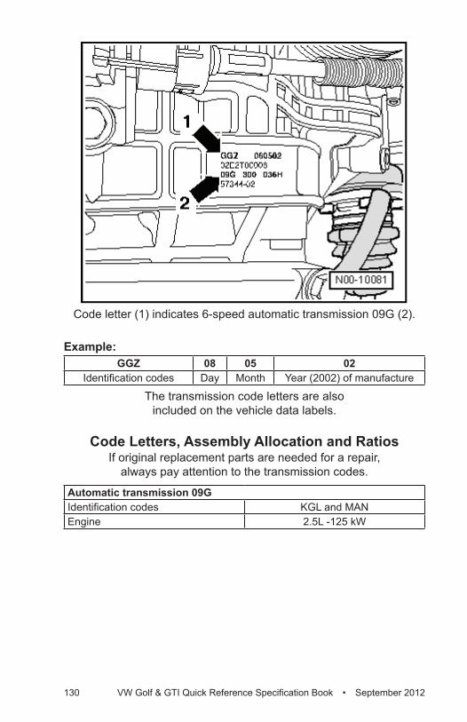
130 VW Golf & GTI Quick Reference Specification Book • September 2012
Code letter (1) indicates 6-speed automatic transmission 09G (2). Example:
GGZ 08 05 02Identification codes Day Month Year (2002) of manufacture
The transmission code letters are also included on the vehicle data labels.
Code Letters, Assembly Allocation and RatiosIf original replacement parts are needed for a repair,
always pay attention to the transmission codes.
Automatic transmission 09GIdentification codes KGL and MANEngine 2.5L -125 kW
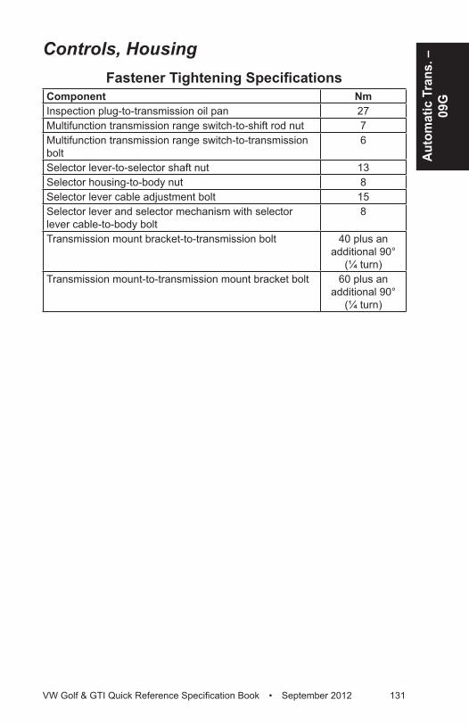
Auto
mat
ic T
rans
. –
09G
VW Golf & GTI Quick Reference Specification Book • September 2012 131
Controls, HousingFastener Tightening Specifications
Component NmInspection plug-to-transmission oil pan 27Multifunction transmission range switch-to-shift rod nut 7Multifunction transmission range switch-to-transmission bolt
6
Selector lever-to-selector shaft nut 13Selector housing-to-body nut 8Selector lever cable adjustment bolt 15Selector lever and selector mechanism with selector lever cable-to-body bolt
8
Transmission mount bracket-to-transmission bolt 40 plus an additional 90°
(¼ turn)Transmission mount-to-transmission mount bracket bolt 60 plus an
additional 90° (¼ turn)

132 VW Golf & GTI Quick Reference Specification Book • September 2012
Transmission to Engine Tightening Specifications
Component Fastener size
Nm
Drive plate-to-converter - 60Bolts M12 80 or 65, if
using T10179Bolts located in the lower flange M10 40Æ Alignment pins for centering
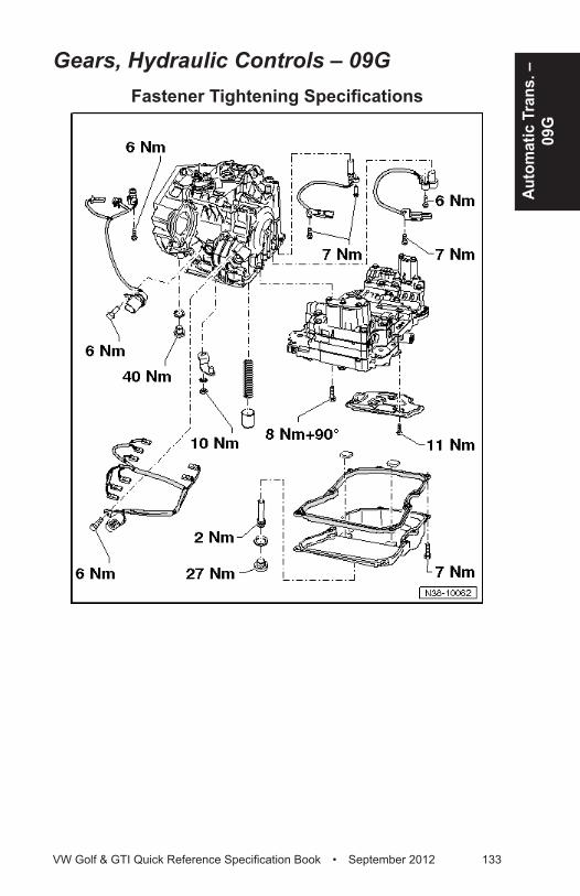
Auto
mat
ic T
rans
. –
09G
VW Golf & GTI Quick Reference Specification Book • September 2012 133
Gears, Hydraulic Controls – 09GFastener Tightening Specifications
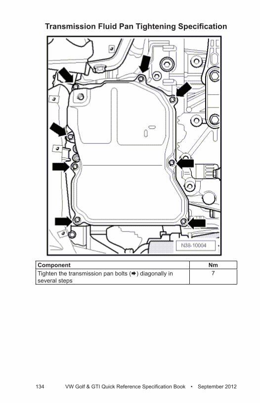
134 VW Golf & GTI Quick Reference Specification Book • September 2012
Transmission Fluid Pan Tightening Specification
Component NmTighten the transmission pan bolts (Æ) diagonally in several steps
7
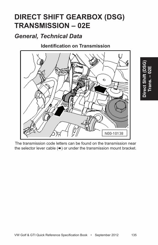
Dire
ct S
hift
(DSG
) Tr
ans.
– 0
2E
VW Golf & GTI Quick Reference Specification Book • September 2012 135
DIRECT SHIFT GEARBOx (DSG) TRANSMISSION – 02EGeneral, Technical Data
Identification on Transmission
The transmission code letters can be found on the transmission near the selector lever cable (Æ) or under the transmission mount bracket.
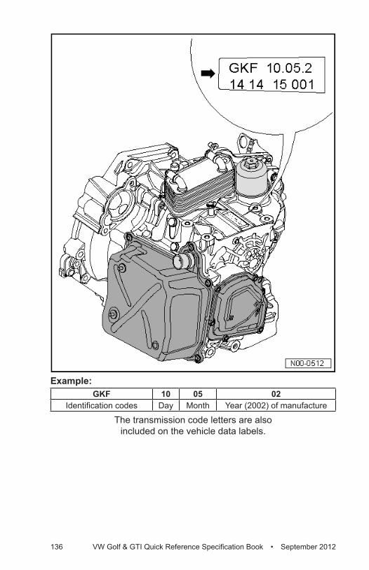
136 VW Golf & GTI Quick Reference Specification Book • September 2012
Example:GKF 10 05 02
Identification codes Day Month Year (2002) of manufacture
The transmission code letters are also included on the vehicle data labels.
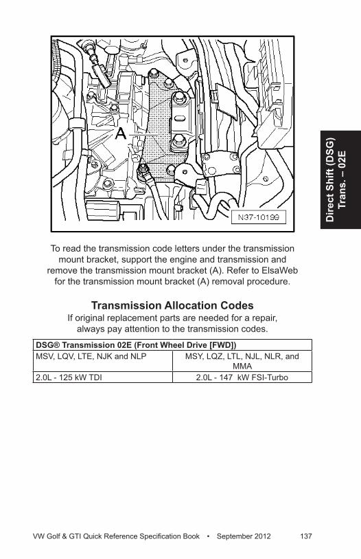
Dire
ct S
hift
(DSG
) Tr
ans.
– 0
2E
VW Golf & GTI Quick Reference Specification Book • September 2012 137
To read the transmission code letters under the transmission mount bracket, support the engine and transmission and
remove the transmission mount bracket (A). Refer to ElsaWeb for the transmission mount bracket (A) removal procedure.
Transmission Allocation CodesIf original replacement parts are needed for a repair,
always pay attention to the transmission codes.
DSG® Transmission 02E (Front Wheel Drive [FWD])MSV, LQV, LTE, NJK and NLP MSY, LQZ, LTL, NJL, NLR, and
MMA2.0L - 125 kW TDI 2.0L - 147 kW FSI-Turbo

138 VW Golf & GTI Quick Reference Specification Book • September 2012
Controls, Housing (DSG) – 02EFastener Tightening Specifications
Component NmBevel box-to-transmission bolt 2) 40Drive axle heat shield-to-bevel box bolt 2) 25Mechatronic cover bolt 1) 16Oil filter housing 20Oil pump cover bolt 1) 8Overflow tube-to-transmission 3Selector housing-to-body nut 8Selector lever cable adjustment bolt 13Selector mechanism with selector lever and selector lever cable-to-body bolt
8
Selector shaft lever nut 20Transmission drain plug 45Transmission input speed and clutch oil temperature sensor bolt
10
Transmission oil cooler-to-transmission bolt 20 plus an additional 90°
(¼ turn)Wire bracket-to-Mechatronic cover nut 10
1) Tighten the bolts diagonally and in multiple stages.2) R32 models only.
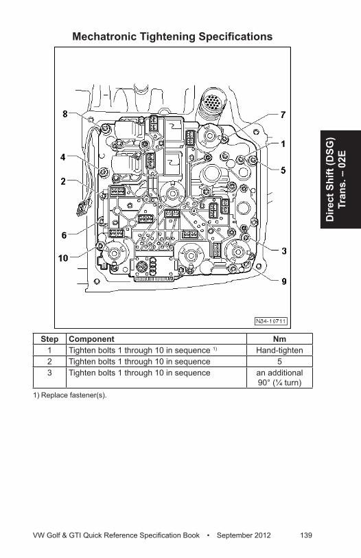
Dire
ct S
hift
(DSG
) Tr
ans.
– 0
2E
VW Golf & GTI Quick Reference Specification Book • September 2012 139
Mechatronic Tightening Specifications
Step Component Nm1 Tighten bolts 1 through 10 in sequence 1) Hand-tighten2 Tighten bolts 1 through 10 in sequence 53 Tighten bolts 1 through 10 in sequence an additional
90° (¼ turn)1) Replace fastener(s).
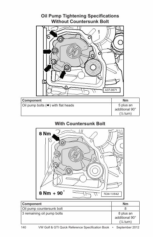
140 VW Golf & GTI Quick Reference Specification Book • September 2012
Oil Pump Tightening Specifications Without Countersunk Bolt
Component NmOil pump bolts (Æ) with flat heads 5 plus an
additional 90° (¼ turn)
With Countersunk Bolt
Component NmOil pump countersunk bolt 83 remaining oil pump bolts 8 plus an
additional 90° (¼ turn)
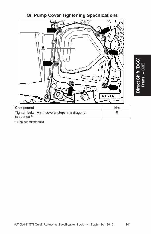
Dire
ct S
hift
(DSG
) Tr
ans.
– 0
2E
VW Golf & GTI Quick Reference Specification Book • September 2012 141
Oil Pump Cover Tightening Specifications
Component NmTighten bolts (Æ) in several steps in a diagonal sequence 1)
8
1) Replace fastener(s).
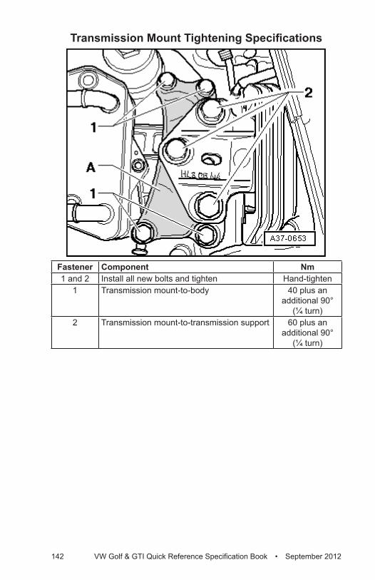
142 VW Golf & GTI Quick Reference Specification Book • September 2012
Transmission Mount Tightening Specifications
Fastener Component Nm1 and 2 Install all new bolts and tighten Hand-tighten
1 Transmission mount-to-body 40 plus an additional 90°
(¼ turn)2 Transmission mount-to-transmission support 60 plus an
additional 90° (¼ turn)
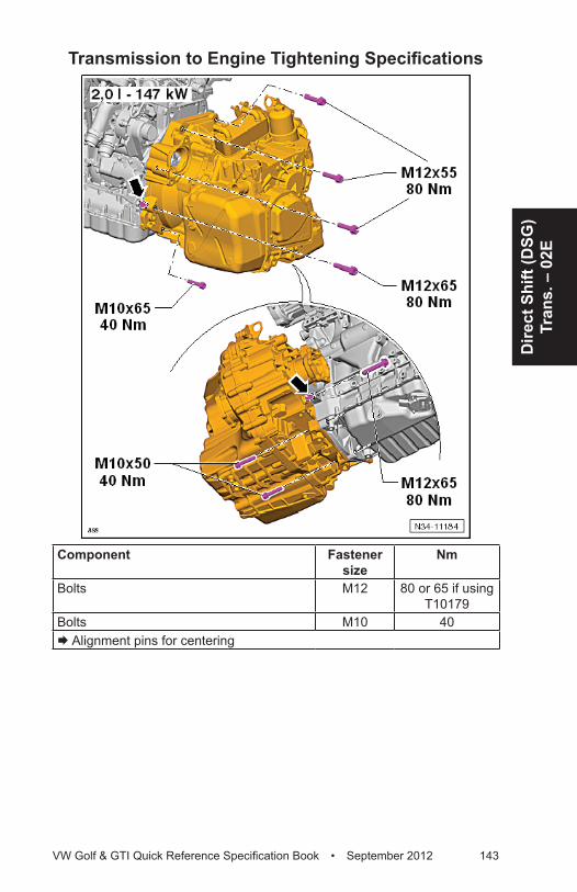
Dire
ct S
hift
(DSG
) Tr
ans.
– 0
2E
VW Golf & GTI Quick Reference Specification Book • September 2012 143
Transmission to Engine Tightening Specifications
Component Fastener size
Nm
Bolts M12 80 or 65 if using T10179
Bolts M10 40Æ Alignment pins for centering
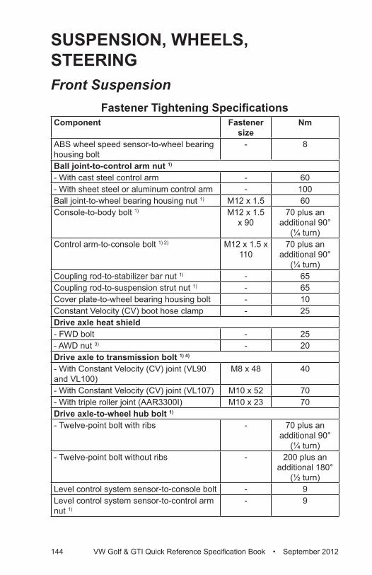
144 VW Golf & GTI Quick Reference Specification Book • September 2012
SUSPENSION, WHEELS, STEERINGFront Suspension
Fastener Tightening SpecificationsComponent Fastener
sizeNm
ABS wheel speed sensor-to-wheel bearing housing bolt
- 8
Ball joint-to-control arm nut 1)
- With cast steel control arm - 60- With sheet steel or aluminum control arm - 100Ball joint-to-wheel bearing housing nut 1) M12 x 1.5 60Console-to-body bolt 1) M12 x 1.5
x 9070 plus an
additional 90° (¼ turn)
Control arm-to-console bolt 1) 2) M12 x 1.5 x 110
70 plus an additional 90°
(¼ turn)Coupling rod-to-stabilizer bar nut 1) - 65Coupling rod-to-suspension strut nut 1) - 65Cover plate-to-wheel bearing housing bolt - 10Constant Velocity (CV) boot hose clamp - 25Drive axle heat shield- FWD bolt - 25- AWD nut 3) - 20Drive axle to transmission bolt 1) 4)
- With Constant Velocity (CV) joint (VL90 and VL100)
M8 x 48 40
- With Constant Velocity (CV) joint (VL107) M10 x 52 70- With triple roller joint (AAR3300I) M10 x 23 70Drive axle-to-wheel hub bolt 1)
- Twelve-point bolt with ribs - 70 plus an additional 90°
(¼ turn)- Twelve-point bolt without ribs - 200 plus an
additional 180° (½ turn)
Level control system sensor-to-console bolt - 9Level control system sensor-to-control arm nut 1)
- 9
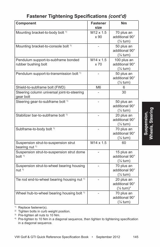
Susp
ensi
on,
Whe
els,
Ste
erin
g
VW Golf & GTI Quick Reference Specification Book • September 2012 145
Component Fastener size
Nm
Mounting bracket-to-body bolt 1) M12 x 1.5 x 90
70 plus an additional 90°
(¼ turn)Mounting bracket-to-console bolt 1) - 50 plus an
additional 90° (¼ turn)
Pendulum support-to-subframe bonded rubber bushing bolt
M14 x 1.5 x 70
100 plus an additional 90°
(¼ turn)Pendulum support-to-transmission bolt 1) - 50 plus an
additional 90° (¼ turn)
Shield-to-subframe bolt (FWD) M6 6Steering column universal joint-to-steering gear bolt
- 30
Steering gear-to-subframe bolt 1) - 50 plus an additional 90°
(¼ turn)Stabilizer bar-to-subframe bolt 1) - 20 plus an
additional 90° (¼ turn)
Subframe-to-body bolt 1) - 70 plus an additional 90°
(¼ turn)Suspension strut-to-suspension strut bearing nut 1)
M14 x 1.5 60
Suspension strut-to-suspension strut dome bolt 1)
- 15 plus an additional 90°
(¼ turn)Suspension strut-to-wheel bearing housing nut 1)
- 70 plus an additional 90°
(¼ turn)Tie rod end-to-wheel bearing housing nut 1) - 20 plus an
additional 90° (¼ turn)°
Wheel hub-to-wheel bearing housing bolt 1) - 70 plus an additional 90°
(¼ turn)1) Replace fastener(s).2) Tighten bolts in curb weight position.3) Pre-tighten all nuts to 10 Nm.4) Pre-tighten to 10 Nm in a diagonal sequence, then tighten to tightening specification
in a diagonal sequence.
Fastener Tightening Specifications (cont’d)
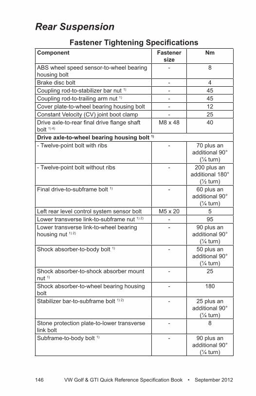
146 VW Golf & GTI Quick Reference Specification Book • September 2012
Rear SuspensionFastener Tightening Specifications
Component Fastener size
Nm
ABS wheel speed sensor-to-wheel bearing housing bolt
- 8
Brake disc bolt - 4Coupling rod-to-stabilizer bar nut 1) - 45Coupling rod-to-trailing arm nut 1) - 45Cover plate-to-wheel bearing housing bolt - 12Constant Velocity (CV) joint boot clamp - 25Drive axle-to-rear final drive flange shaft bolt 1) 4)
M8 x 48 40
Drive axle-to-wheel bearing housing bolt 1)
- Twelve-point bolt with ribs - 70 plus an additional 90°
(¼ turn)- Twelve-point bolt without ribs - 200 plus an
additional 180° (½ turn)
Final drive-to-subframe bolt 1) - 60 plus an additional 90°
(¼ turn)Left rear level control system sensor bolt M5 x 20 5Lower transverse link-to-subframe nut 1) 2) - 95Lower transverse link-to-wheel bearing housing nut 1) 2)
- 90 plus an additional 90°
(¼ turn)Shock absorber-to-body bolt 1) - 50 plus an
additional 90° (¼ turn)
Shock absorber-to-shock absorber mount nut 1)
- 25
Shock absorber-to-wheel bearing housing bolt
- 180
Stabilizer bar-to-subframe bolt 1) 2) - 25 plus an additional 90°
(¼ turn)Stone protection plate-to-lower transverse link bolt
- 8
Subframe-to-body bolt 1) - 90 plus an additional 90°
(¼ turn)
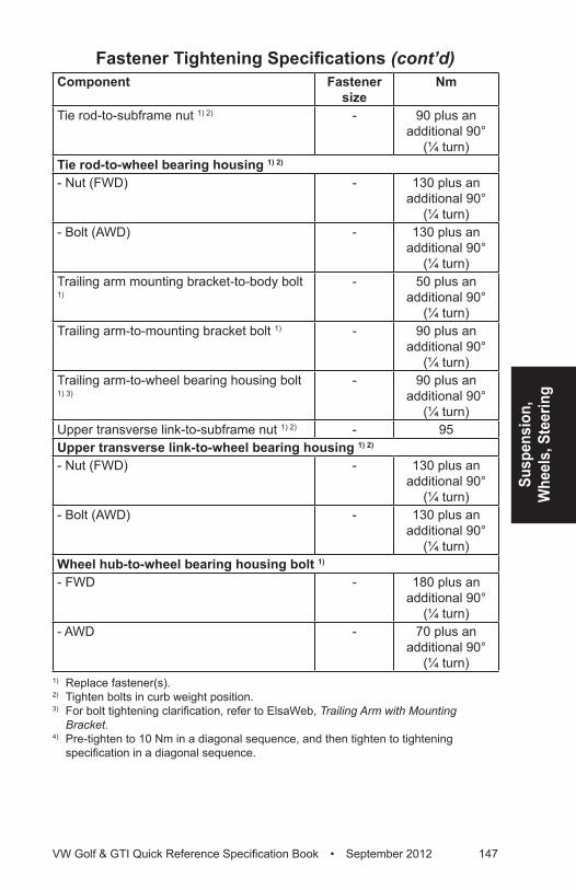
Susp
ensi
on,
Whe
els,
Ste
erin
g
VW Golf & GTI Quick Reference Specification Book • September 2012 147
Component Fastener size
Nm
Tie rod-to-subframe nut 1) 2) - 90 plus an additional 90°
(¼ turn)Tie rod-to-wheel bearing housing 1) 2)
- Nut (FWD) - 130 plus an additional 90°
(¼ turn)- Bolt (AWD) - 130 plus an
additional 90° (¼ turn)
Trailing arm mounting bracket-to-body bolt 1)
- 50 plus an additional 90°
(¼ turn)Trailing arm-to-mounting bracket bolt 1) - 90 plus an
additional 90° (¼ turn)
Trailing arm-to-wheel bearing housing bolt 1) 3)
- 90 plus an additional 90°
(¼ turn)Upper transverse link-to-subframe nut 1) 2) - 95Upper transverse link-to-wheel bearing housing 1) 2)
- Nut (FWD) - 130 plus an additional 90°
(¼ turn)- Bolt (AWD) - 130 plus an
additional 90° (¼ turn)
Wheel hub-to-wheel bearing housing bolt 1)
- FWD - 180 plus an additional 90°
(¼ turn)- AWD - 70 plus an
additional 90° (¼ turn)
1) Replace fastener(s).2) Tighten bolts in curb weight position.3) For bolt tightening clarification, refer to ElsaWeb, Trailing Arm with Mounting
Bracket.4) Pre-tighten to 10 Nm in a diagonal sequence, and then tighten to tightening
specification in a diagonal sequence.
Fastener Tightening Specifications (cont’d)
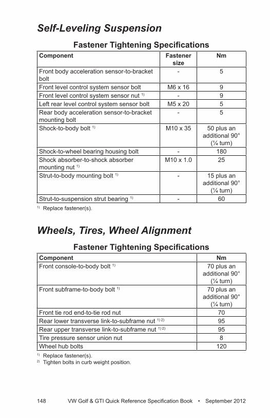
148 VW Golf & GTI Quick Reference Specification Book • September 2012
Self-Leveling SuspensionFastener Tightening Specifications
Component Fastener size
Nm
Front body acceleration sensor-to-bracket bolt
- 5
Front level control system sensor bolt M6 x 16 9Front level control system sensor nut 1) - 9Left rear level control system sensor bolt M5 x 20 5Rear body acceleration sensor-to-bracket mounting bolt
- 5
Shock-to-body bolt 1) M10 x 35 50 plus an additional 90°
(¼ turn)Shock-to-wheel bearing housing bolt - 180Shock absorber-to-shock absorber mounting nut 1)
M10 x 1.0 25
Strut-to-body mounting bolt 1) - 15 plus an additional 90°
(¼ turn) Strut-to-suspension strut bearing 1) - 60
1) Replace fastener(s).
Wheels, Tires, Wheel AlignmentFastener Tightening Specifications
Component NmFront console-to-body bolt 1) 70 plus an
additional 90° (¼ turn)
Front subframe-to-body bolt 1) 70 plus an additional 90°
(¼ turn)Front tie rod end-to-tie rod nut 70Rear lower transverse link-to-subframe nut 1) 2) 95Rear upper transverse link-to-subframe nut 1) 2) 95Tire pressure sensor union nut 8Wheel hub bolts 120
1) Replace fastener(s).2) Tighten bolts in curb weight position.
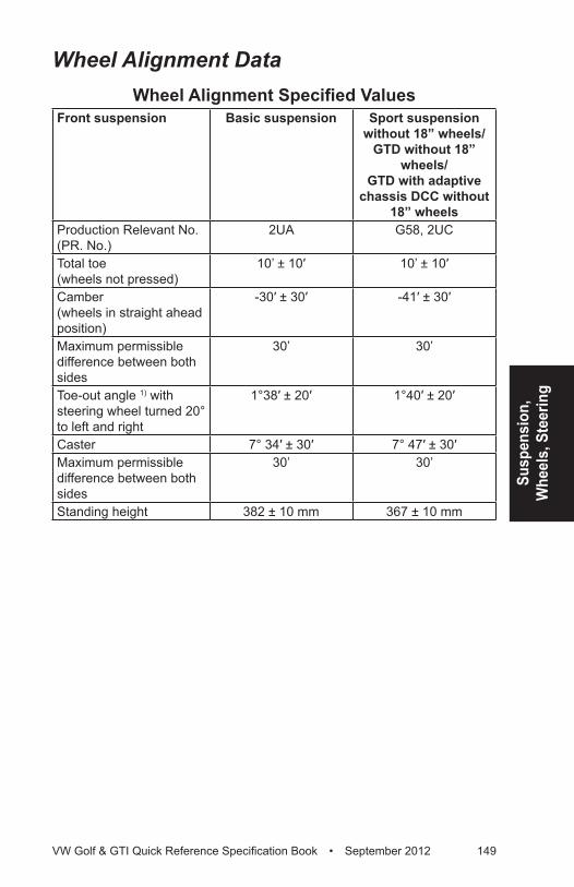
Susp
ensi
on,
Whe
els,
Ste
erin
g
VW Golf & GTI Quick Reference Specification Book • September 2012 149
Wheel Alignment DataWheel Alignment Specified Values
Front suspension Basic suspension Sport suspension without 18” wheels/
GTD without 18” wheels/
GTD with adaptive chassis DCC without
18” wheelsProduction Relevant No. (PR. No.)
2UA G58, 2UC
Total toe (wheels not pressed)
10’ ± 10′ 10’ ± 10′
Camber (wheels in straight ahead position)
-30′ ± 30′ -41′ ± 30′
Maximum permissible difference between both sides
30’ 30’
Toe-out angle 1) with steering wheel turned 20° to left and right
1°38′ ± 20′ 1°40′ ± 20′
Caster 7° 34′ ± 30′ 7° 47′ ± 30′Maximum permissible difference between both sides
30’ 30’
Standing height 382 ± 10 mm 367 ± 10 mm
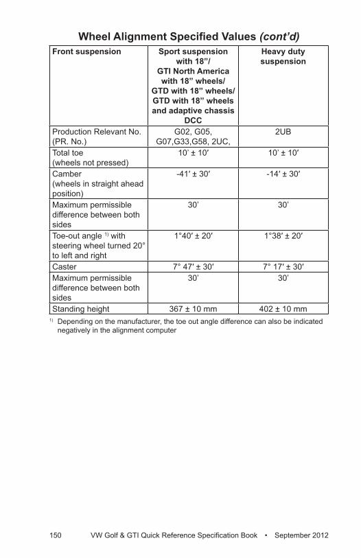
150 VW Golf & GTI Quick Reference Specification Book • September 2012
Front suspension Sport suspension with 18”/
GTI North America with 18” wheels/
GTD with 18” wheels/ GTD with 18” wheels and adaptive chassis
DCC
Heavy duty suspension
Production Relevant No. (PR. No.)
G02, G05, G07,G33,G58, 2UC,
2UB
Total toe (wheels not pressed)
10’ ± 10′ 10’ ± 10′
Camber (wheels in straight ahead position)
-41′ ± 30′ -14′ ± 30′
Maximum permissible difference between both sides
30’ 30’
Toe-out angle 1) with steering wheel turned 20° to left and right
1°40′ ± 20′ 1°38′ ± 20′
Caster 7° 47′ ± 30′ 7° 17′ ± 30′Maximum permissible difference between both sides
30’ 30’
Standing height 367 ± 10 mm 402 ± 10 mm1) Depending on the manufacturer, the toe out angle difference can also be indicated
negatively in the alignment computer
Wheel Alignment Specified Values (cont’d)
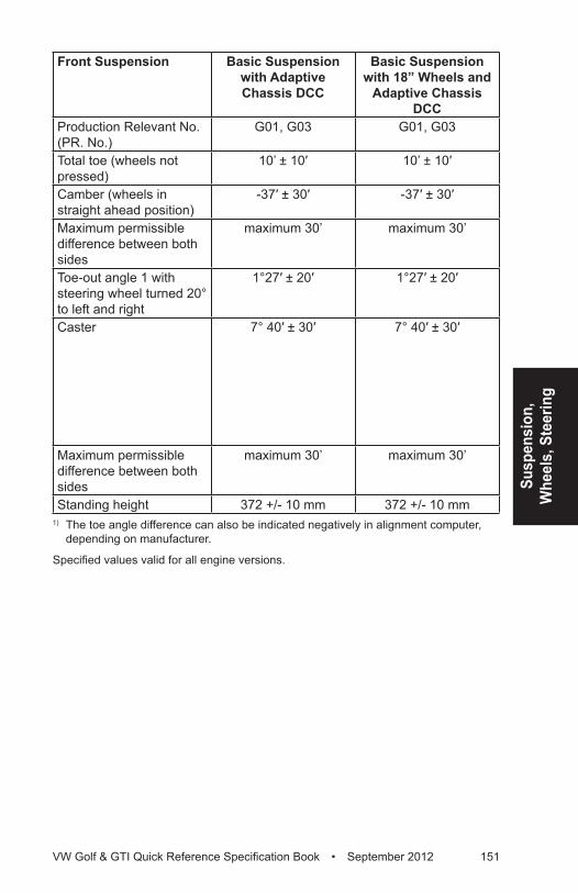
Susp
ensi
on,
Whe
els,
Ste
erin
g
VW Golf & GTI Quick Reference Specification Book • September 2012 151
Front Suspension Basic Suspension with Adaptive Chassis DCC
Basic Suspension with 18” Wheels and
Adaptive Chassis DCC
Production Relevant No. (PR. No.)
G01, G03 G01, G03
Total toe (wheels not pressed)
10’ ± 10′ 10’ ± 10′
Camber (wheels in straight ahead position)
-37′ ± 30′ -37′ ± 30′
Maximum permissible difference between both sides
maximum 30’ maximum 30’
Toe-out angle 1 with steering wheel turned 20° to left and right
1°27′ ± 20′ 1°27′ ± 20′
Caster 7° 40′ ± 30′ 7° 40′ ± 30′
Maximum permissible difference between both sides
maximum 30’ maximum 30’
Standing height 372 +/- 10 mm 372 +/- 10 mm1) The toe angle difference can also be indicated negatively in alignment computer,
depending on manufacturer.
Specified values valid for all engine versions.
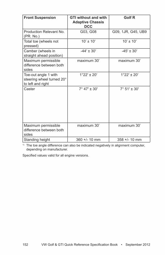
152 VW Golf & GTI Quick Reference Specification Book • September 2012
Front Suspension GTI without and with Adaptive Chassis
DCC
Golf R
Production Relevant No. (PR. No.)
G03, G08 G09, 1JR, G45, UB9
Total toe (wheels not pressed)
10’ ± 10′ 10’ ± 10′
Camber (wheels in straight ahead position)
-44′ ± 30′ -45′ ± 30′
Maximum permissible difference between both sides
maximum 30’ maximum 30’
Toe-out angle 1 with steering wheel turned 20° to left and right
1°22′ ± 20′ 1°22′ ± 20′
Caster 7° 47′ ± 30′ 7° 51′ ± 30′
Maximum permissible difference between both sides
maximum 30’ maximum 30’
Standing height 360 +/- 10 mm 358 +/- 10 mm1) The toe angle difference can also be indicated negatively in alignment computer,
depending on manufacturer.
Specified values valid for all engine versions.
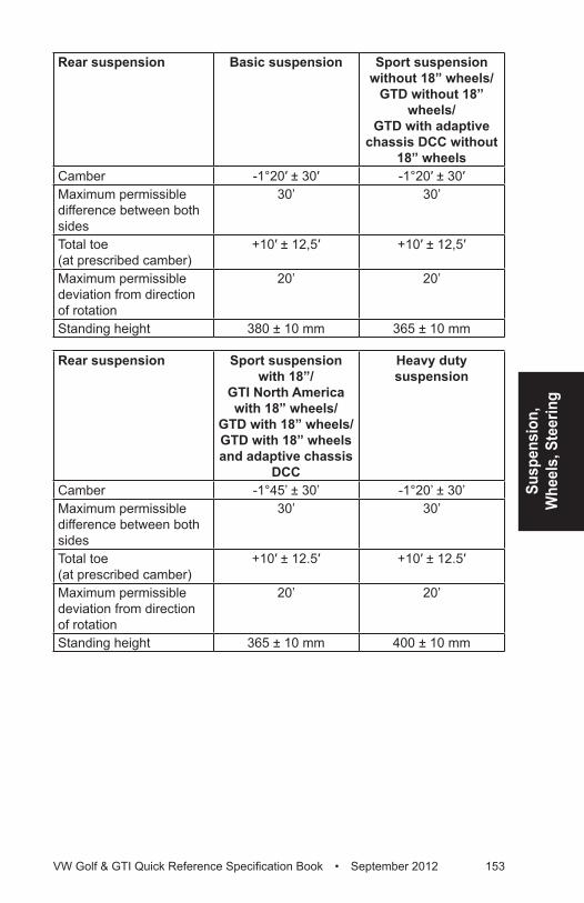
Susp
ensi
on,
Whe
els,
Ste
erin
g
VW Golf & GTI Quick Reference Specification Book • September 2012 153
Rear suspension Basic suspension Sport suspension without 18” wheels/
GTD without 18” wheels/
GTD with adaptive chassis DCC without
18” wheelsCamber -1°20′ ± 30′ -1°20′ ± 30′Maximum permissible difference between both sides
30’ 30’
Total toe (at prescribed camber)
+10′ ± 12,5′ +10′ ± 12,5′
Maximum permissible deviation from direction of rotation
20’ 20’
Standing height 380 ± 10 mm 365 ± 10 mm
Rear suspension Sport suspension with 18”/
GTI North America with 18” wheels/
GTD with 18” wheels/ GTD with 18” wheels and adaptive chassis
DCC
Heavy duty suspension
Camber -1°45’ ± 30’ -1°20’ ± 30’Maximum permissible difference between both sides
30’ 30’
Total toe (at prescribed camber)
+10′ ± 12.5′ +10′ ± 12.5′
Maximum permissible deviation from direction of rotation
20’ 20’
Standing height 365 ± 10 mm 400 ± 10 mm
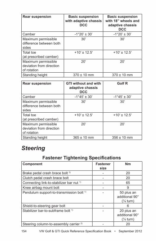
154 VW Golf & GTI Quick Reference Specification Book • September 2012
Rear suspension Basic suspension with adaptive chassis
DCC
Basic suspension with 18” wheels and
adaptive chassis DCC
Camber -1°20’ ± 30’ -1°20’ ± 30’Maximum permissible difference between both sides
30’ 30’
Total toe (at prescribed camber)
+10′ ± 12.5′ +10′ ± 12.5′
Maximum permissible deviation from direction of rotation
20’ 20’
Standing height 370 ± 10 mm 370 ± 10 mm
Rear suspension GTI without and with adaptive chassis
DCC
Golf R
Camber -1°45’ ± 30’ -1°45’ ± 30’Maximum permissible difference between both sides
30’ 30’
Total toe (at prescribed camber)
+10′ ± 12.5′ +10′ ± 12.5′
Maximum permissible deviation from direction of rotation
20’ 20’
Standing height 365 ± 10 mm 356 ± 10 mm
SteeringFastener Tightening Specifications
Component Fastener size
Nm
Brake pedal crash brace bolt 2) - 20Clutch pedal crash brace bolt - 20Connecting link-to-stabilizer bar nut 1) - 65Knee airbag mount bolt - 9Pendulum support-to-transmission bolt 1) - 50 plus an
additional 90° (¼ turn)
Shield-to-steering gear bolt - 6Stabilizer bar-to-subframe bolt 1) - 20 plus an
additional 90° (¼ turn)
Steering column-to-assembly carrier 2) - 20
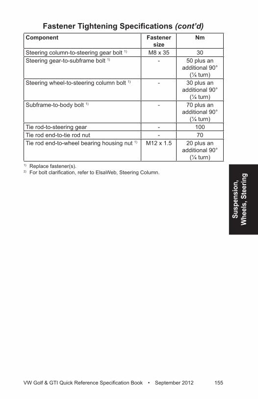
Susp
ensi
on,
Whe
els,
Ste
erin
g
VW Golf & GTI Quick Reference Specification Book • September 2012 155
Component Fastener size
Nm
Steering column-to-steering gear bolt 1) M8 x 35 30Steering gear-to-subframe bolt 1) - 50 plus an
additional 90° (¼ turn)
Steering wheel-to-steering column bolt 1) - 30 plus an additional 90°
(¼ turn)Subframe-to-body bolt 1) - 70 plus an
additional 90° (¼ turn)
Tie rod-to-steering gear - 100Tie rod end-to-tie rod nut - 70Tie rod end-to-wheel bearing housing nut 1) M12 x 1.5 20 plus an
additional 90° (¼ turn)
1) Replace fastener(s).2) For bolt clarification, refer to ElsaWeb, Steering Column.
Fastener Tightening Specifications (cont’d)
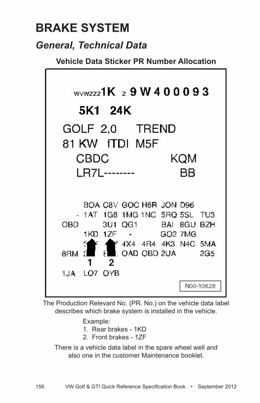
156 VW Golf & GTI Quick Reference Specification Book • September 2012
BRAKE SySTEMGeneral, Technical Data
Vehicle Data Sticker PR Number Allocation
The Production Relevant No. (PR. No.) on the vehicle data label describes which brake system is installed in the vehicle.
Example: 1. Rear brakes - 1KD 2. Front brakes - 1ZF
There is a vehicle data label in the spare wheel well and also one in the customer Maintenance booklet.
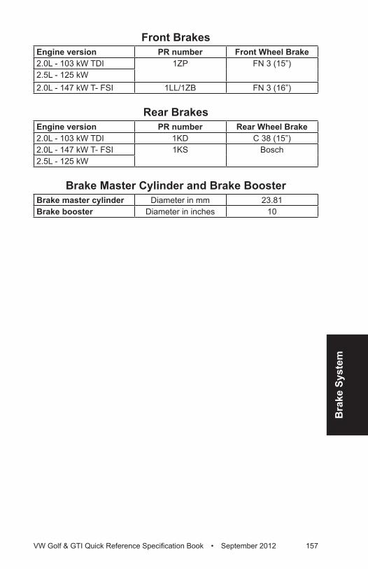
Bra
ke S
yste
m
VW Golf & GTI Quick Reference Specification Book • September 2012 157
Front BrakesEngine version PR number Front Wheel Brake2.0L - 103 kW TDI 1ZP FN 3 (15”)2.5L - 125 kW 2.0L - 147 kW T- FSI 1LL/1ZB FN 3 (16”)
Rear BrakesEngine version PR number Rear Wheel Brake2.0L - 103 kW TDI 1KD C 38 (15”)2.0L - 147 kW T- FSI 1KS Bosch2.5L - 125 kW
Brake Master Cylinder and Brake BoosterBrake master cylinder Diameter in mm 23.81Brake booster Diameter in inches 10
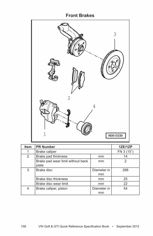
158 VW Golf & GTI Quick Reference Specification Book • September 2012
Front Brakes
Item PR Number 1ZE/1ZP1 Brake caliper FN 3 (15”)2 Brake pad thickness mm 14
Brake pad wear limit without back plate
mm 2
3 Brake disc Diameter in mm
288
Brake disc thickness mm 25Brake disc wear limit mm 22
4 Brake caliper, piston Diameter in mm
54
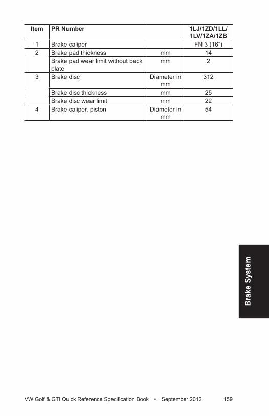
Bra
ke S
yste
m
VW Golf & GTI Quick Reference Specification Book • September 2012 159
Item PR Number 1LJ/1ZD/1LL/1LV/1ZA/1ZB
1 Brake caliper FN 3 (16”)2 Brake pad thickness mm 14
Brake pad wear limit without back plate
mm 2
3 Brake disc Diameter in mm
312
Brake disc thickness mm 25Brake disc wear limit mm 22
4 Brake caliper, piston Diameter in mm
54
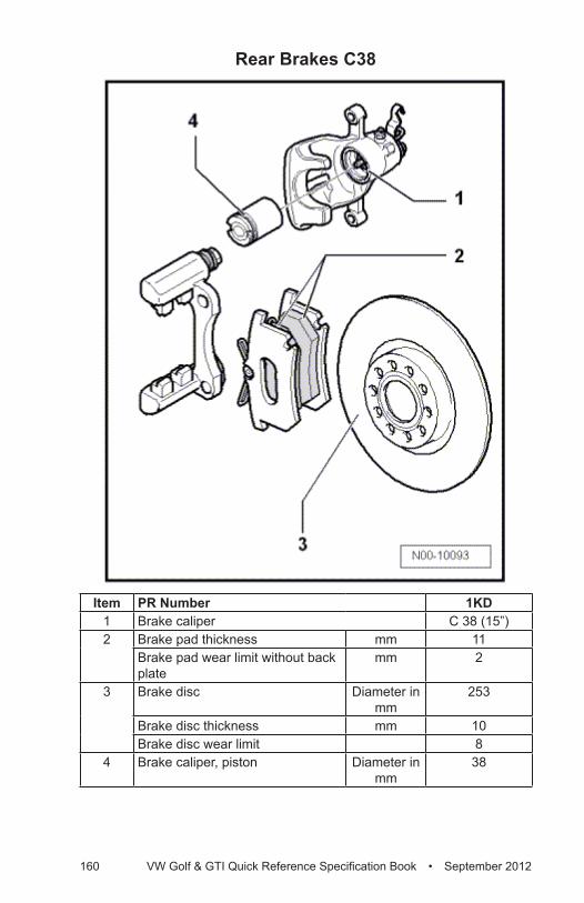
160 VW Golf & GTI Quick Reference Specification Book • September 2012
Rear Brakes C38
Item PR Number 1KD1 Brake caliper C 38 (15”)2 Brake pad thickness mm 11
Brake pad wear limit without back plate
mm 2
3 Brake disc Diameter in mm
253
Brake disc thickness mm 10Brake disc wear limit 8
4 Brake caliper, piston Diameter in mm
38
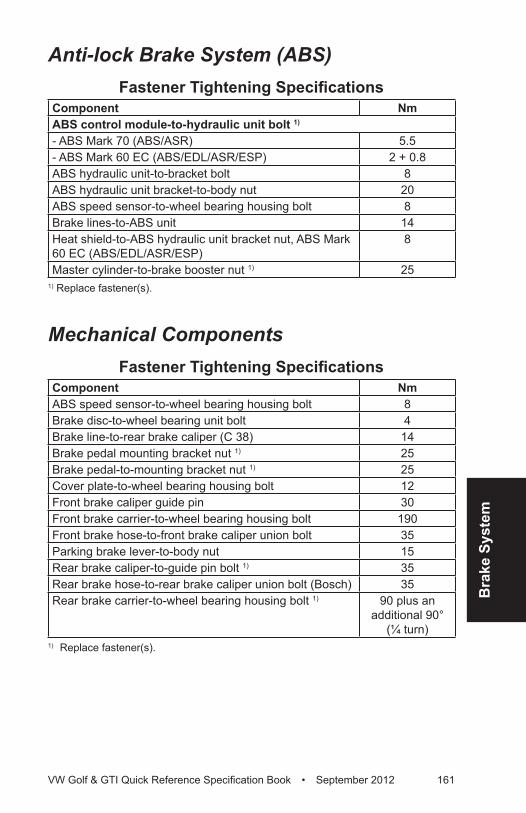
Bra
ke S
yste
m
VW Golf & GTI Quick Reference Specification Book • September 2012 161
Anti-lock Brake System (ABS)Fastener Tightening Specifications
Component NmABS control module-to-hydraulic unit bolt 1)
- ABS Mark 70 (ABS/ASR) 5.5- ABS Mark 60 EC (ABS/EDL/ASR/ESP) 2 + 0.8ABS hydraulic unit-to-bracket bolt 8ABS hydraulic unit bracket-to-body nut 20ABS speed sensor-to-wheel bearing housing bolt 8Brake lines-to-ABS unit 14Heat shield-to-ABS hydraulic unit bracket nut, ABS Mark 60 EC (ABS/EDL/ASR/ESP)
8
Master cylinder-to-brake booster nut 1) 251) Replace fastener(s).
Mechanical ComponentsFastener Tightening Specifications
Component NmABS speed sensor-to-wheel bearing housing bolt 8Brake disc-to-wheel bearing unit bolt 4Brake line-to-rear brake caliper (C 38) 14Brake pedal mounting bracket nut 1) 25Brake pedal-to-mounting bracket nut 1) 25Cover plate-to-wheel bearing housing bolt 12Front brake caliper guide pin 30Front brake carrier-to-wheel bearing housing bolt 190Front brake hose-to-front brake caliper union bolt 35Parking brake lever-to-body nut 15Rear brake caliper-to-guide pin bolt 1) 35Rear brake hose-to-rear brake caliper union bolt (Bosch) 35Rear brake carrier-to-wheel bearing housing bolt 1) 90 plus an
additional 90° (¼ turn)
1) Replace fastener(s).
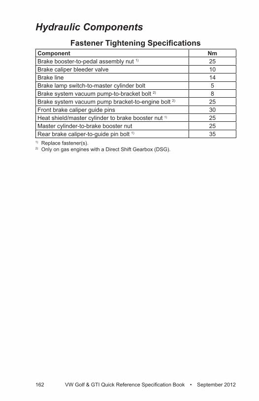
162 VW Golf & GTI Quick Reference Specification Book • September 2012
Hydraulic ComponentsFastener Tightening Specifications
Component NmBrake booster-to-pedal assembly nut 1) 25Brake caliper bleeder valve 10Brake line 14Brake lamp switch-to-master cylinder bolt 5Brake system vacuum pump-to-bracket bolt 2) 8Brake system vacuum pump bracket-to-engine bolt 2) 25Front brake caliper guide pins 30Heat shield/master cylinder to brake booster nut 1) 25Master cylinder-to-brake booster nut 25Rear brake caliper-to-guide pin bolt 1) 35
1) Replace fastener(s).2) Only on gas engines with a Direct Shift Gearbox (DSG).
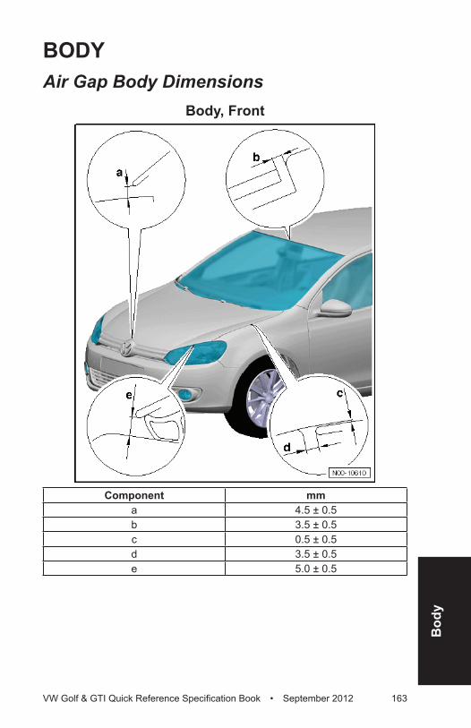
Bod
y
VW Golf & GTI Quick Reference Specification Book • September 2012 163
BODyAir Gap Body Dimensions
Body, Front
Component mma 4.5 ± 0.5 b 3.5 ± 0.5 c 0.5 ± 0.5 d 3.5 ± 0.5 e 5.0 ± 0.5
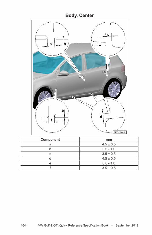
164 VW Golf & GTI Quick Reference Specification Book • September 2012
Body, Center
Component mma 4.5 ± 0.5 b 0.0 - 1.0 c 3.5 ± 0.5 d 4.5 ± 0.5 e 0.0 - 1.0f 3.5 ± 0.5
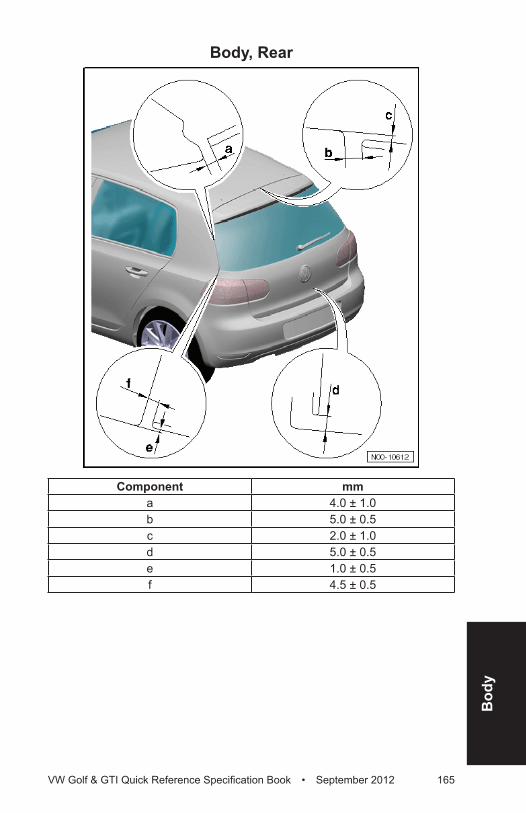
Bod
y
VW Golf & GTI Quick Reference Specification Book • September 2012 165
Body, Rear
Component mma 4.0 ± 1.0 b 5.0 ± 0.5 c 2.0 ± 1.0 d 5.0 ± 0.5 e 1.0 ± 0.5 f 4.5 ± 0.5
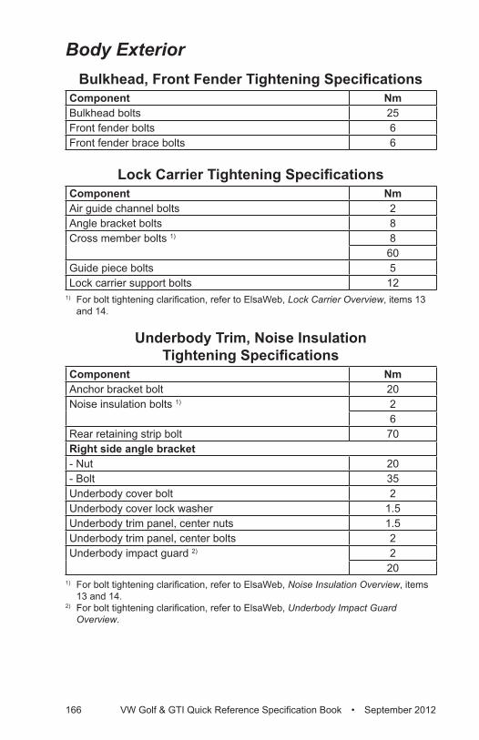
166 VW Golf & GTI Quick Reference Specification Book • September 2012
Body ExteriorBulkhead, Front Fender Tightening Specifications
Component NmBulkhead bolts 25Front fender bolts 6Front fender brace bolts 6
Lock Carrier Tightening SpecificationsComponent NmAir guide channel bolts 2Angle bracket bolts 8Cross member bolts 1) 8
60Guide piece bolts 5Lock carrier support bolts 12
1) For bolt tightening clarification, refer to ElsaWeb, Lock Carrier Overview, items 13 and 14.
Underbody Trim, Noise Insulation Tightening Specifications
Component NmAnchor bracket bolt 20Noise insulation bolts 1) 2
6Rear retaining strip bolt 70Right side angle bracket- Nut 20- Bolt 35Underbody cover bolt 2Underbody cover lock washer 1.5Underbody trim panel, center nuts 1.5Underbody trim panel, center bolts 2Underbody impact guard 2) 2
201) For bolt tightening clarification, refer to ElsaWeb, Noise Insulation Overview, items
13 and 14.2) For bolt tightening clarification, refer to ElsaWeb, Underbody Impact Guard
Overview.
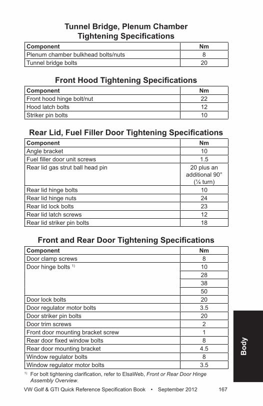
Bod
y
VW Golf & GTI Quick Reference Specification Book • September 2012 167
Tunnel Bridge, Plenum Chamber Tightening Specifications
Component NmPlenum chamber bulkhead bolts/nuts 8Tunnel bridge bolts 20
Front Hood Tightening SpecificationsComponent NmFront hood hinge bolt/nut 22Hood latch bolts 12Striker pin bolts 10
Rear Lid, Fuel Filler Door Tightening SpecificationsComponent NmAngle bracket 10Fuel filler door unit screws 1.5Rear lid gas strut ball head pin 20 plus an
additional 90° (¼ turn)
Rear lid hinge bolts 10Rear lid hinge nuts 24Rear lid lock bolts 23Rear lid latch screws 12Rear lid striker pin bolts 18
Front and Rear Door Tightening SpecificationsComponent NmDoor clamp screws 8Door hinge bolts 1) 10
28 3850
Door lock bolts 20Door regulator motor bolts 3.5Door striker pin bolts 20Door trim screws 2Front door mounting bracket screw 1Rear door fixed window bolts 8Rear door mounting bracket 4.5Window regulator bolts 8Window regulator motor bolts 3.5
1) For bolt tightening clarification, refer to ElsaWeb, Front or Rear Door Hinge Assembly Overview.
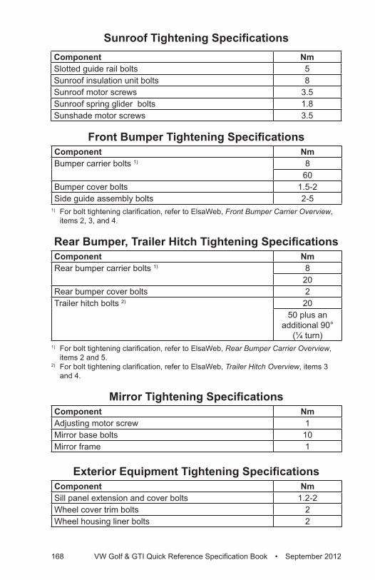
168 VW Golf & GTI Quick Reference Specification Book • September 2012
Sunroof Tightening SpecificationsComponent NmSlotted guide rail bolts 5Sunroof insulation unit bolts 8Sunroof motor screws 3.5Sunroof spring glider bolts 1.8Sunshade motor screws 3.5
Front Bumper Tightening SpecificationsComponent NmBumper carrier bolts 1) 8
60Bumper cover bolts 1.5-2Side guide assembly bolts 2-5
1) For bolt tightening clarification, refer to ElsaWeb, Front Bumper Carrier Overview, items 2, 3, and 4.
Rear Bumper, Trailer Hitch Tightening SpecificationsComponent NmRear bumper carrier bolts 1) 8
20Rear bumper cover bolts 2Trailer hitch bolts 2) 20
50 plus an additional 90°
(¼ turn)1) For bolt tightening clarification, refer to ElsaWeb, Rear Bumper Carrier Overview,
items 2 and 5.2) For bolt tightening clarification, refer to ElsaWeb, Trailer Hitch Overview, items 3
and 4.
Mirror Tightening SpecificationsComponent NmAdjusting motor screw 1Mirror base bolts 10Mirror frame 1
Exterior Equipment Tightening SpecificationsComponent NmSill panel extension and cover bolts 1.2-2Wheel cover trim bolts 2Wheel housing liner bolts 2
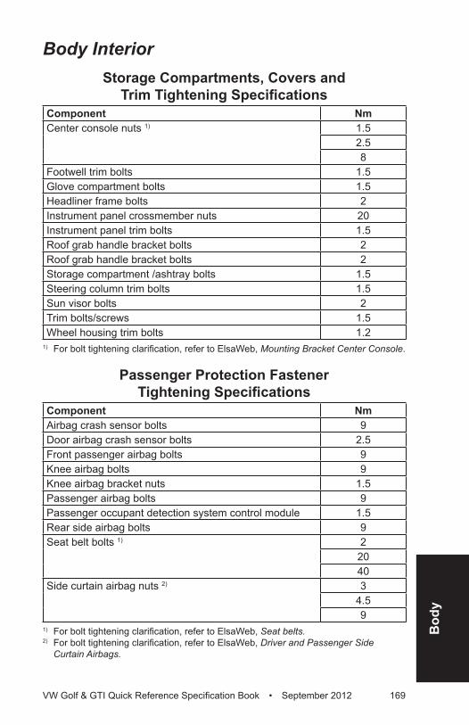
Bod
y
VW Golf & GTI Quick Reference Specification Book • September 2012 169
Body InteriorStorage Compartments, Covers and
Trim Tightening SpecificationsComponent NmCenter console nuts 1) 1.5
2.58
Footwell trim bolts 1.5Glove compartment bolts 1.5Headliner frame bolts 2Instrument panel crossmember nuts 20Instrument panel trim bolts 1.5Roof grab handle bracket bolts 2Roof grab handle bracket bolts 2Storage compartment /ashtray bolts 1.5Steering column trim bolts 1.5Sun visor bolts 2Trim bolts/screws 1.5Wheel housing trim bolts 1.2
1) For bolt tightening clarification, refer to ElsaWeb, Mounting Bracket Center Console.
Passenger Protection Fastener Tightening Specifications
Component NmAirbag crash sensor bolts 9Door airbag crash sensor bolts 2.5Front passenger airbag bolts 9Knee airbag bolts 9Knee airbag bracket nuts 1.5Passenger airbag bolts 9Passenger occupant detection system control module 1.5Rear side airbag bolts 9Seat belt bolts 1) 2
2040
Side curtain airbag nuts 2) 3 4.59
1) For bolt tightening clarification, refer to ElsaWeb, Seat belts.2) For bolt tightening clarification, refer to ElsaWeb, Driver and Passenger Side
Curtain Airbags.
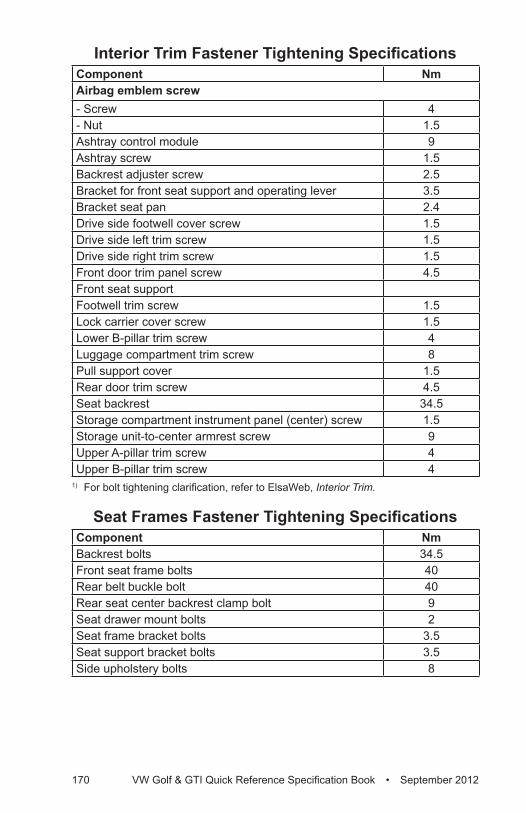
170 VW Golf & GTI Quick Reference Specification Book • September 2012
Interior Trim Fastener Tightening SpecificationsComponent NmAirbag emblem screw- Screw 4- Nut 1.5Ashtray control module 9Ashtray screw 1.5Backrest adjuster screw 2.5Bracket for front seat support and operating lever 3.5Bracket seat pan 2.4Drive side footwell cover screw 1.5Drive side left trim screw 1.5Drive side right trim screw 1.5Front door trim panel screw 4.5Front seat supportFootwell trim screw 1.5Lock carrier cover screw 1.5Lower B-pillar trim screw 4Luggage compartment trim screw 8Pull support cover 1.5Rear door trim screw 4.5Seat backrest 34.5Storage compartment instrument panel (center) screw 1.5Storage unit-to-center armrest screw 9Upper A-pillar trim screw 4Upper B-pillar trim screw 4
1) For bolt tightening clarification, refer to ElsaWeb, Interior Trim.
Seat Frames Fastener Tightening SpecificationsComponent NmBackrest bolts 34.5Front seat frame bolts 40Rear belt buckle bolt 40Rear seat center backrest clamp bolt 9Seat drawer mount bolts 2Seat frame bracket bolts 3.5Seat support bracket bolts 3.5Side upholstery bolts 8

Heat
ing
&
Air C
ondi
tioni
ng
VW Golf & GTI Quick Reference Specification Book • September 2012 171
HEATING, VENTILATION AND AIR CONDITIONINGGeneral, Technical Data
Refrigerant Oil DistributionComponent Approximate % of total amount
of oil in componentA/C compressor 50Condenser 10Suction hose 10Evaporator 20Fluid reservoir 10
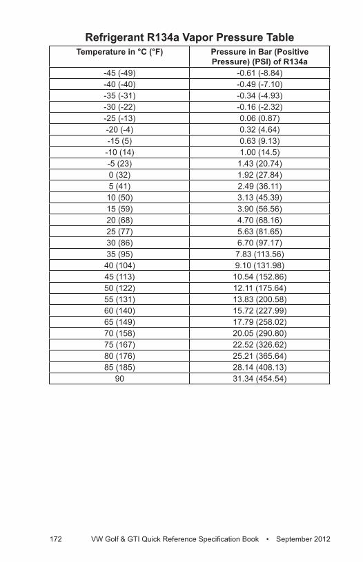
172 VW Golf & GTI Quick Reference Specification Book • September 2012
Refrigerant R134a Vapor Pressure TableTemperature in °C (°F) Pressure in Bar (Positive
Pressure) (PSI) of R134a-45 (-49) -0.61 (-8.84)-40 (-40) -0.49 (-7.10)-35 (-31) -0.34 (-4.93)-30 (-22) -0.16 (-2.32)-25 (-13) 0.06 (0.87)-20 (-4) 0.32 (4.64)-15 (5) 0.63 (9.13)-10 (14) 1.00 (14.5)-5 (23) 1.43 (20.74)0 (32) 1.92 (27.84)5 (41) 2.49 (36.11)
10 (50) 3.13 (45.39)15 (59) 3.90 (56.56)20 (68) 4.70 (68.16)25 (77) 5.63 (81.65)30 (86) 6.70 (97.17)35 (95) 7.83 (113.56)
40 (104) 9.10 (131.98)45 (113) 10.54 (152.86)50 (122) 12.11 (175.64)55 (131) 13.83 (200.58)60 (140) 15.72 (227.99)65 (149) 17.79 (258.02)70 (158) 20.05 (290.80)75 (167) 22.52 (326.62)80 (176) 25.21 (365.64)85 (185) 28.14 (408.13)
90 31.34 (454.54)
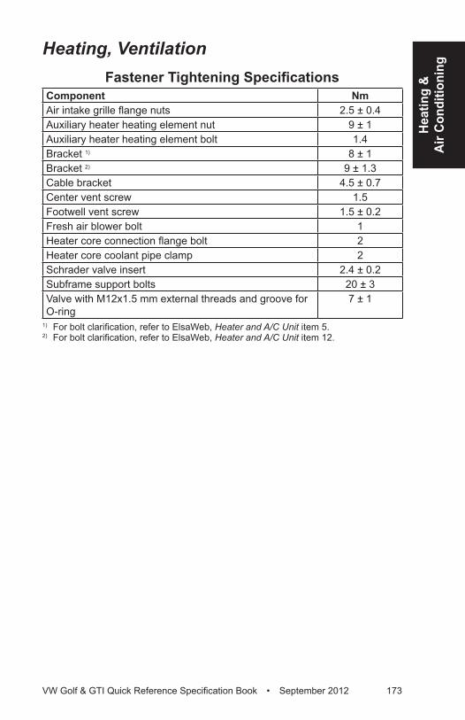
Heat
ing
&
Air C
ondi
tioni
ng
VW Golf & GTI Quick Reference Specification Book • September 2012 173
Heating, VentilationFastener Tightening Specifications
Component NmAir intake grille flange nuts 2.5 ± 0.4Auxiliary heater heating element nut 9 ± 1Auxiliary heater heating element bolt 1.4Bracket 1) 8 ± 1Bracket 2) 9 ± 1.3Cable bracket 4.5 ± 0.7Center vent screw 1.5Footwell vent screw 1.5 ± 0.2Fresh air blower bolt 1Heater core connection flange bolt 2Heater core coolant pipe clamp 2Schrader valve insert 2.4 ± 0.2Subframe support bolts 20 ± 3Valve with M12x1.5 mm external threads and groove for O-ring
7 ± 1
1) For bolt clarification, refer to ElsaWeb, Heater and A/C Unit item 5.2) For bolt clarification, refer to ElsaWeb, Heater and A/C Unit item 12.
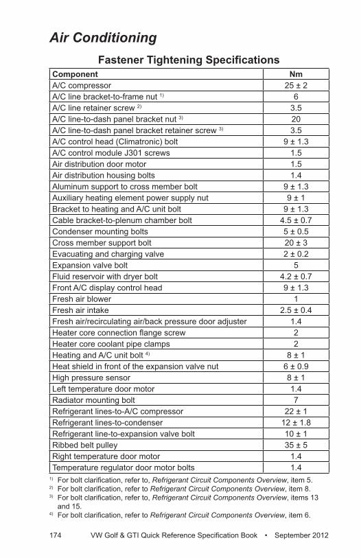
174 VW Golf & GTI Quick Reference Specification Book • September 2012
Air ConditioningFastener Tightening Specifications
Component NmA/C compressor 25 ± 2A/C line bracket-to-frame nut 1) 6A/C line retainer screw 2) 3.5A/C line-to-dash panel bracket nut 3) 20A/C line-to-dash panel bracket retainer screw 3) 3.5A/C control head (Climatronic) bolt 9 ± 1.3A/C control module J301 screws 1.5Air distribution door motor 1.5Air distribution housing bolts 1.4Aluminum support to cross member bolt 9 ± 1.3Auxiliary heating element power supply nut 9 ± 1Bracket to heating and A/C unit bolt 9 ± 1.3Cable bracket-to-plenum chamber bolt 4.5 ± 0.7Condenser mounting bolts 5 ± 0.5Cross member support bolt 20 ± 3Evacuating and charging valve 2 ± 0.2Expansion valve bolt 5Fluid reservoir with dryer bolt 4.2 ± 0.7Front A/C display control head 9 ± 1.3Fresh air blower 1Fresh air intake 2.5 ± 0.4Fresh air/recirculating air/back pressure door adjuster 1.4Heater core connection flange screw 2Heater core coolant pipe clamps 2Heating and A/C unit bolt 4) 8 ± 1Heat shield in front of the expansion valve nut 6 ± 0.9High pressure sensor 8 ± 1Left temperature door motor 1.4Radiator mounting bolt 7Refrigerant lines-to-A/C compressor 22 ± 1Refrigerant lines-to-condenser 12 ± 1.8Refrigerant line-to-expansion valve bolt 10 ± 1Ribbed belt pulley 35 ± 5Right temperature door motor 1.4Temperature regulator door motor bolts 1.4
1) For bolt clarification, refer to, Refrigerant Circuit Components Overview, item 5.2) For bolt clarification, refer to Refrigerant Circuit Components Overview, item 8.3) For bolt clarification, refer to, Refrigerant Circuit Components Overview, items 13
and 15.4) For bolt clarification, refer to Refrigerant Circuit Components Overview, item 6.
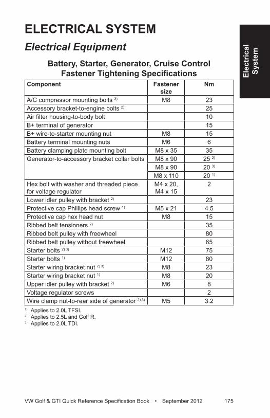
Elec
tric
alSy
stem
VW Golf & GTI Quick Reference Specification Book • September 2012 175
ELECTRICAL SySTEMElectrical Equipment
Battery, Starter, Generator, Cruise Control Fastener Tightening Specifications
Component Fastener size
Nm
A/C compressor mounting bolts 3) M8 23Accessory bracket-to-engine bolts 2) 25Air filter housing-to-body bolt 10B+ terminal of generator 15B+ wire-to-starter mounting nut M8 15Battery terminal mounting nuts M6 6Battery clamping plate mounting bolt M8 x 35 35Generator-to-accessory bracket collar bolts M8 x 90 25 2)
M8 x 90 20 3)
M8 x 110 20 1)
Hex bolt with washer and threaded piece for voltage regulator
M4 x 20, M4 x 15
2
Lower idler pulley with bracket 2) 23Protective cap Phillips head screw 1) M5 x 21 4.5Protective cap hex head nut M8 15Ribbed belt tensioners 2) 35Ribbed belt pulley with freewheel 80Ribbed belt pulley without freewheel 65Starter bolts 2) 3) M12 75Starter bolts 1) M12 80Starter wiring bracket nut 2) 3) M8 23Starter wiring bracket nut 1) M8 20Upper idler pulley with bracket 2) M6 8Voltage regulator screws 2Wire clamp nut-to-rear side of generator 2) 3) M5 3.2
1) Applies to 2.0L TFSI.2) Applies to 2.5L and Golf R.3) Applies to 2.0L TDI.
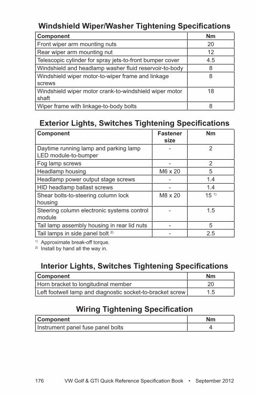
176 VW Golf & GTI Quick Reference Specification Book • September 2012
Windshield Wiper/Washer Tightening SpecificationsComponent NmFront wiper arm mounting nuts 20Rear wiper arm mounting nut 12Telescopic cylinder for spray jets-to-front bumper cover 4.5Windshield and headlamp washer fluid reservoir-to-body 8Windshield wiper motor-to-wiper frame and linkage screws
8
Windshield wiper motor crank-to-windshield wiper motor shaft
18
Wiper frame with linkage-to-body bolts 8
Exterior Lights, Switches Tightening SpecificationsComponent Fastener
sizeNm
Daytime running lamp and parking lamp LED module-to-bumper
- 2
Fog lamp screws - 2Headlamp housing M6 x 20 5Headlamp power output stage screws - 1.4HID headlamp ballast screws - 1.4Shear bolts-to-steering column lock housing
M8 x 20 15 1)
Steering column electronic systems control module
- 1.5
Tail lamp assembly housing in rear lid nuts - 5Tail lamps in side panel bolt 2) - 2.5
1) Approximate break-off torque.2) Install by hand all the way in.
Interior Lights, Switches Tightening SpecificationsComponent NmHorn bracket to longitudinal member 20Left footwell lamp and diagnostic socket-to-bracket screw 1.5
Wiring Tightening SpecificationComponent NmInstrument panel fuse panel bolts 4
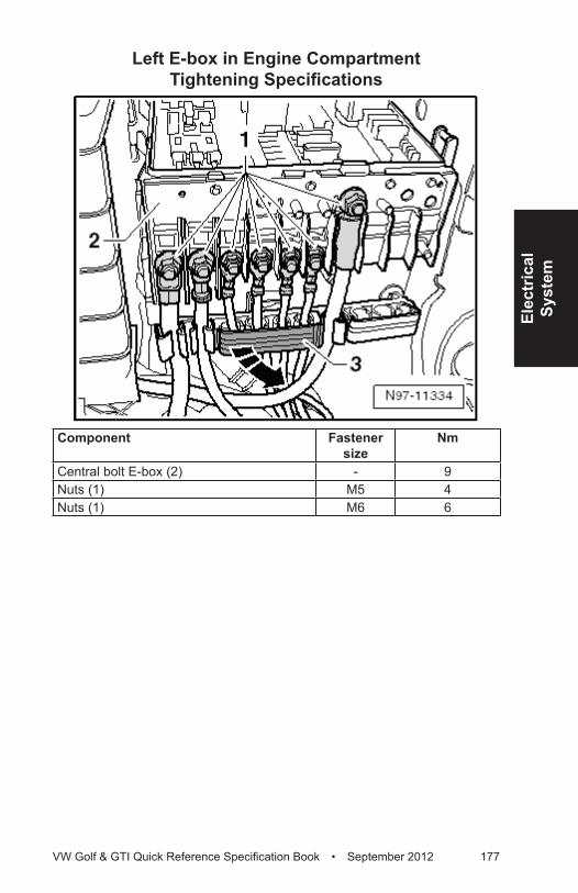
Elec
tric
alSy
stem
VW Golf & GTI Quick Reference Specification Book • September 2012 177
Left E-box in Engine Compartment Tightening Specifications
Component Fastener size
Nm
Central bolt E-box (2) - 9Nuts (1) M5 4Nuts (1) M6 6
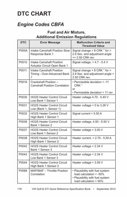
178 VW Golf & GTI Quick Reference Specification Book • September 2012
DTC CHART
Engine Codes CBFAFuel and Air Mixture,
Additional Emission RegulationsDTC Error Message Malfunction Criteria and
Threshold ValueP000A Intake Camshaft Position Slow
Response Bank 1Signal change > 8 CRK ° for > 2.9 Sec. and adjustment angle >= 2.50 CRK rev.
P0010 Intake Camshaft Position Actuator Circuit Open Bank 1
Signal voltage, > 4.7 - 5.4 V
P0011 Intake Camshaft Position Timing - Over-Advanced Bank 1
Signal change > 8 CRK ° for > 2.9 Sec. and adjustment angle < 2.50 CRK rev.
P0016 Crankshaft Position – Camshaft Position Correlation
• Permissible deviation < -11 CRK °
or• Permissible deviation > 11 rev
P0030 HO2S Heater Control Circuit Low Bank 1 Sensor 1
Heater voltage 4.70 - 5.40 V
P0031 HO2S Heater Control Circuit Low (Bank 1, Sensor 1)
Heater voltage < 0 to 3.26 V
P0032 HO2S Heater Control Circuit High Bank 1 Sensor 1
Signal current > 5.50 A
P0036 HO2S Heater Control Circuit Bank 1 Sensor 2
Heater voltage, 4.50 - 5.50 V
P0037 HO2S Heater Control Circuit Low Bank 1 Sensor 2
Heater voltage < 3.00 V
P0038 HO2S Heater Control Circuit High Bank 1 Sensor 2
Heater current, > 2.70 - 5.50 A
P0042 HO2S Heater Control Circuit Bank 1 Sensor 3
Heater voltage < 2.34 V
P0043 HO2S Heater Control Circuit Low Bank 1 Sensor 3
Heater voltage < 2.34 V
P0044 HO2S Heater Control Circuit High Bank 1 Sensor 3
Heater voltage > 3.59 V
P0068 MAP/MAF – Throttle Position Correlation
• Plausibility with fuel system load calculation < -50%
• Plausibility with fuel system load calculation > 50%
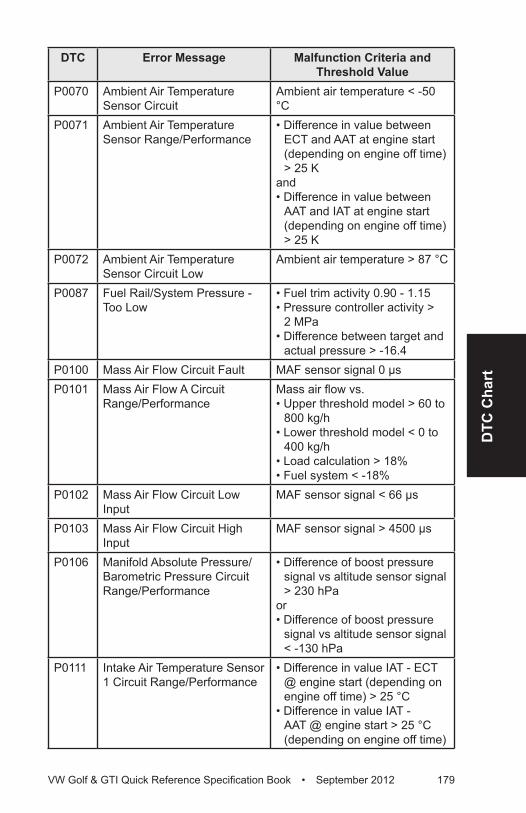
DTC
Cha
rt
VW Golf & GTI Quick Reference Specification Book • September 2012 179
DTC Error Message Malfunction Criteria and Threshold Value
P0070 Ambient Air Temperature Sensor Circuit
Ambient air temperature < -50 °C
P0071 Ambient Air Temperature Sensor Range/Performance
• Difference in value between ECT and AAT at engine start (depending on engine off time) > 25 K
and• Difference in value between
AAT and IAT at engine start (depending on engine off time) > 25 K
P0072 Ambient Air Temperature Sensor Circuit Low
Ambient air temperature > 87 °C
P0087 Fuel Rail/System Pressure - Too Low
• Fuel trim activity 0.90 - 1.15• Pressure controller activity >
2 MPa• Difference between target and
actual pressure > -16.4P0100 Mass Air Flow Circuit Fault MAF sensor signal 0 µsP0101 Mass Air Flow A Circuit
Range/PerformanceMass air flow vs.• Upper threshold model > 60 to
800 kg/h• Lower threshold model < 0 to
400 kg/h• Load calculation > 18%• Fuel system < -18%
P0102 Mass Air Flow Circuit Low Input
MAF sensor signal < 66 µs
P0103 Mass Air Flow Circuit High Input
MAF sensor signal > 4500 µs
P0106 Manifold Absolute Pressure/Barometric Pressure Circuit Range/Performance
• Difference of boost pressure signal vs altitude sensor signal > 230 hPa
or• Difference of boost pressure
signal vs altitude sensor signal < -130 hPa
P0111 Intake Air Temperature Sensor 1 Circuit Range/Performance
• Difference in value IAT - ECT @ engine start (depending on engine off time) > 25 °C
• Difference in value IAT - AAT @ engine start > 25 °C (depending on engine off time)
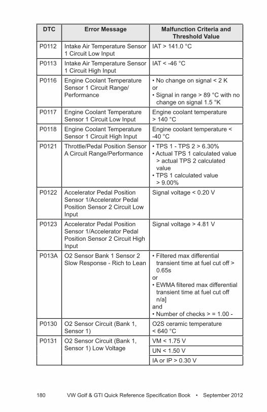
180 VW Golf & GTI Quick Reference Specification Book • September 2012
DTC Error Message Malfunction Criteria and Threshold Value
P0112 Intake Air Temperature Sensor 1 Circuit Low Input
IAT > 141.0 °C
P0113 Intake Air Temperature Sensor 1 Circuit High Input
IAT < -46 °C
P0116 Engine Coolant Temperature Sensor 1 Circuit Range/Performance
• No change on signal < 2 Kor• Signal in range > 89 °C with no
change on signal 1.5 °K P0117 Engine Coolant Temperature
Sensor 1 Circuit Low InputEngine coolant temperature > 140 °C
P0118 Engine Coolant Temperature Sensor 1 Circuit High Input
Engine coolant temperature < -40 °C
P0121 Throttle/Pedal Position Sensor A Circuit Range/Performance
• TPS 1 - TPS 2 > 6.30%• Actual TPS 1 calculated value
> actual TPS 2 calculated value
• TPS 1 calculated value > 9.00%
P0122 Accelerator Pedal Position Sensor 1/Accelerator Pedal Position Sensor 2 Circuit Low Input
Signal voltage < 0.20 V
P0123 Accelerator Pedal Position Sensor 1/Accelerator Pedal Position Sensor 2 Circuit High Input
Signal voltage > 4.81 V
P013A O2 Sensor Bank 1 Sensor 2 Slow Response - Rich to Lean
• Filtered max differential transient time at fuel cut off > 0.65s
or• EWMA filtered max differential
transient time at fuel cut off n/a]
and• Number of checks > = 1.00 -
P0130 O2 Sensor Circuit (Bank 1, Sensor 1)
O2S ceramic temperature < 640 °C
P0131 O2 Sensor Circuit (Bank 1, Sensor 1) Low Voltage
VM < 1.75 VUN < 1.50 VIA or IP > 0.30 V
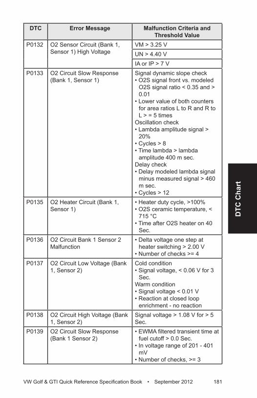
DTC
Cha
rt
VW Golf & GTI Quick Reference Specification Book • September 2012 181
DTC Error Message Malfunction Criteria and Threshold Value
P0132 O2 Sensor Circuit (Bank 1, Sensor 1) High Voltage
VM > 3.25 VUN > 4.40 VIA or IP > 7 V
P0133 O2 Circuit Slow Response (Bank 1, Sensor 1)
Signal dynamic slope check• O2S signal front vs. modeled
O2S signal ratio < 0.35 and > 0.01
• Lower value of both counters for area ratios L to R and R to L > = 5 times
Oscillation check • Lambda amplitude signal >
20%• Cycles > 8• Time lambda > lambda
amplitude 400 m sec.Delay check • Delay modeled lambda signal
minus measured signal > 460 m sec.
• Cycles > 12P0135 O2 Heater Circuit (Bank 1,
Sensor 1)• Heater duty cycle, >100%• O2S ceramic temperature, <
715 °C• Time after O2S heater on 40
Sec.P0136 O2 Circuit Bank 1 Sensor 2
Malfunction• Delta voltage one step at
heater switching > 2.00 V• Number of checks >= 4
P0137 O2 Circuit Low Voltage (Bank 1, Sensor 2)
Cold condition• Signal voltage, < 0.06 V for 3
Sec.Warm condition• Signal voltage < 0.01 V • Reaction at closed loop
enrichment - no reactionP0138 O2 Circuit High Voltage (Bank
1, Sensor 2)Signal voltage > 1.08 V for > 5 Sec.
P0139 O2 Circuit Slow Response (Bank 1 Sensor 2)
• EWMA filtered transient time at fuel cutoff > 0.0 Sec.
• In voltage range of 201 - 401 mV
• Number of checks, >= 3
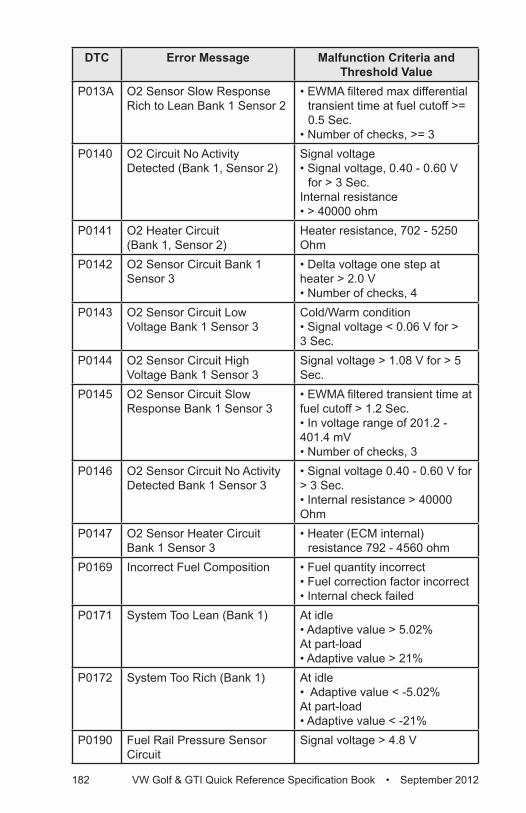
182 VW Golf & GTI Quick Reference Specification Book • September 2012
DTC Error Message Malfunction Criteria and Threshold Value
P013A O2 Sensor Slow Response Rich to Lean Bank 1 Sensor 2
• EWMA filtered max differential transient time at fuel cutoff >= 0.5 Sec.
• Number of checks, >= 3P0140 O2 Circuit No Activity
Detected (Bank 1, Sensor 2)Signal voltage• Signal voltage, 0.40 - 0.60 V
for > 3 Sec.Internal resistance• > 40000 ohm
P0141 O2 Heater Circuit (Bank 1, Sensor 2)
Heater resistance, 702 - 5250 Ohm
P0142 O2 Sensor Circuit Bank 1 Sensor 3
• Delta voltage one step at heater > 2.0 V• Number of checks, 4
P0143 O2 Sensor Circuit Low Voltage Bank 1 Sensor 3
Cold/Warm condition• Signal voltage < 0.06 V for > 3 Sec.
P0144 O2 Sensor Circuit High Voltage Bank 1 Sensor 3
Signal voltage > 1.08 V for > 5 Sec.
P0145 O2 Sensor Circuit Slow Response Bank 1 Sensor 3
• EWMA filtered transient time at fuel cutoff > 1.2 Sec.• In voltage range of 201.2 - 401.4 mV• Number of checks, 3
P0146 O2 Sensor Circuit No Activity Detected Bank 1 Sensor 3
• Signal voltage 0.40 - 0.60 V for > 3 Sec.• Internal resistance > 40000 Ohm
P0147 O2 Sensor Heater Circuit Bank 1 Sensor 3
• Heater (ECM internal) resistance 792 - 4560 ohm
P0169 Incorrect Fuel Composition • Fuel quantity incorrect• Fuel correction factor incorrect• Internal check failed
P0171 System Too Lean (Bank 1) At idle • Adaptive value > 5.02%At part-load • Adaptive value > 21%
P0172 System Too Rich (Bank 1) At idle • Adaptive value < -5.02%At part-load• Adaptive value < -21%
P0190 Fuel Rail Pressure Sensor Circuit
Signal voltage > 4.8 V
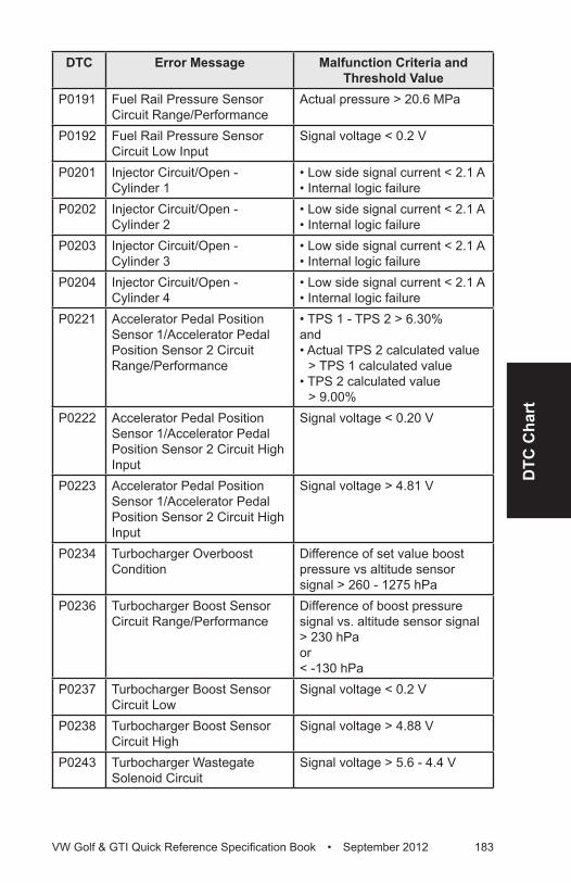
DTC
Cha
rt
VW Golf & GTI Quick Reference Specification Book • September 2012 183
DTC Error Message Malfunction Criteria and Threshold Value
P0191 Fuel Rail Pressure Sensor Circuit Range/Performance
Actual pressure > 20.6 MPa
P0192 Fuel Rail Pressure Sensor Circuit Low Input
Signal voltage < 0.2 V
P0201 Injector Circuit/Open - Cylinder 1
• Low side signal current < 2.1 A• Internal logic failure
P0202 Injector Circuit/Open - Cylinder 2
• Low side signal current < 2.1 A• Internal logic failure
P0203 Injector Circuit/Open - Cylinder 3
• Low side signal current < 2.1 A• Internal logic failure
P0204 Injector Circuit/Open - Cylinder 4
• Low side signal current < 2.1 A• Internal logic failure
P0221 Accelerator Pedal Position Sensor 1/Accelerator Pedal Position Sensor 2 Circuit Range/Performance
• TPS 1 - TPS 2 > 6.30%and• Actual TPS 2 calculated value
> TPS 1 calculated value• TPS 2 calculated value
> 9.00%P0222 Accelerator Pedal Position
Sensor 1/Accelerator Pedal Position Sensor 2 Circuit High Input
Signal voltage < 0.20 V
P0223 Accelerator Pedal Position Sensor 1/Accelerator Pedal Position Sensor 2 Circuit High Input
Signal voltage > 4.81 V
P0234 Turbocharger Overboost Condition
Difference of set value boost pressure vs altitude sensor signal > 260 - 1275 hPa
P0236 Turbocharger Boost Sensor Circuit Range/Performance
Difference of boost pressure signal vs. altitude sensor signal > 230 hPa or < -130 hPa
P0237 Turbocharger Boost Sensor Circuit Low
Signal voltage < 0.2 V
P0238 Turbocharger Boost Sensor Circuit High
Signal voltage > 4.88 V
P0243 Turbocharger Wastegate Solenoid Circuit
Signal voltage > 5.6 - 4.4 V
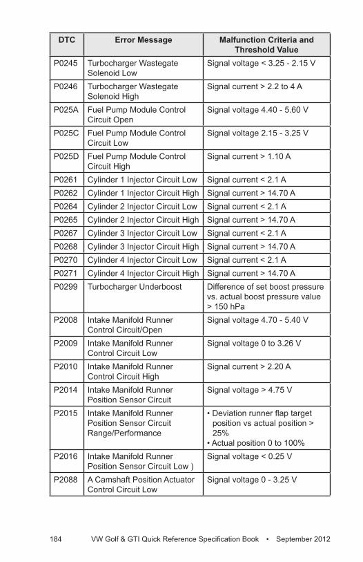
184 VW Golf & GTI Quick Reference Specification Book • September 2012
DTC Error Message Malfunction Criteria and Threshold Value
P0245 Turbocharger Wastegate Solenoid Low
Signal voltage < 3.25 - 2.15 V
P0246 Turbocharger Wastegate Solenoid High
Signal current > 2.2 to 4 A
P025A Fuel Pump Module Control Circuit Open
Signal voltage 4.40 - 5.60 V
P025C Fuel Pump Module Control Circuit Low
Signal voltage 2.15 - 3.25 V
P025D Fuel Pump Module Control Circuit High
Signal current > 1.10 A
P0261 Cylinder 1 Injector Circuit Low Signal current < 2.1 AP0262 Cylinder 1 Injector Circuit High Signal current > 14.70 AP0264 Cylinder 2 Injector Circuit Low Signal current < 2.1 AP0265 Cylinder 2 Injector Circuit High Signal current > 14.70 AP0267 Cylinder 3 Injector Circuit Low Signal current < 2.1 AP0268 Cylinder 3 Injector Circuit High Signal current > 14.70 AP0270 Cylinder 4 Injector Circuit Low Signal current < 2.1 AP0271 Cylinder 4 Injector Circuit High Signal current > 14.70 AP0299 Turbocharger Underboost Difference of set boost pressure
vs. actual boost pressure value > 150 hPa
P2008 Intake Manifold Runner Control Circuit/Open
Signal voltage 4.70 - 5.40 V
P2009 Intake Manifold Runner Control Circuit Low
Signal voltage 0 to 3.26 V
P2010 Intake Manifold Runner Control Circuit High
Signal current > 2.20 A
P2014 Intake Manifold Runner Position Sensor Circuit
Signal voltage > 4.75 V
P2015 Intake Manifold Runner Position Sensor Circuit Range/Performance
• Deviation runner flap target position vs actual position > 25%
• Actual position 0 to 100%P2016 Intake Manifold Runner
Position Sensor Circuit Low )Signal voltage < 0.25 V
P2088 A Camshaft Position Actuator Control Circuit Low
Signal voltage 0 - 3.25 V
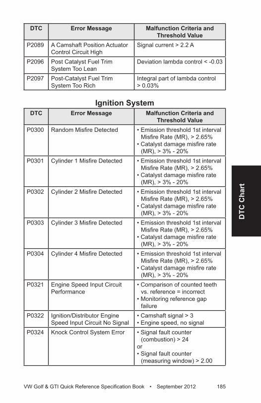
DTC
Cha
rt
VW Golf & GTI Quick Reference Specification Book • September 2012 185
DTC Error Message Malfunction Criteria and Threshold Value
P2089 A Camshaft Position Actuator Control Circuit High
Signal current > 2.2 A
P2096 Post Catalyst Fuel Trim System Too Lean
Deviation lambda control < -0.03
P2097 Post-Catalyst Fuel Trim System Too Rich
Integral part of lambda control > 0.03%
Ignition SystemDTC Error Message Malfunction Criteria and
Threshold ValueP0300 Random Misfire Detected • Emission threshold 1st interval
Misfire Rate (MR), > 2.65%• Catalyst damage misfire rate
(MR), > 3% - 20%P0301 Cylinder 1 Misfire Detected • Emission threshold 1st interval
Misfire Rate (MR), > 2.65%• Catalyst damage misfire rate
(MR), > 3% - 20% P0302 Cylinder 2 Misfire Detected • Emission threshold 1st interval
Misfire Rate (MR), > 2.65% • Catalyst damage misfire rate
(MR), > 3% - 20% P0303 Cylinder 3 Misfire Detected • Emission threshold 1st interval
Misfire Rate (MR), > 2.65% • Catalyst damage misfire rate
(MR), > 3% - 20% P0304 Cylinder 4 Misfire Detected • Emission threshold 1st interval
Misfire Rate (MR), > 2.65% • Catalyst damage misfire rate
(MR), > 3% - 20%P0321 Engine Speed Input Circuit
Performance• Comparison of counted teeth
vs. reference = incorrect• Monitoring reference gap
failureP0322 Ignition/Distributor Engine
Speed Input Circuit No Signal• Camshaft signal > 3• Engine speed, no signal
P0324 Knock Control System Error • Signal fault counter (combustion) > 24
or • Signal fault counter
(measuring window) > 2.00
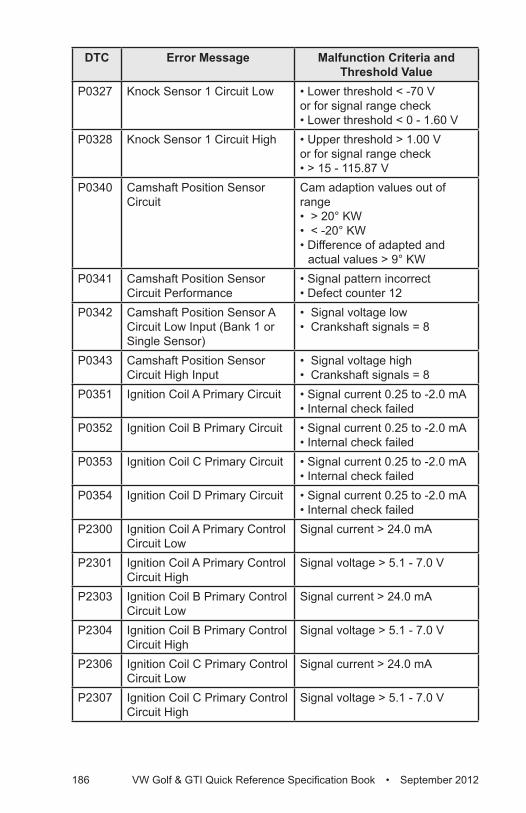
186 VW Golf & GTI Quick Reference Specification Book • September 2012
DTC Error Message Malfunction Criteria and Threshold Value
P0327 Knock Sensor 1 Circuit Low • Lower threshold < -70 V or for signal range check• Lower threshold < 0 - 1.60 V
P0328 Knock Sensor 1 Circuit High • Upper threshold > 1.00 Vor for signal range check • > 15 - 115.87 V
P0340 Camshaft Position Sensor Circuit
Cam adaption values out of range • > 20° KW• < -20° KW• Difference of adapted and
actual values > 9° KWP0341 Camshaft Position Sensor
Circuit Performance• Signal pattern incorrect• Defect counter 12
P0342 Camshaft Position Sensor A Circuit Low Input (Bank 1 or Single Sensor)
• Signal voltage low• Crankshaft signals = 8
P0343 Camshaft Position Sensor Circuit High Input
• Signal voltage high• Crankshaft signals = 8
P0351 Ignition Coil A Primary Circuit • Signal current 0.25 to -2.0 mA • Internal check failed
P0352 Ignition Coil B Primary Circuit • Signal current 0.25 to -2.0 mA • Internal check failed
P0353 Ignition Coil C Primary Circuit • Signal current 0.25 to -2.0 mA • Internal check failed
P0354 Ignition Coil D Primary Circuit • Signal current 0.25 to -2.0 mA • Internal check failed
P2300 Ignition Coil A Primary Control Circuit Low
Signal current > 24.0 mA
P2301 Ignition Coil A Primary Control Circuit High
Signal voltage > 5.1 - 7.0 V
P2303 Ignition Coil B Primary Control Circuit Low
Signal current > 24.0 mA
P2304 Ignition Coil B Primary Control Circuit High
Signal voltage > 5.1 - 7.0 V
P2306 Ignition Coil C Primary Control Circuit Low
Signal current > 24.0 mA
P2307 Ignition Coil C Primary Control Circuit High
Signal voltage > 5.1 - 7.0 V
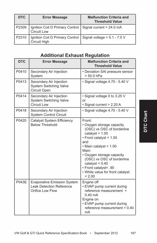
DTC
Cha
rt
VW Golf & GTI Quick Reference Specification Book • September 2012 187
DTC Error Message Malfunction Criteria and Threshold Value
P2309 Ignition Coil D Primary Control Circuit Low
Signal current > 24.0 mA
P2310 Ignition Coil D Primary Control Circuit High
Signal voltage > 5.1 - 7.0 V
Additional Exhaust RegulationDTC Error Message Malfunction Criteria and
Threshold ValueP0410 Secondary Air Injection
System• Deviation SAI pressure sensor
> 50.0 hPaP0413 Secondary Air Injection
System Switching Valve Circuit Open
• Signal voltage 4.70 - 5.40 V
P0414 Secondary Air Injection System Switching Valve Circuit Low
• Signal voltage 0 to 3.25 Vor• Signal current > 2.20 A
P0418 Secondary Air Injection System Control Circuit
• Signal voltage 4.70 - 5.40 V
P0420 Catalyst System Efficiency Below Threshold
Front: • Oxygen storage capacity
(OSC) vs OSC of borderline catalyst < 1.00
• Front catalyst < 1.50and• Main catalyst < 1.00Main: • Oxygen storage capacity
(OSC) vs OSC of borderline catalyst < 0.40
• Front catalyst< .90• While value for front catalyst
< 2.00P043E Evaporative Emission System
Leak Detection Reference Orifice Low Flow
Engine off• EVAP pump current during
reference measurement < 0.40 mA
Engine on• EVAP pump current during
reference measurement > 0.40 mA
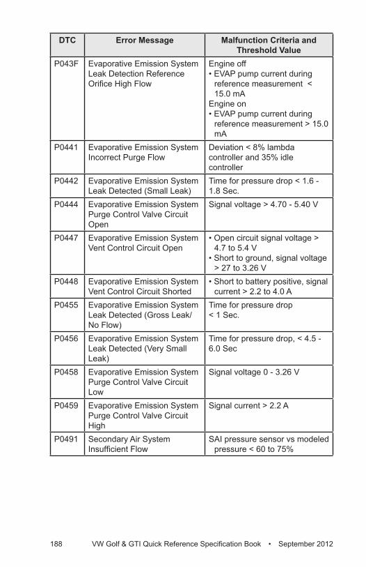
188 VW Golf & GTI Quick Reference Specification Book • September 2012
DTC Error Message Malfunction Criteria and Threshold Value
P043F Evaporative Emission System Leak Detection Reference Orifice High Flow
Engine off• EVAP pump current during
reference measurement < 15.0 mA
Engine on• EVAP pump current during
reference measurement > 15.0 mA
P0441 Evaporative Emission System Incorrect Purge Flow
Deviation < 8% lambda controller and 35% idle controller
P0442 Evaporative Emission System Leak Detected (Small Leak)
Time for pressure drop < 1.6 - 1.8 Sec.
P0444 Evaporative Emission System Purge Control Valve Circuit Open
Signal voltage > 4.70 - 5.40 V
P0447 Evaporative Emission System Vent Control Circuit Open
• Open circuit signal voltage > 4.7 to 5.4 V
• Short to ground, signal voltage > 27 to 3.26 V
P0448 Evaporative Emission System Vent Control Circuit Shorted
• Short to battery positive, signal current > 2.2 to 4.0 A
P0455 Evaporative Emission System Leak Detected (Gross Leak/No Flow)
Time for pressure drop < 1 Sec.
P0456 Evaporative Emission System Leak Detected (Very Small Leak)
Time for pressure drop, < 4.5 - 6.0 Sec
P0458 Evaporative Emission System Purge Control Valve Circuit Low
Signal voltage 0 - 3.26 V
P0459 Evaporative Emission System Purge Control Valve Circuit High
Signal current > 2.2 A
P0491 Secondary Air System Insufficient Flow
SAI pressure sensor vs modeled pressure < 60 to 75%
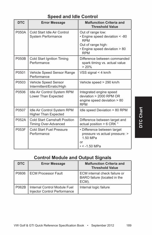
DTC
Cha
rt
VW Golf & GTI Quick Reference Specification Book • September 2012 189
Speed and Idle ControlDTC Error Message Malfunction Criteria and
Threshold ValueP050A Cold Start Idle Air Control
System PerformanceOut of range low:• Engine speed deviation < -80
RPMOut of range high:• Engine speed deviation > 80
RPMP050B Cold Start Ignition Timing
PerformanceDifference between commanded
spark timing vs. actual value > 20%
P0501 Vehicle Speed Sensor Range Performance
VSS signal < 4 km/h
P0503 Vehicle Speed Sensor Intermittent/Erratic/High
Vehicle speed > 290 km/h
P0506 Idle Air Control System RPM Lower Than Expected
Integrated engine speed deviation > 2000 RPM OR engine speed deviation > 80 RPM
P0507 Idle Air Control System RPM Higher Than Expected
Idle speed Deviation > 80 RPM
P052A Cold Start Camshaft Position Timing Over-Advanced
Difference between target and actual position > 6 CRK °
P053F Cold Start Fuel Pressure Performance
• Difference between target pressure vs actual pressure: > 1.50 MPa
or• < -1.50 MPa
Control Module and Output SignalsDTC Error Message Malfunction Criteria and
Threshold ValueP0606 ECM Processor Fault ECM internal check failure or
BARO failure (located in the ECM).
P062B Internal Control Module Fuel Injector Control Performance
Internal logic failure
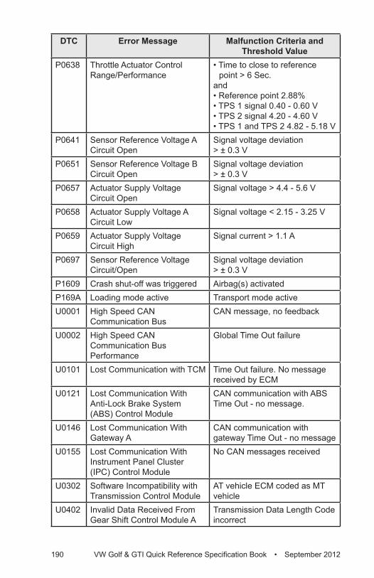
190 VW Golf & GTI Quick Reference Specification Book • September 2012
DTC Error Message Malfunction Criteria and Threshold Value
P0638 Throttle Actuator Control Range/Performance
• Time to close to reference point > 6 Sec.
and• Reference point 2.88%• TPS 1 signal 0.40 - 0.60 V• TPS 2 signal 4.20 - 4.60 V • TPS 1 and TPS 2 4.82 - 5.18 V
P0641 Sensor Reference Voltage A Circuit Open
Signal voltage deviation > ± 0.3 V
P0651 Sensor Reference Voltage B Circuit Open
Signal voltage deviation > ± 0.3 V
P0657 Actuator Supply Voltage Circuit Open
Signal voltage > 4.4 - 5.6 V
P0658 Actuator Supply Voltage A Circuit Low
Signal voltage < 2.15 - 3.25 V
P0659 Actuator Supply Voltage Circuit High
Signal current > 1.1 A
P0697 Sensor Reference Voltage Circuit/Open
Signal voltage deviation > ± 0.3 V
P1609 Crash shut-off was triggered Airbag(s) activatedP169A Loading mode active Transport mode activeU0001 High Speed CAN
Communication BusCAN message, no feedback
U0002 High Speed CAN Communication Bus Performance
Global Time Out failure
U0101 Lost Communication with TCM Time Out failure. No message received by ECM
U0121 Lost Communication With Anti-Lock Brake System (ABS) Control Module
CAN communication with ABS Time Out - no message.
U0146 Lost Communication With Gateway A
CAN communication with gateway Time Out - no message
U0155 Lost Communication With Instrument Panel Cluster (IPC) Control Module
No CAN messages received
U0302 Software Incompatibility with Transmission Control Module
AT vehicle ECM coded as MT vehicle
U0402 Invalid Data Received From Gear Shift Control Module A
Transmission Data Length Code incorrect
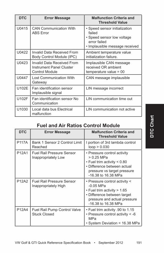
DTC
Cha
rt
VW Golf & GTI Quick Reference Specification Book • September 2012 191
DTC Error Message Malfunction Criteria and Threshold Value
U0415 CAN Communication With ABS Error
• Speed sensor initialization failed
• Speed sensor low voltage error failed
• Implausible message receivedU0422 Invalid Data Received From
Body Control Module (IPC)Ambient temperature value initialization failure.
U0423 Invalid Data Received From Instrument Panel Cluster Control Module
Implausible CAN message received OR ambient temperature value = 00
U0447 Lost Communication With Gateway
CAN message implausible
U102E Fan identification sensor Implausible signal
LIN message incorrect
U102F Fan identification sensor No Communication
LIN communication time out
U1030 Local data bus Electrical malfunction
LIN communication not active
Fuel and Air Ratios Control ModuleDTC Error Message Malfunction Criteria and
Threshold ValueP117A Bank 1 Sensor 2 Control Limit
ReachedI portion of 3rd lambda control
loop > 0.030P12A1 Fuel Rail Pressure Sensor
Inappropriately Low• Pressure control activity
> 0.25 MPa• Fuel trim activity < 0.80• Difference between actual
pressure vs target pressure -16.38 to 16.38 MPa
P12A2 Fuel Rail Pressure Sensor Inappropriately High
• Pressure control activity < -0.05 MPa
• Fuel trim activity > 1.65• Difference between target
pressure and actual pressure -16.38 to 16.38 MPa
P12A4 Fuel Rail Pump Control Valve Stuck Closed
• Fuel trim activity .90 to 1.15• Pressure control activity < -6
MPa• System Deviation < 16.38 MPa
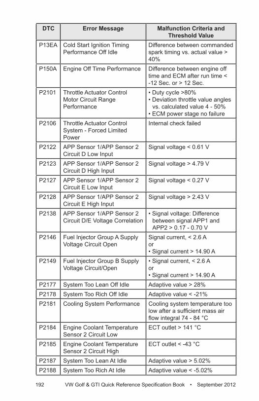
192 VW Golf & GTI Quick Reference Specification Book • September 2012
DTC Error Message Malfunction Criteria and Threshold Value
P13EA Cold Start Ignition Timing Performance Off Idle
Difference between commanded spark timing vs. actual value > 40%
P150A Engine Off Time Performance Difference between engine off time and ECM after run time < -12 Sec. or > 12 Sec.
P2101 Throttle Actuator Control Motor Circuit Range Performance
• Duty cycle >80%• Deviation throttle value angles
vs. calculated value 4 - 50%• ECM power stage no failure
P2106 Throttle Actuator Control System - Forced Limited Power
Internal check failed
P2122 APP Sensor 1/APP Sensor 2 Circuit D Low Input
Signal voltage < 0.61 V
P2123 APP Sensor 1/APP Sensor 2 Circuit D High Input
Signal voltage > 4.79 V
P2127 APP Sensor 1/APP Sensor 2 Circuit E Low Input
Signal voltage < 0.27 V
P2128 APP Sensor 1/APP Sensor 2 Circuit E High Input
Signal voltage > 2.43 V
P2138 APP Sensor 1/APP Sensor 2 Circuit D/E Voltage Correlation
• Signal voltage: Difference between signal APP1 and APP2 > 0.17 - 0.70 V
P2146 Fuel Injector Group A Supply Voltage Circuit Open
Signal current, < 2.6 Aor• Signal current > 14.90 A
P2149 Fuel Injector Group B Supply Voltage Circuit/Open
• Signal current, < 2.6 Aor• Signal current > 14.90 A
P2177 System Too Lean Off Idle Adaptive value > 28%P2178 System Too Rich Off Idle Adaptive value < -21%P2181 Cooling System Performance Cooling system temperature too
low after a sufficient mass air flow integral 74 - 84 °C
P2184 Engine Coolant Temperature Sensor 2 Circuit Low
ECT outlet > 141 °C
P2185 Engine Coolant Temperature Sensor 2 Circuit High
ECT outlet < -43 °C
P2187 System Too Lean At Idle Adaptive value > 5.02%P2188 System Too Rich At Idle Adaptive value < -5.02%
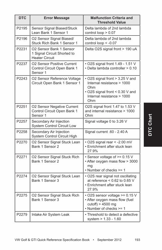
DTC
Cha
rt
VW Golf & GTI Quick Reference Specification Book • September 2012 193
DTC Error Message Malfunction Criteria and Threshold Value
P2195 Sensor Signal Biased/Stuck Lean Bank 1 Sensor 1
Delta lambda of 2nd lambda control loop > 0.07
P2196 O2 Sensor Signal Biased/Stuck Rich Bank 1 Sensor 1
Delta lambda of 2nd lambda control loop < -0.07
P2231 O2 Sensor Bank 1 Sensor 1 Signal Circuit Shorted to Heater Circuit
Delta O2S signal front > 190 uA
P2237 O2 Sensor Positive Current Control Circuit Open Bank 1 Sensor 1
• O2S signal front 1.49 - 1.51 V• Delta lambda controller > 0.10
P2243 O2 Sensor Reference Voltage Circuit Open Bank 1 Sensor 1
• O2S signal front > 3.25 V and Internal resistance > 1000 Ohm
• O2S signal front < 0.30 V and Internal resistance > 1000 Ohm
P2251 O2 Sensor Negative Current Control Circuit Open Bank 1 Sensor 1
O2S signal front 1.47 to 1.53 V and internal resistance > 1000 Ohm
P2257 Secondary Air Injection System Control Circuit Low
Signal voltage 0 to 3.26 V
P2258 Secondary Air Injection System Control Circuit High
Signal current .60 - 2.40 A
P2270 O2 Sensor Signal Stuck Lean Bank 1 Sensor 2
• O2S signal rear < -2.00 mV• Enrichment after stuck lean
27.9%P2271 O2 Sensor Signal Stuck Rich
Bank 1 Sensor 2• Sensor voltage of >= 0.15 V• After oxygen mass flow > 3000
mg• Number of checks >= 1
P2274 O2 Sensor Signal Stuck Lean Bank 1 Sensor 3
• O2S rear signal not oscillating at reference < 0.62 to 0.65 V
• Enrichment after stuck lean 27.9%
P2275 O2 Sensor Signal Stuck Rich Bank 1 Sensor 3
• O2S sensor voltage >= 0.15 V• After oxygen mass flow (fuel
cutoff) > 4500 mg• Number of checks >= 1
P2279 Intake Air System Leak • Threshold to detect a defective system > 1.33 - 1.60
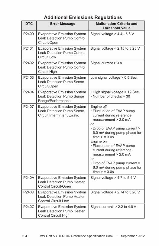
194 VW Golf & GTI Quick Reference Specification Book • September 2012
Additional Emissions RegulationsDTC Error Message Malfunction Criteria and
Threshold ValueP2400 Evaporative Emission System
Leak Detection Pump Control Circuit/Open
Signal voltage > 4.4 - 5.6 V
P2401 Evaporative Emission System Leak Detection Pump Control Circuit Low
Signal voltage < 2.15 to 3.25 V
P2402 Evaporative Emission System Leak Detection Pump Control Circuit High
Signal current > 3 A
P2403 Evaporative Emission System Leak Detection Pump Sense Circuit/Open
Low signal voltage > 0.5 Sec.
P2404 Evaporative Emission System Leak Detection Pump Sense Range/Performance
• High signal voltage > 12 Sec.• Number of checks = 30
P2407 Evaporative Emission System Leak Detection Pump Sense Circuit Intermittent/Erratic
Engine off• Fluctuation of EVAP pump
current during reference measurement > 2.0 mA
or• Drop of EVAP pump current >
6.0 mA during pump phase for time > = 3.0s
Engine on• Fluctuation of EVAP pump
current during reference measurement > 2.0 mA
or• Drop of EVAP pump current >
6.0 mA during pump phase for time > = 3.0s
P240A Evaporative Emission System Leak Detection Pump Heater Control Circuit/Open
Signal voltage > 4.7 to 5.4 V
P240B Evaporative Emission System Leak Detection Pump Heater Control Circuit Low
Signal voltage < 2.74 to 3.26 V
P240C Evaporative Emission System Leak Detection Pump Heater Control Circuit High
Signal current > 2.2 to 4.0 A
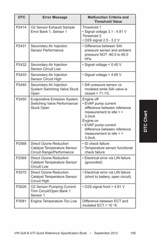
DTC
Cha
rt
VW Golf & GTI Quick Reference Specification Book • September 2012 195
DTC Error Message Malfunction Criteria and Threshold Value
P2414 O2 Sensor Exhaust Sample Error Bank 1, Sensor 1
Threshold 1• Signal voltage 3.1 - 4.81 VThreshold 2• O2S signal 2.5 - 3.2 V
P2431 Secondary Air Injection Sensor Performance
• Difference between SAI pressure sensor and ambient pressure NOT -60.0 to 60.0 hPa
P2432 Secondary Air Injection Sensor Circuit Low
• Signal voltage < 0.40 V
P2433 Secondary Air Injection Sensor Circuit High
• Signal voltage > 4.65 V
P2440 Secondary Air Injection System Switching Valve Stuck Open
• SAI pressure sensor vs modeled while SAI valve is closed < 71.1%
P2450 Evaporative Emission System Switching Valve Performance/Stuck Open
Engine off• EVAP pump current
difference between reference measurement to idle < = 3.0mA
Engine on• EVAP pump current
difference between reference measurement to idle < = 3.0mA
P2568 Direct Ozone Reduction Catalyst Temperature Sensor Circuit Range/Performance
• ID check failure• Temperature sensor functional
check failureP2569 Direct Ozone Reduction
Catalyst Temperature Sensor Circuit Low
• Electrical error via LIN failure (grounded)
P2570 Direct Ozone Reduction Catalyst Temperature Sensor Circuit High
• Electrical error via LIN failure (short to battery, open circuit)
P2626 O2 Sensor Pumping Current Trim Circuit/Open Bank 1 Sensor 1
• O2S signal front > 4.81 V
P3081 Engine Temperature Too Low Difference between ECT and modeled ECT > 10 °K
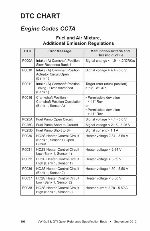
196 VW Golf & GTI Quick Reference Specification Book • September 2012
DTC CHART
Engine Codes CCTAFuel and Air Mixture,
Additional Emission RegulationsDTC Error Message Malfunction Criteria and
Threshold ValueP000A Intake (A) Camshaft Position
Slow Response Bank 1Signal change < 1.9 - 4.2°CRK/s
P0010 Intake (A) Camshaft Position Actuator Circuit/Open (Bank 1)
Signal voltage > 4.4 - 5.6 V
P0011 Intake (A) Camshaft Position Timing - Over-Advanced (Bank 1)
Target error (stuck position) > 6.8 - 8°CRK
P0016 Crankshaft Position - Camshaft Position Correlation (Bank 1, Sensor A)
• Permissible deviation < 11° Rev
or• Permissible deviation
> 11° RevP025A Fuel Pump Open Circuit Signal voltage > 4.4 - 5.6 V P025C Fuel Pump Short to Ground Signal voltage < 2.15 - 3.25 VP025D Fuel Pump Short to B+ Signal current > 1.1 AP0030 HO2S Heater Control Circuit
(Bank 1, Sensor 1) Open Circuit
Heater voltage 2.34 - 3.59 V
P0031 HO2S Heater Control Circuit Low (Bank 1, Sensor 1)
Heater voltage < 2.34 V
P0032 HO2S Heater Control Circuit High (Bank 1, Sensor 1)
Heater voltage > 3.59 V
P0036 HO2S Heater Control Circuit (Bank 1, Sensor 2)
Heater voltage 4.50 - 5.50 V
P0037 HO2S Heater Control Circuit Low (Bank 1, Sensor 2)
Heater voltage < 3.00 V
P0038 HO2S Heater Control Circuit High (Bank 1, Sensor 2)
Heater current 2.70 - 5.50 A
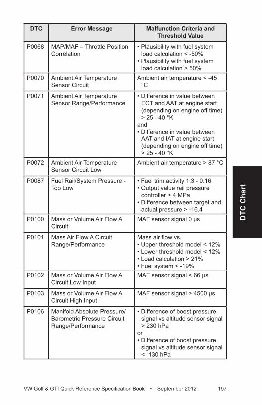
DTC
Cha
rt
VW Golf & GTI Quick Reference Specification Book • September 2012 197
DTC Error Message Malfunction Criteria and Threshold Value
P0068 MAP/MAF – Throttle Position Correlation
• Plausibility with fuel system load calculation < -50%
• Plausibility with fuel system load calculation > 50%
P0070 Ambient Air Temperature Sensor Circuit
Ambient air temperature < -45 °C
P0071 Ambient Air Temperature Sensor Range/Performance
• Difference in value between ECT and AAT at engine start (depending on engine off time) > 25 - 40 °K
and• Difference in value between
AAT and IAT at engine start (depending on engine off time) > 25 - 40 °K
P0072 Ambient Air Temperature Sensor Circuit Low
Ambient air temperature > 87 °C
P0087 Fuel Rail/System Pressure - Too Low
• Fuel trim activity 1.3 - 0.16• Output value rail pressure
controller > 4 MPa• Difference between target and
actual pressure > -16.4P0100 Mass or Volume Air Flow A
CircuitMAF sensor signal 0 µs
P0101 Mass Air Flow A Circuit Range/Performance
Mass air flow vs.• Upper threshold model < 12%• Lower threshold model < 12%• Load calculation > 21%• Fuel system < -19%
P0102 Mass or Volume Air Flow A Circuit Low Input
MAF sensor signal < 66 µs
P0103 Mass or Volume Air Flow A Circuit High Input
MAF sensor signal > 4500 µs
P0106 Manifold Absolute Pressure/Barometric Pressure Circuit Range/Performance
• Difference of boost pressure signal vs altitude sensor signal > 230 hPa
or• Difference of boost pressure
signal vs altitude sensor signal < -130 hPa
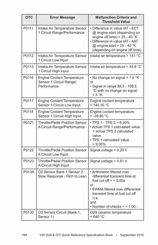
198 VW Golf & GTI Quick Reference Specification Book • September 2012
DTC Error Message Malfunction Criteria and Threshold Value
P0111 Intake Air Temperature Sensor 1 Circuit Range/Performance
• Difference in value IAT - ECT @ engine start (depending on engine off time) > 25 - 40 °K
• Difference in value IAT - AAT @ engine start < 25 - 40 °K (depending on engine off time)
P0112 Intake Air Temperature Sensor 1 Circuit Low Input
Intake air temperature > 141 °C
P0113 Intake Air Temperature Sensor 1 Circuit High Input
Intake air temperature < 45.8 °C
P0116 Engine Coolant Temperature Sensor 1 Circuit Range/Performance
• No change on signal < 1.5 °Kor• Signal in range 88.5 - 109.5
°C with no change on signal 1.5 °K
P0117 Engine Coolant Temperature Sensor 1 Circuit Low Input
Engine coolant temperature > 140.30 °C
P0118 Engine Coolant Temperature Sensor 1 Circuit High Input
Engine coolant temperature < -39.80 °C
P0121 Throttle/Pedal Position Sensor A Circuit Range/Performance
• TPS 1 - TPS 2 > 6.30% • Actual TPS 1 calculated value
> actual TPS 2 calculated value
• TPS 1 calculated value > 9.00%
P0122 Throttle/Pedal Position Sensor A Circuit Low Input
Signal voltage < 0.20 V
P0123 Throttle/Pedal Position Sensor A Circuit High Input
Signal voltage > 4.81 V
P013A O2 Sensor Bank 1 Sensor 2 Slow Response - Rich to Lean
• Arithmetric filtered max differential transient time at fuel cut off > = 0.50s
or• EWMA filtered max differential
transient time at fuel cut off n.a.
and• Number of checks > = 1.00 -
P0130 O2 Sensor Circuit (Bank 1, Sensor 1)
O2S ceramic temperature < 640 °C

DTC
Cha
rt
VW Golf & GTI Quick Reference Specification Book • September 2012 199
DTC Error Message Malfunction Criteria and Threshold Value
P0131 O2 Sensor Circuit (Bank 1, Sensor 1) Low Voltage
VM < 2.0 VUN < 1.75 VIA or IP > 0.30 V
P0132 O2 Sensor Circuit (Bank 1, Sensor 1) High Voltage
VM > 3 VUN > 4 VIA or IP > 1.5 V
P0138 O2 Circuit High Voltage (Bank 1, Sensor 2)
Signal voltage > 1.26 V
P0139 O2 Circuit Slow Response (Bank 1 Sensor 2)
• EWMA filtered transient time at fuel cut off > 0.4 Sec.
• In voltage range 201.2 - 401.4 mV
• Number of checks > 3P0140 O2 Circuit No Activity
Detected (Bank 1, Sensor 2)Signal voltage• Signal voltage 401.4 - 499 mVInternal resistance• > 40000 ohm
P0141 O2 Heater Circuit (Bank 1, Sensor 2) Out of Range
Heater resistance, 1404 - 13650 Ohm
P0169 Incorrect Fuel Composition • Fuel quantity incorrect• Fuel correction factor incorrect• Internal check failed
P0171 System Too Lean (Bank 1) At idle • Adaptive value > 5.02%At part-load • Adaptive value 21%
P0172 System Too Rich (Bank 1) At idle • Adaptive value < 5.02%
(< 6.0% only B8 ULEV)At part-load• Adaptive value < 21%
P0190 Fuel Rail Pressure Sensor A Circuit
Signal voltage > 4.8 V
P0191 Fuel Rail Control Valve, High Pressure Side
Actual pressure > 20.6 MPa
P0192 Fuel Rail Pressure Sensor A Circuit Low Input
Signal voltage < 0.2 V
P0201 Injector Circuit/Open - Cylinder 1
• Low side signal current < 2.1 A• Internal logic failure
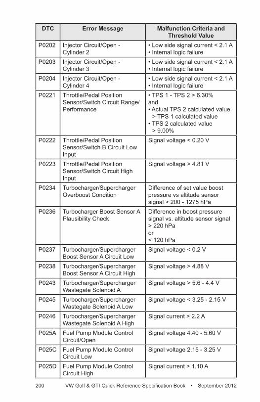
200 VW Golf & GTI Quick Reference Specification Book • September 2012
DTC Error Message Malfunction Criteria and Threshold Value
P0202 Injector Circuit/Open - Cylinder 2
• Low side signal current < 2.1 A• Internal logic failure
P0203 Injector Circuit/Open - Cylinder 3
• Low side signal current < 2.1 A• Internal logic failure
P0204 Injector Circuit/Open - Cylinder 4
• Low side signal current < 2.1 A• Internal logic failure
P0221 Throttle/Pedal Position Sensor/Switch Circuit Range/Performance
• TPS 1 - TPS 2 > 6.30%and• Actual TPS 2 calculated value
> TPS 1 calculated value• TPS 2 calculated value
> 9.00%P0222 Throttle/Pedal Position
Sensor/Switch B Circuit Low Input
Signal voltage < 0.20 V
P0223 Throttle/Pedal Position Sensor/Switch Circuit High Input
Signal voltage > 4.81 V
P0234 Turbocharger/Supercharger Overboost Condition
Difference of set value boost pressure vs altitude sensor signal > 200 - 1275 hPa
P0236 Turbocharger Boost Sensor A Plausibility Check
Difference in boost pressure signal vs. altitude sensor signal > 220 hPa or < 120 hPa
P0237 Turbocharger/Supercharger Boost Sensor A Circuit Low
Signal voltage < 0.2 V
P0238 Turbocharger/Supercharger Boost Sensor A Circuit High
Signal voltage > 4.88 V
P0243 Turbocharger/Supercharger Wastegate Solenoid A
Signal voltage > 5.6 - 4.4 V
P0245 Turbocharger/Supercharger Wastegate Solenoid A Low
Signal voltage < 3.25 - 2.15 V
P0246 Turbocharger/Supercharger Wastegate Solenoid A High
Signal current > 2.2 A
P025A Fuel Pump Module Control Circuit/Open
Signal voltage 4.40 - 5.60 V
P025C Fuel Pump Module Control Circuit Low
Signal voltage 2.15 - 3.25 V
P025D Fuel Pump Module Control Circuit High
Signal current > 1.10 A
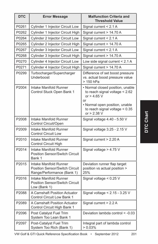
DTC
Cha
rt
VW Golf & GTI Quick Reference Specification Book • September 2012 201
DTC Error Message Malfunction Criteria and Threshold Value
P0261 Cylinder 1 Injector Circuit Low Signal current < 2.1 AP0262 Cylinder 1 Injector Circuit High Signal current > 14.70 AP0264 Cylinder 2 Injector Circuit Low Signal current < 2.1 AP0265 Cylinder 2 Injector Circuit High Signal current > 14.70 AP0267 Cylinder 3 Injector Circuit Low Signal current < 2.1 AP0268 Cylinder 3 Injector Circuit High Signal current > 14.70 AP0270 Cylinder 4 Injector Circuit Low Low side signal current < 2.1 AP0271 Cylinder 4 Injector Circuit High Signal current > 14.70 AP0299 Turbocharger/Supercharger
UnderboostDifference of set boost pressure vs. actual boost pressure value > 150 hPa
P2004 Intake Manifold Runner Control Stuck Open Bank 1
• Normal closed position, unable to reach signal voltage < 2.62 or > 4.65 V
or • Normal open position, unable
to reach signal voltage < 0.35 or > 2.38 V
P2008 Intake Manifold Runner Control Circuit/Open
Signal voltage 4.40 - 5.50 V
P2009 Intake Manifold Runner Control Circuit Low
Signal voltage 3.25 - 2.15 V
P2010 Intake Manifold Runner Control Circuit High
Signal current > 2.20 A
P2014 Intake Manifold Runner Position Sensor/Switch Circuit Bank 1
Signal voltage > 4.75 V
P2015 Intake Manifold Runner Position Sensor/Switch Circuit Range/Performance (Bank 1)
Deviation runner flap target position vs actual position > 25%
P2016 Intake Manifold Runner Position Sensor/Switch Circuit Low (Bank 1)
Signal voltage < 0.25 V
P2088 A Camshaft Position Actuator Control Circuit Low Bank 1
Signal voltage < 2.15 - 3.25 V
P2089 A Camshaft Position Actuator Control Circuit High Bank 1
Signal current > 2.2 A
P2096 Post Catalyst Fuel Trim System Too Lean Bank 1
Deviation lambda control < -0.03
P2097 Post-Catalyst Fuel Trim System Too Rich (Bank 1)
Integral part of lambda control > 0.03%
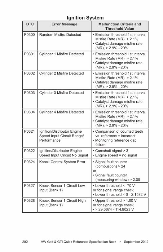
202 VW Golf & GTI Quick Reference Specification Book • September 2012
Ignition SystemDTC Error Message Malfunction Criteria and
Threshold ValueP0300 Random Misfire Detected • Emission threshold 1st interval
Misfire Rate (MR), > 2.1% • Catalyst damage misfire rate
(MR), > 2.9% - 20% P0301 Cylinder 1 Misfire Detected • Emission threshold 1st interval
Misfire Rate (MR), > 2.1%• Catalyst damage misfire rate
(MR), > 2.9% - 20% P0302 Cylinder 2 Misfire Detected • Emission threshold 1st interval
Misfire Rate (MR), > 2.1%• Catalyst damage misfire rate
(MR), > 2.9% - 20% P0303 Cylinder 3 Misfire Detected • Emission threshold 1st interval
Misfire Rate (MR), > 2.1%• Catalyst damage misfire rate
(MR), > 2.9% - 20% P0304 Cylinder 4 Misfire Detected • Emission threshold 1st interval
Misfire Rate (MR), > 2.1% • Catalyst damage misfire rate
(MR), > 2.9% - 20% P0321 Ignition/Distributor Engine
Speed Input Circuit Range/Performance
• Comparison of counted teeth vs. reference = incorrect
• Monitoring reference gap failure
P0322 Ignition/Distributor Engine Speed Input Circuit No Signal
• Camshaft signal > 3• Engine speed = no signal
P0324 Knock Control System Error • Signal fault counter (combustion) > 24
or • Signal fault counter
(measuring window) > 2.00P0327 Knock Sensor 1 Circuit Low
Input (Bank 1)• Lower threshold < -70 V or for signal range check• Lower threshold < 0 - 2.1582 V
P0328 Knock Sensor 1 Circuit High Input (Bank 1)
• Upper threshold > 1.00 Vor for signal range check • > 29.0674 - 114.9023 V
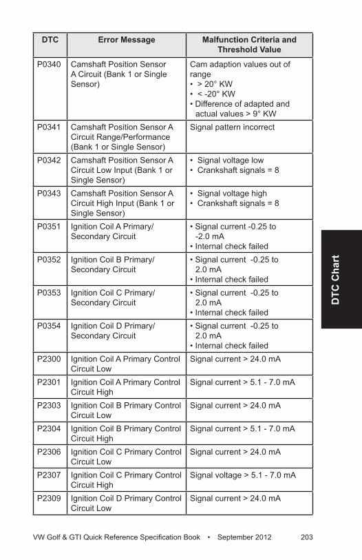
DTC
Cha
rt
VW Golf & GTI Quick Reference Specification Book • September 2012 203
DTC Error Message Malfunction Criteria and Threshold Value
P0340 Camshaft Position Sensor A Circuit (Bank 1 or Single Sensor)
Cam adaption values out of range • > 20° KW• < -20° KW• Difference of adapted and
actual values > 9° KWP0341 Camshaft Position Sensor A
Circuit Range/Performance (Bank 1 or Single Sensor)
Signal pattern incorrect
P0342 Camshaft Position Sensor A Circuit Low Input (Bank 1 or Single Sensor)
• Signal voltage low• Crankshaft signals = 8
P0343 Camshaft Position Sensor A Circuit High Input (Bank 1 or Single Sensor)
• Signal voltage high• Crankshaft signals = 8
P0351 Ignition Coil A Primary/Secondary Circuit
• Signal current -0.25 to -2.0 mA
• Internal check failedP0352 Ignition Coil B Primary/
Secondary Circuit• Signal current -0.25 to
2.0 mA• Internal check failed
P0353 Ignition Coil C Primary/Secondary Circuit
• Signal current -0.25 to 2.0 mA
• Internal check failedP0354 Ignition Coil D Primary/
Secondary Circuit• Signal current -0.25 to
2.0 mA • Internal check failed
P2300 Ignition Coil A Primary Control Circuit Low
Signal current > 24.0 mA
P2301 Ignition Coil A Primary Control Circuit High
Signal current > 5.1 - 7.0 mA
P2303 Ignition Coil B Primary Control Circuit Low
Signal current > 24.0 mA
P2304 Ignition Coil B Primary Control Circuit High
Signal current > 5.1 - 7.0 mA
P2306 Ignition Coil C Primary Control Circuit Low
Signal current > 24.0 mA
P2307 Ignition Coil C Primary Control Circuit High
Signal voltage > 5.1 - 7.0 mA
P2309 Ignition Coil D Primary Control Circuit Low
Signal current > 24.0 mA
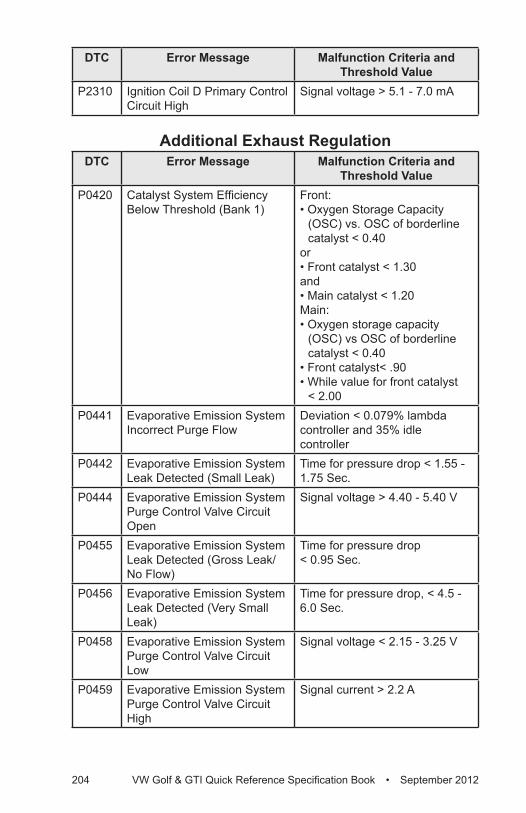
204 VW Golf & GTI Quick Reference Specification Book • September 2012
DTC Error Message Malfunction Criteria and Threshold Value
P2310 Ignition Coil D Primary Control Circuit High
Signal voltage > 5.1 - 7.0 mA
Additional Exhaust RegulationDTC Error Message Malfunction Criteria and
Threshold ValueP0420 Catalyst System Efficiency
Below Threshold (Bank 1)Front: • Oxygen Storage Capacity
(OSC) vs. OSC of borderline catalyst < 0.40
or• Front catalyst < 1.30and• Main catalyst < 1.20Main: • Oxygen storage capacity
(OSC) vs OSC of borderline catalyst < 0.40
• Front catalyst< .90• While value for front catalyst
< 2.00P0441 Evaporative Emission System
Incorrect Purge FlowDeviation < 0.079% lambda controller and 35% idle controller
P0442 Evaporative Emission System Leak Detected (Small Leak)
Time for pressure drop < 1.55 - 1.75 Sec.
P0444 Evaporative Emission System Purge Control Valve Circuit Open
Signal voltage > 4.40 - 5.40 V
P0455 Evaporative Emission System Leak Detected (Gross Leak/No Flow)
Time for pressure drop < 0.95 Sec.
P0456 Evaporative Emission System Leak Detected (Very Small Leak)
Time for pressure drop, < 4.5 - 6.0 Sec.
P0458 Evaporative Emission System Purge Control Valve Circuit Low
Signal voltage < 2.15 - 3.25 V
P0459 Evaporative Emission System Purge Control Valve Circuit High
Signal current > 2.2 A
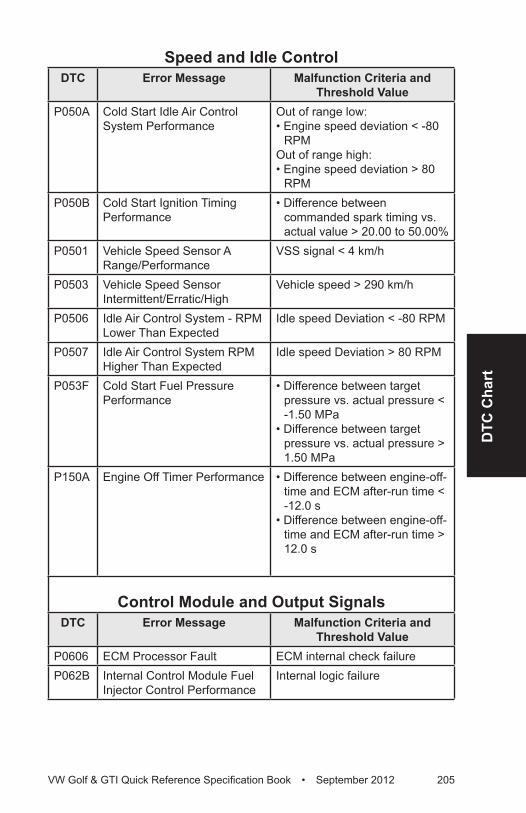
DTC
Cha
rt
VW Golf & GTI Quick Reference Specification Book • September 2012 205
Speed and Idle ControlDTC Error Message Malfunction Criteria and
Threshold ValueP050A Cold Start Idle Air Control
System PerformanceOut of range low:• Engine speed deviation < -80
RPMOut of range high:• Engine speed deviation > 80
RPMP050B Cold Start Ignition Timing
Performance• Difference between
commanded spark timing vs. actual value > 20.00 to 50.00%
P0501 Vehicle Speed Sensor A Range/Performance
VSS signal < 4 km/h
P0503 Vehicle Speed Sensor Intermittent/Erratic/High
Vehicle speed > 290 km/h
P0506 Idle Air Control System - RPM Lower Than Expected
Idle speed Deviation < -80 RPM
P0507 Idle Air Control System RPM Higher Than Expected
Idle speed Deviation > 80 RPM
P053F Cold Start Fuel Pressure Performance
• Difference between target pressure vs. actual pressure < -1.50 MPa
• Difference between target pressure vs. actual pressure > 1.50 MPa
P150A Engine Off Timer Performance • Difference between engine-off-time and ECM after-run time < -12.0 s
• Difference between engine-off-time and ECM after-run time > 12.0 s
Control Module and Output SignalsDTC Error Message Malfunction Criteria and
Threshold ValueP0606 ECM Processor Fault ECM internal check failureP062B Internal Control Module Fuel
Injector Control PerformanceInternal logic failure
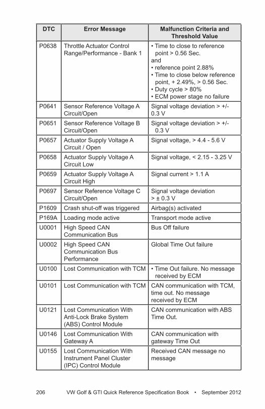
206 VW Golf & GTI Quick Reference Specification Book • September 2012
DTC Error Message Malfunction Criteria and Threshold Value
P0638 Throttle Actuator Control Range/Performance - Bank 1
• Time to close to reference point > 0.56 Sec.
and• reference point 2.88%• Time to close below reference
point, + 2.49%, > 0.56 Sec.• Duty cycle > 80%• ECM power stage no failure
P0641 Sensor Reference Voltage A Circuit/Open
Signal voltage deviation > +/- 0.3 V
P0651 Sensor Reference Voltage B Circuit/Open
Signal voltage deviation > +/- 0.3 V
P0657 Actuator Supply Voltage A Circuit / Open
Signal voltage, > 4.4 - 5.6 V
P0658 Actuator Supply Voltage A Circuit Low
Signal voltage, < 2.15 - 3.25 V
P0659 Actuator Supply Voltage A Circuit High
Signal current > 1.1 A
P0697 Sensor Reference Voltage C Circuit/Open
Signal voltage deviation > ± 0.3 V
P1609 Crash shut-off was triggered Airbag(s) activatedP169A Loading mode active Transport mode activeU0001 High Speed CAN
Communication BusBus Off failure
U0002 High Speed CAN Communication Bus Performance
Global Time Out failure
U0100 Lost Communication with TCM • Time Out failure. No message received by ECM
U0101 Lost Communication with TCM CAN communication with TCM, time out. No message received by ECM
U0121 Lost Communication With Anti-Lock Brake System (ABS) Control Module
CAN communication with ABS Time Out.
U0146 Lost Communication With Gateway A
CAN communication with gateway Time Out
U0155 Lost Communication With Instrument Panel Cluster (IPC) Control Module
Received CAN message no message
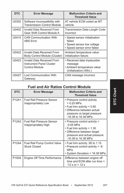
DTC
Cha
rt
VW Golf & GTI Quick Reference Specification Book • September 2012 207
DTC Error Message Malfunction Criteria and Threshold Value
U0302 Software Incompatibility with Transmission Control Module
AT vehicle ECM coded as MT vehicle
U0402 Invalid Data Received From Gear Shift Control Module A
Transmission Data Length Code incorrect
U0415 CAN Communication With ABS Error
• Speed sensor initialization failed
• Speed sensor low voltage • Speed sensor error failed
U0422 Invalid Data Received From Body Control Module (Cluster)
Ambient temperature value initialization failure.
U0423 Invalid Data Received From Instrument Panel Cluster Control Module
• Received data implausible message
• Ambient temperature value (initialization) 00h(-)
U0427 Lost Communication With Gateway
CAN message incorrect
Fuel and Air Ratios Control ModuleDTC Error Message Malfunction Criteria and
Threshold ValueP12A1 Fuel Rail Pressure Sensor
Inappropriately Low• Pressure control activity
> 0.25 MPa• Fuel trim activity < 0.80• Difference between actual
pressure vs target pressure -16.38 to 16.38 MPa
P12A2 Fuel Rail Pressure Sensor Inappropriately High
• Pressure control activity < -0.05 MPa
• Fuel trim activity > 1.30• Difference between target
pressure and actual pressure -16.38 to 16.38 MPa
P12A4 Fuel Rail Pump Control Valve Stuck Closed
• Fuel trim activity .90 to 1.15• Pressure control activity < -6
MPa• System Deviation < 16.38 MPa
P150A Engine Off Time Performance Difference between engine off time and ECM after run time < -12 s or > 12 s
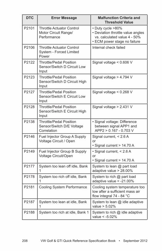
208 VW Golf & GTI Quick Reference Specification Book • September 2012
DTC Error Message Malfunction Criteria and Threshold Value
P2101 Throttle Actuator Control Motor Circuit Range/Performance
• Duty cycle >80%• Deviation throttle value angles
vs. calculated value 4 - 50%• ECM power stage no failure
P2106 Throttle Actuator Control System - Forced Limited Power
Internal check failed
P2122 Throttle/Pedal Position Sensor/Switch D Circuit Low Input
Signal voltage < 0.606 V
P2123 Throttle/Pedal Position Sensor/Switch D Circuit High Input
Signal voltage > 4.794 V
P2127 Throttle/Pedal Position Sensor/Switch E Circuit Low Input
Signal voltage < 0.268 V
P2128 Throttle/Pedal Position Sensor/Switch E Circuit High Input
Signal voltage > 2.431 V
P2138 Throttle/Pedal Position Sensor/Switch D/E Voltage Correlation
• Signal voltage: Difference between signal APP1 and APP2 > 0.167 - 0.703 V
P2146 Fuel Injector Group A Supply Voltage Circuit / Open
Signal current, < 2.6 Aor• Signal current > 14.70 A
P2149 Fuel Injector Group B Supply Voltage Circuit/Open
• Signal current, < 2.6 Aor• Signal current > 14.70 A
P2177 System too lean off idle, Bank 1
System to lean @ part load adaptive value > 28.00%
P2178 System too rich off idle, Bank 1
System to rich @ part load adaptive value < -21.00%
P2181 Cooling System Performance Cooling system temperature too low after a sufficient mass air flow integral 74 - 84 °C
P2187 System too lean at idle, Bank 1
System to lean @ idle adaptive value > 5.02%
P2188 System too rich at idle, Bank 1 System to rich @ idle adaptive value < -5.02%
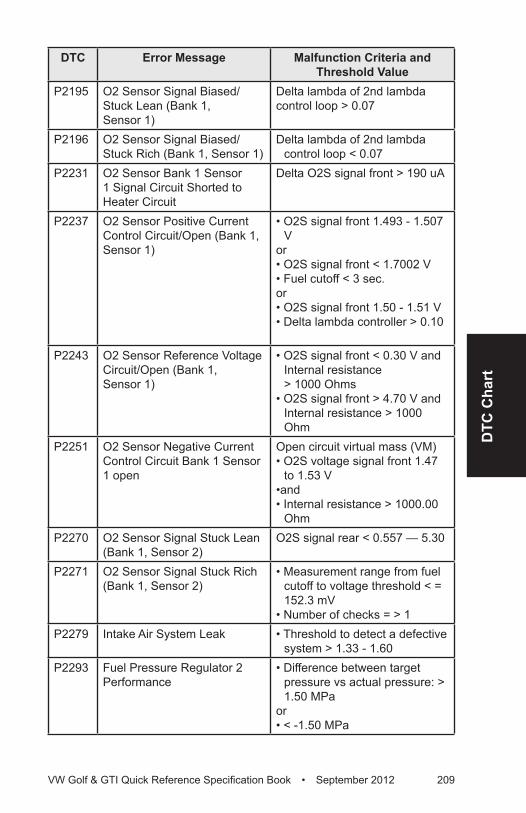
DTC
Cha
rt
VW Golf & GTI Quick Reference Specification Book • September 2012 209
DTC Error Message Malfunction Criteria and Threshold Value
P2195 O2 Sensor Signal Biased/Stuck Lean (Bank 1, Sensor 1)
Delta lambda of 2nd lambda control loop > 0.07
P2196 O2 Sensor Signal Biased/Stuck Rich (Bank 1, Sensor 1)
Delta lambda of 2nd lambda control loop < 0.07
P2231 O2 Sensor Bank 1 Sensor 1 Signal Circuit Shorted to Heater Circuit
Delta O2S signal front > 190 uA
P2237 O2 Sensor Positive Current Control Circuit/Open (Bank 1, Sensor 1)
• O2S signal front 1.493 - 1.507 V
or• O2S signal front < 1.7002 V• Fuel cutoff < 3 sec.or• O2S signal front 1.50 - 1.51 V• Delta lambda controller > 0.10
P2243 O2 Sensor Reference Voltage Circuit/Open (Bank 1, Sensor 1)
• O2S signal front < 0.30 V and Internal resistance > 1000 Ohms
• O2S signal front > 4.70 V and Internal resistance > 1000 Ohm
P2251 O2 Sensor Negative Current Control Circuit Bank 1 Sensor 1 open
Open circuit virtual mass (VM)• O2S voltage signal front 1.47
to 1.53 V•and • Internal resistance > 1000.00
OhmP2270 O2 Sensor Signal Stuck Lean
(Bank 1, Sensor 2)O2S signal rear < 0.557 — 5.30
P2271 O2 Sensor Signal Stuck Rich (Bank 1, Sensor 2)
• Measurement range from fuel cutoff to voltage threshold < = 152.3 mV
• Number of checks = > 1P2279 Intake Air System Leak • Threshold to detect a defective
system > 1.33 - 1.60P2293 Fuel Pressure Regulator 2
Performance• Difference between target
pressure vs actual pressure: > 1.50 MPa
or• < -1.50 MPa
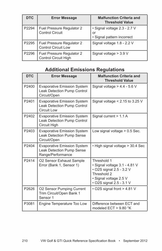
210 VW Golf & GTI Quick Reference Specification Book • September 2012
DTC Error Message Malfunction Criteria and Threshold Value
P2294 Fuel Pressure Regulator 2 Control Circuit
• Signal voltage 2.3 - 2.7 Vor• Signal pattern incorrect
P2295 Fuel Pressure Regulator 2 Control Circuit Low
Signal voltage 1.8 - 2.2 V
P2296 Fuel Pressure Regulator 2 Control Circuit High
Signal voltage > 3.9 V
Additional Emissions RegulationsDTC Error Message Malfunction Criteria and
Threshold ValueP2400 Evaporative Emission System
Leak Detection Pump Control Circuit/Open
Signal voltage > 4.4 - 5.6 V
P2401 Evaporative Emission System Leak Detection Pump Control Circuit Low
Signal voltage < 2.15 to 3.25 V
P2402 Evaporative Emission System Leak Detection Pump Control Circuit High
Signal current > 1.1 A
P2403 Evaporative Emission System Leak Detection Pump Sense Circuit/Open
Low signal voltage > 0.5 Sec.
P2404 Evaporative Emission System Leak Detection Pump Sense Range/Performance
• High signal voltage > 30.4 Sec
P2414 O2 Sensor Exhaust Sample Error (Bank 1, Sensor 1)
Threshold 1• Signal voltage 3.1 - 4.81 V• O2S signal 2.5 - 3.2 VThreshold 2• Signal voltage 2.5 V• O2S signal 2.5 - 3.1 V
P2626 O2 Sensor Pumping Current Trim Circuit/Open Bank 1 Sensor 1
• O2S signal front > 4.81 V
P3081 Engine Temperature Too Low Difference between ECT and modeled ECT > 9.80 °K
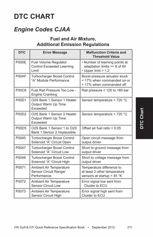
DTC
Cha
rt
VW Golf & GTI Quick Reference Specification Book • September 2012 211
DTC CHART
Engine Codes CJAA Fuel and Air Mixture,
Additional Emission RegulationsDTC Error Message Malfunction Criteria and
Threshold ValueP000E Fuel Volume Regulator
Control Exceeded Learning Limit
• Number of learning points at adaptation limits >= 8 of 64
• Upper limit > 1.2P00AF Turbocharger Boost Control
“A” Module PerformanceBoost pressure actuator stuck < 17% when commanded on or > 17% when commanded off.
P00C6 Fuel Rail Pressure Too Low - Engine Cranking
Rail pressure < 120 to 180 bar
P00D1 O2S Bank 1 Sensor 1 Heater Output Warm Up Time Exceeded
Sensor temperature < 720 °C
P00D2 O2S Bank 1 Sensor 2 Heater Output Warm Up Time Exceeded
Sensor temperature < 720 °C
P00D5 O2S Bank 1 Sensor 1 to O2S Bank 1 Sensor 2 Implausible
Offset air fuel ratio > 0.05
P0045 Turbocharger Boost Control Solenoid “A” Circuit Open
Open circuit message from output driver
P0047 Turbocharger Boost Control Solenoid “A” Circuit Low
Short to ground message from output driver
P0048 Turbocharger Boost Control Solenoid “A” Circuit High
Short to voltage message from output driver
P0071 Ambient Air Temperature Sensor Circuit Range/Performance
Temperature difference to at least 2 other temperature sensors at startup > 45 °K
P0072 Ambient Air Temperature Sensor Circuit Low
Error signal low sent from Cluster to ECU
P0073 Ambient Air Temperature Sensor Circuit High
Error signal high sent from Cluster to ECU
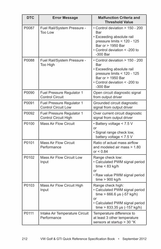
212 VW Golf & GTI Quick Reference Specification Book • September 2012
DTC Error Message Malfunction Criteria and Threshold Value
P0087 Fuel Rail/System Pressure - Too Low
• Control deviation > 150 - 200 Bar
• Exceeding absolute rail pressure limits < 120 - 125 Bar or > 1950 Bar
• Control deviation < -200 to -300 Bar
P0088 Fuel Rail/System Pressure - Too High
• Control deviation > 150 - 200 Bar
• Exceeding absolute rail pressure limits < 120 - 125 Bar or > 1950 Bar
• Control deviation < -200 to -300 Bar
P0090 Fuel Pressure Regulator 1 Control Circuit
Open circuit diagnostic signal from output driver
P0091 Fuel Pressure Regulator 1 Control Circuit Low
Grounded circuit diagnostic signal from output driver
P0092 Fuel Pressure Regulator 1 Control Circuit High
Over current circuit diagnostic signal from output driver
P0100 Mass Air Flow Circuit • Battery voltage < 7.5 Vor• Signal range check low,
battery voltage < 7.5 VP0101 Mass Air Flow Circuit
PerformanceRatio of actual mass airflow and modeled air mass > 1.80 or < 0.84
P0102 Mass Air Flow Circuit Low Input
Range check low: • Calculated PWM signal period
time < 83 kg/hor • Raw value PWM signal period
time > 900 kg/hP0103 Mass Air Flow Circuit High
InputRange check high: • Calculated PWM signal period
time > 666.6 µs (-57 kg/h)or• Calculated PWM signal period
time > 833.35 µs (-157 kg/h)P0111 Intake Air Temperature Circuit
PerformanceTemperature difference to at least 3 other temperature sensors at startup > 30 °K
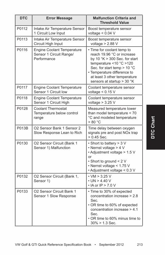
DTC
Cha
rt
VW Golf & GTI Quick Reference Specification Book • September 2012 213
DTC Error Message Malfunction Criteria and Threshold Value
P0112 Intake Air Temperature Sensor 1 Circuit Low Input
Boost temperature sensor voltage < 0.04 V
P0113 Intake Air Temperature Sensor Circuit High Input
Boost temperature sensor voltage > 2.88 V
P0116 Engine Coolant Temperature Sensor 1 Circuit Range/Performance
• Time for coolant temp to reach 19.96 °C or increase by 10 °K > 300 Sec. for start temperature <10 °C >120 Sec. for start temp > 10 °C
• Temperature difference to at least 3 other temperature sensors at startup > 30 °K
P0117 Engine Coolant Temperature Sensor 1 Circuit low
Coolant temperature sensor voltage < 0.15 V
P0118 Engine Coolant Temperature Sensor 1 Circuit High
Coolant temperature sensor voltage > 3.25 V
P0128 Coolant Thermostat Temperature below control range
Measured temperature lower than model temperature < 70 °C and modeled temperature > 80 °C
P013B O2 Sensor Bank 1 Sensor 2 Slow Response Lean to Rich
Time delay between oxygen signals pre and post NOx trap > 0.45 Sec.
P0130 O2 Sensor Circuit (Bank 1 Sensor 1) Malfunction
• Short to battery > 3 V• Nernst voltage > 4 V• Adjustment voltage > 1.5 Vor• Short to ground < 2 V• Nernst voltage < 1.75 V• Adjustment voltage < 0.3 V
P0132 O2 Sensor Circuit (Bank 1, Sensor 1)
• VM > 3.25 V• UN > 4.40 V• IA or IP > 7.0 V
P0133 O2 Sensor Circuit Bank 1 Sensor 1 Slow Response
• Time to 30% of expected concentration increase > 2.8 Sec.
• OR time to 60% of expected concentration increase > 4.1 Sec.
• OR time to 60% minus time to 30% > 1.3 Sec.
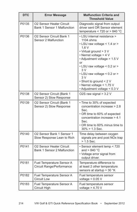
214 VW Golf & GTI Quick Reference Specification Book • September 2012
DTC Error Message Malfunction Criteria and Threshold Value
P0135 O2 Sensor Heater Circuit Bank 1 Sensor 1 Malfunction
Diagnostic signal from output driver sent OR Sensor element temperature < 720 or > 840 °C
P0136 O2 Sensor Circuit Bank 1 Sensor 2 Malfunction
• LSU internal resistance > 1104 ohms
• LSU raw voltage < 1.4 or > 1,6 V
• Virtual ground > 3 V• Nernst voltage > 4 V• Adjustment voltage > 1.5 Vor• LSU raw voltage < 0.2 or >
3 V• LSU raw voltage < 0.2 or >
3 V• Short to ground < 2 V• Nernst voltage < 1.75 V• Adjustment voltage < 0.3 V
P0138 O2 Sensor Circuit (Bank 1 Sensor 2) Slow Response
O2S raw signal > 3.2 V
P0139 O2 Sensor Circuit (Bank 1 Sensor 2) Slow Response
• Time to 30% of expected concentration increase > 2.8 Sec.
• OR time to 60% of expected concentration increase > 4.1 Sec.
• OR time to 60% minus time to 30% > 1.3 Sec.
P0140 O2 Sensor Bank 1 Sensor 1 Slow Response Lean to Rich
Time delay between oxygen signals pre and post NOx trap > 1.5 Sec.
P0141 O2 Sensor Heater Circuit Bank 1 Sensor 2 Malfunction
• Sensor element temp < 720 and > 840 °C
• Voltage error signal from output driver.
P0181 Fuel Temperature Sensor A Circuit Range/Performance
Temperature difference to at least 2 other temperature sensors at startup > 30 °K
P0182 Fuel Temperature Sensor A Circuit Low
Fuel temperature sensor voltage < 0.05 V
P0183 Fuel Temperature Sensor A Circuit High
Fuel temperature sensor voltage > 4.70 V
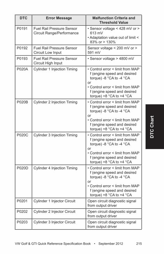
DTC
Cha
rt
VW Golf & GTI Quick Reference Specification Book • September 2012 215
DTC Error Message Malfunction Criteria and Threshold Value
P0191 Fuel Rail Pressure Sensor Circuit Range/Performance
• Sensor voltage < 428 mV or > 613 mV
• Adaptation value out of limit < 83% or > 130%
P0192 Fuel Rail Pressure Sensor Circuit Low Input
Sensor voltage < 200 mV or > 591 mV
P0193 Fuel Rail Pressure Sensor Circuit High Input
• Sensor voltage > 4800 mV
P020A Cylinder 1 Injection Timing • Control error < limit from MAP f (engine speed and desired torque) -8 °CA to -4 °CA
or• Control error < limit from MAP
f (engine speed and desired torque) +8 °CA to +4 °CA
P020B Cylinder 2 Injection Timing • Control error < limit from MAP f (engine speed and desired torque) -8 °CA to -4 °CA
or• Control error < limit from MAP
f (engine speed and desired torque) +8 °CA to +4 °CA
P020C Cylinder 3 Injection Timing • Control error < limit from MAP f (engine speed and desired torque) -8 °CA to -4 °CA
or• Control error < limit from MAP
f (engine speed and desired torque) +8 °CA to +4 °CA
P020D Cylinder 4 Injection Timing • Control error < limit from MAP f (engine speed and desired torque) -8 °CA to -4 °CA
or• Control error < limit from MAP
f (engine speed and desired torque) +8 °CA to +4 °CA
P0201 Cylinder 1 Injector Circuit Open circuit diagnostic signal from output driver
P0202 Cylinder 2 Injector Circuit Open circuit diagnostic signal from output driver
P0203 Cylinder 3 Injector Circuit Open circuit diagnostic signal from output driver
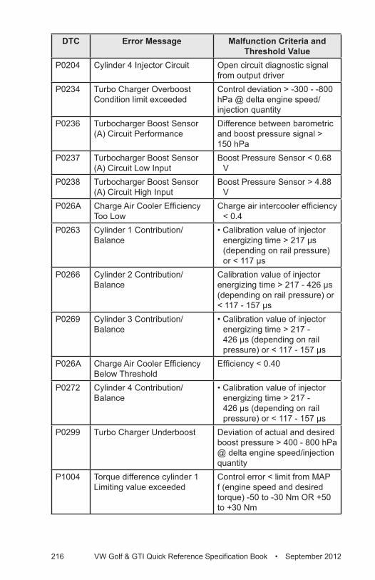
216 VW Golf & GTI Quick Reference Specification Book • September 2012
DTC Error Message Malfunction Criteria and Threshold Value
P0204 Cylinder 4 Injector Circuit Open circuit diagnostic signal from output driver
P0234 Turbo Charger Overboost Condition limit exceeded
Control deviation > -300 - -800 hPa @ delta engine speed/injection quantity
P0236 Turbocharger Boost Sensor (A) Circuit Performance
Difference between barometric and boost pressure signal > 150 hPa
P0237 Turbocharger Boost Sensor (A) Circuit Low Input
Boost Pressure Sensor < 0.68 V
P0238 Turbocharger Boost Sensor (A) Circuit High Input
Boost Pressure Sensor > 4.88 V
P026A Charge Air Cooler Efficiency Too Low
Charge air intercooler efficiency < 0.4
P0263 Cylinder 1 Contribution/Balance
• Calibration value of injector energizing time > 217 µs (depending on rail pressure) or < 117 µs
P0266 Cylinder 2 Contribution/Balance
Calibration value of injector energizing time > 217 - 426 µs (depending on rail pressure) or < 117 - 157 µs
P0269 Cylinder 3 Contribution/Balance
• Calibration value of injector energizing time > 217 - 426 µs (depending on rail pressure) or < 117 - 157 µs
P026A Charge Air Cooler Efficiency Below Threshold
Efficiency < 0.40
P0272 Cylinder 4 Contribution/Balance
• Calibration value of injector energizing time > 217 - 426 µs (depending on rail pressure) or < 117 - 157 µs
P0299 Turbo Charger Underboost Deviation of actual and desired boost pressure > 400 - 800 hPa @ delta engine speed/injection quantity
P1004 Torque difference cylinder 1 Limiting value exceeded
Control error < limit from MAP f (engine speed and desired torque) -50 to -30 Nm OR +50 to +30 Nm
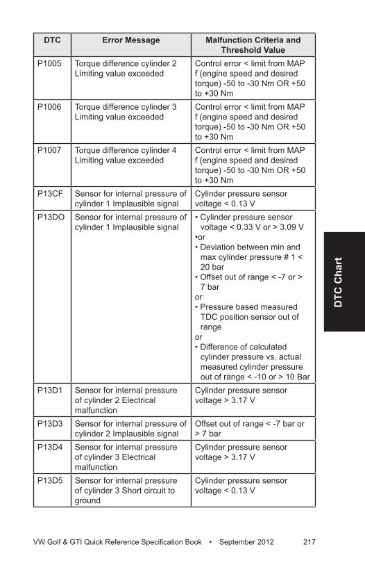
DTC
Cha
rt
VW Golf & GTI Quick Reference Specification Book • September 2012 217
DTC Error Message Malfunction Criteria and Threshold Value
P1005 Torque difference cylinder 2 Limiting value exceeded
Control error < limit from MAP f (engine speed and desired torque) -50 to -30 Nm OR +50 to +30 Nm
P1006 Torque difference cylinder 3 Limiting value exceeded
Control error < limit from MAP f (engine speed and desired torque) -50 to -30 Nm OR +50 to +30 Nm
P1007 Torque difference cylinder 4 Limiting value exceeded
Control error < limit from MAP f (engine speed and desired torque) -50 to -30 Nm OR +50 to +30 Nm
P13CF Sensor for internal pressure of cylinder 1 Implausible signal
Cylinder pressure sensor voltage < 0.13 V
P13DO Sensor for internal pressure of cylinder 1 Implausible signal
• Cylinder pressure sensor voltage < 0.33 V or > 3.09 V
•or• Deviation between min and
max cylinder pressure # 1 < 20 bar
• Offset out of range < -7 or > 7 bar
or• Pressure based measured
TDC position sensor out of range
or• Difference of calculated
cylinder pressure vs. actual measured cylinder pressure out of range < -10 or > 10 Bar
P13D1 Sensor for internal pressure of cylinder 2 Electrical malfunction
Cylinder pressure sensor voltage > 3.17 V
P13D3 Sensor for internal pressure of cylinder 2 Implausible signal
Offset out of range < -7 bar or > 7 bar
P13D4 Sensor for internal pressure of cylinder 3 Electrical malfunction
Cylinder pressure sensor voltage > 3.17 V
P13D5 Sensor for internal pressure of cylinder 3 Short circuit to ground
Cylinder pressure sensor voltage < 0.13 V
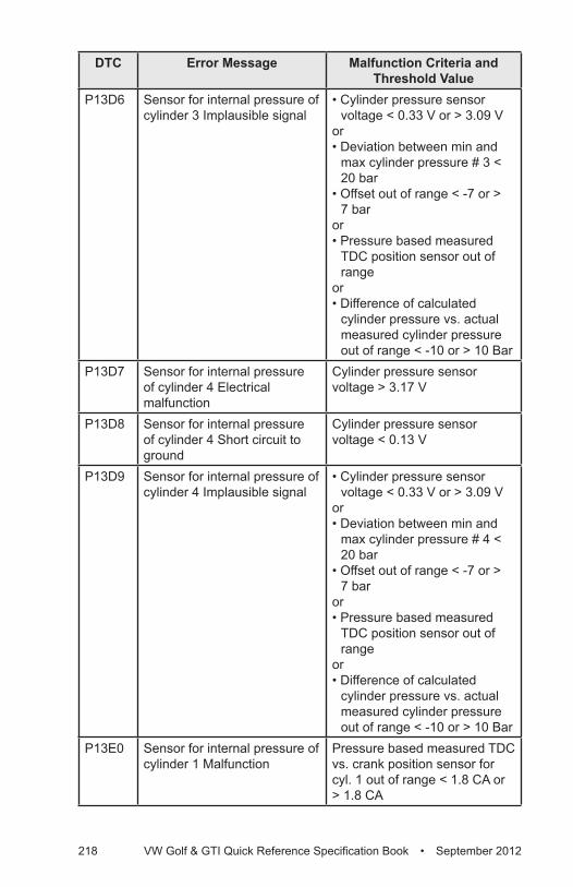
218 VW Golf & GTI Quick Reference Specification Book • September 2012
DTC Error Message Malfunction Criteria and Threshold Value
P13D6 Sensor for internal pressure of cylinder 3 Implausible signal
• Cylinder pressure sensor voltage < 0.33 V or > 3.09 V
or• Deviation between min and
max cylinder pressure # 3 < 20 bar
• Offset out of range < -7 or > 7 bar
or• Pressure based measured
TDC position sensor out of range
or• Difference of calculated
cylinder pressure vs. actual measured cylinder pressure out of range < -10 or > 10 Bar
P13D7 Sensor for internal pressure of cylinder 4 Electrical malfunction
Cylinder pressure sensor voltage > 3.17 V
P13D8 Sensor for internal pressure of cylinder 4 Short circuit to ground
Cylinder pressure sensor voltage < 0.13 V
P13D9 Sensor for internal pressure of cylinder 4 Implausible signal
• Cylinder pressure sensor voltage < 0.33 V or > 3.09 V
or• Deviation between min and
max cylinder pressure # 4 < 20 bar
• Offset out of range < -7 or > 7 bar
or• Pressure based measured
TDC position sensor out of range
or• Difference of calculated
cylinder pressure vs. actual measured cylinder pressure out of range < -10 or > 10 Bar
P13E0 Sensor for internal pressure of cylinder 1 Malfunction
Pressure based measured TDC vs. crank position sensor for cyl. 1 out of range < 1.8 CA or > 1.8 CA
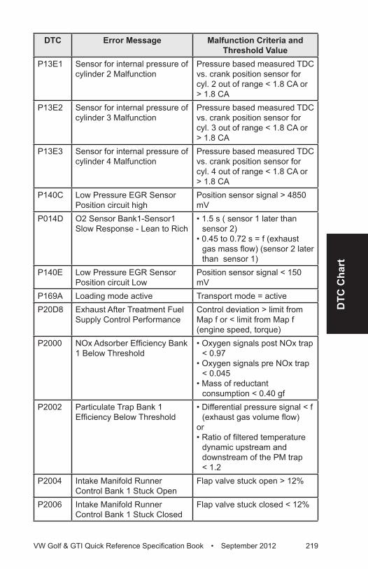
DTC
Cha
rt
VW Golf & GTI Quick Reference Specification Book • September 2012 219
DTC Error Message Malfunction Criteria and Threshold Value
P13E1 Sensor for internal pressure of cylinder 2 Malfunction
Pressure based measured TDC vs. crank position sensor for cyl. 2 out of range < 1.8 CA or > 1.8 CA
P13E2 Sensor for internal pressure of cylinder 3 Malfunction
Pressure based measured TDC vs. crank position sensor for cyl. 3 out of range < 1.8 CA or > 1.8 CA
P13E3 Sensor for internal pressure of cylinder 4 Malfunction
Pressure based measured TDC vs. crank position sensor for cyl. 4 out of range < 1.8 CA or > 1.8 CA
P140C Low Pressure EGR Sensor Position circuit high
Position sensor signal > 4850 mV
P014D O2 Sensor Bank1-Sensor1 Slow Response - Lean to Rich
• 1.5 s ( sensor 1 later than sensor 2)
• 0.45 to 0.72 s = f (exhaust gas mass flow) (sensor 2 later than sensor 1)
P140E Low Pressure EGR Sensor Position circuit Low
Position sensor signal < 150 mV
P169A Loading mode active Transport mode = activeP20D8 Exhaust After Treatment Fuel
Supply Control PerformanceControl deviation > limit from Map f or < limit from Map f (engine speed, torque)
P2000 NOx Adsorber Efficiency Bank 1 Below Threshold
• Oxygen signals post NOx trap < 0.97
• Oxygen signals pre NOx trap < 0.045
• Mass of reductant consumption < 0.40 gf
P2002 Particulate Trap Bank 1 Efficiency Below Threshold
• Differential pressure signal < f (exhaust gas volume flow)
or• Ratio of filtered temperature
dynamic upstream and downstream of the PM trap < 1.2
P2004 Intake Manifold Runner Control Bank 1 Stuck Open
Flap valve stuck open > 12%
P2006 Intake Manifold Runner Control Bank 1 Stuck Closed
Flap valve stuck closed < 12%
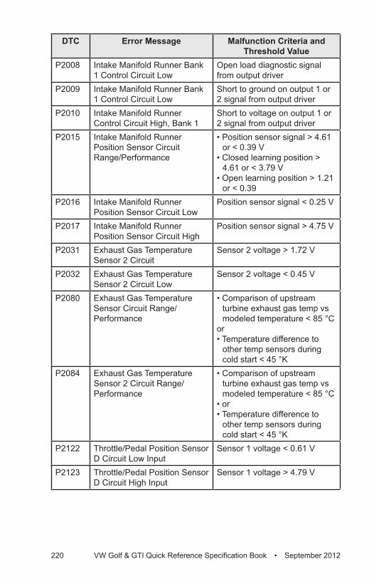
220 VW Golf & GTI Quick Reference Specification Book • September 2012
DTC Error Message Malfunction Criteria and Threshold Value
P2008 Intake Manifold Runner Bank 1 Control Circuit Low
Open load diagnostic signal from output driver
P2009 Intake Manifold Runner Bank 1 Control Circuit Low
Short to ground on output 1 or 2 signal from output driver
P2010 Intake Manifold Runner Control Circuit High, Bank 1
Short to voltage on output 1 or 2 signal from output driver
P2015 Intake Manifold Runner Position Sensor Circuit Range/Performance
• Position sensor signal > 4.61 or < 0.39 V
• Closed learning position > 4.61 or < 3.79 V
• Open learning position > 1.21 or < 0.39
P2016 Intake Manifold Runner Position Sensor Circuit Low
Position sensor signal < 0.25 V
P2017 Intake Manifold Runner Position Sensor Circuit High
Position sensor signal > 4.75 V
P2031 Exhaust Gas Temperature Sensor 2 Circuit
Sensor 2 voltage > 1.72 V
P2032 Exhaust Gas Temperature Sensor 2 Circuit Low
Sensor 2 voltage < 0.45 V
P2080 Exhaust Gas Temperature Sensor Circuit Range/Performance
• Comparison of upstream turbine exhaust gas temp vs modeled temperature < 85 °C
or• Temperature difference to
other temp sensors during cold start < 45 °K
P2084 Exhaust Gas Temperature Sensor 2 Circuit Range/Performance
• Comparison of upstream turbine exhaust gas temp vs modeled temperature < 85 °C
• or• Temperature difference to
other temp sensors during cold start < 45 °K
P2122 Throttle/Pedal Position Sensor D Circuit Low Input
Sensor 1 voltage < 0.61 V
P2123 Throttle/Pedal Position Sensor D Circuit High Input
Sensor 1 voltage > 4.79 V
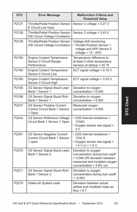
DTC
Cha
rt
VW Golf & GTI Quick Reference Specification Book • September 2012 221
DTC Error Message Malfunction Criteria and Threshold Value
P2127 Throttle/Pedal Position Sensor E Circuit Low Input
Sensor 2 voltage < 0.27 V
P2128 Throttle/Pedal Position Sensor D/E Circuit Voltage Correlation
Sensor 2 voltage > 2.43 V
P2138 Throttle/Pedal Position Sensor D/E Circuit Voltage Correlation
Voltage drift monitoring: • Throttle Position Sensor 1
voltage and APP Sensor 2 voltage = 13 - 20%
P2183 Engine Coolant Temperature Sensor 2 Circuit Range/Performance
Temperature difference to at least 2 other temperature sensors at startup > 20 °K
P2184 Engine Coolant Temperature Sensor 2 Circuit Low
ECT signal voltage < 0.15 V
P2185 Engine Coolant Temperature Sensor 2 Circuit High
ECT signal voltage > 3.25 V
P2195 O2 Sensor Signal Stuck Lean Bank 1 Sensor 1
Deviation to oxygen concentration > 0.046
P2196 O2 Sensor Signal Stuck Rich Bank 1 Sensor 1
Deviation to oxygen concentration < 0.063
P2237 O2 Sensor Positive Current Control Circuit Bank 1 Sensor 1 Open
Measured oxygen concentration < 0.005
P2243 O2 Sensor Reference Voltage Circuit Bank 1 Sensor 1 Open
• O2S internal resistance > 1104Ω
• Oxygen sensor raw signal > 3 V
P2251 O2 Sensor Negative Current Control Circuit Bank 1 Sensor 1 open
• O2S internal resistance > 1104 Ω
• Oxygen sensor raw signal < 1.4 V or > 1.6 V
P2270 O2 Sensor Signal Stuck Lean; Bank 1 Sensor 2
Deviation to oxygen concentration during fuel cutoff > 0.046 OR deviation between measured and modeled oxygen concentration > 4.8% vol.
P2271 O2 Sensor Signal Stuck Rich; Bank 1 Sensor 2
Deviation to oxygen concentration during fuel cutoff < -0.063
P2279 Intake Air System Leak Deviation between actual airflow and modeled mass air flow < 0.7
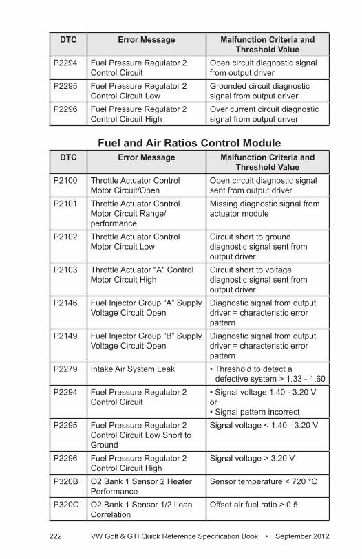
222 VW Golf & GTI Quick Reference Specification Book • September 2012
DTC Error Message Malfunction Criteria and Threshold Value
P2294 Fuel Pressure Regulator 2 Control Circuit
Open circuit diagnostic signal from output driver
P2295 Fuel Pressure Regulator 2 Control Circuit Low
Grounded circuit diagnostic signal from output driver
P2296 Fuel Pressure Regulator 2 Control Circuit High
Over current circuit diagnostic signal from output driver
Fuel and Air Ratios Control Module DTC Error Message Malfunction Criteria and
Threshold ValueP2100 Throttle Actuator Control
Motor Circuit/OpenOpen circuit diagnostic signal sent from output driver
P2101 Throttle Actuator Control Motor Circuit Range/performance
Missing diagnostic signal from actuator module
P2102 Throttle Actuator Control Motor Circuit Low
Circuit short to ground diagnostic signal sent from output driver
P2103 Throttle Actuator "A" Control Motor Circuit High
Circuit short to voltage diagnostic signal sent from output driver
P2146 Fuel Injector Group “A” Supply Voltage Circuit Open
Diagnostic signal from output driver = characteristic error pattern
P2149 Fuel Injector Group “B” Supply Voltage Circuit Open
Diagnostic signal from output driver = characteristic error pattern
P2279 Intake Air System Leak • Threshold to detect a defective system > 1.33 - 1.60
P2294 Fuel Pressure Regulator 2 Control Circuit
• Signal voltage 1.40 - 3.20 Vor• Signal pattern incorrect
P2295 Fuel Pressure Regulator 2 Control Circuit Low Short to Ground
Signal voltage < 1.40 - 3.20 V
P2296 Fuel Pressure Regulator 2 Control Circuit High
Signal voltage > 3.20 V
P320B O2 Bank 1 Sensor 2 Heater Performance
Sensor temperature < 720 °C
P320C O2 Bank 1 Sensor 1/2 Lean Correlation
Offset air fuel ratio > 0.5
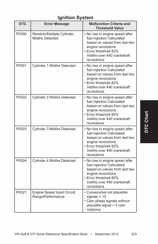
DTC
Cha
rt
VW Golf & GTI Quick Reference Specification Book • September 2012 223
Ignition SystemDTC Error Message Malfunction Criteria and
Threshold ValueP0300 Random/Multiple Cylinder.
Misfire Detected• No rise in engine speed after
fuel injection Calculated based on values from last two engine revolutions
• Error threshold 82% misfire over 440 crankshaft revolutions
P0301 Cylinder 1 Misfire Detected • No rise in engine speed after fuel injection Calculated based on values from last two engine revolutions
• Error threshold 82% misfire over 440 crankshaft revolutions
P0302 Cylinder 2 Misfire Detected • No rise in engine speed after fuel injection Calculated based on values from last two engine revolutions
• Error threshold 82% misfire over 440 crankshaft revolutions
P0303 Cylinder 3 Misfire Detected • No rise in engine speed after fuel injection Calculated based on values from last two engine revolutions
• Error threshold 82% misfire over 440 crankshaft revolutions
P0304 Cylinder 4 Misfire Detected • No rise in engine speed after fuel injection Calculated based on values from last two engine revolutions
• Error threshold 82% misfire over 440 crankshaft revolutions
P0321 Engine Speed Input Circuit Range/Performance
• Consecutive not plausible signals > 15
• Cam phase signals without plausible signal > 4 cam rotations.
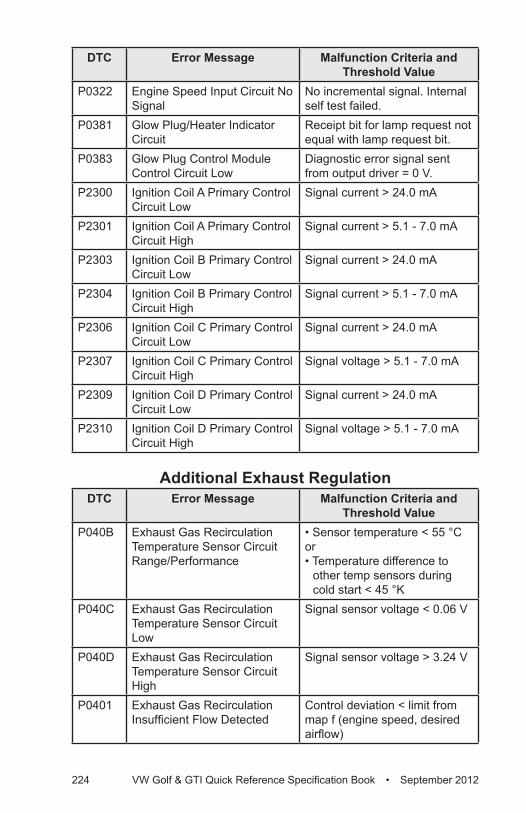
224 VW Golf & GTI Quick Reference Specification Book • September 2012
DTC Error Message Malfunction Criteria and Threshold Value
P0322 Engine Speed Input Circuit No Signal
No incremental signal. Internal self test failed.
P0381 Glow Plug/Heater Indicator Circuit
Receipt bit for lamp request not equal with lamp request bit.
P0383 Glow Plug Control Module Control Circuit Low
Diagnostic error signal sent from output driver = 0 V.
P2300 Ignition Coil A Primary Control Circuit Low
Signal current > 24.0 mA
P2301 Ignition Coil A Primary Control Circuit High
Signal current > 5.1 - 7.0 mA
P2303 Ignition Coil B Primary Control Circuit Low
Signal current > 24.0 mA
P2304 Ignition Coil B Primary Control Circuit High
Signal current > 5.1 - 7.0 mA
P2306 Ignition Coil C Primary Control Circuit Low
Signal current > 24.0 mA
P2307 Ignition Coil C Primary Control Circuit High
Signal voltage > 5.1 - 7.0 mA
P2309 Ignition Coil D Primary Control Circuit Low
Signal current > 24.0 mA
P2310 Ignition Coil D Primary Control Circuit High
Signal voltage > 5.1 - 7.0 mA
Additional Exhaust RegulationDTC Error Message Malfunction Criteria and
Threshold ValueP040B Exhaust Gas Recirculation
Temperature Sensor Circuit Range/Performance
• Sensor temperature < 55 °Cor• Temperature difference to
other temp sensors during cold start < 45 °K
P040C Exhaust Gas Recirculation Temperature Sensor Circuit Low
Signal sensor voltage < 0.06 V
P040D Exhaust Gas Recirculation Temperature Sensor Circuit High
Signal sensor voltage > 3.24 V
P0401 Exhaust Gas Recirculation Insufficient Flow Detected
Control deviation < limit from map f (engine speed, desired airflow)
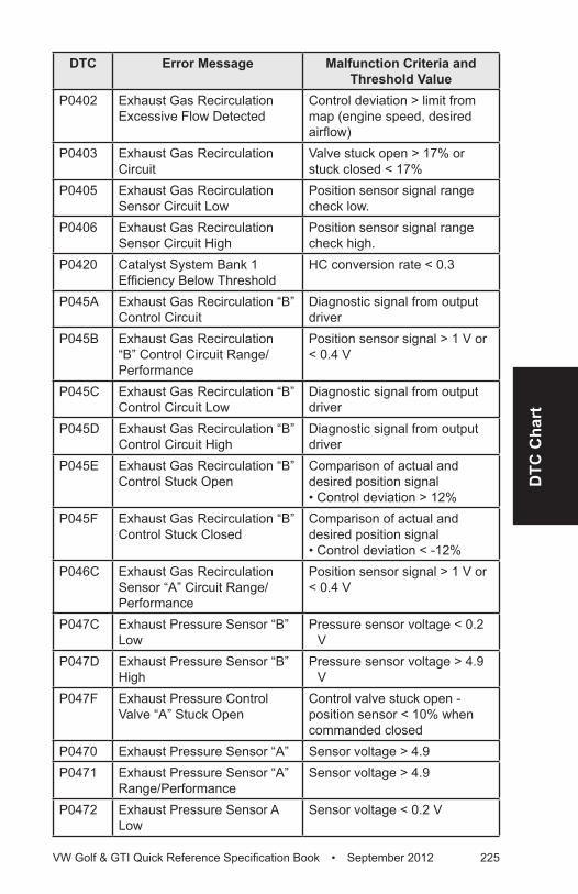
DTC
Cha
rt
VW Golf & GTI Quick Reference Specification Book • September 2012 225
DTC Error Message Malfunction Criteria and Threshold Value
P0402 Exhaust Gas Recirculation Excessive Flow Detected
Control deviation > limit from map (engine speed, desired airflow)
P0403 Exhaust Gas Recirculation Circuit
Valve stuck open > 17% or stuck closed < 17%
P0405 Exhaust Gas Recirculation Sensor Circuit Low
Position sensor signal range check low.
P0406 Exhaust Gas Recirculation Sensor Circuit High
Position sensor signal range check high.
P0420 Catalyst System Bank 1 Efficiency Below Threshold
HC conversion rate < 0.3
P045A Exhaust Gas Recirculation “B” Control Circuit
Diagnostic signal from output driver
P045B Exhaust Gas Recirculation “B” Control Circuit Range/Performance
Position sensor signal > 1 V or < 0.4 V
P045C Exhaust Gas Recirculation “B” Control Circuit Low
Diagnostic signal from output driver
P045D Exhaust Gas Recirculation “B” Control Circuit High
Diagnostic signal from output driver
P045E Exhaust Gas Recirculation “B” Control Stuck Open
Comparison of actual and desired position signal• Control deviation > 12%
P045F Exhaust Gas Recirculation “B” Control Stuck Closed
Comparison of actual and desired position signal• Control deviation < -12%
P046C Exhaust Gas Recirculation Sensor “A” Circuit Range/Performance
Position sensor signal > 1 V or < 0.4 V
P047C Exhaust Pressure Sensor “B” Low
Pressure sensor voltage < 0.2 V
P047D Exhaust Pressure Sensor “B” High
Pressure sensor voltage > 4.9 V
P047F Exhaust Pressure Control Valve “A” Stuck Open
Control valve stuck open - position sensor < 10% when commanded closed
P0470 Exhaust Pressure Sensor “A” Sensor voltage > 4.9P0471 Exhaust Pressure Sensor “A”
Range/PerformanceSensor voltage > 4.9
P0472 Exhaust Pressure Sensor A Low
Sensor voltage < 0.2 V
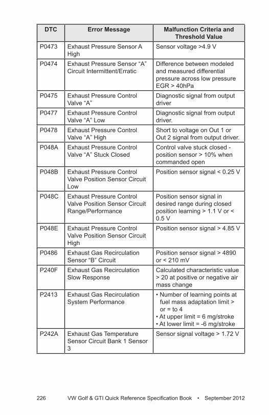
226 VW Golf & GTI Quick Reference Specification Book • September 2012
DTC Error Message Malfunction Criteria and Threshold Value
P0473 Exhaust Pressure Sensor A High
Sensor voltage >4.9 V
P0474 Exhaust Pressure Sensor “A” Circuit Intermittent/Erratic
Difference between modeled and measured differential pressure across low pressure EGR > 40hPa
P0475 Exhaust Pressure Control Valve “A”
Diagnostic signal from output driver
P0477 Exhaust Pressure Control Valve “A” Low
Diagnostic signal from output driver.
P0478 Exhaust Pressure Control Valve “A” High
Short to voltage on Out 1 or Out 2 signal from output driver.
P048A Exhaust Pressure Control Valve “A” Stuck Closed
Control valve stuck closed - position sensor > 10% when commanded open
P048B Exhaust Pressure Control Valve Position Sensor Circuit Low
Position sensor signal < 0.25 V
P048C Exhaust Pressure Control Valve Position Sensor Circuit Range/Performance
Position sensor signal in desired range during closed position learning > 1.1 V or < 0.5 V
P048E Exhaust Pressure Control Valve Position Sensor Circuit High
Position sensor signal > 4.85 V
P0486 Exhaust Gas Recirculation Sensor “B” Circuit
Position sensor signal > 4890 or < 210 mV
P240F Exhaust Gas Recirculation Slow Response
Calculated characteristic value > 20 at positive or negative air mass change
P2413 Exhaust Gas Recirculation System Performance
• Number of learning points at fuel mass adaptation limit > or = to 4
• At upper limit = 6 mg/stroke• At lower limit = -6 mg/stroke
P242A Exhaust Gas Temperature Sensor Circuit Bank 1 Sensor 3
Sensor signal voltage > 1.72 V

DTC
Cha
rt
VW Golf & GTI Quick Reference Specification Book • September 2012 227
DTC Error Message Malfunction Criteria and Threshold Value
P242B Exhaust Gas Temperature Sensor Circuit Bank 1 Sensor 3 Range/Performance
• Comparison of upstream turbine exhaust gas temp vs modeled temperature < 250 °C
or• Temperature difference to
other temp sensors during cold start < 45 °K
P242C Exhaust Gas Temperature Sensor Circuit Low Bank 1 Sensor 3
Sensor signal voltage < 0.45 V
P244C Exhaust Temperature Too Low For Particulate Filter Regeneration Bank 1
Time to activate control loop > 45 to 60 Sec.
P2452 Diesel Particulate Filter Differential Pressure Sensor Circuit
Sensor voltage > 4.9 V
P2453 Diesel Particulate Filter Differential Pressure Sensor Circuit Range/Performance
Differential pressure signal < -83 hPa to > 80 hPa
P2454 Diesel Particulate Filter Differential Pressure Sensor Circuit Low
Sensor voltage < 0.2
P2456 Diesel Particulate Filter Pressure Sensor “A” Circuit Intermittent/Erratic
• Inverse change of differential pressure per time > 10 hPa/s
• Inverse change of differential pressure per time < -10 hPa/s
P2457 Exhaust Gas Recirculation Cooling System Performance
Sensor temperature above threshold 40 °K
P2458 Diesel Particulate Filter Regeneration Duration
Regeneration time > 5400 Sec.
P2459 Diesel Particulate Filter Regeneration Frequency
PM trap loading > dynamically rising threshold [f(simulated engine emissions)]
P246E Exhaust Gas Temperature Sensor Circuit Bank 1 Sensor 4
Sensor signal voltage > 1.72 V
P246F Exhaust Gas Temperature Sensor Circuit Bank 1 Sensor 4 Range/Performance
• Sensor temperature < 230 °Cor• Temperature difference to other temp sensors during cold start < 45 °K
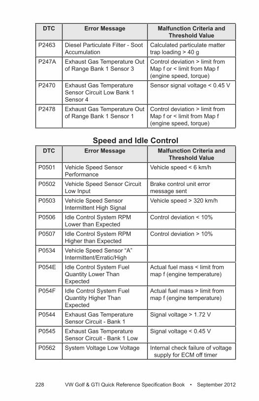
228 VW Golf & GTI Quick Reference Specification Book • September 2012
DTC Error Message Malfunction Criteria and Threshold Value
P2463 Diesel Particulate Filter - Soot Accumulation
Calculated particulate matter trap loading > 40 g
P247A Exhaust Gas Temperature Out of Range Bank 1 Sensor 3
Control deviation > limit from Map f or < limit from Map f (engine speed, torque)
P2470 Exhaust Gas Temperature Sensor Circuit Low Bank 1 Sensor 4
Sensor signal voltage < 0.45 V
P2478 Exhaust Gas Temperature Out of Range Bank 1 Sensor 1
Control deviation > limit from Map f or < limit from Map f (engine speed, torque)
Speed and Idle ControlDTC Error Message Malfunction Criteria and
Threshold ValueP0501 Vehicle Speed Sensor
PerformanceVehicle speed < 6 km/h
P0502 Vehicle Speed Sensor Circuit Low Input
Brake control unit error message sent
P0503 Vehicle Speed Sensor Intermittent High Signal
Vehicle speed > 320 km/h
P0506 Idle Control System RPM Lower than Expected
Control deviation < 10%
P0507 Idle Control System RPM Higher than Expected
Control deviation > 10%
P0534 Vehicle Speed Sensor “A” Intermittent/Erratic/High
P054E Idle Control System Fuel Quantity Lower Than Expected
Actual fuel mass < limit from map f (engine temperature)
P054F Idle Control System Fuel Quantity Higher Than Expected
Actual fuel mass > limit from map f (engine temperature)
P0544 Exhaust Gas Temperature Sensor Circuit - Bank 1
Signal voltage > 1.72 V
P0545 Exhaust Gas Temperature Sensor Circuit - Bank 1 Low
Signal voltage < 0.45 V
P0562 System Voltage Low Voltage Internal check failure of voltage supply for ECM off timer
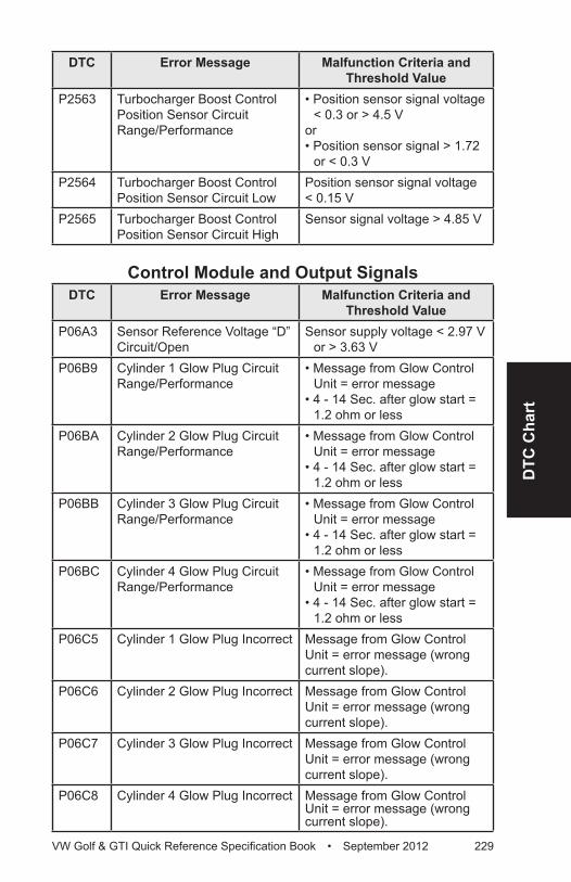
DTC
Cha
rt
VW Golf & GTI Quick Reference Specification Book • September 2012 229
DTC Error Message Malfunction Criteria and Threshold Value
P2563 Turbocharger Boost Control Position Sensor Circuit Range/Performance
• Position sensor signal voltage < 0.3 or > 4.5 V
or• Position sensor signal > 1.72
or < 0.3 VP2564 Turbocharger Boost Control
Position Sensor Circuit LowPosition sensor signal voltage < 0.15 V
P2565 Turbocharger Boost Control Position Sensor Circuit High
Sensor signal voltage > 4.85 V
Control Module and Output SignalsDTC Error Message Malfunction Criteria and
Threshold ValueP06A3 Sensor Reference Voltage “D”
Circuit/OpenSensor supply voltage < 2.97 V
or > 3.63 VP06B9 Cylinder 1 Glow Plug Circuit
Range/Performance• Message from Glow Control
Unit = error message• 4 - 14 Sec. after glow start =
1.2 ohm or lessP06BA Cylinder 2 Glow Plug Circuit
Range/Performance• Message from Glow Control
Unit = error message• 4 - 14 Sec. after glow start =
1.2 ohm or lessP06BB Cylinder 3 Glow Plug Circuit
Range/Performance• Message from Glow Control
Unit = error message• 4 - 14 Sec. after glow start =
1.2 ohm or lessP06BC Cylinder 4 Glow Plug Circuit
Range/Performance• Message from Glow Control
Unit = error message• 4 - 14 Sec. after glow start =
1.2 ohm or lessP06C5 Cylinder 1 Glow Plug Incorrect Message from Glow Control
Unit = error message (wrong current slope).
P06C6 Cylinder 2 Glow Plug Incorrect Message from Glow Control Unit = error message (wrong current slope).
P06C7 Cylinder 3 Glow Plug Incorrect Message from Glow Control Unit = error message (wrong current slope).
P06C8 Cylinder 4 Glow Plug Incorrect Message from Glow Control Unit = error message (wrong current slope).
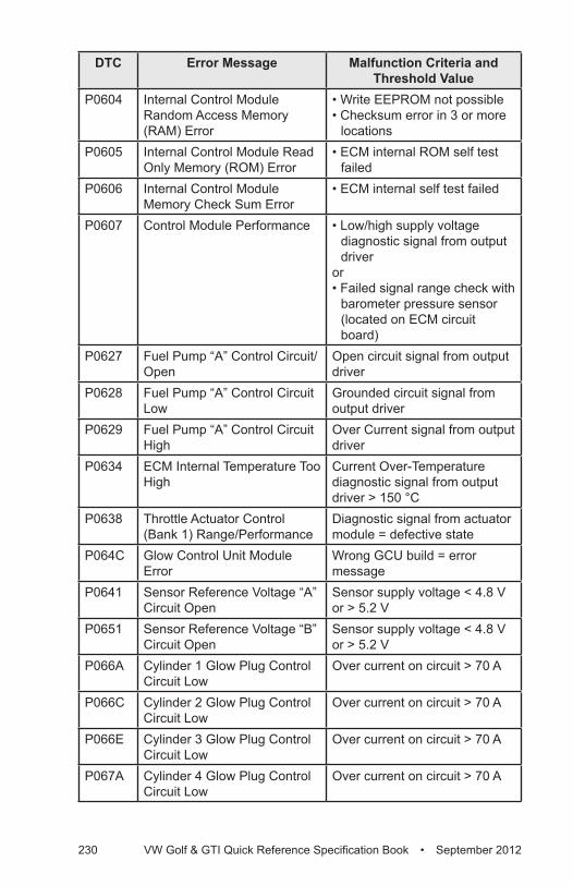
230 VW Golf & GTI Quick Reference Specification Book • September 2012
DTC Error Message Malfunction Criteria and Threshold Value
P0604 Internal Control Module Random Access Memory (RAM) Error
• Write EEPROM not possible• Checksum error in 3 or more
locationsP0605 Internal Control Module Read
Only Memory (ROM) Error• ECM internal ROM self test
failed P0606 Internal Control Module
Memory Check Sum Error • ECM internal self test failed
P0607 Control Module Performance • Low/high supply voltage diagnostic signal from output driver
or• Failed signal range check with
barometer pressure sensor (located on ECM circuit board)
P0627 Fuel Pump “A” Control Circuit/Open
Open circuit signal from output driver
P0628 Fuel Pump “A” Control Circuit Low
Grounded circuit signal from output driver
P0629 Fuel Pump “A” Control Circuit High
Over Current signal from output driver
P0634 ECM Internal Temperature Too High
Current Over-Temperature diagnostic signal from output driver > 150 °C
P0638 Throttle Actuator Control (Bank 1) Range/Performance
Diagnostic signal from actuator module = defective state
P064C Glow Control Unit Module Error
Wrong GCU build = error message
P0641 Sensor Reference Voltage “A” Circuit Open
Sensor supply voltage < 4.8 V or > 5.2 V
P0651 Sensor Reference Voltage “B” Circuit Open
Sensor supply voltage < 4.8 V or > 5.2 V
P066A Cylinder 1 Glow Plug Control Circuit Low
Over current on circuit > 70 A
P066C Cylinder 2 Glow Plug Control Circuit Low
Over current on circuit > 70 A
P066E Cylinder 3 Glow Plug Control Circuit Low
Over current on circuit > 70 A
P067A Cylinder 4 Glow Plug Control Circuit Low
Over current on circuit > 70 A
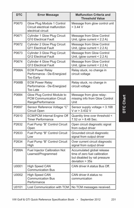
DTC
Cha
rt
VW Golf & GTI Quick Reference Specification Book • September 2012 231
DTC Error Message Malfunction Criteria and Threshold Value
P0670 Glow Plug Module 1 Control Circuit electrical malfunction electrical circuit
Message from glow control unit = 3.44 V
P0671 Cylinder 1 Glow Plug Circuit Q10 Electrical Fault
Message from Glow Control Unit, (glow current < 2.2 A)
P0672 Cylinder 2 Glow Plug Circuit Q11 Electrical Fault
Message from Glow Control Unit, (glow current < 2.2 A)
P0673 Cylinder 3 Glow Plug Circuit Q12 Electrical Fault
Message from Glow Control Unit, (glow current < 2.2 A)
P0674 Cylinder 4 Glow Plug Circuit Q13 Electrical Fault
Message from Glow Control Unit, (glow current < 2.2 A)
P068A ECM Power Relay Performance - De-Energized Too Early
Relay stuck, no change in circuit voltage
P068B ECM Power Relay Performance - De-Energized Too Late
Relay stuck, no change in circuit voltage
P0684 Glow Plug Control Module to PCM Communication Circuit Range/Performance
Message from glow relay- missing info from Glow Control Unit
P0697 Sensor Reference Voltage “C” Circuit Open
Sensor supply voltage < 3.168 V or > 3.432 V
P2610 ECM/PCM Internal Engine Off Timer Performance
Quantity time over threshold < 7.52 or > 8.48 Sec.
P2632 Fuel Pump “B” Control Circuit Open
Open circuit diagnostic signal from output driver
P2633 Fuel Pump “B” Control Circuit Low
Grounded circuit diagnostic signal from output driver
P2634 Fuel Pump “B” Control Circuit High
Over current circuit diagnostic signal from output driver
P268A Fuel Injector Calibration Not Learned/Programmed
Accumulated global release time of zero fuel calibration but disabled by rail pressure deviation > 35s
U0001 High Speed CAN Communication Bus
CAN driver A status Bus Off.
U0002 High Speed CAN Communication Bus Performance
CAN driver A status no communication
U0101 Lost Communication with TCM No TCM messages received.
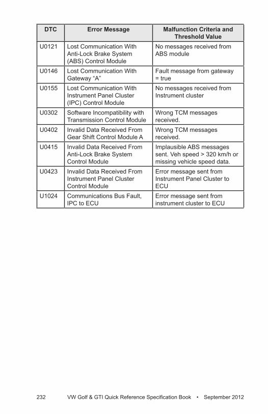
232 VW Golf & GTI Quick Reference Specification Book • September 2012
DTC Error Message Malfunction Criteria and Threshold Value
U0121 Lost Communication With Anti-Lock Brake System (ABS) Control Module
No messages received from ABS module
U0146 Lost Communication With Gateway “A”
Fault message from gateway = true
U0155 Lost Communication With Instrument Panel Cluster (IPC) Control Module
No messages received from Instrument cluster
U0302 Software Incompatibility with Transmission Control Module
Wrong TCM messages received.
U0402 Invalid Data Received From Gear Shift Control Module A
Wrong TCM messages received.
U0415 Invalid Data Received From Anti-Lock Brake System Control Module
Implausible ABS messages sent. Veh speed > 320 km/h or missing vehicle speed data.
U0423 Invalid Data Received From Instrument Panel Cluster Control Module
Error message sent from Instrument Panel Cluster to ECU
U1024 Communications Bus Fault, IPC to ECU
Error message sent from instrument cluster to ECU

DTC
Cha
rt
VW Golf & GTI Quick Reference Specification Book • September 2012 233
DTC CHART
Engine Codes CRZAFuel and Air Mixture,
Additional Emission RegulationsDTC Error Message Malfunction Criteria and
Threshold ValueP000A Camshaft Position Slow
Response Difference between target and actual position > 8 °CRK for > 1.3 to 2.9 Sec. and adjustment angle >= 2.50 °CRK
P0010 Camshaft Position Actuator Circuit Open
Signal voltage, > 4.70 - 5.40 V
P0011 Camshaft Position Timing - Over-Advanced
• Difference between target and actual position > 8 CRK °• Adjustment angle < 2.50 CRK °
P0016 Crankshaft Position vs. Camshaft Position Correlation
• Permissible deviation < 11° Rev
or• Permissible deviation
> 11° RevP0036 HO2S Heater Control Circuit
(Bank 1, Sensor 2) OpenHeater voltage 2.34 to 3.59 V
P0037 HO2S Heater Control Circuit Low (Bank 1, Sensor 2)
Heater voltage < 2.34 V
P0038 HO2S Heater Control Circuit High (Bank 1, Sensor 2)
Heater voltage > 3.59 V
P008A Low Pressure Fuel System Pressure Too Low
Actual pressure < 0.08 MPa
P008B Low Pressure Fuel System Pressure Too High
Actual pressure > 0.8 MPa
P0087 Fuel Rail/System Pressure - Too Low
• Fuel trim activity 0.90 - 1.15• Output value rail pressure controller > 2 MPa• Difference between target and
actual pressure > -16.38P0089 Fuel Pressure Regulator
Performance• Difference between target and actual pressure > 0.15 and < -0.2 MPa• Total pressure controller response < -0.25 and > 0.35 MPa
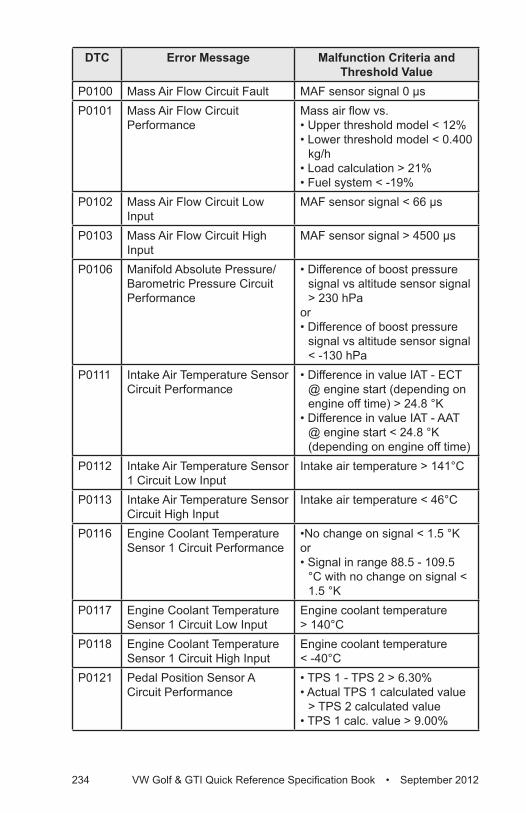
234 VW Golf & GTI Quick Reference Specification Book • September 2012
DTC Error Message Malfunction Criteria and Threshold Value
P0100 Mass Air Flow Circuit Fault MAF sensor signal 0 µsP0101 Mass Air Flow Circuit
PerformanceMass air flow vs.• Upper threshold model < 12%• Lower threshold model < 0.400
kg/h• Load calculation > 21%• Fuel system < -19%
P0102 Mass Air Flow Circuit Low Input
MAF sensor signal < 66 µs
P0103 Mass Air Flow Circuit High Input
MAF sensor signal > 4500 µs
P0106 Manifold Absolute Pressure/Barometric Pressure Circuit Performance
• Difference of boost pressure signal vs altitude sensor signal > 230 hPa
or• Difference of boost pressure
signal vs altitude sensor signal < -130 hPa
P0111 Intake Air Temperature Sensor Circuit Performance
• Difference in value IAT - ECT @ engine start (depending on engine off time) > 24.8 °K
• Difference in value IAT - AAT @ engine start < 24.8 °K (depending on engine off time)
P0112 Intake Air Temperature Sensor 1 Circuit Low Input
Intake air temperature > 141°C
P0113 Intake Air Temperature Sensor Circuit High Input
Intake air temperature < 46°C
P0116 Engine Coolant Temperature Sensor 1 Circuit Performance
•No change on signal < 1.5 °Kor • Signal in range 88.5 - 109.5
°C with no change on signal < 1.5 °K
P0117 Engine Coolant Temperature Sensor 1 Circuit Low Input
Engine coolant temperature > 140°C
P0118 Engine Coolant Temperature Sensor 1 Circuit High Input
Engine coolant temperature < -40°C
P0121 Pedal Position Sensor A Circuit Performance
• TPS 1 - TPS 2 > 6.30% • Actual TPS 1 calculated value
> TPS 2 calculated value• TPS 1 calc. value > 9.00%
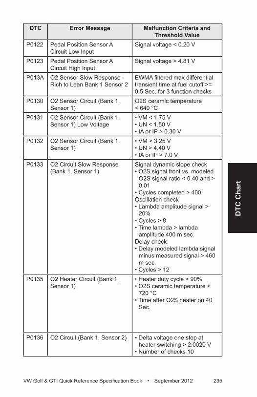
DTC
Cha
rt
VW Golf & GTI Quick Reference Specification Book • September 2012 235
DTC Error Message Malfunction Criteria and Threshold Value
P0122 Pedal Position Sensor A Circuit Low Input
Signal voltage < 0.20 V
P0123 Pedal Position Sensor A Circuit High Input
Signal voltage > 4.81 V
P013A O2 Sensor Slow Response - Rich to Lean Bank 1 Sensor 2
EWMA filtered max differential transient time at fuel cutoff >= 0.5 Sec. for 3 function checks
P0130 O2 Sensor Circuit (Bank 1, Sensor 1)
O2S ceramic temperature < 640 °C
P0131 O2 Sensor Circuit (Bank 1, Sensor 1) Low Voltage
• VM < 1.75 V• UN < 1.50 V• IA or IP > 0.30 V
P0132 O2 Sensor Circuit (Bank 1, Sensor 1)
• VM > 3.25 V• UN > 4.40 V• IA or IP > 7.0 V
P0133 O2 Circuit Slow Response (Bank 1, Sensor 1)
Signal dynamic slope check • O2S signal front vs. modeled
O2S signal ratio < 0.40 and > 0.01
• Cycles completed > 400Oscillation check• Lambda amplitude signal >
20%• Cycles > 8• Time lambda > lambda
amplitude 400 m sec.Delay check• Delay modeled lambda signal
minus measured signal > 460 m sec.
• Cycles > 12P0135 O2 Heater Circuit (Bank 1,
Sensor 1)• Heater duty cycle > 90%• O2S ceramic temperature <
720 °C• Time after O2S heater on 40
Sec.
P0136 O2 Circuit (Bank 1, Sensor 2) • Delta voltage one step at heater switching > 2.0020 V
• Number of checks 10
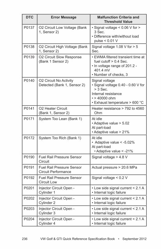
236 VW Golf & GTI Quick Reference Specification Book • September 2012
DTC Error Message Malfunction Criteria and Threshold Value
P0137 O2 Circuit Low Voltage (Bank 1, Sensor 2)
• Signal voltage < 0.06 V for > 3 Sec.
• Difference with/without load pulse < 0.01 V
P0138 O2 Circuit High Voltage (Bank 1, Sensor 2)
Signal voltage 1.08 V for > 5 Sec.
P0139 O2 Circuit Slow Response (Bank 1 Sensor 2)
• EWMA filtered transient time at fuel cutoff > 0.4 Sec.
• In voltage range of 201.2 - 401.4 mV
• Number of checks, 3P0140 O2 Circuit No Activity
Detected (Bank 1, Sensor 2)Signal voltage• Signal voltage 0.40 - 0.60 V for
> 3 Sec.Internal resistance • > 40000 ohm• Exhaust temperature > 600 °C
P0141 O2 Heater Circuit (Bank 1, Sensor 2)
Heater resistance > 792 to 4560 Ohm
P0171 System Too Lean (Bank 1) At idle • Adaptive value > 5.02At part-load • Adaptive value > 21%
P0172 System Too Rich (Bank 1) At idle • Adaptive value < -5.02%At part-load
• Adaptive value < -21%P0190 Fuel Rail Pressure Sensor
CircuitSignal voltage > 4.8 V
P0191 Fuel Rail Pressure Sensor Circuit Performance
Actual pressure > 20.6 MPa
P0192 Fuel Rail Pressure Sensor Circuit Low
Signal voltage < 0.2 V
P0201 Injector Circuit Open - Cylinder 1
• Low side signal current < 2.1 A• Internal logic failure
P0202 Injector Circuit Open - Cylinder 2
• Low side signal current < 2.1 A• Internal logic failure
P0203 Injector Circuit Open - Cylinder 3
• Low side signal current < 2.1 A• Internal logic failure
P0204 Injector Circuit Open - Cylinder 4
• Low side signal current < 2.1 A• Internal logic failure
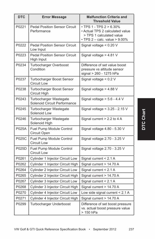
DTC
Cha
rt
VW Golf & GTI Quick Reference Specification Book • September 2012 237
DTC Error Message Malfunction Criteria and Threshold Value
P0221 Pedal Position Sensor Circuit Performance
• TPS 1 - TPS 2 > 6.30%• Actual TPS 2 calculated value
> TPS 1 calculated value• TPS 2 – calc. value > 9.00%
P0222 Pedal Position Sensor Circuit Low Input
Signal voltage < 0.20 V
P0223 Pedal Position Sensor Circuit High Input
Signal voltage > 4.81 V
P0234 Turbocharger Overboost Condition
Difference of set value boost pressure vs altitude sensor signal > 260 - 1275 hPa
P0237 Turbocharger Boost Sensor Circuit Low
Signal voltage < 0.2 V
P0238 Turbocharger Boost Sensor Circuit High
Signal voltage > 4.88 V
P0243 Turbocharger Wastegate Solenoid Circuit Performance
Signal voltage > 5.6 - 4.4 V
P0245 Turbocharger Wastegate Solenoid Low
Signal voltage < 3.25 - 2.15 V
P0246 Turbocharger Wastegate Solenoid High
Signal current > 2.2 to 4 A
P025A Fuel Pump Module Control Circuit Open
Signal voltage 4.80 - 5.30 V
P025C Fuel Pump Module Control Circuit Low
Signal voltage 2.70 - 3.25 V
P025D Fuel Pump Module Control Circuit Low
Signal voltage 2.70 - 3.25 V
P0261 Cylinder 1 Injector Circuit Low Signal current < 2.1 AP0262 Cylinder 1 Injector Circuit High Signal current > 14.70 AP0264 Cylinder 2 Injector Circuit Low Signal current < 2.1 AP0265 Cylinder 2 Injector Circuit High Signal current > 14.70 AP0267 Cylinder 3 Injector Circuit Low Signal current < 2.1 AP0268 Cylinder 3 Injector Circuit High Signal current > 14.70 AP0270 Cylinder 4 Injector Circuit Low Low side signal current < 2.1 AP0271 Cylinder 4 Injector Circuit High Signal current > 14.70 AP0299 Turbocharger Underboost Difference of set boost pressure
vs. actual boost pressure value > 150 hPa
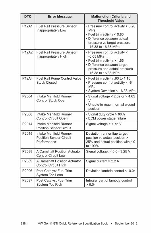
238 VW Golf & GTI Quick Reference Specification Book • September 2012
DTC Error Message Malfunction Criteria and Threshold Value
P12A1 Fuel Rail Pressure Sensor Inappropriately Low
• Pressure control activity > 0.20 MPa
• Fuel trim activity < 0.80• Difference between actual
pressure vs target pressure -16.38 to 16.38 MPa
P12A2 Fuel Rail Pressure Sensor Inappropriately High
• Pressure control activity < -0.05 MPa
• Fuel trim activity > 1.65• Difference between target
pressure and actual pressure -16.38 to 16.38 MPa
P12A4 Fuel Rail Pump Control Valve Stuck Closed
• Fuel trim activity .90 to 1.15• Pressure control activity < -6
MPa• System Deviation < 16.38 MPa
P2004 Intake Manifold Runner Control Stuck Open
• Signal voltage < 2.62 or > 4.65 V
• Unable to reach normal closed position
P2008 Intake Manifold Runner Control Circuit Open
• Signal duty cycle > 80%• ECM power stage failure
P2014 Intake Manifold Runner Position Sensor Circuit
Signal voltage > 4.75 V
P2015 Intake Manifold Runner Position Sensor Circuit Performance
Deviation runner flap target position vs actual position > 25% and actual position within 0 to 100%
P2088 A Camshaft Position Actuator Control Circuit Low
Signal voltage, < 0.0 - 3.25 V
P2089 A Camshaft Position Actuator Control Circuit High
Signal current > 2.2 A
P2096 Post Catalyst Fuel Trim System Too Lean
Deviation lambda control < -0.04
P2097 Post Catalyst Fuel Trim System Too Rich
Integral part of lambda control > 0.04
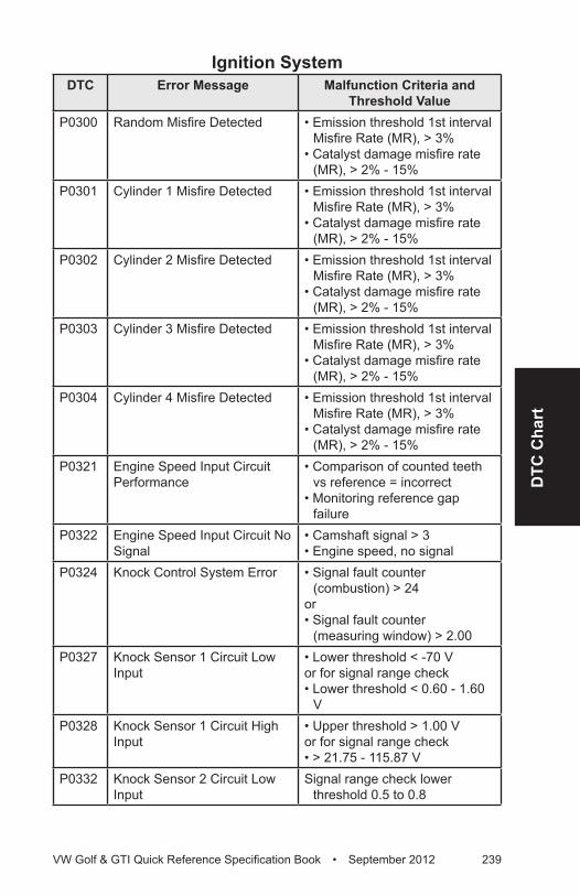
DTC
Cha
rt
VW Golf & GTI Quick Reference Specification Book • September 2012 239
Ignition SystemDTC Error Message Malfunction Criteria and
Threshold ValueP0300 Random Misfire Detected • Emission threshold 1st interval
Misfire Rate (MR), > 3% • Catalyst damage misfire rate
(MR), > 2% - 15% P0301 Cylinder 1 Misfire Detected • Emission threshold 1st interval
Misfire Rate (MR), > 3%• Catalyst damage misfire rate
(MR), > 2% - 15% P0302 Cylinder 2 Misfire Detected • Emission threshold 1st interval
Misfire Rate (MR), > 3%• Catalyst damage misfire rate
(MR), > 2% - 15% P0303 Cylinder 3 Misfire Detected • Emission threshold 1st interval
Misfire Rate (MR), > 3% • Catalyst damage misfire rate
(MR), > 2% - 15% P0304 Cylinder 4 Misfire Detected • Emission threshold 1st interval
Misfire Rate (MR), > 3% • Catalyst damage misfire rate
(MR), > 2% - 15% P0321 Engine Speed Input Circuit
Performance• Comparison of counted teeth
vs reference = incorrect• Monitoring reference gap
failureP0322 Engine Speed Input Circuit No
Signal• Camshaft signal > 3• Engine speed, no signal
P0324 Knock Control System Error • Signal fault counter (combustion) > 24
or • Signal fault counter
(measuring window) > 2.00P0327 Knock Sensor 1 Circuit Low
Input• Lower threshold < -70 V or for signal range check• Lower threshold < 0.60 - 1.60
VP0328 Knock Sensor 1 Circuit High
Input• Upper threshold > 1.00 Vor for signal range check • > 21.75 - 115.87 V
P0332 Knock Sensor 2 Circuit Low Input
Signal range check lower threshold 0.5 to 0.8
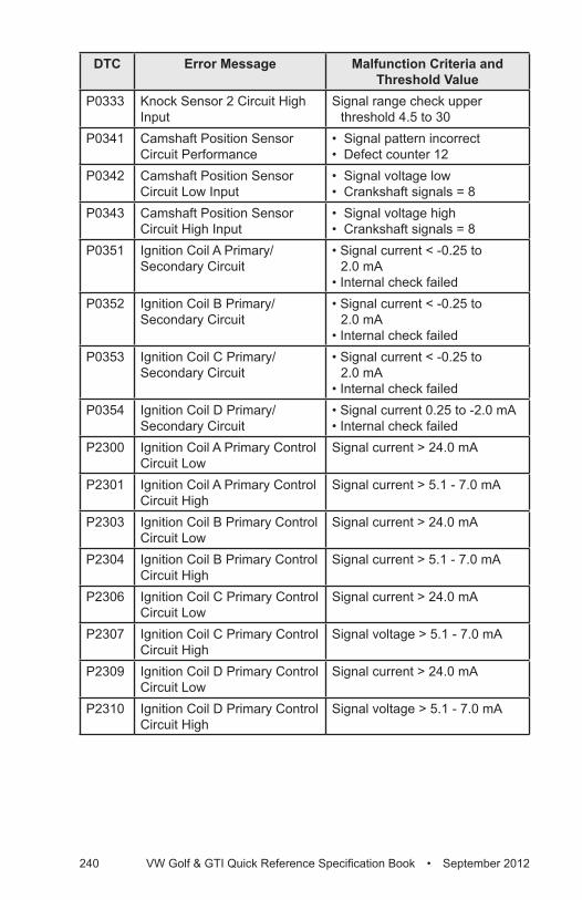
240 VW Golf & GTI Quick Reference Specification Book • September 2012
DTC Error Message Malfunction Criteria and Threshold Value
P0333 Knock Sensor 2 Circuit High Input
Signal range check upper threshold 4.5 to 30
P0341 Camshaft Position Sensor Circuit Performance
• Signal pattern incorrect• Defect counter 12
P0342 Camshaft Position Sensor Circuit Low Input
• Signal voltage low• Crankshaft signals = 8
P0343 Camshaft Position Sensor Circuit High Input
• Signal voltage high• Crankshaft signals = 8
P0351 Ignition Coil A Primary/Secondary Circuit
• Signal current < -0.25 to 2.0 mA
• Internal check failedP0352 Ignition Coil B Primary/
Secondary Circuit• Signal current < -0.25 to
2.0 mA• Internal check failed
P0353 Ignition Coil C Primary/Secondary Circuit
• Signal current < -0.25 to 2.0 mA
• Internal check failedP0354 Ignition Coil D Primary/
Secondary Circuit• Signal current 0.25 to -2.0 mA• Internal check failed
P2300 Ignition Coil A Primary Control Circuit Low
Signal current > 24.0 mA
P2301 Ignition Coil A Primary Control Circuit High
Signal current > 5.1 - 7.0 mA
P2303 Ignition Coil B Primary Control Circuit Low
Signal current > 24.0 mA
P2304 Ignition Coil B Primary Control Circuit High
Signal current > 5.1 - 7.0 mA
P2306 Ignition Coil C Primary Control Circuit Low
Signal current > 24.0 mA
P2307 Ignition Coil C Primary Control Circuit High
Signal voltage > 5.1 - 7.0 mA
P2309 Ignition Coil D Primary Control Circuit Low
Signal current > 24.0 mA
P2310 Ignition Coil D Primary Control Circuit High
Signal voltage > 5.1 - 7.0 mA
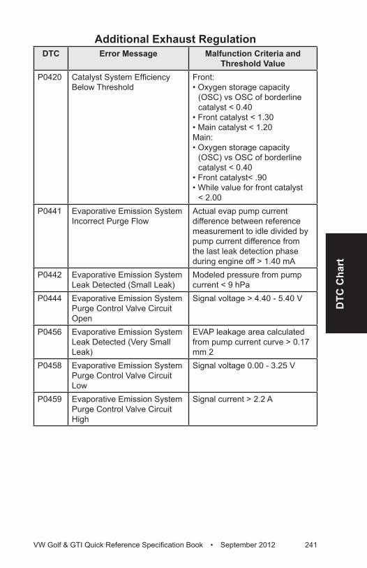
DTC
Cha
rt
VW Golf & GTI Quick Reference Specification Book • September 2012 241
Additional Exhaust RegulationDTC Error Message Malfunction Criteria and
Threshold ValueP0420 Catalyst System Efficiency
Below ThresholdFront: • Oxygen storage capacity
(OSC) vs OSC of borderline catalyst < 0.40
• Front catalyst < 1.30• Main catalyst < 1.20Main: • Oxygen storage capacity
(OSC) vs OSC of borderline catalyst < 0.40
• Front catalyst< .90• While value for front catalyst
< 2.00P0441 Evaporative Emission System
Incorrect Purge FlowActual evap pump current difference between reference measurement to idle divided by pump current difference from the last leak detection phase during engine off > 1.40 mA
P0442 Evaporative Emission System Leak Detected (Small Leak)
Modeled pressure from pump current < 9 hPa
P0444 Evaporative Emission System Purge Control Valve Circuit Open
Signal voltage > 4.40 - 5.40 V
P0456 Evaporative Emission System Leak Detected (Very Small Leak)
EVAP leakage area calculated from pump current curve > 0.17 mm 2
P0458 Evaporative Emission System Purge Control Valve Circuit Low
Signal voltage 0.00 - 3.25 V
P0459 Evaporative Emission System Purge Control Valve Circuit High
Signal current > 2.2 A
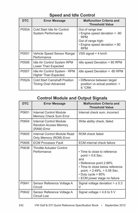
242 VW Golf & GTI Quick Reference Specification Book • September 2012
Speed and Idle ControlDTC Error Message Malfunction Criteria and
Threshold ValueP050A Cold Start Idle Air Control
System PerformanceOut of range low:• Engine speed deviation < -80
RPM Out of range high:• Engine speed deviation > 80
RPMP0501 Vehicle Speed Sensor Range/
PerformanceVSS signal < 4 km/h
P0506 Idle Air Control System RPM Lower Than Expected
Idle speed Deviation > 80 RPM
P0507 Idle Air Control System - RPM Higher Than Expected
Idle speed Deviation < -80 RPM
P052A Cold Start Camshaft Position Timing Over-Advanced
• Difference between target position vs actual position: > 6 °CRK
Control Module and Output SignalsDTC Error Message Malfunction Criteria and
Threshold ValueP0601 Internal Control Module
Memory Check Sum ErrorInternal check sum, incorrect
P0604 Internal Control Module Random Access Memory (RAM) Error
Write ability check, failed
P0605 Internal Control Module Read Only Memory (ROM) Error
ROM check failed
P0606 ECM Processor Fault ECM internal check failureP0638 Throttle Actuator Control
Performance • Time to close to reference point > 0.6 Sec.
and• Reference point 2.88%• Time to close below reference
point, + 2.49%, > 0.56 Sec.• Duty cycle > 80% • ECM power stage no failure
P0641 Sensor Reference Voltage A Circuit
Signal voltage deviation > ± 0.3 V
P0642 Sensor Reference Voltage A Circuit Low
Signal voltage < 4.6 to 5 V
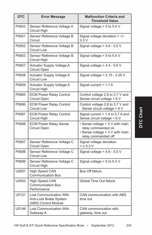
DTC
Cha
rt
VW Golf & GTI Quick Reference Specification Book • September 2012 243
DTC Error Message Malfunction Criteria and Threshold Value
P0643 Sensor Reference Voltage A Circuit High
Signal voltage > 5 to 5.4 V
P0651 Sensor Reference Voltage B Circuit
Signal voltage deviation > +/- 0.3 V
P0652 Sensor Reference Voltage B Circuit Low
Signal voltage < 4.6 - 5.0 V
P0653 Sensor Reference Voltage B Circuit High
Signal voltage > 5 to 5.4 V
P0657 Actuator Supply Voltage A Circuit Open
Signal voltage > 4.4 - 5.6 V
P0658 Actuator Supply Voltage A Circuit Low
Signal voltage < 2.15 - 3.25 V
P0659 Actuator Supply Voltage A Circuit High
Signal current > 1.1 A
P0685 ECM Power Relay Control Circuit Open
Control voltage 2.6 to 3.7 V and Sense circuit voltage < 6 V
P0686 ECM Power Relay Control Circuit Low
Control voltage 2.6 to 3.7 V and Sense circuit voltage > 6 V
P0687 ECM Power Relay Control Circuit High
Signal current > 1.4 to 0.7 A and Sense circuit voltage < 6 V
P0688 ECM Power Relay Sense Circuit Open
• Sense voltage > 3 V with main relay commanded on
• Sense voltage < 3 V with main relay commanded off
P0697 Sensor Reference Voltage C Circuit Open
Signal voltage deviation > ± 0.3 V
P0698 Sensor Reference Voltage C Circuit Low
Signal voltage < 4.6 - 5.0 V
P0699 Sensor Reference Voltage C Circuit High
Signal voltage > 5 to 5.4 V
U0001 High Speed CAN Communication Bus
Bus Off failure
U0002 High Speed CAN Communication Bus Performance
Global Time Out failure
U0121 Lost Communication With Anti-Lock Brake System (ABS) Control Module
CAN communication with ABS, time out
U0146 Lost Communication With Gateway A
CAN communication with gateway, time out
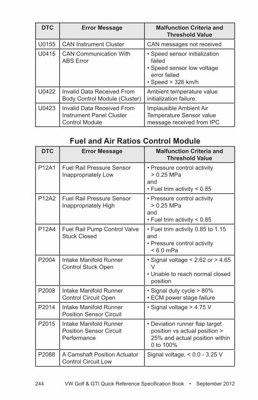
244 VW Golf & GTI Quick Reference Specification Book • September 2012
DTC Error Message Malfunction Criteria and Threshold Value
U0155 CAN Instrument Cluster CAN messages not receivedU0415 CAN Communication With
ABS Error• Speed sensor initialization
failed• Speed sensor low voltage
error failed• Speed > 326 km/h
U0422 Invalid Data Received From Body Control Module (Cluster)
Ambient temperature value initialization failure.
U0423 Invalid Data Received From Instrument Panel Cluster Control Module
Implausible Ambient Air Temperature Sensor value message received from IPC
Fuel and Air Ratios Control ModuleDTC Error Message Malfunction Criteria and
Threshold ValueP12A1 Fuel Rail Pressure Sensor
Inappropriately Low• Pressure control activity
> 0.25 MPaand• Fuel trim activity < 0.85
P12A2 Fuel Rail Pressure Sensor Inappropriately High
• Pressure control activity > 0.25 MPa
and• Fuel trim activity < 0.85
P12A4 Fuel Rail Pump Control Valve Stuck Closed
• Fuel trim activity 0.85 to 1.15and• Pressure control activity
< 6.0 mPaP2004 Intake Manifold Runner
Control Stuck Open• Signal voltage < 2.62 or > 4.65
V• Unable to reach normal closed
positionP2008 Intake Manifold Runner
Control Circuit Open• Signal duty cycle > 80%• ECM power stage failure
P2014 Intake Manifold Runner Position Sensor Circuit
• Signal voltage > 4.75 V
P2015 Intake Manifold Runner Position Sensor Circuit Performance
• Deviation runner flap target position vs actual position > 25% and actual position within 0 to 100%
P2088 A Camshaft Position Actuator Control Circuit Low
Signal voltage, < 0.0 - 3.25 V
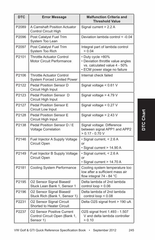
DTC
Cha
rt
VW Golf & GTI Quick Reference Specification Book • September 2012 245
DTC Error Message Malfunction Criteria and Threshold Value
P2089 A Camshaft Position Actuator Control Circuit High
Signal current > 2.2 A
P2096 Post Catalyst Fuel Trim System Too Lean
Deviation lambda control < -0.04
P2097 Post Catalyst Fuel Trim System Too Rich
Integral part of lambda control > 0.04
P2101 Throttle Actuator Control Motor Circuit Performance
• Duty cycle >80%• Deviation throttle value angles
vs. calculated value 4 - 50%• ECM power stage no failure
P2106 Throttle Actuator Control System Forced Limited Power
Internal check failed
P2122 Pedal Position Sensor D Circuit High Input
Signal voltage < 0.61 V
P2123 Pedal Position Sensor D Circuit High Input
Signal voltage > 4.79 V
P2127 Pedal Position Sensor E Circuit Low Input
Signal voltage < 0.27 V
P2128 Pedal Position Sensor E Circuit High Input
Signal voltage > 2.43 V
P2138 Pedal Position Sensor D / E Voltage Correlation
Signal voltage: Difference between signal APP1 and APP2 > 0.17 - 0.70 V
P2146 Fuel Injector A Supply Voltage Circuit Open
• Signal current, < 2.6 Aor • Signal current > 14.90 A
P2149 Fuel Injector B Supply Voltage Circuit Open
• Signal current, < 2.6 Aor • Signal current > 14.70 A
P2181 Cooling System Performance Cooling system temperature too low after a sufficient mass air flow integral 74 - 84 °C
P2195 O2 Sensor Signal Biased/Stuck Lean Bank 1, Sensor 1
Delta lambda of 2nd lambda control loop > 0.06
P2196 O2 Sensor Signal Biased/Stuck Rich (Bank 1, Sensor 1)
Delta lambda of 2nd lambda control loop < 0.08
P2231 O2 Sensor Signal Circuit Shorted to Heater Circuit
Delta O2S signal front > 190 uA
P2237 O2 Sensor Positive Current Control Circuit Open (Bank 1, Sensor 1)
O2S signal front 1.493 - 1.507 V and delta lambda controller > 0.10
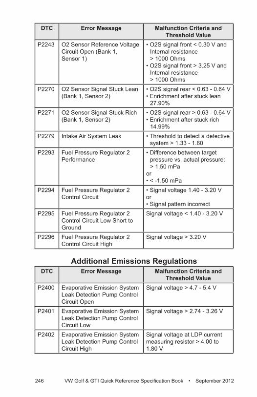
246 VW Golf & GTI Quick Reference Specification Book • September 2012
DTC Error Message Malfunction Criteria and Threshold Value
P2243 O2 Sensor Reference Voltage Circuit Open (Bank 1, Sensor 1)
• O2S signal front < 0.30 V and Internal resistance > 1000 Ohms
• O2S signal front > 3.25 V and Internal resistance > 1000 Ohms
P2270 O2 Sensor Signal Stuck Lean (Bank 1, Sensor 2)
• O2S signal rear < 0.63 - 0.64 V• Enrichment after stuck lean
27.90%P2271 O2 Sensor Signal Stuck Rich
(Bank 1, Sensor 2)• O2S signal rear > 0.63 - 0.64 V• Enrichment after stuck rich
14.99%P2279 Intake Air System Leak • Threshold to detect a defective
system > 1.33 - 1.60P2293 Fuel Pressure Regulator 2
Performance• Difference between target
pressure vs. actual pressure: > 1.50 mPa
or• < -1.50 mPa
P2294 Fuel Pressure Regulator 2 Control Circuit
• Signal voltage 1.40 - 3.20 Vor• Signal pattern incorrect
P2295 Fuel Pressure Regulator 2 Control Circuit Low Short to Ground
Signal voltage < 1.40 - 3.20 V
P2296 Fuel Pressure Regulator 2 Control Circuit High
Signal voltage > 3.20 V
Additional Emissions RegulationsDTC Error Message Malfunction Criteria and
Threshold ValueP2400 Evaporative Emission System
Leak Detection Pump Control Circuit Open
Signal voltage > 4.7 - 5.4 V
P2401 Evaporative Emission System Leak Detection Pump Control Circuit Low
Signal voltage > 2.74 - 3.26 V
P2402 Evaporative Emission System Leak Detection Pump Control Circuit High
Signal voltage at LDP current measuring resistor > 4.00 to 1.80 V
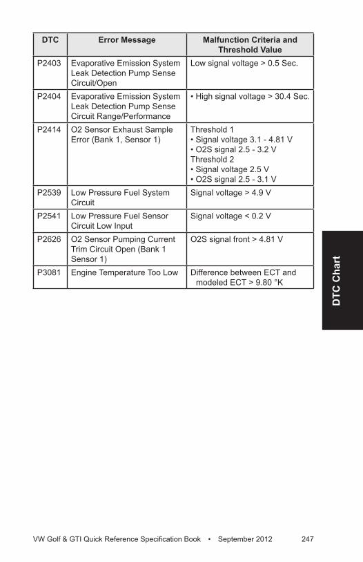
DTC
Cha
rt
VW Golf & GTI Quick Reference Specification Book • September 2012 247
DTC Error Message Malfunction Criteria and Threshold Value
P2403 Evaporative Emission System Leak Detection Pump Sense Circuit/Open
Low signal voltage > 0.5 Sec.
P2404 Evaporative Emission System Leak Detection Pump Sense Circuit Range/Performance
• High signal voltage > 30.4 Sec.
P2414 O2 Sensor Exhaust Sample Error (Bank 1, Sensor 1)
Threshold 1• Signal voltage 3.1 - 4.81 V• O2S signal 2.5 - 3.2 VThreshold 2• Signal voltage 2.5 V• O2S signal 2.5 - 3.1 V
P2539 Low Pressure Fuel System Circuit
Signal voltage > 4.9 V
P2541 Low Pressure Fuel Sensor Circuit Low Input
Signal voltage < 0.2 V
P2626 O2 Sensor Pumping Current Trim Circuit Open (Bank 1 Sensor 1)
O2S signal front > 4.81 V
P3081 Engine Temperature Too Low Difference between ECT and modeled ECT > 9.80 °K
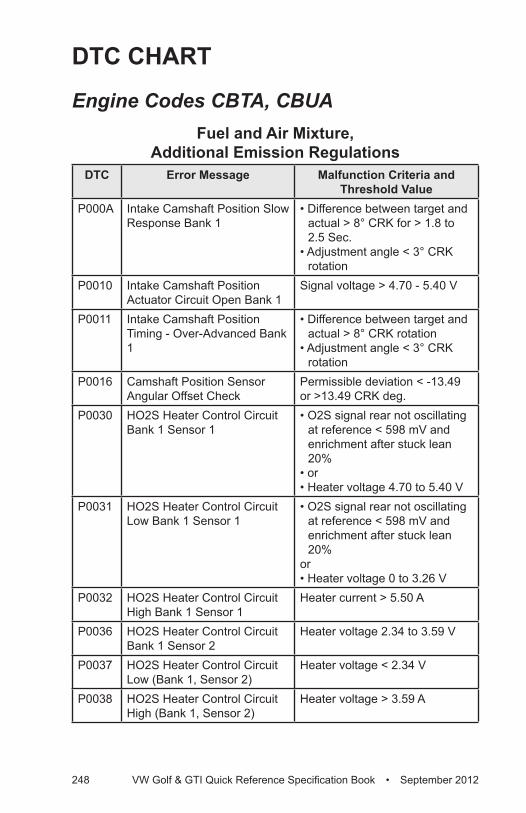
248 VW Golf & GTI Quick Reference Specification Book • September 2012
DTC CHART
Engine Codes CBTA, CBUAFuel and Air Mixture,
Additional Emission RegulationsDTC Error Message Malfunction Criteria and
Threshold ValueP000A Intake Camshaft Position Slow
Response Bank 1• Difference between target and
actual > 8° CRK for > 1.8 to 2.5 Sec.
• Adjustment angle < 3° CRK rotation
P0010 Intake Camshaft Position Actuator Circuit Open Bank 1
Signal voltage > 4.70 - 5.40 V
P0011 Intake Camshaft Position Timing - Over-Advanced Bank 1
• Difference between target and actual > 8° CRK rotation
• Adjustment angle < 3° CRK rotation
P0016 Camshaft Position Sensor Angular Offset Check
Permissible deviation < -13.49 or >13.49 CRK deg.
P0030 HO2S Heater Control Circuit Bank 1 Sensor 1
• O2S signal rear not oscillating at reference < 598 mV and enrichment after stuck lean 20%
• or• Heater voltage 4.70 to 5.40 V
P0031 HO2S Heater Control Circuit Low Bank 1 Sensor 1
• O2S signal rear not oscillating at reference < 598 mV and enrichment after stuck lean 20%
or• Heater voltage 0 to 3.26 V
P0032 HO2S Heater Control Circuit High Bank 1 Sensor 1
Heater current > 5.50 A
P0036 HO2S Heater Control Circuit Bank 1 Sensor 2
Heater voltage 2.34 to 3.59 V
P0037 HO2S Heater Control Circuit Low (Bank 1, Sensor 2)
Heater voltage < 2.34 V
P0038 HO2S Heater Control Circuit High (Bank 1, Sensor 2)
Heater voltage > 3.59 A
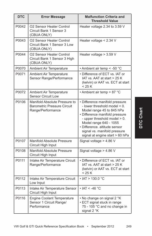
DTC
Cha
rt
VW Golf & GTI Quick Reference Specification Book • September 2012 249
DTC Error Message Malfunction Criteria and Threshold Value
P0042 O2 Sensor Heater Control Circuit Bank 1 Sensor 3 (CBUA ONLY)
Heater voltage 2.34 to 3.59 V
P0043 O2 Sensor Heater Control Circuit Bank 1 Sensor 3 Low (CBUA ONLY)
Heater voltage < 2.34 V
P0044 O2 Sensor Heater Control Circuit Bank 1 Sensor 3 High (CBUA ONLY)
Heater voltage > 3.59 V
P0070 Ambient Air Temperature • Ambient air temp < -50 °CP0071 Ambient Air Temperature
Sensor Range/Performance• Difference of ECT vs. IAT or
IAT vs. AAT at start > 25 K (kelvin) or AAT vs. ECT at start < 25 K
P0072 Ambient Air Temperature Sensor Circuit Low
• Ambient air temp > 87 °C
P0106 Manifold Absolute Pressure to Barometric Pressure Circuit Range/Performance
• Difference manifold pressure - lower threshold model < 0. Model range 45 to 845 hPa
• Difference manifold pressure - upper threshold model > 0. Model range 640 - 1055
• Difference. altitude sensor signal vs. manifold pressure signal at engine start > 60 hPa
P0107 Manifold Absolute Pressure Circuit High Input
Signal voltage > 4.86 V
P0108 Manifold Absolute Pressure Circuit High Input
Signal voltage > 4.86 V
P0111 Intake Air Temperature Circuit Range/Performance
• Difference of ECT vs. IAT or IAT vs. AAT at start > 25 K (kelvin) or AAT vs. ECT at start < 25 K
P0112 Intake Air Temperature Circuit Low Input
• IAT > 130.0 °C
P0113 Intake Air Temperature Sensor Circuit High Input
• IAT < -46 °C
P0116 Engine Coolant Temperature Sensor 1 Circuit Range/Performance
• No change on signal 2 °K• ECT signal stuck in range
75 - 105 °C and no change in signal 2 °K
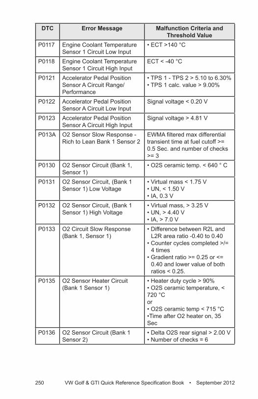
250 VW Golf & GTI Quick Reference Specification Book • September 2012
DTC Error Message Malfunction Criteria and Threshold Value
P0117 Engine Coolant Temperature Sensor 1 Circuit Low Input
• ECT >140 °C
P0118 Engine Coolant Temperature Sensor 1 Circuit High Input
ECT < -40 °C
P0121 Accelerator Pedal Position Sensor A Circuit Range/Performance
• TPS 1 - TPS 2 > 5.10 to 6.30% • TPS 1 calc. value > 9.00%
P0122 Accelerator Pedal Position Sensor A Circuit Low Input
Signal voltage < 0.20 V
P0123 Accelerator Pedal Position Sensor A Circuit High Input
Signal voltage > 4.81 V
P013A O2 Sensor Slow Response - Rich to Lean Bank 1 Sensor 2
EWMA filtered max differential transient time at fuel cutoff >= 0.5 Sec. and number of checks >= 3
P0130 O2 Sensor Circuit (Bank 1, Sensor 1)
• O2S ceramic temp. < 640 ° C
P0131 O2 Sensor Circuit, (Bank 1 Sensor 1) Low Voltage
• Virtual mass < 1.75 V• UN, < 1.50 V• IA, 0.3 V
P0132 O2 Sensor Circuit, (Bank 1 Sensor 1) High Voltage
• Virtual mass, > 3.25 V• UN, > 4.40 V• IA, > 7.0 V
P0133 O2 Circuit Slow Response (Bank 1, Sensor 1)
• Difference between R2L and L2R area ratio -0.40 to 0.40
• Counter cycles completed >/= 4 times
• Gradient ratio >= 0.25 or <= 0.40 and lower value of both ratios < 0.25.
P0135 O2 Sensor Heater Circuit (Bank 1 Sensor 1)
• Heater duty cycle > 90%• O2S ceramic temperature, < 720 °Cor• O2S ceramic temp < 715 °C•Time after O2 heater on, 35 Sec
P0136 O2 Sensor Circuit (Bank 1 Sensor 2)
• Delta O2S rear signal > 2.00 V• Number of checks = 6
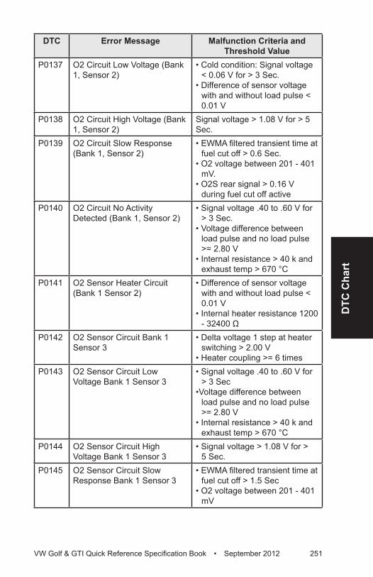
DTC
Cha
rt
VW Golf & GTI Quick Reference Specification Book • September 2012 251
DTC Error Message Malfunction Criteria and Threshold Value
P0137 O2 Circuit Low Voltage (Bank 1, Sensor 2)
• Cold condition: Signal voltage < 0.06 V for > 3 Sec.
• Difference of sensor voltage with and without load pulse < 0.01 V
P0138 O2 Circuit High Voltage (Bank 1, Sensor 2)
Signal voltage > 1.08 V for > 5 Sec.
P0139 O2 Circuit Slow Response (Bank 1, Sensor 2)
• EWMA filtered transient time at fuel cut off > 0.6 Sec.
• O2 voltage between 201 - 401 mV.
• O2S rear signal > 0.16 V during fuel cut off active
P0140 O2 Circuit No Activity Detected (Bank 1, Sensor 2)
• Signal voltage .40 to .60 V for > 3 Sec.
• Voltage difference between load pulse and no load pulse >= 2.80 V
• Internal resistance > 40 k and exhaust temp > 670 °C
P0141 O2 Sensor Heater Circuit (Bank 1 Sensor 2)
• Difference of sensor voltage with and without load pulse < 0.01 V
• Internal heater resistance 1200 - 32400 Ω
P0142 O2 Sensor Circuit Bank 1 Sensor 3
• Delta voltage 1 step at heater switching > 2.00 V
• Heater coupling >= 6 timesP0143 O2 Sensor Circuit Low
Voltage Bank 1 Sensor 3• Signal voltage .40 to .60 V for
> 3 Sec•Voltage difference between
load pulse and no load pulse >= 2.80 V
• Internal resistance > 40 k and exhaust temp > 670 °C
P0144 O2 Sensor Circuit High Voltage Bank 1 Sensor 3
• Signal voltage > 1.08 V for > 5 Sec.
P0145 O2 Sensor Circuit Slow Response Bank 1 Sensor 3
• EWMA filtered transient time at fuel cut off > 1.5 Sec
• O2 voltage between 201 - 401 mV
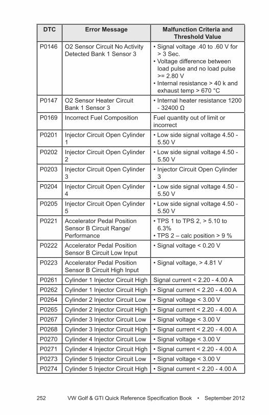
252 VW Golf & GTI Quick Reference Specification Book • September 2012
DTC Error Message Malfunction Criteria and Threshold Value
P0146 O2 Sensor Circuit No Activity Detected Bank 1 Sensor 3
• Signal voltage .40 to .60 V for > 3 Sec.
• Voltage difference between load pulse and no load pulse >= 2.80 V
• Internal resistance > 40 k and exhaust temp > 670 °C
P0147 O2 Sensor Heater Circuit Bank 1 Sensor 3
• Internal heater resistance 1200 - 32400 Ω
P0169 Incorrect Fuel Composition Fuel quantity out of limit or incorrect
P0201 Injector Circuit Open Cylinder 1
• Low side signal voltage 4.50 - 5.50 V
P0202 Injector Circuit Open Cylinder 2
• Low side signal voltage 4.50 - 5.50 V
P0203 Injector Circuit Open Cylinder 3
• Injector Circuit Open Cylinder 3
P0204 Injector Circuit Open Cylinder 4
• Low side signal voltage 4.50 - 5.50 V
P0205 Injector Circuit Open Cylinder 5
• Low side signal voltage 4.50 - 5.50 V
P0221 Accelerator Pedal Position Sensor B Circuit Range/Performance
• TPS 1 to TPS 2, > 5.10 to 6.3%
• TPS 2 – calc position > 9 %P0222 Accelerator Pedal Position
Sensor B Circuit Low Input• Signal voltage < 0.20 V
P0223 Accelerator Pedal Position Sensor B Circuit High Input
• Signal voltage, > 4.81 V
P0261 Cylinder 1 Injector Circuit High Signal current < 2.20 - 4.00 AP0262 Cylinder 1 Injector Circuit High • Signal current < 2.20 - 4.00 AP0264 Cylinder 2 Injector Circuit Low • Signal voltage < 3.00 VP0265 Cylinder 2 Injector Circuit High • Signal current < 2.20 - 4.00 AP0267 Cylinder 3 Injector Circuit Low • Signal voltage < 3.00 VP0268 Cylinder 3 Injector Circuit High • Signal current < 2.20 - 4.00 AP0270 Cylinder 4 Injector Circuit Low • Signal voltage < 3.00 VP0271 Cylinder 4 Injector Circuit High • Signal current < 2.20 - 4.00 AP0273 Cylinder 5 Injector Circuit Low • Signal voltage < 3.00 VP0274 Cylinder 5 Injector Circuit High • Signal current < 2.20 - 4.00 A
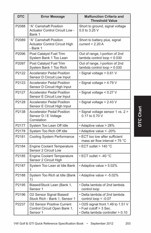
DTC
Cha
rt
VW Golf & GTI Quick Reference Specification Book • September 2012 253
DTC Error Message Malfunction Criteria and Threshold Value
P2088 “A” Camshaft Position Actuator Control Circuit Low - Bank 1
Short to ground, signal voltage 0.0 to 3.25 V
P2089 “A” Camshaft Position Actuator Control Circuit High - Bank 1
Short to battery plus, signal current > 2.20 A
P2096 Post Catalyst Fuel Trim System Bank 1 Too Lean
Out of range, I-portion of 2nd lambda control loop < 0.030
P2097 Post Catalyst Fuel Trim System Bank 1 Too Rich
Out of range, I-portion of 2nd lambda control loop > 0.030
P2122 Accelerator Pedal Position Sensor D Circuit Low Input
• Signal voltage < 0.61 V
P2123 Accelerator Pedal Position Sensor D Circuit High Input
• Signal voltage > 4.79 V
P2127 Accelerator Pedal Position Sensor E Circuit Low Input
• Signal voltage < 0.27 V
P2128 Accelerator Pedal Position Sensor E Circuit High Input
• Signal voltage > 2.43 V
P2138 Accelerator Pedal Position Sensor D / E Voltage Correlation
• Signal voltage sensor 1 vs. 2 > 0.17 to 0.70 V
P2177 System Too Lean Off Idle • Adaptive value > 28%P2178 System Too Rich Off Idle • Adaptive value < -20%P2181 Cooling System Performance • ECT too low after sufficient
mass air flow interval = 75 °CP2184 Engine Coolant Temperature
Sensor 2 Circuit Low• ECT outlet > 140 °C
P2185 Engine Coolant Temperature Sensor 2 Circuit High
• ECT outlet < -40 °C
P2187 System Too Lean at Idle Bank 1
• Adaptive value > 5.02%
P2188 System Too Rich at Idle (Bank 1)
• Adaptive value < -5.02%
P2195 Biased/Stuck Lean (Bank 1, Sensor 1
• Delta lambda of 2nd lambda control loop
P2196 O2 Sensor Signal Biased/Stuck Rich - Bank 1, Sensor 1
• Delta lambda of 2nd lambda control loop < -0.07
P2237 O2 Sensor Positive Current Control Circuit Open Bank 1, Sensor 1
• O2S signal front 1.49 to 1.51 V• Fuel cutoff > 3 Sec.• Delta lambda controller > 0.10
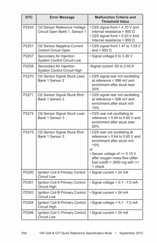
254 VW Golf & GTI Quick Reference Specification Book • September 2012
DTC Error Message Malfunction Criteria and Threshold Value
P2243 O2 Sensor Reference Voltage Circuit Open Bank 1, Sensor 1
• O2S signal front > 4.70 V and Internal resistance > 950 Ω
• O2S signal front < 0.20 V And Internal resistance > 950 Ω
P2251 O2 Sensor Negative Current Control Circuit Open
• O2S signal front 1.47 to 1.53 V and > 950 Ω
P2257 Secondary Air Injection System Control Circuit Low
• Signal voltage 0 to 3.26 V
P2258 Secondary Air Injection System Control Circuit High
•Signal current .60 to 2.40 A
P2270 O2 Sensor Signal Stuck Lean Bank 1 Sensor 2
• O2S signal rear not oscillating at reference < 598 mV and enrichment after stuck lean 20%
P2271 O2 Sensor Signal Stuck Rich Bank 1 Sensor 2
• O2S signal rear not oscillating at reference > 598 mV and enrichment after stuck rich 15%
P2274 O2 Sensor Signal Stuck Lean Bank 1 Sensor 3
• O2S rear not oscillating at reference < 0.64 to 0.65 V and enrichment after stuck lean 20%
P2275 O2 Sensor Signal Stuck Rich Bank 1 Sensor 3
• O2S rear not oscillating at reference > 0.64 to 0.65 V and enrichment after stuck rich 15%
or • Sensor voltage of >= 0.15 V
after oxygen mass flow (after fuel cutoff) > 3500 mg with >= 1 check
P2300 Ignition Coil A Primary Control Circuit Low
• Signal current > 24 mA
P2301 Ignition Coil A Primary Control Circuit High
• Signal voltage > 5.1 - 7.0 mA
P2303 Ignition Coil B Primary Control Circuit Low
• Signal current > 24 mA
P2304 Ignition Coil B Primary Control Circuit High
• Signal voltage > 5.1 - 7.0 mA
P2306 Ignition Coil C Primary Control Circuit Low
• Signal current > 24 mA
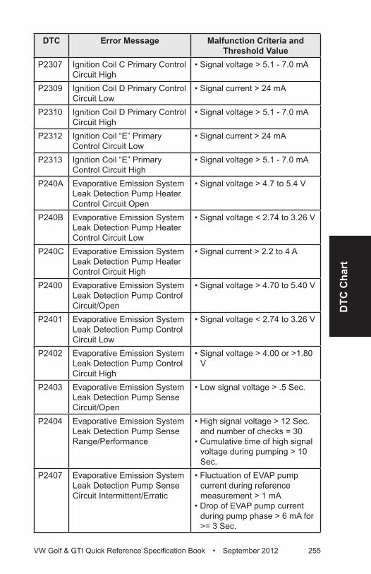
DTC
Cha
rt
VW Golf & GTI Quick Reference Specification Book • September 2012 255
DTC Error Message Malfunction Criteria and Threshold Value
P2307 Ignition Coil C Primary Control Circuit High
• Signal voltage > 5.1 - 7.0 mA
P2309 Ignition Coil D Primary Control Circuit Low
• Signal current > 24 mA
P2310 Ignition Coil D Primary Control Circuit High
• Signal voltage > 5.1 - 7.0 mA
P2312 Ignition Coil “E” Primary Control Circuit Low
• Signal current > 24 mA
P2313 Ignition Coil “E” Primary Control Circuit High
• Signal voltage > 5.1 - 7.0 mA
P240A Evaporative Emission System Leak Detection Pump Heater Control Circuit Open
• Signal voltage > 4.7 to 5.4 V
P240B Evaporative Emission System Leak Detection Pump Heater Control Circuit Low
• Signal voltage < 2.74 to 3.26 V
P240C Evaporative Emission System Leak Detection Pump Heater Control Circuit High
• Signal current > 2.2 to 4 A
P2400 Evaporative Emission System Leak Detection Pump Control Circuit/Open
• Signal voltage > 4.70 to 5.40 V
P2401 Evaporative Emission System Leak Detection Pump Control Circuit Low
• Signal voltage < 2.74 to 3.26 V
P2402 Evaporative Emission System Leak Detection Pump Control Circuit High
• Signal voltage > 4.00 or >1.80 V
P2403 Evaporative Emission System Leak Detection Pump Sense Circuit/Open
• Low signal voltage > .5 Sec.
P2404 Evaporative Emission System Leak Detection Pump Sense Range/Performance
• High signal voltage > 12 Sec. and number of checks = 30
• Cumulative time of high signal voltage during pumping > 10 Sec.
P2407 Evaporative Emission System Leak Detection Pump Sense Circuit Intermittent/Erratic
• Fluctuation of EVAP pump current during reference measurement > 1 mA
• Drop of EVAP pump current during pump phase > 6 mA for >= 3 Sec.
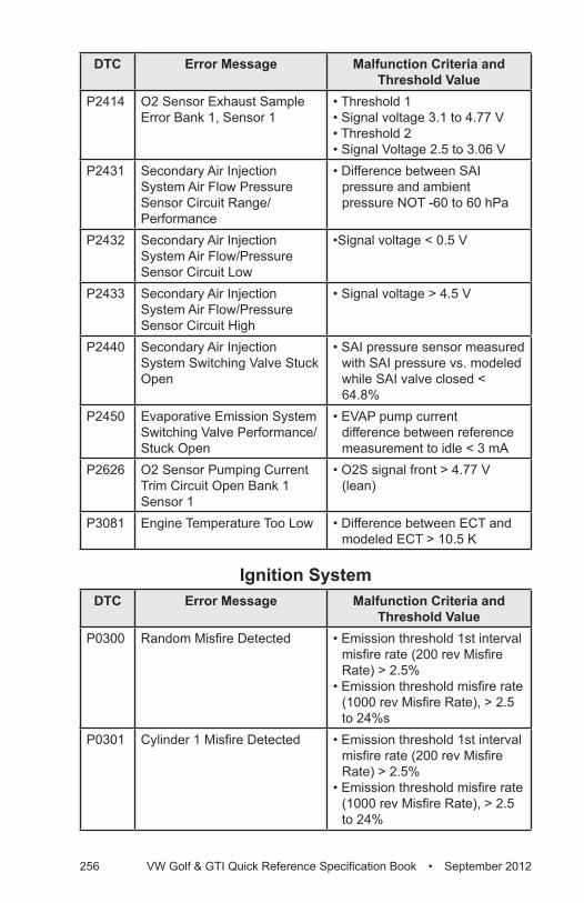
256 VW Golf & GTI Quick Reference Specification Book • September 2012
DTC Error Message Malfunction Criteria and Threshold Value
P2414 O2 Sensor Exhaust Sample Error Bank 1, Sensor 1
• Threshold 1• Signal voltage 3.1 to 4.77 V• Threshold 2• Signal Voltage 2.5 to 3.06 V
P2431 Secondary Air Injection System Air Flow Pressure Sensor Circuit Range/Performance
• Difference between SAI pressure and ambient pressure NOT -60 to 60 hPa
P2432 Secondary Air Injection System Air Flow/Pressure Sensor Circuit Low
•Signal voltage < 0.5 V
P2433 Secondary Air Injection System Air Flow/Pressure Sensor Circuit High
• Signal voltage > 4.5 V
P2440 Secondary Air Injection System Switching Valve Stuck Open
• SAI pressure sensor measured with SAI pressure vs. modeled while SAI valve closed < 64.8%
P2450 Evaporative Emission System Switching Valve Performance/Stuck Open
• EVAP pump current difference between reference measurement to idle < 3 mA
P2626 O2 Sensor Pumping Current Trim Circuit Open Bank 1 Sensor 1
• O2S signal front > 4.77 V (lean)
P3081 Engine Temperature Too Low • Difference between ECT and modeled ECT > 10.5 K
Ignition SystemDTC Error Message Malfunction Criteria and
Threshold ValueP0300 Random Misfire Detected • Emission threshold 1st interval
misfire rate (200 rev Misfire Rate) > 2.5%
• Emission threshold misfire rate (1000 rev Misfire Rate), > 2.5 to 24%s
P0301 Cylinder 1 Misfire Detected • Emission threshold 1st interval misfire rate (200 rev Misfire Rate) > 2.5%
• Emission threshold misfire rate (1000 rev Misfire Rate), > 2.5 to 24%
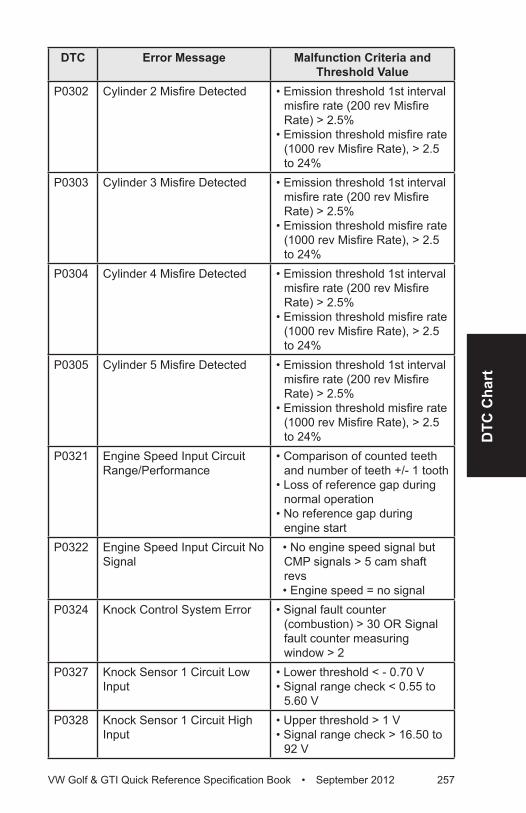
DTC
Cha
rt
VW Golf & GTI Quick Reference Specification Book • September 2012 257
DTC Error Message Malfunction Criteria and Threshold Value
P0302 Cylinder 2 Misfire Detected • Emission threshold 1st interval misfire rate (200 rev Misfire Rate) > 2.5%
• Emission threshold misfire rate (1000 rev Misfire Rate), > 2.5 to 24%
P0303 Cylinder 3 Misfire Detected • Emission threshold 1st interval misfire rate (200 rev Misfire Rate) > 2.5%
• Emission threshold misfire rate (1000 rev Misfire Rate), > 2.5 to 24%
P0304 Cylinder 4 Misfire Detected • Emission threshold 1st interval misfire rate (200 rev Misfire Rate) > 2.5%
• Emission threshold misfire rate (1000 rev Misfire Rate), > 2.5 to 24%
P0305 Cylinder 5 Misfire Detected • Emission threshold 1st interval misfire rate (200 rev Misfire Rate) > 2.5%
• Emission threshold misfire rate (1000 rev Misfire Rate), > 2.5 to 24%
P0321 Engine Speed Input Circuit Range/Performance
• Comparison of counted teeth and number of teeth +/- 1 tooth
• Loss of reference gap during normal operation
• No reference gap during engine start
P0322 Engine Speed Input Circuit No Signal
• No engine speed signal but CMP signals > 5 cam shaft revs
• Engine speed = no signal P0324 Knock Control System Error • Signal fault counter
(combustion) > 30 OR Signal fault counter measuring window > 2
P0327 Knock Sensor 1 Circuit Low Input
• Lower threshold < - 0.70 V• Signal range check < 0.55 to
5.60 VP0328 Knock Sensor 1 Circuit High
Input• Upper threshold > 1 V • Signal range check > 16.50 to
92 V
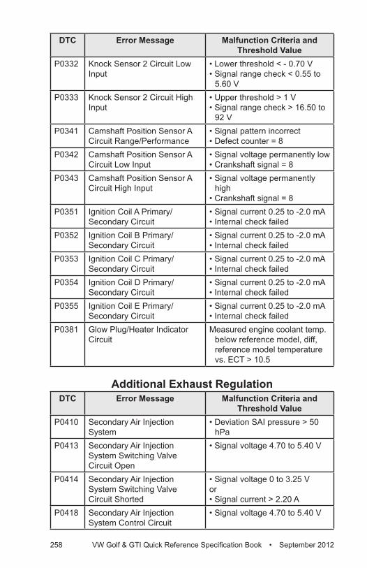
258 VW Golf & GTI Quick Reference Specification Book • September 2012
DTC Error Message Malfunction Criteria and Threshold Value
P0332 Knock Sensor 2 Circuit Low Input
• Lower threshold < - 0.70 V• Signal range check < 0.55 to
5.60 VP0333 Knock Sensor 2 Circuit High
Input• Upper threshold > 1 V• Signal range check > 16.50 to
92 VP0341 Camshaft Position Sensor A
Circuit Range/Performance• Signal pattern incorrect• Defect counter = 8
P0342 Camshaft Position Sensor A Circuit Low Input
• Signal voltage permanently low• Crankshaft signal = 8
P0343 Camshaft Position Sensor A Circuit High Input
• Signal voltage permanently high
• Crankshaft signal = 8P0351 Ignition Coil A Primary/
Secondary Circuit• Signal current 0.25 to -2.0 mA• Internal check failed
P0352 Ignition Coil B Primary/Secondary Circuit
• Signal current 0.25 to -2.0 mA• Internal check failed
P0353 Ignition Coil C Primary/Secondary Circuit
• Signal current 0.25 to -2.0 mA• Internal check failed
P0354 Ignition Coil D Primary/Secondary Circuit
• Signal current 0.25 to -2.0 mA• Internal check failed
P0355 Ignition Coil E Primary/Secondary Circuit
• Signal current 0.25 to -2.0 mA• Internal check failed
P0381 Glow Plug/Heater Indicator Circuit
Measured engine coolant temp. below reference model, diff, reference model temperature vs. ECT > 10.5
Additional Exhaust RegulationDTC Error Message Malfunction Criteria and
Threshold ValueP0410 Secondary Air Injection
System• Deviation SAI pressure > 50
hPaP0413 Secondary Air Injection
System Switching Valve Circuit Open
• Signal voltage 4.70 to 5.40 V
P0414 Secondary Air Injection System Switching Valve Circuit Shorted
• Signal voltage 0 to 3.25 Vor• Signal current > 2.20 A
P0418 Secondary Air Injection System Control Circuit
• Signal voltage 4.70 to 5.40 V
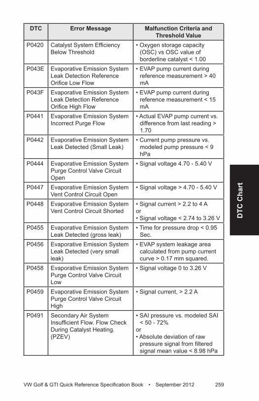
DTC
Cha
rt
VW Golf & GTI Quick Reference Specification Book • September 2012 259
DTC Error Message Malfunction Criteria and Threshold Value
P0420 Catalyst System Efficiency Below Threshold
• Oxygen storage capacity (OSC) vs OSC value of borderline catalyst < 1.00
P043E Evaporative Emission System Leak Detection Reference Orifice Low Flow
• EVAP pump current during reference measurement > 40 mA
P043F Evaporative Emission System Leak Detection Reference Orifice High Flow
• EVAP pump current during reference measurement < 15 mA
P0441 Evaporative Emission System Incorrect Purge Flow
• Actual EVAP pump current vs. difference from last reading > 1.70
P0442 Evaporative Emission System Leak Detected (Small Leak)
• Current pump pressure vs. modeled pump pressure < 9 hPa
P0444 Evaporative Emission System Purge Control Valve Circuit Open
• Signal voltage 4.70 - 5.40 V
P0447 Evaporative Emission System Vent Control Circuit Open
• Signal voltage > 4.70 - 5.40 V
P0448 Evaporative Emission System Vent Control Circuit Shorted
• Signal current > 2.2 to 4 A or• Signal voltage < 2.74 to 3.26 V
P0455 Evaporative Emission System Leak Detected (gross leak)
• Time for pressure drop < 0.95 Sec.
P0456 Evaporative Emission System Leak Detected (very small leak)
• EVAP system leakage area calculated from pump current curve > 0.17 mm squared.
P0458 Evaporative Emission System Purge Control Valve Circuit Low
• Signal voltage 0 to 3.26 V
P0459 Evaporative Emission System Purge Control Valve Circuit High
• Signal current, > 2.2 A
P0491 Secondary Air System Insufficient Flow. Flow Check During Catalyst Heating. (PZEV)
• SAI pressure vs. modeled SAI < 50 - 72%
or• Absolute deviation of raw
pressure signal from filtered signal mean value < 8.98 hPa
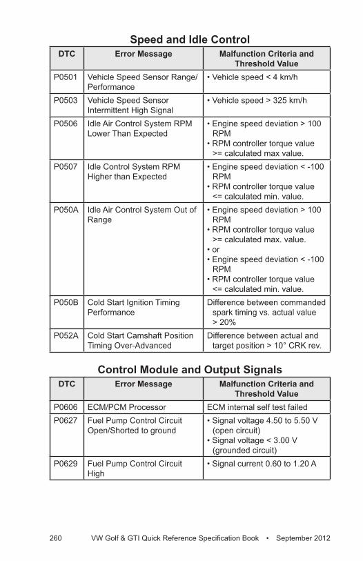
260 VW Golf & GTI Quick Reference Specification Book • September 2012
Speed and Idle ControlDTC Error Message Malfunction Criteria and
Threshold ValueP0501 Vehicle Speed Sensor Range/
Performance• Vehicle speed < 4 km/h
P0503 Vehicle Speed Sensor Intermittent High Signal
• Vehicle speed > 325 km/h
P0506 Idle Air Control System RPM Lower Than Expected
• Engine speed deviation > 100 RPM
• RPM controller torque value >= calculated max value.
P0507 Idle Control System RPM Higher than Expected
• Engine speed deviation < -100 RPM
• RPM controller torque value <= calculated min. value.
P050A Idle Air Control System Out of Range
• Engine speed deviation > 100 RPM
• RPM controller torque value >= calculated max. value.
• or• Engine speed deviation < -100
RPM • RPM controller torque value
<= calculated min. value.P050B Cold Start Ignition Timing
PerformanceDifference between commanded
spark timing vs. actual value > 20%
P052A Cold Start Camshaft Position Timing Over-Advanced
Difference between actual and target position > 10° CRK rev.
Control Module and Output SignalsDTC Error Message Malfunction Criteria and
Threshold ValueP0606 ECM/PCM Processor ECM internal self test failedP0627 Fuel Pump Control Circuit
Open/Shorted to ground• Signal voltage 4.50 to 5.50 V
(open circuit)• Signal voltage < 3.00 V
(grounded circuit)P0629 Fuel Pump Control Circuit
High• Signal current 0.60 to 1.20 A
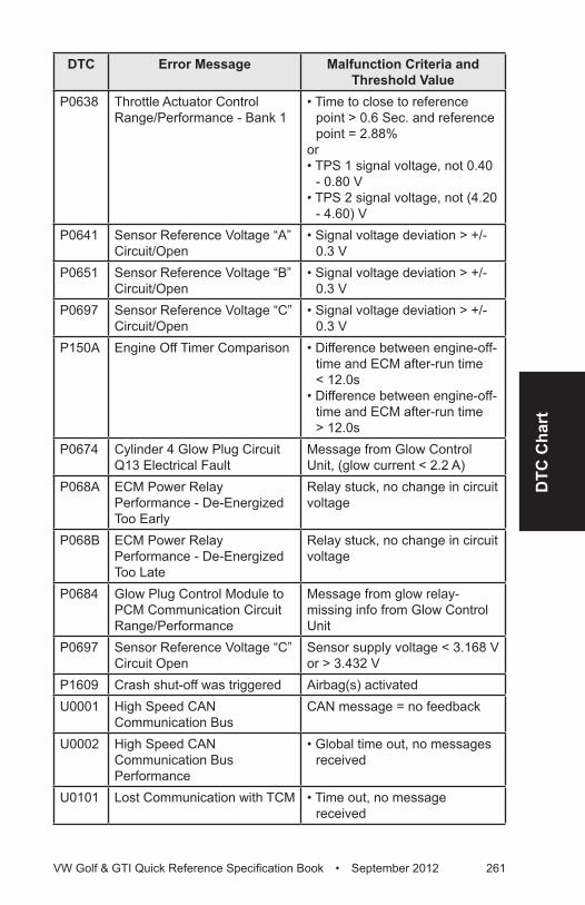
DTC
Cha
rt
VW Golf & GTI Quick Reference Specification Book • September 2012 261
DTC Error Message Malfunction Criteria and Threshold Value
P0638 Throttle Actuator Control Range/Performance - Bank 1
• Time to close to reference point > 0.6 Sec. and reference point = 2.88%
or• TPS 1 signal voltage, not 0.40
- 0.80 V• TPS 2 signal voltage, not (4.20
- 4.60) VP0641 Sensor Reference Voltage “A”
Circuit/Open• Signal voltage deviation > +/-
0.3 VP0651 Sensor Reference Voltage “B”
Circuit/Open• Signal voltage deviation > +/-
0.3 VP0697 Sensor Reference Voltage “C”
Circuit/Open• Signal voltage deviation > +/-
0.3 VP150A Engine Off Timer Comparison • Difference between engine-off-
time and ECM after-run time < 12.0s
• Difference between engine-off-time and ECM after-run time > 12.0s
P0674 Cylinder 4 Glow Plug Circuit Q13 Electrical Fault
Message from Glow Control Unit, (glow current < 2.2 A)
P068A ECM Power Relay Performance - De-Energized Too Early
Relay stuck, no change in circuit voltage
P068B ECM Power Relay Performance - De-Energized Too Late
Relay stuck, no change in circuit voltage
P0684 Glow Plug Control Module to PCM Communication Circuit Range/Performance
Message from glow relay- missing info from Glow Control Unit
P0697 Sensor Reference Voltage “C” Circuit Open
Sensor supply voltage < 3.168 V or > 3.432 V
P1609 Crash shut-off was triggered Airbag(s) activatedU0001 High Speed CAN
Communication BusCAN message = no feedback
U0002 High Speed CAN Communication Bus Performance
• Global time out, no messages received
U0101 Lost Communication with TCM • Time out, no message received
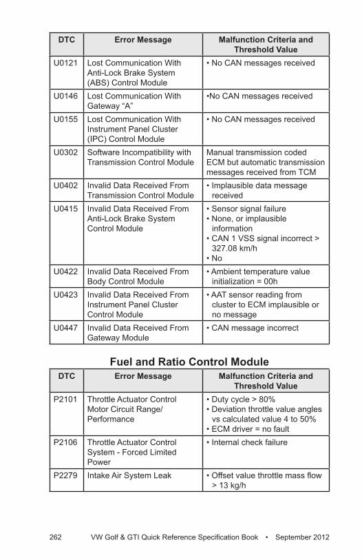
262 VW Golf & GTI Quick Reference Specification Book • September 2012
DTC Error Message Malfunction Criteria and Threshold Value
U0121 Lost Communication With Anti-Lock Brake System (ABS) Control Module
• No CAN messages received
U0146 Lost Communication With Gateway “A”
•No CAN messages received
U0155 Lost Communication With Instrument Panel Cluster (IPC) Control Module
• No CAN messages received
U0302 Software Incompatibility with Transmission Control Module
Manual transmission coded ECM but automatic transmission messages received from TCM
U0402 Invalid Data Received From Transmission Control Module
• Implausible data message received
U0415 Invalid Data Received From Anti-Lock Brake System Control Module
• Sensor signal failure• None, or implausible
information• CAN 1 VSS signal incorrect >
327.08 km/h• No
U0422 Invalid Data Received From Body Control Module
• Ambient temperature value initialization = 00h
U0423 Invalid Data Received From Instrument Panel Cluster Control Module
• AAT sensor reading from cluster to ECM implausible or no message
U0447 Invalid Data Received From Gateway Module
• CAN message incorrect
Fuel and Ratio Control ModuleDTC Error Message Malfunction Criteria and
Threshold ValueP2101 Throttle Actuator Control
Motor Circuit Range/Performance
• Duty cycle > 80%• Deviation throttle value angles
vs calculated value 4 to 50%• ECM driver = no fault
P2106 Throttle Actuator Control System - Forced Limited Power
• Internal check failure
P2279 Intake Air System Leak • Offset value throttle mass flow > 13 kg/h

Volkswagen Group of America works constantly to develop and improve its products. We must therefore reserve the right to change or update any part of this technical manual at any time. No legal commitment can therefore be derived from the information, illustrations or descriptions in this manual.
The texts, illustrations and standards in this manual are based on the information available at the time of printing. No part of this manual may be reprinted, reproduced or translated without the written permission of Volkswagen Group of America.
All rights under the copyright laws are expressly reserved by Volkswagen Group of America. Subject to alteration and amendment.
Printed in the United States of America © 2012 Volkswagen Group of America, Inc.

GFGTIQUSPEC13