2012 spim conference, 7 december 2012, london th … im...2012 spim conference, 7 december 2012,...
TRANSCRIPT

th
Update on SURF IM Joint Industry Project2012 SPIM Conference, 7th December 2012, London
Patrick O’BrienPatrick O Brien,Group Director Strategic Business & Marketing, Wood Group Kenny
Experience that Delivers

Introduction
Key Presentation Points:
• SURF IM Participation & Workscope
• Picture Tour of what is being doneg
• How SURF IM JIP is evolving for the future
1Experience that Delivers

SURF IM Joint Industry Projecty j
• Participation:– BG, BHP Billiton, BP, Chevron, Hess, Maersk Oil, Petrobras, Petronas, Shell,
Suncor Total WoodsideSuncor, Total, Woodside
• Scope:– Review of SURF System Design & Operation (An integrated approach)– Review of SURF System Design & Operation (An integrated approach)– Comprehensive Catalogue of Failures & Failure Mechanisms– Identify and catalogue existing inspection and monitoring technology
Evaluate Inspection & Monitoring Technology Gaps and identify emerging– Evaluate Inspection & Monitoring Technology Gaps and identify emerging appropriate technologies for SURF inspection & monitoring
– Prepare a Best-Practice Guidance Note for SURF Integrity Management
• Schedule– Commenced: January 2011– Complete: Mid 2013
2Experience that Delivers
– Complete: Mid 2013

SURF Integrity Management Guidelineg y g
Public DomainReview Relevant
Industry Standards
Operator Experiences
Best Practice SURF IMOperators’ Best Practices
Expertise in
Is sharing possible?
Mapping Failure Modes onto an
Wood Group Kenny
Experience
Expertise in Integrity
Management & Technology
Modes onto an Inspection &
Monitoring Strategy
3Experience that Delivers

SURF IM Work Scope (Graphically)( y)
Industry Experience
Design and Operational
Requirements
• Operational Experience• Design Experience• Failure Modes/Mechanisms
Failure Mechanisms
SURF IMJIP
Scope of WorkIndustry Integrity
Management
Holistic Integrity Management Methodology
Inspection and
pgApproach
InspectionMonitoring
Methodology
Requirements
pMonitoring
Requirements
Assessment ofInspection/
MonitoringSamplingTesting & Analysis
4Experience that Delivers
Inspection/ Condition
MonitoringMethods
Potential New Insp. and Monitoring Technologies

Assessment of Probability of Occurrence (as input to Risk)Occurrence (as input to Risk)
Probability UPP o yIndex, P ][ ADUTSOPP o
T h l St O tTechnology Step-Out:Uncertainty concerning new technology applications
Anomaly:Uncertainty due to anomaly or defect from construction, installation or operation.
Design Uncertainty :Uncertainty from • Inputs: design basis• Response: analytical p
techniques or tools
What we don’t knowwe don’t know
What we know we don’t know
What we know we know
Increase in P due to uncertainty
Po TSO DUwe know
1 2 3 4 5
uncertainty
Possible reduction in P due to IM measures reducing uncertainty
5Experience that Delivers
reducing uncertainty

SURF IM Evolution
• Physical and VC MeetingsPhysical and VC Meetings
• 3-Day Physical Meetings– Perth March 2011– Houston November 2011– Aberdeen and Oslo May 2012– London October 2012
P i M 2013– Paris May 2013
• Meetings take time (1.5 days) to share knowledge on subsea component failures and subsea operations experienceand subsea operations experience– Engage local operator offices as we move around
• SURF IM Scope Extension– Subsea Processing– SURF IM Business Case– Sharing Experience on Application of New Inspection & Monitoring
Techniques
6Experience that Delivers
Techniques

Develop / Review IM Performance Standards/ Processes
Corporate Requirements & Standard Risk Matrix
Regulatory Requirements Integrity Basis
PreparationOutput
Assemble / ReviewSystem Data
SystemSubdivision & Grouping
Design Data
F b/I t ll I ti d /
Previous IM Work (e.g. Risk analysis, IM Plans)
Failure Mode Database HAZIDHazard & Risk Analysis
Reporting / Documentation
Risk Analysis
Fab/Install, Inspection and / or Operational Data
RiskAssessment
All risks acceptable?
Implement Barriers / Mitigation Measures
Reliability Assessment
No
Yes
Failure Database
Develop Integrity Management Plan
Inspection Monitoring Analysis and Testing Operational Procedures Preventative Maintenance
Anomaly Limits / KPIs Anomaly Limits / KPIs Anomaly Limits / KPIs Anomaly Limits / KPIs Anomaly Limits / KPIs
Database of Available IM Measures
Integrity Management Plan
S St t
Implement Integrity Management Plan
Periodic Review & Fitness Assessment
Risk Assessment and / or IM Plan
RevisionInspection and / or Operational Data
Spares Strategy
Schedule
Plan executed?Review / Propose Revision of Neglected Procedures
Regulatory / Compliance Review(If Required) Fitness Statement &
Recommended Changes
Regulatory / Compliance
No
Yes
7Experience that DeliversFit for Purpose?Develop & Execute Repair /
Remediation Plan
g y pReports
(If Required)
No
Yes
Yes
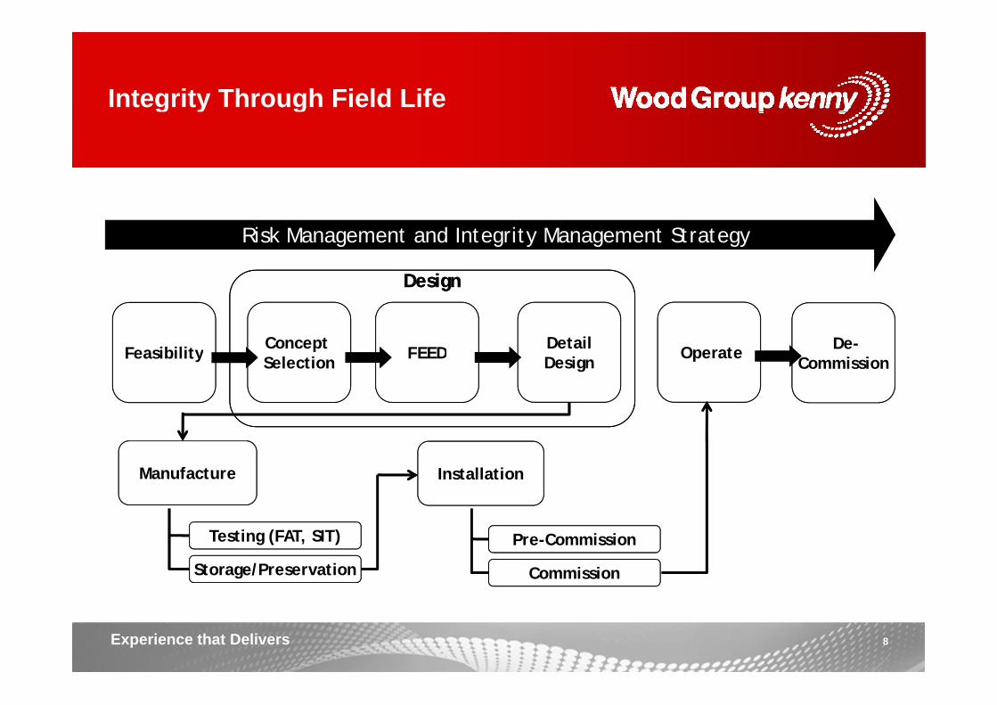
Integrity Through Field Lifeg y g
Risk Management and Integrity Management Strategy
FeasibilityFeasibility Concept Concept FEEDFEED DetailDetail OperateOperate De-De-
DesignDesign
FeasibilityFeasibility SelectionSelection FEEDFEED DesignDesign OperateOperateCommissionCommission
InstallationInstallationManufacture
Testing (FAT, SIT)
Storage/Preservation
Pre-Commission
Commission
8Experience that Delivers

Failure Modes Categorisationg
• Accidental Damage • Fatigue
Failure Drivers
• Corrosion/Erosion• Electrical;
• Flow Assurance/ Flow Restriction• Temperature
P• Pressure
9Experience that Delivers

Mapping Failure Modes to IM Strategyg gy
M f il d b id tifi ti f i ti b li dMap failure modes by identification of existing baseline and emerging technology:
Failu
re N
o.
Equipment Failure Consequence Integrity Management Measures
Equipment Sub- Failure Failure Initiator Mechanism Failure Record of O CS CE CC Monitoring Inspection Testing and Procedures MaintenanceF Equipment component Driver Mode Initiator Mechanism Result Occurrence CS CE CC Monitoring Inspection Analysis Procedures Maintenance
Subsea Piping - Jumpers, Flowlines and Spools
SP 0
01
Subsea Piping1. Jumpers2. Flowlines3. Spools en
tal D
amag
e
External damage collapse
or rupture
1. Dropped objects due to 3rd party2. Anchors and mooring vessels
3. Dragged line4. ROV impact
5. Natural disaster (iceberg
Deformation or over stress
due to localized oc
arbo
n co
ntai
nmen
t
Happened to
operator(s)NA M H 1. Pressure 1.GVI
1. Metal loss defect
assessment
1. Deck lifting and handling
2. Vessel exclusion zone
3. Dropped object
Acc
ide or rupture interaction, storm, etc)
6. Trawl board/fishing activityimpact
Loss
of H
ydro reporting
4. ROV handling
10Experience that Delivers

Technology Review Processgy
Failure Modes Assessment
(Task 1.0)
Baseline Inspection & Monitoring Measures
Baseline Technology Catalogue
Public Domain Identification of Emerging T h l i
TRL AssessmentReview Technologies
Operator Experiences
How is Integrity Assessed?
Technology Gaps
11Experience that Delivers

Baseline Inspection & Monitoring TechnologyTechnology
Compilation of Baseline Technology• Identification of technologies available to support baseline
Inspection & Monitoring MeasuresInspection & Monitoring Measures • Completion of catalogue with technologies available to be
deployed for assessment of specific defect or deterioration. • Classification based on Failure Drivers
– Facilitate mapping of technologies to failure mode assessmentassessment
– Systematic approach to ensurecomprehensive review
f– Presentation using a Flowchart format• Compilation of technology datasheets
12Experience that Delivers

Baseline Technology MappingElectrical Power / CommunicationsElectrical Power / Communications
13Experience that Delivers

Baseline Technology MappingErosion / Internal CorrosionErosion / Internal Corrosion
14Experience that Delivers

Technology Datasheets Compilationgy
Technology Datasheet CatalogueTechnology Datasheet – CatalogueMethod 1.3 Intelligent NDT Inspection Pigging
Magnetic Flux Leakage
Control Systems
Magnetic Flux LeakagePURPOSE
1 Applicable S t
To utilize magnetic fields to detect flaws and cracks in steel sections. MFL are currently used extensively in intellignet pigs as a NDT inspection technique
Subsea PipingSubsea Structures (main piping)UmbilicalsXmas TreeDDD : Defect, Detection and Degradation Monitoring2 Strategic Level
Systems
DDD : Defect, Detection and Degradation MonitoringELR : Exposure, Load and Response MonitoringSLM : Safety Limit MonitoringGLC : General Layout and Configuration MonitoringGlobal Integrity / Condition.3 Scope of
C diti
2 Strategic Level
Local Integrity / Condition.Exposure / Environment.
External.Internal.In-line
Condition Assessment
4 Level of Intrusion
15Experience that Delivers
In-line.
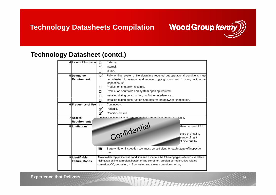
Technology Datasheets Compilationgy
T h l D t h t ( td )Technology Datasheet (contd.)External.Internal.In-line.Fully on line system No downtime required but operational conditions must
4 Level of Intrusion
5 Downtime Fully on-line system. No downtime required but operational conditions mustbe adjusted to release and receive pigging tools and to carry out actualinspection run.Production shutdown required.Production shutdown and system opening required.Installed during construction; no further interference.
5 Downtime Requirement
Installed during construction and requires shutdown for inspection.Continuous.Periodic.Condition based.
7 Access Pigging requires release trap, reception trap and assurance of wide ID
6 Frequency of Use
Requirements(i) Capable of detecting cracks wider than 0.1mm and longer than between 25 to
50mm. Pipe diameter range from 8 to 30inches(ii) Poor internal pipeline cleaning prior to inspection run, presence of small ID
valves or other components compared with pipeline ID, presence of tight bends tees or 90° elbows and out of roundness or ovality of pipe due to
valves/components and wide bends on pipeline system.
8 Limitations
bends, tees or 90 elbows and out of roundness or ovality of pipe due to shocks or blows, falling objects, etc.
(iii) Battery life on inspection tool must be sufficient for each stage of inspection run.
9 Identifiable Failure Modes
Allow to detect pipeline wall condition and ascertain the following types of corrosive attack: Pitting, top of line corrosion, bottom of line corrosion, erosion-corrosion, flow related corrosion CO corrosion H S corrosion and stress corrosion cracking
16Experience that Delivers
corrosion, CO2 corrosion, H2S corrosion and stress corrosion cracking.

Technology Datasheets Compilationsgy
T h l D t h t ( td )Technology Datasheet (contd.)Description of Method
The following equipment is relevant to intelligent pigging inspection:
MFL inspection: An electromagnetic testing technique; for this case the pigging tool is equipped with very powerful rare earth magnets and these in contact with the pipe wall create a magnetic field, which is stable and uniform if there are no indications. H if th i di ti t ( ll thi i ) th ti fi ld11 E i t
10
• Polyurethane cups pipeline cleaning pig.• Steel brushes/scrapers pipeline cleaning pig.• Chemicals/inhibitors flushing pig.• Dummy calibration pig.
The following equipment is relevant to intelligent pigging inspection:11 Equipment
• Fully instrumented (UT or MFL + recorder + battery pack) inspection pig.12 Preparation
RequirementsTo carry out intelligent pigging inspections delivery or release traps and reception traps must be available topside. Traps are ancillary items of pipeline equipment, with associated pipework and valves for introducing a pig into a pipeline or removing a pig from a pipeline. Usually for engineering design purposes, traps are considered p p y g g g p p , p"pipeline accessories" and thus trap barrels are designed according to ANSI B31.4 (Liquid pipelines) or ANSI B31.8 (Gas pipelines); quick opening trap end closures are designed according to ASME VIII, Div. 1. At traps locations lifting capabilities (permanent or temporary) are required to handle the heavy and long intelligent inspection pigs. Depending on the length of the pipeline several traps may be necessary, otherwise the pig's battery-pack charge may not last the complete run. In addition, careful coordination with Operations must be forthcoming to assure the appropriate pipeline flow conditions for optimum pig velocity.
13 Time Requirements
Pigging operations: Depend on length of pipeline being inspected and number of pigging traps in system.
17Experience that Delivers
(i) Scan rates of Pigs typically 0.2 to 4m/s.

Emerging Technologiesg g g
SURF IM Objectives• Industry survey of emerging technologyIndustry survey of emerging technology
• Identification of IM technology gaps and on-going technology development to address these gapsto address these gaps
• Sources include public domain, operator experience, vendor contacts
• Technologies are identified along with vendors, type of application and methodologygy
• For emerging technologies, the objective is to assign a Technology Readiness Level assessment based on API 17N
18Experience that Delivers
Readiness Level assessment based on API 17N

Emerging Technologiesg g g
Year C t l S b X Areas of Application Technology Company TRL reached TRL
Control Systems Flowline Jumper Subsea
Structures Umbilicals Xmas Trees
Intelligent Pigging -EMAT
RosenGE 5 2008 • •
Intelligent Pigging - R 2 2012Intelligent Pigging Eddy Current Rosen 2 2012 •
Ultrasonic Phased Array Sensor
GESensorlinkClampOn
5 2010 • •
WT Measurement
MagnetostrictiveSensor Guided Wave
Technology
SWRIGULTWITNO
5 2012 •
MFL & UT Pipeway 5 2011 • •& U pe ay 5 0
Digital Radiography VJ TechnologiesApplus RTD 5 2010 • •
Electric Field Mapping Sensors
Roxar Fox tek 7(1) 2007 • • •Sensors Fox-tek
Electrical Resistance Probes – Spool
Teledyne Cormon 6(2) 2008(2) • • •
Halfwave DNV 5 2012 • •Gamma Ray Tracerco 7/5(3) 2008 •
19Experience that Delivers
Transmission Survey Tracerco 7/5( ) 2008 •

Emerging Technologiesg g g
Year Areas of Application Technology Company TRL
Year reached
TRL
Control Systems Flowline Jumper Subsea
Structures Umbilicals Xmas Trees
Reson Aquadyne
SeaBat
Leak Detection
Sonar
SeaBat acoustics
Sonardyne WavefrontBlueview
Technologies
5 2012 • • • • • •
TechnologiesWeatherford
(Come Monday)Bio Sensor Biota Guard • • • •Fiber Optic
Measurement Schlumberger 5 2012 • • •Measurement g
Physical DamageAUV
Lockheed MartinUTEC
KongsbergC&C
Cybernetix 7(4) 2005 • • • • • •Physical Damage(CVI)
CybernetixTeledyne Gavia
AUVSeebyte
ECA
7(4) 2005 • • • • • •
Blockage Pulsed Pressure Paradigm 6(5) • • •
20Experience that Delivers
Blockage Pulsed Pressure Paradigm 6(5) • • •

Gaps & Recommendations
Gap analysis to identify areas that require additional development and provide aGap analysis to identify areas that require additional development and provide a road map to bridge the gaps between current status of technology and the desired performance specification.
Gap Recommendations
Uncertainties of internal corrosion and internal corrosion/erosion models. A study to baseline various corrosion models against volunteer member corrosion monitoring/ inspection results.
NB: Draft Only
Follow results from multiple corrosion/ erosion model JIP, such as University of Tulsa JIP, Ohio JIP, TOPCORP JIP and Deepstar findings from Alternative to ILI.
Standardized method/ process for chemical selection and performance verification
Develop a method /process to validate chemical effectiveness performance and dose optimization
Corrosion Management
verification. effectiveness performance, and dose optimization.Best practice on the design of flood water treatment: Chemical package design. Injection practices. Performance verification / monitoring through life of the flood.
Standard practices for the design of flood water treatment. JIP member organizations will all have internal practices that could be drawn together for mandatory minimum requirements and best practice g g y q precommendations.
Uncertainties with corrosion susceptibility of 316 clad steel when exposed to seawater (e.g.: if 316 clad when exposed to water begins to pit, does the pitting
Guidelines for the corrosion resistance of 316L to seawater / clad pipe based on depth/ temperature/ location.
21Experience that Delivers
cease if the seawater is removed and production conditions imposed).

Gaps & Recommendations
Gap Recommendations
Sand Management
Sand detection technology unreliable Yes/No in some instruments. Review the detectability limits of current sensors (especially acoustic), and
methods of quantifying sand
NB: Draft Only
Review Recommend Practice for sensor location.
Remote instrumentationIssue of power source/retrievable for battery replacement or alternative power source
Develop/investigate wireless acoustic instrumentation in subsea service. Either constantly transmitting ones (some systems use the pipeline as a “cable”), or passive systems that are interrogated by ROV on a periodic basis (physical dock or ireless transmission)
Condition Monitoring
or wireless transmission).
Online strain gauges A review of state-of-the-art and development of guideline of best practice and how long term reliability can be achieved.
Tools to predict degradation on control systems Review industry best practice and propose guideline.
Leak Detection
Time lag on detection of oil leaks. More efficient detection/ diagnostic techniques and remediation for oil leaks (Identification, localization, quantification and classification, as per Ref. 8)e.g. system should have the ability to detect x liters of oil coming from x drill Leak Detection g y y gcenter.
BlockageAbility to quantify % of lines that are plugged, location, length and characterization
A review of best practice and propose guideline. Technologies available should also be assessed to benchmark results.
22Experience that Delivers

Gaps & Recommendations
Gap Recommendations NB: Draft OnlyGap RecommendationsAlternative to ILI: Technology limited to coating. Removal of insulation. Accuracy for defect sizing.
Develop a ROV deployable system with the following specification: Good accuracy – the ability to provide WT data in ½-inch (12.7mm)
resolution pixels within 0.2 mm; Depth capable – the ability to go down to 11,000+ feet (3400m) of
NB: Draft Only
y g Marinization of tools. Issues with 360 deg access, for buried pipe. Source/Energy to subsea application. Pipe-in-pipe.
p p y g ( )water;
WT capable – the ability to inspect pipe walls up to 50 mm thick; Speed capable – the ability to inspect at typical ROV speeds of several
knots. Ability to detect through typical subsea pipeline and field joint coatings
Inspections
Ability to detect through typical subsea pipeline and field joint coatings, 3LPP, FBE, TSA, Shrink sleeves etc.
WT Inspection ILI Develop a ILI tool with the following specification: Small size – the ability to enter 6-inch lines and navigate through pipe
bends;G d b tt lif th bilit t i t 40 il i t 2 5 MPH (16 Good battery life – the ability to inspect a 40 mile pipe at 2.5 MPH (16 hours);
Good accuracy – the ability to provide 360º WT data in ½-inch (12.7mm) resolution pixels within 0.2 mm;
Depth capable – the ability to go down to 11,000+ feet of water; WT capable – the ability to inspect pipe walls up to 50 mm.
Cost effective inspection campaigns. Further develop AUV technology to perform close visual inspection.Reliability of corrosion monitoring spools. Develop guideline on how to improve long term reliability of subsea corrosion
monitoring spools.Better and reliable fatigue crack inspection tools ILI Further development of technology tools and algorithms to analyze results
23Experience that Delivers
Better and reliable fatigue crack inspection tools ILI type.
Further development of technology, tools and algorithms to analyze results.

Internal SURF IM Discussions
Typical Discussion Topics:
Real-time continuous monitoring system (corrosion)Real time continuous monitoring system (corrosion)
• Ultrasonic Phased Array Sensor– Vendors for this technology: GE (Rightrax), Sensorlink (Ultramonit) and
ClampOn (Corrosion Erosion Monitoring).
• Electrical field mapping technique:– Vendors for this technology: Roxar (CorrOcean) – Field Signature Method
(FSM) and Fox-tek – Pin-Point Electrical Field Mapping(FSM) and Fox tek Pin Point Electrical Field Mapping
• Magnetostrictive Sensor Guided Wave Technology:V d f thi t h l SWRI GUL TWI d TNO
24Experience that Delivers
– Vendors for this technology: SWRI, GUL, TWI and TNO.

Supplier Presentations to SURF IM
GE Oil d G• Lockheed Martin– AUV Inspection Technology
• Clamp-on
• GE Oil and Gas– Umbilical & Flexible Riser
Monitoring• Cameron
– Acoustic Sand Detection• Weatherford
– Leak Detection and others
• Cameron– Remote Subsea Infrasture
Condition Monitoring• AGR
• Applus RTD– Various metal inspection
technology
– Wall Thickness & Weld Inspection• Aker Solutions & Bornemann
– Subsea Pumping Technology• Viper Subsea
– V-SLIM Insulation Resistance Monitoring
• Framo– Condition Monitoring of Subsea
Pumps• Eagle Burgmann• Smart Fibres Ltd
– Optical Sensing Technology for Subsea Condition Monitoring
• Eagle Burgmann– Subsea Sealing Technology for
Pumps
25Experience that Delivers

AUV Technology for Inspectiongy
S L kh d M ti W b itSource: Lockheed Martin Website
Graphic: Surveying a Pipeline
L kh d M ti ’ M li AUVLockheed Martin’s Marlin AUV
• 3D High resolution optical and acoustic sensor package
26Experience that Delivers
g p p g
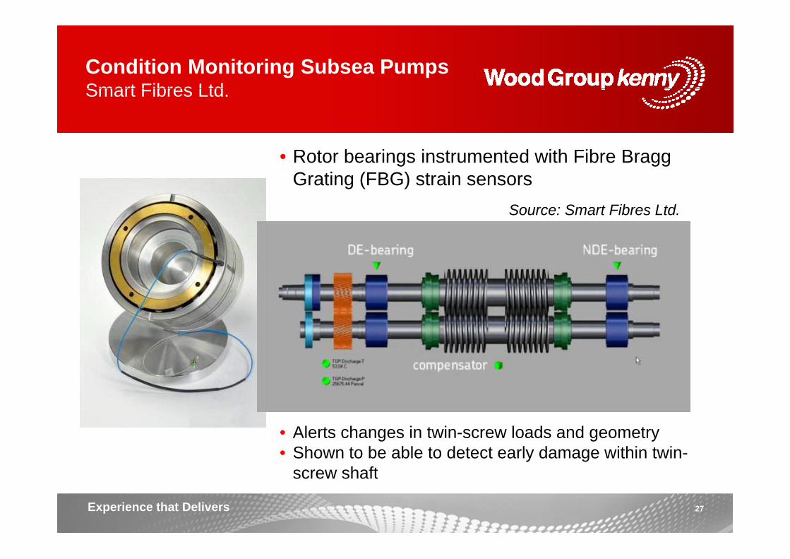
Condition Monitoring Subsea PumpsSmart Fibres LtdSmart Fibres Ltd.
R t b i i t t d ith Fib B
Source: Smart Fibres Ltd.
• Rotor bearings instrumented with Fibre Bragg Grating (FBG) strain sensors
• Alerts changes in twin-screw loads and geometry• Shown to be able to detect early damage within twin-
screw shaft
27Experience that Delivers
screw shaft

Future of SURF IM
Where do we go from here?• SURF IM will deliver it’s scope by mid 2013
• Phase 2 now in planning– SURF IM Forum– Specific Study ScopesSpecific Study Scopes– Other operators coming on board
• Effective engagement with supply chain and technology developers ofEffective engagement with supply chain and technology developers of inspection and condition monitoring technology
• Lever for ongoing technology developmentLever for ongoing technology development– Spawn off JIPs on collaborative technology qualification / trialing for a
range of specific inspection and monitoring techniques to close the technology gaps
28Experience that Delivers
gy g p

Thank you
A ti ?Any questions?
Experience that Delivers