2009 facility rehabilitation june 2008 - pub · 2009 facility rehabilitation june 2008 ......
TRANSCRIPT
1.1 2009 Faciliry Rehabilitation NP 2009 CBA
2009 Facility Rehabilitation
June 2008
Prepared by:
Gary K. Hmby, P.Eng.
1.1 2009 Facility Rehabilitation NP 2009 CBA
i
Table of Contents
Page 1.0 Introduction..........................................................................................................................1
2.0 Horsechops Protection, Control and Governor Refurbishment ...........................................1 3.0 Hydro Dam Rehabilitation...................................................................................................4
4.0 Generation Equipment Replacements Due to In-Service Failures ......................................6 5.0 Update Plant Metering .........................................................................................................7 6.0 Engineering For Seal Cove Runner Replacement ...............................................................7 7.0 Recommendation .................................................................................................................8
1.1 2009 Facility Rehabilitation NP 2009 CBA
1
1.0 Introduction The 2009 Facility Rehabilitation project is necessary for the replacement or rehabilitation of deteriorated plant components that have been identified through routine inspections, operating experience and engineering studies. The project includes expenditures necessary to improve the efficiency and reliability of various hydro plants or to replace plant due to in-service failures. The Company has 23 hydroelectric plants that provide energy to the Island Interconnected System. Maintaining these generating facilities reduces the need for additional, more expensive, generation. Items involving replacement and rehabilitation work, which are identified during inspections and maintenance activities, are necessary to the continued operation of these generation facilities in a safe, reliable and environmentally compliant manner. The Company’s hydro generation facilities produce a combined normal annual production of 425.8 GWh1. The alternative to maintaining these facilities would be to retire them. The 2009 Facility Rehabilitation project totalling $1,917,000 is comprised of Horsechops Protection, Control and Governor Refurbishment; Hydro Dam Rehabilitation; Generation Equipment Replacements Due to In-Service Failures; Upgrade Plant Revenue Metering; and, Engineering for Seal Cove Runner Replacement. 2.0 Horsechops Protection, Control and Governor Refurbishment
Cost: $947,000
The Horsechops generating plant was commissioned in 1954 and has a nameplate rating of 8.3 MW. The normal annual production from the plant is 43.0 GWhr or approximately 10.1% of Newfoundland Power’s annual hydroelectric production. The plant contains a vertical 10,000 hp Francis turbine manufactured by Dominion Engineering and a Canadian General Electric generator. The unit is automated and controlled remotely through the SCADA system. The plant is connected to the Island Interconnected System at Mobile substation via Newfoundland Power’s transmission line 20L. Major work completed at this facility in recent years includes the installation of a steel surge tank, steel penstock and intake structure and new main inlet valve. The existing protection and control schemes, including the governor, generator protection, voltage regulation and plant control system are obsolete and are in need of modernization.
1 Normal annual production was established as 419.6 GWh in the Water Management Study – Hydrology Update
prepared by SGE Acres dated August 1, 2005. Normal production was increased by 6.2 GWh as a result of the capacity increase at Rattling Brook to make the revised base normal hydroelectric production to be 425.8 GWh.
1.1 2009 Facility Rehabilitation NP 2009 CBA
2
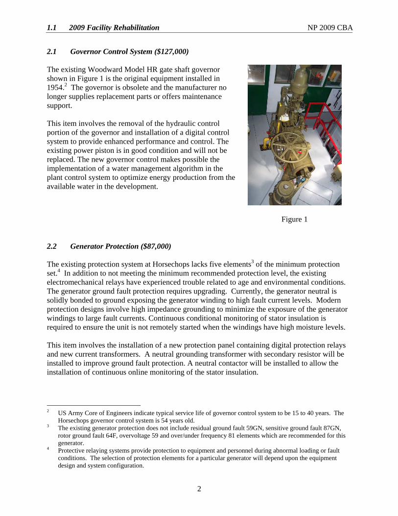
2.1 Governor Control System ($127,000) The existing Woodward Model HR gate shaft governor shown in Figure 1 is the original equipment installed in 1954.2 The governor is obsolete and the manufacturer no longer supplies replacement parts or offers maintenance support. This item involves the removal of the hydraulic control portion of the governor and installation of a digital control system to provide enhanced performance and control. The existing power piston is in good condition and will not be replaced. The new governor control makes possible the implementation of a water management algorithm in the plant control system to optimize energy production from the available water in the development.
Figure 1
2.2 Generator Protection ($87,000) The existing protection system at Horsechops lacks five elements3 of the minimum protection set.4 In addition to not meeting the minimum recommended protection level, the existing electromechanical relays have experienced trouble related to age and environmental conditions. The generator ground fault protection requires upgrading. Currently, the generator neutral is solidly bonded to ground exposing the generator winding to high fault current levels. Modern protection designs involve high impedance grounding to minimize the exposure of the generator windings to large fault currents. Continuous conditional monitoring of stator insulation is required to ensure the unit is not remotely started when the windings have high moisture levels. This item involves the installation of a new protection panel containing digital protection relays and new current transformers. A neutral grounding transformer with secondary resistor will be installed to improve ground fault protection. A neutral contactor will be installed to allow the installation of continuous online monitoring of the stator insulation.
2 US Army Core of Engineers indicate typical service life of governor control system to be 15 to 40 years. The
Horsechops governor control system is 54 years old. 3 The existing generator protection does not include residual ground fault 59GN, sensitive ground fault 87GN,
rotor ground fault 64F, overvoltage 59 and over/under frequency 81 elements which are recommended for this generator.
4 Protective relaying systems provide protection to equipment and personnel during abnormal loading or fault conditions. The selection of protection elements for a particular generator will depend upon the equipment design and system configuration.
1.1 2009 Facility Rehabilitation NP 2009 CBA
3
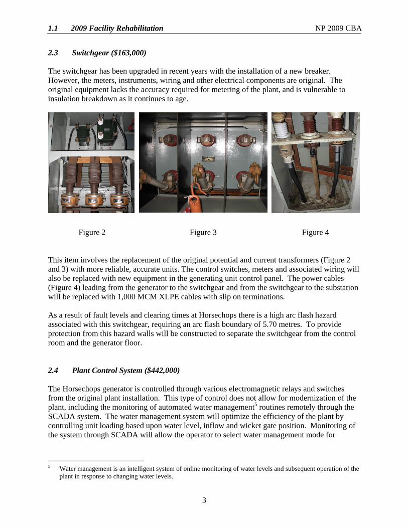
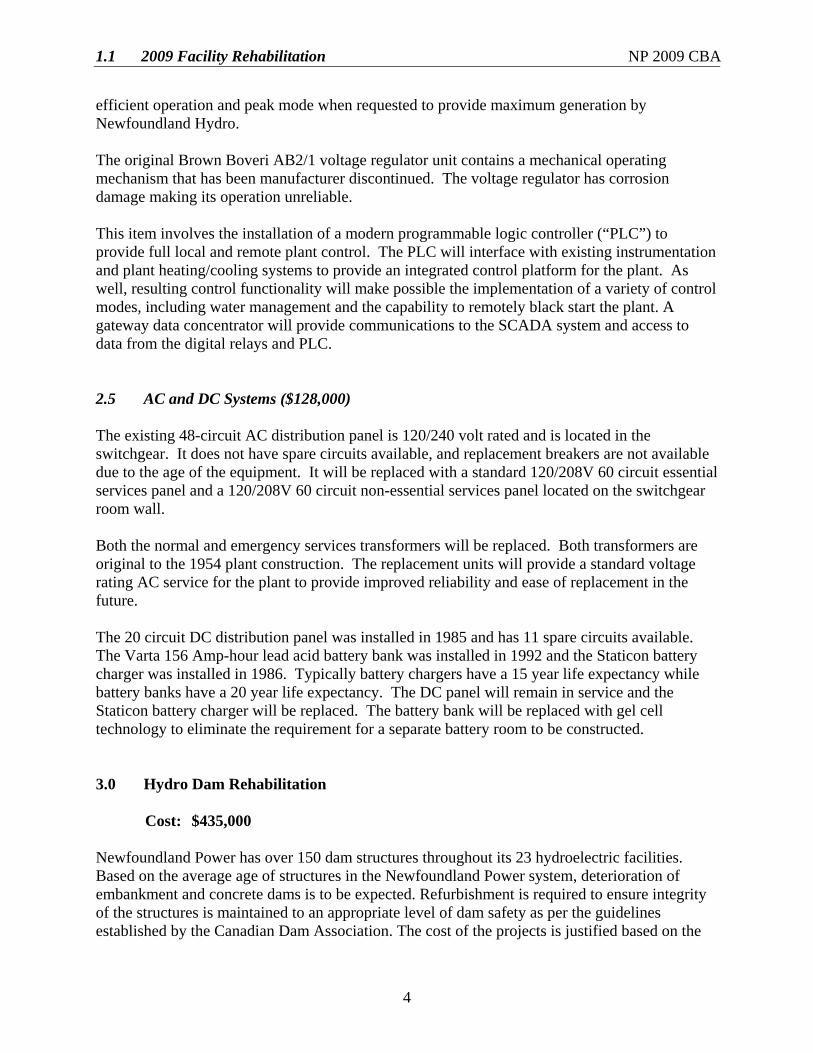
2.3 Switchgear ($163,000) The switchgear has been upgraded in recent years with the installation of a new breaker. However, the meters, instruments, wiring and other electrical components are original. The original equipment lacks the accuracy required for metering of the plant, and is vulnerable to insulation breakdown as it continues to age.
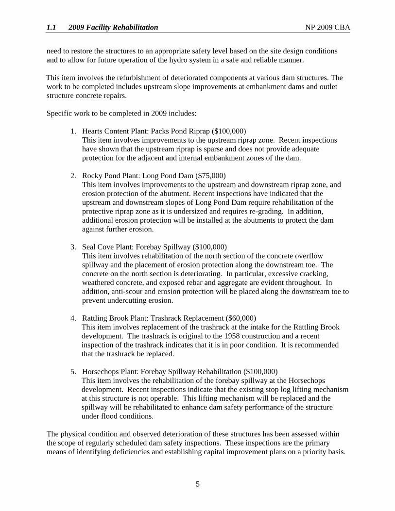
Figure 2 Figure 3 Figure 4 This item involves the replacement of the original potential and current transformers (Figure 2 and 3) with more reliable, accurate units. The control switches, meters and associated wiring will also be replaced with new equipment in the generating unit control panel. The power cables (Figure 4) leading from the generator to the switchgear and from the switchgear to the substation will be replaced with 1,000 MCM XLPE cables with slip on terminations. As a result of fault levels and clearing times at Horsechops there is a high arc flash hazard associated with this switchgear, requiring an arc flash boundary of 5.70 metres. To provide protection from this hazard walls will be constructed to separate the switchgear from the control room and the generator floor. 2.4 Plant Control System ($442,000) The Horsechops generator is controlled through various electromagnetic relays and switches from the original plant installation. This type of control does not allow for modernization of the plant, including the monitoring of automated water management5 routines remotely through the SCADA system. The water management system will optimize the efficiency of the plant by controlling unit loading based upon water level, inflow and wicket gate position. Monitoring of the system through SCADA will allow the operator to select water management mode for
5 Water management is an intelligent system of online monitoring of water levels and subsequent operation of the
plant in response to changing water levels.
1.1 2009 Facility Rehabilitation NP 2009 CBA
4
efficient operation and peak mode when requested to provide maximum generation by Newfoundland Hydro. The original Brown Boveri AB2/1 voltage regulator unit contains a mechanical operating mechanism that has been manufacturer discontinued. The voltage regulator has corrosion damage making its operation unreliable. This item involves the installation of a modern programmable logic controller (“PLC”) to provide full local and remote plant control. The PLC will interface with existing instrumentation and plant heating/cooling systems to provide an integrated control platform for the plant. As well, resulting control functionality will make possible the implementation of a variety of control modes, including water management and the capability to remotely black start the plant. A gateway data concentrator will provide communications to the SCADA system and access to data from the digital relays and PLC. 2.5 AC and DC Systems ($128,000) The existing 48-circuit AC distribution panel is 120/240 volt rated and is located in the switchgear. It does not have spare circuits available, and replacement breakers are not available due to the age of the equipment. It will be replaced with a standard 120/208V 60 circuit essential services panel and a 120/208V 60 circuit non-essential services panel located on the switchgear room wall. Both the normal and emergency services transformers will be replaced. Both transformers are original to the 1954 plant construction. The replacement units will provide a standard voltage rating AC service for the plant to provide improved reliability and ease of replacement in the future. The 20 circuit DC distribution panel was installed in 1985 and has 11 spare circuits available. The Varta 156 Amp-hour lead acid battery bank was installed in 1992 and the Staticon battery charger was installed in 1986. Typically battery chargers have a 15 year life expectancy while battery banks have a 20 year life expectancy. The DC panel will remain in service and the Staticon battery charger will be replaced. The battery bank will be replaced with gel cell technology to eliminate the requirement for a separate battery room to be constructed. 3.0 Hydro Dam Rehabilitation Cost: $435,000 Newfoundland Power has over 150 dam structures throughout its 23 hydroelectric facilities. Based on the average age of structures in the Newfoundland Power system, deterioration of embankment and concrete dams is to be expected. Refurbishment is required to ensure integrity of the structures is maintained to an appropriate level of dam safety as per the guidelines established by the Canadian Dam Association. The cost of the projects is justified based on the
1.1 2009 Facility Rehabilitation NP 2009 CBA
5
need to restore the structures to an appropriate safety level based on the site design conditions and to allow for future operation of the hydro system in a safe and reliable manner. This item involves the refurbishment of deteriorated components at various dam structures. The work to be completed includes upstream slope improvements at embankment dams and outlet structure concrete repairs.
Specific work to be completed in 2009 includes:
1. Hearts Content Plant: Packs Pond Riprap ($100,000)
This item involves improvements to the upstream riprap zone. Recent inspections have shown that the upstream riprap is sparse and does not provide adequate protection for the adjacent and internal embankment zones of the dam.
2. Rocky Pond Plant: Long Pond Dam ($75,000) This item involves improvements to the upstream and downstream riprap zone, and erosion protection of the abutment. Recent inspections have indicated that the upstream and downstream slopes of Long Pond Dam require rehabilitation of the protective riprap zone as it is undersized and requires re-grading. In addition, additional erosion protection will be installed at the abutments to protect the dam against further erosion.
3. Seal Cove Plant: Forebay Spillway ($100,000)
This item involves rehabilitation of the north section of the concrete overflow spillway and the placement of erosion protection along the downstream toe. The concrete on the north section is deteriorating. In particular, excessive cracking, weathered concrete, and exposed rebar and aggregate are evident throughout. In addition, anti-scour and erosion protection will be placed along the downstream toe to prevent undercutting erosion.
4. Rattling Brook Plant: Trashrack Replacement ($60,000)
This item involves replacement of the trashrack at the intake for the Rattling Brook development. The trashrack is original to the 1958 construction and a recent inspection of the trashrack indicates that it is in poor condition. It is recommended that the trashrack be replaced.
5. Horsechops Plant: Forebay Spillway Rehabilitation ($100,000)
This item involves the rehabilitation of the forebay spillway at the Horsechops development. Recent inspections indicate that the existing stop log lifting mechanism at this structure is not operable. This lifting mechanism will be replaced and the spillway will be rehabilitated to enhance dam safety performance of the structure under flood conditions.
The physical condition and observed deterioration of these structures has been assessed within the scope of regularly scheduled dam safety inspections. These inspections are the primary means of identifying deficiencies and establishing capital improvement plans on a priority basis.
1.1 2009 Facility Rehabilitation NP 2009 CBA
6
4.0 Generation Equipment Replacements Due to In-Service Failures Cost: $425,000 Equipment and infrastructure at generating facilities such as turbines and generators routinely requires upgrading or replacement to extend the life of the asset.
This item involves the refurbishment or replacement of structures and equipment due to damage, deterioration, corrosion, technical obsolescence and in-service failure. This equipment is critical to the safe and reliable operation of generating facilities and must be replaced in a timely manner. Equipment replaced under this item includes civil infrastructure, instrumentation, mechanical, electrical, and protection and controls equipment.
Replacements under this item are typically due to one of two reasons:
1. Emergency replacements – where components fail and require immediate
replacement to return a unit to service; or
2. Observed deficiencies – where components are identified for replacement due to imminent failure or for safety or environmental reasons.
Table 1 shows the expenditures for replacements due to in-service failures since 2004.
Table 1
Expenditures Due to In-Service Failures (000s)
Year 2004 2005 2006 2007 2008F Total $385 $5701 $5911 $409 $425
1 Excludes Rocky Pond rebuild.
Based upon this recent historical information and engineering judgement, $425,000 is estimated to be required in 2009 for replacement of equipment due to in-service failures or equipment at risk of imminent failure. Generation equipment, buildings, intakes, dams and control structures are critical components in the safe and reliable operation of generating facilities. This item is required to enable the timely refurbishment or replacement of equipment to facilitate the continued operation of generating facilities in a safe and reliable manner.
1.1 2009 Facility Rehabilitation NP 2009 CBA
7
5.0 Upgrade Plant Metering Cost: $100,000 Digital meters were initially installed in Newfoundland Power substations and hydroelectric plants to provide data for internal metering purposes including SCADA. With the introduction of the demand energy wholesale rate for electricity the digital meters in the power plants require monthly interrogation by Newfoundland and Labrador Hydro for revenue metering purposes. A number of problems have been experienced with the reliability and integrity of data obtained from the existing meters. The majority of the problems have resulted from errors in the meter’s time keeping-function. The meter’s internal clocks are inaccurate and drift several seconds per day, making it difficult to synchronize energy readings across all plants. The combination of data errors and poor time synchronization has caused delays for Newfoundland and Labrador Hydro in compiling the monthly energy bill. In addition, any time data has to be edited, the integrity of that data is questionable. Newfoundland Power plans to replace 25 of the existing digital meters in 2009 with revenue grade, SCADA capable meters that will provide reliable, accurate metering data to meet the requirements of Newfoundland and Labrador Hydro. 6.0 Engineering for Seal Cove Runner Replacement Cost: $10,000 Newfoundland Power’s Seal Cove hydroelectric generating plant is located approximately 20 kilometres from the City of St. John’s along the Conception Bay Highway. The plant was commissioned in 1924 and has a capacity of 3.5 MW. The normal annual production at Seal Cove is approximately 8.5 GWhr or 2.0% of the total hydroelectric production of Newfoundland Power. The plant has two turbine units: G1 of 1924 vintage with a nameplate capacity of 1.1 MW, and G2 of 1926 vintage with a nameplate capacity of 2.4 MW. Newfoundland Power has conducted various inspections of the major components of the G1 turbine. These inspections revealed severe deterioration of the turbine runner. The deterioration involves severe cavitation of the runner, as well as corrosion of the wicket gates such that the gates do not operate efficiently through their full range of motion. The extent of damage to the runner blades and wicket gates shown in Figures 5 and 6 is such that the runner is no longer able to operate efficiently and increases the risk of an in-service failure.

1.1 2009 Facility Rehabilitation NP 2009 CBA
8
Figure 5 Figure 6
Newfoundland Power currently plans to bring forward a capital budget project proposal for the replacement of G1 runner at Seal Cove plant in the 2010 Capital Budget Application. This capital project proposal will require detailed engineering design work to finalize the necessary budget estimates and schedules. Also the detailed design work will allow Newfoundland Power to prepare engineering specifications and tender documents in advance to ensure the project can be completed during the 2010 construction season. 7.0 Recommendations This project, for which there is no feasible alternative, is required in order to ensure the continued provision of safe, reliable plant operations. A 2009 budget of $1,917,000 for Facility Rehabilitation is recommended as follows:
• $947,000 for Horsechops Protection, Control and Governor Refurbishment; • $435,000 for Hydro Dam Rehabilitation; • $425,000 for Generation Equipment Replacements Due to In-Service Failures; • $100,000 for Upgrade Plant Metering; and • $10,000 for Engineering for Seal Cove Runner Replacement.
1.2 Rocky Pond Hydro Plant Refurbishment NP 2009 CBA
RaeJ.cy Bad Bydrs P la t Refmbbhment
June 2008
Prepared by:
Trina Connier, B.Eng.
Approved by:
Gary K. Humby, P.Eng.
1.2 Rocky Pond Hydro Plant Refurbishment NP 2009 CBA
i
Table of Contents
Page
1.0 Introduction.......................................................................................................................1 2.0 Background.......................................................................................................................1 3.0 Civil Works.......................................................................................................................3 3.1 Penstock ................................................................................................................3 3.2 Forebay Intake Structure.......................................................................................4 3.3 Civil Infrastructure................................................................................................5 4.0 Mechanical Works ............................................................................................................5 4.1 Main Inlet Valve ...................................................................................................5 4.2 Governor ...............................................................................................................6 5.0 Electrical Works................................................................................................................7 5.1 Generator Rewind .................................................................................................7 5. 2 Forebay Distribution Line.....................................................................................7 6.0 Project Execution ..............................................................................................................8 7.0 Project Cost.......................................................................................................................9 8.0 Feasibility Analysis.........................................................................................................10
Appendix A: Pictures of Rocky Pond Penstock Appendix B: Assessment of Rocky Pond Woodstave Penstock Appendix C: Project Schedule Appendix D: Feasibility Analysis
1.2 Rocky Pond Hydro Plant Refurbishment NP 2009 CBA
1
1.0 Introduction Newfoundland Power’s Rocky Pond/Tors Cove development is composed of two generating plants, Rocky Pond and Tors Cove, located on the southern shore of the Avalon Peninsula, approximately 40 km south of the City of St. John’s. Rocky Pond hydroelectric generating plant is located upstream of Tors Cove Pond. The plant was placed into service in 1942 and has a capacity of 3.25 MW under a net head of 32.6 m. The normal annual production at Rocky Pond is approximately 14.1 GWhr or 3.3 % of the total hydroelectric production of Newfoundland Power. The development has provided 66 years of reliable energy production to the Island Interconnected System. Newfoundland Power has determined that the woodstave penstock has reached the end of its useful life and requires replacement (See Appendix A for pictures of the penstock). In addition, the following work needs to be completed:
• Refurbish intake; • Replace main valve; • Rewind generator; • Implement governor upgrades; and • Rebuild forebay distribution and communication line.
This project is necessary at this time due to the age and physical condition of the plant assets. The woodstave penstock is 66 years old, is in poor condition and continues to deteriorate. It must be replaced in 2009. The intake gate and gate guides are original to the plant and require replacement. Replacement of the main valve; governor controls; rebuilding the forebay distribution line and communication cable will improve operation of the plant and provide low cost energy to the Island Interconnected System. Results of the feasibility analysis conclude that the continued operation of Rocky Pond plant, including the planned replacement and refurbishment project, is economically viable over the long term. This project will allow Newfoundland Power to continue to operate this facility into the future, maximizing the benefits of this renewable resource for its customers. 2.0 Background Newfoundland Power completed an assessment on the Rocky Pond Development to determine the project scope and verify the budget for the work to be completed. An engineering assessment was completed on the penstock by Hatch1 in November 2006. This assessment report is included in Appendix B. Appendix C includes the project schedule. Appendix D includes a feasibility analysis of the costs and benefits associated with the project.
1 Hatch, formerly SGE Acres, is a leading provider of process and business consulting, engineering project and
construction management to the energy, mining, metallurgical, manufacturing and infrastructure industries.
1.2 Rocky Pond Hydro Plant Refurbishment NP 2009 CBA
2
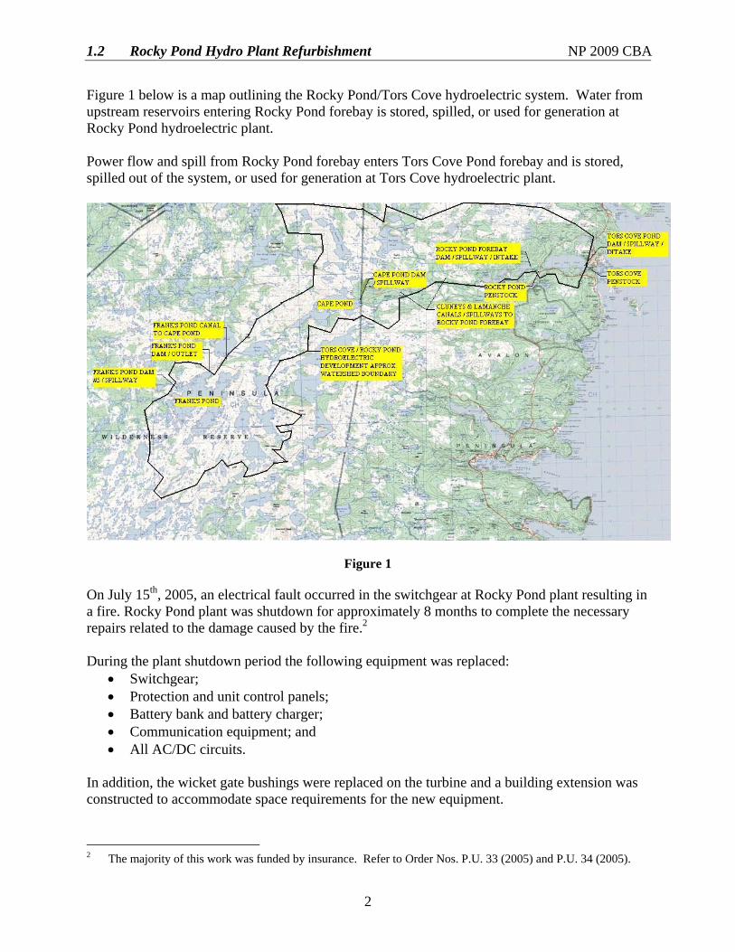
Figure 1 below is a map outlining the Rocky Pond/Tors Cove hydroelectric system. Water from upstream reservoirs entering Rocky Pond forebay is stored, spilled, or used for generation at Rocky Pond hydroelectric plant. Power flow and spill from Rocky Pond forebay enters Tors Cove Pond forebay and is stored, spilled out of the system, or used for generation at Tors Cove hydroelectric plant.
Figure 1
On July 15th, 2005, an electrical fault occurred in the switchgear at Rocky Pond plant resulting in a fire. Rocky Pond plant was shutdown for approximately 8 months to complete the necessary repairs related to the damage caused by the fire.2 During the plant shutdown period the following equipment was replaced:
• Switchgear; • Protection and unit control panels; • Battery bank and battery charger; • Communication equipment; and • All AC/DC circuits.
In addition, the wicket gate bushings were replaced on the turbine and a building extension was constructed to accommodate space requirements for the new equipment.
2 The majority of this work was funded by insurance. Refer to Order Nos. P.U. 33 (2005) and P.U. 34 (2005).

1.2 Rocky Pond Hydro Plant Refurbishment NP 2009 CBA
3
Other upgrades since the plant was commissioned in 1942 include: • New crane hoist installed - 1995; • Runner and wicket gates replaced - 1996; • New louver system installed - 2003; and • Plant roof and overhead door replaced - 2006.
No work is required on the above plant equipment at this time as a result of these past upgrades. An engineering assessment was completed on the penstock in November 2006. Engineering assessments were completed for the remaining systems in 2007 and early 2008. All major components of the Rocky Pond system have been reviewed. Based on the engineering assessment, the project scope and budget have been finalized and presented in this report. 3.0 Civil Works Engineering assessments have identified the following civil work to be completed:
• Replace the woodstave penstock; and • Replace the intake gate and gate guides.
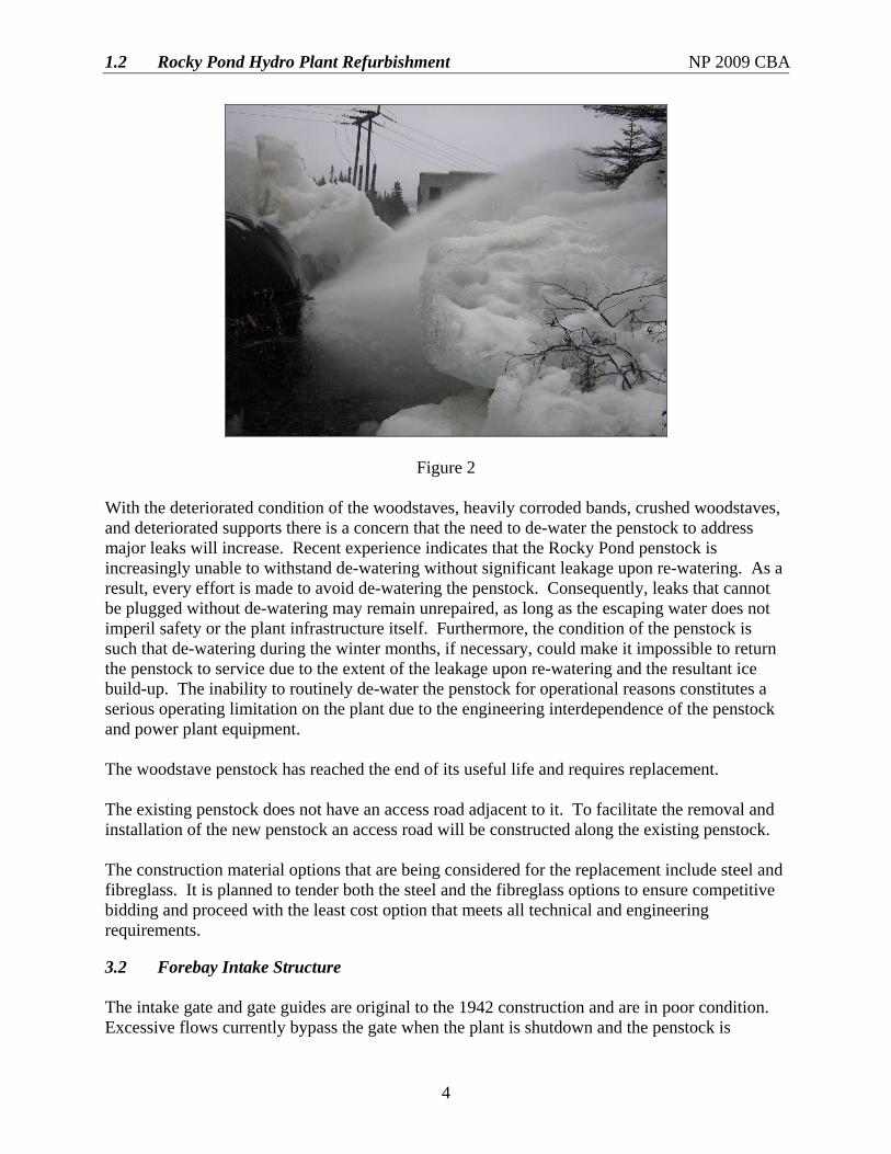
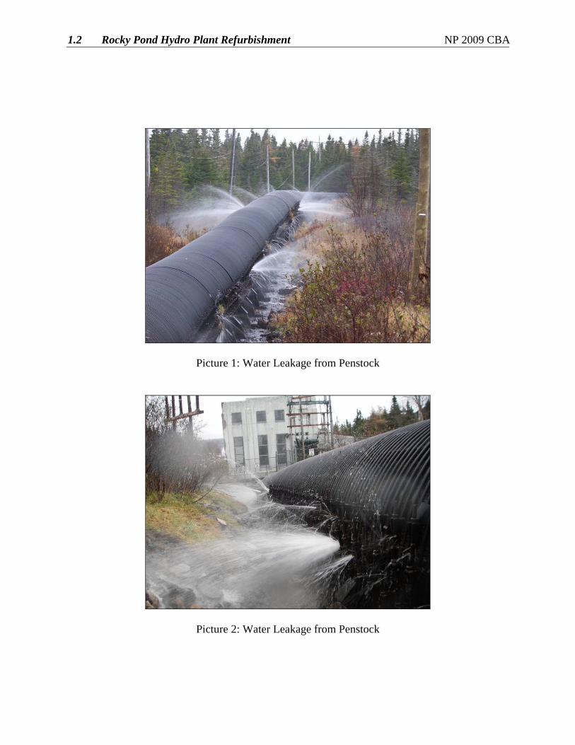
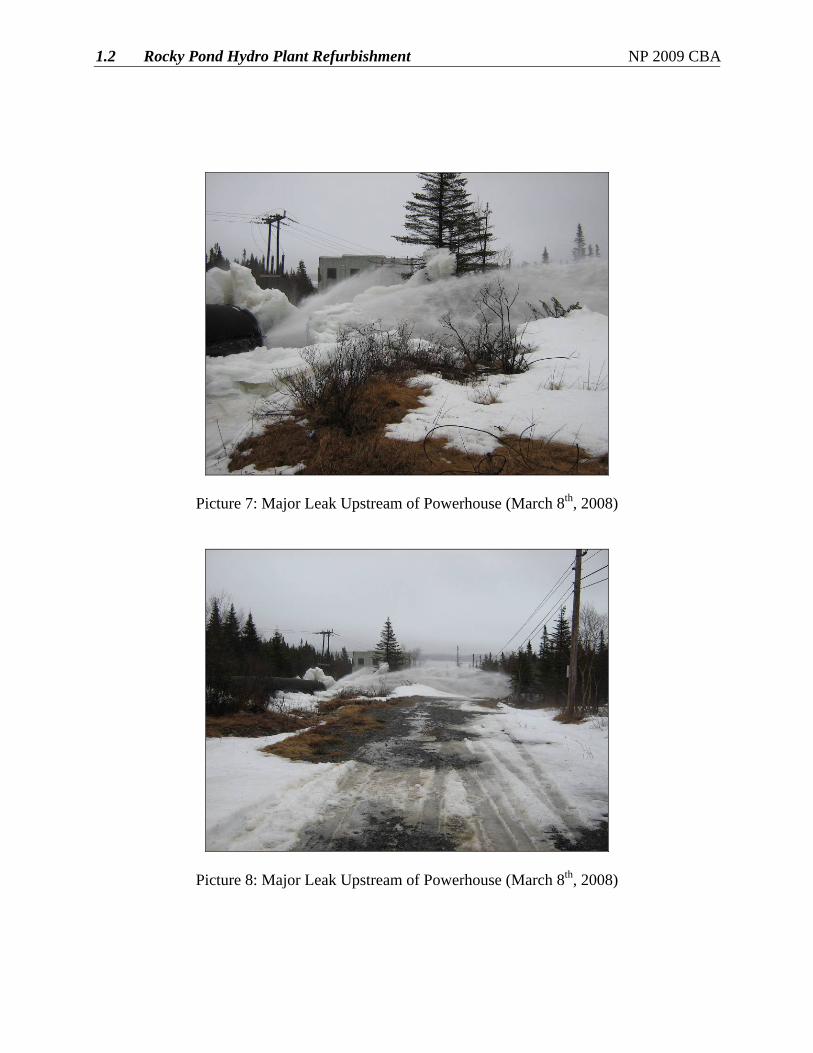
The penstock, intake gate and guides are original to plant construction in 1942. 3.1 Penstock The woodstave penstock is 66 years old and is in poor condition with deterioration along its entire length. The penstock bedding is saturated due to significant leakage from the penstock. There is also a bog located along the upper half of the penstock that appears to be contributing to the saturation of the bedding. Saturation of the penstock bedding has resulted in settlement of the support cradles into the soil bed. In addition several of the support cradles have been undermined by the heavy water flows along the length of the penstock. The steel bands are heavily corroded in areas of extensive leakage. The woodstaves are also rotting in several areas. This is largely attributable to the settlement of support cradles in the penstock bedding, poor drainage, and lack of ventilation in these areas. In recent years attempts have been made to divert the water flow to improve drainage and ventilation along the penstock. However, the water flow remains excessive and continues to be a contributing factor to the ongoing deterioration of the penstock. On March 8, 2008, a substantial leak developed in the penstock upstream of the power plant. Water flow from the leak prohibited the repair of the damage with the plant in operation. Therefore, the plant was taken out of service, the penstock dewatered and the leak repaired. A picture of this leak is included as Figure 2, while other pictures of the leak are included in Appendix A.
1.2 Rocky Pond Hydro Plant Refurbishment NP 2009 CBA
4
Figure 2 With the deteriorated condition of the woodstaves, heavily corroded bands, crushed woodstaves, and deteriorated supports there is a concern that the need to de-water the penstock to address major leaks will increase. Recent experience indicates that the Rocky Pond penstock is increasingly unable to withstand de-watering without significant leakage upon re-watering. As a result, every effort is made to avoid de-watering the penstock. Consequently, leaks that cannot be plugged without de-watering may remain unrepaired, as long as the escaping water does not imperil safety or the plant infrastructure itself. Furthermore, the condition of the penstock is such that de-watering during the winter months, if necessary, could make it impossible to return the penstock to service due to the extent of the leakage upon re-watering and the resultant ice build-up. The inability to routinely de-water the penstock for operational reasons constitutes a serious operating limitation on the plant due to the engineering interdependence of the penstock and power plant equipment. The woodstave penstock has reached the end of its useful life and requires replacement. The existing penstock does not have an access road adjacent to it. To facilitate the removal and installation of the new penstock an access road will be constructed along the existing penstock. The construction material options that are being considered for the replacement include steel and fibreglass. It is planned to tender both the steel and the fibreglass options to ensure competitive bidding and proceed with the least cost option that meets all technical and engineering requirements. 3.2 Forebay Intake Structure The intake gate and gate guides are original to the 1942 construction and are in poor condition. Excessive flows currently bypass the gate when the plant is shutdown and the penstock is
1.2 Rocky Pond Hydro Plant Refurbishment NP 2009 CBA
5
dewatered. This prohibits safe access to the intake when the penstock is dewatered to perform regular inspection and maintenance on the intake. It is recommended that the intake gate and gate guides be replaced. 3.3 Civil Infrastructure Assessments were completed of the civil infrastructure at Rocky Pond/Tors Cove in 2007 as part of Newfoundland Power’s Dam Safety program. The assessment included an inspection of all the dams, dykes, spillways and other outlet structures for both developments. Overall the civil infrastructure for the Rocky Pond development is in good condition. However, riprap improvements are required for Rocky Pond Long Pond dam. Refer to the “Facilities Rehabilitation” report of Newfoundland Power’s 2009 Capital Budget Application for a description of this project. 4.0 Mechanical Works The majority of the mechanical equipment has been upgraded and/or replaced in recent years with the exception of the main inlet valve and the governor. 4.1 Main Inlet Valve The main inlet valve at Rocky Pond is a 2,134 mm (84 in) butterfly valve manufactured by Dominion Engineering Works Ltd. (Montreal, Canada) in 1942. The valve is electrically actuated. An internal inspection of the valve performed during a recent plant shutdown revealed that the valve was not sealing properly in the closed position creating a constant flow of high pressure water into the turbine. This leakage prevents safe access to the scroll case without having to dewater the penstock each time work is required on the turbine. The current limitations imposed on the operation of the plant as a result of the need to avoid de-watering the penstock, together with the leaking of the main valves, limit the Company’s ability to maintain and service other equipment in the plant. Typically, the main valve is accompanied by a bypass valve and drain valve. However, the main valve arrangement at Rocky Pond is accompanied by a drain valve only. The drain valve is a manual valve that is used to drain the penstock for maintenance. The function of a bypass valve is to direct water past the main valve prior to opening thereby equalizing pressure on both sides of the main valve to reduce the strain associated with opening such a large valve. The lack of a bypass valve puts additional strain on the current main valve arrangement during opening and appears to be a contributing factor to the excessive leakage around the valve seal. The control panel for the main valve has been modified since its initial installation; however, the controls for the unit are obsolete. This control panel will be replaced. Based on the age and condition, the main valve, drain valve and associated equipment will be replaced. In addition, a bypass valve will be incorporated into the redesign of the main valve arrangement.
1.2 Rocky Pond Hydro Plant Refurbishment NP 2009 CBA
6
4.2 Governor
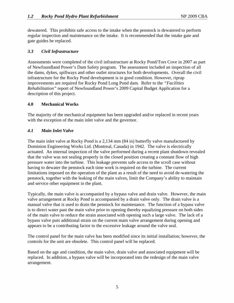
The governor is a Woodward Model HR and is original to the plant construction in 1942 (See Figure 3). An assessment of the governor was completed in 2007. Overall the hydraulic power portion of the governor is in good condition but does require a minor mechanical overhaul. The original equipment manufacturer has declared this model of governor to be obsolete and no longer manufactures replacement parts. A number of third party companies provide maintenance support, including parts, but these companies and the utility industry is moving towards replacing the hydraulic control portion of these governors with digital systems that provide enhanced control and feedback capabilities. Figure 3
An assessment of the governor was completed in 2007. Overall the hydraulic power portion of the governor is in good condition but does require a minor mechanical overhaul. The original equipment manufacturer has declared this governor to be obsolete and no longer manufactures replacement parts. A number of third party companies provide maintenance support, including parts, but these companies and the utility industry is moving towards replacing the hydraulic control portion of these governors with digital systems that provide enhanced control and feedback capabilities. In 2006 a water management system was implemented into the PLC to optimize loading of the unit. In order to avail of better unit control and operation with the PLC based control system, the governors will be upgraded with a new electronic head similar to the installation at Rattling Brook in 2007. The hydraulic power portion of the governor is in good condition and will be retained. The hydraulic control portion of the governor, above the relay valve, will be removed and a PLC based digital control system installed. The Woodward Combination Speed Switch will no longer be required to supply speed feedback to the governor so it will be removed, except for the tooth gear, on which new speed sensors will be installed. The new governor control will provide more precise speed control.
1.2 Rocky Pond Hydro Plant Refurbishment NP 2009 CBA
7
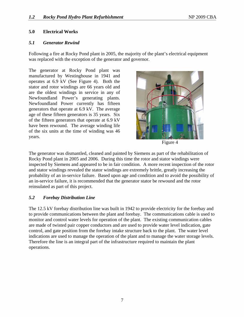
5.0 Electrical Works 5.1 Generator Rewind Following a fire at Rocky Pond plant in 2005, the majority of the plant’s electrical equipment was replaced with the exception of the generator and governor.
The generator at Rocky Pond plant was manufactured by Westinghouse in 1941 and operates at 6.9 kV (See Figure 4). Both the stator and rotor windings are 66 years old and are the oldest windings in service in any of Newfoundland Power’s generating plants. Newfoundland Power currently has fifteen generators that operate at 6.9 kV. The average age of these fifteen generators is 35 years. Six of the fifteen generators that operate at 6.9 kV have been rewound. The average winding life of the six units at the time of winding was 46 years.
Figure 4 The generator was dismantled, cleaned and painted by Siemens as part of the rehabilitation of Rocky Pond plant in 2005 and 2006. During this time the rotor and stator windings were inspected by Siemens and appeared to be in fair condition. A more recent inspection of the rotor and stator windings revealed the stator windings are extremely brittle, greatly increasing the probability of an in-service failure. Based upon age and condition and to avoid the possibility of an in-service failure, it is recommended that the generator stator be rewound and the rotor reinsulated as part of this project. 5.2 Forebay Distribution Line The 12.5 kV forebay distribution line was built in 1942 to provide electricity for the forebay and to provide communications between the plant and forebay. The communications cable is used to monitor and control water levels for operation of the plant. The existing communication cables are made of twisted pair copper conductors and are used to provide water level indication, gate control, and gate position from the forebay intake structure back to the plant. The water level indications are used to manage the operation of the plant and to manage the water storage levels. Therefore the line is an integral part of the infrastructure required to maintain the plant operations.
1.2 Rocky Pond Hydro Plant Refurbishment NP 2009 CBA
8
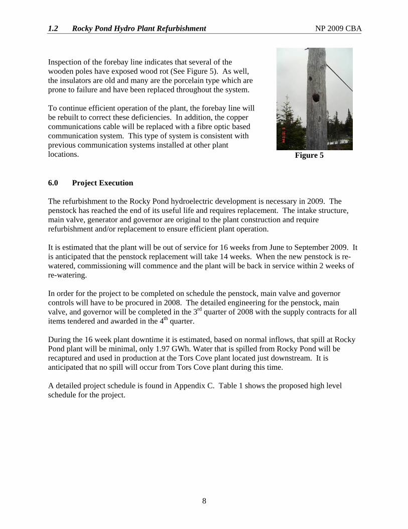
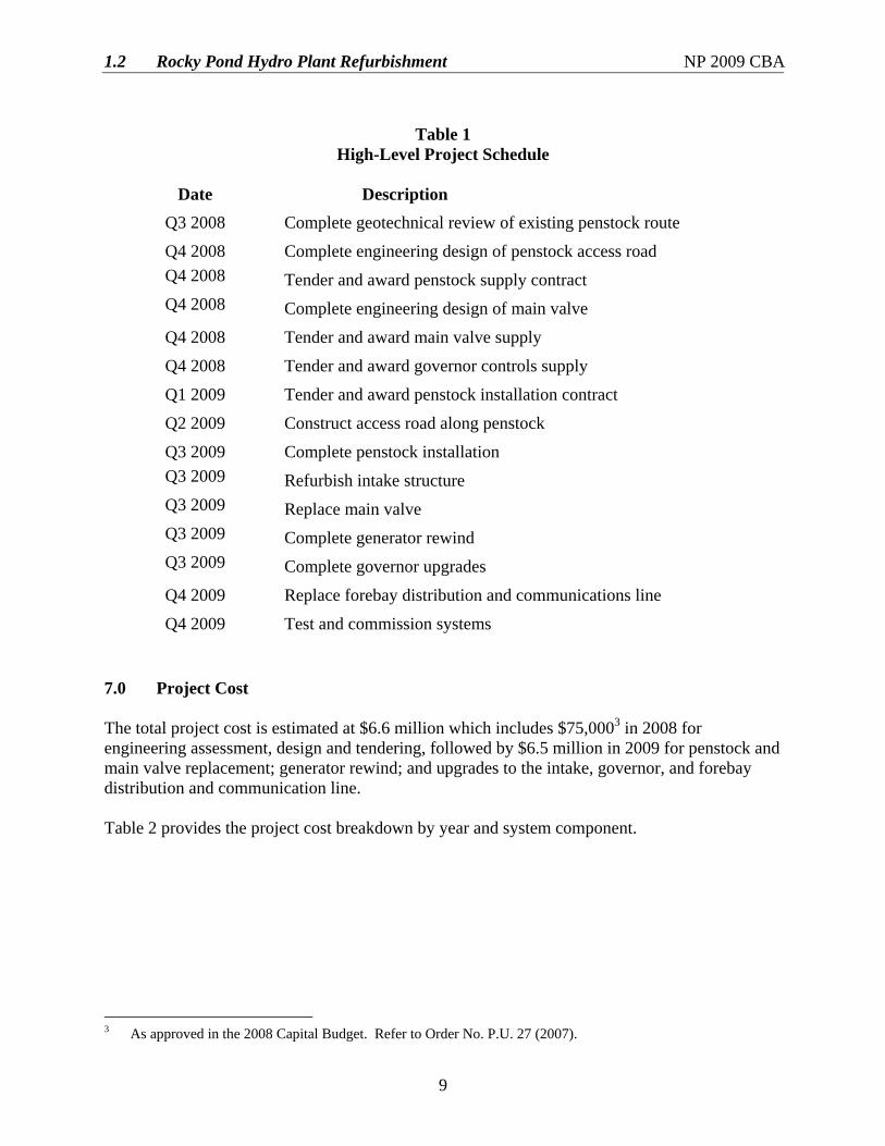
Inspection of the forebay line indicates that several of the wooden poles have exposed wood rot (See Figure 5). As well, the insulators are old and many are the porcelain type which are prone to failure and have been replaced throughout the system. To continue efficient operation of the plant, the forebay line will be rebuilt to correct these deficiencies. In addition, the copper communications cable will be replaced with a fibre optic based communication system. This type of system is consistent with previous communication systems installed at other plant locations. Figure 5 6.0 Project Execution The refurbishment to the Rocky Pond hydroelectric development is necessary in 2009. The penstock has reached the end of its useful life and requires replacement. The intake structure, main valve, generator and governor are original to the plant construction and require refurbishment and/or replacement to ensure efficient plant operation. It is estimated that the plant will be out of service for 16 weeks from June to September 2009. It is anticipated that the penstock replacement will take 14 weeks. When the new penstock is re-watered, commissioning will commence and the plant will be back in service within 2 weeks of re-watering. In order for the project to be completed on schedule the penstock, main valve and governor controls will have to be procured in 2008. The detailed engineering for the penstock, main valve, and governor will be completed in the 3rd quarter of 2008 with the supply contracts for all items tendered and awarded in the 4th quarter. During the 16 week plant downtime it is estimated, based on normal inflows, that spill at Rocky Pond plant will be minimal, only 1.97 GWh. Water that is spilled from Rocky Pond will be recaptured and used in production at the Tors Cove plant located just downstream. It is anticipated that no spill will occur from Tors Cove plant during this time. A detailed project schedule is found in Appendix C. Table 1 shows the proposed high level schedule for the project.
1.2 Rocky Pond Hydro Plant Refurbishment NP 2009 CBA
9
Table 1
High-Level Project Schedule
Date Description Q3 2008 Complete geotechnical review of existing penstock route
Q4 2008 Complete engineering design of penstock access road Q4 2008 Tender and award penstock supply contract Q4 2008 Complete engineering design of main valve
Q4 2008 Tender and award main valve supply
Q4 2008 Tender and award governor controls supply
Q1 2009 Tender and award penstock installation contract
Q2 2009 Construct access road along penstock
Q3 2009 Complete penstock installation Q3 2009 Refurbish intake structure Q3 2009 Replace main valve Q3 2009 Complete generator rewind Q3 2009 Complete governor upgrades
Q4 2009 Replace forebay distribution and communications line
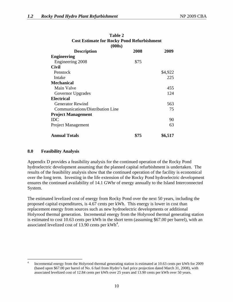
Q4 2009 Test and commission systems 7.0 Project Cost The total project cost is estimated at $6.6 million which includes $75,0003 in 2008 for engineering assessment, design and tendering, followed by $6.5 million in 2009 for penstock and main valve replacement; generator rewind; and upgrades to the intake, governor, and forebay distribution and communication line. Table 2 provides the project cost breakdown by year and system component.
3 As approved in the 2008 Capital Budget. Refer to Order No. P.U. 27 (2007).
1.2 Rocky Pond Hydro Plant Refurbishment NP 2009 CBA
10
Table 2
Cost Estimate for Rocky Pond Refurbishment (000s)
Description 2008 2009 Engineering
Engineering 2008 $75 Civil
Penstock $4,922 Intake 225
Mechanical Main Valve 455 Governor Upgrades 124
Electrical Generator Rewind 563 Communications/Distribution Line 75
Project Management IDC 90 Project Management 63 Annual Totals $75 $6,517
8.0 Feasibility Analysis Appendix D provides a feasibility analysis for the continued operation of the Rocky Pond hydroelectric development assuming that the planned capital refurbishment is undertaken. The results of the feasibility analysis show that the continued operation of the facility is economical over the long term. Investing in the life extension of the Rocky Pond hydroelectric development ensures the continued availability of 14.1 GWhr of energy annually to the Island Interconnected System. The estimated levelized cost of energy from Rocky Pond over the next 50 years, including the proposed capital expenditures, is 4.67 cents per kWh. This energy is lower in cost than replacement energy from sources such as new hydroelectric developments or additional Holyrood thermal generation. Incremental energy from the Holyrood thermal generating station is estimated to cost 10.63 cents per kWh in the short term (assuming $67.00 per barrel), with an associated levelized cost of 13.90 cents per kWh4.
4 Incremental energy from the Holyrood thermal generating station is estimated at 10.63 cents per kWh for 2009
(based upon $67.00 per barrel of No. 6 fuel from Hydro’s fuel price projection dated March 31, 2008), with associated levelized cost of 12.84 cents per kWh over 25 years and 13.90 cents per kWh over 50 years.

1.2 Rocky Pond Hydro Plant Refurbishment NP 2009 CBA
Appendix A
Pictures of Rocky Pond Penstock
1.2 Rocky Pond Hydro Plant Refurbishment NP 2009 CBA
Picture 1: Water Leakage from Penstock
Picture 2: Water Leakage from Penstock
1.2 Rocky Pond Hydro Plant Refurbishment NP 2009 CBA
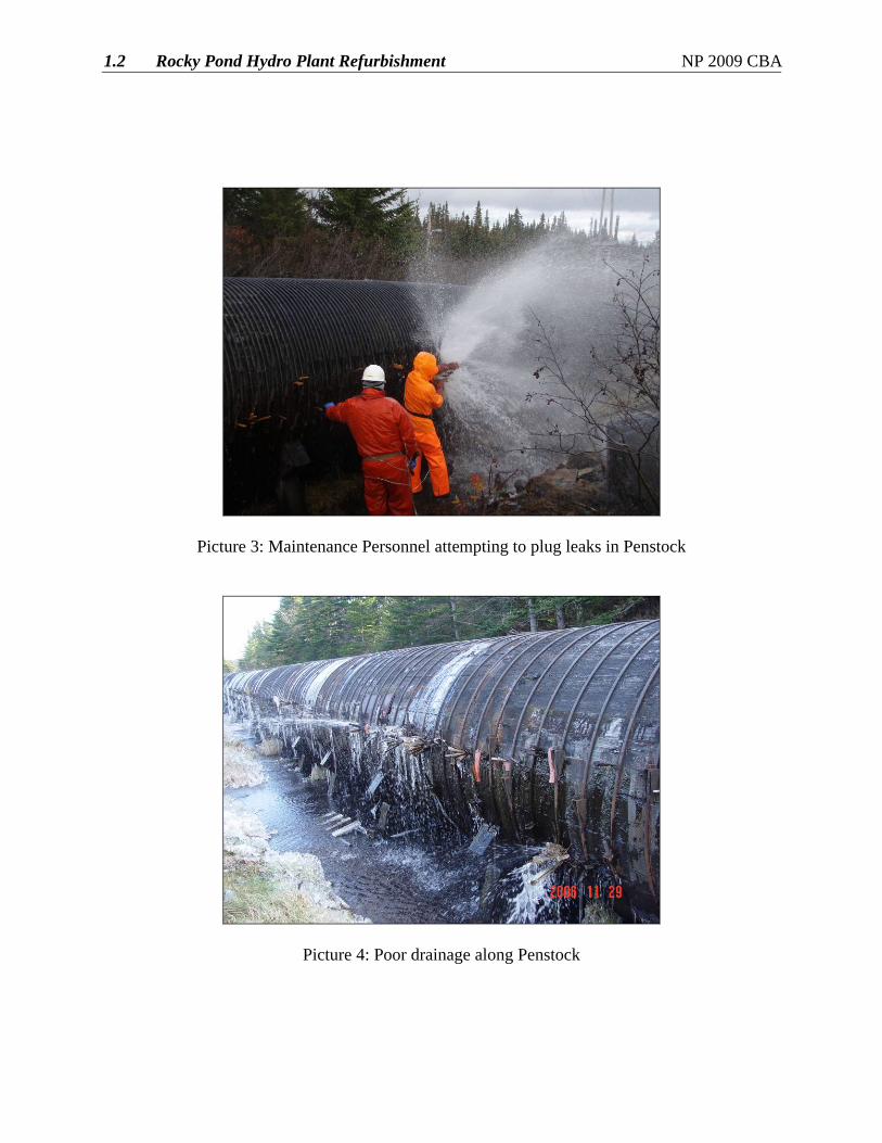
Picture 3: Maintenance Personnel attempting to plug leaks in Penstock
Picture 4: Poor drainage along Penstock
1.2 Rocky Pond Hydro Plant Refurbishment NP 2009 CBA
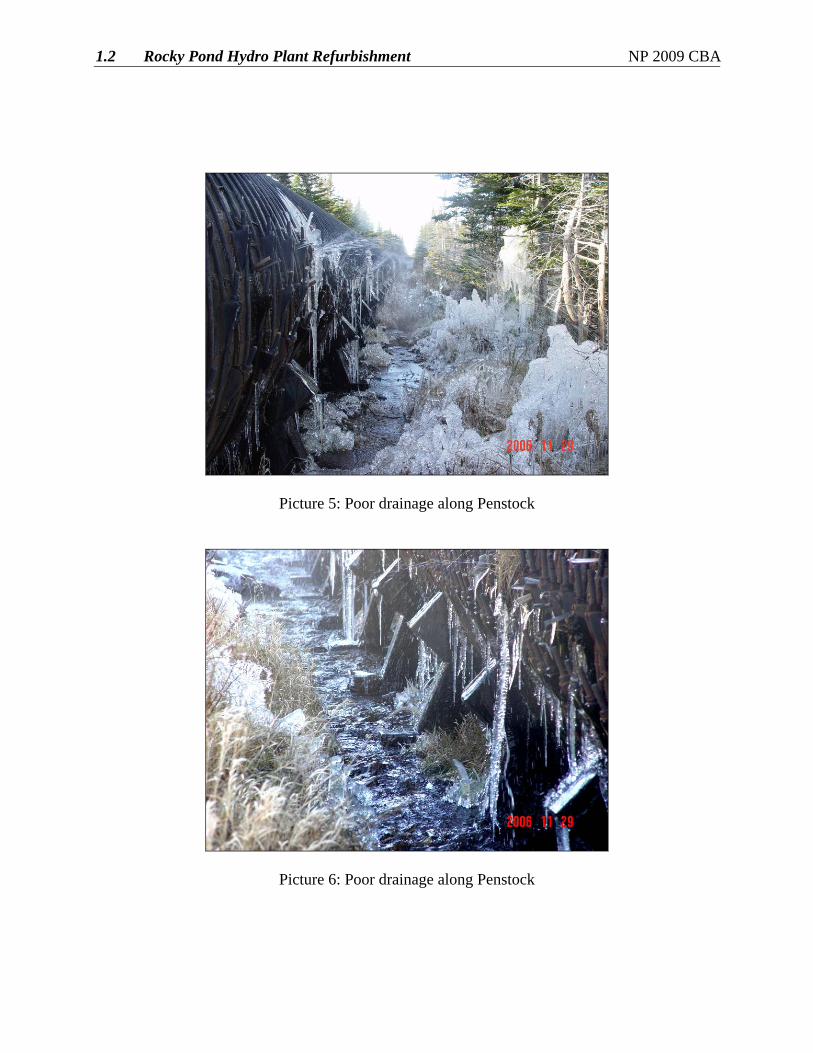
Picture 5: Poor drainage along Penstock
Picture 6: Poor drainage along Penstock
1.2 Rocky Pond Hydro Plant Refurbishment NP 2009 CBA
Picture 7: Major Leak Upstream of Powerhouse (March 8th, 2008)
Picture 8: Major Leak Upstream of Powerhouse (March 8th, 2008)
1.2 Rocky Pond Hydro Plant Refurbishment NP 2009 CBA
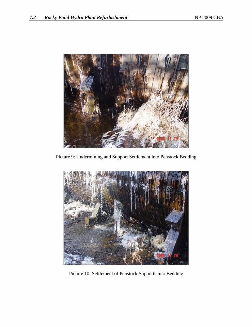
Picture 9: Undermining and Support Settlement into Penstock Bedding
Picture 10: Settlement of Penstock Supports into Bedding
1.2 Rocky Pond Hydro Plant Refurbishment NP 2009 CBA
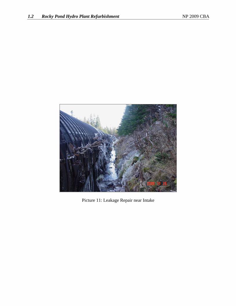
Picture 11: Leakage Repair near Intake

1.2 Rocky Pond Hydro Plant Refurbishment NP 2009 CBA
Appendix B
Hatch: Assessment of Rocky Pond Woodstave Penstock
Newfoundland Power - Assessment of Rocky Pond Woodstave Penstock
Final Report - December 2006
ISO 9001 PRH-324668. Rev. 0, Page 1-1
H-324668 - Formatted Final Report © Hatch 2006/03
1. Introduction
1.1 Authorization On November 16, 2006, Newfoundland Power engaged Hatch to carry out a visual inspection and prepare a summary report on the condition of woodstave penstock of the company’s Rocky Pond Hydroelectric Development. The work was undertaken based on a proposal submitted by Hatch on November 6, 2006.
1.2 Scope of Inspection and Report The scope of the inspection included a visual inspection to ascertain the general state and condition of the penstock, a summary report describing the condition and findings and inclusion of a subjective opinion of the useful life of the penstock. The penstock is nearing the end of its useful life and non-destructive testing such as wood cores sample testing was deemed unnecessary.
1.3 Background Available information included four drawings, as follows:
• Intake and Conduit under dam dated April 7, 1942
• Revised W.S. Pipeline Location No. R-4, dated February 17, 1942
• Preliminary profile No. NF-1852, dated January 5, 1942
• Profile- Pipeline Sub-Grade, No. R-8, dated August 5, 1942
The Rocky Pond/Tors Cove Hydroelectric System is located on the southern shore of the Avalon Peninsula and has two generating stations, Rocky Pond and Tors Cove. The facility was commissioned in 1943. The Rocky Pond Generating Station has one unit with an installed capacity of 3.25 MW with a rated head of 32.6 m (107 feet). The local datum centerline elevation of the turbine distributor is 88 m (289 feet). The penstock has an approximate 10 degree curve to the south just downstream of the intake and a 29 degree curve to the north at about 304.8 m (1000 feet) downstream of the intake. The soil bed has 7 slope changes along its length with slopes ranging from 1 degree up to 15 degrees near the powerhouse. The penstock does not contain any anchor blocks or movement joints. The penstock is crossed by a road bridge upstream of the powerhouse.
The 2.29 m (7.5 foot) nominal diameter by 756 m (2480 feet long) woodstave penstock is configured as follows: 716 m (2349 linear feet) of 2.273 m (89½ inch) inside diameter pipe with 66.7 mm (2 5/8 inch) thick staves and 39.9 m (131 linear feet), near the powerhouse, with 2.261 m (89 inch) inside diameter pipe with 79.4 mm (3 1/8 inch) thick staves.
The pipe is banded with approximately 19 mm (¾ inch) diameter steel bands which vary in spacing from approximately 75 mm (3 inches) at the powerhouse to approximately 200 mm (8 inches) at the intake conduit end.
The pipe is supported on timber cradles which contain about 120 degree portion of the pipe. The cradles are constructed out of 150 mm (6 inch) by 200 mm (8 inch) timber.

Newfoundland Power - Assessment of Rocky Pond Woodstave Penstock
Final Report - December 2006
ISO 9001 PRH-324668. Rev. 0, Page 1-2
H-324668 - Formatted Final Report © Hatch 2006/03
The timber staves and the cradles are pressure treated with creosote.
The penstock is the original pipeline installed in 1942.
The normal static head at the powerhouse is 290 kPa (42 psi). The highest penstock pressure upon 100% load rejection, measured in 2006, was 586 kPa (85 psi).

Newfoundland Power - Assessment of Rocky Pond Woodstave Penstock
Final Report - December 2006
ISO 9001 PRH-324668. Rev. 0, Page 2-1
H-324668 - Formatted Final Report © Hatch 2006/03
2. Inspection Mr. Walter Smith, P.Eng., of Hatch Energy carried out the visual inspection on November 29, 2006. Mr. Gary Murray, P.Eng., and Ms. Trina Cormier, B. Eng., of Newfoundland Power accompanied Mr. Smith during the inspection. The weather was clear with the temperature at minus 4 Celsius. A series of photographs were taken to record the pipeline condition as it was walked upstream on the south side and downstream on the north.
Newfoundland Power - Assessment of Rocky Pond Woodstave Penstock
Final Report - December 2006
ISO 9001 PRH-324668. Rev. 0, Page 3-1
H-324668 - Formatted Final Report © Hatch 2006/03
3. Penstock Condition
3.1 Pipe Condition The pipeline is leaking significantly along its entire length. This is highlighted by the extensive icing on the trees, bushes shrubs and grass along the entire length.
The soil bed is firm but wet over its entire length. The soil bed drains freely but the drainage water surface is much higher on the pipeline than is normally desirable. The source of the water is believed to be primarily from within the pipeline; however, there is bog along the flat area, on the upper half, which is contributing.
Near the powerhouse, Newfoundland Power has in recent years cut off and diverted approximately 50% of the water flowing from the leakage from the penstock and bog, to the back of the powerhouse. It is now diverted to the south bank of the tailrace. However, there is still too much water to be handled at the pipeline under the repair bay slab to the north side of the tailrace.
The penstock is sagging moderately in some areas due to settlement and/or sinking of the support cradles into the soil bed.
The cradle assemblies exhibit some cracks in the retaining segments. These cracks have been reinforced with steel plates and bolts. A few of the cradle sills or sleepers have been undercut by the heavy flows along either side particularly near the powerhouse end.
The steel bands are heavily corroded especially in the upstream half where there is extensive leakage and little ventilation. In one location there were three bands missing, one which had completely failed due to corrosion.
The staves are significantly deteriorated in several areas and suffer badly from the lack of ventilation due to the cradles sinking into the soil, bush and shrub growth and location of the pipeline bed through an excavated trench, particularly in the upstream half of the pipeline.
The pipeline was constructed without the use of metal end butts resulting in quite a number of split-outs at the end joints of the staves. These are retained by various repair types using steel plates with rubber gaskets or wood slats placed and held by the bands. In some locations the bands have completely failed. This is mainly caused by the lack of keepers (a ridge forming part of the shoe) which are found in the more modern band shoe designs and retain the washer and nut from slipping off. The timber staves also exhibit brooming, flaking, feathering and crushing between the steel bands.
The leaks have been repaired by various methods over the years. Large leaks and end split-outs are contained by placing large plates and rubber gaskets under the bands. At the spring line tapered wedges are driven in. In other areas sod is placed and retained to reduce the leakage.
Creosote has leached out of the wood especially in the flatter areas of the pipeline near the intake dam. The embedded steel thimble is corroded at the intake.
3.2 Photographs A series of photographs are included in Appendix A.
Newfoundland Power - Assessment of Rocky Pond Woodstave Penstock
Final Report - December 2006
ISO 9001 PRH-324668. Rev. 0, Page 4-1
H-324668 - Formatted Final Report © Hatch 2006/03
4. Conclusions and Recommendations
4.1 Conclusions The Rocky Pond Penstock is approximately 64 years old , is in very poor condition, leaks significantly and is nearing the end of its useful life. The life span for a woodstave penstock can vary and can be up to 60 years in many cases and is dependent on a number of factors: including the design thickness and design hardware, steel quality, timber species and quality, wood treatment quality, the saddle or cradle design, the extent of annual maintenance, and so on. The generating facilities day to day operation, including starts and stops, load changes and the number of times the pipeline is drained and refilled also impact its useful life.
In the case of the Rocky Pond Penstock, it has been favoured by having a moderately low hydraulic head but has been plagued by the poor drainage and ventilation conditions. The cradles support the pipeline over about a 120 degree arc. Modern woodstave pipeline designs have support up to 160 degrees. The higher support level confines the pipe better and results in fewer cycles from round to oval, during day to day operation and during periodic emptying and refilling.
The pipeline poses no obvious threat of sudden collapse or failure. Water loss has not been measured but it could easily be leaking as much as 10% of its carrying capacity or more.
The pipeline bed and its location, largely in an excavation, are preventing proper drainage and ventilation. The result is continued rotting of the timber staves and supports and continued corrosion of the bands and accompanying hardware.
4.2 Recommendations Based on the condition, extent of deterioration and potential for failure, it is recommended that the penstock be replaced.
Considerations for the replacement should include:
• Improvement in bed support and drainage along its route to ensure adequate ventilation for the new pipeline. This could be accomplished by raising the bed level and/or extensive local drainage ditches and diversions to carry water away from the pipeline and soil bed.
• An access road along its length will be required to re-construct the new pipeline.
• The most cost effective replacement materials.
Interim repair and upkeep recommendations include the following:
• Improve drainage where practical along the soil bed.
• Improve the ventilation near the bottom of the penstock by removal of shrubs and grass. Excavate soil where practical to effect this.
• Drain the submerged area at the intake and at the powerhouse to the extent it is practical to do so.
• Carryout routine leak repair and band tightening.

Newfoundland Power - Assessment of Rocky Pond Woodstave Penstock
Final Report - December 2006
ISO 9001 PRH-324668. Rev. 0, Page 4-2
H-324668 - Formatted Final Report © Hatch 2006/03
• Repair undercut cradle components.
• Repair strut and segment split-outs in the cradles.
• Replace missing steel bands.
• Make sure areas of ice build-up do not extend to the point where the pipeline can be jacked up by ice. This can be monitored by occasional inspections by operating staff.
• Treat the timber and woodstaves with wood preservative where deemed necessary.
• Remove debris from the penstock at the road crossing.
• Clean and paint the exposed thimble at the intake.

Newfoundland Power - Assessment of Rocky Pond Woodstave Penstock
Final Report - December 2006
ISO 9001 PRH-324668. Rev. 0
H-324668 - Formatted Final Report © Hatch 2006/03
Appendix A Photographs
Newfoundland Power - Assessment of Rocky Pond Woodstave Penstock
Final Report - December 2006
ISO 9001 PRH-324668. Rev. 0, Page 1
H-324668 - Formatted Final Report © Hatch 2006/03
A.1 Photographs
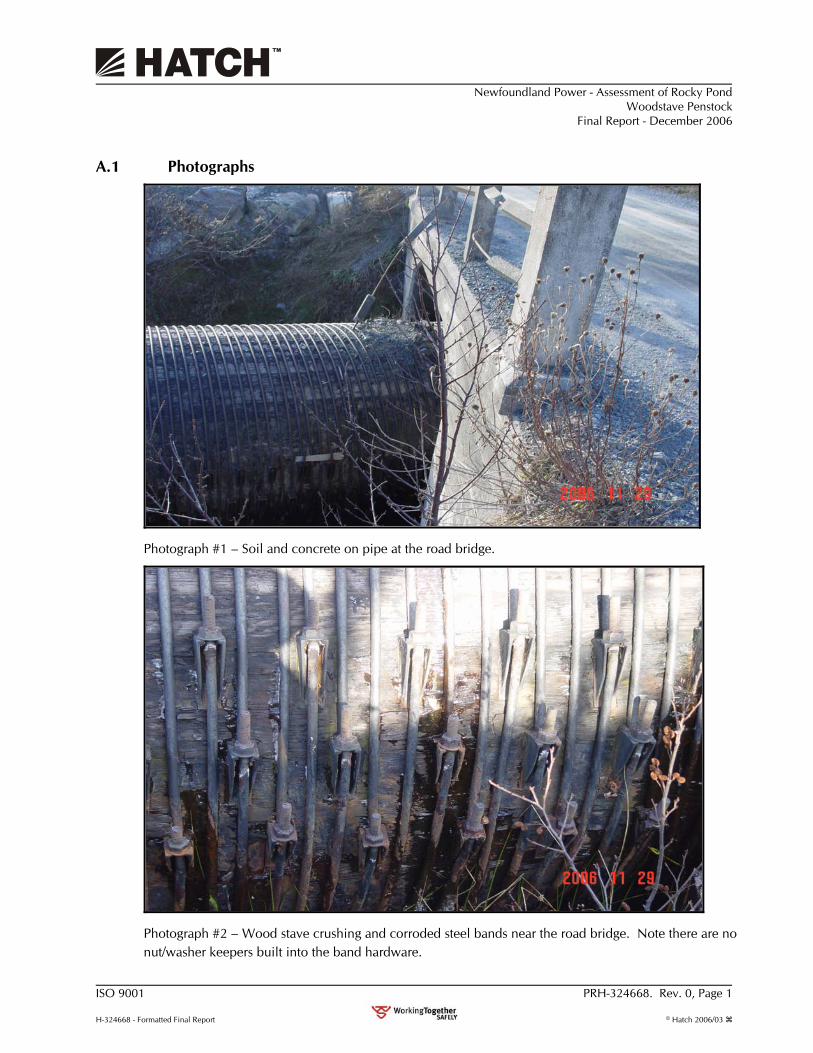
Photograph #1 – Soil and concrete on pipe at the road bridge.
Photograph #2 – Wood stave crushing and corroded steel bands near the road bridge. Note there are no nut/washer keepers built into the band hardware.
Newfoundland Power - Assessment of Rocky Pond Woodstave Penstock
Final Report - December 2006
ISO 9001 PRH-324668. Rev. 0, Page 2
H-324668 - Formatted Final Report © Hatch 2006/03
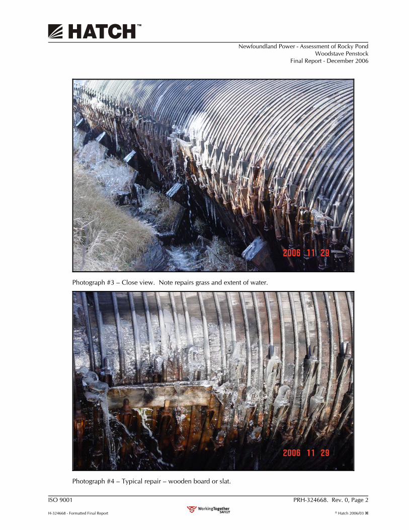
Photograph #3 – Close view. Note repairs grass and extent of water.
Photograph #4 – Typical repair – wooden board or slat.
Newfoundland Power - Assessment of Rocky Pond Woodstave Penstock
Final Report - December 2006
ISO 9001 PRH-324668. Rev. 0, Page 3
H-324668 - Formatted Final Report © Hatch 2006/03
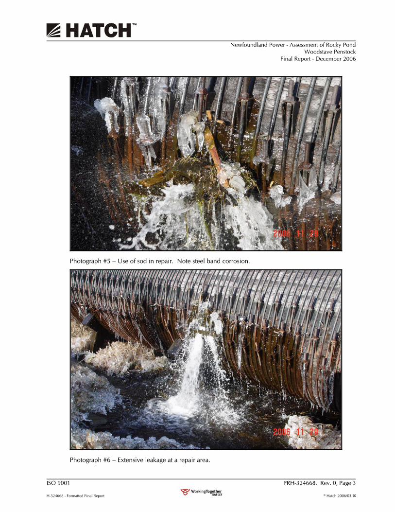
Photograph #5 – Use of sod in repair. Note steel band corrosion.
Photograph #6 – Extensive leakage at a repair area.
Newfoundland Power - Assessment of Rocky Pond Woodstave Penstock
Final Report - December 2006
ISO 9001 PRH-324668. Rev. 0, Page 4
H-324668 - Formatted Final Report © Hatch 2006/03
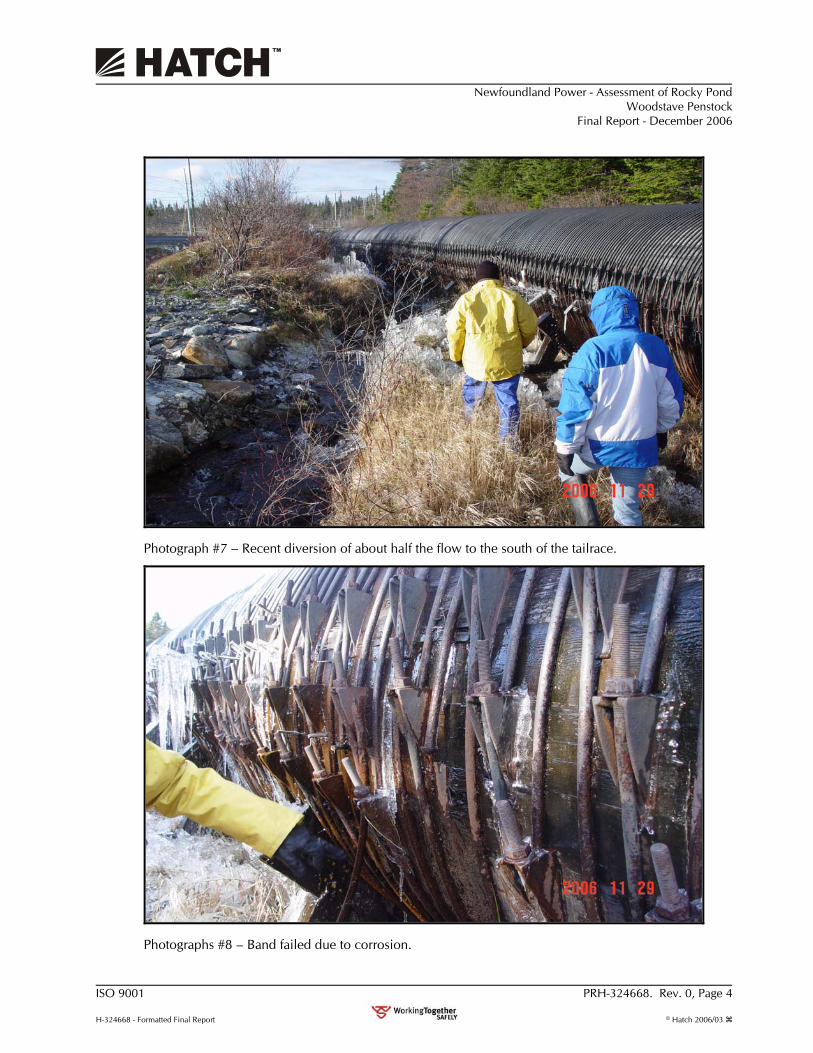
Photograph #7 – Recent diversion of about half the flow to the south of the tailrace.
Photographs #8 – Band failed due to corrosion.
Newfoundland Power - Assessment of Rocky Pond Woodstave Penstock
Final Report - December 2006
ISO 9001 PRH-324668. Rev. 0, Page 5
H-324668 - Formatted Final Report © Hatch 2006/03
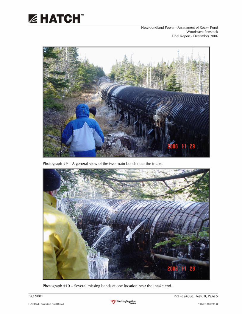
Photograph #9 – A general view of the two main bends near the intake.
Photograph #10 – Several missing bands at one location near the intake end.
Newfoundland Power - Assessment of Rocky Pond Woodstave Penstock
Final Report - December 2006
ISO 9001 PRH-324668. Rev. 0, Page 6
H-324668 - Formatted Final Report © Hatch 2006/03
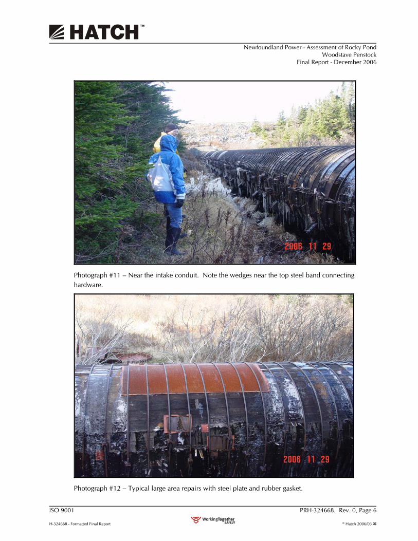
Photograph #11 – Near the intake conduit. Note the wedges near the top steel band connecting hardware.
Photograph #12 – Typical large area repairs with steel plate and rubber gasket.
Newfoundland Power - Assessment of Rocky Pond Woodstave Penstock
Final Report - December 2006
ISO 9001 PRH-324668. Rev. 0, Page 7
H-324668 - Formatted Final Report © Hatch 2006/03
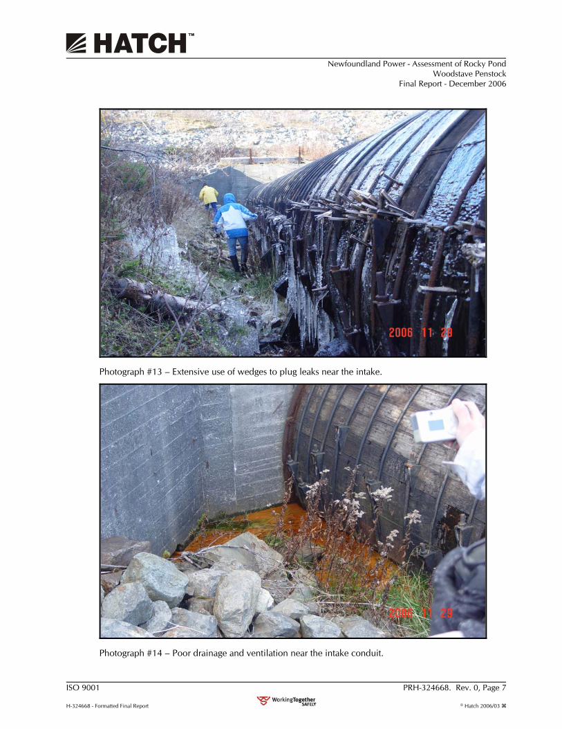
Photograph #13 – Extensive use of wedges to plug leaks near the intake.
Photograph #14 – Poor drainage and ventilation near the intake conduit.
Newfoundland Power - Assessment of Rocky Pond Woodstave Penstock
Final Report - December 2006
ISO 9001 PRH-324668. Rev. 0, Page 8
H-324668 - Formatted Final Report © Hatch 2006/03
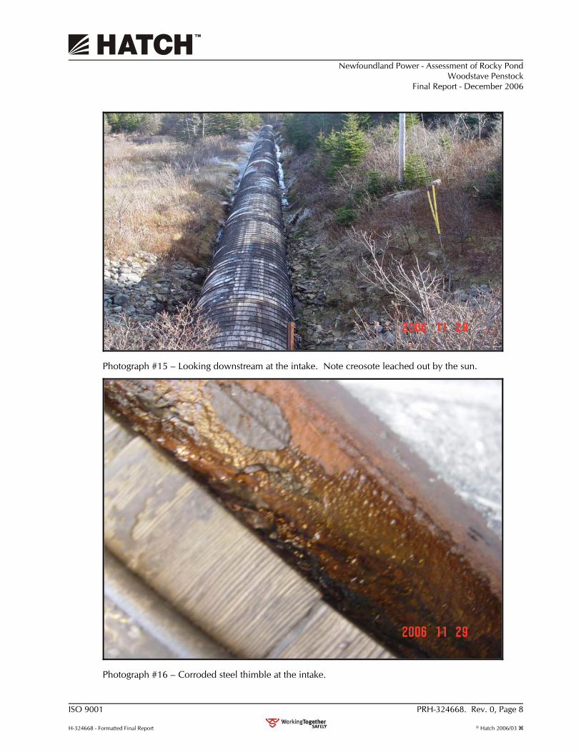
Photograph #15 – Looking downstream at the intake. Note creosote leached out by the sun.
Photograph #16 – Corroded steel thimble at the intake.
Newfoundland Power - Assessment of Rocky Pond Woodstave Penstock
Final Report - December 2006
ISO 9001 PRH-324668. Rev. 0, Page 9
H-324668 - Formatted Final Report © Hatch 2006/03
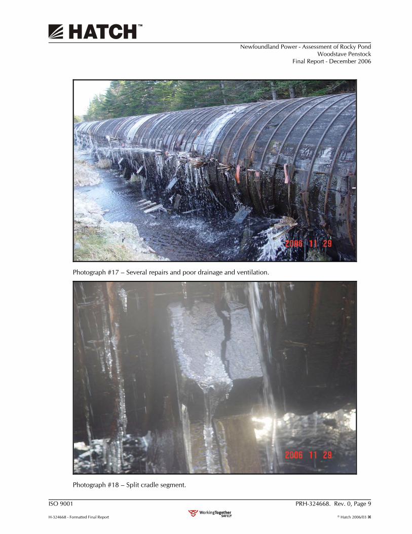
Photograph #17 – Several repairs and poor drainage and ventilation.
Photograph #18 – Split cradle segment.
Newfoundland Power - Assessment of Rocky Pond Woodstave Penstock
Final Report - December 2006
ISO 9001 PRH-324668. Rev. 0, Page 10
H-324668 - Formatted Final Report © Hatch 2006/03
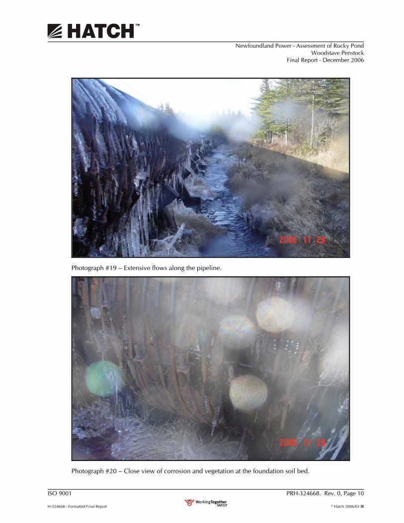
Photograph #19 – Extensive flows along the pipeline.
Photograph #20 – Close view of corrosion and vegetation at the foundation soil bed.
Newfoundland Power - Assessment of Rocky Pond Woodstave Penstock
Final Report - December 2006
ISO 9001 PRH-324668. Rev. 0, Page 11
H-324668 - Formatted Final Report © Hatch 2006/03
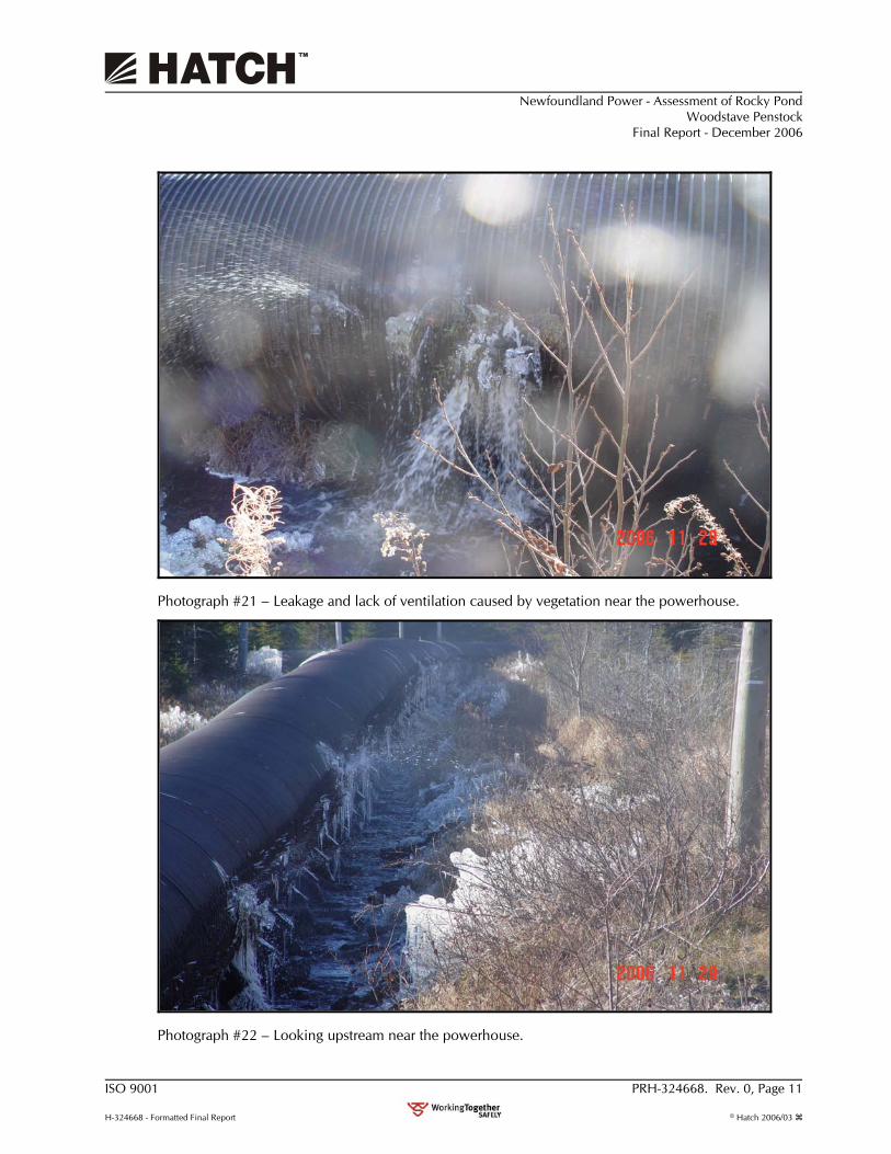
Photograph #21 – Leakage and lack of ventilation caused by vegetation near the powerhouse.
Photograph #22 – Looking upstream near the powerhouse.
Newfoundland Power - Assessment of Rocky Pond Woodstave Penstock
Final Report - December 2006
ISO 9001 PRH-324668. Rev. 0, Page 12
H-324668 - Formatted Final Report © Hatch 2006/03
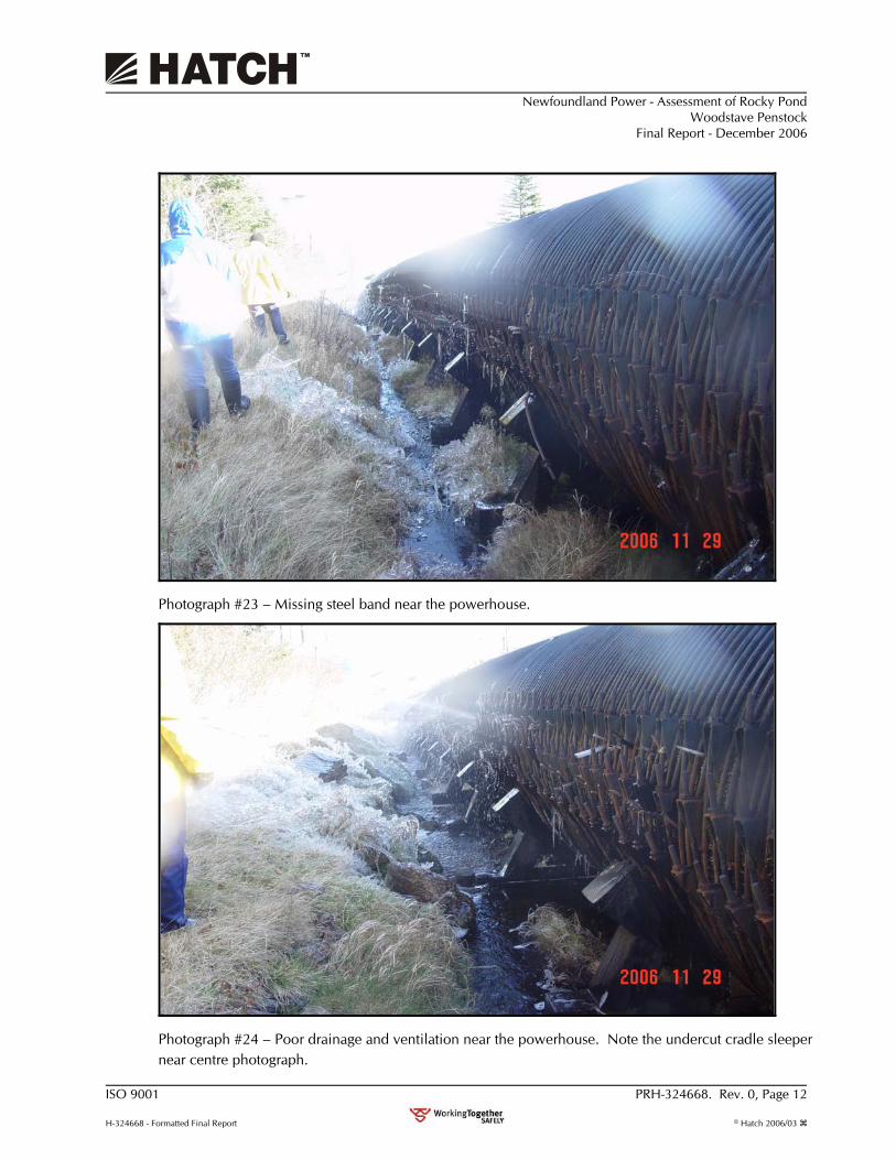
Photograph #23 – Missing steel band near the powerhouse.
Photograph #24 – Poor drainage and ventilation near the powerhouse. Note the undercut cradle sleeper near centre photograph.

Newfoundland Power - Assessment of Rocky Pond Woodstave Penstock
Final Report - December 2006
ISO 9001 PRH-324668. Rev. 0, Page 13
H-324668 - Formatted Final Report © Hatch 2006/03
Photograph #25 – Significant penstock drainage under the repair bay. View is at the downstream of the powerhouse.
Photograph #26 – Typical corroded steel band button head.

Newfoundland Power - Assessment of Rocky Pond Woodstave Penstock
Final Report - December 2006
ISO 9001 PRH-324668. Rev. 0, Page 14
H-324668 - Formatted Final Report © Hatch 2006/03
Photograph #27 – Typical corroded steel band button head.
Photograph #28 – Typical un-corroded steel band button head.

Suite E200, Bally Rou Place, 280 Torbay Rd. St. John's, Newfoundland, Canada A1A 3W8
Tel (709) 754 6933 Fax (709) 754 2717

1.2 Rocky Pond Hydro Plant Refurbishment NP 2009 CBA
Appendix C
Project Schedule
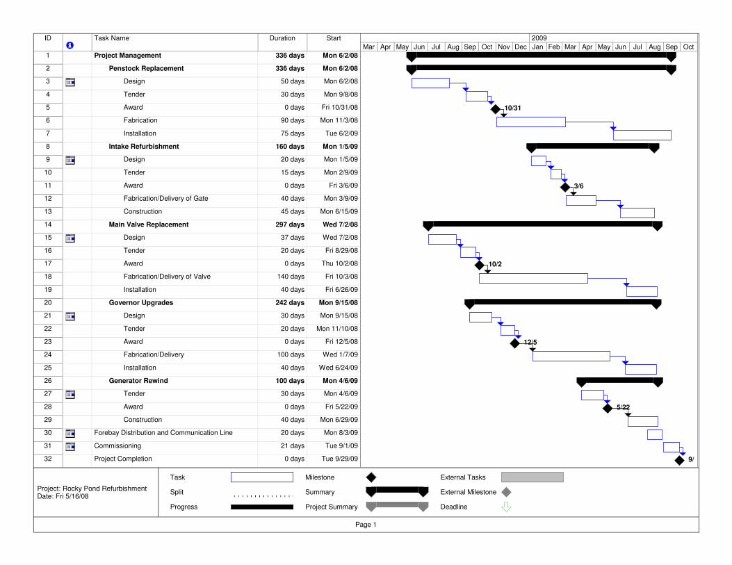
ID Task Name Duration Start
1 Project Management 336 days Mon 6/2/08
2 Penstock Replacement 336 days Mon 6/2/08
3 Design 50 days Mon 6/2/08
4 Tender 30 days Mon 9/8/08
5 Award 0 days Fri 10/31/08
6 Fabrication 90 days Mon 11/3/08
7 Installation 75 days Tue 6/2/09
8 Intake Refurbishment 160 days Mon 1/5/09
9 Design 20 days Mon 1/5/09
10 Tender 15 days Mon 2/9/09
11 Award 0 days Fri 3/6/09
12 Fabrication/Delivery of Gate 40 days Mon 3/9/09
13 Construction 45 days Mon 6/15/09
14 Main Valve Replacement 297 days Wed 7/2/08
15 Design 37 days Wed 7/2/08
16 Tender 20 days Fri 8/29/08
17 Award 0 days Thu 10/2/08
18 Fabrication/Delivery of Valve 140 days Fri 10/3/08
19 Installation 40 days Fri 6/26/09
20 Governor Upgrades 242 days Mon 9/15/08
21 Design 30 days Mon 9/15/08
22 Tender 20 days Mon 11/10/08
23 Award 0 days Fri 12/5/08
24 Fabrication/Delivery 100 days Wed 1/7/09
25 Installation 40 days Wed 6/24/09
26 Generator Rewind 100 days Mon 4/6/09
27 Tender 30 days Mon 4/6/09
28 Award 0 days Fri 5/22/09
29 Construction 40 days Mon 6/29/09
30 Forebay Distribution and Communication Line 20 days Mon 8/3/09
31 Commissioning 21 days Tue 9/1/09
32 Project Completion 0 days Tue 9/29/09
10/31
3/6
10/2
12/5
5/22
9/
Mar Apr May Jun Jul Aug Sep Oct Nov Dec Jan Feb Mar Apr May Jun Jul Aug Sep Oct
2009
Task
Split
Progress
Milestone
Summary
Project Summary
External Tasks
External Milestone
Deadline
Page 1
Project: Rocky Pond RefurbishmentDate: Fri 5/16/08

1.2 Rocky Pond Hydro Plant Refurbishment NP 2009 CBA
Appendix D
Feasibility Analysis
1.2 Rocky Pond Hydro Plant Refurbishment NP 2009 CBA
Table of Contents
Page
1.0 Introduction.......................................................................................................................1 2.0 Capital Costs .....................................................................................................................1 3.0 Operating Costs.................................................................................................................2 4.0 Lost Production.................................................................................................................2 5.0 Financial Analysis.............................................................................................................2 6.0 Recommendation ..............................................................................................................3 Attachment A: Summary of Capital Costs Attachment B: Summary of Operating Costs Attachment C: Calculation of Levelized Cost of Energy

1.2 Rocky Pond Hydro Plant Refurbishment NP 2009 CBA
1
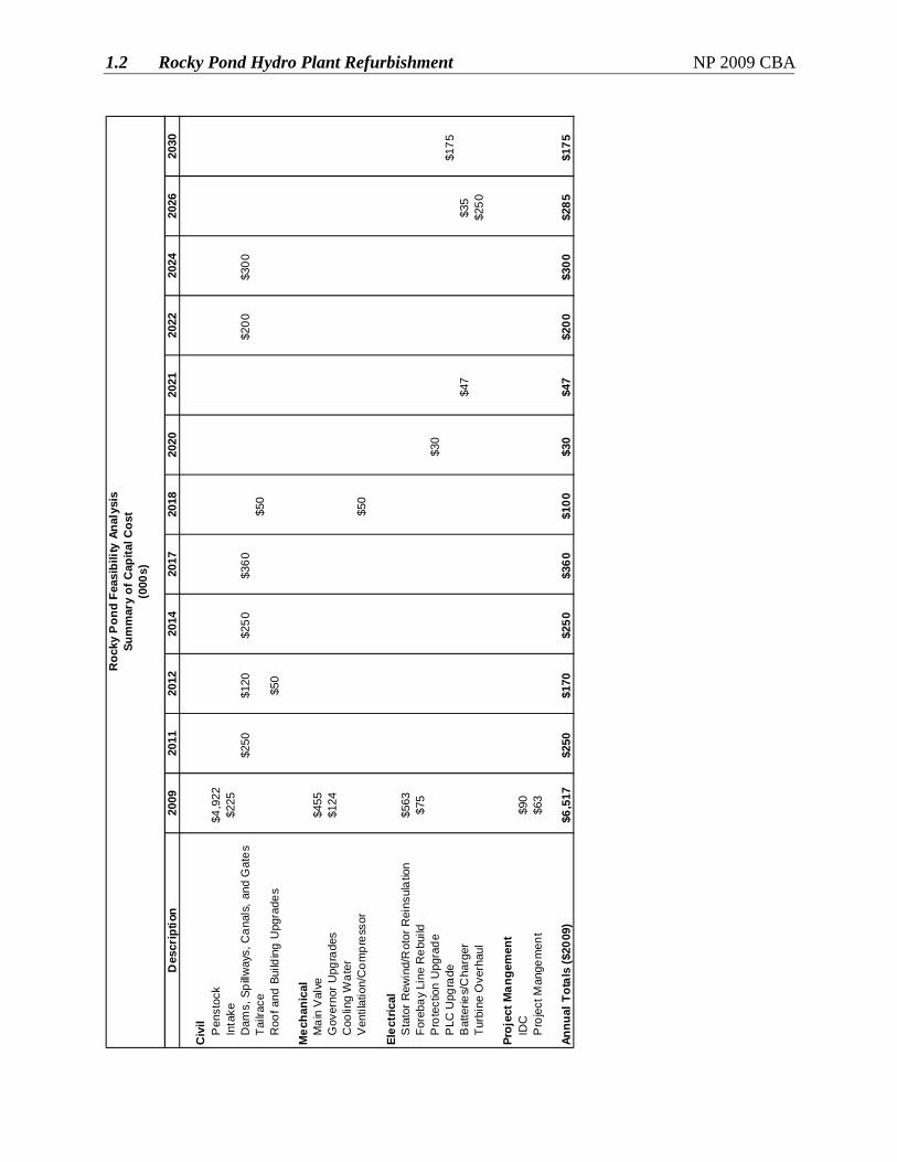
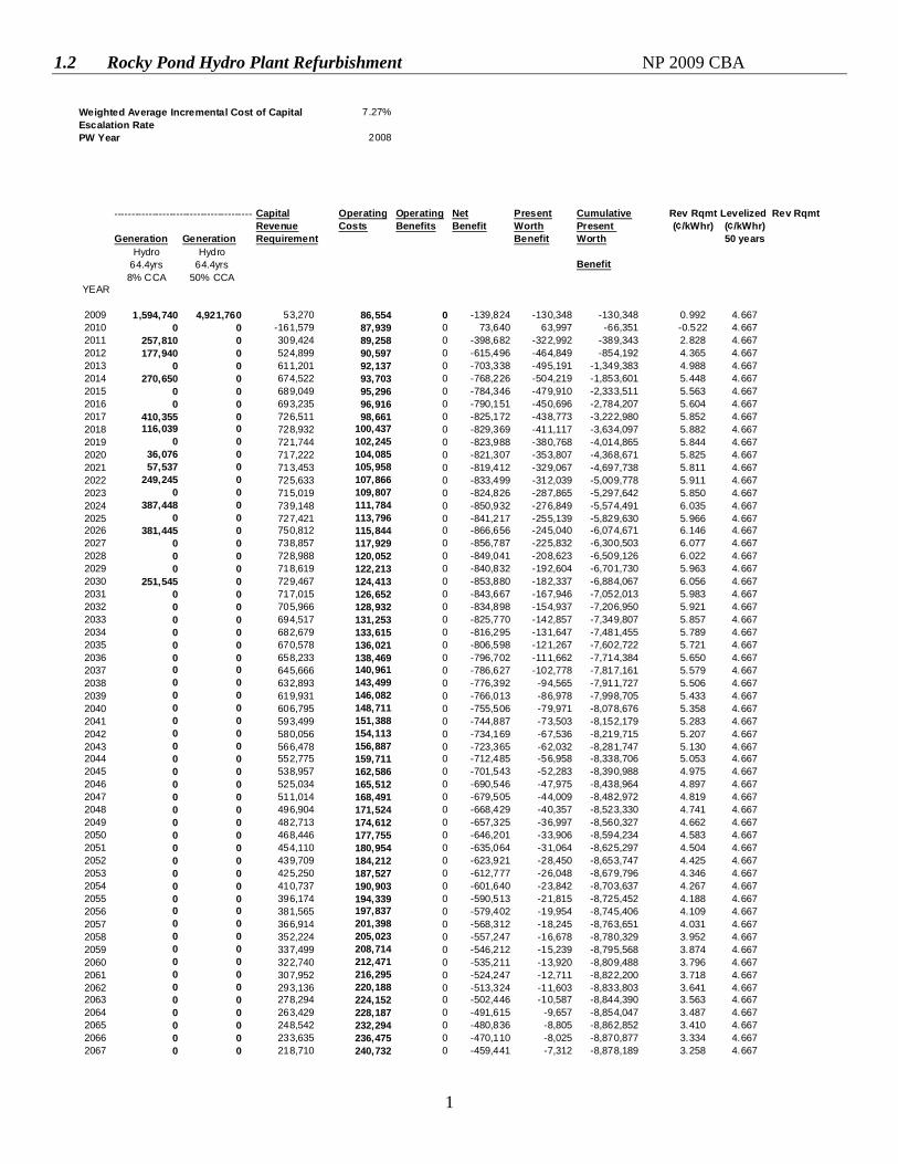
1.0 Introduction This feasibility analysis examines the future viability of Newfoundland Power’s Rocky Pond hydroelectric development. The continued long-term operation of the Rocky Pond hydroelectric development is reliant on the completion of capital improvement in 2009. Planned work includes replacement of the woodstave penstock, refurbishment of the intake structure, a generator rewind, replacement of the main valve, as well as upgrading of the governor controls and rebuilding the forebay distribution and communication line. With substantial investment required in the near-term to permit the continued reliable operation of this plant, an economic analysis of this development was completed. The analysis includes all costs and benefits for the next 50 years to determine the levelized cost of energy from the plant. 2.0 Capital Costs All significant capital expenditures for the hydroelectric development over the next 50 years have been identified. The majority of these expenditures are planned for 2009 with the remaining expenditures planned for future years. The capital expenditures required to maintain the safe and reliable operation of the facilities are summarized in Table 1.
Table 1 Hydroelectric Development
Capital Expenditures
Year Expenditure 2009-2013 $6,937 2014-2018 $710 2019-2023 $277 2024-2028 $585 2029-2031 $175 Total $8,684
The total capital expenditure of all of the projects listed above is $8.7 million. A more comprehensive breakdown of capital costs is provided in Attachment A.
1.2 Rocky Pond Hydro Plant Refurbishment NP 2009 CBA
2
3.0 Operating Costs
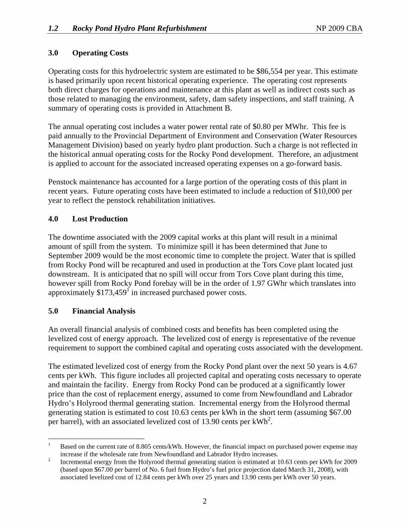
Operating costs for this hydroelectric system are estimated to be $86,554 per year. This estimate is based primarily upon recent historical operating experience. The operating cost represents both direct charges for operations and maintenance at this plant as well as indirect costs such as those related to managing the environment, safety, dam safety inspections, and staff training. A summary of operating costs is provided in Attachment B. The annual operating cost includes a water power rental rate of $0.80 per MWhr. This fee is paid annually to the Provincial Department of Environment and Conservation (Water Resources Management Division) based on yearly hydro plant production. Such a charge is not reflected in the historical annual operating costs for the Rocky Pond development. Therefore, an adjustment is applied to account for the associated increased operating expenses on a go-forward basis. Penstock maintenance has accounted for a large portion of the operating costs of this plant in recent years. Future operating costs have been estimated to include a reduction of $10,000 per year to reflect the penstock rehabilitation initiatives. 4.0 Lost Production The downtime associated with the 2009 capital works at this plant will result in a minimal amount of spill from the system. To minimize spill it has been determined that June to September 2009 would be the most economic time to complete the project. Water that is spilled from Rocky Pond will be recaptured and used in production at the Tors Cove plant located just downstream. It is anticipated that no spill will occur from Tors Cove plant during this time, however spill from Rocky Pond forebay will be in the order of 1.97 GWhr which translates into approximately $173,4591 in increased purchased power costs. 5.0 Financial Analysis An overall financial analysis of combined costs and benefits has been completed using the levelized cost of energy approach. The levelized cost of energy is representative of the revenue requirement to support the combined capital and operating costs associated with the development. The estimated levelized cost of energy from the Rocky Pond plant over the next 50 years is 4.67 cents per kWh. This figure includes all projected capital and operating costs necessary to operate and maintain the facility. Energy from Rocky Pond can be produced at a significantly lower price than the cost of replacement energy, assumed to come from Newfoundland and Labrador Hydro’s Holyrood thermal generating station. Incremental energy from the Holyrood thermal generating station is estimated to cost 10.63 cents per kWh in the short term (assuming $67.00 per barrel), with an associated levelized cost of 13.90 cents per kWh2.
1 Based on the current rate of 8.805 cents/kWh. However, the financial impact on purchased power expense may increase if the wholesale rate from Newfoundland and Labrador Hydro increases. 2 Incremental energy from the Holyrood thermal generating station is estimated at 10.63 cents per kWh for 2009
(based upon $67.00 per barrel of No. 6 fuel from Hydro’s fuel price projection dated March 31, 2008), with associated levelized cost of 12.84 cents per kWh over 25 years and 13.90 cents per kWh over 50 years.

1.2 Rocky Pond Hydro Plant Refurbishment NP 2009 CBA
3
The future capacity benefits of the continued availability of Rocky Pond hydro plant have not been considered in this analysis. If factored into the feasibility analysis, the financial benefit associated with system capacity would further support the viability of continued plant operations. 6.0 Recommendation The results of this feasibility analysis show that the continued operation of the Rocky Pond hydroelectric development is economically viable. Investing in the life extension of facilities at Rocky Pond guarantees the availability of low cost energy to the Province. Otherwise the annual production of 14.1 GWh would be replaced by more expensive energy sources such as new generation or additional production from the Holyrood thermal generating station. Newfoundland Power should proceed with this project in 2009. The project will benefit the Company and its customers by providing least cost, reliable energy for years to come.

1.2 Rocky Pond Hydro Plant Refurbishment NP 2009 CBA
Attachment A Summary of Capital Costs
1.2 Rocky Pond Hydro Plant Refurbishment NP 2009 CBA
Des
crip
tion
2009
2011
2012
2014
2017
2018
2020
2021
2022
2024
2026
2030
Civ
il
Pen
stoc
k$4
,922
In
take
$225
D
ams,
Spi
llway
s, C
anal
s, a
nd G
ates
$250
$120
$250
$360
$200
$300
Ta
ilrac
e$5
0
Roo
f and
Bui
ldin
g U
pgra
des
$50
Mec
hani
cal
M
ain
Val
ve
$455
G
over
nor U
pgra
des
$124
C
oolin
g W
ater
V
entil
atio
n/C
ompr
esso
r$5
0
Elec
tric
al
Sta
tor R
ewin
d/R
otor
Rei
nsul
atio
n$5
63
Fore
bay
Line
Reb
uild
$75
P
rote
ctio
n U
pgra
de$3
0
PLC
Upg
rade
$175
B
atte
ries/
Cha
rger
$4
7$3
5
Turb
ine
Ove
rhau
l$2
50
Proj
ect M
ange
men
t
IDC
$90
P
roje
ct M
ange
men
t$6
3
Annu
al T
otal
s ($
2009
)$6
,517
$250
$170
$250
$360
$100
$30
$47
$200
$300
$285
$175
Roc
ky P
ond
Feas
ibili
ty A
naly
sis
Sum
mar
y of
Cap
ital C
ost
(000
s)

1.2 Rocky Pond Hydro Plant Refurbishment NP 2009 CBA
Attachment B Summary of Operating Costs

1.2 Rocky Pond Hydro Plant Refurbishment NP 2009 CBA
1
Rocky Pond Feasibility Analysis
Summary of Operating Costs
Actual Annual Operating Costs
Year Amount 2003 $63,261 2004 58,359 2005 76,980 2006 105,345 2007 122,426 Average $85,274
5-Year Average Operating Cost 85,274 Water Power Rental Rate1 11,280 Reduced Future Penstock Maintenance - 10,000 Total Forecast Annual Operating Cost $86,554
1 ($0.80/MWh * 14,100 MWh/yr)

1.2 Rocky Pond Hydro Plant Refurbishment NP 2009 CBA
Attachment C Calculation of Levelized Cost of Energy
1.2 Rocky Pond Hydro Plant Refurbishment NP 2009 CBA
1
Weighted Average Incremental Cost of Capital 7.27%Escalation RatePW Year 2008
-----------------------------------------Capital Operating Operating Net Present Cumulative Rev Rqmt Levelized Rev RqmtRevenue Costs Benefits Benefit Worth Present (¢/kWhr) (¢/kWhr)
Generation Generation Requirement Benefit Worth 50 yearsHydro Hydro
64.4yrs 64.4yrs Benefit8% CCA 50% CCA
YEAR
2009 1,594,740 4,921,760 53,270 86,554 0 -139,824 -130,348 -130,348 0.992 4.6672010 0 0 -161,579 87,939 0 73,640 63,997 -66,351 -0.522 4.6672011 257,810 0 309,424 89,258 0 -398,682 -322,992 -389,343 2.828 4.6672012 177,940 0 524,899 90,597 0 -615,496 -464,849 -854,192 4.365 4.6672013 0 0 611,201 92,137 0 -703,338 -495,191 -1,349,383 4.988 4.6672014 270,650 0 674,522 93,703 0 -768,226 -504,219 -1,853,601 5.448 4.6672015 0 0 689,049 95,296 0 -784,346 -479,910 -2,333,511 5.563 4.6672016 0 0 693,235 96,916 0 -790,151 -450,696 -2,784,207 5.604 4.6672017 410,355 0 726,511 98,661 0 -825,172 -438,773 -3,222,980 5.852 4.6672018 116,039 0 728,932 100,437 0 -829,369 -411,117 -3,634,097 5.882 4.6672019 0 0 721,744 102,245 0 -823,988 -380,768 -4,014,865 5.844 4.6672020 36,076 0 717,222 104,085 0 -821,307 -353,807 -4,368,671 5.825 4.6672021 57,537 0 713,453 105,958 0 -819,412 -329,067 -4,697,738 5.811 4.6672022 249,245 0 725,633 107,866 0 -833,499 -312,039 -5,009,778 5.911 4.6672023 0 0 715,019 109,807 0 -824,826 -287,865 -5,297,642 5.850 4.6672024 387,448 0 739,148 111,784 0 -850,932 -276,849 -5,574,491 6.035 4.6672025 0 0 727,421 113,796 0 -841,217 -255,139 -5,829,630 5.966 4.6672026 381,445 0 750,812 115,844 0 -866,656 -245,040 -6,074,671 6.146 4.6672027 0 0 738,857 117,929 0 -856,787 -225,832 -6,300,503 6.077 4.6672028 0 0 728,988 120,052 0 -849,041 -208,623 -6,509,126 6.022 4.6672029 0 0 718,619 122,213 0 -840,832 -192,604 -6,701,730 5.963 4.6672030 251,545 0 729,467 124,413 0 -853,880 -182,337 -6,884,067 6.056 4.6672031 0 0 717,015 126,652 0 -843,667 -167,946 -7,052,013 5.983 4.6672032 0 0 705,966 128,932 0 -834,898 -154,937 -7,206,950 5.921 4.6672033 0 0 694,517 131,253 0 -825,770 -142,857 -7,349,807 5.857 4.6672034 0 0 682,679 133,615 0 -816,295 -131,647 -7,481,455 5.789 4.6672035 0 0 670,578 136,021 0 -806,598 -121,267 -7,602,722 5.721 4.6672036 0 0 658,233 138,469 0 -796,702 -111,662 -7,714,384 5.650 4.6672037 0 0 645,666 140,961 0 -786,627 -102,778 -7,817,161 5.579 4.6672038 0 0 632,893 143,499 0 -776,392 -94,565 -7,911,727 5.506 4.6672039 0 0 619,931 146,082 0 -766,013 -86,978 -7,998,705 5.433 4.6672040 0 0 606,795 148,711 0 -755,506 -79,971 -8,078,676 5.358 4.6672041 0 0 593,499 151,388 0 -744,887 -73,503 -8,152,179 5.283 4.6672042 0 0 580,056 154,113 0 -734,169 -67,536 -8,219,715 5.207 4.6672043 0 0 566,478 156,887 0 -723,365 -62,032 -8,281,747 5.130 4.6672044 0 0 552,775 159,711 0 -712,485 -56,958 -8,338,706 5.053 4.6672045 0 0 538,957 162,586 0 -701,543 -52,283 -8,390,988 4.975 4.6672046 0 0 525,034 165,512 0 -690,546 -47,975 -8,438,964 4.897 4.6672047 0 0 511,014 168,491 0 -679,505 -44,009 -8,482,972 4.819 4.6672048 0 0 496,904 171,524 0 -668,429 -40,357 -8,523,330 4.741 4.6672049 0 0 482,713 174,612 0 -657,325 -36,997 -8,560,327 4.662 4.6672050 0 0 468,446 177,755 0 -646,201 -33,906 -8,594,234 4.583 4.6672051 0 0 454,110 180,954 0 -635,064 -31,064 -8,625,297 4.504 4.6672052 0 0 439,709 184,212 0 -623,921 -28,450 -8,653,747 4.425 4.6672053 0 0 425,250 187,527 0 -612,777 -26,048 -8,679,796 4.346 4.6672054 0 0 410,737 190,903 0 -601,640 -23,842 -8,703,637 4.267 4.6672055 0 0 396,174 194,339 0 -590,513 -21,815 -8,725,452 4.188 4.6672056 0 0 381,565 197,837 0 -579,402 -19,954 -8,745,406 4.109 4.6672057 0 0 366,914 201,398 0 -568,312 -18,245 -8,763,651 4.031 4.6672058 0 0 352,224 205,023 0 -557,247 -16,678 -8,780,329 3.952 4.6672059 0 0 337,499 208,714 0 -546,212 -15,239 -8,795,568 3.874 4.6672060 0 0 322,740 212,471 0 -535,211 -13,920 -8,809,488 3.796 4.6672061 0 0 307,952 216,295 0 -524,247 -12,711 -8,822,200 3.718 4.6672062 0 0 293,136 220,188 0 -513,324 -11,603 -8,833,803 3.641 4.6672063 0 0 278,294 224,152 0 -502,446 -10,587 -8,844,390 3.563 4.6672064 0 0 263,429 228,187 0 -491,615 -9,657 -8,854,047 3.487 4.6672065 0 0 248,542 232,294 0 -480,836 -8,805 -8,862,852 3.410 4.6672066 0 0 233,635 236,475 0 -470,110 -8,025 -8,870,877 3.334 4.6672067 0 0 218,710 240,732 0 -459,441 -7,312 -8,878,189 3.258 4.667
1.2 Rocky Pond Hydro Plant Refurbishment NP 2009 CBA
2
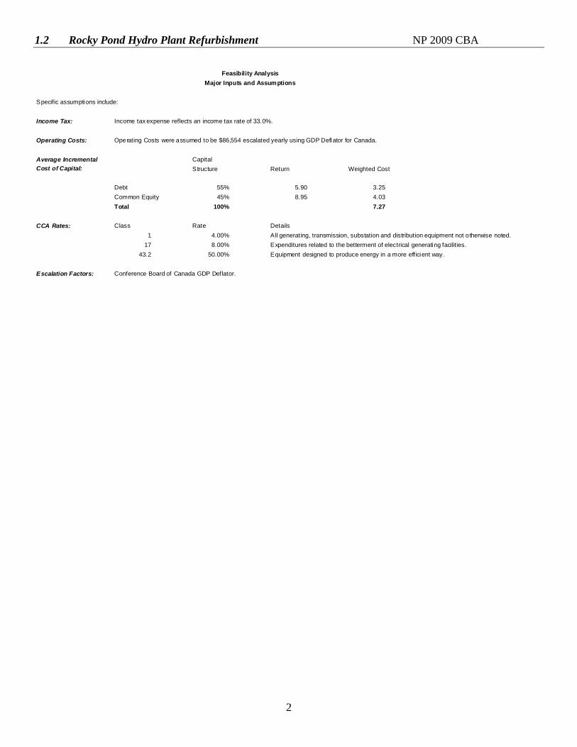
Specific assumptions include:
Income Tax: Income tax expense reflects an income tax rate of 33.0%.
Operating Costs: Operating Costs were assumed to be $86,554 escalated yearly using GDP Deflator for Canada.
Average Incremental Capital Cost of Capital: Structure Return Weighted Cost
Debt 55% 5.90 3.25Common Equity 45% 8.95 4.03Total 100% 7.27
CCA Rates: Class Rate Details1 4.00% All generating, transmission, substation and distribution equipment not o therwise noted.
17 8.00% Expenditures related to the betterment of electrical generating facilities.43.2 50.00% Equipment designed to produce energy in a more efficient way.
Escalation Factors: Conference Board of Canada GDP Deflator.
Feasibility AnalysisMajor Inputs and Assumptions
1.3 Rose B h c h e Hydro Plant Modiflaiions NP 2009 CBA
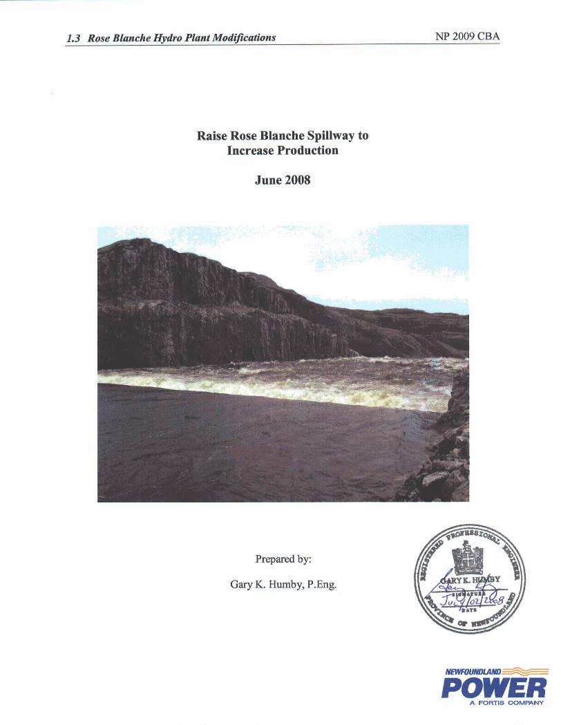
Raise Rose Blanche Spillway to Increase Production
June 2008
Prepared by:
Gary K. Humby, P.Eng.
A FORTIS GOMWNY
1.3 Rose Blanche Hydro Plant Modifications NP 2009 CBA
i
Table of Contents
Page
1.0 Introduction.......................................................................................................................1 2.0 Background.......................................................................................................................1 3.0 Options to Increase Energy Production ............................................................................2 4.0 Feasibility Analysis...........................................................................................................3 5.0 Conclusion ........................................................................................................................3 Appendix A: Rose Blanche Study of Modifications to Increase Energy Appendix B: Photos of Rose Blanche Development Appendix C: Feasibility Analysis
1.3 Rose Blanche Hydro Plant Modifications NP 2009 CBA
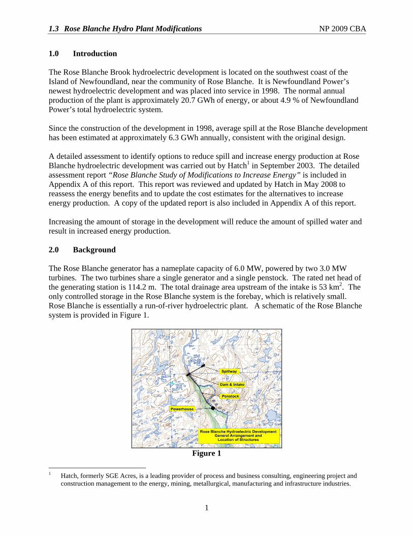
1
1.0 Introduction The Rose Blanche Brook hydroelectric development is located on the southwest coast of the Island of Newfoundland, near the community of Rose Blanche. It is Newfoundland Power’s newest hydroelectric development and was placed into service in 1998. The normal annual production of the plant is approximately 20.7 GWh of energy, or about 4.9 % of Newfoundland Power’s total hydroelectric system. Since the construction of the development in 1998, average spill at the Rose Blanche development has been estimated at approximately 6.3 GWh annually, consistent with the original design. A detailed assessment to identify options to reduce spill and increase energy production at Rose Blanche hydroelectric development was carried out by Hatch1 in September 2003. The detailed assessment report “Rose Blanche Study of Modifications to Increase Energy” is included in Appendix A of this report. This report was reviewed and updated by Hatch in May 2008 to reassess the energy benefits and to update the cost estimates for the alternatives to increase energy production. A copy of the updated report is also included in Appendix A of this report. Increasing the amount of storage in the development will reduce the amount of spilled water and result in increased energy production. 2.0 Background The Rose Blanche generator has a nameplate capacity of 6.0 MW, powered by two 3.0 MW turbines. The two turbines share a single generator and a single penstock. The rated net head of the generating station is 114.2 m. The total drainage area upstream of the intake is 53 km2. The only controlled storage in the Rose Blanche system is the forebay, which is relatively small. Rose Blanche is essentially a run-of-river hydroelectric plant. A schematic of the Rose Blanche system is provided in Figure 1.
Figure 1
1 Hatch, formerly SGE Acres, is a leading provider of process and business consulting, engineering project and
construction management to the energy, mining, metallurgical, manufacturing and infrastructure industries.

1.3 Rose Blanche Hydro Plant Modifications NP 2009 CBA
2
Structures within the Rose Blanche development include the forebay dam, intake and one overflow spillway. The dam is located in a narrow gorge with a maximum height of approximately 30 m and a crest length of 53 m. The intake, located through the left abutment, consists of a reinforced concrete box culvert, steel gate with mechanical lift and a wood frame gatehouse. The spillway is a concrete overflow spillway, located approximately 500 m east of the forebay and is 40 m long. Photos of the system structures are included in Appendix B. Since the construction of the generating station in 1998, average annual spill at Rose Blanche has been estimated to be 6.3 GWh annually. In 2003 Newfoundland Power engaged Hatch to complete a detailed assessment to identify viable options to reduce spill and increase energy production at the Rose Blanche hydroelectric development. The detailed assessment report “Rose Blanche Study of Modifications to Increase Energy” is included in Appendix A of this report. This report was updated by Hatch in May 2008 to reassess the energy benefits and to update the cost estimates for the alternatives proposed. The Hatch report is also included in Appendix A of this report. The detailed assessment includes the identification of alternatives for increasing energy production at Rose Blanche; an estimation of energy benefits associated with each alternative; as well as a review of the relevant flood handing issues, including design flood levels, discharge capacity, freeboard requirements and dam stability. 3.0 Options to Increase Energy Production Production may be increased within a hydroelectric development through either physical changes or operational changes to the system. The least cost physical change to the Rose Blanche system that would directly result in an increase in production includes raising the spillway elevation. Three options considered in raising the spillway elevation include:
• Option 1: Concrete extension on the existing spillway (ogee or rectangular shape); • Option 2: Flashboards anchored to the existing spillway; and • Option 3: Inflatable gate on the existing spillway.
Flashboards can present a hazard if not removed in time to pass floods. The manual stoplog removal process is a hazardous operation, and requires diligent job planning to ensure worker safety is not compromised. External factors, including extreme flood conditions and the inability to access the site may prevent the execution of stoplog removal operations, thus jeopardizing dam safety. The Rose Blanche facility is unstaffed and isolated, and it is not feasible to remove and replace flashboards on a frequent basis. For these reasons, the flashboard option was ruled out as an alternative to increase the height of Rose Blanche spillway. Inflatable gates are more costly than the other alternatives that were evaluated and for this reason were also ruled out as an alternative to increasing the spillway height. It was determined that the most feasible least cost option to increase the height of the spillway at Rose Blanche is a concrete extension. A concrete extension will enhance spill capacity, requires no user intervention during a flood, no power requirements are necessary and since there are no
1.3 Rose Blanche Hydro Plant Modifications NP 2009 CBA
3
moving parts minimal maintenance will be required. Two concrete extension options were evaluated; 0.86 m rectangular concrete extension and a 1.16 m ogee concrete extension. Based on the evaluation of both options it was determined that an ogee shape concrete extension is the most feasible option that will provide the largest incremental increase in annual energy output. The total estimated cost for increasing the height of the existing spillway with an ogee concrete extension is $464,800. The incremental increase in energy output related to raising the spillway is estimated to be 0.9 GWhr for a total annual energy output of 21.6 GWhr. Increasing the height of the spillway will be completed from July to mid August 2009 when reservoir levels are low. During this construction period the plant will remain in operation. The detailed design will be completed in-house and will commence in the first quarter of 2009. 4.0 Feasibility Analysis Appendix C of this report provides a feasibility analysis for raising the height of the existing spillway to increase energy output at Rose Blanche. The results of the feasibility analysis show that raising the height of the existing spillway is economical and will result in an additional 0.9 GWh of energy to the Island Interconnected System. The estimated levelized cost of raising the spillway at Rose Blanche is 4.060 cents per kWh. This energy is lower in cost than energy from sources such as a new hydroelectric development or additional Holyrood thermal generation. Incremental energy from Holyrood thermal generating station is estimated at 10.90 cents per kWh in the short term (assuming $67.00 per barrel), with an associated levelized cost of 13.90 cents per kWh.2 5.0 Conclusion Increasing the height of the spillway at Rose Blanche hydroelectric development will result in an additional 0.9 GWh of energy. The feasibility analysis included in Appendix C verifies the financial viability of completing this project. Based upon the considerations outlined in this report and the attached assessment, the project is recommended to proceed in 2009.
2 Incremental energy from the Holyrood thermal generating station is estimated at 10.63 cents per kWh for 2009
(based upon $67.00 per barrel of No. 6 fuel from Hydro’s fuel price projection dated March 31, 2008), with associated levelized cost of 12.84 cents per kWh over 25 years and 13.90 cents per kWh over 50 years.
1.3 Rose Blanche Hydro Plant Modifications NP 2009 CBA
Appendix A
Rose Blanche Study of Modifications to Increase Energy
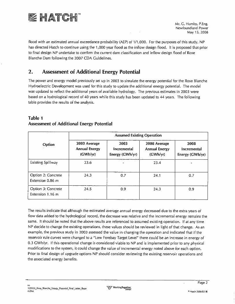
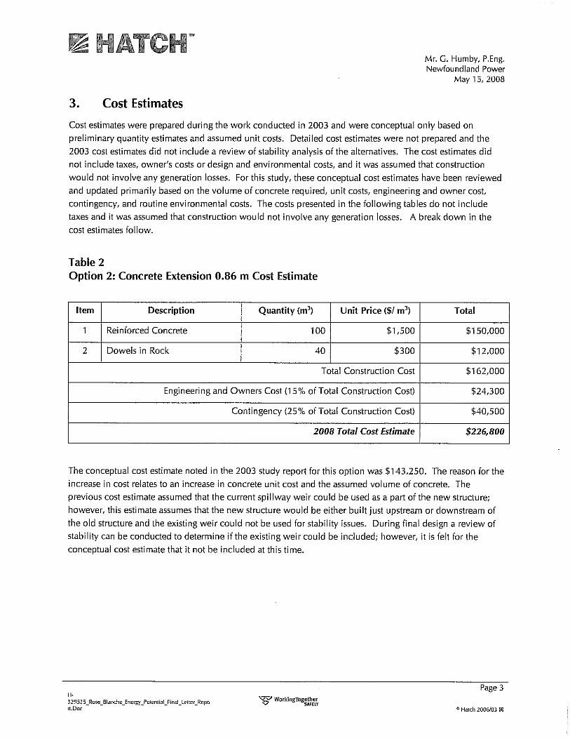
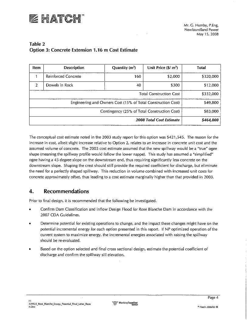
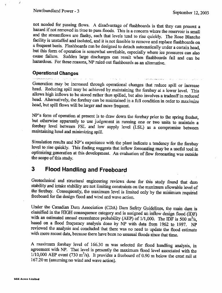
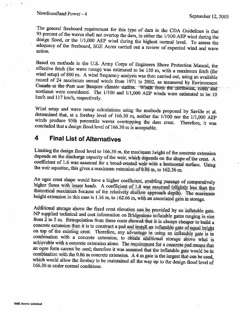

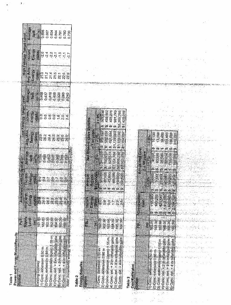
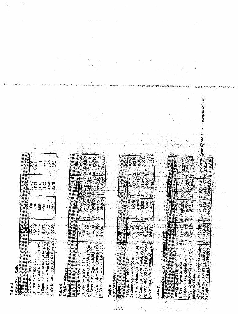
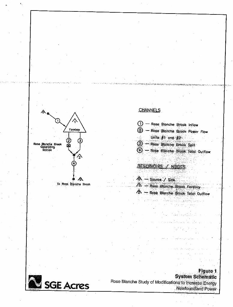
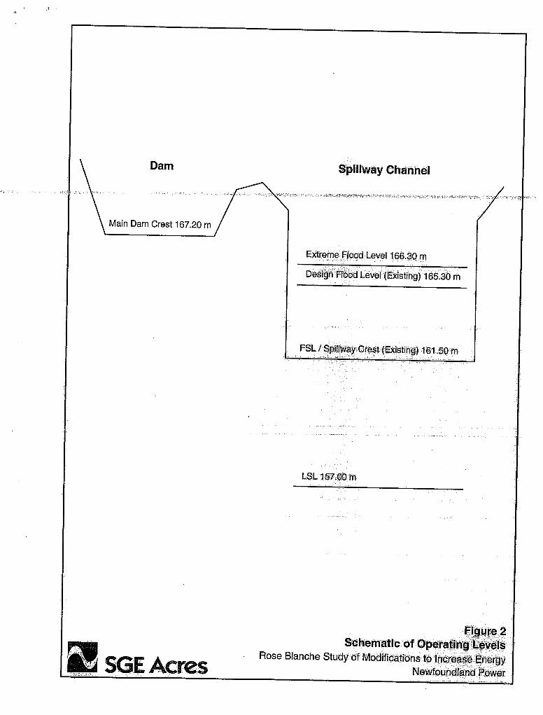
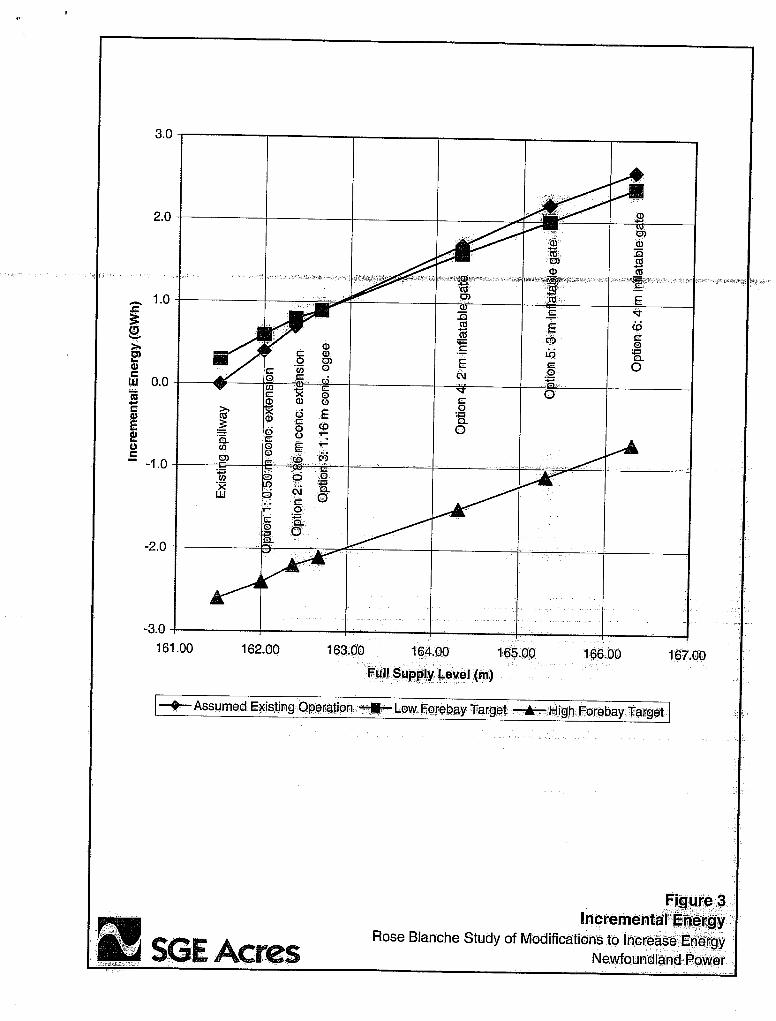
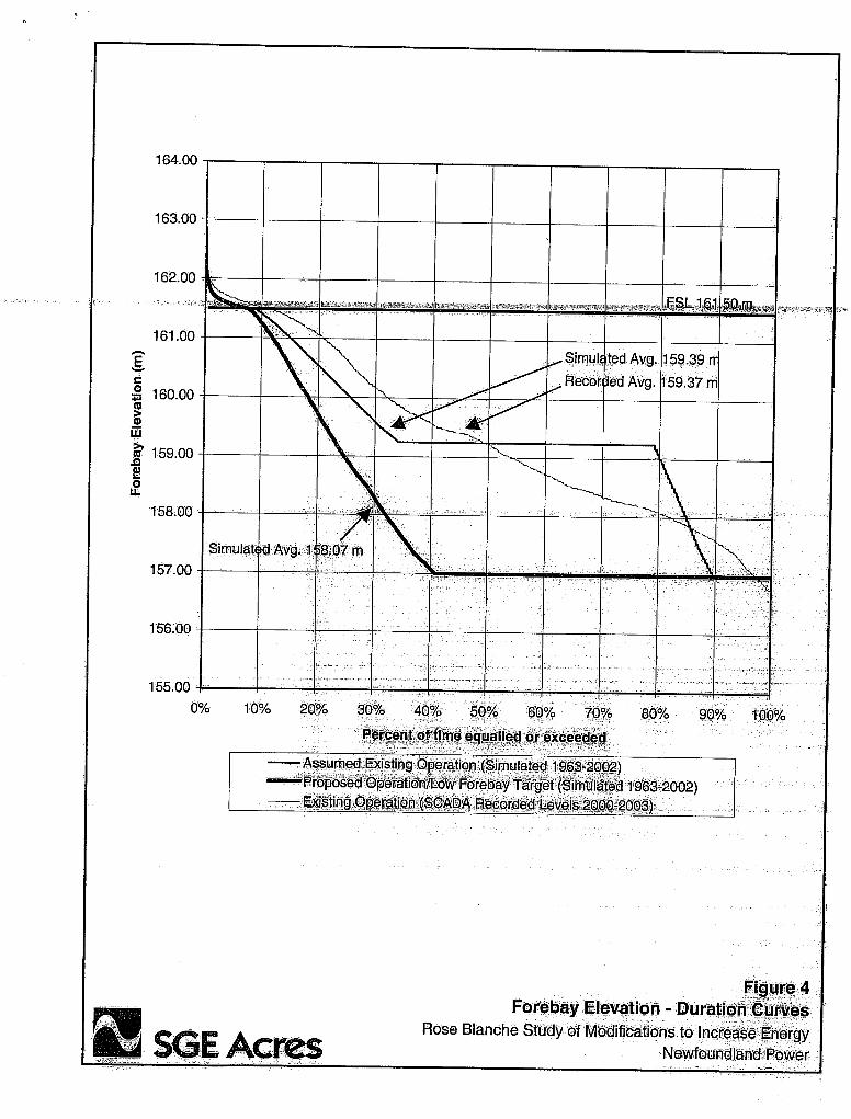
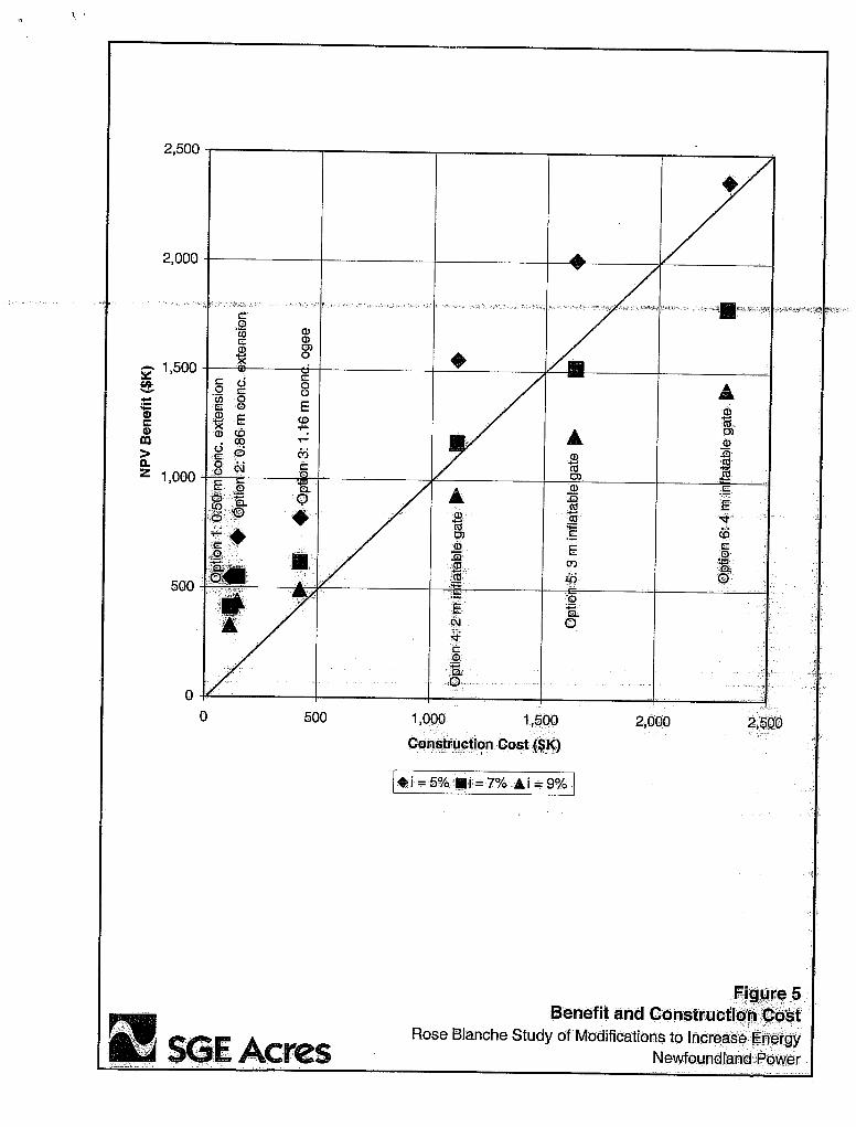
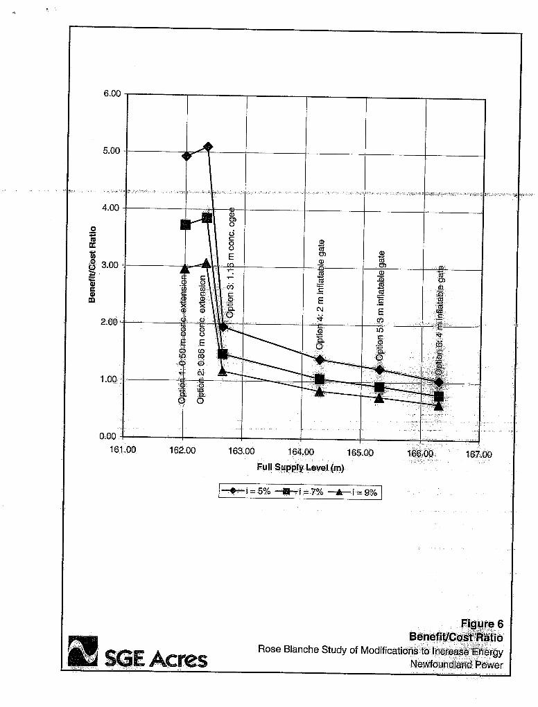
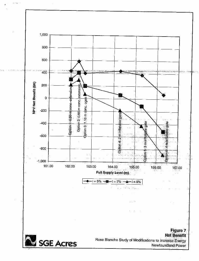
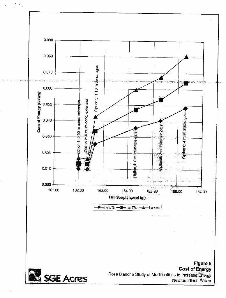
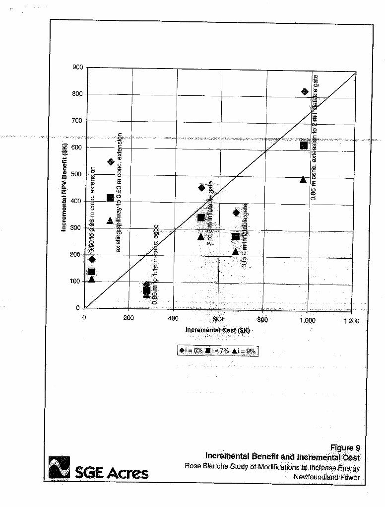
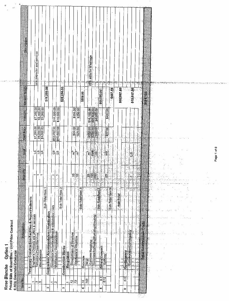
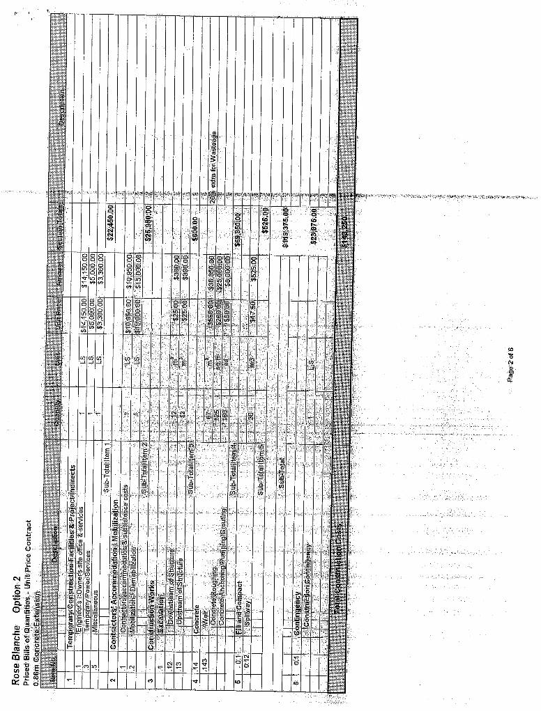
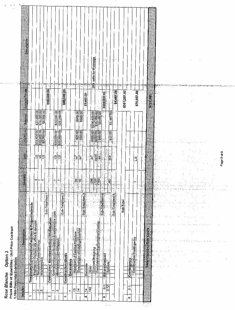
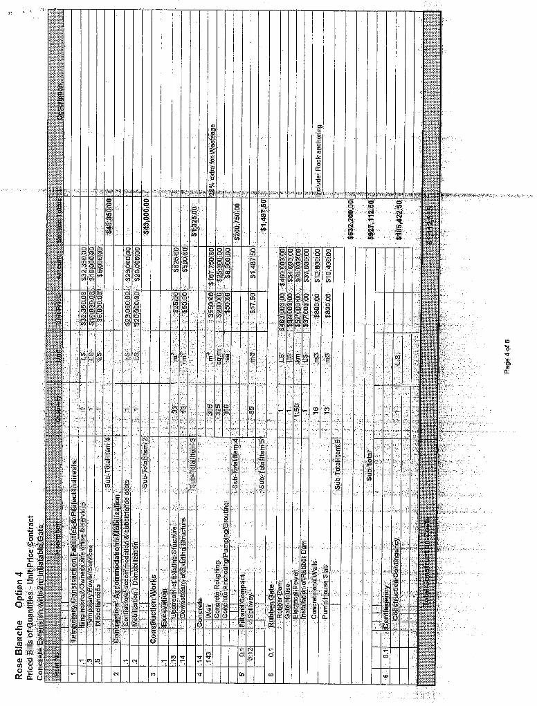
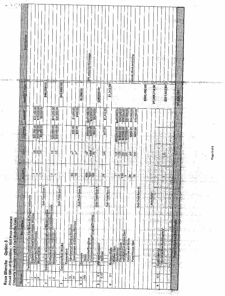
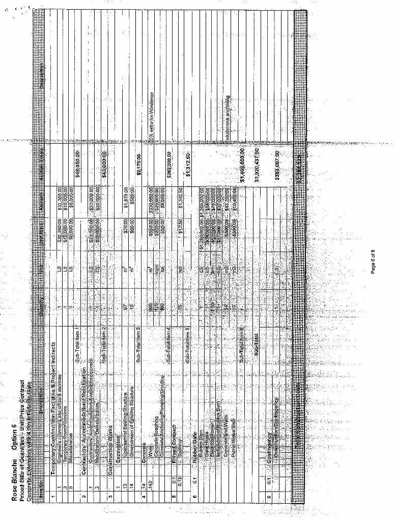

1.3 Rose Blanche Hydro Plant Modifications NP 2009 CBA
Appendix B
Photos of Rose Blanche Development
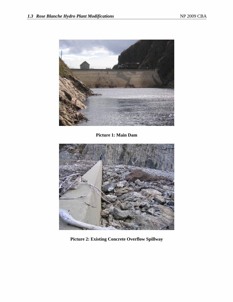
1.3 Rose Blanche Hydro Plant Modifications NP 2009 CBA
Picture 1: Main Dam
Picture 2: Existing Concrete Overflow Spillway
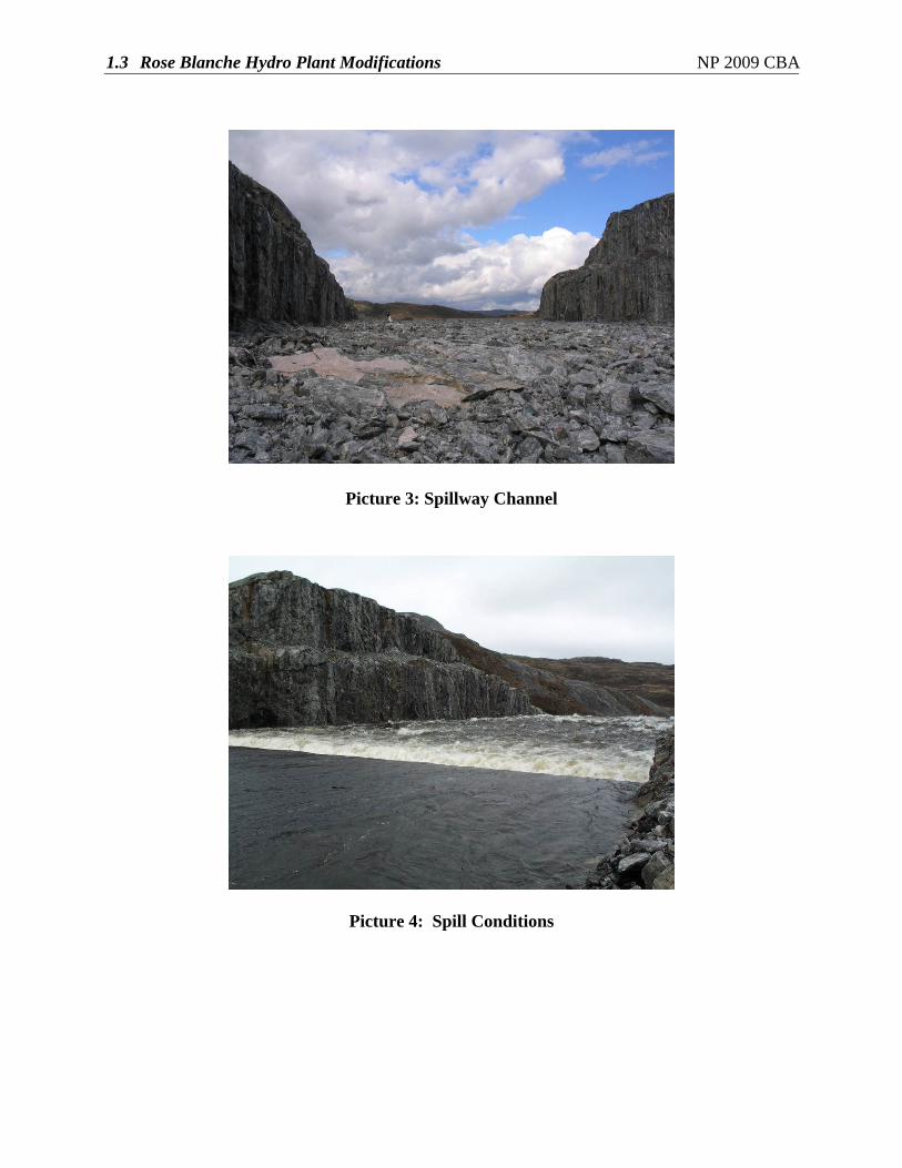
1.3 Rose Blanche Hydro Plant Modifications NP 2009 CBA
Picture 3: Spillway Channel
Picture 4: Spill Conditions

1.3 Rose Blanche Hydro Plant Modifications NP 2009 CBA
Appendix C
Feasibility Analysis
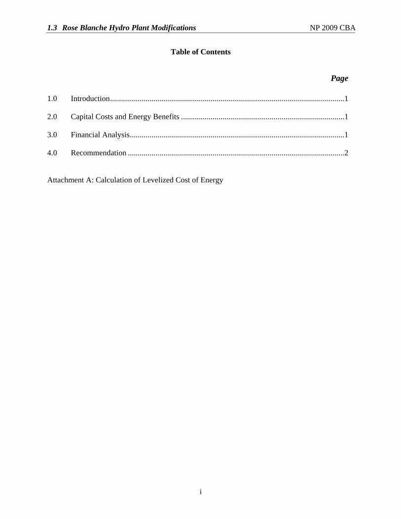
1.3 Rose Blanche Hydro Plant Modifications NP 2009 CBA
i
Table of Contents
Page 1.0 Introduction.......................................................................................................................1 2.0 Capital Costs and Energy Benefits ...................................................................................1 3.0 Financial Analysis.............................................................................................................1 4.0 Recommendation ..............................................................................................................2 Attachment A: Calculation of Levelized Cost of Energy
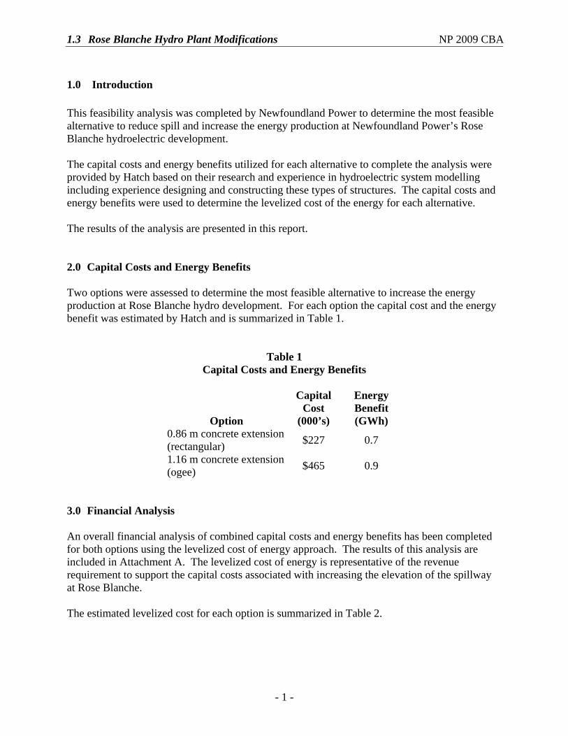
1.3 Rose Blanche Hydro Plant Modifications NP 2009 CBA
- 1 -
1.0 Introduction This feasibility analysis was completed by Newfoundland Power to determine the most feasible alternative to reduce spill and increase the energy production at Newfoundland Power’s Rose Blanche hydroelectric development. The capital costs and energy benefits utilized for each alternative to complete the analysis were provided by Hatch based on their research and experience in hydroelectric system modelling including experience designing and constructing these types of structures. The capital costs and energy benefits were used to determine the levelized cost of the energy for each alternative. The results of the analysis are presented in this report. 2.0 Capital Costs and Energy Benefits
Two options were assessed to determine the most feasible alternative to increase the energy production at Rose Blanche hydro development. For each option the capital cost and the energy benefit was estimated by Hatch and is summarized in Table 1.
Table 1 Capital Costs and Energy Benefits
Option
Capital Cost
(000’s)
Energy Benefit (GWh)
0.86 m concrete extension (rectangular) $227 0.7
1.16 m concrete extension (ogee) $465 0.9
3.0 Financial Analysis
An overall financial analysis of combined capital costs and energy benefits has been completed for both options using the levelized cost of energy approach. The results of this analysis are included in Attachment A. The levelized cost of energy is representative of the revenue requirement to support the capital costs associated with increasing the elevation of the spillway at Rose Blanche. The estimated levelized cost for each option is summarized in Table 2.
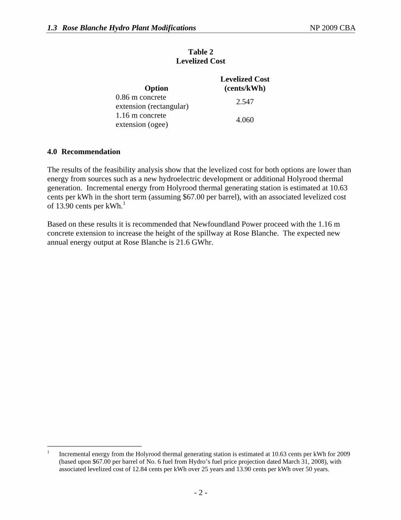
1.3 Rose Blanche Hydro Plant Modifications NP 2009 CBA
- 2 -
Table 2 Levelized Cost
Option Levelized Cost
(cents/kWh) 0.86 m concrete extension (rectangular) 2.547
1.16 m concrete extension (ogee) 4.060
4.0 Recommendation
The results of the feasibility analysis show that the levelized cost for both options are lower than energy from sources such as a new hydroelectric development or additional Holyrood thermal generation. Incremental energy from Holyrood thermal generating station is estimated at 10.63 cents per kWh in the short term (assuming $67.00 per barrel), with an associated levelized cost of 13.90 cents per kWh.1 Based on these results it is recommended that Newfoundland Power proceed with the 1.16 m concrete extension to increase the height of the spillway at Rose Blanche. The expected new annual energy output at Rose Blanche is 21.6 GWhr.
1 Incremental energy from the Holyrood thermal generating station is estimated at 10.63 cents per kWh for 2009
(based upon $67.00 per barrel of No. 6 fuel from Hydro’s fuel price projection dated March 31, 2008), with associated levelized cost of 12.84 cents per kWh over 25 years and 13.90 cents per kWh over 50 years.

1.3 Rose Blanche Hydro Plant Modifications NP 2009 CBA
Attachment A Calculation of Levelized Cost of Energy
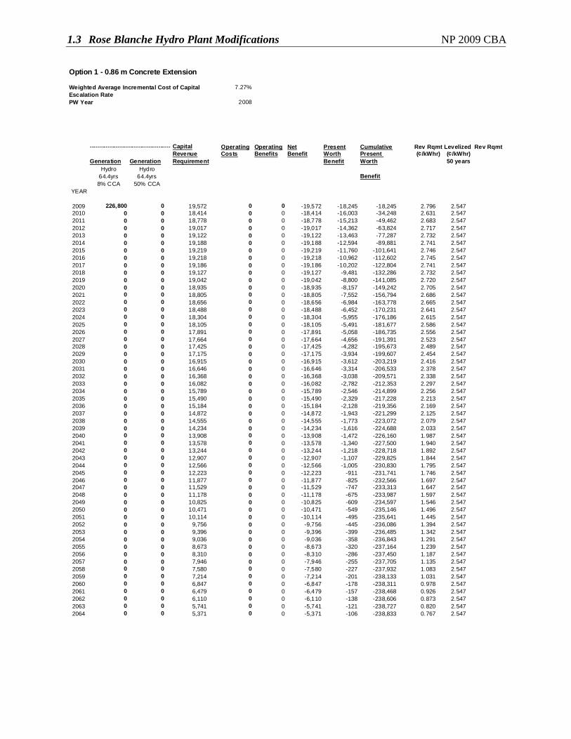
1.3 Rose Blanche Hydro Plant Modifications NP 2009 CBA
Option 1 - 0.86 m Concrete Extension
Weighted Average Incremental Cost of Capital 7.27%Escalation RatePW Year 2008
-----------------------------------------Capital Operating Operating Net Present Cumulative Rev Rqmt Levelized Rev RqmtRevenue Costs Benefits Benefit Worth Present (¢/kWhr) (¢/kWhr)
Generation Generation Requirement Benefit Worth 50 yearsHydro Hydro
64.4yrs 64.4yrs Benefit8% CCA 50% CCA
YEAR
2009 226,800 0 19,572 0 0 -19,572 -18,245 -18,245 2.796 2.5472010 0 0 18,414 0 0 -18,414 -16,003 -34,248 2.631 2.5472011 0 0 18,778 0 0 -18,778 -15,213 -49,462 2.683 2.5472012 0 0 19,017 0 0 -19,017 -14,362 -63,824 2.717 2.5472013 0 0 19,122 0 0 -19,122 -13,463 -77,287 2.732 2.5472014 0 0 19,188 0 0 -19,188 -12,594 -89,881 2.741 2.5472015 0 0 19,219 0 0 -19,219 -11,760 -101,641 2.746 2.5472016 0 0 19,218 0 0 -19,218 -10,962 -112,602 2.745 2.5472017 0 0 19,186 0 0 -19,186 -10,202 -122,804 2.741 2.5472018 0 0 19,127 0 0 -19,127 -9,481 -132,286 2.732 2.5472019 0 0 19,042 0 0 -19,042 -8,800 -141,085 2.720 2.5472020 0 0 18,935 0 0 -18,935 -8,157 -149,242 2.705 2.5472021 0 0 18,805 0 0 -18,805 -7,552 -156,794 2.686 2.5472022 0 0 18,656 0 0 -18,656 -6,984 -163,778 2.665 2.5472023 0 0 18,488 0 0 -18,488 -6,452 -170,231 2.641 2.5472024 0 0 18,304 0 0 -18,304 -5,955 -176,186 2.615 2.5472025 0 0 18,105 0 0 -18,105 -5,491 -181,677 2.586 2.5472026 0 0 17,891 0 0 -17,891 -5,058 -186,735 2.556 2.5472027 0 0 17,664 0 0 -17,664 -4,656 -191,391 2.523 2.5472028 0 0 17,425 0 0 -17,425 -4,282 -195,673 2.489 2.5472029 0 0 17,175 0 0 -17,175 -3,934 -199,607 2.454 2.5472030 0 0 16,915 0 0 -16,915 -3,612 -203,219 2.416 2.5472031 0 0 16,646 0 0 -16,646 -3,314 -206,533 2.378 2.5472032 0 0 16,368 0 0 -16,368 -3,038 -209,571 2.338 2.5472033 0 0 16,082 0 0 -16,082 -2,782 -212,353 2.297 2.5472034 0 0 15,789 0 0 -15,789 -2,546 -214,899 2.256 2.5472035 0 0 15,490 0 0 -15,490 -2,329 -217,228 2.213 2.5472036 0 0 15,184 0 0 -15,184 -2,128 -219,356 2.169 2.5472037 0 0 14,872 0 0 -14,872 -1,943 -221,299 2.125 2.5472038 0 0 14,555 0 0 -14,555 -1,773 -223,072 2.079 2.5472039 0 0 14,234 0 0 -14,234 -1,616 -224,688 2.033 2.5472040 0 0 13,908 0 0 -13,908 -1,472 -226,160 1.987 2.5472041 0 0 13,578 0 0 -13,578 -1,340 -227,500 1.940 2.5472042 0 0 13,244 0 0 -13,244 -1,218 -228,718 1.892 2.5472043 0 0 12,907 0 0 -12,907 -1,107 -229,825 1.844 2.5472044 0 0 12,566 0 0 -12,566 -1,005 -230,830 1.795 2.5472045 0 0 12,223 0 0 -12,223 -911 -231,741 1.746 2.5472046 0 0 11,877 0 0 -11,877 -825 -232,566 1.697 2.5472047 0 0 11,529 0 0 -11,529 -747 -233,313 1.647 2.5472048 0 0 11,178 0 0 -11,178 -675 -233,987 1.597 2.5472049 0 0 10,825 0 0 -10,825 -609 -234,597 1.546 2.5472050 0 0 10,471 0 0 -10,471 -549 -235,146 1.496 2.5472051 0 0 10,114 0 0 -10,114 -495 -235,641 1.445 2.5472052 0 0 9,756 0 0 -9,756 -445 -236,086 1.394 2.5472053 0 0 9,396 0 0 -9,396 -399 -236,485 1.342 2.5472054 0 0 9,036 0 0 -9,036 -358 -236,843 1.291 2.5472055 0 0 8,673 0 0 -8,673 -320 -237,164 1.239 2.5472056 0 0 8,310 0 0 -8,310 -286 -237,450 1.187 2.5472057 0 0 7,946 0 0 -7,946 -255 -237,705 1.135 2.5472058 0 0 7,580 0 0 -7,580 -227 -237,932 1.083 2.5472059 0 0 7,214 0 0 -7,214 -201 -238,133 1.031 2.5472060 0 0 6,847 0 0 -6,847 -178 -238,311 0.978 2.5472061 0 0 6,479 0 0 -6,479 -157 -238,468 0.926 2.5472062 0 0 6,110 0 0 -6,110 -138 -238,606 0.873 2.5472063 0 0 5,741 0 0 -5,741 -121 -238,727 0.820 2.5472064 0 0 5,371 0 0 -5,371 -106 -238,833 0.767 2.547
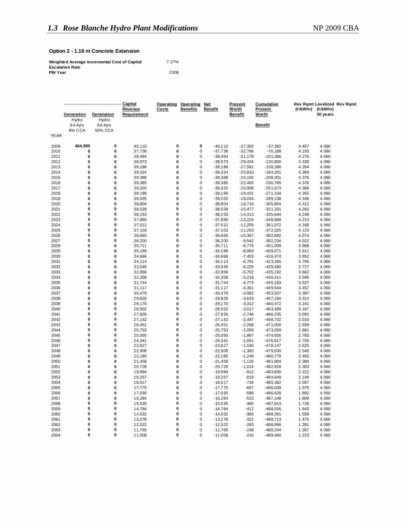
1.3 Rose Blanche Hydro Plant Modifications NP 2009 CBA
Option 2 - 1.16 m Concrete Extension
Weighted Average Incremental Cost of Capital 7.27%Escalation RatePW Year 2008
-----------------------------------------Capital Operating Operating Net Present Cumulative Rev Rqmt Levelized Rev RqmtRevenue Costs Benefits Benefit Worth Present (¢/kWhr) (¢/kWhr)
Generation Generation Requirement Benefit Worth 50 yearsHydro Hydro
64.4yrs 64.4yrs Benefit8% CCA 50% CCA
YEAR
2009 464,800 0 40,110 0 0 -40,110 -37,392 -37,392 4.457 4.0602010 0 0 37,738 0 0 -37,738 -32,796 -70,188 4.193 4.0602011 0 0 38,484 0 0 -38,484 -31,178 -101,366 4.276 4.0602012 0 0 38,973 0 0 -38,973 -29,434 -130,800 4.330 4.0602013 0 0 39,188 0 0 -39,188 -27,591 -158,390 4.354 4.0602014 0 0 39,324 0 0 -39,324 -25,810 -184,201 4.369 4.0602015 0 0 39,388 0 0 -39,388 -24,100 -208,301 4.376 4.0602016 0 0 39,385 0 0 -39,385 -22,465 -230,765 4.376 4.0602017 0 0 39,320 0 0 -39,320 -20,908 -251,673 4.369 4.0602018 0 0 39,199 0 0 -39,199 -19,431 -271,104 4.355 4.0602019 0 0 39,025 0 0 -39,025 -18,034 -289,138 4.336 4.0602020 0 0 38,804 0 0 -38,804 -16,716 -305,854 4.312 4.0602021 0 0 38,539 0 0 -38,539 -15,477 -321,331 4.282 4.0602022 0 0 38,233 0 0 -38,233 -14,313 -335,644 4.248 4.0602023 0 0 37,890 0 0 -37,890 -13,224 -348,868 4.210 4.0602024 0 0 37,512 0 0 -37,512 -12,205 -361,072 4.168 4.0602025 0 0 37,103 0 0 -37,103 -11,253 -372,325 4.123 4.0602026 0 0 36,665 0 0 -36,665 -10,367 -382,692 4.074 4.0602027 0 0 36,200 0 0 -36,200 -9,542 -392,234 4.022 4.0602028 0 0 35,711 0 0 -35,711 -8,775 -401,009 3.968 4.0602029 0 0 35,199 0 0 -35,199 -8,063 -409,071 3.911 4.0602030 0 0 34,666 0 0 -34,666 -7,403 -416,474 3.852 4.0602031 0 0 34,114 0 0 -34,114 -6,791 -423,265 3.790 4.0602032 0 0 33,545 0 0 -33,545 -6,225 -429,490 3.727 4.0602033 0 0 32,959 0 0 -32,959 -5,702 -435,192 3.662 4.0602034 0 0 32,358 0 0 -32,358 -5,219 -440,411 3.595 4.0602035 0 0 31,744 0 0 -31,744 -4,773 -445,183 3.527 4.0602036 0 0 31,117 0 0 -31,117 -4,361 -449,544 3.457 4.0602037 0 0 30,479 0 0 -30,479 -3,982 -453,527 3.387 4.0602038 0 0 29,829 0 0 -29,829 -3,633 -457,160 3.314 4.0602039 0 0 29,170 0 0 -29,170 -3,312 -460,472 3.241 4.0602040 0 0 28,502 0 0 -28,502 -3,017 -463,489 3.167 4.0602041 0 0 27,826 0 0 -27,826 -2,746 -466,235 3.092 4.0602042 0 0 27,142 0 0 -27,142 -2,497 -468,732 3.016 4.0602043 0 0 26,451 0 0 -26,451 -2,268 -471,000 2.939 4.0602044 0 0 25,753 0 0 -25,753 -2,059 -473,059 2.861 4.0602045 0 0 25,050 0 0 -25,050 -1,867 -474,926 2.783 4.0602046 0 0 24,341 0 0 -24,341 -1,691 -476,617 2.705 4.0602047 0 0 23,627 0 0 -23,627 -1,530 -478,147 2.625 4.0602048 0 0 22,908 0 0 -22,908 -1,383 -479,530 2.545 4.0602049 0 0 22,185 0 0 -22,185 -1,249 -480,779 2.465 4.0602050 0 0 21,458 0 0 -21,458 -1,126 -481,904 2.384 4.0602051 0 0 20,728 0 0 -20,728 -1,014 -482,918 2.303 4.0602052 0 0 19,994 0 0 -19,994 -912 -483,830 2.222 4.0602053 0 0 19,257 0 0 -19,257 -819 -484,649 2.140 4.0602054 0 0 18,517 0 0 -18,517 -734 -485,382 2.057 4.0602055 0 0 17,775 0 0 -17,775 -657 -486,039 1.975 4.0602056 0 0 17,030 0 0 -17,030 -586 -486,626 1.892 4.0602057 0 0 16,284 0 0 -16,284 -523 -487,148 1.809 4.0602058 0 0 15,535 0 0 -15,535 -465 -487,613 1.726 4.0602059 0 0 14,784 0 0 -14,784 -412 -488,026 1.643 4.0602060 0 0 14,032 0 0 -14,032 -365 -488,391 1.559 4.0602061 0 0 13,278 0 0 -13,278 -322 -488,713 1.475 4.0602062 0 0 12,522 0 0 -12,522 -283 -488,996 1.391 4.0602063 0 0 11,765 0 0 -11,765 -248 -489,244 1.307 4.0602064 0 0 11,008 0 0 -11,008 -216 -489,460 1.223 4.060
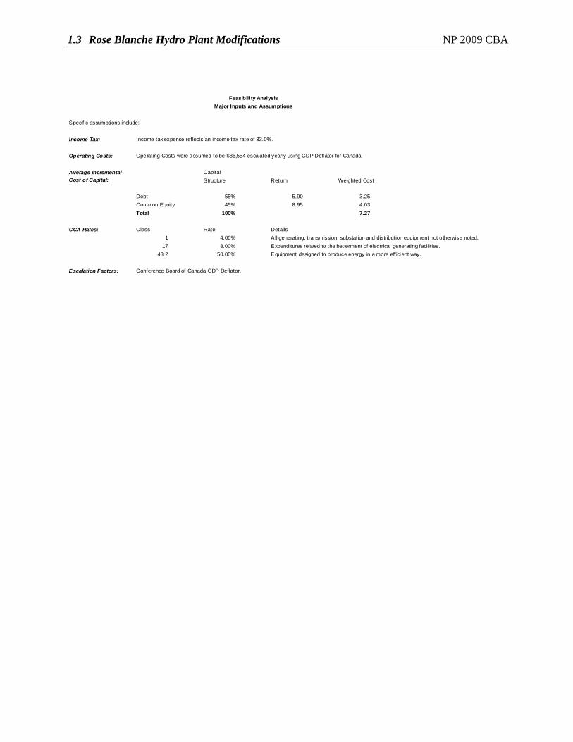
1.3 Rose Blanche Hydro Plant Modifications NP 2009 CBA
Specific assumptions include:
Income Tax: Income tax expense reflects an income tax rate of 33.0%.
Operating Costs: Operating Costs were assumed to be $86,554 escalated yearly using GDP Deflator for Canada.
Average Incremental Capital Cost of Capital: Structure Return Weighted Cost
Debt 55% 5.90 3.25Common Equity 45% 8.95 4.03Total 100% 7.27
CCA Rates: Class Rate Details1 4.00% All generating, transmission, substation and distribution equipment not o therwise noted.
17 8.00% Expenditures related to the betterment of electrical generating facilities.43.2 50.00% Equipment designed to produce energy in a more efficient way.
Escalation Factors: Conference Board of Canada GDP Deflator.
Feasibility AnalysisMajor Inputs and Assumptions