2008 international ansys · pdf file© 2008 ansys, inc. all rights reserved. 1 ansys, inc....
TRANSCRIPT

© 2008 ANSYS, Inc. All rights reserved. 1 ANSYS, Inc. Proprietary
2008 International ANSYS Conference
Guidelines for Obtaining Contact Convergence
Joseph T MetrisinTurbomachineryFlorida Turbine Technologies, Inc.

© 2008 ANSYS, Inc. All rights reserved. 2 ANSYS, Inc. Proprietary
• Incorporated in October 1998• More than 170 people with an average experience base of
>19 years• More than 300 patent applications filed since incorporation
At A Glance … FTT
FTT … A leader in innovation and technical excellence
FTA37F – Two-Spool Turbofan Developed for the Army for
Applications Requiring Performance and Fuel Efficiency
• FTT specializes in gas turbine, turbomachinery, and propulsion components, systems, and engineering for aircraft, space, industrial power, and clean energy
Our Vision:• To be the preferred supplier of turbomachinery
technology and hardware in the world
• Developed the world’s first miniature turbofan for small aircraft requiring high fuel efficiency and performance
• Headquartered in Jupiter, Florida with approximately 200,000 sq ft of facilities for engineering, component & system assembly & test
Turbine Rig Developed, Instrumented and Assembled
for NASA in FTT’s Jupiter, FL Facility
© 2008 ANSYS, Inc. All rights reserved. 3 ANSYS, Inc. Proprietary
Debugging Contact Analyses
• Contact elements are a powerful feature in ANSYS, however the numerous behavior options and inputs can be daunting.
• An estimated 75% of the internal support calls at my company are related to difficulty with contact element convergence.
• Over many years, I have developed a methodical process for troubleshooting and debugging contact analyses.
• These techniques may or may not be unique to gas turbine applications.

© 2008 ANSYS, Inc. All rights reserved. 4 ANSYS, Inc. Proprietary
Typical Turbomachinery Applications
• 2D axisymmetric engine assembly models.– Small Models, many (100+)
contact pairs
• 3D component assembly models– Large Models, few (1-10)
contact pairs

© 2008 ANSYS, Inc. All rights reserved. 5 ANSYS, Inc. Proprietary
[K] [U] = [Fa] For contact problems, [K] is a nonlinear function of [U]
Nonlinear equations written as: [Kit] [ΔUi] = [Fa] – [Fi
nr]
Displacement change between iterations: {Ui+1} = {Ui} + {ΔUi}
[Kit] = Jacobian matrix (tangent matrix).
i = current equilibrium iteration number.
[Fa] = Vector of applied loads.
[Finr] = Vector of restoring loads (opposes the internal nodal loads).
[R] = [Fa] – [Finr] Residual, or out-of-balance force vector.
[R] < 0.001 [Fa] Convergence criteria (Residual must be less than 0.1% of the applied load.
Newton Raphson Method

© 2008 ANSYS, Inc. All rights reserved. 6 ANSYS, Inc. Proprietary
[K] [U] = [Fa] [Kit] [ΔUi] = [Fa] – [Fi
nr] {Ui+1} = {Ui} + {ΔUi}
Newton Raphson Method
1. During equilibrium iterations, ANSYS makes a guess at [ΔUi]
2. [Kit] [ΔUi] is then calculated and ideally, should exactly equal [Fa]
for a converged solution. In reality, there will be some out-of-balance force [Fi
nr]. Consider that if [Kit] is very high, a huge force
is calculated for a bad guess at [ΔUi]
3. The Residual out-of-balance force vector [R] = [Fa] – [Finr] is
calculated and compared to convergence criteria [R] < 0.001 [Fa]
4. At the next iteration, [ΔUi] is adjusted and [R] is recalculated.
5. Iterations continue until convergence is achieved.

© 2008 ANSYS, Inc. All rights reserved. 7 ANSYS, Inc. Proprietary
Understanding the solution output is key to troubleshooting convergence problems: Key terms are:
Understanding Solution Output
Force Convergence Value – This is the residual out-of-balance force vector [R] = [Fa] – [Fi
nr] shown previously.
Criterion – Force convergence criteria [R] < 0.001 [Fa] The force convergence value must be below this value for convergence.
Max DOF Inc – The maximum displacement that occurred on any node in the model during the previous iteration.
Scaled Max DOF Increment – Line search parameter x Max DOF Inc. (This is the displacement vector actually used).
© 2008 ANSYS, Inc. All rights reserved. 8 ANSYS, Inc. Proprietary
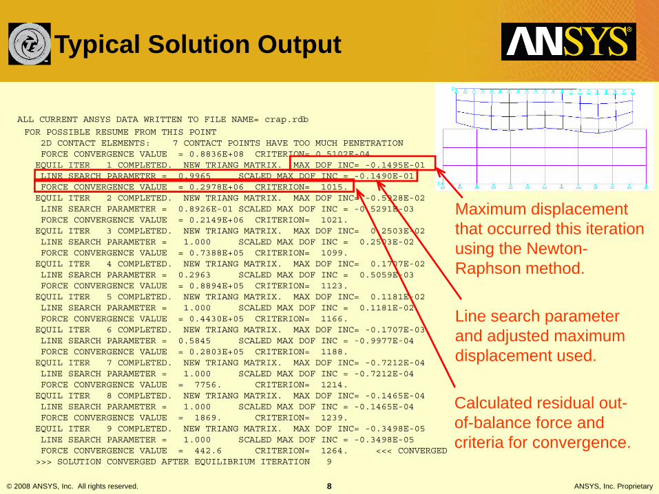
ALL CURRENT ANSYS DATA WRITTEN TO FILE NAME= crap.rdb
FOR POSSIBLE RESUME FROM THIS POINT2D CONTACT ELEMENTS: 7 CONTACT POINTS HAVE TOO MUCH PENETRATIONFORCE CONVERGENCE VALUE = 0.8836E+08 CRITERION= 0.5102E-04EQUIL ITER 1 COMPLETED. NEW TRIANG MATRIX. MAX DOF INC= -0.1495E-01LINE SEARCH PARAMETER = 0.9965 SCALED MAX DOF INC = -0.1490E-01FORCE CONVERGENCE VALUE = 0.2978E+06 CRITERION= 1015.EQUIL ITER 2 COMPLETED. NEW TRIANG MATRIX. MAX DOF INC= -0.5928E-02LINE SEARCH PARAMETER = 0.8926E-01 SCALED MAX DOF INC = -0.5291E-03FORCE CONVERGENCE VALUE = 0.2149E+06 CRITERION= 1021.EQUIL ITER 3 COMPLETED. NEW TRIANG MATRIX. MAX DOF INC= 0.2503E-02LINE SEARCH PARAMETER = 1.000 SCALED MAX DOF INC = 0.2503E-02FORCE CONVERGENCE VALUE = 0.7388E+05 CRITERION= 1099.EQUIL ITER 4 COMPLETED. NEW TRIANG MATRIX. MAX DOF INC= 0.1707E-02LINE SEARCH PARAMETER = 0.2963 SCALED MAX DOF INC = 0.5059E-03FORCE CONVERGENCE VALUE = 0.8894E+05 CRITERION= 1123.EQUIL ITER 5 COMPLETED. NEW TRIANG MATRIX. MAX DOF INC= 0.1181E-02LINE SEARCH PARAMETER = 1.000 SCALED MAX DOF INC = 0.1181E-02FORCE CONVERGENCE VALUE = 0.4430E+05 CRITERION= 1166.EQUIL ITER 6 COMPLETED. NEW TRIANG MATRIX. MAX DOF INC= -0.1707E-03LINE SEARCH PARAMETER = 0.5845 SCALED MAX DOF INC = -0.9977E-04FORCE CONVERGENCE VALUE = 0.2803E+05 CRITERION= 1188.EQUIL ITER 7 COMPLETED. NEW TRIANG MATRIX. MAX DOF INC= -0.7212E-04LINE SEARCH PARAMETER = 1.000 SCALED MAX DOF INC = -0.7212E-04FORCE CONVERGENCE VALUE = 7756. CRITERION= 1214.EQUIL ITER 8 COMPLETED. NEW TRIANG MATRIX. MAX DOF INC= -0.1465E-04LINE SEARCH PARAMETER = 1.000 SCALED MAX DOF INC = -0.1465E-04FORCE CONVERGENCE VALUE = 1869. CRITERION= 1239.EQUIL ITER 9 COMPLETED. NEW TRIANG MATRIX. MAX DOF INC= -0.3498E-05LINE SEARCH PARAMETER = 1.000 SCALED MAX DOF INC = -0.3498E-05FORCE CONVERGENCE VALUE = 442.6 CRITERION= 1264. <<< CONVERGED>>> SOLUTION CONVERGED AFTER EQUILIBRIUM ITERATION 9
Maximum displacement that occurred this iteration using the Newton-Raphson method.
Calculated residual out-of-balance force and criteria for convergence.
Line search parameter and adjusted maximum displacement used.
Typical Solution Output

© 2008 ANSYS, Inc. All rights reserved. 9 ANSYS, Inc. Proprietary
ALL CURRENT ANSYS DATA WRITTEN TO FILE NAME= crap.rdb
FOR POSSIBLE RESUME FROM THIS POINT2D CONTACT ELEMENTS: 7 CONTACT POINTS HAVE TOO MUCH PENETRATIONFORCE CONVERGENCE VALUE = 0.8836E+08 CRITERION= 0.5102E-04EQUIL ITER 1 COMPLETED. NEW TRIANG MATRIX. MAX DOF INC= -0.1495E-01LINE SEARCH PARAMETER = 0.9965 SCALED MAX DOF INC = -0.1490E-01FORCE CONVERGENCE VALUE = 0.2978E+06 CRITERION= 1015.EQUIL ITER 2 COMPLETED. NEW TRIANG MATRIX. MAX DOF INC= -0.5928E-02LINE SEARCH PARAMETER = 0.8926E-01 SCALED MAX DOF INC = -0.5291E-03FORCE CONVERGENCE VALUE = 0.2149E+06 CRITERION= 1021.EQUIL ITER 3 COMPLETED. NEW TRIANG MATRIX. MAX DOF INC= 0.2503E-02LINE SEARCH PARAMETER = 1.000 SCALED MAX DOF INC = 0.2503E-02FORCE CONVERGENCE VALUE = 0.7388E+05 CRITERION= 1099.EQUIL ITER 4 COMPLETED. NEW TRIANG MATRIX. MAX DOF INC= 0.1707E-02LINE SEARCH PARAMETER = 0.2963 SCALED MAX DOF INC = 0.5059E-03FORCE CONVERGENCE VALUE = 0.8894E+05 CRITERION= 1123.EQUIL ITER 5 COMPLETED. NEW TRIANG MATRIX. MAX DOF INC= 0.1181E-02LINE SEARCH PARAMETER = 1.000 SCALED MAX DOF INC = 0.1181E-02FORCE CONVERGENCE VALUE = 0.4430E+05 CRITERION= 1166.EQUIL ITER 6 COMPLETED. NEW TRIANG MATRIX. MAX DOF INC= -0.1707E-03LINE SEARCH PARAMETER = 0.5845 SCALED MAX DOF INC = -0.9977E-04FORCE CONVERGENCE VALUE = 0.2803E+05 CRITERION= 1188.EQUIL ITER 7 COMPLETED. NEW TRIANG MATRIX. MAX DOF INC= -0.7212E-04LINE SEARCH PARAMETER = 1.000 SCALED MAX DOF INC = -0.7212E-04FORCE CONVERGENCE VALUE = 7756. CRITERION= 1214.EQUIL ITER 8 COMPLETED. NEW TRIANG MATRIX. MAX DOF INC= -0.1465E-04LINE SEARCH PARAMETER = 1.000 SCALED MAX DOF INC = -0.1465E-04FORCE CONVERGENCE VALUE = 1869. CRITERION= 1239.EQUIL ITER 9 COMPLETED. NEW TRIANG MATRIX. MAX DOF INC= -0.3498E-05LINE SEARCH PARAMETER = 1.000 SCALED MAX DOF INC = -0.3498E-05FORCE CONVERGENCE VALUE = 442.6 CRITERION= 1264. <<< CONVERGED>>> SOLUTION CONVERGED AFTER EQUILIBRIUM ITERATION 9
Force convergence values are steadily decreasing with little or no oscillation.
Characteristics of a good solution:
Typical Solution Output (continued)
Max DOF values are small and steadily decreasing. Any large values mean that a part has broken free and flown off into space.
© 2008 ANSYS, Inc. All rights reserved. 10 ANSYS, Inc. Proprietary
Basic Contact Modeling Guidelines
• Try to ensure that parts that are initially in contact are built line-on-line.
• If possible, avoid gaps or large interference fits (common for radial pilots). For these cases, set keyopt(9)=4 [ignore geometric fit, use CNOF only, ramp]. This also requires keyopt(12)=4 [no separation, always] and small FKOP (opening stiffness).
• Run CNCHECK and to verify initial contact status.• Always run contact solution in batch mode, not
interactive. This provides a cleaner record of the solution process for debugging purposes.

© 2008 ANSYS, Inc. All rights reserved. 11 ANSYS, Inc. Proprietary
*** NOTE *** CP = 13.190 TIME= 07:00:01Deformable-deformable contact pair identified by real constant set 4and contact element type 6 has been set up.Contact algorithm: Augmented Lagrange methodContact detection at: Gauss integration pointDefault contact stiffness factor FKN 1.0000The resulting contact stiffness 0.15119E+11Default penetration tolerance factor FTOLN 0.10000The resulting penetration tolerance 0.39685E-02Frictionless contact pair is definedUpdate contact stiffness at each iterationAverage contact surface length 0.13228Average contact pair depth 0.39685E-01Default pinball region factor PINB 1.0000The resulting pinball region 0.39685E-01*WARNING*: Initial penetration is included.
*** NOTE *** CP = 13.190 TIME= 07:00:01Max. Initial penetration 2.954468206E-02 was detected between contactelement 138 and target element 129.You may move entire target surface by : x= 1.168198279E-03, y=-2.952157771E-02, z= 0,to reduce initial penetration.
*** WARNING *** CP = 13.190 TIME= 07:00:01The closed gap/penetration may be too large. Increase pinball if it isa true closed gap/penetration. Decrease pinball if it is a false one.****************************************
Summary given for each contact pair:
Real constant values
Lists initial contact gap/interference. Compare this to the pinball distance.
Pay attention to any warnings given.
Element options (keyopts)
Interpreting CNCHECK Summary

© 2008 ANSYS, Inc. All rights reserved. 12 ANSYS, Inc. Proprietary
Consider this model: Displacements on contact part are replaced by forces.
Large initial penetration1300 lbs vertical load
What can go wrong? Example 1

© 2008 ANSYS, Inc. All rights reserved. 13 ANSYS, Inc. Proprietary
ALL CURRENT ANSYS DATA WRITTEN TO FILE NAME= crap.rdbFOR POSSIBLE RESUME FROM THIS POINT
2D CONTACT ELEMENTS: 5 CONTACT POINTS HAVE TOO MUCH PENETRATIONFORCE CONVERGENCE VALUE = 0.3607E+08 CRITERION= 1.556EQUIL ITER 1 COMPLETED. NEW TRIANG MATRIX. MAX DOF INC= 0.2334E-01LINE SEARCH PARAMETER = 0.9970 SCALED MAX DOF INC = 0.2327E-01FORCE CONVERGENCE VALUE = 0.2732E+06 CRITERION= 153.0EQUIL ITER 2 COMPLETED. NEW TRIANG MATRIX. MAX DOF INC= 0.1881E-01LINE SEARCH PARAMETER = 1.000 SCALED MAX DOF INC = 0.1881E-01FORCE CONVERGENCE VALUE = 0.1279E+06 CRITERION= 130.3EQUIL ITER 3 COMPLETED. NEW TRIANG MATRIX. MAX DOF INC= 0.1322E-01LINE SEARCH PARAMETER = 1.000 SCALED MAX DOF INC = 0.1322E-01FORCE CONVERGENCE VALUE = 0.2540E+05 CRITERION= 41.88
*** WARNING *** CP = 16.780 TIME= 10:10:36There are 1 small equation solver pivot terms.
*** ERROR *** CP = 16.780 TIME= 10:10:36The value of UY at node 74 is 2.159160168E+10. It is greater than thecurrent limit of 1000000. This generally indicates rigid body motionas a result of an unconstrained model. Verify that your model isproperly constrained.
*** ERROR *** CP = 16.800 TIME= 10:10:38*** MESSAGE CONTINUATION ---- DIAGNOSTIC INFORMATION ***If one or more parts of the model are held together only by contactverify that the contact surfaces are closed. You can check contactstatus in the SOLUTION module for the converged solutions usingCNCHECK.
>>> DOF LIMIT EXCEEDED. MAX VALUE= 0.2159160E+11 LIMIT= 0.0000000IT MAY BE DUE TO PREDICTOR IS ON.
PREDICTOR IS TURNED OFF FROM THIS POINT ONWARDS.*** LOAD STEP 1 SUBSTEP 1 NOT COMPLETED. CUM ITER = 4*** BEGIN BISECTION NUMBER 1 NEW TIME INCREMENT= 0.50000
ANSYS detects too much penetration.
ANSYS applies huge penalty force [Fi
nr]. Note: Applied load = 1300 lbs.
Excessive penalty force pushes contact part out of orbit.
ANSYS tries to correct by bisection (applied load is cut in half, and ANSYS tries again) -- Problem continues with multiple bisections, never converges.
What can go wrong? Example 1

© 2008 ANSYS, Inc. All rights reserved. 14 ANSYS, Inc. Proprietary
Example 1, Lesson Learned
• Ensure parts are initially in contact, but not excessively. • In this case, the use of enforced displacements instead of
forces will converged nicely. • What if I don’t want enforced displacements? • Try using contact damping (Real constant 11 – FKOP)
with standard contact. Ramp over several (5+) load steps.
• Try using keyopt(9)=4 to ramp interference fit over several load steps. Note: This also requires the use of keyopt(12)=4 – No separation (always) with a small opening stiffness (FKOP)
• Run first load step with enforced displacements to obtain convergence, then run second load step with enforced displacements removed, and desired forced applied.
© 2008 ANSYS, Inc. All rights reserved. 15 ANSYS, Inc. Proprietary
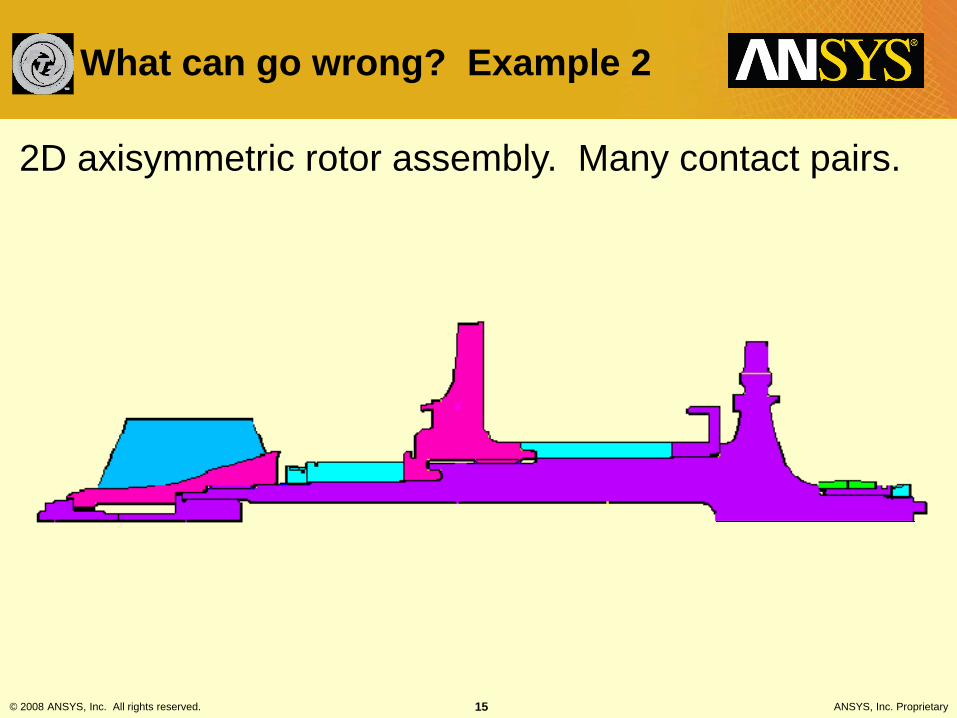
2D axisymmetric rotor assembly. Many contact pairs.
What can go wrong? Example 2
© 2008 ANSYS, Inc. All rights reserved. 16 ANSYS, Inc. Proprietary
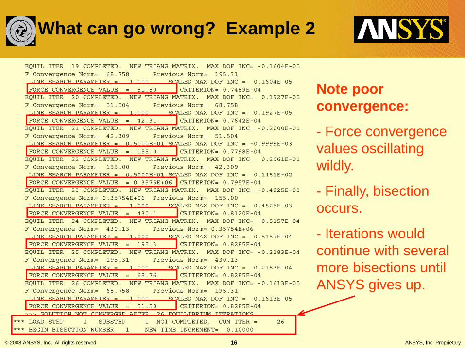
EQUIL ITER 19 COMPLETED. NEW TRIANG MATRIX. MAX DOF INC= -0.1604E-05F Convergence Norm= 68.758 Previous Norm= 195.31LINE SEARCH PARAMETER = 1.000 SCALED MAX DOF INC = -0.1604E-05FORCE CONVERGENCE VALUE = 51.50 CRITERION= 0.7489E-04EQUIL ITER 20 COMPLETED. NEW TRIANG MATRIX. MAX DOF INC= 0.1927E-05F Convergence Norm= 51.504 Previous Norm= 68.758LINE SEARCH PARAMETER = 1.000 SCALED MAX DOF INC = 0.1927E-05FORCE CONVERGENCE VALUE = 42.31 CRITERION= 0.7642E-04EQUIL ITER 21 COMPLETED. NEW TRIANG MATRIX. MAX DOF INC= -0.2000E-01F Convergence Norm= 42.309 Previous Norm= 51.504LINE SEARCH PARAMETER = 0.5000E-01 SCALED MAX DOF INC = -0.9999E-03FORCE CONVERGENCE VALUE = 155.0 CRITERION= 0.7798E-04EQUIL ITER 22 COMPLETED. NEW TRIANG MATRIX. MAX DOF INC= 0.2961E-01F Convergence Norm= 155.00 Previous Norm= 42.309LINE SEARCH PARAMETER = 0.5000E-01 SCALED MAX DOF INC = 0.1481E-02FORCE CONVERGENCE VALUE = 0.3575E+06 CRITERION= 0.7957E-04EQUIL ITER 23 COMPLETED. NEW TRIANG MATRIX. MAX DOF INC= -0.4825E-03F Convergence Norm= 0.35754E+06 Previous Norm= 155.00LINE SEARCH PARAMETER = 1.000 SCALED MAX DOF INC = -0.4825E-03FORCE CONVERGENCE VALUE = 430.1 CRITERION= 0.8120E-04EQUIL ITER 24 COMPLETED. NEW TRIANG MATRIX. MAX DOF INC= -0.5157E-04F Convergence Norm= 430.13 Previous Norm= 0.35754E+06LINE SEARCH PARAMETER = 1.000 SCALED MAX DOF INC = -0.5157E-04FORCE CONVERGENCE VALUE = 195.3 CRITERION= 0.8285E-04EQUIL ITER 25 COMPLETED. NEW TRIANG MATRIX. MAX DOF INC= -0.2183E-04F Convergence Norm= 195.31 Previous Norm= 430.13LINE SEARCH PARAMETER = 1.000 SCALED MAX DOF INC = -0.2183E-04FORCE CONVERGENCE VALUE = 68.76 CRITERION= 0.8285E-04EQUIL ITER 26 COMPLETED. NEW TRIANG MATRIX. MAX DOF INC= -0.1613E-05F Convergence Norm= 68.758 Previous Norm= 195.31LINE SEARCH PARAMETER = 1.000 SCALED MAX DOF INC = -0.1613E-05FORCE CONVERGENCE VALUE = 51.50 CRITERION= 0.8285E-04>>> SOLUTION NOT CONVERGED AFTER 26 EQUILIBRIUM ITERATIONS
*** LOAD STEP 1 SUBSTEP 1 NOT COMPLETED. CUM ITER = 26*** BEGIN BISECTION NUMBER 1 NEW TIME INCREMENT= 0.10000
What can go wrong? Example 2
Note poor convergence:
- Force convergence values oscillating wildly.
- Finally, bisection occurs.
- Iterations would continue with several more bisections until ANSYS gives up.
© 2008 ANSYS, Inc. All rights reserved. 17 ANSYS, Inc. Proprietary
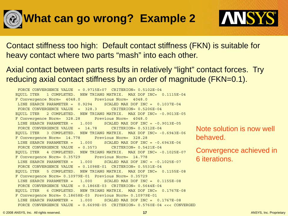
FORCE CONVERGENCE VALUE = 0.9715E+07 CRITERION= 0.5102E-04EQUIL ITER 1 COMPLETED. NEW TRIANG MATRIX. MAX DOF INC= 0.1115E-04F Convergence Norm= 4048.0 Previous Norm= 4048.0LINE SEARCH PARAMETER = 0.9294 SCALED MAX DOF INC = 0.1037E-04FORCE CONVERGENCE VALUE = 328.3 CRITERION= 0.5206E-04EQUIL ITER 2 COMPLETED. NEW TRIANG MATRIX. MAX DOF INC= -0.9013E-05F Convergence Norm= 328.28 Previous Norm= 4048.0LINE SEARCH PARAMETER = 1.000 SCALED MAX DOF INC = -0.9013E-05FORCE CONVERGENCE VALUE = 14.78 CRITERION= 0.5312E-04EQUIL ITER 3 COMPLETED. NEW TRIANG MATRIX. MAX DOF INC= -0.6943E-06F Convergence Norm= 14.778 Previous Norm= 328.28LINE SEARCH PARAMETER = 1.000 SCALED MAX DOF INC = -0.6943E-06FORCE CONVERGENCE VALUE = 0.3573 CRITERION= 0.5421E-04EQUIL ITER 4 COMPLETED. NEW TRIANG MATRIX. MAX DOF INC= -0.1025E-07F Convergence Norm= 0.35729 Previous Norm= 14.778LINE SEARCH PARAMETER = 1.000 SCALED MAX DOF INC = -0.1025E-07FORCE CONVERGENCE VALUE = 0.1098E-01 CRITERION= 0.5531E-04EQUIL ITER 5 COMPLETED. NEW TRIANG MATRIX. MAX DOF INC= 0.1155E-08F Convergence Norm= 0.10979E-01 Previous Norm= 0.35729LINE SEARCH PARAMETER = 1.000 SCALED MAX DOF INC = 0.1155E-08FORCE CONVERGENCE VALUE = 0.1866E-03 CRITERION= 0.5644E-04EQUIL ITER 6 COMPLETED. NEW TRIANG MATRIX. MAX DOF INC= 0.1767E-08F Convergence Norm= 0.18658E-03 Previous Norm= 0.10979E-01LINE SEARCH PARAMETER = 1.000 SCALED MAX DOF INC = 0.1767E-08FORCE CONVERGENCE VALUE = 0.6699E-05 CRITERION= 0.5760E-04 <<< CONVERGED
Note solution is now well behaved.
Convergence achieved in 6 iterations.
What can go wrong? Example 2
Contact stiffness too high: Default contact stiffness (FKN) is suitable for heavy contact where two parts “mash” into each other.
Axial contact between parts results in relatively “light” contact forces. Try reducing axial contact stiffness by an order of magnitude (FKN=0.1).

© 2008 ANSYS, Inc. All rights reserved. 18 ANSYS, Inc. Proprietary
Lessons Learned: Example 2
• When contact is maintained, but residual out-of-balance force cannot be reduced to convergence value, try reducing FKN by 10x or more.
• Reducing FKN usually aids convergence and reduces number of equilibrium iterations.
• Use caution and monitor resulting contact surface penetration.
• Use caution when simulating press-fits such as radial snaps because any penetration will relieve a certain amount of preload.

© 2008 ANSYS, Inc. All rights reserved. 19 ANSYS, Inc. Proprietary
Note: Parts appear to be touching, but……
Gear tooth analysis:
What can go wrong? Example 3

© 2008 ANSYS, Inc. All rights reserved. 20 ANSYS, Inc. Proprietary
Contact element info printed at beginning of solution (one set of info for each pair):*** NOTE *** CP = 15.200 TIME= 13:59:38Deformable-deformable contact pair identified by real constant set 12and contact element type 4 has been set up.Contact algorithm: Augmented Lagrange methodContact detection at: Gauss integration pointContact stiffness factor FKN 1.0000The resulting contact stiffness 0.11462E+12Default penetration tolerance factor FTOLN 0.10000The resulting penetration tolerance 0.49138E-03Frictionless contact pair is definedAverage contact surface length 0.48595E-02Average contact pair depth 0.49138E-02Default pinball region factor PINB 1.0000The resulting pinball region 0.49138E-02*WARNING*: Initial penetration is included.
*** NOTE *** CP = 15.200 TIME= 13:59:38Min. Initial gap 9.94310515E-07 was detected between contact element11806 and target element 11771.You may move entire target surface by: x= -9.017547135E-07, y=4.189174583E-07, z= 0, to bring it in contact.****************************************
Contact pair is initially open by very small amount.
Surfaces are within the default pinball region though.
Solution fails with rigid body motion.
What can go wrong? Example 3
Gear tooth analysis:
© 2008 ANSYS, Inc. All rights reserved. 21 ANSYS, Inc. Proprietary
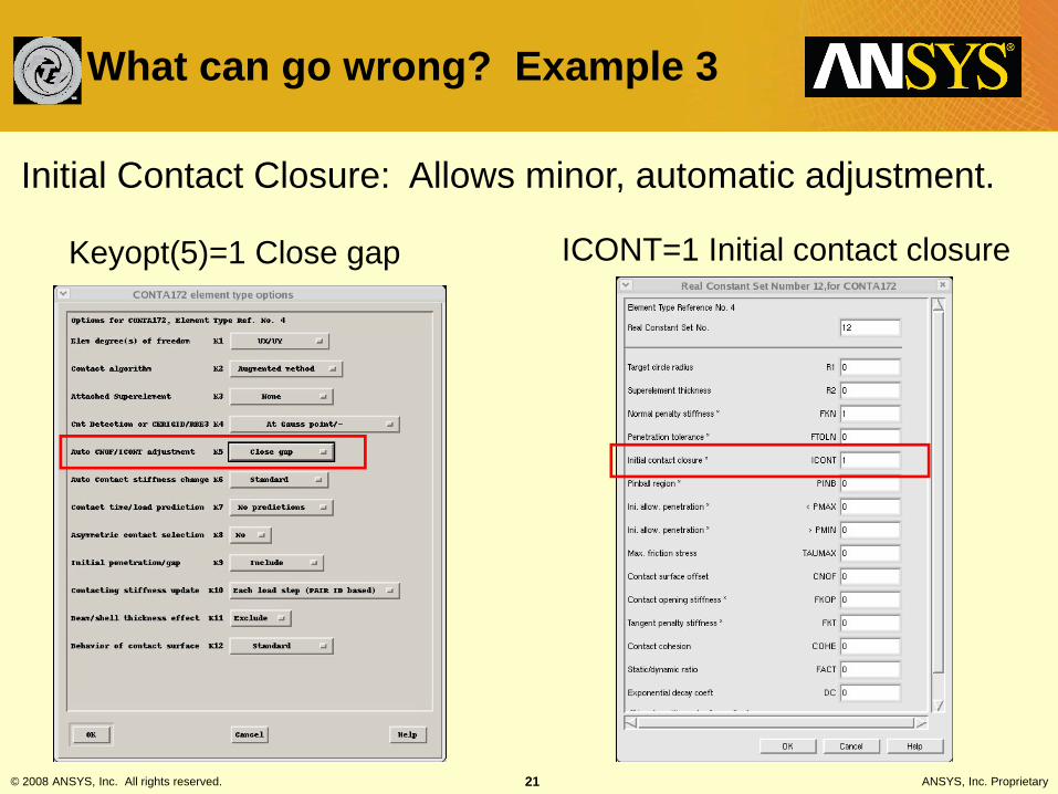
Keyopt(5)=1 Close gap ICONT=1 Initial contact closure
What can go wrong? Example 3
Initial Contact Closure: Allows minor, automatic adjustment.
© 2008 ANSYS, Inc. All rights reserved. 22 ANSYS, Inc. Proprietary
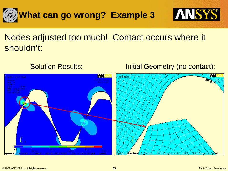
Solution Results: Initial Geometry (no contact):
Nodes adjusted too much! Contact occurs where it shouldn’t:
What can go wrong? Example 3

© 2008 ANSYS, Inc. All rights reserved. 23 ANSYS, Inc. Proprietary
Better solution: Move gear slightly to create initial contact.
What can go wrong? Example 3
© 2008 ANSYS, Inc. All rights reserved. 24 ANSYS, Inc. Proprietary
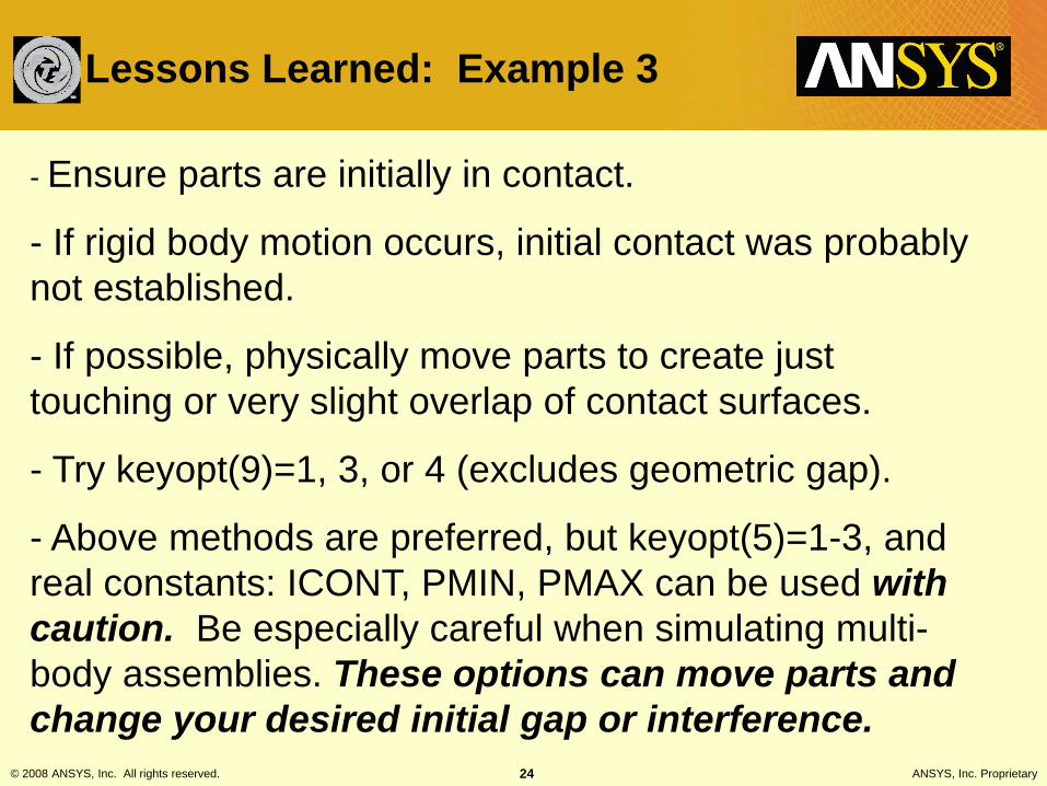
- Ensure parts are initially in contact.
- If rigid body motion occurs, initial contact was probably not established.
- If possible, physically move parts to create just touching or very slight overlap of contact surfaces.
- Try keyopt(9)=1, 3, or 4 (excludes geometric gap).
- Above methods are preferred, but keyopt(5)=1-3, and real constants: ICONT, PMIN, PMAX can be used with caution. Be especially careful when simulating multi-body assemblies. These options can move parts and change your desired initial gap or interference.
Lessons Learned: Example 3
© 2008 ANSYS, Inc. All rights reserved. 25 ANSYS, Inc. Proprietary
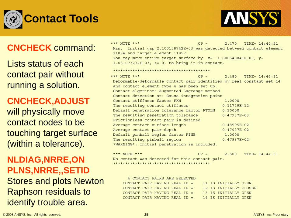
CNCHECK command:
Lists status of each contact pair without running a solution.
CNCHECK,ADJUSTwill physically move contact nodes to be touching target surface (within a tolerance).
NLDIAG,NRRE,ON PLNS,NRRE,,SETID Stores and plots Newton Raphson residuals to identify trouble area.
*** NOTE *** CP = 2.470 TIME= 14:44:51Min. Initial gap 2.100158742E-03 was detected between contact element11884 and target element 11857.You may move entire target surface by: x= -1.800540841E-03, y=1.081073272E-03, z= 0, to bring it in contact.
****************************************
*** NOTE *** CP = 2.480 TIME= 14:44:51Deformable-deformable contact pair identified by real constant set 14and contact element type 4 has been set up.Contact algorithm: Augmented Lagrange methodContact detection at: Gauss integration pointContact stiffness factor FKN 1.0000The resulting contact stiffness 0.11749E+12Default penetration tolerance factor FTOLN 0.10000The resulting penetration tolerance 0.47937E-03Frictionless contact pair is definedAverage contact surface length 0.48595E-02Average contact pair depth 0.47937E-02Default pinball region factor PINB 1.0000The resulting pinball region 0.47937E-02*WARNING*: Initial penetration is included.
*** NOTE *** CP = 2.500 TIME= 14:44:51No contact was detected for this contact pair.****************************************
4 CONTACT PAIRS ARE SELECTEDCONTACT PAIR HAVING REAL ID = 11 IS INITIALLY OPENCONTACT PAIR HAVING REAL ID = 12 IS INITIALLY CLOSEDCONTACT PAIR HAVING REAL ID = 13 IS INITIALLY OPENCONTACT PAIR HAVING REAL ID = 14 IS INITIALLY OPEN
Contact Tools

© 2008 ANSYS, Inc. All rights reserved. 26 ANSYS, Inc. Proprietary
Contact Trouble Shooting Guide
• All contact convergence problems fall in one of two categories (or both):
1. Failure to detect contact resulting in rigid body motion.
2. Contact achieved, but failure to reduce out-of-balance residual forces below convergence criteria.
• Use the output to determine which problem you have! The recommended corrective actions are different for each problem.

© 2008 ANSYS, Inc. All rights reserved. 27 ANSYS, Inc. Proprietary
Still have RBM? Yes
Failure to Detect Contact Resulting in Rigid Body Motion
Review contact pair summary. If there are initial gaps, move parts to establish initial contact, or use CNCHECK,ADJUST to align nodes.
Use contact damping – With standard contact, set FKOP to negative value (Try starting value of -10). Ramp loads over several substeps.
For initially open contacts that you expect to close, increase pinball (PINB).
Add a weak spring for stability – Set contact behavior to no separation (always) keyopt(12)=4, Set FKOP=small value.
Still have RBM? Yes
Still have RBM? Yes
Still have RBM? Yes
Run initial load step with small displacement constraint to seat contacts (very slight overlap). Then remove constraints and apply desired loads in second load step.

© 2008 ANSYS, Inc. All rights reserved. 28 ANSYS, Inc. Proprietary
Still not converged?
Failure to Reduce out-of-balance Residuals Below Convergence Criteria
Reduce FKN to 0.1 or 0.01. Ramp load in 5+ substeps. (Verify that penetration is acceptable)
If large interference fit, use keyopt(9)=4 (CNOF only, ramped). Set behavior to no separation (always) keyopt(12)=4 with small value for FKOP. Ramp loads in several substeps (5+).
Contact stiffness update: Try keyopt(10)=2 [pair based, each iteration], then keyopt(10)=3 [element based, each substep] May try options 4, or 5 for stubborn problems.
Auto-stiffness change: Set keyopt(6)=2 [Very Aggressive]. -- Good success with this option! Can even reduce iterations on well behaved problems. I often use this as my default.
Still not converged?
Still not converged?
So frustrated you could strangle a puppy? Other options: Add small amount of friction [mu=0.05], Reduce FKN another 10x, consider ramping FKN up over successive load steps if penetration too great. Sacrifice a virgin.
Identify contact pair(s) causing trouble. If not obvious, set NLDIAG,NRRE,ON. Run solution, Plot out-of-balance residuals using PNLS,NRRE.

© 2008 ANSYS, Inc. All rights reserved. 29 ANSYS, Inc. Proprietary
Contact Trouble Shooting Guide
• Options I Do Not recommend: – Symmetric contact – no benefit for convergence
issues. – CNOF/ICONT Automated adjustment keyopt(5)>1
This can cause contact where you don’t want it, or change desired gap or interference. Better to address alignment issues with other methods.