2005 valve catalog full asahi
TRANSCRIPT

1
The Advantagesof Thermoplastics
DISTRIBUTED BY:
22222
66666
1010101010
1414141414
1515151515
1616161616
1818181818
1919191919
2020202020
2121212121
2222222222
2323232323
2424242424
2525252525
2626262626
2828282828
3232323232
3434343434
3737373737
3939393939
4242424242
4444444444
4646464646
5050505050
5454545454
5757575757
6060606060
6262626262
6565656565
6666666666
6868686868
7272727272
7575757575
8080808080
8181818181
8282828282
8383838383
8888888888
9090909090
9292929292
9494949494
9898989898
100100100100100
105105105105105
107107107107107
111111111111111
113113113113113
Thermoplastics vs. MetalUnderstanding the benefits and limitations of bothadvanced thermoplastics and metals is essential tomaking an informed choice in valve materials.For services up to 250ºF and pressures up to 230psi, thermoplastic valves outperform metal withrespect to corrosion, abrasion and freeze resistance,and lower installed cost. Over 70% of all industrialvalve applications fall within these ranges. In highpressure, high temperature applications, metals areyour only choice. For all other process lines, fromwet chlorine, plating solutions, and acid wastes todemineralized water, thermoplastic valve and pipingmaterials are your best solution.Knowing the compatibility of the process materialwith the valve materials of construction, whichinclude body, seat, seals, gaskets, diaphragms, discs,plugs, balls, packings and trims – non-wetted as wellas wetted parts – impacts the valve's life andperformance and contributes to its overall cost. Inthis catalog we have made every attempt to provideyou with information which will allow you to make theright selection.
Thermoplastic Materials and Valve Types
Type 21 Ball Valves
Multiport® Type 23 Ball Valves
Omni® Ball Valves
Labcock® Valves
Quarter-Bloc® Ball Valves
Electromni® Actuated Ball Valves
Electrically Actuated Ball Valves
Ball Valve Stem Extensions and Options
Series 92 Electric Actuators
Series 94 Electric Actuators
Electrically Actuated Multiport Valves
Pneumatic Actuators
Pneumatically Actuated Ball Valves
Pneumatically Actuated Multiport Valves
Type 56 Butterfly Valves
Type 75 Butterfly Valves
Type 55 Butterfly Valves
Pool Pro® Butterfly Valves
Damper Style Butterfly Valves
PDCPD Giant Butterfly Valves
Butterfly Valve Stem Extensions and Options
Electric/Pneumatic Actuated Butterfly Valves
Type 14 Flanged Diaphragm Valves
Type 14 True Union Diaphragm Valves
Type 14 Pneumatically Actuated Valves
Type 15 Flanged Diaphragm Valves
Type "G" Diaphragm Valves
Diaphragm Valve Stem Extension and Options
Electric and Pneumatic Actuator Options
Swing Check Valves
Ball Check and Foot Valves
Gate Valves
Gate Valve Stem Extensions and Options
Electrically Actuated Gate Valves
Gaskets
Constant Flow Valves
Sediment Strainers
Sight Glass Gauge Valves
Type A Pressure Relief Valves
Type E Pressure Relief Valves
Globe Valves
Globe Control Valves
Compact Control Valves
AS-i Bus Systems
Technical Data
Part Numbers

ASAHI/AMERICARev. C 03-05
2
PVC (Polyvinyl Chloride)Cell Classification: 12454A, ASTM D 1784(Formerly, TYPE I, GRADE I)Properties: Over-all balanced properties –Excellent chemical resistance, strength, rigidity andmodulus of elasticity
Temperature Range: 32˚ – 140˚ F
CPVC (Chlorinated Polyvinyl Chloride)Cell Classification: 23567A, ASTM D 1784(Formerly, TYPE IV, GRADE I)Properties: Similar to PVC
Temperature Range: 32˚ – 195˚ F
PP (Polypropylene)Cell Classification: 0210B67272, ASTM D 4101-92bProperties: Excellent chemical resistance, highlycrystalline, lightest of plastics
Temperature Range: - 4˚ – 195˚ F
PVDF (Polyvinylidene Fluoride)Cell Classification: TYPE II, ASTM D 3222-91AProperties: Superior chemical and abrasionresistance, high mechanical strength, dielectricproperties
Temperature Range: - 40˚ – 250˚ F
ELASTOMERIC AND OTHER MATERIALS
PTFE (Polytetrafluoroethylene)Properties: Nearly insoluble and chemically inert,thermal stability, non-flammable, dielectric, naturallylubricant
Temperature Range: - 40˚ – 302˚ F
EPDM (Ethylene Propylene Diene Terpolymer)Properties: Good for acids, many aggressivechemicals, alcohol, ozone/weathering
Temperature Range: - 40˚ – 195˚ F
FKM (FKM = Fluorocarbon Rubbers)Properties: Most chemically resistant, balancedand excellent over-all properties
Temperature Range: - 20˚ – 302˚ F
NITRILE (NBR = Nitrile-Butadiene Rubbers)Properties: Excellent for oil, alcohol, abrasionresistant
Temperature Range: - 5˚ – 212˚ F
Materials Used in Asahi ValvesTHERMOPLASTICS
Thermoplastic Materials
Thermoplastics are the following:
• Dielectric
• Low thermal conductivity
• Smoother than metal for better flow rates andless energy required to move fluids
• Made to last longer than metal, even when incontact with corrosive liquids.
• Pure, so they do not contaminate the fluids theytransport.
• Chemically resistant
• Corrosion resistant, much more so than metals,which is why thermoplastics are favored by theEPA
• Lightweight, averaging a weight of 1/16th ofcomparable metal materials.
• Used in many industries including semi-conductor, mining, pulp and paper,electroplating, printing, landfills, aquaculture,waste water treatment, aquariums, themeparks and cruise ships.
• Lower in total material and installation coststhan conventional metal systems
• More efficient than metals, especially inoperational efficiencies including chemicalinertness, resistance to permeation andimpurity absorption, abrasion and freezeresistance.
• Advancing more steadily than their metalcounterparts. These advances in thermoplasticshave made possible the needed strength andheat/pressure tolerance for the vast majorityof fluid flow applications.
• Easier to install than metals, because oflightness in weight, good maneuverability, andcompact size.
The Benefits of ThermoplasticsThe advantages of using thermoplastics areconstantly being discovered. Over the past fewyears, there has been a dramatic increase in theapplication of thermoplastic valves and pipingsystems in areas where metal valves were thoughtto be the only solution. Even the most corrosionresistant metals are still susceptible to galvanic andelectrolytic corrosion, resulting in scale build-upwhich reduces flow rates and increases pressuredrop. Asahi/America is actively trying to educateend users to upgrade to thermoplastic systems.
Materials Used in Asahi Valves

35 Green Street, P.O. Box 653, Malden, MA 02148 • Tel: 800-343-3618 • 781-321-5409 • Fax: 800-426-7058 • E-mail: [email protected] at our interactive web site for on line ordering, product availability, order tracking, and many useful features: www.asahi-america.com
3
Asahi/America thermoplastic valves provide adependable and economical way to handle corrosivechemicals, including sulfuric and hydrofluoric acid,nitric acid, oxidizing chemicals, caustics, solvents,halogens, and various other hostile fluids. Theyperform at temperatures up to 250ºF, pressures upto 230 psi, and flows up to 18,500 gpm. All valvesmeet or exceed ANSI Class 6 shut-off.What follows are brief descriptions of the valvetypes offered by Asahi/America. For further details,see the individual valve sections contained herein.
BALL VALVES
This valve performs an on/off or modulatingfunction. Its name is derived from the flow-controlling ball located within the body of the valve. Ahole through the center of the ball along one axisconnects the inlet and outlet ports of the body. Theball itself is held in place by, and rotates 90º within,PTFE seats. These provide permanent lubricationand keep the valve "bubble-tight." They are backed byelastomeric cushions, which provide pressureagainst the ball and at the same time compensatefor wear. Elastomer O-rings are used for stem andcarrier seals to prevent leakage to the atmosphere.In the open position, the flow is straight-through, andthere is minimal pressure drop when the portingthrough the ball is the same size as the insidediameter of the pipe.
Asahi/America ball valves are quick opening andclosing; a quarter turn is all that is necessary. Theyare easy to maintain, and they provide tight sealingwith low torque. Asahi/America offers three majortypes of ball valves: (1) Type 21True Union ball valves;(2) Omni® ball valves; (3) Type 23 True UnionMultiport ball valves. True Union ball valves can belifted from the line, without having to move the piping,simply by loosening the two union nuts. The valves canbe disassembled, and parts may be replaced. TheOmni series are economical, one-piece valves whichcannot be taken apart. Multiport ball valves are three-way ball valves with True Union design. The use of aMultiport ball valve simplifies piping and eliminates theneed for an additional valve and Tee fitting. An “L”ported ball valve permits flow from the bottom entryto either the left or right ports or to an OFF position.An optional Tee ported ball allows simultaneous leftand right flow. The Asahi/America True Union ballvalves and Multiport ball valves may be electrically orpneumatically operated.
Thermoplastics
6
1. Actual temperature that any particularvalves can be used is often different fromthe above, since individual valve structure isdifferent and a variety of materials is usedin the same product. Refer to tables of“Working Pressure vs. Temperature”.
2. For details of chemical compatibility, consultfactory for recommendation.
3. Asahi/America valves are not recommendedfor use in compressed gas services.
4. Only hydrostatic pressure is recommendedwhen testing, with a gradual increase inpressure.
5. Recommended fluid velocity is 5 ft/sec tominimize water hammer and prematurewearing.
Caution:
* Trade mark of E. I. du Pont de Nemours and Company** Trade mark of Asahi Glass Co., Ltd.
HYPALON®* (CSM = ChlorosulphonylPolyethylene)Properties: Excellent for oxidizing acids, alkalis,abrasion resistant
Temperature Range: - 5˚ – 175˚ F
NEOPRENE® * (CR = Chloroprene Rubbers)Properties: Good for acids, alkalis, lower gaspermeability, impact resilient
Temperature Range: - 5˚ – 175˚ F
AFLAS ® ** (TFE Elastomer =Tetrafluoroethylene/propylene dipolymer)Properties: Wide varieties of Chemicals, Bleaches,Pulp and Paper Liquids
Temperature Range: Up to 450˚ F
BUTYL (IIR = Isobutene-isoprene rubbers)Properties: Acids and alkalis, weathering less gas-permeability, good flexing strength
Temperature Range: - 22˚ – 195˚ F
UHMWPE (Ultra High Molecular WeightPolyethylene)Properties: Abrasion and chemically resistant
Materials Used in Asahi Valves
Valve TypesProduct Discussion and Overview
ELASTOMERIC AND OTHER MATERIALS (CONT.)

ASAHI/AMERICARev. C 03-05
4
CHECK VALVES
Valve TypesBUTTERFLY VALVES
The flow through a globe valve follows a coursethat takes nearly two 90º changes in direction.But, because the seating of a globe valve isparallel to the line of flow of the liquid, it can beused to throttle the flow to any requireddegree or to give positive shut-offs. Theeconomy and dependability of the Asahi/America globe valve make it desirable for manyapplications where this pressure drop is notcritical. These valves are designed for manualoperation only.
The diaphragm valve offers many combinations ofbody materials and elastomeric diaphragmmaterials. The valve design is abrasion-resistantand non-clogging. When the diaphragm, which isconnected to the stem of the valve by a com-pressor, is pulled away from the bottom of the valvebody or weir, the path of the fluid has a smooth,streamlined flow. Slurries at low pressure thatwould normally clog most other valve designs easilypass through a diaphragm valve. The bonnet andworking parts are completely isolated from the linefluid and only the body and diaphragm materialsmust be considered for service compatibility. Thevalve is a top-entry design, allowing in-linemaintenance. The valve is suitable for throttling andON/OFF service in applications ranging from watertreatment to chemical abrasion processes. Dia-phragm valves are operated manually, electrically,or pneumatically.
DIAPHRAGM VALVES
This is another quarter-turn valve related to thefamily of ball valves. It has many process controlmonitoring and fluid sampling uses in thelaboratory. These are quarter-turn valves, whichcome in a variety of configurations: male thread xmale thread, male thread x hose, hose x hose,female thread x female thread, and female thread xmale thread. They may be used for simple ON/OFFservice or for calibrating flow.
LABCOCK® VALVES
The gate valve is the most widely used ON/OFFvalve for large diameter, full port applications.When the valve is fully open, it allows straight-through passage through an opening that isessentially the same size as the inside diameterof the connecting pipe. This is why there is littlepressure drop through an Asahi/America gatevalve. The valve operates when the handwheeland stem screw (or electric actuator) move acylindrical plug, the gate, up and down at rightangles to the fluid flow. Traditionally, gate valveshave been used only for ON/OFF service, butbecause the unique Asahi/America sliding plugdesign provides a larger seating area thanconventional gate valves, it can be used forthrottling. This significantly larger seating area,which runs 360 degrees around the cylindricalplug, has also virtually eliminated the valvechatter normally associated with Gate valves.Asahi/America features two types of gatevalves, one with a solid polypropylene plug andthe other with a resilient elastomeric plug. Eachvalve is specifically designed to handle uniquecorrosive applications. Both style valves areavailable in “non-rising stem” or in “rising stem”designs.
GATE VALVES
The name of this valve comes from the wing-likeaction of the flow-controlling disc, which operates atright angles to the flow. The disc has about the samediameter as the connecting pipe, and the flow isstraight-through, with a low pressure drop. Main-tenance is easy due to the small number of movingparts. The Butterfly valve can be used either as an“ON/OFF” or modulating type of valve. Asahi/America has recently developed the advanced Type56 valve, which has no metal to media or environ-ment contact whatsoever. These valves may beoperated manually, electrically, or pneumatically.
GLOBE VALVES
Check valves are self-contained, automatic valves,which are used to prevent the reversal of flow in aline. When open and under flow pressure, thechecking mechanism will move freely in the media,offering very little resistance and minimal pressuredrop. Asahi/America provides two basic types ofcheck valves: swing check valves and ball checkvalves. A swing check valve utilizes a swinging disc,which requires only minimal back pressure to closethe valve. This valve can also be modified, with alever and weight or spring, to assist in seatingfaster to eliminate shock. The Asahi/America ballcheck valve employs a free moving ball, whichunseats to permit flow in one direction, but sealsagainst a seat to prevent backflow. Both types ofvalves may be installed vertically or horizontally.

35 Green Street, P.O. Box 653, Malden, MA 02148 • Tel: 800-343-3618 • 781-321-5409 • Fax: 800-426-7058 • E-mail: [email protected] at our interactive web site for on line ordering, product availability, order tracking, and many useful features: www.asahi-america.com
5
Valve Types
AUTOMATED VALVES
Asahi valve gaskets offer a unique double convex ringdesign that gives optimum sealing with only 1/3 thetorque commonly required with flat faced gaskets.Asahi/America offers EPDM gaskets from 1/2" to12"; PTFE-bonded EPDM gaskets in sizes from 1/2"to 12"; and PVDF-bonded EPDM gaskets from 1/2"to 10".
The thermoplastic pressure relief valve protectsequipment and systems against overpressures orsudden pressure surges. Able to handle highlycorrosive or ultrapure liquids, it prevents pumpsfrom dead-heading due to unexpected shut-offsdownstream (also known as a “bypass relief valve”.)It maintains back pressure in closed-loop systemsto make pumps run more smoothly (also known asa back pressure valve.)
PRESSURE RELIEF VALVES
The Asahi/America globe control valve is the mostadvanced available in design, features, perform-ance, and cost effectiveness. Its design includessuperior proportional control characteristics andsafety features for a wide variety of applications,ranging from common fluids to the mostaggressive chemicals. Accurate fluid control isachieved by positioning the valve plug to vary theaperture between the plug and the seat ring. Thevalve design allows the use of different plug/seatsets to provide desired flow versus travelcharacteristics. A wide range of controllable Cv isavailable, from 0.23 to a maximum of 105. Reducedtrim is an option. For greater flow requirements,Asahi/America offers an extensive line ofmodulating ball and butterfly control valves. Bothelectric and pneumatic actuators are available forany control mode.
PTFE bellows stem sealing eliminates old-fashionedpacking glands, minimizing valve maintenance, andincreasing performance, safety, reliability, anduseful life. The Asahi/America Globe Control valvesprovide long, reliable, accurate, and economic lifewithout resorting to highly expensive control valvesin exotic materials. Cost is surprisingly low for initialpurchase, installation, operation, and maintenance.
GLOBE CONTROL VALVES
Ball valves, butterfly valves, diaphragm valves, andgate valves are often automated with pneumatic orelectric actuators. This allows remote operation fora variety of reasons: savings in labor, plant safety,product quality assurance, and automaticsequencing, to name a few. The choice of actuatortype depends on many factors, including availabilityof air supply, cycling requirements, condition of theenvironment, compatibility with the type of controloperation, and cost. Positioners may be mounted onthese valves if flow control is required.
GASKETS
Sediment strainers protect pipeline componentssuch as pumps and meters by removing suspendedsolids and impurities. Transparent thermoplasticconstruction permits easy detection of the screen’scondition.
SEDIMENT STRAINERS
The sight glass/gauge valve is the most convenientway to visually monitor the liquid level in tanks. Itsthermoplastic construction produces excellentcorrosion resistance, and its compact designpermits it to be safely located close to the tank.
SIGHT GLASS GAUGE
CONSTANT FLOW VALVES
Using the constant flow valve provides an accurateway of controlling flow without automation (neitherelectricity nor an air supply is required). Accuratecontrol is achieved by the globe style body and seat-and-plug configuration. This unique design allowsthe valve to maintain a constant preset flow, even ifthe differential pressure changes. The allthermoplastic construction makes it ideal forsemiconductor, chemical, swimming pool, and saltwater applications.

ASAHI/AMERICARev. C 03-05
6
• Pressure rated up to 230 psi (PVC, CPVC, PVDF)
• Double O-ring seals on stem for an addedprotection.
• Full bore, sizes 1/2" – 2"
• Full vacuum rated, all sizes
• Blocks in two directions, upstream anddownstream, leaving full pressure on theopposite end of the valve
• Integrally molded ISO mounting pad for bothmanual and actuated operations
• Integrally molded base pad to mount valvesSecurely or panel mounting
• PTFE seats with elastomeric backing cushionsensure bubble-tight shut-off and a low fixedtorque, while at the same time compensatingfor wear
• True Union design for easier installation orrepairs without expanding the pipe system
• Built-in spanner wrench on the handle for valvedisassembly and assembly
• Two sets of end connectors (socket andthreaded) included with all PVC and CPVC valvesin sizes 1/2"– 2"
• CPVC threaded end connectors on sizes1/2" – 1" come with stainless steel reinforcingrings
SpecificationsSizes: 1/2" – 6"
Models: PVC & CPVC: Socket, Threadedand Flanged (ANSI)PP & PVDF: IPS and Metric (DIN)Socket, Threaded, Butt andFlanged (ANSI)
Bodies: PVC, CPVC, PP and PVDFSeats: PTFE backed with EPDM or FKMSeals: EPDM or FKM or AFLAS®‡
Sizes 1/2" - 4" PVC/EPDM/FKM Models available with NSF-61 Certification ‡ Trademark of Asahi Glass Co., Ltd.
Options• Pneumatic and electric actuators & accessories• Stem extensions• 2" square operating nut or “T” nut• Locking and/or spring return handles• Limit switches• Vented Ball
Parts List (Sizes 1/2" – 2")
* Used for flanged end**Used for CPVC body, threaded end, 1/2”–1”
Standard Features (Sizes 1/2" – 6")
Type 21 Ball Valve
STRAP
.ON NOITPIRCSED .SCP LAIRETAM1 ydoB 1 FDVP,PP,CVPC,CVP
2 llaB 1 FDVP,PP,CVPC,CVP
3 reirraC 1 FDVP,PP,CVPC,CVP
4 rotcennoCdnE 2 FDVP,PP,CVPC,CVP
5 tuNnoinU 2 FDVP,PP,CVPC,CVP
6 metS 1 FDVP,PP,CVPC,CVP
7 taeS 2 EFTP8 )A(gniR-O 2 srehtO,MKF,MDPE9 )B(gniR-O 1 srehtO,MKF,MDPE
01 )C(gniR-O 2 srehtO,MKF,MDPE
11 )D(gniR-O 1 srehtO,MKF,MDPE
21 )E(gniR-O 1 srehtO,MKF,MDPE
31 *gniRpotS 2 FDVP
41 eldnaH 1 SBA
a4 **gniR 2 leetSsselniatS403

35 Green Street, P.O. Box 653, Malden, MA 02148 • Tel: 800-343-3618 • 781-321-5409 • Fax: 800-426-7058 • E-mail: [email protected] at our interactive web site for on line ordering, product availability, order tracking, and many useful features: www.asahi-america.com
7
21
L
13810 3 59
14
4
ød øD
P.C
.D.
C
H1
A
12
n- øh
6
11
7
H øD1
FLANGED END
322-øS Depth S
S1
t
1 1øD
t
L
ød
SPIGOT END
l
1
L
ød øD1
4
THREADED END
4a
l
L
4
SOCKET END
ød2
øDød1 1
l
Dimensions (Sizes 1/2" – 2")
LANIMONEZIS
d
DEGNALF TEKCOS
051SSALCISNA
L t
CVPC,CVP )NID(FDVP,PP )SPI(FDVP,PP
08HCSMTSA
L
26961NID
L d1 l LSEHCNI mm D C n h d1 d2 l d1 d2 l2/1 51 95.0 05.3 83.2 4 26.0 36.5 74.0 848.0 638.0 578.0 54.4 867.0 067.0 75.0 09.3 38.0 78.0 54.4
4/3 02 97.0 88.3 57.2 4 26.0 77.6 55.0 850.1 640.1 000.1 80.5 569.0 759.0 36.0 94.4 30.1 00.1 80.5
1 52 89.0 52.4 21.3 4 26.0 63.7 55.0 523.1 013.1 521.1 57.5 042.1 232.1 17.0 48.4 03.1 31.1 57.5
1 4/1 23 62.1 26.4 05.3 4 26.0 84.7 36.0 076.1 556.1 052.1 64.6 355.1 345.1 18.0 74.5 56.1 52.1 64.6
1 2/1 04 75.1 00.5 88.3 4 26.0 53.8 36.0 219.1 498.1 573.1 42.7 749.1 739.1 39.0 38.5 98.1 73.1 42.7
2 05 10.2 00.6 57.4 4 57.0 12.9 36.0 783.2 963.2 005.1 32.8 164.2 544.2 80.1 39.6 63.2 05.1 32.8
LANIMONEZIS
DEDAERHT
1D H H1 A
)DNETTUB(TOGIPS
S1 S2 S3d1 l L
FDVP,PP
2443NID PP FDVP
LSEHCNI mm d1 l t t2/1 51 2/1 TPN41- ........ 95.0 20.4 98.1 30.2 41.1 26.3 787.0 827.0 890.0 570.0 288.4 57.0 92.0 34.0
4/3 02 4/3 TPN41- ........ 76.0 27.4 63.2 43.2 83.1 49.3 489.0 668.0 601.0 570.0 076.5 57.0 92.0 34.0
1 52 11-1 2/1 TPN ........ 97.0 61.5 67.2 86.2 45.1 33.4 062.1 688.0 811.0 490.0 360.6 57.0 92.0 34.0
1 4/1 23 1 4/1 11- 2/1 TPN ........ 78.0 19.5 32.3 71.3 58.1 67.4 575.1 420.1 641.0 490.0 058.6 81.1 53.0 95.0
1 2/1 04 1 2/1 11- 2/1 TPN ........ 89.0 24.6 49.3 05.3 71.2 61.5 969.1 062.1 181.0 811.0 836.7 81.1 53.0 95.0
2 05 11-2 2/1 TPN ........ 01.1 67.7 69.4 40.4 06.2 62.6 084.2 714.1 822.0 811.0 918.8 81.1 53.0 95.0
Ball ValvesType 21

ASAHI/AMERICARev. C 03-05
8
14
15
e
10
L
2 1 7 9 53 8 13 4n-øht
e 1
ød
3
1H
P.C
.D.ø
d C
øD
2
11
H
12
6
A
1S
L
4
L
4
SOCKET END
ød
2
øD
ød
1 1
THREADED END
1ø
d
øD
1
4
L
ød øD
1 1
SPIGOT END
t
l
l
l
FLANGED END
Dimensions (Sizes 2 1/2" – 4") FOR 6" SIZE CONSULT FACTORY
LANIMONEZIS
DEDAERHT
d3 1D H H1 A
)DNETTUB(TOGIPS
e1 e2 S1d1 l L
FDVP,PP
2443NID PP FDVP
LSEHCNI mm d1 l t t2 2/1 56 2 2/1 TPN8- 62.1 64.8 82.2 42.5 69.4 38.2 78.7 359.2 694.1 272.0 241.0 27.9 53.0 42.0 98.1
3 08 TPN8-3 ....... 83.1 93.01 07.2 89.5 15.5 53.3 54.9 345.3 694.1 323.0 961.0 16.11 34.0 82.0 71.2
4 001 TPN8-4 ....... 77.1 71.41 45.3 72.8 10.7 33.4 18.11 133.4 257.1 493.0 902.0 27.21 34.0 13.0 65.2
Type 21 Ball Valves
LANIMONEZIS
d
DEGNALF TEKCOS
051SSALCISNA
L t
CVPC,CVP )NID(FDVP,PP )SPI(FDVP,PP
08HCSMTSA
L
26961NID
L d1 l LSEHCNI mm D C n h d1 d2 l d1 d2 l2 2/1 56 65.2 7 5.5 4 57.0 2.01 17.0 988.2 868.2 57.1 54.9 329.2 119.2 22.1 51.8 88.2 257.1 54.9
3 08 70.3 5.7 6 4 57.0 79.11 17.0 615.3 294.3 578.1 1.11 215.3 894.3 4.1 88.9 84.3 478.1 1.11
4 001 49.3 9 5.7 8 57.0 56.41 17.0 815.4 194.4 2 9.31 392.4 872.4 36.1 2.21 84.4 252.2 73.41
NOTE: Quantity on Nos. 3 and 9 (see p. 6) is 2.
)"2–"2/1MORFSREBMUNTNEREFFID(STRAP
.ON NOITPIRCSED .SCP LAIRETAM01 noihsuC 2 srehtO,MKF,MDPE
51 wercS 1 leetSsselniatS403

35 Green Street, P.O. Box 653, Malden, MA 02148 • Tel: 800-343-3618 • 781-321-5409 • Fax: 800-426-7058 • E-mail: [email protected] at our interactive web site for on line ordering, product availability, order tracking, and many useful features: www.asahi-america.com
9
Sample Specification
Pressure vs. Temperature (PSI, WATER, NON-SHOCK)
• Do not use ball valves where media hassuspended particles. Use the following valves:Butterfly Valves – PVDF disc is most abrasionresistant and make sure of chemical compatibility.Diaphragm Valves – Elastomeric diaphragm isdesigned for handling suspended particles.
• Volatile fluids such as sodium hypochlorite (NaClO)and hydrogen peroxide (H
2O
2) could be trapped
and gasified within the valve. We can provide youwith a Type 21 ball valve with a vented ball torelieve pressure build-up inside the valve.
Caution
What if the fluid still flows when valve is closed?1. Carrier is not properly tightened. Tighten it.2. PTFE seat is damaged or worn. Replace
seat.3. Foreign material is caught between ball and
PTFE seat. Remove material and clean.4. Ball is damaged or worn. Change ball.
What if fluid leaks outside of valve?1. Union nut not properly tightened. Retighten.2. Carrier is not properly tightened. Thread it in
firmly.3. Carrier or face O-ring is damaged, worn, or
missing. Replace O-ring.What if handle does not rotate smoothly?
1. Foreign material has formed on the ball orseat. Clean both.
2. Internal part(s) chemically attacked orswollen. Refer to Asahi/America ChemicalResistance Chart for compatibility. Replacepart(s) as required.
3. Carrier over-tightened. Retighten properly.What if handle rotates too freely?
1. Stem is damaged. Replace stem.2. Handle is not engaged with stem.
Disassemble and reengage. Inspect.3. Engaging part of stem and/or ball is
damaged. Change stem and/or ball.
Troubleshooting
Weight (POUNDS)Cv Values
• Never remove valve from pipeline under pressure.• Always wear protective gloves and goggles.• Watch out for trapped fluid in valve. It is safe to
close valve before removing it from the pipeline.
Caution
LANIMONEZIS
CVP CVPC PP FDVP
F0̊3F0̊7
F1̊7F5̊01
F6̊01F0̊21
F1̊21F0̊41
F0̊3F0̊7
F1̊7F5̊01
F6̊01F0̊21
F1̊21F0̊41
F1̊41F5̊71
F6̊71F5̊91
F5̊-F5̊8
F6̊8F0̊21
F1̊21F0̊41
F1̊41F5̊71
F5̊-F0̊7
F1̊7F5̊01
F6̊01F0̊41
F1̊41F5̊71
F6̊71F0̊12SEHCNI mm
2/1 2- 05-51 032 071 051 03 032 071 051 021 57 55 051 011 09 55 032 581 051 511 582 2/1 56 032 071 051 AN 032 071 051 021 57 55 051 59 07 04 032 581 051 511 58
3 08 032 071 051 AN 032 071 051 58 55 04 051 59 07 04 032 581 051 001 076-4 051-001 051 051 051 AN 051 051 051 58 55 04 051 59 07 04 051 051 051 001 07
Type 21 Ball Valves
All TYPE 21 Ball Valves, sizes 1/2” to 4”, shall be oftrue union design with two-way blocking capability.All O-rings shall be EPDM or FKM with PTFE seats.PTFE seats shall have elastomeric backing cushionof the same material as the valve seals. Stem shallhave double O-rings and be of blowout-proof design.The valve handle shall double as carrier removaland/or tightening tool. ISO mounting pad shall beintegrally molded to valve body for actuation. PVCconforming to ASTM D1784 Cell Classification12454-A, CPVC conforming to ASTM D1784 CellClassification 23567-A, PP Conforming to ASTMD4101 Cell Classification PP0210B67272 andPVDF conforming to ASTM D3222 Cell ClassificationType II. The ball valves, except PP, shall have apressure rating of 230 psi for sizes”1/2” to 3” and150 psi for 4” (150 psi for PP, all sizes) at 70 º F.Type 21 Ball Valves must carry a two-yearguarantee, as manufactured by Asahi/America, Inc.
LANIMONEZIS TEKCOS
DEDAERHTDEGNALF
SEHCNI mm
2/1 51 44.0 01.1
4/3 02 66.0 45.1
1 52 01.1 07.2
1 4/1 23 45.1 03.3
1 2/1 04 46.2 04.4
2 05 04.4 51.8
2 2/1 56 71.6 08.8
3 08 07.9 00.31
4 001 00.42 76.62
LANIMONEZIS CV
SEHCNI mm
2/1 51 41
4/3 02 92
1 52 74
1 4/1 23 27
1 2/1 04 551
2 05 091
2 2/1 56 563
3 08 014
4 001 086

ASAHI/AMERICARev. C 03-05
10
• True Union design on all three ports• Double O-ring seals on stem for added
protection• Integrally molded ISO mounting pad for both
manual and actuated operations• Blow-out proof, solid mold bottom entry design• Blocks from left or right union ports, leaving full
pressure on the opposite end of valve• Standard “L” port ball permits flow from
common port to either left or right port or to“OFF” position
• PTFE seats with elastomeric backing cushionsensure bouble-tight shut-off and a low fixedtorque, while at the same time compensatingfor wear
• Built-in spanner wrench on the handle for valvedisassembly and assembly
• All sizes rated for full vacuum service
• Eliminates need for additional valve and “Tee”
SpecificationsSizes: 1/2” – 6”
Models: PVC & CPVC: Socket, Threadedand Flanged (ANSI)
Bodies: PVC, CPVC, PP, PVDFSeats: PTFE backed with EPDM or FKMSeals: EPDM or FKM or AFLAS®†
Sizes 1/2" - 4" PVC/EPDM/FKM Models available with NSF-61 Certification
† Trademark of Asahi Glass Co., Ltd.
Options• Pneumatic and electric actuators & accessories• Stem extensions• 2" square operating nut or “T” nut• Locking handles• Limit switches• “T” port, Double "L" port
Parts List (Sizes 1/2" – 6")Standard Features (Sizes 1/2" – 6")
Cross Port Ball Options• 4 different flow patterns through 3 separate
ports are possible because of the crossed flowpatterns within the ball
• Changing position of handle changes flowpattern. Handle rotates 360º.
* Used for size 1/2" – 2", **Used for size 3" and 4"*** Used for flanged end****Used for CPVC body, threaded end, 1/2” – 1”
Multiport® Ball Valve Type 23
STRAP
.ON NOITPIRCSED .SCP LAIRETAM1 ydoB 1 FDVP,PP,CVPC,CVP
2 llaB 1 FDVP,PP,CVPC,CVP
3 reirraC 2 FDVP,PP,CVPC,CVP
4 rotcennoCdnE 3 FDVP,PP,CVPC,CVP
5 tuNnoinU 3 FDVP,PP,CVPC,CVP
6 metS 1 FDVP,PP,CVPC,CVP
7 taeS 2 EFTP
8 )A(gniR-O 3 srehtO,MKF,MDPE9 )B(gniR-O 2 srehtO,MKF,MDPE
01*noihsuC
2 srehtO,MKF,MDPE**)C(gniR-O
11 )D(gniR-O 1 srehtO,MKF,MDPE
21 )E(gniR-O 1 srehtO,MKF,MDPE
31 ***gniRpotS 3 FDVP
41 eldnaH 1 SBA
51 wercS 1 leetSsselniatS403
a4 ****gniR 3 leetSsselniatS403

35 Green Street, P.O. Box 653, Malden, MA 02148 • Tel: 800-343-3618 • 781-321-5409 • Fax: 800-426-7058 • E-mail: [email protected] at our interactive web site for on line ordering, product availability, order tracking, and many useful features: www.asahi-america.com
11
Dimensions (Sizes 1/2" – 4") For 6” size consult factory.
Multiport® Ball ValvesType 23
LANIMONEZIS
d 'd
DEGNALF DEDAERHT
D1 H A
051SSALCISNA
L t H1d2
l L H1SEHCNI mm D C n h2/1 51 95.0 95.0 05.3 83.2 4 26.0 36.5 74.0 07.3 2/1 TPN41- 95.0 20.4 98.2 98.1 30.2 26.3
4/3 02 97.0 97.0 88.3 57.2 4 26.0 77.6 55.0 05.4 4/3 TPN41- 76.0 27.4 84.3 63.2 43.2 49.3
1 52 89.0 89.0 52.4 21.3 4 26.0 63.7 55.0 42.5 11-1 2/1 TPN . 97.0 61.5 31.4 67.2 86.2 33.4
1 2/1 04 75.1 62.1 00.5 88.3 4 26.0 53.8 36.0 05.6 1 2/1 11- 2/1 TPN . 89.0 24.6 35.5 49.3 05.3 61.5
2 05 10.2 96.1 00.6 57.4 4 57.0 12.9 36.0 43.7 11-2 2/1 TPN . 01.1 67.7 16.6 69.4 40.4 62.6
3 08 70.3 07.2 05.7 00.6 4 57.0 79.11 17.0 60.01 TPN8-3 83.1 93.01 52.9 89.5 15.5 54.9
4 001 49.3 45.3 00.9 05.7 8 57.0 56.41 17.0 10.21 TPN8-4 77.1 71.41 77.11 72.8 10.7 10.21
DOUBLE "L" PORT DETAIL
FLANGED END ("L" PORT: STANDARD)
10 7 9 1
2
H1
H
L
tn- øh
ø d'
A
43 138
ø d
ø D
P.C
.D.
C
11 5
6
12
14
3"&4"
15 10
CROSS PORT DETAIL
øDød
L4a4
THREADED END
L
1 1
4
SOCKET END
2ød
ød1
øD1
ød
L
t
øD11
SPIGOT END
4

ASAHI/AMERICARev. C 03-05
12
Pressure vs. Temperature (PSI, WATER, NON-SHOCK)LANIMON
EZIS
CVP CVPC PP FDVP
F˚03F˚07
F˚17F˚501
F˚601F˚021
F˚03F˚021
F˚121F˚041
F˚141F˚571
F˚671F˚591
F˚5-F˚58
F˚68F˚041
F˚141F˚571
F˚5-F˚041
F˚141F˚571
F˚671F˚591
F˚691F˚012SEHCNI mm
2/1 -2 05-51 051 051 051 051 021 58 55 051 09 06 051 021 011 584-3 001-08 051 051 051 051 58 55 54 051 57 54 051 001 58 07
Multiport Ball® Valves Type 23
L-Port Double L-Port
Cross Port
Available Flow Patterns
T-Port
For Pneumatic Actuation:"Double L-Port" ball is supplied as a standard feature. Other configurations available as options.Pneumatic actuators are 2 position.For Electrical Actuation:"L-Port" ball is supplied as a standard feature. All other ball configurations are available as options.Electrical actuators are 2 position with the option for a third "Center" position.
Automation

35 Green Street, P.O. Box 653, Malden, MA 02148 • Tel: 800-343-3618 • 781-321-5409 • Fax: 800-426-7058 • E-mail: [email protected] at our interactive web site for on line ordering, product availability, order tracking, and many useful features: www.asahi-america.com
13
Type 23TroubleshootingWhat if the fluid still flows when valve is closed?
1. Carrier is not properly tightened. Tighten itfirmly.
2. PTFE seat is damaged or worn. Replaceseat.
3. Foreign material is caught between ball andPTFE seat. Remove material and clean.
4. Ball is damaged or worn. Change ball.What if fluid leaks between body and nuts?
1. Carrier or face O-ring is damaged, worn, ormissing. Replace O-ring.
What if stem leaks ?1. Stem is damaged. Replace stem.2. O-ring is damaged. Replace O-ring.
What if handle does not rotate smoothly?1. Foreign material has formed on the ball or
seat. Clean both.2. Internal part(s) chemically attacked or
swollen. Refer to Asahi/America ChemicalResistance Chart for compatibility. Replacepart(s) as required.
3. Carrier over-tightened. Tighten properly.What if handle rotates too freely?
1. Stem is damaged. Replace stem.2. Handle is not engaged with stem.
Disassemble and reengage. Inspect.
Multiport® Ball Valves
Cv Values Weight (POUNDS)
Sample SpecificationAll Type 23 Multiport ball valves shall be of moldedthermoplastic construction with union end on allthree ports. Carriers must thread into the body inorder to provide blocking capabilities in OFFposition. Stem shall have double O-Rings and be ofblow out proof design. The valve handle shall doubleas carrier removal and/or tightening tool. ISOmounting pad shall be integrally molded to valvebody. PVC conforming to ASTM D1784 CellClassification 12454-A, CPVC conforming toASTM D1784 Cell Classification 23567-A, PPconforming to ASTM D4101 Cell ClassificationPP0210B67272 and PVDF conforming toASTM D3222 Cell Classification Type II. Thevalves shall be rated to 150 psi at 70º F. PTFEseats must have elastomeric backing cushionof the same material as the valve seals, asmanufactured by Asahi/America, Inc.
• Never remove valve from pipeline under pressure.• Always wear protective gloves and goggles.• Watch out for trapped fluid in valve.• Only L-port and T-port valves are closed when
Handle is positioned perpendicular (90 degrees).• Even if Handle is perpendicular, valve is not
closed if the ball is in the following positions,based upon the following porting configurations:(a.) Double L-Port – Flow is to right or left(b.) Cross-Port – Flow is horizontal as in regularball valve.
Caution
LANIMONEZIS
CV
TROP-L L-LBDSEHCNI mm
2/1 51 4.7 3.6
4/3 02 01 5.8
1 52 32 02
1 2/1 04 34 63
2 05 95 54
3 08 031 99
4 001 062 002
LANIMONEZIS TEKCOS
DEDAERHTDEGNALF
SEHCNI mm
2/1 51 66.0 67.1
4/3 02 01.1 24.2
1 52 67.1 25.3
1 2/1 04 81.4 63.6
2 05 37.5 95.8
3 08 34.51 59.81
4 001 72.53 09.93

ASAHI/AMERICARev. C 03-05
14
A
L
ød øD1
ød
7 6 2 31L
ød
H
ød 1
øD
4
8
5
2ø
d
SOCKET END
THREADED END
1a
øD
1
øD
1
l
l
SpecificationsSizes: 3/8" – 3"
Models: Socket and ThreadedBodies: PVC, CPVC
Seats: PTFE backed with EPDMSeals: EPDM
Sizes 3/8" - 3" PVC/EPDM Models available with NSF-61 Certification
Omni® is a Trademark of Asahi/America, Inc.Omni® Ball Valve
Omni® Ball Valve
Weight (LBS.) Cv Values
• Blocks in two directions• Rugged structure• Unibody construction• Compact, low profile, short face-to-face dimensions• PTFE seat backed by EPDM for low stem torque• Rated for full vacuum service
Standard Features (Sizes 3/8" – 3")
• FKM backing cushions and O-ring• Electrically actuated
Sample Specification
Pressure vs. Temperature (PSI, WATER, NON-SHOCK)
Options
STRAP
.ON NOITPIRCSED .SCP LAIRETAM1 ydoB 1 CVPC,CVP
2 llaB 1 CVPC,CVP
3 rotcennoCdnE 1 CVPC,CVP
4 metS 1 CVPC,CVP
5 eldnaH 1 SBA
6 taeS 2 EFTP
7 noihsuC 2 srehtO,MDPE
8 gniR-O 1 srehtO,MDPEa1 *gniR 2 leetSsselniatS403
Parts List (Sizes 3/8"– 3")
*Used for CPVC body, threaded end, 1/2”–1”
All OMNI® ball valves size 3/8"- 3" shall be of one-piececompact design non-union type. All O-rings shall be EPDM orFKM with PTFE seats. Seats must have elastomericbacking cushions of the same material as the valve seals.PVC conforming to ASTM D1784 Cell Classification 12454-A, and CPVC conforming to ASTM D1784 Cell Classification23567-A. Valve shall be rated 150 psi at 70ºF, asmanufactured by Asahi-America, Inc.
LANIMONEZIS
CVP CVPC
F˚03F˚021
F˚03F˚021
F˚121F˚041
F˚141F˚571
F˚671F˚591SEHCNI mm
8/3 -2 05-31 051 051 021 09 063 08 051 051 021 09 06
Dimensions (Sizes 3/8" – 3")LANIMON
EZIS
TEKCOS DEDAERHT
d A D D1 h
04HCSMTSA
L d1 l LSEHCNI mm d1 d2 l
8/3 31 786.0 176.0 95.0 53.3 8/3 TPN81- 95.0 53.3 15.0 63.2 22.1 83.1 56.1
2/1 31 848.0 638.0 96.0 28.3 2/1 TPN41- 95.0 28.3 95.0 67.2 22.1 83.1 37.1
4/3 02 850.1 640.1 27.0 20.4 4/3 TPN41- 76.0 60.4 97.0 51.3 64.1 71.2 71.2
1 52 523.1 013.1 78.0 94.4 11-1 2/1 TPN 97.0 54.4 89.0 51.3 77.1 63.2 63.2
1 4/1 03 076.1 556.1 49.0 00.5 1 4/1 11- 2/1 TPN 78.0 00.5 22.1 47.3 31.2 67.2 67.2
1 2/1 04 219.1 498.1 90.1 89.5 1 2/1 11- 2/1 TPN 89.0 49.5 83.1 33.4 05.2 99.2 99.2
2 05 783.2 963.2 61.1 39.6 11-2 2/1 TPN 01.1 79.6 77.1 33.4 10.3 13.3 13.3
3 08 615.3 294.3 78.1 92.9 TP8-3 71.1 92.9 07.2 78.7 52.4 88.4 88.4
LANIMONEZIS TEKCOS
D'RHTSEHCNI mm
8/3 31 22.0
2/1 31 62.0
4/3 02 55.0
1 52 88.0
1 4/1 03 12.1
1 2/1 04 23.1
2 05 02.2
3 08 16.6
LANIMONEZIS vC
SEHCNI mm
8/3 31 7.7
2/1 31 41
4/3 02 92
1 52 74
1 4/1 03 27
1 2/1 04 041
2 05 581
3 08 014

35 Green Street, P.O. Box 653, Malden, MA 02148 • Tel: 800-343-3618 • 781-321-5409 • Fax: 800-426-7058 • E-mail: [email protected] at our interactive web site for on line ordering, product availability, order tracking, and many useful features: www.asahi-america.com
15
FEMALE THREAD X HOSE
MALE THREAD X ELBOW
0.59 1.203.58
1 4-18NPT 0.39
1 4-18NPT
0.51
1.26
0.693.66HOSE X HOSE
1.20
4.37
0.39
MALE THREAD X HOSE
1.200.51
1 4-18NPT
0.39
3.48
MALE THREAD X FEMALE THREAD
0.51 0.59
1 4-18NPT
1 4-18NPT
2.70
FEMALE THREAD X FEMALE THREAD
2.80
3 21 5
7
64
1.18
1.38
0.59
1 4-18NPT
MALE THREAD X MALE THREAD
1 4-18NPT
0.512.60
SpecificationsSize: 1/4"
Bodies: PVCSeats: EPDMSeals: EPDM
Models: Male Thread x Male ThreadMale Thread x Hose (ID 3/8”)Male Thread x Female ThreadHose x Hose / Male Thread x HoseFemale Thread x Female ThreadMale Thread x Elbow (OD .63”)
New 90ºLabcock®
Labcock®
• Pressure rated at 150 psi at 120º F (water)• Precise fingertip control• Calibrated flow indicator• Rugged unibody construction, sturdy stem• Full vacuum rated, 29.9" Hg• 90º turn operation with lever handle• Cv = 1.6• Optional FKM seats and stem O-ring
Standard Features
Sample Specification
Labcock®
All LABCOCK® valves shall be of compact, unibodyconstruction having a lever handle, calibrated flowindicator and male threads, female threads, hoseends or elbow as part of the valves’ integralconstruction. Valves shall be constructed of PVC
conforming to ASTM D1784 Cell Classification 12454-A. All O-rings shall be EPDM or FKM. LABCOCK®
valves are rated to 150 psi at 70º F, as manufacturedby Asahi/America, Inc.
STRAP
.ON NOITPIRCSED .SCP LAIRETAM1 ydoB 1 CVP
2 metSdnallaB 1 CVP
3 rotcennoCdnE 2 CVP
4 dnalG 1 CVP
5 taeS 2 srehtO,MDPE
6 gniR-O 1 srehtO,MDPE
7 eldnaH 1 SBA
Parts List (Size 1/4”)
Sizes 1/4" PVC/EPDM Models available with NSF-61 Certification

ASAHI/AMERICARev. C 03-05
16
Quarter-Bloc Ball Valves
1/2" - 2"SocketPVCEPDMPTFE
Built-In Spanner WrenchThe top of the handle is designedto be used as a spanner wrenchfor tightening and looseningthe carrier.
Interference FitInterference fit betweenstem and handle lever.
Blocking FeatureSafety comes first. Witha safe blocking design itenables down line piperemoval. True unionconnectors allow for simple& quick disconnection. Theball design is engineeredto prevent the ball from"popping out" when theunion nut is loosened duringscheduled maintenance.
Full BoreExcellent flow characteristics dueto full orifice opening, equivalent toinside pipe diameter.
Backing CushionSecure and even sealing on theseat is accomplished by use of anO-ring backing cushion behind thePTFE seat.
ASTM SCH80ASTM SCH80 socketend connector
Double O-ringAnother safety feature. Stem isequipped with a double O-ringarrangement for superiordurability and sealing.
Sizes 1/2" - 2" PVC/EPDM Models standard with NSF-61 Certification
SpecificationsSizes:
Model: Body:Seats:Seals:
Quarter-Bloc

35 Green Street, P.O. Box 653, Malden, MA 02148 • Tel: 800-343-3618 • 781-321-5409 • Fax: 800-426-7058 • E-mail: [email protected] at our interactive web site for on line ordering, product availability, order tracking, and many useful features: www.asahi-america.com
17
Quarter-Bloc Ball Valve
Dimensions Weight Cv Values
Parts
Pressure vs Temperature Standard Features
Sample Specifications
Chemical Resistance Rating
STRAP
.ON NOITPIRCSED .SCP LAIRETAM1 ydoB 1 CVP2 llaB 1 CVP
3 reirraC 1 CVP
4 rotcennoCdnE 2 CVP
5 tuNnoinU 2 CVP
6 metS 1 CVP
7 laeS 2 EFTP
8 )A(gniR-O 2 MDPE
9 )B(gniR-O 1 MDPE
01 )C(gniR-O 2 MDPE
11 eldnaH 1 SBA21 )E(gniR-O 2 MDPE
LANIMONEZIS
tekcoS/CVP08HCSMTSA
D E F G H ISEHCNI mm A B C2/1 51 848.0 638.0 578.0 92.4 95.0 41.1 98.1 31.2 59.2
4/3 02 850.1 640.1 000.1 80.5 97.0 83.1 63.2 44.2 51.3
1 52 523.1 013.1 521.1 57.5 89.0 96.1 67.2 86.2 51.3
1 4/1 23 076.1 556.1 052.1 64.6 62.1 90.2 51.3 11.3 49.3
2/11 04 219.1 498.1 573.1 42.7 75.1 23.2 87.3 64.3 35.4
2 05 783.2 963.2 005.1 32.8 79.1 48.2 27.4 20.4 21.5
LANIMONEZIS
MDPE/CVP)KCOHS-NON,RETAW,ISP(
SEHCNI mm Fº07-Fº03 Fº021-Fº17
2-2/1 05-51 032 051
•All Thermoplastic Construction
(No Metallic Parts)
•True Union Design
•Blocking Feature in Both Directions
•Full Bore
•Double O-ring Stem Seals
•Handle Doubles as Spanner
Wrench for Maintenance
•PTFE Seats with Elastomeric
Back Cushion
•NSF Certified
All Quarter-Bloc Ball Valves shall be NSF certified. True Union design, with two-way blocking capability.Quarter-Bloc Ball Valves shall feature all thermoplastic construction with no metalic parts and be of fullbore design available in sizes 1/2” though 2”. All O-Rings shall be EPDM with PTFE seats and elastomericbacking cushions of EPDM. End connectors shall be socket. The handle shall double as end carrier removaltool for disassembling of the valve. PVC shall conform to ASTM D1784 Cell Classification 12454-B. All
Quarter-Bloc Ball Valves shall have a pressure rating of 230 psi. from 30-120 degrees F, as manufactredby Asahi/America Inc.
The Quarter-Bloc Ball Valve is rated for water and light chemical applications ONLY. Pleaseconsult the Quarter-Bloc chemical resistance guide for ratings for specific chemicals
D1 2 7 10 9 53 8 4
116
12
G
E B
C
A FH
l
LANIMONEZIS tekcoS
SEHCNI mm
2/1 51 63.0
4/3 02 36.0
1 52 29.0
1 4/1 23 33.1
2/11 04 99.1
2 05 05.3
LANIMONEZIS vC
SEHCNI mm
2/1 51 41
4/3 02 92
1 52 74
1 4/1 23 27
2/11 04 551
2 05 091

ASAHI/AMERICARev. C 03-05
18
Sample Specification
Standard Features (Sizes 1/2" – 2")• PVC or CPVC Omni valve (or other Asahi ball
valves and multiport ball valves up to 2”)• 2-part PTFE seats with EPDM backing• Available in threaded and socket models• 115 Vac single phase thermally protected• 2.2 amps unidirectional 1/4-turn motor• 5 second cycle time• Actuator housing of high impact ABS, NEMA 4X.
weatherproof
All open/close electrically actuated ball valvessizes 3/8" thru 2" shall have direct mountedunidirectional 90º turn actuators (115 Vac & 220Vac, 12/24 AC & DC shall be reversing). Actuatorshall be weatherproof (Nema 4X), have a green leadfor grounding, and all wire leads protruding from 1/2" NPT conduit entry for customer hook-up. Allvalves shall be OMNI® ball valves, size 3/8"– 2", andshall be of one-piece, compact design, non-union type.All O-rings shall be EPDM or FKM with PTFE seats.Seats must have elastomeric backing cushions ofthe same material as the valve seals. PVCconforming to ASTM D1784 Cell Classification12454-A, and CPVC conforming to ASTM D1784Cell Classi-fication 23567-A. Valve shall be rated150 psi at 70º F, as manufactured by Asahi-America, Inc.
Electric Actuators Specifications
Series 83:Motor Type - Unidirectional, Single phase Size - A83 1/2" - 2" valves Torque - 120 in-lbs Voltage - 120 Vac, 50/60 Hz Amp Draw - 2.1 Amps Temp - Ambient Temp - 150 °F Switches - One single pole, Double throw (15 Amp rating) Corrosion/Weather proof - NEMA 4X
Options• Other voltages (see table)• Extra limit switch (SPDT) for sequencing with
other equipment or remote indicator lights, builtinto base, displaying OPEN or Closed position
• 2-wire control which can be used for retrofittingsolenoids (must provide constant voltage) or fordirect-wiring timers, level switches, etc.
Electromni®
1.871.67
5.15
H
1/2" NPT
FOR "L" DIM. SEE OMNI SECTION M
2.0 1.16
Wt./DimensionsLANIMON
EZIS .TW).SBL( H MSEHCNI mm
8/3 31 57.1 48.5 57.2
2/1 31 57.1 48.5 57.2
4/3 02 00.2 42.6 57.2
1 52 05.2 52.6 57.2
1 2/1 04 00.3 33.6 57.2
2 05 00.4 56.6 57.2
ELECTROMNI®
VoltageegatloV
tnerruCwarD
)spma(
elcyCemiT)ces(
ytuDelcyC)%(
caV511 01.2 5 52
caV022 06. 5 52
caV21 52.2 5 57
caV42 00.4 5 57
cdV21 00.2 5 57
cdV42 05.3 5 57
Series 83 Electric Actuators

35 Green Street, P.O. Box 653, Malden, MA 02148 • Tel: 800-343-3618 • 781-321-5409 • Fax: 800-426-7058 • E-mail: [email protected] at our interactive web site for on line ordering, product availability, order tracking, and many useful features: www.asahi-america.com
19
HARDWARE
COUPLING
HARDWARE
5.15
H
H1
2.75
Electrically Actuated Ball Valves
Wiring
LANIMONEZIS
H H *1SEHCNI mm
2/1 51 33.6 80.3
4/3 02 95.6 65.3
1 52 68.6 23.4
1 2/1 04 55.7 17.5
2 05 00.8 66.6
Series 83 on Type 21 Ball Valve
Series 83 on Multiport Ball Valve
5.15
H
H1
2.75
HARDWARE
COUPLING
HARDWARE
Dimensions (IN.)SERIES 83 ONTYPE 21 (1/2"-2")
*PVC/CPVC Socket EndFOR FEATURES OF SERIES 83ACTUATOR, SEE PAGE 16.
LANIMONEZIS
H H *1SEHCNI mm
2/1 51 33.6 80.3
4/3 02 95.6 65.3
1 52 68.6 23.4
1 2/1 04 55.7 17.5
2 05 00.8 66.6
Dimensions (IN.)SERIES 83 ONMULTIPORT (1/2"-2")
*PVC/CPVC Socket EndFOR FEATURES OF SERIES 83ACTUATOR, SEE PAGE 16.
Switch and Optional LightsCustomer Provided Wiring
Control Switch
VOLTAGELINE (+)(-)DC
3PDT
(ground)
Lights
blackred
nocomm.no
white
green
nc
Cam
POS. TO BLACKNEG. TO WHITE POS. TO WHITE
NEG. TO REDTO OPEN:TO CLOSE:
ELECTROMNI
Motor nc
24 VDC WIRING
limit switch
comm.
ELECTROMNI
VOLTAGESingle Pole DoubleThrow Switching
LightsIndicatingPosition no
green (ground)
nc
LINE
115 VAC WIRING
Motor
white
red
black
Cam/Coupling AC
Switch and Optional LightsCustomer Provided Wiring
(Closed)
(Open)

ASAHI/AMERICARev. C 03-05
20
C
Ball Valve Stem Extensions and OptionsStem Extensions
Style BV-B Style BV-P
ONE-PIECE, NON-SUPPORTED
PANEL MOUNT
WALL SUPPORT (PATENTED)AND COLLAR OPTIONAL
Style BV-A
Locking Handles
Remote Operating Nuts
B
ATWO-PIECE STEM AND
HOUSING
Limit SwitchesMANUAL BALLVALVES AREAVAILABLE WITHLIMIT SWITCHES(SPDT) FOR SE-QUENCING WITHOTHER EQUIP-MENT OR FORREMOTE POSITIONINDICATION WITHLIGHTS.
2" SQUAREOPERATING NUTSOR "T" OPERAT-ING NUTS MAY BEINSTALLED ONANY BALL VALVE.THEY ARE USEDFOR REMOTEOPERATION OF AVALVE WITH ANEXTENDEDWRENCH.
THIS SPECIALLOCKING UNITCONSISTS OF AHANDLE COVERAND PADLOCK TOPREVENT UNAU-THORIZED CY-CLING OF A VALVE.
Panel MountVALVE HANDLEIS EXTENDEDFOR PANELMOUNT(STYLE BV-P)APPLICATION.PLEASE SPECIFYLENGTH OFEXTENSION.
For submerged orburied applications.PVC housing protectsstem extensions fromaggressive environ-ments or functions asa valve box.
Valve handle can beextended away fromthe valve for out-of-reach locations.
Valve handle canbe extended toallow for panelmount and pipeinsulation

35 Green Street, P.O. Box 653, Malden, MA 02148 • Tel: 800-343-3618 • 781-321-5409 • Fax: 800-426-7058 • E-mail: [email protected] at our interactive web site for on line ordering, product availability, order tracking, and many useful features: www.asahi-america.com
21
9.2
9.0
5.4
HARDWARE
HARDWARE
COUPLING
PPG BRACKET
8.2
H1
H
Engineering Data
Series 92 Electric Actuators
• Brushless, capacitor-run motors (AC models)• Integral thermal overload protection with auto-
reset (AC models)• Permanently lubricated gear train• Duty cycle 100% for high cycle applications• Combination NEMA 4X, 7 and 9 enclosure with
thermally bonded epoxy powder coating withstainless steel trim
• ISO bolt circle• Two 1/2" NPT conduit ports prevent inter-
ference between control and power signals• Declutchable manual override• Standard travel-stop limit switches can
simultaneously be used for indicator lights• Highly visible position indicator
Standard Features (Sizes 1/2" – 4")
Options• Extra limit switches• Feedback potentiometer• Heater and thermostat (to -40º F)• Positioner: 4–20mA or 0–10Vdc input• 4–20 mA output position transmitter• Voltages: 220 Vac, 24 Vac, 12 Vac, 24 Vdc, 12 Vdc• Mechanical brake eliminates seating oscillation• Bus systems Dimensions
AC Wiring (For 115 Vac and 220 Vac only)
rotautcAledoM
euqroT).sbl-ni(
ytuDelcyC
elcyCemiT).ces(
thgieW).sbl(
warDpmA511caV
022caV
42caV
21caV
42cdV
21cdV
29S 004 001 01 0.01 05.0 4.0 0.3 0.2 0.4 0.229A 007 57 01 0.01 08.0 6.0 0.3 0.2 0.4 0.2
M
SEE IMPORTANT NOTE
ACTUATOR SHOWN IN COUNTER-CLOCKWISE EXTREME OF TRAVEL, OR "OPEN" POSITION
LIGHTS ANDSWITCHES
CUSTOMER PROVIDED
YELL
OW
1BLA
CK
2WH
ITE
L1
3BLU
E
4 5BRO
WN
L2
6 7
SW2
NC
NC
SW1
NO
BLUE
NO
WHITE
VOLTSAC
8 9 10 11 12 1413 15 16
A
BLUE
WHITE
B
LANIMONEZIS
H H1SEHCNI mm
2/1 51 67.2 41.1
4/3 02 10.3 83.1
1 52 92.3 45.1
1 4/1 03 46.3 58.1
1 2/1 04 89.3 71.2
2 05 34.4 06.2
2 2/1 56 21.5 38.2
3 08 74.5 53.3
4 001 79.6 33.4
SERIES 92 ONTYPE 21BALL VALVES
Electric Actuators Specifications
Series 92: Motor Type – Reversing, 1/4 turnsingle phase
Sizes – S92, A92 for sizes1/2" – 4" ball valves
Torque – 400 to 700 in-lbsVoltage – 120 Vac, 50/60 HzAmp Draw – For S92: .5 Amps
For A92: .80 AmpsMax Ambient Temp – 150˚ FSwitches – Two single pole, double
throw (15 Amp rating)
Duty cycle shown above is for 115 Vacat ambient temperature.NOTE TO WIRING DIAGRAM:1. EACH ACTUATOR MUST BEPOWERED THROUGH ITS OWNINDIVIDUAL SWITCH CON-TACTS TO AVOID CROSS FEED.2. WIRING AS SHOWN IS FORS92 AND A92 MOTOR. LEADSAT "A" AND "B" ARE REVERSEDFOR B92 AND C92.3. MOTOR HAS A THERMALPROTECTOR AS SHOWN BY MIN DIAGRAM. (115 AND 220 VACMODEL).4. IF 115 & 220 VAC MODELSARE PLC DRIVEN, OUTPUTCONTACTS OF PLC SHOULDBE RATED AT A MINIMUM OF1.5 TIMES REQUIRED INPUTVOLTAGE OF ACTUATOR.

ASAHI/AMERICARev. C 03-05
22
H1
H
7.38
6.37
3.82
5.62
PPG BRACKET
HARDWARE
COUPLING
HARDWARE
Engineering Data
SERIES 92 SERIES 94
Series 94 Electric Actuators
SpecificationsSeries 94: Motor Type – Reversing, 1/4 turn,
single phaseSizes – A94, B94 for sizes
1/2" – 3" ball valvesTorque – 150 to 300 in-lbsVoltage – 120 Vac, 50/60 HzAmp Draw – For A94: .50 Amps
For B94: .80 AmpsMax Ambient Temp – 150˚ FSwitches – Two single pole, double
throw (15 Amp rating)
Electric Actuators
• Brushless, capacitor-run motors (AC models)• Integral thermal overload protection with auto-
reset (AC models)• Permanently lubricated gear train• Duty cycle 100% for high cycle applications• Corrosion-proof/weatherproof NEMA 4X
thermoplastic housing with stainless steel trim• ISO bolt circle• Two 1/2" NPT conduit ports prevent inter-
ference between control and power signals• Compact design• Declutchable manual override• Standard travel-stop limit switches can
simultaneously be used for indicator lights• Visible position indicator
Standard Features (Sizes 1/2" – 3")
Options• Extra limit switches• Feedback potentiometer• Heater and thermostat (to -40º F)• Positioner: 4–20 mA or 0–10 Vdc
input signal• 4–20 mA output position transmitter• Voltages: 220 Vac, 24 Vac, 12 Vac, 24 Vdc, 12 Vdc• Mechanical brake eliminates seating oscillation Dimensions
NOTE TO WIRING DIAGRAM:1. EACH ACTUATOR MUST BEPOWERED THROUGH ITS OWNINDIVIDUAL SWITCH CON-TACTS TO AVOID CROSS FEED.2. WIRING AS SHOWN IS FORA94 AND B94 MOTOR.3. MOTOR HAS A THERMALPROTECTOR AS SHOWN BY MIN DIAGRAM. (115 AND 220 VACMODEL).4. IF 115 & 220 VAC MODELSARE PLC DRIVEN, OUTPUTCONTACTS OF PLC SHOULDBE RATED AT A MINIMUM OF1.5 TIMES REQUIRED INPUTVOLTAGE OF ACTUATOR.
rotautcAledoM
euqroT)sbl-ni(
ytuDelcyC
elcyCemiT)ces(
thgieW)sbl(
warDpmA
511caV
022caV
42caV
21caV
42cdV
21cdV
49A 051 001 5 5.3 05.0 4.0 0.4 0.2 0.4 0.2
49B 003 57 5 5.3 08.0 6.0 0.4 0.2 0.4 0.2
LANIMONEZIS
H H1SEHCNI mm
2/1 51 67.2 41.1
4/3 02 10.3 83.1
1 52 92.3 45.1
1 4/1 03 46.3 58.1
1 2/1 04 89.3 71.2
2 05 34.4 06.2
2 2/1 56 21.5 38.2
3 08 74.5 53.3
AC Wiring (For 115 Vac and 220 Vac only)
M
SEE IMPORTANT NOTE
ACTUATOR SHOWN IN COUNTER-CLOCKWISE EXTREME OF TRAVEL, OR "OPEN" POSITION
LIGHTS ANDSWITCHES
CUSTOMER PROVIDED
YEL
LOW
1BLA
CK
2WH
ITE
L1
3BLU
E
4 5BRO
WN
L2
6 7
SW2
NC
NC
SW1
NO
BLUE
NO
WHITE
VOLTSAC
8 9 10 11 12 1413 15 16
A
BLUE
WHITE
B
SERIES 94 ONTYPE 21BALL VALVES
Duty cycle shown above is for 115 Vacat ambient temperature.

35 Green Street, P.O. Box 653, Malden, MA 02148 • Tel: 800-343-3618 • 781-321-5409 • Fax: 800-426-7058 • E-mail: [email protected] at our interactive web site for on line ordering, product availability, order tracking, and many useful features: www.asahi-america.com
23
9.06
H1
H
HARDWARE
HARDWARE
COUPLING
PPG BRACKET
9.255.44
8.22
H1
H
PPG BRACKET
COUPLING
HARDWARE
HARDWARE
7.38
5.62
3.826.37
Electrically Actuated Type 23
Dimensions (IN.)SERIES 92 ONMULTIPORT (1/2"-4")
Dimensions (IN.)SERIES 94 ONMULTIPORT (1/2"-3")
Series 94 on Multiport Ball Valve
LANIMONEZIS
H H *1SEHCNI mm
2/1 51 67.2 80.3
4/3 02 10.3 65.3
1 52 92.3 23.4
1 2/1 04 89.3 17.5
2 05 34.4 66.6
3 08 74.5 95.9
4 001 79.6 85.11
LANIMONEZIS
H H *1SEHCNI mm
2/1 51 67.2 80.3
4/3 02 10.3 65.3
1 52 92.3 23.4
1 2/1 04 89.3 17.5
2 05 34.4 66.6
3 08 74.5 95.9
*PVC/CPVC Socket EndFOR FEATURES OF SERIES 92 ACTUA-TOR, SEE PAGE 19.
*PVC/CPVC Socket EndFOR FEATURES OF SERIES 94 ACTUA-TOR, SEE PAGE 20.
SERIES 92 ON MULTIPORTBALL VALVES SIZES 1/2" – 4"
SERIES 94 ON MULTIPORTBALL VALVES SIZES 1/2" – 3"
Series 92 on Multiport Ball Valve

ASAHI/AMERICARev. C 03-05
24
Pneumatic Actuators Specifications
Series 79 P: Type – Double Piston, Double Rackand PinionBodies – Aluminum, Glass-filled
Polyamide, and 316 ssTorque – 46 to 26,696 in-lbsModels– Air-to-Air
Spring Return (Fail Open)Spring Return (Fail Closed)
Air Supply – 60 psi – 120 psiAir Connections – 1/4" NPTMounting Dim. – ISO and NAMUR
Series 79P (Aluminum)with solenoid valve
Series 79P (Glass-filled Polyamide)with solenoid valve
Series 79P (316 Stainless Steel)
Standard Features
Options
• Standard actuator bodies glass-filled polyamide(highly corrosion resistant)
• Double piston, double rack and pinion design(polyamide)
• ISO mounting pattern with female squareoutdrive (for ease of valve mounting)
• NAMUR mounting pattern(for accessory mounting solenoids, limitswitches, positioners, etc.)
• Recommended air supply 80 psi (normal) to120 psi (maximum) filtered air
• Concentric spring sets (spring return modelsonly) for consistent output torque
• Available in air-to-air (double acting) and air-to -spring (spring return failsafe) models
• Position Indication through visible indicator knoband actuator shaft flats
• Actuator shaft in glass filled polyamide with SSinsert (Model AP79P), 303 SS (Models B thruD79P) and steel covered by cataphoresis(Model E thru G79P)
• 316 SS bodies (Models BS79P thru DS79P)• Aluminum bodies with Rilsan and cataphoresis
coating (Models A79P thru D79P)• Flush mount NAMUR style solenoids in various
NEMA ratings and voltages with mufflers, speedcontrols, and push button override standard.
• NAMUR double limit switches in a variety ofNEMA ratings (NEMA IV and VII standard) andsensor options (2-mechanical SPDT switchesstandard)
• Positoners in either 3-15 psi or 4-20mA formodulating service requiring no solenoid(optional limit switch packages and 4-20mAoutput signal available)
• Bus systems
Standard Features• Manual override
For A-A – Insert wrench onto flats of stem androtateFor A-S – Declutchable gear-operator is required

35 Green Street, P.O. Box 653, Malden, MA 02148 • Tel: 800-343-3618 • 781-321-5409 • Fax: 800-426-7058 • E-mail: [email protected] at our interactive web site for on line ordering, product availability, order tracking, and many useful features: www.asahi-america.com
25
C1 C2
OPTIONS
WITH OPTIONS
C
H1
H
A
B
Type 79 P on Type 21 Ball Valve
Dimensions (Sizes 1/2" – 4")LANIMON
EZIS .oNledoMriA-riA
.oNledoMgnirpS-riA
H H1
A B C C1 C2
A-A S-A A-A S-A A-A S-A A-A S-A A-A S-ASEHCNI mm
2/1 51 NP97PA NSP97PA 67.2 41.1 43.3 43.3 22.4 55.5 74.1 74.1 14.5 14.5 12.1 12.1
4/3 02 NP97PA NSP97PA 10.3 83.1 43.3 43.3 22.4 55.5 74.1 74.1 14.5 14.5 12.1 12.1
1 52 NP97PA NSP97PA 92.3 45.1 43.3 43.3 22.4 55.5 74.1 74.1 14.5 14.5 12.1 12.1
1 4/1 23 NP97PA NSP97PA 46.3 58.1 43.3 43.3 22.4 55.5 74.1 74.1 14.5 14.5 12.1 12.1
1 2/1 04 NP97PA NSP97PB 89.3 71.2 43.3 04.4 22.4 68.5 74.1 37.1 14.5 14.5 12.1 14.1
2 05 NP97PA NSP97PC 34.4 06.2 43.3 00.5 22.4 46.7 74.1 79.1 14.5 14.5 12.1 58.1
2 2/1 56 NP97PC NSP97PC 21.5 38.2 00.5 00.5 00.7 47.8 79.1 79.1 98.5 98.5 58.1 58.1
3 08 NP97PC NSP97PD 74.5 53.3 00.5 94.6 00.7 94.11 79.1 65.2 98.5 98.5 58.1 63.2
4 001 NP97PD NSP97PD 79.6 33.4 94.6 94.6 12.9 94.11 65.2 65.2 84.6 84.6 63.2 63.2
Pneumatically Actuated Ball Valves
HARDWARE
HARDWARE
COUPLING
PPG BRACKET

ASAHI/AMERICARev. C 03-05
26
WITH OPTIONS
OPTIONS
12 11 14 10 13
C1 C2
C
HARDWARE
HARDWARE
COUPLING
PPG BRACKET
H
H1
A
B
Dimensions (Sizes 1/2" – 4")
Pneumatically Actuated Type 23
Series 79P on Multiport Valve
LANIMONEZIS .oNledoM
riA-riA.oNledoM
gnirpS-riAH H1
A B C C1 C2
A-A S-A A-A S-A A-A S-A A-A S-A A-A S-ASEHCNI mm
2/1 51 NP97PA NSP97PA 67.2 80.3 43.3 43.3 22.4 55.5 74.1 74.1 14.5 14.5 12.1 12.1
4/3 02 NP97PA NSP97PA 10.3 65.3 43.3 43.3 22.4 55.5 74.1 74.1 14.5 14.5 12.1 12.1
1 52 NP97PA NSP97PA 92.3 23.4 43.3 43.3 22.4 55.5 74.1 74.1 14.5 14.5 12.1 12.1
1 2/1 04 NP97PA NSP97PB 89.3 17.5 43.3 04.4 22.4 68.5 74.1 37.1 14.5 66.5 12.1 14.1
2 05 NP97PA NSP97PC 34.4 66.6 43.3 00.5 22.4 46.7 74.1 79.1 14.5 98.5 12.1 58.1
3 08 NP97PC NSP97PD 74.5 95.9 00.5 94.6 00.7 94.11 79.1 65.2 98.5 84.6 58.1 63.2
4 001 NP97PD NSP97PD 79.6 85.11 94.6 94.6 12.9 94.11 65.2 65.2 84.6 84.6 63.2 63.2

35 Green Street, P.O. Box 653, Malden, MA 02148 • Tel: 800-343-3618 • 781-321-5409 • Fax: 800-426-7058 • E-mail: [email protected] at our interactive web site for on line ordering, product availability, order tracking, and many useful features: www.asahi-america.com
27
OPEN
1/2"NPT
1/4"NPT2HOLES
1/2"NPT
F: DIA.K: THREADL: DEPTH4 HOLES
A A
BEACON
OPEN
OPEN
OPEN
VIEW A-A
3D VIEW
B
C
6.03
E
J
C
G
WESTLOCK ® K-10 POSITIONER
B
ECKARDT POSITIONER
CAM STOP
SWITCH ASSEMBLY SWITCH ASSEMBLYWITH SOLENOID
2.3
2.9
2.6
0.94
5.4
5.43.3
H
7.5
INSTRUMENT AIRSUPPLY
4.8
A
1.28
C
B
ROTAUTCAEZIS
B C
E A
A-A S-A51-3isp
02-4Am
P97PA 57.1 65.2 22.4 55.5 82.2 51.4
P97PB 61.2 41.3 29.4 68.5 82.2 51.4
P97PC 61.2 18.3 00.7 47.8 82.2 51.4
P97PD 61.2 51.5 12.9 94.11 82.2 51.4
Dimensions (INCHES)ACTUATOR WITH LIMIT SWITCH
Dimensions (INCHES)ACTUATOR WITH POSITIONER
AirCONSUMPTION
Pneumatic Actuator and Options
.ONLEDOMcibuCsehcnI
P97PA 0.6
P97PB 0.9
P97PC 5.91
P97PD 0.25
ROTAUTCAEZIS
B C
E
F H G J K LA-A S-AP97PA 57.1 65.2 22.4 55.5 56.1 12.1 84.1 43.3 mm6 61.
P97PB 61.2 41.3 29.4 68.5 79.1 14.1 37.1 04.4 mm6 05.
P97PC 61.2 18.3 00.7 47.8 67.2 58.1 69.1 00.5 mm8 26.
P97PD 61.2 51.5 12.9 94.11 67.2 63.2 55.2 94.6 mm8 57.

ASAHI/AMERICARev. C 03-05
28
SpecificationsSizes: Lever: 1-1/2" – 8"
Gear: 8" – 16"Models: Wafer Style
Operators: Lever and GearBodies: PVC, PP and PVDF
Discs: PVC, PP and PVDFSeats: EPDM or FKM, Also Nitrile, Butyl,
Hypalon®†, and Neoprene®†
Seals: Same as seating materialStems: 403 and 316 stainless steel,
titanium, Hastelloy C®‡, etc.
‡ Trademark of Cabot Corporation
Options• Pneumatically and electrically actuated with
accessories
• Alternate discs:
(I) PVC : 1-1/2" – 14"
(III) PVDF : 1-1/2" – 16"
• Gear operators for 1 -1/2"– 6"
• Lug style (Stainless Steel 304 or 316) as
blocking and end-of-line applications
• Stems in 316 stainless steel, titanium,
Hastelloy C® etc.
• 2" square nut on stem
• 2" square nut on gear operator
• Stem extensions (single stem and two-piece
stem)
• Locking devices (Gear Type – Standard on Lever)
• Chain operators
• Manual limit switch
• Tandem arrangements (Patented by A/A, Inc.)
Parts List (Lever: Sizes 1-1/2" – 8")
* Used for sizes 2" through 8"**With powder coat finish and used for PP bodies 6" and 8"
Standard Features (Sizes 1-1/2" – 16")• Standard model (1-1/2" — 14") has PVC Body
and PP Disc for better chemical resistance attemperatures higher than can be achievedwith PVC. 16" has PP body and PP disc asstandard.
• Our 316/403 stainless steel shaft has full
engagement over the entire length of the discand is a non-wetted part, totally isolated fromthe media.
• Only solid and abrasion-resistant plastic disc and
elastomeric liner are wetted parts.
• ISO bolt circle on top flange
– no body or stem modifications required foraccessories.
Type 56 Butterfly Valve
STRAP
.ON NOITPIRCSED .SCP LAIRETAM1 ydoB 1 FDVP,PP,CVP
2 csiD 1 FDVP,PP,CVP
3 taeS 1 srehtO,MKF,MDPE
4 *)A(gniR-O 2 srehtO,MKF,MDPE
5 )B(gniR-O 2 srehtO,MKF,MDPE
6 )C(gniR-O 1 srehtO,MKF,MDPE
7 metS 1 613leetSsselniatS
8 redloHmetS 1 403leetSsselniatS61 eldnaH 1 PP
a61 eldnaHnitresnIlateM 1 613leetSsselniatS
71 reveLeldnaH 1 GPP
81 niP 1 GPP
91 gnirpS 1 403leetSsselniatS
02 )A(rehsaW 1 403leetSsselniatS
12 )B(tloB 1 403leetSsselniatS
22 etalPgnikcoL 1 GPP
32 )B(wercS 4 403leetSsselniatS
42 )A(paC 1 PP
a1 **gniR 2 leetS

35 Green Street, P.O. Box 653, Malden, MA 02148 • Tel: 800-343-3618 • 781-321-5409 • Fax: 800-426-7058 • E-mail: [email protected] at our interactive web site for on line ordering, product availability, order tracking, and many useful features: www.asahi-america.com
29
22
HH
A
H
L
øD
H
1917
P.C.D.
n- øh
18 16
ødC
øD
12
3
1
1
3
7
2
4
5
6
823
21
16a20
24
Butterfly ValvesType 56 – Lever Operated
LANIMONEZIS
vC)seergedgnineposuoiravta(
SEHCNI mm º03 º06 º09
1 2/1 04 9.2 3.34 17
2 05 9.3 1.65 29
2 2/1 56 9.5 4.58 041
3 08 3.9 2.431 022
4 001 1.51 132 083
5 521 9.03 544 037
6 051 6.64 176 0011
8 002 601 5241 0052
Cv Values
Pressure vs. Temperature (PSI, WATER, NON-SHOCK)* Wt. (LBS) /Vacuum Service
LANIMONEZIS
d
051SSALCISNA
D D1 L H H1 H2 H3 ASEHCNI mm C n h1 2/1 04 58.1 88.3 4 26.0 19.5 32.3 45.1 41.6 59.2 49.3 02.2 66.8
2 05 42.2 57.4 4 57.0 05.6 34.3 56.1 73.6 72.3 71.4 02.2 66.8
2 2/1 56 08.2 05.5 4 57.0 82.7 14.4 18.1 18.6 66.3 16.4 02.2 66.8
3 08 51.3 00.6 4 57.0 78.7 48.4 18.1 80.7 49.3 88.4 02.2 48.9
4 001 31.4 05.7 8 57.0 20.9 97.5 02.2 97.7 35.4 95.5 02.2 48.9
5 521 61.5 05.8 8 88.0 00.01 90.7 06.2 94.9 00.5 77.6 27.2 06.21
6 051 60.6 05.9 8 88.0 22.11 72.8 08.2 00.01 36.5 82.7 27.2 06.21
8 002 30.8 57.11 8 88.0 93.31 21.01 34.3 62.11 96.6 45.8 27.2 57.51
YDOB CVP PP FDVP
CSID PP PP FDVP
LANIMONEZIS F˚03
F˚021F˚121F˚041
F˚141F˚571
F˚5-F˚041
F˚141F˚571
F˚5-F˚041
F˚141F˚571
F˚671F˚012
F˚112F˚052
SEHCNI mm
1 2/1 04 051 07 03 051 001 051 001 58 57
2 05 051 07 03 051 001 051 001 58 57
2 2/1 56 051 07 03 051 001 051 001 58 57
3 08 051 07 03 051 001 051 001 58 57
4 001 051 54 03 051 001 051 001 58 57
5 521 051 54 03 051 001 051 001 58 57
6 051 051 54 03 051 001 051 001 58 57
8 002 051 04 02 051 58 051 58 57 06
LANIMONEZIS REVEL
DETAREPO
SEHCNI mm
1 2/1 04 07.2
2 05 01.3
2 2/1 56 05.3
3 08 00.4
4 001 05.5
5 521 08.01
6 051 03.31
8 002 09.91
LANIMONEZIS
MUUCAVECIVRES
FOSEHCNI()YRUCREM
SEHCNI mm
1 2/1 04 29.92-
2 05 29.92-
2 2/1 56 29.92-
3 08 29.92-
4 001 29.92-
5 521 29.92-
6 051 65.72-
8 002 65.72-
Dimensions (Lever: Sizes 1-1/2" – 8")
* For lug style data consult factory

ASAHI/AMERICARev. C 03-05
30
H
l
øD
3
øD
1
P.C.D.
H1
n- øh
øD
C ød
H2
H3
øD2
A
28
A1
L
1
3
7
2
4
5
6
A2
25
Dimensions (Sizes 1- 1/2" – 16") (NOTE: GEAR OPERATED VALVE IS STANDARD 8" – 16"; SIZES 1-1/2 " – 6" ARE OPTIONS.)
Type 56 – Gear Operated Butterfly Valves
LANIMONEZIS
d
051SSALCISNA
D D1 D2 D3 L H H1 H2 H3 l A A1 A2SEHCNI mm C n h1 2/1 04 58.1 88.3 4 26.0 19.5 32.3 49.3 03.6 45.1 88.4 59.2 47.3 63.2 30.8 75.6 51.3 58.1
2 05 42.2 57.4 4 57.0 05.6 34.3 49.3 03.6 56.1 21.5 72.3 89.3 63.2 72.8 75.6 51.3 58.1
2 2/1 56 08.2 05.5 4 57.0 82.7 14.4 49.3 03.6 18.1 55.5 66.3 14.4 63.2 07.8 75.6 51.3 58.1
3 08 51.3 00.6 4 57.0 78.7 48.4 49.3 03.6 18.1 38.5 49.3 96.4 63.2 89.8 75.6 51.3 58.1
4 001 31.4 05.7 8 57.0 20.9 97.5 49.3 03.6 02.2 45.6 35.4 93.5 63.2 96.9 75.6 51.3 58.1
5 521 61.5 05.8 8 88.0 00.01 90.7 15.5 03.6 06.2 06.7 00.5 64.6 63.2 57.01 75.6 51.3 58.1
6 051 60.6 05.9 8 88.0 22.11 72.8 15.5 03.6 08.2 11.8 36.5 79.6 63.2 62.11 75.6 51.3 58.1
8 002 30.8 57.11 8 88.0 93.31 21.01 78.7 03.6 34.3 73.9 96.6 32.8 63.2 25.21 75.6 51.3 58.1
01 052 80.01 52.41 21 00.1 89.51 44.21 78.7 78.7 33.4 36.01 99.7 94.9 63.2 75.41 38.7 47.3 63.2
21 003 06.21 00.71 21 00.1 20.91 75.41 52.9 48.9 80.5 78.21 35.9 37.11 27.2 08.71 53.8 47.3 99.2
41 053 73.41 57.81 21 21.1 74.02 45.61 52.9 48.9 80.5 91.31 42.01 50.21 27.2 11.81 53.8 47.3 99.2
61 004 89.51 52.12 61 21.1 26.32 05.81 52.9 48.9 56.6 96.41 18.11 45.31 27.2 16.91 53.8 47.3 99.2

35 Green Street, P.O. Box 653, Malden, MA 02148 • Tel: 800-343-3618 • 781-321-5409 • Fax: 800-426-7058 • E-mail: [email protected] at our interactive web site for on line ordering, product availability, order tracking, and many useful features: www.asahi-america.com
31
Sample Specification
Troubleshooting
Caution
Type 56 – Gear Operated Butterfly ValvesParts List (Gear: Sizes 1-1/2" – 16")
All solid thermoplastic butterfly valves sizes 1-1/2"thru 16" shall be of the TYPE 56 lined body designand bubble-tight seal (meeting or exceeding Class VIas defined by American National Standard Institute)with only the liner and disc as wetted parts. Thelever handle (sizes 1-1/2" thru 8") shall have amolded provision for a padlock. Gear operatorsshall be worm gear design, self locking with diecastaluminum body and corrosion resistant powdercoat finish. The disc shall be of solid, abrasion-resistant plastic, have double o-ring seals on topand bottom trunnions of the same material as thevalve liner. Liner shall be molded and formedaround the body, functioning as gasket seals withconvex ring design on each side of the valve forlower bolt tightening torque. Stem shall be of316/403 stainless steel, non wetted and haveengagement over the full length of the disc. Valvesshall have a molded ISO bolt pattern conforming to5211/I –5211/II on top flange for actuator mount.PVC shall conform to ASTM D1784 Cell Class-ification 12454-A, PP conforming to ASTM D4101Cell Classification PP0210B67272, and PVDFconforming to ASTM D 3222 Cell Classification TypeII. All PVC (1-1/2" thru 14" only), PP and PVDF bodyvalves shall be rated to 150 psi sizes 1-1/2" thru10", 100 psi sizes 12" & 14" and 85 psi size 16" at70 degrees F. Butterfly valves shall be wafer style,as manufactured by Asahi/America Inc.
What if fluid still flows when valve is closed?1. Make sure lever or gear is in a fully closed
position (gear type may require travel stopadjustment].
2. Liner is damaged or worn. Replace liner.3. Disc is damaged or abraded. Change disc.4. Foreign material is caught between seat and
disc. Remove the substance.5. Mating flange bolts either over-tightened or
unevenly tightened. Retighten properly.What if fluid leaks outside between seat and matingflange?
1. Seat damage. Change seat.2. Mating flange bolts not tightened with proper
torque or unevenly tightened. Retighten to theappropriate torque.
What if valve does not operate smoothly?1. Foreign material is caught between disc and
seat. Remove the material and clean.2. Lever or gearbox is damaged. Replace.3. Mating flange bolts over-tightened. Retighten.
Pressure vs. Temperature (PSI, WATER, NON-SHOCK)* Wt. (LBS) / Vacuum Service
LANIMONEZIS RAEG
DETAREPO
SEHCNI mm
8 002 52.42
01 052 00.14
21 003 24.85
41 053 41.66
61 004 04.97
LANIMONEZIS
MUUCAVECIVRES
FOSEHCNI()YRUCREM
SEHCNI mm
8 002 65.72-
01 052 65.72-
21 003 26.32-
41 053 26.32-
61 004 26.32-
YDOB CVP PP FDVP
CSID PP PP FDVPLANIMON
EZIS F˚03F˚021
F˚121F˚041
F˚141F˚571
F˚5-F˚041
F˚141F˚571
F˚5-F˚041
F˚141F˚571
F˚671F˚012
F˚112F˚052
SEHCNI mm
8 002 051 04 02 051 58 051 58 57 06
01 052 051 04 02 051 58 051 58 57 06
21 003 001 03 51 001 06 001 06 54 03
41 053 001 03 7 001 54 001 54 03 51
61 004 AN AN AN 58 54 58 54 03 51
Cv Values
• Never removevalve from pipelineunder pressure.
• Always wearprotective glovesand goggles.
LANIMONEZIS
vC)seergedgnineposuoiravta(
SEHCNI mm 03 o 06 o 09 o
8 002 601 5241 0052
01 052 072 6741 0063
21 003 804 0412 0615
41 053 535 0772 0446
61 004 057 0673 0438
*With powder coat finish **14" and 16" 403 SS
* For lug style data consult factory
STRAP
.ON NOITPIRCSED .SCP LAIRETAM1 ydoB 1 FDVP,PP,CVP
2 csiD 1 FDVP,PP,CVP
3 taeS 1 srehtO,MKF,MDPE
4 )A(gniR-O 2 srehtO,MKF,MDPE
5 )B(gniR-O 2 srehtO,MKF,MDPE
6 )C(gniR-O 1 srehtO,MKF,MDPE
7 **metS 1 304,613leetSsselniatS
52 xoBraeG 1 *yollAmunimulAtsaceiD82 )C(tloB 4 403leetSsselniatS
a1 gniR 2 leetS

ASAHI/AMERICARev. C 03-05
32
Parts List (Sizes 18" – 24")Standard Features (Sizes 18" – 24")
* With epoxy powder coating
Type 75 Butterfly Valve
SpecificationsSizes: 18" – 24"
Models: Wafer StyleOperators: Gear
Bodies: PP and PVDFDiscs: PP and PVDFSeats: EPDM or FKM. Also Nitrile, Butyl,
Hypalon®†, and Neoprene®†
Seals: Same as seating materialStems: 403 and 316 stainless steel,
titanium, Hastelloy C®‡, etc.
† Trademarks of E. I. du Pont de Nemours and Company‡ Trademark of Cabot Corporation
• Standard model (18" - 24") has polypropylenebody, disc and EPDM seat.
• 403 stainless steel stem has full engagementover the entire length of the disc and is a non-wetted part totally isolated from the media.
• Bubble-tight seating.
• Only abrasion resistant, solid plastic disc andelastomeric liner are wetted parts
Options:• Pneumatically and electrically actuated with
accessories• Lug style (Stainless Steel 304 and 316) as
blocking and end-of-line applications• Stems in 316 Stainless Steel, Titanium,
Hastelloy C® etc.
• 2” square nut on gear
• Stem extensions (single stem and two-piecestem)
• Locking device
• Chain operators
• Manual limit switch
Sample SpecificationAll solid thermoplastic butterfly valves (18" thru 24")shall be of the lined body design and bubble-tightseal (meeting or exceeding Class VI as defined byAmerican National Standard Institute) with only theliner and disc as wetted parts. The disc shall be ofsolid, abrasion-resistant plastic, have double o-ringseals on top and bottom trunnions of the samematerial as the valve liner. Liner shall be molded andformed around the body, functioning as a gasketseal with convex ring design on each side of thevalve for lower bolt tightening torque. Stem shall beof 403 stainless steel, non wetted and haveengagement over the full length of the disc. PP shallconform to ASTM D4101 Cell ClassificationPP0210B67272 and PVDF conforming to ASTMD3222 Cell Classification Type II. PP and PVDFbodies shall be rated to 75 psi, size 18", and 50 psi,sizes 20" and 24" at 70˚ F. Butterfly valves shall bewafer style, as manufactured by Asahi/America Inc.
Caution
• Never remove valve from pipeline underpressure.
• Always wear protective gloves and goggles.
FOR TROUBLESHOOTING, REFER TO PAGE 31.
STRAP
.ON NOITPIRCSED .SCP LAIRETAM
1 ydoB 1 FDVP,PP
2 csiD 1 FDVP,PP
3 taeS 1 srehtO,MKF,MDPE
4 )A(gniR-O 2 srehtO,MKF,MDPE
5 )B(gniR-O 2 srehtO,MKF,MDPE
6 )C(gniR-O 1 srehtO,MKF,MDPE
7 metS 1 304,leetSsselniatS
a7 )A(yeK 304,leetSsselniatS
52 xoBraeG 1 *yollAmunimulAtsaC
82 )A(tloB 4 403leetSsselniatS
92 )D(tloB 4 403leetSsselniatS
03 dnatS 1 *leetS
a1 gniR 2 *leetS

35 Green Street, P.O. Box 653, Malden, MA 02148 • Tel: 800-343-3618 • 781-321-5409 • Fax: 800-426-7058 • E-mail: [email protected] at our interactive web site for on line ordering, product availability, order tracking, and many useful features: www.asahi-america.com
33
H1
P.C.D.
n-øh
C ød
1
øD
1
H2
H3
øDH
øD
3
A
øD2
A1
29
6
28
30
25
7a
L
3
1a
2
7
4
5
A2
l
Dimensions (Sizes 18" – 24")
Butterfly ValvesType 75
LANIMONEZIS
vCgnineposuoiravta(
)seerged
SEHCNI mm 03 o 06 o 09 o
81 054 0011 0205 09801
02 005 8441 0266 06041
42 006 0312 0819 00581
B YDO PP FDVP
D CSI PP FDVPLANIMON
EZIS ˚F5-˚F041
˚F141˚F571
˚F5-˚F041
˚F141˚F571
˚F671˚F012
˚F112˚F052SEHCNI mm
81 054 57 54 57 54 03 51
42-02 006-005 57 03 05 03 52 51
LANIMONEZIS RAEG
SEHCNI mm
81 054 00.591
02 005 00.232
42 006 00.582
LANIMONEZIS
MUUCAVECIVRESfosehcni()yrucreMSEHCNI mm
81 053 96.91-
02 005 96.91-
42 006 96.91-
/ Pressure vs. Temperature (PSI, WATER)*Wt.(LBS)/ Vacuum ServiceCv Values
LANIMONEZIS
d
051SSALCISNA D
D1 D2 D3 L H H1 H2 H3 l A A1 A2SEHCNI mm C n h PP FDVP81 054 08.71 57.22 61 52.1 29.42 08.42 76.02 93.31 41.61 50.7 25.71 04.21 75.41 22.6 95.52 65.21 53.3 33.4
02 005 67.91 00.52 02 52.1 98.62 77.62 46.22 93.31 41.61 84.7 07.81 87.31 57.51 22.6 77.62 65.21 53.3 33.4
42 006 47.32 05.92 02 83.1 22.13 01.13 10.72 93.31 41.61 32.8 62.12 96.61 13.81 22.6 33.92 65.21 53.3 33.4
* For lug style data consult factory

ASAHI/AMERICARev. C 03-05
34
SpecificationsSizes: 2" – 10"
Models: Wafer StyleOperators: Lever: 2" – 5"
Gear: 2" – 10"Bodies: Epoxy powder coated ductile cast
ironDiscs: PTFESeats: PTFE backed with Neoprene®†
Seals: Same as seating materialStems: Stainless steel 304
† Trademarks of E. I. du Pont de Nemours and CompanyType 55 Butterfly ValveStandard Features• Highly corrosion resistant PTFE disc and
seat• Epoxy powder coated ductile iron body for
corrosive atmosphere or environments• Strong but thin disc with high Cv value• Stainless steel stem has full engagement over
the entire length of the disc and is a non-wetted part, totally isolated from the media
• Only PTFE disc and PTFE seat are wetted parts• Bubble-tight shut-off• Rated for full vacuum service• Locking device
STRAP
.ON NOITPIRCSED .SCP LAIRETAM
1 ydoB 1 *norItsaCelitcuD
2 csiD 1 EFTP
a2 tresnIcsiD 1 403leetSsselniatS
3 taeS 1 EFTP
a3 rebbuRnoihsuC 1 RC
4 metS 1 403leetSsselniatS
5 hsuB 2 403leetSsselniatS
6 gniR-O 2 MDPE
7 )A(tloB - 403leetSsselniatS
11 paC 1 PP
21 eldnaH 1 PP
a21 tresnIlateMeldnaH 1 613leetSsselniatS
31 reveLeldnaH 1 GPP
41 niP 1 GPP
51 gnirpS 1 403leetSsselniatS
61 rehsaW 1 403leetSsselniatS
71 )C(tloB 1 403leetSsselniatS
81 etalPgnikcoL 1 GPP
91 wercS 4 403leetSsselniatS
Parts List (Lever: Sizes 2" – 5")
• Pneumatically and electrically actuated withaccessories
• Gear operators for 2" – 5"
• 2” square nut on valve stem
• 2” square nut on gear
• Stem extensions (single stem and two-piece
stem)
• Chain operators
• Manual limit switch
Options
*With epoxy powder coating
• Never remove valve from pipeline underpressure.
• Always wear protective gloves and goggles.
Caution

35 Green Street, P.O. Box 653, Malden, MA 02148 • Tel: 800-343-3618 • 781-321-5409 • Fax: 800-426-7058 • E-mail: [email protected] at our interactive web site for on line ordering, product availability, order tracking, and many useful features: www.asahi-america.com
35
X-X
SHUT
OPEN
ød
n-øh
P.C.D.
7
C
øD
W
X X
L
H1
143a
H2
H
5
22a
63
1819
H3
111716
12a
141513 12
A
LeverType 55
Dimensions (Sizes 2" – 5")
Cv ValuesLANIMON
EZIS REVEL RAEG
SEHCNI mm
2 05 16.6 20.11
3 08 29.9 33.41
4 001 32.31 46.71
5 521 51.32 53.52
6 051 - 79.13
8 002 - 17.05
01 052 - 58.37
Weight (POUNDS)
What if fluid still flows when valve is closed?1. Make sure lever or gear is in a fully closed
position (gear type may require travel stopadjustment).
2. Liner is damaged or worn. Replace liner.3. Disc is damaged or abraded. Change disc.4. Foreign material is caught between seat and
disc. Remove the substance.5. Mating flange bolts either over-tightened or
unevenly tightened. Retighten properly.
LANIMONEZIS
d
051ssalCISNA
D L H H1 H2 H3 W AC n hSEHCNI mm
2 05 71.2 57.4 )4(2 57.0 45.3 37.1 43.6 04.2 31.4 02.2 75.4 66.8
3 08 51.3 00.6 )4(- 57.0 29.4 31.2 90.7 47.3 88.4 02.2 89.5 48.9
4 001 49.3 05.7 )8(4 57.0 60.6 23.2 27.7 09.3 15.5 02.2 58.6 48.9
5 521 29.4 05.8 )8(4 88.0 31.7 25.2 52.9 27.4 45.6 27.2 11.8 06.21
Troubleshooting
Pressure vs.Temp.
What if fluid leaks outside between seat and matingflange?
1. Seat damage. Change seat.2. Mating flange bolts not tightened to proper
torque or unevenly tightened. Retighten tothe appropriate torque.
What if valve does not operate smoothly?1. Foreign material is caught between disc and
seat. Remove the material and clean.2. Lever or gearbox is damaged. Replace.3. Mating flange bolts over-tightened. Retighten.
LANIMONEZIS F°5-
F°012SEHCNI mm
2 05 051
3 08 051
4 001 051
5 521 051
6 051 051
8 002 051
01 052 051
LANIMONEZIS vC
SEHCNI mm
2 05 001
3 08 582
4 001 006
5 521 049
6 051 0051
8 002 0052
01 052 0024

ASAHI/AMERICARev. C 03-05
36
H1
n- øh
H2
P.C.D. C
H3
ød
øD
W
H
7
øD
1
l
A A1
L
1
3a
4
9
2
3
2a
6
5
8
2A
STRAP
.ON NOITPIRCSED .SCP LAIRETAM1 ydoB 1 *norItsaCelitcuD
2 csiD 1 EFTP
a2 tresnIcsiD 1 403leetSsselniatS
3 taeS 1 EFTP
a3 rebbuRnoihsuC 1 RC
4 metS 1 403leetSsselniatS
5 hsuB 2 403leetSsselniatS
6 gniR-O 2 MDPE7 )A(tloB - 403leetSsselniatS
8 xoBraeG 1 *yollAmunimulAtsaceiD
9 )B(tloB 4 403leetSsselniatS
Parts List (Gear: Sizes 2" – 10")
*With epoxy powder coating
GearType 55
LANIMONEZIS
d
051ssalCISNA
D D1 L H H1 H2 H3 l W A A1 A2C n hSEHCNI mm
2 05 71.2 57.4 )4(2 57.0 45.3 03.6 37.1 80.5 04.2 49.3 63.2 32.8 75.4 75.6 51.3 58.1
3 08 51.3 00.6 )4(- 57.0 29.4 03.6 31.2 38.5 47.3 96.4 63.2 89.8 89.5 75.6 51.3 58.1
4 001 49.3 05.7 )8(4 57.0 60.6 03.6 23.2 64.6 09.3 13.5 63.2 16.9 58.6 75.6 51.3 58.1
5 521 29.4 05.8 )8(4 88.0 31.7 03.6 25.2 63.7 27.4 22.6 63.2 15.01 11.8 75.6 51.3 58.1
6 051 19.5 05.9 )8(4 88.0 13.8 03.6 59.2 30.8 93.5 98.6 63.2 81.11 92.9 75.6 51.3 58.1
8 002 25.7 57.11 )8(4 88.0 34.01 03.6 53.3 12.9 24.6 70.8 63.2 63.21 01.11 75.6 51.3 58.1
01 052 56.9 52.41 )21(4 00.1 08.21 78.7 87.3 95.01 78.7 54.9 63.2 35.41 34.31 38.7 47.3 63.2
Dimensions (Sizes 2" – 10")
All Type 55 butterfly valves shall be of epoxy powdercoated ductile cast iron body design and bubble-tight seal (meeting or exceeding Class VI as definedby American National Standard Institute) with onlythe liner and disc as wetted parts. The lever handle(sizes 2" thru 5") shall have a molded provision for apadlock. Gear operators shall be worm geardesign, self-locking, with diecast aluminium body andcorrosion resistant powder coat finish. Valves shallhave a molded ISO bolt pattern conforming to5211/I and 5211/II on top flange for actuatormount. The disc shall be of PTFE. Liner shall be ofPTFE with Neoprene® backing cushion. Stem shallbe of stainless steel, not wetted and haveengagement over the full length of the disc. Thebutterfly valves shall be wafer style, Valves shall berated to 150 psi from –5 degrees F. to +210degrees F., as manufactured by Asahi/America, Inc.
Sample Specification

35 Green Street, P.O. Box 653, Malden, MA 02148 • Tel: 800-343-3618 • 781-321-5409 • Fax: 800-426-7058 • E-mail: [email protected] at our interactive web site for on line ordering, product availability, order tracking, and many useful features: www.asahi-america.com
37
Dimensions
Pool-Pro Type SP Butterfly Valve
LANIMON
EZIS
d
051SSALCISNA
D 1D D2 D3 L
H
)reveL(
H
)raeG( 1H
2H
)reveL(
2H
)raeG(
3H
)reveL(
3H
)raeG( l
A
)revel(
A
)raeG( 1A 2ASEHCNI mm C n h
2/11 04 58.1 88.3 4 26.0 19.5 32.3 49.3 03.6 45.1 41.6 88.4 59.2 49.3 47.3 02.2 63.2 30.8 66.8 75.6 51.3 58.1
2 05 42.2 57.4 4 57.0 05.6 34.3 49.3 03.6 56.1 73.6 21.5 72.3 71.4 89.3 02.2 63.2 72.8 66.8 75.6 51.3 58.1
2/12 56 08.2 05.5 4 57.0 82.7 14.4 49.3 03.6 18.1 18.6 55.5 66.3 16.4 14.4 02.2 63.2 07.8 66.8 75.6 51.3 58.1
3 08 51.3 00.6 4 57.0 78.7 48.4 49.3 03.6 18.1 80.7 38.5 49.3 88.4 96.4 02.2 63.2 89.8 48.9 75.6 51.3 58.1
4 001 31.4 05.7 8 57.0 20.9 97.5 49.3 03.6 02.2 97.7 45.6 35.4 95.5 93.5 02.2 63.2 96.9 48.9 75.6 51.3 58.1
6 051 60.6 05.9 8 88.0 22.11 72.8 05.6 03.6 08.2 00.01 11.8 36.5 82.7 79.6 27.2 63.2 62.11 06.21 75.6 51.3 58.1
8 002 30.8 57.11 8 88.0 93.31 21.01 78.7 78.7 34.3 62.11 73.9 96.6 45.8 32.8 27.2 63.2 25.21 57.51 75.6 51.3 58.1
01 052 80.01 52.41 21 00.1 89.51 44.21 78.7 78.7 33.4 - 36.01 99.7 - 94.9 - 63.2 75.41 - 38.7 47.3 63.2
21 003 06.21 00.71 21 00.1 20.91 75.41 52.9 48.9 80.5 - 78.21 35.9 - 37.11 - 27.2 08.71 - 53.8 47.3 99.2
STRAP
.ON NOITPIRCSED .SCP LAIRETAM
1 ydoB 1 CVP
2 csiD 1 CVP
3 taeS 1 MDPE
4 *)A(gniR-O 2 MDPE
5 )B(gniR-O 2 MDPE
6 )C(gniR-O 1 MDPE
7 metS 1 613leetSsselniatS
8 redloHmetS 1 403leetSsselniatS
61 eldnaH 1 PP
a61 eldnaHnitresnIlateM 1 613leetSsselniatS
71 reveLeldnaH 1 GPP
81 niP 1 GPP
91 gnirpS 1 403leetSsselniatS
02 )A(rehsaW 1 403leetSsselniatS
12 )B(tloB 1 403leetSsselniatS
22 etalPgnikcoL 1 GPP
32 )B(wercS 4 403leetSsselniatS
42 )A(paC 1 PP
52 xoBraeG 1munimulAtsaceiD
**detaoCrewoP
82 )C(tloB 4 403leetSsselniatS
Sample SpecificationsAll “Pool-Pro” Type SP Butterfly Valves sizes 1 1/2”-12” shallbeof a Pvc Body,Pvc Disc and Epdm construction suitable forChlorinated water applications. Stem shall be of 316 stainlesssteel and non-wetted.Valves shall be a self-gasketing designwith a convex sealing arrangement. All “Pool-Pro”Type SP (1 1/2”-10”) valves shall be rated to 150 psi and size(12”) 100 psi at 70 degrees F as manufactured by Asahi/America. Inc.
SpecificationsSizes: 1-1/2" – 12"
Models: Wafer StyleOperators: Lever and Gear
Bodies: PVCDiscs: PVCSeats: EPDMSeals: EPDMStems: 316 stainless steel
Standard Features (Sizes 1-1/2" – 12")• SubmersibleSubmersibleSubmersibleSubmersibleSubmersibleMaterial of construction allows completesubmersion of valve body as all components arecompatible with Chlorinated water.
• PVC/PVC/EPDM ConstructionPVC/PVC/EPDM ConstructionPVC/PVC/EPDM ConstructionPVC/PVC/EPDM ConstructionPVC/PVC/EPDM ConstructionIdeal for Chlorinated water applications.
• Blue Handle DesignBlue Handle DesignBlue Handle DesignBlue Handle DesignBlue Handle DesignNew blue handle designates the proper valve is inplace for Chlorinated water applications.
• 316SS Non-wetted Stem316SS Non-wetted Stem316SS Non-wetted Stem316SS Non-wetted Stem316SS Non-wetted StemStem does not come in contact with the mediabut is still compatible if in direct contact.
• Thermoplastic MaterialThermoplastic MaterialThermoplastic MaterialThermoplastic MaterialThermoplastic MaterialLightweight construction allows for easy installation.
• ISO Mounting PadISO Mounting PadISO Mounting PadISO Mounting PadISO Mounting PadAllows for field mounting of accessories including stemextensions, gear operators & automation.
Parts List (Sizes 1 1/2" - 12")
®
Pool-Pro ®

ASAHI/AMERICARev. C 03-05
38
Pressue vs Temperature Weight (lbs) CV ValuesLANIMON
EZIS
vCgnineposuoiravta(
)seerged
SEHCNI mm 03 o 06 o 09 o
2/11 04 9.2 3.34 17
2 05 9.3 1.65 29
2/12 56 9.5 4.58 041
3 08 3.9 431 022
4 001 1.51 132 083
6 051 6.64 176 0011
8 002 601 5241 0052
01 052 072 6741 0063
21 003 804 0412 0615
LANIMON
EZISraeG/reveL
detarepO
SEHCNI mm
)L(2/11 04 SBL7.2
)L(2 05 SBL1.3
)L(2/12 56 SBL5.3
)L(3 08 SBL0.4
)L(4 001 SBL5.5
)L(6 051 SBL3.31
)L(8 002 SBL9.91
)G(8 052 SBL3.42
)G(01 003 SBL0.14
)G(21 053 SBL4.85
LANIMON
EZIS03 oF
021 oF
SEHCNI mm
2/11 04 ISP051
2 05 ISP051
2/12 56 ISP051
3 08 ISP051
4 001 ISP051
6 051 ISP051
8 002 ISP051
01 052 ISP051
21 003 ISP001
Pool-Pro Type SP Butterfly Valve
Gear Style
Lever Style
22
HH
A
H
L
øD
H
1917
P.C.D.
n- øh
18 16
ødC
øD
12
3
1
1
1a
3
7
2
4
5
6
823
21
16a20
24
H
l
øD
3
øD
1
P.C.D.
H1
n- øh
øD
C ød
H2
H3
øD2
A
28
A1
1a
L
1
3
7
2
4
5
6
A2
25

35 Green Street, P.O. Box 653, Malden, MA 02148 • Tel: 800-343-3618 • 781-321-5409 • Fax: 800-426-7058 • E-mail: [email protected] at our interactive web site for on line ordering, product availability, order tracking, and many useful features: www.asahi-america.com
39
Damper Style Butterfly Valve
SpecificationsSizes: 1-1/2" – 24"
Model: Wafer StyleOperator: Lever: 1-1/2" – 8"
Gear: 8" – 24"Body: PVDFDisc: PVDFSeal: PTFE (“V”-Packing)
Stem: Titanium
Options• Pneumatically and electrically actuated with
accessories• Gear operators for 1-1/2" - 6"• 2” square nut on valve stem• 2” square nut on gear• Stem extensions (single stem and two-piece
stem)• Locking device• Chain operated• Other thermoplastic materials:
PVC body/ PP disc/PVC stem:Sizes 1-1/2" — 14"Temperature Range: 30 —120˚ F
Max. Working Pressure:Sizes 1-1/2" – 8": 15 psiSizes 10" — 14": 7 psi
PP body/PP disc/PP stem:Sizes 1 -1/2" – 24"Temperature Range: - 5 ˚ F – 175˚ FMax Working Pressure:Sizes 1-1/2" – 8": 15 psiSizes 10" – 24": 7 psi
Standard Features• For venting and flow control• Highly corrosion resistant• Low weepage• Working temperature: -20˚ F – 250˚ F• Maximum working pressure:
Sizes 1-1/2" – 3": 100 psiSizes 4" – 6": 70 psiSize 8" 55 psiSizes 10" – 16" 40 psiSizes 18" – 24" 30 psi
Sample SpecificationAll Damper Style butterfly valves shall be of PVDF bodyand disc with low weepage rate. The stem shall be ofTitanium and V-packing of PTFE. PVDF shall conform toASTM D3222 Cell Classification Type II. The operatorsshall be lever (1-1/2" thru 8") or gear (8" thru 24").The butterfly valves shall be wafer style, Valves shall berated to 100 psi (1-1/2"– 3"), 75 psi (4"– 6"), 60 psi(8"), 45 psi (10"– 16"), and 30 psi (18"– 24") at 70degrees F., as manufactured by Asahi/America Inc.
STRAP
.ON NOITPIRCSED .SCP LAIRETAM1 ydoB 1 FDVP
2 csiD 1 FDVP
3 metS 1 muinatiT
4 gnikcaP–V tes1 EFTP
5 hsuB 1 EFTP
6 dnalG 1 FDVP
7 )B(wercS 1 403leetSsselniatS
8 eldnaH 1 PPa8 gnirpS 1 403leetSsselniatS
b8 reveLeldnaH 1 403leetSsselniatS
c8 niP 1 403leetSsselniatS
9 rehsaW 1 403leetSsselniatS
01 tuN 1 403leetSsselniatS
a1 etalPgnikcoL 1 403leetSsselniatS
b1 )A(wercS 3 403leetSsselniatS
Parts List (Lever: Sizes 1-1/2" – 8")
OPTIONALPVC DAMPER STYLE

ASAHI/AMERICARev. C 03-05
40
10
9
84
2
3
1
L
HH
H3
21
d
P.C.D. C
D
1
n - h
1b1a
X X
7
5
8a8b 8c
2D
Open
Shut
X-X
OS
6
A
H 90º
LANIMONEZIS
d1
051SSALCISNA
D D2 L H H1 H2 H3 ASEHCNI mm C n h1 2/1 04 75.1 88.3 4 26.0 19.5 72.3 62.1 45.6 59.2 87.3 67.2 26.8
2 05 79.1 57.4 4 57.0 05.6 05.3 83.1 77.6 72.3 20.4 67.2 26.8
2 2/1 56 46.2 05.5 4 57.0 82.7 31.4 64.1 71.7 66.3 14.4 67.2 26.8
3 08 70.3 00.6 4 57.0 78.7 27.4 64.1 23.7 49.3 75.4 67.2 26.8
4 001 49.3 05.7 8 57.0 20.9 49.5 58.1 30.8 35.4 82.5 67.2 08.9
5 521 29.4 05.8 8 88.0 00.01 90.7 42.2 34.01 00.5 24.6 20.4 27.21
6 051 38.5 05.9 8 88.0 22.11 05.8 44.2 49.01 36.5 39.6 20.4 27.21
8 002 46.7 57.11 8 88.0 93.31 04.01 99.2 82.21 96.6 72.8 20.4 27.21
Dimensions (Lever: Sizes 1-1/2" – 8")LANIMON
EZISvC
)seergedgnineposuoiravta(
SEHCNI mm 03 ˚ 06 ˚ 09 ˚
1 2/1 04 9.2 3.34 17
2 05 9.3 1.65 29
2 2/1 56 9.5 4.58 041
3 08 3.9 2.431 022
4 001 1.51 132 083
5 521 9.03 544 037
6 051 6.64 176 0011
8 002 601 5241 0052
Cv Values
Pressure vs.Temp. Weight (POUNDS) TroubleshootingWhat if weepage through disc increases?
1. Body or disc abraded. Replace defective part.2. Travel stop is not set correctly. (May require
travel stop adjustment).What if fluid leaks between body and mating flange?
1. Bolts not tightened properly. Retightendiagonally and uniformly.
What if fluid leaks from gland?1. Gland is loose. Retighten packing holder.2. V-packing is abraded. Replace V-packing.
What if valve cannot be operated?
1. Lever, gear box or stem damaged. Replacedefective part.
B YDO FDVP
D CSI FDVP
LANIMONEZIS
F˚04-F˚052
SEHCNI mm ISP
1 2/1 04 0012 05 001
2 2/1 56 0013 08 0014 001 575 521 576 051 578 002 06
LANIMONEZIS REVEL
DETAREPO
SEHCNI mm
1 2/1 04 02.22 05 03.3
2 2/1 56 57.33 08 57.34 001 92.55 521 29.96 051 31.218 002 98.14
Lever Operated Damper Butterfly Valves
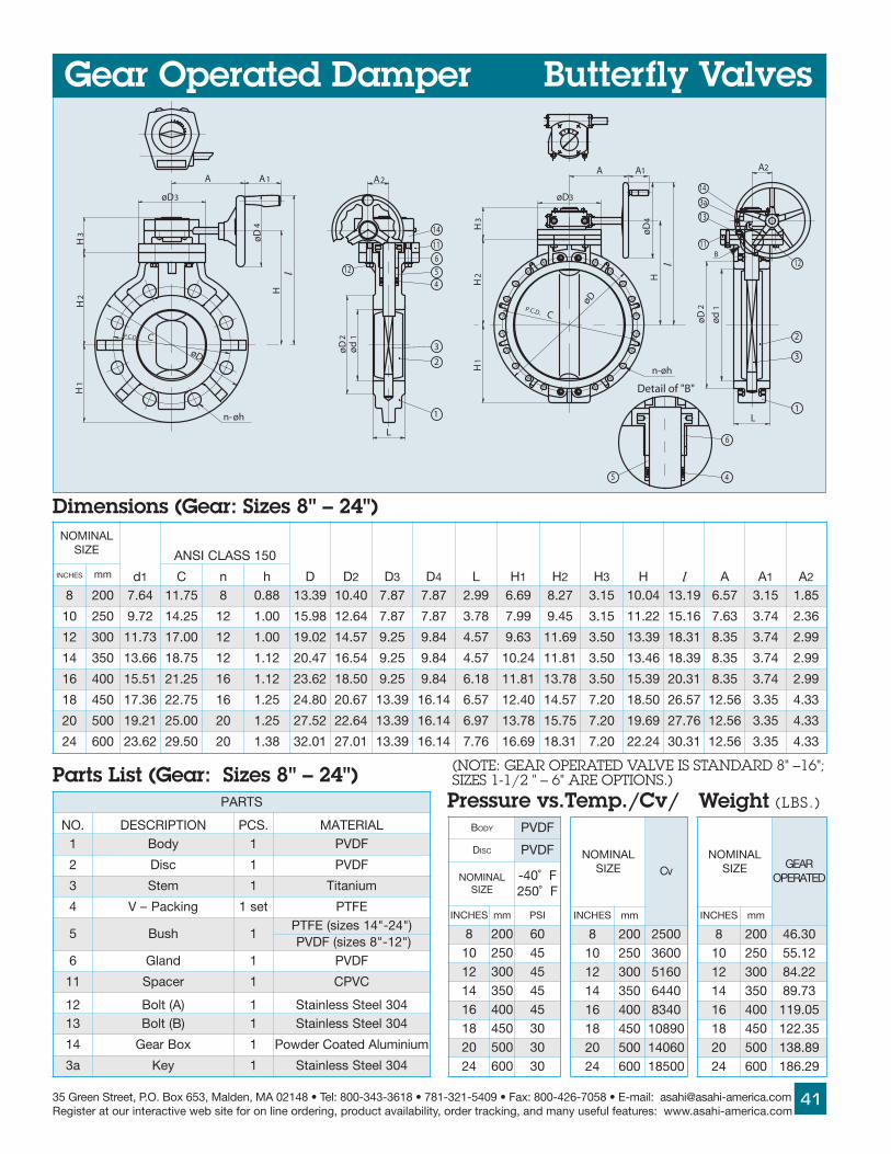
35 Green Street, P.O. Box 653, Malden, MA 02148 • Tel: 800-343-3618 • 781-321-5409 • Fax: 800-426-7058 • E-mail: [email protected] at our interactive web site for on line ordering, product availability, order tracking, and many useful features: www.asahi-america.com
41
4
6
øD
P.C.D. C
n-øh
5
H
øD3
A
4ø
D
l
L
øD
2
ød
1
2
3
11B
13
3a
14
A2
12
H1
n-
øD
øh
H2
3H
P.C.D. C
øD3
A
Hl
øD
4
A1
3øD ød
L
1
2
2
12
45
A2
11
14
1
1
1A
1H
2H
H3
6
Detail of "B"
Gear Operated Damper Butterfly Valves
Parts List (Gear: Sizes 8" – 24")
Dimensions (Gear: Sizes 8" – 24")LANIMON
EZIS
d1
051SSALCISNA
D D2 D3 D4 L H1 H2 H3 H l A A1 A2SEHCNI mm C n h8 002 46.7 57.11 8 88.0 93.31 04.01 78.7 78.7 99.2 96.6 72.8 51.3 40.01 91.31 75.6 51.3 58.1
01 052 27.9 52.41 21 00.1 89.51 46.21 78.7 78.7 87.3 99.7 54.9 51.3 22.11 61.51 36.7 47.3 63.2
21 003 37.11 00.71 21 00.1 20.91 75.41 52.9 48.9 75.4 36.9 96.11 05.3 93.31 13.81 53.8 47.3 99.2
41 053 66.31 57.81 21 21.1 74.02 45.61 52.9 48.9 75.4 42.01 18.11 05.3 64.31 93.81 53.8 47.3 99.2
61 004 15.51 52.12 61 21.1 26.32 05.81 52.9 48.9 81.6 18.11 87.31 05.3 93.51 13.02 53.8 47.3 99.2
81 054 63.71 57.22 61 52.1 08.42 76.02 93.31 41.61 75.6 04.21 75.41 02.7 05.81 75.62 65.21 53.3 33.4
02 005 12.91 00.52 02 52.1 25.72 46.22 93.31 41.61 79.6 87.31 57.51 02.7 96.91 67.72 65.21 53.3 33.4
42 006 26.32 05.92 02 83.1 10.23 10.72 93.31 41.61 67.7 96.61 13.81 02.7 42.22 13.03 65.21 53.3 33.4
Pressure vs.Temp./Cv/ Weight (LBS.)STRAP
.ON NOITPIRCSED .SCP LAIRETAM1 ydoB 1 FDVP
2 csiD 1 FDVP
3 metS 1 muinatiT
4 gnikcaP–V tes1 EFTP
5 hsuB 1)"42-"41sezis(EFTP)"21-"8sezis(FDVP
6 dnalG 1 FDVP
11 recapS 1 CVPC
21 )A(tloB 1 403leetSsselniatS31 )B(tloB 1 403leetSsselniatS
41 xoBraeG 1 muinimulAdetaoCredwoP
a3 yeK 1 403leetSsselniatS
(NOTE: GEAR OPERATED VALVE IS STANDARD 8" –16"; SIZES 1-1/2 " – 6" ARE OPTIONS.)
LANIMONEZIS RAEG
DETAREPO
SEHCNI mm
8 002 03.6401 052 21.5521 003 22.4841 053 37.9861 004 50.91181 054 53.22102 005 98.83142 006 92.681
LANIMONEZIS vC
SEHCNI mm
8 002 005201 052 006321 003 061541 053 044661 004 043881 054 0980102 005 0604142 006 00581
B YDO FDVP
D CSI FDVP
LANIMONEZIS
F˚04-F˚052
SEHCNI mm ISP
8 002 0601 052 5421 003 5441 053 5461 004 5481 054 0302 005 0342 006 03
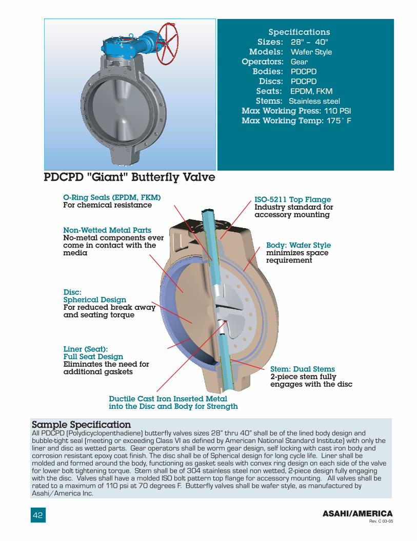
ASAHI/AMERICARev. C 03-05
42
PDCPD "Giant" Butterfly Valve
ISO-5211 Top FlangeIndustry standard foraccessory mounting
O-Ring Seals (EPDM, FKM)For chemical resistance
Non-Wetted Metal PartsNo-metal components evercome in contact with themedia
Body: Wafer Styleminimizes spacerequirement
Stem: Dual Stems2-piece stem fullyengages with the disc
Disc:Spherical DesignFor reduced break awayand seating torque
Liner (Seat):Full Seat DesignEliminates the need foradditional gaskets
Ductile Cast Iron Inserted Metalinto the Disc and Body for Strength
Sample SpecificationAll PDCPD (Polydicyclopenthadiene) butterfly valves sizes 28” thru 40” shall be of the lined body design andbubble-tight seal (meeting or exceeding Class VI as defined by American National Standard Institute) with only theliner and disc as wetted parts. Gear operators shall be worm gear design, self locking with cast iron body andcorrosion resistant epoxy coat finish. The disc shall be of Spherical design for long cycle life. Liner shall bemolded and formed around the body, functioning as gasket seals with convex ring design on each side of the valvefor lower bolt tightening torque. Stem shall be of 304 stainless steel non wetted, 2-piece design fully engagingwith the disc. Valves shall have a molded ISO bolt pattern top flange for accessory mounting. All valves shall berated to a maximum of 110 psi at 70 degrees F. Butterfly valves shall be wafer style, as manufactured byAsahi/America Inc.
SpecificationsSizes: 28" – 40"
Models: Wafer StyleOperators: Gear
Bodies: PDCPDDiscs: PDCPD
Seats: EPDM, FKM Stems: Stainless steelMax Working Press: 110 PSIMax Working Temp: 175˚ F

35 Green Street, P.O. Box 653, Malden, MA 02148 • Tel: 800-343-3618 • 781-321-5409 • Fax: 800-426-7058 • E-mail: [email protected] at our interactive web site for on line ordering, product availability, order tracking, and many useful features: www.asahi-america.com
43
Parts List
Dimensions (Inches)
CvValues
Pres. vs. Temp(Non-shock)
PDCPD "Giant" Butterfly Valve
Dimensions (mm)
LANIMONEZIS
vC
SEHCNI mm ˚03 ˚06 ˚09
82 007 006,3 000,31 000,23
23 008 002,4 000,71 000,34
63 009 006,5 000,22 000,55
04 0001 000,7 000,62 000,07
LANIMONEZIS
.pmeTsVerusserP thgieW)sbL(
SEHCNI mm F˚021-03 F˚571-12182 007 ISP011 ISP07 04823 008 ISP011 ISP07 510163 009 ISP011 ISP07 512104 0001 ISP011 ISP07 0381
STRAP
.ON NOITPIRCSED .SCP LAIRETAM1 ydoB 1 DPCDP2 csiD 1 DPCDP3 taeS 1 MKF MDPE,4 )A(gniR-O 11 ,MKF MDPE5 )B(gniR-O 3 ,MKF MDPE6 )C(gniR-O 1 RBN7 )D(gniR-O 1 RBN8 )A(metS 1 403leetSsselniatS9 metS )B( 1 403leetSsselniatS01 )A(yeK 1 leetSnobraC11 )B(yeK 1 leetSnobraC
21 hsuB 2 )reniLMDPEroF(gnitsaCeznorB)reniLMKFroF(FDVP
31 )A(teksaG 1 teehSsanoN41 redloHmetS 1 403leetSsselniatS51 )A(tloB 6 403leetSsselniatS61 xoBraeG 1 )taoCyxopEhtiW002CF(norItsaC71 )A(gniRtsurhT 1 EPEMHU81 )B(tloB 8 403leetSsselniatSa3 gniRnoitazilibatS 2 403leetSsselniatSa1 ydoBfolateMdetresnI 1 )054DCF(norItsaCb1 csiDfolateMdetresnI 1 )054DCF(norItsaC
LANIMONEZIS
d
051/521SSALCISNA
B D 1D 2D 3D L 1A 2A 1H 2H 3H H I
raeGxoB
ledoMC n h 1h MSEHCNI mm82 007 83.62 00.43 42 83.1 4 4/1-1 83.1 45.63 29.92 87,31 31.71 11.8 38.51 22.11 91.32 32.32 67.9 79.62 13.53 01FRB23 008 13.03 05.83 42 26.1 4 2/1-1 83.1 43.14 52.43 87,31 31.71 54.9 38.51 22.11 73.42 14.42 67.9 51.82 05.63 01FRB63 009 52.43 57.24 82 26.1 4 2/1-1 83.1 89.54 05.83 87,31 00.52 54.9 38.51 22.11 27.72 67.72 67.9 05.13 00.44 01FRB04 0001 91.83 57.24 23 26.1 4 2/1-1 56.1 00.05 25.24 11.81 00.52 18.11 02.22 35.9 94.92 25.92 93.01 72.33 55.54 02FRB
LANIMONEZIS
d
01NPNID
B D 1D 2D 3D L 1A 2A 1H 2H 3H H I
raeGxoB
ledoMC n h 1h MSEHCNI mm82 007 076 048 02 03 4 72M 53 829 067 053 534 602 204 582 985 095 842 586 798 01-FRB23 008 077 059 42 33 4 03M 53 4301 078 053 534 042 204 582 916 026 842 517 729 01-FRB63 009 078 0501 42 33 4 03M 53 8611 879 053 536 042 204 582 407 507 842 008 2111 01-FRB04 0001 079 0611 42 63 4 33M 24 2621 0801 064 536 003 465 242 947 057 462 548 7511 02-FRB
17
Details:Z
H1
H2
H3
HI
D3
D2
A1 3.62 A2
P.C.D.CD
d
n- h
Z
Length:B
(92mm)
L
D1
n1- M
11
16
17
188
12
3a
10
3
2
2a
1a
1
9
13
14
15
7
5
6
4

ASAHI/AMERICARev. C 03-05
44
Butterfly Valve Options
TANDEM ELECTRIC
TANDEM PNEUMATIC
Tandem ValvesAsahi/America's patented, electric and pneumatictandem operated butterfly valves are primarily usedfor three-way or diverting applications of slurries ormedia with suspended particles. Valves can bemounted on the straight run of the "T" or anycombination of the branches. This tandemconfiguration can also be used for simultaneouscycling of the valves in parallel lines.
AccessoriesCHAIN OPERATORSThese operators are used for valves in overheadlocations. They can only be used with gear operatedvalves.
CHAIN OPERATORBUTTERFLYVALVE
GEAROPERATOR
CHAIN
OPERATING NUTSOperating nuts are available in 2" square or "T"configurations. They are used for remote operationof a valve with an extended wrench.
2" SQUAREOPERATING
NUT
TRAVELSTOP
VERTICAL POSITION
Limit switches are used for remote positionindication with the use of lights or for sequencing ofother equipment.
Limit Switches
LEVER OPERATOR
GEAR OPERATOR
LIMIT SWITCH"CLOSE"
LIMIT SWITCH"OPEN"
"OPEN/CLOSE"INDICATOR
LIMIT SWITCH
For end-of-line applications, mounted with a singleflange or for use as a blocking valve, where eitherside can be unbolted, and the system pressure canstill be maintained on the other side.
Lug Style ValveHORIZONTAL POSITION
PROVIDED BYCUSTOMER

35 Green Street, P.O. Box 653, Malden, MA 02148 • Tel: 800-343-3618 • 781-321-5409 • Fax: 800-426-7058 • E-mail: [email protected] at our interactive web site for on line ordering, product availability, order tracking, and many useful features: www.asahi-america.com
45
Butterfly Valve Stem Extensions
STYLE LBF-A(TWO PIECE, STEM & HOUSING)
SHUT
OPENB
A
B
A
STYLE GBF-A (TWO PIECE, STEM & HOUSING)
BA
STYLE GBF-B (ONE PIECE, NON-SUPPORTED)
STYLE GBF-C (ONE PIECE, NON-SUPPORTED)
A
BB
AC
STYLE LBF-B(ONE PIECE, NON-SUPPORTED)
Two-Piece Stem andHousingFor submerged or buriedapplications. PVC housingprotects stem extensionsfrom agressive environ-ments. Epoxy coated carbonsteel housing is also available,which is designed to meetlandfill specifications.
Single Stem ExtensionsValve handle can be extended away from the valvefor out-of-reach locations.
PATENTED WALL SUPPORT

ASAHI/AMERICARev. C 03-05
46
5.449.25
9.06
H
H1
8.22
Engineering Data
Series 92 Electric Actuators
• Brushless, capacitor-run motors (AC models)• Integral thermal overload protection with auto-
reset (AC models)• Permanently lubricated gear train• Duty cycle 100% for high cycle applications• Combination NEMA 4X, 7 and 9 enclosure with
thermally bonded powder coating/304 ss trim• ISO bolt circle• Two 1/2" NPT conduit ports prevent inter-
ference between control and power signals• Declutchable manual override• Standard travel-stop limit switches can
simultaneously be used for indicator lights• Highly visible position indicator
Standard Features (Sizes 1-1/2" – 8")
Options• Failsafe battery pack• Extra limit switches• Feedback potentiometer• Heater and thermostat (to -40º F)• Positioner: 4–20mA or 0–10Vdc input• 4–20mA output position transmitter• Voltages: 220 Vac, 24 Vac, 12 Vac, 24 Vdc, 12 Vdc• Mechanical brake eliminates seating oscillation• Bus systems
AC Wiring (For 115 Vac and 220 Vac only)
M
SEE IMPORTANT NOTE
ACTUATOR SHOWN IN COUNTER-CLOCKWISE EXTREME OF TRAVEL, OR "OPEN" POSITION
LIGHTS ANDSWITCHES
CUSTOMER PROVIDED
YELL
OW
1BLA
CK
2WH
ITE
L1
3BLU
E
4 5BRO
WN
L2
6 7
SW2
NC
NC
SW1
NO
BLUE
NO
WHITE
VOLTSAC
8 9 10 11 12 1413 15 16
A
BLUE
WHITE
B
Electric Actuators Specifications
Series 92: Motor Type – Reversing, 1/4 turnsingle phase
Models – S92, A92, B92, C92 forsizes1-1/2" – 8" ;
Contact factory for sizes 10" – 24"Torque – 400 – 2000 in.-lbs.Voltage – 120 Vac, 50/60 HzMax Ambient Temp – 150˚ FSwitches – Two single pole, double
throw (15 Amp rating)
SERIES 92 ONTYPE 56 BUTTERFLY VALVE
Duty cycle shown above is for 115 Vacat ambient temperature.
HARDWARE
COUPLING
PPG BRACKET
HARDWARE
rotautcAledoM
euqroT).sbl-ni(
ytuDelcyC
elcyCemiT).ces(
thgieW).sbl(
warDpmA511caV
022caV
42caV
21caV
42cdV
21cdV
29S 004 001 01 0.01 05.0 4.0 0.3 0.2 0.4 0.229A 007 57 01 0.01 08.0 6.0 0.3 0.2 0.4 0.229B 0011 001 52 0.11 05.0 4.0 0.3 0.2 0.4 0.229C 0002 05 52 0.12 00.1 6.0 * * * *
NOTE TO WIRING DIAGRAM:1. EACH ACTUATOR MUST BEPOWERED THROUGH ITS OWNINDIVIDUAL SWITCH CON-TACTS TO AVOID CROSS FEED.2. MOTOR LEADS "A" AND "B"ARE REVERSED FOR B92 & C923. MOTOR HAS A THERMALPROTECTOR AS SHOWN BY MIN DIAGRAM. (115 AND 220 VACMODEL).4. IF 115 & 220 VAC MODELSARE PLC DRIVEN, OUTPUTCONTACTS OF PLC SHOULDBE RATED AT A MINIMUM OF1.5 TIMES REQUIRED INPUTVOLTAGE OF ACTUATOR.
Dimensions/Actuator Model
(Contact factory for sizesabove 8")
LANIMONEZIS
LEDOM H H1SEHCNI mm
1 2/1 04 29S 15.5 59.2
2 05 29S 57.5 72.3
2 2/1 56 29S 81.6 66.3
3 08 29S 64.6 49.3
4 001 29S 61.7 35.4
5 521 29A 64.8 00.5
6 051 29B 79.8 36.5
8 002 29C 52.11 07.6

35 Green Street, P.O. Box 653, Malden, MA 02148 • Tel: 800-343-3618 • 781-321-5409 • Fax: 800-426-7058 • E-mail: [email protected] at our interactive web site for on line ordering, product availability, order tracking, and many useful features: www.asahi-america.com
47
H
7.38
6.37
5.623.82
H
Engineering Data
SERIES 92 SERIES 94
Series 94 Electric Actuators
SpecificationsSeries 94: Motor Type – Reversing, 1/4 turn,
single phaseSizes – A94 for sizes 1-1/2" – 2"
B94 for sizes 2-1/2" – 4"Torque – 150 to 300 in-lbsVoltage – 120 Vac, 50/60 HzAmp Draw – For A94: .5 Amps
For B94: .80 AmpsMax Ambient Temp – 150˚ FSwitches – Two single pole, double
throw (15 Amp rating)
Electric Actuators
• Brushless, capacitor-run motors (AC models)• Integral thermal overload protection with auto-
reset (AC models)• Permanently lubricated gear train• Duty cycle 100% for high cycle applications• Corrosion-proof/weatherproof NEMA 4X
thermoplastic housing with stainless steel trim• ISO bolt circle• Two 1/2" NPT conduit ports prevent inter-
ference between control and power signals• Low in cost• Declutchable manual override• Standard travel-stop limit switches can
simultaneously be used for indicator lights• Visible position indicator
Standard Features (Sizes 1-1/2" – 4")
Options• Failsafe battery pack• Extra limit switches• Feedback potentiometer• Heater and thermostat (to -40º F)• Positioner: 4–20mA or 0–10 Vdc input signal• 4–20mA output position transmitter• Voltages: 220 Vac, 24 Vac, 12 Vac, 24 Vdc, 12 Vdc• Mechanical brake eliminates seating oscillation
Dimensions/Actuator Model
NOTE TO WIRING DIAGRAM:1. EACH ACTUATOR MUST BEPOWERED THROUGH ITS OWNINDIVIDUAL SWITCH CON-TACTS TO AVOID CROSS FEED.2. WIRING AS SHOWN IS FORA94 AND B94 MOTOR.3. MOTOR HAS A THERMALPROTECTOR AS SHOWN BY MIN DIAGRAM. (115 AND 220 VACMODEL).4. IF 115 & 220 VAC MODELSARE PLC DRIVEN, OUTPUTCONTACTS OF PLC SHOULDBE RATED AT A MINIMUM OF1.5 TIMES REQUIRED INPUTVOLTAGE OF ACTUATOR.
rotautcAledoM
euqroT)sbl-ni(
ytuDelcyC
elcyCemiT)ces(
thgieW)sbl(
warDpmA
511caV
022caV
42caV
21caV
42cdV
21cdV
49A 051 001 5 5.3 05.0 4.0 0.4 0.2 0.4 0.2
49B 003 57 5 5.3 08.0 6.0 0.4 0.2 0.4 0.2
AC Wiring (For 115 Vac and 220 Vac only)
M
SEE IMPORTANT NOTE
ACTUATOR SHOWN IN COUNTER-CLOCKWISE EXTREME OF TRAVEL, OR "OPEN" POSITION
LIGHTS ANDSWITCHES
CUSTOMER PROVIDED
YELL
OW
1BLA
CK
2WH
ITE
L1
3BLU
E
4 5BRO
WN
L2
6 7
SW2
NC
NC
SW1
NO
BLUE
NO
WHITE
VOLTSAC
8 9 10 11 12 1413 15 16
A
BLUE
WHITE
B
SERIES 94 ONTYPE 56 BUTTERFLY VALVES
Duty cycle shown above is for 115 Vacat ambient temperature.
LANIMONEZIS
LEDOM H H1SEHCNI mm
2/11 04 49A 15.5 59.2
2 05 49A 57.5 72.3
2/12 56 49B 81.6 66.3
3 08 49B 64.6 49.3
4 001 49B 61.7 35.4
HARDWARE
COUPLING
PPG BRACKET
HARDWARE

ASAHI/AMERICARev. C 03-05
48
C1 C2
OPTIONSWITH OPTIONS
C
A
H
H1
B
Pneumatically Actuated Butterfly Valves
SERIES 79ON TYPE 56BUTTERFLYVALVES
LANIMONEZIS .ONLEDOM
RIA-RIA.ONLEDOM
GNIRPS-RIA H H1
A B C C1 C2
A-A S-A A-A S-A A-A S-A A-A S-A A-A S-ASEHCNI mm
2/11 04 NP97PB NSP97PC 15.5 59.2 04.4 00.5 29.4 47.8 37.1 71.2 66.5 98.5 14.1 58.1
2 05 NP97PB NSP97PC 57.5 52.3 04.4 00.5 29.4 47.8 37.1 71.2 66.5 98.5 14.1 58.1
2/12 08 NP97PB NSP97PC 81.6 66.3 04.4 00.5 29.4 47.8 37.1 71.2 66.5 98.5 14.1 58.1
3 001 NP97PC NSP97PD 64.6 49.3 00.5 94.6 00.7 05.11 71.2 46.2 98.5 84.6 58.1 63.2
4 001 NP97PC NSP97PD 61.7 35.4 00.5 94.6 00.7 05.11 71.2 46.2 98.5 84.6 58.1 63.2
5 521 NP97PC NSP97E 64.8 00.5 00.5 45.8 00.7 05.81 71.2 45.3 98.5 74.7 58.1 32.3
6 051 NP97PD NSP97E 79.8 36.5 94.6 45.8 12.9 05.81 46.2 45.3 84.6 74.7 63.2 32.3
8 002 NP97E NSP97E 72.11 96.6 45.8 45.8 21.21 05.81 45.3 45.3 74.7 74.7 32.3 32.3
01 052 NP97E NSP97F 64.21 99.7 45.8 62.11 21.21 82.52 45.3 31.4 74.7 60.8 32.3 87.3
21 003 NP97F NSP97G 96.41 35.9 62.11 70.31 64.61 23.72 31.4 02.5 60.8 50.9 87.3 67.4
41 053 NP97G NSP97K 18.41 42.01 70.31 35.61 36.02 38.23 02.5 78.7 50.9 27.11 67.4 61.7
61 004 NP97G NSP97K 87.61 18.11 70.31 35.61 36.02 38.23 02.5 78.7 50.9 27.11 67.4 61.7
81 054 NP97G NSP97K 75.71 04.21 70.31 35.61 36.02 38.23 02.5 78.7 50.9 27.11 67.4 61.7
02 005 NP97G NSP97K 57.81 87.31 70.31 35.61 36.02 38.23 02.5 78.7 50.9 27.11 67.4 61.7
42 006 NP97G NSP97K 13.12 20.61 70.31 35.61 36.02 38.23 02.5 78.7 50.9 27.11 67.4 61.7
Dimensions (Sizes 1-1/2" – 24")
Standard Features (Sizes 1-1/2" – 24")• Recommended air supply pressure:
80 psi (filtered air)maximum air supply pressure 120 psi
• Double piston, double rack and pinion design(Polyamid-Nylon 66)
• Air-to-Air (double acting) or Air-to-Spring (springreturn failsafe) models
• Position indication through highly visibleindicator knob
• Manual override easily employed by insertingwrench onto flats of stem. A declutchable gearoperator is required on Air-to-Air sizes 8" andabove and on all Air-to-Spring sizes
• Actuator shaft 303 stainless steel-See page 22
• Air-to-Air actuators up to 6" and Air-to- Springactuators up to 4" have PEG (polyamide glass-filled) plastic enclosures. Larger sizes featurealuminum bodies with Cataphoresis and Rilsan
coating inside and outside.
• Concentric spring sets allow for consistentoutput torque.
• ISO and NAMUR mounting dimensions allow forvalve accessory mounting
• All models are corrosion resistant to handle themost aggressive applications.
Options• Solenoids in various NEMA enclosure ratings
and voltages are supplied with muffler speedcontrol and push button override
• Double limit switches in NEMA IV and VII enclosures• Positioner for modulating service: 4–20 mA or
3 –15 psi control signal (requiring no solenoid)• 316 stainless steel actuator body• Bus systems

35 Green Street, P.O. Box 653, Malden, MA 02148 • Tel: 800-343-3618 • 781-321-5409 • Fax: 800-426-7058 • E-mail: [email protected] at our interactive web site for on line ordering, product availability, order tracking, and many useful features: www.asahi-america.com
49
OPEN
1/2"NPT
1/4"NPT2HOLES
1/2"NPT
F: DIA.K: THREADL: DEPTH4 HOLES
A A
BEACON
OPEN
OPEN
OPEN
VIEW A-A
3D VIEW
B
C
6.03
E
J
C
G
WESTLOCK ® K-10 POSITIONER
B
ECKARDT POSITIONER
CAM STOP
SWITCH ASSEMBLY SWITCH ASSEMBLYWITH SOLENOID
2.3
2.9
2.6
0.94
5.4
5.43.3
H
7.5
INSTRUMENT AIRSUPPLY
4.8
A
1.28
C
B
Dimensions (IN.) ACTUATOR / LIMIT SWITCH Dim. (IN.) ACT./POSITIONER
Pneumatic Actuator and Options
Air CONSUMPTION
ROTAUTCAEZIS B C
EF H G J K LA-A S-A
P97PB 61.2 41.3 29.4 68.5 79.1 14.1 37.1 04.4 mm6 05.
P97PC 61.2 18.3 00.7 47.8 67.2 58.1 71.2 00.5 mm8 26.
P97PD 61.2 51.5 12.9 94.11 67.2 63.2 46.2 94.6 mm8 57.
P97E 61.2 90.7 21.21 05.81 20.4 32.3 45.3 45.8 mm01 97.
P97F 59.2 68.8 64.61 82.52 29.4 87.3 31.4 62.11 mm21 97.
P97G 59.2 17.01 36.02 23.72 15.5 67.4 02.5 70.31 mm61 89.
P97K 59.2 69.41 A/N 38.23 05.6 61.7 78.7 35.61 4/3 01- 41.1
ROTAUTCAEZIS B C
E A
A-A S-A 51-3isp
02-4Am
P97PB 61.2 41.3 29.4 68.5 82.2 51.4
P97PC 61.2 18.3 00.7 47.8 82.2 51.4
P97PD 61.2 51.5 12.9 94.11 82.2 51.4
P97E 61.2 90.7 21.21 05.81 82.2 51.4
P97F 59.2 68.8 64.61 82.52 82.2 51.4
P97G 59.2 17.01 36.02 23.72 82.2 51.4
P97K 59.2 69.41 A/N 38.23 82.2 51.4
LEDOMREBMUN
CIBUCSEHCNI
P97PB 0.9
P97PC 5.91
P97PD 0.25
P97E 0.521
P97F 0.342
P97G 0.046
P97K 0.4601

ASAHI/AMERICARev. C 03-05
50
Standard Features• Flanged (ANSI) face-to-face dimensions are
equivalent to most commonly used metallic valves• Rugged body and bonnet are of solid thermo-
plastic for maximum corrosion resistance• Uniquely designed body and bonnet together with
diaphragms of new sealing designs by computerdynamic analysis for superior sealing
• Weir design for excellent throttling• Bubble-tight sealing, even in applications such as
slurries or suspended particles• Bonnet seals to protect internals from corrosive
environments• Built-in travel stop to prevent over-tightening or
compressive strain on diaphragm• Integrally molded bottom stand for simple yet
firm panel mounting• Indicator at the top for indication of valve
position and prevention of over-tightening• PVDF Gas Barrier, which protects EPDM backing
from gas permeation, is standard for PVDF valves
• Low profile• 1/2" - 2" in bayonet structure to connect
compressor and diaphragm – easy diaphragmreplacement
Options• PVDF gas barrier for aggressive fluids• 2" square nut• “T” operating nut for remote operation• Stem extensions (single and two-piece design)• Locking device for tamper-proofing• Manual limit switches for remote position
indication by lights or for sequencing of otherequipment
• Pneumatic (all sizes) or electric (to 3") actuation
Sizes:Body Materials:
Bonnet Materials:Diaphragms:
Specifications1/2" – 4"PVC, CPVC, PP and PVDFPVC, PP, PPG and PVDFEPDM and PTFEAlso available in othermaterials such as Nitrile,FKM, Butyl, Hypalon®† andNeoprene®†
††††† Trademarks of E. I. du Pont de Nemours and CompanyType 14 Flanged Diaphragm
STRAP
.ON NOITPIRCSED .SCP LAIRETAM1 ydoB 1 FDVP,PP,CVPC,CVP
2 tennoB 1 FDVP,PP,GPP,CVP
3 mgarhpaiD 1 srehtO,EFTP,MDPE
a3 tresnIlateMmgarhpaiD 1 403leetSsselniatS
4 *noihsuC 1 MDPE
5 *reirraBsaGFDVP 1 FDVP
6 rosserpmoC 1 FDVP
7 tnioJ 1 403leetSsselniatS8 metS 1 yollAreppoC
9 eveelS 1 yollAreppoC
01 leehWdnaH 1 PP
11 revoCeguaG 1 CP
21 etalPemaN 1 CVP
31 epyTCgniRgniniateR 1 403leetSsselniatS
41 )A(gniR-O 1 MDPE
51 )B(gniR-O 1 MDPE
61 )A(gniRtsurhT 1 EPWMHU
71 )B(gniRtsurhT 1 EPWMHU
81 rehsaW,tuN,tloB steS4 403leetSsselniatS
02 )A(reppotS 1 yollAreppoC
12 wercS 1 403leetSsselniatS
* Used on PTFE diaphragm
Parts Type 14 Flanged (Sizes 1/2" – 2")
PVC
PVDF
PP
CPVC/PP

25135 Green Street, P.O. Box 653, Malden, MA 02148 • Tel: 800-343-3618 • 781-321-5409 • Fax: 800-426-7058 • E-mail: [email protected] at our interactive web site for on line ordering, product availability, order tracking, and many useful features: www.asahi-america.com
172
D1
H2
1
18
t
L
n- øh
l
Cød
P.C
.D.
øD
3a
3
7
6
H1
H
11
10øD2
20
89
15
16
14
13
21
12
Detail of holes forinsert metal fittings
S
2-øS1 Depth S2
4
3
In case of PVDF bodyand PTFE diaphragm
5
4
3
In case of PTFE diaphragm
Y Y
Y-Y
LIFT
Diaphragm ValvesType 14 Flanged
Dimensions Type 14 Flanged (Sizes 1/2" – 2")
Pressure vs. Temperature PSI, WATER, NON-SHOCK
LANIMONEZIS CV
.TW.GLF).COS(
SEHCNI mm
2/1 51 8.4 05.14/3 02 3.5 08.1
1 52 5.8 04.21 4/1 23 0.11 01.31 2/1 04 62 02.6
2 05 34 00.8
LANIMONEZIS
CVP CVPC PP FDVP
SMGARHPAIDLLA SMGARHPAIDLLA SMGARHPAIDLLA MGARHPAIDEFTP
F0̊3F5̊01
F6̊01F0̊41
F0̊3F5̊01
F6̊01F0̊41
F1̊41F5̊71
F6̊71F5̊91
F5̊-F5̊01
F6̊01F0̊41
F1̊41F5̊71
F6̊71F5̊91
F0̊4-F0̊41
F1̊41F5̊71
F6̊71F0̊12
F1̊12F0̊52SEHCNI mm
2/1 51 051 001 051 511 58 04 051 511 58 07 051 021 59 074/3 02 051 001 051 511 58 04 051 511 58 07 051 021 59 07
1 52 051 001 051 511 58 04 051 511 58 07 051 021 59 071 4/1 23 051 001 051 511 58 04 051 511 58 07 051 021 59 071 2/1 04 051 001 051 511 58 04 051 511 58 07 051 021 59 07
2 05 051 001 051 511 58 04 051 511 58 07 051 021 59 07
Cv Values/Wt.
LANIMONEZIS
d
051SSALCISNA
D1 D2 l L t H H1 H2 S S1 S2SEHCNI mm C D n h2/1 51 36.0 83.2 05.3 4 26.0 06.2x31.2 64.3 93.0 52.4 34.0 90.4 93.3 94.0 89.0 82.0 15.0
4/3 02 97.0 57.2 88.3 4 26.0 06.2x31.2 64.3 93.0 88.5 15.0 71.4 64.3 75.0 89.0 82.0 15.0
1 52 89.0 21.3 52.4 4 26.0 51.3x46.2 64.3 74.0 88.5 95.0 73.4 66.3 37.0 89.0 82.0 15.0
1 4/1 23 62.1 05.3 26.4 4 26.0 51.3x46.2 64.3 74.0 83.6 36.0 75.4 28.3 98.0 89.0 82.0 15.0
1 2/1 04 75.1 88.3 00.5 4 26.0 52.4x52.4 41.6 38.0 49.6 36.0 79.6 76.5 80.1 77.1 53.0 95.0
2 05 50.2 57.4 00.6 4 57.0 48.4x48.4 41.6 89.0 49.7 97.0 25.7 22.6 24.1 77.1 53.0 95.0

ASAHI/AMERICARev. C 03-05
52
S
94
H2
1
L
t n- øh
l
øD1
P.C
.D.ø
d C øD
903a
3
1a
H1
18
2
88
10øD2
118a20
89
158
179
6 H
16
1314
12
4
Detail of holes forinsert metal fittings
2-øS1 Depth S2
3
In case of PVDF bodyand PTFE diaphragm
4
3
5
In case of PTFE diaphragm
Y Y
Y-Y
LIFT
LANIMONEZIS
d
051SSALCISNA
D1 D2 l L
t
H H1 H2 S S1 S2C D n hCVPCVPC
PPFDVPSEHCNI mm
2 2/1 56 46.2 05.5 00.7 4 57.0 98.6 66.8 43.1 48.9 78.0 19.0 74.01 04.7 04.2 53.3 34.0 97.0
3 08 70.3 00.6 05.7 8 57.0 19.7 66.8 56.1 83.01 78.0 19.0 20.11 59.7 84.2 49.3 95.0 01.1
4 001 49.3 05.7 00.9 8 57.0 94.9 21.01 79.1 49.21 78.0 49.0 59.21 94.9 70.3 27.4 95.0 01.1
Dimensions Type 14 Flanged (Sizes 2-1/2" – 4")
LANIMONEZIS
CVP CVPC PP FDVP
SMGARHPAIDLLA SMGARHPAIDLLA SMGARHPAIDLLA MGARHPAIDEFTP
F0̊3F5̊01
F6̊01F0̊41
F0̊3F5̊01
F6̊01F0̊41
F1̊41F5̊71
F6̊71F5̊91
F5̊-F5̊01
F6̊01F0̊41
F1̊41F5̊71
F6̊71F5̊91
F0̊4-F0̊41
F1̊41F5̊71
F6̊71F0̊12
F1̊12F0̊52SEHCNI mm
2 2/1 56 051 511 051 021 59 58 051 021 59 58 051 511 58 073 08 051 511 051 021 59 58 051 021 59 58 051 511 58 074 001 051 511 051 021 59 58 051 021 59 58 051 511 58 07
Pressure vs. Temperature PSI, WATER, NON-SHOCK
LANIMONEZIS CV
.TW.GLF).SBL(
SEHCNI mm
2 2/1 56 58 33.413 08 511 46.714 001 581 08.52
Cv Values/Wt.
• After replacing diaphragm, do not tighten boltsfor bonnet and body with diaphragm in theclosed position. Excessive force coulddamage bonnet or body.
• Full vacuum rated 1/2" through 2 1/2"
Diaphragm ValvesType 14 Flanged
• Vacuum Rating
(1) Rubber Diaphragms (2) PTFE Diaphragm
3" - 25.59" - 9.84" 4" -19.69" - 3.94"• Never remove valve from pipeline under
pressure.• Always wear protective gloves and goggles.
Caution

25335 Green Street, P.O. Box 653, Malden, MA 02148 • Tel: 800-343-3618 • 781-321-5409 • Fax: 800-426-7058 • E-mail: [email protected] at our interactive web site for on line ordering, product availability, order tracking, and many useful features: www.asahi-america.com
Sample SpecificationAll TYPE 14 flanged diaphragm valves shall be of solidthermoplastic construction for body and bonnet withmolded flanged ends. The valves shall come standardwith a position indicator, travel stop (to prevent over-tightening) and bonnet o-ring sealing arrangement.The valve shall be weir type with a square bonnet bodysealing design and bayonet connection diaphragm(1/2"– 2") or round bonnet body sealing design andthreaded stud diaphragm connection (2-1/2"–4”). AllPTFE diaphragms shall accept the installation of aPVDF gas barrier between the layers of EPDM andPTFE for aggressive chemical service. The face-to-facedimensions shall conform to TYPE G. PVC conform-ing to ASTM D1784 Cell Classification 12454-A, CPVCconforming to ASTM D1784 Cell Classification23567-A, PP conforming to ASTM D4101 CellClassification PP0210B67272, PPG (Bonnet Only)conforming to ASTM D4101 Cell ClassificationPP0110M20A21130, and PVDF conforming to ASTMD3222 Cell Classification Type II. PVC, CPVC, PP andPVDF shall be rated to 150 psi for elastomeric andPTFE diaphragms at 70 degrees F., as manufacturedby Asahi/America, Inc.
STRAP
.ON NOITPIRCSED .SCP LAIRETAM1 ydoB 1 FDVP,PP,CVPC,CVP
2 tennoB 1 FDVP,PP,GPP,CVP
3 mgarhpaiD 1 srehtO,EFTP,MDPE
a3 tresnIlateMmgarhpaiD 1 403leetSsselniatS
4 *noihsuC 1 MDPE
5 *reirraBsaGFDVP 1 FDVP
6 rosserpmoC 1 FDVP
8 metS 1 yollAreppoCa8 doRgnitacidnI 1 403leetSsselniatS
9 eveelS 1 yollAreppoC
01 leehWdnaH 1 PP
11 revoCeguaG 1 CP
21 etalPemaN 1 CVP
31 epyTCgniRgniniateR 1 403leetSsselniatS
41 )A(gniR-O 1 MDPE
51 )B(gniR-O 1 MDPE
61 )A(gniRtsurhT 1 EPWMHU
71 )B(gniRtsurhT 1 EPWMHU
81 rehsaW,tuN,tloB steS4 403leetSsselniatS
02 )A(reppotS 1 yollAreppoC
88 elppiNesaerG 1 yollAreppoC
98 niProsserpmoC 1 403leetSsselniatS
09 tuN,tloBdutS steS4 srehtO,403leetSsselniatS
49 rosserpmoCfolateM 1 403leetSsselniatS
a1 tuNdetresnI 4403leetSsselniatS 1
yollAreppoC 2
Parts Type 14 Flanged (2-1/2" – 4")Diaphragm ValvesType 14 Flanged
TroubleshootingWhat if fluid leaks when valve is fully closed?
1. Travel stop not set correctly. Adjust it per theAsahi Operation and Maintenance manual.
2. Solids build up inside valve. Clean inside,including weir and diaphragm.
3. Diaphragm and/or weir are worn or damaged.Change the part(s).
What if valve cannot be fully opened?
1. Diaphragm is not properly engaged withcompressor. Check engagement per Operationand Maintenance manual.
What if fluid leaks to atmosphere?
1. Bonnet bolts not properly torqued. Retorqueaccording to Operation and Maintenancemanual.
2. Line pressure exceeds maximum recommendedline pressure. Check or reduce system linepressure.
3. Diaphragm has ruptured or has been chemicallyattacked. Replace diaphragm.
* Used on PTFE diaphragm1 Used for PVC body2 Used for PVC, CPVC, PP bodies

ASAHI/AMERICARev. C 03-05
54
Sizes:Body Materials:
Bonnet Materials:End Connectors:
Diaphragms:
Specifications1/2" – 2"PVC, CPVC, PP and PVDFPVC, PP, PPG and PVDFPVC, CPVC: IPS Soc. or Thr'dPP, PVDF: IPS & Metric(DIN)Socket, Threaded, ButtEPDM and PTFEAlso available in othermaterials such as Nitrile,FKM, Butyl, Hypalon®† andNeoprene®†
††††† Trade marks of E. I. du Pont de Nemours and CompanyType 14 True Union Diaphragm
Parts Type 14 True Union (1/2" – 2")• True Union design permits installation or repairs
without expanding pipeline• Rugged square body and bonnet are of solid
thermoplastic for maximum corrosionresistance
• Uniquely designed body and bonnet togetherwith diaphragms of new sealing designsby the state-of-the-art computer aided analysisfor superior sealing
• Weir design for excellent throttling
• Fully vacuum rated
• Bubble-tight sealing, even in applications such asslurries or suspended particles
• Bonnet seals to protect internals fromcorrosive environments
• Adjustable travel stop to prevent diaphragmfrom being over-tightened
• Bayonet structure to connect compressor anddiaphragm for quick maintenance
• Integrally molded bottom stand for simple yetfirm panel mounting
• Indicator at the top for valve position
• PVDF gas barrier, which protects EPDMbacking cushion from gas permeation, isstandard for PVDF valves
• Low profile
Standard Features
• PVDF gas barrier for PVC, CPVC and PP valves• 2” square or “T” operating nuts for remote
operation• Stem extensions• Locking device for tamper-proofing
Options• Pneumatic or electric actuation• Manual limit switches for remote position
indication by lights or for sequencing of otherequipment
* Used for PTFE diaphragm** Used for CPVC body, threaded end, 1/2" through 1"
STRAP
.ON NOITPIRCSED .SCP LAIRETAM1 ydoB 1 FDVP,PP,CVPC,CVP
2 tennoB 1 FDVP,PP,GPP,CVP
52 rotcennoCdnE 2 FDVP,PP,CVPC,CVP
62 tuNnoinU 2 FDVP,PP,CVPC,CVP
3 mgarhpaiD 1 srehtO,EFTP,MDPE
a3 tresnIlateMmgarhpaiD 1 403leetSsselniatS
4 *noihsuC 1 MDPE
5 *reirraBsaGFDVP 1 FDVP
6 rosserpmoC 1 FDVP
7 tnioJ 1 403leetSsselniatS8 metS 1 yollAreppoC
9 eveelS 1 yollAreppoC
01 leehWdnaH 1 PP
11 revoCeguaG 1 CP
21 etalPemaN 1 CVP
31 epyTCgniRgniniateR 1 403leetSsselniatS
41 )A(gniR-O 1 MDPE
51 )B(gniR-O 1 MDPE
61 )A(gniRtsurhT 1 EPWMHU
71 )B(gniRtsurhT 1 EPWMHU
81 rehsaW,tuN,tloB steS4 srehtO,403leetSsselniatS
02 )A(reppotS 1 yollAreppoC
12 wercS 1 403leetSsselniatS
72 )C(gniR-O 2 ,MKF,MDPE srehtO
a52 **GNIR 2 403leetSsselniatS
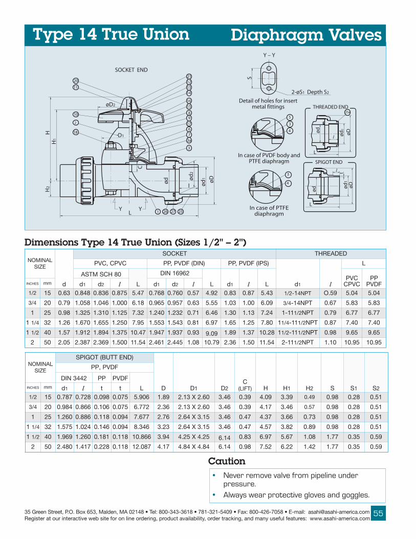
25535 Green Street, P.O. Box 653, Malden, MA 02148 • Tel: 800-343-3618 • 781-321-5409 • Fax: 800-426-7058 • E-mail: [email protected] at our interactive web site for on line ordering, product availability, order tracking, and many useful features: www.asahi-america.com
6
S
H2
H1
H 18
2-øS1 Depth S2
L 1 26 27
ød
C
ød
2
25
l ød
1
øD
3a
3
7
øD2
D1
2
10
11
SOCKET END
20 12
15
9
17
8
16
1413
21
ød
L
ød
1ø
D
L
l
ød
l
THREADED END
t
øD
ød
2
25a
SPIGOT END
In case of PTFEdiaphragm
3
4
In case of PVDF body andPTFE diaphragm
3
4
5
Detail of holes for insertmetal fittings
Y Y
Y – Y
LANIMONEZIS
d
TEKCOS DEDAERHT
CVPC,CVP )NID(FDVP,PP )SPI(FDVP,PP
d1 l
L
08HCSMTSA
L
26961NID
L d1 l LCVPCVPC
PPFDVPSEHCNI mm d1 d2 l d1 d2 l
2/1 51 36.0 848.0 638.0 578.0 74.5 867.0 067.0 75.0 29.4 38.0 78.0 34.5 -2/1 1 TPN4 95.O 40.5 40.5
4/3 02 97.0 850.1 640.1 000.1 81.6 569.0 759.0 36.0 55.5 30.1 00.1 90.6 4/3 TPN41- 76.0 38.5 38.5
1 52 89.0 523.1 013.1 521.1 23.7 042.1 232.1 17.0 64.6 03.1 31.1 42.7 11-1 2/1 TPN 97.0 77.6 77.6
1 4/1 23 62.1 076.1 556.1 052.1 59.7 355.1 345.1 18.0 79.6 56.1 52.1 08.7 1 4/1 11- 2/1 TPN 78.0 04.7 04.7
1 2/1 04 75.1 219.1 498.1 573.1 74.01 749.1 739.1 39.0 90.9 98.1 73.1 82.01 1 2/1 11- 2/1 TPN 89.0 56.9 56.9
2 05 50.2 783.2 963.2 005.1 45.11 164.2 544.2 80.1 97.01 63.2 05.1 45.11 11-2 2/1 TPN 01.1 59.01 59.01
Dimensions Type 14 True Union (Sizes 1/2" – 2")
Caution• Never remove valve from pipeline under
pressure.
• Always wear protective gloves and goggles.
Diaphragm ValvesType 14 True Union
LANIMONEZIS
)DNETTUB(TOGIPS
D D1 D2C
)TFIL( H H1 H2 S S1 S2
FDVP,PP
2443NID PP FDVP
LSEHCNI mm d1 l t t2/1 51 787.0 827.0 890.0 570.0 609.5 98.1 06.2X31.2 64.3 93.0 90.4 93.3 94.0 89.0 82.0 15.0
4/3 02 489.0 668.0 601.0 570.0 277.6 63.2 06.2X31.2 64.3 93.0 71.4 64.3 75.0 89.0 82.0 15.0
1 52 062.1 688.0 811.0 490.0 776.7 67.2 51.3X46.2 64.3 74.0 73.4 66.3 37.0 89.0 82.0 15.0
1 4/1 23 575.1 420.1 641.0 490.0 643.8 32.3 51.3X46.2 64.3 74.0 75.4 28.3 98.0 89.0 82.0 15.0
1 2/1 04 969.1 062.1 181.0 811.0 668.01 49.3 52.4X52.4 41.6 38.0 79.6 76.5 80.1 77.1 53.0 95.0
2 05 084.2 714.1 822.0 811.0 780.21 71.4 48.4X48.4 41.6 89.0 25.7 22.6 24.1 77.1 53.0 95.0

ASAHI/AMERICARev. C 03-05
56
Diaphragm ValvesType 14 True Union
All Type 14 True Union diaphragm valves shall be ofsolid thermoplastic construction for body and bonnetwith socket, threaded or butt end connectors. Thevalves shall come standard with a position indicator,travel stop and bonnet O-ring sealing arrangement.The valve shall be weir type with a square bonnet bodysealing design and bayonet connection diaphragm. AllPTFE diaphragms shall accept the installation of aPVDF gas barrier between the layers of EPDM andPTFE for aggressive chemical service. PVC conformingto ASTM D1784 Cell Classification 12454-A, CPVCconforming to ASTM D1784 Cell Classification23567-A, PP conforming to ASTM D4101 CellClassification PP0210B67272, PPG (Bonnet Only)conforming to ASTM D4101 Cell ClassificationPP0110M20A21130, and PVDF conforming to ASTMD3222 Cell Classification Type II. PVC, CPVC, PP andPVDF shall be rated to 150 psi for elastomeric andPTFE diaphragms at 70 degrees F, as manufacturedby Asahi/America, Inc.
LANIMONEZIS
CVP CVPC PP FDVP
SMGARHPAIDLLA SMGARHPAIDLLA SMGARHPAIDLLA MGARHPAIDEFTP
F0̊3F5̊01
F6̊01F0̊41
F0̊3F5̊01
F6̊01F0̊41
F1̊41F5̊71
F6̊71F5̊91
F5̊-F5̊01
F6̊01F0̊41
F1̊41F5̊71
F0̊4-F0̊41
F1̊41F5̊71
F6̊71F0̊12SEHCNI mm
2/1 51 051 031 051 511 58 04 051 511 58 051 021 594/3 02 051 031 051 511 58 04 051 511 58 051 021 59
1 52 051 031 051 511 58 04 051 511 58 051 021 591 4/1 23 051 031 051 511 58 04 051 511 58 051 021 591 2/1 04 051 031 051 511 58 04 051 511 58 051 021 59
2 05 051 031 051 511 58 04 051 511 58 051 021 59
LANIMONEZIS CV
.TW.GLF
SEHCNI mm
2/1 51 8.4 1.14/3 02 3.5 3.1
1 52 5.8 0.21 4/1 23 0.11 4.21 2/1 04 62 8.5
2 05 34 4.6
Pressure vs. Temperature PSI, WATER, NON-SHOCK Cv Values/Wt.
Note:Working temperature is different from flangedversion.
Sample Specification
TroubleshootingWhat if fluid leaks when valve is fully closed?
1. Travel stop not set correctly. Adjust it per theAsahi Operation and Maintenance manual.
2. Solids build up inside valve. Clean inside,including weir and diaphragm.
3. Diaphragm and/or weir are worn or damaged.Change the part(s).
What if valve cannot be fully opened?
1. Diaphragm is not properly engaged withcompressor. Check engagement per Operationand Maintenance manual.
What if fluid leaks to atmosphere?
1. Bonnet bolts not properly torqued. Retorqueaccording to Operation and Maintenancemanual.
2. Line pressure exceeds maximum recommendedline pressure. Check or reduce system linepressure.
3. Diaphragm has ruptured or has been chemicallyattacked. Replace diaphragm.

25735 Green Street, P.O. Box 653, Malden, MA 02148 • Tel: 800-343-3618 • 781-321-5409 • Fax: 800-426-7058 • E-mail: [email protected] at our interactive web site for on line ordering, product availability, order tracking, and many useful features: www.asahi-america.com
Type 14 Pneumatic Diaphragm
Sizes:Body Materials:
Bonnet Materials:End Connectors:
Diaphragms:Actuator Housing:
Type:Air Supply:
O-Ring End Connectors:
Specifications1/2" – 2"PVC, CPVC, PP and PVDFPPGSee Valve MaterialsSee Valve MaterialsPPGAir-to-Air; Air-to-Spring60 psi (Recommended)90 psi (Maximum
EPDM
Features• Rugged solid thermoplastic construction for
maximum corrosion resistance• Uniquely designed body and bonnet together
with diaphragms of new sealing designsby the-state-of-the-art computer aidedanalysis for superior sealing
• Weir design for excellent throttling• NAMUR pad mount for easy installation of
solenoid valves• Fully vacuum rated• Bubble-tight sealing, even in applications such
as slurries or those with suspended particles• Bonnet seals to protect internals from
corrosive environments• Adjustable travel stop to prevent diaphragm
from being over-tightened• Bayonet structure to connect compressor
and diaphragm for quick maintenance• Integrally molded bottom stand for simple yet
firm panel mounting• Indicator at the top for valve position• PVDF gas barrier, which protects EPDM
backing cushion from gas permeation, isstandardized for PVDF valves
• Low profile
Options• Solenoid valves in all NEMA ratings and
voltages• Limit switches for interface with computers
and other equipment• Positioners: 3 –15mA and 4 - 20mA inputs for
throttling applications4 – 20mA output for interface with computersand other equipment
• Manual over-ride for Air-to-Spring
2" PVDF TYPE 14AIR-TO-AIRFLANGEDDIAPHRAGMVALVE
1" PP TYPE 14AIR-TO-AIR TRUEUNIONDIAPHRAGMVALVE
2" PVC TYPE 14AIR-TO-SPRINGFLANGEDDIAPHRAGMVALVE WITH NEMA IVDOUBLE LIMITSWITCH AND NEMA IVSOLENOID VALVE

ASAHI/AMERICARev. C 03-05
58
Dimensions Type 14 Pneumatic Flanged (Sizes 1/2" – 2")
35b
L
H2
Y
D1
40
1
34a
34
H
35
n - øh
Y
t
2-øS1
3aø
d
P.C
.D.C
3
39
6
7
33
31
44
50
øD
insert metal fittings.Detail of holes for
Depth S2
S
11
35c
XXX
49
37
36
45
38
32
48
X
4641
35a
Y-Y
In case of PTFE diaphragm
3
4
In case of PVDF bodyand PTFE diaphragm
3
4
543 1421
l
H
40
34a
34
D1
1
l
7
3
3a
336
3944
35
35c
11
31
37
35b36
50
32
45
3849
1443 21
464135a
48
3
X-X
0.94aG 1 4
2-M5 Taps Depth 0.28
47
b
Face of air supply1.26
l
1.26
l
1.26
l
2-M5 Taps
Air To Shut0.94
Face of air supply
47
1.261.26
2-M5 Taps
Air To Open
G 1 4
Depth 0.28Depth 0.28
0.94
Face of air supply
a1G 4
Double Acting
G 1 4 b
D2
Diaphragm ValvesType 14 Pneumatic
NOTE:1. Operating Pressure: 60 psi – 90 psi2. Double Acting – Valve Open: Port (a) Exhaust
Port (b) SupplyValve Shut: Port (a) Supply
Port (b) Exhaust Air To Open Valve Open: Port (b) Supply
Valve Shut: Port (b) Exhaust
Air To Shut Valve Open: Port (a) ExhaustValve Shut: Port (a) Supply
3. The shape and appearance of the actualassembly may differ slightly in nominal size ascompared with this drawing
Weight/Cv
FOR ADDI-TIONAL TRUEUNION VALVEDIMENSIONS,SEE PAGE 52
LANIMONEZIS
d
051SSALCISNA
D1 D2 l L t H H2
EURTNOINU
H3 S S1 S2
.TW).SBL(
vC
C D n hA-A S-A
SEHCNI mm
2/1 51 36.0 83.2 05.3 4 26.0 06.2x31.2 21.5 93.0 52.4 34.0 23.7 94.0 23.7 89.0 82.0 15.0 08.4 21.5 8.4
4/3 02 97.0 57.2 88.3 4 26.0 06.2x31.2 21.5 93.0 88.5 15.0 04.7 75.0 04.7 89.0 82.0 15.0 11.5 87.5 3.5
1 52 89.0 21.3 52.4 4 26.0 51.3x46.2 21.5 74.0 88.5 95.0 06.7 37.0 06.7 89.0 82.0 15.0 00.6 05.6 5.8
1 4/1 23 62.1 05.3 26.4 4 26.0 51.3x46.2 21.5 74.0 83.6 36.0 67.7 98.0 67.7 89.0 82.0 15.0 05.6 00.7 0.11
1 2/1 04 75.1 88.3 00.5 4 26.0 52.4x52.4 58.6 38.0 49.6 36.0 45.11 80.1 45.11 77.1 53.0 95.0 28.21 92.41 62
2 05 50.2 57.4 00.6 4 57.0 48.4x48.4 58.6 89.0 49.7 97.0 98.11 24.1 98.11 77.1 53.0 95.0 00.31 05.41 34

25935 Green Street, P.O. Box 653, Malden, MA 02148 • Tel: 800-343-3618 • 781-321-5409 • Fax: 800-426-7058 • E-mail: [email protected] at our interactive web site for on line ordering, product availability, order tracking, and many useful features: www.asahi-america.com
Sample SpecificationAll TYPE 14 actuated diaphragm valves shall be ofsolid thermoplastic construction for body (MoldedFlanged or Tru-Union socket, threaded or butt endconnectors) and bonnet with the actuator housingof glass filled polypropylene. The actuator shallcome standard with an “at a glance” positionindicator and pad mount according to NAMUR forsolenoid mounting. Air supply shall be 60 – 90 psi.The valve body shall have a panel mount feature forsupport. Actuator to body mount shall be ofsquare design, diaphragm shall be bayonet typeconnection. Face-to-face dimensions of flangedversion shall conform to Type-G. PVC conforming toASTM D1784 Cell Classification 12454-A, CPVCconforming to ASTM D1784 Cell Classification23567-A, PP conforming to ASTM D4101 CellClassification PP0210B67272, PPG (Bonnet Only)conforming to ASTM D4101 Cell ClassificationPP0110M20A21130, and PVDF conforming toASTM D3222 Cell Classification Type II. PVC, CPVC,PP and PVDF shall be rated to 150 psi for elasto-meric and PTFE diaphragms at 70 degrees F., asmanufactured by Asahi/America, Inc.
Diaphragm ValvesType 14 Pneumatic
TroubleshootingWhat if valve does not open or close?
1. Air pressure is too low. Adjust the pressure.2. Power source of solenoid valve is off. Check the
connection.3. Solenoid wiring is disconnected. Connect.4. Solenoid voltage is low or incorrect. Check
voltage with tester and reset.
STRAP
.ON NOITPIRCSED .SCP LAIRETAM1 ydoB 1 FDVP,PP,CVPC,CVP
3 mgarhpaiD 1 srehtO,EFTP,MDPE
a3 tresnIlateMmgarhpaiD 1 403leetSsselniatS
4 *noihsuC 1 MDPE
5 **reirraBsaGFDVP 1 FDVP
6 rosserpmoC 1 FDVP
7 tnioJ 1 403leetSsselniatS
11 revoCeguaG 1 CP
41 )A(gniR-O 1 MDPE
12 wercS 1 403leetSsselniatS13 )A(metS 1 yollAreppoC
23 )B(metS 1 yollAreppoC
33 etalPhsuProsserpmoC 1 yollAreppoC
43 ydoBrednilyC 1 GPP
a43 evobAroftresnIlateM 4 yollAreppoC
53 tennoBrednilyC 1 GPP
a53 evobAroftresnIlateM 1 403leetSsselniatS
b53 evobAroftresnIlateM 8 yollAreppoC
c53 53#roftresnIdedaerhT 2 403leetSsselniatS
63 mgarhpaiDrednilyC 1 RBN
73 etalPmgarhpaiDrednilyC 2 403leetSsselniatS
83 )B(rehsaWgnirpSlacinoC 1 403leetSsselniatS
93 )A(tloB 8 403leetSsselniatS
04 )B(tloB 4 403leetSsselniatS
14 doRgnitacidnI 1 403leetSsselniatS
34 reppotS 1 403leetSsselniatS
44 )D(gniR-O 1 RBN
54 )E(gniR-O 1 RBN
64 )F(gniR-O 1 RBN
74 elppiN 1 yollAreppoC
84 )A(gnirpS 1 leetSgnirpS
94 )B(gnirpS 1 leetSgnirpS
05 )C(gnirpS 1 leetSgnirpS
Parts Type 14 Pneumatic (1/2" – 2")
* Used for PTFE diaphragm** Used for PVDF body, PTFE diaphragm
5. Air not supplied to solenoid valve.6. By-pass valve is open. Close it.7. Speed control on solenoid set incorrectly.
Adjust.
What if fluid flows even when closed?1. Operating pressure is too low (Air-to-Air only).
Adjust. Air not exhausted (Air-to-Spring only).Exhaust air.
2. Diaphragm is damaged or worn. Replace.3. Body may be damaged. Inspect and replace.4. Foreign material is caught between weir and
diaphragm. Disassemble and clean.
What if valve leaks to atmosphere?1. Bolts for body and actuator improperly
tightened. Tighten as specified in Operation andMaintenance manual.
2. True Union style: (a) Union nut(s) not tightenedproperly. Tighten; (b) O-ring between endconnector and body is damaged. Replace.
Valve cannot be opened or closed, even thoughactuator works.1. Diaphragm is damaged or its joint metal fitting
is broken. Replace part(s).

ASAHI/AMERICARev. C 03-05
60
4
4a
3
1
24
L
4
3
28
13
øD2
øD1
l (LIF
T)
21
15
t n -øhø
dP.
C.D
.C øD
6
1a
H1
3233a
10
75
9
H
121114
1716
18
1920
in case of PVDF bodyand PTFE diaphragm
in case of PTFE diaphragm
LANIMONEZIS
d
051SSALCISNA
L
t
D1 D2 l H H1SEHCNI mm C D n h CVP FDVP,PP
5 521 29.4 00.01 05.8 8 88.0 41.61 78.0 49.0 06.21 18.11 63.2 45.61 31.21
6 051 38.5 00.11 05.9 8 88.0 09.81 49.0 60.1 61.51 41.61 67.2 47.81 51.31
Dimensions Type 15 Flanged (Sizes 5" – 6")LANIMON
EZIS vC .TWSEHCNI mm
5 521 003 00.85
6 051 004 00.98
Type 15 Flanged Diaphragm
Features• Flanged face-to-face dimensions are equivalent
to those of Type G diaphragm valve• Rugged body and bonnet are of solid
thermoplastic for maximum corrosionresistance
• Bubble-tight sealing, even in applications such asslurries or suspended particles
STRAP
.ON NOITPIRCSED .SCP LAIRETAM1 ydoB 1 FDVP,PP,CVP
2 tennoB 1 FDVP,GPP,PP,CVP
3 mgarhpaiD 1 srehtO,EFTP,MDPE
a3 tresnIlateMmgarhpaiD 1 403leetSsselniatS
4 *noihsuC 1 MDPE
a4 *reirraBsaGFDVP 1 FDVP
5 rosserpmoC 1 FDVP
6 tuNrosserpmoC 1 yollAreppoC7 niProsserpmoC 1 403leetSsselniatS
8 metS 1 yollAreppoC
9 )A(eveelS 1 yollAreppoC
01 )A(gniraeBtsurhT 1muimorhCnobraChgiH
gniraeB11 )A(gniR-O 1 RBN
21 elppiNesaerG 1 yollAreppoC
31 leehWdnaH 1 PP
41 etalPemaN 1 CVP
51 paC 1 PP
61 )A(teksaGteehS 1 MDPE
71 gniRteehS 1 403leetSsselniatS
81 reppotS 1 leetSdezimorhC
02 tuN 1 403leetSsselniatS
12 revoCeguaG 1 CP
32 tuN,tloBdutS steS4 srehtO,403leetSsselniatS
42 rehsaW,tuN,tloB - 403leetSsselniatS
a1 tuNdetresnI 4403leetSsselniatS 1
yollAreppoC 2
Parts Type 15 (5" – 6")
* Used for PTFE diaphragm 1 Used for PVDF body 2 Used for PVC, PP, bodies
Sizes:Body Materials:
Bonnet Materials:Diaphragms:
Specifications5" – 6"PVC, PP and PVDFPVC, PP, PPG and PVDFEPDM and PTFEAlso available in othermaterials such as Nitrile,FKM, Butyl, Hypalon®† andNeoprene®†
††††† Trademarks of E. I. du Pont de Nemours and Company
Cv Values/Weight

26135 Green Street, P.O. Box 653, Malden, MA 02148 • Tel: 800-343-3618 • 781-321-5409 • Fax: 800-426-7058 • E-mail: [email protected] at our interactive web site for on line ordering, product availability, order tracking, and many useful features: www.asahi-america.com
Sample SpecificationAll TYPE 15 flanged diaphragm valves shall be of solidthermoplastic construction for body and bonnet withmolded flanged ends. The valves shall come standardwith a position indicator, travel stop (to prevent over-tightening) and bonnet o-ring sealing arrangement.The valve shall be weir type with a round bonnet bodysealing design and threaded stud diaphragm con-nection. All PTFE diaphragms shall accept the install-ation of a PVDF gas barrier between the layers ofEPDM and PTFE for aggressive chemical service.The face-to-face dimensions shall conform to TYPE G.PVC conforming to ASTM D1784 Cell Classification12454-A, PP conforming to ASTM D4101 CellClassification PP0210B67272, PPG (Bonnet Only)conforming to ASTM D4101 Cell ClassificationPP0110M20A21130, and PVDF conforming to ASTMD3222 Cell Classification Type II. PVC, and PP shallbe rated to 115 psi for elastomeric diaphragms at70 degrees F. PVC, PP and PVDF shall be rated to100 psi (5") and 70 psi (6") for PTFE diaphragms at70 degrees F., as manufactured by Asahi/America, Inc.
What if valve cannot be fully opened?
1. Diaphragm is not properly engaged withcompressor. Check engagement per
Operation and Maintenance manual.
What if fluid leaks to atmosphere?
1. Bonnet bolts not properly torqued. Retorqueaccording to Operation and Maintenancemanual.
2. Line pressure exceeds maximum recommended line pressure. Check or reduce system line pressure.
3. Diaphragm has ruptured or has been chemicallyattacked. Replace diaphragm.
Options• PVDF gas barrier for PVC and PP Diaphragm
Valves• 2” square operating nut
• “T” operating nuts for remote operation
• Stem extensions (single stem or two-piecestem)
• Chain operators
• Locking device for tamper-proofing
• Manual limit switches for remote positionindication by lights or for sequencing of otherequipment
Features• Weir design for excellent throttling
• Uniquely designed body and bonnet togetherwith diaphragms of new sealing designs by thestate-of-the-art computer aided analysis forsuperior sealing
• Bonnet seals to protect internals fromcorrosive environments
• Built-in travel stop to prevent diaphragm frombeing over-tightened
• Indicator at the top for valve position andprevention of over-tightening
• PVDF gas barrier, which protects EPDMbacking cushion from gas permeation, isstandardized for PVDF valves
TroubleshootingWhat if fluid leaks when valve is fully closed?
1. Travel stop not set correctly. Adjust it per theAsahi Operation and Maintenance manual.
2. Solids build up inside valve. Clean inside,including weir and diaphragm.
3. Diaphragm and/or weir are worn or damaged.Change the part(s).
Diaphragm ValvesType 15 Flanged
LANIMONEZIS
CVP PP FDVP
SREMOTSALE EFTP SREMOTSALE EFTP SREMOTSALE EFTP
SEHCNI mm F0̊3F5̊01
F6̊01F0̊41
F0̊3F5̊01
F6̊01F0̊41
F5̊-F5̊01
F6̊01F0̊41
F1̊41F5̊91
F5̊-F5̊01
F6̊01F0̊41
F1̊41F5̊91
F0̊4-F0̊41
F1̊41F5̊71
F6̊71F0̊12
F1̊12F0̊52
F0̊4-F0̊41
F1̊41F5̊71
F6̊71F0̊12
F1̊12F0̊52
5 521 511 001 001 08 511 59 07 001 08 55 511 001 58 07 001 58 07 556 051 511 07 07 55 511 09 55 07 06 04 511 59 57 55 07 06 05 04
Pressure vs. Temperature PSI, WATER, NON-SHOCK

ASAHI/AMERICARev. C 03-05
62
STRAP
.ON NOITPIRCSED .SCP LAIRETAM1 ydoB 1 FDVP,PP,CVP
2 tennoB 1 GPP,FDVP,PP,CVP
3 mgarhpaiD 1 srehtO,EFTP,MDPE
a3 tresnIlateMmgarhpaiD 1 403leetSsselniatS
4 *noihsuC 1 MDPE
a4 *reirraBsaGFDVP 1 FDVP
5 rosserpmoC 1 FDVP
7 niP 1 403leetSsselniatS8 metS 1 leetSnobraC
9 eveelS 1 norItsaC
01 )A(gniraeBtsurhT 1muimorhCnobraChgiH
gniraeB11 gniR-O 1 RBN
21 elppiNesaerG 1 yollAreppoC
31 leehWdnaH 1 PP
41 etalPemaN 1 CVP
51 paC 1 PP
61 teksaGteehS 1 MDPE
71 gniRteehS 1 403leetSsselniatS
81 reppotS 1 leetSdezimorhC
02 tuN 1 403leetSsselniatS
12 revoCeguaG 1 CP
32 tuN,tloBdutS - srehtO,403leetSsselniatS
42 rehsaW,tuN,tloB - srehtO,403leetSsselniatS
52 rehsaWgnirpSlacinoC - srehtO,403leetSsselniatS 1
62 reniLtennoBreppU teS1 srehtO,403leetSsselniatS 2
72 reniLydoB teS1 srehtO,403leetSsselniatS 2
a1 tuNdetresnI 4403leetSsselniatS 1
yollAreppoC 3
Parts Type G Flanged (Sizes 8" – 10")
* Used for PTFE diaphragm1 Used for PVDF body2 Used for PP and PVDF bodies3 Used for PVC, and PP bodies
Type G Flanged Diaphragm
Sizes:Body Materials:
Bonnet Materials:Model:
Diaphragms:
Standard Features• Rugged body and bonnet of solid thermoplastic
for maximum corrosion resistance• Weir design for excellent throttling• Bubble-tight sealing, even in applications such as
slurries or suspended particles• Bonnet seals to protect internals from corrosive
environments• Built-in travel stop to prevent diaphragm from
being over-tightened• Indicator at the top for valve position• PVDF gas barrier, which protects backing
cushion from gas permeation, is standardizedfor PVDF valves
Options• PVDF gas barrier for PVC and PP valves• 2” square nut• “T” operating nuts for remote operation• Stem extensions (single stem or two-piece
stem)• Chain operators• Locking device for tamper-proofing• Manual limit switches for remote position
indication by lights or for sequencing of otherequipment
††††† Trademarks of E. I. du Pont de Nemours and Company
Specifications8" –10"PVC, PP and PVDFPVC, PP, PPG and PVDFFlanged (ANSI)EPDM and PTFEAlso available in othermaterials such as Nitrile,FKM, Butyl, Hypalon®† andNeoprene®†
Caution
• Never remove valve from pipeline underpressure.
• Always wear protective gloves and goggles.

26335 Green Street, P.O. Box 653, Malden, MA 02148 • Tel: 800-343-3618 • 781-321-5409 • Fax: 800-426-7058 • E-mail: [email protected] at our interactive web site for on line ordering, product availability, order tracking, and many useful features: www.asahi-america.com
ød C
Lt n - øh
P.C
.D.
øD
27
1
26
2
24
13
øD1
19
21
20
øD2
Lift
H23
1a
3
5
8
H
17
15
14
16
18
125
11
1012
7
3a
9l
4
in case of PVDF bodyand PTFE diaphragm
4a
in case ofPTFE diaphragm
4
3
3
Diaphragm ValvesType G Flanged
LANIMONEZIS
d
051SSALCISNA
L
t
D1 D2 l H H1SEHCNI mm D C n h CVP FDVP,PP8 002 27.7 05.31 57.11 8 88.0 42.22 01.1 62.1 39.61 41.61 47.3 96.42 05.61
01 052 27.9 00.61 52.41 21 89.0 77.62 81.1 64.1 62.12 50.22 40.5 36.03 80.02
Dimensions Type G (Sizes 8" – 10")LANIMON
EZIS vC .TWSEHCNI mm
8 002 007 041
01 052 0001 242
Cv Values/Weight
LANIMONEZIS
CVP PP FDVP
SREMOTSALE EFTP SREMOTSALE EFTP SREMOTSALE EFTP
SEHCNI mm F0̊3F5̊01
F6̊01F0̊41
F0̊3F5̊01
F6̊01F0̊41
F5̊-F5̊01
F6̊01F0̊41
F1̊41F5̊91
F5̊-F5̊01
F6̊01F0̊41
F1̊41F5̊91
F0̊4-F5̊01
F6̊01F0̊41
F1̊41F0̊52
F0̊4-F0̊41
F1̊41F0̊52
8 002 57 06 06 54 57 55 05 06 54 54 57 55 05 06 5401 052 56 05 06 54 56 05 05 06 54 54 56 05 05 06 54
Pressure vs. Temperature PSI, WATER, NON-SHOCK

ASAHI/AMERICARev. C 03-05
64
Diaphragm ValvesType G FlangedSample SpecificationAll TYPE G flanged diaphragm valves shall be of solidthermoplastic construction for body and bonnetwith molded flanged ends. The valves shall comestandard with a position indicator, travel stop (toprevent over-tightening) and bonnet o-ring sealingarrangement. The valve shall be weir type with around bonnet body sealing design and threadedstud diaphragm connection. All PTFE diaphragmsshall accept the installation of a PVDF gas barrierbetween the layers of EPDM and PTFE foraggressive chemical service. The face-to-facedimensions shall conform to TYPE G. PVCconforming to ASTM D1784 Cell Classification12454-A, PP conforming to ASTM D4101 CellClassification PP0210B67272, PPG (Bonnet Only)conforming to ASTM D4101 Cell ClassificationPP0110M20A21130, and PVDF conforming toASTM D3222 Cell Classification Type II. PVC andPP shall be rated to 75 psi size 8"and 65 psi size10" for elastomeric diaphragms at 70 degrees F.PVC, PP and PVDF shall be rated to 60 psi for PTFEdiaphragms at 70 degrees F., as manufactured byAsahi/America, Inc.
TroubleshootingWhat if fluid leaks when valve is fully closed?
1. Travel stop not set correctly. Adjust it per theAsahi Operation and Maintenance manual.
2. Solids build up inside valve. Clean inside,including weir and diaphragm.
3. Diaphragm and/or weir are worn or damaged.Change the part(s).
What if valve cannot be fully opened?
1. Diaphragm is not properly engaged withcompressor. Check engagement per Operationand Maintenance manual.
What if fluid leaks to atmosphere?
1. Bonnet bolts not properly torqued. Retorqueaccording to Operation and Maintenancemanual.
2. Line pressure exceeds maximum recommendedline pressure. Check or reduce system linepressure.
3. Diaphragm has ruptured or has been chemicallyattacked. Replace diaphragm.
Caution• Never remove valve from pipeline under
pressure.• Always wear protective gloves and goggles.

26535 Green Street, P.O. Box 653, Malden, MA 02148 • Tel: 800-343-3618 • 781-321-5409 • Fax: 800-426-7058 • E-mail: [email protected] at our interactive web site for on line ordering, product availability, order tracking, and many useful features: www.asahi-america.com
BA
C
TO OPEN
TO CLOSE
Diaphragm Valves OptionsOperating NutsAvailable in 2" square or“T” configurations. Usedfor remote operation of avalve by a wrench.
Limit switches are usedfor remote positionindication with the use oflights or for sequencing ofother equipment.
Limit Switches
Chain OperatorsInstalled on the roundhandwheel of a valve inoverhead, out-of-reachlocations. The valve is
operated by pulling on the chain.
Locking HandlesTo prevent unauthorizedoperation, the valvehandwheel can be pad-locked in the open or closed position.
Single StemExtensionsThe valve handwheel canbe extended from thevalve for out-of-reachlocations by a singleextension. Support isrequired under thehandwheel to preventside movement.
Two-Piece Stemand HousingFor buried or submergedapplications. A PVChousing surrounds theextended stem forprotection from anaggressive environment,or to function as a box.
PATENTED WALL SUPPORT StyleDV-A
StyleDV-B

ASAHI/AMERICARev. C 03-05
66
9.25
9.06
H1
H
L
Diaphragm ValvesActuator OptionsElectrically Actuated Diaphragm
• Brushless, capacitor-run motors (115V/60 Hz)• Integral thermal overload protection with auto-
reset• Permanently lubricated gear train• Combination NEMA 4X, 7 and 9 enclosure with
thermally bonded powder coating/304 ss trim• ISO bolt circle• Two 1/2" NPT conduit ports prevent inter-
ference between control and power signals• Declutchable manual override• Highly visible position indicator• 3-layer rotary switch for dry contact indication
Standard Features (Sizes 1/2" – 4")
Options• Heater and thermostat (to -40º F)• Milliamp positioner: 4–20mA or 0–10 Vdc
input signal• 4–20mA output position transmitter• Extra limit switches for lights or sequencing
other equipment• Feedback potentiometer
Series 92 Electric Actuators
Cycle Times Weight Dimensions
ACTUATOR DEPTH: 9.25"
*Duty Cycle: 25%
NOTE: CONSULT FACTORY FOR SIZES GREATER THAN 4"FOR TRUE UNION "L" DIMENSIONS SEE PAGE 51.
AC Wiring (For 115 Vac only)
}
MSW-1
BLA
CK
1
WH
ITE
2WH
ITE
CLOSE
OPEN
BLU
E
3
BLU
E
4
JUMPERS
BLA
CK
(CO
MM
ON
)
WHITE
BLUE
RS-1
RS-2BLUE
AC VOLTS}
5 76 8 9
BLU
E
WH
ITE
ORANGEBROWN
BLUEPINK
RS-3OPEN
CLOSE
10 11
SW-2
OPE
NIN
DIC
ATI
ON
CLO
SED
IND
ICA
TIO
N
NOTE TO WIRING DIAGRAM:
1. EACH ACTUATOR MUST BEPOWERED THROUGH ITS OWNINDIVIDUAL SWITCH CON-TACTS TO AVOID CROSS FEED.
2. MOTOR HAS A THERMALPROTECTOR AS SHOWN BY MIN DIAGRAM.
4. IF 115 VAC MODELS AREPLC DRIVEN, OUTPUT CON-TACTS OF PLC SHOULD BERATED AT A MINIMUM OF 1.5TIMES REQUIRED INPUTVOLTAGE OF ACTUATOR.
LANIMONEZIS .TW
).SBL(SEHCNI mm
2/1 51 05.61
4/3 02 08.61
1 52 04.71
1 2/1 04 02.12
2 05 00.32
2 2/1 56 33.92
3 08 46.23
4 001 08.04
LANIMONEZIS EMIT
).CES(SEHCNI mm
2/1 51 091
4/3 02 012
1 52 012
1 2/1 04 012
2 05 012
2 2/1 56 012
3 08 072
4 001 072
LANIMONEZIS
H H1 LSEHCNI mm
2/1 51 57.1 55.3 52.4
4/3 02 49.1 16.3 88.5
1 52 31.2 77.3 88.5
1 2/1 04 05.2 05.6 49.6
2 05 00.3 20.7 49.7
2 2/1 56 05.3 25.9 48.9
3 08 57.3 52.01 83.01
4 001 05.4 00.11 49.21

26735 Green Street, P.O. Box 653, Malden, MA 02148 • Tel: 800-343-3618 • 781-321-5409 • Fax: 800-426-7058 • E-mail: [email protected] at our interactive web site for on line ordering, product availability, order tracking, and many useful features: www.asahi-america.com
Diaphragm ValvesActuator OptionsPneumatically Actuated Diaphragm
• Air-to-Spring diaphragm actuator
• Choice of failsafe action can be either Spring-to-Close or Spring-to-Open
• Corrosion resistant, coated, die-cast aluminumbody
• Diaphragm of Nylon-reinforced Neoprene
• Actuator working pressure: 60 psi
• 1/4 NPT air connection
• Position indicator
• Travel stop
Standard Features (Sizes 1/2" – 4")
Options• Solenoids in all NEMA ratings and voltages
• 4–20mA output for interface with computersand other equipment
• Travel stops for limiting valve lift
• Limit switches for interface with computers andother equipment
• Positioners: 3-15mA and 4-20mA inputs forthrottling applications
• Manual override
LANIMONEZIS ROTAUTCA
SEHCNI mm
2/1 51 52P
4/3 02 52P
1 52 52P
1 2/1 04 52P
2 05 05P
2 2/1 56 05P
3 08 011P
4 001 011P
LANIMONEZIS .TW
).SBL(SEHCNI mm
2/1 51 5.51
4/3 02 0.71
1 52 0.81
1 2/1 04 5.12
2 05 0.03
2 2/1 56 5.43
3 08 0.28
4 001 0.78
Actuator Sizing Weight
LANIMONEZIS
W A L H H1 H2SEHCNI mm
2/1 51 5.6 9.7 52.4 94. 53.2 4.31
4/3 02 5.6 9.7 88.5 75. 34.2 4.31
1 52 5.6 9.7 88.5 37. 96.2 4.31
1 2/1 04 5.6 9.7 49.6 80.1 72.4 4.31
2 05 6.6 5.01 49.7 24.1 48.4 6.61
2 2/1 56 6.6 5.01 48.9 04.2 18.5 6.61
3 08 6.7 2.51 83.01 84.2 82.6 5.62
4 001 6.7 2.51 49.21 70.3 68.7 5.62
Dimensions (Sizes 1/2" – 4")
WWA A
H2
H1H1
H2
HH
LL
INSTRUMENTAIR
SUPPLYAIR
NOITACIFICEPS TINU 52P 05P 011P
aerAmgarhpaiDevitceffE ni( 2 ) 00.52 00.05 0.011
)ekortsorezta(emuloVriA ni( 3 ) 17.6 53.12 7.24
)ekortsllufta(emuloVriA ni( 3 ) 60.82 83.69 8.292
)isp06(emiTekortSlacipyT ).ces( 3 4 8
Specifications

ASAHI/AMERICA68Rev. C 03-05
SpecificationsSizes: 3/4" – 8"
Models: Flanged (ANSI) Connection OnlyLever and Weight Option
Bodies: HI-PVC, PP and PVDFSeats: EPDM, FKM, PTFE
Seal: EPDM, FKM, PTFE
Options:
Parts List (Sizes 3/4" – 8")Standard Features (Sizes 3/4" – 8")
Parts List (Lever and Weight)
• Minimum flow resistance - Low pressure drop• Horizontal or vertical installation• All sizes rated for full vacuum service• Minimum back pressure to seat disc tightly• Top access cover facilitates maintenance
without body removal from pipeline• All thermoplastic body• All PVC parts made of high impact PVC• PVC and PP Valves come with EPDM seals
(Part #'s 5j, 5k, 6 and 7) as standard• PVDF Valves, Part #'s 5j and 7 of PTFE and 6 of
PVDF bonded EPDM• 3/4" PP Valves supplied with Ring 1a
• External lever and weight to assist disc inclosing faster
• External spring to assist disc in closing faster• PTFE or FKM Seat and O-Rings
Swing Check Valve
New Higher
Pressure Rating
STRAP
.ON NOITPIRCSED .SCP LAIRETAM
1 ydoB 1 FDVP,PP,CVP
2 tennoB 1 FDVP,PP,CVP
3 tfahS 1 FDVP,PP,CVP
4 tloB 1 FDVP,PP,CVP
a5 csiD 1 FDVP,PP,CVP
b5 redloHtaeS 1 FDVP,PP,CVP
c5 )A(tloB - FDVP,PP,CVP
d5 mrA 1 FDVP,PP,CVP
e5 rehsaW 1 FDVP,PP,CVP
f5 )A(tuN 1 FDVP,PP,CVP
g5 niP 1 FDVP,PP,CVP
h5 )B(tloB 1 FDVP,PP,CVP
i5 )B(tuN 1 FDVP,PP,CVP
j5 taeS 1 srehtO,EFTP,MDPE
k5 )A(gniR-O 1 srehtO,EFTP,MDPE
6 )A(teksaG 1 EFTP
7 )B(teksaG 1 srehtO,EFTP,MDPE
8 )B(gniR-O teS srehtO,EFTP,MDPE
9 rehsaW,tuN,tloB teS 403leetSsselniatS
a1 gniR 1 403leetSsselniatS
STRAP
.ON NOITPIRCSED .SCP LAIRETAM
1 gnittiF 1 FDVP,PP,CVP
2 tuN 1 FDVP,PP,CVP
3 tfahS 1 613leetSsselniatS
31 thgieWretnuoC 1 CVP
5 recapS 1 FDVP,PP,CVP
6 gniR-O 1 MKF,MDPE
7 tloBpaCxeH teS 613leetSsselniatS
8 wercSteS teS 613leetSsselniatS

35 Green Street, P.O. Box 653, Malden, MA 02148 • Tel: 800-343-3618 • 781-321-5409 • Fax: 800-426-7058 • E-mail: [email protected] at our interactive web site for on line ordering, product availability, order tracking, and many useful features: www.asahi-america.com
69
Swing Check Valves
Dimensions (Sizes 3/4" – 8")
STANDARD PVDF MODEL
1"
5a5j
L
5i 5b 5h5k t 5j5b5c
1.42
H1
2
CP.
C.D
.ød
1
8
øD
H1
3
X
9
5g5f5e5aL
t
5d
X
ød
182
øD1
8"
n- øh
P.C
.D. øDC
374
X-X
4/3 "
(The opposite side)
n- øh
X X
øD1
1a
1"
5a5j
L
5i 5b 5h5k t 5j5b5c
1.42
H
2
CP.
C.D
.ød
1
6
øD
H
3
X
9
5g5f5e5aL
t
5d
X
ød
162
øD1
8"
n- øh
P.C
.D. øDC
374
X-X
4/3 "
(The opposite side)
n- øh
X X
øD1
1a
LANIMONEZIS
d
051SSALCISNA
D1 L
t
1H HSEHCNI mm C D h n CVP FDVP,PP
4/3 02 97.0 57.2 88.3 26.0 4 93.3 15.5 95.0 95.0 34.3 45.3
1 52 89.0 21.3 52.4 26.0 4 21.5 03.6 36.0 36.0 16.4 27.4
1 2/1 04 75.1 88.3 00.5 26.0 4 17.5 90.7 17.0 17.0 13.5 34.5
2 05 79.1 57.4 00.6 57.0 4 90.7 78.7 97.0 38.0 43.6 64.6
2 2/1 56 65.2 05.5 00.7 57.0 4 78.7 54.9 78.0 19.0 05.6 16.6
3 08 51.3 00.6 05.7 57.0 4 70.8 42.01 78.0 89.0 16.6 37.6
4 001 49.3 05.7 00.9 57.0 8 34.01 18.11 49.0 20.1 72.8 93.8
5 521 29.4 05.8 00.01 88.0 8 99.21 87.31 49.0 60.1 56.9 67.9
6 051 19.5 05.9 00.11 88.0 8 75.41 57.51 89.0 60.1 20.11 41.11
8 002 78.7 57.11 05.31 88.0 8 37.61 96.91 81.1 43.1 11.31 32.31
PVC&PP(Elastomeric Seals)
PVDF

ASAHI/AMERICA70Rev. C 03-05
A
H
L
7
2 5 8 3
6
4
1
Rod
Spring
Spring
Hex Cap Bolt& Washer
AttachmentLever
Swing Check Valve
Dimensions (Lever &Weight/External Spring)
Sample Specification
LANIMONEZIS A
H
SEHCNI mm PP,CVP FDVP
4/3 02 0.4 34.3 45.3
1 52 5.4 27.4 27.4
1 2/1 04 0.5 34.5 34.5
2 05 5.5 64.6 64.6
2 2/1 56 0.6 16.6 16.6
3 08 5.6 37.6 37.6
4 001 0.8 93.8 93.8
5 521 0.01 67.9 67.9
6 051 5.01 41.11 41.11
8 002 0.21 32.31 32.31
SPRING ASSIST(OPTION)PVC, PP, PVDF
All Swing Check valves shall be of solid thermoplastic construction, having no metal that comes incontact with media. (Except when Lever & Weight or SS spring option is installed) Valves shallincorporate a single disc design suitable for either horizontal or vertical installations. Valves shall be oftop entry bonnet design for maintenance purposes. PVC shall conform to ASTM D1784 CellClassification 12454-A, PP conforming to ASTM D4101 Cell Classification PP0210B67272 and PVDFconforming to ASTM D3222 Cell Classification Type II. Valves shall be rated to 150 psi sizes 3/4” thru3”, 100 psi sizes 4” thru 6”, 75 psi size 8” for PVC or PP with EPDM or FKM seals, 90 psi sizes 3/4”thru 2-1/2”, 75 psi sizes 3” & 4”, 60 psi size 5” and 45 psi sizes 6” & 8” for PVC with Teflon® seals, 90psi sizes 3/4” thru 2-1/2”, 75 psi sizes 3” & 4”, 60 psi size 5” and 45 psi sizes 6” & 8” for PP or PVDFwith Teflon® seals all at 70 degrees F, as manufactured by Asahi/America, Inc.
LEVER AND WEIGHT(OPTION)PVC, PP, PVDF

35 Green Street, P.O. Box 653, Malden, MA 02148 • Tel: 800-343-3618 • 781-321-5409 • Fax: 800-426-7058 • E-mail: [email protected] at our interactive web site for on line ordering, product availability, order tracking, and many useful features: www.asahi-america.com
71
Swing Check ValvesPressure vs. Temperature (PSI, WATER, NON-SHOCK)
WeightLANIMON
EZIS .SBLSEHCNI mm
4/3 02 02.2
1 52 04.4
1 2/1 04 16.6
2 05 41.01
2 2/1 56 33.41
3 08 35.61
4 001 54.62
5 521 00.44
6 051 25.95
8 002 95.29
Minimum Back Pressure toClose Valve (PSI)
Cv ValuesLANIMON
EZIS vCSEHCNI mm
4/3 02 41
1 52 42
1 2/1 04 18
2 05 041
2 2/1 56 052
3 08 082
4 001 015
5 521 057
6 051 0011
8 002 0091
Pressure vs. Temperature (PSI, WATER, NON-SHOCK)
TroubleshootingWhat if valve leaks through the seat?
1. Sediment build-up around disc and seat. Clean disc and seat.
2. Disc or seat broken or damaged. Replace disc or seat.
3. Insufficient back pressure. Check the pressure.What if valve leaks between bonnet and body?
1. Bolts not tightened properly. Tighten firmly per specified torque.
2. Seal chemically attacked or worn. Replace seal.3. Exceeds maximum allowable pressure rating
LANIMONEZIS
CVP PP FDVP
EFTP EFTP EFTP
Fº03Fº021
Fº5-Fº041
Fº141Fº571
Fº03-Fº041
Fº141Fº571
Fº671Fº012
SEHCNI mm
4/3 02 09 09 57 09 57 06
1 52 09 09 57 09 57 06
1 2/1 04 09 09 57 09 57 06
2 05 09 09 57 09 57 06
2 2/1 56 09 09 57 09 57 06
3 08 57 57 06 57 06 54
4 001 57 57 06 57 06 54
5 521 06 06 54 06 54 04
6 051 54 54 03 54 04 03
8 002 54 54 03 54 04 03
LANIMONEZIS TAES
SEHCNI mm SREMOTSALE EFTP
4/3 02 8.2 0.5
1 52 0.5 5.8
2/11 04 0.5 5.8
2 05 0.5 5.8
2/12 56 0.5 5.8
3 08 7.5 5.8
4 001 7.5 2.9
5 521 7.5 2.9
6 051 4.6 0.01
8 002 4.6 0.01
LANIMONEZIS
CVP PP FDVP
SREMOTSALE SREMOTSALE SREMOTSALE
Fº03Fº08
Fº18Fº58
Fº68Fº021
Fº5-Fº58
Fº68Fº59
Fº69Fº041
Fº141Fº571
Fº03-Fº041
Fº141Fº571
Fº671Fº012
SEHCNI mm
4/3 02 051 531 001 051 051 001 58 09 57 06
1 52 051 531 001 051 051 001 58 09 57 06
1 2/1 04 051 531 001 051 051 001 58 09 57 06
2 05 051 531 001 051 051 001 58 09 57 06
2 2/1 56 051 531 001 051 051 001 58 09 57 06
3 08 051 531 001 051 051 001 58 57 06 54
4 001 001 001 57 001 09 57 55 57 06 54
5 521 001 001 57 001 09 57 55 06 54 04
6 051 001 001 57 001 09 57 55 54 04 03
8 002 57 57 55 57 56 04 03 54 04 03

ASAHI/AMERICARev. C 03-05
72
FLANGED END
øD ød
n-øh t3 8 4 59 1 2 10
L
L
3
øDød
1
l
THREADED END
L
ød
1ø
Død
2
SOCKET END
l
øD
1ø
d1
L
3SPIGOT END
t
3a
P.C
.D.
C øD
1
3
l
LANIMONEZIS
DEGNALF DEDAERHT
d D1
TEKCOS )DNETTUB(TOGIPS
SSALCISNA051
L t d1 l L
CVPC,CVP FDVP,PP )NID( FDVP,PP )SPI( FDVP,PP
FDVP,PP
L
26961NID
L d1 l L
2443NID PP FDVP
LSEHCNI mm D C n h d1 d2 l d1 d2 l d1 l t t2/1 51 05.3 83.2 4 26.0 21.5 74.0 2/1 TPN41- 95.0 93.3 95.0 98.1 848.0 638.0 886.0 34.3 867.0 067.0 75.0 91.3 38.0 78.0 13.3 787.0 827.0 890.0 570.0 00.4
4/3 02 88.3 57.2 4 26.0 01.6 55.0 4/3 TPN41- 76.0 60.4 97.0 63.2 850.1 640.1 917.0 68.3 569.0 759.0 36.0 07.3 30.1 00.1 34.4 489.0 668.0 601.0 570.0 53.4
1 52 52.4 21.3 4 26.0 05.6 55.0 11-1 2/1 TPN 97.0 54.4 89.0 67.2 523.1 013.1 578.0 73.4 042.1 232.1 17.0 31.4 03.1 31.1 53.4 062.1 668.0 811.0 490.0 57.4
1 4/1 03 - - - - - - 1 4/1 11- 2/1 TPN 78.0 00.5 22.1 87.3 076.1 556.1 839.0 29.4 - - - - - - - - - - - -
1 2/1 04 00.5 88.3 4 26.0 65.7 36.0 1 2/1 11- 2/1 TPN 89.0 49.5 75.1 87.3 219.1 498.1 490.1 49.5 749.1 739.1 39.0 26.5 98.1 73.1 75.5 969.1 062.1 181.0 811.0 57.5
2 05 00.6 57.4 4 57.0 34.8 36.0 11-2 2/1 TPN 01.1 79.6 10.2 71.4 783.2 963.2 651.1 77.6 164.2 544.2 80.1 96.6 63.2 05.1 94.6 084.2 714.1 822.0 811.0 05.6
Parts List – True Union (Sizes 1/2" – 2")
SpecificationsSizes: True Union : 1 /2" – 2"
Single Union: 3" – 4"Models: Socket, Threaded, Flanged (ANSI),
Butt EndBodies: PVC, CPVC, PP and PVDF
Seats: EPDM, FKM, PTFESeals: EPDM, FKM, PTFE
Option: Foot Valve
True Union Ball Check Valve
Options:
Standard Features (Sizes 1/2" – 2")• Uniseat/seal of EPDM or FKM• Ball is the only moving part. It unseats to permit
flow in one direction but seals against seat toprevent backflow.
• May be used vertically or horizontally• Minimum shut-off of 5 psi• All sizes rated for full vacuum service• Solid thermoplastic ball
• PTFE coated FKM uniseat/seal• Spring-loaded ball to assist ball in seating faster
Dimensions (Sizes 1/2" – 2")
* Used for flanged end** Used for CPVC body, threaded end; 1/2" – 1"
STRAP
.ON NOITPIRCSED .SCP LAIRETAM
1 ydoB 1 FDVP,PP,CVPC,CVP
2 llaB 1 FDVP,PP,CVPC,CVP
3 rotcennoCdnE 2 FDVP,PP,CVPC,CVP
4 tuNnoinU 2 FDVP,PP,CVPC,CVP
5 )A(gniRpotS 1 FDVP,PP,CVPC,CVP
8 *)B(gniRpotS 1 FDVP
9 taeS 1 EFTP,MKF,MDPE
01 gniR-O 1 EFTP,MKF,MDPE
a3 **gniR 1 403leetSsselniatS
Sizes 1/2" - 4" PVC/EPDM/FKM Models are available with NSF-61 Certification

35 Green Street, P.O. Box 653, Malden, MA 02148 • Tel: 800-343-3618 • 781-321-5409 • Fax: 800-426-7058 • E-mail: [email protected] at our interactive web site for on line ordering, product availability, order tracking, and many useful features: www.asahi-america.com
73
ød
2
4
Cø
DP.
C.D
. ød
øD
1
n- øh
3
t1
8
ød C
P.C
.D. øD
øD
1ø
d1
2
FLANGED END
L
9 5 1 7 6
n- øht2 THREADED END
ød
2
ød
ød ød
1
ød
1
øD
1
ød
SOCKET END
43 9
L
5 1 2 4a 3 4
ød
1
59
L
1 2 4a
ød
1
ødød
2
L
l943 5 1
SPIGOT END
øD
1
t
l l l l
* Used for flanged end
Parts List – Single Union (Sizes 3" – 4")
LANIMONEZIS
d D1
DEGNALF TEKCOS DEDAERHT )DNETTUB(TOGIPS
ssalCISNA051
L t1 t2
CVPC,CVP )NID(FDVP,PP )SPI(FDVP,PP
d1 l L
FDVP,PP
04HCSMTSA
L
26961NID
L d1 l L
2443NID PP FDVP
LSEHCNI mm D C n h d1 d2 l d1 d2 l d1 l t t
3 08 70.3 89.5 05.7 00.6 4 57.0 02.21 17.0 78.0 615.3 294.3 578.1 75.9 215.3 894.3 04.1 64.8 084.3 478.1 55.9 TPN8-3 83.1 47.8 345.3 694.1 323.0 961.0 76.11
4 001 49.3 72.8 00.9 05.7 8 57.0 36.51 17.0 78.0 815.4 194.4 000.2 02.21 392.4 872.4 36.1 64.11 084.4 252.2 06.21 TPN8-4 77.1 90.21 133.4 257.1 493.0 902.0 39.31
Ball Check
SINGLE UNIONSOCKET
SINGLE UNIONTHREADED
SINGLE UNIONFLANGED
FOOTVALVES
Single Union
Dimensions (Sizes 3" – 4")
All ball check valves and foot valves shall be of solidthermoplastic construction, and shall be designed withan elastomeric uniseat/seal for tight shut-off underpressure. Sizes 1/2" through 2" shall be of TrueUnion design, while 3" & 4" shall be Single Uniondesign. The same seal shall function as both the ballseat and the union seal. PVC shall conform to ASTMD1784 Cell Classification 12454-A, CPVC shallconform to ASTM D1784 Cell Classification 23567-A,PP shall conform to ASTM D4101 Cell ClassificationPP0210B67272 and PVDF shall conform to ASTMD3222 Cell Classification Type II. Ball Check valvesand foot valves sizes 1/2"– 2" shall be rated 150 psiat 70 degrees F, 3" and 4" rated 100 psi at 70degrees F, as manufactured by Asahi/America, Inc.
Sample Specification – (BALL CHECK VALVES)True Union, Single Union,and Foot ValveWeight (POUNDS) Cv Values
LANIMONEZIS vC
SEHCNI mm
2/1 51 5.6
4/3 02 71
1 52 52
1 2/1 04 68
2 05 031
3 08 082
4 001 005
LANIMONEZIS TEKCOS DEGNALF
SEHCNI mm
2/1 51 22.0 66.0
4/3 02 44.0 01.1
1 52 66.0 45.1
1 2/1 04 45.1 02.2
2 05 02.2 13.3
3 08 71.6 29.9
4 001 99.41 52.42
STRAP
.ON NOITPIRCSED .SCP LAIRETAM1 ydoB 1 FDVP,PP,CVPC,CVP
2 llaB 1 FDVP,PP,CVPC,CVP
3 rotcennoCdnE 1 FDVP,PP,CVPC,CVP
4 tuNnoinU 1 FDVP,PP,CVPC,CVP
5 )A(gniRpotS 1 FDVP,PP,CVPC,CVP
6 egnalF FDVP,CVPC,CVP
7 butS FDVP,CVPC,CVP
8 *)B(gniRpotS 1 FDVP9 taeS 1 EFTP,MKF,MDPE

ASAHI/AMERICARev. C 03-05
74
3
ø1
ø1
l
THREADED END
L
SOCKET END
3
FLANGED ENDø
DP.
C.D
.Cød
n-øh34 59 1 2 10
L
11
ø2
t
11
øD2
FLANGED END
3 4 9 5
L
21 7t
6
ødP.
C.D
. øD
L
l
øD1
øhn-
L
l 1
ød1
1
Parts List Foot Valve (Sizes 1/2" – 2")
Foot Valve OptionBall CheckParts List Foot Valve (Sizes 3" – 4")
LANIMONEZIS
CVP CVPC PP FDVP
F°03F°021
F°03F°021
F°121F°041
F°141F°571
F°671F°591
F°5-F°58
F°68F°041
F°141F°571
F°03-F°041
F°141F°571
F°671F°591
F°691F°012SEHCNI mm
2/1 - 2 05-51 051 051 021 09 06 051 09 06 051 521 011 09
4-3 001-08 001 001 09 06 54 57 06 54 001 09 06 54
Pressure vs. Temperature – BALL CHECK AND FOOT VALVES (PSI, WATER, NON-SHOCK)
Foot Valve Wt. (LBS) Dimensions (1/2"– 4")
* Used for flanged end * Used for flanged end
LANIMONEZIS TEKCOS DEGNALF
SEHCNI mm
2/1 51 22.0 66.0
4/3 02 44.0 88.0
1 52 66.0 23.1
1 2/1 04 45.1 13.3
2 05 02.2 13.3
3 08 17.7 20.11
4 001 34.51 41.32
Caution
• Never remove valve from pipeline underpressure.
• Always wear protective gloves and goggles.
SIZES 1/2" – 2" SIZES 3" – 4"
STRAP
.ON NOITPIRCSED .SCP LAIRETAM1 ydoB 1 CVP
2 llaB 1 CVP
3 rotcennoCdnE 1 CVP
4 tuNnoinU 1 CVP
5 )A(gniRpotS 1 CVP
8 *)B(gniRpotS 1 FDVP
9 taeS 1 EFTP,MKF,MDPE
01 gniR-O 2 EFTP,MKF,MDPE11 neercS 1 CVP
STRAP
.ON NOITPIRCSED .SCP LAIRETAM1 ydoB 1 CVP
2 llaB 1 CVP
3 rotcennoCdnE 1 CVP
4 tuNnoinU 1 CVP
5 )A(gniRpotS 1 CVP
6 *egnalF 1 CVP
7 *butS 1 CVP
9 taeS 1 EFTP,MKF,MDPE11 neercS 1 CVP
LANIMONEZIS
2D
.COS D'RHT .GLF
SEHCNI mm L L L2/1 51 63.2 37.4 96.4 04.5
4/3 02 67.2 23.5 25.5 04.6
1 52 87.3 42.6 23.6 09.6
1 2/1 04 42.5 33.8 33.8 05.8
2 05 42.5 79.8 71.9 05.01
3 08 08.11 06.21 08.11 06.41
4 001 52.81 52.81 52.81 52.02

35 Green Street, P.O. Box 653, Malden, MA 02148 • Tel: 800-343-3618 • 781-321-5409 • Fax: 800-426-7058 • E-mail: [email protected] at our interactive web site for on line ordering, product availability, order tracking, and many useful features: www.asahi-america.com
275
Gate Valve
Specifications1-----1/2" – 14"High Impact PVCFlanged (ANSI)Threaded (Type S, 2")1. "P" Type: PP, 1-1/2" – 14"2. "S" Type: CPVC-SBR-lined‡
(Non-Rising Stem) 1-1/2 " – 8"EPDM, FKM(Optional)
‡ ‡ ‡ ‡ ‡ SBR: Styrene Butadiene Rubber
Sizes:Sizes:Sizes:Sizes:Sizes:Body:Body:Body:Body:Body:
Models:Models:Models:Models:Models:
Types /Sizes:Types /Sizes:Types /Sizes:Types /Sizes:Types /Sizes:
Seals:Seals:Seals:Seals:Seals:
Standard Features• Straight-through flow with minimal pressure
drop
• Unique sliding cylindrical plug design provideslarger seating area than conventional gatevalves
• Made of durable, corrosion resistant plastic
• No metal to media contact anywhere in valve
• Clean-out (drain) plug in bottom area of valvebody in models with polypropylene gate
• Rated for full vacuum service
• Light weight for easier and economicalinstallation
• Positive bubble-tight shut-off, both PP andCPVC-SBR lined gates
• Visual position indicator
Features (ON CPVC-SBR-LINED PLUG MODELS)
• Shallow seat recess in bottom of valve bodymakes valve self-cleaning and eliminatessediment build-up
• Soft seal for easy shut-off
2" SQUAREOPERATING
NUT
Type P Parts (Sizes 1-1/2" – 6")
Options• 2” square operating nut
• Stem extensions• Locking handles• Electric actuation, up to 3”• FKM seals
Caution• Never remove valve from pipeline under
pressure.• Always wear protective gloves and goggles.
* Stem holder
STRAP
.ON NOITPIRCSED .SCP LAIRETAM1 ydoB 1 CVP
2 )gulP(etaG 1 PP
3 metS 1 CVP
4 )A(tennoB 1 CVP
5 *)B(tennoB 1 CVP
6 gniraeBtsurhT teS1 PP
7 rehsaW,tuN,tloB - 403leetSsselniatS8 leehWdnaH 1 PP
9 revoCgnitacidnI 1 CP
01 gniRgnitacidnI 1 CVP
11 niPediuG 1 403leetSsselniatS
21 redloHniPediuG 1 CVP
31 teksaG 1 MDPE
41 )A(gniR-O 1 MDPE
51 rehsaW 1 CVP
61 tuN 1 403leetSsselniatS
71 )B(gniR-O 1 srehtO,MDPE
81 )C(gniR-O 2 srehtO,MDPE
32 teksaGteehS 1 srehtO,MDPE
42 gulP 1 CVP
Sizes 1 1/2" - 14" PVC/PP/EPDM/FKM Models available with NSF-61 Certification

ASAHI/AMERICARev. C 03-05
76
16
10
13
6
5
12
15
7
3
12
4
L
ød
t
øD
CP.
C.D
.
øD1
5", 6"
ød ød
1
14H
2
H
l(L
IFT)
n - øh
8
9
11
17
18
H1
øA
23
24
Gate ValvesType PSizes 1-1/2" – 6"
LANIMONEZIS
d d1
051SSALCISNA
L t D1 A l H1 H2 HSEHCNI mm D C n h1 2/1 04 75.1 - 00.5 88.3 4 26.0 05.6 78.0 27.4 27.4 39.1 12.4 02.5 14.9
2 05 79.1 - 00.6 57.4 4 57.0 10.7 19.0 21.5 21.5 63.2 82.5 53.5 36.01
2 2/1 56 65.2 - 00.7 05.5 4 57.0 84.7 49.0 01.6 01.6 59.2 89.5 19.5 98.11
3 08 59.2 - 05.7 00.6 4 57.0 99.7 89.0 96.6 96.6 53.3 96.6 01.6 97.21
4 001 49.3 - 00.9 05.7 8 57.0 20.9 60.1 86.7 86.7 33.4 51.8 24.6 75.41
5 521 29.4 33.4 00.01 05.8 8 88.0 42.01 60.1 52.9 52.9 16.4 49.8 90.7 30.61
6 051 19.5 21.5 00.11 05.9 8 88.0 15.01 60.1 36.01 36.01 34.5 53.01 71.7 25.71
LANIMONEZIS F°03
F°021SEHCNI mm
1 8-2/1 002-04 051
01 052 011
41-21 053-003 57
Dimensions (Sizes 1-1/2" – 6")
Pressure vs. Temp.(PSI, WATER, NON-SHOCK)
Troubleshooting
What if there are leaks between bonnet and body?
1. Bolts are not tightened properly. Tightendiagonally and evenly.
2. O-ring between body and bonnet damaged orworn. Change O-ring.
What if fluid still flows when fully closed?
1. Body or plug is worn or damaged. Replace.
2. Seat is worn or damaged. Replace.3. Foreign material caught at the bottom of
body. Needs cleaning.What if handle does not engage with stem?
1. Stem damaged or broken. Change stem.
2. Engaging part of stem and/or plug damaged or broken. Need to replace stem and/or plug.
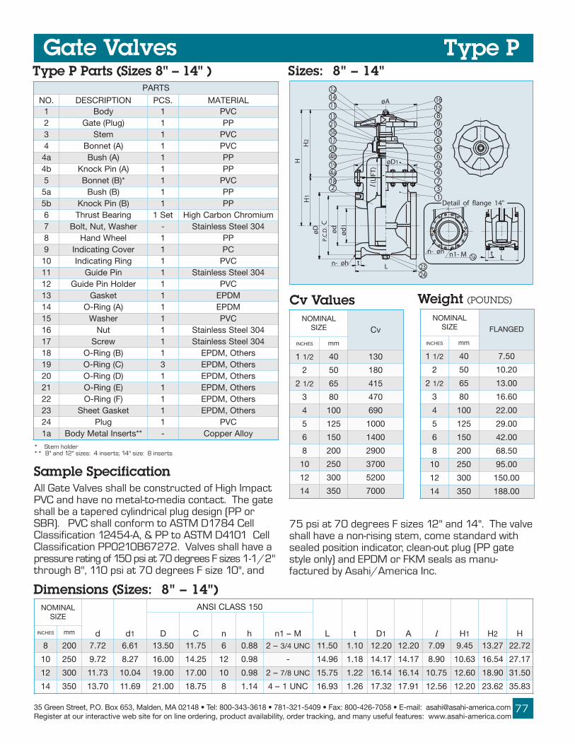
35 Green Street, P.O. Box 653, Malden, MA 02148 • Tel: 800-343-3618 • 781-321-5409 • Fax: 800-426-7058 • E-mail: [email protected] at our interactive web site for on line ordering, product availability, order tracking, and many useful features: www.asahi-america.com
277
L
øD1
øA
tn- øh
ød
ød
1Cø
DP.
C.D
.
H1
H2
H
121411
1615
105
21
17
13
20
19 22
184
31
2
(LIF
T)l
4a
4b5a
5b
6
7
89
2423
n- øh n1- M Lt1a
Detail of flange 14"
Gate ValvesSizes: 8" – 14"Type P Parts (Sizes 8" – 14" )
* Stem holder** 8" and 12" sizes: 4 inserts; 14" size: 8 inserts
Type P
LANIMONEZIS vC
SEHCNI mm
1 2/1 04 031
2 05 081
2 2/1 56 514
3 08 074
4 001 096
5 521 0001
6 051 0041
8 002 0092
01 052 0073
21 003 0025
41 053 0007
LANIMONEZIS DEGNALF
SEHCNI mm
1 2/1 04 05.7
2 05 02.01
2 2/1 56 00.31
3 08 06.61
4 001 00.22
5 521 00.92
6 051 00.24
8 002 05.86
01 052 00.59
21 003 00.051
41 053 00.881
Cv Values Weight (POUNDS)
LANIMONEZIS
d d1
051SSALCISNA
L t D1 A l H1 H2 HD C n h M–1nSEHCNI mm
8 002 27.7 16.6 05.31 57.11 6 88.0 –2 CNU4/3 05.11 01.1 02.21 02.21 90.7 54.9 72.31 27.22
01 052 27.9 72.8 00.61 52.41 21 89.0 - 69.41 81.1 71.41 71.41 09.8 36.01 45.61 71.72
21 003 37.11 40.01 00.91 00.71 01 89.0 –2 CNU8/7 57.51 22.1 41.61 41.61 57.01 06.21 09.81 05.13
41 053 07.31 96.11 00.12 57.81 8 41.1 CNU1–4 39.61 62.1 23.71 19.71 65.21 02.21 26.32 38.53
Dimensions (Sizes: 8" – 14")
All Gate Valves shall be constructed of High ImpactPVC and have no metal-to-media contact. The gateshall be a tapered cylindrical plug design (PP orSBR). PVC shall conform to ASTM D1784 CellClassification 12454-A, & PP to ASTM D4101 CellClassification PP0210B67272. Valves shall have apressure rating of 150 psi at 70 degrees F sizes 1-1/2"through 8", 110 psi at 70 degrees F size 10", and
Sample Specification
75 psi at 70 degrees F sizes 12" and 14". The valveshall have a non-rising stem, come standard withsealed position indicator, clean-out plug (PP gatestyle only) and EPDM or FKM seals as manu-factured by Asahi/America Inc.
STRAP
.ON NOITPIRCSED .SCP LAIRETAM1 ydoB 1 CVP2 )gulP(etaG 1 PP3 metS 1 CVP4 )A(tennoB 1 CVPa4 )A(hsuB 1 PPb4 )A(niPkconK 1 PP5 *)B(tennoB 1 CVPa5 )B(hsuB 1 PPb5 )B(niPkconK 1 PP6 gniraeBtsurhT teS1 muimorhCnobraChgiH7 rehsaW,tuN,tloB - 403leetSsselniatS8 leehWdnaH 1 PP9 revoCgnitacidnI 1 CP01 gniRgnitacidnI 1 CVP11 niPediuG 1 403leetSsselniatS21 redloHniPediuG 1 CVP31 teksaG 1 MDPE41 )A(gniR-O 1 MDPE51 rehsaW 1 CVP61 tuN 1 403leetSsselniatS71 wercS 1 403leetSsselniatS81 )B(gniR-O 1 srehtO,MDPE91 )C(gniR-O 3 srehtO,MDPE02 )D(gniR-O 1 srehtO,MDPE12 )E(gniR-O 1 srehtO,MDPE22 )F(gniR-O 1 srehtO,MDPE32 teksaGteehS 1 srehtO,MDPE42 gulP 1 CVPa1 **stresnIlateMydoB - yollAreppoC

ASAHI/AMERICARev. C 03-05
78
6
H1
1
H2
H
3
4
7
L
tn - øh
C
l1
ød
LIFT
øD22b
øD
P.C
.D.
2c
8
5
9
29
22
23
28
H3
FLANGED END
26
21
24
25
27
Ll
ød
2
ød
1
THREADED END
ød
ød
1
5", 6"
øA
STRAP
.ON NOITPIRCSED .SCP LAIRETAM1 ydoB 1 CVP
a2 taeS 1 RBS
c2 )A(etaG 1 CVPC
3 metS 1 CVP
4 )A(tennoB 1 CVP
5 )B(tennoB 1 CVP
6 gniRtsurhT teS1 PP
7 rehsaW,tuN,tloB - 403leetSsselniatS8 )B(gniR-O 1 MDPE
9 )C(gniR-O 2 MDPE
12 gnikcaP 1 MDPE
22 leehWdnaH 1 PP
32 revoCgnitacidnI 1 CP
42 gniRgnitacidnI 1 CVP
52 niPediuG 1 403leetSsselniatS
62 redloHniPediuG 1 CVP
72 )G(gniR-O 1 MDPE
82 rehsaW 1 CVP
92 tuNxoB 1 403leetSsselniatS
Gate ValvesType S
Type S Parts – "Soft Seal" (Sizes 2" – 6" )LANIMON
EZIS
d d1
DEGNALF
051SSALCISNASEHCNI mm D C n h L t A
2 05 79.1 79.1 00.6 57.4 4 57.0 00.7 19.0 21.5
2 2/1 56 65.2 - 00.7 05.5 4 57.0 05.7 49.0 01.6
3 08 59.2 - 05.7 00.6 4 57.0 00.8 00.1 96.6
4 001 49.3 - 00.9 05.7 8 57.0 00.9 60.1 86.7
5 521 29.4 33.4 00.01 05.8 8 88.0 52.01 60.1 52.9
6 051 19.5 21.5 00.11 05.9 8 88.0 05.01 60.1 36.01
LANIMONEZIS
DEDAERHT
D2 l1 H H1 H2 H3d2 l LSEHCNI mm
2 05 2/111-2 TPN 01.1 21.5 21.5 50.2 36.01 82.2 82.5 53.5
2 2/1 56 - - - 01.6 46.2 98.11 86.2 89.5 19.5
3 08 - - - 96.6 30.3 97.21 30.3 96.6 01.6
4 001 - - - 86.7 20.4 75.41 05.3 51.8 24.6
5 521 - - - 52.9 14.4 30.61 05.3 49.8 90.7
6 051 - - - 36.01 02.5 25.71 20.4 53.01 71.7
Type S Dimensions (Sizes 2" – 6" )
Type S Dimensions
Sizes 2" – 6"

35 Green Street, P.O. Box 653, Malden, MA 02148 • Tel: 800-343-3618 • 781-321-5409 • Fax: 800-426-7058 • E-mail: [email protected] at our interactive web site for on line ordering, product availability, order tracking, and many useful features: www.asahi-america.com
279
7
H1
2b
2h
2c
2e
H2
1
3
Ln- øht
l1 L
IFT
ød
1
ød
øD
P.C
.D.
C
2g
2f
1a
8
n -M
H
11
4
6
24
H3 5
28
22
23
29
øA
øD2
14
17
16
15
10
9
2627
25
Gate Valves
STRAP
.ON NOITPIRCSED .SCP LAIRETAM1 ydoB 1 CVP
a1 stresnIlateMydoB 4 yollAreppoC
a2 taeS 1 RBS
c2 )A(etaG 1 CVPC
e2 )B(etaG 1 PP
f2 )A(stresnIlateMetaG 4 yollAreppoC
g2 )A(tloB 4 403leetSsselniatS
h2 )A(gniR-O 1 MDPE
3 metS 1 CVP
4 )A(tennoB 1 CVP
5 )B(tennoB 1 CVP
6 gniRtsurhT teS1 muimorhCnobraChgiHgniraeB
7 rehsaW,tuN,tloB steS21 403leetSsselniatS
8 )B(gniR-O 1 MDPE
9 )C(gniR-O 3 MDPE
01 )A(gnihsuB 1 PP
11 )B(gnihsuB 1 PP
41 )E(gniR-O 1 MDPE
51 )F(gniR-O 1 MDPE
61 )D(gniR-O 1 MDPE
71 )A(wercSteS 1 403leetSsselniatS
22 leehWdnaH 1 PP
32 revoCgnitacidnI 1 CP
42 gniRgnitacidnI 1 CVP
52 niPediuG 1 403leetSsselniatS
62 redloHniPediuG 1 CVP
72 )G(gniR-O 1 MDPE
82 rehsaW 1 CVP
92 tuNxoB 1 403leetSsselniatS
LANIMONEZIS
d d1
051SSALCISNA
AD C n h n1 MSEHCNI mm
8 002 27.7 16.6 05.31 57.11 6 88.0 2 W 4/3 02.21
LANIMONEZIS
L t D2 l1 H H1 H2 H3SEHCNI mm
8 002 05.11 01.1 02.21 98.6 27.22 36.5 54.9 72.31
TroubleshootingWhat if fluid still flows when fully closed?
1. Body or plug is worn or damaged. Replace.
2. Seat is worn or damaged. Replace.
3. Foreign material caught at the bottom ofbody. Needs cleaning.
What if there are leaks between bonnet and body?
1. Bolts are not tightened properly. Tightendiagonally and evenly.
2. O-ring between body and bonnet damaged orworn. Change O-ring.
Type S Parts – "Soft Seal" (Size 8" )
Type S Dimensions (Size 8" )
Type S Dimensions
What if there is difficulty in rotating handle?
1. Foreign material build-up on plug. Needs tobe cleaned.
2. Disc damaged or swollen. Check chemicalcompatability.
3. Visual indicator not set properly
What if handle does not engage with stem?
1. Stem damaged or broken. Change stem.
2. Engaging part of stem and/or plug damagedor broken. Need to replace stem and/or plug.
Type S
Troubleshooting

ASAHI/AMERICARev. C 03-05
80
Gate Valves
Chain OperatorChain OperatorChain OperatorChain OperatorChain OperatorFor overhead, out-of-reach locations. The valve isoperated by pulling on the chain installed on roundhand-wheel.
A
B
C
A
B
Options
Two-piece Stem HousingFor submerged or buried applications. PVC housingprotects stem extensions from aggressiveenvironments. Stems are available in carbon steelwith baked powder epoxy coating, stainless steel(303 and 316 etc.)
Valve handle can be extended away from the valvefor out-of-reach locations. Stems come in CarbonSteel with baked powder epoxy coating, stainlesssteel (303 and 316 etc.)Option: Wall-support (Patented) and Collar
Locking MechanismLocking MechanismLocking MechanismLocking MechanismLocking MechanismPrevents unauthorized cycling of a valve. Designedto be secured with a padlock. Two designs.
Special O-RingsSpecial O-RingsSpecial O-RingsSpecial O-RingsSpecial O-RingsFKM O-rings for corrosive applications.
Remote Operating NutsRemote Operating NutsRemote Operating NutsRemote Operating NutsRemote Operating Nuts2" square or “T” configurations on valve stem,replacing the hand-wheel. Used for remoteoperation of a valve by an extended wrench.Material: 6061 Aluminum, anodized finish
2" SQUAREOPERATINGNUT
ORIGINALGATEVALVE
CHAIN
WALL SUPPORT(OPTIONAL)
COLLAR
Single Stem Extensions (Non-supported)
STYLE GT-A STYLE GT-B
CHAINOPERATOR

35 Green Street, P.O. Box 653, Malden, MA 02148 • Tel: 800-343-3618 • 781-321-5409 • Fax: 800-426-7058 • E-mail: [email protected] at our interactive web site for on line ordering, product availability, order tracking, and many useful features: www.asahi-america.com
281
9.25
9.06
H1
H
L
Engineering Data
Series 92 Electric Actuators
• Brushless, capacitor-run motors• Integral thermal overload protection with auto-
reset• Permanently lubricated gear train• Combination NEMA 4X, 7 and 9 enclosure with
thermally bonded powder coating/304 ss trim• ISO bolt circle• Two 1/2" NPT conduit ports prevent inter-
ference between control and power signals• Declutchable manual override• Highly visible position indicator• 3-Layer rotary switch for dry contact indication
Standard Features (Sizes 1-1/2" – 3")
Options• Extra limit switches• Feedback potentiometer• Heater and thermostat (to -40º F)• Milliamp positioner: 4–20mA or 0–10 Vdc
input signal• 4–20mA output position transmitter
AC Wiring (For 115 Vac only)
Electric Actuator Specifications
Series 92: Motor Type – Reversing, singlephase
Model – S92 for sizes1-1/2" – 3"Torque – 400 in.- lbs.Voltage – 120 Vac, 50/60 HzMax Ambient Temp. – 150˚ FSwitches – Two single pole, double
throw (15 Amp rating)
SERIES 92 ONTYPE P GATEVALVE
NOTE TO WIRING DIAGRAM:1. IF 120 VAC MODEL IS PLCDRIVEN, OUTPUT CONTACTSOF PLC SHOULD BE RATED ATA MINIMUM OF 1.5 TIMESREQUIRED INPUT VOLTAGE OFACTUATOR.2. EACH ACTUATOR MUST BEPOWERED THROUGH ITS OWNINDIVIDUAL SWITCH CON-TACTS TO AVOID CROSS FEED.3. MOTOR HAS A THERMALPROTECTOR AS SHOWN BY MIN DIAGRAM.
Dimensions
}
MSW-1
BLA
CK
1
WH
ITE
2WH
ITE
CLOSE
OPEN
BLU
E
3
BLU
E
4
JUMPERS
BLA
CK
(CO
MM
ON
)
WHITE
BLUE
RS-1
RS-2BLUE
AC VOLTS}
5 76 8 9
BLU
E
WH
ITE
ORANGEBROWN
BLUEPINK
RS-3OPEN
CLOSE
10 11
SW-2
OPE
NIN
DIC
ATI
ON
CLO
SED
IND
ICA
TIO
N
ROTAUTCALEDOM EGATLOV ELCYCYTUD PMA
WARD THGIEW
29S CAV021 %52 05. .sbl01
LANIMONEZIS
H H1 LSEHCNI mm
1 2/1 04 05.2 00.9 05.6
2 05 00.3 64.01 10.7
3 08 57.3 60.41 99.7

ASAHI/AMERICARev. C 03-05
82
Standard Features• EPDM – durometer A, hardness 65 - 68• PTFE or PVDF-bonded EPDM for maximum
corrosion resistance• Perfect sealing at low bolt tightening torque
ratings, longer gasket life• Ideal for plastic piping systems, as well as metal
or plastic-lined metal systems• Working temperature:
1) EPDM: - 40 – 195º F2) PTFE-bonded: - 40 – 250º F3) PVDF-bonded: - 40 – 250º F
• Approx. a 1/3 bolt tightening torque ratings ascompared with flat or envelope type gasket.
• Thickness of bonded materials PTFE: All Sizes: 0.016" (0.4mm)
PVDF: Sizes 1/2" - 2": 0.016" (0.4mm) PVDF: Sizes 3" - 10": 0.020" (0.5mm)• PTFE-bonded gasket excellent for most
corrosive chemicals.• PVDF-bonded gasket is ideal for the following:
1] Semi-conductor industry because of its purity2] Aggressive chemicals (strong acids,
bases, halogens, etc.)3] Media that generates any volatile gas (PVDF
gas permeation is only 1/50 of PTFE)• Both the PTFE and PVDF-bonded gaskets
employ a proprietary laminating process forbonding to EPDM, providing the greaterelasticity required for lower sealing torques.
Low Torque AV Gaskets
Materials/Sizes:
Low Torque AV Gaskets
Sample SpecificationAll AV Gaskets shall be of low torque, full face to ANSIB16.5 dimensions and shall have two concentric,convex, molded rings between center hole and bolt holecircle in EPDM, PTFE-bonded EPDM or PVDF-bondedEPDM, as manufactured by Asahi/America, Inc.
RecommendedBolt Torque*
1) EPDM:1/2" - 12"2) PTFE-bonded EPDM:1/2" - 12"3) PVDF-bonded EPDM:1/2" - 10"(Except 1-1/4" and 2-1/2")
LANIMONEZIS EFTP
FDVP MDPESEHCNI mm
2/1 51 471 751
4/3 02 471 751
1 52 471 751
1 4/1 03 191 561
1 2/1 04 712 471
2 05 712 471
2 2/1 56 403 712
3 08 403 712
4 001 403 712
5 521 843 062
6 051 843 062
8 002 534 403
01 052 534 403
21 003 225 534
Dimensions(Sizes 1/2" – 12")
LANIMONEZIS
D1 D2 D3 D4 D5 h nSEHCNI mm
2/1 51 7.0 0.1 6.1 4.2 4.3 6.0 4
4/3 02 9.0 3.1 9.1 8.2 8.3 6.0 4
1 52 2.1 5.1 1.2 1.3 2.4 6.0 4
1 4/1 03 5.1 0.2 6.2 5.3 5.4 6.0 4
1 2/1 04 7.1 1.2 7.2 9.3 9.4 6.0 4
2 05 1.2 7.2 3.3 7.4 9.5 8.0 4
2 2/1 56 7.2 4.3 0.4 5.5 9.6 8.0 4
3 08 2.3 9.3 4.4 0.6 4.7 8.0 4
4 001 0.4 7.4 4.5 5.7 9.8 8.0 8
5 521 0.5 7.5 5.6 5.8 9.9 9.0 8
6 051 9.5 6.6 5.7 5.9 9.01 9.0 8
8 002 8.7 5.8 7.9 8.11 4.31 9.0 8
01 052 8.9 6.01 1.21 3.41 9.51 0.1 21
21 003 1.11 8.21 9.31 0.71 9.81 0.1 21
n-øh
PVDF or PTFE øD3øD2
øD1øD4
øD5
n-øh
øD3øD2
øD1øD4
øD5
5/64”
5/64”EPDM
PVDF or PTFE-Bonded Gasket
EPDM Gasket
* Expressed in INCH-POUNDS
Specifications

35 Green Street, P.O. Box 653, Malden, MA 02148 • Tel: 800-343-3618 • 781-321-5409 • Fax: 800-426-7058 • E-mail: [email protected] at our interactive web site for on line ordering, product availability, order tracking, and many useful features: www.asahi-america.com
83
SpecificationsPVC: 1/2", 3/4", 1", 2", 3", 4"CPVC: 1" and 2"PVC, CPVC (1" and 2")PVC, CPVC (1" and 2")Flanged ANSIEPDMStainless Steel 304 with ETFECoatingPVC: 30 – 120º FCPVC: 30 – 160º F(1" & 2" only)
Options• Seals in Neoprene®, FKM*, etc.• Also available in flanged DIN (Metric), etc.
Standard Features (Sizes 1/2" – 4")
Constant Flow Valves
Sizes:
Body:Bonnet:Models:
Seals:Springs:
Temperature:
• Body and bonnet are of solid PVC or CPVC• All wetted parts are of thermoplastic and
elastomeric materials for superior corrosionresistance
• A preset constant flow rate is maintained byautomatically regulating orifice opening area,responding to changes of pressure differentialsacross the valve – see "Principles of Operation "on the following page
• Vertical or horizontal installations• Flow rate accuracy: plus or minus 6 % of full
scale flow rate (water at ambient temperature)• Flow rate rangeability: 20 : 1 maximum• Hand wheel permits ON/OFF opening and closing• Hand wheel serves as a mechanism by which the
flow rate setting may be adjusted withoutshutting down the pipeline
• Springs of Stainless Steel 304 with ETFEcoating tested for long cycle life
• Prescribed flow setting is clearly visible on theindicator at the top
Sample SpecificationAll constant flow valves shall be of solidthermoplastic-flanged construction, and all wettedparts shall be of non-metallic materials. Size 1/2"and 3/4" shall be of inline design, while 1" - 4" shallbe a Y type design. PVC shall conform to ASTMD1784 Cell Classification 12454-A, CPVC shallconform to ASTM Cell Classification 23567-A.Spring construction shall be 304 ss with ETFEcoating. All constant flow valves shall have acalibrated flow dial and position indicator. Valveaccuracy shall be +/- 6% of full scale. Constant flowvalve sizes 1/2"-3" shall have a maximum upstreampressure range of 150 psi at 120 degree F. andSize 4" 70 psi at 120 degree F as manufactured byAsahi/America, Inc.
FLOW FLOW
TYPE SIZESA 1", 2" 3"B 1/2", 3/4", 1", 2", 3",
D 3", 4"
CHARACTERISTICSFluid flows through the valveFlow rate setting range is large (small to large flow rate)Lines with large pressure differ re eam)High flow rate
TYPE A (1" – 3") TYPE B (1/2" –TYPE C (1/2" – 4")TYPE D (3" –
P1 P2 P2 P1
*Consult Factory

ASAHI/AMERICARev. C 03-05
84
HH
1
n- øh9
18
1
7
16
6
5
13
2
L
W t
P.C
.D.ø
d C
øD
22
8
3
21
17
24
19
øD2
10
11
20
14
12
4
23
15
2
H
STRAP
.ON NOITPIRCSED .SCP LAIRETAM1 ydoB 1 CVP
2 tennoB 1 CVP
3 rednilyC 1 CVP
4 notsiP 1 CVP
5 gulP 1 CVP
6 ecifirO 1 CVP
7 taeS 1 MDPE
8 tuNpaC 1 CVP9 paC 1 CVP
01 esaBgnirpS 1 CVP
11 gniRpotS 1 FDVP
21 eveelS 1 yollAreppoC
31 )A(gnirpS 1 *403leetSsselniatS
41 )B(gnirpS 1 *403leetSsselniatS
51 tuN 1 CVP
61 )A(gniR-O 1 MDPE
71 )B(gniR-O 1 MDPE
81 )C(gniR-O 1 MDPE
91 )D(gniR-O 1 MDPE
02 yeK 2 PP
12 gniRtsurhT 1 PP
22 esaBeldnaH 1 CVP
32 revoCeldnaH 1 CVP
42 wercS 4 403leetSsselniatS
Constant FlowValvesParts (Sizes 1/2" – 3/4")
* With ETFE coating
Dimensions (Sizes 1/2" – 3/4")
Principles of Operation 1. When the upstream fluid pressure, P1, isintroduced at the flow control orifice, it exerts aresponding pressure on the upper surface of theflange on the piston type valve plug.
2. Likewise, the downstream pressure, P2,exerts a corresponding pressure to the lowersurface of the valve plug flange.
3. Thus, when a differential exists between thefluid upstream and downstream of the orifice, thecorresponding differential pressure acting on thesurfaces of the flange moves the valve plug pistoneither downward against the force of the springcartridge or upward by the force of the spring,depending upon the direction of the force inducedby the existing differential pressure.
4. This upward or downward movement ofthe valve plug piston causes the flow orfice to bewidened or narrowed accordingly, thus the flow rateof the fluid passing across the orifice is automaticallyadjusted. For example, if the differential pressure,(P1 – P2) created between the upstream anddownstream sides of the orifice increases,the valve plug piston moves downward to narrowthe area of the orifice opening and automaticallyadjusts to the preset flow rate value. The reverse isalso true when the differential pressure decreases,piston moves upward increasing the orifice openingarea and allowing the fluid flow rate to increase tothe preset value.
NOTE: THE PISTON FOR TYPE B, C AND D DOES NOT HAVEINLET FLUID PASSAGE. THE PRESSURE DIF-FERENTIAL, (P1 –P2), EXERTS DIRECTLY ON THE PLUG SURFACE.
LANIMONEZIS
W D2 H H1 HSEHCNI mm
2/1 51 32.3X32.3 60.4 67.7 80.5 10.2
4/3 02 32.3X32.3 60.4 67.7 00.5 90.2
1/2" – 3/4" Model
LANIMONEZIS
d
051SSALCISNA
L tSEHCNI mm D c n h2/1 51 36.0 05.3 83.2 4 26.0 03.6 74.0
4/3 02 97.0 88.3 57.2 4 26.0 03.6 15.0

35 Green Street, P.O. Box 653, Malden, MA 02148 • Tel: 800-343-3618 • 781-321-5409 • Fax: 800-426-7058 • E-mail: [email protected] at our interactive web site for on line ordering, product availability, order tracking, and many useful features: www.asahi-america.com
85
n- øh
tl1 l2
ød
P.C
.D.øD C
L
(TYPE B,C)
FLOW(TYPE A)
98
57
6
B
43
A
2018
1719 øE
11
1101522116
22
1314
1223
H50˚
STRAP
.ON NOITPIRCSED .SCP LAIRETAM1 ydoB 1 CVP
2 tennoB 1 CVP
3 rednilyC 1 CVP
4 notsiP 1 CVP
5 gulP 1 CVP
6 esaBgnirpS 1 CVP
7 gniRpotS 1 FDVP
8 ecifirO 1 CVP9 taeS 1 MDPE
01 )A(gniR-O 1 MDPE
11 )B(gniR-O 1 MDPE
21 )C(gniR-O 1 MDPE
31 eveelS 1 yollAreppoC
41 paC 1 CVP
51 yeK 2 CVP
61 gniRtsurhT 1 PP
71 )A(gnirpS 1 *403leetSsselniatS
81 )B(gnirpS 1 *403leetSsselniatS
91 )A(rehsaW 1 CVP
02 )B(rehsaW 1 CVP
12 leehWdnaH 1 PP
22 wercS 4 yollAreppoC
32 rotacidnItfiL 1 CVP
Preset Flow Rates(AND WORKING DIFFERENTIAL PRESSURE)
LANIMONEZIS
EPYT ETARWOLF YTILIBAEGNAR
GNIKROWLAITNEREFFID
ERUSSERP
SEHCNI mm .NIM/.LAG ISP
2/1 51B 25.3–671.0 1:02 22.41–58.2
C 25.3–53.0 1:01 54.82–72.4
4/3 02B 82.5–62.0 1:02 22.41–58.2
C 82.5–35.0 1:01 54.82–72.4
1 52
A 18.8–02.2 1:4 22.41–58.2
B 18.8–144.0 1:02 22.41–58.2
C 18.8–188.0 1:01 54.82–72.4
2 05
A 22.53–18.8 1:4 22.41–58.2
B 22.53–67.1 1:02 22.41–58.2
C 22.53–25.3 1:01 54.82–72.4
3 08
A 70.88–20.22 1:4 22.41–58.4
B 70.88–304.4 1:02 22.41–58.2
C 70.88–18.8 1:01 54.82–72.4
D 01.231–40.66 1:2 33.12–72.4
4 001C 02.462–30.44 1:6 54.82–72.4
D 02.46201.231 1:2 33.12–58.2Parts (Sizes 1" – 4")
* With ETFE coating
Constant FlowValves 1" – 4" Model
LANIMONEZIS DEGNALF
SEHCNI mm
2/1 51 13.3
4/3 02 13.3
1 52 13.3
2 05 20.11
3 08 47.81
4 001 83.63
Weight (POUNDS)

ASAHI/AMERICARev. C 03-05
86
Tips On Constant Flow Valve• Keep constant flow rate without power or labor.
• To operate, simply rotate handle clockwise tobring indicator to the designated position.
• Rotate handle clockwise to decrease the flowand counter-clockwise to increase.
• To fully close the valve, rotate handle clockwiseto bring the indicator to “0” (zero) position.
• To properly set a new flow rate, rotate handlecounter-clockwise till the indicator goes beyondthe intended new rate. Then, reverse (rotateclockwise) to the new rate.
• Indicator must be positioned at “0” (zero) ofthe gauge, if bonnet is to be disassembled.
• The valves are ideal for:
1. Any constant media supply
2. Well-balanced fluid supply in parallel pipingsystems
3. Simultaneous and even fluid supply tomulti-pipelines, multi- tanks, large and small pools
4. Cooling towers and scrubbers etc.
Constant FlowValves
Caution• Constant Flow valves are intended for “Clean
Fluid” services. Should the possibility of foreignmatters exist in the media, a sediment strainerof 60 mesh is to be installed in the upstream ofthe valve. For added protection, avoid installingvalves with bonnet facing downward, regardlessof vertical or horizontal installation.
• For the utmost functional accuracy, thefollowing conditions apply:
1. Media specific gravity: Sizes 1/2" - 3" up to1.4, Sizes 4" up to 1.1
2. Media viscosity: maximum 30 cp
3. Working pressures are grouped into 4 thatcorrelate to working temperatures per theformat below.
• For size 4", maximum upstream workingpressure is 70 psi.
• Make sure of the “Flow Direction”, clearlymarked on the valve body, before installation.
• Note that flow direction of Type A is differentfrom that of Type B, C and D.
• The valve can be installed either vertically orhorizontally as long as fluid always fills the valvefluid passage.
• Never operate the valves when indicator is outof the gauge range.
• Never attempt to disassemble indicator unit atthe top (preset by the factory).
• Never remove valve from pipeline under pressure.
• Always wear protective gloves and goggles.
Dimensions (Sizes 1" – 4")LANIMON
EZIS
d
051SSALCISNA
I1 I2 L t A B H E eergeDSEHCNI mm D C n h1 52 89.0 52.4 21.3 4 26.0 75.1 27.4 03.6 55.0 17.01 19.7 85.8 19.5 05
2 05 50.2 00.6 57.4 4 57.0 71.2 98.6 60.9 97.0 53.51 71.21 90.21 72.8 05
3 08 70.3 05.7 00.6 4 57.0 67.2 72.8 20.11 78.0 60.91 42.51 48.41 72.8 05
LANIMONEZIS
d D
051SSALCISNA
1I 2I L t A B H E eergeDSEHCNI mm C n h4 001 49.3 66.8 05.7 8 57.0 53.3 04.21 57.51 78.0 35.42 20.91 65.71 48.9 05

35 Green Street, P.O. Box 653, Malden, MA 02148 • Tel: 800-343-3618 • 781-321-5409 • Fax: 800-426-7058 • E-mail: [email protected] at our interactive web site for on line ordering, product availability, order tracking, and many useful features: www.asahi-america.com
87
Constant FlowValves
TroubleshootingWhat if fluid flows even when valve is fully closed?
1. Either seat or plug is damaged. Replace bodyor cylinder.
2. Foreign material caught between plug andorifice. Clean seat and plug.
What if valve cannot be closed?
1. Foreign material trapped or built up betweenplug and orifice. Disassemble and clean.
What if fluid leaks outside?
1. O-ring is chemically attacked or damaged.Replace O-ring.
What if flow is extraordinarily small?
1. Insufficient differential pressure. Adjustdifferential pressure.
2. Foreign material caught between plug andorifice. Clean.
What if flow rate exceeds the preset range?
1. Differential pressure exceeded the range.Adjust differential pressure.
2. Damaged or worn plug and/or orifice. Consultfactory.
3. Foreign material caught between plug and orifice.
Ordering InformationService Conditions1. Media:___________ Conc:___________%
2. Specific Gravity________ Viscosity________
3. Line Temperature:Max.______ (° F)
Line Temperature:Min.______ (° F)
4. Flow Req'd: Max_________ (gpm)
Min_________ (gpm)
5. Max Line Pressure:Upstream_________ (psi)
Downstream_______ (psi)
6. Min Line Pressure:Upstream_________ (psi)
Downstream_______ (psi)
Valve Specifications1. Line Size:_______________
2. Type:__________________
3. Temp. Range:___________
4. Pres. Range:____________
5. Seal Material:___________
6. Connection:_____________
LAIRETAMYDOB CVP CVPCERUTAREPMET F°58-53 F°501-68 F°021-601 F°041-121 F°061-141
MAERTSPUERUSSERP
EGNAR
ISP53-0
ISP07-53
ISP011-07
ISP051-011
Available Upstream Pressure Range(Size 1/2" - 4", Type-A,B,C,D)
Max. Allowable Upstream Pressure• PVC 1/2" - 3"; 0 - 150 PSI
• PVC 4"; 0 - 70 PSI
• CPVC 1"&2"; 0 - 150 PSI

ASAHI/AMERICARev. C 03-05
88
Standard Features• True Union design facilitates installation or
repair without expanding the pipeline
• Large filtration capacities and low pressure drops
• Transparent PVC strainer body permits easyevaluation of filter screen’s condition
• Complete thermoplastic construction
• Pressure rating: 1/2" – 2", 150 psi; 3" and 4",85 psi
• Sizes 1/2" – 2" supplied with two sets of endconnectors (socket and threaded)
Specifications
Sediment Strainers
Sizes:Models:
Body:Screens:
Seals:
Sediment Strainers
Sample SpecificationAll True Union Sediment Strainers, Sizes 1/2"– 4",shall be of true union design and shall beconstructed of transparent PVC. All O-rings shall beEPDM or FKM. Screens shall be 20, 30 and 40mesh PVC or 20, 40 and 60 mesh 316 SS. Filtermaintenance is achieved without removing strainerfrom the pipeline. PVC shall conform to ASTMD1784 Cell Classification 12454-A. Valves shall berated to 150 psi sizes 1/2" thru 2" and 85 psisizes 3" and 4" at 70 degrees F, as manufacturedby Asahi/America, Inc.
Tips on Sediment Strainers
• Clean screen regularly.
• Union nut of screening section can beremoved for quick and easy maintenance (noneed to remove body from pipeline).
• Sediment strainers protect pipeline’simportant and costly components, such aspumps and meters, by removing suspendedparticles and impurities.
• Filtering section must face downward wheninstalled.
• You must identify flow direction, shown bymolded “Arrow” on the body, beforeinstallation.
Options• FKM seals for corrosive media
• Stainless Steel 316 screens available in 20, 40and 60 mesh
• Inline cleaning (clean out valve)
1/2” – 4”Socket, Threaded, Flanged (ANSI)PVCStandard: 20 mesh PVCOptional: PVC - 30 and 40 meshStainless Steel - 20, 40 and 60 meshEPDM, FKMSizes 1/2" - 4" PVC/EPDM/FKMModels available with NSF-61Certification
** Used for flanged end
Parts (Sizes 1/2" – 4")STRAP
.ON NOITPIRCSED .SCP LAIRETAM1 ydoB 1 CVP
2 neercSretliF 1 613leetSsselniatS,CVP
3 troppuSneercS 1 CVP
4 rotcennoCdnE 2 CVP
5 tuNnoinU 3 CVP
6 gniRgniniateR 1 CVP
7 gniRtilpS 1 CVP
8 )A(gniR-O 1 srehtO,MKF,MDPE9 )B(gniR-O 2 srehtO,MKF,MDPE
01 gniRpotS 2 **FDVP

35 Green Street, P.O. Box 653, Malden, MA 02148 • Tel: 800-343-3618 • 781-321-5409 • Fax: 800-426-7058 • E-mail: [email protected] at our interactive web site for on line ordering, product availability, order tracking, and many useful features: www.asahi-america.com
289
FLANGED END
P.C
.D.
C
øD
n- øh
H2
H1
L
ød
øD1
5 9 4101
2
6
3
87
lød
2
øD
1
ød
1
L
4
THREADED END
SOCKET END
L
l ød
1
øD
1
4
t
Sediment Strainers
Dimensions (Sizes 1/2" – 4")
LANIMONEZIS vC
SEHCNI mm
2/1 51 2.5
4/3 02 5.7
1 52 41
1 2/1 04 43
2 05 05
3 08 011
4 001 561
LANIMONEZIS TEKCOS
DEDAERHTDEGNALF
SEHCNI mm
2/1 51 66.0 01.1
4/3 02 23.1 02.2
1 52 67.1 13.3
1 2/1 04 14.4 15.5
2 05 15.5 28.8
3 08 34.51 47.81
4 001 87.04 91.54
Weight (POUNDS) Cv Values)HCNIRAENILREPSELOH(HSEM 02 03 04
)HCNI(EZISELCITRAPMUMIXAM 330. 320. 110.)µ03-01(EZISELCITRAPNORCIM 048 595 024
Filter Screen Sizes*
• Never remove strainer from pipeline underpressure.
• Always wear protective gloves and goggles.
Caution* For 60 mesh consult factory
LANIMONEZIS
DEGNALF TEKCOS DEDAERHT
d D1 H1 H2
051SSALCISNA
L t
04SSALCMTSA
L d1 l LSEHCNI mm D C n h d1 d2 l2/1 51 05.3 83.2 4 26.0 11.8 74.0 848.0 638.0 886.0 24.6 2/1 TPN41- 95.0 83.6 95.0 98.1 47.3 91.34/3 02 88.3 57.2 4 26.0 00.01 55.0 850.1 640.1 917.0 67.7 4/3 TPN41- 76.0 78.7 97.0 63.2 94.4 47.3
1 52 52.4 21.3 4 26.0 20.11 55.0 523.1 013.1 578.0 09.8 11-1 2/1 TPN 97.0 89.8 89.0 67.2 21.5 33.41 4/1 03 - - - - - - 076.1 556.1 839.0 82.11 1 4/1 11- 2/1 TPN 78.0 16.11 75.1 87.3 58.6 97.51 2/1 04 00.5 88.3 4 26.0 32.31 36.0 219.1 498.1 490.1 16.11 1 2/1 11- 2/1 TPN 89.0 16.11 75.1 87.3 58.6 97.5
2 05 00.6 57.4 4 57.0 02.41 36.0 783.2 963.2 651.1 65.21 11-2 2/1 TPN 01.1 67.21 10.2 71.4 84.7 75.63 08 05.7 00.6 4 57.0 87.81 17.0 615.3 294.3 578.1 48.71 TPN8–3 83.1 71.71 70.3 89.5 76.01 12.94 001 00.9 05.7 8 57.0 49.32 17.0 815.4 194.4 000.2 60.32 TPN8–4 77.1 74.32 49.3 72.8 12.41 44.21

ASAHI/AMERICARev. C 03-05
90
Sample Specification
Sizes:Bodies:
Models:Diaphragms:
Seals:
Sight Glass Gauge Valves
Specifications3/4" – 1"PVC and PPFlanged – ANSIEPDM, FKM and OthersEPDM, FKM and Others
Standard Features• All-in-one sight glass isolation valve
• Eliminates the need for fittings and multiplevalves
• No cementing required – sight glass connectsand seals, using double O-rings in packing gland
• One valve closes connection to tank and opensconnection to drain plug to permit fluid sampling
• Compact valve enables sight glass to belocated close to tank
• Easy maintenance of sight glass
Parts (Sizes 3/4" – 1")
LANIMONEZIS DNEDEGNALF
SEHCNI mm CVP PP4/3 02 88.0 66.
1 52 23.1 01.1
Weight (Pounds)
PP MODEL PVC MODEL
All Sight Glass Gauge Valves shall be ofthermoplastic construction (PVC or PP) and haveno metal to media contact. PVC shall conform toASTM D1784 cell classification 12454-A and PPshall conform to ASTM D4101 Cell ClassificationPP0210B67272. Valves shall be of compactdesign and shall eliminate the need for multiplevalves and fittings. Valves shall incorporate adouble O-ring union end design to allow easymaintenance of the glass, and a drain plug topermit sampling of fluid. All valves shall be rated toa maximum of 70 psi at 70 degrees F, asmanufactured by Asahi/America, Inc.
STRAP
.ON NOITPIRCSED .SCP LAIRETAM1 ydoB 1 PP,CVP
2 tennoB 1 PP,CVP
3 tuNdnalG 1 PP,CVP
4 dnalG 1 PP,CVP
5 leehWdnaH 1 PP
6 tuN 1 403leetSsselniatS
7 mgarhpaiD 1 srehtO,MKF,MDPE
8 )A(gniR-O 1 srehtO,MKF,MDPE9 rosserpmoC 1 FDVP
01 niProsserpmoC 1 403leetSsselniatS
11 metS 1 yollAreppoC
21 tennoBnItresnIlateM 1 yollAreppoC
31 lairetaMfonoitacidnI 1 repaP
41 gulPniarD 1 CVP
51 )B(gniR-O 1 MKF,MDPE

35 Green Street, P.O. Box 653, Malden, MA 02148 • Tel: 800-343-3618 • 781-321-5409 • Fax: 800-426-7058 • E-mail: [email protected] at our interactive web site for on line ordering, product availability, order tracking, and many useful features: www.asahi-america.com
91
3.54.94
ø.9
8
ø1.
02
S
O
P.C
.D.
.51
1415
133 4 8
10
1792
11
12
56
.392.44
2.05.51
3.12
ø4.
25
4 - ø .62
2.75
10
A-A'
P.C.D.
ø3.88
ø.51
15 14 11 12 2 69 1
O
S
13
A
8 5
743 ø.71
ø.51
1.97
2.36
.39
.39
A'
4 - ø.62
.59
2.52
3/ 4" GAUGE VALVE 1" GAUGE VALVE
• Never remove valve from tank before tank andvalve are completely drained.
• Always wear protective gloves and goggles.
• Compressor and diaphragm cannot bedisassembled.
Sight Glass Gauge Valves
Tips On Gauge Valves• To Install:
1. Insert Asahi’s low torque gasket betweenflanges.
2. Insert bolts to mating flange and tighten by
hand.
3. Further tighten them with a torque wrenchat a specified torque rating.
4. Loosen union nut and insert sight glass.
5. Tighten union nut by hand. Do not over-tighten it.
• To Operate:
1. Use hand only.
2. Just rotate handle gradually to close or open.
3. Do not over-tighten.
• To Replace Parts:
1. Drain fluid in the tank and valve completely.
2. Loosen union nut and remove sight glass.
3. Remove bolts and nuts.
4. Loosen nut on top of the handle to removehandle.
5. Loosen bonnet with a wrench and removestem from bonnet.
6. To remove compressor, loosen two pins thatconnect stem.
Caution
What if it leaks between bonnet and body?
1. Bonnet is not tightened properly. Retighten.
2. Media crystallized. Disassemble and clean.
What if diaphragm does not seal?1. Foreign material caught between diaphragm
and weir. Clean.
2. Diaphragm or weir is damaged. Replacediaphragm or replace body.
What if it leaks between Sight Glass and Union Nut?
1. Union nut is not tightened. Retighten.
2. Foreign material caught between glass andunion nut. Clean it.
3. O-ring seal is damaged. Replace O-ring.
4. Sight glass is damaged. Change the sightglass.
What if it leaks from stem?1. Diaphragm damaged or torn. Replace
diaphragm.
Troubleshooting

ASAHI/AMERICARev. C 03-05
92
Type A Pressure Relief ValveStandard Features• Most extensive size range in the industry
• U-cup seals protect spring chamber while maintaining sensitive operation
• Designed for fewer flow restrictions and excellent flow capacity
• Repaired in line, easy maintenance
• Stainless Steel adjustment feature provides convenient relief pressure setting in the field (Factory set at no additional charge)
Sample Specification
Specifications1/2" – 2"PVC and PP1) Threaded PVC 1/2" – 2"
PP 1/2" – 1"2) Flanged PVC 1/2" – 2"
PP 1/2" – 2"EPDM, FKMPVC 110 psiPP 85 psiPVC 5 - 100 psiPP 5 - 75 psi
Sizes:Materials:
Models:
Seals: Max.Line Pres:
Setting Range:
• The valves are not safety devices and must not be substituted for code approved safety relief valves or rupture discs.
• Never remove valve from pipeline under pressure.
• Always wear protective gloves and goggles.
Parts List (Sizes 1/2" – 2")
Caution
All Pressure Relief Valves shall be of Thermoplasticconstruction, (PVC or PP) and have no metal partthat comes in contact with media. PVC shallconform to ASTM D1784 Cell Classification 12454-Aand PP conforming to ASTM D4101 CellClassification PP0210B67272. PVC valves shall berated to 110 psi sizes 1/2" thru 2" and 75 psisizes 2-1/2" thru 4", PP rated to 75 psi sizes1/2" thru 4" at 70 degrees F, as manufactured byAsahi/America, Inc.
TroubleshootingWhat if valve does not open fully?
1. Not enough overpressure is being applied tovalve. Reset.
What if valve does not seat fully?
1. Foreign particles may be caught between theseat and plug. Clean seat and plug area.
2. Plug and seat may be damaged or worn.Replace plug and seat.
3. Line pressure is not below set pressure.Check line pressure and reset.
STRAP
.ON NOITPIRCSED SLAIRETAM
1 ydoB PP,CVP
2 tennoB PP,CVP
3 taeS PP,CVP
4 laeSecifirO ,MDPE MKF
5 notsiP PP,CVP
6 gnihsuBediuG PP,CVP
7 recapStennoB PP,CVP
8gnirpSreppU
repeeKPP,CVP
9gnirpSrewoL
repeeKPP,CVP
01wercStnemtsujdA
ediuGSS003
11 gnirpS SS7-71
21 rehsaW8/5 leetSsselniatS
31 wercStnemtsujdA SS613
41 tiKlaeS ,MDPE MKF
51 tuNxeH8/5 SS613
61 wercSxeH4/1 SS613
71 wercSxeH61/5 SS613
81 recapStaeS SS613
91 paC PP,CVP
02 gnisuoHgnirpS PP,CVP

29335 Green Street, P.O. Box 653, Malden, MA 02148 • Tel: 800-343-3618 • 781-321-5409 • Fax: 800-426-7058 • E-mail: [email protected] at our interactive web site for on line ordering, product availability, order tracking, and many useful features: www.asahi-america.com
L
H
19
1
13
10
8
11
16
9
20
2
6
5
4
3
14
12
15
H
L
19
13
10
8
11
16
920
2
6
5
1
4
3
14
12
15
Step 1. Determine Set Pressure(110 psi: Max. pres. rating for PVC valve)(85 psi: Max. pres. rating for PP valve)
1. Max. allowable working pressure (MAWP1) forsystem ______ psi:
2. Overpressure2 ______ psi:3. Set pressure (normally 15 psi over
operating pressure) ______ psi:4. Normal operating pressure ______ psi:
1 MAWP: Max. safe system pressure2 Overpressure: Amount of additional pressure
required for disc to attain full lift, and therefore,full flow capacity. The Asahi/America designattains full lift at 25% overpressure.
Step 2. Service Conditions
1. Media: _________ % Concentration: ______Temp: ____(°F or °C)
2. Ambient Temperature: ___________(°F or °C)3. Pipe Size: _______Material: ________________4. Body Material: PVC ____ Polypropylene ____5. End Connections: NPT Threaded ______
150# ANSI Flat Faced Flanges ______6. Downstream Pressure: __________ psig7. Flow Rate (gpm): Normal ____________or Cv
Required ______ Max _______ Mini ______
Ordering InformationDimensions(Thr'd 1/2" – 2")
Pressure vs. Temperature (PSI)
Type A Pressure Relief Valves
LANIMONEZIS L H
SEHCNI mm
2/1 51 63.3 03.9
4/3 02 47.3 04.9
1 52 33.4 04.9
1 2/1 04 15.5 07.21
2 05 90.7 00.31
Dimensions(Flange 1/2" – 2")
LANIMONEZIS L H
SEHCNI mm
2/1 51 63.3 03.9
4/3 02 47.3 04.9
1 52 33.4 04.9
1 2/1 04 84.7 07.21
2 05 78.7 00.31
LANIMONEZIS
CVP PP
F°03F°07
F°17F°501
F°601F°021
F°5-F°07
F°17F°041
F°141F°571SEHCNI mm
2/1 -1 2/1 04-51 011 57 57 58 56 54
2 05 011 57 56 58 05 03

ASAHI/AMERICARev. C 03-05
94
Standard Features • High valve coefficient (CV)
• Solid thermoplastic valve body provides
excellent corrosion and chemical resistance
• PTFE bellows stem seal eliminates old style
packing glands and minimizes maintenance
• Positive bubble tight shut-off
• No metal to media contact
• In-line repairs
• Lightweight for ease of installation
••••• Valves can be installed in piping system of any
material
• Pressure setting is field adjustable
• Type E Pressure Relief Valves are virtually
maintenance free
Sample SpecificationAll Type E Pressure Relief Valves shall be of the GlobeValve design, have a PTFE stem seal of the bellowsdesign, and have no metal to media contact. Valves shallbe field adjustable and be rated to 90 psi. PVC shallconform to ASTM D1784 Cell Classification 12454-A,PP shall conform to ASTM D4101 Cell ClassificationPP0210B67272, PVDF shall conform to ASTM D3222Cell Classification Type II, and PTFE shall conform toPTFE TFE 1600, as manufactured by Asahi/America,Inc.
ASAHI/ AMERICA RECOMMENDS THE USE OF A/VGASKETS FOR THIS PRODUCT LINE
Parts List (Sizes 1/2" – 1 1/4")STRAP
.ON NOITPIRCSED .SCP LAIRETAM
1 tuNretsujdA 1 PP/CVP
2 gnirpS 1 leetSdetaoC
4 metSevlaV 1 leetSsselniatS
5 gnisuoHgnirpS 1 PP/CVP
6 gnisuoHswolleB 1 EFTP,FDVP,PP,CVP
7 gniR-OydoB 1 MKF,MDPE
8 swolleB 1 EFTP
9 taeSevlaV 1 EFTP,FDVP,PP,CVP
01 ydoBevlaV 1 EFTP,FDVP,PP,CVP
Caution• These valves are not safety devices and must not be substituted for code approved safety relief valves or repture discs.• Never remove valve from pipeline under pressure.• Always wear protective gloves and goggles.
Sizes:Materials:
Model:
Seals:Max. LinePressure:
Max. Temp:
Setting Range:
PTFE Encapsulated FKM
Specifications1/2" – 1 1/4"PVC, PP, PVDF and PTFE1) Threaded 1/2" -1 1/4" PVC 1/2" -1" PP2) Flanged 1/2" -1"PP 1/2" -1 1/4" PVC, PVDF,PTFEEPDM,FKM
90 psiPVC 32–140º F, PP -5–175ºFPVDF -40–266º F, PTFE -5– 284ºF7-90 psi
Type E Pressure Relief Valve

29535 Green Street, P.O. Box 653, Malden, MA 02148 • Tel: 800-343-3618 • 781-321-5409 • Fax: 800-426-7058 • E-mail: [email protected] at our interactive web site for on line ordering, product availability, order tracking, and many useful features: www.asahi-america.com
1
2
5
4
8
6
7
9
10
4
8
6
7
9
10
90
60
30
70 100 140 175 212 248 284
PVC PP
PVDF
PTFE
Pres
sure
(psi)
Temperature (F)
TroubleshootingWhat if fluid flows even when fully closed?
1. Plug or seat is damage. Change plug or seat.2. Foreign matter caught or formed at plug
and seat.What if the valve does not open?
1. No system pressure.2. Set pressure set too high for system.
What if fluid leaks from body?1. Line pressure not below set pressure.
Dimensions (INCHES)
Type E Pressure Relief Valve w/PTFE Bellows Seal
lanimoNeziS PP,CVP EFTP,FDVP
sehcni mm )glF(L )dhT(L H )glF(L H
2/1 51 3.3 3.3 3.8 1.5 3.8
4/3 02 7.3 7.3 7.8 9.5 7.8
1 52 3.4 3.4 8.9 3.6 8.9
4/11 23 3.5 3.5 2.21 0.7 2.21
CV ValuesseulaVVC
"2/1 "4/3 "1 "4/11
7.4 7 9 81
Pressure vs Temperature
PVDF/PTFE

ASAHI/AMERICARev. C 03-05
96
Standard Feature• High valve coefficient (CV)
• Solid thermoplastic valve body provides
excellent corrosion and chemical resistance
• PTFE bellows stem seal eliminates old style
packing glands and minimizes maintenan
• Positive bubble tight shut-off
• No metal to media contact
• In-line repairs
• Lightweight for ease of installation
• Valves can be installed in piping system of any
material
• Pressure setting is field adjustable
• Type E Pressure Relief Valves are virtually
maintenance free
Type E Pressure Relief Valve w/PTFE Bellows Seal
Sample SpecificationAll Type E Pressure Relief Valves shall be of the GlobeValve design, have a PTFE stem seal of the bellowsdesign, and have no metal to media contact. Valves shallbe field adjustable and be rated to 90 psi. PVC shallconform to ASTM D1784 Cell Classification 12454-A, PPshall conform to ASTM D4101 Cell ClassificationPP0210B67272, PVDF shall conform to ASTM D3222Cell Classification Type II, and PTFE shall conform to PTFETFE 1600, as manufactured by Asahi/America, Inc.
ASAHI/ AMERICA RECOMMENDS THE USE OF A/VGASKETS FOR THIS PRODUCT LINE
Parts List (Sizes 1 1/2" – 4")STRAP
.ON NOITPIRCSED .SCP LAIRETAM
1 tuNretsujdA 1 leetSsselniatS
2 gnirpS 1 leetSsselniatS
3 stsoP 2 leetSsselniatS
4 metSevlaV 1 leetSsselniatS
6 gnisuoHswolleB 1 EFTP,FDVP,PP,CVP
7 gniR-OydoB 1 EFTP,MKF,MDPEMKFdetaluspacnE
8 swolleB 1 EFTP
9 taeS&gulPevlaV 1 EFTP,FDVP,PP,CVP
01 ydoBevlaV 1 EFTP,FDVP,PP,CVP
Caution• These valves are not safety devices and must not be substituted for code approved safety relief valves or repture discs.• Never remove valve from pipeline under pressure.• Always wear protective gloves and goggles.
Specifications1 1/2" – 4"PVC, PP, PVDF and PTFE1) Threaded 1 1/2"-2" PVC,PP2) Flanged 1 1/2"-4" PVC,PP, PVDF,PTFEEPDM,FKM
90 psiPVC 32– 140º F, PP -5 – 175º FPVDF -40 – 266º F, PTFE -5 – 284º F1 1/2"-2" 7-90 psi 2 1/2-4 7-50 psi 50-90 psi
Sizes:Materials:
Model:
Seals:Max. LinePressure:
Max. Temp:
Setting Range:
PTFE Encapsulated FKM

29735 Green Street, P.O. Box 653, Malden, MA 02148 • Tel: 800-343-3618 • 781-321-5409 • Fax: 800-426-7058 • E-mail: [email protected] at our interactive web site for on line ordering, product availability, order tracking, and many useful features: www.asahi-america.com
CV Values
TroubleshootingWhat if fluid flows even when fully closed?
1. Plug or seat is damage. Change plug or seat.2. Foreign matter caught or formed at plug
and seat.What if the valve does not open?
1. No system pressure.2. Set pressure set too high for system.
What if fluid leaks from body?1. Line pressure not below set pressure.
Dimensions (INCHES)
Type E Pressure Relief Valve w/PTFE Bellows Seal
lanimoNeziS PP,CVP EFTP,FDVP
sehcni mm )glF(L )dhT(L H )glF(L )xaM(H
2/11 04 5.7 5.7 2.81 9.7 2.81
2 05 8.7 8.7 5.32 0.9 5.32
2/12 56 6.8 A/N 8.22 4.11 8.22
3 08 4.9 A/N 4.62 2.21 4.62
4 001 5.11 A/N 4.62 7.31 4.62
seulaVVC
"2/11 "2 "2/12 "3 "4
92 74 65 47 39
PVC/PP
PVDF/PTFE
Pressure vs Temperature
4
8
6
7
9
10
90
60
30
70 100 140 175 212 248 284
PVC PP
PVDF
PTFE
Pres
sure
(psi)
Temperature (F)
1
2
5
4
8
6
7
9
10

ASAHI/AMERICARev. C 03-05
98
STRAP
.ON NOITPIRCSED .SCP LAIRETAM1 ydoB 1 PP,CVP
2 tennoB 1 PP,CVP
3 metS 1 PP,CVP
4 dnalG 1 PP,CVP
5 tuNdnalG 1 PP,CVP
6 teksaGteehS 1 srehtO,MDPE
7 gnikcaPdnalG 2 srehtO,MDPE
8 csiD 1 PP9 redloHmetS 1 PP
31 gniR 1 403leetSsselniatS
41 leehWdnaH 1 PP
51 tuN 1 CVP
61 rehsaW 1 CVP
Parts List/Flanged (Sizes 1/2" – 4")
Globe ValveStandard Features (Sizes 1/2"– 4")• Used for effici ent throttling of flow
• Positive shut-off
• Displays excellent flow regulating character-istics throughout the entire lift of the disc
• All sizes rated for full vacuum service
• EPDM seals. Other elastomers optional
Parts List/Thd-Soc (Sizes 1/2"– 2")
Pressure vs. Temperature (PSI, WATER, NON-SHOCK)
Specifications1/2" – 4"PVC and PPFlanged ANSI 1/2" – 4"*Socket PVC 1/2" – 2"
PP** 1/2" – 1"Thread PVC 1/2" – 2"
PP 1/2" – 1"PPEPDM or FKM
Sizes:Bodies:
Models:
Plug:Seals:
* 2-1/2" – 4": Outside stem and yoke type** DIN Socket also available
Sample SpecificationAll Globe Valves shall be of a thermoplasticconstruction and have no metal part that comes incontact with media. Sizes 1/2" through 2" shall beof union bonnet design, 2 1/2" through 4" shall beof outside stem and yoke type. PVC shall conform toASTM D1784 Cell Classification 12454-A and PPconforming to ASTM D4101 Cell ClassificationPP0210B67272. PVC valves shall be rated to 150psi at 70 degrees F sizes 1/2" thru 2" 110 psi at70 degrees F sizes 2-1/2" thru 4". PP rated to 110psi at 70 degrees F sizes 1/2" thru 4", as manu-factured by Asahi/America, Inc.
STRAP
.ON NOITPIRCSED .SCP LAIRETAM1 ydoB 1 PP,CVP
2 tennoB 1 PP,CVP
3 metS 1 PP,CVP
4 dnalG 1 PP,CVP
5 tuNdnalG 1 PP,CVP
6 teksaGdnalG 1 srehtO,MDPE
7 gnikcaPdnalG 1 srehtO,MDPE
8 csiD 1 PP,CVP9 redloHmetS 1 PP,CVP
01htiwmetS
wercSdiozeparT1 yollAreppoC
11 rehsaW,tuN,tloB 8 403leetSsselniatS
21 tuN,tloBdutS 2 403leetSsselniatS
31 troppuSmetS 1 PP
41 leehWdnaH 1 PP
51 )A(tuN1 *CVP
2 403leetSsselniatS
61 rehsaW1 *CVP
1 403leetSsselniatS
71 gniRgnicrofnieR 1 403leetSsselniatS
81 tuNdetresnI 1 yollAreppoC
91 tresnIlateMmetS 1 leetS
02 lateMdetresnI 1 eznorB* PVC nut and washer on sizes 1/2" through 2"
LANIMONEZIS
CVP PP
F°03F°07
F°17F°501
F°601F°021
F°5-F°07
F°17F°021
F°121F°571SEHCNI mm
-2/1 1 2/1 04-51 051 051 011 011 59 56
2 05 051 051 59 011 57 542 2/1 3- 08-56 011 011 59 011 06 53
4 001 011 08 56 011 06 53

29935 Green Street, P.O. Box 653, Malden, MA 02148 • Tel: 800-343-3618 • 781-321-5409 • Fax: 800-426-7058 • E-mail: [email protected] at our interactive web site for on line ordering, product availability, order tracking, and many useful features: www.asahi-america.com
H
FLOWFLOW
L
ød1 ød
2
THREADED END1 2" 11
2
189136
3
745
(LIF
T)
C
15
4 "
1016
ød1
L l
FLOW
81
139
6
5
274
16143
H
ød
3
(LIF
T)C
ød
2
øAøA
SOCKET ENDSOCKET AND THREADED END
151 2" 11 4 "1 2" 21 "
18
12
DETAIL OF "A"
8
17
5
1517
1
9
73
6
411
2
5
1013
15
1419
1615
C
n - øhL t
P.C
.D.ød
øD
(LIF
T)
A
H
4øA
2 1 2" "
2021 1 2" "
21 2" 1 4"
FLANGED
FLANGED
FLANGED
C
Globe Valves
Dimensions (INCHES)
LANIMONEZIS
DEGNALF DEDAERHTDNATEKCOS vC-ULAV
SE.TW)SBL(
d C D L tTFIL
CH
)nepo(n h
.TW)SBL(
DEDAERHT TEKCOS TFILC
d1H
)nepo(A
.NI mm d2 L d2 L l2/1 51 88.0 17.0 83.2 05.3 53.3 74.0 13.0 02.5 4 26.0 66.0 2/1TPN 53.3 58.0 33.4 81.1 23.0 95.0 02.5 06.2 1.4
4/3 02 01.1 49.0 57.2 88.3 47.3 55.0 13.0 15.5 4 26.0 01.1 4/3TPN 47.3 60.1 21.5 83.1 23.0 17.0 15.5 06.2 4.6
1 52 02.2 01.1 21.3 52.4 33.4 55.0 34.0 43.6 4 26.0 01.1 1TPN 33.4 33.1 19.5 85.1 34.0 89.0 43.6 85.3 7.9
1 4/1 23 09.2 64.1 05.3 26.4 13.5 36.0 15.0 75.6 4 26.0 03.1 4/11TPN 23.5 76.1 23.5 89.0 15.0 83.1 85.6 85.3 0.81
1 2/1 04 14.4 16.1 88.3 00.5 84.7 36.0 97.0 60.9 4 26.0 07.2 2/11TPN 15.5 19.1 15.5 89.0 97.0 16.1 60.9 13.5 0.22
2 05 03.5 50.2 57.4 00.6 78.7 36.0 49.0 29.9 4 57.0 05.3 2TPN 90.7 83.2 90.7 60.1 59.0 50.2 29.9 13.5 0.92
2 2/1 56 52.31 46.2 05.5 00.7 66.8 17.0 83.1 85.31 4 57.0 – – – – – – – – – 82.7 0.75
3 08 00.51 70.3 00.6 05.7 54.9 17.0 83.1 31.41 4 57.0 – – – – – – – – – 82.7 0.87
4 001 00.22 49.3 05.7 00.9 24.11 17.0 75.1 05.61 8 57.0 – – – – – – – – – 82.7 0.511

ASAHI/AMERICARev. C 03-05
100
100
80
60
40
20
020 40 60 80 100
VALVE OPENING (%)
FL
OW
QU
AN
TIT
Y (
% C
v V
alu
e)
100
80
60
40
20
020 40 60 80 100
VALVE OPENING (%)
FL
OW
QU
AN
TIT
Y (
% C
v V
alue)
Linear Equal Percentage
Parts List (Sizes 1/2" – 4")
Specifications1/2" – 4"PVC, PP, PVDF and PTFEFlanged (ANSI)PTFE BellowsFKM,, EPDM, PTFE encapsulatedFKMLinear or equal percentage1: 50 for 1/2" – 3", 1: 30 for 4"PVC 32– 140º F, PP -5 – 175º FPVDF -5 – 265º F, PTFE -5 – 284º F
Sizes:Materials:
Model:Stem Seal:
Valve Seal:
Flow Char.:Rangeability:Temp. Range:
Standard Features• Precise flow control• Solid thermoplastic valve body provides excellent corrosion resistance
• PTFE bellows stem seal eliminates old style packing glands and minimizes maintenance• Positive bubble tight shut-off• Plug and seat can be changed to accommodate a variety of valve coefficients (Cv)• Plug (trim) can be characterized (linear or equal percentage) per requirements, See below• No metal to media contact• Extremely corrosion resistant actuator constructed of glass-filled Polyester (PEG) with SS trim• 115 VAC/1ph supply voltage• Manual OverrideOptions• Supply Voltage• 4-20mA Positioner• 4-20mA Output Transmitter• Extra (Auxiliary) Limit Switches
Caution• Never remove valve from pipeline under pressure.• Always wear protective gloves and goggles.
Sample SpecificationAll Thermoplastic modulating control valves shall be of the GlobeValve design. Valves shall have interchangeable seat and plugs toaccommodate various flow coefficients (Cv) and flow characteristicsshall be either linear or equal percentage. Stem seal shall be PTFEand of the bellows design. Electric actuator shall be constructed ofglass-filled polyester (PEG) with SS trim. Actuator shall operate with115 VAC/1ph supply voltage and have a visual position indicator. PVCshall conform to ASTM D1784 Cell Classification 12454-A, PPconforming to ASTM D4101 Cell Classification PP0210B67272, andPVDF conforming to ASTM D3222 Cell Classification Type II. andPTFE shall conform to PTFE TFE 1600, as manufactured byAsahiAmerica, Inc.ASAHI/AMERICA RECOMMENDS THE USE OF AV GASKETS FORTHIS PRODUCT LINE
Electric Globe Control Valve
STRAP
.ON NOITPIRCSED .SCP LAIRETAM
1 rotautcAcirtcelE 1 )GEP(delliFssalGretseyloP
2 edirrevOlaunaM 1 )GEP(delliFssalGretseyloP
4 metSevlaVrotautcA 1 leetSsselniatS613
6 sffodnatSrotautcA 2 leetSsselniatS613
7 rotacidnInoitisoP 1 leetSsselniatS613
8 gniR-OlaeSswolleB 1EFTP,MKF,MDPEMKFdetaluspacnE
9 gnisuoHswolleB 1 EFTP,FDVP,PP,CVP
01 gniR-OydoB 1EFTP,MKF,MDPEMKFdetaluspacnE
11 swolleB 1 EFTP
21 gniR-OtaeS 1EFTP,MKF,MDPEMKFdetaluspacnE
31 taeSevlaV 1 EFTP,FDVP,PP,CVP
41 gulPevlaV 1 EFTP,FDVP,PP,CVP
51 ydoBevlaV 1 EFTP,FDVP,PP,CVP

35 Green Street, P.O. Box 653, Malden, MA 02148 • Tel: 800-343-3618 • 781-321-5409 • Fax: 800-426-7058 • E-mail: [email protected] at our interactive web site for on line ordering, product availability, order tracking, and many useful features: www.asahi-america.com
101
L
H
1
2
4
67
1213
14
15
810
119
L
H4
7
1213
14
15
8
10
119
150
Pre
ssur
e (p
si)
70 100 140 175 212 248 284
120
90
60
30
Temperature ( F)o
PVC
PP
PVDF
PTFE
TroubleshootingWhat if fluid flows even when fully closed?
1. Plug or seat is damaged.
2. Foreign matter caught or formed at
plug and seat.
What if it does not open?
1. No supply voltage
2. No instrument signal
3. Blown fuse in supply voltage line
What if fluid leaks from body?
1. Bolts for bellows housing are not tight
2. O-ring(s) chemically attacked.
Dimensions (INCHES)
Operating Pressure vs. Temperature(PSI, WATER, NON-SHOCK)
Globe Control Valves
PVC/PP
PVDF/PTFE
LANIMONEZIS PP,CVP EFTP,FDVP
SEHCNI mm L H L H
2/1 51 53.3 07.81 21.5 96.91
4/3 02 47.3 07.81 19.5 88.91
1 52 33.4 09.81 03.6 88.91
1 *4/1 23 13.5 90.91 90.7 80.02
1 2/1 04 84.7 90.91 78.7 82.02
2 05 78.7 74.02 60.9 74.02
2 2/1 56 66.8 90.91 24.11 64.12
3 08 54.9 80.02 02.21 58.12
4 001 24.11 82.02 87.31 18.12
* PP Not Available

ASAHI/AMERICARev. C 03-05
102
100
80
60
40
20
020 40 60 80 100
VALVE OPENING (%)
FL
OW
QU
AN
TIT
Y (
% C
v V
alu
e)
100
80
60
40
20
020 40 60 80 100
VALVE OPENING (%)
FL
OW
QU
AN
TIT
Y (
% C
v V
alue)
Linear Equal Percentage
Pneumatic Globe Control Valve
Parts List (Sizes 1/2" – 4")
Specifications1/2" – 4"PVC, PP, PVDF and PTFEFlanged (ANSI)PTFE BellowsFKM,, EPDM, PTFE encapsulatedFKMLinear or equal percentage1: 50 for 1/2" – 3", 1: 30 for 4"PVC 32– 140º F, PP -5 – 175º FPVDF -5 – 265º F, PTFE -5 – 284º F
Sizes:Materials:
Model:Stem Seal:
Valve Seal:
Flow Char.:Rangeability:Temp. Range:
Standard Features• Precise flow control
• Solid thermoplastic valve body provides excellentcorrosion resistance
• PTFE bellows stem seal eliminates old stylepacking glands and minimizes maintenance
• Positive bubble tight shut-off• Plug and seat can be changed to accommodate
a variety of valve coefficients (Cv)• Plug (trim) can be characterized (linear or
equal percentage) per requirements, See below• No metal to media contact• Extremely corrosion resistant actuator
constructed of glass-filled Polyester (PEG) withSS trim
• Maximum required air pressure is 90 psi• 3-15 psi direct acting for sizes up to 1"
Options• 3-15 psi Pneumatic Positioner• 4-20mA Electro-Pneumatic Positioner• 4-20mA Output Transmitter• Extra (Auxiliary) Limit Switches
Caution• Never remove valve from pipeline under pressure.• Always wear protective gloves and goggles.
Sample SpecificationAll Thermoplastic modulating control valves shall be of the GlobeValve design. Valves shall have interchangeable seat and plugs toaccommodate various flow coefficients (Cv) and flow characteristicsshall be either linear or equal percentage. Stem seal shall be PTFEand of the bellows design. Pneumatic actuator shall be constructedof glass-filled polyester (PEG) with SS trim. Actuator shall have 1/4"FNPT air connections and a visual position indicator. PVC shallconform to ASTM D1784 Cell Classification 12454-A, PP conformingto ASTM D4101 Cell Classification PP0210B67272, and PVDFconforming to ASTM D3222 Cell Classification Type II. and PTFE shallconform to PTFE TFE 1600, as manufactured by AsahiAmerica, Inc.ASAHI/AMERICA RECOMMENDS THE USE OF AV GASKETS FORTHIS PRODUCT LINE
STRAP
.ON NOITPIRCSED .SCP LAIRETAM
1 rotautcAcitamuenP 1 )GEP(delliFssalGretseyloP
2 gnirpSrotautcA 1 leetSdetaoC
3 mgarhpaiD 1 )elirtiN(N-ANUB
4 metSevlaVrotautcA 1 leetSsselniatS613
5 noitcennoCriA 1 TPNF"4/1
6 sffodnatSrotautcA 2 leetSsselniatS613
7 rotacidnInoitisoP 1 leetSdetaoCnolyN
8 gniR-OlaeSswolleB 1EFTP,MKF,MDPEMKFdetaluspacnE
9 gnisuoHswolleB 1 EFTP,FDVP,PP,CVP
01 gniR-OydoB 1EFTP,MKF,MDPEMKFdetaluspacnE
11 swolleB 1 EFTP
21 gniR-OtaeS 1EFTP,MKF,MDPEMKFdetaluspacnE
31 taeSevlaV 1 EFTP,FDVP,PP,CVP
41 gulPevlaV 1 EFTP,FDVP,PP,CVP
51 ydoBevlaV 1 EFTP,FDVP,PP,CVP

35 Green Street, P.O. Box 653, Malden, MA 02148 • Tel: 800-343-3618 • 781-321-5409 • Fax: 800-426-7058 • E-mail: [email protected] at our interactive web site for on line ordering, product availability, order tracking, and many useful features: www.asahi-america.com
103
150P
ress
ure
(psi
)
70 100 140 175 212 248 284
120
90
60
30
Temperature ( F)o
PVC
PP
PVDF
PTFE
TroubleshootingWhat if fluid flows even when fully closed?
1. Plug or seat is damage. Change plug or seat.2. Foreign matter caught or formed at plug
and seat.3. Air not completely exhausted.
What if it does not open?1. Actuator diaphragm is damaged or worn.
Replace.2. Operating air pressure is low.
What if fluid leaks from body?1. Bolts for bellows housing and body are loose.
Retighten2. O-ring(s) chemically attacked.
Dimensions (INCHES)
Operating Pressure vs. Temperature(PSI, WATER, NON-SHOCK)
L
øD
H
1
2
3
4
5
6
7
12
13
14
15
8
10
11
9
L
H7
12
13
14
15
8
11
10
9
PVC/PP
PVDF/PTFE
LANIMONEZIS PP,CVP EFTP,FDVP
SEHCNI mm L H D L H D
2/1 51 53.3 45.61 66.8 21.5 17.71 66.8
4/3 02 47.3 45.61 66.8 19.5 19.71 66.8
1 52 33.4 37.61 66.8 03.6 19.71 66.8
1 *4/1 23 13.5 39.61 66.8 90.7 11.81 66.8
1 2/1 04 84.7 31.71 66.8 78.7 13.81 66.8
2 05 78.7 15.81 66.8 60.9 05.81 66.8
2 2/1 56 66.8 07.81 66.8 24.11 07.81 66.8
3 08 54.9 80.02 66.8 02.21 88.91 66.8
4 001 24.11 82.02 66.8 87.31 73.02 66.8
* PP Not Available
Globe Control Valves

ASAHI/AMERICARev. C 03-05
104
Globe Control ValvesCv Values for PVC and PP Cv Values for PVDF and PTFE
TAES.AID
)SEHCNI(EZISEVLAV
SEHCNI 2/1 4/3 1 1 4/1 1 2/1 2 2 2/1 3 4
601. 32.
941. 64.
581. 07.
632. 02.1
992. 57.1 57.1
473. 06.2 06.2 6.2
404. 00.4 0.4 0.4
875. 01.6 1.6 1.6 1.6
847. 5.9 5.9 5.9
449. 5.01 5.01 5.01 5.01
181.1 0.61 0.61 0.61 0.61
694.1 0.52 0.52 0.52 0.52
909.1 0.04 0.04 0.04
740.2 0.64 0.64 0.64
442.2 0.46 0.46
696.2 0.18
798.2 0.39
TAESAID
)SEHCNI(EZISEVLAV
SEHCNI 2/1 4/3 1 1 4/1 1 2/1 2 2 2/1 3 4
601. 32.
941. 64.
581. 07.
632. 02.1
992. 57.1 57.1
473. 06.2 06.2 6.2
404. 00.4 0.4 0.4
875. 01.6 1.6 1.6 1.6
847. 5.01 5.01 5.01 5.01
449. 0.41 0.41 0.41 0.41
181.1 0.81 0.81 0.81 0.81 0.81
694.1 0.92 0.92 0.92 0.92 0.92
909.1 0.04 0.04 0.04 0.04
740.2 0.25 0.25 0.25
442.2 0.07 0.07
696.2 0.39
798.2 0.501
REQUIRED DATA FOR CONTROL VALVE SIZINGSNOITIDNOCECIVRES
aideM.1 noitartnecnoC %
:erutarepmeT.2 oF ro oC yficepS
:)mpg(deriuqeRwolF.3 .xaM lamroN .niM
:)isp(erusserPeniL.4 :maertspU :maertsnwoD )wolF.xaM(
.5 :maertspU :maertsnwoD )wolF.mroN(
.6 :maertspU :maertsnwoD )wolF.niM(
SCEPSEVLAV
:eziSeniL.7
:scitsiretcahCevlaV.8 :raeniLro%lauqE yficepS
:lairetaMevlaV.9 :slaeSevlaV
:deriuqeReulaVvC.01 :.xaM :.mroN :.niM
SCEPSROTAUTCA
:epyTrotautcA.11 citamuenProcirtcelE yficepS
:cirtcelErofegatloVylppuS.21 yficepS
:langiSlortnoCcirtcelE.31 stlovroAm
:langiSlortnoCcitamuenP.41 ISP
:kcabdeeFnoitisoP.51 yficepS

35 Green Street, P.O. Box 653, Malden, MA 02148 • Tel: 800-343-3618 • 781-321-5409 • Fax: 800-426-7058 • E-mail: [email protected] at our interactive web site for on line ordering, product availability, order tracking, and many useful features: www.asahi-america.com
105
Standard Features • Low cost control valve• Precise flow control• Solid thermoplastic valve body• PTFE bellows stem seal• Positive bubble tight shut-off• Plug and seat can be changed to accommodate a
variety of valve coefficients (Cv)• Plug (trim) can be characterized (linear or equal
percentage) per requirements-see below• No metal to media contact• Manual Override• Field selectable cycle time• Self diagnostic actuator• Selectable signal of 0-10 VDC or 4-20 mA• Reverse acting (field selectable)• 0-10 VDC transmitter• Corrosion resistant actuator constructed of glass-
filled Polybutylene Teraphthalate (PBT GF30)• 115 VAC/1ph supply voltage
Compact Globe Control Valve
Sample SpecificationAll Thermoplastic modulating control valves shall be of the Globe Valvedesign. Valves shall have interchangeable seats and plugs to accommo-date various flow coefficients (CV), and flow characteristics shall be eitherlinear or equal percentage. Stem seal shall be PTFE and of the bellowsdesign. Self-diagnostic electric actuator shall be constructed of glass-filledPolybutylene Teraphthalate (PBT GF30), have a manual override and posi-tion indicator. Actuator shall operate with 115 VAC/1ph supply voltageand a throttling positioner that accepts a field selectable signal of 0-10VDC or 4-20 mA, and transmit a feedback signal of 0-10 VDC. PVC shallconform to ASTM D1784 Cell Classification 12454-A, PP shall conform toASTM D4101 Cell Classification PP0210B67272, PVDF shall conform toASTM D3222 Cell Classification Type II, and PTFE shall conform to PTFETFM 1600, as manufactured by Asahi/America, Inc.
ASAHI/ AMERICA RECOMMENDS THE USE OF A/V GASKETSFOR THIS PRODUCT LINE
Parts List (Sizes 1/2" – 2")
Caution• Never remove valve from pipeline under pressure.• Always wear protective gloves and goggles.
Specifications1/2" – 2"PVC, PP, PVDF and PTFEFlangedPTFE, BellowsEPDM, FKM, PTFEencapsulated FKM
Liner or Equal Percentage1:50PVC 32–140º F, PP -5–175ºFPVDF -40–265º F, PTFE -5– 284ºF
Sizes:Materials:
Model: Stem Seals:
Valve Seals:
FlowCharacteristics:
Rangeability:Temp Range :
Options• Supply voltages• Extra (Auxiliary) limit switches
STRAP
.ON NOITPIRCSED .SCP LAIRETAM1 rotautcAcirtcelE 1 03FGTBP2 edirrevOlaunaM 1 03FGTBP4 metSevlaVrotautcA 1 leetSsselniatS7 rotacidnInoitisoP 1 MOP
8 gniR-OlaeSswolleB 1 EFTP,MKF,MDPEMKFdetaluspacnE
9 gnisuoHswolleB 1 EFTP,FDVP,PP,CVP
01 gniR-OydoB 1 EFTP,MKF,MDPEMKFdetaluspacnE
11 swolleB 1 EFTP
21 gniR-OtaeS 1 EFTP,MKF,MDPEMKFdetaluspacnE
31 taeSevlaV 1 EFTP,FDVP,PP,CVP41 gulPevlaV 1 EFTP,FDVP,PP,CVP51 ydoBevlaV 1 EFTP,FDVP,PP,CVP
100
80
60
40
20
020 40 60 80 100
VALVE OPENING (%)
FL
OW
QU
AN
TIT
Y (
% C
v V
alu
e)
100
80
60
40
20
020 40 60 80 100
VALVE OPENING (%)
FL
OW
QU
AN
TIT
Y (
% C
v V
alue)
Linear Equal Percentage

ASAHI/AMERICARev. C 03-05
106
7
4
8
11
914
1013
12
15
Troubleshooting
Dimensions (INCHES)
Type E Pressure Relief Valve w/PTFE Bellows Seal
Pressure vs Temperature
PVC/PP
PVDF/PTFE
1
2
7
4
89
10
11
14
1213
15
What if fluid flows even when fully closed?What if fluid flows even when fully closed?What if fluid flows even when fully closed?What if fluid flows even when fully closed?What if fluid flows even when fully closed?1. Plug and/or seat damaged.2. Foreign matter caught or formed at plug and seat.
What if it does not open?What if it does not open?What if it does not open?What if it does not open?What if it does not open?1. No supply voltage.2. No instrument signal.3. Blown fuse in supply voltage line.4. Actuator is in “Manual” mode
What if fluid leaks from body?What if fluid leaks from body?What if fluid leaks from body?What if fluid leaks from body?What if fluid leaks from body?1. Bolts for bellows housing and body not tight. O-Rings chemically attacked
lanimoNeziS PP,CVP EFTP,FDVP
sehcni mm L H D L H D
2/1 51 53.3 4.71 49.3 21.5 4.81 49.3
4/3 02 47.3 4.71 49.3 19.5 6.81 49.3
1 52 33.4 6.71 49.3 03.6 6.81 49.3
4/11 23 13.5 8.71 49.3 90.7 8.81 49.3
2/11 04 84.7 8.71 49.3 78.7 0.91 49.3
2 05 78.7 2.91 49.3 60.9 2.91 49.3
Compact Globe Control Valve
150
Pre
ssur
e (p
si)
70 100 140 175 212 248 284
120
90
60
30
Temperature ( F)o
PVC
PP
PVDF
PTFE

35 Green Street, P.O. Box 653, Malden, MA 02148 • Tel: 800-343-3618 • 781-321-5409 • Fax: 800-426-7058 • E-mail: [email protected] at our interactive web site for on line ordering, product availability, order tracking, and many useful features: www.asahi-america.com
107
AS-i Bus System
A group of European Automation Companieshad a vision for a simple, cost effectivenetworking system. These companies workedtogether for a common goal, and in 1993 theAS-i (Actuator Sensor Interface) Network wasformed.
AS-i (Actuator-Sensor Interface) offers manyof the benefits of more complex and costlybus systems, but does it at a substantiallylower cost and with greater simplicity. TheActuator-Sensor Interface is ideally suited forcontrolling valves, actuators and many otherfield devices in your processing application.
This interface can be used for stand-aloneprocess control, or it can be used togetherwith a higher-level bus control system.AS-interface does not compete withhigher-level bus systems; it should be seen asa complimentary system that offers low cost,reliable device control for binary and analogdevices.
Reliability, simplicity and interoperability makeAS-interface a cost effective connection/control solution, particularly where lowinstallation costs is imperative.
A single pair of wires, which handles power andcommunications, is used to control the network bymeans of “chaining” the actuators with the PLC.Each actuator (or device) will then have its ownunique address within the system and only thatdevice with the proper address will respond tosystem commands.
AS-i is best known for its yellow flat cable, which ispierced by insulation displacement connectors sothat the expense of tees and complex connectorsis avoided. Devices are simply clamped onto thecable.
Digital signals are encoded on this cable in asinusoidal signal, which has a very narrowfrequency bandwidth. Filtering which is distributedthrough the network rejects all extraneousfrequencies, and in this way AS-i can be operatedin electrically noisy environments withoutexperiencing transmission errors.
The yellow flat cable carries low current (30 VDC)for input devices such as solenoids, relays, etc. aswell as the AS-i signal. If power for outputs (such aselectric actuators) is required, an additionalBLACK flat cable is available.
Series 92 Electric ActuatorSeries 79 Pneumatic Actuator

ASAHI/AMERICARev. C 03-05
108
Standard Features
AS-I Bus System
Pneumatic SpecificationsMounting: ISO/NAMURConnection: M12 SSAS-i Current Draw: .16 AMPElectrical Design: 2-input/2-outputVoltage Range: 26.5-31.6 VDCSensor/relay supply: AS-iAir Connection: 1/4" FNPTSolenoid coil: Epoxy encapsulatedSolenoid protection: NEMA 4x Reverse polarity protected
Series 79 Pneumatic Actuatorand Ball Valve
• Low profile, compact package for easein mounting where space limitationsare an issue.
• Actuators and accessories meet ISOand NAMUR Standards, therefore nospecial training is required for fieldinstallation/conversion.
• M12 SS connection utilized for networkinterfacing - NEMA 4X rated.
• No moving parts with proximity sensortriggered by a target puck.
• Sealed proximity switch so open cavitycondensation is not an issue.
• Each actuator has visual indication andproximity feedback to the PLC.
• Each component meets NEMA 4X.• Low power consumption allows power
and data communications via the sametwo-wire cable.
• A system of 31 valves requires lessthan 5 amps of AS-i power.
• Expandability with gateway and/orinsulation displacement connector.
• 5 ms reaction time from PLC to cyclingof unit.
• Conformance to AS-i CertificateZU15101.
All pneumatically actuated AS-interface systemsshall have a 2-input/2-output proximity sensor anda solenoid directly mounted to a Series 79Actuator. The sensor shall be constructed ofPocan® Thermoplastic Polyester, NEMA 4Xprotection, operation and function LED’s, voltagerange of 20-30 VDC, and a stainless steel M12socket connection to the network. The solenoid shall have an anodized aluminum body with a 1/4" NPT air inlet, manual over-ride, andNEMA 4X protection. Spool/piston shall be syn-thetic resin with NBR and FKM O-rings, and fittedwith an epoxy-encapsulated coil directly coupled tothe proximity sensor, as supplied by Asahi/AmericaInc.
Sample Specification
Series 79 Pneumatic Actuatorand Butterfly Valve
AS-i Bus System

35 Green Street, P.O. Box 653, Malden, MA 02148 • Tel: 800-343-3618 • 781-321-5409 • Fax: 800-426-7058 • E-mail: [email protected] at our interactive web site for on line ordering, product availability, order tracking, and many useful features: www.asahi-america.com
109
AS-i Bus SystemElectric Specifications
Mounting: Inside actuator housingConnection: M12 SS*AS-i Current Draw: .13 AMPElectrical Design: 4-input/4-outputOperating Voltage: 26.5-31.6 VDCSensor/relay supply: AS-iRelay outputs: 12VAC/VDC, 24VAC/VDC,
115 VAC, or 220 VACActuator protection: NEMA 4x, (7 & 9)* Reverse polarity protected
• AS-i components are installed insidestandard actuator housing; actuatordimensions and protection remainunchanged.
• M12 SS connection utilized for networkinterfacing – NEMA 4X rated.
• No moving parts with proximity sensortriggered by cams.
• Each actuator has visual indication andproximity feedback to the PLC.
• Each component meets NEMA 4X.• Low power consumption allows power
and data communications via the sametwo-wire cable.
• A system of 31 valves requires lessthan 5 amps of AS-i power.
• Expandability with gateway and/orinsulation displacement connector.
• 5 ms reaction time from PLC to cyclingof unit.
• Conformance to AS-i CertificateZU11601
All electrically actuated AS-interface systems shallhave a double proximity switch and a PCB cardinstalled inside of the Series 92 Actuator withoutcompromising the protection. The proximity switchshall have 2 independent spst contacts triggered bythe standard actuator cams and enclosed in aPocan® Thermoplastic Polyester housing NEMA 4Xrated. The PCB card shall be short circuitprotected, reverse polarity protected with 4 relayoutputs. Relay outputs shall be rated 6Amps andaccept 12VAC/VDC, 24VAC/VDC, 115 VAC, OR220 VAC. The PCB card shall wire direct to an M12connector for acceptance of AS-i power/signal, assupplied by ASAHI/America Inc.
Sample Specification
Standard Features
Series 92 Electric Actuatorand Ball Valve
Series 92 Electric Actuatorand Butterfly Valve
*Consult factory for specifications

ASAHI/AMERICARev. C 03-05
110
AS-i Bus System
Dimensions (IN.) Dimensions (IN.)seireS A B 1C D
NP97PA 63.4 22.4 25.3 19.3
NSP97PA 63.4 55.5 25.3 19.3
NP97PB 83.5 29.4 87.3 23.5
NSP97PB 83.5 22.6 87.3 23.5
NP97PC 26.5 10.7 22.4 65.5
NSP97PC 26.5 60.9 22.4 65.5
NP97PD 69.6 12.9 96.4 09.6
NSP97PD 69.6 31.21 96.4 09.6
NP97E 98.8 31.21 95.5 38.8
NSP97E 98.8 05.81 95.5 38.8
NP97F 74.11 89.51 81.6 07.11
NSP97F 74.11 34.52 81.6 07.11
NP97G 76.21 36.02 52.7 09.21
NSP97G 76.21 23.72 52.7 09.21
LANIMONEZIS .miDH
12epyTevlaVllaB
.miD1H12epyTevlaVllaB
.miDH65epyTylfrettuB
evlaV
.miD1H65epyTylfrettuB
evlaVSEHCNI mm
2/1 51 67.2 41.1 - -
4/3 02 10.3 83.1 - -
1 52 92.3 45.1 - -
4/11 23 46.3 58.1 - -
2/11 04 89.3 71.2 15.5 59.2
2 05 34.4 06.2 57.5 72.3
2/12 56 21.5 38.2 81.6 66.3
3 08 74.5 53.3 64.6 49.3
4 001 79.6 33.4 61.7 35.4
6 051 - - 79.8 36.5
8 002 - - 52.11 07.6

35 Green Street, P.O. Box 653, Malden, MA 02148 • Tel: 800-343-3618 • 781-321-5409 • Fax: 800-426-7058 • E-mail: [email protected] at our interactive web site for on line ordering, product availability, order tracking, and many useful features: www.asahi-america.com
2111
Technical Data and StandardsPhysical Properties of Thermoplastics Used In Asahi Valves*
ASTM STANDARD D-1784 A(American Society for Testing and Materials)This standard covers PVC and CPVC compounds usedin the manufacture of plastic pipe, valves, and fittings.It provides a means for selecting and identifyingcompounds on the basis of a number of physical andchemical criteria. Conformance to a particularmaterial classification in this standard requiresmeeting a number of minimum physical and chemicalproperties.
Standards
ASTM STANDARD D-3222This standard covers the polymerization method andphysical properties of PVDF (polyvinylidene fluoride)fluoroplastic materials for molding and extrusion.Organizations other than ASTM issue standards thatare commonly encountered in industrialthermoplastic piping design. The most important ofthese are described here.
ASTM STANDARD D-4101 (FORMERLY D-2146)This standard covers the polymeric content andphysical characteristics of PP (polypropylene) plasticmaterials for injection molding and extrusion.
ANSI B16.5This specification sets forth standards for bolt holes,bolt circles, and overall dimensions for steel 150 lbsflanges.
ANSI B1.20.1 (Was B2.1)(American National Standards Institute)This specification details the dimensions andtolerance for tapered pipe threads. This standard isreferenced in the ASTM standard for threadedfittings mentioned above.
* This data for reference only.
seitreporP tinU CVP CVP-IH CVPC PP FDVP dohteMtseT
ytivarGcificepS - 34.1 04.1 45.1 29.0 67.1 297DMTSA
htgnertSelisneT isp 0078-0967 0457-0117 0829-0148 0394-0124 0078-0897 836DMTSA
noitagnolE % 021-06 081-06 08-03 004-002 06-03 836DMTSA
suludoMelisneT 01 3 isp 974-124 124-293 805-974 471-611 302-471 836DMTSA
htgnertSlaruxelF isp 06651-01311 06721-01311 06651-01241 0829-0387 04941-09431 097DMTSA
suludoMlaruxelF 01 3 isp 604-773 433-092 054-124 232-302 162-812 097DMTSA
htgnertSevisserpmoC isp 01241-06721 01311-0148 06651-01241 01001-0148 01241-06721 596DMTSA
suludoMevisserpmoC 01 3 isp 162-232 812-981 092-742 061-131 302-541 596DMTSA
oitaRs'nossioP - 73.0 AN 53.0 44.0 82.0MTSA
097D/836D)RllewkcoR(ssendraH seerged 611-411 611-211 711 59 011 587DMTSA)dozI(htgnertStcapmI
hctoN-Vhtiwm/Jk 2 5-3 51-01 6-4 7-4 01-8 652DMTSA
ecnatsisertaeH Fº 041~23 041~32 491~23 491~4- 842~04- -erutarepmeTnoitcelfeD
)isp66ta(Fº 761-361 561-261 052 442-032 203 846DMTSA
noisnapxElamrehT01 5- /mm
Cº/mm8-6 8-7 8-6 21-11 21-11 696DMTSA
ytivitcudnoClamrehT Fºhm/lacK 51.0 11.0 41.0 90.0 11.0 771CMTSA
htgnertScirtceleiD hcni/Vk 09.0 AN 09.0 20.1 81.1 941DMTSA
ytivitsiseRemuloV hcni-mho 01x71.2 51 AN 01x82.2 61 01x39.1 61 01x79.1 51 752DMTSA
tnatsnoCcirtceleiD
051DMTSA
zH01 - 0.3-8.2 AN AN AN AN
zH06 - 51.3 AN 39.2 24.2 8.9
01 3 zH - 41.3 AN 29.2 14.2 5.9
01 6 zH - 58.2 AN 96.2 14.2 5.7
rotcaFnoitapissiD
051DMTSAzH06 01 2- 81.1 AN 90.1 AN 50.0
01 3 zH 01 2- 19.1 AN 01.1 440.0 840.0
01 6 zH 01 2- 27.1 AN 29.0 360.0 061.0.rh42noitprosbaretaW
ssenkcihthcni8/1% 70.0 AN 51.0 10.0 30.0 075DMTSA

ASAHI/AMERICARev. C 03-05
112
Flow CharacteristicsFlow Characteristics
This table shows the relationship between valve opening andCv values. Each curve is the representative average of allsizes for a particular type of valve. Cv value is the percentageof the full open Cv. The Cv value can be found in the appro-priate section of this catalog.
Using the Cv value to calculate the differentialpressure or flow rate through a valve:
Whenever a fluid passes through a valve, there willbe a drop in pressure. The upstream pressure lessthe downstream pressure is know as the differen-tial pressure, or:
P1 - P
2 = ∆P
where,P
1 = upstream pressure
P2 = downstream pressure
∆P = differential pressure
Cv is the flow rate through a valve which will pro-duce a differential pressure of 1 psi.
∆P = (Q/Cv)2 s.g.Q = Cv√(∆P/s.g.)Cv = Q√(s.g./∆P)
where,∆P = differential pressure (psi)s.g.= specific gravityQ = flow rate (gpm)
100
90
80
70
60
50
40
30
20
10
0
Cv
VALU
E (%
)
0 10 20 30 40 50 60 70 80 90 100VALVE OPENING (%)
GLOBE VALVE
DIAPH
RAGMVALV
E
GAT
EVA
LVE
–SB
RPLU
G
MULTIP
ORT
BAL
LVA
LVE
GAT
EVA
LVE
- PPPLU
G
BUTT
ERFL
YVA
LVE
TYPE
21B
ALL
VALV
E
For further technical information consult factory.

35 Green Street, P.O. Box 653, Malden, MA 02148 • Tel: 800-343-3618 • 781-321-5409 • Fax: 800-426-7058 • E-mail: [email protected] at our interactive web site for on line ordering, product availability, order tracking, and many useful features: www.asahi-america.com
2113
Type 21 Ball Valves
Type 23 Multiport Ball Valves
Part NumbersAll part numbers for Asahi/America products are seven digitslong. In general, the first four digits specify the product andthe last three digits specify the size. In this catalog, part num-bers will be referenced with the first four digits followed by"***", signifying that the size code should follow. The PartNumbers Table, below, defines the three digit code for variousvalve sizes.
Air-Pro, Duo-Pro, Electromni, FloSonex, Fluid-Lok, Labcock, Multiport, Omni, Poly-Flo, Poly-Pure, Purad, Proline, Pro-Tek, Pro-Vent, Proweld, and UltraPro are regis-tered trademarks of Asahi/America, Inc.
Hypalon is a registered trademark of E. I. du Pont de Nemours and Company.
AFLAS is a registered trademark of Asahi Glass Co., Ltd.
Halar is a registered trademark of Ausimont.
Trademarks
ydoB remotsalE noitcennoC 2/1 "4-"
CVP MDPE coS ***0152
CVP MDPE dhT ***1152
CVP MDPE glF ***2152
CVP MKF coS ***3152
CVP MKF dhT ***4152
CVP MKF glF ***5152
CVPC MDPE coS ***6152
CVPC MDPE dhT ***7152
CVPC MDPE glF ***8152
CVPC MKF coS ***9152
CVPC MKF dhT ***0252
CVPC MKF glF ***1252
PP MDPE coSNID ***2252
PP MDPE coSSPI ***3252
PP MDPE dhT ***4252
PP MDPE ttuB ***5252
PP MDPE glF ***6252
PP MKF coSNID ***7252
PP MKF coSSPI ***8252
PP MKF dhT ***9252
PP MKF ttuB ***0352
PP MKF glF ***1352
FDVP MKF coSNID ***2352
FDVP MKF coSSPI ***3352
FDVP MKF dhT ***4352
FDVP MKF ttuB ***5352
FDVP MKF glF ***6352
ydoB remotsalE noitcennoC 2/1 "2-" 2 2/1 "6-"
CVP MDPE coS ***1061 ***2061
CVP MDPE dhT ***1061 ***3061
CVP MDPE glF ***4061 ***4061
CVP MKF coS ***5061 ***6061
CVP MKF dhT ***5061 ***7061
CVP MKF glF ***8061 ***8061
CVPC MDPE coS ***9061 ***0161
CVPC MDPE dhT ***9061 ***1161
CVPC MDPE glF ***2161 ***2161
CVPC MKF coS ***3161 ***4161
CVPC MKF dhT ***3161 ***5161
CVPC MKF glF ***6161 ***6161
PP MDPE coSNID ***8361 ***8361
PP MDPE coSSPI ***8161 ***8161
PP MDPE dhT ***9161 ***9161
PP MDPE ttuB ***0261 ***0261
PP MDPE glF ***1261 ***1261
PP MKF coSNID ***2561 ***2561
PP MKF coSSPI ***2261 ***2261
PP MKF dhT ***3261 ***3261
PP MKF ttuB ***4261 ***4261
PP MKF glF ***5261 ***5261
FDVP MKF coSNID ***6661 ***6661
FDVP MKF coSSPI ***6261 ***6261
FDVP MKF dhT ***7261 ***7261
FDVP MKF ttuB ***8261 ***8261
FDVP MKF glF ***9261 ***9261
eziSlanimoN aciremA/ihasA eziSlanimoN aciremA/ihasA
)sehcni( rebmuNtraP )sehcni( rebmuNtraP
8/3 300**** 5 050****
2/1 500**** 6 060****
4/3 700**** 8 080****
1 010**** 01 001****
4/11 210**** 21 021****
2/11 510**** 41 041****
2 020**** 61 061****
2/12 520**** 81 081****
3 030**** 02 002****
4 040**** 42 042****
Quarter-Bloc Ball ValvesydoB remotsalE noitcennoC "2-"2/1
CVP MDPE COS ***0461
ydoB remotsalE noitcennoC "4-"1
CVP MDPE glF ***7031
Constant Flow Valves
Gate ValvesydoB etaG remotsalE noitcennoC 1 2/1 "41-"
CVP PP MDPE glF ***1521
CVP RBS MDPE glF ***2521

ASAHI/AMERICARev. C 03-05
114
Part Numbers
Damper Butterfly Valves
Type 55 Butterfly Valves
Type 56 Actuators
Type 56 Butterfly Valves
Type 75 Actuators
Type 75 Butterfly Valves
Omni Ball Valves
Labcock Ball Valves
Electromni Valves
Ball Valve Actuators
Note:Not all ball or butterfly actuators can be used withall valve types and sizes. Consult price list.
ydoB remotsalE noitcennoC 8/3 "3-"
CVP MDPE coS ***0701
CVP MDPE dhT ***1701
CVP MKF coS ***4801
CVP MKF dhT ***5801
CVPC MDPE coS ***2701
CVPC MDPE dhT ***3701
CVPC MKF coS ***6801
CVPC MKF dhT ***7801
ydoB remotsalE noitcennoC 8/3 "2-"
CVP MDPE coS ***5102
CVP MDPE dhT ***6102
CVP MKF coS AOP
CVP MKF dhT AOP
CVPC MDPE coS ***7102
CVPC MDPE dhT ***8102
CVPC MKF coS AOP
CVPC MKF dhT AOP
ydoB csiD remotsalE 1 2/1 "41-" "61
CVP PP MDPE ***0371 A/N
CVP PP MKF ***1371 A/N
CVP PP elirtiN ***2371 A/N
PP PP MDPE ***2571 ***0371
PP PP MKF ***4571 ***1371
PP PP elirtiN ***3571 ***2371
FDVP FDVP MDPE ***4471 ***4471
FDVP FDVP MKF ***5471 ***5471
ydoB csiD remotsalE "42-"81
PP PP MDPE ***1011
PP PP notiV ***2011
PP PP elirtiN ***3011
FDVP FDVP MDPE ***4011
FDVP FDVP MKF ***5011
ydoB remotsalE noitcennoC "4/1
CVP MDPE TFxTF 2006701
CVP MDPE TMxTM 2007701
CVP MDPE HxTM 2008701
CVP MDPE HxH 2009701
CVP MDPE TMxTF 2000801
CVP MDPE HxTF 2002801
CVP MDPE LExTM 2009801
cirtcelE
elbisreveR,feihC,29seireS ***1002
retsaMretrauQ,49seireS ***5802
inmortcelE,38seireS ***2002
efaSliaF-cirtcelE ***8402
citamuenP97seireS
riA-ot-riA ***1032
gnirpS-ot-riA ***2032
cirtcelE
elbisreveR,feihC,29seireS ***2971
retsaMretrauQ,49seireS ***3971
efaSliaF-cirtcelE ***8402
citamuenP97seireS
riA-ot-riA ***4971
gnirpS-ot-riA ***5971
cirtcelE
elbisreveR,feihC,29seireS ***6002
retsaMretrauQ,49seireS ***6802
efaSliaF-cirtcelE ***8402
citamuenP97seireS
riA-ot-riA ***5132
gnirpS-ot-riA ***6132
ydoB csiD taeSreveL raeG
"5-"2 "01-"2
norIelitcuDdetaoCyxopE EFTP EFTP ***7171 ***9171
ydoB csiD epyT 1 2/1 "42-"
FDVP FDVP reveL ***7011
FDVP FDVP raeG ***7011AS-i Bus SystemcirtcelE feihC,29seireS 0297042
97seireScitamuenP97E-97A)yaw-2(
riAotriAgnirpSotriA
0107042
97seireScitamuenP97G-97F)yaw-2(
riAotriAgnirpSotriA
0407042
97seireScitamuenP97E-97A)yaw-3(
riAotriAgnirpSotriA
1107042
Type SP Pool-Pro Butterfly Valves
ydoB csiD taeSreveL raeG
"8-"2/11 "01-"8
CVP CVP MDPE ***8271 ***8271
PDCPD Butterfly ValvescsiD&ydoB taeS repO "82 "23 "63 "04
DPCDPMDPE
***1271raeG 082 023 063 004
DPCDPMKF
***3271raeG 082 023 063 004

35 Green Street, P.O. Box 653, Malden, MA 02148 • Tel: 800-343-3618 • 781-321-5409 • Fax: 800-426-7058 • E-mail: [email protected] at our interactive web site for on line ordering, product availability, order tracking, and many useful features: www.asahi-america.com
2115
Part NumbersType 14 TU Manual Diaphragm Valves
Type 14 Pnuematic Air-to-Air DiaphragmType 14 Pnuematic Air-to-Spring Diaphragm
Type 15 Flanged Manual Diaphragm Valves
ydoB tennoB remotsalE noitcennoC 2/1 "2-"
CVP CVP MDPE COS ***6251
CVP CVP MDPE DHT ***7251
CVP CVP EFTP COS ***8251
CVP CVP EFTP DHT ***9251
CVPC PP MDPE COS ***0351
CVPC PP MDPE DHT ***1351
CVPC PP EFTP COS ***2351
CVPC PP EFTP DHT ***3351
PP PP MDPE coSNID ***5351
PP PP MDPE coSSPI ***4351
PP PP MDPE dhT ***7351
PP PP MDPE ttuB ***6351
PP PP EFTP coSNID ***9351
PP PP EFTP coSSPI ***8351
PP PP EFTP dhT ***1451
PP PP EFTP ttuB ***0451
FDVP GPP EFTP coSNID ***3451
FDVP GPP EFTP coSSPI ***2451
FDVP GPP EFTP dhT ***5451
FDVP GPP EFTP ttuB ***4451
FDVP FDVP EFTP coSNID ***7451
FDVP FDVP EFTP coSSPI ***6451
FDVP FDVP EFTP dhT ***9451
FDVP FDVP EFTP ttuB ***8451
ydoB tennoB remotsalE noitcennoC 2/1 "2-"
CVP GPP MDPE coS ***9851
CVP GPP MDPE dhT ***1951
CVP GPP MDPE glF ***3241
CVP GPP EFTP coS ***8851
CVP GPP EFTP dhT ***0951
CVP GPP EFTP glF ***4241
CVPC GPP MDPE coS ***7951
CVPC GPP MDPE dhT ***9951
CVPC GPP MDPE glF ***5241
CVPC GPP EFTP coS ***6951
CVPC GPP EFTP dhT ***8951
CVPC GPP EFTP glF ***6241
PP GPP MDPE coSNID ***4481
PP GPP MDPE coSSPI ***5681
PP GPP MDPE dhT ***2481
PP GPP MDPE ttuB ***7681
PP GPP MDPE glF ***7241
PP GPP EFTP coSNID ***3481
PP GPP EFTP coSSPI ***6681
PP GPP EFTP dhT ***1481
PP GPP EFTP ttuB ***8681
PP GPP EFTP glF ***8241
FDVP GPP MDPE coSNID ***4881
FDVP GPP MDPE coSSPI ***7881
FDVP GPP MDPE dhT ***5881
FDVP GPP MDPE ttuB ***6881
FDVP GPP MDPE glF ***2241
FDVP GPP EFTP coSNID ***4381
FDVP GPP EFTP coSSPI ***9681
FDVP GPP EFTP dhT ***3381
FDVP GPP EFTP ttuB ***0781
FDVP GPP EFTP glF ***9241
ydoB tennoB mgarhpaiD "6-"5
CVP CVP MDPE ***1641
CVP CVP EFTP ***2641
CVPC PP MDPE A/N
CVPC PP EFTP A/N
PP PP MDPE ***5641
PP PP EFTP ***6641
FDVP GPP EFTP ***8641
FDVP FDVP EFTP ***7641
ydoB tennoB remotsalE noitcennoC 2/1 "2-"
CVP GPP MDPE coS ***7751
CVP GPP MDPE dhT ***6751
CVP GPP MDPE glF ***3141
CVP GPP EFTP coS ***9751
CVP GPP EFTP dhT ***8751
CVP GPP EFTP glF ***4141
CVPC GPP MDPE coS ***1851
CVPC GPP MDPE dhT ***0851
CVPC GPP MDPE glF ***5141
CVPC GPP EFTP coS ***3851
CVPC GPP EFTP dhT ***2851
CVPC GPP EFTP glF ***6141
PP GPP MDPE coSNID ***7481
PP GPP MDPE coSSPI ***0681
PP GPP MDPE dhT ***8481
PP GPP MDPE ttuB ***1681
PP GPP MDPE glF ***7141
PP GPP EFTP coSNID ***9481
PP GPP EFTP coSSPI ***9581
PP GPP EFTP dhT ***0581
PP GPP EFTP ttuB ***2681
PP GPP EFTP glF ***8141
FDVP GPP MDPE coSNID ***2981
FDVP GPP MDPE coSSPI ***5981
FDVP GPP MDPE dhT ***3981
FDVP GPP MDPE ttuB ***4981
FDVP GPP MDPE glF ***1241
FDVP GPP EFTP coSNID ***6481
FDVP GPP EFTP coSSPI ***3681
FDVP GPP EFTP dhT ***5481
FDVP GPP EFTP ttuB ***4681
FDVP GPP EFTP glF ***9141
ydoB tennoB mgarhpaiD 2/1 "4-"
CVP CVP MDPE ***1641
CVP CVP EFTP ***2641
CVPC PP MDPE ***3641
CVPC PP EFTP ***4641
PP PP MDPE ***5641
PP PP EFTP ***6641
FDVP GPP EFTP ***8641
FDVP FDVP EFTP ***7641
Type 14 Flanged Manual Diaphragm Valves

ASAHI/AMERICARev. C 03-05
116
Part Numbers
Ball Check Valves
Ball Foot Valves
ydoB taeS noitcennoC 4/3 "8-"
CVP MDPE glF ***1021
PP MDPE glF ***2021
FDVP nolfeT glF ***3021
Swing Check Valves
lairetaM 2/1 "21-"
MDPE ***3113
dednoB-EFTP ***4113
dednoB-FDVP ***5113
AV Gaskets
ydoB noitcennoC detautcA 2/1 "4-"
CVP glF citamuenP ***1052
CVP glF cirtcelE ***1022
PP glF citamuenP ***2052
PP glF cirtcelE ***2022
EFTP glF citamuenP ***3052
EFTP glF cirtcelE ***3022
FDVP glF citamuenP ***4052
FDVP glF cirtcelE ***4022
Globe Control Valves
ydoB remotsalE noitcennoC 2/1 "4-"
CVP MDPE coS ***0621
CVP MDPE dhT ***1621
CVP MDPE glF ***2621
PP MDPE coSNID ***4621
PP MDPE coSSPI ***7621
PP MDPE dhT ***5621
PP MDPE glF ***6621
Globe Valves
ydoB noitcennoC 2/1 "2-"
CVP dhT ***1631
CVP glF ***0631
PP dhT ***3631
PP glF ***2631
Type A Pressure Relief Valves
ydoB remotsalE noitcennoC 2/1 "2-" "4-"3
CVP MDPE coS ***7521 ***6521
CVP MDPE dhT ***7521 ***7521
CVP MDPE glF ***8521 ***8521
Sediment Strainers
Sight Glass Valves
ydoB tennoB mgarhpaiD "01-"8
CVP CVP MDPE ***6211
CVP CVP EFTP ***7211
CVPC PP MDPE A/N
CVPC PP EFTP A/N
PP PP MDPE ***2311
PP PP EFTP ***3311
FDVP GPP EFTP ***6311
Type G Flange ManualDiaphragm Valves
ydoB remotsalE noitcennoC 2/1 "2-" "4-"3
CVP MDPE coS ***0121 ***0121
CVP MDPE dhT ***0121 ***1121
CVP MDPE glF ***2121 ***2121
CVP MKF coS ***3121 ***3121
CVP MKF dhT ***3121 ***4121
CVP MKF glF ***5121 ***5121
CVPC MDPE coS ***6121 ***6121
CVPC MDPE dhT ***6121 ***7121
CVPC MDPE glF ***8121 ***8121
CVPC MKF coS ***9121 ***9121
CVPC MKF dhT ***9121 ***0221
CVPC MKF glF ***1221 ***1221
PP MKF coSNID ***6721 ***6721
PP MKF coSSPI ***6221 ***6221
PP MKF dhT ***7221 ***7221
PP MKF ttuB ***8221 ***8221
PP MKF glF ***9221 ***9221
FDVP MKF coSNID ***0921 ***0921
FDVP MKF coSSPI ***0321 ***0321
FDVP MKF dhT ***1321 ***1321
FDVP MKF ttuB ***2321 ***2321
FDVP MKF glF ***3321 ***3321
ydoB remotsalE noitcennoC 2/1 "2-"
CVP MDPE coS ***5321
CVP MDPE dhT ***6321
CVP MDPE glF ***7321
CVP MKF coS ***8321
CVP MKF dhT ***9321
CVP MKF glF ***0421
ydoB slaeS noitcennoC 4/3 "1-"
CVP MDPE glF ***3331
CVP MKF glF ***4331
PP MDPE glF ***6331
PP MKF glF ***7331
Type E Pressure Relief ValvesydoB noitcennoC 2/1 "2-" "4-"3
CVP GLF ***0131 ***0131
CVP DHT ***1131 -
PP GLF ***2131 ***2131
PP DHT ***3131 -
FDVP GLF ***4131 ***4131
EFTP GLF ***5131 ***5131

35 Green Street, P.O. Box 653, Malden, MA 02148 • Tel: 800-343-3618 • 781-321-5409 • Fax: 800-426-7058 • E-mail: [email protected] at our interactive web site for on line ordering, product availability, order tracking, and many useful features: www.asahi-america.com
117
ASAHI/AMERICAASAHI/AMERICAActuation and ControlsActuation and Controls
s and
Series 92 & 94
Series 79 eumatic Actuators
Globe Controls
AS-i Bus Systems
Positioners

ASAHI/AMERICARev. C 03-05
118
Actuators, Positioners & AccessoriesAsahi/America’s pneumatic and electric actuators havepushed the state-of-the-art since 1987. Today’s offeringshave added numerous features and material choices toaccommodate the broadest range of applications.
We have been the principle pioneer of corrosionresistant thermoplastic valves, actuation and pipe inthe United States, providing a broad product line,extensive engineering and custom design services. Ourpneumatic and electric actuation products have beensignificantly expanded, dictated by customer needs.
We have developed and currently manufacture theindustry’s most extensive line of corrosion resistantactuators. This product line consists of pneumaticactuators, electric actuators and a broad range of optionsand communication packages, which include solenoids foron/off applications, positioning devices for modulatingapplications, and auxiliary limit switches for positionindication (also used for safety interlock).
Asahi/America realizes that actuator performance ispriority one for our customers, that is the reason thatwe consider quality as our number one priority. There isnothing worse than an actuator that has failed to perform.There are many repercussions resulting in a failedactuator such as lost product batches, costly repairs,costly downtime, etc. It is a well-known fact that a productthat fails to perform will directly reduce the confidenceof the user and almost always result in the user selectinganother manufacturer; this is why Asahi/America hassuch high quality standards.
Our high quality standards have paid off with multipleactuators (electric and pneumatic) in the AquariumIndustry, Water Treatment Municipalities, ChemicalManufacturing Facilities, Landfill Industries, Off-shoreIndustries, Semiconductor manufacturing, etc.
All of Asahi/America’s actuators employ ISO and NAMURmounting, which has become an industry standard. Byconforming to these standards, Asahi/America is ableto increase inventory levels of standard mounting kits forvalves as well as for options (auxiliary limit switches,modulating devices, solenoids,etc.). These standards alsoallow for simple assembly and installation of the productsin the field. The actuation products shown here weredeveloped around the following objectives:
Variety:Variety:Variety:Variety:Variety:We offer 8 models of electric actuators available in 3materials; and 10 models of pneumatic actuators, whichare also available in 3 materials.
Flexibility:Flexibility:Flexibility:Flexibility:Flexibility:Our actuators have the ability to interface with a PLC/DCS computer system, flow controllers, BUS Systems,etc; allowing for customization to meet specific customerneeds. We also offer a full compliment of options such asauxiliary limit switches, solenoid valves, positioning devices,transmitters, spring return and battery back up failsafeunits.
Reliability:Reliability:Reliability:Reliability:Reliability:Each actuator has been designed for a minimum life of250,000 cycles. Each actuator is also 100% cycle testedprior to shipment (not random sample tested) to ensurethat you are receiving a quality product that will performto your satisfaction.
Compact Size:Compact Size:Compact Size:Compact Size:Compact Size:Asahi/America’s actuators have been designed with thehighest torque to weight ratios in the industry. This lowweight equates to less time, effort, and cost associatedwith installation.

35 Green Street, P.O. Box 653, Malden, MA 02148 • Tel: 800-343-3618 • 781-321-5409 • Fax: 800-426-7058 • E-mail: [email protected] at our interactive web site for on line ordering, product availability, order tracking, and many useful features: www.asahi-america.com
119
Table of Contents
Corrosion Resistance:Corrosion Resistance:Corrosion Resistance:Corrosion Resistance:Corrosion Resistance:Asahi/America actuators are designed to withstand thetoughest corrosive environments, with models availablein Polyamide, Rilsan, SS, Zytel, and baked Powder Coating;all with SS Trim.
Response:Response:Response:Response:Response:Since we design, manufacture, and inventory our actuatorproducts at our Malden, Ma. facility, we can respondquickly to our customer needs. These needs could beactuator parts, complete actuators, or a completeactuated valve package.
Cost Effectiveness:Cost Effectiveness:Cost Effectiveness:Cost Effectiveness:Cost Effectiveness:We pride ourselves on offering a superior product atcompetitive prices. Our goal is to offer the best qualityand most features while priced at the level of lessequipped actuators.
Engineering:Engineering:Engineering:Engineering:Engineering:Since the design, manufacturing, and testing is done atour Massachusetts facility, we can supply exceptionaltechnical support for installation and troubleshootingalong with assuming full responsibility for product qualityand performance.
Private Labeling:Private Labeling:Private Labeling:Private Labeling:Private Labeling:We can design and fabricate a variety of products to suitcustomer needs. Customizing the look of our actuatorsis not an issue with the use of our Powder Coating Shoplocated in our facility.
Traceability:Traceability:Traceability:Traceability:Traceability:Each actuator receives a serial number so that it may betraced back to the original parts. This allows us to knowwhat actuator was shipped with what valve (if applicable)and with what options (if applicable).
Inspection:Inspection:Inspection:Inspection:Inspection:All actuator components are fully inspected as ourAssembly and Quality Control Department receives them.When actuators are ready to ship, they undergo cycletesting by our shop personnel, who then signs off on theproduct along with the Production Manager. The unitsare then sent to Quality Control Department where theyagain are tested and signed off by QC personnel.
120 Pneumatic Actuators123 Series 79 A & B124 Series 79 C & D125 Series 79 E F & G126 Pneumatic Actuators Dimensions, Cycle Times & Weights127 Pneumatic Actuator Options128 Westlock Top-Mounted Switch Box129 Pneumatic Actuator with Asco Solenoid130 Pneumatic Option131 Integral Travel Stop132 Westlock K-10 Positioner133 Westlock P-10 Positioner134 High Temperature Actuator 180 Degree Actuator135 AS-i Bus System139 Electric Actuators140 Series 92 Electric Actuator142 Series 94 Electric Actuator144 Series 87 Electric Actuator145 Local Remote Station146 Series 92, 94 & 87 Wiring Schematics148 Electric Actuator Options149 Part Numbers
Actuators, Positioners & Accessories

ASAHI/AMERICARev. C 03-05
120
Pneumatic Actuators IntroductionAsahi/America’s Series 79P pneumatic actuators forquarter turn ball and butterfly valves provide accurateand dependable control, especially in corrosiveapplications.
The units are compact, yet extremely durable andavailable in output torques from 60 to 17,000 inch-poundsbased on an 80-psi air supply.
Three standard actuator materials are offered: glassreinforced polyamide, cataphoresis & rilsan coated castaluminum alloy, and 316 Stainless Steel; all of whichincorporate ISO and NAMUR mounting configurations forsimple installation of accessories. These material choicesprovide excellent protection from adverse environments& corrosive process materials.
Two versions of this actuator are offered: single acting(air to spring or “failsafe”) and double acting (air to air),both versions utilize a double piston, double rack andpinion design.
There are definitive advantages for using the rack andpinion design; the accuracy of translating linear to rotarytorque is one. This is especially important in a modulatingapplication. Another advantage is the constant torqueoutput throughout the travel, which simplifies actuatorto valve sizing.
OperationOperationOperationOperationOperationSingle and Double Acting:Pressurized air is introduced via the bottom port anddisplaces two opposed pistons. When the pistons aredisplaced, they in turn rotate the actuator output shaftcounterclockwise, which opens the valve. This action isthe same for single acting and double acting actuators.
Single Acting:When the pressurized air is removed from the bottomport, the compressed springs located at the opposite sideof the pistons relax. As the springs relax, they in turnrotate the actuator output shaft in a clockwise rotation,which closes the valve. Although the term “relax” is used,the springs are NEVER fully relaxed, and are ALWAYSunder tension, so caution must be exercised.
Double Acting:When the pressurized air is removed from the bottomport, the unit remains in the same position untilpressurized air is applied to the top port (unlike the singleacting actuator). When the pressurized air is introducedto the top port, it is channeled to the opposite side ofthe pistons. This pressure on the pistons drives themto their original position, which in turn rotates theactuator output shaft in a clockwise direction, whichcloses the valve.
Engineering SpecificationsEngineering SpecificationsEngineering SpecificationsEngineering SpecificationsEngineering Specifications• Body and End Cap Material: Cast Aluminum body (Cataphoresis and Rilsan coated inside and outside), glass filled Polyamide, 316 SS
• Shaft: 303 SS or Cataphoresis coated with double O-ring seal on top and bottom
• Temperature Range: -25ºF to 195ºF*
• O-ring Material: Self Lubricating BUNA-N
• Output Torque Range: 60 in/lbs to 17,000 in/lbs
• Supply Air: 60 psi minimum, 120 psi maximum
• Air Connections: 1/4” FNPT
• Mounting Dimensions: ISO and NAMUR Standards
Sample SpecificationSample SpecificationSample SpecificationSample SpecificationSample SpecificationAll Series 79 Pneumatic Actuators shall be doublepiston, double rack and pinion design with body and endcap materials cast aluminum Cataphoresis and Rilsancoated inside and outside, glass filled Polyamide, or 316Stainless Steel. Shaft shall be 303 Stainless Steel orCataphoresis coated steel with double O-ring seals ontop and bottom. Actuators shall have 1/4” FNPT airconnections, and visual position indicator. Single actingversions (spring return) shall have concentric springsets. All actuators shall have ISO bolt circle and NAMURmounting dimensions for the installation of optionalaccessories, as manufactured by Asahi/America, Inc.
*For higher temperatures, see our High Temp Actuatoron page 138.

35 Green Street, P.O. Box 653, Malden, MA 02148 • Tel: 800-343-3618 • 781-321-5409 • Fax: 800-426-7058 • E-mail: [email protected] at our interactive web site for on line ordering, product availability, order tracking, and many useful features: www.asahi-america.com
121
Pneumatic Actuators Actuator SelectionPneumatic Actuator Sales Questionnaire
A concentric spring set consists of a number of springslocated inside one another. This has two (2) advantages.First, the spring pressure is in the center of the pistonfor a constant output torque and no side loading of thepiston to create premature wearing of parts. Second,the concentric spring set allows the removal of springsto compensate for lower air supply pressures whilemaintaining constant output torque by applying pressureto the center of the piston.
Torque output for single acting (spring return) modelsvaries according to the compression rate of the springs.Output torque decreases on the air stroke as the springsare compressed, and decreases in the spring stroke asthe springs relax and extend. Reference the torque charton page 6 and use it to determine the correct number ofsprings required for your application.
Torque and Air PressureTorque and Air PressureTorque and Air PressureTorque and Air PressureTorque and Air PressureTwo (2) pieces of information are required for properselection of a pneumatic actuator:
First is Valve breakaway torque. This is the amount oftorque required to “break” the ball, plug or disc away fromthe seat. It is calculated from the differential pressure,type of media, contact area between sealing members,etc. Once this is determined, it is multiplied by a safetyfactor to take into account unknowns such as the amountof time a valve has been in the closed position (somesealing members may take a set, making them difficultto separate) and corrosion buildup.
Second is the air supply to which a conservativeapproach is required. If an actuator is located adjacentto the compressor, it will most likely see the full 80 psi.But if the actuator is located 100 yards away with leakyair fittings, then the actuator may see only a fraction ofthe 80 psi that the compressor is producing. So if anactuator is sized for a supply of 80 psi, and the actuatorsees 60 psi because of leaky fittings, there will not beenough output torque from the actuator to cycle thevalve.
If the required torque of a valve (including the 25% safetyfactor) equals or exceeds the output torque of theactuator, then the next size actuator should be selected.
Example of Pneumatic Actuator SelectionExample of Pneumatic Actuator SelectionExample of Pneumatic Actuator SelectionExample of Pneumatic Actuator SelectionExample of Pneumatic Actuator SelectionSelect the proper actuator for the following application:
Single Acting (Spring Return) Fail CloseSingle Acting (Spring Return) Fail CloseSingle Acting (Spring Return) Fail CloseSingle Acting (Spring Return) Fail CloseSingle Acting (Spring Return) Fail CloseSPECS:SPECS:SPECS:SPECS:SPECS: Valve torque = 250 in/lbs
Air supply pressure = 60 psiFIND:FIND:FIND:FIND:FIND: Required valve torque 313 in/lbs
Spring end torque (336) Air start torque @ 60 psi (348)
ANSWER:ANSWER:ANSWER:ANSWER:ANSWER: C579PSN with 4 springs per side
RACK AND PINION SCOTCH YOKE
TOR
QU
E
TRAVEL
DOUBLE ACTING
TOR
QU
E
90°0°TRAVEL
90°0°
SPRING RETURN
TOR
QU
E
AIR STROKE (CCW)90°0°
TOR
QU
E
TRAVEL90°
RACK AND PINION SCOTCH YOKE
The following questions need to be asked tomake a proper recommendation:• Air to Air or Air to Spring?• Supply Air Available?• On/Off Modulating?• Positioner? 3-15 psi or 4-20 mA (analogue or digital) ?• Solenoid NEMA Rating? 4 or 7?• Environment ? Temp, Corrosion Resistance?• Feedback? Switches NEMA 4 or NEMA 7?

ASAHI/AMERICARev. C 03-05
122
Pneumatic Actuators Actuator SelectionTorque Air to Air (Inch-Pounds)
Torque Air to Spring (Inch-Pounds)
Torque Air to Air (Inch-Pounds)
* Standard Spring Set Caution: Springs under tension. Only factory or authorized personnel may safely replace springs using special tools and equipment
ledoM gnirpS)isp(erusserPylppuS
ISP04 ISP06 ISP08 ISP001 ISP021 ekortSgnirpSteS tratS dnE tratS dnE tratS dnE tratS dnE tratS dnE tratS dnE
SP97A 1 34 92 77 36 111 79 641 231 281 861 04 622 56 54 99 97 431 411 071 051 85 833 84 12 68 55 121 09 751 621 28 15*4 97 54 411 08 051 611 29 85
SP97B 1 95 93 501 58 061 041 512 591 662 642 26 242 18 45 631 901 191 461 242 512 39 663 65 13 111 68 661 141 712 291 611 19*4 201 16 751 611 802 761 141 001
SP975B 1 321 98 312 471 603 562 514 873 794 454 811 182 761 211 752 991 173 913 544 283 971 5213 611 66 302 051 223 572 783 033 322 571*4 481 79 603 822 763 472 072 291
SP97C 1 071 021 303 352 164 114 516 565 257 207 561 5112 342 171 104 923 555 384 296 026 742 5713 561 06 323 812 774 273 416 905 853 352*4 092 361 444 713 185 454 314 682
SP975C 1 433 582 055 594 377 417 1201 969 6221 3611 491 1412 252 171 854 763 576 875 439 748 1211 6101 813 0323 304 572 716 084 288 067 8501 219 704 3824 843 481 855 283 038 376 699 708 594 633*5 784 892 967 495 229 317 575 893
SP97D 1 825 114 248 527 8511 1401 1651 4441 3881 6671 452 7312 883 381 207 794 8101 318 1241 6121 3471 8351 284 7723 265 752 878 375 1821 679 3061 8921 227 7144 174 341 787 954 0911 268 2151 4811 638 805*5 224 92 837 543 1411 847 3641 0701 059 755
SP975D 12 465 532 8201 076 3271 5631 2632 4002 5862 7232 489 6263 948 104 4451 6901 3812 5371 6052 8502 3521 5084 076 871 5631 378 4002 2151 7232 5381 6741 489*5 6811 506 5281 4421 8412 7651 4471 3611
SP97E 1 6331 3311 4122 1102 5903 2982 1124 8004 8115 5194 627 3252 419 165 2971 9341 3762 0232 9873 6343 6964 3434 8921 5493 5041 577 6822 6561 2043 2772 9034 9763 2691 23314 389 182 4681 2611 0892 8722 7883 5813 6542 4571*5 2961 218 8082 8291 5173 5382 6082 6291
SP97F 1 9432 4102 5093 0753 0465 5035 6187 1847 9749 4419 3941 85112 5951 1501 1513 7062 6884 2434 2607 8156 5278 1818 6542 21913 7352 4751 2724 9033 8446 5845 1118 8417 9843 62524 3291 596 8563 0342 4385 6064 7947 9626 8634 0413*5 6861 341 1243 8781 7955 4504 0627 7175 0294 7733
SP97G 12 8116 2904 28101 6518 91441 39321 76791 14771 71042 19912 5074 97623 6344 2421 0058 6035 73721 3459 58081 19841 53322 14191 5557 16344 5466 3952 28801 0386 03261 87121 48402 82461 86201 6126*5 1739 1514 91741 9949 96981 94731 74921 7277
.oNledoM)isp(erusserPylppuS
04 06 08 001 021P97D 566 979 4921 8961 0202P975D 558 4561 9432 8892 1133
P97E 9581 7372 8163 4374 1465P97F 7053 3605 8976 4798 73601P97G 7978 16821 89071 64422 69662
.oNledoM)isp(erusserPylppuS
04 06 08 001 021P97A 96 301 731 271 802P97B 101 741 202 752 803P975B 402 092 693 694 535P97C 582 814 675 037 768P975C 574 196 929 2611 7631

35 Green Street, P.O. Box 653, Malden, MA 02148 • Tel: 800-343-3618 • 781-321-5409 • Fax: 800-426-7058 • E-mail: [email protected] at our interactive web site for on line ordering, product availability, order tracking, and many useful features: www.asahi-america.com
123
Parts List (A79,B79 & B579)
Pneumatic Actuators A79,B79&B579
* Not used on A79 Actuators*1 Nickel PTFE Coated Steel For 316SS ActuatorsNote: Cataphoresis & Rilsan Coated Aluminum Available for A79, B79 & B579 Polyamide Available for A79 & B79 316SS Available for B79
12
3
4
5 67
89
1011
15
14
1316
12
STRAP
.ON NOITPIRCSED .SCP LAIRETAM1 gniRgniniateRpaCdnE 2 *leetSdetaoCsiserohpataC 1
2 paCdnEgnitcAelbuoD 2 lairetaMrofetoNeeS3 gniR-OpaCdnE 2 N-ANUBgnitacirbuLfleS4 notsiP 2 edimalirayloP5 ydoBrotautcA 1 lairetaMrofetoNeeS6 rehsaW 1 6edimayloP
7 gniRgniniateRtfahS 1 97ArofleetSsselniatS975B&97BrofleetSdetaoCEFTPlekciN
8 rotacidnInoitisoP 1 975B&97BrofedimayloP-97AroflatecayloP9 *ediuGnotsiP 2 latecayloP01 gniRediuG 2 latecayloP11 gniR-OnotsiP 2 N-ANUBgnitacirbuLfleS21 gniR-OtfahSreppU 2 N-ANUBgnitacirbuLfleS31 gniR-OtfahSrewoL 2 N-ANUBgnitacirbuLfleS41 teSgnirpS 1 C-32271-NIDdetaoCsiserohpataC51 paCdnEnruteRgnirpS 2 lairetaMetoNeeS
61 tfahS 1 975B&97BleetSsselniatS30397AroftresnISS303htiwedimayloP

ASAHI/AMERICARev. C 03-05
124
Multiport Ball ValvesPneumatic Actuators C79,C579,D79&D579
Parts List (C79, C579, D79 & D579)
12
3
4
5 67
89
1011
15
14
1316
12
17
*1 Nickel PTFE Coated Steel For 316SS ActuatorsNote: Cataphoresis Coated Aluminum Available for C79, C579,D79 & D579 Polyamide Available for C79 & D79 316SS Available for C79 & D79
STRAP
.ON NOITPIRCSED .SCP LAIRETAM1 gniRgniniateRpaCdnE 2 *leetSdetaoCsiserohpataC 1
2 paCdnEgnitcAelbuoD 2 lairetaMrofetoNeeS3 gniR-OpaCdnE 2 N-ANUBgnitacirbuLfleS4 notsiP 2 edimalirayloP5 ydoBrotautcA 1 lairetaMrofetoNeeS6 rehsaW 1 6edimayloP7 gniRgniniateRtfahS 1 leetSdetaoCEFTPlekciN8 rotacidnInoitisoP 1 edimayloP9 ediuGnotsiP 2 latecayloP01 gniRediuG 2 latecayloP11 gniR-OnotsiP 2 N-ANUBgnitacirbuLfleS21 gniR-OtfahSreppU 2 N-ANUBgnitacirbuLfleS31 gniR-OtfahSrewoL 2 N-ANUBgnitacirbuLfleS41 teSgnirpS 1 C-32271-NIDdetaoCsiserohpataC51 paCdnEnruteRgnirpS 2 lairetaMetoNeeS
61 tfahS 1 97D&975C,97CrofleetSsselniatS303975DrofleetSdetaoCsiserohpataC
71 raeGnoiniP 1 yollAmunimulAdetaoCsiserohpataC

35 Green Street, P.O. Box 653, Malden, MA 02148 • Tel: 800-343-3618 • 781-321-5409 • Fax: 800-426-7058 • E-mail: [email protected] at our interactive web site for on line ordering, product availability, order tracking, and many useful features: www.asahi-america.com
125
Parts List (E79, F79 & G79)
Pneumatic Actuators E79,F79&G79
12
3
4
5 67
89
1011
15
14
1316
12
1720
19
* E79 uses 12 Allen Screws
STRAP
.ON NOITPIRCSED .SCP LAIRETAM1 *wercSnellA 61 leetSsselniatS4032 paCdnEgnitcAelbuoD 2 yollAmunimulAdetaoCnasliR&siserohpataC3 gniR-OpaCdnE 2 N-ANUBgnitacirbuLfleS4 notsiP 2 yollAmunimulA5 ydoBrotautcA 1 yollAmunimulAdetaoCnasliR&siserohpataC6 rehsaW 1 6edimayloP7 gniRgniniateRtfahS 1 leetSdetaoCEFTPlekciN
8 rotacidnInoitisoP 1 97EroflatecayloP97G&97FrofPP
9 ediuGnotsiP 2 eznorB+EFTP01 gniRediuG 2 eznorB+EFTP11 gniR-OnotsiP 4 N-ANUBgnitacirbuLfleS21 gniR-OtfahSreppU 2 N-ANUBgnitacirbuLfleS31 gniR-OtfahSrewoL 2 N-ANUBgnitacirbuLfleS41 teSgnirpS 1 C-32271-NIDdetaoCsiserohpataC51 paCdnEnruteRgnirpS 2 yollAmunimulAdetaoCnasliR&siserohpataC61 tfahS 1 leetSdetaoCsiserohpataC71 raeGnoiniP 1 yollAmunimulAdetaoCsiserohpataC91 teksaGpaCdnE 2 N-ANUBgnitacirbuLfleS02 wercSteS 1 leetSsselniatS403

ASAHI/AMERICARev. C 03-05
126
E
BOTTOM VIEW
K: ThreadL: Depth, 4 Holes
F: Bolt Circle
FRONT VIEW
4xM5,Depth:6mm
JC
G H
RTOP VIEW
S
Solenoid Pat: NAMUR
2xM5,Depth:8mm
.944
1.26
1/4" NPT2 Holes
Z
SIDE VIEWBottom Output: DIN-3337
Q1
P
Q145
D.47
X
.16M5
Y
.16
Top Output: NAMUR
Pneumatic Actuators
Air Consumption (Cubic Inches.) Cycle Time (Seconds per Stroke)
Weight (In Pounds) Note: Actuator supplied with 80 psi, and no load
Dimensions (IN.)
* Polyamide Glass Filled
ledoM C DE
F G H J K L P 1Q R S X Y ZA-A SA
P97A 65.2 87.0 92.4 56.5 56.1 74.1 22.1 53.3 mm5 93.0 55. 334.0 51.3 81.1 13.0 92.0 35.0P97B 51.3 81.1 29.4 03.6 69.1 37.1 24.1 33.4 mm6 74.0 30.1 97.0 51.3 81.1 93.0 34.0 95.0P975B 26.3 81.1 57.5 46.7 57.2 80.2 77.1 08.4 mm8 74.0 62.1 59.0 51.3 81.1 93.0 34.0 95.0P97C 28.3 81.1 61.7 92.9 57.2 61.2 58.1 00.5 mm8 95.0 62.1 59.0 51.3 81.1 93.0 34.0 95.0P975C 56.4 81.1 99.7 21.01 57.2 63.2 61.2 38.5 mm8 95.0 62.1 59.0 51.3 81.1 93.0 34.0 95.0
P97D 61.5 81.1 12.9 82.21 57.2 46.2 63.2 43.6 mm8 95.0 62.1 59.0 51.3 81.1 36.0 93.0 57.0P975D 43.6 81.1 78.01 52.41 20.4 70.3 19.2 25.7 mm01 97.0 75.1 81.1 51.3 81.1 36.0 93.0 81.1
P97E 31.7 81.1 47.31 68.81 20.4 07.3 72.3 13.8 mm01 97.0 75.1 81.1 51.3 81.1 36.0 93.0 81.1P97F 47.8 79.1 84.71 45.32 29.4 27.4 71.4 17.01 mm21 97.0 39.1 24.1 21.5 81.1 62.1 38.0 05.1P97G 53.01 79.1 36.02 23.72 15.5 13.5 28.4 23.21 mm61 89.0 39.1 24.1 21.5 81.1 62.1 38.0 05.1
.oNledoMriAotriA gnirpSotriA
nepOAtroP
esolCBtroP ekortSriA
P97A 85.4 50.3 85.4P97B 51.9 01.6 51.9P975B 00.71 52.51 00.71P97C 53.12 25.91 53.12P975C 66.93 65.33 66.93
P97D 28.84 27.24 28.84P975D 45.19 33.97 45.19
P97E 01.521 59.511 01.521P97F 34.323 912 34.323P97G 57.046 71.724 57.046
.oNledoMriAotriA gnirpSotriA
nepOAtroP
esolCBtroP
nepOAtroP
esolCBtroP
P97A 01.0 01.0 51.0 03.0P97B 51.0 51.0 02.0 04.0P975B 02.0 02.0 04.0 08.0P97C 52.0 52.0 06.0 01.1P975C 03.0 03.0 00.1 05.1
P97D 04.0 04.0 07.1 00.2P975D 05.0 05.0 07.2 09.3
P97E 06.0 06.0 08.3 05.5P97F 02.1 02.1 08.5 00.21P97G 00.2 00.2 02.81 00.91
.oNledoMmunimulA *GAP SS613
A-A S-A A-A S-A A-A S-AP97A 0.1 3.1 37.0 1.1 A/N A/NP97B 2.2 8.2 7.1 3.2 9.3 1.5P975B 3.3 1.5 A/N A/N A/N A/NP97C 1.4 7.5 1.3 7.4 2.8 4.9P975C 8.5 8.8 A/N A/N A/N A/N
P97D 9.7 7.21 5.6 11 3.31 91P975D 31 2.02 A/N A/N A/N A/N
P97E 02 53 A/N A/N A/N A/NP97F 93 3.08 A/N A/N A/N A/NP97G 86 5.821 A/N A/N A/N A/N

35 Green Street, P.O. Box 653, Malden, MA 02148 • Tel: 800-343-3618 • 781-321-5409 • Fax: 800-426-7058 • E-mail: [email protected] at our interactive web site for on line ordering, product availability, order tracking, and many useful features: www.asahi-america.com
127
AA
VIEW 3D
CAM
VIEW A-A
Pneumatic ActuatorsTroubleshootingWhat if valve does not cycle?What if valve does not cycle?What if valve does not cycle?What if valve does not cycle?What if valve does not cycle?
1. No power source to solenoid. Check for power.2. Power source disconnected. Check for broken
wire or loose connection.3. Low or wrong power source. Check for proper
voltage.4. Air not supplied to solenoid valve. Check air supply.5. Air supply set too low. Adjust air pressure.6. Speed control on solenoid valve set incorrectly.
Adjust.7. Filter regulator clogged or dirty. Inspect and clean.8. Lubricant in air supply not compatible with O-ring
material. Consult factory for chemical resistance.9. Manual override engaged on solenoid. Dis-engage.
What if the valve does not fully open or close?What if the valve does not fully open or close?What if the valve does not fully open or close?What if the valve does not fully open or close?What if the valve does not fully open or close?1. Air supply set too low. Adjust pressure.2. Speed control on solenoid valve set incorrectly.
Adjust.3. Foreign material is caught in valve limiting travel.
Inspect valve and replace parts as needed as perthe appropriate IOM.
4. Actuator not properly sized for an air supply ofless than 80-psi.
5. Filter regulator clogged or dirty. Inspect and clean.6. Camstop adjusted to limit travel. Check
adjustment.
What if air leaks out of solenoid?What if air leaks out of solenoid?What if air leaks out of solenoid?What if air leaks out of solenoid?What if air leaks out of solenoid?1. Supply line not properly tightened into solenoid
valve body. Check tightness.2. Solenoid body damaged from over tightening.
Inspect and replace if required.3. Solenoid valve not properly tightened to actuator
housing (NAMUR style).4. Solenoid gasket not properly seated against
actuator body. Inspect gasket and replace orreposition.
5. Piston O-rings worn. Rebuild actuator withappropriate repair kit per appropriate IOM.
Mechanical Travel StopMechanical Travel StopMechanical Travel StopMechanical Travel StopMechanical Travel StopA mechanical travel stop (camstop) is available for theSeries 79 pneumatic actuators. The camstop allows forindependent adjustment of the opening stroke, closingstroke or both simultaneously. It is mounted in betweenthe actuator and the valve mounting kit, with the camstopacting as the actuator to valve coupling.
OptionsFilter/RegulatorFilter/RegulatorFilter/RegulatorFilter/RegulatorFilter/RegulatorThe filter/regulator filters the supply air to 20 micronswhile regulating the air supply from 0-125 psig. The filter/regulator has a powder coated zinc body with 1/4” FNPTconnection ports, is piston operated and self-relieving.The bowl is 1.5 ounces and features a manual drain portfor cleaning.

ASAHI/AMERICARev. C 03-05
128
OPEN
2.94 (NEMA4x&7)
2.63 (NEMA4x)
A
B
3.03(NEMA7)
OPEN
5.47 (NEMA4x)
BEACON 5.47(NEMA4x)
OPEN
OPEN
6.13(NEMA7)
6.42 (NEMA7)
A limit switch box is mounted on and coupled to theactuator in order to operate position-indicating lights oncontrol panels, to control other equipment such as pumps,compressors and mixers, to sequence other valves, orfor feedback and PLC position confirmation. Two single-pole, double throw (SPDT) switches are mounted in oneenclosure and are activated by individual, adjustable cams.
The cams are connected to the cam shaft, which is directcoupled to the actuator shaft. Switches can be set to beactivated in fully open or closed positions, or in any positionin the quadrant of the actuator's operation.
The limit switch box is availalbe in NEMA 4X and NEMA 7enclosures, and switches can be supplied in mechanicalor proximity models.
The electrical rating of the standard mechanical switchesis 15 amps at 250 Vac, which qualifies them for thefollowing voltages: 12 and 24 Vdc, 12, 24 and 115 Vac.
Westlock Top-Mounted Switch Box
.oNledoM A BP97A 57.1 65.2P97B 61.2 51.3P975B 61.2 26.3P97C 61.2 28.3P975C 61.2 46.4
P97D 61.2 61.5P975D 61.2 43.6
P97E 61.2 21.7P97F 59.2 47.8P97G 59.2 53.01
Dimensions (IN.)

35 Green Street, P.O. Box 653, Malden, MA 02148 • Tel: 800-343-3618 • 781-321-5409 • Fax: 800-426-7058 • E-mail: [email protected] at our interactive web site for on line ordering, product availability, order tracking, and many useful features: www.asahi-america.com
129
SOLENOID
E1
Dimensions (IN.)
The solenoid valve used for our pneumatic actuators is a4-way, on/off, electrically controlled valve. An electricalsignal to the solenoid's coil switches the compressed airsupply to the actuator cavities, as follows:
The solenoid valve is used with the actuator, andsimultaneously pressurizes Port A while exhausting theend cap cavities through Port B, or vice versa.
The solenoids are furnished with mufflers and speedcontrols. The muffler reduces the sound of the exhaustingair, and the speed control determines the cycle time ofthe actuator.
The speed controls are manually set needle valves whichcan be adjusted. The cycle time can be slowed byrestricting the flow of the exhausting air, thus maintainingback pressure on the opposite side of the pressuredactuator cavity.
Solenoids are available in NEMA 4X and NEMA 7 ratings,and in all voltages. The 115 Vac model has a 6.2 watt coil.
Upon electrical failure, actuators with single-coil solenoidswill return to the de-energized position. This position canbe either actuator position depending upon how theplumbing is connected from the solenoid block to the airconnection of the actuator, Port A or Port B.
Solenoids can be either close-coupled to the actuator (asshown), or they can be remotely installed, alwaysconsidering that pneumatic air looses pressure overdistance.
During the absence of electric power, the actuator can becycled by operating the manual override on the solenoid,providing that supply air is still available.
Pneumatic Actuators with Solenoid
.oNledoM 1E
P97A 77.5
P97B 20.6
P975B 83.6
P97C 64.6
P975C 56.6
P97D 39.6
P975D 63.7
P97E 00.8
P97F 10.9
P97G 16.9

ASAHI/AMERICARev. C 03-05
130
New
Pro
duc
t
Asahi America, Inc. is pleased to introduce two newoptions that are now available for our pneumaticactuators.
First is the Safety Spring option Safety Spring option Safety Spring option Safety Spring option Safety Spring option for single actingpneumatic actuators.
This option allows the removal of the end caps formaintenance or changing of the fail orientationwithout the fear of injury due to the stored energyof the springs. We have incorporated a captivespring design (shown as the black, green andyellow items) into the concentric spring pack sothat they are contained, and the stored energyremains just that; stored.
The Safety Spring option is available for theC79P through the G79P. The output torque of theactuator and actuator dimensions are unaffectedwith this option.
Engineering Specifications
• Actuator design: Double rack and pinion• Body and end cap material: Cataphoresis and Rilsan coated aluminum
(inside and outside for maximum corrosionresistance)
• Output Shaft:
303SS or cataphoresis coated shaft, eachwith double O-Ring seal on top and bottom
• Temperature range: -25 °F – 195 F• O-Ring material: Self lubricating BUNA-N• Output torque range: 286 in/lbs – 17,000 in/lbs• Piston guide & guide ring material:
Polyacetyl or PTFE and bronze• Spring Material: Cataphoresis coated DIN-17223-C• Spring Design: Concentric safety spring with spring
retainer, all Cataphoresis coated• Supply air: 60psi – 120psi• Air connections: 1/4" FNPT• Mounting dimensions:
ISO and NAMUR
Sample SpecificationAll Series 79P Pneumatic Actutors shall be double pis-ton, double rack and pinion design. Piston guides andguide rings shall be polyacetyl or PTFE and bronze. Bodyand end cap materials shall be cast aluminum with aCataphoresis and Rilsan coating inside and outside.Shaft shall be 303 Stainless Steel or Cataphoresiscoated, each with double o-ring seals on top and bot-tom. Actuators shall have 1/4" FNPT air connections,and visual position indicator. Single acting versions(spring return) shall have concentric spring sets withSafety Spring design. All actuators shall have ISO boltcircle and NAMUR mounting dimensions for the instal-lation of optional accessories, as manufactured byAsahi America, Inc.
NEW
1 2 3 4
Pneumatic Actuator Options

35 Green Street, P.O. Box 653, Malden, MA 02148 • Tel: 800-343-3618 • 781-321-5409 • Fax: 800-426-7058 • E-mail: [email protected] at our interactive web site for on line ordering, product availability, order tracking, and many useful features: www.asahi-america.com
131
Lateral
Ansi Blind Flange
Sanitary Joint
Couplings
Slip Flanges
Second is the Integral travel stopIntegral travel stopIntegral travel stopIntegral travel stopIntegral travel stop for double andsingle acting pneumatic actuators.
The integral travel stop allows for independent adjust-ment of the close stroke (0 °) from -2 ° to +4 °, andindependent adjustment of the open stroke (90 °) from-4 ° to +2 °; and is available for models C79P throughG79 P. This is a factory-installed option.
All products that are manufactured have tolerancesthat must be met. When multiple manufactured prod-ucts are assembled, the total tolerance for all of the“components” becomes exaggerated. When this oc-curs, it is possible that the actuator will rotate 90degrees, but the valve will actually rotate less than90 degrees. To compensate for this action, the ac-tuator must travel more than 90 degrees so that thevalve can travel to its full open and full closed posi-tions. With this in mind, we have developed and nowoffer the integral travel stop option.
Engineering Specifications
• Actuator design:
Double rack and pinion
• Body and end cap material: Cataphoresis and Rilsan coated aluminum
(inside and outside for maximum corrosionresistance)
• Output Shaft: 303SS or cataphoresis coated shaft, each
with double O-Ring seal on top and bottom• Temperature range: -25 °F – 195 F• O-Ring material: Self lubricating BUNA-N• Output torque range: 286 in/lbs – 17,000 in/lbs• Piston guide and guide ring material:
Polyacetyl or PTFE and bronze• Integral Travel Stop: 300SS for sizes C79P – E79P, Alloy steel
for sizes F79P – G79P all with Buna-N O-Rings seals
• Supply air: 60psi – 120psi• Air connections: 1/4" FNPT• Mounting dimensions:
ISO and NAMUR
Sample SpecificationAll Series 79P Pneumatic Actuators shall be doublepiston, double rack and pinion design. Piston guidesand guide rings shall be polyacetyl or PTFE andbronze. Body and end cap materials shall be castaluminum with a Cataphoresis and Rilsan coatinginside and outside. Shaft shall be 303 Stainless Steelor Cataphoresis coated, each with double o-ring sealson top and bottom. Actuators shall have 1/4" FNPT airconnections, visual position indication, and a travelstop integral to the actuator body. All actuators shallhave ISO bolt circle and NAMUR mounting dimensionsfor the installation of optional accessories, asmanufactured by Asahi America, Inc.
Integral Travel Stop
NEW

ASAHI/AMERICARev. C 03-05
132
Engineering SpecificationsInput current: 4 to 20 mA (analog)Supply air pressure: 40 to120 psiResolution: 0.2% of spanLinearity: ± 1% of spanHysteresis: 0.2% of spanRepeatability: 0.2% of spanAir connections: 1/4” NPT
Sample SpecificationAll I/P modulating valves shall be equipped with aK-10 I/P positioner manufactured by Westlock Controls.Positioner housing shall be engineered resin meetingNEMA 4X, with stainless steel shaft & hardware, ananodized aluminum manifold with gauges, and a visualposition indicator. Positioner shall be calibrated viaAutoCal pushbuttons or with optional hand held calibrationtool, and allow for standard (4-20 mA), split range (4-12mA or 12-20 mA), or reverse acting (20-4 mA) instrumentsignals, as supplied by Asahi/America, Inc.
The Westlock K-10 electro-pneumatic positioner acceptsvariable instrumentation signals (between 4 and 20milliamps) from a PLC, DCS, set point controller, etc. andregulates the 80-psi air supply to and from the actuator.This process regulates the actuator position within itsquadrant for precise modulation.
Standard Features• Simple calibration of positioner with AutoCal pushbuttons located inside of housing• Corrosion resistant engineered resin enclosure, meets NEMA 4X• Beacon visual position indication• Pressure Gauges• 3/4” FNPT conduit entry• Split range capability• Reverse acting capability• NAMUR mount – no linkage
Options• Hand held I/R calibration tool• Flat Cover• NEMA 7 enclosure (Aluminum)• 303 or 316 SS manifold• Mechanical switches• Proximity switches• 4 – 20 mA transmitter
Westlock K-10 Pneumatic Positioner
2.94
3.09
A
B
8.00
5.71CLOSED
5.40
2.34
CLOSED
BEACON
CLOSED
OUT1OUT2
SUPPLY
Dimensions.oNledoM A B
P97A 57.1 65.2P97B 61.2 51.3P975B 61.2 26.3P97C 61.2 28.3P975C 61.2 46.4
P97D 61.2 61.5P975D 61.2 43.6
P97E 61.2 21.7P97F 59.2 47.8P97G 59.2 53.01
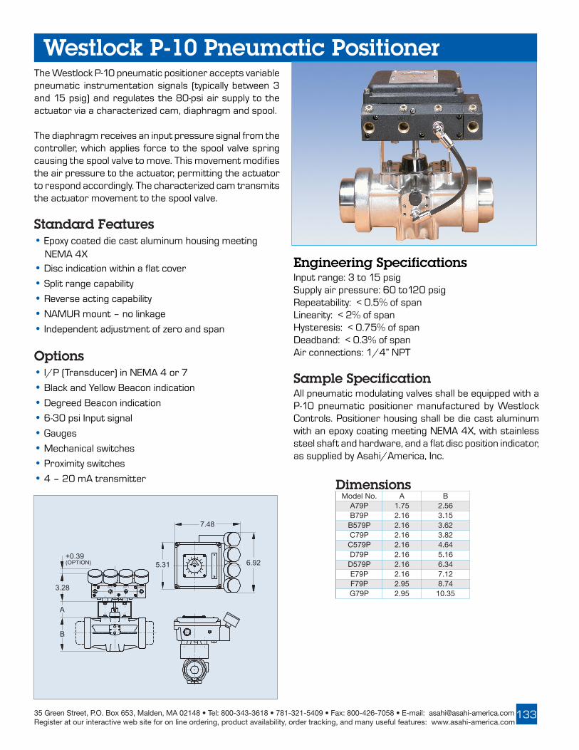
35 Green Street, P.O. Box 653, Malden, MA 02148 • Tel: 800-343-3618 • 781-321-5409 • Fax: 800-426-7058 • E-mail: [email protected] at our interactive web site for on line ordering, product availability, order tracking, and many useful features: www.asahi-america.com
133
The Westlock P-10 pneumatic positioner accepts variablepneumatic instrumentation signals (typically between 3and 15 psig) and regulates the 80-psi air supply to theactuator via a characterized cam, diaphragm and spool.
The diaphragm receives an input pressure signal from thecontroller, which applies force to the spool valve springcausing the spool valve to move. This movement modifiesthe air pressure to the actuator, permitting the actuatorto respond accordingly. The characterized cam transmitsthe actuator movement to the spool valve.
Standard Features• Epoxy coated die cast aluminum housing meeting NEMA 4X
• Disc indication within a flat cover
• Split range capability
• Reverse acting capability
• NAMUR mount – no linkage
• Independent adjustment of zero and span
Options• I/P (Transducer) in NEMA 4 or 7
• Black and Yellow Beacon indication
• Degreed Beacon indication
• 6-30 psi Input signal
• Gauges
• Mechanical switches
• Proximity switches
• 4 – 20 mA transmitter
Westlock P-10 Pneumatic Positioner
Engineering SpecificationsInput range: 3 to 15 psigSupply air pressure: 60 to120 psigRepeatability: < 0.5% of spanLinearity: < 2% of spanHysteresis: < 0.75% of spanDeadband: < 0.3% of spanAir connections: 1/4” NPT
Sample SpecificationAll pneumatic modulating valves shall be equipped with aP-10 pneumatic positioner manufactured by WestlockControls. Positioner housing shall be die cast aluminumwith an epoxy coating meeting NEMA 4X, with stainlesssteel shaft and hardware, and a flat disc position indicator,as supplied by Asahi/America, Inc.
+0.39(OPTION)
3.28
A
B
7.48
6.92 5.31
S OUT 2 OUT 1 INPUT
Dimensions.oNledoM A B
P97A 57.1 65.2P97B 61.2 51.3P975B 61.2 26.3P97C 61.2 28.3P975C 61.2 46.4
P97D 61.2 61.5P975D 61.2 43.6
P97E 61.2 21.7P97F 59.2 47.8P97G 59.2 53.01

ASAHI/AMERICARev. C 03-05
134
E
H
180˚Pneumatic Actuator
The HT Series Pneumatic Actuator has been specificallydesigned for valves that are installed on or close tofurnaces, boilers, kilns, reactor vessels; or valves handlingthermal fluids in heat exchangers, thermal transferequipment, process vessels, etc. Typically the valves areinsulated however, conductive and radiant heat canincrease the temperature around the actuator to levelshigher than recommended for our standard pneumaticactuator (195ºF).With this in mind, the HT Series Actuator was developed.Dimensions and operation are the same as our standardSeries 79 Pneumatic Actuators however; the materialsof construction have been re-engineered to allow fortemperatures up to 450ºF.
Externals:Externals:Externals:Externals:Externals:The body and end caps are die-cast aluminum alloy speciallytreated to prevent deformation at high temperatures, andfully jacketed in Xylan®.
Internals:Internals:Internals:Internals:Internals:The shaft and pinion are 303 SS, the pistons arebichromated steel with graphite-filled PTFE piston guides,and FKM (VITON) O-rings. Spring return models have SSconcentric spring sets.
High TemperaturePneumatic Actuator
The 180º Actuator is for a 3-way or multiport valve,diverting flow from left port to right port and is availablewith an optional center-off position. This actuator is offeredin cataphoresis and rilsan coated aluminum (inside andoutside) with a steel rack and SS pinion. Mountingdimensions are the same as our standard pneumaticactuators (see page 130 for mounting details), outputtorques are different; please see table below.
Double Acting
Single ActingSingle ActingDouble Acting
.oNledoMtuptuOeuqroTSBL/NI
thgieWSBL
P97THB 991 2.3
P97THC 765 4.6
P97THD 5231 9.21
P97THE 6773 3.62
.oNledoMtuptuOeuqroT
sbl/ni
EsnoisnemiD
sehcnI
HsnoisnemiD
sehcnI
thgieWSBL
081-P97C 211 98.11 00.5 01
081-P97D 862 27.41 43.6 9.41
081-P97E 717 85.32 13.8 2.63
.oNledoMtuptuOeuqroT
sbl/ni
EsnoisnemiD
sehcnI
HsnoisnemiD
sehcnI
thgieWSBL
081-P97C 423 67.9 00.5 6.8
081-P97D 517 56.11 43.6 8.01
081-P97E 1781 64.81 13.8 3.12
.oNledoMtuptuOeuqroTSBL/NI
thgieWSBL
SP97THB 26 7.3
SP97THC 032 2.8
SP97THD 614 4.71
SP97THE 3341 14
Note: Torque based on 80psi Air Supply
Note: Torque based on 80psi Air Supply
Note: Torque based on 80psi Air Supply

35 Green Street, P.O. Box 653, Malden, MA 02148 • Tel: 800-343-3618 • 781-321-5409 • Fax: 800-426-7058 • E-mail: [email protected] at our interactive web site for on line ordering, product availability, order tracking, and many useful features: www.asahi-america.com
135
AS-i Bus System
AS-i (Actuator-Sensor Interface) offers many of thebenefits of more complex and costly bus systems, but doesit at a substantially lower cost and with greater simplicity.The Actuator-Sensor Interface is ideally suited forcontrolling valves, actuators and many other field devicesin your processing application. This interface can be usedfor stand-alone process control, or it can be used togetherwith a higher-level bus control system. AS-interface doesnot compete with higher-level bus systems; it should beseen as a complimentary system that offers low cost,reliable device control for binary and analog devices.Reliability, simplicity and interoperability make AS-interfacea cost effective connection/control solution, particularlywhere low installation costs is imperative. A single pair ofwires, which handles power and communications, is usedto control the network by means of “chaining” theactuators with the PLC. Each actuator (or device) will thenhave its own unique address within the system and onlythat device with the proper address will respond to systemcommands. AS-i is best known for its yellow flat cable, whichis pierced by insulation displacement connectors so thatthe expense of tees and complex connectors is avoided.Devices are simply clamped onto the cable.
Digital signals are encoded on this cable in a sinusoidalsignal, which has a very narrow frequency bandwidth.Filtering which is distributed through the networkrejects all extraneous frequencies, and in this way AS-ican be operated in electrically noisy environmentswithout experiencing transmission errors.The yellow flatcable carries low current (30 VDC) for input devices aswell as the AS-i signal. If power for outputs (such asenergizing relays) is required, an additional BLACK flatcable is available. Standard networking is capable of 62units with a distance up to 100 meters, and a cycle timeof 5ms. A maximum of 300 meters is achieved byinstalling repeaters. This system also responds well withproducts from other manufacturers, by installing agateway to “translate” the commands of higher-levelnetworks. This allows an existing system to be expandedsimply by using the AS-i networking system.There arevarious wiring structures which can be used with thissystem such as the “star”, “ring”, “branch”, “tree”, etc.All are practiced and acceptable, but the loop has adistinguished property; if there were a “break” in thenetwork cable the units would still cyclewould still cyclewould still cyclewould still cyclewould still cycle and the masterwould detect the loss of a node. This feature is unique tothe ring structure.

ASAHI/AMERICARev. C 03-05
136
Pneumatic SpecificationsMounting: ISO/NAMURConnection: M12 SSAS-i Current Draw: .16 AMPElectrical Design: 2-input/2-outputVoltage Range: 26.5-31.6 VDCSensor/Relay Supply: AS-iSensor Protection: NEMA 4XAir Connection: 1/4" FNPTSolenoid Coil: Epoxy encapsulatedSolenoid Protection: NEMA 4xReverse polarity protected
Sample SpecificationAll pneumatically actuated AS-interface systems shallhave a 2-input/2-output proximity sensor and a solenoiddirectly mounted to a Series 79 Actuator. The sensorshall be constructed of Pocan® Thermoplastic Polyester,NEMA 4X protection, operation and function LED’s,voltage range of 20-30 VDC, and a stainless steel M12socket connection to the network. The solenoid shallhave an anodized aluminum body with a 1/4" NPT airinlet, manual over ride, and NEMA 4X protection.Spool/piston shall be synthetic resin with NBR and FKMO-rings, and fitted with an epoxy-encapsulated coildirectly coupled to the proximity sensor, as supplied byAsahi/America Inc.
AS-i Bus System
Accessories• Master/Controller - AS-i• Master/Controller - Gateway• Power Supply• Addressing Unit• Operating Software• Yellow Communications Cable• Black Power Cable• Displacement Connectors• Displacement Splitter• Cable Clip
Standard Features• Low profile, compact package for ease in mounting where space limitations are an issue.• Actuators and accessories meet ISO and NAMUR Standards, therefore no special training is required for field installation/conversion.• M12 SS connection utilized for network interfacing - NEMA 4X rated.• No moving parts with proximity sensor triggered by a target puck.• Sealed proximity switch so open cavity condensation is not an issue.• Each actuator has visual indication and proximity feedback to the PLC.• Each component meets NEMA 4X.• Low power consumption allows power and data communications via the same two-wire cable.• A system of 31 valves requires less than 5 amps of AS-i power.• Expandability with gateway and/or insulation displacement connector.• 5 ms reaction time from PLC to cycling of unit.• Conformance to AS-i Certificate ZU15101.

35 Green Street, P.O. Box 653, Malden, MA 02148 • Tel: 800-343-3618 • 781-321-5409 • Fax: 800-426-7058 • E-mail: [email protected] at our interactive web site for on line ordering, product availability, order tracking, and many useful features: www.asahi-america.com
137
AS-i Bus System Electric SpecificationsMounting: Inside actuator housingConnection: M12 SS*AS-i Current Draw: .13 AMPElectrical Design: 4-input/4-outputVoltage Range: 26.5-31.6 VDCSensor/Relay Supply: AS-iRelay Outputs: 12VAC/VDC, 24 VAC/VDC 115 VAC, or 220 VACActuator Protection: NEMA 4x, 7 & 9Reverse polarity protected*Consult factory for specifications
Sample SpecificationAll electrically actuated AS-interface systems shall havea double proximity switch and a PCB card installed insideof the Series 92 Actuator without compromising theprotection (NEMA 4X, 7 &9). The proximity switch shallhave 2 independent spst contacts triggered by thestandard actuator cams and enclosed in a Pocan®
thermoplastic polyester housing NEMA 4X rated. ThePCB card shall be short circuit protected, reversepolarity protected with 4 relay outputs. Relay outputsshall be rated 6 Amps and accept 12VAC/VDC, 24VAC/VDC, 115 VAC, OR 220 VAC. The PCB card shall wiredirect to an M12 connector for acceptance of AS-ipower/signal, as supplied by ASAHI/America Inc..
Standard Features• AS-i components are installed inside standard actuator housing; actuator dimensions remain unchanged.• M12 SS connection utilized for network interfacing – NEMA 4X rated.• No moving parts with proximity sensor triggered by cams.• Each actuator has visual indication and proximity feedback to the PLC.• Each component meets NEMA 4X.• Low power consumption allows power and data communications via the same two-wire cable.• A system of 31 valves requires less than 5 amps of AS-i power.• Expandability with gateway and/or insulation displacement connector.• 5 ms reaction time from PLC to cycling of unit.• Conformance to AS-i Certificate ZU11601
Accessories• Master/Controller - AS-i• Master/Controller - Gateway• Power Supply• Addressing Unit• Operating Software• Yellow Communications Cable• Black Power Cable• Displacement Connectors• Displacement Splitter• Cable Clip

ASAHI/AMERICARev. C 03-05
138
MOTOR
9.25
5.44
9.06
8.22
B
C1
A
SENSOR
AS-iINTERFACEBOARD
AS-iCONDUITCONNECTOR (M12)
SHAFT
IN
AS-iCONNECTOR(M12)
21/20PROXIMITYSENSOR
TARGET PUCKANDVISUAL INDICATION
SOLENOID
Electric Actuators
Dimensions (IN.) Dimensions (IN.)seireS A B 1C
NP97A 33.4 92.4 25.3
NSP97A 33.4 56.5 25.3
NP97B 29.4 29.4 87.3
NSP97B 29.4 03.6 87.3
NP975B 93.5 57.5 41.4
NSP975B 93.5 46.7 41.4
NP97C 95.5 61.7 22.4
NSP97C 95..5 92.9 22.4
NP975C 24.6 99.7 14.4
NSP975C 24.6 21.01 14.4
seireS A B 1C
NP97D 39.6 12.9 96.4
NSP97D 39.6 82.21 96.4
NP975D 11.8 78.01 21.5
NSP975D 11.8 52.41 21.5
NP97E 09.8 47.31 57.5
NSP97E 09.8 68.81 57.5
NP97F 15.01 84.71 77.6
NSP97F 15.01 45.32 77.6
NP97G 21.21 36.02 63.7
NSP97G 21.21 23.72 63.7
AS-i Bus System

35 Green Street, P.O. Box 653, Malden, MA 02148 • Tel: 800-343-3618 • 781-321-5409 • Fax: 800-426-7058 • E-mail: [email protected] at our interactive web site for on line ordering, product availability, order tracking, and many useful features: www.asahi-america.com
139
ARMATURE
WINDING
GEAR TRAIN
OUTPUT SHAFTOF GEAR BOX
Electric Actuators IntroductionBasics of OperationBasics of OperationBasics of OperationBasics of OperationBasics of OperationAn electric actuator is basically a geared motor. Themotor can be of various voltages and is the primarytorque-generating component. To prevent heat damagefrom overwork or excessive current draw, electricactuator motors are usually equipped with a thermaloverload sensor embedded in the motor windings. Thissensor is wired in series with the power source and opensthe circuit should the motor be overheated, then closesthe circuit when the motor reaches a safe operatingtemperature.
An electric motor consists of an armature, an electricalwinding, and a gear train. When power is supplied to thewinding, a magnetic field is generated causing thearmature to rotate. The armature will rotate as long asthere is power to the windings when the power is cut, themotor stops. Standard end of travel limit switches, whichare a necessity for an electric actuator handle this task.
Electric actuators rely on a gear train, which is coupleddirectly from the motor to enhance the motor torque anddictate the output speed of the actuator. The only way tochange the output speed is to install a cycle length controlmodule. This module allows an increase in cycle time only.If a decrease in cycle time is required, an alternateactuator with the desired cycle time and proper outputtorque must be used.
Types of MotorsTypes of MotorsTypes of MotorsTypes of MotorsTypes of MotorsThere are two (2) types of motors used for electricactuators; uni-directional and bi-directional (commonlyknown as reversing motors).
• Uni-directional motors are motors in which the armature rotates in one (1) direction, causing the valve to rotate in one direction. These actuators are typically used with a ball valve and rotate in 90 or 180 degree increments strictly for an on/off type of service.
• Reversing motors are motors in which there are two (2) sets of windings allowing the armature to rotate in either direction depending on which set of windings is powered. One (1) set of windings controls the clockwise direction for closing a valve, while the other set of winding controls the counter-clockwise direction for opening the valve. A major benefit of a bi-directional actuator is precise flow control, as the actuator is not required to travel the full stroke to begin the reverse stroke.
Electric or Pneumatic?Electric or Pneumatic?Electric or Pneumatic?Electric or Pneumatic?Electric or Pneumatic?The pneumatic actuator will probably continue to bethe actuator of choice in the process industry howeverthere are many applications where an electric actuatorshould be considered.
No Air Supply:No Air Supply:No Air Supply:No Air Supply:No Air Supply:In many remote installations, it may be impractical to runan air supply line and maintain it.
Colder Climate:Colder Climate:Colder Climate:Colder Climate:Colder Climate:Compressed air systems are vulnerable to freezing andclogging of the air lines, or potentially damaging theequipment if located in a climate that frequently seestemperatures below freezing.
PLC/DCS Controlled Process:PLC/DCS Controlled Process:PLC/DCS Controlled Process:PLC/DCS Controlled Process:PLC/DCS Controlled Process:In the past, standard engineering practice called forpneumatically actuated valves even when the rest of thesystem was electronically controlled. This required aconversion from electric to pneumatic (I/P) that madesystems more complicated to startup and maintain. Withthe increasing popularity of PLC/DCS systems, manyprocess and instrumentation engineers are nowspecifying fully electronic actuation packages.
Installation Savings:Installation Savings:Installation Savings:Installation Savings:Installation Savings:The cost to prepare a plant for pneumatically actuating afew valves (compressor, regulators, air lines, etc) farexceeds the cost of using electrically actuated valves.***** Even though pneumatic actuators are used, electricityis still required to energize the solenoid valve coils thatcycle the pneumatic actuators.

ASAHI/AMERICARev. C 03-05
140
Series 92 Electric ActuatorStandard Features•Motor:Motor:Motor:Motor:Motor: Reversing, brushless, capacitor run 115 VAC 50/60 Hz, single phase
• Overload protection:Overload protection:Overload protection:Overload protection:Overload protection: Integral thermal overload protection for motor windings with automatic reset
• Gear train:Gear train:Gear train:Gear train:Gear train: Permanently lubricated, solid gear that is Rockwell hardened
• Corrosion resistant housing:Corrosion resistant housing:Corrosion resistant housing:Corrosion resistant housing:Corrosion resistant housing: Thermally bonded baked powder coating with stainless steel trim
• ISOISOISOISOISO mounting configuration
• Conduit:Conduit:Conduit:Conduit:Conduit: Two 1/2” NPT conduit entries to eliminate cross feed between control, feedback, and power signals
• Position indication:Position indication:Position indication:Position indication:Position indication: Highly visible beacon position indicator for positive position of valve, even at a distance
• Declutchable manual override:Declutchable manual override:Declutchable manual override:Declutchable manual override:Declutchable manual override: Pull up on indicator knob, insert 5/8” wrench onto flats and rotate in the appropriate direction (CCW for open, CW for close). Models with handwheel override do not require a wrench. Simply push down on handwheel until engaged with cam and rotate
• Limit switches:Limit switches:Limit switches:Limit switches:Limit switches: Standard end of travel limit switches can be used for light indication (not to be use with PLC for position confirmation)
• Enclosure:Enclosure:Enclosure:Enclosure:Enclosure: Combination NEMA 4X, 7 & 9 enclosure for use in various environments
• Corrosion resistant mounting:Corrosion resistant mounting:Corrosion resistant mounting:Corrosion resistant mounting:Corrosion resistant mounting: Mounting is with PPG or stainless steel bracket, stainless steel coupling, and stainless steel hardware
• CE compliant motor:CE compliant motor:CE compliant motor:CE compliant motor:CE compliant motor: All 115 VAC and 230 VAC motors are CE compliant and stamped as such
• Extended duty cycles:Extended duty cycles:Extended duty cycles:Extended duty cycles:Extended duty cycles: Our extended duty cycles are ideal for modulating and high cycling applications
• Output torque:Output torque:Output torque:Output torque:Output torque: Series 92 Electric Actuators have an
output torque range from 400 in/lbs to 2000 in/lbs
Options• Auxiliary (additional) limit switches
• Feedback potentiometer
• Heater and thermostat
• 4-20 mA Positioner (Modulating PCB)
• Mechanical brake
• 4-20 output source (Transmitter)
• Cycle length control module (CLC)
• Two-wire control
• Failsafe battery back up (Protek)
• Voltages
• Local Remote Station
See page 148 for more details regarding options.
Engineering Data
Engineering SpecificationsSize: S92, A92, B92, C92Torque: 400-2000 in/lbsVoltage: 120 VAC 1Ph 50/60 HzAmp Draw: S92, B92 .5A, A92 .8A, C92 1.0AConduit Entry: Two (2) 1/2" NPTMax Ambient Temperature: 150ºFSwitches: Two (2) single pole, double throw (2SPDT)15 amp ratedCycle Time per 90º: S92, A92: 10 seconds
B92, C92: 25 seconds
Note: Amp rating is considered locked rotor. Duty cycles are for ambient temperature (73ºF)
ATADGNIREENIGNE
ledoM euqroT)sbl/ni(
caV511 caV032 cdV21 cdV42 caV21 caV42 repemiTelcyCseergeD09)sdnoces(
thgieW)sbl(pmA
warDytuDelcyC
pmAwarD
ytuDelcyC
pmAwarD
ytuDelcyC
pmAwarD
ytuDelcyC
pmAwarD
ytuDelcyC
pmAwarD
ytuDelcyC
29S 004 5.0 %001 4.0 %001 0.2 %57 0.4 %57 0.2 %57 0.3 %57 01 3.5129A 007 8.0 %57 6.0 %57 0.2 %57 0.4 %57 0.2 %57 0.3 %57 01 3.5129B 0011 5.0 %001 4.0 %001 0.2 %57 0.4 %57 0.2 %57 0.3 %57 52 3.5129C 0002 0.1 %05 6.0 %05 0.2 %57 0.4 %57 0.2 %57 0.3 %57 52 3.81

35 Green Street, P.O. Box 653, Malden, MA 02148 • Tel: 800-343-3618 • 781-321-5409 • Fax: 800-426-7058 • E-mail: [email protected] at our interactive web site for on line ordering, product availability, order tracking, and many useful features: www.asahi-america.com
141
52
51
18
35
4
5
27
28
30
25
9
10
8
26
1
49 44
39
18A
17
19
45
36
29 50
38
23
24A
24B
2
3
14
11
38
16
32
31
15
6
7
Cover: Powder Coated Diecast Aluminium
Cover Screw: Stainless Steel
Output Shaft:Electroless Nickel Plated
Base:Powder Coated Diecast Aluminium
11.60(MODEL C) 9.06
(MODEL S, A & B)
10.00
.550 DEPTH
9.19
8.22
R.125
2.75 BCD
.948+.002- .000 SQ
M8x.50DEPTH4 HOLES
Series 92 Electric Actuator
Sample SpecificationAll Series 92 electric actuators shall have a thermallyprotected, bi-directional (reversing type), capacitor runmotor with a permanently lubricated gear train. 115 Vac& 220 Vac motors shall conform to CE and be indicatedon motor housing. Actuator shall have solid, heat-treatedgearing encompassed in a baked powder coated die castaluminum housing with stainless steel trim, which meetsNEMA 4X, 7 & 9. Each actuator to have a declutchablemanual override, visual position indication, and ISOmounting configuration as manufactured by Asahi/America Inc.
Parts ListTSILSTRAP
.ON traPrebmuN
.SCPnoitpircseD
29S 29A 29B 29C1 0291047 1 1 1 1 esaB3 0601047 1 1 1 1 etalPesaB4 0491047 1 1 1 1 revoC6 0091047 1 1 1 - niaMtfahSA6 5091047 - - - 1 niaMtfahS7 0631047 2 2 2 2 niP8 0821047 - - 1 1 butStfahS9 3002047 - - 1 1 B1raeGrupS01 2002047 - - 1 1 A1raeGrupS11 0041047 1 1 1 1 noiniPraeG41 0831047 1 1 1 1 niaMraeG51 0021047 1 1 1 - rennItfahSA51 0121047 - - - 1 rennItfahS61 0811047 1 1 1 1 reniateRtfahS71 0031047 1 1 1 1 rewoLbonK81 0231047 1 1 1 - reppUbonKA81 5991047 - - - 1 leehwdnaH91 0621047 1 1 1 1 ralloC32 0841047 2 2 2 2 maCA42 0241047 1 1 1 1 8-1kcolBlanimreTB42 5241047 1 1 1 1 61-9kcolBlanimreT52 0641047 2 2 2 2 hctiwS62 0651047 1 1 1 1 revoC/esaBgniR-O72 8492047 1 - 1 1 DFm2.4roticapaCA72 4002047 - 1 - - DFm7.6roticapaC82 8003047 - - - 1 DFm6.7roticapaC92 0251047 1 1 1 1 roticapaCpmalC03 0431047 1 1 1 1 rotoM13 0521047 1 1 1 1 llehS23 0221047 1 1 1 - gnirpSA23 0321047 - - - 1 gnirpS53 0861047 3 3 3 3 wercSralloC63 0461047 8 8 8 8 wercSrevoC83 0881047 1 1 3 3 23/3ffurdooW,yeK93 0071047 1 1 1 1 wercSteSbonK44 0401047 1 1 1 1 esaBlaeS54 0411047 1 1 1 1 revoClaeS15 5841047 - - - 1 maCleehwdnaH25 9710018 - - - 2 wercSteSmaC

ASAHI/AMERICARev. C 03-05
142
Series 94 Electric Actuator
Sample SpecificationAll Series 94 electric actuators shall have a thermallyprotected, bi-directional (reversing type), capacitor runmotor with a permanently lubricated gear train. 115 Vac& 230 Vac motors shall conform to CE and be indicatedon motor housing. Actuator shall have a Zytel FR50engineered resin housing with stainless steel trim, whichmeets NEMA 4X. Each actuator to have a declutchablemanual override, visual position indication, and ISOmounting configuration as manufactured by Asahi/America Inc.
Engineering SpecificationsSize: A94, B94Torque: 150-300 in/lbsVoltage: 120 VAC 1Ph 50/60 HzAmp Draw: A94 .5A, B94 .8AConduit Entry: Two (2) 1/2" NPTMax Ambient Temperature: 150ºFSwitches: Two (2) single pole, double throw (2SPDT)15 amp ratedCycle Time per 90º: A94, B94: 5 seconds
Standard Features• Motor:Motor:Motor:Motor:Motor: Reversing, brushless, capacitor run 115 VAC 50/60 Hz, single phase
• Overload protection:Overload protection:Overload protection:Overload protection:Overload protection: Integral thermal overload protection for motor windings with automatic reset
• Gear train:Gear train:Gear train:Gear train:Gear train: Permanently lubricated
• Corrosion resistant housing:Corrosion resistant housing:Corrosion resistant housing:Corrosion resistant housing:Corrosion resistant housing: Zytel FR50 engineered resin with stainless steel trim
• ISOISOISOISOISO mounting configuration
• Conduit:Conduit:Conduit:Conduit:Conduit: Two 1/2" NPT conduit entries to eliminate cross feed between control, feedback, and power signals
• Position indication:Position indication:Position indication:Position indication:Position indication: Highly visible position indicator for positive position of valve, even at a distance
• Declutchable manual override:Declutchable manual override:Declutchable manual override:Declutchable manual override:Declutchable manual override: Push down on handle and rotate in the appropriate direction (CCW for open, CW for close)
• Limit switches:Limit switches:Limit switches:Limit switches:Limit switches: Standard end of travel limit switches can be used for light indication (not to be use with PLC for position confirmation)
• Corrosion resistant mounting:Corrosion resistant mounting:Corrosion resistant mounting:Corrosion resistant mounting:Corrosion resistant mounting: Mounting is with PPG or stainless steel bracket, stainless steel coupling, and stainless steel hardware
• CE compliant motor:CE compliant motor:CE compliant motor:CE compliant motor:CE compliant motor: All 115 VAC and 230 VAC motors are CE compliant and stamped as such
• Extended duty cycles:Extended duty cycles:Extended duty cycles:Extended duty cycles:Extended duty cycles: Our extended duty cycles are ideal for modulating and high cycling applications
• Output torque:Output torque:Output torque:Output torque:Output torque: Series 94 Electric Actuators have an
output torque range from 150 in/lbs to 300 in/lbs
Engineering Data
Options• Auxiliary (additional) limit switches
• Feedback potentiometer
• Heater and thermostat
• 4-20 mA Positioner (Modulating PCB)
• Mechanical brake
• 4-20 output source (Transmitter)
• Cycle length control module (CLC)
• Two-wire control
• Center-off
• Failsafe battery back up (Protek)
• Voltages
• Local Remote Station
See page 148 for more details regarding options.
Note:: Amp rating is considered locked rotor. Duty cycles are for ambient temperature (73ºF)
ATADGNIREENIGNE
ledoM euqroT)sbl/ni(
caV511 caV032 cdV21 cdV42 caV21 caV42 repemiTelcyCseergeD09)sdnoces(
thgieW)sbl(pmA
warDytuDelcyC
pmAwarD
ytuDelcyC
pmAwarD
ytuDelcyC
pmAwarD
ytuDelcyC
pmAwarD
ytuDelcyC
pmAwarD
ytuDelcyC
49A 051 5.0 %001 4.0 %001 0.2 %57 0.4 %57 0.2 %57 0.4 %57 5 5.349B 003 8.0 %57 6.0 %57 0.2 %57 0.4 %57 0.2 %57 0.4 %57 5 5.3

35 Green Street, P.O. Box 653, Malden, MA 02148 • Tel: 800-343-3618 • 781-321-5409 • Fax: 800-426-7058 • E-mail: [email protected] at our interactive web site for on line ordering, product availability, order tracking, and many useful features: www.asahi-america.com
143
34
13A
35
27
21
22
15
14
13B
28
33
18
17
16
20
7
9
8
10
19
23
26
6
5
4
3
1
2
Cover: Molded ZYTEL FR50
Cover Screw: Stainless Steel
Base:Molded ZYTEL FR50
Output Coupling:Stainless Steel
7.34
5.67R.125
1.97 BCD
6.06
.60 DEPTH
6.37
+.002 -.000
SQ.788
M6x.50DEPTH4 HOLES
Series 94 Electric ActuatorParts List
TSILSTRAP
.ON traPrebmuN ytitnauQ noitpircseD
1 2003047 1 esaB2 0003047 1 laeSesaB3 7103047 1 gnilpuoCtuptuO4 5003047 2 teksaGgnilpuoC5 4003047 1 rotoM6 2203047 2 wercSrotoM7 1103047 1 etalPesaB8 0241047 1 8-1kcolBlanimreT9 5241047 1 61-9kcolBlanimreT01 0061047 4 wercSkcolBlanimreTA31 8491047 1 49A-roticapaCFm2.4B31 4002047 1 49B-roticapaCFm7.641 0641047 2 hctiwStimiL51 0261047 2 wercShctiwStimiL61 6103047 1 tfahSretuO71 6003047 2 teksaGtfahSretuO81 9003047 2 gniRgniniateR91 8103047 2 ffodnatS02 4103047 2 wercSetalPesaB12 0841047 2 maC22 0471047 4 wercSteSmaC32 0103047 1 niP62 7003047 1 teksaGesaB72 1003047 1 revoC82 0203047 1 laeSrevoC33 2303047 8 wercSrevoC43 3003047 1 eldnaH53 0071047 1 wercSeldnaH

ASAHI/AMERICARev. C 03-05
144
12.36
3.30
3.33
9.00
2x3/4 NPTF
2.69
2.06
8.364.18
2.06
2.69
10.5
13.5Max
2.14
10.0 CLEARANCEFOR COVER REMOVAL
Engineering Data
Standard Features• Motor: Motor: Motor: Motor: Motor: Reversing, brushless, capacitor run 115 VAC 50/60 Hz, single phase
• Overload protection:Overload protection:Overload protection:Overload protection:Overload protection: Integral thermal overload protection for motor windings with automatic reset
• Gear train:Gear train:Gear train:Gear train:Gear train: Permanently lubricated
• Conduit: Conduit: Conduit: Conduit: Conduit: Two 3/4" NPTF conduit entries to eliminate cross feed between control, feedback and power signals
• Declutchable manual override: Declutchable manual override: Declutchable manual override: Declutchable manual override: Declutchable manual override: Push down on handwheel until engaged with cam and rotate
• Limit switches: Limit switches: Limit switches: Limit switches: Limit switches: Standard end of travel limit switches can be used for light indication (not to be used with PLC for position confirmation)
Two (2) auxiliary (additional) limit switches• Enclosure: Enclosure: Enclosure: Enclosure: Enclosure: NEMA 4X
• Corrosion resistant mounting: Corrosion resistant mounting: Corrosion resistant mounting: Corrosion resistant mounting: Corrosion resistant mounting: Mounting is with stainless steel bracket, stainless steel coupling and stainless steel hardware
• Output torque:Output torque:Output torque:Output torque:Output torque: Series 87 Electric Actuators have an
output torque range from 5000 in/lbs to
10,000 in/lbs
• Mechanical BrakeMechanical BrakeMechanical BrakeMechanical BrakeMechanical Brake
Options• Feedback potentiometer
• Heater and thermostat
• 4-20 mA Positioner (Modulating PCB)
• Mechanical brake
• 4-20 output source (transmitter)
• Cycle length control module (CLC)
• Two-wire control
• Center-off
• Voltages
• Local Remote Station
See page 148 for more details regarding options.
Engineering SpecificationsSize: E87, F87Torque: 5,000-10,000 in/lbsVoltage: 120 VAC 1Ph 50/60 HzAmp Draw: E87 1.7, F87 2.2Conduit Entry: Two (2) 3/4" FNPTMax Ambient Temperature: 150ºFCycle Time per 90o : E87, F87: 30 seconds
Sample SpecificationAll Series 87 electric acutuators shall have thermallyprotected, bi-directional (reversing type), capacitor runmotor with a permanently lubricated gear train. Actuatorshall have planetary gearing encompassed in adiecast aluminum housing with stainless steel trim,meeting NEMA 4X. Each actuator shall have amanual override, visual position indication, two (2)auxiliary limit switches and a mechanical brake as suppliedby Asahi/America Inc..
Series 87 Electric Actuator
Note: Amp rating is considered locked rotor Duty cycles are for ambient temperature (73ºF)
ATADGNIREENIGNE
ledoMcaV511 caV032
elcyCrepemiT
09seergeD)sdnoces(
thgieW)sbl(euqroT
)sbl/ni(pmAwarD
ytuDelcyC
pmAwarD
ytuDelcyC
78E 000,5 7.1 %05 0.1 %05 03 4378F 000,01 2.2 %05 2.1 %05 03 43

35 Green Street, P.O. Box 653, Malden, MA 02148 • Tel: 800-343-3618 • 781-321-5409 • Fax: 800-426-7058 • E-mail: [email protected] at our interactive web site for on line ordering, product availability, order tracking, and many useful features: www.asahi-america.com
145
1
2
3
4
5
6
7
8
9
10
1
1
1
1
OPEN CLOSE
BLK
BLK
BLK
12
13
HAND AUTOOFF
12BLK/RED
WHT/RED
XO
OX
13
1
2
3
7
XOO
XOO
RED/BLK
RED
ORANGE
2
3
RED
ORANGE
OOX
2
3
OOX
OOX
OOX
XOO
RED/BLK
REMOTE OPEN
ORG WHT
REMOTE CLOSE
ORG
8
9
8
9
GRN/BLK
ORANGE/BLK
11
14
BLK/WHT
RED/WHT
BLU/BLK
GRN/WHT
10
15
REMOTE POSITIONSTATUS
LOCAL POSITIONSTATUS
WHT
BLU
LIMIT
LIMIT
CLOSE
OPEN
4
5
2
1
3
4
5
BLUE
WHT/BLK
G
R
ACTUATOR
WHT
WHT
17
17
17
OPEN
CLOSE
17 GND
120 VAC
TroubleshootingTroubleshootingWhat if there is no output, but the motor runs?What if there is no output, but the motor runs?What if there is no output, but the motor runs?What if there is no output, but the motor runs?What if there is no output, but the motor runs?
1. Manual override engaged. Disengage.2. Valve stem broken. Replace stem as per
appropriate valve IOM Manual.What if valve does not cycle?What if valve does not cycle?What if valve does not cycle?What if valve does not cycle?What if valve does not cycle?
1. No power source to actuator. Check for power.2. Power source disconnected. Check for broken wire, loose connection or no connection as per appropriate wiring diagram.3. Mechanical brake jammed or misaligned. Check alignment of brake assembly.
What if there is water and/or moisture inside of theWhat if there is water and/or moisture inside of theWhat if there is water and/or moisture inside of theWhat if there is water and/or moisture inside of theWhat if there is water and/or moisture inside of theunit?unit?unit?unit?unit?
1. Conduit fitting installed improperly. Re-install correctly.2. Base gasket damaged or installed improperly. Check gasket and replace if necessary.3. Temperature swings of more than 15 degrees F. Install heater and thermostat to eliminate condensation.4. Unit has been submerged. Raise unit above liquid level.
What if unit is oscillating?What if unit is oscillating?What if unit is oscillating?What if unit is oscillating?What if unit is oscillating?1. Valve torque exceeds output torque of actuator. Check for chemical compatibility of valve, and flange torque.
What if motor hums and no output is observed?What if motor hums and no output is observed?What if motor hums and no output is observed?What if motor hums and no output is observed?What if motor hums and no output is observed?1. Foreign material caught in valve. Remove material and inspect valve for damaged and/or worn parts. Replace parts as necessary.2. Unit wired incorrectly (simultaneously powering open and closed). Check wiring as per appropriate wiring diagram.3. Capacitor worn. Replace.
What if actuator “over-shoots” limit switches withoutWhat if actuator “over-shoots” limit switches withoutWhat if actuator “over-shoots” limit switches withoutWhat if actuator “over-shoots” limit switches withoutWhat if actuator “over-shoots” limit switches withoutstopping?stopping?stopping?stopping?stopping?
1. Actuators wired in parallel to each other. Please note that each actuator requires it’s own
individual power source.What if thermal overload frequently cuts out motor?What if thermal overload frequently cuts out motor?What if thermal overload frequently cuts out motor?What if thermal overload frequently cuts out motor?What if thermal overload frequently cuts out motor?
1. Frequency of operation exceeds duty cycle rating.Check cycling period.
2. Unit is oscillating. Refer to above.
Standard Features• Visual Light Indication
• NEMA 4X Enclosure Constructed of Fiberglass Polyester
• Stainless Steel Trim
• Captive Cover Gasket
• Captive Cover Screws
• Two (2) Position Selector Switch (open and close)
• Three (3) Position Selector Switch (hand, off, auto)
• 40ºF - 266ºF Temperature Range
• Can be used with any Electric Actuator
(must specify before placing order)
Options• NEMA 7 Enclosure
• 316 Stainless Steel Enclosure
• Additional Terminal Block for Position Confirmation to PLC
• Contact Factory for Specific Applications
Local Remote Station

ASAHI/AMERICARev. C 03-05
146
Wiring Diagram for AC UnitsActuator Shown is Counter-Clockwise Extreme of Travel, or "Open" Position
NO
NC
SW2
BLUE
NO
NC
SW1
WHITE WHITE
BLUE
M
161514131211
AB
1098
BR
OW
N
YE
LL
OW
BL
UE
WH
ITE
BL
AC
K
7654321
L2
L1
Customer Provided Lights and Switches
ACVOLTS
See Important Note
BA161514131211109876876
Mechanical BrakeFeedbackHeater/ThermostatTwo Extra LimitSwitches with Cams
One Extra LimitSwitch with Cam
BL
UE
PU
PL
E
PIN
K
BL
UE
PU
PL
E
PIN
K
OR
AN
GE
GR
EE
N
BR
OW
N
BR
OW
N/W
HIT
E
GR
AY
WH
ITE
/BL
AC
K
Wiring for Optional Equipment
Wiring Diagram for DC UnitsActuator Shown is Counter-Clockwise Extreme of Travel, or "Open" Position
NO
NC
SW2
GRAY
NO
NC
SW1
BLACK
1615141312111098
BR
OW
N
YE
LL
OW
BL
UE
WH
ITE
BL
AC
K
7654321
L2
L1
Customer Provided Lights and Switches
DCVOLTS
GRAY
+
_
SNote:1. Each Actuator Must Be Powered Thru Its Own Individual Switch Contacts To Avoid Cross Feed.
2. Wiring As Shown Is For S92 & A92 Motor Leads at "A" And "B" are Reversed for B92 & C92.
3. Motor Has a Thermal Protector as Shown By in Diagram.
4. If 115vac & 220vac models are PLC driven, output contacts of PLC should be rated at minimum of 1.5 times required input voltage of actuator.
M '
Note:1. Wiring as Shown is For S92 & A92, Motor Leads are Reversed for B92 & C92.
Series 92 & 94 Wiring Schematics

35 Green Street, P.O. Box 653, Malden, MA 02148 • Tel: 800-343-3618 • 781-321-5409 • Fax: 800-426-7058 • E-mail: [email protected] at our interactive web site for on line ordering, product availability, order tracking, and many useful features: www.asahi-america.com
147
Wiring Diagram for Series 92 & 94 with Protek Failsafe Battery PackMotor Leads at J3 reversed for B + C92
HEATER + THERMOSTAT
REMOTE
(OPTIONAL)
CUSTOMERPROVIDED
LOCALREMOTESWITCH
NE
GA
TIV
E
NE
UT
RA
L
PO
SIT
IVE
HO
T
IMPUT
(-)
(+)1
2
3
4
5
6
J1 J3
F1 JP1
1 2
PC BOARD FS1-01
LOCAL
SW4J4
J2
2
1
1
2
3
RE
D
BLA
CK
MOTOR VDC
" - "
" + "
BLACK
RED
BLACK
EXTERNALBATTERY LAMP
RED
D12
406R LED RED
BATTERY
P/N P70AAS/FT-9-667 V=10.8 C=700MAH
SW5(OPTIONAL)
PC BOARD FS1-02NC
NO
J5
1 2 3
SW3COM
J7
OFF
ON1
2
3
J5A
4 5 6
EXTRA LIMIT SWITCHES / INTERIOR LIGHT CONTROL
NC
NO COM
RED
CLOSEDOPEN
GREEN
Wiring Diagram for Series 94 4-20mA
D9"OPEN"
D8"CLOSE"
PC BOARD QM1-1
123
J1
J2
"OPEN"COM
NC
SW2
NO
WHITE WH
ITE
BLU
E
PC BOARD QM1-2
J3
12
NC
SW1"CLOSE"
COM
NO
BLUE
A B
C D
FU
SE
D3
J2J3
FLA
T C
AB
LE
DA
TA
BA
SE
BLA
CK
WH
ITE
BRN/WHTGRAYWHT/BLK
(+)
(-)
POTENTIOMETER
2
1 3R1A
HE
AT
ER
1234
(+)
NE
UT
RA
L(-)
TH
ER
MO
STA
T
HO
T
NE
GA
TIV
E
PO
SIT
IVE
J1
POWER115VAC
SOURCE
123B
LU
E
L2 L1
C1
M
Note:1. R1A#1 and R1A#3 are Reversed for Series 92. R1B#1 and R1B#3 are Reversed for Series 92.2. Diagram for 4-20mA input, 4-20mA Output, or 4-20mA Input and Output.3. If Both Options are used jumpers can be installed for power from QM-1-1 to 4-20 Output Board.
1 2 3 4
POWER 115 VAC
J3
LD1 BR1R1
R3 U1
C2 VR1 C1
R4 C4
C3TT1R2
JP
TR1 REF
1 2 3 4 5 6
F1 J2 R6U3
U2C6
R7D4D3
D1
D2
REF R5R8
ZERO SPAN C5
NE
UT
RA
L (
-)
HO
T (
+)
POTENTIOMETER5
6
4R1B
J1
NE
GA
TIV
E (
-)
PO
SIT
IVE
(+)
OUTPUT 4-20mA4-20mA
Wiring Diagram for 4-20mA Output
Wiring Diagram for Series 87 115/230VAC
CUSTOMER PROVIDED LIGHTS AND SWITCHES
TB
6
1
L1
10
11
L2
12
4
2
5
3
7
8
9
COM
COM
COM
COM
NO
NC
NO
NC
NO
NC
NO
NC
SWITCH 4
SWITCH 2
SWITCH 1
SWITCH 3
HEATER
+t'
MANUALLOCKOUT SWITCH
THERMAL OVERLOADAUTOMATIC RESET
M3M2
M1
CAPACITOR
BRAKE
M
AC VOLTS
WHT/BLK
BRN
Series 92, 94 & 87 Wiring Schematics

ASAHI/AMERICARev. C 03-05
148
Options• Auxiliary limit switches: Auxiliary limit switches: Auxiliary limit switches: Auxiliary limit switches: Auxiliary limit switches: A total of four additional limit switches can be installed in theSeries 92, and a total of two additional limit switches can beinstalled in the Series 94 for interlocking with other equipmentor valves. Also widely used as valve position confirmation (endof travel) with a PLC, DCS, etc. These switches are SPDTwith a 15 amp rating.
• Feedback potentiometer: Feedback potentiometer: Feedback potentiometer: Feedback potentiometer: Feedback potentiometer:A 1000-ohm, 1 watt feedback potentiometer with 5% linearitycan be installed for position feedback. This varies from theauxiliary limit switches, as the feedback potentiometerprovides a varying degree opening percentage from 0-1000ohms.
• Heater and thermostat:Heater and thermostat:Heater and thermostat:Heater and thermostat:Heater and thermostat:A pre-wired heater and thermostat is available formaintaining a constant temperature inside of the actuatorhousing, eliminating condensation that can form when thetemperature fluctuates. It is imperative when the actuator isused in lower operating temperatures. The heater andthermostat are effective to –40 degrees F.
• Modulation PCB:Modulation PCB:Modulation PCB:Modulation PCB:Modulation PCB:A solid state PCB can be installed inside of the actuator forprecise modulating control. The standard PCB accepts 115VAC supply voltage and a 4-20 mA control signal but can beconfigured at the factory for various voltage supplies suchas 230 VAC, 24 VAC, etc and optional control signals suchas 0-10 VDC.
• Mechanical brake:Mechanical brake:Mechanical brake:Mechanical brake:Mechanical brake:This prevents oscillation typically found with rubber seatedButterfly Valves. The brake is installed on top of the motorarmature and is electro-mechanical. When power is appliedto the actuator, it is also applied to the brake, which releasesthe armature and allows the unit to cycle. When the poweris lost the springs within the brake lock the armature so thatit can no longer rotate, thus eliminating oscillation.
• 4-20 Transmitter:4-20 Transmitter:4-20 Transmitter:4-20 Transmitter:4-20 Transmitter:A solid state PCB installed in the unit will provide precisevalve position to a PLC, DCS, etc. via a 4-20 mA signal. This isan output signal from the actuator NOT a control signal tothe actuator. This does not require the use of a modulatingPCB as it is not for controlling the actuator only for reportingthe position to the appropriate piece of equipment.
• Cycle length control (CLC): Cycle length control (CLC): Cycle length control (CLC): Cycle length control (CLC): Cycle length control (CLC):This option allows the field adjustment of the cycle time up to10 minutes. The CLC can be configured at the factory for theopen cycle only, for the close cycle only, or for the combinationof open and close cycles.
• Two-wire control:Two-wire control:Two-wire control:Two-wire control:Two-wire control:The two-wire control option is a relay installed inside of theactuator for direct wiring to timers, level switches (SPST),or for replacing a solenoid valve. A constant power supplyand a SPST switch of some sort are required for cycling ofthe actuator. When the SPDT switch is closed, the valveopens, and vice versa.
• Center off:Center off:Center off:Center off:Center off:This option is used when a 90-degree “off” position is requiredwhile using a three-way ball valve. Two limit switches and twocams are installed in the unit (not to be confused with auxiliarylimit switches) and allow three positions for a three way valve;0 degrees or left port open, 180 degrees or right port open,and 90 degrees or both ports closed.
• Failsafe battery back up:Failsafe battery back up:Failsafe battery back up:Failsafe battery back up:Failsafe battery back up:A solid state PCB along with a rechargeable battery packare installed inside of the actuator. When power is lost, theunit will then travel to a pre-determined “fail position”. It isimperative that there be constant power to the unit to ensurethat the battery pack maintains a full charge. This optionallows for two selectable modes of operation:1) The unit can be operated as an on/off unit; power open/power close. A loss of power would result in the unit returningto the “fail position”.2) The unit can be operated similar to a solenoid valve; powerto one position and fail to the other position.
• Multiturn:Multiturn:Multiturn:Multiturn:Multiturn:This is more of a necessity than an option. When electricallyactuating a Gate or Diaphragm Valve, there must be multiplerevolutions to open and close the valve. Asahi installs a 10position rotary switch in parallel with the standard limitswitches to achieve this. By wiring in parallel, the rotary switchoverrides the standard switch allowing for multiplerevolutions. This parallel wiring also requires that bothswitches be open for the actuator to stop. This is only
available with the Series 92 Electric Actuator.
•Bus System:Bus System:Bus System:Bus System:Bus System:A single pair of wires, which handles power andcommunications, is used to control the network by meansof "chaining" the actuators with the PLC. Each actuator (ordevice) will then have its own unique address within thesystem and only that device with the proper address willrespond to system commands.
Options Series

35 Green Street, P.O. Box 653, Malden, MA 02148 • Tel: 800-343-3618 • 781-321-5409 • Fax: 800-426-7058 • E-mail: [email protected] at our interactive web site for on line ordering, product availability, order tracking, and many useful features: www.asahi-america.com
149
Pneumatic Actuation Ordering Information
Cataphoresis and Rilsan CoatedAluminum Body
316 Stainless Steel Body
High Temperature
180 Degree
Option Series 79
Glass-filled Polyamide
Examples:Examples:Examples:Examples:Examples:BP79PSN:B Size, Glass-filled Polyamide, Series 79P, Single Acting, No OptionsF79PW115A:F Size, Aluminum, Series 79P, Double Acting, with 115 VAC NEMA 4 Solenoid
eziS
AB5B
C5C
D5D
EFG
lairetaM edoC
nasliRdnasiserohpataCmunimulAdetaoC
-
edimayloPdellif-ssalG PSS613 S
detaoCnalyXpmeT-iH TH
seireS
P97
noitcA edoC
gnitcAelbuoD -gnitcAelgniS S
riAotriA gnirpSotriA
.oNledoM .oNmetI ledoM .oNmetINP97A 0010532 NSP97A 0019532NP97B 0001532 NSP97B 0000632NP975B 0011532 NSP975B 0010632NP97C 0002532 NSP97C 0001632NP975C 0012532 NSP975C 0011632
NP97D 0003532 NSP97D 0002632NP975D 0013532 NSP975D 0012632
NP97E 0004532 NSP97E 0003632NP97F 0005532 NSP97F 0004632NP97G 0008532 NSP97G 0008632
riAotriA gnirpSotriA
.oNledoM .oNmetI ledoM .oNmetINP97SB 0001932 NSP97SB 0005932NP97SC 0002932 NSP97SC 0006932NP97SD 0003932 NSP97SD 0007932
riAotriA gnirpSotriA
.oNledoM .oNmetI ledoM .oNmetINP97PA 0009732 NSP97PA 0000832NP97PB 0006732 NSP97PB 0002832NP97PC 0007732 NSP97PC 0003832NP97PD 0008732 NSP97PD 0004832
riAotriA gnirpSotriA
.oNledoM .oNmetI ledoM .oNmetINP97THB 0000732 NSP97THB 0003732NP97THC 0001732 NSP97THC 0004732NP97THD 0002732 NSP97THD 0005732
riAotriA gnirpSotriA
.oNledoM .oNmetI .oNledoM .oNmetI081-97C tlusnoC 081-NSP97C tlusnoC081-P97D yrotcaF 081-NSP97D yrotcaF081-P97E 081-NSP97E
Part Numbers Pneumatic ActuatorssnoitpO edoC
dioneloSoN N4AMENdioneloS
A511W)CAV511(
lbD4AMENhctiwStimiL
2M
isp51-3renoitisoP
2C
Am02-4renoitisoP
1C
snoitpO .oNmetI97:srenoitisoP
riA-riArofISP51-301P 1676142gnirpS-riArofISP51-301P 5136142
riA-riArofAm02-401-K 2676142gnirpS-riArofAm02-401K 0246142
snoitpOsuBi-SAgnirpS-riA,riA-riA97E-97A 0107042gnirpS-riA,riA-riA97G-97F 0407042
sehctiwStimiL)TDPS-2(elbuoD,VIAMEN 9773042)TDPS-2(elbuoD,IIVAMEN 0873042
sdioneloSCAV021,citsalP,VIAMEN 9771042CAV021,citsalP,IIVAMEN 0871042
:egatloVCDV21 9475142CDV42 0575142CAV21 1575142CAV42 2575142CAV022 3575142
:spotsmaCP97PB 0001222P97PC 0002222P97PD 0003222
P97E 0004222P97F 0005222P97G 0009342
eguaGhtiwrotalugeRretliF 0003212
Pneumatic Globe ControlgnirpSotriAlortnoCebolGdegnalF
eziS CVP PP EFTP FDVP2/1 5001052 5002052 0003052 50040524/3 7001052 7002052 7003052 7004052
1 0101052 0102052 0103052 01040524/11 2101052 2102052 2103052 21040522/11 5101052 5102052 5103052 5104052
2 0201052 0202052 0203052 02040522/12 5201052 5202052 5203052 5204052
3 0301052 0302052 0303052 03040524 0401052 0402052 0403052 0404052

ASAHI/AMERICARev. C 03-05
150
Electric Actuation Ordering Information
Options Series 92 and 94
Examples:Examples:Examples:Examples:Examples:AM92M2PXWJ:A Size, Series 92 with mechanical brake, 2 extra (auxiliary) limit switches and a feedback potentiometerB94WJ:B Size, Series 94, no options
(1) For open/close 120 VAC Units only, all others consult factory
eziS
SAMBMC
AB
MEMF
seireS
29292929
4949
MEMF
ledoM euqroTtuptuO rebmuNtraP
JWX29S sbL/nI004 0002712JWX29A sbL/nI007 0003712JWX29MB sbL/nI0011 0004712JWX29MC sbL/nI0002 0005712
ledoM euqroTtuptuO rebmuNtraP
JW49A sbL/nI051 0080702JW49B sbL/nI003 0090702
ledoM euqroTtuptuO rebmuNtraP
JW78ME sbL/nI0005 0005402JW78MF sbL/nI00001 0006402
gnitaRAMEN edoC
9,7,X4 JWX9,7,X4 JWX9,7,X4 JWX9,7,X4 JWX
X4 JWX4 JW
X4 JWX4 JW
euqroTtuptuO
00400700110002
051003
000500001
Part Numbers Electric Actuators
snoitpO #metI29 #metI49
hctiwStimiLartxE 1006212 3006212
hctiwStimiLartxEelbuoD 2006212 4006212
tatsomrehT&retaeH 1007212 1007212foorPnoisolpxEIIVAMEN
gnisuoH dradnatS A/N
retemnoitnetoPkcabdeeF 1009212 3009212
retemnoitnetoPkcabdeeFleuD 2009212 4009212
renoitisoPAM02-4 3670312 6670312
ecruoStuptuO02-4 0240312 1240312
tiK02-4rofnoitpoCDV01-0 0100312 0100312
lortnoChtgneLelcyC 1001312 3001312
ekarBlacinahceM 1006312 1006312
hctiwSFFOretneC 1002312 3002312
lortnoCeriW-2 1002012 8002012
kcaPyrettaBefasliaFketorP 0004512 1004512
)1(noitatSetomeR/lacoL 0000912 0000912
:segatloV
CDV21 9475312 9475312
CDV42 0575312 0575312
CAV21 1575312 1575312
CAV42 2575312 2575312CAV022 3575312 3575312suBi-SA 0297042 A/N
snoitpO edoC
hctiwStimiLartxE1 1MsehctiwStimiLartxE2 2MtatsomrehT&retaeH TH
toPkcabdeeF PtoPkcabdeeFlauD PD
ffOretneC OClotnoCeriW2 CW2
kcaPyrettaBefasliaF SFrenoitisoPAm02-4 1CrettimsnarTAm02-4 3C
Electric Globe ControlcirtcelElortnoCebolGdegnalF
eziS CVP PP EFTP FDVP2/1 5001022 5002022 0003022 50040224/3 7001022 7002022 7003022 7004022
1 0101022 0102022 0103022 01040224/11 2101022 2102022 2103022 21040222/11 5101022 5102022 5103022 5104022
2 0201022 0202022 0203022 02040222/12 5201022 5202022 5203022 5204022
3 0301022 0302022 0303022 03040224 0401022 0402022 0403022 0404022