2 visible-surface detection methods chapter 2avida.cs.wright.edu/courses/ceg477/ceg477_2.pdf2...
TRANSCRIPT
2-1Department of Computer Science and Engineering
2 Visible-Surface Detection Methods
Chapter 2
Visible-Surface Detection Methods
2-2Department of Computer Science and Engineering
2 Visible-Surface Detection Methods
2.1 OverviewWe saw in the previous chapter how to create 3-D scenes of different kind of objects. Since parts of some objects can be occluded by other objects within the scene, the computer has to determine which object is in the front to preserve a three-dimensional impression by the viewer.Therefore, this chapter will introduce some so-called visibility algorithms that do just that. In particular we will cover the following topics:
– Back-face culling– Z-buffer algorithm– Α-buffer algorithm– Ray casting

2-3Department of Computer Science and Engineering
2 Visible-Surface Detection Methods
2.1 OverviewThe goal of visibility algorithms is to determining as exactly as possible which parts of the scene that is to be rendered are visible and which are invisible from a given view point. Since a high frame rate is desirable, the user input, e.g. change of view point, should affect the rendered image immediately. Ideally, a real-time rendering of the scene should be achieved.Categories of visibility algorithms:
– Object spacetheoretically device independentnumerical precision depends on the machine precision
– Image spacedevice dependentnumerical precision depends on the resolution of the output device
2-4Department of Computer Science and Engineering
2 Visible-Surface Detection Methods
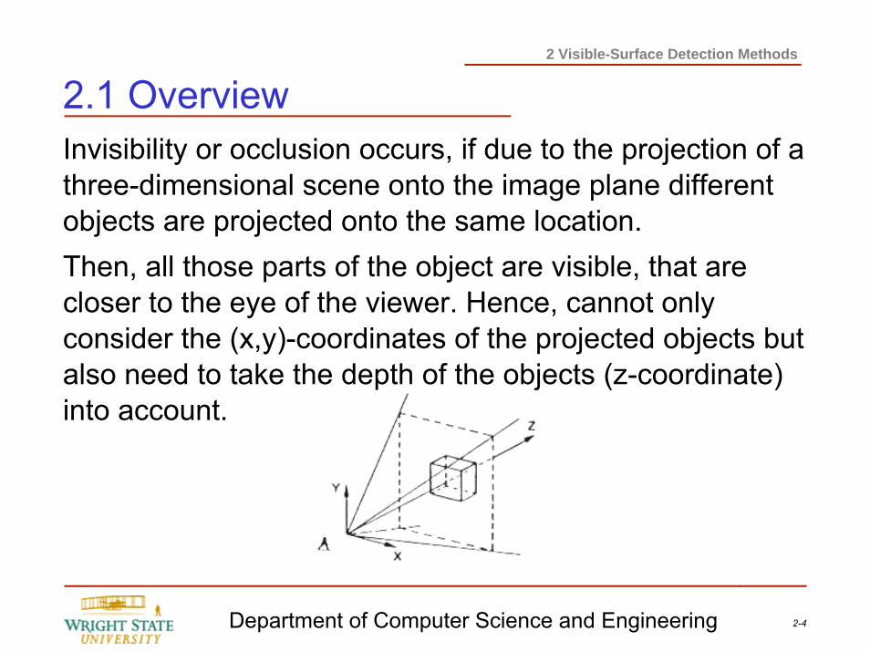
2.1 OverviewInvisibility or occlusion occurs, if due to the projection of a three-dimensional scene onto the image plane different objects are projected onto the same location.Then, all those parts of the object are visible, that are closer to the eye of the viewer. Hence, cannot only consider the (x,y)-coordinates of the projected objects but also need to take the depth of the objects (z-coordinate) into account.
2-5Department of Computer Science and Engineering
2 Visible-Surface Detection Methods
2.1 OverviewCoherenceIn this case, coherence means to exploit local similarities• Object coherence: if the projection of two objects do
not intersect, then their surfaces do not need to be tested against each other.
• Surface coherence: properties of neighboring points on a single surface often do not chance significantly.
• Depth coherence: the depth z(x,y) of a projected surface can often be computed incrementally.
2-6Department of Computer Science and Engineering
2 Visible-Surface Detection Methods
2.2 Back-face CullingDepending on the number and layout of objects within the scenes the removal of hidden surfaces can be quite costly. Therefore, a simple test which helps to reduce the complexity would be beneficial before using the visibility algorithm.
Such a simple but effective approach is back-face culling.
Depending on the position of the viewer the backsides of opaque objects are removed since these are occluded by the object itself, thus invisible.
2-7Department of Computer Science and Engineering
2 Visible-Surface Detection Methods
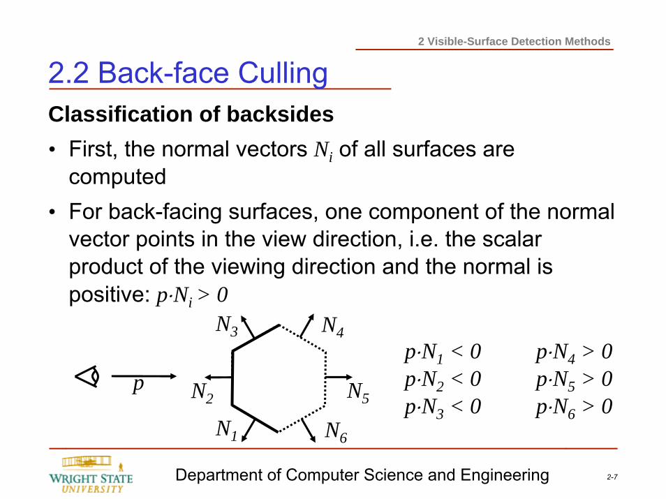
2.2 Back-face CullingClassification of backsides• First, the normal vectors Ni of all surfaces are
computed• For back-facing surfaces, one component of the normal
vector points in the view direction, i.e. the scalar product of the viewing direction and the normal is positive: p⋅Ni > 0
p N5
N4
N6N1
N2
N3p⋅N1 < 0 p⋅N4 > 0p⋅N2 < 0 p⋅N5 > 0p⋅N3 < 0 p⋅N6 > 0
2-8Department of Computer Science and Engineering
2 Visible-Surface Detection Methods
2.2 Back-face CullingProperties
– The number of polygons that are required for rendering the scene is approximately cut in half by removing the back-facing surfaces.
– The computational effort for computing the scalar product is minimal.
– If the scene is composed of a single convex polyhedron back-face culling already solves the visibility problem.
With scenes consisting of concave polyhedra or more than one convex polyhedron the objects can occlude themselves or each other which requires more complex algorithms.
2-9Department of Computer Science and Engineering
2 Visible-Surface Detection Methods
2.3 Visibility algorithmsKnown visibility algorithms:
– First solution of the hidden-line problem: Roberts, 1963object space algorithm for convex objects
– Area sub-division (divide and conquer): Warnock, 1969Exploits surface coherence using quadtrees
– Sample spans: Watkins, 1970Exploits the scan-line coherence
– Depth list: Newell et al., 1972Priority list algorithm within object space
Compared to the z-buffer algorithms above techniques did not gain very much popularity. This is mostly due to the versatility of the z-buffer algorithm. The listed algorithms all have certain limitations and can be applied only to specific scenes.
2-10Department of Computer Science and Engineering
2 Visible-Surface Detection Methods
2.4 Z-buffer algorithmZ-buffer algorithm [Catmull, 1975]
– Determines the visibility of pixels– Works within image space– Suitable for image output devices using rasters
Principle:From a functional point of view, the z-buffer algorithm finds for each pixel within image space the polygon which covers this specific pixel and the z-value is minimal, i.e. it is in the front of all other polygons (for this pixel).To implement the algorithm, additional memory is used (the so-called z-buffer) which stores for each pixel the currently smallest z-value.
2-11Department of Computer Science and Engineering
2 Visible-Surface Detection Methods
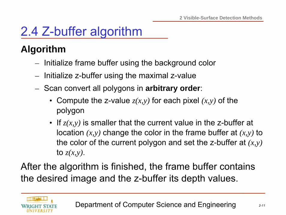
2.4 Z-buffer algorithmAlgorithm
– Initialize frame buffer using the background color– Initialize z-buffer using the maximal z-value– Scan convert all polygons in arbitrary order:
• Compute the z-value z(x,y) for each pixel (x,y) of the polygon
• If z(x,y) is smaller that the current value in the z-buffer at location (x,y) change the color in the frame buffer at (x,y) to the color of the current polygon and set the z-buffer at (x,y)to z(x,y).
After the algorithm is finished, the frame buffer contains the desired image and the z-buffer its depth values.
2-12Department of Computer Science and Engineering
2 Visible-Surface Detection Methods
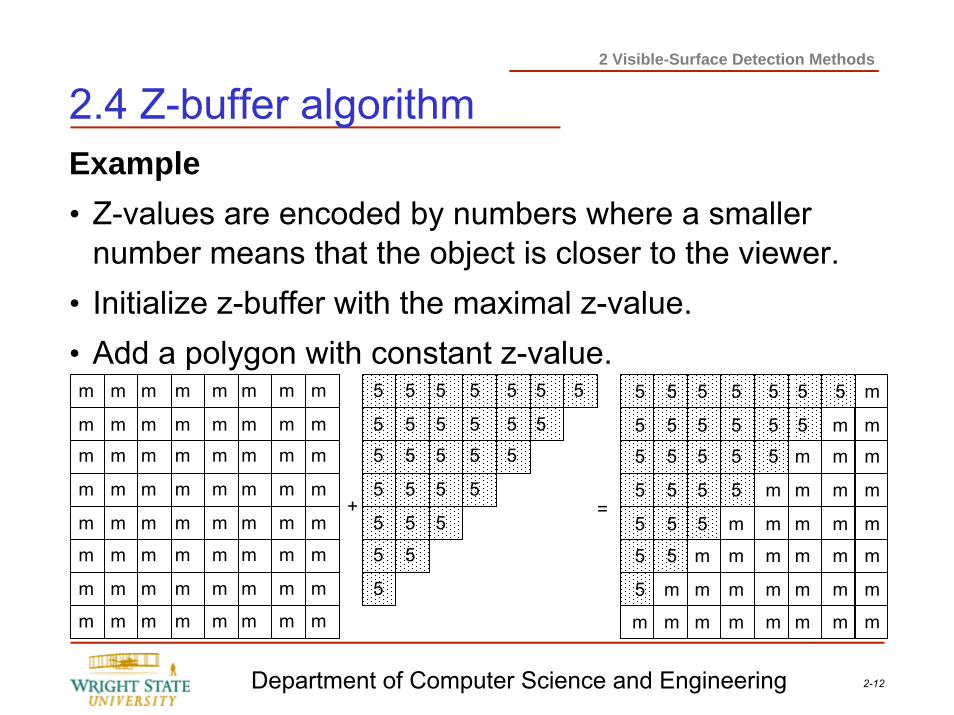
2.4 Z-buffer algorithmExample• Z-values are encoded by numbers where a smaller
number means that the object is closer to the viewer.• Initialize z-buffer with the maximal z-value.• Add a polygon with constant z-value.m
m
m
m
m
m
m
m
m
m
m
m
m
m
m
m
m
m
m
m
m
m
m
m
m
m
m
m
m
m
m
m
m
m
m
m
m
m
m
m
m
m
m
m
m
m
m
m
m
m
m
m
m
m
m
m
m
m
m
m
m
m
m
m
5
5
5
5
5
5
5
m
5
5
5
5
5
5
m
m
5
5
5
5
5
m
m
m
5
5
5
5
m
m
m
m
5
5
5
m
m
m
m
m
5
5
m
m
m
m
m
m
5
m
m
m
m
m
m
m
m
m
m
m
m
m
m
m
5
5
5
5
5
5
5
5
5
5
5
5
5
5
5
5
5
5
5
5
5
5
5
5
5
5
5
5
+ =
2-13Department of Computer Science and Engineering
2 Visible-Surface Detection Methods
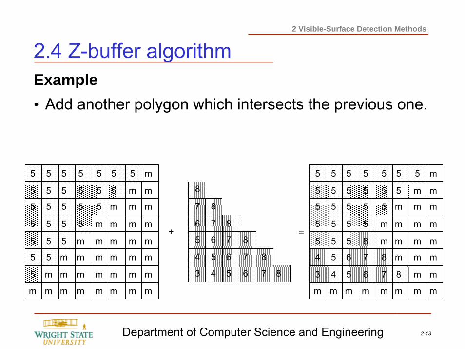
2.4 Z-buffer algorithmExample• Add another polygon which intersects the previous one.
5
5
5
5
5
5
5
m
5
5
5
5
5
5
m
m
5
5
5
5
5
m
m
m
5
5
5
5
m
m
m
m
5
5
5
m
m
m
m
m
5
5
m
m
m
m
m
m
5
m
m
m
m
m
m
m
m
m
m
m
m
m
m
m
5
5
5
5
5
4
3
m
5
5
5
5
5
5
4
m
5
5
5
5
5
6
5
m
5
5
5
5
8
7
6
m
5
5
5
m
m
8
7
m
5
5
m
m
m
m
8
m
5
m
m
m
m
m
m
m
m
m
m
m
m
m
m
m
8
7
6
5
4
3
8
7
6
5
4
8
7
6
5
8
7
6
8
7 8
+ =
2-14Department of Computer Science and Engineering
2 Visible-Surface Detection Methods
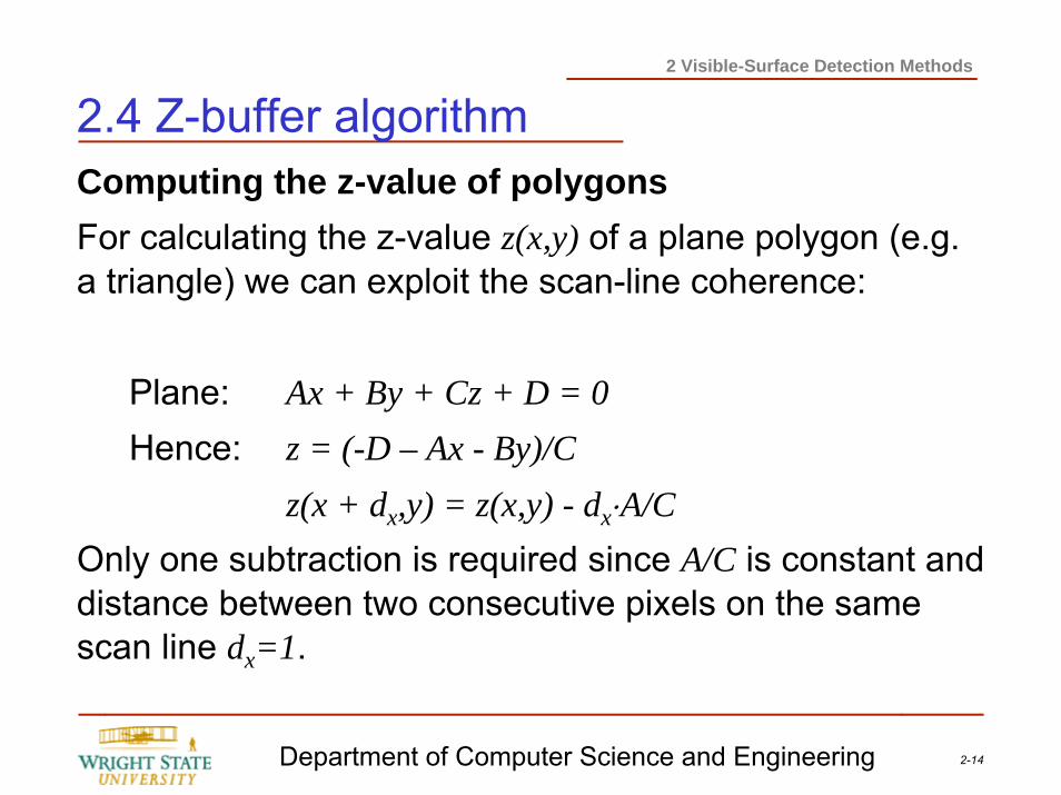
2.4 Z-buffer algorithmComputing the z-value of polygonsFor calculating the z-value z(x,y) of a plane polygon (e.g. a triangle) we can exploit the scan-line coherence:
Plane: Ax + By + Cz + D = 0Hence: z = (-D – Ax - By)/C
z(x + dx,y) = z(x,y) - dx⋅A/COnly one subtraction is required since A/C is constant and distance between two consecutive pixels on the same scan line dx=1.
2-15Department of Computer Science and Engineering
2 Visible-Surface Detection Methods
2.4 Z-buffer algorithmAdvantages+ Algorithm is simple to implement (especially in
hardware).+ Independent of the representation of the objects of the
scene; the only requirement is that it needs to be possible to compute the z-value for every point of the object’s surface.
+ No limitation regarding complexity of the scene.+ No special order or sorting of the objects necessary
2-16Department of Computer Science and Engineering
2 Visible-Surface Detection Methods
2.4 Z-buffer algorithmDisadvantages– Resolution of the z-buffer determines the discretization
of the image depth, e.g. when using 20 bits 220 different depth values are possible; hence, scenes with great distances between objects and high detailed objects are problematic.
– Requires additional memory – memory requirement can be reduced by sub-division of the image and processing each sub-image individually.
– Transparency (alpha-buffering) and anti-aliasing can only be integrated by costly modifications.
2-17Department of Computer Science and Engineering
2 Visible-Surface Detection Methods
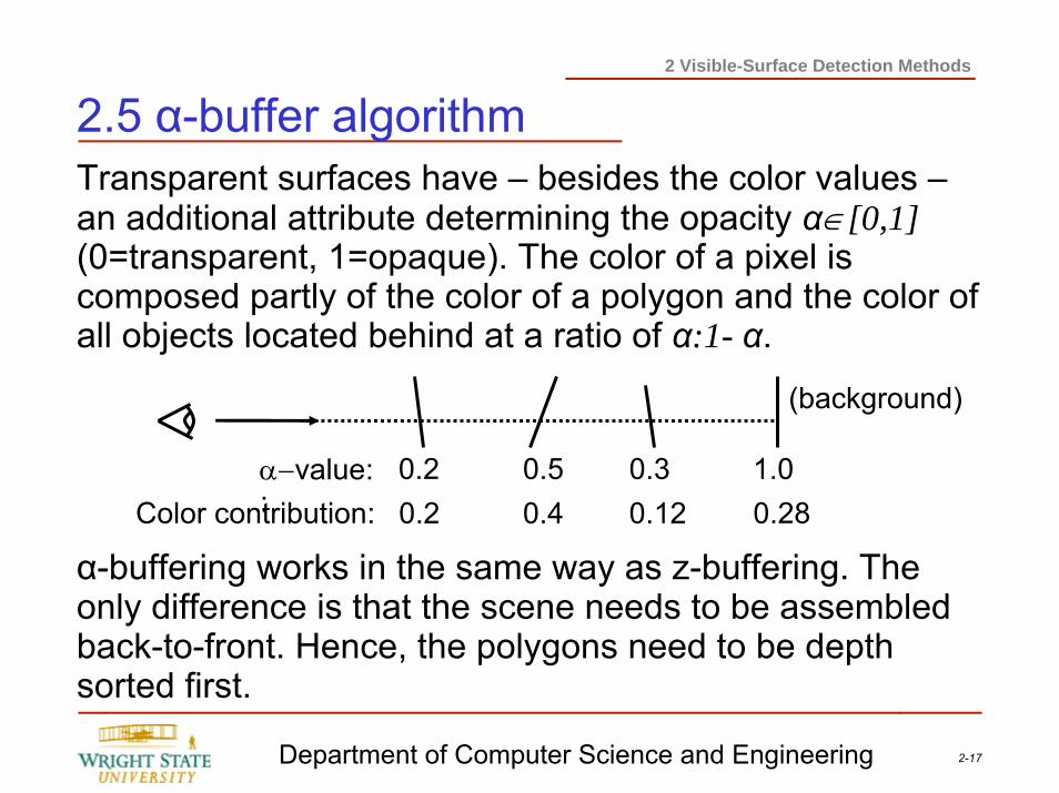
2.5 α-buffer algorithmTransparent surfaces have – besides the color values –an additional attribute determining the opacity α∈[0,1](0=transparent, 1=opaque). The color of a pixel is composed partly of the color of a polygon and the color of all objects located behind at a ratio of α:1- α.
α-buffering works in the same way as z-buffering. The only difference is that the scene needs to be assembled back-to-front. Hence, the polygons need to be depth sorted first.
α−value: :Color contribution:
0.2 0.5 0.3
(background)
0.2 0.4 0.121.00.28
2-18Department of Computer Science and Engineering
2 Visible-Surface Detection Methods
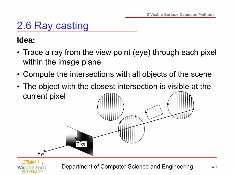
2.6 Ray castingIdea:• Trace a ray from the view point (eye) through each pixel
within the image plane• Compute the intersections with all objects of the scene• The object with the closest intersection is visible at the
current pixel
Eye
Pixel
2-19Department of Computer Science and Engineering
2 Visible-Surface Detection Methods
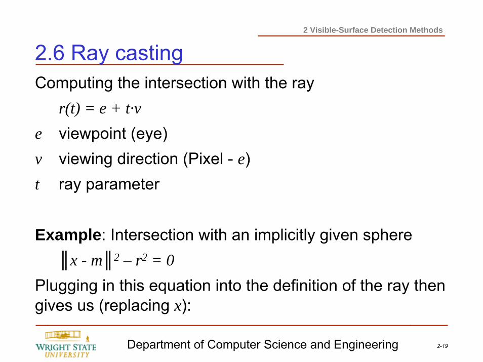
2.6 Ray castingComputing the intersection with the ray
r(t) = e + t·ve viewpoint (eye)v viewing direction (Pixel - e)t ray parameter
Example: Intersection with an implicitly given sphere║x - m║2 – r2 = 0
Plugging in this equation into the definition of the ray then gives us (replacing x):
2-20Department of Computer Science and Engineering
2 Visible-Surface Detection Methods
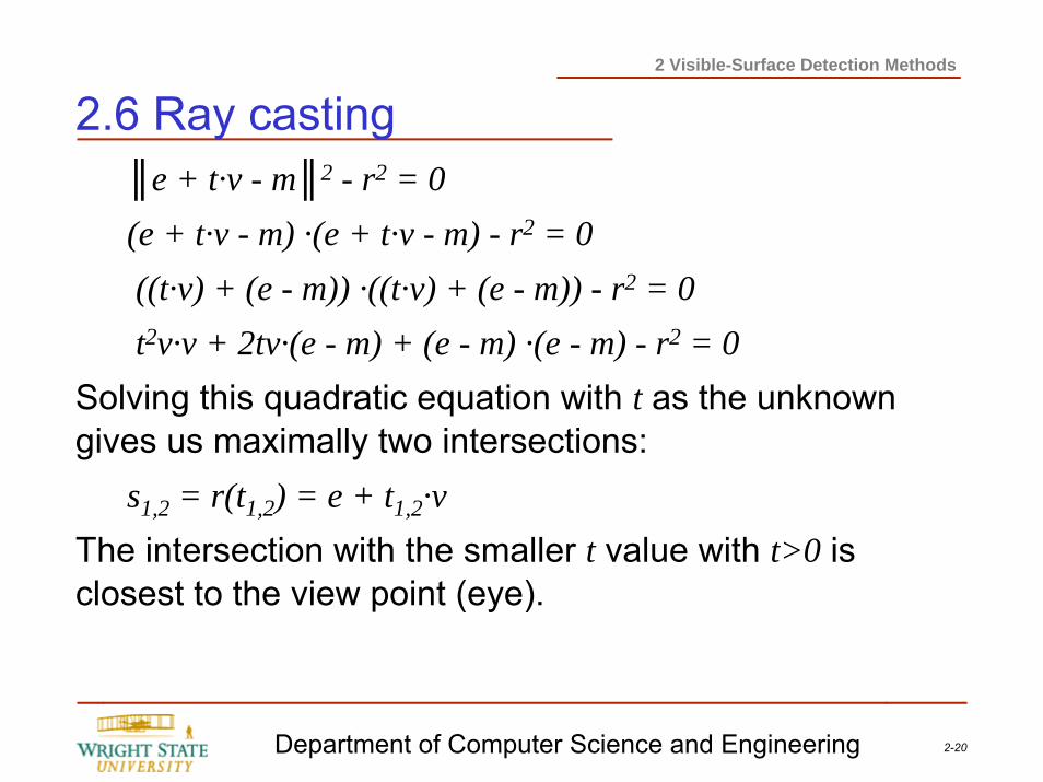
2.6 Ray casting║e + t·v - m║2 - r2 = 0(e + t·v - m) ·(e + t·v - m) - r2 = 0((t·v) + (e - m)) ·((t·v) + (e - m)) - r2 = 0t2v·v + 2tv·(e - m) + (e - m) ·(e - m) - r2 = 0
Solving this quadratic equation with t as the unknown gives us maximally two intersections:
s1,2 = r(t1,2) = e + t1,2·vThe intersection with the smaller t value with t>0 is closest to the view point (eye).
2-21Department of Computer Science and Engineering
2 Visible-Surface Detection Methods
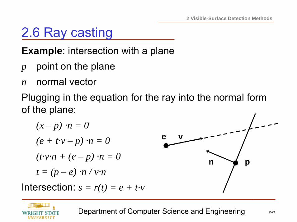
2.6 Ray castingExample: intersection with a planep point on the planen normal vectorPlugging in the equation for the ray into the normal form of the plane:
(x – p) ·n = 0(e + t·v – p) ·n = 0(t·v·n + (e – p) ·n = 0t = (p – e) ·n / v·n
Intersection: s = r(t) = e + t·v
e v
pn
2-22Department of Computer Science and Engineering
2 Visible-Surface Detection Methods
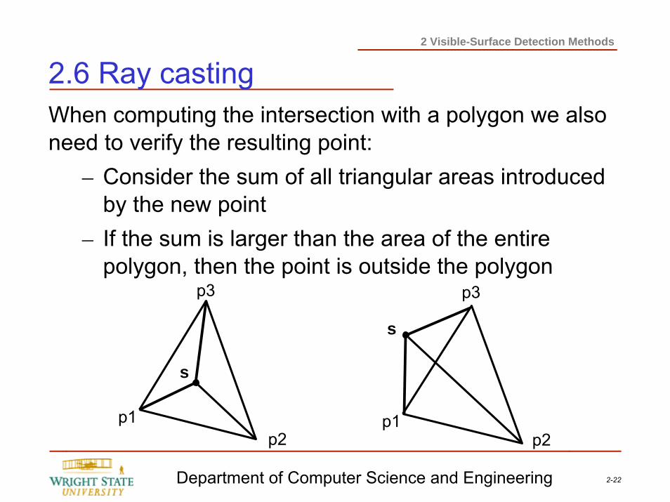
2.6 Ray castingWhen computing the intersection with a polygon we also need to verify the resulting point:
– Consider the sum of all triangular areas introduced by the new point
– If the sum is larger than the area of the entire polygon, then the point is outside the polygon
p1p2
p3
p2p1
p3
s
s
2-23Department of Computer Science and Engineering
2 Visible-Surface Detection Methods
2.6 Ray castingDisadvantages:• Fore every ray, the intersection with all objects need to
be computed. Depending on the complexity of the scene, this can mean a lot of computations.
• At a resolution of 1024×1024 and a scene with 100 objects about 100 million intersections need to be computed!
• With a typical scene, up to 95% of the computational effort is spent on computing the intersections.
2-24Department of Computer Science and Engineering
2 Visible-Surface Detection Methods
2.6 Ray castingSpeed-up approaches• Transformation of the rays onto the z-axis; if all objects
are transformed using the same transformation, then the intersection will always occur at x=y=0.
• Bounding box: for complex objects, a simple quad is computed that encloses the object; Then, if there is no intersection with the bounding box the ray will not intersect the enclosed objects either.
• Avoiding the computation of unnecessary intersections: hierarchies and space sub-division.
2-25Department of Computer Science and Engineering
2 Visible-Surface Detection Methods
2.6 Ray castingHierarchies• Tree-like data structures of bounding boxes
– Leafs: objects of the scene– Inner node: bounding box of objects with sub-trees
• If a ray does not intersect a bounding box of an inner node, all objects within this bounding box, i.e. the node’s sub-tree, does not need to be checked.
• Problem: it might be difficult to generate a suitable hierarchy.
2-26Department of Computer Science and Engineering
2 Visible-Surface Detection Methods
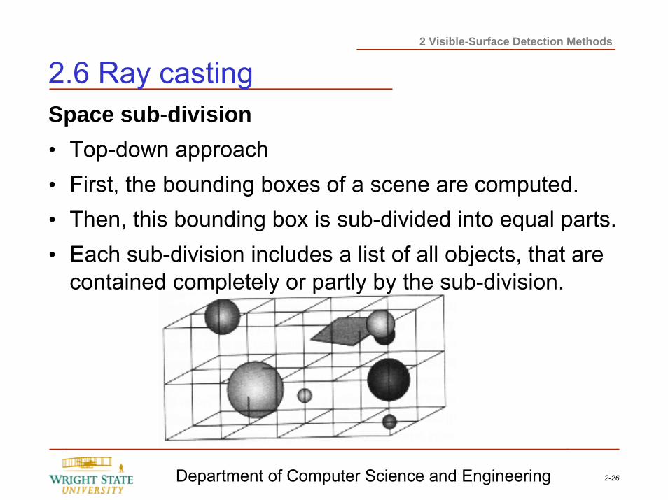
2.6 Ray castingSpace sub-division• Top-down approach• First, the bounding boxes of a scene are computed.• Then, this bounding box is sub-divided into equal parts.• Each sub-division includes a list of all objects, that are
contained completely or partly by the sub-division.
2-27Department of Computer Science and Engineering
2 Visible-Surface Detection Methods
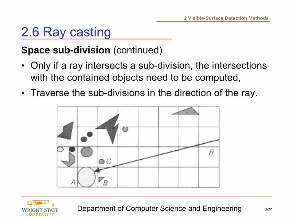
2.6 Ray castingSpace sub-division (continued)• Only if a ray intersects a sub-division, the intersections
with the contained objects need to be computed,• Traverse the sub-divisions in the direction of the ray.
2-28Department of Computer Science and Engineering
2 Visible-Surface Detection Methods
2.7 OpenGL Visibility Detection MethodsOpenGL implements two of the previously described visibility methods:
– Back-face culling– Depth-buffer (z-buffer,α-buffer)
The implemented depth-buffer works fine in case where there are only opaque objects. However, the problem with the depth-buffer is that it requires additional care if there are transparent objects within the scene. Transparent objects need to be depth-sorted manually!
2-29Department of Computer Science and Engineering
2 Visible-Surface Detection Methods
2.7 OpenGL Visibility Detection MethodsOpenGL back-face cullingTo enable OpenGL’s back-face culling you need to issue the command:
glEnable (GL_CULL_FACE);
glCullFace (mode);
The parameter mode can have the values GL_BACK(remove back-faces), GL_FRONT (remove front faces), or GL_FRONT_BACK (remove both front and back faces).
To disable back-face culling you can use the command:glDisable (GL_CULL_FACE);
2-30Department of Computer Science and Engineering
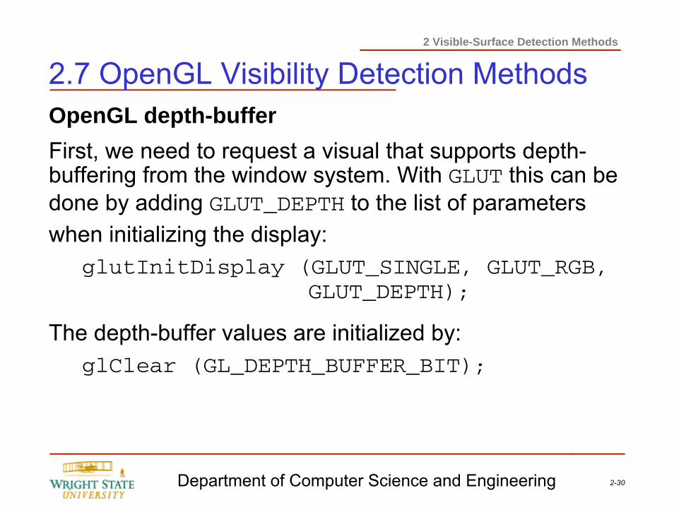
2 Visible-Surface Detection Methods
2.7 OpenGL Visibility Detection MethodsOpenGL depth-bufferFirst, we need to request a visual that supports depth-buffering from the window system. With GLUT this can be done by adding GLUT_DEPTH to the list of parameters when initializing the display:
glutInitDisplay (GLUT_SINGLE, GLUT_RGB, GLUT_DEPTH);
The depth-buffer values are initialized by:glClear (GL_DEPTH_BUFFER_BIT);
2-31Department of Computer Science and Engineering
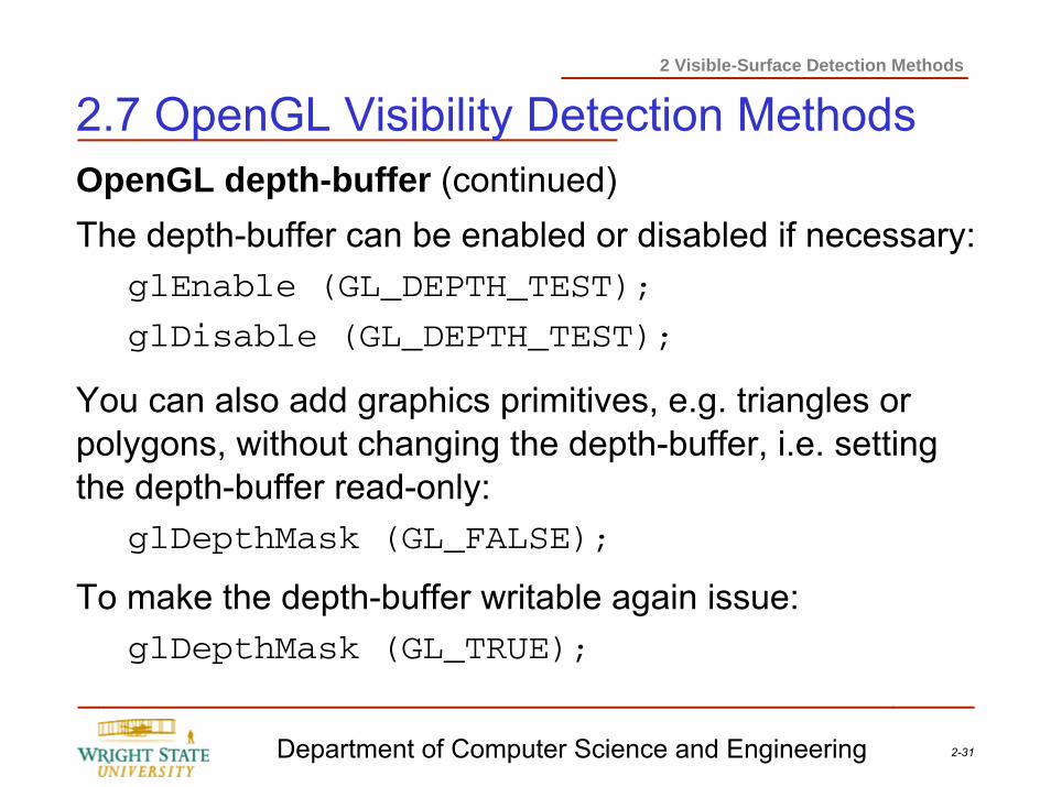
2 Visible-Surface Detection Methods
2.7 OpenGL Visibility Detection MethodsOpenGL depth-buffer (continued)The depth-buffer can be enabled or disabled if necessary:
glEnable (GL_DEPTH_TEST);
glDisable (GL_DEPTH_TEST);
You can also add graphics primitives, e.g. triangles or polygons, without changing the depth-buffer, i.e. setting the depth-buffer read-only:
glDepthMask (GL_FALSE);
To make the depth-buffer writable again issue:glDepthMask (GL_TRUE);
2-32Department of Computer Science and Engineering
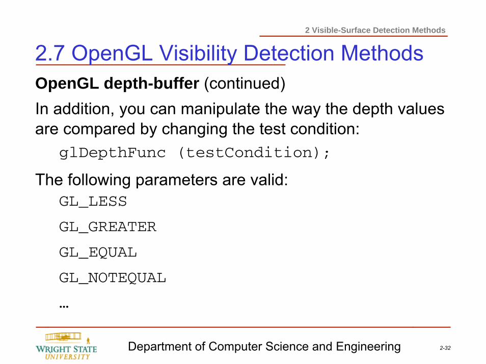
2 Visible-Surface Detection Methods
2.7 OpenGL Visibility Detection MethodsOpenGL depth-buffer (continued)In addition, you can manipulate the way the depth values are compared by changing the test condition:
glDepthFunc (testCondition);
The following parameters are valid:GL_LESS
GL_GREATER
GL_EQUAL
GL_NOTEQUAL
…
2-33Department of Computer Science and Engineering
2 Visible-Surface Detection Methods
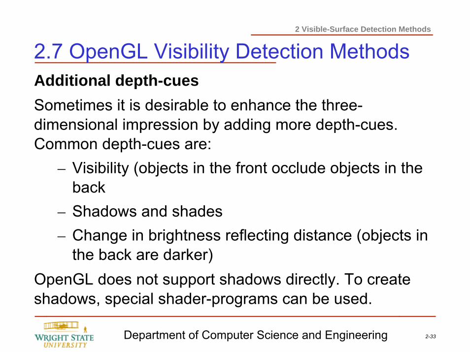
2.7 OpenGL Visibility Detection MethodsAdditional depth-cuesSometimes it is desirable to enhance the three-dimensional impression by adding more depth-cues. Common depth-cues are:
– Visibility (objects in the front occlude objects in the back
– Shadows and shades– Change in brightness reflecting distance (objects in
the back are darker)OpenGL does not support shadows directly. To create shadows, special shader-programs can be used.
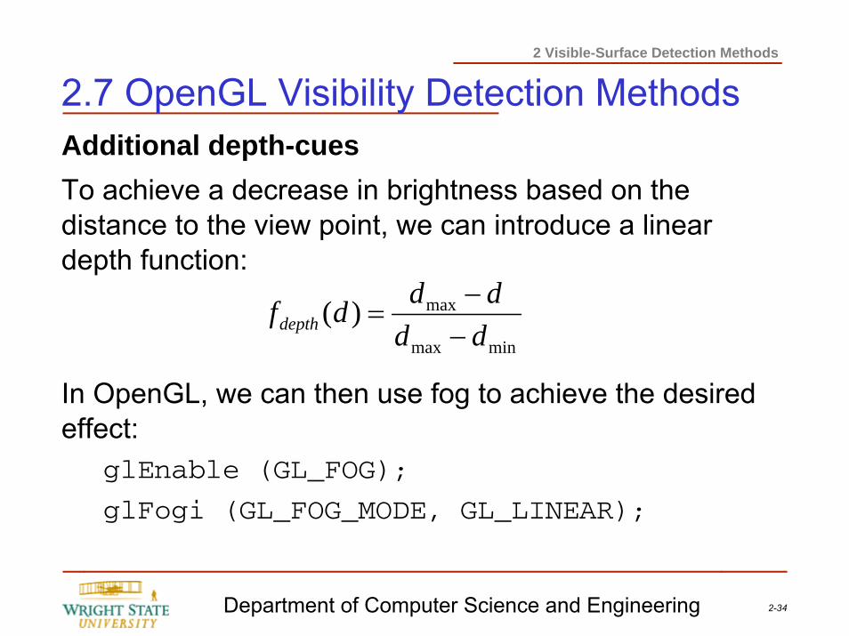
2-34Department of Computer Science and Engineering
2 Visible-Surface Detection Methods
2.7 OpenGL Visibility Detection MethodsAdditional depth-cuesTo achieve a decrease in brightness based on the distance to the view point, we can introduce a linear depth function:
In OpenGL, we can then use fog to achieve the desired effect:
glEnable (GL_FOG);
glFogi (GL_FOG_MODE, GL_LINEAR);
minmax
max)(dddddfdepth −
−=