(19) united states (12) patent application publication … · wcdma, etc.), and multi-carrier based...
TRANSCRIPT

(19) United States US 20080280631A1
(12) Patent Application Publication (10) Pub. No.: US 2008/0280631 A1 Lee et al. (43) Pub. Date: Nov. 13, 2008
(54) METHOD FOR PROCESSING PAGING INFORMATION IN A WIRELESS MOBILE COMMUNICATION SYSTEM
Young-Dae Lee, Gyeonggi-Do (KR); Sung-Duck Chun, Gyeonggi-Do (KR); Myung-Cheul Jung, Seoul (KR); Sung-Jun Park, Gyeonggi-Do (KR)
(76) Inventors:
Correspondence Address: LEE, HONG, DEGERMAN, SCHMADEKA 660 S. FIGUEROASTREET, Suite 2300 LOS ANGELES, CA 90017 (US)
KANG &
(21) Appl. No.: 12/092,056
(22) PCT Filed: Oct. 25, 2006
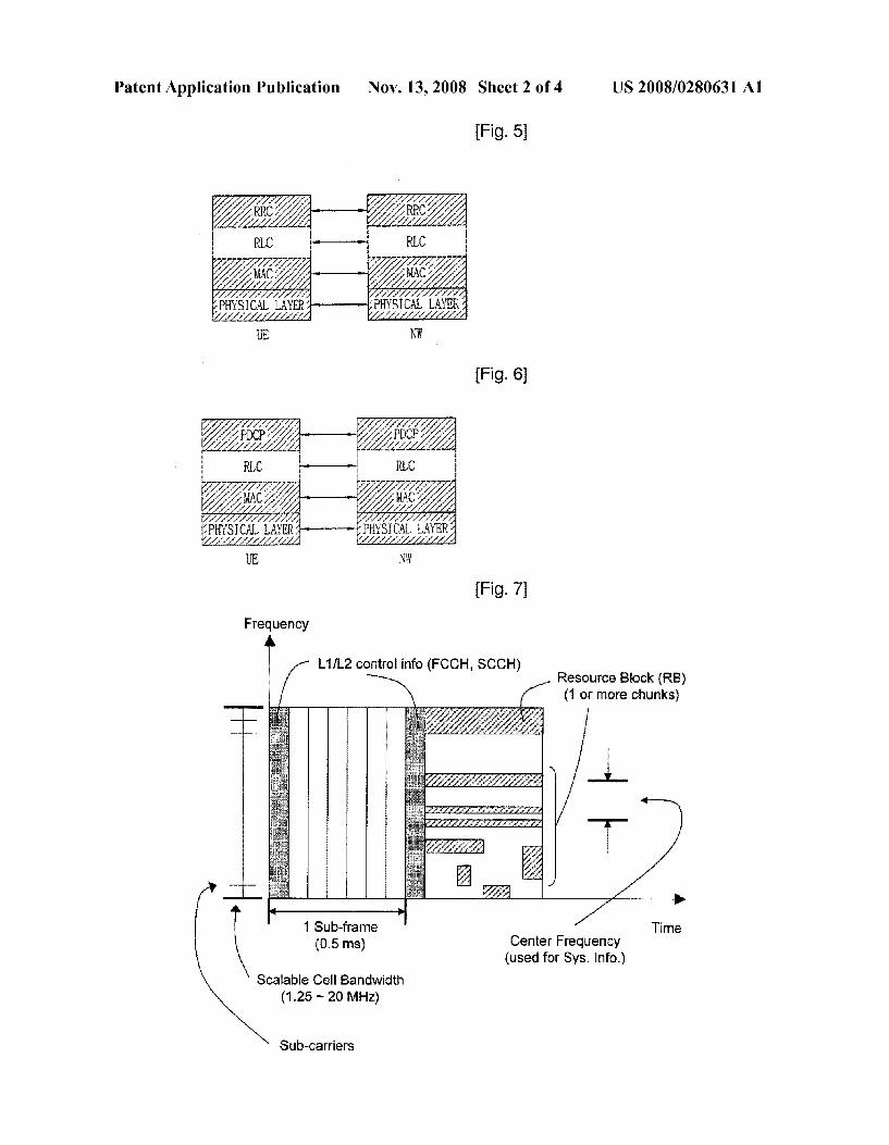
(86). PCT No.:
S371 (c)(1), (2), (4) Date:
PCT/KRO6/04371
Apr. 29, 2008
(30) Foreign Application Priority Data
Oct. 31, 2005 (KR) ........................ 10-2005-O103510
Publication Classification
(51) Int. Cl. H04O 7/20 (2006.01)
(52) U.S. Cl. ........................................................ 45S/458
(57) ABSTRACT
In a wireless mobile communications system, a method for processing paging information allows the operations of a mobile terminal to be simplified and permits efficient use of resources for the mobile terminal. The network instructs in advance, the transmission of control information, Such as a particular paging message, a notification message, System information and the like, via a single indicator channel. The mobile terminal receives this single indicator channel and uses the indicator information that was transmitted via the indicator channel in order to receive the control information.

Patent Application Publication Nov. 13, 2008 Sheet 1 of 4 US 2008/0280631 A1
(Fig. 1)
1 Frame (10 ms)
1 Sub-frame (0.5 ms)
Fig. 2)
1 Sub-frame (0.5 ms)
FREQUENCY DOMAIN
DR. DDDDDR3DDDDDRDE) DDD DDDDDDDDDDDDDDDDDDD E. EEE DDDDDDDDDDDD EE DDDDDDDDDDDDDDDD DDDDEREDDDDDR3DDDDREDD
DDDDDDDDDDD IEEE EEEEEEEEEEEEEEEEEE ER3: FIRST REFERENCE SYMBOL m R.: SECOND REFERENCE SYMBOL
| D: DATA
0.5ms
Patent Application Publication Nov. 13, 2008 Sheet 2 of 4 US 2008/0280631 A1
Fig. 5)
RRC RRC 2 2
Fig. 6)
2%. 23% RLC - RLC
(Fig. 7) Frequency A
L1/L2 control info (FCCH, SCCH) Resource Block (RB) (1 or more chunks)
1 Sub-frame (0.5 ms) Center Frequency
(used for Sys. Info.)
Time
Scalable Cell Bandwidth (1.25 - 20 MHz)
Sub-carriers

US 2008/0280631 A1 Nov. 13, 2008 Sheet 3 of 4 Patent Application Publication
Fig. 8)
CNE SUB RAME
FREQUENCY
(Fig.9)
REQUENCY
ONE SUBFRAME
(Fig. 10)
(Fig.11
SYSE BANDIDT
FREQUENCY

Patent Application Publication Nov. 13, 2008 Sheet 4 of 4 US 2008/0280631 A1
(Fig. 12)
FREQUENCY
%56%56 is 2. %5, ÉE3 C-3 3 ACTIVE MODE 3.23% (i22
FCCH

US 2008/0280631 A1
METHOD FOR PROCESSING PAGING INFORMATION IN A WIRELESS MOBILE
COMMUNICATION SYSTEM
TECHNICAL FIELD
0001. The present invention relates to wireless (radio) mobile communication systems, and in particular, relates to a method for processing paging information allows the opera tions of a mobile terminal to be simplified and permits effi cient use of resources for the mobile terminal.
BACKGROUND ART
0002 To support broadband wireless (e.g., WiMAX) access, there are different types of broadband wireless air interfaces, such as cellular 3G technologies (e.g., UMTS, WCDMA, etc.), and multi-carrier based multiple access tech niques (e.g., OFDMA, OFDM-TDMA, OFDM-CDMA, etc.). Frequency division multiplexing involves Sub-channel ization, of which at least four types (OFDM, Flash OFDM, sOFDMA and OFDMA) exist. 0003 Orthogonal Frequency Division Multiplexing (OFDM) involves the splitting of a radio signal into multiple Smaller Sub-signals that are then transmitted simultaneously at different frequencies to a receiver. OFDM refers to a form of multi-carrier transmission where all the sub-carriers are orthogonal to each other. Certain IEEE standards and 3GPP standards are related to various aspects of OFDM. 0004 FIGS. 1 and 2 show a typical frame that is used in OFDM. One frame has a time duration of 10 ms (millisec onds) and consists of 20 Sub-frames, each having a time duration of 0.5 ms. Each sub-frame may consist of a resource block (RB) that contains data or information, and a cyclic prefix (CP) that is a guard interval needed for conventional OFDM modulation (but not needed for OFDM with pulse shaping, i.e., OFDM/OQAM). The sub-frame duration cor responds to the minimum downlink TTI (Transmission Time Interval). 0005 FIG. 3 shows a basic downlink reference-signal structure consisting of known reference symbols. Namely, a mapping of physical channel symbols infrequency domain is shown. In other words, channel-coded, interleaved, and data modulated information (i.e., Layer 3 information) is mapped onto OFDM time/frequency symbols. The OFDM symbols can be organized into a number (M) of consecutive Sub carriers for a number (N) of consecutive OFDM symbols. 0006. Here, it is assumed that 7 OFDM symbols exist per sub-frame (when the CP length is short). In case of a long CP or a different frame structure, this basic downlink reference signal structure would be slightly different. 0007 Reference symbols (i.e., first reference symbols) are located in the first OFDM symbol of every sub-frame assigned for downlink transmission. This is valid for both FDD and TDD, as well as for both long and short CP. Addi tional reference symbols (i.e., second reference symbols) are located in the third last OFDM symbol of every sub-frame assigned for downlink transmission. This is the baseline for both FDD and TDD, as well as for both long and short CP. However, for FDD, an evaluation of whether the second ref erence symbols are need should be made. 0008 FIG. 4 shows an exemplary structure of an Evolved Universal Mobile Telecommunications System (E-UMTS). The E-UMTS system is a system that has evolved from the
Nov. 13, 2008
UMTS system, and its standardization work is currently being performed by the 3GPP standards organization. 0009. The E-UMTS network generally comprises at least one mobile terminal (i.e., user equipment: UE), base stations (i.e., Node Bs), a control plane server (CPS) that performs radio (wireless) control functions, a radio resource manage ment (RRM) entity that performs radio resource management functions, a mobility management entity (MME) that per forms mobility management functions for a mobile terminal, and an access gateway (AG) that is located at an end of the E-UMTS network and connects with one or more external networks. Here, it can be understood that the particular names of the various network entities are not limited to those men tioned above.
0010. The various layers of the radio interface protocol between the mobile terminal and the network may be divided into L1 (Layer 1), L2 (Layer 2), and L3 (Layer 3) based upon the lower three layers of the Open System Interconnection (OSI) standard model that is known the field of communica tion systems. Among these layers, a physical layer that is part of Layer 1 provides an information transfer service using a physical channel, while a Radio Resource Control (RRC) layer located in Layer 3 performs the function of controlling radio resources between the mobile terminal and the network. To do so, the RRC layer exchanges RRC messages between the mobile terminal and the network. The functions of the RRC layer may be distributed among and performed within the Node B, the CPS/RRM and/or the MME. 0011 FIGS. 5 and 6 show an exemplary architecture of the radio interface protocol between the mobile terminal and the UTRAN (UMTS Terrestrial Radio Access Network). The radio interface protocol of FIGS. 5 and 6 is horizontally comprised of a physical layer, a data link layer, and a network layer, and vertically comprised of a user plane for transmit ting user data and a control plane for transferring control signaling. The radio interface protocol layer of FIGS. 5 and 6 may be divided into L1 (Layer 1), L2(Layer 2), and L3 (Layer 3) based upon the lower three layers of the Open System Interconnection (OSI) standards model that is known the field of communication systems. 0012 Particular layers of the radio protocol control plane of FIG.5 and of the radio protocol user plane of FIG. 6 will be described below. The physical layer (i.e., Layer 1) uses a physical channel to provide an information transfer service to a higher layer. 0013 The physical layer is connected with a medium access control (MAC) layer located thereabove via a transport channel, and data is transferred between the physical layer and the MAC layer via the transport channel. Also, between respectively different physical layers, namely, between the respective physical layers of the transmitting side (transmit ter) and the receiving side (receiver), data is transferred via a physical channel. 0014. The MAC layer of Layer 2 provides services to a radio link control (RLC) layer (which is a higher layer) via a logical channel. The RLC layer of Layer 2 supports the trans mission of data with reliability. It should be noted that the RLC layer in FIGS. 5 and 6 is depicted in dotted lines, because if the RLC functions are implemented in and per formed by the MAC layer, the RLC layer itself may not need to exist. The PDCP layer of Layer 2 performs a header com pression function that reduces unnecessary control informa tion Such that data being transmitted by employing Internet

US 2008/0280631 A1
protocol (IP) packets, such as IPv4 or IPv6, can be efficiently sent over a radio (wireless) interface that has a relatively small bandwidth.
0015 The radio resource control (RRC) layer located at the lowermost portion of Layer 3 is only defined in the control plane, and handles the control of logical channels, transport channels, and physical channels with respect to the configu ration, re-configuration and release of radio bearers (RB). Here, the RB refers to a service that is provided by Layer 2 for data transfer between the mobile terminal and the UTRAN.
0016. As for channels used in downlink transmission for transmitting data from the network to the mobile terminal, there is a broadcast channel (BCH) used for transmitting system information, and a shared channel (SCH) used for transmitting user traffic or control messages. As for channels used in uplink transmission for transmitting data from the mobile terminal to the network, there is a random access channel (RACH) used for transmitting an initial control mes sage, and a shared channel (SCH) used for transmitting user traffic or control messages. 0017. One function implemented in 3GPP systems is a paging procedure. The paging procedure is necessary for converting the UE from idle mode into active mode. This procedure is implemented via a paging control channel (PCCH), a paging channel (PCH), a secondary common con trol physical channel (S-CCPCH), and a paging indicator channel (PICH). The paging procedure utilizes two different types of data (or signals), namely, a paging indicator (PI) and Substantive paging data. The PI is sent on a paging indicator channel (PICH) in advance of the Substantive paging data. The Substantive paging data is sent on a separate paging channel (PCH), which is transported by a Secondary Com mon Control Physical Channel (SCCPCH).
DISCLOSURE OF INVENTION
Technical Problem
0018. Before sending data to a particular mobile terminal, the network transmits a paging message on the downlink in order to determine the particular cell that the UE is located in. In the related art paging message transmitting method, an indicator (which informs in advance that a paging message will be transmitted) is transmitted through a separate (dis tinct) channel. Such as a paging indicator channel. Addition ally, an indicator (which informs in advance that a notification message for a multicast and broadcast service will be trans mitted) is also transmitted through a separate (distinct) chan nel. In addition to these channels, the mobile terminal must also receive other channels, such as a broadcast channel used to periodically transmit system information. As there are a large total number of channels that a mobile terminal should receive due to transmissions through separate (distinct) chan nels according to each type of purpose, problems related to more complicated mobile terminal operations and a waste of mobile terminal resources occur.
Technical Solution
0019. The present invention has been developed in order to solve the above described problems of the related art. As a result, the present invention provides a method for processing
Nov. 13, 2008
paging information Such that the operations of a mobile ter minal can be simplified and permits efficient use of resources for the mobile terminal.
BRIEF DESCRIPTION OF THE DRAWINGS
0020 FIG. 1 shows an exemplary structure of one frame used in OFDM. 0021 FIG. 2 shows an exemplary structure of one sub frame within the frame of FIG. 1. 0022 FIG.3 shows an example of how data and reference symbols for OFDM may be expressed in the frequency domain and the time domain. 0023 FIG. 4 shows an overview of a E-UMTS network architecture. 0024 FIGS. 5 and 6 show an exemplary structure (archi tecture) of a radio interface protocol between a mobile termi nal and a UTRAN according to the 3GPP radio access net work Standard. 0025 FIG. 7 is a diagram to explain the features of the present invention by showing where the control information and resource blocks may be located within each sub-frame with respect to frequency and time. 0026 FIG. 8 is a diagram used to explain a control infor mation transmission and reception method according to an exemplary embodiment of the present invention. 0027 FIG. 9 is a diagram used to explain a control infor mation transmission and reception method according to another exemplary embodiment of the present invention. 0028 FIG. 10 is a diagram used to explain a control infor mation transmission and reception method according to another exemplary embodiment of the present invention. 0029 FIG. 11 is a diagram used to explain a control infor mation transmission and reception method according to another exemplary embodiment of the present invention. 0030 FIG. 12 is a diagram used to explain constituting information of an FCCH according to an exemplary embodi ment of the present invention.
MODE FOR THE INVENTION
0031 One aspect of the present invention is the recogni tion by the present inventors regarding the problems and drawbacks of the related art described above and explained in more detail hereafter. Based upon Such recognition, the fea tures of the present invention have been developed. 0032. In the related art, it can be said that the system information is always fixed or non-flexible. Such fixed format allows a mobile terminal to easily detect and properly read the system information transmitted from the network. 0033. In contrast, the features of the present invention allow at least Some portions of the system information to be dynamically (or flexibly) changed. Appropriate indicators are included such that a mobile terminal can properly detect and read the dynamic (flexible) system information. As a result, further system information may be added as desired in order to Support technical evolution and advancements, which thus allows for future enhancements or continued expansion of currently used system information. 0034. It should be noted that the features of the present invention are related to issues regarding the long-term evolu tion (LTE) of the 3GPP standard. As such, the 3GPP TS 25.813 (LTE TR) and its related sections or portions thereof, as well as various developing enhancements thereofpertainto the present invention. Such enhancements and evolution have

US 2008/0280631 A1
resulted in the use of a particular prefix (the letter E) when labeling various network entities (e.g., eNode B), protocol layers, channels, and the like. However, it can be clearly understood that Such labeling and other terminology are merely exemplary and thus may be altered (or later clarified) as a result of ongoing or future discussions. 0035 First, with respect to the features of the present invention, certain aspects regarding the paging procedure will be explained below. 0036. In idle mode, the UE needs to complete a periodical Supervision procedure in order to monitor the paging channel. Upon receiving paging information related to the UE itself, the UE then changes into active mode and receives paging from the network. The monitoring in the periodical supervi sion procedure is realized through the monitoring of a paging indicator (PI). The paging indicator is sent once via paging indicator channel (PICH) in every cycle. 0037. When the RRC layer of the UE and the RRC layer of the UTRAN are connected to transmit and receive an RRC message between one another, the UE is considered to be in an RRC connected state. When they are not connected, the UE is considered to be in an idle state.
0038. When in the RRC-connected state, the UE can be divided into a URA PCH state, a CELL PCH state, a CELL FACH state, and/or a CELL DCH state. In particular, when the UE is in idle state (in addition to the URA PCH state and the CELL PCH state), it wakes up only at each discontinuous reception (DRX) cycle to receive a PICH (Paging Indicator Channel) transmitting paging information, in order to reduce power consumption. 0039. When in URA PCH state or CELL PCH state, the UE receives and stores a UTRAN specific DRX cycle length, and discontinuously receives the PICH according to the UTRAN specific DRX cycle length. 0040. In addition, in idle state, the UE receives and stores a CN domain specific DRX cycle length, and discontinuously receives the PICH according to the CN domain specific DRX cycle length. 0041. The UEfurther obtains and uses a DRX cycle length corresponding to its state through system information broad cast by the RRC layer of the UTRAN. 0042. The PICH is a physical channel used for transmit ting a Paging Indicator (PI), and has a fixed data rate of SF 256. The PICH is always used in association with an S-CCPCH (Secondary Common Control Physical Channel) to which the PCH (Paging Channel) is mapped. 0043. The UTRAN periodically transmits information including the PI through the PICH to the UE. The UE then periodically checks whether the PICH has a PI related to it. More specifically, the UE in idle state periodically wakes up to check the PICH. If a PI is received through the PICH, the UE receives the S-CCPCH to which the PCH is mapped, to thereby receive corresponding paging information. 0044) The UTRAN periodically transmits system infor mation through a BCH (Broadcast Channel) to the UE. More specifically, the UTRAN transmits an SIB (System Informa tion Block) which is a group of information for constituting a channel and a protocol, using the BCH and transmits infor mation for updating each type of system information to the UE based on the radio environment, which may undergo constant changes. 0045 FIG. 7 is a diagram to explain the features of the present invention by showing where the control information
Nov. 13, 2008
and resource blocks may be located within each sub-frame with respect to frequency and time. 0046. The structure (format) of a sub-frame in relation to the frequency domain and the time domain can be understood from FIG. 7. Namely, a single sub-frame has a time duration of 0.5 ms with 7 OFDM symbols (portions) therein. 0047. In the first portion of the sub-frame, control infor mation (i.e., L1/L2 control information, FCCH, SCCH, etc.) is included, while resource blocks (RBs) that may be in the form of one or more chunks may be located in the remaining portion of the Sub-frame. Here, a resource block may occupy the entire time duration of the sub-frame (excluding the time duration for the control information) or some partial time duration thereof. Also, each resource block (RB) may use a particular frequency range (i.e., a particular number of Sub carriers). 0048. The frequency axis can be referred to as a scalable cell bandwidth, which typically has a frequency range of 1.25-20 MHz. A plurality of sub-carriers exists in the scalable cell bandwidth. Of this frequency range, a so-called center frequency (of approximately 10 MHz) is mainly used in trans mitting system information. 0049. In the related art, such system information is con sidered to be fixed. Although this allows the terminal to easily read the system information, addition of new system infor mation is not possible. In contrast, the present invention allows for at least part of the system information to be flexible (or dynamic). 0050. To do so, the present invention divides (or separates or distinguishes) the system information into primary system information (e.g., Master Information Block: MIB) and non primary (or secondary) system information (e.g., System Information Block: SIB). 0051. The MIB is transmitted in a static manner (e.g., via a BCH for fixed manner transmission), while the SIB is trans mitted in a dynamic manner (e.g., via a downlink SCH for dynamic manner transmission). Here, transmission in a dynamic manner means that different frequency ranges and time durations can be used. 0.052 For each frame, the MIB contains information about where each SIB is located. Namely, the particular frequency range (i.e., Sub-carriers) and particular time duration (i.e., symbols) for each SIB is specified to allow the terminal (UE) to properly read the appropriate SIBs. For example, the MIB may indicate that a particular UE (e.g., UE #11) should read a particular resource block (e.g., RB #3). Here, the RB #3 can also be expressed as the information located at certain Sub carriers and certain symbols (e.g., at sub-carriers #13-60 and symbols #3-5). 0053. In a similar manner, for each sub-frame within one frame, the control information (located in the first portion) contains information about where each resource block (RB) is located. Namely, the frequency range and particular time duration for each RB is specified to allow the terminal (UE) to properly read the appropriate RBs. 0054 The above concepts generally depicted in FIG. 7 will be explained in more detail in the following description with reference to FIGS. 8 through 12. 0055 FIG. 8 is a diagram used to explain a control infor mation transmission and reception method according to an exemplary embodiment of the present invention. The network transmits a frame control channel (FCCH) at every particular period (i.e., a first period). Hereafter, the particular period is referred to as a frame.

US 2008/0280631 A1
0056. It should be noted that the FCCH may also be described in different terms. Namely, the control information transmitted by the network may be called L1/L2 control infor mation, FCCH, SCCH, or the like. Hereafter, such control information will mostly be referred to as FCCH, merely for the sake of explanation (although control information and SCCH are also described). 0057. As shown in FIG. 8, a MIB (Master Information Block) is repetitively transmitted at every second period, which is different that the above-mentioned first period. The MIB includes scheduling information for a SIB (System Information Block) that transmits system information, apag ing message, and a notification message. Namely, the MIB provides scheduling information related to which frequency and what time is used to transmit each type of control infor mation, Such as multiple SIBs, multiple paging messages, multiple notification messages, and the like. The second period may set to be greater than the first period. The MIB may be transmitted in the first frame of the period in which the MIB is to be transmitted. 0058. Here, the FCCH that is transmitted in each frame can inform about whether the data transmitted in the corre sponding time duration (frame) is a common control mes sage, a control message dedicated for a particular mobile terminal, common data, or data dedicated for a particular mobile terminal. Also, the FCCH informs about which fre quency and what time within the frame that a control message or data of the control information is transmitted.
0059. The mobile terminal periodically receives the FCCH at every first period. If the FCCH of a particular frame indicates the transmission of a MIB, the mobile terminal receives the MIB at the corresponding frequency and time in accordance with the scheduling information included in the indicator information transmitted through the FCCH. By referring to the MIB, the mobile terminal can obtain sched uling information for particular paging messages, particular notification messages, particular indicator messages, and the like. Through Such scheduling information, the mobile termi nal can determine which frequency and what time was used to transmit a particular SIB, a particular paging message, a particular notification message or the like. According to Such scheduling information, the mobile terminal can receive a notification message with respect to the SIB, the paging mes sage, and the Subscribed service that is should receive. 0060. The MIB may include eithera mobile terminal iden
tifier or a service identifier, or may include an indicator that indicates such an identifier. 0061 FIG. 9 is a diagram used to explain a control infor mation transmission and reception method according to another exemplary embodiment of the present invention. Referring to FIG. 9, the network periodically transmits a PN-MAP (i.e., a Paging and Notification MAP) that informs about indicator information for a paging message or a notifi cation message, and about Scheduling information. Here, the PN-MAP may be labeled differently. Namely, the PN-MAP is merely one type of L1/L2 control information that may be transmitted by the network. In fact, an MIB may be used instead of the PN-MAP in order to provide information about paging or notification messages and about scheduling. 0062 Also, it can be understood that paging is provided on a per UE (terminal) basis, while notification is provided on a per service basis. Thus, the concepts related to paging with respect to UEs, can be applied to notification with respect to services.
Nov. 13, 2008
0063. The PN-MAP may be transmitted during the first frame of a paging period or of a notification period. Here, the paging period and the notification period may be the same or may be different. The FCCH that is transmitted in each frame indicates whether the data transmitted in the corresponding time duration (frame) is a paging message, a notification message, or a PN-MAP. Also, the FCCH informs about the scheduling information that indicates which frequency and what time within the frame that each message or data of the control information is transmitted. 0064. The mobile terminal receives the PN-MAPat every paging period or at every notification period. Here, the mobile terminal can determine whether or not a corresponding frame contains a PN-MAP upon receiving the FCCH. Accordingly, the mobile terminal obtains the PN-MAP via the correspond ing frame only when the transmission of the PN-MAP is informed by the FCCH. 0065. By using the received PN-MAP, the mobile terminal obtains the scheduling information of a particular paging message or a particular notification message. The mobile terminal uses the scheduling information to determine which frequency and what time the particular paging message or the particular notification message was transmitted. The mobile terminal can receive its corresponding paging message according to the determined transmission information, and can receive a notification message with respect to the service it subscribed to. The PN-MAP may include either a mobile terminal identifier or a service identifier, or may include an indicator that indicates such an identifier. 0.066 FIG. 10 is a diagram used to explain a control infor mation transmission and reception method according to another exemplary embodiment of the present invention. Referring to FIG. 10, the network transmits a paging message or a notification message of multiple mobile terminals at every paging period. A paging message (for a particular mobile terminal), which is transmitted during one paging period, is transmitted through a particular frame that is mapped to an identifier of the mobile terminal. Also, a noti fication message (for a particular service), which is transmit ted during one notification period, may be transmitted through a particular frame that is mapped to an identifier of the service. Here, the paging period and the notification period may be the same or may be different. The FCCH that is transmitted in each frame indicates whether the data trans mitted in the corresponding time duration (frame) is a paging message or a notification message. Also, the FCCH informs about which frequency and what time within the frame that each message or data is transmitted. 0067. The mobile terminal periodically receives (accord ing to the paging period) a particular frame that is mapped to its identifier, in order to obtain a paging message for itself. Also, the mobile terminal periodically receives (according to the notification period) a particular frame that is mapped to an identifier of a service it wishes to receive, in order to obtain a notification message for the service. Here, before receiving the particular frame, the mobile terminal receives the FCCH of the corresponding frame, and only if the FCCH indicates the transmission of the paging message or the notification message, the paging message or the notification message is obtained via the frame.
0068 Accordingly, it can be said that the L1/L2 control information (i.e., system information, MIB, PN-MAP, etc.) serves the purpose of a PICH. Namely, a UE can monitor the L1/L2 control information to determine the location of a

US 2008/0280631 A1
particular resource block (RB) with respect to the time and frequency domains in order to obtain the necessary paging message. 0069 FIG. 11 is a diagram used to explain a control infor mation transmission and reception method according to another exemplary embodiment of the present invention. A cell that supports broadband frequencies with a bandwidth of 10 or 20 MHz, can provide a system bandwidth of narrow band frequencies for a mobile terminal operating in narrow band frequencies such as 1.25 MHz, 2.5 MHz, or the like. In this case, as shown in FIG. 11, a central bandwidth of the broadband frequencies is typically used for the system band width. Here, the MIB or PN-MAP, the paging messages, the notification messages, the SIBs, and the like should all be transmitted in the system bandwidth. However, SIBs that transmit particular system information may be transmitted outside of the system bandwidth. 0070. The FCCH (or other type of system information like L1/L2 control information, SCCH, etc.) transmitted in each frame indicates whether the data transmitted in the corre sponding time duration (frame) is a MIB or PN-MAP, a paging message, a notification message, an SIB, or the like. Also, the FCCH informs about which frequency and what time within the frame that each message or data is transmit ted. The FCCH may be transmitted upon being divided into an FCCH for system bandwidth and an FCCH for non-system bandwidth. Accordingly, a mobile terminal that only receives the system bandwidth may receive the FCCH for system bandwidth to obtain information of each data or message that is transmitted via the system bandwidth. Also, a mobile ter minal that receives the non-system bandwidth may receive the FCCH for non-system bandwidth to obtain information of each data or message that is transmitted via the non-system bandwidth. 0071. In other words, the concepts shown in FIG. 11 are for handling the situation for mobile terminals in idle mode. 0072 The network (system) supports the cell bandwidth of 20 MHz, while a mobile terminal typically can only sup port a 10 MHz bandwidth range. Thus, the L1/L2 control information needs to be transmitted in certain units (a fre quency range) such as, a range of 10 MHz, 5 MHz, or the like. As a result, there may be three scenarios for the frequency ranges used by the mobile terminal for reading data. Namely, of the 20 MHz scalable cell bandwidth, the mobile terminal may read one of three frequency ranges, i.e., the lower 10 MHz, the upper 10 MHz, or a middle (intermediate) 10 MHz thereof. 0.073 For mobile terminals in RRC connected mode, because the particular cell in which the connected mode mobile terminal is located is known, any one of the three 10 MHZ ranges and appropriate Switching among these three 10 MHz ranges is possible. However, for a mobile terminal in idle mode, because the particular cell in which the terminal is located cannot be known, only one of these three 10 MHz ranges can be used (typically, the intermediate 10 MHZ range is used). Meanwhile, the bandwidth outside the intermediate 10 MHZ range can be used for transmitting and receiving resource blocks for mobile terminals in connected mode. 0074. Here, although the above exemplary embodiment with reference to FIG. 11 is described for 10 MHz ranges, it is contemplated that the 20 MHz scalable cell bandwidth could also be divided up into 5 MHz units. 0075 FIG. 12 is a diagram used to explain constituting information of control information (i.e., an FCCH) according
Nov. 13, 2008
to an exemplary embodiment of the present invention. The FCCH provides to the mobile terminal, various types of con trol information related to data and control messages trans mitted during the corresponding period (i.e., during the cor responding frame). Here, the FCCH is shown to be comprised of five different FCCH portions. However, this is merely exemplary, and the number of FCCH portions may vary accordingly. (0076 Referring to FIG. 12, the first FCCH portion is a FCCH MAP that informs about the frequency and time of the FCCH transmission, a length of the FCCH information, radio resource parameters needed for receiving the FCCH informa tion, and the like. Such FCCH MAP may be always included in each frame. In the present invention, each frame may include all types of FCCH or may include only portions thereof. The FCCH MAP may inform about whether or not the remaining four types of FCCH portions (excluding the FCCH MAP) are transmitted in the corresponding frame. (0077. The second FCCH portion is a FCCH Idle Mode (DL) that includes control information needed on order to receive downlink control information when the mobile termi nal is in idle mode. This second FCCH portion may be included in a corresponding frame when control information to be transmitted on the downlink exists in the frame. The control information related to common control messages Such as the MIB, SIB, paging message, notification message, PN-MAP, etc. may be included in this second FCCH portion. Also, the MIB, SIB, paging message, notification message, PN-MAP, etc. may be included in this second FCCH portion. (0078. The third FCCH portion is a FCCH Idle Mode (UL) that includes control information needed in order to transmit uplink control information when the mobile terminal is in idle mode. This third FCCH portion may include information that is needed for uplink random access transmissions. When the mobile terminal transmits a random access message, the net work may transmit a response to the ransom access message via this third FCCH portion. Also, the third FCCH portion can be used to inform that a response to the random access mes sage is being transmitted in the frame that is used to transmit the third FCCH portion, and to do so, the third FCCH portion includes control information related to Such response to the random access message. (0079. The fourth FCCH portion includes control informa tion needed in order to receive downlink control information when the mobile terminal is in active mode. This fourth FCCH portion may include control information of an down link shared channel (SCH) that is transmitted in a correspond ing frame. 0080. The fifth FCCH portion includes control informa tion needed in order to transmit uplink control information when the mobile terminal is in active mode. This fifth FCCH portion may include control information of an uplink shared channel (SCH) that is transmitted in a corresponding frame. I0081. The mobile terminal periodically receives the FCCHMAP and may check to see whether the corresponding frame contains any data or information that is wishes to receive. After receiving the FCCH MAP, when the mobile terminal is in idle mode, only the second and third FCCH portions are received. When the mobile terminal is in active mode, only the fourth and fifth FCCH portions are received. 0082 In order to inform about the control information that is needed for multicast and broadcast transmissions, the net work may add and transmit other FCCH portions as needed.

US 2008/0280631 A1
I0083. It should be noted that FIGS. 1 through 12 show exemplary embodiments for a 10 ms frame having twenty 0.5 ms sub-frames. However, the features of the present invention are clearly applicable to other techniques that employ other frame sizes. For example, a frame size of 5 ms may be used, and to Support LTE (Long Term Evolution) techniques, a frame size of 0.5 ms may be used. 0084 Regarding the effects of the present invention, the wireless network can, in advance, inform (through a single indicator channel) about the transmission of common control information (such as particular paging messages, notification messages, system information, or the like). A radio mobile terminal can periodically receive the single indicator channel to thus receive the common control information by using the control information of the indicator channel. By using Such procedures, the operations of the mobile terminal may be simplified and the mobile terminal resources can be more efficiently used. 0085 Additionally, as the present invention provides information about where each resource block (RB) is located with respect to the frequency and time domains, system infor mation, control information, and the like can be processed in a dynamic and flexible manner, to thus Support various enhanced capabilities. Also, when frequency selective sched uling is performed, improved adaptation to channel changes can be achieved. I0086. The present disclosure provides a method of recep tion of paging information for a mobile terminal in a mobile communications System, the method comprising: receiving control information in a periodic manner; if the received control information is relevant to the mobile terminal, receiv ing paging information using scheduling information that indicates time and frequency information of the paging infor mation.
0087. The control information includes either a mobile terminal identifier or a service identifier, or an indicator that indicates a mobile terminal identifier or service identifier. The received control information and paging information are in the same sub-frame. The method further comprising: receiv ing primary system information in a static manner, the pri mary system information containing the scheduling informa tion that is used for receiving the paging information; and receiving non-primary system informationina dynamic man ner, the non-primary information containing the control information. The scheduling information indicates at least one of a time characteristic and a frequency characteristic of the non-primary system information. The time characteristic and the frequency characteristic indicate a location of the non-primary system information to be read by the particular terminal. The primary system information further comprises an indicator for indicating a particular terminal. The indicator comprises: at least one of a terminal identifier, a service identifier, and a logical channel identifier. The time charac teristic relates to symbols and the frequency characteristic relates to Sub-carriers. The paging information is in the form of at least one resource block. The control information related to paging and notification, and other resource blocks are received via a center frequency among broadband frequen cies used for a system bandwidth. The control information is for a mobile terminal in idle mode.
0088 Also, the present disclosure provides a method of downlink transmission of paging information for a mobile terminal in a mobile communications system, the method comprising: transmitting control information in a dynamic
Nov. 13, 2008
manner to a group of cells, wherein the control information comprises scheduling information that indicates time and frequency information; and transmitting paging information according to the control information. 0089. The control information includes either a mobile terminal identifier or a service identifier, or an indicator that indicates a mobile terminal identifier or service identifier. The transmitted control information and paging information are in the same Sub-frame. The group of cells is related to a tracking area. The method further comprising: receiving primary sys tem information in a static manner, the primary system infor mation containing the scheduling information that is used for receiving the paging information; and receiving non-primary system information in a dynamic manner, the non-primary information containing the control information. The sched uling information indicates at least one of a time characteris tic and a frequency characteristic of the non-primary system information. The time characteristic and the frequency char acteristic indicate a location of the non-primary system infor mation to be read by the particular terminal. The primary system information further comprises an indicator for indi cating a particular terminal. The indicator comprises: at least one of a terminal identifier, a service identifier, and a logical channel identifier. The time characteristic relates to symbols and the frequency characteristic relates to Sub-carriers. The paging information is in the form of at least one resource block. The control information related to paging and notifi cation, and other resource blocks are received via a center frequency among broadband frequencies used for a system bandwidth. The control information is for a mobile terminal in idle mode.
0090. Additionally, the present disclosure provides a method for processing system information for a mobile ter minal, the method comprising: receiving primary system information in a static manner, receiving non-primary system information in a dynamic manner based on the primary sys tem information, the non-primary system information com prising control information that includes separate informa tion for idle mode and active mode; and reading actual data by using the received control information according to whether the mobile terminal is operating in idle mode or active mode. The static primary system information includes scheduling information that indicates time and frequency information of the non-primary system information. 0091. Furthermore, the present disclosure provides a method for processing system information for a network, the method comprising: transmitting primary system informa tion in a static manner, transmitting non-primary system information in a dynamic manner based on the primary sys tem information, the non-primary system information com prising control information that includes separate informa tion for idle mode and active mode; and transmitting actual data to be read by a mobile terminal that uses the control information according to its operation in idle mode or active mode. The static primary system information includes Sched uling information that indicates time and frequency informa tion of the non-primary system information. 0092. This specification describes various illustrative embodiments of the present invention. The scope of the claims is intended to cover various modifications and equiva lent arrangements of the illustrative embodiments disclosed in the specification. Therefore, the following claims should be accorded the reasonably broadest interpretation to cover

US 2008/0280631 A1
modifications, equivalent structures, and features that are consistent with the spirit and scope of the invention disclosed herein.
1. A method of reception of paging information for a mobile terminal in a mobile communications system, the method comprising:
receiving control information in a periodic manner, if the received control information is relevant to the mobile
terminal, receiving paging information using scheduling information that indicates time and frequency informa tion of the paging information.
2. The method of claim 1, wherein the control information includes either a mobile terminal identifier or a service iden tifier, oran indicator that indicates a mobile terminal identifier or service identifier.
3. The method of claim 1, wherein the received control information and paging information are in the same Sub frame.
4. The method of claim 1, further comprising: receiving primary system information in a static manner,
the primary system information containing the schedul ing information that is used for receiving the paging information; and
receiving non-primary system information in a dynamic manner, the non-primary information containing the control information.
5. The method of claim 4, wherein the scheduling infor mation indicates at least one of a time characteristic and a frequency characteristic of the non-primary system informa tion.
6. The method of claim 5, wherein the time characteristic and the frequency characteristic indicate a location of the non-primary system information to be read by the particular terminal.
7. The method of claim 6, wherein the primary system information further comprises an indicator for indicating a particular terminal.
8. The method of claim 7, wherein the indicator comprises: at least one of a terminal identifier, a service identifier, and a logical channel identifier.
9. The method of claim 5, wherein the time characteristic relates to symbols and the frequency characteristic relates to Sub-carriers.
10. The method of claim 1, wherein the paging information is in the form of at least one resource block.
11. The method of claim 1, wherein the control information related to paging and notification, and other resource blocks are received via a center frequency among broadband fre quencies used for a system bandwidth.
12. The method of claim 11, wherein the control informa tion is for a mobile terminal in idle mode.
13. A method of downlink transmission of paging infor mation for a mobile terminal in a mobile communications system, the method comprising:
transmitting control information in a dynamic manner to a group of cells,
wherein the control information comprises scheduling information that indicates time and frequency informa tion; and
transmitting paging information according to the control information.
Nov. 13, 2008
14. The method of claim 13, wherein the control informa tion includes either a mobile terminal identifier or a service identifier, or an indicator that indicates a mobile terminal identifier or service identifier.
15. The method of claim 14, wherein the transmitted con trol information and paging information are in the same Sub frame.
16. The method of claim 13, wherein the group of cells is related to a tracking area.
17. The method of claim 13, further comprising: receiving primary system information in a static manner,
the primary system information containing the schedul ing information that is used for receiving the paging information; and
receiving non-primary system information in a dynamic manner, the non-primary information containing the control information.
18. The method of claim 17, wherein the scheduling infor mation indicates at least one of a time characteristic and a frequency characteristic of the non-primary system informa tion.
19. The method of claim 18, wherein the time characteristic and the frequency characteristic indicate a location of the non-primary system information to be read by the particular terminal.
20. The method of claim 19, wherein the primary system information further comprises an indicator for indicating a particular terminal.
21. The method of claim 20, wherein the indicator com prises: at least one of a terminal identifier, a service identifier, and a logical channel identifier.
22. The method of claim 18, wherein the time characteristic relates to symbols and the frequency characteristic relates to Sub-carriers.
23. The method of claim 13, wherein the paging informa tion is in the form of at least one resource block.
24. The method of claim 13, wherein the control informa tion related to paging and notification, and other resource blocks are received via a center frequency among broadband frequencies used for a system bandwidth.
25. The method of claim 24, wherein the control informa tion is for a mobile terminal in idle mode.
26. A method for processing system information for a mobile terminal, the method comprising:
receiving primary system information in a static manner, receiving non-primary system information in a dynamic manner based on the primary system information, the non-primary system information comprising control information that includes separate information for idle mode and active mode; and
reading actual data by using the received control informa tion according to whether the mobile terminal is operat ing in idle mode or active mode.
27. The method of claim 26, wherein the static primary system information includes scheduling information that indicates time and frequency information of the non-primary system information.
28. A method for processing system information for a network, the method comprising:
transmitting primary system information in a static man ner; transmitting non-primary system information in a dynamic manner based on the primary system informa
US 2008/0280631 A1
tion, the non-primary system information comprising control information that includes separate information for idle mode and active mode; and
transmitting actual data to be read by a mobile terminal that uses the control information according to its operation in idle mode or active mode.
Nov. 13, 2008
29. The method of claim 28, wherein the static primary system information includes scheduling information that indicates time and frequency information of the non-primary system information.