1.9 to 35.0 kw gas condensing boiler viesmann...
TRANSCRIPT
VIESMANN VITODENSGas condensing boiler
1.9 to 35.0 kW
VITODENS 200-W Type B2HA, B2KA
Wall mounted gas condensing boiler3.2 to 35.0 kWFor natural gas and LPG
VITODENS 222-W Type B2LA
Gas condensing storage combi boiler,3.2 to 35.0 kWFor natural gas and LPG
VITODENS 300-W Type B3HA
Wall mounted gas condensing boiler1.9 to 35.0 kWFor natural gas and LPG
5822 430 GB 5/2013
Technical guide

Index
1. Vitodens 200-W 1.1 Product description ....................................................................................................... 41.2 Specification ................................................................................................................. 6
■ Gas condensing boiler .............................................................................................. 6
2. Vitodens 222-W 2.1 Product description ....................................................................................................... 132.2 Specification ................................................................................................................. 15
3. Vitodens 300-W 3.1 Product description ....................................................................................................... 203.2 Specification ................................................................................................................. 22
4. Separate DHW cylinders 4.1 Vitocell 100-W (type CUG) below the boiler, made from steel, with Ceraprotect enamelcoating .......................................................................................................................... 29■ Delivered condition ................................................................................................... 31
4.2 Vitocell 100-W adjacent to the boiler (type CVA - 160, 200 and 300 l, white finish), madefrom steel, with Ceraprotect enamel coating ................................................................ 32■ Delivered condition ................................................................................................... 34
4.3 Vitocell 300-W adjacent to the boiler (type EVA – 160 and 200 litre, white finish), heatedby a peripheral indirect coil, made from stainless steel ................................................ 35■ Delivered condition ................................................................................................... 36
4.4 Vitocell 100-W adjacent to the boiler (type CVB – 300 and 400 l white finish), madefrom steel with Ceraprotect enamel coating for dual mode DHW heating .................... 37■ Delivered condition ................................................................................................... 39
4.5 Vitocell 100-W adjacent to the boiler (type CVUA – 300 l, white finish), made from steel,with Ceraprotect enamel coating for dual mode DHW heating ..................................... 40■ Delivered condition ................................................................................................... 41
5. Installation accessories 5.1 Installation accessories for Vitodens 200-W and 300-W .............................................. 42■ Vitodens 200-W installation directly on a wall ........................................................... 42■ Installing the Vitodens 300-W directly on a wall ........................................................ 42■ Installation with a sub-mounting kit ........................................................................... 43■ Installation of the Vitodens 300-W with mounting frame ........................................... 45■ Installation with a self-supporting mounting frame .................................................... 45■ Further accessories .................................................................................................. 46■ Connections between the Vitodens and the DHW cylinder ...................................... 47
5.2 Installation accessories Vitodens 222-W ...................................................................... 49■ Pre-plumbing jig for finished walls ............................................................................ 49■ Pre-plumbing jig for unfinished walls ........................................................................ 49■ Further accessories .................................................................................................. 49■ Flue gas cascade (positive pressure) for multi boiler systems with Vitodens
200-W and 222-W ..................................................................................................... 50
6. Design information 6.1 Positioning, installation ................................................................................................. 51■ Siting conditions for open flue operation (appliance type B) ..................................... 51■ Installation conditions for balanced flue operation (appliance type C) ...................... 52■ Intended use ............................................................................................................. 52■ Operation of the Vitodens in wet areas ..................................................................... 52■ Electrical connection ................................................................................................. 52■ Gas connection ......................................................................................................... 54■ Minimum clearances ................................................................................................. 54■ Pre-installation for mounting the Vitodens 200-W and 300-W directly on the wall –
Installation on finished walls ..................................................................................... 54■ Pre-installation with the sub-mounting kit with mixer – installation on finished walls 55■ Pre-installation for mounting the Vitodens 200-W and 300-W directly on the wall –
Installation on unfinished walls ................................................................................. 56■ Pre-installation with mounting frame ......................................................................... 57■ Self-supporting installation of the Vitodens 200-W and 300-W ................................. 58■ Pre-installation for Vitodens 222-W .......................................................................... 59
6.2 Replacing third party appliances with the Vitodens 200-W or 300-W ........................... 61■ Replacing a Ceramini-Z-SR with a Vitodens 200-W (3.2-19 kW) or a Vitodens 300-
W (1.9-19 kW) ........................................................................................................... 62■ Replacing a Cerastar-ZR/-ZWR with a Vitodens 200-W (5.2-35 kW) or a
Vitodens 300-W (4.0-35 kW) ..................................................................................... 63■ Replacing a Thermoblock-VC110E/-VC112E with a Vitodens 200-W (3.2-19 kW) or
a Vitodens 300-W (1.9-19 kW) ................................................................................. 65■ Replacing a Thermoblock-VC/VCW with a Vitodens 200-W (5.2-35 kW) or a
Vitodens 300-W (4.0-35 kW) ..................................................................................... 67
Index
2 VIESMANN VITODENS
5822
430
GB

6.3 Decision-making aids regarding DHW heating ............................................................. 68■ Information about water quality ................................................................................. 68■ Separate DHW cylinders ........................................................................................... 69■ Sizing cylinders ......................................................................................................... 69■ Selection tables, DHW cylinders ............................................................................... 70
6.4 Connections on the water side ..................................................................................... 70■ Connections on the DHW side .................................................................................. 70
6.5 Condensate connection ................................................................................................ 73■ Condensate drain and neutralisation ........................................................................ 73
6.6 Hydraulic connection .................................................................................................... 75■ General information .................................................................................................. 75■ Expansion vessels .................................................................................................... 76■ Low loss header ........................................................................................................ 76
6.7 Intended use ................................................................................................................. 77
7. Control units 7.1 Vitotronic 100, type HC1B, for constant temperature operation ................................... 78■ Layout and functions ................................................................................................. 78■ Specification Vitotronic 100, type HC1B ................................................................... 79
7.2 Vitotronic 200, type HO1B, for weather-compensated operation ................................. 79■ Specification Vitotronic 200, type HO1B ................................................................... 81
7.3 Vitotronic 200 RF, type HO1C, for weather-compensated operation ........................... 81■ Specification Vitotronic 200 RF, type HO1C ............................................................. 84
7.4 Vitotronic accessories ................................................................................................... 84■ Allocation to control unit types .................................................................................. 84■ Vitotrol 100, type UTA ............................................................................................... 85■ Vitotrol 100, type UTDB ............................................................................................ 85■ External extension H4 ............................................................................................... 86■ Vitotrol 100, type UTDB-RF ...................................................................................... 86■ Notes regarding room temperature hook-up (RS function) for remote control units . 87■ Information on the Vitotrol 200A and Vitotrol 300A ................................................... 87■ Vitotrol 200A ............................................................................................................. 87■ Vitotrol 300 A ............................................................................................................ 87■ Vitocomfort 200 ......................................................................................................... 88■ Information on the Vitotrol 200 RF and Vitotrol 300 RF ............................................ 88■ Vitotrol 200 RF .......................................................................................................... 88■ Vitotrol 300 RF with table-top dock ........................................................................... 89■ Vitotrol 300 RF with wall mounting bracket ............................................................... 90■ Wireless base station ................................................................................................ 90■ Wireless outside temperature sensor ....................................................................... 91■ Wireless repeater ...................................................................................................... 91■ Room temperature sensor ........................................................................................ 92■ Immersion temperature sensor ................................................................................. 92■ Immersion temperature sensor ................................................................................. 92■ Mounting base for programming unit ........................................................................ 93■ Radio clock receiver .................................................................................................. 93■ KM BUS distributor ................................................................................................... 93■ Mixer extension kit with integral mixer motor ............................................................ 93■ Mixer extension kit for separate mixer motor ............................................................ 94■ Immersion temperature controller ............................................................................. 95■ Contact temperature controller ................................................................................. 95■ Solar control module, type SM1 ................................................................................ 95■ Internal extension H1 ............................................................................................... 96■ Internal extension H2 ............................................................................................... 96■ Extension AM1 .......................................................................................................... 97■ Extension EA1 .......................................................................................................... 97■ Vitocom 100, type LAN1 ........................................................................................... 98■ Vitocom 100, type GSM2 .......................................................................................... 98■ Vitocom 200 .............................................................................................................. 99■ LON connecting cable for data exchange between control units .............................. 101■ Extension of the connecting cable ............................................................................ 101■ Terminator (2 pce) .................................................................................................... 101■ LON communication module ..................................................................................... 101
8. Appendix 8.1 Regulations / Directives ................................................................................................ 101■ Regulations and Directives ....................................................................................... 101
9. Keyword index .............................................................................................................................................. 103
Index (cont.)
VITODENS VIESMANN 3
5822
430
GB

1.1 Product descriptionA Modulating MatriX cylinder burner with intelligent Lambda Pro
Control combustion controller for clean combustion and quietoperation
B Integral diaphragm expansion vesselC Inox-Radial heat exchangers made from stainless steel - for high
operational reliability, a long service life and high heating outputon a very small footprint
D Variable speed combustion air fan for quiet and economical oper-ation
E Integral, variable speed high efficiency circulation pumpF Plate heat exchanger (for gas condensing combi boiler, 5.2 to
35 kW)G Gas and water connectionsH Digital boiler control unit
The Vitodens 200-W wall mounted gas condensing boiler offers highquality condensing technology with an exemplary price/performanceratio, excellent heating and DHW convenience, compact dimensionsand a timeless, elegant design.The Vitodens 200-W consumes less energy, as it also makes use ofthe latent heat in the flue gas. The result: standard seasonal efficiency[to DIN] of up to 98 % (Hs) [gross cv] / 109 % (Hi) [net cv]. This notice-ably reduces your heating costs and also protects the environment. Both for economy and a long service life, stainless steel is a first choicematerial. That is why the Vitodens 200-W is equipped with a stainlesssteel Inox-Radial heat exchanger. It offers the required reliability andensures permanently high condensing efficiency.The MatriX cylinder burner, developed and produced in house, has alarge modulation range of up to 1:7 (35 kW). Also integrated is theLambda Pro Control combustion controller, which automaticallymatches the combustion to changing gas types. This ensures consis-tently high energy efficiency and offers security in liberalised gas mar-kets and where gases of biogenic origin are mixed with natural gas.The combi versions of the Vitodens 200-W are equipped with a DHWstandby function. This ensures that DHW is always available at therequired temperature.
Recommended applications■ Detached and terraced houses■ Property development, either modernisation or new build (replace-
ment of water heaters in apartment blocks or pre-fabricated houses)
Benefits at a glance■ Standard seasonal efficiency [to DIN]: up to
98 % (Hs) [gross cv] / 109 % (Hi) [net cv]■ Durable and efficient thanks to the Inox-Radial heat exchanger■ Modulating MatriX cylinder burner with a long service life thanks to
stainless steel MatriX gauze – resistant to high temperature loads■ High DHW convenience – all combi boilers include standby function■ Energy-saving high efficiency circulation pump (compliant with
Energy Label A)■ Easy-to-use Vitotronic control unit with plain text and graphic display■ The programming unit of the control unit can also be fitted on a wall
mounting base (accessories)■ Lambda Pro Control combustion controller for all gas types – saves
on costs, with inspection interval extended to 3 years■ Quiet operation thanks to low fan speed
Delivered conditionWall mounted gas condensing boiler with Inox-Radial heat exchanger,modulating MatriX cylinder burner for natural gas and LPG to DVGWCode of Practice G260 [Germany], aqua plate with multi connect sys-tem and variable speed high efficiency circulation pump.Fully plumbed and wired. White epoxy-coated casing.With diaphragm expansion vessel.For combi boilers:Plate heat exchanger with convenience function for DHW heating.Packed separately:Vitotronic 100 for constant temperature modeorVitotronic 200 for weather-compensated operation.
Vitodens 200-W
4 VIESMANN VITODENS
1
5822
430
GB

Preset for operation with natural gas. A conversion within gas groupsE/LL is not required. The conversion to LPG is made at the gas valve(a conversion kit is not required).
Accessories required (order separately)
Vitodens installation directly on a wall
Pre-plumbing jig:■ With fastening elements■ With valves/fittings■ With boiler drain & fill valve■ With gas shut-off valve with thermally activated safety shut-off valve
For installation either on finished or unfinished walls.
Vitodens installation in front of a wall
Self-supporting mounting frame (installed depth 110 mm):■ With fastening elements■ With valves/fittings
■ With boiler drain & fill valve■ With angle gas valve with thermally activated safety shut-off valve
For installation with threaded fittings.
Tested qualityCE designation according to current EC Directives
ÖVGW Quality Mark pursuant to quality symbol regulation1942 DRGBl. I for gas and water equipment
Meets the requirements for the "Blue Angel" eco-label to RAL UZ 61.
Vitodens 200-W (cont.)
VITODENS VIESMANN 5
5822
430
GB
1

1.2 Specification
Gas condensing boiler
Gas boiler, series B and C, Category II2N3P
Type B2HARated heating output range (to EN 677) Values in ( ) when operating with LPG PTF/TR = 50/30 °C kW 3.2 (4.8) - 13.0 3.2 (4.8) - 19.0 5.2 (8.8) - 26.0 5.2 (8.8) - 35.0TF/TR = 80/60 °C kW 2.9 (4.3) - 11.8 2.9 (4.3) - 17.2 4.7 (8.0) - 23.7 4.7 (8.0) - 31.7Rated heating output range for DHW heating kW 2.9 (4.3) - 16.0 2.9 (4.3) - 17.2 4.7 (8.0) - 23.7 4.7 (8.0) - 31.7Rated heat input kW 3.1 (4.5) - 16.7 3.1 (4.5) - 17.9 4.9 (8.3) - 24.7 4.9 (8.3) - 33.0Product ID CE-0085CN0050IP rating IP X4D to EN 60529Gas supply pressure Natural gas mbar 20 20 20 20 kPa 2 2 2 2LPG mbar 50 50 50 50 kPa 5 5 5 5Max. permissible gas supply pressure*1 Natural gas mbar 25.0 25.0 25.0 25.0 kPa 2.5 2.5 2.5 2.5LPG mbar 57.5 57.5 57.5 57.5 kPa 5.75 5.75 5.75 5.75Power consumption – In delivered condition W 39 53 68 89– Max. W 62 65 103 119Weight kg 41 41 43 47Heat exchanger content l 1.8 1.8 2.4 2.8Max. flow rate(limit for the use of hydraulic separation)
l/h 1200 1200 1400 1600
Nominal circulation water volumeat TF/TR = 80/60 °C
l/h 507 739 1018 1361
Diaphragm expansion vessel Capacity l 10 10 10 10Pre-charge pressure bar
kPa0.880
0.880
0.880
0.880
Permiss. operating pressure barMPa
30.3
30.3
30.3
30.3
Safety valve connection Rp ¾ ¾ ¾ ¾Dimensions Length mm 360 360 360 360Width mm 450 450 450 450Height mm 850 850 850 850Height with flue bend mm 1066 1066 1066 1066Height with DHW cylinder below the boiler mm 1925 1925 1925 1925Gas connection R ½ ½ ½ ½Connection valuesRelative to the max. load
with gas Natural gas E m3/h 1.77 1.89 2.61 3.49Natural gas LL m3/h 2.06 2.20 3.04 4.06LPG P kg/h 1.31 1.40 1.93 2.58
*1 If the gas supply pressure is higher than the maximum permissible value, install a separate gas pressure governor upstream of the system.
Vitodens 200-W (cont.)
6 VIESMANN VITODENS
1
5822
430
GB

Gas boiler, series B and C, Category II2N3P
Type B2HARated heating output range (to EN 677) Values in ( ) when operating with LPG PTF/TR = 50/30 °C kW 3.2 (4.8) - 13.0 3.2 (4.8) - 19.0 5.2 (8.8) - 26.0 5.2 (8.8) - 35.0TF/TR = 80/60 °C kW 2.9 (4.3) - 11.8 2.9 (4.3) - 17.2 4.7 (8.0) - 23.7 4.7 (8.0) - 31.7Flue gas parameters*2 Flue gas category to G 635/G 636 G52/G51 G52/G51 G52/G51 G52/G51
Temperature (at a return temperature of30 °C)
– at rated heating output (DHW heating) °C 45 45 45 45– at partial load °C 35 35 35 35Temperature (at a return temperature of60 °C)
°C 68 68 70 70
Mass flow rate Natural gas – at rated heating output (DHW heating) kg/h 29.7 31.8 43.9 58.7– at partial load kg/h 5.5 5.5 8.7 8.7LPG – at rated heating output (DHW heating) kg/h 28.2 30.2 41.7 55.7– at partial load kg/h 7.6 7.6 14.0 14.0Available draught Pa 250 250 250 250 mbar 2.5 2.5 2.5 2.5Standard seasonal efficiency [to DIN] at TF/TR = 40/30 °C % up to 98 (Hs) [gross cv] / 109 (Hi) [net cv]Max. amount of condensate to DWA-A 251 l/h 2.3 2.5 3.5 4.6Internal diameter of the pipe to the safetyvalve
DN 15 15 15 15
Condensate connection (hose nozzle) Ø mm 20-24 20-24 20-24 20-24Flue gas connection Ø mm 60 60 60 60Ventilation air connection Ø mm 100 100 100 100
Gas condensing combi boiler
Gas boiler, series B and C, Category II2N3P
Type B2KARated heating output range (to EN 677) Values in ( ) when operating with LPG PTF/TR = 50/30 °C kW 5.2 (8.8) - 26.0 5.2 (8.8) - 35.0TF/TR = 80/60 °C kW 4.7 (8.0) - 23.7 4.7 (8.0) - 31.7Rated heating output range for DHW heating kW 4.7 (8.0) - 29.3 4.7 (8.0) - 33.5Rated heat input kW 4.9 (8.3) - 30.5 4.9 (8.3) - 34.9Product ID CE-0085CN0050IP rating IP X4D to EN 60529Gas supply pressure Natural gas mbar 20 20 kPa 2 2LPG mbar 50 50 kPa 5 5Max. permissible gas supply pressure*3 Natural gas mbar 25.0 25.0 kPa 2.5 2.5LPG mbar 57.5 57.5 kPa 5.75 5.75Power consumption– In delivered condition W 68 89– Max. W 114 126Weight kg 46 48Heat exchanger content l 2.4 2.8Max. flow rate(limit for the use of hydraulic separation)
l/h 1400 1600
*2 Calculation values for sizing the flue system to EN 13384.Flue gas temperatures as actual gross values at 20 °C combustion air temperature.The flue gas temperature at a return temperature of 30 °C is significant for the sizing of the flue system.The flue gas temperature at a return temperature of 60 °C is used to determine the application range of flue pipes with maximum permissibleoperating temperatures.
*3 If the gas supply pressure is higher than the maximum permissible value, install a separate gas pressure governor upstream of the system.
Vitodens 200-W (cont.)
VITODENS VIESMANN 7
5822
430
GB
1

Gas boiler, series B and C, Category II2N3P
Type B2KARated heating output range (to EN 677) Values in ( ) when operating with LPG PTF/TR = 50/30 °C kW 5.2 (8.8) - 26.0 5.2 (8.8) - 35.0TF/TR = 80/60 °C kW 4.7 (8.0) - 23.7 4.7 (8.0) - 31.7Nominal circulation water volumeat TF/TR = 80/60 °C
l/h 1018 1361
Diaphragm expansion vessel Capacity l 10 10Pre-charge pressure bar
kPa0.880
0.880
Permiss. operating pressure barMPa
30.3
30.3
Safety valve connection Rp ¾ ¾Dimensions Length mm 360 360Width mm 450 450Height mm 850 850Height with flue bend mm 1066 1066Height with DHW cylinder below the boiler mm – –Gas connection R ½ ½Standby instantaneous water heater Hot and cold water connections G ½ ½Permiss. operating pressure (DHW side) bar
MPa10
1101
Minimum pressure, cold water connection barMPa
1.00.1
1.00.1
Outlet temperature (adjustable) °C 30-57 30-57Continuous DHW output kW 29.3 33.5Spec. flow rateat ΔT = 30 K (to EN 13203)
l/min 13.9 16.7
Connection valuesRelative to the max. load
with gas Natural gas E m3/h 3.23 3.69Natural gas LL m3/h 3.75 4.30LPG P kg/h 2.38 2.73Flue gas parameters*4 Flue gas category to G 635/G 636 G52/G51 G52/G51
Temperature (at a return temperature of 30 °C) – at rated heating output °C 45 45– at partial load °C 35 35Temperature (at a return temperature of 60 °C) °C 70 70Mass flow rate Natural gas – at rated heating output (DHW heating) kg/h 54.3 62.1– at partial load kg/h 8.7 8.7LPG – at rated heating output (DHW heating) kg/h 51.5 58.9– at partial load kg/h 14.0 14.0Available draught Pa 250 250 mbar 2.5 2.5Standard seasonal efficiency [to DIN] at TF/TR = 40/30 °C % up to 98 (Hs) [gross cv] / 109 (Hi) [net cv]Max. amount of condensate to DWA-A 251 l/h 4.3 4.9Internal diameter of the pipe to the safety valve DN 15 15Condensate connection (hose nozzle) Ø mm 20-24 20-24Flue gas connection Ø mm 60 60Ventilation air connection Ø mm 100 100
*4 Calculation values for sizing the flue system to EN 13384.Flue gas temperatures as actual gross values at 20 °C combustion air temperature.The flue gas temperature at a return temperature of 30 °C is significant for the sizing of the flue system.The flue gas temperature at a return temperature of 60 °C is used to determine the application range of flue pipes with maximum permissibleoperating temperatures.
Vitodens 200-W (cont.)
8 VIESMANN VITODENS
1
5822
430
GB

A
95
95
OKFF
+15
- 0
1925
360
850
876
902
162225
287355
450
225
OKFF
850
850
861
162225
287355
450
225
128
2053
a
HV GA HR
E
SIVHV GA HR
SRL/KW
SVL/WW
E
SIV
KAS
1035
50
ATR
B C
A+1
5-
019
25
SRL/KW
SVL/WW
A Compulsory in conjunction with DHW cylinders below theboiler. Otherwise recommendation only.
B Installation on finished wallsC Installation on unfinished wallsATR Drain outlet connectionE DrainGA Gas connectionHR Heating return
HV Heating flowKAS Boiler flue connectionKW Cold water (gas condensing combi boiler)OKFF Top edge finished floorSIV Safety valveSRL Cylinder return (gas condensing boiler)SVL Cylinder flow (gas condensing boiler)WW DHW (gas condensing combi boiler)
a
105225
A B
Balanced flue connection
A Balanced flue connectionB Ventilation air connection (closed in delivered condition)
Rated heating outputkW
Dim. amm
3.2 - 13.0 1363.2 - 19.0 1365.2 - 26.0 1585.2 - 35.0 158
NoteFor connection dimensions for installation on finished walls with pre-plumbing jig, see page 54.For connection dimensions for installation on unfinished walls with pre-plumbing jig, see page 56.
NoteLay all required supply cables on site and route them into the boiler atthe point indicated (see page 52).
HV SVL/WW
GA SRL/KW
HR
Finished wall
35 50
Vitodens 200-W (cont.)
VITODENS VIESMANN 9
5822
430
GB
1

Variable speed heating circuit pump in the Vitodens 200-WThe integral circulation pump is a highly efficient pump with substan-tially lower power consumption than conventional pumps.The pump speed and consequently the pump rate are regulated sub-ject to the outside temperature and the switching times for heating orreduced mode. The control unit transmits the current default settingsvia an internal data BUS to the circulation pump.Individually match the minimum and maximum speeds plus the speedfor reduced mode to the existing heating system using the control unitcodes.In the delivered condition, the minimum pump rate (coding address"E7") and the maximum pump rate (coding address "E6") are set tothe following values:
Rated heating output range inkW
Speed settings in the deliveredcondition in %
Min. pump rate Max. pumprate
3.2-13 20 553.2-19 20 655.2-26 30 655.2-35 30 65
Specification – circulation pumpRated heating out-put
kW 3.2-13 3.2-19 5.2-26 5.2-35
Circulation pump Type
UPM215-50
UPM215-50
UPM215-70
UPM215-70
Rated voltage V~ 230 230 230 230Power consumption – Max. W 37 37 70 70– Min. W 6 6 6 6– Delivered condi-
tionW 20 25 35 40
Residual head of the integral circulation pump
Vitodens 200-W, 3.2-19 kW
Res
idua
l hea
d
0 kPa
0 100 200 300 400 500 600 700 800 900 1000 1100 1200Flow rate in l/h
50
100
150
200
250
300
350
400
0
10
20
30
40
450
500 50
A
B
D
E
G
H
C
K
L
FM
mba
r
M Upper operational limit
Vitodens 200-W (cont.)
10 VIESMANN VITODENS
1
5822
430
GB

Curve Pump rate, circulationpump
Coding address setting "E6"
A 10 % E6:010B 20 % E6:020C 30 % E6:030D 40 % E6:040E 50 % E6:050F 60 % E6:060G 70 % E6:070H 80 % E6:080K 90 % E6:090L 100 % E6:100
Vitodens 200-W, 5.2-35 kW
0 kPa
0 100 200 300 400 500 600 700 800 900 1000 1100 1200Flow rate in l/h
50
100
150
200
250
300
350
400
0
10
20
30
40
A
B
C
1300 1400
M
Res
idua
l hea
dm
bar
F
G
HK
L
D
E
M Upper operational limit
Curve Pump rate, circulationpump
Coding address setting "E6"
A 10 % E6:010B 20 % E6:020C 30 % E6:030D 40 % E6:040E 50 % E6:050F 60 % E6:060G 70 % E6:070H 80 % E6:080K 90 % E6:090L 100 % E6:100
Instantaneous standby water heater (gas condensing combiboiler)An instantaneous standby water heater is integrated into the Vitodens200-W. When the convenience function is switched ON, the tempera-ture of the instantaneous water heater will be maintained. This makesDHW at drawing temperature available from the Vitodens instantly.
Vitodens 200-W (cont.)
VITODENS VIESMANN 11
5822
430
GB
1

Specification, instantaneous standby water heaterCapacity – DHW side l 1.0– Heating water side l 0.7Connections Hot and cold water
G ½
Max. operating pressure barMPa
101.0
OutputRated heating outputrange of the gas combiboiler
kW 5.2-26.0 5.2-35.0
Continuous DHW output kW 29.3 33.5for DHW heating from 10 to45 °C
l/h 720 825
Draw-off rate l/min 3-12 3-14Outlet temperature, adjust-able
°C 30-57 30-57
DHW temperature subject to flow rate
C
B
A
35
40
45
50
55
60
65
Volume flow at the tap (mixed water volume) in l/min
DH
W o
utle
t tem
pera
ture
in °
C
6 7 8 9 10 11 12 13 14
A DHW outlet temperature at the mixer tapB Vitodens 200-W, 5.2 to 26 kWC Vitodens 200-W, 5.2 to 35 kW
The diagram illustrates the changes in the outlet temperature, subjectto the flow rate at the draw-off point.If a greater volume of water is required, cold water needs to beadmixed, which reduces the outlet temperature.
The illustrated outlet temperature characteristics are based on a coldwater inlet temperature of 10 °C.
Vitodens 200-W (cont.)
12 VIESMANN VITODENS
1
5822
430
GB

2.1 Product descriptionA Inox-Radial heat exchangers made from stainless steel - for high
operational reliability, a long service life and high heating outputon a very small footprint
B Loading cylinder made from stainless steelC Modulating MatriX cylinder burner with intelligent Lambda Pro
Control combustion controller for clean combustion and quietoperation
D Integral diaphragm expansion vesselE Variable speed combustion air fan for quiet and economical oper-
ationF Integral, variable speed high efficiency circulation pumpG Plate heat exchangerH Gas and water connectionsK Digital boiler control unit
The Vitodens 222-W is a particularly space-efficient, wall mounted,gas condensing storage combi boiler for high DHW demands. The heatcell is comprised of the proven stainless steel Inox-Radial heatexchanger, the modulating MatriX cylinder burner and the automaticLambda Pro Control combustion controller.The integral 46 litre stainless steel loading cylinder offers the sameDHW convenience as a separate 150 litre DHW cylinder with internalindirect coils. DHW is available immediately at the required tempera-ture and with high consistency, even simultaneously at different draw-off points. Apart from the loading cylinder, nearly all vital system com-ponents such as heating water expansion vessels, pumps and safetyvalves are integrated and fully fitted. All that with a total weight of only60 kg (3.2 to 19.0 kW) and in a casing that fits into a standard kitchenunit width of 600 mm.The Vitodens 222-W is the ideal product, particularly in new build, asit can be installed before the screed is put down.
Recommended applications■ Detached and terraced houses■ New build (e.g. pre-fabricated houses and housing association
projects): installation in utility rooms and attics■ Modernisation: Replacement of system boilers, floorstanding atmos-
pheric gas boilers and oil/gas boilers with DHW cylinders below.
Benefits at a glance■ Standard seasonal efficiency [to DIN]: up to
98 % (Hs) [gross cv] / 109 % (Hi) [net cv]■ Durable and efficient thanks to the Inox-Radial heat exchanger■ Modulating MatriX cylinder burner with a long service life thanks to
stainless steel MatriX gauze – resistant to high temperature loads■ High DHW convenience: NL (performance factor) up to 1.5 (corre-
sponds to a separate DHW cylinder with approx. 150 litre capacity)■ Energy-saving high efficiency circulation pump (compliant with
Energy Label A)■ Easy-to-use Vitotronic control unit with plain text and graphic display
■ The programming unit of the control unit can also be fitted on a wallmounting base (accessories)
■ Lambda Pro Control combustion controller for all gas types – saveson costs, with inspection interval extended to 3 years
■ All system components, such as loading cylinder, (heating water)expansion vessel, pumps and safety valves are fully fitted.
Delivered conditionWall mounted gas condensing boiler with Inox-Radial heat exchanger,integral loading cylinder made from stainless steel, modulating MatriXcylinder burner for natural gas and LPG to DVGW Code of PracticeG260 [Germany], AquaBloc with multi connect system, and variablespeed high efficiency circulation pump.With diaphragm expansion vessel for heating water.Fully plumbed and wired. White epoxy-coated casing.Packed separately:Vitotronic 100 for constant temperature modeorVitotronic 200 for weather-compensated operation.Preset for operation with natural gas. A conversion within gas groupsE/LL is not required. The conversion to LPG is made at the gas valve(a conversion kit is not required).
Accessories required (order separately)
Installation aid with:■ Fixings■ Valves/fittings■ DHW safety valve■ Boiler drain & fill valve■ Gas shut-off valve with thermally activated safety shut-off valve
For installation either on finished or unfinished walls.
Vitodens 222-W
VITODENS VIESMANN 13
5822
430
GB
2

Tested qualityCE designation according to current EC Directives
ÖVGW Quality Mark pursuant to quality symbol regulation1942 DRGBl. I for gas and water equipment
Meets the requirements for the "Blue Angel" eco-label to RAL UZ 61.
Vitodens 222-W (cont.)
14 VIESMANN VITODENS
2
5822
430
GB

2.2 SpecificationGas boiler, series B and C, Category II2N3P
Rated heating output range (to EN 677) Values in ( ) when operating with LPG PTF/TR = 50/30 °C kW 3.2 (4.8) - 13.0 3.2 (4.8) - 19.0 5.2 (8.8) - 26.0 5.2 (8.8) - 35.0TF/TR = 80/60 °C kW 2.9 (4.3) - 11.8 2.9 (4.3) - 17.2 4.7 (8.0) - 23.7 4.7 (8.0) - 31.7Rated heating output range for DHW heating kW 2.9 (4.3) - 17.2 2.9 (4.3) - 17.2 4.7 (8.0) - 29.3 4.7 (8.0) - 33.5Rated heat input kW 3.1 (4.5) - 17.9 3.1 (4.5) - 17.9 4.9 (8.3) - 30.5 4.9 (8.3) - 34.9Product ID CE-0085CN0050IP rating IP X4D to EN 60529Gas supply pressure Natural gas mbar
kPa202
202
202
202
LPG mbarkPa
505
505
505
505
Max. permissible gas supply pressure*5 Natural gas mbar
kPa25.02.5
25.02.5
25.02.5
25.02.5
LPG mbarkPa
57.55.75
57.55.75
57.55.75
57.55.75
Power consumption – In delivered condition W 39 53 68 89– Max. W 102 105 154 166Weight kg 60 60 63 67Heat exchanger content l 1.8 1.8 2.4 2.8Max. flow rate(limit for the use of hydraulic separation)
l/h 1200 1200 1400 1600
Nominal circulation water volumeat ΔT = 20 K
l/h 537 739 1018 1361
Diaphragm expansion vessel Capacity l 10 10 10 10Pre-charge pressure bar
kPa0.880
0.880
0.880
0.880
Permiss. operating pressure barMPa
30.3
30.3
30.3
30.3
Connections Boiler flow and return G ¾ ¾ ¾ ¾Cold water and DHW G ½ ½ ½ ½Dimensions Length mm 480 480 480 480Width mm 600 600 600 600Height mm 900 900 900 900Height with flue bend mm 1028 1028 1028 1028Gas connection (with connection accessories) R ½ ½ ½ ½DHW loading cylinder Capacity l 46 46 46 46Permiss. operating pressure (DHW side) bar
MPa101.0
101.0
101.0
101.0
Continuous DHW output kW 17.2 17.2 29.3 33.5DHW outlet outputfor DHW heating from 10 to 45 °C
l/10 min 135 135 180 200
Performance factor NL*6 1.0 1.0 1.3 1.5Connection valuesRelative to the max. loadwith gas
Natural gas E m3/h 1.89 1.89 3.23 3.69Natural gas LL m3/h 2.20 2.20 3.75 4.30LPG P kg/h 1.40 1.40 2.38 2.73
*5 If the gas supply pressure is higher than the maximum permissible value, install a separate gas pressure governor upstream of the system.*6 At 70 °C average boiler water temperature and cylinder storage temperature Tsp = 60 °C.
The DHW performance factor NL depends on the cylinder storage temperature Tcyl.Standard values: Tsp = 60 °C → 1.0 × NL Tsp = 55 °C → 0.75 × NL Tsp = 50 °C → 0.55 × NL Tsp = 45 °C → 0.3 × NL.
Vitodens 222-W (cont.)
VITODENS VIESMANN 15
5822
430
GB
2

Gas boiler, series B and C, Category II2N3P
Rated heating output range (to EN 677) Values in ( ) when operating with LPG PTF/TR = 50/30 °C kW 3.2 (4.8) - 13.0 3.2 (4.8) - 19.0 5.2 (8.8) - 26.0 5.2 (8.8) - 35.0TF/TR = 80/60 °C kW 2.9 (4.3) - 11.8 2.9 (4.3) - 17.2 4.7 (8.0) - 23.7 4.7 (8.0) - 31.7Flue gas parameters*2 Flue gas category to G 635/G 636 G52/G51 G52/G51 G52/G51 G52/G51
Temperature (at a return temperature of 30 °C) – at rated heating output °C 45 45 45 45– at partial load °C 35 35 35 35Temperature (at a return temperature of 60 °C) °C 68 68 70 70Mass flow rate Natural gas – at rated heating output (DHW heating) kg/h 31.8 31.8 54.3 62.1– at partial load kg/h 5.5 5.5 8.7 8.7LPG – at rated heating output (DHW heating) kg/h 30.2 30.2 51.5 58.9– at partial load kg/h 7.6 7.6 14.0 14.0Available draught Pa 250 250 250 250 mbar 2.5 2.5 2.5 2.5Standard seasonal efficiency [to DIN] at TF/TR = 40/30 °C % up to 98 (Hs) [gross cv] / 109 (Hi) [net cv]Max. amount of condensateto DWA-A 251
l/h 2.3 2.5 4.3 4.9
Internal diameter of the pipe to the safety valve DN 15 15 15 15Condensate connection (hose nozzle) Ø mm 20-24 20-24 20-24 20-24Flue gas connection Ø mm 60 60 60 60Ventilation air connection Ø mm 100 100 100 100
*2 Calculation values for sizing the flue system to EN 13384.Flue gas temperatures as actual gross values at 20 °C combustion air temperature.The flue gas temperature at a return temperature of 30 °C is significant for the sizing of the flue system.The flue gas temperature at a return temperature of 60 °C is used to determine the application range of flue pipes with maximum permissibleoperating temperatures.
Vitodens 222-W (cont.)
16 VIESMANN VITODENS
2
5822
430
GB

172
92
300420
520
35WWKWHR
EGA
SIV480
497
900
HV
600
a
AA
128
A Condensate drainE DrainGA Gas connectionHR Heating return
HV Heating flowKW Cold waterSIV Safety valve on the DHW sideWW DHW
Rated heating outputkW
Dim. amm
3.2 - 19.0 1435.2 - 35.0 168
NoteFor connection dimensions for installation on finished walls with pre-plumbing jig, see page 59.For connection dimensions for installation on unfinished walls with pre-plumbing jig, see page 60.
NoteLay all required supply cables on site and route them into the boiler atthe point indicated (see page 52).
HV GA WW
Finished wall 125
HV HR KW
Variable speed heating circuit pump in the Vitodens 222-WThe integral circulation pump is a highly efficient pump with substan-tially lower power consumption than conventional pumps.The pump speed and consequently the pump rate are regulated sub-ject to the outside temperature and the switching times for heating orreduced mode. The control unit transmits the current default settingsvia an internal data BUS to the circulation pump.
Individually match the minimum and maximum speeds plus the speedfor reduced mode to the existing heating system using the control unitcodes.In the delivered condition, the minimum pump rate (coding address"E7") and the maximum pump rate (coding address "E6") are set tothe following values:
Vitodens 222-W (cont.)
VITODENS VIESMANN 17
5822
430
GB
2

Rated heating output range inkW
Speed settings in the deliveredcondition in %
Min. pump rate Max. pumprate
3.2-13 20 553.2-19 20 655.2-26 30 655.2-35 30 65
Specification – circulation pumpRated heating out-put
kW 3.2-13 3.2-19 5.2-26 5.2-35
Circulation pump Type
UPM215-50
UPM215-50
UPM215-70
UPM215-70
Rated voltage V~ 230 230 230 230Power consumption – Max. W 37 37 70 70– Min. W 6 6 6 6– Delivered condi-
tionW 20 25 35 40
Residual head of the integral circulation pump
Vitodens 222-W, 3.2-19 kW
Res
idua
l hea
d
0 kPa
0 100 200 300 400 500 600 700 800 900 1000 1100 1200Flow rate in l/h
50
100
150
200
250
300
350
400
0
10
20
30
40
450
500 50
A
B
D
E
G
H
C
K
L
FM
mba
r
M Upper operational limit
Curve Pump rate, circulationpump
Coding address setting "E6"
A 10 % E6:010B 20 % E6:020C 30 % E6:030D 40 % E6:040E 50 % E6:050F 60 % E6:060G 70 % E6:070H 80 % E6:080K 90 % E6:090L 100 % E6:100
Vitodens 222-W (cont.)
18 VIESMANN VITODENS
2
5822
430
GB

Vitodens 222-W, 5.2-35 kW
0 kPa
0 100 200 300 400 500 600 700 800 900 1000 1100 1200Flow rate in l/h
50
100
150
200
250
300
350
400
0
10
20
30
40
A
B
C
1300 1400
M
Res
idua
l hea
dm
bar
F
G
HK
L
D
E
K Upper operational limit
Curve Pump rate, circulationpump
Coding address setting "E6"
A 10 % E6:010B 20 % E6:020C 30 % E6:030D 40 % E6:040E 50 % E6:050F 60 % E6:060G 70 % E6:070H 80 % E6:080K 90 % E6:090L 100 % E6:100
Vitodens 222-W (cont.)
VITODENS VIESMANN 19
5822
430
GB
2

3.1 Product descriptionA Modulating MatriX gas burner with intelligent Lambda Pro Control
combustion controller for extremely clean combustion and quietoperation
B Integral diaphragm expansion vessel (Vitodens 300-W, up to19 kW)
C Inox-Radial heat exchangers made from stainless steel - for highoperational reliability, a long service life and high heating outputon a very small footprint
D Variable speed combustion air fan for quiet and economical oper-ation
E Integral, variable speed high efficiency circulation pumpF Gas and water connectionsG Digital boiler control unit
The top model among the wall mounted gas condensing boilers is theVitodens 300-W. The MatriX gas burner and Inox Radial heatexchanger made of stainless steel are a combination that guaranteeshigh efficiency and high long-term heating convenience.All Vitodens 300-W models are now equipped with the automaticLambda Pro Control combustion controller. Modulation range up to1:10 (19 kW). The integral variable speed high efficiency circulation pump reducespower consumption by up to 70 %.The Vitodens 300-W is equipped with integral sensor technology thatenables operation without additional measures to ensure a minimumflow rate. The integral flow rate sensor allows hydraulic balancing withminimum effort (eligible for KfW subsidies [in Germany]).
Recommended applications■ Modernisation of heating systems on single floors or in detached
houses with high demands for central heating and DHW conven-ience
■ Systems with little space available for the boiler or tight (flexible)installation locations (e.g. attic or inside furniture)
■ Replacement of existing floorstanding boilers in various systems,also with several heating circuits and underfloor heating
Benefits at a glance■ Standard seasonal efficiency [to DIN]: up to 98 % (Hs) [gross cv]/
109 % (Hi) [net cv]■ Low cycle frequency, even with low heat demand, through optimised
pauses and wider modulation range of up to 1:10 (19 kW)
■ Durable and efficient through the Inox-Radial heat exchanger withwater-cooled front and back panel, plus venting function
■ MatriX gas burner (spherical burner) with Lambda Pro Control com-bustion controller for permanently high efficiency and clean com-bustion.
■ Energy-saving high efficiency circulation pump (compliant withEnergy Label A)
■ Easy to operate Vitotronic control unit with plain text and graphicdisplay, as well as integral wireless and communication interface,can be operated alternatively via a smartphone app
■ Easy hydraulic connections: no overflow valve required■ Diffusion-proof expansion vessel with a high-quality butyl diaphragm■ Set up for automated hydraulic balancing
Delivered conditionWall mounted gas condensing boiler with Inox-Radial heat exchanger,modulating MatriX gas burner for natural gas and LPG to DVGW Codeof Practice G260 [Germany], aqua plate with multi connect system andvariable speed high efficiency circulation pump.Vitotronic 200 RF for weather-compensated operation with radio inter-face and integral LON communication module with communicationinterface.Fully plumbed and wired. White epoxy-coated casing.For Vitodens 300-W, 1.9 to 19 kW: Integral diaphragm expansion ves-sel (10 litre capacity).Preset for operation with natural gas. A conversion within gas groupsE/LL is not required. The conversion to LPG is made at the gas valve(a conversion kit is not required).
Vitodens 300-W
20 VIESMANN VITODENS
3
5822
430
GB

Accessories required (order separately)
Vitodens installation directly on a wall
Pre-plumbing jig:■ With fastening elements■ With valves/fittings■ With boiler drain & fill valve■ With gas shut-off valve with thermally activated safety shut-off valve
For installation either on finished or unfinished walls.
Mounting frame (not for Vitodens 300-W, 1.9 to 19 kW):■ With diaphragm expansion vessel (18 litre capacity)■ With fastening elements■ With valves/fittings■ With boiler drain & fill valve■ With angle gas valve with thermally activated safety shut-off valve.
For installation on finished or unfinished walls with threaded fittings.
Vitodens installation in front of a wall
Self-supporting mounting frame (installed depth 110 mm):■ With fastening elements■ With valves/fittings■ With boiler drain & fill valve■ With angle gas valve with thermally activated safety shut-off valve
For installation with threaded fittings.
Tested qualityCE designation according to current EC Directives
ÖVGW Quality Mark pursuant to quality symbol regulation1942 DRGBl. I for gas and water equipment
Meets the requirements for the "Blue Angel" eco-label to RAL UZ 61.
Vitodens 300-W (cont.)
VITODENS VIESMANN 21
5822
430
GB
3

3.2 SpecificationGas boiler, types B and C, category II2N3P Gas condensing boilerRated heating output range (to EN 677) TF/TR = 50/30 °C kW 1.9 - 11.0 1.9 - 19.0 4.0 - 26.0 4.0 - 35.0TF/TR = 80/60 °C kW 1.7 - 10.1 1.7 - 17.2 3.6 - 23.7 3.6 - 31.7Rated heating output for DHW heating kW 1.7 - 16.0 1.7 - 17.2 3.6 - 23.7 3.6 - 31.7Rated heat input kW 1.8 - 16.7 1.8 - 17.9 3.8 - 24.7 3.8 - 33.3Product ID CE-0085CM0463IP rating IP X4D to EN 60529Gas supply pressure Natural gas mbar
kPa20
220
220
2202
LPG mbarkPa
505
505
505
505
Max. permissible gas supply pressure*7 Natural gas mbar
kPa25.02.5
25.02.5
25.02.5
25.02.5
LPG mbarkPa
57.55.75
57.55.75
57.55.75
57.55.75
Power consumption (in the delivered condition)
W 35 58 76 122
Weight kg 50 50 48 50Heat exchanger content l 3.8 3.8 5.6 5.6Max. flow rate(limit for the use of hydraulic separation)
l/h 1000 1200 1400 1600
Nominal circulation water volumeat TF/TR = 80/60 °C
l/h 434 739 1018 1376
Diaphragm expansion vessel Capacity l 10 10 — —Pre-charge pressure bar
kPa0.75
750.75
75— —
Permiss. operating pressure barMPa
30.3
30.3
30.3
30.3
Safety valve connection Rp ¾ ¾ ¾ ¾Dimensions Length mm 360 360 380 380Width mm 450 450 480 480Height mm 850 850 850 850Height with flue bend mm 1053 1053 1066 1066Height with DHW cylinder below the boiler mm 1925 1925 1925 1925Gas connection R ½ ½ ½ ½Connection valuesRelative to the max. load
with gas Natural gas E m3/h 1.77 1.89 2.61 3.52Natural gas LL m3/h 2.05 2.20 3.04 4.10LPG P kg/h 1.31 1.40 1.93 2.60Flue gas parameters*2 Flue gas category to G 635/G 636 G52/G51 G52/G51 G52/G51 G52/G51
Temperature (at a return temperature of 30 °C) – at rated heating output °C 45 45 45 45– at partial load °C 35 35 35 35Temperature (at a return temperature of 60 °C) °C 68 68 70 70Mass flow rate Natural gas – at rated heating output kg/h 29.7 31.8 43.9 59.2– at partial load kg/h 3.2 3.2 6.8 6.8LPG – at rated heating output kg/h 28.2 30.3 41.7 56.3– at partial load kg/h 3.0 3.0 6.4 6.4Available draught Pa 250 250 250 250 mbar 2.5 2.5 2.5 2.5*7 If the gas supply pressure is higher than the maximum permissible value, install a separate gas pressure governor upstream of the system.*2 Calculation values for sizing the flue system to EN 13384.
Flue gas temperatures as actual gross values at 20 °C combustion air temperature.The flue gas temperature at a return temperature of 30 °C is significant for the sizing of the flue system.The flue gas temperature at a return temperature of 60 °C is used to determine the application range of flue pipes with maximum permissibleoperating temperatures.
Vitodens 300-W (cont.)
22 VIESMANN VITODENS
3
5822
430
GB

Gas boiler, types B and C, category II2N3P Gas condensing boilerRated heating output range (to EN 677) TF/TR = 50/30 °C kW 1.9 - 11.0 1.9 - 19.0 4.0 - 26.0 4.0 - 35.0TF/TR = 80/60 °C kW 1.7 - 10.1 1.7 - 17.2 3.6 - 23.7 3.6 - 31.7Standard seasonal efficiency [to DIN] at TF/TR = 40/30 °C % up to 98 (Hs) [gross cv] / 109 (Hi) [net cv]Average condensate volume with natural gas and TF/TR = 50/30 °C l/day 9-11 10-12 11-13 15-17Internal diameter of the pipe to the expansion ves-sel
DN – – 20 20
Condensate connection (hose nozzle) Ø mm 20-24 20-24 20-24 20-24Flue gas connection Ø mm 60 60 60 60Ventilation air connection Ø mm 100 100 100 100
Vitodens 300-W, 1.9 to 19 kW
95
95
OKFF
+15
- 0
1925
360
850
876
902
162225
287355
450
225
OKFF
+15
- 0
1925
850
850
861162
225287
355450
225
128
2053
215
HV GA HR
SRLSVL E
HV GA HR
SRLSVL
KAS
1035
50
ATR
A A
B C
E
A Compulsory in conjunction with DHW cylinders below theboiler. Otherwise recommendation only.
B Installation on finished wallsC Installation on unfinished wallsATR Drain outlet connectionE DrainGA Gas connection
HR Heating returnHV Heating flowKAS Boiler flue connectionOKFF Top edge finished floorSRL Cylinder return SVL Cylinder flow
NoteFor connection dimensions for installation on finished walls with pre-plumbing jig, see page 54.For connection dimensions for installation on unfinished walls with pre-plumbing jig, see page 57.
NoteLay all required supply cables on site and route them into the boiler atthe point indicated (see page 52).
Vitodens 300-W (cont.)
VITODENS VIESMANN 23
5822
430
GB
3

HV SVL GA SRL HR
Finished wall
35 50
Vitodens 300-W, 4.0 to 35 kW
110
110
OKFF
+15
- 0
1925380
850
876
902
177240
302370
480
240
OKFF
+15
- 0
1925
850
850
861
177240
302370
480
240
128
2068
168ADG ADG
HV GA HR
SRL
SVL
HV GA HR
SRL
SVL
KAS
1035
65
ATR
A
B C
E E
A Compulsory in conjunction with DHW cylinders below theboiler. Otherwise recommendation only.
B Installation on finished wallsC Installation on unfinished wallsADG Expansion vessel connection G ¾ATR Drain outlet connectionE Drain
GA Gas connectionHR Heating returnHV Heating flowKAS Boiler flue connectionOKFF Top edge finished floorSRL Cylinder returnSVL Cylinder flow
NoteFor connection dimensions for installation on finished walls with pre-plumbing jig, see page 54.For connection dimensions for installation on unfinished walls with pre-plumbing jig, see page 57.For connection dimensions for installation with a mounting frame, seepage 58.
NotePrepare all connections on site before commencing the boiler instal-lation.Lay all required supply cables on site and route them into the boiler atthe point indicated (see page 52).
HV SVL/WW
GA SRL/KW
HR
Finished wall
35 50
Vitodens 300-W (cont.)
24 VIESMANN VITODENS
3
5822
430
GB

Variable speed heating circuit pump in the Vitodens 300-W
Vitodens 300-W (cont.)
VITODENS VIESMANN 25
5822
430
GB
3

The integral circulation pump is a highly efficient pump with substan-tially lower power consumption than conventional pumps.The pump speed and consequently the pump rate are regulated sub-ject to the outside temperature and the switching times for heating orreduced mode. The control unit transmits the current default settingsvia an internal data BUS to the circulation pump.Individually match the minimum and maximum speeds plus the speedfor reduced mode to the existing heating system using the control unitcodes.In the delivered condition, the minimum pump rate (coding address"E7") is set to 10 %. The maximum pump rate (coding address "E6")is set to the following values:
Rated heating output range in kW Speed settings in the de-livered condition in %
1.9-11 451.9-19 654.0-26 654.0-35 80
Specification – circulation pumpRated heating out-put
kW 1.9-11 1.9-19 4.0-26 4.0-35
Circulation pump Type
UPM215-50
UPM215-50
UPM215-70
UPM215-70
Rated voltage V~ 230 230 230 230Power consumption – Max. W 37 37 70 70– Min. W 5 5 5 5– Delivered condi-
tionW 14 24 39 60
Vitodens 300-W (cont.)
26 VIESMANN VITODENS
3
5822
430
GB

Residual head of the integral circulation pump
Vitodens 300-W, 1.9-19 kW
0 kPa
0 100 200 300 400 500 600 700 800 900 1000 1100 1200Flow rate in l/h
50
100
150
200
250
300
350
400
0
10
20
30
40
450
500 50
A
B
D
E
F
G
550
600 60
H
C
K
L
Res
idua
l hea
dm
bar
Curve Pump rate, circulationpump
Coding address setting "E6"
A 10 % E6:010B 20 % E6:020C 30 % E6:030D 40 % E6:040E 50 % E6:050F 60 % E6:060G 70 % E6:070H 80 % E6:080K 90 % E6:090L 100 % E6:100
Vitodens 300-W (cont.)
VITODENS VIESMANN 27
5822
430
GB
3

Vitodens 300-W, 4.0-35 kW
0 kPa
0 100 200 300 400 500 600 700 800 900 1000 1100 1200Flow rate in l/h
50
100
150
200
250
300
350
400
0
10
20
30
40
A
B
D
E
C
1300 1400
M
450
500 50
550
600 60
650
700 70
750
800 80
F
G
H
K
L
Res
idua
l hea
dm
bar
Curve Pump rate, circulationpump
Coding address setting "E6"
A 10 % E6:010B 20 % E6:020C 30 % E6:030D 40 % E6:040E 50 % E6:050F 60 % E6:060G 70 % E6:070H 80 % E6:080K 90 % E6:090L 100 % E6:100
Vitodens 300-W (cont.)
28 VIESMANN VITODENS
3
5822
430
GB

4.1 Vitocell 100-W (type CUG) below the boiler, made from steel, with Ceraprotect enamelcoating■ Installed below the boiler■ With internal indirect coils, made from steel, with Ceraprotect enamel coating
Capacity l 100 120 150DIN register no. 9W245/11-13 MC/E With casing for
connecting pipes With casing for
connectingpipes
Connections (male thread) Heating water flow and return R 1 1 1 1 1Hot and cold water R ¾ ¾ ¾ ¾ ¾DHW circulation R ¾ ¾ ¾ ¾ ¾Permiss. operating pressureHeating water and DHW sides bar 10 10 10 10 10 MPa 1 1 1 1 1Permiss. temperatures – Heating water side °C 160 160 160 160 160– DHW side °C 95 95 95 95 95Standby heat loss qBS at 45 Ktemp. differential (standard pa-rameter to DIN V 18599)
kWh/24 h 1.49 1.60 1.60 1.75 1.75
Dimensions Length a mm 624 618 623 661 666Width k mm 7 614 7 553 564 7 596 607Height b mm 850 904 1055 932 1055Total height mm - 1925 +15/-0 1925 +15/-0 1925 +15/-0 1925 +15/-0
Weight kg 57 72 75 85 88Heating surface m2 0.9 1.0 1.0 1.0 1.0
gk
a
f ed
c
HRHV
WW
Z
KW
TH
b
Vitocell 100-W (type CUG, 100 l)
HR Heating returnHV Heating flowKW Cold water
WW DHWTH Sensor well for cylinder temperature sensorZ DHW circulation
Dimensions a mm 624b mm 850c mm 831d mm 733
Dimensions e mm 412f mm 91g mm 308k mm 614
Separate DHW cylinders
VITODENS VIESMANN 29
5822
430
GB
4

WW KW Z
HRHV TH
n o p
E
a
HV
h
f
KWZHR
WW
E
c
de
k
g
lm
n o p
1925
bb
A
B
C
Vitocell 100-W (type CUG, 120 and 150 l)
A View from aboveB View from above with casing for connecting pipesC Height with casing for connecting pipesE DrainHR Heating return
HV Heating flowKW Cold waterWW DHWTH Sensor well for cylinder temperature sensorZ DHW circulation
DimensionsCapacity 120 l 150 l Without casing for
connecting pipesWith casing forconnecting pipes
Without casing forconnecting pipes
With casing forconnecting pipes
a mm 618 623 661 667b mm 904 1055 932 1055c mm 875 875 902 902d mm 122 128 144 150e mm 143 149 165 171f mm 214 220 235 241g mm 339 345 360 366h mm 430 436 452 458k mm Ø 553 564 Ø 596 607l mm 2079 2079 2079 2079m mm 2149 2149 2149 2149n mm 126 191 148 213o mm 183 248 205 270p mm 276 341 298 363
Separate DHW cylinders (cont.)
30 VIESMANN VITODENS
4
5822
430
GB

Pressure drop on the DHW side
20
30405060
10080
200
300400500600800
1000
200030
040
050
060
080
010
00
2000
3000
4000
DHW volume in l/h
Pres
sure
dro
p
kPa
mba
r
2
3456
108
20
3040506080
100
200
DHW output data at rated heating outputRated heating outputfor DHW heating
kW 16 17 24 32
Continuous DHW output for DHW heating from 10 to 45 °C andan average boiler water temperatureof 78 °C
Cylinder capacity 100 l kW 16 17 22 22 l/h 390 415 540 540Cylinder capacity 120 and 150 l kW 16 17 24 24 l/h 390 415 590 590Performance factor NL to DIN 4708 Cylinder capacity 100 l 1.0 1.0 1.0 1.0Cylinder capacity 120 l 1.2 1.2 1.2 1.2Cylinder capacity 150 l 1.6 1.6 1.6 1.6Peak output over a 10 minute period
Cylinder capacity 100 l l/10 min 143 143 143 143Cylinder capacity 120 l l/10 min 153 153 153 153Cylinder capacity 150 l l/10 min 173 173 173 173
Delivered condition
Vitocell 100-W, type CUG
100 litre capacityDHW cylinder made from steel with Ceraprotect enamel coating.■ Welded sensor well for cylinder temperature sensor■ Threaded adjustable feet■ Protective magnesium anode■ Fitted thermal insulation (removable)The colour of the plastic-coated thermal insulation is white.
120 and 150 litre capacityDHW cylinder made from steel with Ceraprotect enamel coating.■ Welded sensor well for cylinder temperature sensor■ Threaded adjustable feet■ Protective magnesium anode■ Fitted thermal insulationThe colour of the epoxy-coated sheet steel casing is white.
Separate DHW cylinders (cont.)
VITODENS VIESMANN 31
5822
430
GB
4

4.2 Vitocell 100-W adjacent to the boiler (type CVA - 160, 200 and 300 l, white finish), madefrom steel, with Ceraprotect enamel coating■ Installed adjacent to the boiler■ With internal indirect coils, made from steel, with Ceraprotect enamel coating(For further technical details, see the separate datasheet for the Vitocell 100-V)
Capacity l 160 200 300DIN register no. 9W241/11-13 MC/EConnections (male thread) Heating water flow and return R 1 1 1Hot and cold water R ¾ ¾ 1DHW circulation R ¾ ¾ 1Permiss. operating pressure – Heating water side bar
MPa252.5
252.5
252.5
– DHW side barMPa
101
101
101
Permiss. temperatures – Heating water side °C 160 160 160– DHW side °C 95 95 95Standby heat loss qBS at 45 K temp. dif-ferential (actual values to DIN 4753-8)
kWh/24 h 1.50 1.70 2.20
Dimensions Length a (7) mm 581 581 633Width b mm 608 608 705Height c mm 1189 1409 1746Weight kg 86 97 151
l
SPR
b
a
c
d
e
f
g
hk
m
BÖ
VAWW
ZHV/SPR
HR
KW/Eb
BÖ Inspection port/cleaning aperture only with 300 litre capacity.E DrainHR Heating returnHV Heating flowKW Cold water
SPR Sensor well for cylinder temperature sensor or thermostatVA Protective magnesium anodeWW DHWZ DHW circulation
Separate DHW cylinders (cont.)
32 VIESMANN VITODENS
4
5822
430
GB

DimensionsCylinder ca-pacity
l 160 200 300
a mm 7 581 7 581 7 633b mm 608 608 705c mm 1189 1409 1746d mm 1050 1270 1600e mm 884 884 1115f mm 634 634 875g mm 249 249 260h mm 72 72 76k mm 317 317 343l mm – – 7 100m mm – – 333
Pressure drop on the DHW side
DHW volume in l/h
mba
r
1000
5
10
20
50
100
200
500
1000
2000
3000
5000
7000
A
B
Pres
sure
dro
p
kPa
0.5
1
2
5
10
20
50
100
A 160 and 200 litresB 300 litres
DHW output data at rated heating outputRated heating output for DHW heating kW 16 17 24 32Continuous DHW output when heating DHW from 10to45 ºC and with an average boiler water temperature of 78 °C
Cylinder capacity 160 and 200 l kW 16 17 24 26 l/h 390 415 590 638Cylinder capacity 300 l kW 16 17 24 32 l/h 390 415 590 786
Separate DHW cylinders (cont.)
VITODENS VIESMANN 33
5822
430
GB
4
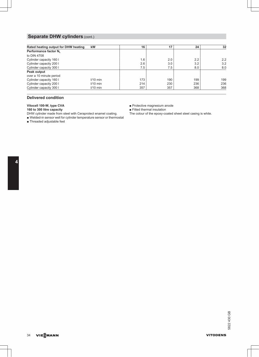
Rated heating output for DHW heating kW 16 17 24 32Performance factor NL to DIN 4708
Cylinder capacity 160 l 1.6 2.0 2.2 2.2Cylinder capacity 200 l 2.6 3.0 3.2 3.2Cylinder capacity 300 l 7.5 7.5 8.0 8.0Peak output over a 10 minute period
Cylinder capacity 160 l l/10 min 173 190 199 199Cylinder capacity 200 l l/10 min 214 230 236 236Cylinder capacity 300 l l/10 min 357 357 368 368
Delivered condition
Vitocell 100-W, type CVA160 to 300 litre capacityDHW cylinder made from steel with Ceraprotect enamel coating.■ Welded-in sensor well for cylinder temperature sensor or thermostat■ Threaded adjustable feet
■ Protective magnesium anode■ Fitted thermal insulationThe colour of the epoxy-coated sheet steel casing is white.
Separate DHW cylinders (cont.)
34 VIESMANN VITODENS
4
5822
430
GB

4.3 Vitocell 300-W adjacent to the boiler (type EVA – 160 and 200 litre, white finish), heatedby a peripheral indirect coil, made from stainless steel■ Installed adjacent to the boiler■ Heated by a peripheral indirect coil, stainless steel(For further technical details, see the separate datasheet for the Vitocell 300-V)
Capacity l 160 200DIN register no. 0166/04-10 MCConnections (male thread) Heating water flow and return R 1 1Hot and cold water R ¾ ¾DHW circulation R ½ ½Permiss. operating pressure – Heating water side bar
MPa3
0.33
0.3– DHW side bar
MPa101
101
Permiss. temperatures – Heating water side °C 110 110– DHW side °C 95 95Standby heat loss qBS at 45 K temp. differential (actualvalues to DIN 4753-8)
kWh/24 h 1.40 1.60
Dimensions Length a (7) mm 633 633Width b mm 667 667Height c mm 1203 1423Weight kg 84 98
hg
a
b
BÖ
HR
ZWW
HV
KW/E
cd
ef
SPR
BÖ Inspection and cleaning apertureE DrainHR Heating returnHV Heating flow
KW Cold waterSPR Sensor well for cylinder temperature sensor or thermostatWW DHWZ DHW circulation
Separate DHW cylinders (cont.)
VITODENS VIESMANN 35
5822
430
GB
4

DimensionsCylinder capacity l 160 200a mm 7 633 7 633b mm 667 667c mm 1203 1423d mm 1067 1287e mm 984 1204g mm 877 1097g mm 155 155h mm 77 77
Pressure drop on the DHW side
120
2400.8
1
5
10
20
50
100
300
360
480
600
900
1200
1800
2400
3000
3600
mba
r
DHW volume in l/h
Pres
sure
dro
p
12
0.080.1
0.5
1
2
5
10
kPa
DHW output data at rated heating outputRated heating output for DHW heating kW 16 17 24 32Continuous DHW output when heating DHW from 10 to 45 °C and withan average boiler water temperature of70 °C
Cylinder capacity 160 l kW 16 17 24 24 l/h 390 415 590 590Cylinder capacity 200 l kW 16 17 24 32 l/h 390 415 590 786Performance factor NL to DIN 4708
Cylinder capacity 160 l 1.6 1.7 1.7 1.7Cylinder capacity 200 l 2.8 2.9 2.9 2.9Peak output over a 10 minute period
Cylinder capacity 160 l l/10 min 173 177 177 177Cylinder capacity 200 l l/10 min 222 226 226 226
Delivered condition
Vitocell 300-W type EVA, peripheral indirect coil160 to 200 litre capacityDHW cylinders made from stainless steel.■ Welded sensor well for cylinder temperature sensor or thermostat■ Integral thermometer
■ Threaded adjustable feet■ Fitted thermal insulationWhite epoxy-coated sheet steel casing.
Separate DHW cylinders (cont.)
36 VIESMANN VITODENS
4
5822
430
GB
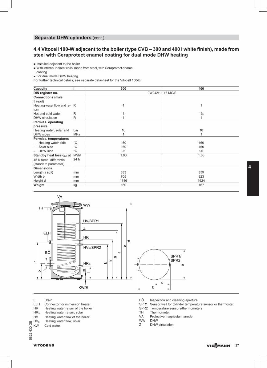
4.4 Vitocell 100-W adjacent to the boiler (type CVB – 300 and 400 l white finish), made fromsteel with Ceraprotect enamel coating for dual mode DHW heating■ Installed adjacent to the boiler■ With internal indirect coils, made from steel, with Ceraprotect enamel
coating■ For dual mode DHW heatingFor further technical details, see separate datasheet for the Vitocell 100-B.
Capacity l 300 400DIN register no. 9W242/11-13 MC/EConnections (malethread)
Heating water flow and re-turn
R 1 1
Hot and cold water R 1 1¼DHW circulation R 1 1Permiss. operatingpressureHeating water, solar andDHW sides
barMPa
101
101
Permiss. temperatures – Heating water side °C 160 160– Solar side °C 160 160– DHW side °C 95 95Standby heat loss qBS at45 K temp. differential(standard parameter)
kWh/24 h
1.00 1.08
Dimensions Length a (7) mm 633 859Width b mm 705 923Height d mm 1746 1624Weight kg 160 167
VA
cb
a
de
fg
hk
lmpr
WW
HV/SPR1
Z
HR
HVs/SPR2
TH
BÖ
ELH
KW/E
HRs
n
SPR1/SPR2
E DrainELH Connector for immersion heaterHR Heating water return of the boilerHRS Heating water return, solarHV Heating water flow of the boilerHVS Heating water flow, solarKW Cold water
BÖ Inspection and cleaning apertureSPR1 Sensor well for cylinder temperature sensor or thermostatSPR2 Temperature sensors/thermometersTH ThermometerVA Protective magnesium anodeWW DHWZ DHW circulation
Separate DHW cylinders (cont.)
VITODENS VIESMANN 37
5822
430
GB
4

DimensionsCylinder capacity l 300 400a mm 7 633 7859b mm 705 923c mm 343 455d mm 1746 1624e mm 1600 1458f mm 1355 1204g mm 1115 1044h mm 995 924k mm 875 804l mm 260 349m mm 76 107n mm 7 100 7 100p mm 333 422r mm 935 864
Recommended positioning of the cylinder temperature sensor for solar operation
A Cylinder temperature sensor(solar control unit)
B Threaded elbow with sensor well(standard delivery)
Pressure drop on the DHW side
500
600
800
1000
2000
3000
4000
5000
0.30.40.50.60.81.0
2.0
3.04.05.06.08.0
10.0
Pres
sure
dro
p in
mba
r
DHW throughput in l/h
34568
10
20
3040506080
100
kPa
A B
6000
8000
A 300 litre capacityB 400 litre capacity
Separate DHW cylinders (cont.)
38 VIESMANN VITODENS
4
5822
430
GB

DHW output data at rated heating outputRated heating outputfor DHW heating
kW 16 17 24 32
Continuous DHW output when heating DHW from 10 to 45 °C andwith an average boiler water tempera-ture of 78 °C
kW 16 17 24 26l/h 390 415 590 638
Performance factor NL*8 to DIN 4708
1.3 1.4 1.4 1.4
Peak output over a 10 minute period
l/10 min 159 164 164 164
Delivered condition
Vitocell 100-W, type CVB, 300 litre capacityDHW cylinder made from steel with Ceraprotect enamel coating.
■ 2 welded sensor wells for cylinder temperature sensor or thermostat■ Threaded elbow with sensor well■ Female connection R 1½ for the installation of an immersion heater
and plug R 1½■ Adjustable feet■ Protective magnesium anode■ Fitted thermal insulationWhite epoxy-coated sheet steel casing.
Vitocell 100-W, type CVB, 400 litre capacityDHW cylinder made from steel with Ceraprotect enamel coating.
■ 2 welded sensor wells for cylinder temperature sensor or thermostat■ Threaded elbow with sensor well■ Female connection R 1½ for the installation of an immersion heater
and plug R 1½■ Adjustable feet■ Protective magnesium anode■ Thermal insulation packed separatelyWhite plastic-coated thermal insulation.
*8 Values for the upper internal indirect coil
Separate DHW cylinders (cont.)
VITODENS VIESMANN 39
5822
430
GB
4

4.5 Vitocell 100-W adjacent to the boiler (type CVUA – 300 l, white finish), made from steel,with Ceraprotect enamel coating for dual mode DHW heating■ Installed adjacent to the boiler■ With internal indirect coils, made from steel, with Ceraprotect enamel
coating■ For dual mode DHW heating■ With Solar-Divicon, integral pipework and solar control module, type
SM1.For further technical details, see separate datasheet for the Vitocell 100-U.
Capacity l 300DIN register no. 0266/07-13 MC/EConnections Heating water flow and return R 1Hot and cold water R 1DHW circulation R 1Permiss. operating pressure – Heating water, solar and DHW sides bar 10Permiss. temperatures – Heating water side °C 160– Solar side °C 110– DHW side °C 95Standby heat loss (standard parameter) kWh/24 h 1.00qBS at 45 K temp. differential Dimensions Length (Ø) mm 631Width mm 780Height mm 1705Height when tilted mm 1790Weight incl. thermal insulation kg 179Total weight in operation kg 481
SPR
1
844
343
b
a
c16
0113
5611
1699
6
761
261 77
WW/HVs/HRs
VA
KW/E
TH
TE
SPR2
HV/SPR1
ZHR
HVs
HR
s86
86
A
E DrainHR Heating water return
(upper indirect coil)HRs Heating water return, solar (lower indirect coil; fit the cylinder
temperature sensor into the solar heating water return (HRs)using the threaded elbow with sensor well SPR2 from thestandard delivery)
HV Heating water flow (upper indirect coil)HVs Heating water flow, solar (lower indirect coil)KW Cold water
SPR1 Cylinder temperature sensor of the cylinder temperature con-troller
SPR2 Cylinder temperature sensor of the solar thermal systemTE Sensor well for lower thermometerTH ThermometerVA Protective magnesium anodeWW DHW to the pipework
Separate DHW cylinders (cont.)
40 VIESMANN VITODENS
4
5822
430
GB

Z DHW circulationA Lower indirect coil (solar)
The connections HVs and HRs are located at the top of theDHW cylinder
DimensionsDimensions Dimensions in mma 631b 780c 1705
Pressure drop on the DHW side
500
600
800
1000
2000
3000
4000
5000
0.30.40.50.60.8
1
2
34568
10
Pres
sure
dro
pm
bar
DHW throughput in l/h
34568
10
20
3040506080
100
kPa
6000
8000
DHW output data at rated heating outputRated heating outputfor DHW heating
kW 16 17 24 32
Continuous DHW output when heating DHW from 10 to 45 °C andwith an average boiler water tempera-ture of 78 °C
kW 16 17 26 26l/h 390 415 638 638
Performance factor NL*9 to DIN 4708
1.3 1.4 1.4 1.4
Peak output over a 10 minute period
l/10 min 159 164 164 164
Delivered condition
Dual mode DHW cylinder made from steel with Ceraprotect enamelcoating and Solar-Set.
■ Solar-Set, comprising:– Solar circuit pump (variable speed high efficiency circulation
pump)– 2 thermometers– 2 ball valves with check valve– Flow meter– Pressure gauge– Safety valve 6 bar– Fill valve– Air separator– Solar control module, type SM1 with electronic temperature dif-
ferential control– Cylinder temperature sensor– Collector temperature sensor
■ 2 welded sensor wells for cylinder temperature sensor or thermostat
■ Threaded elbow with sensor well■ Adjustable feet■ Protective magnesium anode■ Thermal insulation made from rigid PUR foamWhite epoxy-coated sheet steel casing.
*9 Values for the upper internal indirect coil
Separate DHW cylinders (cont.)
VITODENS VIESMANN 41
5822
430
GB
4

5.1 Installation accessories for Vitodens 200-W and 300-W
Vitodens 200-W installation directly on a wall
Gas condensing combi boiler
Pre-plumbing jig for finished wallsPart no. Z002 350Comprising:■ Fixings■ Valves/fittings■ Straight-through gas valve Rp ½ with thermally activated safety shut-
off valve
Pre-plumbing jig for unfinished wallsPart no. Z002 349Comprising:■ Fixings■ Valves/fittings■ Gas angle valve R ½ with thermally activated safety shut-off valve
Gas condensing boiler
Pre-plumbing jig for finished wallsPart no. Z002 337Comprising:■ Fixings■ Valves/fittings■ Straight-through gas valve Rp ½ with thermally activated safety shut-
off valve
Pre-plumbing jig for unfinished wallsPart no. Z002 348Comprising:■ Fixings■ Valves/fittings■ Gas angle valve R ½ with thermally activated safety shut-off valve
Installing the Vitodens 300-W directly on a wall
Gas condensing boiler
Pre-plumbing jig for finished wallsPart no. ZK00 023Comprising:■ Fixings■ Valves/fittings■ Straight-through gas valve Rp ½ with thermally activated safety shut-
off valve
Pre-plumbing jig for unfinished wallsPart no. ZK00 024Comprising:
Installation accessories
42 VIESMANN VITODENS
5
5822
430
GB
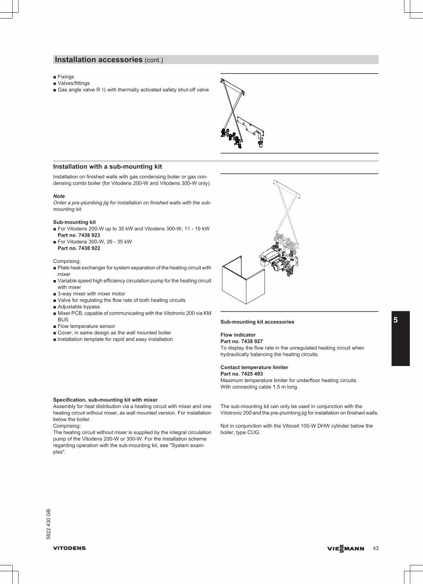
■ Fixings■ Valves/fittings■ Gas angle valve R ½ with thermally activated safety shut-off valve
Installation with a sub-mounting kitInstallation on finished walls with gas condensing boiler or gas con-densing combi boiler (for Vitodens 200-W and Vitodens 300-W only).
NoteOrder a pre-plumbing jig for installation on finished walls with the sub-mounting kit.
Sub-mounting kit■ For Vitodens 200-W up to 35 kW and Vitodens 300-W, 11 - 19 kW
Part no. 7438 923■ For Vitodens 300-W, 26 - 35 kW
Part no. 7438 922
Comprising:■ Plate heat exchanger for system separation of the heating circuit with
mixer■ Variable speed high efficiency circulation pump for the heating circuit
with mixer■ 3-way mixer with mixer motor■ Valve for regulating the flow rate of both heating circuits■ Adjustable bypass■ Mixer PCB, capable of communicating with the Vitotronic 200 via KM
BUS■ Flow temperature sensor■ Cover, in same design as the wall mounted boiler■ Installation template for rapid and easy installation
Sub-mounting kit accessories
Flow indicatorPart no. 7438 927To display the flow rate in the unregulated heating circuit whenhydraulically balancing the heating circuits.
Contact temperature limiterPart no. 7425 493Maximum temperature limiter for underfloor heating circuits.With connecting cable 1.5 m long.
Specification, sub-mounting kit with mixerAssembly for heat distribution via a heating circuit with mixer and oneheating circuit without mixer, as wall mounted version. For installationbelow the boiler.Comprising:The heating circuit without mixer is supplied by the integral circulationpump of the Vitodens 200-W or 300-W. For the installation schemeregarding operation with the sub-mounting kit, see "System exam-ples".
The sub-mounting kit can only be used in conjunction with theVitotronic 200 and the pre-plumbing jig for installation on finished walls.
Not in conjunction with the Vitocell 100-W DHW cylinder below theboiler, type CUG.
Installation accessories (cont.)
VITODENS VIESMANN 43
5822
430
GB
5

a380
50
120170
HV2HR2 HR1HV1GA
130130195
330
390
GA Gas connection Rp ½HR1 Heating return, heating circuit without mixer R ¾HR2 Heating return, heating circuit with mixer R ¾
HV1 Heating flow, heating circuit without mixer R ¾HV2 Heating flow, heating circuit with mixer R ¾
Max. transferable heating output of the heatingcircuit with mixer (ΔT 10 K)
kW 14
Max. flow rate of the heating circuit with mixer(ΔT 10 K)
l/h 1200
Permiss. operating pressure bar 3 MPa 0.3Max. power consumption (total) W 48Dim. a– Vitodens 200-W up to 35 kW and 300-W up
to 19 kWmm 450
– Vitodens 300-W, 26 and 35 kW mm 480Weight (incl. packaging) kg 17
Residual head of the integral circulation pump for the heating circuit with mixer
0
100
200
300
400
500
0
10
20
30
40
50
kPa
600 60
300 400 500 600 700 800 900 1000 1100 1200Flow rate in l/h
1300 14002001000Min.
Max.
Res
idua
l hea
dm
bar
Calculating the transferable heating output (examples)The sub-mounting kit is equipped with an integral balancing valve. Thisallows the flow rate via the plate heat exchanger to the regulated heat-ing circuit to be restricted as required.
The maximum heating output that can be transferred via the plate heatexchanger of the sub-mounting kit is 14 kW. For balanced flow ratesbetween the regulated heating circuit (sub-mounting kit) and theunregulated heating circuit (radiator heating circuit), the pressure dropin the sub-mounting kit must be increased. The integral balancingvalve is used for this purpose.
Installation accessories (cont.)
44 VIESMANN VITODENS
5
5822
430
GB

For accurate adjustment of the flow rates, a flow indicator (availableas an accessory) can be fitted into the flow line of the unregulatedheating circuit. The rated circulation water volume of the boiler (seespecification), minus the flow rate through the plate heat exchanger ofthe sub-mounting kit, results in the flow rate of the unregulated heatingcircuit.
Example:
Vitodens 300-W, 4.0 -26 kW■ Rated circulation water volume at ΔT 20 K: 1018 l/h■ Heating output for regulated heating circuit (assumed): 13 kW
■ Resulting flow rate, primary side, plate heat exchanger at ΔT 20 K:560 l/h
■ Flow rate of unregulated heating circuit (to be adjusted via the bal-ancing valve): 1018 l/h – 560 l/h = 458 l/h
Installation of the Vitodens 300-W with mounting frame
Mounting frame consisting of:■ Diaphragm expansion vessel, rated capacity 18 l■ Fittings on the heating water and DHW side■ Boiler drain & fill valve■ Gas angle valve R ½ with integral thermally activated safety shut-off
valve■ Flexible connection line for the diaphragm expansion vessel
All fittings are located under the boiler covers.
Mounting frameOnly for Vitodens 300-W, 26 and 35 kW.■ For installation on finished walls with threaded fittings
Part no. ZK00 277■ For installation on unfinished walls
Part no. ZK00 278
Installation with a self-supporting mounting frame
Self-supporting mounting frameWith valves and gas angle valve G ¾ with thermally activated safetyshut-off valve■ For Vitodens 200-W gas condensing combi boiler with threaded fit-
tingPart no. Z002 352
■ For Vitodens 200-W gas condensing boiler with threaded fittingPart no. Z002 354
■ For Vitodens 300-W gas condensing boiler with threaded fittingPart no. ZK00 025
Ceiling extension for self-supporting mounting framePart no. 7329 151For "self-supporting" installation in a room.
Installation accessories (cont.)
VITODENS VIESMANN 45
5822
430
GB
5

Further accessories
Safety assembly to DIN 1988Comprising:■ Shut-off valve■ Non-return valve and test nipple■ Pressure gauge connector■ Diaphragm safety valve
– 10 bar (1 MPa)– DN 15, up to 200 litre cylinder capacity
Part no. 7219 722– DN 20, for 300 litre cylinder capacity
Part no. 7180 662–a 6 bar (0.6 MPa)
– DN 15, up to 200 litre cylinder capacityPart no. 7265 023
– DN 20, for 300 litre cylinder capacityPart no. 7179 666
For Vitocell 100-W below the boiler– 10 bar (1 MPa), DN 15, right angle version
Part no. 7180 097–a 6 bar (0.6 MPa), DN 15, right angle version
Part no. 7179 457
Pressure reducer (DN 15)Part no. 7180 148To match the the right angle version of the safety assembly.
Drain outlet kitPart no. 7459 591Drain outlet with siphon and rose for connecting the drain lines of thesafety valves and condensate drain.Drain connection G1
Valve/fittings cover■ For the Vitodens 200-W and Vitodens 300-W, 1.9 to 19 kW
Part no. 7438 096■ For the Vitodens 300-W, 4.0 to 35 kW
Part no. 7438 094Cannot be used in conjunction with DHW cylinders installed below theboiler.
Neutralising system
Part no. 7252 666With neutralising granulate
310 DN 40
145
Neutralising granulate
Part no. 9524 670(2 × 1.3 kg)
Condensate lifting system
Part no. 7374 796Automatic condensate lifting system for condensate with a pH value≥ 2.7 from oil and gas condensing boilers.Components:■ Condensate container 0.5 l■ Shaftless permanent magnet ball motor pump■ Control unit for pump operation, display of operating conditions and
fault messages■ 2 m long power cable with plug■ Two 7 24 mm connection apertures for condensate inletThe standard delivery comprises:■ 6 m long drain hose 7 14 x 2 mm■ Non-return valve
Installation accessories (cont.)
46 VIESMANN VITODENS
5
5822
430
GB

2000
90
168
148
118
A B C
A Condensate inletB Condensate inlet with drain plugC Condensate drain
SpecificationRated voltage 230 V~Rated frequency 50 HzPower consumption 20 WIP rating IP 44 Protection class FPermissible medium temperature +60 °CMax. head 45 kPaMax. capacity 450 l/hZero volt contact N/C, breaking capacity
230 VA
Service accessories for automatic hydraulic balancingSee pricelist.
Plate heat exchanger flushing systemPart no. 7373 005For Vitodens 200-W.
Small softening system for heating waterFor filling heating circuits.See Vitoset pricelist.
CO limiter
Part no. 7499 330A monitoring device that safely shuts down the boiler in the event ofcarbon monoxide being released.Wall mounting in the ceiling area near the boiler.Can be used for boilers built from 2004 onwards.
Components:■ Casing with integrated CO sensor, relay and displays for operation
and alarm.■ Fixing materials.■ Power cable (2.0 m long).■ Connecting cable, relay for burner shutdown (2.0 m long).
70 45
117
SpecificationRated voltage 230 V~Rated frequency 50 HzPower consumption 3.5 WRated breaking capacity of the relay out-put
8 A 230 V~
Alarm threshold 40 ppm COSafety category IIIP rating IP 20 to EN 60529; ensure
through design/installationPermissible ambient temperature 70 °C
Connections between the Vitodens and the DHW cylinder
Connection set with connecting pipes, for Vitocell 100-W DHWcylinder installed below the boiler (type CUG)Part no. 7178 347Comprising:■ Cylinder temperature sensor■ Heating water connecting pipes■ DHW connecting pipesInstallation on finished or unfinished walls
Casing for connecting pipesWith thermometer for the Vitocell 100, type CUG.■ For DHW cylinder with 120 litre capacity
Part no. 7179 030■ For DHW cylinder with 150 litre capacity
Part no. 7179 031
Connection set for Vitocell 100-W and 300-W DHW cylindersinstalled adjacent to the boilerComprising:■ Cylinder temperature sensor■ Connection fittingsDHW cylinder adjacent to the Vitodens, either on the left or right.
Installation accessories (cont.)
VITODENS VIESMANN 47
5822
430
GB
5

■ Threaded fitting versionPart no. 7178 349
■ Solder versionPart no. 7178 348
Installation accessories (cont.)
48 VIESMANN VITODENS
5
5822
430
GB

5.2 Installation accessories Vitodens 222-W
Pre-plumbing jig for finished walls■ Diaphragm safety valve 10 bar (1 MPa)
Part no. 7248 408■a Diaphragm safety valve 6 bar (0.6 MPa)
Part no. 7248 406Comprising:■ Fixings■ Valves/fittings■ Gas angle valve R ½ with thermally activated safety shut-off valve■ Safety valve on the DHW side■ Pipe bends
Pre-plumbing jig for unfinished walls■ Diaphragm safety valve 10 bar (1 MPa)
Part no. 7248 401■a Diaphragm safety valve 6 bar (0.6 MPa)
Part no. 7248 400Comprising:■ Fixings■ Valves/fittings■ Gas angle valve R ½ with thermally activated safety shut-off valve■ Safety valve on the DHW side■ Connection pieces
Further accessories
Valve/fittings cover
Part no. 7438 340
Neutralising system
Part no. 7252 666With neutralising granulate
310 DN 40
145
Neutralising granulate
Part no. 9524 670(2 × 1.3 kg)
Safety assembly to DIN 1988
Comprising:■ Shut-off valve■ Non-return valve and test nipple■ Pressure gauge connector■ Diaphragm safety valve
■ 10 bar (1 MPa), DN 15Part no. 7219 722
■a 6 bar (0.6 MPa), DN 15Part no. 7265 023
Installation accessories (cont.)
VITODENS VIESMANN 49
5822
430
GB
5

Drain outlet kit
Part no. 7459 591Drain outlet with siphon and rose.
For connecting the drain lines of the safety valves and condensatedrain.
Condensate lifting system
Part no. 7374 796Automatic condensate lifting system for condensate with a pH value≥ 2.7 from oil and gas condensing boilers.Components:■ Condensate container 0.5 l■ Shaftless permanent magnet ball motor pump■ Control unit for pump operation, display of operating conditions and
fault messages■ 2 m long power cable with plug■ Two 7 24 mm connection apertures for condensate inletThe standard delivery comprises:■ 6 m long drain hose 7 14 x 2 mm■ Non-return valve
2000
90
168
148
118
A B C
A Condensate inletB Condensate inlet with drain plugC Condensate drain
SpecificationRated voltage 230 V~Rated frequency 50 HzPower consumption 20 WIP rating IP 44 Protection class FPermissible medium temperature +60 °CMax. head 45 kPaMax. capacity 450 l/hZero volt contact N/C, breaking capacity
230 VA
Service accessories for automatic hydraulic balancingSee pricelist.
Plate heat exchanger flushing systemPart no. 7373 005
Small softening system for heating waterFor filling heating circuits.See Vitoset pricelist.
CO limiter
Part no. 7499 330A monitoring device that safely shuts down the boiler in the event ofcarbon monoxide being released.Wall mounting in the ceiling area near the boiler.Can be used for boilers built from 2004 onwards.
Components:■ Casing with integrated CO sensor, relay and displays for operation
and alarm.■ Fixing materials.■ Power cable (2.0 m long).■ Connecting cable, relay for burner shutdown (2.0 m long).
70 45
117
SpecificationRated voltage 230 V~Rated frequency 50 HzPower consumption 3.5 WRated breaking capacity of the relay out-put
8 A 230 V~
Alarm threshold 40 ppm COSafety category IIIP rating IP 20 to EN 60529; ensure
through design/installationPermissible ambient temperature 70 °C
Flue gas cascade (positive pressure) for multi boiler systems with Vitodens 200-W and 222-WComprising:■ Flue gas non-return device for each boiler■ Flue gas header■ End piece with condensate drain and siphon
Installation accessories (cont.)
50 VIESMANN VITODENS
5
5822
430
GB

A
C
B B B B
A Flue gas headerB Flue gas non-return device (for installation in the Vitodens)C End piece with siphon
■ 2-boiler system– Part no. Z008 385
■ 3-boiler system– Part no. Z008 386
■ 4-boiler system– Part no. Z008 387
Design information
6.1 Positioning, installation
Siting conditions for open flue operation (appliance type B)(Type B23 and B33)
In rooms where air contamination through halogenated hydrocar-bons can occur, such as hairdressing salons, printing shops, chemicalcleaners, laboratories, etc., install the Vitodens only as a balanced fluesystem.If in doubt, please contact us.Wall mounted boilers should not be installed in areas subject to verydusty conditions.The installation location must be kept free from frost and must be ade-quately ventilated.Provide a condensate drain and a discharge pipe for the safety valvein the installation room.The maximum ambient temperature at the system should not exceed35 °C.If these instructions are not observed, any consequential appliancedamage directly related to any of these causes is excluded from ourwarranty.a When installing in Austria, observe all current safety regulations
as defined by ÖVGW-TR Gas (G1), ÖNORM, ÖVGW, ÖVE andlocally applicable standards.
Multi boiler systems with flue systems under positive or negativepressureSystems with several Vitodens with separate hydraulic connectionsrequire a flue gas cascade suitable for positive or negative pressure(see technical guide "Flue systems for the Vitodens") or individual fluegas routing for each boiler.
Installation room
Permissible:■ Gas appliance installation on the same floor■ Living space with interconnected room air supply■ Adjacent rooms with interconnected room air supply (larders, base-
ments, utility rooms, etc.)■ Utility rooms with vents to the outside (ventilation air/extract air
150 cm2 or 2 × 75 cm2 each at the top and bottom of the same wall,up to 35 kW)
■ Attic rooms, but only with adequate minimum chimney height toDIN 18160 – 4 m above inlet (negative pressure operation).
Not permissible:■ Stairwells and communal hallways; exception: Detached and two-
family houses of low height (top edge of floor in the top storey <7 m above ground level)
■ Bathrooms and toilets without outside windows with shaft ventilation■ Rooms where explosive or flammable materials are stored■ Rooms that are ventilated mechanically or via individual duct sys-
tems to DIN 18117-1.
Observe all local fire regulations.
Connection on the flue gas side(For further details, see the technical guide "Flue systems for theVitodens")The connection piece to the chimney should be as short as possible.Therefore position the Vitodens as close to the chimney as possible.No special protective measures or clearances towards combustibleobjects, e.g. furniture, packaging, etc., need to be taken/observed.The surface temperatures of the Vitodens and the flue system do notexceed 85 °C at any point.
ExtractorsWhen installing appliances with extraction to the outside (cookerhoods, extractor fans etc.), ensure that air extraction will not createnegative pressure inside the installation room. A return flow of fluegases could result, if the ventilation system and the Vitodens are oper-ated simultaneously. In such cases, install an interlock circuit.
Safety equipment for the installation roomViessmann boilers are tested and approved in accordance with allsafety specifications, and are therefore fail-safe. Unforeseeable exter-nal influences may very occasionally lead to harmful carbon monoxide(CO) escaping. In this instance, we recommend using a CO limiter.This can be ordered as a separate accessory (part no. 7499 330).
Installation accessories (cont.)
VITODENS VIESMANN 51
5822
430
GB
6

Installation conditions for balanced flue operation (appliance type C)The Vitodens can be installed as appliance type C13x, C33x, C43x, C53x,C63x, C83x or C93x to TRGl 2008, for balanced flue operation inde-pendent of the size and ventilation of the installation room.It may, for example, be installed in recreation rooms, in other livingspaces, in ancillary rooms without ventilation, in cupboards (open atthe top) and recesses, without maintaining minimum clearances tocombustible parts, as well as in attic rooms (pitched attics and longpanes) where the balanced flue pipe can be routed directly through theroof. Since the flue pipe connection for balanced flue operation is sur-rounded by combustion air (coaxial pipe), no clearances towards com-bustible parts need to be maintained (for further details, see the tech-nical guide "Flue systems for the Vitodens").The installation room must be safe from the risk of frost.Provide a condensate drain and a discharge pipe for the safety valvein the installation room.Electrical interlocks for extractors (extractor hoods, etc.) are notrequired with balanced flue operation.
Installation in a garageTests carried out by the Gaswärme-Institut e.V., Essen, have con-firmed that the Vitodens is suitable for installation in garages.When installing this boiler in garages, maintain a clearance betweenthe floor and the burner of at least 500 mm. Install a frame or deflector(provided on site) to protect the boiler against mechanical damage.
Safety equipment for the installation roomViessmann boilers are tested and approved in accordance with allsafety specifications, and are therefore fail-safe. Unforeseeable exter-nal influences may very occasionally lead to harmful carbon monoxide(CO) escaping. In this instance, we recommend using a CO limiter.This can be ordered as a separate accessory (part no. 7499 330).
Intended use
The appliance is only intended to be installed and operated in sealedunvented heating systems that comply with EN 12828, with due atten-tion paid to the associated installation, service and operating instruc-tions. It is only designed for the heating of water that is of potable waterquality.
Intended usage presupposes that a fixed installation in conjunctionwith permissible, system-specific components has been carried out.
Commercial or industrial usage for a purpose other than heating thebuilding or DHW does not comply with regulations.
Any usage beyond this must be approved by the manufacturer for theindividual case.
Incorrect usage or operation of the appliance (e.g. the appliance beingopened by the system user) is prohibited and results in an exclusionof liability. Incorrect usage also occurs if the components in the heatingsystem are modified from their intended function (e.g. if the flue gasand ventilation air paths are sealed).
Operation of the Vitodens in wet areasThe Vitodens is approved for installation in wet areas (e.g. bath orshower rooms) (protection IP X4 D, splashproof).When installing the Vitodens in wet areas, observe the safety zonesand minimum wall clearances according to VDE 0100 [or local regu-lations] (see also "Electrical safety area"). The Vitodens may be instal-led in safety area 1 if hosed water (e.g. from massage showers) isprevented.
Electrical safety area
Area 0
Area 1Area
2
Area 2
600
2250
Electrical equipment in rooms containing a bathtub or a shower mustbe installed in such a way that users cannot be exposed to dangerousbody currents.The VDE 0100 specifies that cables supplying permanently installedconsumers in areas 1 and 2 should only be run vertically and routedinto the equipment from the back.
Electrical connectionThe power supply must comply with the requirements of your localpower supply utility and current VDE [or local] regulations (a: ÖVEregulations).
Protect the power cable with a fuse with a maximum rating of 16 A.We recommend installing an AC/DC-sensitive RCD (RCD class B) forDC (fault) currents that can occur with energy efficient equipment.
Design information (cont.)
52 VIESMANN VITODENS
658
22 4
30 G
B

Make the power supply (230 V~, 50 Hz) via a permanent connection.Connect the supply cables and accessories at the terminals inside theboiler.Allow cables/leads in the shaded area to protrude at least 800 mm fromthe wall (see diagram).
730
50215100
B
A
Vitodens 200-W and 300-W
A Reference point Vitodens top edgeB Area for power cables
740
70
90
265
Vitodens 222-W
A Reference point Vitodens top edgeB Area for power cables
Recommended leads/cables
NYM 3 G 1.5 mm2 2-core min. 0.75 mm2 4-core 1.5 mm2
or3-core 1.5 mm2 without green/yellowwire
– Power cables (also for accessories)– DHW circulation pump
– Extension AM1 or EA1– Outside temperature sensor– Vitotronic 200-H (LON)– Extension kit for heating circuit with mixer
(KM BUS)– Vitotrol 100, type UTDB (230 V)– Vitotrol 200A– Vitotrol 300A– Vitocomfort 200– Wireless base station– Radio clock receiver
– Vitotrol 100, type UTDB-RF (230 V)– Vitotrol 100, type UTA
Interlock switchInstall an interlock for open flue operation if an extractor (e.g. cookerhood) is fitted any room that is part of the interconnected combustionair supply.For this, the internal extension H2 (accessories) can be used. Thisswitches the extractors off when the burner is started.
Power supply for accessoriesThe power supply for accessories can be connected directly to thecontrol unit.This connection is switched by the system ON/OFF switch.If the total system current exceeds 6 A, connect one or more exten-sions via an ON/OFF switch directly to the mains supply.Where the boiler is installed in a wet area, the power supply connectionof accessories must not be made at the control unit.
Additional requirements when installing boilers with LPG opera-tion in rooms below ground levelAccording to TRF 1996 Vol. 2 – valid as of 1 September 1997 – anexternal safety solenoid valve is no longer required when installing theVitodens below ground level.However, the high safety standard derived from the use of an externalsafety solenoid valve has proved to be valuable. We therefore recom-mend the installation of an external safety solenoid valve when instal-ling the boiler in rooms below ground level. This requires the internalextension H1 (included in the standard delivery for the Vitodens 222-W and Vitodens 300-W).
Design information (cont.)
VITODENS VIESMANN 53
5822
430
GB
6

Gas connectionGas installations must only be carried out by a registered gas fitterauthorised by the relevant gas supply utility.Connect and size the mains gas according to TRGI 2008 or TRF 1996[or local regulations].a Connect the mains gas according to ÖVGW-TR Gas (G1) and
the regionally applicable Building Regulations.Max. test pressure 150 mbar (15 kPa).We recommend the installation of a gas filter to DIN 3386 into the gassupply line.
Thermally activated safety shut-off valveAccording to paragraph 4, section 5 of the FeuVo 2008, thermally acti-vated shut-off equipment that will shut off the gas supply if the externaltemperature exceeds 100 °C must be installed in combustion equip-ment or in gas supply lines immediately upstream of the combustionequipment. These valves must isolate the gas supply for at least 30minutes up to a temperature of 650 °C. This is intended to prevent theformation of explosive gas mixtures in the event of a fire.
The gas shut-off valves supplied with the Vitodens are equipped withintegral thermally activated safety shut-off valves.
Gas supply lineThe following table is designed to assist in the approximate sizing ofthe on-site gas supply line.For each 90° bend 1 m is deducted from the max. possible pipelength.Checking your calculations against TRGI and TRF [or local regula-tions] is recommended.
Rated heat input Gas type Connection values Nominal diameter of the gas supplyline
kW m3/h kg/h DN 15 DN 20 DN 25Max. possible pipe length in m
16.7 Natural gas E 1.77 13 60 –Natural gas LL 2.05 8 40 127LPG 1.31 80 – –
17.9 Natural gas E 1.89 8 40 127Natural gas LL 2.20 6 28 91LPG 1.40 62 – –
24.7 Natural gas E 2.61 6 28 91Natural gas LL 3.04 4 21 68LPG 1.93 36 156 –
30.5 Natural gas E 3.23 4 21 68Natural gas LL 3.75 – 16 53LPG 2.38 23 100 –
33.3 Natural gas E 3.52 4 21 68Natural gas LL 4.10 – 16 53LPG 2.60 23 100 –
34.9 Natural gas E 3.86 4 21 68Natural gas LL 4.49 – 16 53LPG 2.85 23 100 –
Sizing recommendation, gas flow switchIn supply areas with HIB below 8.6 kWh/m3 and gas appliances com-pliant with category I2N, determine a fictitious rated heat input. Thisfictitious rated heat input results from the rated heat input (QNB) of theappliance, multiplied by a factor of 1.23 (ratio HIB 8.6/7.0). Select thegas flow switch and size the pipework in accordance with the TRGI2008 [or local regulations] using this fictitious rated heat input.
Rated heating output - Vitodens Gas flow switch For natural gas
kW11 to 19 GS 426 GS 635 (gas condensing boilers) GS 635 (gas condensing combi boilers andVitodens 222-W)
GS 10
The sizing recommendation for the gas flow switch does not waive therequirement for sizing the pipework correctly.
Minimum clearancesMaintain a clearance of 700 mm in front of the Vitodens or the DHWcylinder for maintenance purposes.
Maintenance clearances to the l.h. or r.h. side of the Vitodens arenot required.
Pre-installation for mounting the Vitodens 200-W and 300-W directly on the wall – Installation on finishedwalls
Accessories required for installation without DHW cylinder
Pre-plumbing jigWith fixing components, valves and gas shut-off valve Rp ½ with inte-gral thermally activated safety shut-off valve
Additional requirements when connecting a DHW cylinderConnection set for DHW cylinders
Design information (cont.)
54 VIESMANN VITODENS
658
22 4
30 G
B

CBA
EHR
SRL/KW
GAHV
OKFF
1933
+15
0D
SVL/WW
Showing pre-plumbing jig for Vitodens 200-W
A VitodensB Pre-plumbing jigC Area for power cables.
Allow all cables to protrude approx. 800 mm from the wall.D Compulsory in conjunction with DHW cylinders below the
boiler. Otherwise recommendation only.E DrainGA Gas connection Rp ½
HR Heating return Rp ¾HV Heating flow Rp ¾KW Cold water Rp ½ (gas combi boiler)OKFF Top edge, finished floorWW DHW Rp ½ (gas combi boiler)SRL Cylinder return G ¾ (gas boiler)SVL Cylinder flow G ¾ (gas boiler)
Pre-installation with the sub-mounting kit with mixer – installation on finished wallsRequired accessories:■ Sub-mounting kit:
With plate heat exchanger, circulation pump, 3-way mixer, bypass,mixer electronics, flow temperature sensor, cover and installationtemplate
■ Pre-plumbing jig:With fixing components, valves and gas shut-off valve Rp ½ withintegral thermally activated safety shut-off valve
■ Connection set for DHW cylinders (if installed)Not in conjunction with the Vitocell 100-W DHW cylinder installedbelow the boiler.
For specification and accessories for the sub-mounting kit, seepage 43.Install a drain & fill valve on site in the flow of the heating circuit withmixer (HV2).
Design information (cont.)
VITODENS VIESMANN 55
5822
430
GB
6

1933
OKFF
SVL/WWSRL/KW
C
D
A B
F
E
HR1GA
HR2HV2
HV1
Showing sub-mounting kit for Vitodens 200-W
A VitodensB Pre-plumbing jigC Area for power cables.
Allow all cables to protrude approx. 800 mm from the wall.D RecommendationE Sub-mounting kitF Sub-mounting kit cover GA Gas connection R ½HR1 Heating return, heating circuit without mixer R ¾
HR2 Heating return, heating circuit with mixer R ¾HV1 Heating flow, heating circuit without mixer R ¾HV2 Heating flow, heating circuit with mixer R ¾KW Cold water G ½ (gas combi boiler)OKFF Top edge, finished floorWW DHW G ½ (gas combi boiler)SRL Cylinder return G ¾ (gas boiler)SVL Cylinder flow G ¾ (gas boiler)
Pre-installation for mounting the Vitodens 200-W and 300-W directly on the wall – Installation on unfinishedwalls
Accessories required for installation without DHW cylinder
Pre-plumbing jigWith fixing components, valves and gas shut-off valve R ½ with integralthermally activated safety shut-off valve.
Additional requirements when connecting a DHW cylinderConnection set for DHW cylinders.
Design information (cont.)
56 VIESMANN VITODENS
658
22 4
30 G
B

B
OKFF
1933
+15
0E
HR
HVGA
E
SVL/WW
ATR
C
A
941D
125
SRL/KW
Illustration: Connection layout for the Vitodens 200-W gas system boiler
A VitodensB Pre-plumbing jigC Area for power cables.
Allow cables to protrude approx. 800 mm from the wall.D Cold water and DHW connections in conjunction with DHW
cylinder installed below the boiler.E Compulsory in conjunction with DHW cylinders below the
boiler. Otherwise recommendation only.ATR Drain outlet connection R 1
E DrainGA Gas connection R ½HR Heating return G ¾HV Heating flow G ¾KW Cold water G ½ (gas combi boiler)OKFF Top edge, finished floorWW DHW G ½ (gas combi boiler)SRL Cylinder return G ¾ (gas boiler)SVL Cylinder flow G ¾ (gas boiler)
Pre-installation with mounting frame
Mounting frame with expansion vessel for Vitodens 300-W (26and 35 kW)With diaphragm expansion vessel (rated capacity 18 litres), valves,fixing elements and gas angle valve G ¾ with thermally activatedsafety shut-off valve.With valves with threaded fitting■ For installation on finished walls■ For installation on unfinished walls
All fittings are located inside the boiler casing.
NoteMinimum clearance between mounting frame and ceiling for removalof the expansion vessel: 400 mm.
Design information (cont.)
VITODENS VIESMANN 57
5822
430
GB
6
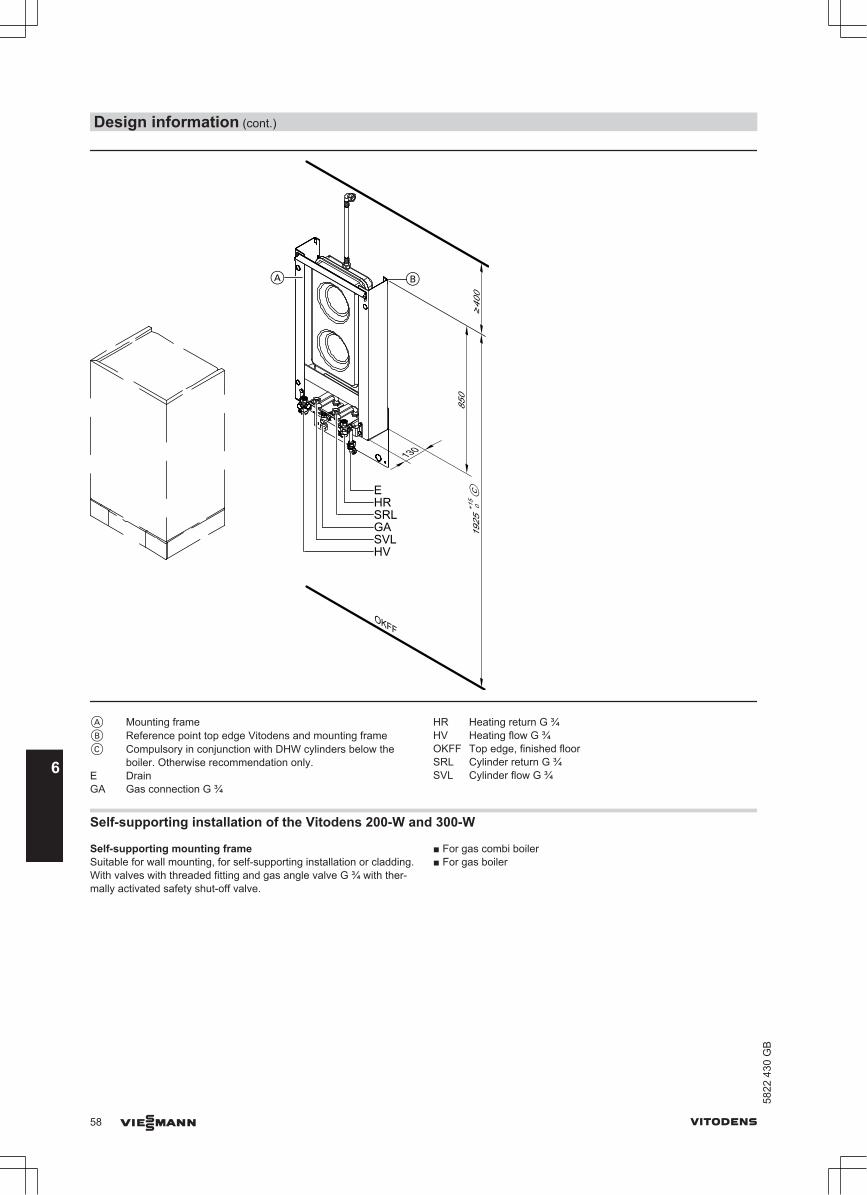
850
OKFF
1925
+15
0C
400
130
A B
EHR
GASRL
SVLHV
A Mounting frameB Reference point top edge Vitodens and mounting frameC Compulsory in conjunction with DHW cylinders below the
boiler. Otherwise recommendation only.E DrainGA Gas connection G ¾
HR Heating return G ¾HV Heating flow G ¾OKFF Top edge, finished floorSRL Cylinder return G ¾SVL Cylinder flow G ¾
Self-supporting installation of the Vitodens 200-W and 300-W
Self-supporting mounting frameSuitable for wall mounting, for self-supporting installation or cladding.With valves with threaded fitting and gas angle valve G ¾ with ther-mally activated safety shut-off valve.
■ For gas combi boiler■ For gas boiler
Design information (cont.)
58 VIESMANN VITODENS
658
22 4
30 G
B

520
≤ 11
50
≤ 20
00
≥ 24
00 - ≤
3000
F
D
B
C
A
E
SVLGA
SRLHR
HVWW
GAKW
HR
HV
Showing mounting brackets for Vitodens 200-W
A Self-supporting mounting frame for the Vitodens incl. connectionbracket
B Ceiling fixing extension (Vitodens)C VitodensD Gas combi boiler connection bracketE Gas boiler connection bracketF In conjunction with DHW cylinder installed below the boiler, min.
1933 mm
GA Gas connection R ½HR Heating return G ¾HV Heating flow G ¾KW Cold water G ½ (gas combi boiler)WW DHW G ½ (gas combi boiler)SRL Cylinder return G ¾ (gas boiler)SVL Cylinder flow G ¾ (gas boiler)
Pre-installation for Vitodens 222-W
Pre-installation on finished wallsAccessories required for installation in unfinished buildings:Pre-plumbing jig, comprising:
Fixings, valves, gas shut-off valve, safety valve on the DHW side andpipe bends.
Design information (cont.)
VITODENS VIESMANN 59
5822
430
GB
6

E
SIV
WW
HV
HR
GA
KW
A B C
A Pre-plumbing jigB Vitodens positionC Area for power cables.
Allow cables to protrude approx. 1300 mm from the wall.E DrainGA Gas connection R ½
HR Heating return R ¾HV Heating flow R ¾KW Cold water R ½SIV Safety valve on the DHW sideWW DHW R ½
Pre-installation on unfinished wallsAccessories required for installation in unfinished buildings:Pre-plumbing jig, comprising:
Fixings, valves, gas shut-off valve, safety valve on the DHW side andconnectors.
Design information (cont.)
60 VIESMANN VITODENS
658
22 4
30 G
B

WW
HV
HRGA
KW
BA C
E
SIV
A Pre-plumbing jigB Vitodens positionC Area for power cables.
Allow cables to protrude approx. 1300 mm from the wall.E DrainGA Gas connection R ½
HR Heating return R ¾HV Heating flow R ¾KW Cold water R ½SIV Safety valve on the DHW sideWW DHW R ½
6.2 Replacing third party appliances with the Vitodens 200-W or 300-WUsing an adaptor, the Vitodens hydraulic connections are compatiblewith Ceramini-Z-SR, Cerastar-ZR/-ZWR and Thermoblock-VC110E-/VC112E/-VC/-VCW boilers.For modernisation projects, adaptors are available as accessories(see pricelist). These comprise connection components for the heatingwater and DHW sides and fixing components for replacing the thirdparty appliances listed below with a Vitodens.Replacing these boilers with the Vitodens will not result in a greaterinstallation effort compared to replacing them with a same-brand appli-ance.
Where a wall mounted gas boiler is replaced by a Vitodens 200-W or300-W gas condensing boiler, the flue must also be replaced with asystem that is suitable for "condensing operation" (see pricelist for "fluesystems for the Vitodens").Match up the flue connections on site.
NoteFor modernisation projects, the State Building Regulations [Germany]require the on-site installation of a gas shut-off valve with thermallyactivated shut-off facility.
Design information (cont.)
VITODENS VIESMANN 61
5822
430
GB
6

Replacing a Ceramini-Z-SR with a Vitodens 200-W (3.2-19 kW) or a Vitodens 300-W (1.9-19 kW)
Open flue operation
55
Vitodensb
388
842
a890Ceramini
102
770
992
260
Ø 90
Dimen-sions
Unfinished walls Finished walls
a mm 1098 1086b mm 127 115
Balanced flue operation
a 842
388
b
Vitodens960
770
1062
102
Ceramini
Ø 90
260
Dimen-sions
Unfinished walls Finished walls
a mm 1105 1093b mm 127 115
Existing hydraulic connections have identical dimensions.
The parts marked in grey (incl. mounting bracket) in the following dia-grams are part of the standard delivery.
Design information (cont.)
62 VIESMANN VITODENS
658
22 4
30 G
B

Installation on unfinished walls
127
Installation on finished walls
115
Replacing a Cerastar-ZR/-ZWR with a Vitodens 200-W (5.2-35 kW) or a Vitodens 300-W (4.0-35 kW)
Open flue operation
1123
850
133
Cerastar
990
1093 842
388
115
Vitodens
260
Ø 112
Design information (cont.)
VITODENS VIESMANN 63
5822
430
GB
6

Balanced flue operation
1093 842
388
115
Vitodens990
850
1084
94
Cerastar
260
Ø 112
Existing hydraulic connections have identical dimensions.The parts marked in grey (incl. mounting bracket) in the following dia-grams are part of the standard delivery.
Installation on unfinished walls
115
Gas boiler
115
Gas combi boiler
Installation on finished walls
115
Gas boiler
Design information (cont.)
64 VIESMANN VITODENS
658
22 4
30 G
B

115
Gas combi boiler
Replacing a Thermoblock-VC110E/-VC112E with a Vitodens 200-W (3.2-19 kW) or a Vitodens 300-W(1.9-19 kW)
Open flue operation
90 235
1005
ThermoblockVC 110E10
98
200
93
a
842 97
1
388
Vitodens
b
Û
770
Dimen-sions
Unfinished walls Finished walls
a mm 1037 1076b mm 66 105
Design information (cont.)
VITODENS VIESMANN 65
5822
430
GB
6

Balanced flue operation
105
875
ThermoblockVC 112E
96
968
200
770
93
a
842 97
8
388
Vitodens
b
Dimen-sions
Unfinished walls Finished walls
a mm 1044 1083b mm 66 105
Existing hydraulic connections have identical dimensions.The parts marked in grey (incl. mounting bracket) in the following dia-grams are part of the standard delivery.
Installation on unfinished walls
66
Installation on finished walls
105
Design information (cont.)
66 VIESMANN VITODENS
658
22 4
30 G
B

Replacing a Thermoblock-VC/VCW with a Vitodens 200-W (5.2-35 kW) or a Vitodens 300-W (4.0-35 kW)
Open flue operation
110 182
120
1062Thermoblock
1108
200
46
a
b
993
388
Vitodens
c
Balanced flue operation
119
120
974Thermoblock
96
1019
200
855
45
a
b
993
388
Vitodens
c
Dimen-sions
Unfinished walls Finished walls
a mm 1059 1098b mm 908 947c mm 66 105
Existing hydraulic connections have identical dimensions.The parts marked in grey (incl. mounting bracket) in the following dia-grams are part of the standard delivery.
Design information (cont.)
VITODENS VIESMANN 67
5822
430
GB
6
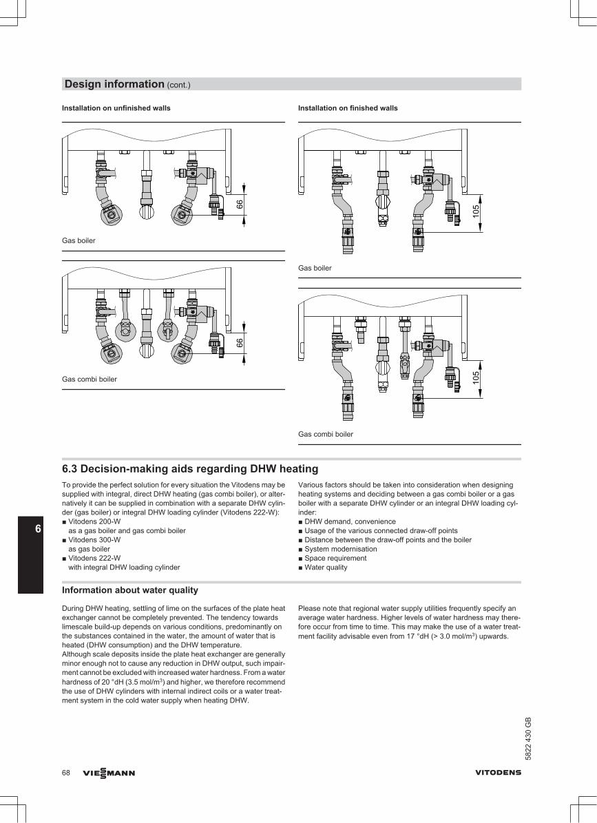
Installation on unfinished walls
66Gas boiler
66
Gas combi boiler
Installation on finished walls
105
Gas boiler
105
Gas combi boiler
6.3 Decision-making aids regarding DHW heatingTo provide the perfect solution for every situation the Vitodens may besupplied with integral, direct DHW heating (gas combi boiler), or alter-natively it can be supplied in combination with a separate DHW cylin-der (gas boiler) or integral DHW loading cylinder (Vitodens 222-W):■ Vitodens 200-W
as a gas boiler and gas combi boiler■ Vitodens 300-W
as gas boiler■ Vitodens 222-W
with integral DHW loading cylinder
Various factors should be taken into consideration when designingheating systems and deciding between a gas combi boiler or a gasboiler with a separate DHW cylinder or an integral DHW loading cyl-inder:■ DHW demand, convenience■ Usage of the various connected draw-off points■ Distance between the draw-off points and the boiler■ System modernisation■ Space requirement■ Water quality
Information about water quality
During DHW heating, settling of lime on the surfaces of the plate heatexchanger cannot be completely prevented. The tendency towardslimescale build-up depends on various conditions, predominantly onthe substances contained in the water, the amount of water that isheated (DHW consumption) and the DHW temperature. Although scale deposits inside the plate heat exchanger are generallyminor enough not to cause any reduction in DHW output, such impair-ment cannot be excluded with increased water hardness. From a waterhardness of 20 °dH (3.5 mol/m3) and higher, we therefore recommendthe use of DHW cylinders with internal indirect coils or a water treat-ment system in the cold water supply when heating DHW.
Please note that regional water supply utilities frequently specify anaverage water hardness. Higher levels of water hardness may there-fore occur from time to time. This may make the use of a water treat-ment facility advisable even from 17 °dH (> 3.0 mol/m3) upwards.
Design information (cont.)
68 VIESMANN VITODENS
658
22 4
30 G
B

Selection table Vitodens 200-W
gas combi boilerwith instantane-ous water heater
Vitodens 200-Wand Vitodens 300-W gas boiler withseparate DHW cyl-inder
Vitodens 222-Wwith integral DHWloading cylinder
DHW demand, con-venience
DHW demand for an apartment + + +DHW demand for a detached house 0 + +DHW demand for a centralised system in an apart-ment building
– + –
DHW demand for a decentralised system in an apart-ment building
+ + 0
Usage of the variousconnected draw-offpoints
One draw-off point + 0 0Several draw-off points, no simultaneous utilisation + + +Several draw-off points, simultaneous utilisation – + +
Distance betweendraw-off point andboiler
Up to 7 m (without DHW circulation pipe) + + +With DHW circulation pipe – + –
Modernisation Existing DHW cylinder – + –Replacement of an existing combi boiler + – 0
Space requirement Limited space available (installation in recesses) + 0 0Sufficient space available (installation room) + + +
Solar DHW heatingcan be connected
Connection to a dual mode DHW cylinder – + –Connection to the integral DHW cylinder – – –
+ = recommended0 = recommended under certain conditions– = not recommended
Separate DHW cylindersFor greater DHW convenience, separate DHW cylinders are alsoavailable in white in the following versions:■ Below the boiler (120 or 150 litres).■ Adjacent to the boiler (160, 200, 300 or 400 litres).Further DHW cylinders with up to 1000 litre capacity are offered inVitosilver and may also be used in accordance with the available heat-ing output.
The Vitodens 200-W and 300-W boilers are equipped at factory witha separate DHW cylinder for DHW heating. For this purpose, theVitodens 200-W and 300-W are provided with an integral divertervalve.To connect a separate DHW cylinder, always include the connectionset for the respective DHW cylinder in your order.For DHW cylinder specifications, see chapter "DHW cylinders".
Sizing cylindersDetermine the DHW cylinder size in accordance with the specific DHWdemand.Various consumer combinations may apply.If identical consumers are combined, only take into account the indi-vidual consumer, not the combination.The following summary enables an approximate sizing of the DHWcylinder:
Small households (1 to 2 occupants) Average households (3 to 4 occupants)
NoteInstead of a Vitodens 200-W or 300-W with 120 litre DHW cylinder, aVitodens 222-W can also be used.
Cylinder capacity in litres Bath 1600
to DIN 4471Bath 1700toDIN 4471
Small andsteppedbath
Large bath(1800 ×750 mm)
Shower cu-bicle withmixer tapand stand-ard showerhead
Shower cu-bicle with 1showerhead and 2side noz-zles
Washbasin Bidet
Draw-off rate in Wh 5820 6510 4890 8720 1630 4070 700 810Draw-off volume per use oravailable capacity in l
140 160 120 200 40 100 17 20
Bath 1600to DIN 4471
120 120 120 120 120120 120 150/160 120 120
Bath 1700to DIN 4471
120 120 120 120 120 120 120 120 120 120
Small and stepped bath 120 120 120 120 120 120 120 120 120 120
Large bath(1800 × 750 mm)
120 120 120 120 120 200 150/160 200 150/160 150/160
Shower cubicle with mixertap and standard showerhead
120 120 120 120 120 120 120 120120 120 120 150/160 120 120 120 120
Design information (cont.)
VITODENS VIESMANN 69
5822
430
GB
6

Bath 1600to DIN 4471
Bath 1700toDIN 4471
Small andsteppedbath
Large bath(1800 ×750 mm)
Shower cu-bicle withmixer tapand stand-ard showerhead
Shower cu-bicle with 1showerhead and 2side noz-zles
Washbasin Bidet
Shower cubicle with 1shower head and 2 sidenozzles
120 120 120 120 120 120 120150/160 150/160 200 120 120 120 120
Washbasin 120 120 120 120 120 120 120 120120 120 120 150/160 120 120 120 120
Bidet 120 120 120 120 120 120 120 120120 120 120 150/160 120 120 120 120
Example:■ Average household with 3 occupants.■ Use of a bath tub 1600 with 140 litres drawn.■ Simultaneous use of a shower cubicle with mixer tap and standard
shower head with 40 litres drawn.
The table shows that the correct DHW cylinder to DIN 4708 would havea capacity of 120 litres.
Selection tables, DHW cylindersThe DHW cylinders with a "-W" in the product name are supplied inwhite. The appliances with a "-B" or "-V" in the product name are sup-plied in Vitosilver (marked in grey in the table).
Vitodens 200-W and 300-W gas boilers, cylinder allocation
Practical cylinder allocation (cylinder capacity in litres)Rated heating output range [kW] 1.9 to 19.0 4.0 to 26.0 4.0 to 35.0Vitocell 100-W (type CUG) below the boiler 120
150120150
120150
Vitocell 100-W (type CVA) adjacent to the boiler 160200300
160200300
160200300
Vitocell 100-V (type CVA) adjacent to the boiler — — 500Vitocell 300-W (type EVA) adjacent to the boiler 160
200160200
160200
Vitocell 300-V (type EVI) adjacent to the boiler — 300500
300500
Vitocell 100-W (type CVB) adjacent, dual mode 300400
300400
300400
Vitocell 100-W (type CVU) adjacent, dual mode 400 400 400Vitocell 100-B (type CVB) adjacent, dual mode — 500 500Vitocell 300-B (type EVB) adjacent, dual mode 300 300
500300500
Vitocell 340-M (type SVK) heating water buffer cylinderwith DHW heating
705/33 705/33 705/33
Vitocell 360-M (type SVS) heating water buffer cylinderwith DHW heating
705/33 705/33 705/33
6.4 Connections on the water side
Connections on the DHW side
Vitodens 200-W gas combi boilerFor the DHW connection, connection sets for installation on finishedor unfinished walls are available as accessories. The integral instan-taneous water heater provides direct DHW heating.When using galvanised pipes, observe that the instantaneous waterheater is designed as a stainless steel plate heat exchanger with cop-per solder joints (observe the flow rule).In existing installations (modernisation projects), the risk of electrolyticcorrosion is low, since a protective layer will have formed on the insideof the pipes.
If DHW is to be drawn simultaneously from several points, we recom-mend the installation of a separate DHW cylinder in conjunction withthe gas boiler (see "Decision-making aids regarding DHW heating").From a water hardness of 20 ºdH [3.58 mmol/l] and higher, we rec-ommend the use of a water treatment system in the cold water sup-ply.
Design information (cont.)
70 VIESMANN VITODENS
658
22 4
30 G
B
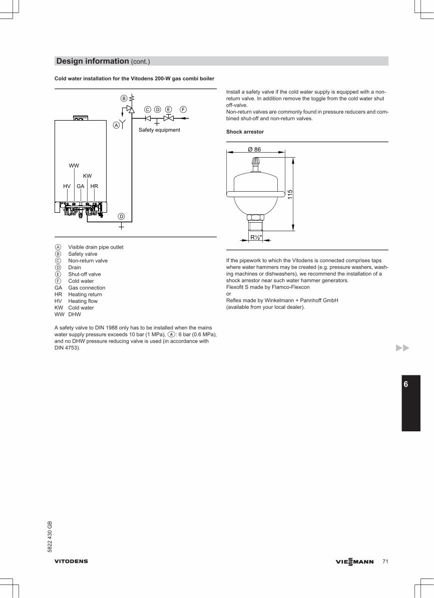
Cold water installation for the Vitodens 200-W gas combi boiler
Safety equipment
GA HR
KW
WW
HV
A Visible drain pipe outletB Safety valveC Non-return valveD DrainE Shut-off valveF Cold waterGA Gas connectionHR Heating returnHV Heating flowKW Cold waterWW DHW
A safety valve to DIN 1988 only has to be installed when the mainswater supply pressure exceeds 10 bar (1 MPa), a: 6 bar (0.6 MPa),and no DHW pressure reducing valve is used (in accordance withDIN 4753).
Install a safety valve if the cold water supply is equipped with a non-return valve. In addition remove the toggle from the cold water shutoff-valve.Non-return valves are commonly found in pressure reducers and com-bined shut-off and non-return valves.
Shock arrestor
Ø 86
115
R½"
If the pipework to which the Vitodens is connected comprises tapswhere water hammers may be created (e.g. pressure washers, wash-ing machines or dishwashers), we recommend the installation of ashock arrestor near such water hammer generators.Flexofit S made by Flamco-FlexconorReflex made by Winkelmann + Pannhoff GmbH(available from your local dealer).
Design information (cont.)
VITODENS VIESMANN 71
5822
430
GB
6

Cold water installation, separate DHW cylinder and loading cylinder of the Vitodens 222-WExample:DHW cylinder installed below (120 or 150 l) with safety assembly toDIN 1988.
C
H
B
F G KEF
D
FE L M F N D
E
P
O
A
Safety assembly to DIN 1988
A DHWB Safety valve (included in the standard delivery of the pre-plumbing
jig for the Vitodens 222-W)C Visible outlet point of the discharge pipeD Cold waterE DrainF Shut-off valveG Flow regulating valve (installation recommended)
H Pressure gauge connectionK Non-return valveL Drinking water filter M Pressure reducer to DIN 1988-2, Dec. 1988 issueN Non-return valve/pipe separatorO Standard delivery of the safety assembly offered as an accessory
(for separate DHW cylinders only)P Diaphragm expansion vessel, suitable for drinking water
Safety valveThe safety valve must be installed.
We recommend installing the safety valve above the top edge of thecylinder. This protects the valve against contamination, scaling andhigh temperatures. It also means that the DHW cylinder does not needto be drained when working on the safety valve.
Drinking water filterAccording to DIN 1988-2, a drinking water filter should be installed insystems with metal pipework. Viessmann also recommends the instal-lation of a drinking water filter when using plastic pipes to DIN 1988 toprevent contaminants entering the DHW system.
DHW circulation (only in conjunction with the Vitodens 200-W and 300-W)DHW circulation pipes increase DHW convenience and reduce waterconsumption. These advantages result from the immediate availabilityof DHW at the tap/draw-off point.However, poor thermal insulation of the DHW circulation pipe can leadto substantial heat losses.From a line length of 7 m we recommend providing appropriate ther-mal insulation for the DHW circulation in accordance with the EnergySaving Ordinance [Germany]. This specifies that the DHW circulationpipe should, in accordance with the Energy Saving Ordinance, includea circulation pump, a check valve and a time switch for shutting downDHW circulation during the night.
Design information (cont.)
72 VIESMANN VITODENS
658
22 4
30 G
B

Vitodens 200-W and 300-W
A
B
C
DHW cylinder below the boiler
A DHWB Cold waterC DHW circulation
B
C
A
DHW cylinder adjacent to the boiler
A DHWB Cold waterC DHW circulation
Vitodens 222-WThe connection of a DHW circulation pipe is not recommended.
DHW circulation for gas combi boilersDue to the low water content of plate heat exchangers, the connectionof DHW circulation lines is not recommended for gas combi boilers.
Even the low heat losses of thermally insulated DHW circulation lines(to EnEV) lead to a higher cycling frequency for the gas combi boiler(reheating).
6.5 Condensate connectionRoute the condensate drain pipe with a constant fall.The condensate from the flue system (if equipped with a drain), shouldbe routed to the public sewage system together with the boiler con-densate, either directly or (if installed) via a neutralising system (acces-sories).
NoteA pipe vent valve must be installed between the siphon and the neu-tralising system.
Vitodens 200-W and 300-W
A
B
A Drain hose (standard delivery for the Vitodens)B Drain outlet kit (accessories)
Vitodens 222-W
A
B
A Drain hose (standard delivery for the Vitodens)B Drain outlet kit (accessories)
Condensate drain and neutralisationDrain the condensate created in the condensing boiler and in the fluepipe during heating operation in accordance with appropriate regula-tions. With gas combustion, the condensate will have a pH valuebetween 4 and 5.
The Code of Practice DWA-A 251 on "Condensate from condensingboilers", which is generally based on the local waste water regulations[in Germany], determines conditions for draining condensate fromcondensing boilers into the public sewer system.
Design information (cont.)
VITODENS VIESMANN 73
5822
430
GB
6

The composition of the condensate that drains from Vitodens con-densing boilers meets the requirements specified in Code of PracticeDWA-A 251.The condensate drain pipe to the sewer connection must be freelyaccessible for inspection.It must be installed with a continuous fall and must contain a stenchtrap. Also provide a suitable facility for extracting samples.Condensate drain pipes must only be made from corrosion-resistantmaterials (e.g. reinforced hoses).Never use any zinc-plated materials or those containing copperfor pipes, connection pieces, etc. A siphon is installed in the condensate drain to prevent flue gasesescaping.Local waste water regulations and/or specific technical circumstancesmay specify designs that vary from those described in the aboveCodes of Practice.It is advisable to contact your local authority responsible for wastewater management prior to installation, to find out about local regula-tions.
Condensate from gas combustion equipment up to 200 kW com-bustion outputUp to a rated heating output of 200 kW, the condensate from a gascondensing boiler can generally be introduced into the public sewagesystem without prior neutralisation.Also ensure that your domestic drainage systems are made frommaterials that are resistant to acidic condensate.
According to the Code of Practice DWA-A 251, these materialsinclude:■ Clay pipes■ Hard PVC pipes■ PVC pipes■ PE HD pipes■ PP pipes■ ABS/ASA pipes■ Stainless steel pipes■ Borosilicate pipes
Neutralising system
A
C
B
A Condensate drainB Neutralising systemC Ventilation via the roof
The Vitodens can (if required) be supplied with a separate neutralisingsystem (accessories). Any condensate is piped to and processed inthe neutralising system.The condensate drain pipe to the sewer connection must be accessiblefor inspection. Install it with a fall and a stench trap on the sewer side,and provide a suitable facility for extracting samples.Install a condensate lifting pump if the Vitodens has been installedbelow the waste water anti-flooding level.Condensate lifting pumps are available as accessories.Since the consumption of neutralising granulate depends on the oper-ating mode of the system, carry out regular checks during the first yearof operation to determine the required top-up volume. It is feasible thatone fill may last longer than one year.
Neutralising systemPart no. 7252 666
310 DN 40
145
Condensate lifting system (accessories)
C
A
B
A Condensate inletB Condensate lifting systemC Condensate drain
Design information (cont.)
74 VIESMANN VITODENS
658
22 4
30 G
B

6.6 Hydraulic connection
General information
System designViessmann condensing boilers can generally be installed in any fullypumped hot water heating system (sealed unvented system). The circulation pump is an integral part of the appliance.Minimum system pressure 1.0 bar (0.1 MPa).The boiler water temperature is limited to 82 °C.To minimise distribution losses, we recommend sizing the heat distri-bution system to a max. flow temperature of 70 °C.For apartments with less than 80 m2 living space or for low energyhouses with low heat demand we recommend, due to the immediatecapturing of the room-influencing factors, using the Vitodens with aconstant temperature control unit in conjunction with the Vitotrol 100.To reduce burner cycling in low energy houses with a correspondinglylow heat demand, we recommend the use of a low loss header or aVitodens 300-W with 1.9 to 11 kW.
Chemical anti-corrosion agentsIn correctly installed and operated sealed unvented heating systemscorrosion is generally avoided.Never use chemical anti-corrosion additives.Some manufacturers of plastic pipes recommend the use of chemicaladditives. In such cases, only use anti-corrosion agents offered by theheating trade that have been approved for boilers with DHW heatingvia single-walled heat exchangers (instantaneous water heater orDHW cylinder).For this, observe the VDI Directive 2035 [or local regulations].
Heating circuitsFor heating systems with plastic pipes, we recommend the use ofimpermeable pipes to prevent the diffusion of oxygen through the pipewalls.Provide system separation in heating systems with plastic pipes(DIN 4726) that are permeable to oxygen. We supply a separate heatexchanger for this purpose.Install a dirt separator in underfloor heating systems; see theViessmann Vitoset pricelist.Underfloor heating systems and heating circuits with very large watercontent (>15 l/kW) should be connected to the boiler, even if a con-densing boiler, via a 3-way mixer. See technical guide "Control ofunderfloor heating systems" or the relevant sample applications.Install a temperature limiter in the flow of the underfloor heating circuitto restrict the maximum temperature. Observe the requirements ofDIN 18560-2 [or local regulations].
Plastic pipework for radiatorsWe also recommend the installation of a temperature limiter to restrictthe maximum temperature for plastic pipes in heating circuits withradiators.
Attic heating centreThe installation of a low water indicator specified as compulsory byDVGW is not required when installing the Vitodens in an attic.The Vitodens condensing boilers are protected against water shortagein accordance with EN 12828.
Safety valveA safety valve in accordance with TRD 721 is integrated in theVitodens (opening pressure 3 bar (0.3 MPa)).Route the discharge pipe in accordance with EN 12828 into a drainoutlet (drain outlet kit available as an accessory). The drain outletincorporates a siphon as a stench trap.
Low water indicatorAccording to EN 12828, a low water indicator can be omitted for boilersup to 300 kW, as long as heating can be reliably prevented when thereis a water shortage.
Viessmann Vitodens boilers are equipped with a low water indicator(boil-dry protection). Tests have verified that the burner will be auto-matically switched off in the event of water shortage due to a leak inthe heating system and simultaneous burner operation, before theboiler or the flue system reaches unacceptably high temperatures.
Water quality/Frost protectionUnsuitable fill and top-up water increases the level of deposits andcorrosion and may lead to the boiler damage.Observe VDI 2035 regarding quality and amount of heating water, incl.fill and top-up water.■ Flush the heating system thoroughly before filling.■ Only fill with water of potable quality.■ Fill and top-up water with a water hardness in excess of the following
values must be softened, e.g. with the small softening system forheating water (see the Viessmann Vitoset pricelist):
Total permissible hardness of the fill and top-up waterTotal heatingoutput
Specific system volume
kW < 20 l/kW ≥ 20 l/kW to< 50 l/kW
≥ 50 l/kW
≤ 50 ≤ 3.0 mol/m3
(16.8 °dH)≤ 2.0 mol/m3
(11.2 °dH)< 0.02 mol/m3
(0.11 °dH)> 50 to ≤ 200 ≤ 2.0 mol/m3
(11.2 °dH)≤ 1.5 mol/m3
(8.4 °dH)< 0.02 mol/m3
(0.11 °dH)
■ For systems with a specific system volume in excess of 20 litres/kWheating output, use the output of the smallest boiler in multi boilersystems.
■ An antifreeze additive suitable for heating systems can be added tothe fill water. The antifreeze manufacturer must verify its suitability,otherwise damage to gaskets and diaphragms may occur, as wellas noise during heating operation. Viessmann accepts no liability forany resulting damage or consequential losses.
When engineering the system, observe the following:■ Install shut-off valves in the different sections. This prevents the
need for draining all of the heating water in the case of repairs orsystem expansion.
■ In systems > 50 kW, install a water meter to record the volume ofthe fill and top-up water. Record the amount of water filled into thesystem and the water hardness.
Operating information:■ Commission the system step by step, starting with the lowest boiler
output and a high heating water flow rate. This prevents a localisedconcentration of limescale deposits on the boiler heating surfaces.
■ In multi boiler systems, start all boilers simultaneously to prevent theentire limescale deposit settling in the heat transfer area of just oneboiler.
■ During extension or repair work, only drain the necessary pipeworksections.
■ Where water treatment is required, treat even the first fill of the heat-ing system prior to commissioning. This also applies to any subse-quent filling, e.g. after repairs or after system expansion, and for allamounts of top-up water.
■ Check, clean and activate filters, dirt traps and other blow-down orseparating facilities in the heating water circuit more frequently aftercommissioning or new installations; later on do so subject to require-ments in line with the water treatment applied (e.g. water softening).
Modernising existing systemsThird party appliance adaptors are available as accessories for theVitodens 200-W and 300-W.
Design information (cont.)
VITODENS VIESMANN 75
5822
430
GB
6

This enables existing hydraulic connections for wall mounted boilertypes Thermobloc-VC/-VCW, Cerastar-ZR/-ZWR and Ceramini to beadapted to suit the Vitodens (see page 61).
Installation examplesFor installation examples for the Vitodens 200-W, 222-W and 300-W,see "System examples".Never install the Vitodens 222-W in dual mode systems with solid fuelboilers.
Expansion vesselsIn accordance with EN 12828, water heating systems must be equip-ped with a pressure expansion vessel.■ An expansion vessel is integrated into the following Vitodens boilers:
– Vitodens 200-W to 35 kW– Vitodens 222-W– Vitodens 300-W, 11 and 19 kW
■ For the Vitodens 300-W, 26 and 35 kW a mounting frame withexpansion vessel and valves is available as an accessory (seepage 45).
Determine the size of the expansion vessel to be installed in accord-ance with EN 12828.If the integral expansion vessel or that supplied as an accessory isinadequate, install a suitably sized expansion vessel on site.
Low loss header
Application
Design rules for system hydraulics:■ When balancing the low loss header, adjust the flow rate on the
equipment side to approx. 10 to 30 % below the flow rate on thesystem side (reducing the return temperature).
■ The low loss header should be sized for the max. flow rate whichmay occur in the overall system.
The low loss header separates the heat source (boiler circuit) from thedownstream heating circuits.Install a low loss header if the max. flow rate of an individual design isgreater than the corresponding value shown in the "Specification"table. For installation designs in conjunction with low loss headers, see"System examples".
Boiler circuitThe circulation pump in the Vitodens must be able to supply therequired water volume against the (generally low) pressure drop of theboiler circuit; the pressure drop of the low loss header is negligible.Subject to the water volume circulating in the boiler circuit, the respec-tive residual head may be determined for sizing the internal pipe diam-eters using the pump diagrams; alternatively the variable speed pumpfor the Vitodens 300-W can be adjusted accordingly.
Heating circuitThe heating circuit pumps to be installed on site must be able to deliverthe water volume in the heating circuits against their pressure drop,and must be sized accordingly.
Principle of operation
T1 T3
T2 T4
VsecondaryVprimary
Vprimary Heating water volume in the boiler circuit (approx. 10 -30 % less than Vsecondary)
Vsecondary Heating water volume, heating circuitT1 Flow temperature, boiler circuitT2 Return temperature, boiler circuitT3 Flow temperature, heating circuitT4 Return temperature, heating circuitQprimary Amount of heat supplied by the boilerQsecondary Amount of heat transferred by the heating circuit
Vprimary < Vsecondary T1 > T3 T2 ≃ T4 Qprimary = Qsecondary
NoteSuitable thermometers in the flow and return of the low loss headermake adjustments easier.
Low loss header in conjunction with DiviconFor further details, see the technical guide to the Vitodens 200-W, 45to 150 kW.
Max. flow ratein m3/h
Low loss header– R ¾ 4.5– R 1 4.5– R 1¼ 7.5Divicon heating circuit distributor– R ¾ 1.0– R 1 1.5– R 1¼ 2.5
Design information (cont.)
76 VIESMANN VITODENS
658
22 4
30 G
B

HRHV
120 120599
267 42
881
6
C
B
A
180
HR Heating returnHV Heating flowA Divicon heating circuit distributorB ManifoldC Low loss header
HRHV
120 120790
267 42
881
6
120 180 180
HR Heating returnHV Heating flow
Low loss header from the Vitoset rangeSee "Vitoset" pricelist
ed
c
ba
HV
HR
KV
KR
HR Heating returnHV Heating flowKR Boiler returnKV Boiler flow
Flow rate Max.
m3/h 4 4 8 10 18
Connections - Female thread Rp 1 - Male thread R 1¼ 2 - Flange DN 65 80Di-men-sions
a mm 500 500 800 1400 1450
b mm 360 360 650 1000 1000 c mm 270 270 550 1000 1000 d mm 80 80 120 160 200 e mm 50 50 80 80 120
6.7 Intended useThe appliance is only intended to be installed and operated in sealedunvented heating systems that comply with EN 12828, with due atten-tion paid to the associated installation, service and operating instruc-tions. It is only designed for the heating of water that is of potable waterquality.
Intended usage presupposes that a fixed installation in conjunctionwith permissible, system-specific components has been carried out.
Commercial or industrial usage for a purpose other than heating thebuilding or DHW does not comply with regulations.
Any usage beyond this must be approved by the manufacturer for theindividual case.
Incorrect usage or operation of the appliance (e.g. the appliance beingopened by the system user) is prohibited and results in an exclusionof liability. Incorrect usage also occurs if the components in the heatingsystem are modified from their intended function (e.g. if the flue gasand ventilation air paths are sealed).
Design information (cont.)
VITODENS VIESMANN 77
5822
430
GB
6

7.1 Vitotronic 100, type HC1B, for constant temperature operation
Layout and functions
Modular structureThe control unit is integrated into the boiler.The control unit comprises a standard unit, electronics modules and aprogramming unit.
Standard unit:■ ON/OFF switch■ Optolink laptop interface■ Operating and fault indicators■ Reset button■ Fuses
48°C
s A
Programming unit:■ Easy operation through display with large font and depiction with
good contrast■ Removable programming unit; can be mounted as option on the wall
with separate accessory■ Menu prompts through pictograms■ Operating keys for:
– Navigation– Confirmation– Settings/menu
■ Settings:– Boiler water temperature– DHW temperature– Operating program– Codes– Actuator tests– Test mode
■ Displaying:– Boiler water temperature– DHW temperature– Operating data– Diagnostic details– Fault messages
Functions■ Electronic boiler control unit for operation at a constant boiler water
temperature■ Room temperature-dependent operation requires a Vitotrol 100,
type UTA, UTDB or UTDB-RF (according to EnEV [Germany])■ Heating system frost protection■ Anti-seizing pump protection■ Integral diagnostic system■ Cylinder thermostat with priority■ Control of solar DHW heating and central heating backup in con-
junction with the solar control module, type SM1■ Auxiliary function for DHW heating (short-term heating to a higher
temperature)■ Maintenance display■ External starting and blocking (in conjunction with extension EA1)
Control characteristicsPI characteristics with modulating output.
Setting the heating programsThe heating system frost protection (see frost protection function)applies to all heating programs.The following heating programs can be selected:■ Heating and DHW■ Only DHW■ Standby mode
Frost protection functionThe frost protection function is active in all heating programs.The burner is switched ON at a boiler water temperature of 5 ºC andwill be switched OFF again at a boiler water temperature of 20 ºC.The circulation pump will be switched ON simultaneously with theburner and switched OFF after a delay.The DHW cylinder will be heated to approx. 20 ºC.To protect the system against frost, the circulation pump may be star-ted at certain intervals (up to 24 times per day) for periods of approx.10 minutes.
Summer modeOperating program "w" The burner starts only when the cylinder needs reheating or whenDHW is drawn from a combi boiler.
Boiler water temperature sensorThe boiler water temperature sensor is connected to the control unitand built into the boiler.
SpecificationSensor type Viessmann NTC, 10 kΩ at
25 °CPermissible ambient temperature – during operation 0 to +130 °C– during storage and transport –20 to +70 °C
Cylinder temperature sensorStandard delivery for:■ Connection set for DHW cylinders below the boiler (120 or 150 litres)
(order separately)■ Connection set for DHW cylinders adjacent to the boiler (160 to 400
litres) or alternative DHW cylinders (order separately)
SpecificationCable length 3.75 m, fully wiredIP rating IP 32Sensor type Viessmann NTC 10 kΩ at
25 °CPermissible ambient temperature – during operation 0 to +90 °C– during storage and transport –20 to +70 °C
Cylinder temperature sensor (Vitodens 222-W) and outlet tem-perature sensorThese sensors are connected to the control unit and built into the boileror cylinder.
SpecificationIP rating IP 32Sensor type Viessmann NTC 10 kΩ at
25 °CPermissible ambient temperature – during operation 0 to +90 °C– during storage and transport –20 to +70 °C
Control units
78 VIESMANN VITODENS
7
5822
430
GB

Specification Vitotronic 100, type HC1B
Rated voltage 230 V~Rated frequency 50 HzRated current 6 ASafety category IMode of operation Type 1 B to EN 60730-1Permissible ambi-ent temperature
– during operation 0 to +40 °CInstallation in living spaces or boiler rooms(standard ambient conditions)
– during storageand transport –20 to +65 °C
Electronic tempera-ture limiter setting(heating mode) 82 °C (no change possible)DHW temperaturesetting range
– gas combi boilers 10 to 57 °C– gas system boil-
ers 10 to 68 °C– Vitodens 222-W 10 to 63 °C
7.2 Vitotronic 200, type HO1B, for weather-compensated operationIn conjunction with the Vitodens 200-W and 222-W.Layout and functions
Modular structureThe control unit is integrated into the boiler.The control unit comprises a standard unit, electronics modules and aprogramming unit.
Standard unit:■ ON/OFF switch■ Optolink laptop interface■ Operating and fault indicators■ Reset button■ Fuses
48 °CBoiler temperature
HC1
14°C 21°C
Programming unit:■ Easy operation through:
– Plain text display with graphic ability– Large font and black/white depiction for good contrast– Context-sensitive help– Removable programming unit; can be mounted as option on the
wall with separate accessory■ With digital time switch■ Control keys for:
– Navigation– Confirmation– Help and additional information– Menu
■ Setting the:– Room temperature– Reduced room temperature– DHW temperature– Operating program– Time programs for central heating, DHW heating and DHW circu-
lation– Economy mode– Party mode– Holiday program– Heating curves– Codes– Actuator tests– Test mode
■ Displaying:– Boiler water temperature– DHW temperature– Operating data– Diagnostic details– Fault messages
■ Available languages:– Deutsch– Bulgarian– Czech– Danish– English– Spanish– Estonian– French– Croatian– Italian– Latvian– Lithuanian– Hungarian– Dutch– Polish– Russian– Romanian– Slovenian– Finnish– Swedish– Turkish
Functions■ Weather-compensated control of the boiler water and/or flow tem-
perature■ Control of one heating circuit without mixer and two heating circuits
with mixer■ Electronic maximum and minimum temperature limit■ Demand-dependent heating circuit pump and burner shutdown con-
trol■ Adjustment of a variable heating limit
Control units (cont.)
VITODENS VIESMANN 79
5822
430
GB
7

■ Pump anti-seizing protection■ Frost protection monitoring for the heating system■ Integral diagnostic system■ Maintenance display■ Cylinder temperature controller with priority control■ In conjunction with solar control module, type SM1:
– Control unit for solar DHW heating and central heating backup– Graphic display of solar yield
■ Auxiliary function for DHW heating (short-term heating to a highertemperature)
■ Screed drying program■ External starting and blocking (in conjunction with extension EA1)
The requirements of DIN EN 12831 for calculating the heat load aremet. To reduce the heat-up output, the reduced room temperature willbe raised in case of low outside temperatures. The flow temperaturewill be raised for a limited time to reduce the heat-up time after a set-back phase.According to the Energy Saving Ordinance [Germany], the tempera-ture in each room must be individually controlled, e.g. through ther-mostatic radiator valves.
Control characteristicsPI characteristics with modulating output.
Time switchDigital time switch (integrated into the programming unit)■ Individual day and seven-day program■ Automatic summer/wintertime changeover■ Automatic function for DHW heating and DHW circulation pump■ Time, day and standard switching times for central heating, DHW
heating and the DHW circulation pump are factory-set■ Switching times are individually programmable, i.e. up to four switch-
ing periods per dayShortest switching interval: 10 minutesPower reserve: 14 days
Setting the operating programsThe heating system frost protection (see frost protection function)applies to all heating programs.The following heating programs can be selected:■ Heating and DHW■ Only DHW■ Standby modeExternal heating program changeover in conjunction with EA1 exten-sion.
Frost protection function■ The frost protection function will be started when the outside tem-
perature drops below approx. +1 °C.With frost protection, the heating circuit pump is switched ON andthe boiler water is maintained at a lower temperature of approx.20 °C.The DHW cylinder will be heated to approx. 20°C.
■ The frost protection function will be stopped when the outside tem-perature rises above approx. +3 °C.
Summer modeOperating program "w"The burner only starts when the cylinder needs reheating or whenDHW is drawn from a gas combi boiler.
Adjusting the heating curves (slope and level)The Vitotronic 200 controls the boiler water temperature (= flow tem-perature of the heating circuit without mixer) and the flow temperatureof the heating circuits with mixer (in conjunction with the extension kitfor one heating circuit with mixer) in weather-compensated mode. Theboiler water temperature is automatically boosted by between 0 and40 K higher than the currently required set flow temperature (deliveredcondition 8 K).
The flow temperature required to reach a specific room temperaturedepends on the heating system and the thermal insulation of the build-ing to be heated.Adjusting the heating curves matches the boiler water temperature andthe flow temperature to these operating conditions.Heating curves:The upper boiler water temperature is limited by the temperature limiterand the temperature set at the electronic maximum thermostat.The flow temperature cannot exceed the boiler water temperature.
3.2
3.4
Boile
r wat
er o
rflo
w te
mpe
ratu
re in
°C
Outside temperature in °C
Heating curve slope
3.0
2.8
2.2
2.4
2.0
1.6
1.41.21.00.80.60.40.2
9080706050403020
-20-15-10-505101520
1.8
2.6
-30-25
Heating systems with low loss headerWhen using hydraulic separation (low loss header), connect a tem-perature sensor for use in the low loss header.
Boiler water temperature sensorThe boiler water temperature sensor is connected to the control unitand built into the boiler.
SpecificationSensor type Viessmann NTC, 10 kΩ at
25 °CPermissible ambient temperature – during operation 0 to +130 °C– during storage and transport –20 to +70 °C
Cylinder temperature sensor (Vitodens 200-W and 300-W)Standard delivery for:■ Connection set for DHW cylinders below the boiler (120 or 150 litre)
(order separately)■ Connection set for DHW cylinders adjacent to the boiler (160 to
400 litres) or alternative DHW cylinders (order separately)
SpecificationCable length 3.75 m, fully wiredIP rating IP 32Sensor type Viessmann NTC 10 kΩ at
25 °CPermissible ambient temperature – during operation 0 to +90 °C– during storage and transport –20 to +70 °C
Cylinder temperature sensor (Vitodens 222-W) and outlet tem-perature sensorThese sensors are connected to the control unit and built into the boileror cylinder.
SpecificationIP rating IP 32Sensor type Viessmann NTC 10 kΩ at
25 °CPermissible ambient temperature – during operation 0 to +90 °C– during storage and transport –20 to +70 °C
Control units (cont.)
80 VIESMANN VITODENS
7
5822
430
GB

Outside temperature sensorInstallation site:■ North or north-western wall of the building■ 2 to 2.5 m above the ground, for multi storey buildings in the upper
half of the second floorConnection:■ 2-core lead, length max. 35 m with a cross-section of 1.5 mm2 (cop-
per).■ Never route this lead immediately next to 230/400 V cables
41 66
80
SpecificationIP rating IP 43 to EN 60529
ensure through appropriatedesign/installation
Sensor type Viessmann NTC 10 kΩ, at25 °C
Permissible ambient temperature dur-ing operation, storage and transport −40 to +70 °C
Specification Vitotronic 200, type HO1B
Rated voltage 230 V~Rated frequency 50 HzRated current 6 ASafety category IPermissible ambienttemperature
– during operation 0 to +40 °CInstallation in living spaces or boiler rooms(standard ambient conditions)
– during storage andtransport –20 to +65 °C
Electronic temperaturelimiter setting (heatingmode) 82 °C (no change possible)
DHW temperature set-ting range
– gas combi boilers 10 to 57 °C– gas system boilers 10 to 68 °C– Vitodens 222-W 10 to 63 °CHeating curve settingrange
Slope 0.2 to 3.5Level –13 to 40 K
7.3 Vitotronic 200 RF, type HO1C, for weather-compensated operationIn conjunction with Vitodens 300-W.Design and functions
Modular designThe control unit is integrated into the boiler.The control unit comprises a standard unit, electronics modules and aprogramming unit.
Standard unit:■ ON/OFF switch■ LON communication module
For remote control of the heating system via the Vitotrol app (iOS4.3 / 5 operating system) in conjunction with Vitocom 100 LAN1, forexample.
■ Optolink laptop interface■ Operating and fault indicators■ Reset button■ Fuses
48 °CBoiler temperature
HC1
14°C 21°C
Programming unit:■ Easy operation thanks to:
– Plain text display with graphic ability– Large font and black/white depiction for good contrast– Context-sensitive help– Removable programming unit; can optionally be mounted on the
wall with separate accessory■ With digital time switch
Control units (cont.)
VITODENS VIESMANN 81
5822
430
GB
7

■ With radio interface for communication with the following:– Wireless outside temperature sensor– Vitotrol 200 RF– Vitotrol 300 RF– Vitocomfort 200– Wireless repeater
■ Operating keys for:– Navigation– Confirmation– Help and additional information– Menu
■ Adjustment of:– Room temperature– Reduced room temperature– DHW temperature– Heating program– Time programs for central heating, DHW heating and DHW circu-
lation– Economy mode– Party mode– Holiday program– Heating curves– Codes– Actuator tests– Test mode
■ Display of:– Boiler water temperature– DHW temperature– Operating data– Diagnostic details– Fault messages
■ Available languages:– English– Bulgarian– Czech– Danish– English– Spanish– Estonian– French– Croatian– Italian– Latvian– Lithuanian– Hungarian– Dutch– Polish– Russian– Romanian– Slovenian– Finnish– Swedish– Turkish
Functions■ Weather-compensated control of the boiler water and/or flow tem-
perature■ Control of one heating circuit without mixer and two heating circuits
with mixer■ Electronic maximum and minimum temperature limit■ Demand-dependent heating circuit pump and burner shutdown con-
trol■ Setting a variable heating limit■ Pump anti-seizing protection■ Frost protection monitoring for the heating system■ Integral diagnostic system■ Flow rate monitoring■ Hydraulic balancing of a heating circuit without mixer and without low
loss header using Vitosoft 300 SID1. In conjunction with service casefor automatic hydraulic balancing (accessories) and the flow ratesensor installed in the Vitodens.
■ Communication via radio interface■ Maintenance display■ Cylinder temperature controller with priority control■ In conjunction with solar control module, type SM1:
– Control of solar DHW heating and central heating backup– Graphic illustration of the solar energy yield
■ Auxiliary function for DHW heating (short-term heating to a highertemperature)
■ Screed drying program■ Option to connect DHW circulation pump to the control unit■ External starting and blocking (in conjunction with extension EA1)■ Capable of communicating via integral LON communication module
The requirements of DIN EN 12831 for calculating the heat load aremet. To reduce the heat-up output, the reduced room temperature willbe raised in case of low outside temperatures. The flow temperaturewill be raised for a limited time to reduce the heat-up time after a set-back phase.According to the Energy Saving Ordinance [Germany], the tempera-ture in each room must be individually controlled, e.g. through ther-mostatic radiator valves.
Control characteristicsPI characteristics with modulating output.
Time switchDigital time switch (integrated into the programming unit)■ Individual day and seven-day program■ Automatic summer/wintertime changeover■ Automatic function for DHW heating and DHW circulation pump■ Time, day and standard switching times for central heating, DHW
heating and the DHW circulation pump are factory-set■ Switching times are individually programmable, i.e. up to four switch-
ing periods per dayShortest switching interval: 10 minutesPower reserve: 14 days
Setting the operating programsThe heating system frost protection (see frost protection function)applies to all heating programs.The following heating programs can be selected:■ Heating and DHW■ Only DHW■ Standby modeExternal heating program changeover in conjunction with EA1 exten-sion.
Frost protection function■ The frost protection function will be started when the outside tem-
perature drops below approx. +1 °C.With frost protection, the heating circuit pump is switched ON andthe boiler water is maintained at a lower temperature of approx.20 °C.The DHW cylinder will be heated to approx. 20°C.
■ The frost protection function will be stopped when the outside tem-perature rises above approx. +3 °C.
Summer modeOperating program "w"The burner only starts when the cylinder needs reheating or whenDHW is drawn from a combi boiler.
Adjusting the heating curves (slope and level)The Vitotronic 200 controls the boiler water temperature (= flow tem-perature of the heating circuit without mixer) and the flow temperatureof the heating circuits with mixer (in conjunction with the extension kitfor one heating circuit with mixer) in weather-compensated mode. Theboiler water temperature is automatically boosted by between 0 and40 K higher than the currently required set flow temperature (deliveredcondition 8 K).
Control units (cont.)
82 VIESMANN VITODENS
7
5822
430
GB

The flow temperature required to reach a specific room temperaturedepends on the heating system and the thermal insulation of the build-ing to be heated.Adjusting the heating curves matches the boiler water temperature andthe flow temperature to these operating conditions.Heating curves:The upper boiler water temperature is limited by the temperature limiterand the temperature set at the electronic maximum thermostat.The flow temperature cannot exceed the boiler water temperature.
3.2
3.4
Boile
r wat
er o
rflo
w te
mpe
ratu
re in
°C
Outside temperature in °C
Heating curve slope
3.0
2.8
2.2
2.4
2.0
1.6
1.41.21.00.80.60.40.2
9080706050403020
-20-15-10-505101520
1.8
2.6
-30-25
Heating systems with low loss headerWhen using hydraulic separation (low loss header), connect a tem-perature sensor for use in the low loss header.
Boiler water temperature sensorThe boiler water temperature sensor is connected to the control unitand built into the boiler.
SpecificationSensor type Viessmann NTC, 10 kΩ at
25 °CPermissible ambient temperature – during operation 0 to +130 °C– during storage and transport –20 to +70 °C
Cylinder temperature sensorStandard delivery for:■ Connection set for DHW cylinders below the boiler (120 or 150 litre)
(order separately)■ Connection set for DHW cylinders adjacent to the boiler (160 to
400 litres) or alternative DHW cylinders (order separately)
SpecificationCable length 3.75 m, fully wiredIP rating IP 32Sensor type Viessmann NTC 10 kΩ at
25 °CPermissible ambient temperature – during operation 0 to +90 °C– during storage and transport –20 to +70 °C
Information regarding outside temperature sensorThe Vitodens is supplied, subject to order, with a wireless outsidetemperature sensor or a hardwired outside temperature sensor:
Wireless outside temperature sensorWireless subscriberWireless, light-activated outside temperature sensor with integral wire-less transmitter for operation with the wireless base station and theVitotronic control unit.
Installation location:■ North or north-west facing wall of the building■ 2 to 2.5 m above the ground, for multi storey buildings in the upper
half of the second floor
41 66
80
SpecificationPower supply via PV cells and energy storeRadio frequency 868.3 MHzWireless range See "Wireless accessories"
technical guideIP rating IP 43 to EN 60529
Ensure through design/in-stallation
Permissible ambient temperature dur-ing operation, storage and transport −40 to +60 °C
Outside temperature sensorInstallation site:■ North or north-western wall of the building■ 2 to 2.5 m above the ground, for multi storey buildings in the upper
half of the second floorConnection:■ 2-core lead, length max. 35 m with a cross-section of 1.5 mm2 (cop-
per).■ Never route this lead immediately next to 230/400 V cables
41 66
80
SpecificationIP rating IP 43 to EN 60529
ensure through appropriatedesign/installation
Sensor type Viessmann NTC 10 kΩ, at25 °C
Permissible ambient temperature dur-ing operation, storage and transport −40 to +70 °C
LON communication modulePCB for exchanging data with the Vitotronic 200-H, Vitocom 100, typeLAN1, Vitocom 200 and for connecting to a higher level building man-agement system.
Control units (cont.)
VITODENS VIESMANN 83
5822
430
GB
7

Specification Vitotronic 200 RF, type HO1C
Rated voltage 230 V~Rated frequency 50 HzRated current 6 ASafety category IPermissible ambienttemperature
– during operation 0 to +40 °CInstallation in living spaces or boiler rooms(standard ambient conditions)
– during storage andtransport –20 to +65 °C
Electronic temperaturelimiter setting (heatingmode) 82 °C (no change possible)
DHW temperature set-ting range
– gas combi boilers 10 to 57 °C– gas system boilers 10 to 68 °C– Vitodens 222-W 10 to 63 °CHeating curve settingrange
Slope 0.2 to 3.5Level –13 to 40 KRadio frequency 868.3 MHzWireless range See "Wireless accessories" technical guide
7.4 Vitotronic accessories
Allocation to control unit types
Vitotronic 100 200 200 RFType HC1B HO1B HO1CAccessoriesVitotrol 100, type UTA x Vitotrol 100, type UTDB x External extension H4 x Vitotrol 100, type UTDB-RF x Vitotrol 200A x xVitotrol 300A x xVitocomfort 200 x xVitotrol 200 RF x xVitotrol 300 RF x xWireless base station x Wireless outside temperature sensor x Wireless repeater x xRoom temperature sensor for Vitotrol 300A x xImmersion temperature sensor x x xMounting base for programming unit x x xRadio clock receiver x xKM BUS distributor x x xExtension kit for one heating circuit with mixer with integral mixer motor x xExtension kit for one heating circuit with mixer with separate mixer motor x xImmersion thermostat for underfloor heating systems x xContact thermostat for underfloor heating systems x xSolar control module SM1 x x xTemperature sensor for solar control module SM1 x x xInternal extension H1 x x xInternal extension H2 x x xExtension AM1 x x xExtension EA1 x x xVitocom 100 LAN1 without communication module xVitocom 100 LAN1 with communication module x Vitocom 100 GSM2 x x xVitocom 200 GP3, LAN2 x xLON cable x xLON coupling x xLON plug-in connector x xLON socket x xTerminator xLON communication module x
Control units (cont.)
84 VIESMANN VITODENS
7
5822
430
GB

Vitotrol 100, type UTA
Part no. 7170 149
Room thermostat■ With switching output (two-point output)■ With analogue time switch■ With adjustable individual day program■ Standard switching times are factory-set (individually programma-
ble)■ Shortest switching interval 15 minutes
Install the Vitotrol 100 in the main living room on an internal wall oppo-site radiators, but not inside shelf units, recesses, immediately by adoor or a heat source (e.g. direct sunlight, fireplace, TV set, etc.).Control unit connection:3-core cable with a cross-section of 1.5 mm2 (without green/yellow) for230 V~.
150
34
90
SpecificationRated voltage 230 V/50 HzRated breaking capacity of the con-tact 6(1) A 250 V~IP rating IP 20 to EN 60529
ensure through appropriatedesign/installation
Permissible ambient temperature – during operation 0 to +40 °C– during storage and transport –20 to +60 °CSet value setting range for standardmode and reduced mode 10 to 30 °CSet room temperature in standbymode 6 °C
Vitotrol 100, type UTDB
Part no. Z007 691
Room temperature controller■ With switching output (two-point output)■ With digital time switch■ With individual and 7-day programs■ Operation with user prompts:
– 3 preselected time programs, individually adjustable– Constant manual mode with adjustable set room temperature– Frost protection mode– Holiday program
■ With selector keys for party and economy mode
Installation in the main living room on an internal wall opposite radia-tors. Never install inside shelving units, in recesses, or immediately bya door or heat source (e.g. direct sunlight, fireplace, TV set, etc.).Operation independent of mains power supply (two 1.5 V round alka-line batteries, type LR6/AA, which run for approx.1.5 years).Control unit connection:2-core lead with a cross-section of 0.75 mm2 for 230 V~.
29
130
80
SpecificationRated voltage 3 V–
Battery LR6/AARated breaking capacity of the float-ing contact
– max. 6(1) A, 230 V~– min. 1 mA, 5 V–IP rating IP 20 to EN 60529
ensure through appropriatedesign/installation
Function RS Type 1B to EN 60730-1Permissible ambient temperature – during operation 0 to +40 °C– during storage and transport –25 to +65 °CSetting range – Comfort temperature 10 to 40 °C– Setback temperature 10 to 40 °C– Frost protection temperature 5 °CPower reserve during batterychange 3 min
Control units (cont.)
VITODENS VIESMANN 85
5822
430
GB
7

External extension H4
Part no. 7197 227Connection extension for connecting the Vitotrol 100, type UTDB or24 V clock thermostats via a LV cable.With cable (0.5 m long) and plug for the connection to theVitotronic 100.
72 130
45
SpecificationRated voltage 230 V~Output voltage 24 V~Rated frequency 50 HzPower consumption 2.5 WLoad 24 V~ (max.) 10 WProtection class IIP rating IP 41Permissible ambient temperature – during operation 0 to +40 °C
Installation in living spaces orboiler rooms (standard ambi-ent conditions)
– during storage and transport -20 to +65 °C
Vitotrol 100, type UTDB-RF
Part no. Z007 692
Room temperature controller with integral wireless transmitter and onereceiver■ With digital time switch■ With individual and 7-day programs■ Operation with user prompts:
– 3 preselected time programs, individually adjustable– Constant manual mode with adjustable set room temperature– Frost protection mode– Holiday program
■ With selector keys for party and economy mode
Installation in the main living room on an internal wall opposite radia-tors. Never install inside shelving units, in recesses, or immediately bya door or heat source (e.g. direct sunlight, fireplace, TV set, etc.).Room temperature controller operation independent of mains powersupply (two 1.5 V round alkaline batteries, type LR6/AA, which run forapprox.1.5 years).Receiver with relay state indication.
Connection of the receiver to the control unit (subject to control unittype):■ 4-core cable with a cross-section of 1.5 mm2 for 230 V~
or■ 3-core cable without green/yellow core for 230 V~
or■ 2-core lead with a cross-section of 0.75 mm2 for LV for the connec-
tion to the control unit, plus an additional 2-core cable for the230 V~ power supply
130
29
13030
8080
Specification, room temperature controllerRated voltage 3 V–Transmission frequency 868 MHzTransmission < 10 mWRange Approx. 25 to 30 m inside
buildings, subject to construc-tion
IP rating IP 20 to EN 60529ensure through appropriatedesign/installation
Function RS Type 1B to EN 60730-1Permissible ambient temperature – during operation 0 to +40 °C– during storage and transport –25 to +65 °CSetting range – Comfort temperature 10 to 40 °C– Setback temperature 10 to 40 °C– Frost protection temperature 5 °CPower reserve during batterychange 3 min
Specification, receiverOperating voltage 230 V~ ± 10 % 50 HzRated breaking capacity of the float-ing contact
– max. 6(1) A, 230 V~– min. 1 mA, 5 V–
Control units (cont.)
86 VIESMANN VITODENS
7
5822
430
GB

IP rating IP 20 to EN 60529ensure through appropriatedesign/installation
Safety category II to EN 60730-1 subject to cor-rect installation
Permissible ambient temperature – during operation 0 to +40 °C– during storage and transport –25 to +65 °C
Notes regarding room temperature hook-up (RS function) for remote control unitsNever activate the RS function for underfloor heating circuits (iner-tia).
In heating systems with a heating circuit without mixer and heatingcircuits with mixer, the RS function must only affect the heating circuitwith mixer.
Information on the Vitotrol 200A and Vitotrol 300AOne Vitotrol 200A or one Vitotrol 300A can be used for every heatingcircuit in a heating system.The Vitotrol 200A can regulate one heating circuit; the Vitotrol 300Aup to three heating circuits.Up to two remote controls may be connected to the control unit.
NoteHardwired remote control units cannot be combined with the wirelessbase station.
Vitotrol 200A
Part no. Z008 341KM BUS subscriber■ Indications:
– Room temperature– Outside temperature– Operating condition
■ Settings:– Set room temperature for standard mode (day temperature)
NoteThe set room temperature for reduced mode (night temperature)is set at the control unit.
– Operating program■ Party and economy mode can be enabled via keys■ Integral room temperature sensor for room temperature hook-up
(only for one heating circuit with mixer)
Installation site:■ Weather-compensated mode:
Installation anywhere in the building.■ Room temperature hook-up:
The integral room temperature sensor captures the actual roomtemperature and corrects the flow temperature if necessary.
The captured room temperature is dependent on the installation site:– Main living room on an internal wall opposite radiators.– Not on shelves or in recesses.– Never install immediately by a door or heat source (e.g. direct
sunlight, fireplace, TV set, etc.).
Connection:■ Two-core cable, length max. 50 m (even if connecting several
remote control units).■ Never route this cable immediately next to 230/400 V cables.■ LV plug as standard delivery.
148
20,5
97
SpecificationPower supply via KM BUSPower consumption 0.2 WSafety category IIIIP rating IP 30 to EN 60529
Ensure through design/in-stallation
Permissible ambient temperature– during operation 0 to +40 °C– during storage and transportation −20 to +65 °CSetting range of the set room tempera-ture for standard mode 3 to 37 °C
Vitotrol 300 A
Part no. Z008 342KM BUS subscriber.
■ Indicators:– Room temperature– Outside temperature– Operating program– Operating condition– Graphic illustration of the solar energy yield in conjunction with the
solar control module, type SM1■ Settings:
Control units (cont.)
VITODENS VIESMANN 87
5822
430
GB
7

– Set room temperature for standard mode (day temperature) andreduced mode (night temperature)
– Set DHW temperature– Operating program, switching times for heating circuits, DHW
heating and DHW circulation pump plus further settings via plaintext menu on the display
■ Party and economy mode can be enabled via the menu■ Integral room temperature sensor for room temperature hook-up
(only for one heating circuit with mixer)
Installation location:■ Weather-compensated mode:
Installation anywhere in the building.■ Room temperature hook-up:
The integral room temperature sensor captures the actual roomtemperature and effects any necessary correction of the flow tem-perature.
The recorded room temperature depends on the installation site:– Main living room on an internal wall opposite radiators.– Not on shelves or in recesses.– Never in the immediate vicinity of doors or close to heat sources
(e.g. direct sunlight, fireplace, TV set, etc.).
Connection:■ 2-core lead, length max. 50 m (even if connecting several remote
control units).■ Never route this cable immediately next to 230/400 V cables.■ LV plug included in standard delivery.
20,5
155 97
SpecificationPower supply via KM BUSPower consumption 0.5 WSafety category IIIIP rating IP 30 to EN 60529
Ensure through design/in-stallation
Permissible ambient temperature– During operation 0 to +40 °C– During storage and transport −20 to +65 °CSetting range for set room temperature 3 to 37 °C
Vitocomfort 200
Part no. 7172 642Wireless domestic control centre with mains power operation for reg-ulating single rooms.■ Optimum room ambience by means of regulating the temperature
and relative humidity in combination with a commercially availablehumidifier or dehumidifier.
■ Saves fuel and electricity costs.■ Increased security by monitoring windows and doors.■ Intuitive operation and monitoring at home or away by means of the
Vitocomfort app.■ Straight forward commissioning and easy retrofitting thanks to wire-
less components.■ Full control over central heating and domestic hot water.
NoteThe data exchange between the domestic control centre and theVitotronic control unit requires a wireless base station (accessory).
For further information, see the "Vitocomfort 200" technical guide.
35
236
173
Information on the Vitotrol 200 RF and Vitotrol 300 RFWireless remote control units with integral wireless transmitter foroperation with the wireless base station or the integral wireless inter-face.One Vitotrol 200 RF or one Vitotrol 300 RF can be used for everyheating circuit in a heating system.The Vitotrol 200 RF can regulate one heating circuit; theVitotrol 300 RF up to three heating circuits.Up to three wireless remote controls can be connected to the controlunit.
Note■ Vitotronic 200, type HO1B
The wireless remote controls cannot be combined with hardwiredremote control units.
■ Vitotronic 200 RF, type HO1CCan be operated with wireless remote controls, Vitocomfort 200and up to two hardwired remote control units Vitotrol 200A orVitotrol 300A.
Vitotrol 200 RF
Part no. Z011 219Wireless subscriber.
■ Displays:– Room temperature– Outside temperature
Control units (cont.)
88 VIESMANN VITODENS
7
5822
430
GB

– Operating condition– Wireless signal reception quality
■ Settings:– Set room temperature for standard mode (day temperature)
NoteThe set room temperature for reduced mode (night temperature)is set at the control unit.
– Operating program■ Party and economy mode can be enabled via keys■ Integral room temperature sensor for room temperature hook-up
(only for one heating circuit with mixer)
Installation location:■ Weather-compensated mode:
Installation anywhere in the building.■ Room temperature hook-up:
The integral room temperature sensor captures the actual roomtemperature and effects any necessary correction of the flow tem-perature.
The captured room temperature depends on the installation site:– Main living room on an internal wall opposite radiators.– Not on shelves or in recesses.– Never in the immediate vicinity of doors or close to heat sources
(e.g. direct sunlight, fireplace, TV set, etc.).
NoteObserve the "Wireless accessories" technical guide.
148
20,5
97
SpecificationPower supply via 2 AA batteries 3 VRadio frequency 868.3 MHzWireless range See "Wireless accesso-
ries" technical guideSafety category IIIIP rating IP 30 to EN 60529
Ensure through design/in-stallation
Permissible ambient temperature– During operation 0 to +40 °C– During storage and transport −20 to +65 °CSetting range of the set room tempera-ture for standard mode 3 to 37 °C
Vitotrol 300 RF with table-top dock
Part no. Z011 410Wireless subscriber.■ Displays:
– Room temperature– Outside temperature– Operating condition– Graphic illustration of solar yield in conjunction with the solar con-
trol module, type SM1– Wireless signal reception quality
■ Settings:– Set room temperature for standard mode (day temperature) and
reduced mode (night temperature)– Set DHW temperature– Operating program, switching times for heating circuits, DHW
heating and DHW circulation pump plus further settings via plaintext menu on the display
– Party and economy mode can be enabled via keys■ Integral room temperature sensor
NoteObserve the "Wireless accessories" technical guide.
Standard delivery:■ Vitotrol 300 RF■ Table-top dock■ Plug-in power supply unit■ Two rechargeable NiMH batteries for operating outside the table-top
dock
143
22
105
Vitotrol 300 RF
140
50
90
Table-top dock
Control units (cont.)
VITODENS VIESMANN 89
5822
430
GB
7

SpecificationPower supply via plug-in power supplyunit 230 V~/5 V−
Power consumption 2.4 WRadio frequency 868.3 MHzWireless range See "Wireless accesso-
ries" technical guideSafety category II
IP rating IP 30 to EN 60529Ensure through design/in-stallation
Permissible ambient temperature– During operation 0 to +40 °C– During storage and transport −25 to +60 °CSetting range for set room temperature 3 to 37 °C
Vitotrol 300 RF with wall mounting bracket
Part no. Z011 412Wireless subscriber.■ Displays:
– Room temperature– Outside temperature– Operating condition– Graphic illustration of solar yield in conjunction with the solar con-
trol module, type SM1– Wireless signal reception quality
■ Settings:– Set room temperature for standard mode (day temperature) and
reduced mode (night temperature)– Set DHW temperature– Operating program, switching times for heating circuits, DHW
heating and DHW circulation pump plus further settings via plaintext menu on the display
– Party and economy mode can be enabled via the menu■ Integral room temperature sensor for room temperature hook-up
(only for one heating circuit with mixer)
Installation location:■ Weather-compensated mode:
Installation anywhere in the building.■ Room temperature hook-up:
The integral room temperature sensor captures the actual roomtemperature and effects any necessary correction of the flow tem-perature.
The captured room temperature depends on the installation site:– Main living room on an internal wall opposite radiators.– Not on shelves or in recesses.– Never in the immediate vicinity of doors or close to heat sources
(e.g. direct sunlight, fireplace, TV set, etc.).
NoteObserve the "Wireless accessories" technical guide.
Standard delivery:■ Vitotrol 300 RF■ Wall mounting bracket■ Power supply unit for fitting into a plaster box■ Two rechargeable NiMH batteries for operating outside the wall
mounting bracket
143
22
105
Vitotrol 300 RF
23
90
90
Wall mounting bracket
SpecificationPower supply via power supply unit 230 V~/4 Vfor fitting into a plaster box
Power consumption 2.4 WRadio frequency 868.3 MHzWireless range See "Wireless accesso-
ries" technical guideSafety category IIIP rating IP 30 to EN 60529
Ensure through design/in-stallation
Permissible ambient temperature– During operation 0 to +40 °C– During storage and transport −25 to +60 °CSetting range of the room temperature 3 to 37 °C
Wireless base station
Part no. Z011 413KM BUS subscriber.
For communication between the Vitotronic control unit and the follow-ing wireless components:■ Vitotrol 200 RF wireless remote control■ Vitotrol 300 RF wireless remote control
Control units (cont.)
90 VIESMANN VITODENS
7
5822
430
GB

■ Wireless outside temperature sensor■ Vitocomfort 200 home automation
For up to 3 wireless remote control units or 3 Vitocomfort 200. Not inconjunction with a hard-wired remote control unit.
Connection:■ 2-core lead, length up to 50 m (even when connecting several KM
BUS subscribers).■ Never route this cable immediately next to 230/400 V cables.
160
34
111
SpecificationPower supply via KM BUSPower consumption 1 WRadio frequency 868.3 MHzSafety category IIIIP rating IP 20 to EN 60529
Ensure through design/in-stallation
Permissible ambient temperature– During operation 0 to +40 °C– During storage and transport −20 to +65 °C
Wireless outside temperature sensor
Part no. 7455 213Wireless subscriber.Wireless, light-activated outside temperature sensor with integral wire-less transmitter for operation with the wireless base station and theVitotronic control unit.
Installation location:■ North or north-western wall of the building■ 2 to 2.5 m above the ground, for multi storey buildings in the upper
half of the second floor
41 66
80
SpecificationPower supply via PV cells and energy storeRadio frequency 868.3 MHzWireless range See "Wireless accessories"
technical guideIP rating IP 43 to EN 60529
Ensure through design/in-stallation
Permissible ambient temperature dur-ing operation, storage and transport −40 to +60 °C
Wireless repeater
Part no. 7456 538Mains operated repeater to increase the wireless range and for use inareas where wireless communication is difficult. Observe the "Wirelessaccessories" technical guide.No more than one wireless repeater per Vitotronic control unit.■ For preventing over-diagonal angle of penetration of the radio sig-
nals through steel reinforced concrete ceilings/floors and/or multiplewalls.
■ For circumventing large metallic objects situated between the wire-less components.
Control units (cont.)
VITODENS VIESMANN 91
5822
430
GB
7

93
32
SpecificationPower supply via plug-in power supply
unit 230 V~/5 V−Power consumption 0.25 WRadio frequency 868.3 MHzCable length 1.1 m with plugSafety category IIIP rating IP 20 to EN 60529
Ensure through design/in-stallation
Permissible ambient temperature– During operation 0 to +55 °C– During storage and transport −20 to +75 °C
Room temperature sensor
Part no. 7438 537Separate room temperature sensor as supplement to the Vitotrol300A; to be used if the Vitotrol 300A cannot be installed inside the mainliving room or in a suitable position where the unit could capture andadjust the temperature.Installation in the main living room on an internal wall opposite radia-tors. Never install inside shelving units, in recesses, or immediately bya door or heat source (e.g. direct sunlight, fireplace, TV set, etc.).Connect the room temperature sensor to the Vitotrol 300A.Connection:■ 2-core lead with a cross-section of 1.5 mm2 (copper)■ Lead length from the remote control up to 30 m■ Never route this lead immediately next to 230/400 V cables
20
80□
SpecificationSafety category IIIIP rating IP 30 acc. to EN 60529
Ensure through design/in-stallation
Sensor type Viessmann NTC 10 kΩ at25 °C
Permissible ambient temperature– during operation 0 to +40 °C– during storage and transportation −20 to +65 °C
Immersion temperature sensor
Part no. 7438 702To capture the temperature in a sensor well.
SpecificationCable length 5.8 m, fully wiredIP rating IP 32 to EN 60529, ensure
through design/installationSensor type Viessmann NTC 10 kΩ, at
25 °CPermissible ambient temperature– During operation 0 to +90 °C– During storage and transport −20 to +70 °C
Immersion temperature sensor
Part no. 7179 488To capture the low loss header temperature.
SpecificationLead length 3.75 m, fully wiredIP rating IP 32 acc. to EN 60529
ensure through appropriatedesign/installation
Control units (cont.)
92 VIESMANN VITODENS
7
5822
430
GB

Sensor type Viessmann NTC 10 kΩ at25 °C
Permissible ambient temperature
– during operation 0 to +90 °C– during storage and transport −20 to +70 °C
Mounting base for programming unit
Part no. 7299 408To be able to freely position the programming unit of the control unitanywhere outside the appliance.
To be fitted directly to the wall or a surface box.Distance from the boiler: Observe the lead length incl. plugs of 5 m.
20
160
110
Comprising:■ Wall mounting base with fixing materials■ 5 m long cable with plugs■ Cover for the control unit aperture on the boiler
Radio clock receiver
Part no. 7450 563For receiving the DCF 77 time signal (location: Mainflingen near Frank-furt/Main).Radio controlled setting of time and date.Install on an outside wall, facing the transmitter. The reception may bereduced by metallic elements in the building structure, e.g. steel rein-forced concrete, neighbouring buildings and sources of electro-mag-netic interference, e.g. HV and public transport lines.Connection:■ 2-core lead, length up to 35 m with a cross-section of 1.5 mm2(cop-
per)■ Never route this lead immediately next to 230/400 V cables.
41 66
80
KM BUS distributor
Part no. 7415 028For the connection of 2 to 9 devices to the Vitotronic KM BUS.
217130
84
SpecificationLead length 3.0 m, fully wiredProtection IP 32 to EN 60529;
safeguard through appro-priate design and installa-tion
Permissible ambient temperature– during operation 0 to +40 °C– during storage and transport -20 to +65 °C
Mixer extension kit with integral mixer motor
Part no. 7301 063KM BUS subscriber
Components:■ Mixer PCB with mixer motor for Viessmann mixer DN 20 to 50 and
R ½ to 1¼■ Flow temperature sensor (contact temperature sensor)■ Plug for connecting the heating circuit pump■ Power cable (3.0 m long) with plug■ BUS cable (3.0 m long) with plug
The mixer motor is mounted directly onto the Viessmann mixer DN 20to 50 and R ½ to 1¼.
Control units (cont.)
VITODENS VIESMANN 93
5822
430
GB
7

Mixer PCB with mixer motor
160
180 130
SpecificationRated voltage 230 V~Rated frequency 50 HzRated current 2 APower consumption 5.5 WIP rating IP 32D to EN 60529
ensure through appropriatedesign/installation
Safety category IPermissible ambient temperature – during operation 0 to +40 °C– during storage and transport –20 to +65 °C
Rated breaking capacity of the relayoutput for heating circuit pump sÖ 2(1) A 230 V~Torque 3 NmRuntime for 90 ° ∢ 120 s
Flow temperature sensor (contact temperature sensor)
42
66
60
Secured with a tie.
SpecificationLead length 2.0 m, fully wiredIP rating IP 32D to EN 60529
ensure through appropriatedesign/installation
Sensor type Viessmann NTC, 10 kΩ at25 °C
Permissible ambient temperature – during operation 0 to +120 °C– during storage and transport –20 to +70 °C
Mixer extension kit for separate mixer motor
Part no. 7301 062KM BUS subscriberFor the connection of a separate mixer motor.Components:■ Mixer PCB for the connection of a separate mixer motor■ Flow temperature sensor (contact temperature sensor)■ Plug for connecting the heating circuit pump and the mixer motor■ Power cable (3.0 m long) with plug■ BUS cable (3.0 m long) with plug
Mixer PCB
58180
140
SpecificationRated voltage 230 V~Rated frequency 50 HzRated current 2 APower consumption 1.5 WIP rating IP 20D to EN 60529
Ensure through design/instal-lation
Safety category IPermissible ambient temperature – During operation 0 to +40 °C– During storage and transport –20 to +65 °CRated relay output breaking capacity Heating circuit pump sÖ 2(1) A 230 V~Mixer motor 0.1 A 230 V~Required runtime of the mixer motorfor 90 ° ∢ approx. 120 s
Flow temperature sensor (contact temperature sensor)
42
66
60
Secured with a tie.
SpecificationCable length 5.8 m, fully wiredIP rating IP 32D to EN 60529
Ensure through design/instal-lation
Sensor type Viessmann NTC 10 kΩ at25 °C
Permissible ambient temperature – During operation 0 to +120 °C– During storage and transport –20 to +70 °C
Control units (cont.)
94 VIESMANN VITODENS
7
5822
430
GB

Immersion temperature controller
Part no. 7151 728May be used as a maximum temperature limiter for underfloor heatingsystems.The temperature limiter is installed into the heating flow and switchesthe heating circuit pump OFF if the flow temperature is too high.
72 130
9520
0
SpecificationCable length 4.2 m, fully wiredSetting range 30 to 80 °CSwitching differential max. 11 KBreaking capacity 6(1.5) A 250 V~Setting scale inside the casingStainless steel sensor well R ½ x 200 mmDIN reg. no. DIN TR 1168
Contact temperature controller
Part no. 7151 729May be used as a maximum temperature limiter for underfloor heatingsystems (only in conjunction with metal pipes).The temperature limiter is installed into the heating flow and switchesthe heating circuit pump OFF if the flow temperature is too high.
72 130
95
SpecificationCable length 4.2 m, fully wiredSetting range 30 to 80 °CSwitching differential max. 14 KBreaking capacity 6(1.5) A, 250 V~Setting scale inside the casingDIN reg. no. DIN TR 1168
Solar control module, type SM1
Part no. 7429 073
Specification
Functions■ With output statement and diagnostic system.■ Operation and display via the Vitotronic control unit.■ Heating of two consumers via a collector array.■ Second temperature differential controller.■ Thermostat function for reheating or utilising excess heat.■ Solar circuit pump speed control via pulse pack control or solar circuit
pump with PWM input (Grundfos).■ Suppression of DHW cylinder reheating by the heat source, subject
to solar yield.■ Suppression of reheating for central heating by the heat source in
the case of central heating backup.■ Heat-up of the solar preheating stage (with DHW cylinders from
400 litre capacity).
Order immersion temperature sensor, part no. 7438 702, if the follow-ing functions are required:■ For DHW circulation diversion in systems with 2 DHW cylinders.■ For return changeover between the heat generator and the heating
water buffer cylinder.■ For heating additional consumers.
Construction
The solar control module contains:■ PCB■ Terminals:
– 4 sensors– Solar circuit pump– KM BUS– Power supply (on-site ON/OFF switch)
■ PWM output for controlling the solar circuit pump■ 1 relay for switching a pump or a valve
Control units (cont.)
VITODENS VIESMANN 95
5822
430
GB
7

Collector temperature sensorFor connection inside the appliance.On-site extension of the connecting lead:■ 2-core lead, cable length up to 60 m with a cross-section of
1.5 mm2 (copper)■ Never route this lead immediately next to 230/400 V cables
Cable length 2.5 mIP rating IP 32 to EN 60529, ensure
through design/installationSensor type Viessmann NTC 20 kΩ, at
25 °CPermissible ambient temperature– During operation −20 to +200 °C– During storage and transport −20 to +70 °C
Cylinder temperature sensorFor connection inside the appliance.On-site extension of the connecting lead:■ 2-core lead, length max. 60 m with a cross-section of 1.5 mm2 (cop-
per)■ Never route this lead immediately next to 230/400 V cables
Cable length 3.75 mIP rating IP 32 to EN 60529, ensure
through design/installationSensor type Viessmann NTC 10 kΩ, at
25 °C
Permissible ambient temperature– During operation 0 to +90 °C– During storage and transport −20 to +70 °C
For systems with Viessmann DHW cylinders, the cylinder temperaturesensor is installed in the threaded elbow (standard delivery or acces-sory for the respective DHW cylinder) in the heating water return.
Specification
58180
140
Rated voltage 230 V~Rated frequency 50 HzRated current 2 APower consumption 1.5 WSafety category IIP rating IP 20 to EN 60529, ensure through design/installationMode of operation Type 1B to EN 60730-1Permissible ambient temperature – During operation 0 to +40 °C use in the living space or boiler room (standard ambient
conditions)– During storage and transport −20 to +65 °CRated relay output breaking capacity – Semi-conductor relay 1 1 (1) A, 230 V~– Relay 2 1 (1) A, 230 V~– Total max. 2 A
Internal extension H1Part no. 7498 513 PCB for installation in the control unit.
Using the extension enables the following functions to be achieved:Function Rated breaking capacity of the relay output– Connection of an external safety solenoid valve (LPG) 1(0.5) A 250 V~And one of the following functions (only for Vitodens 200-W and 300-W):– Connection of a heating circuit pump (multi stage) for a directly connected heating circuit– Connection of a central fault message– Connection of a circulation pump for cylinder heating– Only with Vitotronic 200, type HO1B:
Connection of a DHW circulation pump
2(1) A 250 V~
SpecificationRated voltage 230 V~Rated frequency 50 Hz
Internal extension H2Part no. 7498 514 PCB for installation in the control unit.
Control units (cont.)
96 VIESMANN VITODENS
7
5822
430
GB

Using the extension enables the following functions to be achieved:Function Rated breaking capacity of the relay output– External extractor interlock 6(3) A 250 V~And one of the following functions (only for Vitodens 200-W and 300-W):– Connection of a heating circuit pump (multi stage) for a directly connected heating circuit– Connection of a central fault message– Connection of a circulation pump for cylinder heating– Only with Vitotronic 200, type HO1B:
Connection of a DHW circulation pump
2(1) A 250 V~
SpecificationRated voltage 230 V~Rated frequency 50 Hz
Extension AM1
Part no. 7452 092Function extension inside casing for wall mounting.
Using the extension enables up to two of the following functionsto be achieved:■ Switching the DHW circulation pump (only with the Vitotronic 200,
type HO1B)■ Switching the heating circuit pump for a directly connected heating
circuit■ Switching the circulation pump for cylinder heating (not for boilers
with integral DHW cylinder)
58180
140
SpecificationRated voltage 230 V~Rated frequency 50 HzRated current 4 APower consumption 4 WRated relay output breaking capacity 2(1) A 250 V~each
In total max. 4 A~Safety category IIP rating IP 20 D to EN 60529
Ensure through design/instal-lation
Permissible ambient temperature – During operation 0 to +40 °C
Installation in living spaces orboiler rooms(standard ambient conditions)
– During storage and transport –20 to +65 °C
Extension EA1
Part no. 7452 091Function extension inside casing for wall mounting.
Using the inputs and outputs allows up to 5 functions to be ach-ieved:
1 switching output (floating changeover contact)■ Central fault message output■ Switching a feed pump to a substation■ Switching the DHW circulation pump (only with the Vitotronic 200,
type HO1B)
1 analogue input (0 to 10 V)■ Specifying set boiler water temperature
3 digital inputs■ External operating mode changeover for 1 to 3 heating circuits (only
with the Vitotronic 200, type HO1B and HO1C)■ External blocking■ External blocking with central fault message■ Minimum boiler water temperature demand
■ Fault messages■ Short term operation of DHW circulation pump (only with the
Vitotronic 200, type HO1B and HO1C)
58180
140
SpecificationRated voltage 230 V~Rated frequency 50 Hz
Control units (cont.)
VITODENS VIESMANN 97
5822
430
GB
7

Rated current 2 APower consumption 4 WRated breaking capacity of the relayoutput
2(1) A 250 V~
Safety category IIP rating IP 20 D to EN 60529
Ensure through design/instal-lation
Permissible ambient temperature – During operation 0 to +40 °C
Installation in living spaces orboiler rooms(standard ambient conditions)
– During storage and transport –20 to +65 °C
Vitocom 100, type LAN1
Part no. Z011 224■ With communication module■ For remote control of a heating system via the internet and IP net-
works (LAN) with DSL router.■ Compact device for wall mounting.■ For system operation with the Vitotrol app or Vitodata 100.
Functions when operating with the Vitotrol app:■ Remote control of up to three heating circuits in one heating system.■ Setting of operating programs, set values and time programs.■ Scanning system information■ Displaying messages on the Vitotrol app user interface
The Vitotrol app supports the following end devices:■ End devices with Apple iOS operating system, versions 5.0 and 6.0.■ End devices with Google Android operating system, version 4.0 and
higher.
NoteFor more information, see www.vitotrol-app.info.
Functions when operating with Vitodata 100:
For all heating circuits in a heating system:■ Remote monitoring:
– Forwarding of messages by email to end devices with email clientfunctionality.
– Forwarding messages via SMS to mobile phone/smartphone orfax (via chargeable internet service Vitodata 100 fault manage-ment).
■ Remote control:Adjusting operating programs, set values, time programs and heat-ing curves.
NoteFor more information, see www.vitodata.info.
Configuration:Configuration takes place automatically.When the DHCP service is enabled, no adjustments have to be madeon the DSL router.
Standard delivery:■ Vitocom 100, type LAN1 with LAN socket.■ LON communication module for installation in the Vitotronic control
unit.■ Connecting cables for LAN and LON communication module.■ Power cable with plug-in power supply unit.■ Vitodata 100 fault management for a duration of 3 years.
On-site requirements:■ The LON communication module must be installed in the control unit.■ Before commissioning, check the system requirements for commu-
nication via the IP networks (LAN).■ Internet connection with flat rate data (without time or volume
restrictions).■ DSL router with dynamic IP addressing (DHCP).
NoteFor information on registering and using the Vitotrol app andVitodata 100, see www.vitodata.info.
Specification
160
34
111
Power supply via plug-in power sup-ply unit
230 V~/5 V–
Rated current 250 mAPower consumption 8 WSafety category IIIP rating IP 30 to EN 60529, ensure
through design/installationPermissible ambient temperature – During operation 0 to +55 °C
Installation in the living spaceor boiler room (standard ambi-ent conditions)
– During storage and transport –20 to +85 °C
Vitocom 100, type GSM2
For part no., see the current pricelistFor remote monitoring and remote control of a heating system viamobile phone networks.For the transmission of messages and settings for operating programsby means of SMS.Storage combi boiler.
Functions:■ Remote monitoring via SMS to 1 or 2 mobile phones■ Remote monitoring of additional systems via digital input (floating
contact)■ Remote setup with mobile phone via SMS■ Operation with mobile phone via SMS
Control units (cont.)
98 VIESMANN VITODENS
7
5822
430
GB

NoteFor further information, see www.vitocom.info.
Configuration:Mobile phones via SMS
Standard delivery:■ Vitocom 100 with integral mobile phone modem.■ Connecting cable with Rast 5 system connectors for connection to
the control unit KM BUS.■ Mobile aerial (3.0 m long), magnetic base and adhesive pad.■ Power cable with plug-in power supply unit (2.0 m long).
On-site requirements:■ Good reception for GSM communication with the selected mobile
phone operator.■ Total length of all KM BUS subscriber cables up to 50 m.
Specification
26.5
160
111
34
Power supply via plug-in power sup-ply unit
230 V~/5 V–
Rated current 1.6 APower consumption 5 WSafety category IIIP rating IP 30 to EN 60529, ensure
through design/installationMode of operation Type 1B to EN 60730-1Permissible ambient temperature – During operation 0 to +50 °C
Installation in living spaces orboiler rooms (standard ambi-ent conditions)
– During storage and transport –20 to +85 °COn-site connection Digital input:
Floating contact
Vitocom 200
For part no., see the current pricelist
■ Type LAN2For remote monitoring, remote control and remote setup of all heat-ing circuits in a heating system via IP networks (LAN)As an internet data transfer establishes a permanent connection("always online"), access to the heating system is particularly fast.
Storage combi boiler for wall mounting.For system operation with Vitotrol app, Vitodata 100 orVitodata 300.
Functions when operating with Vitotrol app:■ Remote control of up to 3 heating circuits in one heating system.■ Setting of operating programs, set values and time programs.■ Calling up of system information.■ Displaying messages on the Vitotrol app user interface.
The Vitotrol app supports the following end devices:■ End devices with Apple iOS operating system, versions 5.0 and 6.0.■ End devices with Google Android operating system, version 4.0 and
higher.
NoteFor more information, see www.vitotrol-app.info.
Functions when operating with Vitodata 100:
For all heating circuits in a heating system:■ Remote monitoring:
– Forwarding messages via email to terminal devices with email cli-ent function.
– Forwarding messages via SMS to mobile phone/smartphone orfax (via chargeable internet service Vitodata 100 fault manage-ment).
– Monitoring additional devices via the inputs and output of theVitocom 200.
■ Remote control:Adjusting operating programs, set values, time programs and heat-ing curves.
Note■ Telecommunication costs for data transfer are not included in the
price of the device.■ For more information, see www.vitodata.info.
Control units (cont.)
VITODENS VIESMANN 99
5822
430
GB
7

Functions when operating with Vitodata 300:
For all heating circuits in a heating system:■ Remote monitoring:
– Forwarding messages via SMS to mobile phone/smartphone, peremail to terminal devices with email client function or via fax to faxmachines.
– Monitoring additional devices via the inputs and output of theVitocom 200.
■ Remote control:Adjusting operating programs, set values, time programs and heat-ing curves.
■ Remote setup:– Configuring the Vitocom 200 parameters.– Remote setup of Vitotronic control parameters via coding
addresses.
Note■ Alongside the data transfer telecommunication costs, usage
charges have to be taken into account for Vitodata 300.■ For more information, see www.vitodata.info.
Configuration
Type LAN2■ With dynamic IP addressing (DHCP) the Vitocom 200 is configured
automatically. The DSL router requires no separate settings.Observe the network settings of the DSL router.
■ The inputs of the Vitocom 200 are configured using theVitodata 100 or Vitodata 300 user interface.
■ The Vitocom 200 is connected to the Vitotronic control unit via LON.The Vitocom 200 does not need to be configured for the LON.
On-site requirements:
Type LAN2■ DSL router with free LAN socket and dynamic IP addressing
(DHCP).■ Internet connection with flat rate data (without time or volume
restrictions).■ LON communication module must be installed in the Vitotronic unit.
NoteFor more information, see www.vitocom.info.
Standard delivery:
Type LAN2■ Vitocom 200, type LAN2 with LAN socket.■ LON communication module for installation in the Vitotronic control
unit.■ Connecting cables for LAN and communication module.■ Power cable with plug-in power supply unit (2.0 m long).■ Vitodata 100 fault management for a duration of 3 years.
NoteFor standard delivery of packs with Vitocom, see pricelist.
Accessories:
EM201 extension module
Part no.: Z012 116■ 1 relay output for switching external appliances (contact breaking
capacity 230 V~, max. 2 A).■ Max. one EM201 extension module per Vitocom 200.
Specification:
26.5
160
111
34
Power supply via plug-in power sup-ply unit
230 V~/5 V–
Rated frequency 50 HzRated current 250 mAPower consumption 5 WSafety category IIIIP rating IP 30 to EN 60529, ensure
through design/installationPermissible ambient temperature – During operation 0 to +50 °C
Installation in living spaces orboiler rooms (standard ambi-ent conditions)
– During storage and transport –20 to +85 °COn-site connections: – 2 digital inputs DI1 and DI2 Floating contacts, contact load
24 V−, 7 mA– 1 digital output DO1 5 V–, 100 mA, for connecting
the EM201 extension module
For further technical details and accessories, see the data communi-cation technical guide.
Control units (cont.)
100 VIESMANN VITODENS
7
5822
430
GB

LON connecting cable for data exchange between control units
Part no. 7143 495 Cable length 7 m, fully wired.
Extension of the connecting cable■ Installation spacing 7 to 14 m:
– 2 connecting cables (7.0 m long)Part no. 7143 495
– 1 LON coupling RJ45Part no. 7143 496
■ Installation distance 14 to 900 m with plug-in connectors:– 2 LON plug-in connectors
Part no. 7199 251– 2-core cable:
CAT5, screenedorSolid conductor AWG 26-22 / 0.13 mm2 - 0.32 mm2,Conductor AWG 26-22 / 0.14 mm2 - 0.36 mm2
7 4.5 mm - 8 mmon-site
■ Installation distance 14 to 900 m with junction boxes:– 2 connecting cables (7.0 m long)
Part no. 7143 495– 2-core cable:
CAT5, screenedorSolid conductor AWG 26-22 / 0.13 mm2 - 0.32 mm2,Conductor AWG 26-22 / 0.14 mm2 - 0.36 mm2
7 4.5 mm - 8 mmon-site
– 2 LON sockets RJ45, CAT6Part no. 7171 784
Terminator (2 pce)
Part no. 7143 497For terminating the LON BUS at the first and last control unit.
LON communication module
PCB for exchanging data with the Vitotronic 200-H, Vitocom 100, typeLAN1, Vitocom 200 and for connecting to a higher level building man-agement system.
For Vitotronic 200 RF, type HO1C, part of standard delivery.Part no. 7179 113
Appendix
8.1 Regulations / Directives
Regulations and DirectivesThe design and operational characteristics of the Vitodens gas con-densing boilers from Viessmann meet the requirements of EN 297.They are CE-designated.They may be installed in sealed unvented heating systems with per-missible flow temperatures (= safety temperatures) up to 100 °C toEN 12828. The maximum achievable flow temperature is approx.15 K below the safety temperature.
Observe all engineering standards and statutory requirements appli-cable to the installation and operation of this system in your country.Only qualified contractors should carry out the installation, the mainsgas connection and the connection on the flue gas side, the commis-sioning and the electrical connection as well as general maintenanceand repair work.The installation of a condensing boiler may need to be notified to andapproved by your local gas supply utility.
Control units (cont.)
VITODENS VIESMANN 101
5822
430
GB
8

In some regions, permits may be required for the flue system and con-densate drain into the public sewage system.In some countries, the relevant flue gas inspector and water authoritiesmust be informed prior to commencing the installation.We recommend that maintenance and cleaning procedures are per-formed annually. As part of the maintenance procedure, check thecorrect function of the entire system. Remedy any faults.
Condensing boilers must only be operated with specially designed,tested and approved flue pipes.Only authorised contractors may convert this boiler for use in countriesother than those stated on the type plate. That contractor must alsoarrange approval in accordance with the statutes of the relevant coun-try.
EnEV Energy Saving Ordinance1st BImSchV First regulation for the implementation of the German Immissions Act (regulation regarding small and me-
dium-sized combustion equipment)FeuVo Fire Regulations of the German Federal StatesDIN 1986 Drainage system materialsDIN 1988 DHW pipe systems for propertiesDIN 4708 Central DHW heating systemsDIN 4753 Water heaters and DHW systems for DHW and process waterDIN 18160 Domestic chimneysDIN 18380 Heating systems and central DHW heating systems (VOB)DIN 57116 Electrical equipment for combustion systemsEN 677 Gas condensing boilerEN 12828 Heating systems in buildings – Design of hot water heating systemsEN 12831 Heating systems in buildings – Process for calculating the standard heat loadEN 13384 Flue systems – Thermal and flow technical calculationsDWA-A 251 Condensate from condensing boilersDVGW G 260 Gas conditionDVGW G 600 Technical rules for gas installations (TRGI)DVGW G 688 Gas consumption equipment, condensing technologyDVGW/DVFG Technical rules for LPG (TRF)DVGW VP 113 Systems comprising combustion equipment and fluesVDI 2035 Prevention of damage in water heating installations - Scale formation in DHW supply installations and water
heating installationsVdTÜV 1466 Water quality datasheetVDE regulations and the special regulations of local power supply utilities.
Appendix (cont.)
102 VIESMANN VITODENS
8
5822
430
GB

AAccessories■ For installation...............................................................................42Anti-corrosion agents.......................................................................75Antifreeze.........................................................................................75
BBalanced flue operation...................................................................52Boiler water temperature sensor..........................................78, 80, 83
CCarbon monoxide...........................................................47, 50, 51, 52CO limiter.......................................................................47, 50, 51, 52Comfort function...............................................................................11Condensate......................................................................................74Condensate connection...................................................................73Connections on the DHW side.........................................................70Constant temperature control unit■ Frost protection function...............................................................78■ Functions......................................................................................78■ Heating programs.........................................................................78■ Layout...........................................................................................78■ Programming unit..........................................................................78■ Standard unit.................................................................................78Contact temperature controller.........................................................95Control unit for constant temperature operation...............................78Control unit for weather-compensated operation.......................79, 81Control units.....................................................................................78Cylinder sizing..................................................................................69
DDecision-making aids regarding DHW heating................................68DHW circulation...............................................................................72DHW cylinder below the boiler.........................................................29DHW cylinders.................................................................................69DHW cylinders adjacent to the boiler...............................................32DHW heating....................................................................................68Drain outlet kit..................................................................................46Draw-off volume...............................................................................12Dual mode DHW cylinder...........................................................37, 40
EElectrical connection........................................................................52Electrical safety area........................................................................52EnEV..........................................................................................80, 82Expansion vessel.............................................................................76Extension AM1.................................................................................97Extension EA1..................................................................................97Extension kit for mixer■ Separate mixer motor...................................................................94
FFill water...........................................................................................75Frost protection function.......................................................78, 80, 82
GGas connection................................................................................54
HHeating curve adjustment..........................................................80, 82Hydraulic connection........................................................................75
IImmersion temperature controller....................................................95Initial heat-up....................................................................................75Installation........................................................................................54Installation in unfinished buildings....................................................54Installation room...............................................................................51Instantaneous standby water heater................................................11Instantaneous water heater..............................................................70Interlock circuit.................................................................................51Interlock switch.................................................................................53IP rating............................................................................................52
KKM BUS distributor...........................................................................93
LLeads/cables....................................................................................53Level...........................................................................................80, 82Loading cylinder.........................................................................68, 72LON communication module....................................................83, 101Low loss header...............................................................................76Low loss headers.............................................................................76Low water indicator..........................................................................75
MMixer extension■ Integral mixer motor......................................................................93■ Separate mixer motor...................................................................94Mixer extension kit■ Integral mixer motor......................................................................93Modernising existing systems..........................................................75Mounting base for programming unit...............................................93Mounting frame..........................................................................45, 57
NNeutralisation...................................................................................73Neutralising system..........................................................................74
OOpen flue operation..........................................................................51Outside temperature sensor.......................................................81, 83
PPre-installation.................................................................................54Pre-plumbing jigs.......................................................................42, 49
RReplacing third party appliances......................................................61Room temperature controller.....................................................85, 86Room temperature sensor...............................................................92Room thermostat........................................................................85, 86
SSafety area, electrical.......................................................................52Safety assembly to DIN 1988...........................................................72Safety equipment.............................................................................75Safety valve................................................................................71, 75Self-supporting installation...............................................................58Self-supporting mounting frame.......................................................58Shock arrestor..................................................................................71Siting conditions...............................................................................51Slope..........................................................................................80, 82Solar control module■ Specification..................................................................................96Specification■ Solar control module...............................................................95, 96Standard unit..............................................................................79, 81Sub-mounting kit........................................................................43, 55System design..................................................................................75
Keyword index
VITODENS VIESMANN 103
5822
430
GB

TTemperature controller■ Contact temperature.....................................................................95■ Immersion temperature.................................................................95Temperature sensor■ Room temperature sensor............................................................92■ Wireless outside temperature.......................................................83■ Wireless outside temperature sensor...........................................91Temperature sensors■ Boiler water temperature sensor.......................................78, 80, 83■ Outside temperature sensor...................................................81, 83Thermally activated safety shut-off valve.........................................54Time switch................................................................................80, 82
VVitocell 100.......................................................................................29Vitocell 100-W......................................................................32, 37, 40Vitocell 100-W adjacent to the boiler■ Pressure drop on the DHW side.......................................31, 33, 38Vitocell 300-W..................................................................................35Vitocell 300-W adjacent to the boiler■ Pressure drop on the DHW side...................................................36Vitocom■ 100, type GSM..............................................................................98■ 100, type LAN1.............................................................................98Vitotrol■ 200A..............................................................................................87■ 200 RF..........................................................................................88■ 300 A.............................................................................................87■ 300 RF with table-top dock...........................................................89■ 300 RF with wall mounting bracket...............................................90Vitotrol 100■ UTA...............................................................................................85■ UTDB............................................................................................85■ UTDB-RF......................................................................................86
WWater quality....................................................................................75Weather-compensated control■ Operating programs................................................................80, 82Weather-compensated control unit■ Design...........................................................................................81■ Frost protection function.........................................................80, 82■ Functions..........................................................................79, 81, 82■ Layout...........................................................................................79■ Programming unit....................................................................79, 81■ Standard unit...........................................................................79, 81Wet area...........................................................................................52Wireless components■ Wireless base station....................................................................90■ Wireless outside temperature sensor...........................................91■ Wireless remote control....................................................88, 89, 90■ Wireless repeater..........................................................................91Wireless outside temperature sensor...............................................83
Keyword index
104 VIESMANN VITODENS
5822
430
GB
Subject to technical modifications.
Viessmann LimitedHortonwood 30, TelfordShropshire, TF1 7YP, GBTelephone: +44 1952 675000Fax: +44 1952 675040E-mail: [email protected]
Viessmann Werke GmbH&Co KGD-35107 AllendorfTelephone: +49 6452 70-0Fax: +49 6452 70-2780www.viessmann.com